1
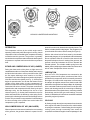
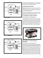
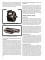
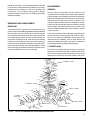
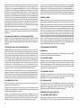
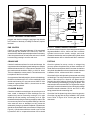
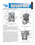
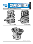
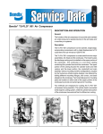
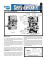
local
search
global
search
operation
troubleshooting
SD-01-335*
main
menu
*Formerly SD-01-5
TU-FLO 700 COMPRESSOR
DISCHARGE
CAP NUT
DISCHARGE
VALVE
DISCHARGE
VALVE SEAT
DISCHARGE
VALVE
SPRING
UNLOADER
MECHANISM
INLET
VALVE
SPRING
INLET
VALVE
PISTON
RINGS
PISTON
CRANKSHAFT
EXTERIOR
CONNECTING
ROD
CRANKCASE
DESCRIPTION
The function of the air compressor is to provide and maintain air under pressure to operate devices in the air brake
and/or auxiliary air systems
The Tu-Flo 700 is a two cylinder, single stage, reciprocating
compressor with a rated displacement of 15.5 cubic feet of
air per minute at 1250 R.P.M. The Tu-Flo 700 is constructed
from three major assemblies, the head, the cylinder block
and the crankcase.
BENDIX TU-FLO 700 COMPRESSOR
(CROSS SECTION)
Two methods are employed for cooling the Tu-Flo 700 during
operation. The cylinder head is connected to the engine’s
cooling system, while the cylinder has external fins for efficient
air cooling.
All Tu-Flo 700 compressors utilize the engine’s pressurized
oil system to lubricate the internal moving parts. A nameplate
is attached to the crankcase to identify the compressor.
The nameplate displays a Bendix piece number or in some
cases an engine or vehicle manufacturer’s piece number,
along with a serial number.
The head houses the discharge valving and is installed on
the upper portion of the cylinder block. The cylinder block
contains the cylinder bores and inlet valves and is mounted
to the crankcase. The crankcase houses the crankshaft
and main bearings.
Various mounting and drive configurations, required by the
numerous vehicle engine designs, are available. Two
governor mounting pads are located on either side of the
cylinder block to provide convenient governor mounting.
TU-FLO 700
BW
NO.
MANUFACTURED BY
SER
NO.
BENDIX
COMPRESSOR NAMEPLATE
1
main
menu
local
search
global
search
operation
troubleshooting
MACK
"FOXHEAD"
CUMMINS
VARIOUS COMPRESSOR MOUNTINGS
MACK
OPERATION
The compressor is driven by the vehicle engine and is
operating continuously while the engine is running. Actual
compression of air is controlled by the compressor unloading
mechanism and the governor. The governor is generally
mounted on the compressor and maintains the brake system
air pressure to a preset maximum and minimum pressure
level.
INTAKE AND COMPRESSION OF AIR (LOADED)
During the down stroke of the piston, a slight vacuum is
created between the ton of the piston and the head, causing
the flat circular inlet valve to move up and off its seat. (Note
the flat square discharge valve remains on its seat.)
Atmospheric air is drawn through the air strainer by the open
inlet valve and into the cylinder (see Fig. 1). As the piston
begins its upward stroke, the air that was drawn into the
cylinder on the down stroke is being compressed. Air
pressure on top of the inlet valve plus the force of its spring,
returns the inlet valve to its seat. The piston continues the
upward stroke and compressed air then flows by the open
discharge valve, into the discharge line and on to the
reservoirs (see Fig. 2). As the piston reaches the top of its
stroke and starts down, the discharge valve spring and air
pressure in the discharge line returns the discharge valve to
its seat. This prevents the compressed air in the discharge
line from returning to the cylinder bore as the intake and
compression cycle is repeated.
NON-COMPRESSION OF AIR (UNLOADED)
When air pressure in the reservoir reaches the cut-out setting
of the governor, the governor allows air to pass from the
2
DETROIT
DIESEL
reservoir into the cavity beneath the unloader pistons. This
lifts the unloader pistons and plungers. The plungers move
up and hold the inlet valves off their seats (see Figure 3).
With the inlet valves held off their seats by the unloader
pistons and plungers, air is pumped back and forth between
the two cylinders. When air is used from the reservoir and
the pressure drops to the cut-in setting of the governor, the
governor closes and exhausts the air from beneath the
unloader pistons. The unloader saddle spring forces the
saddle, pistons and plungers down and the inlet valves return
to their seats. Compression is then resumed.
LUBRICATION
Since all Tu-Flo 700 Compressors are connected to the
engine’s pressurized oil system, a continuous flow of oil is
provided to the compressor, which is eventually returned to
the engine. Oil is fed into the compressor in various ways,
for example: through the rear end cover, the drive end of the
crankshaft or through the front flange adapter. An oil passage
in the crankshaft conducts pressurized oil to the precision
sleeve main bearings and to the connecting rod bearings.
Splash lubrication of the cylinder bores, connecting rod wrist
pin bushings, and the ball type main bearings, on some
models, is obtained as oil is forced out around the crankshaft
journals by engine oil pressure.
COOLING
Air flowing through the engine compartment from the action
of the engine’s fan and the movement of the vehicle assists
in cooling the crankcase. Coolant flowing from the engine’s
cooling system through connecting lines enters the
compressor and flows through the internal passages in the
main
menu
local
search
global
search
operation
troubleshooting
cylinder block and head and back to the engine. Proper
cooling is important in maintaining discharge air temperatures
below the 400°F recommended maximum.
TO RESERVOIR
INLET VALVE
UNLOADER
PLUNGER
DISCHARGE
VALVE
INTAKE
STRAINER
PISTON
TO GOVERNOR
PREVENTIVE MAINTENANCE
Important Note: Review the warranty policy before
performing any intrusive maintenance procedures. An
extended warranty may be voided if intrusive maintenance
is performed during this period.
Every month, 300 operating hours or after each 10,000 miles,
depending on the operating conditions, experience and the
type of strainer used, service the air strainer.
STROKE
POLYURETHANE SPONGE STRAINER
Every 5000 miles or 150 operating hours:
FIGURE 1 - INTAKE
TO RESERVOIR
DISCHARGE
VALVE
INLET VALVE
UNLOADER
PLUNGER
PISTON
Remove and wash all of the parts. The strainer element
should be cleaned or replaced. If the element is cleaned, it
should be washed in a commercial solvent or a detergent
and water solution. The element should be saturated in clean
engine oil, then squeezed dry before replacing it in the
strainer. Be sure to replace the air strainer gasket if the
entire air strainer is removed from the compressor intake.
INTAKE
STRAINER
TO GOVERNOR
STROKE
FIGURE 2 - COMPRESSION
FIGURE 4 - POLYURETHANE SPONGE STRAINER
TO RESERVOIR
DISCHARGE
VALVE
INLET VALVE
UNLOADER
PLUNGER
PISTON
INTAKE
STRAINER
TO GOVERNOR
STROKE
FIGURE 3 - UNLOADING
DRY ELEMENT—PLEATED PAPER AIR
STRAINER
Every 20,000 miles or 800 operating hours:
Remove the spring clips from either side of mounting baffle
and remove the cover. Replace the pleated paper filter and
remount the cleaned cover making sure the filter is in
position. Be sure to replace the air strainer gasket if the
entire air strainer is removed from the compressor intake.
(Note: Some compressors are fitted with compressor intake
adapters which allow the compressor intake to be connected
to the engine air cleaner.) In this case, the compressor
receives a supply of clean air from the engine air cleaner.
When the engine air filter is changed, the compressor intake
adapter should be checked. If it is loose, remove the intake
3
main
menu
local
search
adapter, clean the strainer plate, if applicable, and replace
the intake adapter gasket, and reinstall the adapter securely.
Check line connections both at the compressor intake
adapter and at the engine air cleaner. Inspect the connecting
line for ruptures and replace it if necessary.
global
search
operation
troubleshooting
Every 24 months, 7200 operating hours or after each
200,000 miles:
Perform a thorough inspection as indicated below and
depending upon the results of this inspection or experience,
disassemble the compressor, clean and inspect all parts
thoroughly, repair or replace all worn or damaged parts using
only genuine Bendix replacements or replace the
compressor with a genuine Bendix remanufactured unit.
Important: Should it be necessary to drain the engine cooling
system to prevent damage from freezing, the cylinder head
of the compressor must also be drained.
GENERAL SERVICE CHECKS
INSPECTION
FIGURE 5 - PAPER AIR STRAINER DRY ELEMENTPLEATED
It is of the utmost importance that the compressor receives
a clean supply of air. The air strainer must be properly
installed and kept clean. If the compressor intake is connected
to the engine air cleaner, supercharger, etc., these
connections must be properly installed and maintained.
Check the compressor mountings to be sure they are secure.
Check the drive for proper alignment, belt tension, etc.
Inspect the oil supply and return lines. Be sure these lines
are properly installed and that the compressor is getting the
proper supply of oil, and just as important, that the oil is
returning to the engine. Check the coolant lines to and from
the compressor and see that the cooling fins on the
crankcase are not clogged with dirt, grease, etc. Check the
unloader mechanism for proper and prompt operation.
OPERATING TESTS
FIGURE 6 - COMPRESSOR INTAKE ADAPTER
Every 6 months, 1800 operating hours or after each
50,000 miles:
Remove the discharge head fittings and inspect the
compressor discharge port and discharge line for excessive
carbon deposits. If excessive buildup is noted in either, the
discharge line must be cleaned or replaced and the
compressor checked more thoroughly, paying special
attention to the air induction system, oil supply and return
system, and proper cooling. If necessary, repair or replace
the compressor. Check for proper belt and pulley alignment
and belt tension. Adjust if necessary, paying special attention
not to over tighten the belt tension. Check for noisy
compressor operation, which could indicate a worn drive
gear coupling or a loose pulley. Adjust and/or replace as
necessary. Check all compressor mounting bolts and
retighten evenly if necessary. Check for leakage and proper
unloader mechanism operation. Replace if defective in any
way.
4
Vehicles manufactured after the effective date of FMVSS
121, with the minimum required reservoir volume, must have
a compressor capable of raising air system pressure from
85-100 P.S.I. in 25 seconds or less. This test is performed
with the engine operating at maximum governed speed. The
vehicle manufacturer must certify this performance on new
vehicles with appropriate allowances for air systems with
greater than the minimum required reservoir volume.
AIR LEAKAGE TESTS
Leakage past the discharge valves can be detected by
removing the discharge line, applying shop air back through
the discharge port and listening for escaping air. Also, the
discharge valves and the unloader pistons can be checked
for leakage by building up the air system until the governor
cuts out, then stopping the engine. With the engine stopped,
listen for escaping air at the compressor intake. To pinpoint
leakage if noted, apply a small quantity of oil around the
unloader pistons. If there is no noticeable leakage at the
unloader pistons, the discharge valves may be leaking. If
the compressor does not function as described above, or
main
menu
local
search
global
search
leakage is excessive, it is recommended that it be returned
to the nearest authorized Bendix Distributor for a factory
remanufactured compressor. If this is not possible, the
compressor can be repaired using genuine Bendix
replacement parts, in which case, the following information
should prove helpful.
operation
troubleshooting
DISASSEMBLY
GENERAL
Remove road dirt and grease from the exterior of the
compressor with a cleaning solvent. Before the compressor
is disassembled, the following items should be marked to
show their relationship when the compressor is assembled.
Mark both the front and rear end cover in relation to the
crankcase. Mark the drive end of the crankshaft in relation
to the front end cover and the crankcase. Mark the cylinder
head in relation to the block and the block in relation to the
crankcase. Mark the base plate or base adapter in relation
to the crankcase.
REMOVING AND DISASSEMBLY
REMOVING
These instructions are general and are intended to be a
guide, in some cases additional preparations and precautions
are necessary. Chock the wheels of the vehicle and drain
the air pressure from all the reservoirs in the system. Drain
the engine cooling system and the cylinder head of the
compressor. Disconnect all air, water and oil lines leading
to and from the compressor. Remove the drive gear(s) or
pulley from the compressor crankshaft using a gear puller.
Inspect the pulley or gear and associated parts for visible
wear or damage. Since these parts are precision fitted, they
must be replaced if they are worn or damaged.
A convenient method to indicate the above relationship is to
use a metal scribe to mark the parts with numbers or lines.
Do not use a marking method that can be wiped off or
obliterated during rebuilding, such as chalk. Remove all
compressor attachments such as governors, air strainers
or inlet fittings, discharge fittings and pipe plugs.
CYLINDER HEAD
Remove the six cylinder head cap screws (1) and tap the
head with a soft mallet to break the gasket seal. Remove
the inlet valve springs (2) and spring inserts (35) from the
head and inlet valves (3) from their guides in the block.
9
1
CYLINDER
8
7
6
HEAD
34
35 5
18
19
18
19
15
20
2
20
36
37
CYLINDER
3
4
10
36
BLOCK
37
28
23
21
16
FLANGE
ADAPTER
27
24 26
12
17
22
34
35
33
REAR
30
29
32
COVER
31
REAR
26
CRANKSHAFT
14
13
11
COVER
GASKET
CRANKCASE
25
FIGURE 7 - TU-FLO 700 COMPRESSOR (THRU DRIVE) EXPLODED VIEW
5
main
menu
local
search
Remove inlet valve guides (4) from around the inlet valve
seats (34) on the block taking care not to damage seats.
Scrape off any gasket material (5) from the cylinder head
and block. Unscrew the discharge valve seats (6) from the
head and remove the discharge valves (7) and springs (8).
Inspect the discharge valve seats (2) for nicks, cracks, and
excessive wear and replace if necessary. The discharge valve
cap/nut stops (9) should be inspected for wear and replaced
if excessive peening has occurred. To determine if excessive
peening has occurred, measure the discharge valve travel.
Discharge valve travel must not exceed .046 inches. If
discharge valve travel is excessive, replace the cap nut/stop
assembly, discharge valve and spring.
global
search
operation
troubleshooting
The inlet valve seats can be removed if worn or damaged
and are being replaced. Unloader bore bushings should be
inspected but not removed unless they are damaged. If
bushings are to be replaced, they can be removed by running
a 1/8" pipe threaded rod and pulling the bushing straight up
and out. Do not use "easy out" for removing the bushings.
CRANKCASE
Remove the key (22) or keys from the crankshaft and any
burrs on the crankshaft where the key or keys were removed.
Remove the cap screws securing the base plate or base
adapter. Tap with soft mallet to break the gasket seal (11).
Scrape off any gasket material from crankcase and plate or
adapter.
(Note: Through Drive Compressors may have a crankshaft
key at both ends.) Remove the four cap screws (23) securing
front or drive-end end cover or flange adapter. Remove the
end cover, taking care not to damage the crankshaft oil seal
(27) or front main bearing (26), if any. Remove the O-ring
(24) from around the front end cover. Remove the four cap
screws (30) securing the rear end cover and remove the rear
end cover taking care not to damage the rear main bearing
(29), if any. Remove the O-ring (31) from around the end
cover. If the compressor has ball type main bearings, press
the crankshaft and ball bearings from the crankcase, then
press the ball bearings from the crankshaft.
CONNECTING ROD ASSEMBLIES
CLEANING OF PARTS
Discard the inlet valves (3) and springs (2), the discharge
valves (7), springs (8) and the discharge valve seats (6) if
defective.
CRANKCASE BASE PLATE OR ADAPTER
(Note: Before removing the connecting rods, mark each
connecting rod and its cap. Each connecting rod is matched
to its own cap for proper bearing fit, and these parts must
not be interchanged.) Remove the connecting rod bolts (13)
and bearing caps (14). Push the piston (15) with the
connecting rods (16) attached out the top of the cylinders of
the cylinder block. Replace the bearing caps (14) on their
respective connecting rods. Remove the piston rings from
the pistons. If the pistons are to be removed from the
connecting rods, remove the teflon plugs (36) and press the
wrist pins (37) from the pistons and connecting rods.
If the pistons are removed from the rod, inspect the bronze
wrist pin bushing. Press out and replace the bushing if it is
excessively worn. (See inspection of parts) Discard the piston
rings (18-20) and the connecting rod journal bearings (17).
Discard the wrist pin bushings (21) if they were removed.
GENERAL
All parts should be cleaned in a good commercial grade
solvent and dried prior to inspection.
CYLINDER HEAD
Remove all the carbon deposits from the discharge cavities
and all the rust and scale from the cooling cavities of the
cylinder head body. Scrape all the foreign matter from the
body surfaces and use shop air pressure to blow the dirt
particles from all the cavities.
CYLINDER BLOCK
Clean the carbon and dirt from the inlet and unloader
passages. Use shop air pressure to blow the carbon and
dirt deposits from the unloader passages.
CYLINDER BLOCK
OIL PASSAGES
If the compressor is fitted with an air strainer, inlet elbow or
governor remove the same.
Thoroughly clean all oil passages through the crankshaft,
crankcase, end covers, and base plate or base adapter.
Inspect the passages with a wire to be sure. Blow the
loosened foreign matter out with air pressure.
Remove cap screws (23) securing cylinder block to the
crankcase; separate the crankcase and cylinder block and
scrape off any gasket material.
Remove the unloader spring (34), spring saddle (35), and
spring seat (36) from the inlet cavity of the crankcase, using
long nose pliers. With the use of shop air blow the unloader
plungers (37) and guides (33) out of the cylinder block.
6
INSPECTION OF PARTS
CYLINDER HEAD BODY
Inspect the cylinder head for cracks or damage. Apply shop
air pressure to one of the coolant ports with all others
main
menu
local
search
global
search
operation
troubleshooting
PISTON
RINGS
OIL RING
.002
.004
STANDARD
PISTON
RING
EXPANDER
RING
PISTON
RING
.000
.006
OIL RING
FIGURE 8 - MEASURING CYLINDER BORES
plugged, and check for leakage by applying a soap solution
to the exterior of the body. If leakage is detected, replace
the head.
OIL RING
END GAP
.002"
.010"
END COVERS
FIGURE 9 - CORRECT GROOVE CLEARANCE
Check for cracks and external damage. If the crankshaft
main bearings are installed in the end cover, check for
excessive wear and flat spots and replace them if necessary.
If the compressor has an oil seal in the end cover, it should
be removed by pressing it out of the end cover.
be rebored or honed oversize. Oversized pistons and piston
rings are available in .010 in., .020 in. and .030 in. oversizes.
Cylinder bores must be smooth, straight, and round.
Clearance between the cast iron pistons and cylinder bores
should be between .002 in. minimum and .004 in. maximum.
CRANKCASE
PISTONS
Check all crankcase surfaces for cracks and damage. On
compressors where ball bearing main bearings are used the
difference between the O.D. of the outer race and the I.D. Of
the crankcase hole should be .0000 in. to .0015 in. loose.
This is to maintain the correct press fit. The crankcase must
be replaced if the fit is too loose.
Check the pistons for scores, cracks, or enlarged ring
grooves; replace the pistons if any of these conditions are
found. Measure each piston with a micrometer in relation to
the cylinder bore diameter to be sure the diametral clearance
is between .002 in. minimum and .004 in. maximum.
On compressors fitted with precision, sleeve main bearings,
the difference between the O.D. of the crankshaft journal
and the main bearing I.D. must not exceed .0065 in. If the
clearance is greater than .0065 in., the end cover or main
bearing must be replaced.
CYLINDER BLOCK
Check the unloader bore bushings to be sure they are not
worn, rusted, or damaged. If these bushings are to be
replaced, they can be removed by running a 1/8 in. pipe
thread tap into the bushing, and inserting a 1/8 in. pipe
threaded rod and pulling the bushing straight up and out. Do
not use an easy-out for removing these bushings. If the inlet
valve seats are worn or damaged, so they cannot be
reclaimed by facing, they should be replaced. Cylinder bores
should be checked with inside micrometers or calipers (see
Figure 8). Cylinder bores which are scored or out of round
by more than .001 in. or tapered more than .002 in. should
Check the fit of the wrist pins to the pistons and connecting
rod bushings. The wrist pin should be a light press fit in the
piston. If the wrist pin is a loose fit, the piston and pin
assembly should be replaced. Check the fit of the wrist pin
in the connecting rod bushing by rocking the piston. This
clearance should not exceed .0007 in. Replace the wrist pin
bushings if excessive clearance is found. Wrist pin bushings
should be reamed to between .5314 in. and .5317 in. after
being pressed into the connecting rods.
Check the fit of the piston rings in the piston ring grooves.
Check the ring gap with the rings installed in the cylinder
bores. Refer to Figure 9 for correct gap and groove
clearances.
7
main
menu
local
search
global
search
operation
troubleshooting
CRANKSHAFT
Check the crankshaft threads, keyways, tapered ends and
all machined and ground surfaces for wear, scores, or
damage. Standard crankshaft journals are 1.1250 in.- 1.1242
in. in diameter. If the crankshaft journals are excessively
scored or worn or out of round and cannot be reground, the
crankshaft must be replaced. Connecting rod bearing inserts
are available in .010 in., .020 in. and .030 in. undersizes for
compressors with reground crankshafts. Main bearing
journals must be maintained so the ball bearings are a snug
fit or so that no more than .0065 in. clearance exists between
the precision sleeve main bearing and the main bearing
journals on the crankshaft. In crankshafts fitted with oil seal
rings, the oil seal ring groove or grooves must not be worn.
The ring groove walls must have a good finish and they must
be square. Check to be sure the oil passages are open
through the crankshaft.
CONNECTING ROD BEARINGS
Used bearing inserts must be replaced. Connecting rod caps
are not interchangeable. The locking slots of the connecting
rod and cap should be positioned adjacent to each other.
Clearance between the connecting journal and the
connecting rod bearing must not be less than .0003 in. or
more than .0021 in. after rebuilding.
REPAIRS
DISCHARGE VALVES, VALVE STOPS AND
SEATS
If the discharge valve seats merely show signs of slight wear,
they can be dressed by using a lapping stone, grinding
compound and grinding tool. Install the new discharge valve
springs and valves. Screw in the discharge valve seats.
Discharge valve travel should be between .030 in. to .046 in.
To test for leakage by the discharge valves, apply 100 pounds
of air pressure through the cylinder head discharge port and
apply a soap solution to the discharge valves and seats. A
slight leakage in the form of soap bubbles is permissible. If
excessive leakage is found, leave the air pressure applied
and with the use of a fiber or hardwood dowel and a hammer,
tap the discharge valves off their seats several times. This
will help the valves to seat and should reduce the leakage.
With the air pressure still applied at the discharge port of
the cylinder head, check for leakage around the discharge
valve cap nut on the top of the cylinder head casting. No
leakage is permitted.
INLET VALVES AND SEATS
Inlet valves and springs should be replaced, if the inlet valve
seats show signs of slight nicks or scratches. They can be
redressed with a fine piece of emery cloth or by lapping with
8
2
3
4
8
10
7
6
DISCHARGE VALVE,
VALVE STOP
AND SEAT
FIGURE 10
INLET VALVE
AND SEAT
FIGURE 11
a lapping stone, grinding compound and grinding tool. If the
seats are damaged to the extent that they cannot be
reclaimed, they must be replaced. The dimension from the
top of the cylinder block to the inlet valve seat should not
exceed .113 in. nor be less than .101 in.
ASSEMBLY
General Note: All torques specified in this manual are
assembly torques and can be expected to fall off after
assembly is accomplished. Do not retorque after initial
assembly torques fall.
To convert inch pounds of torque to foot pounds of torque,
divide inch pounds by 12.
inch pounds ÷ 12 = foot pounds
To convert foot pounds of torque to inch pounds of torque,
multiply foot pounds by 12.
foot pounds x 12 = inch pounds
INSTALLING THE CRANKSHAFT
Press new sleeve bearings in the end cover and crankcase.
Ensure that the slot in the bearings line up with the oil
passages in the end cover or crankcase. If you have a model
with no oil passage present in the crankcase, press the
sleeve bearing into the crankcase with the slot located 90
degrees from vertical.
Install the front thrust washer with the tang inserted in the
slot toward the flange. Insert the crankshaft and the rear
thrust washer with the tang toward the rear of the compressor.
Place the oil seal ring on the boss of the rear end cover and
install the end cover making sure not to pinch the seal ring.
Ensure the tang of the thrust washer is inserted in the slot
main
menu
local
search
global
search
of the end cover. Fasten the end cover to the crankcase with
the four cover cap screws. Torque the cap screws to 175225 inch pounds in a cross pattern. Note: For cast iron
flange adapters, torque the four 7/16 in. cap screws to 3845 foot pounds. For die cast aluminum end covers, torque
the four 7/16 in. cap screws to 25-30 foot pounds. All end
covers using 5/16 in. cap screws or stud and nuts are torqued
to 15-18 foot pounds. For through drive compressors with a
cast iron end cover, torque the four 7/16 in. cap screws to
25-30 foot pounds.
PISTONS AND CONNECTING RODS
operation
a small hole is drilled in the cylinder block for this purpose.
Position the saddle (35) between the unloader piston guides
(38), so its forks are centered on the guides. Install the
unloader spring (34), making sure it seats over the spring
seats both in the block and on the saddle. Position and
install the inlet valve guides (38), then drop the inlet valves in
their guides. The inlet valves should be a loose sliding fit in
the guides.
36
38
If new wrist pin bushings are to be used, they should be
pressed into the connecting rods so that the oil hole in the
bushing lines up with the one in the rod. The new bushings
should then be reamed or honed to provide between .0001
in. (.00254 mm) and .0006 in. (.01524 mm) clearance on
the wrist pin. Position the connecting rod in the piston and
press in the wrist pin.
Pistons installed in compressors manufactured prior to
November, 1976, will have the wrist pin secured in the piston
by a lock wire extending through matching holes in wrist pin
and piston boss, anchored in a hole in the side wall of the
piston. If the original pistons are used the wrist pin must be
pressed in so the hole in the wrist pin aligns with that of the
piston and secure same by inserting the new lockwire
through the hole in piston and wrist pin and lock the wire by
snapping the short 90 section into the lockwire hole in the
bottom of the piston.
Compressors built after November, 1976, will have the wrist
pin secured by Teflon buttons in either end of the wrist pin,
allowing the wrist pin to float. The Teflon buttons pc. no.
292392 may be used with either new or old wrist pins. The
later design pistons have two rings above the wrist pin and
one below. Install the piston rings in the correct location
with the ring pipmarks up. Stagger the position of the ring
gaps. Prelubricate the piston, piston rings, wrist pins and
connecting rod.
CYLINDER BLOCK
Allign gasket (12), crankcase and cylinder block and secure
with cap screws (23). Torque to 15-19 foot pounds.
UNLOADER
A new unloader kit should used when rebuilding. (Figure
12). (Piece Number 279615). The unloader pistons in the kit
are prelubricated with a special lubricant piece number
239379 and need no additional lubrication. Install the unloader
pistons (28) in their bores being careful not to cut the orings. Position the unloader plungers (37) in their guides
(38) and slip them in and over the tops of the pistons. Install
the unloader spring seat (36) in the cylinder block inlet cavity;
troubleshooting
34
37
28
35
FIGURE 12- UNLOADER MECHANISM
CYLINDER HEAD
Install the inlet valve springs in the cylinder head by applying
a turning motion to the spring after it is in the head. The
turning motion should dig the spring wire into the spring
seat in the bottom of the spring bore in the head Should this
procedure fail after repeated attempts, use a very small
quantity of grease to hold them in place, just enough to
keep the springs from falling out. Place the cylinder head
gasket on the cylinder block. Carefully align the cylinder
head assembly on the block and install the cap screws,
tightening them evenly to a torque of 15-19 foot pounds.
BASE PLATE OR BASE ADAPTER
Position the base plate or base adapter gasket on the
crankcase and install the base plate or base adapter as
marked before disassembly Tighten the six cap screws
securing the cast iron base adapter evenly to a torque of 3845 foot pounds, and 12-16 foot pounds for base plate or
aluminum cover.
TESTING REBUILT COMPRESSOR
In order to properly test a compressor under operating
conditions, a test rack for correct mounting, cooling,
lubricating, and driving the compressor is necessary. Such
tests are not compulsory if the unit has been carefully rebuilt
by an experienced person. A compressor efficiency or buildup test can be run which is not too difficult. An engine
9
main
menu
local
search
lubricated compressor must be connected to an oil supply
line of at least 15 P.S.I. pressure during the test and an oil
return line must be installed to keep the crankcase drained.
Connect to the compressor discharge port, a reservoir with
a volume of 1500 cubic inches, including the volume of
connecting line. With the compressor operating at 2100
R.P.M., the time required to raise the reservoir(s) pressure
from 85 P.S.I. to 100 P.S.I. should not exceed 7 seconds.
During this test, the compressor should be checked for
gasket leakage and noisy operation, as well as unloader
operation and leakage.
INSPECTION OF REBUILT UNIT
Check to be sure that covers, plugs, or masking tape are
used to protect all ports if compressor is not to be installed
immediately. Fit the end of all crankshafts with keys, nuts,
and cotter pins as required and then protect the ends against
damage by wrapping with masking tape or friction tape. The
open bottom of a vertical engine lubricated compressors
should be protected against the entrance of dirt during
handling or storage, by installing a temporary cover over the
base.
global
search
operation
troubleshooting
IMPORTANT! PLEASE READ:
When working on or around a vehicle, the following
general precautions should be observed:
1. Park the vehicle on a level surface, apply the parking brakes, and always block the wheels.
2. Stop the engine when working around the vehicle.
3. If the vehicle is equipped with air brakes, make
certain to drain the air pressure from all reservoirs
before beginning any work on the vehicle.
4. Following the vehicle manufacturer’s recommended procedures, deactivate the electrical
system in a manner that removes all electrical
power from the vehicle.
5. When working in the engine compartment the engine should be shut off. Where circumstances
require that the engine be in operation, extreme
caution should be used to prevent personal injury
resulting from contact with moving, rotating, leaking, heated, or electrically charged components.
6. Never connect or disconnect a hose or line containing pressure; it may whip. Never remove a
component or plug unless you are certain all system pressure has been depleted.
7. Never exceed recommended pressures and always
wear safety glasses.
8. Do not attempt to install, remove, disassemble or
assemble a component until you have read and
thoroughly understand the recommended procedures. Use only the proper tools and observe all
precautions pertaining to use of those tools.
9. Use only genuine Bendix replacement parts, components, and kits. Replacement hardware, tubing,
hose, fittings, etc. should be of equivalent size,
type, and strength as original equipment and be
designed specifically for such applications and
systems.
10. Components with stripped threads or damaged
parts should be replaced rather than repaired. Repairs requiring machining or welding should not
be attempted unless specifically approved and
stated by the vehicle or component manufacturer.
11. Prior to returning the vehicle to service, make certain all components and systems are restored to
their proper operating condition.
10
main
menu
local
search
global
search
operation
troubleshooting
TABULATED DATA
Number of cylinders ............................ 2
Bore size ............................................ 2.75 in.
Stroke ................................................. 1.81 in.
Piston displacement at 1250 RPM ...... 15.5 cu. ft.
Maximum recommended RPM
(naturally aspirated) ............................. 3000
Minimum coolant flow at maximum
RPM ................................................... 2.5 gal./min.
Recommended minimum
discharge line size .............................. 5/8 in. OD
Copper Tube
Recommended minimum oil
return line size .................................... 5/8 in. OD Tubing
Recommended minimum oil
supply line size ................................... 1/4 in. OD Tubing
Recommended minimum unloader
line size .............................................. 1/4 in. OD Tubing
Recommended minimum coolant
line size .............................................. 1/2 in. OD Tubing
Recommended maximum inlet
air temperature .................................... 250°F
Recommended maximum
discharge air temperature .................... 400°F
Minimum pressure required
to unload ............................................. 60 PSI
11
main
menu
local
search
global
search
operation
troubleshooting
COMPRESSOR TROUBLESHOOTING CHART
SYMPTOMS
1. Compressor passes
excessive oil as
evidenced by
presence of oil at
exhaust ports of
valving or seeping
from air strainer.
CAUSE
A. Restricted air intake.
REMEDY
A. Check engine or compressor air cleaner and
replace if necessary. Check compressor air
inlet for kinks, excessive bends and be certain
inlet lines have the minimum specified inside
diameter. Recommended minimum inlet line
inside diameter is 5/8“. Recommended
maximum air inlet restriction is 25” of water.
B. Restricted oil return (to
engine).
B. Oil return to the engine should not be in any
way restricted. Check for excessive bends,
kinks and restrictions in the oil return line.
Minimum recommended oil return line size is
5/8" O.D. tubing or equivalent l.D. (1/2"
minimum). Return line must constantly
descend from the compressor to the engine
crankcase. Make certain oil drain passages in
the compressor and mating engine surfaces
are unobstructed and aligned. Special care
must be taken when sealants are used with, or
instead of, gaskets.
C. Poorly filtered inlet air.
C. Check for damaged, defective or dirty air filter
on engine or compressor. Check for leaking,
damaged or defective compressor air intake
components (e.g. induction line, fittings,
gaskets, filter bodies, etc.). The compressor
intake should not be connected to any part of
the exhaust gas recirculation (E.G.R.) system
on the engine.
D. Insufficient compressor
cooling (compressor
runs hot).
D. For air-cooled portions of the compressor:
1. Remove accumulated grease, grime or dirt
from the cooling fins. Replace components
found damaged.
2. Check for damaged cooling fins. Replace
components found damaged.
For water-cooled compressor or water-cooled
portions of the compressor:
1. Check for proper coolant line sizes. Minimum
recommended size is 1/2” O.D. tubing.
2. Check the coolant flow through the
compressor. Minimum allowable flow is 2.5
gallons per minute at engine governed speed.
If low coolant flow is detected, inspect the
coolant lines and fittings for accumulated rust
scale, kinks and restrictions.
3. Water temperature should not exceed 200
degrees Fahrenheit.
4. Optimum cooling is achieved when engine
coolant flows into the cylinder block at one end
and out the compressor cylinder head at the
opposite end.
12
main
menu
local
search
global
search
operation
troubleshooting
COMPRESSOR TROUBLESHOOTING CHART (Continued)
SYMPTOMS
1. (Continued)
2. Noisy compressor
operations.
CAUSE
REMEDY
E. Contaminants not being
regularly drained from
system reservoirs.
E. Check reservoir drain valves to insure that they
are functioning properly. It is recommended
that the vehicle should be equipped with
functioning automatic drain valves, or have all
reservoirs drained to zero (0) psi daily, or
optimally to be equipped with a desiccant-type
air dryer prior to the reservoir system.
F. Compressor runs loaded
an excessive amount of
time.
F. Vehicle system leakage should not exceed
industry standards of 1 psi pressure drop per
minute without brakes applied and 3 psi
pressure drop per minute with brakes applied.
If leakage is excessive, check for system leaks
and repair.
G. Excessive engine
crankcase pressure.
G. Test for excessive engine crankcase pressure
& replace or repair ventilation components as
necessary. (An indication of crankcase
pressure is a loose or partially lifted dipstick.)
H. Excessive engine oil
pressure.
H. Check the engine oil pressure with a test gauge
and compare the reading to the engine
specifications. Bendix does not recommend
restricting the compressor oil supply line
because of the possibility of plugging the
restriction with oil contaminants. Minimum oil
supply line size is 1/4" I.D. tubing.
I.
I. Replace or repair the compressor only after
making certain none of the preceding
installation defects exist.
Faulty compressor.
A. Loose drive gear or
pulley.
A. Inspect the fit of the drive gear on pulley on the
compressor crankshaft. The pulley on gear
must be completely seated and the crankshaft
nut must be tight. If the compressor crankshaft
surface or its keyway are damaged, it is an
indication of loose drive components. If
damage to the compressor crankshaft is
detected, replace the compressor. When
installing the drive gear or pulley, torque the
crankshaft nut to the appropriate torque
specifications. Do not back off the crankshaft
nut to align the cotter pin and castellated
nut. (Some compressors do not use castellated
nuts.) Do not use impact wrenches.
13
main
menu
local
search
global
search
operation
troubleshooting
COMPRESSOR TROUBLESHOOTING CHART (Continued)
SYMPTOMS
3. Excessive build-up and
recover time.
Compressor should be
capable of building air
system from 85-100 psi
in 40 seconds with
engine at full governed
rpm. Minimum
compressor
performance is certified
to meet Federal
requirements by the
vehicle manufacturer.
Do not downsize the
original equipment
compressor.
CAUSE
REMEDY
B. Excessively worn drive
couplings or gears.
B. Inspect drive gear and couplings and engine for
excessive wear. Replace as necessary.
(Nonmetallic gears should be replaced when the
compressor is changed.) Drive gear should be
metal-type on Detroit Diesel engine.
C. Compressor cylinder
head or discharge line
restrictions.
C. Inspect the compressor discharge port and
discharge line for carbon build-up. If carbon is
detected, check for proper cooling to the
compressor. (See Cause and Remedy (D) under
Symptom #1.) Inspect the discharge line for
kinks and restrictions. Replace discharge line as
necessary.
D. Worn or burned out
bearings.
D. Check for proper oil pressure in the compressor.
Minimum required oil pressure: 5 psi engine
idling, 15 psi maximum governed engine rpm.
Check for excessive oil temperature—should not
exceed 240 degrees Fahrenheit.
E. Faulty compressor.
E. Replace or repair the compressor after
determining none of the preceding installation
defects exist.
A. Dirty induction air filter.
A. Inspect engine or compressor air filter and
replace if necessary.
B. Restricted induction
line.
B. Inspect the compressor air induction line for
kinks and restrictions and replace as necessary.
C. Restricted discharge
line or compressor
discharge cavity.
C. Inspect the compressor discharge port and line
for restrictions and carbon build-up. If a carbon
build-up is found, check for proper compressor
cooling. Replace faulty sections of the discharge
line.
D. Slipping drive
components.
D. Check for faulty drive gears and couplings and
replace as necessary. Check the condition of
drive belts and replace or tighten, whichever is
appropriate.
E. Excessive air system
leakage.
E. Test for excessive system leakage and repair as
necessary. Use the following as a guide: Build
system pressure to governor cutout and allow
the pressure to stabilize for one minute. Using
the dash gauge, note the system pressure and
the pressure drop after two minutes.
The pressure drop for Pre-1975 vehicles should
not exceed:
1. 4 psi for a single vehicle.
2. 6 psi for a tractor trailer.
3. 10 psi for a tractor and 2 trailers.
14
main
menu
local
search
global
search
operation
troubleshooting
COMPRESSOR TROUBLESHOOTING CHART (Continued)
SYMPTOMS
CAUSE
REMEDY
The pressure drop for Post-1975 vehicles should
not exceed:
3. (Continued)
1. 2 psi in each reservoir for a single vehicle.
2. 6 psi in each reservoir for a tractor and trailer.
3. 8 psi in each reservoir for a tractor and 2
trailers.
4. Compressor fails to
unload.
5. Compressor leaks oil.
F. Sticking unloader
pistons.
F. Check the operation of the unloading pistons in
the inlet cavity of the compressor. Both pistons
should have the plunger flanges resting on the
inlet cavity floor when the compressor is loaded
(pumping air). If the pistons and plunger are not
fully retracted, check for proper operation of the
compressor air governor. If the governor is
operating properly, replace the unloader pistons
and plungers and inspect their bores in the
cylinder block. Clean lubricate as necessary.
Inspect for bent, linked or blocked tubing leading
to or from the governor.
G. Faulty compressor.
G. Replace or repair the compressor after
determining none of the preceding installation
defects exist.
A. Faulty governor or
governor installation.
A. Test the governor for proper operation and
inspect air lines to and from the governor for
kinks or restrictions. Replace or repair the
governor or its connecting air lines.
B. Faulty or worn unloader
pistons or bores.
B. Inspect for worn, dirty or corroded unloader
pistons and their bores. Replace as necessary.
A. Damaged mounting
gasket.
A. Check the compressor mounting bolt torque. If
the mounting bolt torque is low, replace the
compressor mounting gasket before retorquing
the mounting bolts.
B. Cracked crankcase or
end cover.
B. Visually inspect the compressor exterior for
cracked or broken components. Cracked or
broken crankcases or mounting flanges can be
caused by loose mounting bolts. The end cover
can be cracked by overtorquing fitting or plugs
installed in the end cover. Replace or repair the
compressor as necessary.
C. Loose end cover cap
cover.
C. Check the cap screw torques and tighten as
necessary.
D. Loose oil supply or
return line fittings.
D. Check the torque of external oil line fittings and
tighten as necessary.
E. Porous compressor
casting.
E. Replace the compressor if porosity is found.
15
main
menu
local
search
global
search
operation
troubleshooting
COMPRESSOR TROUBLESHOOTING CHART (Continued)
SYMPTOMS
CAUSE
REMEDY
5. (Continued)
F. Mounting flange or end
cover, o-ring or gasket missing, cut or
damaged.
F. Replace as necessary.
6. Compressor constantly
cycles (compressor
remains unloaded for
a very short time).
A. Leaking compressor
unloader pistons.
A. Remove the compressor inlet air strainer or
fitting. With the compressor unloaded (not
compressing air), check for air leakage.
Replace as necessary.
B. Faulty Governor.
B. Test the governor for proper operation and
repair or replace as necessary.
C. Excessive system
leakage.
C. Test for excessive system leakage as
instructed in Symptom #3 Remedy E. Reduce
leakage wherever possible.
D. Excessive reservoir
contaminants.
D. Drain reservoirs.
A. Improperly installed
plugs and coolant line
fittings.
A. Check torque of fittings and plugs and tighten
as necessary. Overtorqued fittings and plugs
can crack the head or block casting.
B. Freeze cracks due to
improper antifreeze
strength.
B. Test antifreeze and strengthen as necessary.
Check coolant flow through compressor to
assure the proper antifreeze mixture reaches
the compressor.
C. Faulty compressor
(porous castings).
C. If casting porosity is detected, replace the
compressor.
A. Restricted discharge
line.
A. Clear restriction or replace line.
B. Loose head bolts.
B. Tighten evenly to a torque of 25-30 foot
pounds.
C. Faulty compressor or
head gasket.
C. Check for rough or poorly machined head or
block surfaces. Replace necessary
components.
7. Compressor leaks
coolant.
8. Compressor head
gasket failure.
16
BW1422 © Honeywell Commercial Vehicle Systems Company. 1/1999 Printed in U.S.A.