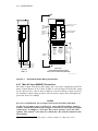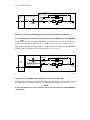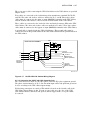
1
HA3000 20-80 kVA
Uninterruptible Power System
Installation Manual
Order Number EK-HA32X-IN-002
Digital Equipment Corporation
November 1991
The information in this document is subject to change without notice and should not be construed as a
commitment by Digital Equipment Corporation. Digital Equipment Corporation assumes no responsibility for
any errors that may appear in this document.
Possession, use, duplication, or dissemination of the software described in this documentation is authorized
only pursuant to a valid written license from Digital or the third-party owner of the software copyright.
No responsibility is assumed for the use or reliability of software on equipment that is not supplied by
Digital Equipment Corporation.
Copyright © Digital Equipment Corporation 1991
All Rights Reserved.
Printed in U.S.A.
The postpaid Reader’s Comment Card included in this document requests the user’s critical evaluation to
assist in preparing future documentation.
FCC NOTICE: The equipment described in this manual generates, uses, and may emit radio frequency
energy. The equipment has been type tested and found to comply with the limits for a Class A computing
device pursuant to Subpart J of Part 15 of FCC Rules, which are designed to provide reasonable protection
against such radio frequency interference when operated in a commercial environment. Operation of this
equipment in a residential area may cause interference, in which case the user at his own expense may be
required to take measures to correct the interference.
The Digital logo is a trademark of Digital Equipment Corporation.
This document was prepared and published by Educational Services Development and Publishing, Digital
Equipment Corporation.
Contents
ix
About This Manual
1
INSTALLATION REFERENCE CHECKLISTS
1.1
CUSTOMER RESPONSIBILITIES . . . . . . . . . . . . . . . . . . . . . . . . . . . .
1.1.1
Site Preparation . . . . . . . . . . . . . . . . . . . . . . . . . . . . . . . . . . . . . . . .
1.1.2
Delivery/Handling . . . . . . . . . . . . . . . . . . . . . . . . . . . . . . . . . . . . . . .
1–1
1–1
1–2
1.2
1–3
TRUCKER/MOVER/RIGGER RESPONSIBILITIES . . . . . . . . . . . . . . .
1.3
ELECTRICIAN RESPONSIBILITIES .
1.3.1
HA32A UPS Cabinet . . . . . . . . . . . .
1.3.2
HA32B UPS Battery Cabinet . . . . .
1.3.3
HA32C/D/E UPS Auxiliary Cabinet
1.3.4
HA33D/F UPS CSA Cabinet . . . . . .
1.3.5
HA32J/K UPS Distribution Cabinet
1.3.6
HA320-A3 Remote Alarm Panel . . .
2
.
.
.
.
.
.
.
.
.
.
.
.
.
.
.
.
.
.
.
.
.
.
.
.
.
.
.
.
.
.
.
.
.
.
.
.
.
.
.
.
.
.
.
.
.
.
.
.
.
.
.
.
.
.
.
.
.
.
.
.
.
.
.
.
.
.
.
.
.
.
.
.
.
.
.
.
.
.
.
.
.
.
.
.
.
.
.
.
.
.
.
.
.
.
.
.
.
.
.
.
.
.
.
.
.
.
.
.
.
.
.
.
.
.
.
.
.
.
.
.
.
.
.
.
.
.
.
.
.
.
.
.
.
.
.
.
.
.
.
.
.
.
.
.
.
.
.
.
.
.
.
.
.
.
.
.
.
.
.
.
.
.
.
.
.
.
.
.
.
.
.
.
.
.
.
1–3
1–3
1–4
1–5
1–6
1–7
1–8
1.4
DIGITAL SERVICES RESPONSIBILITIES
1.4.1
Site Preparation . . . . . . . . . . . . . . . . . . .
1.4.2
Delivery/Handling . . . . . . . . . . . . . . . . . .
1.4.3
Initial Startup . . . . . . . . . . . . . . . . . . . . .
.
.
.
.
.
.
.
.
.
.
.
.
.
.
.
.
.
.
.
.
.
.
.
.
.
.
.
.
.
.
.
.
.
.
.
.
.
.
.
.
.
.
.
.
.
.
.
.
.
.
.
.
.
.
.
.
.
.
.
.
.
.
.
.
.
.
.
.
.
.
.
.
.
.
.
.
.
.
.
.
. 1–9
. 1–9
. 1–10
. 1–10
SITE PREPARATION
2.1
GENERAL . . . . . . . . . . . . . . . . . . . . . . . . . . . . . . . . . . . . . . . . . . . . . .
2–1
2.2
STORAGE . . . . . . . . . . . . . . . . . . . . . . . . . . . . . . . . . . . . . . . . . . . . . . .
2–1
2.3
HA32A UPS CABINET . . . . . . . . . . . . . . . . . . . . . . . . . . . . . . . . . . . . .
2–2
2.4
HA32B UPS BATTERY CABINET . . . . . . . . . . . . . . . . . . . . . . . . . . . .
2.4.1
Environmental Considerations . . . . . . . . . . . . . . . . . . . . . . . . . . . . .
2.4.2
Mechanical Considerations . . . . . . . . . . . . . . . . . . . . . . . . . . . . . . . .
2–6
2–6
2–6
2.5
HA32C/D/E UPS AUXILIARY CABINET . . . . . . . . . . . . . . . . . . . . . . .
2–8
2.6
HA33D/F UPS CSA CABINET . . . . . . . . . . . . . . . . . . . . . . . . . . . . . . . 2–10
2.7
HA32J/K UPS DISTRIBUTION CABINET . . . . . . . . . . . . . . . . . . . . . . 2–12
iii
iv Contents
3
HA3000 UPS RECEIVING AND HANDLING
3.1
GENERAL . . . . . . . . . . . . . . . . . . . . . . . . . . . . . . . . . . . . . . . . . . . . . .
3–1
3.2
RECEIVING . . . . . . . . . . . . . . . . . . . . . . . . . . . . . . . . . . . . . . . . . . . . .
3–1
3.3
HANDLING . . . . . . . . . . . . . . . .
3.3.1
Removing Unit from Truck . . .
3.3.2
Removing Shipping Carton . . .
3.3.3
Removing Unit from Pallet . . .
3.3.4
Recommended Layout . . . . . . .
3.3.5
Moving Unit to Final Position .
3.3.6
Caster Removal . . . . . . . . . . . .
4
.
.
.
.
.
.
.
.
.
.
.
.
.
.
.
.
.
.
.
.
.
.
.
.
.
.
.
.
.
.
.
.
.
.
.
.
.
.
.
.
.
.
.
.
.
.
.
.
.
.
.
.
.
.
.
.
.
.
.
.
.
.
.
.
.
.
.
.
.
.
.
.
.
.
.
.
.
.
.
.
.
.
.
.
.
.
.
.
.
.
.
.
.
.
.
.
.
.
.
.
.
.
.
.
.
.
.
.
.
.
.
.
.
.
.
.
.
.
.
.
.
.
.
.
.
.
.
.
.
.
.
.
.
.
.
.
.
.
.
.
.
.
.
.
.
.
.
.
.
.
.
.
.
.
.
.
.
.
.
.
.
.
.
.
.
.
.
.
.
.
.
.
.
.
.
.
.
.
.
.
.
.
.
.
.
.
.
.
.
.
.
.
.
.
.
.
.
.
.
.
.
.
.
3–2
3–3
3–3
3–3
3–4
3–5
3–5
GENERAL . . . . . . . . . . . . . . . . . . . . . . . . . . . . . . . . . . . . . . . . . . . . . .
4–1
4.2
HA32A UPS Cabinet . . . . . . . . . . . . . . . . . . . . . . . . . . . . . . . . . . . . . . .
4.2.1
Main AC Input (MAINS1) Connection . . . . . . . . . . . . . . . . . . . . . . .
4.2.2
Bypass AC Input (MAINS2) Connection . . . . . . . . . . . . . . . . . . . . . .
4.2.3
UPS Output Load Connection . . . . . . . . . . . . . . . . . . . . . . . . . . . . . .
4.2.4
Battery Connection . . . . . . . . . . . . . . . . . . . . . . . . . . . . . . . . . . . . . .
4.2.5
UPS Battery Cabinet Control Wire Connections (TB1) . . . . . . . . . . .
4.2.5.1
Battery Cabinet Circuit Breaker (QF1) Control Wiring . . . . . . . . .
4.2.5.2
DC Ground Fault Detector Control Wiring . . . . . . . . . . . . . . . . . .
4.2.5.3
Smoke Detector Control Wiring . . . . . . . . . . . . . . . . . . . . . . . . . .
4.2.6
Contact Closure Control Wire Connections (TB2) . . . . . . . . . . . . . . .
4.2.7
Remote Status Panel and Remote Alarm Panel Control Wire
Connections (TB3) . . . . . . . . . . . . . . . . . . . . . . . . . . . . . . . . . . . . . .
4.2.7.1
Remote Status Panel Control and Power Wire Connections . . . . .
4.2.7.2
Remote Alarm Panel Control and Power Wire Connections . . . . .
4.2.8
Checks After Installation . . . . . . . . . . . . . . . . . . . . . . . . . . . . . . . . .
4–1
4–2
4–4
4–4
4–4
4–5
4–6
4–6
4–6
4–7
INSTALLATION
4.1
4.3
HA32B UPS BATTERY CABINET . . . . . . . . . . . . . . . . .
4.3.1
General Installation . . . . . . . . . . . . . . . . . . . . . . . . . .
4.3.2
Single UPS Battery Cabinet/HA32A UPS Installation
4.3.3
Two UPS Battery Cabinets/HA32A UPS Installation .
4.3.4
Power Cable Connections . . . . . . . . . . . . . . . . . . . . . .
4.3.5
Control Wire Connections . . . . . . . . . . . . . . . . . . . . . .
4.3.6
Interbattery Link Connection . . . . . . . . . . . . . . . . . . .
4.3.7
Checks After Installation . . . . . . . . . . . . . . . . . . . . . .
4.3.8
Reassembling the UPS Battery Cabinet . . . . . . . . . . .
.
.
.
.
.
.
.
.
.
.
.
.
.
.
.
.
.
.
.
.
.
.
.
.
.
.
.
.
.
.
.
.
.
.
.
.
.
.
.
.
.
.
.
.
.
.
.
.
.
.
.
.
.
.
.
.
.
.
.
.
.
.
.
.
.
.
.
.
.
.
.
.
.
.
.
.
.
.
.
.
.
.
.
.
.
.
.
.
.
.
4–7
4–7
4–8
4–8
.
.
.
.
.
.
.
.
.
4–9
4–9
4–10
4–11
4–11
4–12
4–12
4–12
4–13
4.4
HA32C/D/E UPS AUXILIARY CABINET . . . . . . . . . . . . . . . . . . . . . . .
4.4.1
Power Cable Connections . . . . . . . . . . . . . . . . . . . . . . . . . . . . . . . . .
4.4.1.1
AC Input Connection for Input Isolation Transformer Option . . . .
4.4.1.2
Connecting the Isolation Transformer for Both the UPS Main AC
Input (MAINS1) and Bypass AC Input (MAINS2) . . . . . . . . . . . .
4.4.1.3
Connecting the Isolation Transformer for the UPS Bypass AC
Input (MAINS2) Only . . . . . . . . . . . . . . . . . . . . . . . . . . . . . . . . .
4–14
4–16
4–16
4–19
4–20
Contents v
4.4.1.4
4.4.1.5
4.4.2
4.4.3
A
B
Connecting the Isolation Transformer for the UPS Main AC Input
(MAINS1) Only . . . . . . . . . . . . . . . . . . . . . . . . . . . . . . . . . . . . . .
Connecting the Input Harmonic Current Filter . . . . . . . . . . . . . .
Control/Interface Wiring . . . . . . . . . . . . . . . . . . . . . . . . . . . . . . . . . .
Checks After Installation . . . . . . . . . . . . . . . . . . . . . . . . . . . . . . . . .
4–21
4–21
4–23
4–23
4.5
HA33D/F UPS CSA CABINET . . . . . . . . . . . . . . . . . . . . . . . . . . . . . . .
4.5.1
Power Cable Connections . . . . . . . . . . . . . . . . . . . . . . . . . . . . . . . . .
4.5.1.1
Connecting the HA33D with Input Isolation/Step-Down
Transformer and CSA Assembly . . . . . . . . . . . . . . . . . . . . . . . . .
4.5.1.2
Connecting the HA33F with CSA Assembly Only . . . . . . . . . . . . .
4.5.2
Control/Interface Wiring . . . . . . . . . . . . . . . . . . . . . . . . . . . . . . . . . .
4.5.3
Checks After Installation . . . . . . . . . . . . . . . . . . . . . . . . . . . . . . . . .
4–26
4–27
4–29
4–29
4.6
HA32J/K UPS DISTRIBUTION CABINET . . . . . . . . . . . . . . . . . . . . .
4.6.1
Power Cable Connections . . . . . . . . . . . . . . . . . . . . . . . . . . . . . . . .
4.6.1.1
AC Input Connection Without Isolation/Step-Down Transformer
4.6.1.2
AC Input Connection With Isolation/Step-Down Transformer . . .
4.6.2
Control/Interface Wiring . . . . . . . . . . . . . . . . . . . . . . . . . . . . . . . . .
4.6.3
Installation and Connection of Optional Digital Output Cables . . .
4.6.3.1
Output Circuit Breaker Installation . . . . . . . . . . . . . . . . . . . . . .
4.6.3.2
Output Cable Installation . . . . . . . . . . . . . . . . . . . . . . . . . . . . . .
4.6.4
Non-Digital Output Cables . . . . . . . . . . . . . . . . . . . . . . . . . . . . . . .
4.6.5
Checks After Installation . . . . . . . . . . . . . . . . . . . . . . . . . . . . . . . .
4–30
4–31
4–31
4–31
4–32
4–32
4–32
4–35
4–35
4–36
.
.
.
.
.
.
.
.
.
.
4–24
4–26
4.7
HA320-AA/AB REMOTE STATUS PANEL . . . . . . . . . . . . . . . . . . . . . . 4–37
4.8
HA320-A3 REMOTE ALARM PANEL . . . . . . . . . . . . . . . . . . . . . . . . . . 4–38
4.9
HA320-C2 DC GROUND FAULT DETECTOR . . . . . . . . . . . . . . . . . . . 4–39
4.10
HA320-B1 SMOKE DETECTOR . . . . . . . . . . . . . . . . . . . . . . . . . . . . . . 4–40
ELECTRICAL CONSIDERATIONS
A.1
GENERAL . . . . . . . . . . . . . . . . . . . . . . . . . . . . . . . . . . . . . . . . . . . . . .
A–1
A.2
TERMS AND DEFINITIONS . . . . . . . . . . . . . . . . . . . . . . . . . . . . . . . .
A–1
SPECIFICATIONS
Index
Figures
2–1
2–2
2–3
2–4
2–5
2–6
2–7
Right-Side Cable Access for the UPS Cabinet . . . . . . . .
Bottom View, 20 and 40 kVA Models . . . . . . . . . . . . . . .
Bottom View, 60 and 80 kVA Models . . . . . . . . . . . . . . .
Floor Tile Cutout . . . . . . . . . . . . . . . . . . . . . . . . . . . . . .
UPS Auxiliary Cabinet Placement . . . . . . . . . . . . . . . .
UPS CSA Cabinet Placement . . . . . . . . . . . . . . . . . . . .
UPS Cabinet and UPS Distribution Cabinet Placement
.
.
.
.
.
.
.
.
.
.
.
.
.
.
.
.
.
.
.
.
.
.
.
.
.
.
.
.
.
.
.
.
.
.
.
.
.
.
.
.
.
.
.
.
.
.
.
.
.
.
.
.
.
.
.
.
.
.
.
.
.
.
.
.
.
.
.
.
.
.
.
.
.
.
.
.
.
. 2–2
. 2–3
. 2–4
. 2–6
. 2–8
. 2–10
. 2–12
vi Contents
2–8
3–1
3–2
4–1
4–2
4–3
4–4
4–5
4–6
4–7
4–8
4–9
4–10
4–11
4–12
4–13
4–14
4–15
4–16
4–17
4–18
4–19
4–20
4–21
UPS Cabinet, UPS Auxiliary Cabinet or UPS CSA Cabinet, and UPS
Distribution Cabinet Placement . . . . . . . . . . . . . . . . . . . . . . . . . . . . . .
Handling the HA3000 Series Cabinets . . . . . . . . . . . . . . . . . . . . . . . . .
HA3000 Series UPS Layout . . . . . . . . . . . . . . . . . . . . . . . . . . . . . . . . .
UPS Cabinet Power Wiring Connections . . . . . . . . . . . . . . . . . . . . . . . .
Yellow Jumper Tag . . . . . . . . . . . . . . . . . . . . . . . . . . . . . . . . . . . . . . . .
UPS Cabinet Control Wiring Connections . . . . . . . . . . . . . . . . . . . . . . .
UPS Battery Cabinet Power and Control Wiring Connections . . . . . . .
UPS Auxiliary Cabinet Mounting Holes . . . . . . . . . . . . . . . . . . . . . . . .
Right Side Cable Entry Area . . . . . . . . . . . . . . . . . . . . . . . . . . . . . . . .
UPS Auxiliary Cabinet Cable Trays . . . . . . . . . . . . . . . . . . . . . . . . . . .
Connecting the Isolation Transformer . . . . . . . . . . . . . . . . . . . . . . . . . .
UPS Input and Bypass Input Isolation Transformer Configuration . . .
UPS Bypass Input Isolation Transformer Configuration . . . . . . . . . . . .
Alternate UPS Bypass Input Isolation Transformer Configuration . . . .
UPS Input Isolation Transformer Configuration . . . . . . . . . . . . . . . . . .
UPS Cabinet Without Input Harmonic Current Filter Installed . . . . . .
UPS Cabinet with Input Harmonic Current Filter Installed . . . . . . . . .
UPS CSA Cabinet Mounting Holes . . . . . . . . . . . . . . . . . . . . . . . . . . . .
Right Side Cable Entry Area . . . . . . . . . . . . . . . . . . . . . . . . . . . . . . . .
HA33D UPS CSA Cabinet Wiring Diagram . . . . . . . . . . . . . . . . . . . . .
HA33F UPS CSA Cabinet Wiring Diagram . . . . . . . . . . . . . . . . . . . . . .
UPS Distribution Cabinet Mounting Holes . . . . . . . . . . . . . . . . . . . . . .
Square-D Distribution Panelboard . . . . . . . . . . . . . . . . . . . . . . . . . . . .
Bryant Distribution Panelboard . . . . . . . . . . . . . . . . . . . . . . . . . . . . . .
2–13
3–2
3–4
4–2
4–4
4–5
4–11
4–14
4–15
4–16
4–19
4–20
4–20
4–21
4–21
4–22
4–23
4–24
4–25
4–27
4–28
4–30
4–33
4–34
Standard HA32A UPS Models . . . . . . . . . . . . . . . . . . . . . . .
UPS Battery Cabinet Model Numbers . . . . . . . . . . . . . . . . .
UPS Auxiliary Cabinet Weights and Dimensions . . . . . . . . .
UPS CSA Cabinet Weights and Dimensions . . . . . . . . . . . . .
UPS Distribution Cabinet Specifications . . . . . . . . . . . . . . . .
HA32A Currents . . . . . . . . . . . . . . . . . . . . . . . . . . . . . . . . . .
Maximum DC Current Requirements . . . . . . . . . . . . . . . . . .
Interbattery Link Torque Values . . . . . . . . . . . . . . . . . . . . . .
HA32C/D/E UPS Auxiliary Cabinet Electrical Specifications
HA33D/F UPS CSA Cabinet Electrical Specifications . . . . . .
Standard HA32A UPS Models . . . . . . . . . . . . . . . . . . . . . . .
HA32A Currents . . . . . . . . . . . . . . . . . . . . . . . . . . . . . . . . . .
UPS Battery Cabinet Model Numbers . . . . . . . . . . . . . . . . .
Maximum DC Current Requirements . . . . . . . . . . . . . . . . . .
Interbattery Link Torque Values . . . . . . . . . . . . . . . . . . . . . .
UPS Auxiliary Cabinet Weights and Dimensions . . . . . . . . .
HA32C/D/E UPS Auxiliary Cabinet Electrical Specifications
UPS CSA Cabinet Weights and Dimensions . . . . . . . . . . . . .
HA33D/F UPS CSA Cabinet Electrical Specifications . . . . . .
2–5
2–7
2–9
2–11
2–14
4–3
4–9
4–12
4–17
4–26
B–4
B–5
B–6
B–6
B–7
B–7
B–8
B–10
B–10
Tables
2–1
2–2
2–3
2–4
2–5
4–1
4–2
4–3
4–4
4–9
B–1
B–2
B–3
B–4
B–5
B–6
B–7
B–8
B–9
.
.
.
.
.
.
.
.
.
.
.
.
.
.
.
.
.
.
.
.
.
.
.
.
.
.
.
.
.
.
.
.
.
.
.
.
.
.
.
.
.
.
.
.
.
.
.
.
.
.
.
.
.
.
.
.
.
.
.
.
.
.
.
.
.
.
.
.
.
.
.
.
.
.
.
.
.
.
.
.
.
.
.
.
.
.
.
.
.
.
.
.
.
.
.
.
.
.
.
.
.
.
.
.
.
.
.
.
.
.
.
.
.
.
.
.
.
.
.
.
.
.
.
.
.
.
.
.
.
.
.
.
.
.
.
.
.
.
.
.
.
.
.
.
.
.
.
.
.
.
.
.
Contents vii
B–10 UPS Distribution Cabinet Specifications . . . . . . . . . . . . . . . . . . . . . . . . B–11
About This Manual
OVERVIEW
This manual is intended for use by the customer for site preparation, by the customer’s
electrician to install the HA3000 20-80 kVA series Uninterruptible Power System (UPS),
and by the Digital Services Engineer to ensure proper installation before performing
the startup procedures. It provides site preparation information and instructions for
receiving, handling, storing, and installing the UPS for the customer and the customer’s
electrician. The installation must be completed before calling Digital Services to
perform the startup procedures. Incomplete installation will result in startup
delays.
WARNING
The HA32B UPS Battery Cabinet contains batteries that are wired together to
produce a high voltage. Even with no external connections, hazardous voltage
exists inside the UPS Battery Cabinet that can cause severe burns or death
upon contact.
The manual covers the following topics:
•
Chapter 1 contains a checklist of the responsibilities of the customer, customer’s
electrician, trucker/mover/rigger, and Digital Services during site preparation,
delivery/handling, installation, and startup of the HA3000 series UPS.
•
Chapter 2 contains site preparation information for the HA32A UPS cabinet, the
HA32B UPS Battery Cabinet, the HA32C/D/E UPS Auxiliary Cabinet, the HA33D/F
UPS CSA Cabinet, and the HA32J/K UPS Distribution Cabinet.
•
Chapter 3 contains information for receiving and handling the HA3000 series
equipment cabinets.
•
Chapter 4 contains the installation procedures for the HA32A UPS cabinet, the
HA32B UPS Battery Cabinet, the HA32C/D/E UPS Auxiliary Cabinet, the HA33D/F
UPS CSA Cabinet, the HA32J/K UPS Distribution Cabinet, the HA320-AA/AB
Remote Status Panel, the HA320-A3 Remote Alarm Panel, the HA320-B1 Smoke
Detector, and the HA320-C2 DC Ground Fault Detector.
•
Appendix A contains electrical considerations for the HA32A UPS cabinet.
•
Appendix B contains specification tables for the HA3000 series components.
ix
x About This Manual
RELATED DOCUMENTS
Title
Part Number
HA3000 20-80 kVA Uninterruptible Power System User Guide
EK-HA32X-UG
HA3000 20-80 kVA Uninterruptible Power System Installation Drawings
EK-HA32X-ID
HA3000 Uninterruptible Power System Handling Instructions
EK-HA32X-HI
HA3000 Uninterruptible Power System Technical Manual
EK-HA32X-TM
1
INSTALLATION REFERENCE CHECKLISTS
1.1 CUSTOMER RESPONSIBILITIES
The following sections contain checklists of the responsibilities of the customer during
site preparation and delivery/handling of the HA3000 series UPS.
1.1.1 Site Preparation
The customer’s responsibilities during site preparation are listed below.
Check Off
Function
Task
Electrical
Connections
Obtain an electrician to perform the electrical
connections that are described in Chapter 4.
Site Selection
Select the area where the HA3000 series UPS will be
installed. Where it is located will have a bearing on
the electrical installation cost and installation time.
NOTE: It is highly recommended that the HA3000
series UPS be installed in a computer room
environment with a raised floor.
Physical Size and
Weight
Obtain the size and weight information on the HA3000
series cabinets that are to be installed. Refer to the
HA3000 20-80 kVA Uninterruptible Power System
Installation Drawings (EK-HA32X-ID) or to Chapter 2
in this manual.
Physical Placement
Determine the exact physical placement of the
cabinets. The cabinet dimensions and service
clearances must be taken into consideration. The
following is a list of the minimum service clearances
required.
Rear - 60.96 cm (24 in)
Front - 121.92 cm (48 in)
Side - 60.96 cm (24 in) on each end of the cabinet
configuration
Top - 91.44 cm (36 in)
NOTE: Local codes may require more clearance.
Floor Loading
Ensure that the floor can support the total
configuration weight. If there is any question in this
regard, a structural engineer should be consulted.
1–1
1–2 INSTALLATION REFERENCE CHECKLISTS
Check Off
Function
Task
Configuration Layout
Plan the configuration layout using the following
placement order (left to right): UPS Battery Cabinet(s),
UPS cabinet, UPS Auxiliary Cabinet, UPS CSA
Cabinet, and UPS Distribution Cabinet.
Floor Marking
Mark the outside dimensions of the cabinet
configuration and the floor cutouts on the floor with
tape so that placement and any floor cutouts will be in
the correct place.
Floor Cutouts
On a raised floor, ensure that floor tile cutouts are
provided for cool air supply and cabling. Refer to the
HA3000 20-80 kVA Uninterruptible Power System
Installation Drawings (EK-HA32X-ID) for the cable
entry areas on the UPS cabinet, the UPS Battery
Cabinet, and the UPS Distribution Cabinet.
CAUTION: If perforated tiles are used for cooling,
ensure that air restricting baffles are not installed
beneath them.
Inside Delivery
Route
Ensure that there is an unobstructed inside delivery
path to the final installation position. Ensure that
elevators, ramps, and flooring along this path can
handle the equipment weights and dimensions.
1.1.2 Delivery/Handling
The customer’s responsibilities during delivery/handling are listed below.
Check Off
Function
Task
Site Delivery
Coordination
Assist Digital Services in assuring proper delivery and
placement of the HA3000 series cabinets.
Configuration
Assembly
Assist Digital Services in removing the appropriate
side skins and cover plates before the cabinets are in
their final position.
Final Assembly
Assist Digital Services in replacing all exterior skins.
Check to ensure that all cabinets are complete.
INSTALLATION REFERENCE CHECKLISTS 1–3
1.2 TRUCKER/MOVER/RIGGER RESPONSIBILITIES
The trucker/mover/rigger’s responsibilities during delivery/handling are listed below.
Check Off
Function
Task
Inside Delivery and
Handling
Deliver the HA3000 series cabinets from the padded
van to the final resting place at the customer’s site.
Follow the handling instructions in Chapter 3.
Caster Assembly
Removal
Remove the yellow caster assemblies beneath each
cabinet after the cabinets have been moved to their
final resting place.
1.3 ELECTRICIAN RESPONSIBILITIES
The following sections contain the responsibilities of the electrician during the
installation of the HA3000 series UPS. The electrician should refer to the HA3000
20-80 kVA Uninterruptible Power System Installation Drawings (EK-HA32X-ID) and to
the procedures in Chapter 4 when performing the actual installation. All electrical site
wiring must comply with the National Electrical Code (ANSI/NFPA 70) and with local
codes as applicable.
1.3.1 HA32A UPS Cabinet
The electrician’s responsibilities during the installation of the HA32A-xx UPS cabinet are
listed below.
Check Off
1 If
Function
Task
Cable Entry/Exit
Perform the cable knockouts and provide the fittings
and conduits for this cabinet. Bottom or right-side
cable entry is possible. Refer to Figure 2–1, Figure 2–2,
and Figure 2–3.
Input Conductor
Sizing
Determine the input conductor sizing for the UPS. The
circuit rating needs to be matched to the input circuit
breaker for the unit being installed. Refer to Table 2–1
for the input circuit breaker ratings for the different
UPS models.
MAINS1 Input
Conductors (supplied
by the electrician)
Provide four wires for the MAINS1 input; three phase
conductors and a ground. If only one power source
is to be used for the MAINS1 and MAINS2 inputs,
the MAINS1 and MAINS2 busbars must be jumpered
together using the correct gauge wire.
MAINS2 Input
Conductors (supplied
by the electrician)
Provide five wires for the MAINS2 input; three phase
conductors, a neutral1 (all four of equal ampacity), and
a ground. If only one power source is to be used for
the MAINS1 and MAINS2 inputs, the MAINS1 and
MAINS2 busbars must be jumpered together using the
correct gauge wire. If no neutral1 is available from
the building distribution system (for example, DELTA
only service entrance), a UPS Auxiliary Cabinet with
an input isolation transformer may be used to derive a
neutral for the UPS cabinet.
an HA32A-Cx cabinet is being installed, a neutral conductor is not required.
1–4 INSTALLATION REFERENCE CHECKLISTS
1.3.2 HA32B UPS Battery Cabinet
The electrician’s responsibilities during the installation of the HA32B-xx UPS Battery
Cabinet are listed below.
Check Off
Function
Task
Cable Entry/Exit
Perform the cable knockouts and provide the fittings
and conduits for this cabinet. Refer to the HA3000
20-80 kVA Uninterruptible Power System Installation
Drawings (EK-HA32X-ID) for cable entry/exit location.
Power and Ground
Connections
(supplied by the
electrician)
Provide three power cables and crimp terminals;
positive, negative, and ground. The battery wiring
should be sized to keep the total cable voltage drop to
less than 0.5 Vdc at the current shown in Table 4–2.
Cable Connections
Connect the cables from the dc output busbars in the
UPS Battery Cabinet (Figure 4–4) to the dc input
busbars in the UPS cabinet (Figure 4–1). Correct
dc polarity must be observed when making these
connections.
Control Wire
Connections
(supplied by the
electrician)
Provide two control wires (600 V rated) for the QF1
24 Vdc UV Release, and connect them from TB1-1
and TB1-2 in the UPS Battery Cabinet (Figure 4–4) to
TB1-1 and TB1-2 in the UPS cabinet (Figure 4–3).
Control Wire
Connections
(supplied by the
electrician)
Provide two control wires (600 V rated) for the QF1
Auxiliary Contacts, and connect them from TB1-4 and
TB1-5 in the UPS Battery Cabinet (Figure 4–4) to
TB1-4 and TB1-5 in the UPS cabinet (Figure 4–3).
Option Dependent
Control Wire
Connections
(supplied by the
electrician)
Provide two control wires (600 V rated) if the DC
Ground Fault Detector is installed in the UPS Battery
Cabinet, and connect them from TB1-7 and TB1-8 in
the UPS Battery Cabinet (Figure 4–4) to TB1-7 and
TB1-8 in the UPS cabinet (Figure 4–3).
Option Dependent
Control Wire
Connections
(supplied by the
electrician)
Provide four control wires (600 V rated) if the Smoke
Detector is installed in the UPS Battery Cabinet,
and connect them from TB1-9, TB1-10, TB1-11, and
TB1-12 in the UPS Battery Cabinet (Figure 4–4) to
TB1-9, TB1-10, TB1-11, and TB1-12 in the UPS cabinet
(Figure 4–3).
INSTALLATION REFERENCE CHECKLISTS 1–5
1.3.3 HA32C/D/E UPS Auxiliary Cabinet
The electrician’s responsibilities during the installation of the HA32C/D/E UPS Auxiliary
Cabinet are listed below.
Check Off
Function
Task
Cable Entry/Exit
Perform the cable knockouts and provide the fittings
and conduits for this cabinet. Right-side cable entry is
possible (Figure 4–6). Refer to the HA3000 20-80 kVA
Uninterruptible Power System Installation Drawings
(EK-HA32X-ID).
Input Conductors
(supplied by the
electrician)
Provide four power cables; three phase conductors
and a ground conductor (all of equal ampacity) if the
UPS Auxiliary Cabinet contains an input isolation
transformer. Refer to Table 4–4 for current ratings.
Refer to the UPS Auxiliary Cabinet installation
instructions in Chapter 4 when making the ac input
cable connections.
If no neutral1 is available from the building
distribution system (for example, DELTA only service
entrance), a UPS Auxiliary Cabinet with an input
isolation transformer may be used to derive a neutral
for the UPS cabinet.
1 If
Output Conductors
Connect the four output cables that are factory
installed in the UPS Auxiliary Cabinet, if the
UPS Auxiliary Cabinet contains an input isolation
transformer, to the main ac input (MAINS1) or
bypass ac input (MAINS2) and neutral busbars in
the UPS cabinet. Refer to the UPS Auxiliary Cabinet
installation instructions in Chapter 4 when making the
output cable connections.
Harmonic Filter
Connections
Connect the six cables from the UPS Auxiliary Cabinet
to the UPS cabinet if the UPS Auxiliary Cabinet
contains an input harmonic current filter. Refer
to Figure 4–13 and Figure 4–14 when making the
connections.
Control Wire
Connections
Connect the two factory installed control wires in the
UPS Auxiliary Cabinet to TB2-11 and TB2-12 in the
UPS cabinet (Figure 4–3).
an HA32A-Cx cabinet is being installed, a neutral conductor is not required.
1–6 INSTALLATION REFERENCE CHECKLISTS
1.3.4 HA33D/F UPS CSA Cabinet
The electrician’s responsibilities during the installation of the HA33D/F UPS CSA
Cabinet are listed below.
Check Off
Function
Task
Cable Entry/Exit
Perform the cable knockouts and provide the fittings
and conduits for this cabinet. Right-side cable entry is
possible (Figure 4–16). Refer to the HA3000 20-80 kVA
Uninterruptible Power System Installation Drawings
(EK-HA32X-ID).
Input Conductors
(supplied by the
electrician)
Provide five power cables; three phase conductors, a
ground conductor, and neutral (all of equal ampacity)
if the UPS CSA Cabinet contains a CSA assembly
only. Refer to the UPS CSA Cabinet installation
instructions in Chapter 4 when making the ac input
cable connections.
Provide four power cables; three phase conductors and
a ground conductor (all of equal ampacity) if the UPS
CSA Cabinet contains an input isolation/step-down
transformer and a CSA assembly. Refer to Table B–9
for current ratings. Refer to the UPS CSA Cabinet
installation instructions in Chapter 4 when making the
ac input cable connections.
Output Conductors
Connect the output cables that are factory installed in
the UPS CSA Cabinet to the main ac input (MAINS1)
and bypass ac input (MAINS2) busbars in the UPS
cabinet. Refer to the UPS CSA Cabinet installation
instructions in Chapter 4 when making the output
cable connections.
Control Wire
Connections
Connect the two factory installed control wires in the
UPS CSA Cabinet to TB2-11 and TB2-12 in the UPS
cabinet (Figure 4–3).
INSTALLATION REFERENCE CHECKLISTS 1–7
1.3.5 HA32J/K UPS Distribution Cabinet
The electrician’s responsibilities during the installation of the HA32J/K UPS Distribution
Cabinet are listed below.
Check Off
Function
Task
Cable Entry/Exit
Use the factory installed distribution cable knockout
panels located behind the dead-front panels. Input
power to this cabinet is routed through the left-side
cable feed area (Figure 4–19).
Input Power
Cables (without
isolation/step-down
transformer)
Route the three phase conductors, the neutral
conductor, and the ground conductor that are factory
attached in cabinets without an isolation/step-down
transformer, from the UPS Distribution Cabinet to the
three phase, neutral, and ground busbars (Figure 4–1)
in the UPS cabinet and attach.
NOTE: If the site has a UPS Auxiliary Cabinet or a
UPS CSA Cabinet, the cables will run through cable
trays in these cabinets on their way to the UPS cabinet
(Figure 4–7).
Input Power Cables
(with isolation/stepdown transformer)
Route the three phase conductors and the ground
conductor that are factory attached in cabinets with
an isolation/step-down transformer, from the UPS
Distribution Cabinet to the three phase and ground
busbars (Figure 4–1) in the UPS cabinet and attach.
NOTE: If the site has a UPS Auxiliary Cabinet or a
UPS CSA Cabinet, the cables will run through cable
trays in these cabinets on their way to the UPS cabinet
(Figure 4–7).
Control Wire
Connections (with
isolation/step-down
transformer)
Connect the two factory installed control wires in the
UPS Distribution Cabinet with an isolation/step-down
transformer to TB2-11 and TB2-12 in the UPS cabinet
(Figure 4–3).
Output Distribution
Cables
Use the knockout panels located directly below the
panelboards behind the dead-front panel for routing
distribution cables.
Distribution Circuit
Breakers
Provide any required distribution circuit breakers and
cables.
NOTE: Distribution cables may be purchased from
Digital or made by the electrician. If the distribution
cables are made by the electrician, Digital recommends
that the receptacles be of the isolated ground type (see
Section 4.6.4).
Panelboard Labeling
Identify on the panelboard labels what each circuit has
for receptacles.
1–8 INSTALLATION REFERENCE CHECKLISTS
1.3.6 HA320-A3 Remote Alarm Panel
The electrician’s responsibilities during the installation of the HA320-A3 Remote Alarm
Panel are listed below.
Check Off
Function
Task
Mounting
Mount the Remote Alarm Panel in the selected
location.
Control Wiring
Connections
(supplied by the
electrician)
Provide six control wires, 600 V rated, and connect
them from TB3 in the Remote Alarm Panel to TB2 and
TB3 in the UPS cabinet (refer to Section 4.2.7.2).
Power Connections
(supplied by the
electrician)
Provide two power wires and connect them from a 120
Vac source to TB3-14 and TB3-15 in the Remote Alarm
Panel.
INSTALLATION REFERENCE CHECKLISTS 1–9
1.4 DIGITAL SERVICES RESPONSIBILITIES
The following sections contain the responsibilities of Digital Services during site
preparation, delivery/handling, and initial startup of the HA3000 series UPS.
1.4.1 Site Preparation
Digital Services responsibilities during site preparation are listed below.
Check Off
Function
Task
Physical Size and
Weight
Aid the customer in obtaining the size and weight
information on the HA3000 series cabinets that
are to be installed. Refer to the HA3000 20-80 kVA
Uninterruptible Power System Installation Drawings
(EK-HA32X-ID) or to Chapter 2 in this manual.
Electrical
Requirements
Aid the customer in ensuring that the customer’s
electrician has the documentation and electrical
requirements necessary for performing the installation.
Physical Placement
Aid the customer in determining the exact physical
placement of the cabinets. The cabinet dimensions and
service clearances must be taken into consideration.
The following is a list of the minimum service
clearances required.
Rear - 60.96 cm (24 in)
Front - 121.92 cm (48 in)
Side - 60.96 cm (24 in) on each end of the cabinet
configuration
Top - 91.44 cm (36 in)
NOTE: Local codes may require more clearance.
Configuration Layout
Aid the customer in planning the configuration layout
using the following placement order (left to right):
UPS Battery Cabinet(s), UPS cabinet, UPS Auxiliary
Cabinet, UPS CSA Cabinet, and UPS Distribution
Cabinet.
Inside Delivery
Route
Aid the customer in ensuring that there is an
unobstructed inside delivery path to the final
installation position. Aid the customer in ensuring
that elevators, ramps, and flooring along this path can
handle the equipment weights and dimensions.
1–10 INSTALLATION REFERENCE CHECKLISTS
1.4.2 Delivery/Handling
Digital Services responsibilities during delivery/handling are listed below.
Check Off
Function
Task
Site Delivery
Coordination
Assist the customer in assuring proper delivery and
placement of the HA3000 series cabinets.
Configuration
Assembly
Assist the customer in removing the appropriate side
skins and cover plates before the cabinets are in their
final position.
Final Assembly
Assist the customer in replacing all exterior skins.
Check to be sure that all cabinets are complete.
1.4.3 Initial Startup
Digital Services responsibilities during initial startup of the HA3000 series cabinets are
listed below.
Check Off
Function
Task
Prestartup Checks
Perform the checks before startup by referring to
Chapter 3 in the HA3000 20-80 kVA Uninterruptible
Power System Technical Manual (EK-HA32X-TM).
Option Checks
If the Remote Alarm Panel, the Smoke Detector, or the
DC Ground Fault Detector options are installed, verify
the wiring connections.
Initial Startup
Perform the initial startup procedure by referring to
Chapter 3 in the HA3000 20-80 kVA Uninterruptible
Power System Technical Manual (EK-HA32X-TM).
Initial Startup Tests
Perform the initial startup tests by referring to
Chapter 3 in the HA3000 20-80 kVA Uninterruptible
Power System Technical Manual (EK-HA32X-TM).
Option Verification
If the Remote Alarm Panel, the Smoke Detector, or the
DC Ground Fault Detector options are installed, verify
them for proper operation.
Operator Training
Demonstrate the operating modes and controls for the
customer’s operator.
Customer
Registration
Register the customer and give them the 1-800-5257104 number to call if a problem occurs.
2
SITE PREPARATION
2.1 GENERAL
This chapter contains site preparation information for the HA32A UPS cabinet, the
HA32B UPS Battery Cabinet, the HA32C/D/E UPS Auxiliary Cabinet, the HA33D/F UPS
CSA Cabinet, and the HA32J/K UPS Distribution Cabinet.
2.2 STORAGE
If the equipment is to be stored prior to installation, it should be stored in a cool, dry,
well-ventilated location that is protected against rain, splashing water, chemical agents,
and so forth. The equipment should be covered with a tarpaulin or plastic wrapper to
protect it against dirt, paint, or other foreign materials.
The UPS Battery Cabinet should be placed into service within 30 days from the date of
shipment, provided that the UPS Battery Cabinet is not stored in a location where it has
been exposed to temperature exceeding 25°C (77°F). Storage at higher temperatures will
reduce storage life, and may reduce battery life.
CAUTION
Never store batteries in a discharged condition. Always recharge batteries for
at least 24 hours before storage.
2–1
2–2 SITE PREPARATION
2.3 HA32A UPS CABINET
The HA3000 series of UPS equipment is intended for use in a computer room
environment (controlled temperature and humidity) and should be installed on a raised
computer room floor. Wiring for power and control cables can be accommodated through
the bottom of the equipment, or through the right side of each enclosure. Right-side wire
entry for the UPS cabinet can be accommodated through the right-side panel (Figure 2–1)
or by use of the UPS Auxiliary Cabinet or the UPS CSA Cabinet.
TOP
FRONT
BACK
REMOVABLE COVER PLATE
SIDE CABLE ENTRY AREA
419 mm
(16.50 in)
MOUNTING HOLES
(3 PLACES)
191 mm
(7.5 in)
229 mm
(9.00 in)
RIGHT-SIDE VIEW OF UPS
MKV-A2200-91
Figure 2–1
Right-Side Cable Access for the UPS Cabinet
SITE PREPARATION 2–3
The designated bottom cable entry area for the UPS cabinet is shown in Figure 2–2 for
models rated 20 and 40 kVA, and in Figure 2–3 for models rated 60 and 80 kVA.
FRONT
DRAW-OUT AIR FILTER
(REMOVE DURING SHIPPING)
AIR INTAKE
86.4 mm
(3.40 in)
REMOVABLE COVER PLATE
BOTTOM CABLE ENTRY AREA
200 mm
(7.88 in)
220 mm
(8.66 in)
817 mm
(32.18 in)
MOUNTING HOLES
9 mm DIAMETER (0.375 in)
4 PLACES
50.8 mm
(2.00 in)
800 mm
(31.5 in)
BACK
BOTTOM VIEW LOOKING UP
MKV-A2201-91
Figure 2–2
Bottom View, 20 and 40 kVA Models
2–4 SITE PREPARATION
FRONT
DRAW-OUT AIR FILTER
(REMOVE DURING SHIPPING)
AIR INTAKE
86.4 mm
(3.40 in)
REMOVABLE COVER PLATE
BOTTOM CABLE ENTRY AREA
200 mm
(7.88 in)
356 mm
(14 in)
817 mm
(32.18 in)
MOUNTING HOLES
9 mm DIAMETER (0.375 in)
4 PLACES
50.8 mm
(2.00 in)
800 mm
(31.5 in)
BACK
BOTTOM VIEW LOOKING UP
MKV-A2202-91
Figure 2–3
Bottom View, 60 and 80 kVA Models
For UPS equipment installed on a raised computer room floor, two floor through-holes
should be provided beneath the enclosure. One is for cabling and the other serves as an
air inlet for the cooling air required by the UPS. See Figure 2–2 or Figure 2–3 for the
location of these holes for your UPS.
NOTES
For nonraised floor installations, the area under the draw-out air filter must be
kept clear of obstructions for filter installation and servicing.
The UPS dissipates heat and exhausts warm air through the top portion of the enclosure.
Refer to Table 2–1 for heat dissipated (Btu/Hr). Air exhaust for models rated 20 and 40
kVA is 1200 cubic feet per minute (CFM). Air exhaust for models rated 60 and 80 kVA is
1600 CFM.
SITE PREPARATION 2–5
Table 2–1 also lists the weight and dimensions of the HA32A UPS cabinets.
Table 2–1 Standard HA32A UPS Models
Model
Number
Nominal
Output Input
Rating Voltage
kVA/kW 3 (Volts)
Input
CB
Rating
(Amps)
Output
Voltage
3 (Volts)
Width
mm/in
Approx.
Weight
kg/lbs
Heat
Loss
(Full
Load)
Btu/Hr
HA32A-AH
20/16
208
80
208Y/120
800/31.5
488/1,075
8,189
HA32A-DH
20/16
220
80
220Y/127
800/31.5
488/1,075
8,189
HA32A-BH
20/16
480
40
208Y/120
800/31.5
488/1,075
8,189
HA32A-CH
20/16
480
40
480Y/277
800/31.5
488/1,075
8,189
HA32A-AK
40/32
208
175
208Y/120
800/31.5
628/1,385
15,013
HA32A-DK
40/32
220
175
220Y/127
800/31.5
628/1,385
15,013
HA32A-BK
40/32
480
80
208Y/120
800/31.5
628/1,385
15,013
HA32A-CK
40/32
480
80
480Y/277
800/31.5
628/1,385
15,013
HA32A-AM
60/48
208
250
208Y/120
1,143/45.0
783/1,725
20,130
HA32A-DM
60/48
220
250
220Y/127
1,143/45.0
783/1,725
20,130
HA32A-BM
60/48
480
100
208Y/120
1,143/45.0
783/1,725
20,130
HA32A-CM
60/48
480
100
480Y/277
1,143/45.0
783/1,725
20,130
HA32A-AN
80/64
208
350
208Y/120
1,143/45.0
1,023/2,250 26,954
HA32A-DN
80/64
220
350
220Y/127
1,143/45.0
1,023/2,250 26,954
HA32A-BN
80/64
480
150
208Y/120
1,143/45.0
1,023/2,250 26,954
HA32A-CN
80/64
480
150
480Y/277
1,143/45.0
1,023/2,250 26,954
Height of all models: 1,402 mm/55.18 in.
Depth of all models: 817 mm/32.18 in.
The HA32A UPS cabinet is a standalone enclosure. The HA32B UPS Battery Cabinet is
a standalone enclosure. The HA32C/D/E UPS Auxiliary Cabinet, when used, attaches to
the right side of the HA32A UPS cabinet. The HA33D/F UPS CSA Cabinet, when used,
attaches to the right side of the HA32A UPS cabinet or the right side of the HA32C/D/E
UPS Auxiliary Cabinet. The HA32J/K UPS Distribution Cabinet, when used, attaches
to the right side of the HA32A UPS cabinet, the right side of the HA32C/D/E UPS
Auxiliary Cabinet, or the right side of the HA33D/F UPS CSA Cabinet. Refer to the
HA32B, HA32C/D/E, HA33D/F, and HA32J/K installation information before performing
the HA32A UPS cabinet installation.
2–6 SITE PREPARATION
2.4 HA32B UPS BATTERY CABINET
Before installation of the UPS Battery Cabinet, consideration must be given to the
environmental and the structural integrity of its intended location. The electrical wiring
must meet both local and national electrical codes.
2.4.1 Environmental Considerations
•
Air Temperature: The recommended operating temperature is 25°C (77°F).
The UPS Battery Cabinet adds an insignificant amount of heat to the environment
when fully charged, and normally is not calculated when sizing the capacity of an air
conditioner.
•
Air Quality: The UPS Battery Cabinet should be provided with air free of
contaminants such as excessive moisture, vapor, flammable gases, chemical fumes,
salt, or excessive dirt and dust.
•
Ventilation: The UPS Battery Cabinet is designed for operation on a raised
computer room floor or a concrete floor. Cooling air for the UPS Battery Cabinet
is typically provided through a perforated floor tile on a computer room floor. Cutouts
are necessary for bottom access cables only.
•
Humidity: 10 to 90%, noncondensing.
•
Altitude: Sea level to 2,134 meters (7,000 feet).
2.4.2 Mechanical Considerations
•
Floor Tile Cutout: A floor tile cutout is required to provide bottom cable entry to
the UPS Battery Cabinet. When the UPS Battery Cabinet is installed on a raised
computer floor, its weight should be evenly distributed. Locate the corners of the UPS
Battery Cabinet as close as possible to the corners of the tiles. Figure 2–4 gives the
nominal dimensions and location for this cutout.
2 INCH (TYPICAL)
2.5 INCH
6 INCH BY 20 INCH
CUT OUT
24 INCH
(REF)
TILE
TILE FRONT
24 INCH
(REF)
MKV-A2203-91
Figure 2–4
Floor Tile Cutout
SITE PREPARATION 2–7
•
Floor Loading: The weight of the UPS Battery Cabinet must be considered when
planning the equipment or computer room layout. The floor must be capable
of supporting the weight of the UPS Battery Cabinet, as well as all associated
equipment (UPS, air conditioning system, furniture, and so forth.) as oriented on
your equipment or computer room layout. Particular attention to weight must be
given when the equipment is installed on a floor raised above ground level. The
approximate weight and dimensions of the UPS Battery Cabinets are listed in
Table 2–2.
•
Service Area: The UPS Battery Cabinet requires rear, top, and front access for
servicing. At least 610 mm (24 in.) at the rear of the unit should be allowed for
service. At least 914 mm (36 in.) of clearance above the unit should be allowed for
normal ventilation. At least 1,219 mm (48 in.) in front of the unit should be allowed
for service. This will provide sufficient area to allow the pull-out rack assembly to be
removed from the unit.
Table 2–2 UPS Battery Cabinet Model Numbers
Circuit
Breaker
(QF1)
Rating in
Amperes
Width of
Battery
Cabinet
(mm/in)
Approx.
Installed
Weight
(kg/lbs)
Model
Number
kVA
Rating
Nominal
Protection
in Minutes
HA32B-AH
20
5
90
800/31.5
530/1,169
HA32B-CH
20
15
90
800/31.5
530/1,169
HA32B-FH
20
30
90
1,143/45.0
905/1,995
HA32B-AK
40
5
125
800/31.5
530/1,169
40
14
125
1,143/45.0
905/1,995
40
30
125
2 x 1,143/45.0
2 x 826/1,820
HA32B-CK
HA32B-FK
1
HA32B-AM
60
5
175
1,143/45.0
905/1,995
HA32B-CM
1
60
10
175
2 x 1,143/45.0
2 x 826/1,820
HA32B-FM
1
60
30
175
2 x 1,143/45.0
2 x 826/1,820
HA32B-AN
80
5
225
1,143/45.0
905/1,995
HA32B-CN
1
80
14
225
2 x 1,143/45.0
2 x 826/1,820
HA32B-FN
1
80
22
225
2 x 1,143/45.0
2 x 905/1,995
1 Consists
of two battery cabinets with same dimensions and weight.
Height of all models: 1,402 mm/55.18 in.
Depth of all models: 817 mm/32.18 in.
2–8 SITE PREPARATION
2.5 HA32C/D/E UPS AUXILIARY CABINET
The HA32C/D/E UPS Auxiliary Cabinet is designed to attach to the right side of the
HA32A UPS cabinet (Figure 2–5). The weight and dimensions of the UPS Auxiliary
Cabinets are listed in Table 2–3.
NOTE
The side panels are not provided with the UPS Auxiliary Cabinet. The right
side panel of the UPS cabinet must be removed and attached to the right side of
the UPS Auxiliary Cabinet after installation.
HA32A
UNINTERRUPTIBLE
POWER
SYSTEM
HA32C/D/E
UPS
AUXILIARY
CABINET
MKV-A2204-91
Figure 2–5
UPS Auxiliary Cabinet Placement
SITE PREPARATION 2–9
Table 2–3 UPS Auxiliary Cabinet Weights and Dimensions
Output
Rating
(kVA)
HA32D-XX
Isolation
Transformer
Only
(kg/lbs)
HA32E-PX
Input Current
Filter Only
(kg/lbs)
HA32C-XX
Isolation Transformer
and Input Current Filter
(kg/lbs)
20
204/450
154/341
268/591
40
249/550
169/374
328/724
60
327/720
214/473
450/993
80
386/850
260/573
556/1,255
Height of all models: 1,402 mm/55.18 in.
Width of all models: 477 mm/18.78 in.
Depth of all models: 817 mm/32.18 in.
2–10 SITE PREPARATION
2.6 HA33D/F UPS CSA CABINET
The HA33D/F UPS CSA Cabinet is designed to attach to the right side of the HA32A
UPS cabinet (Figure 2–6). The weight and dimensions of the UPS CSA Cabinets are
listed in Table 2–4.
NOTE
The side panels are not provided with the UPS CSA Cabinet. The right side
panel of the UPS cabinet must be removed and attached to the right side of the
UPS CSA Cabinet after installation.
HA32A
UNINTERRUPTIBLE
POWER
SYSTEM
HA33D/F
UPS
CSA
CABINET
MKV-A2238-91
Figure 2–6
UPS CSA Cabinet Placement
SITE PREPARATION 2–11
Table 2–4 UPS CSA Cabinet Weights and Dimensions
Output Rating
(kVA)
HA33D-XX
Isolation/Step-Down
Transformer and CSA
Assembly
(kg/lbs)
HA33F-XX
CSA Assembly Only
(kg/lbs)
20
211/465
98/215
40
256/565
98/215
60
333/735
98/215
80
392/865
98/215
Height of all models: 1,402 mm/55.18 in.
Width of all models: 477 mm/18.78 in.
Depth of all models: 817 mm/32.18 in.
2–12 SITE PREPARATION
2.7 HA32J/K UPS DISTRIBUTION CABINET
The UPS Distribution Cabinet is designed to attach to the right side of the HA32A UPS
cabinet (Figure 2–7), or to the right side of the UPS Auxiliary Cabinet or UPS CSA
Cabinet (Figure 2–8), if one or both of these options have been purchased. Table 2–5
contains the specifications for the UPS Distribution Cabinets.
NOTES
The side panels are not provided with the UPS Distribution Cabinet. The right
side panel from the HA32A UPS cabinet, the UPS Auxiliary Cabinet, or the
UPS CSA Cabinet must be removed and attached to the right side of the UPS
Distribution Cabinet after installation.
The UPS Distribution Cabinet cannot be installed as a free-standing unit. If
a free-standing distribution unit is required, a unit designed for this purpose,
such as a 4N-CMCCx-xx Power Distribution Unit (PDU), can be used.
HA32A
HA32J/K
MKV-A2205-91
Figure 2–7
UPS Cabinet and UPS Distribution Cabinet Placement
SITE PREPARATION 2–13
HA32A
HA32C/D/E
OR
HA33D/F
HA32J/K
MKV-A2206-91
Figure 2–8 UPS Cabinet, UPS Auxiliary Cabinet or UPS CSA Cabinet, and UPS
Distribution Cabinet Placement
2–14 SITE PREPARATION
Table 2–5 UPS Distribution Cabinet Specifications
Model
Number
UPS
Output
Rating
(kVA)
Input
Voltage
(Vac)
Maximum
Input
Current
(Amps)
Output
Voltage
(Vac)
Maximum
Output
Current
(Amps)
Weight
(kg/lbs)
HA32J-AT
1
20 - 40
208/220
222
208/220
222
225/495
HA32K-AT
1
60 - 80
208/220
222
208/220
222
239/525
HA32J-AH
20
208
55.5
208
55.5
352/775
HA32J-BH
20
480
24.1
208
55.5
352/775
HA32J-DH
20
220
55.5
220
55.5
352/775
HA32J-AK
40
208
111
208
111
389/855
HA32J-BK
40
480
48.1
208
111
389/855
HA32J-DK
40
220
111
220
111
389/855
HA32K-AK
40
208
111
208
111
399/880
HA32K-BK
40
480
48.1
208
111
399/880
HA32K-AM
60
208
166.5
208
166.5
461/1,015
HA32K-BM
60
480
72.2
208
166.5
461/1,015
HA32K-DM
60
220
166.5
220
166.5
461/1,015
HA32K-AN
80
208
222
208
222
516/1,135
HA32K-BN
80
480
96.2
208
222
516/1,135
HA32K-DN
80
220
222
220
222
516/1,135
1 These models DO NOT contain an isolation/step-down transformer. The input voltage will equal the output
voltage.
The HA32J-XX models contain one (1) 42-pole panelboard.
The HA32K-XX models contain two (2) 42-pole panelboards.
Height of all models: 1,402 mm/55.18 in.
Width of all models: 800 mm/31.50 in.
Depth of all models: 817 mm/32.18 in.
3
HA3000 UPS RECEIVING AND HANDLING
3.1 GENERAL
This chapter contains the procedures for receiving and handling the HA3000 series
equipment cabinets.
The handling of the HA3000 series equipment cabinets is the responsibility of the
trucker/mover/rigger, and should be considered part of inside delivery.
The following is a list of the equipment and tools needed for moving and handling the
HA3000 series cabinets.
•
Pallet mover or forklift
•
Rolla-lift (Models M-4, M-4-6, or CD-6)
•
9/16-inch wrench
•
Phillips screwdriver
•
5/8-inch wrench
•
1/2-inch wrench
•
3/8-inch wrench
3.2 RECEIVING
Inspect the exterior of all shipping containers and the equipment for damage that may
have occurred during transit. If the shipping containers or equipment show evidence
of damage, note the damage on the receiving document before signing for receipt of
equipment.
The equipment should be unpacked immediately after receipt, and inspected again to
determine if any internal shipping damage has occurred. Verify that the equipment
nameplates correspond with the equipment ordered.
Damage claims should be filed directly with the carrier. Replacements for damaged
components should be ordered through the local Digital Services account representative.
3–1
3–2 HA3000 UPS RECEIVING AND HANDLING
3.3 HANDLING
The HA3000 series of UPS equipment is designed for handling primarily from the
bottom (Figure 3–1). For HA3000 series UPS cabinet dimensions and weights, refer to
Chapter 2. The individual cabinets are mounted on a shipping pallet and covered by a
cardboard shipping carton. They are designed to be moved by a pallet mover, a rolla-lift
(Models M-4, M-4-6, or CD-6), or a forklift-type truck. The front and rear lower cover
plates of each cabinet are removed for shipment. The HA32A UPS cabinet has a drawout input air filter located under the enclosure, which is also removed for handling or
transit. The UPS draw-out input air filter can be pulled out from beneath the enclosure
once the front lower cover plate is removed.
The HA3000 series equipment cabinets can be handled or moved by overhead equipment
after they have been fitted with the necessary slings and spreaders (Figure 3–1).
Use the following procedures to move the HA32A UPS cabinet, the HA32B UPS Battery
Cabinet, the HA32C/D/E UPS Auxiliary Cabinet, the HA33D/F UPS CSA Cabinet, or
the HA32J/K UPS Distribution Cabinet from the shipping truck to the final installation
position. This procedure is a general guideline, and all safety precautions should be
followed.
FROM THE TOP
FROM THE BOTTOM
SPREADERS
SHIPPING
CARTON
SHIPPING
PALLET
SHIPPING
CARTON
SHIPPING
PALLET
MKV-A2207-91
Figure 3–1
Handling the HA3000 Series Cabinets
HA3000 UPS RECEIVING AND HANDLING 3–3
3.3.1 Removing Unit from Truck
Use a pallet mover or a forklift to move the HA3000 series UPS shipping pallet from the
shipping truck to the loading dock.
3.3.2 Removing Shipping Carton
1. Cut the two plastic bands that secure the shipping carton to the pallet.
2. Following the directions on the shipping carton, cut two adjacent vertical edges of
the shipping carton, raise the panel between the vertical cuts, and push the shipping
carton off of the HA3000 series cabinet.
3. Slide the plastic shipping bag off the cabinet.
4. Open the fastened door on the cabinet with the supplied key, and verify that the
equipment nameplate on the inside of the door corresponds to the equipment required
for the specific site.
5. Close the door and replace the plastic shipping bag on the cabinet.
NOTE
Carefully inspect the packing materials for additional hardware before
discarding.
3.3.3 Removing Unit from Pallet
1. Remove the two corner boards from each vertical edge of the HA3000 series cabinet.
2. Remove the four mounting brackets that secure the HA3000 series cabinet to the
shipping pallet.
a. Use a 9/16-inch wrench to remove the bolts that secure the mounting brackets to
the pallet.
b. Use a Phillips screwdriver to remove the screws that secure the mounting
brackets to the HA3000 series cabinet.
3. Use a rolla-lift pair to remove the HA3000 series cabinet from the shipping pallet.
This requires at least two people.
a. Place four corner boards across the top of each rolla-lift half to prevent damaging
the front and rear panels.
b. Place one half of the rolla-lift on the front side and the other half of the rolla-lift
on the rear side of the HA3000 series cabinet.
c.
Gradually tighten the strapping between the rolla-lift halves until they are
resting securely against the HA3000 series cabinet.
d. Raise both rolla-lift halves simultaneously until the four casters are above the top
surface of the pallet.
e.
Pull the pallet out from under the HA3000 series cabinet, or roll the HA3000
series cabinet to the side, until it is clear of the pallet.
3–4 HA3000 UPS RECEIVING AND HANDLING
3.3.4 Recommended Layout
The UPS Battery Cabinet should always be placed to the left of the UPS cabinet. The
UPS Auxiliary Cabinet is always bolted to the right side of the UPS cabinet. The UPS
CSA Cabinet is bolted to the right side of the UPS cabinet or to the right side of the UPS
Auxiliary Cabinet if a UPS Auxiliary Cabinet is installed. The UPS Distribution Cabinet
is bolted to the right side of the UPS Auxiliary Cabinet or to the right side of the UPS
CSA Cabinet if a UPS CSA Cabinet is installed. If a UPS Auxiliary Cabinet or a UPS
CSA Cabinet is not used, the UPS Distribution Cabinet is bolted to the right side of the
UPS cabinet. Figure 3–2 shows a typical HA3000 series UPS layout.
HA320-Ax
Remote Status Panel
HA32J/K
UPS Distribution Cabinet
HA32C/D/E
UPS Auxiliary Cabinet
HA32A
UPS
HA32B
UPS Battery Cabinet
MKV-A2078-91
Figure 3–2
HA3000 Series UPS Layout
HA3000 UPS RECEIVING AND HANDLING 3–5
3.3.5 Moving Unit to Final Position
Digital recommends that the HA3000 series cabinets be left on the rolla-lifts for moving
them to the final position.
If the trucker/mover/rigger desires, the following procedure can be used to move the
HA3000 series cabinet to the final position on the cabinet casters.
1. Ensure that the four caster lifting legs are raised enough to allow the HA3000 series
cabinet to rest on the four casters.
2. Slowly lower both rolla-lift halves simultaneously until the HA3000 series cabinet is
resting on the four casters.
3. Use a sufficient number of people to roll the HA3000 series cabinet to the installation
area.
4. Slide the plastic shipping bag off the HA3000 series cabinet.
5. Roll the HA3000 series cabinet to the final installation position.
3.3.6 Caster Removal
NOTE
All yellow caster assemblies must be removed by the trucker/mover/rigger
after final positioning. The caster assemblies are to assist only in moving the
unit from the shipping/loading area to the computer room. Proper electrical
installation cannot be accomplished unless the yellow caster assemblies have
been removed.
Digital recommends that the HA3000 series cabinets be left on the rolla-lifts for removing
the casters.
If the trucker/mover/rigger desires, the following alternate procedure can be used to
remove the casters from the HA3000 series cabinet.
1. The trucker/mover/rigger should use a 5/8-inch wrench to lower the four caster lifting
legs until they touch the floor.
2. Alternately lower each caster lifting leg one turn at a time until the four casters are
off the floor.
3. Use a 1/2-inch wrench to remove the two nuts that secure each of the four casters to
the caster rails.
4. Alternately raise each caster lifting leg one turn at a time until the HA3000 series
cabinet rests on the bottom rails.
5. Use a 3/8-inch wrench to remove the two bolts that secure each of the two caster rails
to the bottom of the unit.
6. Slide the two caster rails out from under the unit.
NOTE
The customer should keep the caster rails, casters, and all mounting hardware
at the site to be available for future equipment movement (if needed).
3–6 HA3000 UPS RECEIVING AND HANDLING
NOTES
After setting the UPS cabinet in place, remove the rear cover panel. Remove
the shipping brace that secures the input transformer (T1) to the right side of
the enclosure. The transformer (T1) is on the left side of the enclosure as you
look into the unit from the rear. Replace the rear panel. After the equipment is
set in place, install the lower rear cover panel, the draw-out air filter, and the
lower front cover panel.
To install the draw-out air filter brackets, disconnect and remove the left fan.
Insert the rear edge of the left bracket in the proper slot underneath the unit.
Attach the front end of the left bracket to the bottom of the unit with a bolt
through the hole near the left side wall. Insert the rear edge of the right
bracket in the proper slot underneath the unit. Attach the front end of the
right bracket to the bottom of the unit with a bolt through the hole near the left
side wall of the cable entry area. Reinstall and reconnect the left fan. Install
the draw-out air filter.
4
INSTALLATION
4.1 GENERAL
This chapter contains the installation procedures for the HA32A UPS cabinet, the HA32B
UPS Battery Cabinet, the HA32C/D/E UPS Auxiliary Cabinet, the HA33D/F UPS CSA
Cabinet, the HA32J/K UPS Distribution Cabinet, the HA320-AA/AB Remote Status
Panel, the HA320-A3 Remote Alarm Panel, the HA320-C2 DC Ground Fault Detector,
and the HA320-B1 Smoke Detector.
4.2 HA32A UPS Cabinet
Before making any electrical connections, check that all ac input feeder circuit breakers
or fused switches that will interface with the UPS cabinet are in the off position. In
addition, make certain that the UPS cabinet ac input (MAINS1) circuit breaker Q1, the
bypass ac input (MAINS2) switch Q4S, the manual bypass switch Q3BP, and the UPS
cabinet output isolation switch Q5N are in the off position. Also, make sure that the
circuit breaker QF1 on the UPS Battery Cabinet is in the off position.
All field wiring connections for the UPS cabinet are made in the lower-right portion of
the UPS enclosure (Figure 4–1). To gain access to this area, the right front door of the
UPS cabinet must be unlocked and opened, and the inside cover panel removed. Cables
may enter either through the bottom of the UPS cabinet (Figure 2–2 or Figure 2–3), or
through the side of the UPS cabinet (Figure 2–1), whichever is the most convenient for
your installation.
A minimum 24-inch rear access area for the UPS cabinet is required once the UPS
cabinet and its auxiliary equipment have been installed. Local codes may require more
rear access area.
NOTE
The HA3000 series UPS may or may not be considered a separately derived
system and may be a part of a premise’s wiring under the National Electrical
Code. All input and output connections must be made in accordance with the
National Electrical Code (ANSI/NFPA 70) and with local codes as applicable.
4–1
4–2 INSTALLATION
A
UPS ISOLATION
SWITCH Q5N
INPUT
CIRCUIT
BREAKER
Q1
MANUAL BYPASS
SWITCH Q3BP
BYPASS
INPUT
SWITCH
Q4S
ØA ØB ØC
N
+
-
ØA ØB ØC
CONTROL
WIRES
125 mm
(4.92 in)
210 mm
(8.25 in)
BYPASS
INPUT
(FRONT)
MAIN
AC
INPUT
(REAR)
UPS
OUTPUT
(FRONT)
NEUTRAL &
BATTERY
(REAR)
686 mm
(27.00 in)
597 mm
(23.50 in)
A
FRONT VIEW
SIDE VIEW
VIEW A - A
CIRCUIT BREAKER/SWITCH PANEL
RIGHT DOOR & COVER PANEL REMOVED
MKV-A2208-91
Figure 4–1
UPS Cabinet Power Wiring Connections
4.2.1 Main AC Input (MAINS1) Connection
The main ac input connection is three-phase, three wires plus equipment ground. The
phase rotation must be A, B, C. Refer to Table 2–1 for the input circuit breaker rating
for the unit you have ordered. Refer to Table 4–1 for the nominal ac input current at
the nominal ac input voltage specified. Size the main ac input cables and upstream
protection devices accordingly.
NOTES
For ease of installation, the ac input connections should be made first.
If only one ac input source is going to be run to the UPS cabinet, jumpers
must be installed from the main ac input connections to the bypass ac input
connections. In addition, a four-wire Wye source must be run to the UPS
cabinet. The neutral1 wire must be connected to the neutral terminal in the
UPS cabinet.
1
The HA32A-Cx cabinet does not require a neutral conductor or a Wye power source.
INSTALLATION 4–3
Table 4–1 HA32A Currents
HA32A-xH
HA32A-xK
HA32A-xM
HA32A-xN
20/16
40/32
60/48
80/64
Output Power Rating
kVA/kW
Unit Nominal AC Input Current (Amperes) @ Nominal Input Voltage
208 Vac
61.5
121.5
180.4
237.7
220 Vac
58.2
114.9
170.5
224.8
480 Vac
29.3
52.7
78.2
103.0
Unit AC Output and Bypass AC Input Current (Amperes) @ Nominal Voltage (Note 1)
Full Load Continuous
208Y/120
55.5
111.0
166.5
222.1
220Y/127
52.5
105.0
157.5
209.9
480Y/277
24.1
48.1
72.2
96.2
125% Overload for 10 Minutes
208Y/120
69.4
138.8
208.2
277.6
220Y/127
65.6
131.2
196.8
262.4
480Y/277
30.1
60.1
90.2
120.3
208Y/120
83.3
166.5
249.8
333.1
220Y/127
78.7
157.5
236.2
314.9
480Y/277
36.1
72.2
108.3
144.3
109.2
163.9
218.5
150% Overload for 1 Minute
Maximum Battery Current (Note 2)
Amperes
54.6
NOTES:
1. As a minimum, bypass ac input (MAINS2) power should match the UPS output rating. The bypass ac input
should have a continuous rating of 125% of the UPS output power rating, however, to supply fault-clearing
current.
2. Battery wiring should be sized to keep the total cable voltage drop to less than 0.5 Vdc at the current
shown.
4–4 INSTALLATION
4.2.2 Bypass AC Input (MAINS2) Connection
The bypass ac input connection is three-phase, four-wire Wye1 plus equipment ground.
The phase rotation must be A, B, C. Bypass ac input (MAINS2) voltage must match the
UPS output voltage. Refer to Table 4–1 for the nominal bypass ac input current at the
nominal bypass ac input voltage specified. Size the bypass ac input cables and upstream
protection devices accordingly.
CAUTION
Single-point grounding: The UPS cabinet is shipped from the factory with
the neutral bus tied to ground with a jumper that has a yellow tag attached
(Figure 4–2). If the UPS cabinet bypass ac input (MAINS2) source already
has the neutral grounded (either from the facility power source or from the
UPS Auxiliary Cabinet/CSA Cabinet isolation transformer), remove the jumper
between the neutral and ground busbars in the UPS cabinet. This prevents a
ground loop problem.
Proper grounding procedures are essential
to the operation of an Uninterruptible Power
System (UPS), personnel safety and critical
load equipment protection. The National
Electrical Code (NEC) and applicable local
codes must be followed. Please refer to
Installation Manual (EK-HA32X-IN)
for various load configurations and
recommended grounding schemes.
04-45063-38 NC
MKV-A2243-91
Figure 4–2
Yellow Jumper Tag
4.2.3 UPS Output Load Connection
The UPS output load connection is three-phase, four-wire Wye plus equipment ground.
Phase rotation is A, B, C. Refer to Table 4–1 for the unit ac output current rating at
the nominal output voltage specified. Size the output cables and downstream protective
devices accordingly.
NOTE
A three-wire Delta load can be connected to the UPS inverter output. This Delta
load cannot have any grounded phase connections.
4.2.4 Battery Connection
For each individual UPS Battery Cabinet three wires are required: positive (+), negative
(-), and ground from the UPS Battery Cabinet to the UPS cabinet. Refer to Table 4–1 for
the maximum battery current required for the unit specified. Battery cables should be
sized to keep the total cable voltage drop to less than 0.5 Vdc at the maximum current
specified.
1
The HA32A-Cx cabinet does not require a neutral conductor or a Wye power source. Three phase
wires plus equipment ground are required for these models.
INSTALLATION 4–5
4.2.5 UPS Battery Cabinet Control Wire Connections (TB1)
Refer to Figure 4–1 for the location of the control wiring interface in the UPS cabinet,
and to Figure 4–3 for detailed connection information.
GROUND CONNECTION
(GROUND BUSBAR)
TB1
1 2 3 4 5 6 7 8 9 10 11 12
TB2
1 2 3 4 5 6 7 8 9 10 11 12
TB3
1 2 3 4 5 6 7 8 9 10 11 12
CONTACT CLOSURE CONTROL WIRING
TB2-1
TB2-2
TB2-3
TB2-4
TB2-5
TB2-6
TB2-7
TB2-8
BATTERY CIRCUIT BREAKER CONTROL WIRING
TB1-1
TB1-2
TB1-3
TB1-4
TB1-5
TB1-6
QF1 24 Vdc UV RELEASE
NOT USED
QF1 AUXILIARY
N.O.
CONTACT
COMM.
NOT USED
TB1-7
TB1-8
TB1-9
TB1-10
DC GROUND FAULT
DETECTOR
SMOKE DETECTOR
CONTACTS
TB1-11 +24 Vdc
TB1-12 COMM.
SMOKE DETECTOR
POWER SUPPLY
N.O.
COMM.
N.C.
N.O.
COMM.
N.C.
ON BATTERY
OPERATION
MAJOR/MINOR
FAULT ALARMS
REMOTE EMERGENCY
POWER OFF (REPO)
(N.O. CONTACT)
TB2-9 EXTERNAL CONTACT
TB2-10 EXTERNAL CONTACT
TB2-11 FROM AUXILIARY/DISTRIBUTION/CSA
CABINET
TB2-12 FROM AUXILIARY/DISTRIBUTION/CSA
CABINET
REMOTE STATUS ALARM PANEL WIRING
TB3-1
TB3-2
TB3-3
TB3-4
TB3-5
TB3-6
TB3-7
TB3-8
CHASSIS GROUND (GREEN)
(BLACK)
(WHITE)
RX (BLACK #1)
REMOTE STATUS
RX (RED #1)
PANEL
TX (BLACK #2)
TX (RED #2)
NOT USED (SHIELDED
CABLE GROUND)
TB3-9 N.C.
TB3-10 COMM. REMOTE ALARM
TB3-11 COMM. PANEL
TB3-12 N.O.
MKV-A2209-91
Figure 4–3
UPS Cabinet Control Wiring Connections
4–6 INSTALLATION
4.2.5.1 Battery Cabinet Circuit Breaker (QF1) Control Wiring
The UPS Battery Cabinet circuit breaker requires four (4) wires (TB1-3 and TB1-6 are
not used).
Use the following procedure to connect the Battery Cabinet circuit breaker control wires
to the UPS cabinet control wiring interface.
1. Connect a control wire from TB1-1 in the UPS Battery Cabinet to TB1-1 in the UPS
cabinet.
2. Connect a control wire from TB1-2 in the UPS Battery Cabinet to TB1-2 in the UPS
cabinet.
3. Connect a control wire from TB1-4 in the UPS Battery Cabinet to TB1-4 in the UPS
cabinet.
4. Connect a control wire from TB1-5 in the UPS Battery Cabinet to TB1-5 in the UPS
cabinet.
4.2.5.2 DC Ground Fault Detector Control Wiring
The DC Ground Fault Detector requires two (2) control wires if it is or will be installed
in the UPS Battery Cabinet.
Use the following procedure to connect the DC Ground Fault Detector control wires
between the UPS Battery Cabinet and the UPS cabinet control wiring interface.
1. Connect a control wire from TB1-7 in the UPS Battery Cabinet to TB1-7 in the UPS
cabinet.
2. Connect a control wire from TB1-8 in the UPS Battery Cabinet to TB1-8 in the UPS
cabinet.
4.2.5.3 Smoke Detector Control Wiring
The Smoke Detector requires four (4) control wires if it is or will be installed in the UPS
Battery Cabinet.
Use the following procedure to connect the Smoke Detector control wires between the
UPS Battery Cabinet and the UPS cabinet control wiring interface.
1. Connect a control wire from TB1-9 in the UPS Battery Cabinet to TB1-9 in the UPS
cabinet.
2. Connect a control wire from TB1-10 in the UPS Battery Cabinet to TB1-10 in the
UPS cabinet.
3. Connect a control wire from TB1-11 in the UPS Battery Cabinet to TB1-11 in the
UPS cabinet.
4. Connect a control wire from TB1-12 in the UPS Battery Cabinet to TB1-12 in the
UPS cabinet.
INSTALLATION 4–7
4.2.6 Contact Closure Control Wire Connections (TB2)
Refer to Figure 4–1 for the location of the control wiring interface in the UPS cabinet,
and to Figure 4–3 for detailed connection information.
Form "C" dry contacts (rated at 1 A, 24 Vdc, or 120 Vac) are provided. These may be used
to remotely annunciate the conditions (1 and 2) below, used to interface with the REPO
option signal (3) below, used to interface with customer installed external contacts (4)
below, or detect faults in the UPS Auxiliary Cabinet (5) if it is installed:
1. UPS on battery operation
2. Major/minor fault alarm has occurred in the UPS cabinet
3. Remote emergency power off (REPO) connection requires two wires
4. External contacts connection requires two wires provided by the customer
5. UPS Auxiliary Cabinet fault connection requires two wires provided with the
Auxiliary Cabinet
4.2.7 Remote Status Panel and Remote Alarm Panel Control Wire
Connections (TB3)
Refer to Figure 4–1 for the location of the control wiring interface in the UPS cabinet,
and to Figure 4–3 for detailed connection information.
This interface is provided for the Remote Status Panel (HA320-AA/AB) option and the
Remote Alarm Panel (HA320-A3) option.
4.2.7.1 Remote Status Panel Control and Power Wire Connections
A 7-conductor shielded cable assembly is provided with the Remote Status Panel and
must be connected to TB3 in the UPS cabinet.
Use the following procedure to connect the power and control wires from the Remote
Status Panel to TB3 in the UPS cabinet.
1. From the shielded cable jacket containing three 16 AWG wires, connect the green
wire to TB3-1 in the UPS cabinet.
2. From the shielded cable jacket containing three 16 AWG wires, connect the white
wire to TB3-3 in the UPS cabinet.
3. From the shielded cable jacket containing three 16 AWG wires, connect the black
wire to TB3-2 in the UPS cabinet.
4. From the shielded cable jacket containing four (two twisted pair) 18 AWG wires,
connect the black #1 wire to TB3-4 in the UPS cabinet.
5. From the shielded cable jacket containing four (two twisted pair) 18 AWG wires,
connect the red #1 wire to TB3-5 in the UPS cabinet.
6. From the shielded cable jacket containing four (two twisted pair) 18 AWG wires,
connect the black #2 wire to TB3-6 in the UPS cabinet.
7. From the shielded cable jacket containing four (two twisted pair) 18 AWG wires,
connect the red #2 wire to TB3-7 in the UPS cabinet.
4–8 INSTALLATION
4.2.7.2 Remote Alarm Panel Control and Power Wire Connections
If the Remote Alarm Panel option is installed, six control wires and two power wires
must be provided and installed by the customer’s electrician.
Use the following procedure to connect the six control wires from TB3 in the Remote
Alarm Panel to TB2 and TB3 in the UPS cabinet, and to connect the two power wires
from a 120 Vac source to TB3 in the Remote Alarm Panel.
1. Connect a control wire from TB3-1 in the Remote Alarm Panel to TB3-12 in the UPS
cabinet.
2. Connect a control wire from TB3-2 in the Remote Alarm Panel to TB2-1 in the UPS
cabinet.
3. Connect a control wire from TB3-3 in the Remote Alarm Panel to TB3-9 in the UPS
cabinet.
4. Connect a control wire from TB3-4 in the Remote Alarm Panel to TB2-4 in the UPS
cabinet.
5. Connect a control wire from TB3-9 in the Remote Alarm Panel to TB2-2 in the UPS
cabinet.
6. Connect a control wire from TB3-11 in the Remote Alarm Panel to TB3-11 in the UPS
cabinet.
7. Connect two power wires from a 120 Vac source to TB3-14 and TB3-15 in the Remote
Alarm Panel.
4.2.8 Checks After Installation
After installing the UPS cabinet, make the following checks:
1. Ensure that all power and control wires have been properly connected and securely
tightened.
2. Check the trip ratings on the upstream and downstream protective devices, and make
certain that they are compatible with the UPS cabinet and the load requirements.
3. Verify that the voltage of the main ac input (MAINS1) source and the bypass ac input
(MAINS2) source are those shown on the UPS nameplate located inside the right
door of the UPS enclosure.
4. Verify that all four circuit breakers and switches (Q1, Q3BP, Q4S, and Q5N) in the
UPS cabinet are in the off position.
5. Verify that the battery circuit breaker (QF1) located in the UPS Battery Cabinet is in
the off position.
INSTALLATION 4–9
4.3 HA32B UPS BATTERY CABINET
The UPS Battery Cabinet is shipped with the lower front and lower rear panels removed.
The hardware needed to install these panels is in place.
4.3.1 General Installation
The UPS Battery Cabinet is designed for use with the HA32A UPS equipment only.
Generally, the UPS equipment is installed as close as possible to the UPS Battery Cabinet
(recommended less than 6.1 m [20 ft]). This is done to minimize the size of the battery
power conductors that must be run between the UPS cabinet and the UPS Battery
Cabinet. Excessive voltage drop in the battery power conductors causes a decrease in
the anticipated protection time. The maximum dc current required to flow between
the UPS Battery Cabinet and the UPS cabinet with which it is intended to operate is
shown in Table 4–2. The maximum cable voltage drop should be limited to 0.5 Vdc at the
maximum dc current.
CAUTION
When multiple UPS Battery Cabinets are installed, the lengths of all dc power
cables should be the same. This is to prevent differences in cable voltage drop
within the operating UPS system.
Table 4–2 Maximum DC Current Requirements
UPS Battery Cabinet
Model Number
Maximum DC Current
(Amperes)
HA32B-XH
54.6
HA32B-XK
109.2
HA32B-XM
163.9
HA32B-XN
218.5
The UPS Battery Cabinet is shipped from the factory with all batteries firmly secured
in place. Battery strings within a rack are wired together, except for a single link or
interbattery connector (one per battery cabinet) that is removed for shipment. This
interbattery link must be installed before attempting to use the UPS Battery Cabinet.
WARNING
When securing the battery connections, it is essential to use tools with an
insulating sheath and to wear gloves (provided in the Safety Toolkit). A
short circuit between battery terminals or other conductive surfaces could
be hazardous.
4–10 INSTALLATION
4.3.2 Single UPS Battery Cabinet/HA32A UPS Installation
The UPS Battery Cabinet chassis should be grounded to the same point as that used for
the UPS cabinet ground. Power cables and control cables should be run through conduits
(local codes may require separate conduits) that can be attached through the bottom rear
portion of the UPS Battery Cabinet.
NOTE
For bottom entry, the shipping supports must be removed and replaced with
the cable entry cover plates on the 45-inch UPS Battery Cabinets (see drawing 7
of the HA3000 20-80 kVA UPS Installation Drawings - EK-HA32X-ID).
Power cable and control wire connections are made inside the back top portion of the
UPS Battery Cabinet (Figure 4–4). To access the interior of the UPS Battery Cabinet,
follow this procedure:
1. Remove the back cover on the UPS Battery Cabinet.
2. Open the UPS Battery Cabinet enclosure doors, right door first. Note the location of
QF1, the battery disconnect circuit breaker.
3. Remove the screw at the top right portion of the left door, which holds it in place.
4. Remove the red insulating panel(s) from the front of the battery rack(s).
5. Remove the top front corner piece from the UPS Battery Cabinet by removing the two
screws that hold it in place. These screws are located in a channel on the top of the
UPS Battery Cabinet.
6. Remove the next portion of the top of the UPS Battery Cabinet by removing the two
screws located inside the ventilation openings at each side of the top of the unit.
7. The remaining top portion of the unit can be removed by forcing it off toward the rear
of the unit.
8. To gain access to the wiring area, which is located inside the UPS Battery Cabinet
at the back top portion of the unit, the pull-out rack assembly must be removed. To
do this, first remove the two bolts that secure the pull-out rack assembly to the sides
of the unit. They are located at the top left and top right side of the pull-out rack
assembly. UPS Battery Cabinets that have two pull-out rack assemblies (45-inches
wide) have three bolts securing them in place. One bolt secures the left pull-out rack
assembly to the left side of the unit in a similar manner to the single pull-out rack
assembly. One bolt secures the right pull-out rack assembly to the right side of the
unit in a similar manner to the single pull-out rack assembly. The third bolt secures
the two pull-out rack assemblies together at the center of the unit. Once the bolts
have been removed, the pull-out rack assemblies can be removed from the unit.
CAUTION
The pull-out rack assemblies are connected to the rear of the UPS Battery
Cabinet enclosure by two power cables, a ground cable, and control wiring.
Exercise caution when pulling out the pull-out rack assembly to avoid straining
these connections.
INSTALLATION 4–11
POS.
NEG. GND.
1
12
TB1
UPS BATTERY CABINET
CONTROL WIRING
TB1-1
QF1 24 Vdc UV RELEASE
TB1-2
TB1-3 NOT USED
TB1-4 N.O.
QF1 AUXILIARY
TB1-5 COMM. CONTACT
TB1-6 NOT USED
TB1-7
TB1-8
TB1-9
TB1-10
DC GROUND FAULT
DETECTOR
SMOKE DETECTOR
CONTACTS
TB1-11 +24 Vdc SMOKE DETECTOR
TB1-12 COMM. POWER SUPPLY
MKV-A2210-91
Figure 4–4
UPS Battery Cabinet Power and Control Wiring Connections
4.3.3 Two UPS Battery Cabinets/HA32A UPS Installation
When two UPS Battery Cabinets are required to meet the specified backup or protection
time, each should be installed according to the directions in Section 4.3.2. Except for
a common chassis ground connection, no connections should be made between the UPS
Battery Cabinets.
4.3.4 Power Cable Connections
The power cable connections should be made after selecting the appropriate size wire
that satisfies the maximum permissible cable voltage drop requirements specified in
Section 4.3.1. Make sure that the correct polarities are observed when making all dc
connections. Positive (+) to positive and negative (-) to negative.
Power cable connections and the chassis ground connection are made on the inside rear,
top right portion of the UPS Battery Cabinet (Figure 4–4).
See Figure 4–1 for the UPS Battery Cabinet power cable connections in the UPS cabinet.
See Figure 4–3 for the chassis ground connection in the UPS cabinet.
4–12 INSTALLATION
4.3.5 Control Wire Connections
The control wire connections should be made between the UPS Battery Cabinet and the
UPS cabinet as indicated in Figure 4–3 and Figure 4–4. Control wire connections are
made inside the rear, top left portion of the UPS Battery Cabinet (Figure 4–4). These
wires with terminal connectors attached must be provided by the customer’s electrician
and should meet all local and national codes. It is recommended that conductors with an
insulation value of 600 V or greater be used.
The control wires may need to be run in a separate conduit from the power and ground
wiring. Consult local codes for resolution.
4.3.6 Interbattery Link Connection
Connect the interbattery link(s) located at the front of the pull-out rack assembly. This
link(s) was removed for shipment of the UPS Battery Cabinet to your site. The link is
strapped in place adjacent to the batteries to be interconnected. These connections should
be torqued to meet the initial torque value requirements in Table 4–3.
Table 4–3 Interbattery Link Torque Values
Manufacturer
Model No.
Initial Torque Values
Subsequent Torque Values
Yuasa
DM33-12
1.8 N·m (16.3 inch-pounds)
1.2 N·m (10.85 inch-pounds)
Yuasa
DM55-12
1.8 N·m (16.3 inch-pounds)
1.2 N·m (10.85 inch-pounds)
Yuasa
DM80-12
1.8 N·m (16.3 inch-pounds)
1.2 N·m (10.85 inch-pounds)
Johnson
Controls
UPS12-95
3.9 N·m (35.0 inch-pounds)
3.4 N·m (30.0 inch-pounds)
Johnson
Controls
UPS12-135
3.9 N·m (35.0 inch-pounds)
3.4 N·m (30.0 inch-pounds)
Johnson
Controls
UPS12-225
3.9 N·m (35.0 inch-pounds)
3.4 N·m (30.0 inch-pounds)
Johnson
Controls
JC12250
Not applicable
Not applicable
4.3.7 Checks After Installation
After installing the UPS Battery Cabinet, make the following checks:
1. Inspect each battery in the UPS Battery Cabinet for cracks or evidence of electrolyte
leakage or seepage. Any battery that has a crack or shows evidence of leakage or
seepage should be replaced before bringing the UPS Battery Cabinet online.
2. Ensure that all power and control wires have been properly connected and securely
tightened.
3. Ensure that the UPS Battery Cabinet battery disconnect circuit breaker QF1 is in
the off position.
INSTALLATION 4–13
4.3.8 Reassembling the UPS Battery Cabinet
Perform the following steps:
1. Push the pull-out rack assembly into the UPS Battery Cabinet.
2. Replace the two bolts that secure the pull-out rack assembly to the sides of the unit.
They are located at the top left and top right side of the pull-out rack assembly. UPS
Battery Cabinets that have two pull-out rack assemblies (45-inches wide) have three
bolts securing them in place. One bolt secures the left pull-out rack assembly to the
left side of the unit in a similar manner to the single pull-out rack assembly. One
bolt secures the right pull-out rack assembly to the right side of the unit in a similar
manner to the single pull-out rack assembly. The third bolt secures the two pull-out
rack assemblies together at the center of the unit.
3. Replace the back top portion of the unit by forcing it on toward the front of the unit.
4. Replace the next portion of the top of the UPS Battery Cabinet by installing the two
screws located inside the ventilation openings at each side of the top of the unit.
5. Replace the top front corner piece on the UPS Battery Cabinet by installing the two
screws that hold it in place. These screws are located in a channel on the top of the
UPS Battery Cabinet.
6. Replace the red insulating panel(s) on the front of the battery rack(s).
7. Replace the back cover on the UPS Battery Cabinet.
8. Close the left door and install the screw at the top right portion of the left door, which
holds it in place.
9. Close the UPS Battery Cabinet right door.
4–14 INSTALLATION
4.4 HA32C/D/E UPS AUXILIARY CABINET
The HA32C/D/E UPS Auxiliary Cabinet is designed to attach to the right side of the
HA32A UPS cabinet (Figure 2–5).
Place the UPS cabinet in its final position. Remove the right side panel and the cover
plate for the side cable entry area.
NOTE
The side panels are not provided with the UPS Auxiliary Cabinet. Remove the
right side panel from the UPS cabinet and attach it to the right side of the UPS
Auxiliary Cabinet after installation.
Place the HA32C/D/E UPS Auxiliary Cabinet on the right side of the HA32A UPS
cabinet. The two cabinets must be attached together; three holes are provided for this
purpose. Two holes are accessible from the front, and the third can be reached from the
top-rear of the enclosure (Figure 4–5). The bolts are provided with the HA32C/D/E UPS
Auxiliary Cabinet.
TOP
BACK
MOUNTING
HOLES
(3 PLACES)
FRONT
1401.58 mm
(56.18 in)
CABLE
FEED
AREA
419 mm
(16.54 in)
613.92 mm
(24.17 in)
229 mm
(9.10 in)
LEFT SIDE VIEW OF
UPS AUXILIARY CABINET
MKV-A2211-91
Figure 4–5
UPS Auxiliary Cabinet Mounting Holes
INSTALLATION 4–15
If bottom cable entry is required, the cables must be routed through the UPS cabinet
bottom cable entry area (refer to Figure 2–2 or Figure 2–3). The cables must then be
routed to the UPS Auxiliary Cabinet through the side openings between the UPS cabinet
and the UPS Auxiliary Cabinet.
The side cable entry to the UPS cabinet and the UPS Auxiliary Cabinet can be
accommodated through the right side of the UPS Auxiliary Cabinet (Figure 4–6). The
UPS Auxiliary Cabinet is provided with three cable trays to run the input, output,
battery, and control cables to the UPS cabinet (Figure 4–7).
TOP
REMOVABLE COVER
PLATE - SIDE CABLE
ENTRY AREA
BACK
FRONT
420.12 mm
(16.54 in)
MOUNTING HOLES
(3 PLACES)
613.92 mm
(24.17 in)
231.14 mm
(9.10 in)
RIGHT SIDE VIEW OF
UPS AUXILIARY CABINET
MKV-A2212-91
Figure 4–6
Right Side Cable Entry Area
4–16 INSTALLATION
TOP
TERMINAL BLOCK
TB1 (LEFT SIDE)
TB2 (RIGHT SIDE)
GROUND
BUSBAR
(RIGHT SIDE)
FRONT
BACK
INPUT CIRCUIT
BREAKER CB1
ON HA32C/D
CAPACITOR
ASSEMBLY
ISOLATION
TRANSFORMER
CABLE TRAYS
RIGHT SIDE VIEW OF
UPS AUXILIARY CABINET
MKV-A2213-91
Figure 4–7
UPS Auxiliary Cabinet Cable Trays
4.4.1 Power Cable Connections
The UPS Auxiliary Cabinet can accommodate two separate options: the isolation
transformer and the input harmonic current filter. Each of these options has its own
connection procedure.
4.4.1.1 AC Input Connection for Input Isolation Transformer Option
The connections to be made are the three-phase, three wires plus equipment ground. The
phase rotation must be A, B, C. Refer to Table 4–4 for the nominal ac input current at
the nominal input voltage specified, and for the input circuit breaker rating (if the UPS
Auxiliary Cabinet has the input isolation transformer). Size the main input cables and
upstream protection devices accordingly.
INSTALLATION 4–17
Table 4–4 HA32C/D/E UPS Auxiliary Cabinet Electrical Specifications
Model
Number
Output
Rating
(kVA)
Input
Voltage
(Vac)
Input
Current
(Amps)
Output
Voltage
(Vac)
Output
Current
(Amps)
Input CB
Rating
(Amps)
With Input Isolation Transformer and Harmonic Current Filter
HA32C-AH
20
208
62
208
62
90
HA32C-BH
20
480
30
208
62
40
HA32C-CH
20
480
30
480
30
40
HA32C-DH
20
220
59
220
59
90
HA32C-EH
20
600
24
208
62
40
HA32C-AK
40
208
122
208
122
175
HA32C-BK
40
480
53
208
122
90
HA32C-CK
40
480
53
480
53
90
HA32C-DK
40
220
115
220
115
175
HA32C-EK
40
600
43
208
122
60
HA32C-AM
60
208
181
208
181
250
HA32C-BM
60
480
79
208
181
100
HA32C-CM
60
480
79
480
79
100
HA32C-DM
60
220
171
220
171
250
HA32C-EM
60
600
63
208
181
80
HA32C-AN
80
208
238
208
238
350
HA32C-BN
80
480
103
208
238
150
HA32C-CN
80
480
108
480
103
150
HA32C-DN
80
220
225
220
225
350
HA32C-EN
80
600
93
208
238
100
With Input Isolation Transformer Only
HA32D-AH
20
208
62
208
62
90
HA32D-BH
20
480
30
208
62
40
HA32D-CH
20
480
30
480
30
40
NOTES:
1. NA = Not Applicable
2. The Input Harmonic Current Filter option is not voltage dependent. It does not increase the input or output
current.
3. The UPS Auxiliary Cabinet models with an Input Isolation Transformer (HA32C and HA32D) contain an
input circuit breaker (CB1).
4–18 INSTALLATION
Table 4–4 (Cont.) HA32C/D/E UPS Auxiliary Cabinet Electrical Specifications
Model
Number
Output
Rating
(kVA)
Input
Voltage
(Vac)
Input
Current
(Amps)
Output
Voltage
(Vac)
Output
Current
(Amps)
Input CB
Rating
(Amps)
HA32D-DH
20
220
59
220
59
90
HA32D-EH
20
600
24
208
62
40
HA32D-AK
40
208
122
208
122
175
HA32D-BK
40
480
53
208
122
90
HA32D-CK
40
480
53
480
53
90
HA32D-DK
40
220
115
220
115
175
HA32D-EK
40
600
43
208
122
60
HA32D-AM
60
208
181
208
181
250
HA32D-BM
60
480
79
208
181
100
HA32D-CM
60
480
79
480
79
100
HA32D-DM
60
220
171
220
171
250
HA32D-EM
60
600
63
208
181
80
HA32D-AN
80
208
238
208
238
350
HA32D-BN
80
480
103
208
238
150
HA32D-CN
80
480
108
480
103
150
HA32D-DN
80
220
225
220
225
350
HA32D-EN
80
600
93
208
238
100
With Harmonic Current Filter Only
HA32E-PH
20
NA
NA
NA
NA
NA
HA32E-PK
40
NA
NA
NA
NA
NA
HA32E-PM
60
NA
NA
NA
NA
NA
HA32E-PN
80
NA
NA
NA
NA
NA
NOTES:
1. NA = Not Applicable
2. The Input Harmonic Current Filter option is not voltage dependent. It does not increase the input or output
current.
3. The UPS Auxiliary Cabinet models with an Input Isolation Transformer (HA32C and HA32D) contain an
input circuit breaker (CB1).
Field wiring connections for the isolation transformer are made on the line side of the
circuit breaker CB1. To gain access to this area, the door of the UPS Auxiliary Cabinet
must be unlocked and opened, and the upper inside cover panel must be removed.
INSTALLATION 4–19
Connect the incoming A cable to the left side terminal of the circuit breaker. Connect
the incoming B cable to the middle terminal of the circuit breaker. Connect the
incoming C cable to the right side terminal of the circuit breaker. Connect the ground
cable to the ground busbar. The cables connecting the input circuit breaker to the
isolation transformer are factory installed.
The four power cables connecting the UPS Auxiliary Cabinet to the UPS cabinet are
provided. These cables are connected to the isolation transformer terminals X1, X2,
X3, and X0 (Figure 4–8). The other end of the cables are marked A, B, C, and N. The
cables must be terminated in the UPS cabinet. A ground cable is supplied with the UPS
Auxiliary Cabinet. This ground cable must be connected between the ground busbar in
the UPS Auxiliary Cabinet and the ground busbar in the UPS cabinet.
Feed the four power cables through the side cable entry area and into the UPS cabinet.
Connect them in one of the three configurations described in the following sections.
FACTORY CONNECTIONS
FROM CB1 TO THE
ISOLATION TRANSFORMER
H3
H2
H1
X3
X2 X1
X0
TO UPS CABINET
(THREE-PHASE
AND NEUTRAL)
MKV-A2214-91
Figure 4–8
Connecting the Isolation Transformer
4.4.1.2 Connecting the Isolation Transformer for Both the UPS Main AC Input (MAINS1)
and Bypass AC Input (MAINS2)
Connect the four cables from the UPS Auxiliary Cabinet marked A, B, C, and N to the
UPS cabinet input busbars marked A, B, C, and N, respectively (refer to Figure 4–9).
The UPS main ac input (MAINS1) and bypass ac input (MAINS2) must be connected
together using jumper cables.
NOTES
Digital Equipment Corporation does not furnish these jumper cables for field
installation.
Systems with a 600 Vac input always require an HA32C/D UPS Auxiliary Cabinet
with the input isolation transformer supplying both the UPS main ac input
(MAINS1) and the bypass ac input (MAINS2). The UPS main ac input and
bypass ac input must be internally connected with jumper cables. The customer
must supply one ac feeder only.
4–20 INSTALLATION
HA32A UPS
PROVIDED
BY
OTHERS
HA32C/D
UPS AUXILIARY CABINET
CB1
∆
Y
JUMPER BYPASS AC
CABLES INPUT (MAINS2)
UPS MAIN AC
INPUT (MAINS1)
Q4S
STATIC SWITCH
Q3BP
RECTIFIER/BATTERY
INVERTER
CHARGER
Q1
Q5N
ISOLATION
TRANSFORMER
BATTERY
TERMINALS
UPS
OUTPUT
TERMINALS
MKV-A2068-91
Figure 4–9
UPS Input and Bypass Input Isolation Transformer Configuration
4.4.1.3 Connecting the Isolation Transformer for the UPS Bypass AC Input (MAINS2)
Only
Connect the four cables from the UPS Auxiliary Cabinet marked A, B, C, and N to the
bypass ac input busbars marked A, B, C, and N, respectively (refer to Figure 4–10).
The input to the UPS Auxiliary Cabinet is jumpered from the main ac input (MAINS1)
busbars in the UPS cabinet. This method requires one ac feeder.
HA32A UPS
∆
Y
CB1
PROVIDED
BY
OTHERS
ISOLATION
TRANSFORMER
HA32C/D
UPS AUXILIARY CABINET
BYPASS AC
INPUT (MAINS2)
Q4S
STATIC SWITCH
RECTIFIER/BATTERY
CHARGER
UPS MAIN AC
INPUT (MAINS1)
Q3BP
INVERTER
Q1
Q5N
UPS
OUTPUT
TERMINALS
BATTERY
TERMINALS
MKV-A2215-91
Figure 4–10
UPS Bypass Input Isolation Transformer Configuration
An alternative method for connecting the isolation transformer to the bypass ac input in
the UPS cabinet is shown in Figure 4–11. This method requires two ac feeders.
NOTE
A separate three-wire source must be run to the UPS main ac input (MAINS1)
connections.
INSTALLATION 4–21
HA32A UPS
∆
Y
CB1
PROVIDED
BY
OTHERS
ISOLATION
TRANSFORMER
BYPASS AC
INPUT (MAINS2)
Q4S
RECTIFIER/BATTERY
CHARGER
UPS MAIN AC
INPUT (MAINS1)
HA32C/D
UPS AUXILIARY CABINET
STATIC SWITCH
Q3BP
INVERTER
Q1
Q5N
UPS
OUTPUT
TERMINALS
BATTERY
TERMINALS
MKV-A2067-91
Figure 4–11
Alternate UPS Bypass Input Isolation Transformer Configuration
4.4.1.4 Connecting the Isolation Transformer for the UPS Main AC Input (MAINS1) Only
Connect the four cables from the UPS Auxiliary Cabinet marked A, B, C, and N to the
UPS input busbars marked A, B, C, and N, respectively (refer to Figure 4–12).
NOTE
A separate four-wire Wye source must be run to the UPS bypass ac input
(MAINS2) connections if the UPS has a 208 Vac output.
HA32A UPS
PROVIDED
BY
OTHERS
HA32C/D
UPS AUXILIARY CABINET
CB1
∆
Y
BYPASS AC
INPUT (MAINS2)
Q4S
STATIC SWITCH
RECTIFIER/BATTERY
CHARGER
UPS MAIN AC
INPUT (MAINS1)
INVERTER
Q1
ISOLATION
TRANSFORMER
Q3BP
Q5N
UPS
OUTPUT
TERMINALS
BATTERY
TERMINALS
MKV-A2066-91
Figure 4–12
UPS Input Isolation Transformer Configuration
4.4.1.5 Connecting the Input Harmonic Current Filter
The six (6) cables connecting the input harmonic current filter to the HA32A UPS are
supplied. The six power cables will ship separately with the HA32C/E UPS Auxiliary
Cabinet. They are already connected in the UPS Auxiliary Cabinet and must be
connected to the UPS cabinet. Rear access to the UPS cabinet will be required to make
these connections.
4–22 INSTALLATION
The UPS cabinet internal connections must be modified to connect the input harmonic
current filter. Follow this procedure:
1. Figure 4–13 shows the existing configuration of the UPS cabinet. Figure 4–14 shows
the final wiring configuration of the UPS cabinet with the input harmonic current
filter attached.
2. Feed the six (6) cables through the opening provided behind the input/bypass circuit
breaker panel in the UPS cabinet. Make certain that you keep the cables away from
any electrical part or sharp edges.
3.
A Connection: Remove the cable marked A from its existing connection. Connect
the two cables marked A and 1 to the 1-inch standoff insulator. Connect the cable
marked 4 to the existing A inductor wire.
4.
B Connection: Remove the cable marked B from its existing connection. Connect
the two cables marked B and 2 to the 1-inch standoff insulator. Connect the cable
marked 5 to the existing B inductor wire.
5.
C Connection: Remove the cable marked C from its existing connection. Connect
the two cables marked C and 3 to the 1-inch standoff insulator. Connect the cable
marked 6 to the existing C inductor wire.
6. The final wiring configuration is shown in Figure 4–14.
HA32A UPS
1-INCH STANDOFF
INSULATOR
INPUT
SERIES
INDUCTORS
1-INCH STANDOFF INSULATOR
C
TO CHARGER
PLUG-IN MODULE
B
TO CHARGER
PLUG-IN MODULE
A
TO CHARGER
PLUG-IN MODULE
INDUCTOR WIRE
MKV-A2216-91
Figure 4–13
UPS Cabinet Without Input Harmonic Current Filter Installed
INSTALLATION 4–23
HA32A
HA32C/E
TB1
TB2
1
1
4
4
2
2
5
5
3
3
6
6
3
6
TO CHARGER
PLUG-IN MODULE
C
C
2
5
TO CHARGER
PLUG-IN MODULE
B
B
1
4
TO CHARGER
PLUG-IN MODULE
A
A
MKV-A2217-91
Figure 4–14
UPS Cabinet with Input Harmonic Current Filter Installed
4.4.2 Control/Interface Wiring
Connect the two control wires provided with the UPS Auxiliary Cabinet to the UPS
cabinet terminal block TB2, terminals 11 and 12. Terminal block TB2 is located inside
the UPS cabinet, in the customer cable entry section (Figure 4–3).
4.4.3 Checks After Installation
After installing the UPS Auxiliary Cabinet, make the following checks:
1. Ensure that all power and control wires have been properly connected and securely
tightened.
2. Check the rating on the upstream protective devices, and make certain that they are
compatible with the UPS Auxiliary Cabinet requirements.
3. Verify that the input voltage to the HA32C/D/E UPS Auxiliary Cabinet is that shown
on the HA32C/D/E nameplate, located inside the door of the UPS Auxiliary Cabinet.
4. Verify that the output voltage rating of the HA32C/D/E UPS Auxiliary Cabinet is
compatible with the UPS input voltage requirements (UPS main ac input and/or
bypass ac input). Check both nameplates.
4–24 INSTALLATION
4.5 HA33D/F UPS CSA CABINET
The HA33D/F UPS CSA Cabinet is designed to attach to the right side of the UPS cabinet
(Figure 2–6).
Place the UPS cabinet in its final position. Remove the right side panel and the cover
plate for the side cable entry area.
NOTE
The side panels are not provided with the UPS CSA Cabinet. Remove the right
side panel from the UPS cabinet and attach it to the right side of the UPS CSA
Cabinet after installation.
Place the HA33D/F UPS CSA Cabinet on the right side of the HA32A UPS cabinet. The
two cabinets must be attached together; three holes are provided for this purpose. Two
holes are accessible from the front, and the third can be reached from the top-rear of the
enclosure (Figure 4–15). The bolts are provided with the HA33D/F UPS CSA Cabinet.
TOP
BACK
MOUNTING
HOLES
(3 PLACES)
FRONT
1401.58 mm
(56.18 in)
CABLE
FEED
AREA
419 mm
(16.54 in)
613.92 mm
(24.17 in)
229 mm
(9.10 in)
LEFT SIDE VIEW OF
UPS CSA CABINET
MKV-A2239-91
Figure 4–15
UPS CSA Cabinet Mounting Holes
INSTALLATION 4–25
If bottom cable entry is required, the cables must be routed through the UPS cabinet
bottom cable entry area (refer to Figure 2–2 or Figure 2–3). The cables must then be
routed to the UPS CSA Cabinet through the side openings between the UPS cabinet and
the UPS CSA Cabinet.
The side cable entry to the UPS cabinet and the UPS CSA Cabinet can be accommodated
through the right side of the UPS CSA Cabinet (Figure 4–16). The UPS CSA Cabinet is
provided with three cable trays to run the input, output, battery, and control cables to
the UPS cabinet.
TOP
REMOVABLE COVER
PLATE - SIDE CABLE
ENTRY AREA
BACK
FRONT
420.12 mm
(16.54 in)
MOUNTING HOLES
(3 PLACES)
613.92 mm
(24.17 in)
231.14 mm
(9.10 in)
RIGHT SIDE VIEW OF
UPS CSA CABINET
MKV-A2240-91
Figure 4–16
Right Side Cable Entry Area
4–26 INSTALLATION
4.5.1 Power Cable Connections
The UPS CSA Cabinet comes in two separate versions: a cabinet with an isolation/stepdown transformer (600 Vac to 208 Vac) and a CSA assembly, and a cabinet with a CSA
assembly. Each of these versions has its own connection procedure.
4.5.1.1 Connecting the HA33D with Input Isolation/Step-Down Transformer and CSA
Assembly
The connections to be made are the three-phase, three wires plus equipment ground. The
phase rotation must be A, B, C. Refer to Table B–9 for the input circuit breaker rating.
Size the main input cables and upstream protection devices accordingly.
Table 4–9 HA33D/F UPS CSA Cabinet Electrical Specifications
Model
Number
Output
Rating
(kVA)
Input
Voltage
(Vac)
Output
Voltage
(Vac)
Input CB
Rating
(Amps)
With Input Isolation/Step-Down Transformer and CSA Assembly
HA33D-EH
20
600
208
40
HA33D-EK
40
600
208
60
HA33D-EM
60
600
208
80
HA33D-EN
80
600
208
100
With CSA Assembly Only
HA33F-PH
20
NA
NA
NA
HA33F-PK
40
NA
NA
NA
HA33F-PM
60
NA
NA
NA
HA33F-PN
80
NA
NA
NA
NOTES:
1. NA = Not Applicable
2. The CSA assembly is not voltage dependent.
3. The UPS CSA Cabinet models with an Input Isolation/Step-Down Transformer (HA33D) contain an input
circuit breaker (CB1).
Field wiring connections are made on the line side of the circuit breaker CB1
(Figure 4–17). To gain access to this area, the door of the UPS CSA Cabinet must be
unlocked and opened, and the upper inside cover panel must be removed.
Connect the incoming A cable to the left side terminal of the circuit breaker. Connect
the incoming B cable to the middle terminal of the circuit breaker. Connect the
incoming C cable to the right side terminal of the circuit breaker. Connect the ground
cable to the ground busbar. The cables connecting the input circuit breaker to the
isolation/step-down transformer and connecting the transformer to contactor K2 are
factory installed.
INSTALLATION 4–27
The seven power cables connecting the UPS CSA Cabinet to the UPS cabinet are provided
(Figure 4–17).
Four cables are connected to the isolation/step-down transformer terminals X1, X2, X3,
and X0. The other end of these cables are marked A, B, C, and N. These three phase
cables must be connected to the main ac input (MAINS1) terminals in the UPS cabinet,
and the neutral cable must be connected to the neutral busbar in the UPS cabinet.
Three cables are connected to the load side of the mechanical contactor (K2) in the UPS
CSA Cabinet. The other end of these cables are marked A, B, and C. These three phase
cables must be connected to the bypass ac input (MAINS2) terminals in the UPS cabinet.
A ground cable is supplied with the UPS CSA Cabinet. This ground cable must be
connected between the ground busbar in the UPS CSA Cabinet and the ground busbar in
the UPS cabinet.
HA33D UPS CSA CABINET
SW1
F4
F5
F6
K4
K2
G
TO UPS
NEUTRAL to UPS
G
A
H1
X0
X1
B
H2
X2
B
H3
X3
C
C
600 Vac
BUILDING
SOURCE
A
TO UPS
BYPASS AC
INPUT (MAINS2)
CB1
A
B
C
TO UPS
MAIN AC
INPUT (MAINS1)
MKV-A2241-91
Figure 4–17
HA33D UPS CSA Cabinet Wiring Diagram
4.5.1.2 Connecting the HA33F with CSA Assembly Only
The connections to be made are the three-phase, four-wire Wye plus equipment ground.
The phase rotation must be A, B, C. Size the main input cables and upstream protection
devices according to the UPS cabinet input ratings.
Field wiring connections are made to TB4 which is located on the left-side wall of the
UPS CSA Cabinet (Figure 4–18). To gain access to this area, the door of the UPS
CSA Cabinet must be unlocked and opened, and the upper inside cover panel must
be removed.
4–28 INSTALLATION
Connect the incoming A cable to TB4-1. Connect the incoming B cable to TB4-2.
Connect the incoming C cable to TB4-3. Connect the neutral cable to the neutral
busbar. Connect the ground cable to the ground busbar. The cables connecting TB4 to
contactor K2 are factory installed.
The seven power cables connecting the UPS CSA Cabinet to the UPS cabinet are provided
(Figure 4–18).
Three cables are connected to TB4 in the UPS CSA Cabinet. The other end of these
cables are marked A, B, and C. These three phase cables must be connected to the main
ac input (MAINS1) terminals in the UPS cabinet.
Three cables are connected to the load side of the mechanical contactor (K2) in the UPS
CSA Cabinet. The other end of these cables are marked A, B, and C. These three phase
cables must be connected to the bypass ac input (MAINS2) terminals in the UPS cabinet.
A neutral cable is connected to the neutral busbar in the UPS CSA Cabinet. The other
end of this cable must by connected to the neutral busbar in the UPS cabinet.
A ground cable is supplied with the UPS CSA Cabinet. This ground cable must be
connected between the ground busbar in the UPS CSA Cabinet and the ground busbar in
the UPS cabinet.
HA33F UPS CSA CABINET
SW1
F4
F5
F6
G
K4
K2
G
N
N
TO UPS
TO UPS
A
1
A
B
2
B
C
3
C
BUILDING
AC INPUT
SOURCE
A
B
C
TO UPS
BYPASS AC
INPUT (MAINS2)
TO UPS
MAIN AC
INPUT (MAINS1)
MKV-A2242-91
Figure 4–18
HA33F UPS CSA Cabinet Wiring Diagram
INSTALLATION 4–29
4.5.2 Control/Interface Wiring
Connect the two control wires provided with the UPS CSA Cabinet to the UPS cabinet
terminal block TB2, terminals 11 and 12. Terminal block TB2 is located inside the UPS
cabinet, in the customer cable entry section (Figure 4–3).
4.5.3 Checks After Installation
After installing the UPS CSA Cabinet, make the following checks:
1. Ensure that all power and control wires have been properly connected and securely
tightened.
2. Check the rating on the upstream protective devices, and make certain that they are
compatible with the UPS CSA Cabinet requirements.
3. Verify that the input voltage to the HA33D UPS CSA Cabinet is 600 Vac or that the
input voltage to the HA33F UPS CSA Cabinet matches the requirement shown on
the HA32A UPS nameplate, located inside the door of the UPS cabinet.
4. Verify that the output voltage of the HA33D/F UPS CSA Cabinet is compatible with
the UPS input voltage requirements (UPS main ac input and/or bypass ac input).
Check both nameplates.
4–30 INSTALLATION
4.6 HA32J/K UPS DISTRIBUTION CABINET
The HA32J/K UPS Distribution Cabinet is designed to attach to the right side of the
HA32A UPS cabinet (Figure 2–7), or to the right side of the HA32C/D/E UPS Auxiliary
Cabinet or HA33D/F UPS CSA Cabinet (Figure 2–8), if one or both of these options have
been purchased.
NOTE
The side panels are not provided with the UPS Distribution Cabinet. The right
side panel from the UPS cabinet, the UPS Auxiliary Cabinet, or the UPS CSA
Cabinet must be removed and attached to the right side of the UPS Distribution
Cabinet after installation.
Place the HA32A UPS cabinet in its final position. Remove the right side panel and the
cover plate for the side cable entry area.
If the HA32C/D/E UPS Auxiliary Cabinet or the HA33D/F UPS CSA Cabinet option is
purchased, install them on the right side of the HA32A UPS cabinet.
All cabinets must be attached together; three holes are provided for this purpose
(Figure 4–19). The bolts are provided with the HA32J/K UPS Distribution Cabinet.
TOP
BACK
MOUNTING
HOLES
(3 PLACES)
CABLE
FEED
AREA
FRONT
419 mm
(16.54 in)
229 mm
(9.10 in)
LEFT SIDE VIEW OF
UPS DISTRIBUTION CABINET
MKV-A2218-91
Figure 4–19
UPS Distribution Cabinet Mounting Holes
INSTALLATION 4–31
4.6.1 Power Cable Connections
The HA32J/K UPS Distribution Cabinet can be ordered with or without an isolation/stepdown transformer. Regardless of the configuration, the UPS Distribution Cabinet power
cables for connecting the UPS Distribution Cabinet to the UPS cabinet are factory
installed in the HA32J/K UPS Distribution Cabinet.
4.6.1.1 AC Input Connection Without Isolation/Step-Down Transformer
The connections to be made are the three-phase, four wires plus equipment ground. The
phase rotation must be A, B, C.
Feed the five (5) cables (three phases, neutral, and ground) through the side cable entry
area of the UPS cabinet.
NOTE
If the HA32C/D/E UPS Auxiliary Cabinet and/or the HA33D/F UPS CSA Cabinet
are also installed, feed the five (5) cables through the side cable entry area of
the UPS Auxiliary Cabinet and/or UPS CSA Cabinet. Run the cables on the
cable tray provided in the UPS Auxiliary Cabinet and/or UPS CSA Cabinet.
Then, feed the five cables through the side cable entry area of the UPS cabinet.
The five cables connecting the HA32J/K UPS Distribution Cabinet to the HA32A UPS
cabinet are marked at the end of each cable. The cables are marked A, B, and C (for the
three power phases), N (for the neutral cable), and G (for the ground cable).
Connect the cables marked A, B, and C to the UPS cabinet output busbars marked A,
B, and C, respectively. Connect the cable marked N to the UPS cabinet busbar marked
Neutral. Connect the cable marked G to the UPS cabinet busbar marked Ground. See
Figure 4–1 and Figure 4–3 for the location of these busbars.
4.6.1.2 AC Input Connection With Isolation/Step-Down Transformer
The connections to be made are the three-phase, three wires plus equipment ground. The
phase rotation must be A, B, C.
Feed the four (4) cables (three power phases and ground) through the side cable entry
area of the UPS cabinet.
NOTE
If the HA32C/D/E UPS Auxiliary Cabinet and/or the HA33D/F UPS CSA Cabinet
are also installed, feed the four (4) cables through the side cable entry area
of the UPS Auxiliary Cabinet and/or UPS CSA Cabinet. Run the cables on the
cable tray provided in the UPS Auxiliary Cabinet and/or UPS CSA Cabinet.
Then, feed the four cables through the side cable entry area of the UPS cabinet.
The four cables connecting the HA32J/K UPS Distribution Cabinet to the HA32A UPS
cabinet are marked at the end of each cable. The cables are marked A, B, and C (for the
three power phases), and G (for the ground cable).
Connect the cables marked A, B, and C to the UPS cabinet output busbars marked A,
B, and C, respectively. Connect the cable marked G to the UPS cabinet busbar marked
Ground. See Figure 4–1 and Figure 4–3 for the location of these busbars.
4–32 INSTALLATION
4.6.2 Control/Interface Wiring
Connect the two control wires provided with the UPS Distribution Cabinet to the UPS
cabinet terminal block TB2, terminals 11 and 12. Terminal block TB2 is located inside
the UPS cabinet, in the customer cable entry section (Figure 4–3).
4.6.3 Installation and Connection of Optional Digital Output Cables
WARNING
Potentially hazardous voltages exist within this equipment when energized.
Disconnect power to the equipment before removing panels or covers, and
before touching any internal elements.
CAUTION
Output cable assemblies should only be installed or serviced by a qualified
electrician.
4.6.3.1 Output Circuit Breaker Installation
Follow the procedure below to install the output circuit breakers.
1. Open both doors of the UPS Distribution Cabinet.
2. Remove the distribution panel cover by removing four (4) #10-32 screws with cup
washers to expose the output circuit breaker panel.
3. Remove the front conduit cover panel by removing four (4) #10-32 screws with cup
washers.
4. Remove the shipping brace located underneath the conduit plate.
5. Install the appropriate circuit breaker. Figure 4–20 shows the Square-D panelboard
and Figure 4–21 shows the Bryant panelboard.
INSTALLATION 4–33
PANELBOARD
INPUT
CONNECTIONS
OUTPUT
NEUTRAL
CONNECTIONS
OUTPUT
NEUTRAL
CONNECTIONS
∅A
∅B
∅C
PANELBOARD
OUTPUT
CIRCUIT
BREAKER
CONNECTIONS
(TYPICAL)
A
B
C
A
B
C
A
B
C
A
B
C
A
B
C
A
B
C
GROUND
CONNECTIONS
MKV-A2219-91
Figure 4–20
Square-D Distribution Panelboard
4–34 INSTALLATION
PANELBOARD
INPUT
CONNECTIONS
ØA
ØB
ØC
PANELBOARD
OUTPUT
CIRCUIT
BREAKER
CONNECTIONS
(TYPICAL)
OUTPUT
NEUTRAL
CONNECTIONS
GROUND
CONNECTIONS
MKV-A2245-91
Figure 4–21
Bryant Distribution Panelboard
INSTALLATION 4–35
4.6.3.2 Output Cable Installation
Follow the procedure below to install the output cables.
1. Remove the appropriately sized knockout plug from the conduit panel located below
the panelboard.
2. Remove the locknut and bushing from the fitting at the end of the cable and use
them to install the cable in the knockout hole, feeding the cable conductors through
the hole.
3. Strip the insulation from the end of each cable wire, leaving 5/8-inch exposed copper
wire.
4. Connect the cable wires to their respective terminations as shown in the following
chart:
Color
Signal
Termination
White
Neutral
Neutral Bus
Black
Phase A
Top CB Terminal
Red
Phase B
Middle CB Terminal
Blue
Phase C
Bottom CB Terminal
Green
Ground
Ground Bus
NOTE
Consult local electrical codes for color code variation.
5. Check all connections for proper tightness.
6. Install all covers previously removed, using the original hardware.
7.
IDENTIFY THE OUTPUT CIRCUIT BREAKERS ON THE DISTRIBUTION COVER PANEL
NAMEPLATE.
4.6.4 Non-Digital Output Cables
Digital employs a "Single Point Grounding Strategy" to provide a single point of reference
for computing equipment. If the customer decides to purchase Digital’s power distribution
cable assemblies (UL Listed), the single point reference goal will be achieved by the very
design and implementation of the cables.
The body of these cables are constructed of a liquid-tight flexible metal conduit. They
employ an isolated ground type receptacle and a metal outlet box. The internal
conductors provide the appropriate number of insulated phase conductors (receptacle
dependent), an insulated neutral (receptacle dependent), and two insulated ground
conductors. In the cable, one of these ground conductors is attached to the grounding
lug on the receptacle and the other is attached to the metal outlet box. At the UPS
Distribution Cabinet end of the cable, both ground wires are connected to the same
ground busbar, the phase conductor(s) are connected to a circuit breaker, and the neutral
wire is connected to the neutral busbar.
4–36 INSTALLATION
If an electrician constructs the power distribution cables, it is HIGHLY
RECOMMENDED that these cables be of similar construction as those described in
the previous paragraph to maintain Digital’s "Single Point Grounding Strategy" for
maximum computer system reliability.
4.6.5 Checks After Installation
After installing the UPS Distribution Cabinet, make the following checks:
1. Check that all power and control wires have been properly connected and securely
tightened.
2. Verify that the input voltage to the HA32J/K UPS Distribution Cabinet is that shown
on the UPS Distribution Cabinet nameplate located inside the right door of the UPS
Distribution Cabinet.
3. Reinstall the distribution panel cover and the conduit cover panel.
INSTALLATION 4–37
4.7 HA320-AA/AB REMOTE STATUS PANEL
The Remote Status Panel allows monitoring of UPS system parameters and provides a
display of alarms and diagnostic messages from up to 91.4 m (300 ft) away from the UPS
cabinet.
A 7-conductor shielded cable assembly is provided with the Remote Status Panel and
must be connected to TB3 in the UPS cabinet.
Use the following procedure to connect the power and control wires from the Remote
Status Panel to TB3 in the UPS cabinet:
1. Route the shielded cable into the cable entry area of the UPS cabinet.
2. From the shielded cable jacket containing three 16 AWG wires, connect the green
wire to TB3-1 in the UPS cabinet.
3. From the shielded cable jacket containing three 16 AWG wires, connect the white
wire to TB3-3 in the UPS cabinet.
4. From the shielded cable jacket containing three 16 AWG wires, connect the black
wire to TB3-2 in the UPS cabinet.
5. From the shielded cable jacket containing four (two twisted pair) 18 AWG wires,
connect the black #1 wire to TB3-4 in the UPS cabinet.
6. From the shielded cable jacket containing four (two twisted pair) 18 AWG wires,
connect the red #1 wire to TB3-5 in the UPS cabinet.
7. From the shielded cable jacket containing four (two twisted pair) 18 AWG wires,
connect the black #2 wire to TB3-6 in the UPS cabinet.
8. From the shielded cable jacket containing four (two twisted pair) 18 AWG wires,
connect the red #2 wire to TB3-7 in the UPS cabinet.
4–38 INSTALLATION
4.8 HA320-A3 REMOTE ALARM PANEL
The Remote Alarm Panel allows the UPS system status to be monitored from a remote
location. The unit is mounted on a wall using the four mounting holes located on the
back of the unit.
For the installation of the Remote Alarm Panel option, six (6) control wires and two (2)
power wires must be provided and installed by the customer’s electrician.
Use the following procedure to connect the six control wires from TB3 in the Remote
Alarm Panel to TB2 and TB3 in the UPS cabinet, and to connect the two power wires
from a 120 Vac source to TB3 in the Remote Alarm Panel:
1. Connect a control wire from TB3-1 in the Remote Alarm Panel to TB3-12 in the UPS
cabinet.
2. Connect a control wire from TB3-2 in the Remote Alarm Panel to TB2-1 in the UPS
cabinet.
3. Connect a control wire from TB3-3 in the Remote Alarm Panel to TB3-9 in the UPS
cabinet.
4. Connect a control wire from TB3-4 in the Remote Alarm Panel to TB2-4 in the UPS
cabinet.
5. Connect a control wire from TB3-9 in the Remote Alarm Panel to TB2-2 in the UPS
cabinet.
6. Connect a control wire from TB3-11 in the Remote Alarm Panel to TB3-11 in the UPS
cabinet.
7. Connect the two power wires from a 120 Vac source to TB3-14 and TB3-15 in the
Remote Alarm Panel.
INSTALLATION 4–39
4.9 HA320-C2 DC GROUND FAULT DETECTOR
The DC Ground Fault Detector is mounted on the rear frame of the UPS Battery Cabinet.
The DC Ground Fault Detector requires two (2) control wires if it has been installed in
the UPS Battery Cabinet.
Use the following procedure to connect the DC Ground Fault Detector control wires
between the UPS Battery Cabinet and the UPS cabinet control wiring interface:
1. Connect a control wire from TB1-7 in the UPS Battery Cabinet to TB1-7 in the UPS
cabinet.
2. Connect a control wire from TB1-8 in the UPS Battery Cabinet to TB1-8 in the UPS
cabinet.
4–40 INSTALLATION
4.10 HA320-B1 SMOKE DETECTOR
The Smoke Detector is mounted on the rear frame of the UPS Battery Cabinet.
The Smoke Detector requires four (4) control wires if it has been installed in the UPS
Battery Cabinet.
Use the following procedure to connect the Smoke Detector control wires between the
UPS Battery Cabinet and the UPS cabinet control wiring interface:
1. Connect a control wire from TB1-9 in the UPS Battery Cabinet to TB1-9 in the UPS
cabinet.
2. Connect a control wire from TB1-10 in the UPS Battery Cabinet to TB1-10 in the
UPS cabinet.
3. Connect a control wire from TB1-11 in the UPS Battery Cabinet to TB1-11 in the
UPS cabinet.
4. Connect a control wire from TB1-12 in the UPS Battery Cabinet to TB1-12 in the
UPS cabinet.
A
ELECTRICAL CONSIDERATIONS
A.1 GENERAL
Proper grounding procedures are essential to the operation of an uninterruptible
power system (UPS), personnel safety, and critical load protection. It is the
customer/customer electrician’s responsibility to ensure compliance with the
National Electrical Code (NEC, ANSI/NFPA 70) and applicable local codes.
A.2 TERMS AND DEFINITIONS
1. Grounded conductor: The branch of the circuit (usually the neutral) that is
intentionally connected to ground. This grounded conductor is part of the current
carrying circuit.
2. Grounding conductor: The conductor(s) that connects all exposed metal parts of
the equipment to the ground. This grounding conductor is NOT part of the current
carrying circuit.
3. Separately derived source: Article 250-5(d) of the NEC defines a separately
derived source as:
A premises wiring system whose power is derived from generator, transformer,
or converter windings and has no direct electrical connection, including a solidly
connected grounded circuit conductor, to supply conductors originating in another
system, if required to be grounded as in Article 250-5(a) or (b), shall be grounded as
specified in Section 250-26.
4. UPS classification: Digital’s UPS inverter is connected to an isolation transformer,
where its secondary windings are connected in WYE configuration. The UPS requires
the bypass ac input to be fed from a WYE-connected source. The neutral of this
source is directly connected to the neutral of the output isolation transformer. So,
the UPS may or may not be considered a separately derived source, depending on the
arrangement of the bypass ac input neutral.
5. Specific provision: The NEC prohibits connecting the grounded circuit conductor
(neutral) to the grounding conductor at more than one point. The reason is that if
the neutral were connected to the grounding conductor at more than one point, some
of the neutral current would be allowed to flow in the grounding conductor circuit
between the points of connection. Besides being a safety hazard, this practice defeats
ground fault protection schemes.
A–1
B
SPECIFICATIONS
The following are electrical and environmental specifications for the HA32A UPS.
AC Input (MAINS1) Ratings
Refer to Table B–1 for nominal voltage (Vac) values available.
Voltage:
As specified, nominal +10%, -15%
Frequency:
Nominal, ±5%
Phases:
Three-phase, phase rotation A, B, C
Wires:
Three, plus equipment ground
Current:
See Table B–2
Power Factor:
0.82 lagging minimum at full load output, nominal input voltage, and
normal float voltage on the battery
Bypass AC Input (MAINS2) Ratings
Voltage:
Must match UPS nominal output voltage ±10%
Frequency Window:
Nominal, ± 0.25, 0.50, 0.75, or 1.0 Hz. Standard setting for bypass
input frequency window is ±0.50 Hz, unless otherwise specified when
ordered. The frequency window can be changed after the unit is
installed, but only an authorized Digital Services representative can
modify the equipment.
Phases:
Three-phase, phase rotation A, B, C
Wires:
Four-wire Wye (the HA32A-Cx models do not require a Wye source or
a neutral conductor)
Current:
See Table B–2
Power Factor:
Load-dependent
B–1
B–2 SPECIFICATIONS
Inverter AC Output Ratings
Refer to Table B–1 for nominal voltage (Vac) values available.
Voltage:
Nominal value ±1% for all conditions of line, load, and temperature
Frequency:
Normally synchronized to the bypass ac input source (when
available); otherwise, the output frequency is the nominal value
±0.1%
Phases:
Three-phase, phase rotation A, B, C
Wires:
Three or four. The UPS inverter output is normally a Wye
configuration with the neutral grounded. A three-wire delta load can
be connected to the UPS inverter output, but the phase connections
cannot be grounded.
Current:
See Table B–2
Power Factor:
The UPS inverter output is rated at full kVA, 0.8 power factor lagging
load
Slew Rate:
The rate of change of the UPS inverter output frequency, while
tracking within the frequency window, when synchronizing to the
bypass ac input source, or when going to a free-running condition
after losing ac input power, is 1 Hz/second maximum
Overload
Characteristics:
Applies to the UPS output when operating from either the bypass ac
input source or the UPS inverter output:
125% for 10 minutes
150% for 1 minute
Overloads in excess of 150% or exceeding the overload time periods
previously indicated, will cause the load to be transferred from the
UPS inverter output to the bypass ac input source, provided the
sources are synchronized. Once the load is transferred to the bypass
ac input source after exceeding the time periods previously indicated,
the timed periods will start again for operation on the UPS static
switch. If the load does not return to less than the unit’s fill load
rating prior to completing the timed overload periods, the load will be
disconnected.
Dynamic
Characteristics:
Peak voltage deviation on the UPS inverter output is listed below for
the conditions indicated:
50% step load change ±3% maximum
100% step load change ±5% maximum
Dynamic Response:
The UPS inverter output voltage returns to ±1% of nominal within
one cycle after experiencing a 100% step load change
Battery Characteristics
DC Voltage Range:
325 Vdc minimum
436 Vdc maximum
DC Current Required:
See Table B–2
SPECIFICATIONS B–3
Environmental Characteristics
Temperature:
•
Operating Range:
0° to 40°C (32° to 104°F), excluding battery
•
Nonoperating and
Storage:
-25° to 70°C (-13° to 158°F)
NOTE
Batteries should be stored only in a fully charged condition at temperatures not
exceeding 25°C (77°F). Storage at higher temperatures will reduce storage life and may
reduce battery life.
Relative Humidity:
0 to 95%, noncondensing
Recommended
Environment:
Computer room or other temperature-controlled environment
Recommended
Temperature:
20° to 30°C (68° to 86°F)
Battery protection time is based on a 25°C (77°F) ambient
temperature
Recommended
Relative Humidity:
50%
B–4 SPECIFICATIONS
The following tables contain the specifications for the HA32A UPS cabinet, the HA32B
UPS Battery Cabinet, the HA32C/D/E UPS Auxiliary Cabinet, the HA33D/F UPS CSA
Cabinet, and the HA32J/K UPS Distribution Cabinet.
Table B–1 Standard HA32A UPS Models
Model
Number
Nominal
Output Input
Rating Voltage
kVA/kW 3 (Volts)
Input
CB
Rating
(Amps)
Output
Voltage
3 (Volts)
Width
mm/in
Approx.
Weight
kg/lbs
Heat
Loss
(Full
Load)
BTU/hr
HA32A-AH
20/16
208
80
208Y/120
800/31.5
488/1,075
8,189
HA32A-DH
20/16
220
80
220Y/127
800/31.5
488/1,075
8,189
HA32A-BH
20/16
480
40
208Y/120
800/31.5
488/1,075
8,189
HA32A-CH
20/16
480
40
480Y/277
800/31.5
488/1,075
8,189
HA32A-AK
40/32
208
175
208Y/120
800/31.5
628/1,385
15,013
HA32A-DK
40/32
220
175
220Y/127
800/31.5
628/1,385
15,013
HA32A-BK
40/32
480
80
208Y/120
800/31.5
628/1,385
15,013
HA32A-CK
40/32
480
80
480Y/277
800/31.5
628/1,385
15,013
HA32A-AM
60/48
208
250
208Y/120
1,143/45.0
783/1,725
20,130
HA32A-DM
60/48
220
250
220Y/127
1,143/45.0
783/1,725
20,130
HA32A-BM
60/48
480
100
208Y/120
1,143/45.0
783/1,725
20,130
HA32A-CM
60/48
480
100
480Y/277
1,143/45.0
783/1,725
20,130
HA32A-AN
80/64
208
350
208Y/120
1,143/45.0
1,023/2,250 26,954
HA32A-DN
80/64
220
350
220Y/127
1,143/45.0
1,023/2,250 26,954
HA32A-BN
80/64
480
150
208Y/120
1,143/45.0
1,023/2,250 26,954
HA32A-CN
80/64
480
150
480Y/277
1,143/45.0
1,023/2,250 26,954
Height, all models: 1,402 mm/55.18 in
Depth, all models: 817 mm/32.18 in
SPECIFICATIONS B–5
Table B–2 HA32A Currents
HA32A-xH
HA32A-xK
HA32A-xM
HA32A-xN
20/16
40/32
60/48
80/64
Output Power Rating
kVA/kW
Unit Nominal AC Input Current (Amperes) @ Nominal Input Voltage
208 Vac
61.5
121.5
180.4
237.7
220 Vac
58.2
114.9
170.5
224.8
480 Vac
29.3
52.7
78.2
103.0
Unit AC Output and Bypass AC Input Current (Amperes) @ Nominal Voltage (Note 1)
Full Load Continuous
208Y/120
55.5
111.0
166.5
222.1
220Y/127
52.5
105.0
157.5
209.9
480Y/277
24.1
48.1
72.2
96.2
125% Overload for 10 Minutes
208Y/120
69.4
138.8
208.2
277.6
220Y/127
65.6
131.2
196.8
262.4
480Y/277
30.1
60.1
90.2
120.3
208Y/120
83.3
166.5
249.8
333.1
220Y/127
78.7
157.5
236.2
314.9
480Y/277
36.1
72.2
108.3
144.3
109.2
163.9
218.5
150% Overload for 1 Minute
Maximum Battery Current (Note 2)
Amperes
54.6
NOTES:
1. As a minimum, bypass ac input (MAINS2) power should match the UPS output rating. The bypass ac input
should have a continuous rating of 125% of the UPS output power rating to supply fault-clearing current.
2. Battery wiring should be sized to keep the total cable voltage drop to less than 0.5 Vdc at the current
shown.
B–6 SPECIFICATIONS
Table B–3 UPS Battery Cabinet Model Numbers
Circuit
Breaker
(QF1)
Rating in
Amperes
Width of
Battery
Cabinet
mm/in
Approx.
Installed
Weight
kg/lbs
Model
Number
kVA
Rating
Nominal
Protection
in Minutes
HA32B-AH
20
5
90
800/31.5
530/1,169
HA32B-CH
20
15
90
800/31.5
530/1,169
HA32B-FH
20
30
90
1,143/45.0
905/1,995
HA32B-AK
40
5
125
800/31.5
530/1,169
40
14
125
1,143/45.0
905/1,995
40
30
125
2 x 1,143/45.0
2 x 826/1,820
HA32B-CK
HA32B-FK
1
HA32B-AM
60
5
175
1,143/45.0
905/1,995
HA32B-CM
1
60
10
175
2 x 1,143/45.0
2 x 826/1,820
HA32B-FM
1
60
30
175
2 x 1,143/45.0
2 x 826/1,820
HA32B-AN
80
5
225
1,143/45.0
905/1,995
HA32B-CN
1
80
14
225
2 x 1,143/45.0
2 x 826/1,820
HA32B-FN
1
80
22
225
2 x 1,143/45.0
2 x 905/1,995
1 Consists
of two battery cabinets with same dimensions and weight.
Depth of all models: 817 mm/32.18 in
Height of all models: 1,402 mm/55.18 in
Table B–4 Maximum DC Current Requirements
UPS Battery Cabinet
Model Number
Maximum DC Current
(Amperes)
HA32B-XH
54.6
HA32B-XK
109.2
HA32B-XM
163.9
HA32B-XN
218.5
SPECIFICATIONS B–7
Table B–5 Interbattery Link Torque Values
Manufacturer
Model No.
Initial Torque Values
Subsequent Torque Values
Yuasa
DM33-12
1.8 N·m (16.3 inch-pounds)
1.2 N·m (10.85 inch-pounds)
Yuasa
DM55-12
1.8 N·m (16.3 inch-pounds)
1.2 N·m (10.85 inch-pounds)
Yuasa
DM80-12
1.8 N·m (16.3 inch-pounds)
1.2 N·m (10.85 inch-pounds)
Johnson
Controls
UPS12-95
3.9 N·m (35.0 inch-pounds)
3.4 N·m (30.0 inch-pounds)
Johnson
Controls
UPS12-135
3.9 N·m (35.0 inch-pounds)
3.4 N·m (30.0 inch-pounds)
Johnson
Controls
UPS12-225
3.9 N·m (35.0 inch-pounds)
3.4 N·m (30.0 inch-pounds)
Johnson
Controls
JC12250
Not applicable
Not applicable
Table B–6 UPS Auxiliary Cabinet Weights and Dimensions
Output
Rating
(kVA)
HA32D-XX
Isolation
Transformer
Only
(kg/lbs)
HA32E-PX
Input Current
Filter Only
(kg/lbs)
HA32C-XX
Isolation Transformer
and Input Current Filter
(kg/lbs)
20
204/450
154/341
268/591
40
249/550
169/374
328/724
60
327/720
214/473
450/993
80
386/850
260/573
556/1,255
Depth of all models: 817 mm/32.18 in
Height of all models: 1,402 mm/55.18 in
Width of all models: 477 mm/18.78 in
B–8 SPECIFICATIONS
Table B–7 HA32C/D/E UPS Auxiliary Cabinet Electrical Specifications
Model
Number
Output
Rating
(kVA)
Input
Voltage
(Vac)
Input
Current
(Amps)
Output
Voltage
(Vac)
Output
Current
(Amps)
Input CB
Rating
(Amps)
With Input Isolation Transformer and Harmonic Current Filter
HA32C-AH
20
208
62
208
62
90
HA32C-BH
20
480
30
208
62
40
HA32C-CH
20
480
30
480
30
40
HA32C-DH
20
220
59
220
59
90
HA32C-EH
20
600
24
208
62
40
HA32C-AK
40
208
122
208
122
175
HA32C-BK
40
480
53
208
122
90
HA32C-CK
40
480
53
480
53
90
HA32C-DK
40
220
115
220
115
175
HA32C-EK
40
600
43
208
122
60
HA32C-AM
60
208
181
208
181
250
HA32C-BM
60
480
79
208
181
100
HA32C-CM
60
480
79
480
79
100
HA32C-DM
60
220
171
220
171
250
HA32C-EM
60
600
63
208
181
80
HA32C-AN
80
208
238
208
238
350
HA32C-BN
80
480
103
208
238
150
HA32C-CN
80
480
108
480
103
150
HA32C-DN
80
220
225
220
225
350
HA32C-EN
80
600
93
208
238
100
With Input Isolation Transformer Only
HA32D-AH
20
208
62
208
62
90
HA32D-BH
20
480
30
208
62
40
HA32D-CH
20
480
30
480
30
40
NOTES:
1. NA = Not Applicable
2. The Input Harmonic Current Filter option is not voltage dependent. It does not increase the input or output
current.
3. The UPS Auxiliary Cabinet models with an Input Isolation Transformer (HA32C and HA32D) contain an
input circuit breaker (CB1).
SPECIFICATIONS B–9
Table B–7 (Cont.) HA32C/D/E UPS Auxiliary Cabinet Electrical Specifications
Model
Number
Output
Rating
(kVA)
Input
Voltage
(Vac)
Input
Current
(Amps)
Output
Voltage
(Vac)
Output
Current
(Amps)
Input CB
Rating
(Amps)
HA32D-DH
20
220
59
220
59
90
HA32D-EH
20
600
24
208
62
40
HA32D-AK
40
208
122
208
122
175
HA32D-BK
40
480
53
208
122
90
HA32D-CK
40
480
53
480
53
90
HA32D-DK
40
220
115
220
115
175
HA32D-EK
40
600
43
208
122
60
HA32D-AM
60
208
181
208
181
250
HA32D-BM
60
480
79
208
181
100
HA32D-CM
60
480
79
480
79
100
HA32D-DM
60
220
171
220
171
250
HA32D-EM
60
600
63
208
181
80
HA32D-AN
80
208
238
208
238
350
HA32D-BN
80
480
103
208
238
150
HA32D-CN
80
480
108
480
103
150
HA32D-DN
80
220
225
220
225
350
HA32D-EN
80
600
93
208
238
100
With Harmonic Current Filter Only
HA32E-PH
20
NA
NA
NA
NA
NA
HA32E-PK
40
NA
NA
NA
NA
NA
HA32E-PM
60
NA
NA
NA
NA
NA
HA32E-PN
80
NA
NA
NA
NA
NA
NOTES:
1. NA = Not Applicable
2. The Input Harmonic Current Filter option is not voltage dependent. It does not increase the input or output
current.
3. The UPS Auxiliary Cabinet models with an Input Isolation Transformer (HA32C and HA32D) contain an
input circuit breaker (CB1).
B–10 SPECIFICATIONS
Table B–8 UPS CSA Cabinet Weights and Dimensions
Output Rating
(kVA)
HA33D-XX
Isolation/Step-Down
Transformer and CSA
Assembly
(kg/lbs)
HA33F-XX
CSA Assembly Only
(kg/lbs)
20
211/465
98/215
40
256/565
98/215
60
333/735
98/215
80
392/865
98/215
Depth of all models: 817 mm/32.18 in
Height of all models: 1,402 mm/55.18 in
Width of all models: 477 mm/18.78 in
Table B–9 HA33D/F UPS CSA Cabinet Electrical Specifications
Model
Number
Output
Rating
(kVA)
Input
Voltage
(Vac)
Output
Voltage
(Vac)
Input CB Rating
(Amps)
With Input Isolation/Step-Down Transformer and CSA Assembly
HA33D-EH
20
600
208
40
HA33D-EK
40
600
208
60
HA33D-EM
60
600
208
80
HA33D-EN
80
600
208
100
With CSA Assembly Only
HA33F-PH
20
NA
NA
NA
HA33F-PK
40
NA
NA
NA
HA33F-PM
60
NA
NA
NA
HA33F-PN
80
NA
NA
NA
NOTES:
1. NA = Not Applicable
2. The CSA assembly is not voltage dependent.
3. The UPS CSA Cabinet models with an Input Isolation/Step-Down Transformer (HA33D) contain an input
circuit breaker (CB1).
SPECIFICATIONS B–11
Table B–10 UPS Distribution Cabinet Specifications
Model
Number
UPS
Output
Rating
(kVA)
Input
Voltage
(Vac)
Maximum
Input
Current
(Amps)
Output
Voltage
(Vac)
Maximum
Output
Current
(Amps)
Weight
(kg/lbs)
HA32J-AT
1
20 - 40
208/220
222
208/220
222
225/495
HA32K-AT
1
60 - 80
208/220
222
208/220
222
239/525
HA32J-AH
20
208
55.5
208
55.5
352/775
HA32J-BH
20
480
24.1
208
55.5
352/775
HA32J-DH
20
220
55.5
220
55.5
352/775
HA32J-AK
40
208
111
208
111
389/855
HA32J-BK
40
480
48.1
208
111
389/855
HA32J-DK
40
220
111
220
111
389/855
HA32K-AK
40
208
111
208
111
399/880
HA32K-BK
40
480
48.1
208
111
399/880
HA32K-AM
60
208
166.5
208
166.5
461/1,015
HA32K-BM
60
480
72.2
208
166.5
461/1,015
HA32K-DM
60
220
166.5
220
166.5
461/1,015
HA32K-AN
80
208
222
208
222
516/1,135
HA32K-BN
80
480
96.2
208
222
516/1,135
HA32K-DN
80
220
222
220
222
516/1,135
1 These models DO NOT contain an isolation/step-down transformer. The input voltage will equal the output
voltage.
The HA32J-XX models contain one (1) 42-pole panelboard.
The HA32K-XX models contain two (2) 42-pole panelboards.
Height, all models: 1,402 mm/55.18 in
Depth, all models: 817 mm/32.18 in
Width, all models: 800 mm/31.50 in
Index
C
Caster removal, 3–5
Control wire connections
Battery Cabinet circuit breaker (QF1),
4–6
contact closure, 4–7
DC Ground Fault Detector, 4–6
Remote Alarm Panel, 4–7
Remote Status Panel, 4–7
Smoke Detector, 4–6
UPS Battery Cabinet, 4–5, 4–12
Customer responsibilities, 1–1
delivery, 1–2
handling, 1–2
site preparation, 1–1
D
Digital Services responsibilities, 1–9
delivery, 1–10
handling, 1–10
initial startup, 1–10
site preparation, 1–9
E
Electrician responsibilities, 1–3
HA32A UPS Cabinet, 1–3
HA32B UPS Battery Cabinet, 1–4
HA32C/D/E UPS Auxiliary Cabinet,
1–5
HA32J/K UPS Distribution Cabinet,
1–7
HA33D/F UPS CSA Cabinet, 1–6
Remote Alarm Panel, 1–8
H
HA3000 storage, 2–1
HA320-A3 Remote Alarm Panel
installation, 4–38
HA320-AA/AB Remote Status Panel
installation, 4–37
HA320-B1 Smoke Detector
installation, 4–40
HA320-C2 DC Ground Fault Detector
installation, 4–39
HA32A UPS
battery connections, 4–4
bypass ac input (MAINS2) connections,
4–4
installation, 4–1
main ac input (MAINS1) connections,
4–2
output load connections, 4–4
site preparation, 2–2
HA32B UPS Battery Cabinet
installation, 4–9
power cable connections, 4–11
site preparation, 2–6
HA32C/D/E UPS Auxiliary Cabinet
control wiring, 4–23
input harmonic current filter
connections, 4–21
installation, 4–14
power cable connections, 4–16
site preparation, 2–8
HA32J/K UPS Distribution Cabinet
control wiring, 4–32
installation, 4–30
output cable installation, 4–35
output circuit breaker installation,
4–32
power cable connections, 4–31
site preparation, 2–12
HA33D/F UPS CSA Cabinet
control wiring, 4–29
installation, 4–24
power cable connections, 4–26
site preparation, 2–10
Handling, 3–2
I
Input harmonic current filter, 4–21
Installation
HA320-A3 Remote Alarm Panel, 4–38
HA320-AA/AB Remote Status Panel,
4–37
HA320-B1 Smoke Detector, 4–40
HA320-C2 DC Ground Fault Detector,
4–39
HA32A UPS, 4–1
Index 1
2 Index
Installation (Cont.)
HA32B UPS Battery Cabinet, 4–9
HA32C/D/E UPS Auxiliary Cabinet,
4–14
HA32J/K UPS Distribution Cabinet,
4–30
HA33D/F UPS CSA Cabinet, 4–24
R
Receiving, 3–1
Responsibilities
customer, 1–1
delivery, 1–2
handling, 1–2
site preparation, 1–1
Digital Services, 1–9
delivery, 1–10
handling, 1–10
initial startup, 1–10
site preparation, 1–9
electrician, 1–3
HA32A UPS Cabinet, 1–3
HA32B UPS Battery Cabinet, 1–4
HA32C/D/E UPS Auxiliary
Cabinet, 1–5
HA32J/K UPS Distribution
Cabinet, 1–7
HA33D/F UPS CSA Cabinet, 1–6
Remote Alarm Panel, 1–8
trucker/mover/rigger, 1–3
S
Site preparation
HA32A UPS, 2–2
HA32B UPS Battery Cabinet, 2–6
HA32C/D/E UPS Auxiliary Cabinet,
2–8
HA32J/K UPS Distribution Cabinet,
2–12
HA33D/F UPS CSA Cabinet, 2–10
T
Trucker/mover/rigger responsibilities, 1–3