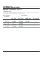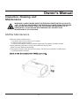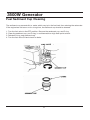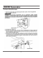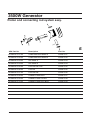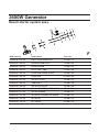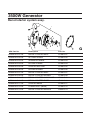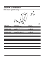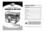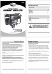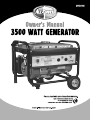
1
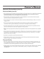
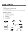
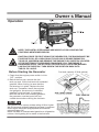
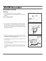
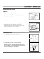
3500W Generator
Topic
Page
Limited Warrant y
3
Sa fet y G u i d e l i n e s
5
G e n e r a l Pr e c a u t i o n s
6
Battery
15
Assembly
16
Operation
17
Spark Plug Service
22
Inspection, Cleaning, Maintenance and Storage
23
Installation
29
Compliance
31
Speci fications
32
G e n e r a l Pa r t s L i s t i n g
33
WARNING! READ AND UNDERSTAND ALL SAFETY PRECAUTIONS
IN THIS MANUAL BEFORE OPERATING. FAILURE TO COMPLY WITH
INSTRUCTIONS IN THIS MANUAL COULD RESULT IN PERSONAL
INJURY, PROPERTY DAMAGE, AND/ OR VOIDING OF YOUR
WARRANTY. ALL-POWER WILL NOT BE LIABLE FOR ANY DAMAGE
BECAUSE OF FAILURE TO FOLLOW THESE INSTRUCTIONS.
2
6^ULY»Z4HU\HS
3PTP[LK>HYYHU[`
(SS7V^LY^HYYHU[Z[V[OLVYPNPUHSW\YJOHZLY^OV\ZLZ[OLWYVK\J[PUHJVUZ\TLY
HWWSPJH[PVUWLYZVUHSYLZPKLU[PHSVYOV\ZLOVSK\ZHNL[OH[HSSWYVK\J[ZJV]LYLK\UKLY[OPZ
^HYYHU[`HYLMYLLMYVTKLMLJ[ZPUTH[LYPHSHUK^VYRTHUZOPWMVYVUL`LHYMYVT[OLKH[LVM
W\YJOHZL(SSWYVK\J[ZJV]LYLKI`[OPZSPTP[LK^HYYHU[`^OPJOHYL\ZLKPUJVTTLYJPHSHWWSPJH[PVUZ
PLPUJVTLWYVK\JPUNHYL^HYYHU[LK[VILMYLLVMKLMLJ[ZPUTH[LYPHSHUK^VYRTHUZOPWMVY
KH`ZMYVT[OLKH[LVMVYPNPUHSW\YJOHZL7YVK\J[ZJV]LYLK\UKLY[OPZ^HYYHU[`PUJS\KLHPY
JVTWYLZZVYZHPY[VVSZZLY]PJLWHY[ZWYLZZ\YL^HZOLYZHUKNLULYH[VYZ
(SS7V^LY^PSSYLWHPYVYYLWSHJLH[(SS7V^LYZVSLVW[PVUWYVK\J[ZVY
JVTWVULU[Z^OPJOOH]LMHPSLK^P[OPU[OL^HYYHU[`WLYPVK:LY]PJL^PSSILZJOLSK\SLKHJJVYKPUN
[V[OLUVYTHS^VYRMSV^HUKI\ZPULZZOV\YZH[[OLZLY]PJLJLU[LYSVJH[PVUHUK[OLH]HPSPIPSP[`VM
YLWSHJLTLU[WHY[Z(SSKLJPZPVUZVM(SS7V^LY^P[OYLNHYK[V[OPZSPTP[LK^HYYHU[`ZOHSSIL
MPUHS
;OPZ^HYYHU[`NP]LZ`V\ZWLJPMPJSLNHSYPNO[ZHUK`V\TH`HSZVOH]LV[OLYYPNO[Z^OPJO]HY`MYVT
Z[H[L[VZ[H[L
9,:765:0)030;@6-690.05(37<9*/(:,9PUP[PHS<ZLY!
;VWYVJLZZH^HYYHU[`JSHPTVU[OPZWYVK\J[+656;YL[\YUP[LT[V[OLYL[HPSLY;OLWYVK\J[T\Z[
ILL]HS\H[LKI`HU(\[OVYPaLK>HYYHU[`:LY]PJL*LU[LY-VY[OLSVJH[PVUVM[OLULHYLZ[(\[OVYPaLK
>HYYHU[`:LY]PJL*LU[LYJHSS 9L[HPUVYPNPUHSJHZOYLNPZ[LYZHSLZYLJLPW[HZWYVVMVMW\YJOHZLMVY^HYYHU[`[V^VYR
<ZLYLHZVUHISLJHYLPU[OLVWLYH[PVUHUKTHPU[LUHUJLVM[OLWYVK\J[HZKLZJYPILKPU[OL6^ULY»Z
4HU\HSZ
+LSP]LYVYZOPW[OLWYVK\J[[V[OL(\[OVYPaLK>HYYHU[`:LY]PJL*LU[LY-YLPNO[JVZ[ZPMHU`T\Z[
ILWHPKI`[OLW\YJOHZLY
0M[OLW\YJOHZLYKVLZUV[YLJLP]LZH[PZMHJ[VY`YLZ\S[ZMVYT[OL(\[OVYPaLK>HYYHU[`:LYJP]L
*LU[LY[OLW\YJOZLYZOV\SKJVU[HJ[(SS7V^LY
3500W Generator
(Example: Battery, Spark Plug,Air Filter)
Owner’s Manual
Safety Guidelines - Definitions
This manual contains important information that you need to know and
understand in order to protect YOUR SAFETY and to PREVENT
EQUIPMENT PROBLEMS. The following symbols help you recognize this
information. Please read the manual and pay attention to these sections.
Save These Important Safety Instructions!
Read and understand all of these safety instructions. Be
sure to retain them for future use.
WARNING! WARNINGS INDICATE A CERTAINTY OR STRONG
POSSIBILITY OF PERSONAL INJURY OR DEATH IF
INSTRUCTIONS ARE NOT FOLLOWED.
CAUTION: CAUTIONS INDICATE A POSSIBILITY OF
EQUIPMENT DAMAGE IF INSTRUCTIONS ARE NOT
FOLLOWED.
NOTE: NOTES GIVE HELPFUL INFORMATION
WARNING! IMPROPER OPERATION OR MAINTENANCE
OF THIS PRODUCT COULD RESULT IN SERIOUS INJURY
AND PROPERTY DAMAGE. READ AND UNDERSTAND ALL
WARNINGS AND OPERATING INSTRUCTIONS BEFORE USING
THIS EQUIPMENT. WHEN USING AIR TOOLS, BASIC SAFETY
PRECAUTIONS SHOULD ALWAYS BE FOLLOWED TO REDUCE
THE RISK OF PERSONAL INJURY.
5
3500W Generator
General Precautions
WARNING! FAILURE TO FOLLOW THESE INSTRUCTIONS CAN RESULT IN
SEVERE INJURY OR DEATH.
CAUTION: FAILURE TO FOLLOW THESE INSTRUCTIONS CAN ALSO
RESULT IN DAMAGE TO THE TOOL AND/OR THE ITEM YOU ARE WORKING
ON.
DANGER
CARBON MONOXIDE
Using a generator indoors WILL KILL YOU IN MINUTES.
Generator exhaust contains high levels of carbon monoxide (CO), a poisonous gas you cannot
see or smell. If you can smell the generator exhaust, you are breathing CO. But even If you
cannot smell the exhaust, you could be breathing CO.
· NEVER use a generator inside homes, garages, crawlspaces, or other partly enclosed areas.
Deadly levels of carbon monoxide can build up in these areas. Using a fan or opening windows
and doors does NOT supply enough fresh air.
· ONLY use a generator outdoors and far away from open windows, doors, and vents. These
openings can pull in generator exhaust.
Even when you use a generator correctly, CO may leak into the home. ALWAYS use a batterypowered or battery-backup CO alarm in the home.
If you start to feel sick, dizzy, or weak after the generator has been running, move to fresh air
RIGHT AWAY. See a doctor. You could have carbon monoxide poisoning.
WARNING! THE EXHAUST CONTAINS POISONOUS CARBON MONOXIDE
GAS THAT CAN CAUSE LOSS OF CONSCIOUSNESS AND MAY LEAD TO
DEATH.
Gasoline and Oil
This product requires oil and fuel. Attempting to start the engine without oil will ruin
the engine and void the warranty. Work in well ventilated area. Keep cigarettes,
flames or sparks away from the work area or where gasoline is stored.
WARNING! GASOLINE IS EXTREMELY FLAMMABLE AND IS EXPLOSIVE
UNDER CERTAIN CONDITIONS. KEEP OUT OF REACH OF CHILDREN.
• Gasoline fuel and fumes are flammable and potentially explosive. Use proper fuel storage and
handling procedures. Always have multiple ABC class fire extinguishers nearby.
• Keep the generator and surrounding area clean at all times.
6
Owner’s Manual
• Fuel or oil spills must be cleaned up immediately. Dispose of fluids and cleaning materials as per
any local, state, or federal codes and regulations. Store oily rags in a covered metal container.
• Never store fuel or other flammable materials near the generator.
General Precautions (cont’d)
Gasoline and Oil (cont’d)
• Do not smoke, or allow sparks, flames or other sources of ignition around the engine and fuel
tank. Fuel vapors are explosive.
• Keep grounded conductive objects, such as tools, away from exposed, live electrical parts and
connections to avoid sparking or arcing. These events could ignite fumes or vapors.
• Do not refill the fuel tank while the engine is running or while the engine is still hot. Do not
operate the generator with known leaks in the fuel system
• Excessive buildup of unburned fuel gases in the exhaust system can create a potentially
explosive condition. This buildup can occur after repeated failed start attempts, valve testing, or
hot engine shutdown. If this occurs, open exhaust system drain plugs, if equipped, and allow the
gases to dissipate before attempting to restart the generator.
• Use only engine manufacturer recommended fuel and oil.
Fuel:
Fuel capacity is 4 US gallons(15 L). Use regular
unleaded gasoline with a minium octane rating of 85.
Oil:
Oil capacity is 0.63 qt(0.6 L)
Hot Components
WARNING! ENGINE AND EXHAUST SYSTEM PARTS BECOME VERY
HOT AND REMAIN HOT FOR SOME TIME AFTER THE ENGINE IS RUN. WEAR
INSULATED GLOVES OR WAIT UNTIL THE ENGINE AND EXHAUST SYSTEM
HAVE COOLED BEFORE HANDLING THESE PARTS.
Power Output
This generator is not designed to power sensitive electronic equipment (including computers
and medical devices) without the addition of an approved line conditioner, which is sold separately.
CAUTION: ATTEMPTING TO POWER SENSITIVE ELECTRONIC EQUIPMENT
WITHOUT THE USE OF AN APPROVED LINE CONDITIONER MAY CAUSE
DAMAGE TO THE EQUIPMENT. ALL-POWER IS NOT RESPONSIBLE
FOR ANY DIRECT OR INDIRECT DAMAGE CAUSED BY FAILURE TO USE AN
APPROVED LINE CONDITIONER.
7
3500W Generator
General Precautions (cont’d)
Work Area
• Keep your work area clean and well lit. Cluttered benches and dark areas invite accidents.
• Do not operate power tools in explosive atmospheres, such as in the presence of flammable
liquids, gases, or dust. Generators create sparks which may ignite the dust or fumes.
• Keep bystanders, children, and visitors away while operating a generator. Provide barriers or
shields as needed.
Electrical Safety
• Grounded tools must be plugged into an outlet properly installed and
grounded in accordance with all codes and ordinances. Never remove the
grounding prong or modify the plug in any way. Do not use any adapter
plugs.
• Grounding provides a low-resistance path to carry electricity away from the
user in the event of an electrical malfunction.
• Double insulated tools are equipped with a polarized plug where one blade is wider than the
other. This plug fits in a polarized outlet only one way. If the plug does not fit fully in the outlet,
reverse the plug. If it still does not fit, contact a qualified electrician to install a polarized outlet.
Do not change the plug in any way. Double insulation eliminates the need for the three-wire
grounded power cord and grounded power supply system.
• Avoid body contact with grounded surfaces such as pipes, radiators, ranges, and refrigerators.
There is an increased risk of electric shock if your body is grounded.
• Do not expose generator to rain or wet conditions. Water entering a generator will increase the
risk of electric shock.
• Do not abuse the power cord. Keep power cords away from heat, oil, sharp edges, or moving
parts. Replace damaged power cords immediately. Damaged power cords increase the risk of
electric shock.
• When operating a power tool outside, use an outdoor extension cord marked “W-A” or “W”.
These extension cords are rated for outdoor use, and reduce the risk of electric shock.
8
Owner’s Manual
General Precautions (cont’d)
Electrical Safety (cont’d)
• All connections and conduits from the generator to the load must only be installed by trained and
licensed electricians, and in compliance with all relevant local, state, and federal electrical
codes and standards, and other regulations where applicable.
• The generator must be earth-grounded for fixed installations in accordance with all relevant
electrical codes and standards before operation.
• Do not attempt to connect or disconnect load connections while standing in water, or on wet or
soggy ground.
• Do not touch electrically energized parts of the generator and interconnecting cables or
conductors with any part of the body, or with any non-insulated conductive object.
• Connect the generator only to a load or electrical system (120 volt) that is compatible with the
electrical characteristics and rated capacities of the generator.
• Before servicing equipment powered by the generator, disconnect the equipment from its power
input.
• Keep all electrical equipment clean and dry. Replace any wiring where the insulation is cracked,
cut abraded or otherwise degraded. Replace terminals that are worn, discolored, or corroded.
Keep terminals clean and tight.
• Insulate all connections and disconnected wires.
• Guard against electric shock. Prevent body contact with grounded surfaces such as pipes,
radiators, ranges, and refrigerator enclosures.
Personal Safety
• Stay alert. Watch what you are doing, and use common sense when operating a generator. Do
not use generator while tired or under the influence of drugs, alcohol, or medication. A moment
of inattention while operating generators may result in serious personal injury.
• Dress properly. Do not wear loose clothing or jewelry. Contain long hair. Keep your hair, clothing,
and gloves away from moving parts. Loose clothes, jewelry, or long hair can be caught in
moving parts.
9
3500W Generator
General Precautions (cont’d)
Personal Safety (cont’d)
• Avoid accidental starting. Make sure the power switch is in its “OFF” position, and disconnect
the spark plug wire when not in use.
• Remove adjusting keys or wrenches before turning the generator on. A wrench or a key that is
left attached to a rotating part of the generator may result in personal injury.
• Do not overreach. Keep proper footing and balance at all times.
• Use safety equipment. Always wear eye protection. Wear ANSI approved safety impact eye
goggles. Dust mask, non-skid safety shoes, hard hat, or hearing protection must be used for
appropriate conditions.
• Do not force the generator. Use the correct generator for your application. The correct generator
will do the job better and safer at the rate for which it is designed.
• Do not use the generator if the power switch does not turn it on or off. Any generator that cannot
be controlled with the power switch is dangerous and must be replaced.
Generator Use and Care
Make sure the power switch is in its “OFF” position and disconnect the spark plug wire before
making any adjustment, changing accessories, or storing the generator. Such preventive safety
measures reduce the risk of starting the generator accidentally.
Store idle generators out of reach of children and other untrained persons. Generators are
dangerous in the hands of untrained users.
Maintain generators with care. Do not use damaged generator. Tag damaged generators “Do not
use” until repaired.
Check for misalignment or binding of moving parts, breakage of parts, and any other condition that
may affect the generator’s operation. If damaged, have the generator serviced before using. Many
accidents are caused by poorly maintained generators.
Use only accessories that are recommended by the manufacturer for your model. Accessories that
may be suitable for one generator may become hazardous when used on another generator.
10
Owner’s Manual
General Precautions (cont’d)
Servicing
Maintain labels and name plates on the generator and engine. These carry important information.
If unreadable or missing, contact our service center toll free at 888-896-6881 immediately for a
replacement.
Generator service must be performed only qualified repair personnel. Service or maintenance
performed by unqualified personnel could result in a risk of injury.
When servicing a generator, use only identical replacement parts. Follow all appropriate
instructions in this manual. Use of unauthorized parts or failure to follow maintenance instructions
may create a risk of electric shock or injury.
Heart Pacemakers
WARNING! PEOPLE WITH PACEMAKERS SHOULD CONSULT THEIR
PHYSICIAN(S) BEFORE USING THIS PRODUCT. ELECTROMAGNETIC
FIELDS IN CLOSE PROXIMITY TO A HEART PACEMAKER COULD CAUSE
INTERFERENCE TO OR FAILURE OF THE PACEMAKER.
Installation
• Ensure installation meets all applicable safety, and local and national electrical codes. Have
installation performed by a qualified, licensed electrician and building contractor.
• All electrical work, including the earth-ground connection, should be completed by a licensed
electrician.
• Any separate fuel storage or generator supply facility must be built or installed in full compliance
with all relevant local, state, and federal regulations.
11
3500W Generator
General Precautions (cont’d)
Installation (cont’d)
• If the generator is installed outdoors, it must be weatherproofed and should be soundproofed. It
should not be run outdoors without protection to the generator and wiring conduit.
• The generator weighs 100 lbs (approx). Two or more people should assist when moving or lifting
this product. Never lift the generator using the engine or alternator lifting lugs. Connect lifting
equipment to the frame of the generator
• Before lifting the generator, ensure the lift rigging and supporting structure are in good
condition, and are rated to lift such a load.
• Keep all personnel away from the suspended generator during relocating.
• The supporting floor/ground surface should be level and strong enough to safely hold the weight
of the generator. If the floor/grounded surface is not level, strong cross members should be
placed under the full length of the generator frame at its low side.
• For trailer installation, the generator should be mounted on the center point of the trailer, over
the wheels. The trailer must be capable of supporting the weight of the generator and all
contents (tools, etc.)
• Install sound-and weather-proofing only when it is not raining or snowing to avoid trapping
moisture within the generator’s area.
Mechanical
• Always make sure the power switch is in its “OFF” position. Disconnect the spark plug wire, and
allow the engine to completely cool before carrying out maintenance.
• Check for damaged parts. Before using the generator, any part that appears damaged should
be carefully checked to determine that it will operate properly and perform its intended function.
Check for alignment and binding of moving parts, any broken parts or mounting fixtures, and any
other condition that may affect proper operation technician.
• The generator is designed with guards for protection from moving parts. In any case, care must
still be taken to protect personnel and equipment from other mechanical hazards when working
around the generator.
12
Owner’s Manual
General Precautions (cont’d)
Mechanical (cont’d)
• Do not operate the generator with safety guards removed. While the generator is running, do not
attempt to reach around the safety guard for maintenance or any other reason.
• Keep hands, arms, long hair, loose clothing, and jewelry away from moving parts. Be aware that
when engine parts are moving fast they cannot be seen clearly.
• Keep access doors on enclosures closed and locked when access is not required.
• When working on or around the generator always wear protective clothing including ANSI
approved safety gloves, safety eye goggles, and safety hat.
• Do not alter or adjust any part of the generator that is assembled and supplied by the
manufacturer.
• Always follow and complete scheduled engine and generator maintenance.
Chemicals
• Avoid contact with hot fuel, oil, exhaust fumes, and hot solid surfaces.
• Avoid body contact with fuels, oils, and lubricants used in the generator. If swallowed, seek
medical treatment immediately. Do not induce vomiting if fuel is swallowed. For skin contact,
immediately wash with soap and water. For eye contact, immediately flush eyes with clean water
and seek medical attention.
Noise
• Prolonged exposure to noise levels above 68 DBA is hazardous to hearing. Always wear ANSI
approved ear protection when operating or working around the generator when it is running.
13
3500W Generator
General Precautions (cont’d)
Extension Cord
If an extension cord (not included) is used, make sure to use only UL approved cords having the
correct gauge and length according to the following table:
Name plate Amps
(@ full load)
Cord L e ngths
0 ft.- 50 ft.
50 ft.-100 ft.
0-5
5.1 - 8
16 AWG
16 AWG
16 AWG
14 AWG
8.1 - 12
12.1 - 15
15 - 20
14 AWG
12 AWG
10 AWG
12 AWG
10 AWG
10 AWG
14
100 ft.-150 ft.
12 AWG
10 AWG
-
150 ft.-200 ft.
12 AWG
-
Owner’s Manual
Battery
This product does not need a battery.
15
3500W Generator
Assembly
Unpacking
1. Remove the generator and loose parts box from the carton.
2. Compare the accessory with the inventory list below.
Loose Parts (Wheel kit and handle)
Check all loose parts against the following list. Contact your dealer toll free at 888.896.6881
if any of the loose parts shown are not included with your generator
Hardware Check:
Your Hardware Kit should include:
1)
1 Handle with bolt and bracket
2)
6 (six) axle shaft bolts and nuts
3)
2 (two) 8mm bolts, (6mm x 1.0) thread
4)
2 (two) 10mm Nuts (6mm x 1.0) thread
5)
2 (two) rubber bushings with 2 nuts
6)
2 (two) axle shaft
7)
2 (two) washers
8)
2 (two) cotter pins
9)
4 (four) leg bolts and nuts
10)
1 (one) generator leg
11)
2 (two) wheels (not shown)
5
2
7
6
1
8
3
4
9
16
10
Owner’s Manual
Operation
NOTE: THE PARTS LISTED ABOVE ARE HELPFUL FOR LOCATING THE
CONTROLS MENTIONED BELOW.
CAUTION: PRIOR TO FIRST USING THE GENERATOR, THE ENGINE MUST BE
FILLED WITH OIL OF A HIGH QUALITY SAE 10W-30 GRADE ENGINE OIL.
TO DO SO, UNSCREW AND REMOVE THE ENGINE’S OIL DIPSTICK LOCATED
AT THE BOTTOM OF THE ENGINE CRANKCASE. FILL THE ENGINE’S
CRANKCASE UNTIL THE OIL LEVEL IS LEVEL WITH THE UPPER MARKED
LINE ON THE DIPSTICK. THEN SCREW THE DIPSTICK BACK INTO
THE OIL FILL HOLE.
Before Starting the Generator
Fuel tank capacity:15.0L(4 gallons)
1. Check that the engine power switch is in its
“OFF” position.
2. Before the first use, remove the fuel
tank cap and fill the fuel tank with unleaded
gasoline. When fueling, be sure that the
fuel strainer is in place. Replace the fuel
tank cap. Thereafter, check the engine’s
fuel gauge for the amount of unleaded
gasoline in the fuel tank. If necessary,
refill the fuel tank with unleaded gasoline;
the generator must be turned off and
cooled down before refilling the fuel tank.
Use gasoline with a pump octane rating of 86 or higher.
We recommend unleaded gasoling because it produces
fewer engine and spark plug deposits and extends
exhaust system life.
Never use stale or contaminated gasoline or oil/gasoline
mixture. Avoid getting dirt or water in the fuel tank.
17
Operation (cont’d)
Starting
1. Turn the engine switch to the ON position.
The engine switch enables and disables the ignition
system.
OFF: To stop the engine
ON: To run the engine
2. The fuel valve is located under the fuel tank . When
the valve lever is in the ON position, fuel is allowed
to flow from the fuel tank to the carburetor. Be sur
to return the fuel valve lever to the OFF position after
stopping the engine.
Choke Lever
Fuel Valve
OFF
Open
Close
3. To start a cold engine, move the choke lever to the
CLOSED position. To restart a warm engine, leave the
choke lever in the OPEN position.
The choke lever opens and closes the choke valve in
the carburetor.
The CLOSED position enriches the fuel mixture from
starting a cold engine.
The OPEN position provides the correct fuel mixture
for operation after starting, and for restarting a warm
engine.
18
ON
Owner’s Manual
Operation (cont’d)
Starting
4. Operate the Recoil Starter:
Pull the starter grip lightly until you feel resistance,
then pull briskly. Return the starter grip gently.
Pulling the starter grip operates the recoil starter to
crank the engine
Starter Grip
5. If the choke has been moved to the CLOSED
position to start the engine, gradually move it to the
OPEN position as the engine warms up.
Stopping Engine
1. Turn the engine switch to the OFF position.
ON
OFF
Engine
Switch
2. Turn the fuel valve lever to the OFF position.
When the engine is not in use, leave the fuel valve in
the OFF position to prevent carburetor flooding and to
reduce the possibility of fuel leakage.
19
3500W Generator
Operation (cont’d)
Powering 120 Volt AC Tools And Equipment:
1. Prior to powering tools and equipment, make sure the generator’s rated voltage, and amperage
capacity (120 V AC @ 25 AMPs) is adequate to supply all electrical loads that the unit will
power. If powering exceeds the generator’s capacity, it may be necessary to group one or more
of the tools and/or equipment for connection to a separate generator.
CAUTION: ATTEMPTING TO POWER SENSITIVE ELECTRONIC EQUIPMENT
WITHOUT THE USE OF AN APPROVED LINE CONDITIONER MAY CAUSE
DAMAGE TO THE EQUIPMENT. ALL-POWER IS NOT RESPONSIBLE FOR
ANY DIRECT OR INDIRECT DAMAGE CAUSED BY FAILURE TO USE AN
APPROVED LINE CONDITIONER.
2. Once the generator is running, simply connect the power cords of 120 volt AC powered
tools and equipment into the 120 volt AC dual outlets.
NOTE: THE GENERATOR FEATURES AN AC NON-FUSE THERMAL PROTECTOR
TO PROTECT THE AC CIRCUIT IN CASE OF AN OVERLOAD. SHOULD
AN OVERLOAD OCCUR, THE BREAKER WILL POP.
3. Disconnect all electrical powered tools and equipment from the generator’s 120 volt AC
duel outlets.
4. After the engine and generator have completely cooled, store generator in a safe, clean, dry
location (if not already installed).
20
Owner’s Manual
Operation (cont’d)
Powering 12 Volt DC tools and Equipment:
1. Prior to powering tools and equipment, make sure the generator’s rated voltage, and amperage
capacity (12V DC) is adequate to supply all electrical loads that the unit will power. If powering
exceeds the generator’s capacity, it may be necessary to group one or more of the tools and/or
equipment for connection to a separate generator.
2. Connect the power cord of a 12 VDC powered tool or equipment to the DC Terminals.
CAUTION: MAKE SURE TO CONNECT THE POSITIVE (+) LEAD OF THE
POWER CORD TO THE POSITIVE (+) TERMINAL ON THE GENERATOR,
AND CONNECT THE NEGATIVE (-) LEAD OF THE POWER CORD TO THE
NEGATIVE (-) TERMINAL ON THE GENERATOR.
THE 12V DC IS FOR BATTERY CHARGING ONLY.
21
3500W Generator
Spark Plug Service
In order to service the spark plug, you will need a spark plug wrench (commercially available).
Recommended spark plugs: NHSP LD F7TC , we recommend our OEM spark plug.
To ensure proper engine operation, the spark plug must be properly gapped and free of deposits.
1. Remove the spark plug cap.
2. Clean any dirt from around the spark plug base.
3. Use a spark plug wrench to remove the spark plug.
4. Visually inspect the spark plug. Discard it if the insulator is cracked or chipped. Clean the spark
plug with a wire brush if it is to be reused.
5. Measure the plug gap with a feeler gauge.(Correct as necessary by carefully bending the side electrode.)
The gap should be : 0.70-0.80 mm (0.028-0.031in)
6. Check that the spark plug washer is in good condition.
7. After the spark plug is seated, tighten with a spark plug in by hand to prevent cross-threading.
8 . After the spark plug is seated, tighten with a spark plug wrench to compress the washer.
NOTE: THE SPARK PLUG MUST BE SECURELY TIGHTENED. AN IMPROPERLY
TIGHTENED SPARK PLUG CAN BECOME VERY HOT AND COULD DAMAGE THE
ENGINE. NEVER USE SPARK PLUGS WHICH HAVE AN IMPROPER HEAT RANGE.
USE ONLY RECOMMENDED SPARK PLUS OR EQUIVALENT.
22
Owner’s Manual
Inspection, Cleaning, and
Maintenance
WARNING! ALWAYS MAKE SURE THE ENGINE POWER SWITCH (2) IS IN ITS
“OFF” POSITION. DISCONNECT THE SPARK PLUG WIRE FROM THE ENGINE.
AND ALLOW SUFFICIENT TIME FOR THE ENGINE AND GENERATOR TO
COMPLETELY COOL BEFORE PERFORMING ANY INSPECTIONS,
MAINTENANCE, OR CLEANING.
Muffler Maintenance
• Spark arrestor maintenance:
1. Unscrew screw from the end of muffler.
2. Remove the spark arrestor.
3. Use a wire brush to remove carbon deposits from spark arrestor screen
• If the generator has been running, the muffler will be very hot.
Allow it to cool before proceeding.
• The spark arrestor must be serviced every 100 hours to maintain its efficiency.
4. Reinstall spark arrestor.
23
3500W Generator
Fuel Sediment Cup Cleaning
The sediment cup prevents dirt or water which may be in the fuel tank from entering the carburetor.
If the engine has not been run for a long time, the sediment cup should be cleaned.
1. Turn the fuel valve to the OFF position. Remove the sedement cup, and O-ring.
2. Clean the sediment cup, and O-ring, in nonflammable or high flash point solvent.
3. Reinstall O-ring, and sediment cup.
4. Turn the fuel valve ON and check for leaks.
24
Owner’s Manual
Maintenance Guide
Periodic maintenance and adjustment is necessary to keep the generator in good operating
condition.
WARNING! Exhaust gas contains poisonous carbon monoxide. Shut off the engine before
performing any maintenance. If the engine must be run, make sure the areas is well ventilated.
• Before each use, inspect the generator. Check for:
-
Loose screws
-
Misaligned or binding moving parts
-
Cracked or broken parts
-
Damaged electrical wiring
-
Any other condition that may affect safe operation.
• If an engine problem occurs, have it checked by a qualified service technician before further use.
Do not use damaged equipment.
• Before each use, make sure the engine’s oil and gas levels are adequate. If necessary, fill the
crankcase until the oil level is even with the oil hill hole and/or fill the fuel tank.
• Before each use, remove all debris with a soft brush, rag, or vacuum.
• Lubricate all moving parts using a premium
quality, lightweight machine oil.
• Every 50 hours of use, drain the old engine oil
and replace with a high a high quality
SAE 10W-30 grade engine oil.
• Every 300 hours of use, have a qualified, certified
technician perform thorough maintenance on the
generator and engine.
• For long term storage, either drain fuel into
suitable container or add a fuel preservative/
stabilizer (not included) to prevent fuel
breakdown.
25
Upper Level
3500W Generator
Air cleaner service
A dirty air cleaner will restrict air flow to the carburetor. To prevent carburetor malfuncion, service
the air cleaner regularly. Service more frequently when operating the generator in extremely dusty
areas.
WARNING! Using gasoline or flammable solvent to clean the filter element
can cause a fire or explosion. Use only soapy water or nonflammable
solvent.
NOTE: Never run the generator without the air cleaner. Rapid engine wear
will result.
1. Unsnap the air cleaner cover clips, remove the air
cleaner cover, and remove the element.
2. Wash the element in a solution of household detergent
and warm water, then rinse thoroughly, or wash in
nonflammable or high flash point solvent. Allow the
element to dry thorughly.
3. Soak the element in clean engine oil and squeeze
out the excess oil. The engine will smoke during
initial start-up if too much oil is left in the element.
4. Reinstall the air cleaner element and the cover.
26
Owner’s Manual
27
3500W Generator
Transporting/Storage
28
Owner’s Manual
Installation
NOTE: PRIOR TO POWERING TOOLS AND EQUIPMENT MAKE SURE THE
GENERATOR’S RATED VOLTAGE, WATTAGE AND AMPERAGE CAPACITY IS
ADEQUATE TO SUPPLY ALL ELECTRICAL LOADS THAT THE UNIT WILL
POWER. IF POWERING EXCEEDS THE GENERATOR’S CAPACITY, IT MAY BE
NECESSARY TO GROUP ONE OR MORE OF THE TOOLS AND/OR EQUIPMENT
FOR CONNECTION TO A SEPARATE GENERATOR.
Electrical and other permits may be required for the installation of emergency power systems.
Investigate your local building and electrical codes before installing this unit. Installation must be
completed by licensed contractors.
WARNING! THE GENERATOR WEIGHS APPROXIMATELY 100 POUNDS. USE
CARE AND THE PROPER LIFTING OR HOISTING EQUIPMENT WHEN MOVING
IT TO THE INSTALLATION LOCATION. ALWAYS CONNECT HOIST LINES TO
THE FRAME OF THE GENERATOR.
General Location
• Make sure to locate and install the generator outdoors where cooling air is readily available.
• Install the generator so that the air inlets and outlets are not blocked by obstructions such as
bushes, trees, or snow drifts. Locating it in the path of heavy winds or snowdrifts may require
the placement of a barrier for protection. In normal weather conditions, the air vent should face
the prevailing wind direction.
• Install the generator on a concrete slab or other area where rain drainage or flood waters can
not reach it.
• Generator placement should allow four feet of access to all sides for maintenance.
• Place the generator as close as possible to the electrical tools and equipment being powered to
reduce the length of extension cords.
29
3500W Generator
Installation (cont’d)
Supporting and Mounting
Mount the generator on a concrete slab capable of supporting the weight of the generator. The
slab must extend on all sides beyond the frame by at least one foot. Contact a cement contractor
for slab specifications if necessary. Attach the frame to the concrete slab using 3/8” diameter
expansion anchor bolts (not supplied).
Grounding
NOTE: IT IS RECOMMENDED THAT ONLY A TRAINED AND LICENSED
ELECTRICIAN PERFORM THIS PROCEDURE
Connect a #6 AWG grounding wire (not included) from the ground connector (8) on the generator
to a grounding rod (not included) that has been driven at least 24 inches deep into the earth. The
grounding rod must be an earth-driven copper or brass rod (electrode) which can adequately
ground the generator.
30
3500W Generator
Compliance
You should get a Certificate of EPA while you purchased this product.
31
Owner’s Manual
Specifications
AC electrical
Cur rent O ut p ut
120V AC @ 25A 6 0Hz
Continuous/rated Wattage
3,000
Peak Wat tage
3.500
O u t l et
2 120V AC, 3 spring grounded
DC electrical
Current output
12V DC @ 8.3A
Gasoline engine
Type
4-cycle OHV air-cooled recoil start
Dis plac ement
196c c
O il c a pac it y
0.63 quart (0.6 liter)
EPA approved
ye s
Fuel
Type
U n l ea d e d g a s o l i n e
Ca p a c i t y
4 gallons (15 liters)
Run n i n g t i m e
8 hours /half load (approx.)
Fuel gauge
inc luded
Approximate weight
107 lbs.
Weight
32
3500W Generator
Cylinder head system assy.
APA Part No.
Description
Part No.
APG3012-A-01-JD
CYLINDER HEAD COMP.
JF200-A-01
APG3012-A-02-JD
EX. VALVE GUIDE
JF168-A-02
APG3012-A-03-JD
IN. VALVE GUIDE
JF168-A-03
APG3012-A-04-JD
VALVE GUIDE CLIP
JF168-A-04
APG3012-A-05-JD
CYLINDER HEAD SEALING PAD
JF200-A-05
APG3012-A-06-JD
HEAD COVER COMP.
JF168-A-06
APG3012-A-07-JD
HEAD COVER PACKING
JF168-A-07
APG3012-A-08-JD
TUBE
JF168-A-08B
APG3012-A-09-JD
HEAD COVER COMP. BOLT MX12
JF168-A-09
APG3012-A-10-JD
CARBURETOR STUD BOLT
JF168-A-10B
APG3012-A-11-JD
EXHAUST PIPE STUD BOLT
JF168-A-11
APG3012-A-12-JD
DOWEL PIN (10X16)
JF168-A-12
APG3012-A-13-JD
FLANGE BOLT (M8X58)
JF168-A-12
APG3012-A-14-JD
SPARK PLUG
JF168-A-12
33
A
3500W Generator
Cylinder barrel
APA Part No.
Description
Part No.
APG3012-B-01-JD
CRANK CASE
JF200-B-01
APG3012-B-02-JD
OIL LEVEL SWITCH ASSY.
JF168-B-02
APG3012-B-03-JD
GOVERNOR GEAR ASSY.
JF168-B-03
APG3012-B-04-JD
SLIDER SHAFT
JF168-B-02
APG3012-B-05-JD
GOVERNOR ARM SHAFT
JF168-B-02
APG3012-B-06-JD
LOCK PIN (8mm)
JF168-B-04
APG3012-B-07-JD
WASHER
JF168-B-05
APG3012-B-08-JD
DRAIN PLUG BOLT
JF168-B-06
APG3012-B-09-JD
THRUST WASHER (6mm)
JF168-B-07
APG3012-B-10-JD
DRAIN PLUG WASHER (10.2mm)
JF168-B-08
APG3012-B-11-JD
SLIDER WASHER
JF168-B-09
APG3012-B-12-JD
BALL BEARING (6205)
JF168-B-10
JF168-B-11
APG3012-B-14-JD
OIL ALERT
JF168-B-12
APG3012-B-15-JD
FLANGE NUT (M10) and O-RING
JF168-B-13
APG3012-B-16-JD
GOVERNOR SLIDER
JF168-B-13
APG3012-B-17-JD
FLANGE BOLT (M6X12)
JF168-B-13
34
B
3500W Generator
Crankcase cover system assy.
APA Part No.
Description
Part No.
APG3012-C-01-JD
CRANKCASE COVER
JF168-C-01B
APG3012-C-02-JD
CRANKCASE COVER PAD
JF168-C-02
APG3012-C-03-JD
OIL SCALE
JF168-C-03
APG3012-C-04-JD
OIL SCALE SEAL
JF168-C-04
35
C
3500W Generator
Crankshaft system assy.
APA Part No.
Description
Part No.
APG3012-D-01-JD
CRANKSHAFT COMP.
JF200-D-01
APG3012-D-02-JD
SEMICIRCLE KEY
JF168-D-02
36
D
3500W Generator
Piston and connecting rod system assy.
APA Part No.
Description
Part No.
APG3012-E-01-JD
COMPRESSION RING A
JF200-E-01
APG3012-E-02-JD
COMPRESSION RING B
JF200-E-02
APG3012-E-03-JD
OIL RING A
JF200-E-03
APG3012-E-04-JD
OIL RING B
JF200-E-04
APG3012-E-05-JD
PISTON PIN CLIP
JF200-E-05
APG3012-E-06-JD
PISTON
JF200-E-05
APG3012-E-07-JD
PISTON PIN
JF200-E-06
APG3012-E-08-JD
CONNECTING ROD
JF200-E-07
APG3012-E-09-JD
CONNECTING COVER
JF200-E-08
APG3012-E-10-JD
CONNECTING ROD BOLT
JF200-E-09
37
E
3500W Generator
Recoil starter system assy.
APA Part No.
Description
Part No.
APG3012-F-01-JD
PIVOT ADJUSTING NUT
JF168-F-01
APG3012-F-02-JD
ROCKER ARM PIVOT
JF168-F-02
APG3012-F-03-JD
ROCKER ARM
JF168-F-03
APG3012-F-04-JD
PIVOT BOLT (M8)
JF168-F-04
APG3012-F-05-JD
PUSH ROD GUIDE PLATE
JF168-F-05
APG3012-F-06-JD
PUSH ROD
JF168-F-06
APG3012-F-07-JD
VALVE LIFTER
JF168-F-07
APG3012-F-08-JD
CAMSHAFT
JF168-F-08
APG3012-F-09-JD
VALVE ROTATOR
JF168-F-09
APG3012-F-10-JD
EX. VALVE SPRING RETAINER
JF168-F-10
APG3012-F-11-JD
VALVE SPRING
JF168-F-11
APG3012-F-12-JD
IN. VALVE SPRING RETAINER
JF168-F-12
APG3012-F-13-JD
IN. VALVE
JF168-F-13
APG3012-F-14-JD
EX. VALVE
JF168-F-14
38
F
3500W Generator
Recoil starter system assy.
1
APA Part No.
Description
Part No.
APG3012-G-01-JD
RECOIL STARTER ASSY.
JF168-G-01
APG3012-G-02-JD
SETTING SCREW
JF168-G-02
APG3012-G-03-JD
SPRING RETAINER
JF168-G-03
APG3012-G-04-JD
PLATEN SPRING
JF168-G-04
APG3012-G-05-JD
STARTER RATCHET
JF168-G-05
APG3012-G-06-JD
RETURN SPRING
JF168-G-06
APG3012-G-07-JD
RECOIL STARTER REEL
JF168-G-07
APG3012-G-08-JD
RECOIL STARTER SPRING
JF168-G-08
APG3012-G-09-JD
RECOIL STARTER CASE COMP.
JF168-G-09
APG3012-G-10-JD
RECOIL STARTER ROPE
JF168-G-10
APG3012-G-11-JD
STARTER KNOB
JF168-G-11
APG3012-G-12-JD
FLANGE BOLT (M6X8)
JF168-G-12
APG3012-G-13-JD
RECOIL STARTER SPACER
JF200-G-13
39
G
3500W Generator
Fan cover system assy.
3
APA Part No.
Description
Part No.
APG3012-H-01-JD
FAN COVER COMP.
JF168-H-01
APG3012-H-02-JD
FLYWHEEL SIDE PLATE
JF168-H-02
APG3012-H-03-JD
SHROUD
JF168-H-03
APG3012-H-04-JD
AIR CLEANER SUPPORT
JF168-H-04
APG3012-H-05-JD
FLANGE BOLT (M6 X 12)
JF168-H-05
APG3012-H-06-JD
FLANGE BOLT (M6 X 16)
JF168-H-06
40
H
3500W Generator
Carburetor system assy.
1
2
3
4
APA Part No.
Description
Part No.
APG3012-I-01-JD
CARBURETOR ASSY.
JF200-I-01B
APG3012-I-02-JD
CARBURETOR PAPER GASKET
JF168-I-02
APG3012-I-03-JD
CARBURETOR INSULATING PLATE JF200-I-03B
APG3012-I-04-JD
INTAKE PIPE GASKET
41
JF168-I-04
I
3500W Generator
Flywheel system assy.
2
2
APA Part No.
Description
Part No.
APG3012-J-01-JD
FLYWHEEL
JF168-J-01A
APG3012-J-02-JD
FLANGE BOLT (M6 X 25)
JF168-J-02
APG3012-J-03-JD
COOLING FAN
JF168-J-03
APG3012-J-04-JD
STARTER PULLEY
JF168-J-04
APG3012-J-05-JD
FLYWHEEL NUT (M16)
JF168-J-05
APG3012-J-06-JD
STOP SWITCH CORD
JF168-J-06
APG3012-J-07-JD
IGNITION COIL ASSY.
JF168-J-07
APG3012-J-08-JD
SPARK PLUG CAP ASSY.
JF168-J-08
42
J
3500W Generator
Control system assy.
APA Part No.
Description
Part No.
APG3012-M-01-JD
CONTROL UNIT ASSY.
JF168-M-01B
APG3012-M-02-JD
CONTROL BASE COMP.
JF168-M-02B
APG3012-M-03-JD
CONTROL A JUSTING SPRING
JF168-M-03
APG3012-M-04-JD
PAN SCREW (M5 X 34)
JF168-M-04
APG3012-M-05-JD
FLANGE BOLT (M6 X 14)
JF168-M-05
APG3012-M-06-JD
GOVERNOR SPRING
JF168-M-06
APG3012-M-07-JD
THROTTLE RETURN SPRING
JF168-M-07
APG3012-M-08-JD
GOVERNOR ROD
JF168-M-08
APG3012-M-09-JD
FLANGE NUT (M6)
JF168-M-09
APG3012-M-10-JD
GOVERNOR ARM BOLT (M6)
JF168-M-10
APG3012-M-11-JD
GOVERNOR ARM
JF168-M-11
43
M
3500W Generator
Muffler system assy.
APA Part No.
Description
Part No.
APG3012-N-01-JD
MUFFLER STAY COMP.
JD3000-N-01
APG3012-N-02-JD
FLANGE BOLT (M8 X 40)
JD3000-N-02
APG3012-N-03-JD
FLANGE BOLT (M6 X 16)
JD3000-N-03
APG3012-N-04-JD
MUFFLER COMP.
JD3000-N-04
APG3012-N-05-JD
MUFF. OUTER PROTECTOR COMP. JD3000-N-05
APG3012-N-06-JD
FLANGE BOLT (M8 X 12)
44
JD3000-N-06
N
3500W Generator
Air cleaner
APA Part No.
Description
Part No.
APG3012-O-01-JD
AIR CLEANER COVER COMP.
JD3000-C-01
APG3012-O-02-JD
AIR CLEANER ELEMENT
JD3000-C-02
APG3012-O-03-JD
FLANGE NUT (M5)
JD3000-C-03
APG3012-O-04-JD
AIR CLEANER SEPARATOR
JD3000-C-04
APG3012-O-05-JD
AIR CLEANER SEAL
JD3000-C-05
APG3012-O-06-JD
AIR CLEANER CASE COMP.
JD3000-C-06
APG3012-O-07-JD
GASKET
JD3000-C-07
45
O
3500W Generator
Fuel tank system assy.
APA Part No.
Description
Part No.
APG3012-P-01-JD
FUEL FILLER CAP COMP.
JD3000-D-01
APG3012-P-02-JD
FUEL FILTER
JD3000-D-02
APG3012-P-03-JD
FUEL TANK COMP.
JD3000-D-03
APG3012-P-04-JD
FUEL METER ASSY.
JD3000-D-04
APG3012-P-05-JD
FLAT SCREW
JD3000-D-05
APG3012-P-06-JD
FLANGE BOLT
JD3000-D-06
APG3012-P-07-JD
AIR DUCT WASHER
JD3000-D-07
APG3012-P-08-JD
TANK CUSHION WASHER
JD3000-D-08
APG3012-P-09-JD
TANK CUSHION RUBBER
JD3000-D-09
APG3012-P-10-JD
FUEL VALVE
JD3000-D-10
APG3012-P-11-JD
TUBE CLIP
JD3000-D-11
APG3012-P-12-JD
FUEL TUBE
JD3000-D-12
46
P
3500W Generator
Control box assy.
9
8
1
2
3
4
4
5
5
6
7
APA Part No.
Description
Part No.
APG3002S-Q-01-JD
ENGINE SWITCH ASSY.
JD3000-1-Q-01
APG3002S-Q-02-JD
OIL ALERT LAMP
JD3000-1-Q-02
APG3002S-Q-03-JD
CONTROL PANEL COMP.
JD3000-1-Q-03
APG3002S-Q-04-JD
120V RECEPTACLE
JD3000-1-Q-04
APG3002S-Q-05-JD
DC 12V OUTPUT
JD3000-1-Q-05
APG3002S-Q-06-JD
EARTH TERMINAL SCREW
JD3000-1-Q-06
APG3002S-Q-07-JD
CONTROL PANEL BACK BOX
JD3000-1-Q-07
APG3002S-Q-08-JD
CIRCUIT PROTECTOR(8A)
JD3000-1-Q-08
APG3002S -Q-09-JD
CIRCUIT PROTECTOR(20A)
JD3000-1-Q-09
47
Q
3500W Generator
Frame comp assy.
4
APA Part No.
Description
Part No.
APG3012-R-01-JD
FUEL TANK MOUNTING BOLT
JD3000-R-01
APG3012-R-02-JD
FRAME COMP.
JD3000-1-R-02
APG3012-R-03-JD
FLANGE BOLT (M6X12)
JD3000-R-03
APG3012-R-04-JD
FLANGE NUT (M8)
JD3000-R-04
APG3012-R-05-JD
MOTOR MOUNT (LEFT)
JD3000-R-05
APG3012-R-06-JD
FLANGE NUT (M8)
JD3000-R-06
APG3012-R-07-JD
FLANGE NUT (M10)
JD3000-R-07
APG3012-R-08-JD
RUBBER FOOT
JD3000-R-08
48
R
3500W Generator
Generator
7 19 11
APA Part No.
Description
Part No.
APG3012-S-01-JD
STATOR COVER
JD3000-S-01
APG3012-S-02-JD
STATOR ASSY.
JD3000-S-02
APG3012-S-03-JD
COOLING FAN
JD3000-S-03
APG3012-S-04-JD
BRUSH ASSY.
JD3000-S-04
APG3012-S-05-JD
TAPPING SCREW
JD3000-S-05
APG3012-S-06-JD
GENERATOR STAY
JD3000-S-06
APG3012-S-07-JD
NUT (5mm)
JD3000-S-07
APG3012-S-08-JD
FLANGE BOLT (M6X155)
JD3000-S-08
APG3012-S-09-JD
AUTO VOLTAGE REG. ASSY.
JD3000-S-09
APG3012-S-10-JD
GENERATOR COVER
JD3000-S-10
APG3012-S-11-JD
NUT
JD3000-S-11
APG3012-S-12-JD
FLANGE BOLT
JD3000-S-12
APG3012-S-13-JD
ROTOR COMP.
JD3000-S-03
APG3012-S-14-JD
BEARING ASSY.
JD3000-S-14
APG3012-S-15-JD
PLAIN WASHER
JD3000-S-15
APG3012-S-16-JD
FLANGE BOLT (M8X227)
JD3000-S-16
APG3012-S-17-JD
HEX. BOLT (M5 X 20)
JD3000-S-17
APG3012-S-18-JD
VOLT CHANGE TERMINAL BR-AC-W
JD3000-S-18
APG3012-S-19-JD
PLAIN WASHER (5mm)
JD3000-S-19
49
S
3500W Generator
Wheel & Handle Assy.
4
T
APA Part No.
Description
Part No.
APG3002S-T-01-JD
PIN SPLIT
JD3000-T-01
APG3002S-T-02-JD
PLAIN WASHER
JD3000-T-02
APG3002S-T-03-JD
WHEEL
JD3000-T-03
APG3002S-T-04-JD
HANDLE
JD3000-T-04
APG3002S-T-05-JD
AXLE SHAFT
JD3000-T-05
APG3002S-T-06-JD
FLANGE BOLT
JD3000-T-06
APG3002S-T-07-JD
FLANGE NUT
JD3000-T-07
APG3002S-T-08-JD
RUBBER FOOT
JD3000-T-08
APG3002S-T-09-JD
BRACKET
JD3000-T-09
APG3002S-T-10-JD
“U” LEG
JD3000-T-10
APG3002S-T-11-JD
FLANGE BOLT
JD3000-T-11
APG3002S-T-12-JD
FLANGE NUT
JD3000-T-12
50