1
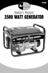
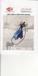
Owner's Manua!
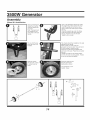
350O
SP-GG350
ton
s_nvlcE
CALL:
888-8964881
PARASERVICIO
LLAME:
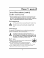
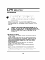
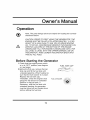
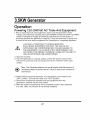
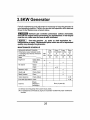
DANGER
Carbon
Using
a generator
Monoxide
indoors WiLL
Carbon
KiLL YOU iN MINUTES.
Monoxide
Generator exhaust contains high levels of carbon monoxide (CO), a poisonous
gas you cannot see or smell. If you can smell the generator exhaust, you are
breathing CO. But even If you cannot smell the exhaust, you could be breathing
CO.
• NEVER use a generator inside homes, garages, crawlspaces, or other partly
enclosed areas. Deadly levels of carbon monoxide can build up in these areas.
Using a fan or opening windows and doors does NOT supply enough fresh air.
• ONLY use a generator outdoors and far away from open windows, doors, and
vents. These openings can pull in generator exhaust.
Even when you use a generator correctly, CO may leak into the home. ALWAYS
use a battery-powered or battery-backup CO alarm in the home.
If you start to feel sick, dizzy, or weak after the generator has been running,
move to fresh air RIGHT AWAY. See a doctor. You could have carbon
monoxide poisoning.
3.5KWGenerator
Table of Contents
Topic
Page
Safety Guidelines - Definitions
3
General Precautions
3
Assembly
12
Specifications
15
Installation
16
Pre-Operation
Check
18
Operation
19
Inspection, Cleaning, and Maintenance
23
Compliance
25
Maintenance Schedule
26
Transporting/Storage
30
Limited Warranty
32
Parts Listing
35
WARNING! READ AND UNDERSTAND ALL SAFETY
PRECAUTIONS IN THIS MANUAL BEFORE OPERATING.
FAILURE TO COMPLY WITH INSTRUCTIONS IN THIS
MANUAL COULD RESULT IN PERSONAL INJURY,
PROPERTY DAMAGE, AND/OR VOIDING OF YOUR
WARRANTY. STEELE® WILL NOT BE
LIABLE FOR ANY DAMAGE BECAUSE OF FAILURE TO
FOLLOW THESE INSTRUCTIONS.
2
Owner'sManual
Safety Guidelines- Definitions
This manual contains important information that you need to know and
understand in order to protect YOUR SAFETY and to PREVENT
EQUIPMENT PROBLEMS. The following symbols help you recognize this
information. Please read the manual and pay attention to these sections.
WARNINGJWARNINGSINDICATEA CERTAINTYOR STRONG
POSSIBILITYOF PERSONALINJURYOR DEATHIF INSTRUCTIONS
ARE NOTFOLLOWED.
CAUTION: CAUTIONS INDICATE A POSSIBILITY OF
EQUIPMENT DAMAGE IF INSTRUCTIONS ARE NOT
FOLLOWED.
®
Note: Notes give helpful information.
WARNINGJIMPROPEROPERATIONOR MAINTENANCEOF THIS
PRODUCTCOULDRESULTIN SERIOUSINJURYAND PROPERTY
DAMAGE.READAND UNDERSTANDALL WARNINGSAND OPERATING
INSTRUCTIONSBEFOREUSINGTHIS EQUIPMENT.
WHENUSINGAIR
TOOLS,BASICSAFETYPRECAUTIONSSHOULDALWAYSBE
FOLLOWEDTO REDUCETHE RISKOF PERSONALINJURY.
SaveThese Important Safety
Instructions!
Read and understand all of these safety instructions. Be
sure to retain them for future use.
General Precautions
WARNINGJFAILURETO FOLLOWTHESEINSTRUCTIONSCAN
RESULTIN SEVEREINJURYOR DEATH.
CAUTION: FAILURE TO FOLLOW THESE INSTRUCTIONS
CAN ALSO RESUL T IN DAMAGE TO THE TOOL AND/OR THE
ITEM YOU ARE WORKING ON.
3
3.5KWGenerator
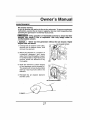
Carbon Monoxide
When this tool is running, ensure that the area is well
ventilated. Never run the engine in an enclosed area. Run the
engine in an open area or with an exhaust evacuation system
in an enclosed area.
WARNING!THE EXHAUSTCONTAINSPOISONOUSCARBON
MONOXIDEGAS THATCAN CAUSELOSS OFCONSCIOUSNESS
AND
MAY LEADTO DEATH.
Gasoline and Oil
This product requires oil and fuel. Attempting to start the
engine without oil will ruin the engine and void the warranty.
Work in well ventilated area. Keep cigarettes, flames or
sparks away from the work area or where gasoline is stored.
WARNING! GASOLINEIS EXTREMELYFLAMMABLEAND IS
EXPLOSIVEUNDERCERTAINCONDITIONS.KEEP OUTOF REACHOF
CHILDREN.
Gasoline fuel and fumes are flammable and potentially explosive. Use
proper fuel storage and handling procedures. Always have multiple ABC
class fire extinguishers nearby.
Keep the generator and surrounding area clean at all times.
Fuel or oil spills must be cleaned up immediately. Dispose of fluids and
cleaning materials as per any local, state, or federal codes and
regulations. Store oily rags in a covered metal container.
•
Never store fuel or other flammable materials near the generator.
•
Do not smoke, or allow sparks, flames or other sources of ignition
around the engine and fuel tank. Fuel vapors are explosive.
Keep grounded conductive objects, such as tools, away from exposed,
live electrical parts and connections to avoid sparking or arcing. These
events could ignite fumes or vapors.
Do not refill the fuel tank while the engine is running or while the engine
is still hot. Do not operate the generator with known leaks in the fuel
system.
Use only engine manufacturer recommended fuel and oil.
4
Owner'sManual
General Precautions (cont'd)
Gasoline and Oil (cont'd)
Excessive buildup of unburned fuel gases in the exhaust system can
create a potentially explosive condition. This buildup can occur after
repeated failed start attempts, valve testing, or hot engine shutdown. If
this occurs, open exhaust system drain plugs, if equipped, and allow the
gases to dissipate before attempting to restart the generator.
Hot Components
WARNING! ENGINEAND EXHAUSTSYSTEMPARTSBECOMEVERY
HOTAND REMAINHOT FORSOMETIMEAFTERTHE ENGINEIS RUN.
WEARINSULATEDGLOVESORWAIT UNTILTHE ENGINEAND
EXHAUSTSYSTEMHAVECOOLEDBEFOREHANDLINGTHESE
PARTS.
Power Output
This generator is not designed to power sensitive electronic equipment
(including computers and medical devices) without the addition of an
approved line conditioner, which is sold separately.
CAUTION: ATTEMPTING TO POWER SENSITIVE
ELECTRONIC EQUIPMENT WITHOUT THE USE OF AN
APPROVED LINE CONDITIONER MAY CAUSE DAMAGE TO
THE EQUIPMENT. ALL-POWER IS NOT RESPONSIBLE FOR
ANY DIRECT OR INDIRECT DAMAGE CAUSED BY FAILURE
TO USE AN APPROVED LINE CONDITIONER.
WorkArea
•
Keep your work area clean and well lit. Cluttered benches
and dark areas invite accidents.
•
Do not operate power tools in explosive atmospheres,
such as in the presence of flammable liquids, gases, or
dust. Generators create sparks which may ignite the dust or fumes.
•
Keep bystanders, children, and visitors away while operating a
generator. Provide barriers or shields as needed.
5
3.5KWGenerator
•
Grounded tools must be plugged into an outlet properly
with all codes and
ordinances, Never remove the grounding prong or modify
the plug in any way, Do not use any adapter plugs,
•
Grounding provides a low-resistance path to carry electricity away from
the user in the event of an electrical malfunction,
•
Double insulated tools are equipped with a polarized plug where one
blade is wider than the other. This plug fits in a polarized outlet only one
way. If the plug does not fit fully in the outlet, reverse the plug. If it still
does not fit, contact a qualified electrician to install a polarized outlet. Do
not change the plug in any way. Double insulation eliminates the need
for the three-wire grounded power cord and grounded power supply
system.
•
Avoid body contact with grounded surfaces such as pipes, radiators,
ranges, and refrigerators. There is an increased risk of electric shock if
your body is grounded.
•
Do not expose generator to rain or wet conditions. Water entering a
generator will increase the risk of electric shock.
•
Do not abuse the power cord. Keep power cords away from heat, oil,
sharp edges, or moving parts. Replace damaged power cords
immediately. Damaged power cords increase the risk of electric shock.
•
When operating a power tool outside, use an outdoor extension cord
marked "W-A" or "W". These extension cords are rated for outdoor use,
and reduce the risk of electric shock.
•
All connections and conduits from the generator to the load must only be
installed by trained and licensed electricians, and in compliance with all
relevant local, state, and federal electrical codes and standards, and
other regulations where applicable.
•
The generator must be earth-grounded for fixed installations in
accordance with all relevant electrical codes and standards before
operation.
•
Do not attempt to connect or disconnect load connections while standing
in water, or on wet or soggy ground.
•
Do not touch electrically energized parts of the generator and
interconnecting cables or conductors with any part of the body, or with
any non-insulated conductive object.
installed and Safety
grounded in accordance
Electrical
6
@
Owner'sManual
General Precautions
(cont'd)
Electrical Safety (cont'd)
Before servicing equipment powered by the generator, disconnect the
equipment from its power input.
Keep all electrical equipment clean and dry. Replace any wiring where
the insulation is cracked, cut abraded or otherwise degraded. Replace
terminals that are worn, discolored, or corroded. Keep terminals clean
and tight.
Insulate all connections and disconnected wires.
Guard against electric shock. Prevent body contact with grounded
surfaces such as pipes, radiators, ranges, and refrigerator enclosures.
Personal Safety
Stay alert. Watch what you are doing, and use common
sense when operating a generator. Do not use generator
while tired or under the influence of drugs, alcohol, or
medication. A moment of inattention while operating
generators may result in serious personal injury.
•
Dress properly. Do not wear loose clothing or jewelry. Contain long hair.
Keep your hair, clothing, and gloves away from moving parts. Loose
clothes, jewelry, or long hair can be caught in moving parts.
•
Avoid accidental starting. Make sure the power switch is in its "OFF"
position, and disconnect the spark plug wire when not in use.
•
Remove adjusting keys or wrenches before turning the generator on. A
wrench or a key that is left attached to a rotating part of the generator
may result in personal injury.
•
Do not overreach. Keep proper footing and balance at all times.
•
Use safety equipment. Always wear eye protection. Wear ANSI
approved safety impact eye goggles. Dust mask, non-skid safety shoes,
hard hat, or hearing protection must be used for appropriate conditions.
•
Do not force the generator. Use the correct generator for your
application. The correct generator will do the job better and safer at the
rate for which it is designed.
•
Do not use the generator if the power switch does not turn it on or off.
Any generator that cannot be controlled with the power switch is
dangerous and must be replaced.
7
3.5KWGenerator
General Precautions(cont'd)
GeneratorUse andCare
•
•
•
•
•
Make sure the power switch is in its "OFF" position and disconnect
the spark plug wire before making any adjustment, changing
accessories, or Storing the generator. Such preventive safety
measures reduce the risk of starting the generator accidentally.
Store idle generators out of reach of children and other untrained
persons. Generators are dangerous in the hands of untrained users.
Maintain generators with care. Do not use damaged generator. Tag
damaged generators "Do not use" until repaired.
Check for misalignment or binding of moving parts, breakage of parts,
and any other condition that may affect the generator's operation. If
damaged, have the generator serviced before using. Many accidents
are caused by poorly maintained generators.
Use only accessories that are recommended by the manufacturer for
your model. Accessories that may be suitable for one generator may
become hazardous when used on another generator.
Servicing
•
•
•
Maintain labels and name plates on the generator and engine. These
carry important information. If unreadable or missing, contact
ALL-POWER AMERICA immediately for a replacement.
Generator service must be performed only qualified repair personnel.
Service or maintenance performed by unqualified personnel could result
in a risk of injury.
When servicing a generator, use only identical replacement parts.
Follow all appropriate instructions in this manual. Use of unauthorized
parts or failure to follow maintenance instructions may create a risk of
electric shock or injury.
HeartPacemakers
WARNING! PEOPLE WITH PACEMAKERS SHOULD CONSULT THEIR
PHYSICIAN(S) BEFORE USING THIS PRODUCT. ELECTROMAGNETIC
FIELDS IN CLOSE PROXIMITY TO A HEART PACEMAKER COULD
CAUSE INTERFERENCE TO OR FAILURE OF THE PACEMAKER.
8
Owner'sManual
General Precautions
(cont'd)
Installation
Ensure installation meets all applicable safety, and local and national
electrical codes. The installation performed by a qualified, licensed
electrician and building contractor.
All electrical work, including the earth-ground connection, should be
completed by a licensed electrician.
All separate fuel storage or generator supply facility must be built or
installed in full compliance with all relevant local, state, and federal
regulations.
It is recommended to use the generator only in well ventilated outdoor
areas. The running gasoline engine will generate carbon monoxide, a
colorless, odorless gas that, if inhaled, can cause serious injury or
death.
If the generator is installed outdoors, it must be weatherproofed and
should be soundproofed. It should not be run outdoors without
protection to the generator and wiring conduit.
The generator is very heavy. Two or more people should assist
when moving or lifting this product without using the wheels. Never don't lift
the Generator using the engine or alternator lifting lugs. Connect lifting
equipment to the frame of the generator.
•
•
•
•
•
Before lifting the generator, ensure the lift rigging and supporting
structure are in good condition, and are rated to lift such a load.
Keep all personnel away from the suspended generator during
relocating.
The supporting floor/ground surface should be level, and strong enough
to safely hold the weight of the generator. If the floor/grounded surface is
not level, strong cross members should be placed under the full length
of the generator frame at its low side.
For trailer installation, the generator should be mounted on the center
point of the trailer, over the wheels. The trailer must be capable of
supporting the weight of the generator and all contents (tools, etc.)
Install sound-and weather-proofing only when it is not raining or snowing
to avoid trapping moisture within the generator's area.
9
3.5KWGenerator
General Precautions (cont'd)
Mechanical
Always make sure the power switch is in its "OFF" position. Disconnect
the spark plug wire, and allow the engine to completely cool before
carrying out maintenance.
Check for damaged parts. Before using the generator, any part that
appears damaged should be carefully checked to determine that it will
operate properly and perform its intended function. Check for alignment
and binding of moving parts, any broken parts or mounting fixtures, and
any other condition that may affect proper operation technician.
The generator is designed with guards for protection from moving parts.
In any case, care must still be taken to protect personnel and equipment
from other mechanical hazards when working around the generator.
Do not operate the generator with safety guards removed. While the
Generator is running, do not attempt to reach around the safety guard
for maintenance or any other reason.
Keep hands, arms, long hair, loose clothing, and jewelry away from
moving parts. Be aware that when engine parts are moving fast they
cannot be seen clearly.
Keep access doors on enclosures closed and locked when access is not
required.
When working on or around the generator always wear protective
clothing including ANSI approved safety gloves, safety eye goggles, and
safety hat.
Do not alter or adjust any part of the generator that is assembled and
supplied by the manufacturer.
Always follow and complete scheduled engine and generator
maintenance.
Chemicals
Avoid contact with hot fuel, oil, exhaust fumes, and hot solid surfaces.
Avoid body contact with fuels, oils, and lubricants used in the generator.
If swallowed, seek medical treatment immediately. Do not induce
vomiting if fuel is swallowed. For skin contact, immediately wash with
soap and water. For eye contact, immediately flush eyes with clean
water and seek medical attention.
10
Owner's Manual
General
Precautions
(cont'd)
Noise
Prolonged exposure to noise levels above 85 dB is hazardous to hearing.
Always wear ANSI approved ear protection when operating or working
around the Generator when it is running.
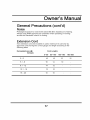
Extension Cord
If an extension cord (not included) is used, make sure to use only UL
approved cords having the correct gauge and length according to the
following table:
NameplateAmps (@
full load)
Cord Lengths
0'-50'
50'-100'
0-5
16
16
5.1 -8
16
14
8.1 - 12
14
12
12.1 - 15
12
10
15-20
10
10
11
100'-150'
150'-200'
12
12
10
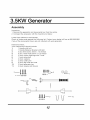
3. KW Gen rator
Assembly
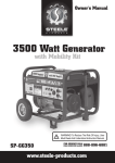
Unpacking
1. Remove the generator and loose parts box from the carton.
2. Compare the accessory with the inventory list below.
Loose Parts (Wheel kit and handle)
Check all loose parts against the following list. Contact your dealer toll free at 888.896.6881
if any of the loose parts shown are not included with your generator
Hardware Check:
Your Hardware Kit should include:
1
1 Handle with bolt
2
1 Handle Retainer Bracket with Bolt
3
4 (six) 8mm bolts, (6mm x 1.0) thread
4
4 (six) 10mm Nuts (6mm x 1.0) thread
5
2 (two) rubber bushings with 2 nuts
6
1 (one) axle shaft
7
2 (two) washers
8
2 (two) cotter pins
9
4 (four)leg bolts and nuts
10)
2 (two) generator leg
11)
2 (two) wheels (not shown)
4_@@@@
I
6
1
I
@@@@
12
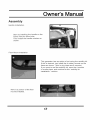
Own r's Manual
Assembly
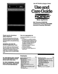
Handle Installation.
Start by installing the handle on the
frame with two 8mm bolts.
Then install the handle retainer as
shown.
Floor Mount Instalation
This generator has an option of not using the mobility kit.
If this is desired, just install the 4 rubber mounts on the
frame as shown. (this is why there are 6 mounts).
If you want to use the mobility kit, save the 4 mounts
in a safe place, and continue to the "mobility kit
installation." section.
Here is a picture of the floor
mounts installed.
I3
Generator
Assembly
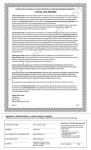
Wheel Kit Installation
Start by installing the
rubber floor mounts
onto the support teg
as shown.
Note: The leg should
be installed on the
same side as the putt
handle.
Here is the hardware required to install
the support leg. Place a block of wood
under the generator so that you don't
have to hold it up while trying to install
the teg.
Place the support leg under the frame.
Push the bolt thru the frame and thru
the leg. Thread a nut onto the bolt.
Tighten with a wrench.
I
This is what the leg
looks like when it is
installed.
The wheels should be installed on the side
opposite to the handle.
Place a block of wood under the
generator so that you don't have to hold it
up while trying to install the axle.
Push the two axle mount brackets onto
each side of the axet. Place the axte under
the unit.
Thread two bolts thru the tubular frame
and thru the axle mounting plates. Thread
a nut onto the bolt and tighten.
Slide
Push the cotter pin thru
the axle and bend it
backwards
as shown
onto
the
the
a washer
wheels
axle.
over
Place
the
wheel
Your generator is now
mobile. Enjoy!
/
14
Owner's Manual
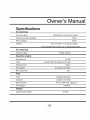
Specifications
AC electrical
Current output
Continuous/rated
120/240VAC @ 25/12.5A, 60Hz
wattage
3,000
Peak wattage
Outlets
3,500
Two 120 VAC, 3- spring grounded
One 120/240 VAC, twist lock, 4- sprin_ _rounded
DC electrical
Current output
Gasoline
12VDC @8.3A
engine
Horsepower
Type
6.5 HP
4-cycle OHV air-cooled recoil start
Displacement
196cc
Oil capacity
0.63 quart (0.6 liter)
EPA approved
yes
Fuel
Type
unleaded gasoline
Capacity
4 gallons (15 liters)
Running time
8 hour/half
Fuel gauge
load (approx.)
included
Weight
Approximate weight
107 Ibs
75-
3.5KW Generator
Installation
Note. Prior to powering tools and equipment, make sure the
generator's rated voltage, wattage, and amperage capacity
(two 120V-25AMPs outlets/one 240V- 12.SAMPs outlet) is adequate
to supply all electrical loads that the unit willpower./fpowering
exceeds the generator's capacity, it may be necessary to group
one or more of the tools and/or equipment for connection to a
separate generator.
Electrical and other permits may be required for the installation of
emergency power systems. Investigate your local building and electrical
codes before installing this unit. Installation must be completed by licensed
contractors.
WARNING! THE GENERA TOR WEIGHS APPROXIMA TEL Y 107
POUNDS. USE CARE AND THE PROPER LIFTING OR HOISTING
EQUIPMENT WHEN MOVING IT TO THE INSTALLA TION LOCATION.
AL WAYS CONNECT HOIST LINES TO THE FRAME OF THE
GENERA TOR.
General Location
Make sure to locate and install the generator outdoors where cooling air
is readily available.
Install the generator so that the air inlets and outlets are not blocked by
obstructions such as bushes, trees, or snow drifts. Locating it in the path
of heavy winds or snowdrifts may require the placement of a barrier for
protection. In normal weather conditions, the air vent should face the
prevailing wind direction.
Install the generator on a concrete slab or other area where rain
drainage or flood waters can not reach it.
Generator placement should allow four feet of access to all sides for
maintenance.
Place the generator as close as possible to the electrical tools and
equipment being powered to reduce the length of extension cords.
If the generator in located indoors the engine exhaust must be ventilated
to the outdoors using leak-proof, heat resistant flexible metal, flex
tubing.
16
Owner's Manual
Installation
(cont'd)
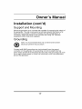
Support and Mounting
Mount the generator on a concrete slab capable of supporting the weight of
the generator. The slab must extend on all sides beyond the flame by at
least one foot. Contact a cement contractor for slab specifications if
necessary. Attach the flame to the concrete slab using 3/8" diameter
expansion anchor bolts (not supplied).
Grounding
electrician perform this procedure.
Note: It is recommended that only a trained and licensed
Connect a #6 AWG grounding wire (not included) from the ground
connector on the generator to a grounding rod (not included) that has
been driven at least 24 inches deep into the earth. The grounding rod must
be an earth-driven copper or brass rod (electrode) which can adequately
ground the generator.
17
3.5KW Generator
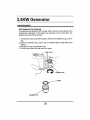
PRE-OPERATION CHECK
Fuel Recommendation
1. Check the fuel level gauge.
2. Refill the tank if the fuel level is low. Do not fill above the shoulder of the
fuel strainer.
,
Gasoline is extremely flammable and is explosive undei"certain
conditions.
- Refuel in a well-ventilated area with the engine stopped. Do not
smoke or allow flames or sparks in the area where the engine is
refueled or where gasoline is stored.
= Do not overfill the fuel tank (there should be no fuelin the fillerneck).
After refueling, make sure the tank cap is closed properly and
securely. Be careful not to spill fuel when refueling. Spilled fuel or
fuel vapor may ignite. If any fuel isspilled, make sure the area is dry
before starting the engine.
, Avoid repeated or prolonged contact with skin or breathing of vapor.
, KEEP OUT OF REACH OF CHILDREN.
Fuel tank capacity: t 5.0
FUEL LEVEL GAUGE
FUEL TANK CAP
Use gasoline with a pump octanerating of 86 or higher
We recommend unleadedgasolinebemuse it producesfewer engine and
sparkplugdepositsand extendsexhaustsystemlife.
Never use stale or contaminatedgasolineor oil!gasolinemixture.Avoid
gettingdirtor water in the fuel tank.
18
Owner's Manual
Operation
Note. The parts//stings
mentioned below.
above are he/pful for/ocating
the contro/s
CAUTION." PRIOR TO FIRST USING THE GENERA TOR, THE
ENGINE MUST BE FILLED WiTH APPROX/MA TEL Y ¾ (0. 63)
QUAR T OFA HiGH QUALITY SAE 10W-30 GRADE ENGINE
OiL. TO DO SO, UNSCREWAND REMOVE THE ENGINE'S OiL
DiPSTiCK LOCA TED A T THE BOTTOM OF THE ENGINE
CRANKCASE FiLL THE ENGINE'S CRANKCASE UNTIL THE
OiL LEVEL iS LEVEL WiTH THE UPPER MARKED LiNE ON
THE DiPSTiCK
THEN, SCREW THE DiPSTiCK BACK iNTO
THE OiL FiLL HOLE
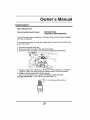
Before Starting the Generator
1 Check that the engine power switch
is in its "OFF" position (see diagram
on next page).
2 Before the first use, remove the fuel
tank cap and fill the fuel tank with
unleaded gasoline. When fueling, be
sure that the fuel strainer is in place.
Replace the fuel tank cap.
Thereafter, check the engine's fuel
gauge for the amount of unleaded
gasoline in the fuel tank. If
necessary, refill the fuel tank with
unleaded gasoline; the generator
must be turned off and cooled down
before refilling the fuel tank.
19
FUEL TANK CAP
FUEL STRAINER
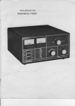
3.5KW Generator
Operation
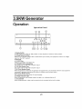
Operation
Panel
©
D
1. Engine
Switch
To start engine turn switch to "ON" position;
2. Voltage
Selector
Switch
To stop engine
Switch to your desired voltage 120V or 240V before
output on the "OFF" position
3. Oil Lamp
4. 12V DC Plug
Used for 12V battery recharging only
5. 125V/250V
30A Locking
Plug
Use under 120V or 240V with full power output
6. 125V 20A Duplex
Plug
Use under 120V or 240V with full power output
7. AC Circle Breaker Reset
turn switch
you connect
to "OFF" position
your equipment.
There
When the generator
overloads,
the generator is equiped with a circuit breaker. Remove
connected
to generator
then press this button to retrieve normal current output.
8. DC Circle Breaker Reset
This function is the same as the AC circuit breaker.
9. Voltage
Indicator
When the generator
10. Ground
Bolt
When
Light
has voltage
using generator,
outputs,
the light is on, otherwise
make sure the ground
wire
20
is connected
light is off.
to the bolt for safety
is no voltage
any equipment
Owner's Manual
Operation (cont'd)
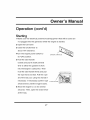
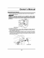
Starting
1 Make sure the electrical
powered tools/equipment
that will be used are
not plugged into the generator while the engine is started.
2 Open the fuel valve
3 Close the choke lever to
about 1/8" clearance.
4Turn the engine power switch to
ENGINE S_
its "ON" position.
5 Hold the start handle
loosely and pull it slowly several
time to allow the gasoline to flow
into the Engine's carburetor.
Then
hold the start handle firmly and pull
the rope hard and fast. Pull the rope
all of the way out, using two hands if
necessaw.
If necessaw
pull the rope
several times until the engine starts.
6 Allow the engine to run for several
seconds. Then, open the choke lever
all the way.
21
STARTER
_RXe
3.5KWGenerator
Operation
Powering
120/240Volt
AC Tools And Equipment:
1 Prior to powering tools and equipment, make sure the generator's rated
voltage, and amperage capacity (two 120V-25AMPs out/ets/one 240V- 12.SAMPs
out/et) is adequate to supply all electrical loads that the unit will power. If
powering exceeds the generator's capacity, it may be necessary to group one
or more of the tools and/or equipment for connection to a separate generator.
CAUTION. ATTEMPTING TO POWER SENSITIVE
ELECTRONIC EQUIPMENT WITHOUT THE USE OF AN
APPROVED LINE CONDITIONER MAY CAUSE DAMAGE TO
THE EQUIPMENT. ALL-POWER IS NOT RESPONSIBLE FOR
ANY DIRECT OR INDIRECT DAMAGE CAUSED BY FAILURE TO
USE AN APPROVED LINE CONDITIONER.
2. Start the machine
3. Once the generator is running, simply connect the power cords of 120/
240 volt AC powered tools and equipment into the 120/240 volt AC dual
outlets.
Note: The Generator features an circuit breaker with the function of
(_
overload protector to protect the AC circuit in case of an overload or
short circuit.
4. When finished using the generator, turn the engine power switch to its
"OFF" position. Turn the fuel valve to its "OFF" position.
5. Disconnect all electrical powered tools and equipment from the
generator's 120/240 volt AC duel outlets.
6. After the engine and generator have completely cooled, store generator
in a safe, clean, dry location (if not already installed).
22
Owner's Manual
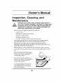
Inspection, Cleaning, and
Maintenance
WARNING!ALWAYSMAKE SURE THE ENGINEPOWERSWITCHIS
IN ITS "OFF" POSITION.DISCONNECTTHE SPARK PLUG WIREFROM
THEENGINE.AND ALLOW SUFFICIENTTIMEFOR THE ENGINEAND
GENERATOR TO COMPLETELY COOL BEFOREPERFORMINGANY
INSPECTIONS,MAINTENANCE,OR CLEANING.
Before each use, inspect the generator. Check for:
Loose screws
Misaligned or binding moving parts
Cracked or broken parts
Damaged electrical wiring
Any other condition that may affect safe operation.
If an engine problem occurs, have it checked by a qualified service
technical before further use. Do not use damaged equipment.
Before each use, make sure the engine's oil and gas levels are
adequate. If necessary, fill the crankcase until the oil level is even with
the oil hill hole and/or fill the fuel tank.
Before each use, remove all debris with a soft brush, rag, or vacuum.
Lubricate all moving parts using a premium quality, lightweight machine
oil.
After first 20 hoursof use, drain the old
engine oil and replace with approximately
3/4(0.63) quart of a high quality SAE
10W-30grade engine oil.
Every 100 hours of use, drain the old
engine oil and replace with approximately
3/4(0.63) quart of a high quality SAE
10W-30 grade engine oil.
For long term storage, either drain fuel
into a suitable container or add a fuel
preservative/stabilizer
(not included)
prevent fuel breakdown.
to
23
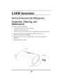
3.5KW Generator
(Befit
for
theGenerators
with
CARBapproved.)
inspection,
Cleaning,
and
Maintenance
•
Spark arrestor maintenance:
1) unscrew screw from the end of muffler.
2) Remove the spark arrestor.
3) Use a wire brush to remove carbon deposits from spark arrestor screen
o
If the generator has been running, the muffler will be very hoL
Allow it to cool before proceeding.
•
The spark arrestor must be serviced every 100 hours to maintain its
efficiency.
4) Reinstall spark arrestor
24
Owner's Manual
Compliance
Manufacturer:JIANGSU
JIANGDONG
GROUP
CO. LTD.
Engine Family:8JDGS.1961GA
Certificate Number:JDG-NRSI-08-04
FELs:
g/kW-hr
HC+NOx:
Effective Date:
1/7/2008
Date Issued:
1/7/2008
N/A
Karl J. Simon, Director
Compliance and Innovative Strategies Division
Office of Transportation and Air Quality
Pursuant to Section 213 of the Clean Air Act (42 U.S.C. section 7547) and 40 CFR
90, and subject to the terms and conditions prescribed in those provisions, this
certificate of conformity is hereby issued for the following small nonroad engine
family, more fully described in the documentation required by 40 CFR 90 and
produced in the stated model year. This certificate of conformity covers only those
new small nonroad engines which conform in all material respects to the design
specifications that applied to those engines described in the documentation required
by 40 CFR Part 90 and which are produced during the model year stated on this
certificate. This certificate of conformity does not cover small nonroad engines
imported prior to the effective date of the certificate.
It is a term of this certificate that the manufacturer shall consent to all inspections
described in 40 CFR 90.126 and 90.506 and authorized in a warrant or court order.
Failure to comply with the requirements of such a warrant or court order may
lead to revocation or suspension of this certificate for reasons specified in 40 CFR
Part 90. It is also a term of this certificate that this certificate may be revoked or
suspended or rendered void ab initio for other reasons specified in 40 CFR Part 90.
This certificate does not cover small nonroad engines sold, offered for sale, or
introduced, or delivered for introduction, into commerce in the U.S. prior to the
effective date of the certificate.
25
3.5KW Generator
Periodic maintenance and adjustment is necessary to keep the generator in
good operating condition, Perform the service and inspection at Me intervals
shown in the Maintenance schedule below.
_haust
gas contains poisonous carbon monoxide.
Shut off the engine before performing any maintenance, if the engine
must be run, make sure the area is well ventilated,
[ NOTICE J
Use only genuine JD parts or their equivalent for
maintenance or repair. Replacement pads which _ not of equ_alent
quality may damage the generator.
;IEGULAR SERVICE PERIOD
_erformed at every indicated month
_roperating hour interval, whichever
.crees first.
First
month
or
20 Hrs.
Bz6h
use
(3)
.:nglne oil
Check level
O
(3)
0
Check
(3)
O
o(1)
}ediment Cup
Clean
o
_park pulg
Check-Clean
o
_park Arrester
Clean
o
ralve clearance
Check*Adjust
o (2)
:uel
tank and strainer Clean
..........................
(Replace if
Check
necessary)
(3)
o
Clean
:uei line
........
Every
year
or
300 Hrs.
,
Change
_ircleaner
Every
Every
3 months 6 months
or
or
50 Hr&
100 Hrs_
"
o (2)
i
Every 2 years (2)
I
(1) Service more frequently when used in dust;,, areas.
(2) For prof_ional
intePTals.
commercial use, log hours of operation to determine proper maintenance
26
Owner's Manual
MAINTENANCE
Air cleaner service
A dirty air cleaner will restrict air flow to the carburetor. To prevent carburetor
malfunction, service the air cleaner regularly. Service more frequently when
operating the generator in extremely dusty areas.
Using gasoline or flammable solvent to clean the filter
element can cause a fire or explosion. Use onlysoapy water or
nonflammable solvent.
[ NOTICE I
Never run the generator
engine wear will result.
1. Unsnap the air cleaner cover clips,
remove the air cleaner cover, and
remove the element.
2. Wash the element in a solution of
household
detergent
and warm
water, then rinse thoroughly, or wash
in nonflammable or high flash point
solvent. Allow the element to dry
thoroughly.
without
the air cleaner. Rapid
AIRCLEANERCOVER
CLIP
3. Soak the element in clean engine
oil and squeeze out the excess oil.
The engine will smoke during initial
start-up ff too much oil is left in the
element.
4. Reinstall the air cleaner
and the cover.
element
AIR CLEANER
27
ELEMENT
3.5KW Generator
MAINTENANCE
Fuel Sediment Cup Cleaning '
The sediment cup prevents dirt or water which may be in the fuel tank from
entering the carburetor. If the engine has not been run for a long time, the
sediment cup should be cleaned.
1. Turn the fuel valve to the OFF position.Remove the sediment cupl and Oring.
2. Clean the sediment cup, and O-ring, in nonflammable or high flash point
solvent.
3. Reinstall O-ring, and sediment cup.
4. Turn the fuel valve ON and check for leaks.
VALVE
SEDIMENT CUP
SEDIMENT CUP
28
Owner's Manual
MAINTENANCE
Spark Plug Service
Recommended
spark plugs:
W20EPR-U
(NIPPONDENSO)
To ensure proper engine operation, the spark plug must be properly gapped
and free of deposits.
If the engine has been running, the muffler will be very hot. Be careful not to
touch the muffler.
1. Remove the spark plug cap,
2. Clean any dirt from around the spark plug base,
3. Use the wrench supplied in the tool kit to remove the spark plug.
PLUG
WRENCH
5. Visually inspect the spark plug, Discard it if the insulator is cracked or
chipped. Clean the spark plug with a wire brush if it is to be reused.
6. Measure the plug gap with a feeler gauge.
Correct as necessary by carefully bending the side electrode.
The gap should be: 0.70-0.80 mm (0.028-O.031 in)
_,_
0.7o--0.80
29
mm (0.028--0.031
in)
3.5KW Generator
TRANSPORTING/STORAGE
When transportingthe generator, turn the engine switch and the fuel valve
OFF. Keep the generator level to prevent fuel spillage, Fuel vapor or spilled
fuel may ignite.
Contact with a hot engine or exhaust system can cause
serious burns or fires. Let the engine cool before transporting or
storing the generator.
Take care not to drop or strike the generator when transporting. Do not place
heavy objects on the generator,
Before storing the unit for an extended period:
1. Be sure the storage area is free of excessive humidity and dust.
2. Service according to the table below:
STORAGE TIME
RECOMMENDED SERVICE PROCEDURE TO
PREVENT HARD STARTING
Less than 1 month
No preparation required
Fill with fresh gasoline and add gasoline
conditioner*.
1 to 2 months
2 months to I year
1 year or more
Fill with fresh gasoline and add gasoline
conditioner*.
Drain the carburetor float bowl
Drain the rue! sediment cup
Fill with fresh gasoline and add gasoline
conditioner*,
DraWnthe carburetor float bowl
Drain the fuel sediment cup
Remove the spark plug. Put a tablespoon of engine
oil into the cylinder. Turn the engine slowly w{ththe
pull rope to distribute the oil. Reinstall the spark
plug.
Change the engine oil
A_r removal from storage, drain the stored gasoline
into a suitable container, and fill w th fresh gasoline
before starting.
30
Owner's Manual
TRANSPORTING/STORAGE
1. Drain the carburetor by loosening the drain screw. Drain the gasoline
into a suitable container.
Gasoline is extremely
flammable
and is explosive
under certain
conditions Perform this task in awell ventilated area with the engine
stopped. Do not smoke or allow flames or sparks in the area during this
DRAIN
SCRE
2. Change the engine oi!
3. Remove the spark plug, and pour about a tablespoon of clean engine oil
into the cylinder. Crank the engine several revolutions to distribute the oil,
then reinstall the spark plug.
4. Slowly pull the starter grip until resistance is felt. At this point, the piston
is coming up on its compression stroke and both the intake and exhaust
valves are closed. Storing the engine in this position will help to protect it
from internal corrosion.
STARTER
31
GRIP
3.5KW Generator
Limited Warranty
STEELE® warrantsto the originalpurchaserwho usesthe productin
a consumerapplication(personal,residentialor householdusage)that all
productscoveredunderthis warrantyare free from defectsin materialand
workmanshipfor one yearfrom the dateof purchase.All productscovered
by this limitedwarrantywhich are usedin commercialapplications(i.e.
incomeproducing)are warrantedto be free of defectsin materialand
workmanshipfor 90 daysfrom the dateof originalpurchase.Products
coveredunderthiswarrantyincludeair compressors,air tools,service
parts,pressurewashers,and generators.
STEELE® will repairor replace,at STEELE®'s sole
option productsor componentswhich havefailedwithin thewarrantyperiod.
Servicewill be scheduledaccordingto the normalwork flow and business
hoursat theservicecenterlocation,andthe availabilityof replacementparts.
All decisionsof STEELE® with regardto this limitedwarrantyshall be final.
Thiswarrantygives youspecificlegal rights,and you may alsohaveother
rightswhichvary from stateto state.
RESPONSIBILITYOF ORIGINALPURCHASER(initialUser):
To processa warrantyclaim on this product,DONOT returnitem to the
retailer.The productmustbe evaluatedby an AuthorizedWarranty
ServiceCenter.Forthe locationof the nearestAuthorizedService
Centercall866-896-6881or visit our website:
@www.steele-products.com
•
Retainoriginalcash registersales receiptas proofof purchasefor
warrantywork.
•
Use reasonablecarein theoperationand maintenanceof the productas
describedin the OwnersManual(s).
•
Deliveror shipthe productto the nearestAuthorizedWarrantyService
Center.Freightcosts,if any, mustbe paidby the purchaser.
•
Air compressorswith 60 and 80 gallontankswill be inspectedat the site
of installation.Contactthe nearestAuthorizedWarrantyServiceCenter
that provideson-siteservicecalls for servicecall arrangements.
•
If the purchaserdoesnot receivesatisfactoryresultsfromthe
AuthorizedWarrantyServiceCenter,the purchasershouldcontact
STEELE®.
32
Owner's Manual
Limited Warranty
(cont'd)
THISWARRANTYDOESNOTCOVER:
•
Merchandisesoldas reconditioned,usedas rentalequipment,or flooror
displaymodels.
•
Merchandisethat has becomedamagedor inoperativebecauseof
ordinarywear,misuse,cold, heat,rain,excessivehumidity,freeze
damage,use of improperchemicals,negligence,accident,failureto
operatethe productin accordancewith the instructionsprovidedin the
OwnersManual(s)suppliedwith the product,impropermaintenance,the
useof accessoriesor attachmentsnot recommendedbySTEELE®,
or unauthorizedrepairor alterations.
•
Repairand transportationcostsof merchandisedeterminednot to be
defective.
•
Costsassociatedwith assembly,requiredoil, adjustmentsor other
installationand start-upcosts.
•
Expendablepartsor accessoriessuppliedwith the productwhich are
expectedto becomeinoperativeor unusableafter a reasonableperiod
of use.
•
Merchandisesold by STEELE® which has beenmanufactured
by and identifiedas the productof anothercompany,such as gasoline
engines.The productmanufacturer'swarranty,if any,will apply.
•
All illustrations,
specifications,
imagesandtechnicalinformation
contained
in thisdocumentarebasedon themostcurrentinformation
availableatthe
timeofdistribution.STEELE® reservestherightto makechangestothis
itemandaccessories
aswellascolors,materials,equipment,specifications,
modelsandanysupportingdocumentation,
atanytimeandwithoutnotice.
33
3.5KW Generator
Limited Warranty
•
•
ANY INCIDENTAL, INDIRECT OR CONSEQUENTIAL LOSS,
DAMAGE, OR EXPENSE THAT MAY RESULT FROM ANY
DEFECTS,
FAILURE OR MALFUNCTION OF THE PRODUCT IS NOT COVERED
BY THISWARRANTY. Some states do not allow the exclusion, so it
maynot apply to you.
IMPLIED WARRANTIES, INCLUDING THOSE OF
MERCHANTABILITY OR FITNESS FOR A PARTICULAR PURPOSE,
ARE LIMITED TO ONE YEAR FROM THE DATE OF ORIGINAL
PURCHASE. Some states do not allow limitations on how long an
implied warranty lasts, so the above limitations may not apply to you.
34
Owner's Manual
PARTS LISTI NG
35
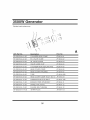
3500W Generator
Cylinder
head system assy.
APA Part No.
Descri
tion
Part. No
SP-GG350-A-01-JD
CYLINDER
HEAD COMP.
JF200-A-01
SP-GG350-A-02-JD
EX. VALVE
GUIDE
JF168-A-02
SP-GG350-A-03-JD
IN. VALVE
GUIDE
JF168-A-03
SP-GG350-A-04-JD
VALVE
SP-GG350-A-05-JD
CYLINDER
SP-GG350-A-06-JD
HEAD COVER
COMP.
JF168-A-06
SP-GG350-A-07-JD
HEAD COVER
PACKING
JF168-A-07
SP-GG350-A-08-JD
TUBE
SP-GG350-A-09-JD
HEAD COVER
COMP.
SP-GG350-A-10-JD
CARBURETOR
STUD
SP-GG350-A-11-JD
EXHAUST
SP-GG350-A-12-JD
DOWEL
SP-GG350-A-13-JD
FLANGE
SP-GG350-A-14-JD
SPARK
GUIDE
CLIP
JF168-A-04
HEAD SEALING
PAD
JF200-A-05
JF168-A-08B
BOLT(Mx12)
JF168-A-09
BOLT
JF168-A-10B
PIPE STUD BOLT
PIN (10X16)
BOLT (MSX58)
PLUG
JF168-A-11
JF168-A-12
JF168-A-12
JF168-A-12
36
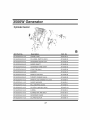
3500W Generator
Cylinder barrel
\o
\
15
APA Part No.
\
\
8
B
17
Descri
tion
Part. No
SP-GG350-B-01-JD
CRANK CASE
JF200-B-01
SP-GG350-B-02-JD
OIL LEVEL SWITCH ASSY.
JF168-B-02
SP-GG350-B-03-JD
GOVERNOR
JF168-B-03
SP-GG350-B-04-JD
SLIDER SHAFT
JF168-B-04
SP-GG350-B-05-JD
GOVERNOR
JF168-B-05
SP-GG350-B-06-JD
LOCK PIN (8ram)
JF168-B-06
SP-GG350-B-07-JD
WASHER
JF168-B-07
SP-GG350-B-08-JD
DRAIN PLUG BOLT
JF168-B-08
SP-GG350-B-09-JD
THRUST WASHER
JF168-B-09
SP_
DRAIN PLUG WASHER
SP-GG350-B-11
-JD
GEAR ASSY.
ARM SHAFT
10.2ram
SLIDER WASHER
JF168-B-10
JF168-B-11
SP-GG350-B-12-JD
BALL BEARING
6205
JF168-B-12
SP-GG350-B-13-JD
OIL SEAL ( q_25xq_41.25x6)
JF168-B-13
SP-GG350-B-14-JD
O-RING
JF168-B-14
SP-GG350-B-15-JD
FLANGE NUT AND BOLT
JF168-B-15
SP-GG350-B-16-JD
GOVERNOR
JF168-B-16
SP-GG350-B-17-JD
OIL PROTECTOR
SLIER
JF168-B-17
37
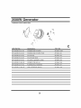
3500W Generator
Crankcase
cover system assy.
1
\
7
4
3
APA Part No.
SP-GG350-C-01
Descri
-JD
C
tion
Part. No
CRANKCASE
COVER
JF168-C-01
SP-GG350-C-02-JD
CRANKCASE
COVER
SP-GG350-C-03-JD
OiL SCALE
SP-GG350-C-04-JD
OiL SCALE
SP-GG350-C-05-JD
OiL SEAL(q)25Xq_41.25X8)
PAD
JF168-C-02
JF168-C-03
SEAL
JF168-C-04
JF168-C-05
SP-GG350-C-06-JD
DOWEL
PiN (8X 14)
JF168-C-06
SP-GG350-C-07-JD
FLANGE
BOLT (M8X28)
JF168-C-07
SP-GG350-C-08-JD
BALL BEARING
(6205)
38
JF168-C-08
B
3500W Generator
Crankshaft
system
assy.
\
1
D
APA Part No.
Descri
tion
SP-GG350-D-OI-JD
CRANKSHAFT
SP-GG350-D-02-JD
SEMICIRCLE
Part. No
COMP.
KEY
JF200-D-01
JF168-D-02
39
3500W Generator
Piston
and connecting
rod system
assy.
5
/
6
10
9
APA Part No.
Descri
tion
Part. No
SP-GG350-E-01-JD
COMPRESSION
RING A
JF200-E-01
SP-GG350-E-02-JD
COMPRESSION
RING B
JF200-E-02
SP-GG350-E-03-JD
OIL RING A
JF200-E-03
SP-GG350-E-04-JD
OIL RING B
JF200-E-04
SP-GG350-E-05-JD
PISTON
JF200-E-05
SP-GG350-E-06-JD
PISTON
SP-GG350-E-07-JD
PISTON
SP-GG350-E-08-JD
CONNECTING
ROD
JF200-E-07
SP-GG350-E-09-JD
CONNECTING
COVER
JF200-E-08
SP-GG350-E-10-JD
CONNECTING
ROD BOLT
JF200-E-09
PIN CLIP
JF200-E-05
PIN
JF200-E-06
40
3500W Generator
Recoil starter system assy.
14
7\
7
APA Part No.
SP-GG350-F-01
Descri
-JD
tion
Part. No
PIVOT ADJUSTING
NUT
JF168-F-01
SP-GG350-F-02-JD
ROCKER
ARM PIVOT
JF168-F-02
SP-GG350-F-03-JD
ROCKER
ARM
JF168-F-03
SP-GG350-F-04-JD
PIVOT
BOLT (MS)
JF168-F-04
SP-GG350-F-05-JD
PUSH ROD GUIDE
SP-GG350-F-06-JD
PUSH ROD
JF168-F-06
SP-GG350-F-07-JD
VALVE
JF168-F-07
SP-GG350-F-08-JD
CAMSHAFT
JF168-F-08
SP-GG350-F-09-JD
VALVE
JF168-F-09
SP-GG350-F-10-JD
EX. VALVE
SP-GG350
-F-11 -JD
VALVE
PLATE
LIFTER
ROTATOR
SPRING
RETAINER
SPRING
JF168-F-05
JF168-F-10
JF168-F-11
SP-GG350-F-12-JD
IN. VALVE
SPRING
RETAINER
SP-GG350-F-13-JD
IN. VALVE
JF168-F-13
SP-GG350-F-14-JD
EX. VALVE
JF168-F-14
41
JF168-F-12
3500W Generator
Recoil starter system assy.
/
5
/
\
6
12
3
7
APA Part No.
Descri
tion
Part. No
SP-GG350-G-01-JD
RECOIL
STARTER
SP-GG350-G-02-JD
SETTING
SCREW
JF168-G-02
SP-GG350-G-03-JD
SPRING
RETAINER
JF168-G-03
SP-GG350-G-04-JD
PLATEN
SPRING
JF168-G-04
SP-GG350-G-05-JD
STARTER
SP-GG350-G-06-JD
RETURN
SPRING
SP-GG350-G-07-JD
RECOIL
STARTER
REEL
JF168-G-07
SP-GG350-G-08-JD
RECOIL
STARTER
SPRING
JF168-G-08
SP-GG350-G-09-JD
RECOIL
STARTER
CASE COMP.
JF168-G-09
SP-GG350-G-10-JD
RECOIL
STARTER
ROPE
JF168-G-10
SP-GG350-G-11-JD
STARTER
SP-GG350-G-12-JD
FLANGE
SP-GG350-G-13-JD
RECOIL
ASSY.
RATCHET
JF168-G-05
JF168-G-06
KNOB
JF168-G-11
BOLT (M6X8)
STARTER
JF168-G-01
SPACER
42
JF168-G-12
JF200-G-13
3500W Generator
Fan cover system assy.
6
2
tion
H
APA Part No.
Descri
Part. No
SP-GG350-H-01-JD
FAN COVER
SP-GG350-H-02-JD
FLYWHEEL
SP-GG350-H-03-JD
SHROUD
SP-GG350-H-04-JD
AIR CLEANER
SP-GG350-H-05-JD
FLANGE
BOLT (M6 X 12)
JF168-H-05
SP-GG350-H-06-JD
FLANGE
BOLT (M6 X 16)
JF168-H-06
COMP.
SIDE PLATE
JF168-H-01
JF168-H-02
JF168-H-03
SUPPORT
43
JF168-H-04
3500W Generator
Carburetor system assy.
1
3
/
4
I
APA Part No.
SP-GG350-1-01
Descri
-JD
tion
Part. No
CARBURETOR
ASSY.
SP-GG350-1-02-JD
CARBURETOR
PAPER
SP-GG350-1-03-JD
CARBURETOR
INSULATING
SP-GG350-1-04-JD
INTAKE
PIPE GASKET
44
JF200-1-01 B
GASKET
PLATE
JF168-1-02
JF200-1-03B
JF168-1-04
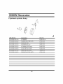
3500W Generator
Flywheel
system Assy.
\
4
\
3
\
tion
j
APA Part No.
Descri
Part. No
SP-GG350-J-01-JD
FLYWHEEL
SP-GG350-J-02-JD
FLANGE
SP-GG350-J-03-JD
COOLING
FAN
JF168-J-03
SP-GG350-J-04-JD
STARTER
PULLEY
JF168-J-04
SP-GG350-J-05-JD
FLYWHEEL
SP-GG350-J-06-JD
STOP SWITCH
SP-GG350-J-07-JD
IGNITION
SP-GG350-J-08-JD
SPARK
JF168-J-01A
BOLT (M6 X 25)
NUT (M16)
JF168-J-02
JF168-J-05
CORD
JF168-J-06
COIL ASSY.
JF168-J-07
PLUG CAP ASSY.
45
JF168-J-08
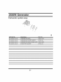
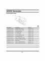
3500W Generator
Control System Assy.
/
M
APA Part No.
SP-GG350-M-01
Descri
-JD
tion
Part. No
CONTROL
ASSY.
SP-GG350-M-02-JD
CONTROL
BASE COMP.
SP-GG350-M-03-JD
CONTROL
ADJUSTING
SP-GG350-M-04-JD
PAN SCREW
SP-GG350-M-05-JD
FLANGE
SP-GG350-M-06-JD
GOVERNOR
SP-GG350-M-07-JD
THROTTLE
RETURN
SP-GG350-M-08-JD
GOVERNOR
ROD
SP-GG350-M-09-JD
FLANGE
SP-GG350-M-10-JD
SP-GG350-M-11
-JD
JF168-M-01B
JF168-M-02B
SPRING
JF168-M-03
M5X34JF168-M-04
BOLT (M6 X 14)
SPRING
JF168-M-05
JF168-M-06
SPRING
JF168-M-07
JF168-M-08
JF168-M-09
NUT (M6)
GOVERNOR
ARM BOLT (M6)
JF168-M-10
GOVERNOR
ARM
JF168-M-11
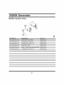
46
3500W Generator
Muffler System Assy.
N
APA Part No.
Descri
tion
SP-GG350-N-01-JD
MUFFLER
SP-GG350-N-02-JD
Part. No
STAY COMP.
JD3000-N-01
FLANGE
BOLT (M8 X 40)
JD3000-N-02
SP-GG350-N-03-JD
FLANGE
BOLT (M6 X 16)
JD3000-N-03
SP-GG350-N-04-JD
MUFFLER
SP-GG350-N-05-JD
MUFF. OUTER
SP-GG350-N-06-JD
FLANGE
COMP.
JD3000-N-04
PROTECTOR
BOLT (M8 X 12)
47
COMP.
JD3000-N-05
JD3000-N-06
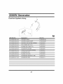
3500W Generator
Air cleaner
\
3
O
APA Part No.
Descri
SP-GG350-O-01-JD
AIR CLEANER
COVER
SP-GG350-O-02-JD
AIR CLEANER
ELEMENT
SP-GG350-O-03-JD
FLANGE
SP-GG350-O-04-JD
AIR CLEANER
SEPARATOR
JD3000-C-04
SP-GG350-O-05-JD
AIR CLEANER
SEAL
JD3000-C-05
SP-GG350-O-06-JD
AIR CLEANER
CASE COMP
JD3000-C-06
SP-GG350
GASKET
-O-07-JD
tion
Part. No
COMP
NUT (M5)
JD3000-C-01
JD3000-C-02
JD3000-C-03
JD3000-C-07
48
3500W Generator
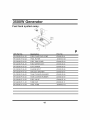
Fuel tank system assy.
4
lo
\
12
APA Part No.
Descri
SP-GG350-P-01-JD
FUEL
P
11
tion
Part. No
FILLER
CAP COMP
JD3000-D-01
SP-GG350-P-02-JD
FUEL FILTER
JD3000-D-02
SP-GG350-P-03-JD
FUEL TANK
JD3000-D-03
SP-GG350-P-04-JD
FUEL
SP-GG350-P-05-JD
FLAT SCREW
JD3000-D-05
SP-GG350-P-06-JD
FLANGE
JD3000-D-06
SP-GG350-P-07-JD
AIR DUCT WASHER
JD3000-D-07
SP-GG350-P-08-JD
TANK CUSHION
WASHER
JD3000-D-08
SP-GG350-P-09-JD
TANK CUSHION
RUBBER
JD3000-D-09
SP-GG350-P-10-JD
SP-GG350-P-11
SP-GG350
-JD
-P-12-JD
COMP.
METER ASSY.
BOLT
JD3000-D-04
FUEL VALVE
JD3000-D-10
TUBE CLIP
JD3000-D-11
FUEL TUBE
JD3000-D-12
49
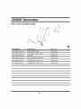
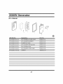
3250W Generator
Control box assy.
11
10
2
3
4
5
6
8
tion
9
Q
APA Part No.
Descri
Part. No
SP-GG350-Q-01-JD
ENGINE
SP-GG350-Q-02-JD
CONTROL
PANEL
SP-GG350-Q-03-JD
VOLTAGE
SWITCH
JD3000-1-Q-03
SP-GG350-Q-04-JD
OIL ALERT
LAMP
JD3000-1-Q-04
SP-GG350-Q-05-JD
DC 12V OUTPUT
JD3000-1-Q-05
SP-GG350-Q-06-JD
120V/240V
JD3000-1 -Q-06
SP-GG350-Q-07-JD
120V RECEPTACLE
SP-GG350-Q-08-JD
EARTH TERMINAL
SCREW
JD3000-1-Q-08
SP-GG350-Q-09-JD
CONTROL
BACK BOX
JD3000-1-Q-09
SP-G G350 -Q-10-JD
INDICATOR
J D3000-1 -Q-10
SP-GG350-Q-11-JD
CIRCUIT
PROTECTOR(10A)
JD3000-1-Q-11
SP-GG350-Q-12-JD
CIRCUIT
PROTECTOR(13A)
JD3000-1-Q-12
SWITCH
ASSY.
COMP.
RECEPTACLE
PANEL
JD3000-1-Q-01
JD3000-1-Q-02
JD3000-1 -Q-07
50
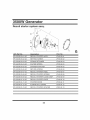
3500W Generator
Frame Comp assy.
8_
MOUNTING
R
2
SP-GG350-R-01-JD
FUEL TANK
BOLT
JD3000-R-01
SP-GG350-R-02-JD
FRAME
COMP.
SP-GG350-R-03-JD
FLANGE
BOLT
JD3000-R-03
SP-GG350-R-04-JD
FLANGE
NUT ML._
JD3000-R-04
SP-GG350-R-05-JD
MOTOR
MOUNT
JD3000-R-05
SP-GG350-R-06-JD
FLANGE
NUT (M8)
JD3000-R-06
SP-GG350-R-07-JD
FLANGE
NUT (M10)
JD3000-R-07
SP-GG350-R-08-JD
RUBBER
FOOT
JD3000-R-08
JD3000-1
(LEFT)
51
-R-02
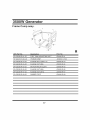
3500W Generator
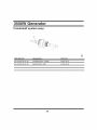
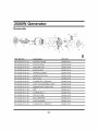
Generator
7
19 11
8
4
3
13
\
\2
12
12
\
3
\
9
10
S
APA Part No.
SP-GG350-S-01
Descri
-JD
tion
Part. No
STATOR
COVER
JD3000-S-01
SP-GG350-S-02-JD
STATOR
ASSY.
JD3000-S-02
SP-GG350-S-03-JD
COOLING
FAN
JD3000-S-03
SP-GG350-S-04-JD
BRUSH
SP-GG350-S-05-JD
TAPPING
SP-GG350-S-06-JD
GENERATOR
SP-GG350-S-07-JD
NUT _
SP-GG350-S-08-JD
FLANGE
SP-GG350-S-09-JD
AUTO VOLTAGE
SP-GG350-S-10-JD
GENERATOR
SP-GG350-S-11
NUT
-JD
ASSY.
JD3000-S-04
SCREW
JD3000-S-05
STAY
JD3000-S-06
JD3000-S-07
BOLT (M6X155)
REG. ASSY.
COVER
(M5_
JD3000-S-08
JD3000-S-09
JD3000-S-10
JD3000-S-11
SP-GG350-S-12-JD
FLANGE
BOLT
JD3000-S-12
SP-GG350-S-13-JD
ROTOR
COMP.
JD3000-S-03
SP-GG350-S-14-JD
BALL BEARING
JD3000-S-14
SP-GG350-S-15-JD
PLAIN WASHER
JD3000-S-15
SP-GG350-S-16-JD
FLANGE
JD3000-S-16
BOLT (M8X227)
52
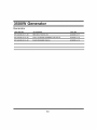
3500W Generator
Generator
APA Part No.
De scri
tion
SP-GG350-S-17-JD
HEX.BOLT
SP-GG350-S-18-JD
VOLT CHANGE
SP-GG350-S-19-JD
PLAIN WASHER
Part. No
(M5 X 20)
TERMINAL
JD3000-S-17
BR-AC-W
JD3000-S-18
JD3000-S-19
_
53
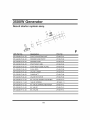
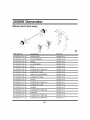
3500W Generator
Wheel
arid
hand
assy.
/12 _
/12
/19
\
3
6
)/12
6
7
16
,Z
12 _8
1
3
9 _
11
1
T
APA Part No.
Descri
SP-GG350-T-01-JD
COTTER
SP-GG350-T-02-JD
PLAIN WASHER
JD3500-T-02
SP-GG350-T-03-JD
WHEEL
JD3500-T-03
SP-GG350-T-04-JD
AXLE
SP-GG350-T-05-JD
AXLE
SP-GG350-T-06-JD
FLANGE
BOLT_
JD3500-T-06
SP-GG350-T-07-JD
FLANGE
NUT
JD3500-T-07
SP-GG350-T-08-JD
VIBRATION
SP-GG350-T-09-JD
FLANGE
SP-GG350-T-10-JD
STAND
S P-GG350-T-
FLANGE
BOLT_
JD3500-T-11
SP-GG350-T-12-JD
FLANGE
NUT (M8)
JD3500-T-12
SP-GG350-T-13-JD
HANDLE
SP-GG350-T-14-JD
FLANGE
S P-GG350-T-
BRACKET
11 -JD
15-JD
tion
Part. No
PIN
JD3500-T-01
HOLDER
JD3500-T-04
JD3500-T-05
ABSORBER
JD3500-T-08
JD3500-T-09
NUT (M8)
JD3500-T-10
JD3500-T-13
BOLT (M6X 60)
JD3500-T-14
J D3500-T-15
SP-GG350-T-16-JD
FLANGE
BOLT (M8X 58)
JD3500-T-16
SP-GG350-T-17-JD
FLANGE
BOLT (M8X 40)
JD3500-T-17
54
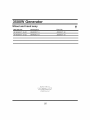
3500W Generator
T
Wheel and hand assy.
APA Part No.
Descri
tion
Part. No
SP-GG350-T-18-JD
BRACKET
A
JD3500-T-18
SP-GG350-T-19-JD
BRACKET
B
JD3500-T-19
16273 E. Gale Ave.
City Of Industw, CA 91745
www.steele-products.com
all rights reserved
55