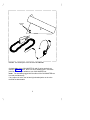
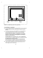
1
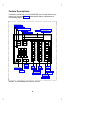
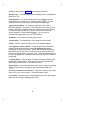
DEFINITY® CALLMASTER® II and CALLMASTER® III Voice Terminals User and Installation Instructions AT&T 555-015-168 COMCODE 107319659 Issue 1, August 1994 bc cb WARRANTY All terms and conditions specified in your agreement with AT&T apply. NOTICE While reasonable efforts were made to ensure that the information in this document was complete and accurate at the time of printing, AT&T can assume no responsibility for any errors. Changes or corrections to the information contained in this document may be incorporated into future issues. TO ORDER COPIES OF THIS DOCUMENT Contact: AT&T Customer Information Center 2855 North Franklin Road P.O. Box 19901 Indianapolis, Indiana 46219 1-800-432-6600, In Canada: 1 800-255-1242 Order: Document No. 555-015-168 Issue 1, August 1994 For more information about AT&T documents, see Business Communications Systems Publications Catalog (555-000-010). Prepared by AT&T GBCS Documentation Development Middletown, New Jersey 07748 1994 AT&T All Rights Reserved Printed in USA 1 fc cf bc cb HEARING AID COMPATIBILITY This terminal is compatible with inductively coupled hearing aids as prescribed by the Federal Communications Commission. INTERFERENCE WARNING INFORMATION - Part 15 of FCC Rules Federal Communications Commission (FCC) Rules require that you be notified of the following: This equipment has been tested and found to comply with the limits for a Class A digital device, pursuant to Part 15 of the FCC Rules. These limits are designed to provide reasonable protection against harmful interference in a business installation. This equipment generates, uses, and can radiate radio frequency energy and, if not installed and used in accordance with the instructions, may cause harmful interference to radio communications. However, there is no guarantee that interference will not occur in a particular installation. If this equipment does cause interference to radio or television reception, which can be determined by turning the equipment off and on, the user is encouraged to try to correct the interference by one or more of the following measures: 1 Reorient or relocate the receiving antenna. 2 Increase the separation between the equipment and receiver. 3 Connect the equipment into an outlet on a circuit different from that to which the receiver is connected. 4 Consult the dealer or an experienced radio/TV technician for help. You may find the following booklet, prepared by the Federal Communications Commission, helpful: How to Identify and Resolve Radio-TV Interference Problems. This booklet is available from the U.S. Government Printing Office, Washington, D.C. 20042, Stock No. 004-000-00345-4. 2 fc cf bc cb IMPORTANT SAFETY INSTRUCTIONS Only the most careful attention has been devoted to quality standards in the manufacture of your new voice terminal. Safety is a major factor in the design of every set. But, safety is YOUR responsibility too. Please carefully read the helpful tips listed below and on the next page. These suggestions will enable you to take the fullest advantage of your new voice terminal. Retain these tips for later use. Use When using your voice terminal, the following safety precautions should always be followed to reduce the risk of fire, electric shock, and injury to persons. d Read and understand all instructions. d Follow all warnings and instructions marked on the voice terminal. d This voice terminal can be hazardous if immersed in water. If you accidentally drop the voice terminal into water, do not retrieve it until you have first unplugged the line cord from the modular wall jack. Do not reconnect the voice terminal until it has dried thoroughly. d Avoid using the voice terminal during electrical storms in your immediate area. There is a remote risk of electric shock from lightning. Urgent calls should be brief. Even though protective measures may have been installed to limit electrical surges from entering your business, absolute protection from lightning is impossible. d If you suspect a natural gas leak, report it immediately, but use a telephone away from the area in question. The telephone’s electrical contacts could generate a tiny spark. While unlikely, it is possible that this spark could ignite heavy concentrations of gas. d Never push objects of any kind into the voice terminal through housing slots since they may touch hazardous voltage points or short out parts that could result in a risk of electric shock. Never spill liquid of any kind on the voice terminal. If liquid is spilled, however, refer servicing to proper service personnel. d To reduce the risk of electric shock, do not disassemble this voice terminal. There are no user-serviceable parts inside. Opening or removing covers may expose you to hazardous voltages. Incorrect reassembly can cause electric shock when the voice terminal is subsequently used. If your voice terminal does not work properly, contact a qualified AT&T service technician. 3 fc cf bc cb Service 1 Before cleaning, unplug the voice terminal from the modular wall jack. Do not use liquid cleaners or aerosol cleaners. Use a damp cloth for cleaning. 2 Unplug the voice terminal from the modular wall jack and refer servicing to qualified service personnel when these conditions exist: d If liquid has been spilled into the voice terminal d If the voice terminal has been exposed to rain or water d If the voice terminal does not operate normally by following the operating instructions, adjust only those controls described in these instructions. Do not attempt to adjust any other controls since doing so may result in damage to the voice terminal and will require extensive work by a qualified technician to restore the voice terminal to normal operation. d If the voice terminal has been dropped or the housing has been damaged d If you note a distinct change in the performance of the voice terminal WARNING: When this product is located in a separate building from the telephone communications system, a line current protector MUST be installed at the entry/exit points of ALL buildings through which the line passes. The following are the ONLY acceptable devices for use in this application: d AT&T 4-type protectors d ITW LINX LP-type protectors CAUTION: This voice terminal is NOT for residential use. It is for business systems applications ONLY. Use in a residential environment could result in an electrical short circuit when the telephone wiring is set up to provide other applications, for example, for appliance control or power transformers. The AC power used in these applications may create a safety hazard by placing a direct short circuit across the telephone wiring. SAVE THESE INSTRUCTIONS When you see this warning symbol on the product, refer to the instructions booklet packed with the product for information before proceeding. 4 fc cf bc cb Contents Your CALLMASTER Voice Terminal ……………………………6 The Headset (or the Handset) ……………………………………6 The Recorder Interface ……………………………………………7 Organization of This Guide…………………………………………7 Conventions …………………………………………………………8 Feature Descriptions ………………………………………………9 Installation……………………………………………………………13 Checklist of Parts …………………………………………………13 Orderable Equipment ……………………………………………14 Installing the CALLMASTER Voice Terminals …………………15 Testing the Headset or Handset …………………………………20 Labeling and Installing the Button-Designation Strips…………20 Feature Procedures ………………………………………………22 Going Off-Hook ……………………………………………………22 Raising or Lowering Receive Volume …………………………22 Disconnecting From Calls ………………………………………23 Conference…………………………………………………………24 Drop…………………………………………………………………25 Hold …………………………………………………………………25 Mute ………………………………………………………………26 Select Ring (and Ringer Volume) ………………………………26 Self-Test ……………………………………………………………27 Transfer ……………………………………………………………28 Technical Description ……………………………………………29 fc cf bc cb Your CALLMASTER Voice Terminal The AT&T CALLMASTER voice terminals referred to in this manual include the CALLMASTER II and the CALLMASTER III models. Both of these voice terminals have been specially designed for use with the Automatic Call Distribution (ACD) system and the many features of DEFINITY Generic 1, Generic 2, and Generic 3. The CALLMASTER II and the CALLMASTER III are identical in appearance. Each has six buttons that can be used for either call appearances or features and 15 buttons that are administered exclusively for features. They also have a 2-line supertwist liquid crystal display for showing call-related information, and designated buttons for both the ACD Log In and Release features. The CALLMASTER II has a built-in Recorder Interface which allows you to connect the voice terminal to a recording device so that you can record all voice interactions. The CALLMASTER III does NOT have a Recorder Interface. For easy identification of which model you are using, see the model number printed on a sticker on the bottom of each CALLMASTER voice terminal. NOTE: The tape recorder used with CALLMASTER II voice terminal with Recorder Interface must be purchased by the user; it is not provided with the voice terminal. For more information on using ACD features, see DEFINITY Generic 1 and Generic 3 ACD Agent Instructions , 555-204-722; DEFINITY Generic 2 and System 85 ACD Agent Instructions, 555-104-713; DEFINITY Generic 1 and Generic 3 ACD Supervisor Instructions , 555-230-724; and DEFINITY Generic 2 and System 85 ACD Supervisor Instructions, 555-104-714. THE HEADSET (OR THE HANDSET) Since the CALLMASTER voice terminal is most often used with a headset, each set has two headset jacks, one on each side of the housing, so that one or two headsets can easily be connected. The voice terminal is immediately off-hook when the headset is plugged into the voice terminal. With the use of an optional handset D-Kit, a K-2G2 optional handset can be added to the voice terminal. (See ‘‘Orderable Equipment’’ in the Installation section of these instructions for Comcodes of the handset D-Kits and individual parts.) This kit includes a handset and handset cord, a PJ327 adapter so that the handset cord can be connected to one of the headset jacks, and a cradle in which the handset can be kept when it is not in use. (This cradle cannot be used as a switchhook). 1 fc cf bc cb If you have both a handset and a headset plugged into a CALLMASTER voice terminal, you may want to unplug the handset when you are not using it, since it can pick up nearby noises (such as papers being shuffled) which may be heard over the headset. THE RECORDER INTERFACE The CALLMASTER II with Recorder Interface is designed for recording calls on a standard analog tape recorder. [A recorder with AGC (Automatic Gain Control) is recommended.] With this interface, a warning tone, a soft beep repeated every 15 seconds, notifies the agent and the calling party that the call is being recorded. Be aware that this tone may be a legal requirement. To generate this warning tone while using the Service Observing feature to monitor calls, the ACD split supervisor must activate the listen/talk mode and remain in this mode while the call is being recorded. Important: The use of service observing features and call recording features may be subject to federal, state, and local laws, rules, or regulations and may be prohibited pursuant to the laws, rules, or regulations or require the consent of one or both of the parties to the conversation. Customers should familiarize themselves with and comply with all applicable laws, rules, and regulations before using these features. ORGANIZATION OF THIS GUIDE This user’s guide is divided into four main sections: Feature Descriptions—Use the drawing to locate the features on your CALLMASTER voice terminal; use the feature descriptions and explanations to help you remember how these features are used. Installation–Use the procedures listed in this section to install your CALLMASTER voice terminal. The procedures are the same for both the CALLMASTER II and CALLMASTER III. Feature Procedures—Follow the procedures listed here to use the fixed features on your voice terminal, those features you can use immediately. Technical Description—This short section contains the dimensions, power requirements, and environmental requirements for the CALLMASTER voice terminal. 2 fc cf bc cb CONVENTIONS The following conventions are used in the procedures: bbbbbbb xxxxx cbbbbbbbc b bbbbbb cbFeature bbbbbbc This box represents a call appearance button, which is used exclusively for placing or receiving calls. The button has a red appearance light and a green status light and is labeled with an extension number (shown as xxxxx). Each of these boxes represents a button to which a feature has been assigned. The button is labeled with a feature name. 3 fc cf bc cb Feature Descriptions Familiarize yourself with your CALLMASTER voice terminal and its many features by reviewing Figure 1 below and the feature explanations on the following pages. b bbbbbbbbbbbbbbbbbbbbbbbbbbbbbbbbbbbbbbbbb c c Message Light c c Drop/Test Button c c Conference/Ring Button 6 Call Appearance/ Hold Button Display c c Feature Buttons Transfer Button c c c c c c c c c c c c c c c c c c c c * c c c c CALLMASTER c c c Volume c Control Mute Release Log In c Button c Button Button Button Select Button c c Adjunct Jack Dial Pad 15 Feature (on bottom of c c Buttons voice terminal) c c Line Jack (on bottom of c c voice terminal) c bbbbbbbbbbbbbbbbbbbbbbbbbbbbbbbbbbbbbbbbbc b Conference Ring Transfer Drop Hold Test Message 1 ABC 2 DEF 3 GHI 4 JKL 5 MNO 6 PQRS 7 TUV 8 WXYZ 9 Oper O # Select Volume Mute Log In Release FIGURE 1 The CALLMASTER (II and III) Voice Terminal 4 fc cf bc cb Starting at the top left of Figure 1 and continuing clockwise: A red light which goes on steadily when a message has been left for you. Message Light Drop/Test Button For disconnecting from a call or dropping b bbbbb the last party added to a conference call. When used with cbSelect bbbbbc , you can perform a self-test of your voice terminal lights and tone ringer. For setting up conference calls. With a DEFINITY Generic 1 or Generic 3, the conference can include up to six parties. DEFINITY Generic 2 users can conference up to three parties. (To add more parties, DEFINITY Generic 2 users should see their b bbbbb system manager.) When used with cbSelect bbbbbc , you can select a personalized ringing pattern for your voice terminal. Conference/Ring Button Hold Button A red button for putting calls on hold. Transfer Button For transferring a call to another voice terminal. Display A built-in supertwist LCD 2-line by 40-character display. 6 Call Appearance/Feature Buttons These six buttons are devoted to handling incoming and outgoing calls (call appearances) and are labeled with an extension number. Each button has a red appearance light beside it to tell you that this is the line you are using or that this is the line you will get when you answer a call. The green status light next to each call appearance and feature button tells you the line or feature is being used. 15 Feature Buttons Each of these 15 buttons accesses a feature and is labeled with a feature name. Each button has a green light beside it. When the green light goes on, the feature is active. Release bbbbbbbb Button Use in ACD operation to end a call. However, pressing Release is equivalent to hanging up; you will not receive dial tone. cbbbbbbbbc Line Jack (on bottom of voice terminal) This jack is used for connecting a line cord to your voice terminal. The jack is labeled ‘‘LINE.’’ Use this button to automatically log in to the ACD system when you want to begin answering ACD calls. Log in Button 5 fc cf bc cb Adjunct Jack (on bottom of voice terminal) This jack is used to connect compatible adjunct equipment, such as an S101A or S201A Speakerphone, a 507A Adapter, or a 500A Headset Adapter, to your voice terminal. The jack is labeled . For turning off the voice transmitter in the headset or handset so the other person cannot hear you. Mute Button For adjusting the volume of the headset (or handset) when you are using the headset (or the handset) and a call is in progress, or for adjusting the volume of the tone ringer when you are not using the headset (or handset), and any time the voice terminal is ringing. You can also use the volume control to change ringer volume while you are selecting a personalized ring. Volume Control Button Dial Pad The standard 12-button pad for dialing phone numbers and accessing features. The letters, ‘‘Q’’ and ‘‘Z,’’ have been added to the appropriate dial pad keys for directory access, and the ‘‘5’’ button on your dial pad has raised bars for visually-impaired users. Select Button Can be used in two different ways: b bbbbb 1) Used with ccbDrop Test c to initiate a self-test of your voice terminal; bbbbbc bbbbbbbbb Conference c to select your own personalized ring from 2) Used with ccbbbbbbbbbc Ring among eight available patterns. 6 fc cf bc cb b bbbbbbbbbbbbbbbbbbbbbbbbbbbbbbbbbbbbbbbbb c c c c c c c c c c Headset c Jacks c c c c c c c c c c c c c c c c c c c c c c c c c c c c c c bbbbbbbbbbbbbbbbbbbbbbbbbbbbbbbbbbbbbbbbbc b FIGURE 2 The headset jacks on the side of the CALLMASTER On both sides of the CALLMASTER (II and III) voice terminals, as shown in Figure 2 above, there is a set of headset jacks. Use these jacks for connecting a headset to your CALLMASTER set. NOTE: Two headsets plugged into the sides of the CALLMASTER can be used simultaneously. If any adjunct is active, the left and right headset jacks on the voice terminal are deactivated. 7 fc cf bc cb Installation Use the following procedures to install your CALLMASTER voice terminal. b bbbbbbbbbbbbbbbbbbbbbbbbbbbbbbbbbbbbbbbbbbbbbbbbbbbbbbbbbbbbbbbbbb c IMPORTANT: ‘‘DEFINITY CALLMASTER II and CALLMASTER III c c Instructions for Programming the Options,’’ 555-015-169, is a brief set c c of instructions which includes procedures for setting the display for c c 1 or 2 lines and for controlling the Mute button. For the c c CALLMASTER II, there are procedures for enabling or disabling the c c Recorder Interface, and the Recording Warning Tones. For the c c c CALLMASTER III, there are procedures for setting the headset volume. c c c It is important that ONLY a service technician or the system manager c c program these options. This document is orderable from the c center listed at the front of this book. cbdocumentation bbbbbbbbbbbbbbbbbbbbbbbbbbbbbbbbbbbbbbbbbbbbbbbbbbbbbbbbbbbbbbbbbb c CHECKLIST OF PARTS The CALLMASTER II and CALLMASTER III voice terminal package includes the following items: d Either a CALLMASTER II Voice Terminal with Recorder Interface or a CALLMASTER III Voice Terminal without Recorder Interface (Both of these CALLMASTER voice terminal models come in black, misty cream, or white.) d Line Cord (7-foot, 8-wire D8W87 modular cord) d Button Designation Strips (silver strips to be used with the black CALLMASTER; international gray strips to be used with the misty cream and the white CALLMASTER) 8 fc cf bc cb ORDERABLE EQUIPMENT The following equipment can be ordered by using the appropriate Comcode: bbbbbbbbbbbbbbbbbbbbbbbbbbbbbbbbbbbbbbbbbbbbbbbbbbbbbbbbbbbbbbbbbbbbbbbbbbbbbbbbbbbb c c Orderable Equipment c c bbbbbbbbbbbbbbbbbbbbbbbbbbbbbbbbbbbbbbbbbbbbbbbbbbbbbbbbbbbbbbbbbbbbbbbbbbbbbbbbbbbb c c c c ITEM c COMCODE c bbbbbbbbbbbbbbbbbbbbbbbbbbbbbbbbbbbbbbbbbbbbbbbbbbbbbbbbbbbbbbbbbbbbbbbbbbbbbbbbbbbb c c c c CALLMASTER II Voice Terminal (with Recorder Interface) c c c c c Black 106693294 c c c Misty Cream 106693302 c c c c c White 107316960 c c c c c CALLMASTER III Voice Terminal (without Recorder Interface) c c c c Black 107316978 c c c c Misty Cream 107316994 c c c c White 107316986 c c bbbbbbbbbbbbbbbbbbbbbbbbbbbbbbbbbbbbbbbbbbbbbbbbbbbbbbbbbbbbbbbbbbbbbbbbbbbbbbbbbbbb c c c c Line Cord (7-foot, 8-wire D8W87 modular cord) c c 103786786 c c c c Line Cord (14-foot D8W modular cord) c 103786802 c bbbbbbbbbbbbbbbbbbbbbbbbbbbbbbbbbbbbbbbbbbbbbbbbbbbbbbbbbbbbbbbbbbbbbbbbbbbbbbbbbbbb c c c c c c Button Designation Strips, package of 25 (silver) 846753099 c c c Button Designation Strips, package of 25 (international gray) 846953115 c c c c Button Designation Strips, package of 200 (silver) c 846953107 c c c c Button Designation Strips, package of 200 (international gray) 846953123 c c bbbbbbbbbbbbbbbbbbbbbbbbbbbbbbbbbbbbbbbbbbbbbbbbbbbbbbbbbbbbbbbbbbbbbbbbbbbbbbbbbbbb c c c c Handset D-Kit #182083 (black) 105514798 cbbbbbbbbbbbbbbbbbbbbbbbbbbbbbbbbbbbbbbbbbbbbbbbbbbbbbbbbbbbbbbbbbbbbbbbbbbbbbbbbbbbb c c c c c 845952944 Handset cradle * cbbbbbbbbbbbbbbbbbbbbbbbbbbbbbbbbbbbbbbbbbbbbbbbbbbbbbbbbbbbbbbbbbbbbbbbbbbbbbbbbbbbb c c c Thumbscrew * c c 845952928 cbbbbbbbbbbbbbbbbbbbbbbbbbbbbbbbbbbbbbbbbbbbbbbbbbbbbbbbbbbbbbbbbbbbbbbbbbbbbbbbbbbbb c c c Handset K2G2 * c 104030762 c bbbbbbbbbbbbbbbbbbbbbbbbbbbbbbbbbbbbbbbbbbbbbbbbbbbbbbbbbbbbbbbbbbbbbbbbbbbbbbbbbbbb c c c c Handset cord H4DU * c 102803327 c bbbbbbbbbbbbbbbbbbbbbbbbbbbbbbbbbbbbbbbbbbbbbbbbbbbbbbbbbbbbbbbbbbbbbbbbbbbbbbbbbbbb c c c PJ327 Adapter * 405730920 cbbbbbbbbbbbbbbbbbbbbbbbbbbbbbbbbbbbbbbbbbbbbbbbbbbbbbbbbbbbbbbbbbbbbbbbbbbbbbbbbbbbb c c bbbbbbbbbbbbbbbbbbbbbbbbbbbbbbbbbbbbbbbbbbbbbbbbbbbbbbbbbbbbbbbbbbbbbbbbbbbbbbbbbbbb c c c Handset D-Kit #182084 (misty cream) 105514806 cbbbbbbbbbbbbbbbbbbbbbbbbbbbbbbbbbbbbbbbbbbbbbbbbbbbbbbbbbbbbbbbbbbbbbbbbbbbbbbbbbbbb c c c c c Handset cradle * 845952951 cbbbbbbbbbbbbbbbbbbbbbbbbbbbbbbbbbbbbbbbbbbbbbbbbbbbbbbbbbbbbbbbbbbbbbbbbbbbbbbbbbbbb c c c c c Thumbscrew * 845952936 cbbbbbbbbbbbbbbbbbbbbbbbbbbbbbbbbbbbbbbbbbbbbbbbbbbbbbbbbbbbbbbbbbbbbbbbbbbbbbbbbbbbb c c c Handset K2G2 * c 105489686 c cbbbbbbbbbbbbbbbbbbbbbbbbbbbbbbbbbbbbbbbbbbbbbbbbbbbbbbbbbbbbbbbbbbbbbbbbbbbbbbbbbbbb c c c Handset cord H4DU * c 104211305 c bbbbbbbbbbbbbbbbbbbbbbbbbbbbbbbbbbbbbbbbbbbbbbbbbbbbbbbbbbbbbbbbbbbbbbbbbbbbbbbbbbbb c c c c PJ327 Adapter * c 405730946 c bbbbbbbbbbbbbbbbbbbbbbbbbbbbbbbbbbbbbbbbbbbbbbbbbbbbbbbbbbbbbbbbbbbbbbbbbbbbbbbbbbbb c c * This piece of equipment comes with the Handset D-Kit, but it can also be ordered separately with the Comcode in the second column. 9 fc cf bc cb bbbbbbbbbbbbbbbbbbbbbbbbbbbbbbbbbbbbbbbbbbbbbbbbbbbbbbbbbbbbbbbbbbbbbbbbbbbbbbbbbbb c c Orderable Equipment (continued) c cbbbbbbbbbbbbbbbbbbbbbbbbbbbbbbbbbbbbbbbbbbbbbbbbbbbbbbbbbbbbbbbbbbbbbbbbbbbbbbbbbbb c c c c c ITEM COMCODE c bbbbbbbbbbbbbbbbbbbbbbbbbbbbbbbbbbbbbbbbbbbbbbbbbbbbbbbbbbbbbbbbbbbbbbbbbbbbbbbbbbb c cbbbbbbbbbbbbbbbbbbbbbbbbbbbbbbbbbbbbbbbbbbbbbbbbbbbbbbbbbbbbbbbbbbbbbbbbbbbbbbbbbbb c c c Handset D-Kit #182835 (white) 107318438 c bbbbbbbbbbbbbbbbbbbbbbbbbbbbbbbbbbbbbbbbbbbbbbbbbbbbbbbbbbbbbbbbbbbbbbbbbbbbbbbbbbb c c c c c Handset cradle * 847278603 c bbbbbbbbbbbbbbbbbbbbbbbbbbbbbbbbbbbbbbbbbbbbbbbbbbbbbbbbbbbbbbbbbbbbbbbbbbbbbbbbbbb c c c 847278611 Thumbscrew * c cbbbbbbbbbbbbbbbbbbbbbbbbbbbbbbbbbbbbbbbbbbbbbbbbbbbbbbbbbbbbbbbbbbbbbbbbbbbbbbbbbbb c c c c Handset K2G2 * 107244352 c cbbbbbbbbbbbbbbbbbbbbbbbbbbbbbbbbbbbbbbbbbbbbbbbbbbbbbbbbbbbbbbbbbbbbbbbbbbbbbbbbbbb c c c c Handset cord H4DU * 105635429 c cbbbbbbbbbbbbbbbbbbbbbbbbbbbbbbbbbbbbbbbbbbbbbbbbbbbbbbbbbbbbbbbbbbbbbbbbbbbbbbbbbbb c c c PJ327 Adapter * c 407128354 bbbbbbbbbbbbbbbbbbbbbbbbbbbbbbbbbbbbbbbbbbbbbbbbbbbbbbbbbbbbbbbbbbbbbbbbbbbbbbbbbbb c cbbbbbbbbbbbbbbbbbbbbbbbbbbbbbbbbbbbbbbbbbbbbbbbbbbbbbbbbbbbbbbbbbbbbbbbbbbbbbbbbbbb c c c Power module KS22911 L2 405331711 c bbbbbbbbbbbbbbbbbbbbbbbbbbbbbbbbbbbbbbbbbbbbbbbbbbbbbbbbbbbbbbbbbbbbbbbbbbbbbbbbbbb c c c c c 400B2 Adapter 104152558 c bbbbbbbbbbbbbbbbbbbbbbbbbbbbbbbbbbbbbbbbbbbbbbbbbbbbbbbbbbbbbbbbbbbbbbbbbbbbbbbbbbb c c c cc cbbbbbbbbbbbbbbbbbbbbbbbbbbbbbbbbbbbbbbbbbbbbbbbbbbbbbbbbbbbbbbbbbbbbbbbbbbbbbbbbbbb 102937620 c c Power cord (7-foot 2-pronged D6AP87 modular cord) * This piece of equipment comes with the Handset D-Kit, but it can also be ordered separately with the Comcode in the second column. INSTALLING THE CALLMASTER VOICE TERMINALS Note: Use the following directions for installing both the CALLMASTER II and the CALLMASTER III voice terminals. The CALLMASTER voice terminal cannot be wall-mounted. Connecting the Line and Optional Equipment Cords See Figure 3 for the location of the jacks mentioned below. 1 Lay the voice terminal face down so the bottom slopes toward you. 2 Plug the line cord into the line cord jack. Press firmly until you hear the line cord click. 3 Press the line cord into the line cord routing channel, placing the cord under the tab, and gently pull any slack from the cord to the rear of the voice terminal. 4 Turn the voice terminal rightside up so that the faceplate is facing you. 5 Plug the line cord into the modular wall jack. (Since the line cord is 7-feet long, your CALLMASTER voice terminal must be within this distance from the wall jack.) NOTE: You may also use a 14-foot line cord. To order this cord, see ‘‘Orderable Equipment’’ earlier in these instructions. 10 fc cf bc cb b bbbbbbbbbbbbbbbbbbbbbbbbbbbbbbbbbbbbbbbbb c c c c c c c c c c c c c c c c c c c c c c c c c c Line Cord LINE Jack Adjunct Jack Adjunct Jack c c Routing Routing Channel Channel c c c bbbbbbbbbbbbbbbbbbbbbbbbbbbbbbbbbbbbbbbbbc b FIGURE 3 The LINE jack, adjunct jack, and routing channels Important Notes on Installation The total distance between the CALLMASTER II voice terminal with Recorder Interface and the recording device should not exceed 200 feet. The distance between the CALLMASTER II or CALLMASTER III voice terminal and the PBX must NOT exceed the following: In 4-wire mode, with 22-gauge or 24-gauge wire, the distance between the CALLMASTER II or CALLMASTER III and the PBX should not exceed 5,000 feet; with 26-gauge wire, the distance should not exceed 4,000 feet. In 2-wire mode, which is applicable only to the CALLMASTER III, with 22-gauge wire, the distance between the CALLMASTER III and the PBX should not exceed 5,500 feet; with 24-gauge wire, the distance should not exceed 3,500 feet; with 26-gauge wire, the distance should not exceed 2,200 feet. The record output impedance is approximately 600 ohms and the output channel is isolated from the voice terminal with an FCC Part 68-approved voice transformer. 11 fc cf bc cb DCP Line Interface The DCP line interface is a standard D8W 8-wire modular cord. One pair is used for balanced digital transmission to the PBX switch; another pair is used for balanced digital reception from the PBX switch. A third pair in the 8-wire modular cord provides auxiliary power for the adjunct, and a fourth pair is used only by the CALLMASTER II with Recorder Interface to provide the analog Record Out signals to an external tape recorder. The 8 line-jack pins are numbered in increasing order from left to right when facing the jack with the tab slot down. The table below shows pin assignments for the line cord and jack block interface. bbbbbbbbbbbbbbbbbbbbbbbbbbbbbbbbbbbbbbbbbbbbbbbbbbbbbbbbbbbbbbbbbbbbbbbbbbbbbbbbbbbb c cc c CONNECTOR BLOCK DCP JACK INTERFACE cbbbbbbbbbbbbbbbbbbbbbbbbbbbbbbbbbbbbbbbbbbbbbbbbbbbbbbbbbbbbbbbbbbbbbbbbbbbbbbbbbbbb cc c bbbbbbbbbbbbbbbbbbbbbbbbbbbbbbbbbbbbbbbbbbbbbbbbbbbbbbbbbbbbbbbbbbbbbbbbbbbbbbbbbbbb c cc c c c c D Inside c c Signal c Conn. Block c c c c c Pin Number c Wire Color c c Pin Name c Description c c bbbbbbbbbbbbbbbbbbbbbbbbbbbbbbbbbbbbbbbbbbbbbbbbbbbbbbbbbbbbbbbbbbbbbbbbbbbbbbbbbbbb c cc c c c c c cc c c 3 W-O 1 OD1 Balance output from c c c cc c c c c telephone (power –48V) c cc c c c c bbbbbbbbbbbbbbbbbbbbbbbbbbbbbbbbbbbbbbbbbbbbbbbbbbbbbbbbbbbbbbbbbbbbbbbbbbbbbbbbbbbb c cc c c c c c cc c 4 O-W 2 OD2 c Balance output from c c c cc c c c c telephone (power –48V) c cc c c bbbbbbbbbbbbbbbbbbbbbbbbbbbbbbbbbbbbbbbbbbbbbbbbbbbbbbbbbbbbbbbbbbbbbbbbbbbbbbbbbbbb c c c cc c c c c c c c c 5 W-G 3 ID1 c c c Balance input from c cc c c c c PBX (power 0V) cbbbbbbbbbbbbbbbbbbbbbbbbbbbbbbbbbbbbbbbbbbbbbbbbbbbbbbbbbbbbbbbbbbbbbbbbbbbbbbbbbbbb cc c c c c c cc c c c c c cc c 1 W-BL 4 REC1 c Record output from c c c cc a CM II with Recorder Interface c c c c c cc c c cb bbbbbbbbbbbbbbbbbbbbbbbbbbbbbbbbbbbbbbbbbb c c cc c c c c U-T* On a CM III w/o Rec. Interface) c c cc c c c bbbbbbbbbbbbbbbbbbbbbbbbbbbbbbbbbbbbbbbbbbbbbbbbbbbbbbbbbbbbbbbbbbbbbbbbbbbbbbbbbbbb c cc c c c c c cc c 2 BL-W 5 REC2 c Record output from c c c cc c c c c a CM II with Recorder Interface c cc c c c c b bbbbbbbbbbbbbbbbbbbbbbbbbbbbbbbbbbbbbbbbbb c cc c c c c c cc U-R* c On a CM III w/o Rec. Interface) c c c cbbbbbbbbbbbbbbbbbbbbbbbbbbbbbbbbbbbbbbbbbbbbbbbbbbbbbbbbbbbbbbbbbbbbbbbbbbbbbbbbbbbb cc c c c c c cc c c c c 6 G-W 6 ID2 Balance input from c cc c c c c c cc c PBX (power 0V) c c c cbbbbbbbbbbbbbbbbbbbbbbbbbbbbbbbbbbbbbbbbbbbbbbbbbbbbbbbbbbbbbbbbbbbbbbbbbbbbbbbbbbbb cc c c c c c cc c c c c 7 W-BR 7 P1Adjunct power –48V c cc c c c c c cc c (to adjunct jack) c c c cbbbbbbbbbbbbbbbbbbbbbbbbbbbbbbbbbbbbbbbbbbbbbbbbbbbbbbbbbbbbbbbbbbbbbbbbbbbbbbbbbbbb cc c c c c c cc c c c c 8 BR-W 8 P2+ Adjunct power common c cc c c c c (to adjunct jack) c cc c c bbbbbbbbbbbbbbbbbbbbbbbbbbbbbbbbbbbbbbbbbbbbbbbbbbbbbbbbbbbbbbbbbbbbbbbbbbbbbbbbbbbb cc cc cc cc c * U-T = ‘‘Tip’’ U-R = ‘‘Ring’’ 12 fc cf bc cb Figure 4 shows how a CALLMASTER II with Recorder Interface should be configured through the wall jack with the DEFINITY PBX, an adjunct power source, and the recording device. NOTE: Typically, a 104A wall jack is used in this type of configuration. 13 fc cf bc cb BL-W (REC2) W-O (0D1) O-W (0D2) W-G (ID1) G-W (ID2) W-BR (P1-) BR-W (P2+) W-BL (REC1) b bbbbbbbbbbbbbbbbbbbbbbbbbbbbbbbbbbbbbbbbb c c c c Adjunct Power c Recording c PBX Device c c c c Twisted Pair c Wire c c c c c c c c c c c White Connecting Block, c 110-Type c c c 4-Pair Cross c c Connect c c Blue Connecting Block, 110-Type c c c c House Cable c c c c 104A Wall c Jack c c c D8W Cord c c c c CALLMASTER Voice c Terminal c c c c c c bbbbbbbbbbbbbbbbbbbbbbbbbbbbbbbbbbbbbbbbbc b CALLMASTER FIGURE 4 Connecting the CALLMASTER II with Recorder Interface to the PBX, adjunct power source, and the recording device 14 fc cf bc cb TESTING THE HEADSET OR HANDSET 1 If you are using a handset, use the installation instructions that come with the handset kit to install the handset cradle. 2 Plug in the headset or the handset, press a call appearance button, and listen for dial tone. d If you do not hear dial tone, press another call appearance button. You may also want to check that the cords are connected securely at both ends. LABELING AND INSTALLING THE BUTTON-DESIGNATION STRIPS 1 Make sure that the voice terminal is right side up. 2 Type or write the numbers/features on the button designation strips with the appropriate button information. 3 Crease the perforated edges of the button designation strips and then tear out the button designation strips. 4 Install the strips by sliding them down into the correct button column slots, as shown in Figure 5. 15 fc cf bc cb b bbbbbbbbbbbbbbbbbbbbbbbbbbbbbbbbbbbbbbbbb c c c Button Designation c Strips c c c c c c c c c c c c c c c c c c c c c c c c c c c c CALLMASTER c c c bbbbbbbbbbbbbbbbbbbbbbbbbbbbbbbbbbbbbbbbbc b Mute Log In Release FIGURE 5 Inserting the designation strips 16 fc cf bc cb Feature Procedures The following features can be used immediately. The procedures in this section give short, step-by-step instructions for using each of these features. For your convenience, beginning with the Conference feature, the features are listed alphabetically. GOING OFF-HOOK When the headset or handset is plugged into the terminal, it is immediately off-hook. RAISING OR LOWERING RECEIVE VOLUME You can use the Volume control button to raise and lower the receive level volume under the following conditions: d The CALLMASTER voice terminal is off-hook, and the headset(s) is plugged in. d The voice terminal is not off-hook on an external speakerphone call. d No call is ringing. d You are not in the midst of selecting a personalized ringing pattern. To raise or lower the receive volume d To raise the volume of the receive level of the headset or the handset, bbb press the right half of the volume control button labeled cbbbc ; d To lower the receive level of the headset or thebbb handset, press the left half of the volume control button labeled cbbbc . NOTE: There are eight possible volume settings. Each press of the volume control button raises or lowers the volume one incremental level. As you raise or lower the headset volume level, the display reflects your choice, such as: Headset L > > > > H On the display, one arrow is the lowest setting, and eight arrows is the highest setting. NOTE: For procedures to raise and lower the ringer volume on your CALLMASTER set, see the procedures for the Select Ring feature later in this section. 17 fc cf bc cb DISCONNECTING FROM CALLS You can disconnect from a call in several ways: bbbbbbbb Release to disconnect from any type of call in approximately d Press cbbbbbbbbc one-tenth of a second. This method is faster than waiting for a caller or trunk to disconnect and enables you to perform other ACD or voice terminal procedures sooner. You do not hear dial tone after bbbbbbbb Release . you press cbbbbbbbbc bbbbbbb Drop d Press ccbbbbbbbc disconnects you from a call and gives Test c which bbbbbbb Drop you dial tone. Use ccbbbbbbbc Test c when you want to disconnect from an ACD or non-ACD call and place a call. 18 fc cf bc cb aaaaaaaaaaaaaaaaaaaaaaaaaaaaaaaaaaaaaaaaaaaaaaaaaaaaaaaaaaaaaaaaaaaa CONFERENCE aaaaaaaaaaaaaaaaaaaaaaaaaaaaaaaaaaaaaaaaaaaaaaaaaaaaaaaaaaaaaaaaaaaa To add another party to an existing call Note: If your CALLMASTER voice terminal is connected to a DEFINITY Generic 1 or Generic 3, the conference call can include up to six parties. If your CALLMASTER is connected to a DEFINITY Generic 2, the conference can include up to three parties. (For a conference call of more than three parties, contact your system manager.) bbbbbbbbb Conference c 1 Press ccbbbbbbbbbc Ring d Present call is put on hold; all other parties remain connected to each other d You are given a new call appearance and hear dial tone 2 3 Dial number of new party and wait for answer d If party answers, explain who is on the conference call and go on to Step 3 bbbbbb xxxxx d If party does not answer or if line is busy, press fluttering cbbbbbbc to return to held call (skip the next step) bbbbbbbbb Conference c again Press ccbbbbbbbbbc Ring d All parties are now connected d Repeat Steps 1 through 3 to add another party to the conference call To add a call you have put on hold to another call to which you are connected bbbbbbbbb Conference c 1 Press ccbbbbbbbbbc Ring d Green light at held call appearance continues to flutter d Green light at current call appearance also flutters 2 3 d You are given a new call appearance and hear dial tone bbbbbb xxxxx of held call (first call) Press cbbbbbbc bbbbbbbbb Conference c again Press ccbbbbbbbbbc Ring d All parties are now connected 19 fc cf bc cb aaaaaaaaaaaaaaaaaaaaaaaaaaaaaaaaaaaaaaaaaaaaaaaaaaaaaaaaaaaaaaaaaaaa DROP aaaaaaaaaaaaaaaaaaaaaaaaaaaaaaaaaaaaaaaaaaaaaaaaaaaaaaaaaaaaaaaaaaaa To disconnect from an active 2-party call bbbbbbb Drop 1 Press ccbbbbbbbc Test c d You hear dial tone bbbbbbb bbbbbbbb Drop Release instead of ccbbbbbbbc NOTE: You may press cbbbbbbbbc Test c to disconnect bbbbbbbb Release you will not hear dial tone. faster. However, if you press cbbbbbbbbc To drop the last party you added to a conference call bbbbbbb Drop 1 Press ccbbbbbbbc Test c d Last party added to conference call is dropped; you and other parties remain connected aaaaaaaaaaaaaaaaaaaaaaaaaaaaaaaaaaaaaaaaaaaaaaaaaaaaaaaaaaaaaaaaaaaa HOLD aaaaaaaaaaaaaaaaaaaaaaaaaaaaaaaaaaaaaaaaaaaaaaaaaaaaaaaaaaaaaaaaaaaa To put a call on hold while you answer another call, place a call, or perform some other task b bbbb 1 Press cbHold bbbbc d Green light at held call appearance flutters NOTE: If you put a conference call on hold, the other parties remain connected. To answer a new call while active on another call b bbbb 1 Press cbHold bbbbc d Green light at held call appearance flutters bbbbbb xxxxx of incoming call 2 Press cbbbbbbc To return to held call bbbbbb xxxxx of held call 1 Press cbbbbbbc 20 fc cf bc cb aaaaaaaaaaaaaaaaaaaaaaaaaaaaaaaaaaaaaaaaaaaaaaaaaaaaaaaaaaaaaaaaaaaa MUTE aaaaaaaaaaaaaaaaaaaaaaaaaaaaaaaaaaaaaaaaaaaaaaaaaaaaaaaaaaaaaaaaaaaa To prevent the other party from hearing you bbbbbb Mute 1 Press cbbbbbbc bbbbbb Mute goes on; other party cannot hear you d Red light next to cbbbbbbc 2 When byou want to resume the conversation with the other party, bbbbb Mute again press cbbbbbbc d Red light next to button goes off; caller can hear you again NOTE: The Mute feature has no effect when an adjunct is active. Use the Mute feature on the adjunct equipment. aaaaaaaaaaaaaaaaaaaaaaaaaaaaaaaaaaaaaaaaaaaaaaaaaaaaaaaaaaaaaaaaaaaa SELECT RING (AND RINGER VOLUME) aaaaaaaaaaaaaaaaaaaaaaaaaaaaaaaaaaaaaaaaaaaaaaaaaaaaaaaaaaaaaaaaaaaa To select a personalized ring NOTE: There are eight different ringing patterns from which to choose. 1 2 b bbbbb Press cbSelect bbbbbc d Green light next to bbbbbbbbb Conference c Press ccbbbbbbbbbc Ring d Green light next to b bbbbb cbSelect bbbbbc goes on steadily b bbbbb cbSelect bbbbbc winks d Current ring pattern plays and repeats every three seconds d Display shows the pattern you are currently hearing: Personal Ring #x 3 4 (‘‘x’’ will be a number from 1 to 8) bbbbbbbbb Conference c to cycle through all eight ring patterns Continue to press ccbbbbbbbbbc Ring b bbbbb When you hear desired ring pattern, press cbSelect bbbbbc again b bbbbb d Your new ring is set; light next to cbSelect bbbbbc goes off NOTE: If you receive a call, go off-hook, or lose power during selection, the process is interrupted and you must start again. If you lose power after you have selected your personalized ring, you will have to select your ringing pattern again. 21 fc cf bc cb Select Ring (and Ringer Volume) (Continued) You can raise or lower the volume of the tone ringer under the following conditions: d The CALLMASTER is on-hook, and the headset is unplugged d The voice terminal is off-hook on the external speakerphone d A call is ringing at the voice terminal d You are in the process of selecting a personalized ringing pattern for your voice terminal. To adjust ringer volume if necessary 1 To raise the bbb volume, press the right half of the volume control button labeled cbbbc ; to lower bbb the volume, press the left half of the volume control button labeled cbbbc . d Display shows the volume level: Ringer L > > > > H (There are eight possible volume settings. On the display, one arrow indicates the lowest setting has been selected. Eight arrows indicates the highest setting has been selected.) aaaaaaaaaaaaaaaaaaaaaaaaaaaaaaaaaaaaaaaaaaaaaaaaaaaaaaaaaaaaaaaaaaaa SELF-TEST aaaaaaaaaaaaaaaaaaaaaaaaaaaaaaaaaaaaaaaaaaaaaaaaaaaaaaaaaaaaaaaaaaaa To test the lights and ringer of your voice terminal b bbbbb 1 While on-hook, press cbSelect bbbbbc b bbbbb goes on d Green light next to cbSelect bbbbbbb bbbbbc Drop 2 Press and hold ccbbbbbbbc Test c d Three groups of lights go on in sequence d Ringer sounds 3 d Display is activated bbbbbbb Drop Release ccbbbbbbbc Test c to end test d Ringer, b bbbbb display, and lights return to pretest state; light next to cbSelect bbbbbc goes off 22 fc cf bc cb aaaaaaaaaaaaaaaaaaaaaaaaaaaaaaaaaaaaaaaaaaaaaaaaaaaaaaaaaaaaaaaaaaaa TRANSFER aaaaaaaaaaaaaaaaaaaaaaaaaaaaaaaaaaaaaaaaaaaaaaaaaaaaaaaaaaaaaaaaaaaa To send an existing call to another extension or outside number bbbbbbbb Transfer 1 Press cbbbbbbbbc d Green light at call appearance flutters d Present call is put on hold d You are given a new call appearance, and you hear dial tone 2 Dial number where call will be transferred d You hear ringback tone d If the call is answered, remain on line and announce call if desired 3 d Ifbbbbbb not answered or if line is busy, return to held call by pressing xxxxx where green light is fluttering cbbbbbbc bbbbbbbb Transfer again Press cbbbbbbbbc d Call is transferred to dialed number 23 fc cf bc cb Technical Description Physical Dimension and Weight The CALLMASTER voice terminal can only be desk-mounted; it cannot be wall-mounted. The CALLMASTER voice terminal measures d 8.5 inches deep d 11.0 inches wide d 4.25 lbs Power Requirements The CALLMASTER voice terminal is line powered from the PBX switch. The CALLMASTER will operate in voltage ranges of 42.5 to 56.5 volts. See the Installation section for operating range requirements. NOTE: If adjunct equipment such as an S201A Speakerphone is connected to the CALLMASTER voice terminal’s Adjunct jack, it must be auxiliary powered. Environmental Requirements The CALLMASTER voice terminal can operate in temperatures ranging from 40 to 120 degrees F (4 to 48 degrees C) and relative humidity ranging from 5 to 95 percent. Copyright 1994 AT&T All Rights Reserved 24 fc cf