1
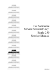
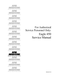
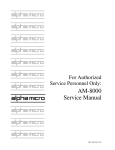
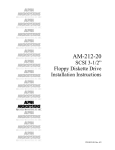
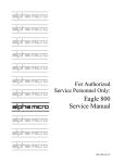
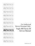
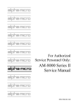
$/3+$
0,&526<67(06
5,*+7 )520 7+( 67$57
$/3+$
0,&526<67(06
5,*+7 )520 7+( 67$57
$/3+$
0,&526<67(06
5,*+7 )520 7+( 67$57
$/3+$
0,&526<67(06
5,*+7 )520 7+( 67$57
$/3+$
0,&526<67(06
5,*+7 )520 7+( 67$57
$/3+$
0,&526<67(06
5,*+7 )520 7+( 67$57
$/3+$
For Authorized
Service Personnel Only:
AM-6000
Service Manual
0,&526<67(06
5,*+7 )520 7+( 67$57
$/3+$
0,&526<67(06
5,*+7 )520 7+( 67$57
$/3+$
0,&526<67(06
5,*+7 )520 7+( 67$57
$/3+$
0,&526<67(06
5,*+7 )520 7+( 67$57
$/3+$
0,&526<67(06
5,*+7 )520 7+( 67$57
$/3+$
0,&526<67(06
5,*+7 )520 7+( 67$57
$/3+$
0,&526<67(06
5,*+7 )520 7+( 67$57
DSS-10579-00, A02
FIRST EDITION: August 1998
To re-order this document, request part number DSS-10579-00
FCC Notice
This equipment has been tested and found to comply with the limits for a Class A digital device, pursuant to Part 15 of the FCC Rules.
These limits are designed to provide reasonable protection against harmful interference when the equipment is operated in a
commercial environment. This equipment generates, uses and can radiate radio frequency energy and, if not installed and used in
accordance with the instruction manual, may cause harmful interference to radio communications. Operation of this equipment in a
residential area is likely to cause harmful interference in which case the user will be required to correct the interference at his own
expense.
Canadian Department of Communications Compliance Statement
This equipment does not exceed Class A limits per radio noise emissions for digital apparatus set out in the Radio Interference
Regulations of the Canadian Department of Communications. Operation in a residential area may cause unacceptable interference to
radio and TV reception requiring the owner or operator to take whatever steps are necessary to correct the interference.
Avis de Conformité aux Normes du Ministère des Communications du Canada
Cet équipment ne deapsse pas les limits de Classe A d'émission de bruits radioélectriques pour les appareils numeriques tels que
prescrites par le Règlement sur le brouillage radioélectrique établi par le ministère des Communications du Canada. L'exploitation faite
en milleu résidential peut entrainer le brouillage des réceptions radio et tele, ce qui obligerait le propriétaire ou l'opératour à pendre les
dispositions nécessaires pour en éliminer les causes.
Battery Warning
CAUTION: Danger of explosion if battery is incorrectly replaced. Replace only with the same or equivalent type recommended by the
manufacturer. Discard used batteries according to the manufacturer's instructions.
ATTENTION: Il y a danger d'explosion s'il y a replacement incorrect de la batterie. Remplacer uniquement avec une batterie du même
type ou d'un type recommandé par le constructeur. Mettre au rébut les batteries usagées conformément aux instructions du fabricant.
For AM-6000 systems, replace batteries with Panasonic or Ray-O-Vac BR1225 only. Use of another battery may present a risk of fire
or explosion. Replacement batteries may be ordered from your authorized Alpha Micro reseller.
Electrical Warning
This equipment contains components that can be damaged by static electricity. Follow all electronic discharge precautions when
handling the equipment. For example, touch the metal back panel of the CPU or peripheral chassis to dissipate any electrical charge
before touching the circuit boards or equipment within the chassis. After turning off power, before you open your computer chassis,
unplug the cord from the electrical outlet to guard against electrical shock.
SOFTWARE SECURITY DEVICE IDENTIFICATION NUMBER: _________________
The Alpha Micro Software Security Device (SSD) is a customized integrated circuit that personalizes the computer, providing identity
verification for it. Certain Alpha Micro and non-Alpha Micro software may require that your computer contain an SSD in order to run
software that has been customized to run only on your computer.
Please enter the identification of your SSD above. The SSD identification number should be on your computer ID label under "SSD
Serial No." (Another way of finding the number is to look at the SSD itself. The SSD is located in an integrated circuit location on the
CPU board; its identification number is printed on the SSD itself.) Software vendors may ask you for the SSD number if they are
customizing software to run only on your computer.
This document may contain references to products covered under the following U.S. Patent Number(s): 4,530,048
ALPHA MICROSYSTEMS
2722 S. Fairview Street
Santa Ana, CA 92704
Table of Contents
INTRODUCTION...................................................................................................................1
ACCESSING YOUR COMPUTER (DESKSIDE CHASSIS VERSION) ................................1
ACCESSING YOUR COMPUTER (AM-990 AND AM-990 JUMBO CHASSIS) ..................2
ELECTRONIC EQUIPMENT HANDLING PRECAUTIONS ................................................3
HARDWARE CONFIGURABLE OPTIONS ..........................................................................4
Printed Circuit Board Configuration.....................................................................................4
Remote Reset Capability......................................................................................................7
Replacing the Time and Date Battery ...................................................................................7
SSD and PROM Chip Removal ...........................................................................................8
UPGRADING AM-6000 ON-BOARD MEMORY..................................................................9
Removing Memory SIMMs..................................................................................................9
Installing the External Cache SIMM................................................................................... 10
Installing Memory SIMMs ................................................................................................. 11
Setting Memory Jumpers.................................................................................................... 12
PERIPHERAL MOUNTING (DESKSIDE CHASSIS VERSIONS) ...................................... 14
Side Mounting Bracket Removal ........................................................................................ 16
X-Bus Cable Routing......................................................................................................... 17
PERIPHERAL MOUNTING (AM-990 AND JUMBO CHASSIS VERSIONS)..................... 18
Plastic Mounting Rails....................................................................................................... 19
X-Bus Cable Routing......................................................................................................... 20
ADDITIONAL DOCUMENTATION ................................................................................... 20
Table of Figures
Figure 1: Deskside Chassis Top Cover Screws ........................................................................1
Figure 2: Deskside Chassis Top Cover Removal .....................................................................2
Figure 3: AM-990 Chassis Removal........................................................................................3
Figure 4: Static Protection Wrist Strap ....................................................................................4
Figure 5: AM-319-20 Board Configuration .............................................................................5
Figure 6: AM-176 Board Configuration...................................................................................6
Figure 7: AM-319-20 Backup Battery Removal.......................................................................8
Figure 8: SSD Chip Removal Tools ........................................................................................9
Figure 9: AM-176 SIMM Module Installation ....................................................................... 10
Figure 10: JP4 Memory Jumpers ........................................................................................... 12
Figure 11: Deskside Chassis Peripheral Mounting Positions.................................................. 14
Figure 12:Deskside Chassis Rear Panel Screw Locations....................................................... 15
Figure 13: Deskside Chassis - AM-319-20 Mounting Bracket Removal................................. 16
Figure 14: AM-990 Peripheral Mounting Area ...................................................................... 18
Figure 15: AM-990 Peripheral Mounting Rail ....................................................................... 19
Figure 16: AM-990 Attaching Mounting Rails to Peripheral.................................................. 19
Rev. A02
AM-6000 Service Manual
Page 1
INTRODUCTION
This document contains instructions which are intended only for authorized service personnel.
AM-6000 computers contain a high-output power supply, which produces current levels high
enough to make it unsafe for unauthorized persons to perform work inside the chassis.
This document describes the AM-6000 computer package in both the deskside and the AM-990 chassis.
It covers the following procedures:
• Removing your computer's cover.
• Electronic equipment handling precautions.
• Printed circuit board configuration options.
• Installing memory.
• Peripheral installation.
ACCESSING YOUR COMPUTER (DESKSIDE CHASSIS VERSION)
When adding additional equipment or servicing your computer, you will need to remove your computer's
top cover. The top cover is held in place with four Phillips-head screws on the computer's rear panel. To
remove the top cover, remove all four screws from the locations indicated in Figure 1. Once the screws
have been removed, you can slide back and remove the top cover, as shown in Figure 2.
TOP COVER SCREWS
0
SCSI
1
PRINT PORT 3
115
PRINT PORT 2
PRINT PORT 1
PRINT PORT 0
A
B
C
D
E
F
G
TX RX LINK
AUI
10 base T
SERIAL PORTS
2
1
0
SIO EXPANSION BUS
UPS
3
Figure 1: Deskside Chassis Top Cover Screws
Rev. A02
Page 2
AM-6000 Service Manual
Figure 2: Deskside Chassis Top Cover Removal
ACCESSING YOUR COMPUTER (AM-990 AND AM-990 JUMBO
CHASSIS)
When adding additional equipment or servicing your computer, you will have to gain access to the
components inside the computer. To do so, you will need to remove the computer's top cover and side
panel.
To remove the top cover:
1. Unlock the front door and swing it open.
2. Behind the front door, remove the two screws that connect the top cover to the chassis
3. Use the palm of your hand to firmly strike the rear corners of the top cover to slide it forward, in
order to release the locking tabs that hold it in place. Refer to Figure 3.
Rev. A02
AM-6000 Service Manual
Page 3
LOCKING TABS
R
E
TOP COV
TO REMOVE THE SIDE COVER,
REMOVE THESE FOUR SCREWS.
TO REMOVE THE TOP COVER,
REMOVE THESE TWO SCREWS.
Figure 3: AM-990 Chassis Removal
4. Once the top cover slides forward, pull straight up to remove it.
To remove the side panel:
1. Remove the four screws that secure the left side panel to the chassis.
2. Using the palm of your hand, firmly strike the rear edge of the side panel.
3. Once the panel slides forward, it can be removed by lifting straight up.
ELECTRONIC EQUIPMENT HANDLING PRECAUTIONS
With the AC power cord unplugged and the top cover removed, the components inside your computer are
vulnerable to damage caused by static discharge. Your body and clothing can store an electrical charge
that can damage or destroy unprotected electronic components. Before handling any computer hardware,
make sure your work area is properly protected against static discharge. There are a number of
commercially available static protection devices, like the wrist strap shown in Figure 4, designed
specifically to protect your equipment from harmful static discharge.
Rev. A02
Page 4
AM-6000 Service Manual
Figure 4: Static Protection Wrist Strap
HARDWARE CONFIGURABLE OPTIONS
The following sections summarize the configuration options available to let you tailor your hardware to
your needs. Most of these options require access to the main circuit boards inside the computer, and
should be performed only by qualified technical personnel. Contact your VAR if you need assistance.
Printed Circuit Board Configuration
The next few sections contain configuration information for the following boards:
AM-319-20
The AM-319-20 system board is used with the AM-176 board in the AM-6000. The AM-319-20 board
supports all the I/O ports used to communicate with printers, terminals, etc. The board also contains your
computer's SSD chip and other I/O related circuitry.
AM-176
The AM-176 board contains a 68060 CPU chip, one 50-pin SCSI connector and one 68-pin Wide SCSI
connector, one boot PROM, a high-performance Ethernet interface, and all of your computer's on-board
memory.
Rev. A02
AM-6000 Service Manual
Page 5
AM-319-20 Board Configuration
Figure 5 shows the AM-319-20 board configured as shipped by Alpha Micro. There is only one userconfigurable jumper on this board: the JP7 Remote Reset jumper. All other jumpers should be left in
their factory configured positions.
RJ-45 SERIAL PORTS
UPS INTERFACE
ETHERNET PORTS
TPI
ACTIVITY LEDS
AUI
F1
J2
UPS PORT
J1
T1
T2
JP3
OSC
JP4
OSC
ALPHA MICROSYSTEMS AM319-20
LNK
J3
TX
RX
PORT 3
JP1
PORT 2
SHLD/LOGC
GND
PORT 1
D1
D2
D3
J4
PORT 0
J5
PIO
PORTS
P2
LPT1
P1
LPT3
P5
LPT0
P4
LPT2
P3
G
G
-12
+12
+5
PG
P6
J7
AM-319-20
U57
G
G
G
+5
+5
+5
P7
P8
ADDRESS/DATA
P9
CONTROL/STATUS
SUPER EAGLE
REMOTE RESET
* OUT = DISABLE
IN = ENABLE
* FACTORY SET
AM-219
FLOPPY
X-BUS
SSD
U73
REM RESET
JP7
U80
+
P10
+
PWR
RESET
EAGLE
DISPLAY
PANEL
SPARE
RUN DISK
JP9 JP10
P11
JP8
P12
990
DISPLAY
PANEL
ALPHA MICRO
USE ONLY!
TOD
BATTERY
BACKUP
Figure 5: AM-319-20 Board Configuration
Rev. A02
990/AUX
DC
POWER
DISCON
JP6
FUTURE
OPTIONDO NOT
REMOVE!
DC
POWER
J6
JP5 OSC
32 16
JP5A
BUS
CLOCKDO NOT
CHANGE!
A CHANNEL B CHANNEL
SIO EXP
+5
+5
+5
-5
G
G
MC1258
AM-219
INTFC
Page 6
AM-6000 Service Manual
AM-176 Board Configuration
Your AM-176 board has been factory tested and shipped with its configuration jumpers set in their
standard default positions. Only two areas on the board may require you to change jumper settings:
• Memory size select (JP4)
• Enabling or disabling the supply of SCSI bus termination voltage (JP3)—default set at enabled.
The AM-176 board is shown in Figure 6 with all of its jumpers in their default positions. (The illustration
does not show all components on the board.)
PIN 1
ETHERNET PORT
TO AM-301-10
P4
JP1
DISC
P1
PROGRAM
DO NOT USE
P3
JP2
CD
RX
TX
NARROW
SCSI
JP3
TO AM-301-10
P6
TERM POWER
T2
PIN 1
P5
WIDE
SCSI
BANK 0 BANK 1
P2
D1 D2 D3
JP4
MEMORY CONFIGURATION
SEE TABLE 2
JP6
JP5
33
25
18
32
XCLK
JP7
JP6
CDIS
MDIS
TO
AM-301-10
JP8
JP9
50
66
68060 CPU
-
+ FAN
JP10
ALPHA MICROSYSTEMS
J1
AM-176-00 Rev C00
CACHE SIMM
LOW BANK 0
J2
LOW BANK 1
J3
HIGH BANK 0
J4
HIGH BANK 1
J5
P8
+5V
+12V P7
SERIAL
PIN 1
P9
Figure 6: AM-176 Board Configuration
Rev. A02
AM-6000 Service Manual
Page 7
Remote Reset Capability
The AM-319-20 board has an option to enable the computer's remote hardware reset. To enable remote
reset, you must do two things:
1. Install the JP7 jumper, which is shown in the AM-319-20 illustration (Figure 5). The factory
default is not installed.
2. Connect a push-button switch between pin-1 and pin-7 (signal ground) at the terminal end of the
terminal cable attached to serial port 0 on the AM-319-20 board.
Once you’ve enabled remote reset, you can reset the computer by activating the push-button switch.
Replacing the Time and Date Battery
When replacing the backup batteries, always be sure to power-down the system first! DO NOT
replace the batteries with the power on! As always when opening your computer chassis, take
proper precautions against electrostatic discharge, which can seriously damage system
components.
The AM-319-20 board uses two 3-volt lithium batteries (BR-1225) to provide power to its time/date
circuit. The batteries are no bigger than a dime (1.2 cm), and are secured side-by-side in a plastic holder
at location U80, as shown in Figure 5.
The batteries need to be replaced when the status panel displays B1 or B0. You must replace both
batteries at the same time. For battery replacement, please follow these steps:
Before turning off your computer, make a note of the current CMOS settings. Removing the
batteries will erase all CMOS data.
1. Insert a knife with a thin blade (such as a small scribe or Xacto™ knife) from the top, down
through the square hole between the right edge of the battery and the plastic holder's top piece.
(The right side is the side toward the resistor pack at RN12.)
2. Gently pry the right side of the battery so it slides to the left and pushes against the left side
spring contacts.
3. As you slide the battery to the left and it clears the plastic top hole, pry the right edge of the
battery upward and out through the hole in the top. The battery will typically "pop" up and out.
Rev. A02
Page 8
AM-6000 Service Manual
+
RN12
U80
RN12
U80
+
+
+
Figure 7: AM-319-20 Backup Battery Removal
4. Inspect the battery contacts and be sure they are clean before installing the new batteries. Use
alcohol and a cotton swab to clean them, if necessary.
5. To install a new battery, insert the edge of the battery down through the square hole and under
the left side of the plastic top. Be sure to install the new batteries with the (+) positive side up.
6. Use your finger to slide the battery to the left and down, until the right edge of the battery slips
under the right side of the plastic top. Release the battery and it should spring to the right,
securing itself under the holder's top piece.
Restoring Your CMOS Settings
Besides the time and date, the AM-319-20’s batteries also maintain the boot routine data stored in its onboard CMOS chip. Therefore, when you remove and replace the batteries, your CMOS settings will be
lost. After you install the new batteries and turn system power on, you need to access the CMOS
Configuration menu and restore your settings. Refer to the AM-6000 Owner’s Manual for detailed
instructions.
If you do not use the CMOS configuration menu to restore your settings, the system will drop into a
standard default boot routine: it will look first for a warm-boot streamer tape on SCSI device ID 3, then
for AMOS32.MON and AMOS32.INI on SCSI disk drive 0.
Once the system is up and running, log to OPR: and enter the current time and date. Reboot the system to
initialize the system up time.
SSD and PROM Chip Removal
The type of socket used for the boot PROM and SSD chips in your AM-6000 requires a special tool for
chip removal. If you ever need to remove and replace either of these chips, be sure to use the correct tool,
as shown in Figure 8.
Rev. A02
AM-6000 Service Manual
Page 9
WARNING!
The SSD chip on the
AM-319-20 and the
boot PROM on the
AM-176 board
require a
specialized tool for
their removal. If
you attempt to
remove the SSD
chip or boot PROM
using a screwdriver or
pocketknife, you could
easily damage both the
chip and the socket. This
type of chip extraction tool
is available at retail stores
specializing in electronic
components.
Figure 8: SSD Chip Removal Tools
UPGRADING AM-6000 ON-BOARD MEMORY
The AM-176 has four on-board SIMM (single inline memory module) expansion slots, which support
60ns DRAMs. It also has one on-board cache SIMM. Should you want to replace or upgrade any of these
SIMMs, first remove the existing SIMMs, then install new ones, following the procedures below.
If you change the amount of memory in your AM-6000, you must also reset the JP4 jumpers
(memory size select) according to the settings later in this chapter.
Removing Memory SIMMs
To remove a SIMM from its connector:
1. Power down the computer
2. Press out on the retainer clips and gently tilt the top of the SIMM module, so it is free of the
retainer clips.
3. Lift the SIMM out of the connector
Rev. A02
Page 10
AM-6000 Service Manual
Installing the External Cache SIMM
The external cache SIMM must only be installed in the J1 slot, labeled CACHE SIMM. Never
install memory expansion SIMMs in J1, or the cache SIMM at any other location.
To install the 64KB external cache SIMM (PDB-00701-00) on the AM-176 board:
1. Align pin-1 on the external cache SIMM module with pin-1 on connector at J1. Pin-1 on the
SIMM module is on the notched end of the module (see Figure 9 below).
2. Insert the cache SIMM module into the J1 connector at a slight angle.
3. Rotate into the upright position.
MAKE SURE THIS CURVE
IN THE SIMM CARD ALIGNS
WITH PIN-1 IN THE AM-176
SIMM CONNECTOR.
SIMM (SINGLE INLINE
MEMORY MODULE)
RETAINER
CLIP
RETAINER
CLIP
AM-176 SIMM
CONNECTOR
PIN-1 INDICATOR
Figure 9: AM-176 SIMM Module Installation
Rev. A02
AM-6000 Service Manual
Page 11
The cache SIMM will engage the retainer clips and click into position, locking in place. When properly
installed, the components on the cache SIMM module will be facing in toward the other memory
SIMMs.
Installing Memory SIMMs
The AM-6000 supports a minimum of 8MB and a maximum of 512MB of main memory. Memory is
implemented as paired SIMM modules (of equal capacity) of 4MB, 8MB, 16MB, 32MB, 64MB, or
128MB each. Use 60ns SIMMs only; 70ns SIMMs will not work. The following table shows the
allowable memory SIMM configurations (above 256MB, only some configurations are shown—others
are possible):
128MB memory SIMMs are supported only if your AM-176 board is revision B06 or C04 or later.
For this
amount of
memory…
8MB
16MB
16MB
24MB
32MB
32MB
40MB
48MB
64MB
64MB
72MB
80MB
96MB
128MB
128MB
136MB
144MB
160MB
192MB
256MB
256MB
320MB
384MB
512MB
Install these memory SIMMs…
4MB
8MB
16MB 32MB
2
---4
----2
--2
2
---4
----2
-2
-2
--2
2
---4
----2
2
--2
-2
-2
--2
2
---4
----2
----2
----2
----2
-----------2
---------
64MB
--------------2
2
2
2
2
4
--2
--
Table 1: AM-6000 Memory Configuration
Rev. A02
128MB
--------------------2
2
2
4
Page 12
AM-6000 Service Manual
To install memory expansion SIMMs on the AM-176 board, use this procedure:
1. Memory SIMMs must be installed in pairs of equal capacity.
2. Always install the SIMMs of largest capacity first.
3. Always install the first pair of SIMM modules at Bank0. Use Bank1 for a second pair of SIMM
modules.
4. Insert the first SIMM in connector J2. Align pin-1 at the notched end of the SIMM module with
pin-1 on the connector, as shown in Figure 9.
5. Insert the SIMM module into the connector at a slight angle.
6. Rotate into the upright position.
The SIMM will engage the retainer clips and click into position, locking the SIMM in place.
7. Repeat steps 4 through 6 for the second SIMM, at connector J4. If you are using a second pair of
SIMMs, insert them into J3 and J5 using the same procedure.
Setting Memory Jumpers
After installing the SIMMs, set the jumpers at location JP4 on the AM-176 board according to the table
below. As you turn on the computer, AMOS will automatically make the memory available. See Figure 6
for the location of the JP4 jumpers.
3
2
1
3
2
1
JP4
Position
BANK 0 BANK 1
Figure 10: JP4 Memory Jumpers
Rev. A02
AM-6000 Service Manual
Page 13
Memory Module Size
Combinations:
Total
Memory
2 x 4MB
4 x 4MB
2 x 8 MB
2 x 8MB + 2 x 4MB
4 x 8MB
2 x 16MB
2 x 16MB + 2 x 4MB
2 x 16MB + 2 x 8MB
4 x 16MB
2 x 32MB
2 x 32MB + 2 x 4MB
2 x 32MB + 2 x 8MB
2 x 32MB + 2 x 16MB
4 x 32MB
2 x 64MB
2 x 64MB + 2 x 4MB
2 x 64MB + 2 x 8MB
2 x 64MB + 2 x 16MB
2 x 64MB + 2 x 32MB
4 x 64MB
2 x 128MB
2 x 128MB + 2 x 32MB
2 x 128MB + 2 x 64MB
4 x 128MB
8MB
16MB
16 MB
24MB
32MB
32MB
40MB
48MB
64MB
64MB
72MB
80MB
96MB
128MB
128MB
136MB
144MB
160MB
192MB
256MB
256MB
320MB
384MB
512MB
Bank0
Settings
Position:
3
2
1
X X X
X X X
X X O
X X O
X X O
X O X
X O X
X O X
X O X
X O O
X O O
X O O
X O O
X O O
O X X
O X X
O X X
O X X
O X X
O X X
O X O
O X O
O X O
O X O
Bank1
Settings
Position:
3
2
1
O
O
O
X
X
X
O
O
O
X
X
X
X
X
O
O
O
O
X
X
X
X
X
O
X
O
X
O
O
O
X
X
X
X
X
O
X
O
X
X
O
O
O
O
O
X
X
X
X
X
O
X
O
X
X
O
O
O
X
X
O
O
O
X
O
O
O
X
X
O
X
O
Key to settings: X = Installed, O = Open
Table 2: AM-176 Memory Module Jumper (JP4) Settings
Rev. A02
Page 14
AM-6000 Service Manual
PERIPHERAL MOUNTING (DESKSIDE CHASSIS VERSIONS)
Your deskside computer cabinet can hold six half-height peripherals or three full-height 5.25"
peripherals. Filler panels in the computer front panel can be removed to allow access to some of these
peripherals. If you have six half-height peripherals, four of them can be accessed through the front panel;
if you have three full-height peripherals, two of them can be accessed through the front panel.
3.5" diskette or hard disk drives mounted in 5.25" mounting brackets are also compatible with
your computer.
The following figure shows all six peripheral mounting positions in the deskside chassis. For detailed
instructions on configuring a particular device, see the installation instructions shipped with that device.
Devices like this 3.5" diskette drive must be
mounted in a 5.25" mounting bracket before
being installed into the deskside chassis.
1
2
3
4
5
6
PERIPHERAL MOUNTING
BRACKET
Figure 11: Deskside Chassis Peripheral Mounting Positions
Rev. A02
AM-6000 Service Manual
Page 15
A peripheral is installed in the drive mounting bracket using four Phillips-head screws. To install the
peripheral mounting screws, you need access to both sides of the peripheral mounting bracket. On one
side of the cabinet, all six of the mounting positions are easily accessible. However, on the other side of
the cabinet, the AM-319-20 board and its mounting bracket block access to all but the top two mounting
positions. To ease the installation process, Alpha Micro installs peripherals starting at the top position
and working down. If your computer includes one disk drive and one tape drive, the two peripherals will
be mounted in positions 1 and 2, which are easily accessible from both sides of the chassis.
To install peripherals in mounting positions 3, 4, 5, and 6, you will need to remove the AM-319-20 board
and its mounting bracket from the chassis. At first glance, this might seem difficult, but if you follow the
procedure outlined below, it will make the task much easier.
1. Remove the three Phillips head screws where indicated in Figure 12. The three screws hold the
AM-319-20 I/O mounting bracket to the chassis rear panel.
2. Remove the threaded hex nut, as shown in Figure 12, to provide enough clearance to lift the
AM-319-20 board up and out of the chassis bottom pan.
0
SCSI
1
PRINT PORT 3
115
PRINT PORT 2
PRINT PORT 1
PRINT PORT 0
A
B
C
D
E
F
G
TX RX LINK
AUI
10 base T
SERIAL PORTS
3
2
1
0
Remove this hex nut to provide
enough clearance to lift the
AM-319-20 board up and out
of the chassis.
SIO EXPANSION BUS
UPS
Remove these screws
to unfasten the
AM-319-20 board from
the rear panel.
Figure 12:Deskside Chassis Rear Panel Screw Locations
Rev. A02
Page 16
AM-6000 Service Manual
Side Mounting Bracket Removal
Next, you need to unfasten the AM-319-20 side mounting bracket from the deskside chassis. To do so:
1. Remove the two Phillips head screws that secure the AM-319-20's side mounting bracket to the
chassis. Before you slide out the board and its mounting bracket, notice how the mounting
bracket is positioned over the two alignment tabs on the bottom of the chassis. When you
reinstall the assembly, you must make sure the mounting bracket is properly positioned over both
tabs; if it's not, it will be impossible to reinstall the two screws that hold the assembly in place.
1
POWER SUPPLY
2
3
4
5
AM-319-20 BOARD MOUNTING BRACKET
6
To remove the AM-319-20 board
mounting assembly, you must
remove these two screws.
Figure 13: Deskside Chassis - AM-319-20 Mounting Bracket Removal
2. To remove the AM-319-20 and its mounting bracket, you need to lift the bracket high enough to
clear the bottom lip on the chassis. Once you clear the bottom lip, pull the entire assembly out
just far enough to disconnect the two DC power connectors that extend between the power
supply and the AM-319-20.
Rev. A02
AM-6000 Service Manual
Page 17
3. There are a ribbon cable and a number of small wires extending between the front panel and the
display connector on the AM-319-20. Do not disconnect any of these wires; the wires are long
enough to allow you to lay down the AM-319-20 assembly on your work surface without having
to disconnect them.
4. With the AM-319-20 assembly out of the way, you will be able to access both sides of the
peripheral mounting bracket and have complete access to all six mounting positions.
5. To install a peripheral, simply slide it into one of the available mounting positions in your
chassis and install the four screws (two on each side) that hold the device in place.
6. Don't forget to attach the appropriate power and interface cables to your new peripheral.
7. After you have completed your peripheral installation, you can reinstall the AM-319-20
assembly.
The AM-319-20 side mounting bracket is an integral part of the chassis assembly. You may find
that with the bracket removed, the chassis may shift slightly, either forward or backward. To
reinstall the AM-319-20 mounting assembly, you can realign the chassis by placing one hand on
the top of the chassis and applying pressure either forward of backward. With the chassis
properly aligned, the board and its mounting assembly will slide into place.
X-Bus Cable Routing
When unfastening the AM-319-20 side mounting bracket, you should be able to lay the board assembly
down flat on the side of the chassis and out of the way without disconnecting the X-Bus cables.
However, if an X-Bus cable should come unplugged from either the AM-176 or the AM-319-20 board it
is extremely important that the cables are plugged back in correctly. If the cables are not correct the
system will not boot or run self test and one or both boards could be seriously damaged!
The X-bus cables must be connected as follows:
• C/S bus cable into P6 on the AM-176 board and P8 on the AM-319-20 board
• A/D bus cable into P4 on the AM-176 board and P7 on the AM-319-20 board
Rev. A02
Page 18
AM-6000 Service Manual
PERIPHERAL MOUNTING (AM-990 AND JUMBO CHASSIS VERSIONS)
Mounting peripheral devices in your computer is simply a matter of attaching plastic rails to the side of
the peripheral and sliding the device into its mounting position. The AM-990 chassis has mounting
locations for 12 half-height (or six full-height) 5.25" peripherals. The front door on the AM-990 chassis
has a cutout which allows access to peripheral devices using removable media. This cutout will
accommodate up to four 5.25" half-height peripherals.
Figure 14 shows the peripheral mounting area for your computer with the slots numbered 1 through 12.
PERIPHERAL MOUNTING AREA
1
2
3
4
J10
1
5
6
CPU
7
8
BATTERY
J2
9
J1
W8
10
J18
1
J7
J8
W1
J19
1
SW1
11
12
Figure 14: AM-990 Peripheral Mounting Area
Slots 3, 4, 5, and 6 are used for installing peripherals that will be accessed through the opening in the
computer door. This includes devices that use removable media, like diskette drives and magnetic tape
drives.
The first hard disk drive is mounted in slot 12, or slots 11 and 12 if it is a full-height device. A second
hard disk drive would be mounted in the next available slot above the first disk drive. The hard disk
drives are mounted in the lower part of the chassis for two reasons: to make sure the weight in the chassis
is properly distributed and to provide easy access for both power and interface cables.
Rev. A02
AM-6000 Service Manual
Page 19
Plastic Mounting Rails
The plastic mounting rails are the key to installing peripheral devices in your computer. Two rails are
required to mount a peripheral device. The rails (DWF-20652-00) are universal; they can be mounted on
either the right or left hand side of the peripheral. Figure 15 explains how the rails are installed on
various types of peripherals:
PERIPHERAL MOUNTING RAIL
DWF-20652-00
SHORT
END
LONG
END
Use the top holes for
mounting full-height devices
Use the bottom holes for
mounting half-height devices
SHORT END
For Tandberg 1/4" streaming tape drives and all hard disk drives, mount
the rails with the short end pointing toward the rear of the computer
LONG END
For DAT tape drives, mount the rails with the long end pointing toward
the rear of the computer cabinet.
Figure 15: AM-990 Peripheral Mounting Rail
Besides the rails, the peripheral mounting kit includes both standard and metric screws for compatibility
with all of Alpha Micro's 5.25” peripherals.
DWF-20652-00
MOUNTING RAIL
Figure 16: AM-990 Attaching Mounting Rails to Peripheral
Rev. A02
Page 20
AM-6000 Service Manual
X-Bus Cable Routing
You do not need to move either the AM-176 or the AM-319-20 board to mount new peripherals, which
means you won’t need to disconnect the X-Bus cables. However, if an X-Bus cable should come
unplugged from either the AM-176 or the AM-319-20 board it is extremely important that the cables are
plugged back in correctly. If the cables are not correct the system will not boot or run self test and one or
both boards could be seriously damaged!
The X-bus cables must be connected as follows:
• C/S bus cable into P6 on the AM-176 board and P8 on the AM-319-20 board
• A/D bus cable into P4 on the AM-176 board and P7 on the AM-319-20 board
ADDITIONAL DOCUMENTATION
Each peripheral device sold by Alpha Micro is covered by its own set of installation instructions. The
installation instructions include information on jumper settings, termination, and cabling. Before
installing a peripheral, make sure you read the documentation pertaining to the device.
If the documentation was not included with your peripheral device, it is probably contained on the
AlphaCD which is distributed to all Alpha Micro Value Added Resellers on a quarterly basis.
Rev. A02