1
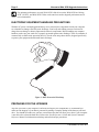
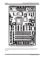
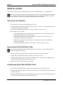
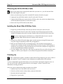
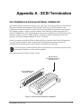
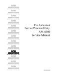
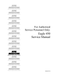
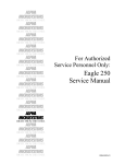
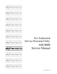
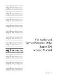
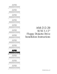
Narrow to Wide SCSI
Upgrade Instructions
PDI-00440-70, A01
FIRST EDITION: January 1998
To re-order this document, request part number PDI-00440-70
FCC Notice
This equipment has been tested and found to comply with the limits for a Class A digital device, pursuant to Part 15 of the FCC
Rules. These limits are designed to provide reasonable protection against harmful interference when the equipment is operated in a
commercial environment. This equipment generates, uses and can radiate radio frequency energy and, if not installed and used in
accordance with the instruction manual, may cause harmful interference to radio communications. Operation of this equipment in a
residential area is likely to cause harmful interference in which case the user will be required to correct the interference at his own
expense.
Canadian Department of Communications Compliance Statement
This equipment does not exceed Class A limits per radio noise emissions for digital apparatus set out in the Radio Interference
Regulations of the Canadian Department of Communications. Operation in a residential area may cause unacceptable interference
to radio and TV reception requiring the owner or operator to take whatever steps are necessary to correct the interference.
Avis de Conformité aux Normes du Ministère des Communications du Canada
Cet équipment ne depasse pas les limits de Classe A d'émission de bruits radioélectriques pour les appareils numeriques tels que
prescrites par le Règlement sur le brouillage radioélectrique établi par le ministère des Communications du Canada. L'exploitation
faite en milleu résidential peut entrainer le brouillage des réceptions radio et tele, ce qui obligerait le propriétaire ou l'opératour à
pendre les dispositions nécessaires pour en éliminer les causes.
Battery Warning
CAUTION: Danger of explosion if battery is incorrectly replaced. Replace only with the same or equivalent type recommended by
the manufacturer. Discard used batteries according to the manufacturer's instructions.
ATTENTION: Il y a danger d'explosion s'il y a replacement incorrect de la batterie. Remplacer uniquement avec une batterie du
même type ou d'un type recommandé par le constructeur. Mettre au rébut les batteries usagées conformément aux instructions du
fabricant.
For AM-6000 systems, replace batteries with Panasonic or Ray-O-Vac BR1225 only. Use of another battery may present a risk of
fire or explosion. Replacement batteries may be ordered from your authorized Alpha Micro reseller.
Electrical Warning
This equipment contains components that can be damaged by static electricity. Follow all electronic discharge precautions when
handling the equipment. For example, touch the metal back panel of the CPU or peripheral chassis to dissipate any electrical
charge before touching the circuit boards or equipment within the chassis. After turning off power, before you open your computer
chassis, unplug the cord from the electrical outlet to guard against electrical shock.
This document may contain references to products covered under the following U.S. Patent Number(s): 4,530,048
ALPHA MICROSYSTEMS
2722 Fairview Street
P.O. Box 25059
Santa Ana, CA 92704
Table of Contents
INTRODUCTION.....................................................................................................................................1
About the Wide SCSI Bus.....................................................................................................................1
COMPATIBILITY....................................................................................................................................1
ELECTRONIC EQUIPMENT HANDLING PRECAUTIONS................................................................2
PREPARING FOR THE UPGRADE .......................................................................................................2
UPGRADE PROCEDURE .......................................................................................................................3
DESKSIDE CHASSIS ..............................................................................................................................5
Removing the Chassis Cover ................................................................................................................5
Removing the 50-Pin SCSI Cable .........................................................................................................6
Installing the 68-pin Wide SCSI Bus Cable..........................................................................................6
Finishing Up..........................................................................................................................................6
AM-990 AND AM-990 JUMBO CHASSIS.............................................................................................7
Accessing Your Hardware ....................................................................................................................7
Removing the 50-Pin SCSI Bus Cable..................................................................................................8
Installing the 68-pin Wide SCSI Bus Cable..........................................................................................8
Finishing Up..........................................................................................................................................9
PEDESTAL CHASSIS............................................................................................................................10
Accessing Your Hardware ..................................................................................................................10
Removing the 50-Pin SCSI Bus Cable................................................................................................10
Installing the 68-pin Wide SCSI Bus Cable........................................................................................10
Finishing Up........................................................................................................................................11
RACK MOUNT CHASSIS.....................................................................................................................11
Accessing Your Hardware ..................................................................................................................11
Removing the 50-Pin SCSI Bus Cable................................................................................................12
Installing the 68-pin Wide SCSI Bus Cable........................................................................................12
Finishing Up........................................................................................................................................12
APPENDIX A - SCSI TERMINATION................................................................................................A-1
SCSI TERMINATION USING AN EXTERNAL TERMINATOR.....................................................A-1
ATTACHING EXTERNAL DEVICES................................................................................................A-2
TERMINATING THE INTERNAL-ONLY CABLE ...........................................................................A-2
TERMINATOR POWER......................................................................................................................A-2
PDI-00440-70, Rev. A01
INTRODUCTION
This document describes the installation procedures for a 68-pin Wide SCSI bus cable (PDB-00440-7x)
in the following four types of chassis:
• Deskside
• AM-990 and AM-990 double-wide (jumbo): these chassis accept either a standard Wide SCSI
cable or the High-Capacity Wide SCSI Internal Cable, PDB-00440-75. This cable allows up to
nine internal devices, but no external cabling.
• Pedestal
• Rack mount
After general discussions of the Wide SCSI bus, device compatibility, and electronic handling
precautions, we give general installation guidelines and specific procedures for each chassis.
About the Wide SCSI Bus
The Wide SCSI bus is twice as wide as the “narrow” SCSI bus: two bytes, or 16 bits plus 2 parity bits.
Doubling the width of the data path doubles the maximum transfer rate to 20MB per second. The Wide
SCSI bus has the following advantages:
• Disk-intensive applications are potentially faster with Wide SCSI disk drives.
• It supports up to 15 devices, where standard SCSI supports only seven, so you can potentially
work with bigger configurations.
On Alpha Micro computers which support both narrow and Wide SCSI busses, you can use only
one of the two busses at a time. You cannot install both narrow and Wide SCSI cables and use
devices attached to both.
To ensure reliable SCSI operation, the SCSI bus must be actively terminated. The passive
external terminators used on earlier AMOS systems are not adequate. Your upgrade kit includes
an active terminator for the wide bus (PRA-00222-20).
Please note that, even though the names may suggest differently, the Wide SCSI cable and
connector are physically narrower than their “narrow” SCSI counterparts.
COMPATIBILITY
You can attach both narrow and Wide SCSI-2 devices to the Wide SCSI bus. To attach narrow devices to
the Wide SCSI bus, you need an adapter (PDB-00440-91) for each device. The adapter allows the 68conductor bus cable to mate with the 50-pin connector on the SCSI-2 device and terminates the unused
signal lines on the SCSI-2 device.
PDI-00440-70, Rev. A01
Page 2
Narrow to Wide SCSI Upgrade Instructions
For optimum performance, use only Wide SCSI-2 disk drives on the Wide SCSI bus. Mixing
SCSI-1, SCSI-2, and Wide SCSI-2 disks on the same bus tends to degrade performance and is
not recommended.
ELECTRONIC EQUIPMENT HANDLING PRECAUTIONS
With the AC power cord unplugged and the top cover removed, the components inside your computer
are vulnerable to damage caused by static discharge. Your body and clothing can store an electrical
charge that can damage or destroy unprotected electronic components. Before handling any computer
hardware, make sure your work area is properly protected against static discharge. There are a number of
commercially available static protection devices, like the wrist strap shown below, designed specifically
to protect your equipment from harmful static discharge.
Figure 1: Static Protection Wrist Strap
PREPARING FOR THE UPGRADE
Any time you remove your computer’s enclosure and expose your components, we recommend you
make sure the integrity of your data is protected by making a complete backup of the data on your hard
drive. You should also make sure you have a warm boot tape that will allow you to boot if your computer
is not able to do so from the hard drive. Refer to the System Operator’s Guide and System Commands
Reference Manual for information on backup and warm boot tape procedures.
PDI-00440-70, Rev. A01
Narrow to Wide SCSI Upgrade Instructions
Page 3
Before you loosen the first screw, make sure all your data is copied onto some form of backup
media.
UPGRADE PROCEDURE
Here is a brief summary of the steps you must follow to complete your upgrade:
1. Remove your computer’s covers to expose the CPU board.
2. Remove the 50-pin SCSI bus cable from the CPU board.
3. Remove the 50-pin external SCSI terminator. Disconnect all SCSI devices.
4. Connect the 68-pin Wide SCSI cable to the CPU board and route the Wide SCSI cable in your
computer.
5. Connect all SCSI devices, using adapters to attach any narrow SCSI devices.
6. Attach the external Wide SCSI adapter plate to the SCSI cutout on your computer. For the highcapacity cable (PDB-00440-75), you attach a cover plate to the external cutout instead.
7. Connect the Wide SCSI external terminator.
8. Test system operation.
9. Replace the computer’s covers.
Your type of system may require that you modify your computer’s settings or software. Refer to
your computer owner’s manual for information specific to your system.
See Figure 2, below, for the location of the narrow and Wide SCSI connectors (at locations P2 and P5,
respectively) on the AM-176 CPU board.
PDI-00440-70, Rev. A01
Page 4
Narrow to Wide SCSI Upgrade Instructions
ETHERNET PORT
XBUS A/D CONN
P4
JP1
DISC
P1
PROGRAM
DO NOT USE
P3
JP2
JP11
RX
CD
TX
XBUS C/S CONN
P6
JP3
P2 - NARROW SCSI
CONNECTOR
T2
P5
BANK 0 BANK 1
P2
D1 D2 D3
JP4
P5 - WIDE SCSI
CONNECTOR
JP5
33
25
18
32
XCLK
JP7
JP6
CDIS
MDIS
JP8
JP9
68060 CPU
-
+ FAN
JP10
ALPHA MICROSYSTEMS
J1
AM-176-00 Rev C00
CACHE SIMM
LOW BANK 0
J2
LOW BANK 1
J3
HIGH BANK 0
J4
HIGH BANK 1
J5
P8
+5V
+12V P7
SERIAL
P9
Figure 2: AM-176 Board, SCSI (P2) and Wide-SCSI (P5) Connectors
The exact upgrade procedure differs depending on the type of chassis you are upgrading. Each chassis
type has its own set of instructions. Please turn to the correct section for the type of chassis you are
upgrading.
PDI-00440-70, Rev. A01
Narrow to Wide SCSI Upgrade Instructions
Page 5
DESKSIDE CHASSIS
This section describes how to install the Wide SCSI cable kit (PDB-00440-70) in a deskside chassis.
While your computer's hardware is exposed and the AC power cord is unplugged, the components
are vulnerable to damage caused by static discharge. Before you handle any computer hardware,
make certain your work area is properly protected against static discharge.
Removing the Chassis Cover
1. Power down your computer and unplug the power cord.
2. At the rear of the computer, remove the four screws that attach the top cover to the chassis.
3. Slide the top cover back and lift the rear edge up (as indicated by the arrows on Figure 3, below).
Remove the cover and place it out of the way.
Figure 3: Deskside Chassis Cover Removal
PDI-00440-70, Rev. A01
Page 6
Narrow to Wide SCSI Upgrade Instructions
Removing the 50-Pin SCSI Cable
Observe the routing of the existing SCSI cable before you remove it—you will route the Wide
SCSI cable along the same path.
1. Remove the bail mount clips for the external narrow SCSI connector from the rear panel.
Do not remove any cables other than the SCSI cable.
2. Unplug the 50-pin SCSI cable from P2 on the AM-176 board.
3. Unplug the 50-pin SCSI cable from all SCSI peripherals and remove the cable. Also remove any
adapters being used to attach Wide SCSI devices to the narrow cable.
Installing the 68-pin Wide SCSI Bus Cable
1. Plug the 68-pin Wide SCSI interface into P5 on the AM-176 board.
2. Route the Wide SCSI cable to the SCSI peripherals and out to the external SCSI cutout on the
rear panel. Plug the cable into each disk or tape drive.
If you are connecting narrow SCSI devices to a Wide SCSI cable, be sure to use the
appropriate adapter between the device and the cable connector.
3. Mount the new Wide SCSI cable/adapter plate assembly onto the existing SCSI cutout on the
rear panel, using the standoffs provided with your upgrade kit.
4. Make sure the Wide SCSI cable is terminated properly. This normally means plugging an
external active terminator (PRA-00222-20) into the external Wide SCSI port on the rear panel.
This terminator is included in your upgrade kit. Fasten the thumbscrews into the standoffs to
secure the terminator. See Appendix A for more information about SCSI bus termination.
5. If you are adding a disk or tape drive, don’t forget to attach the DC power cables from the power
supply to it. Refer to your computer’s service manual for peripheral installation instructions.
Finishing Up
After completing the upgrade, remember to enable Wide SCSI operation on your system. Refer to
your computer’s owner’s manual for more information on enabling Wide SCSI operation.
You have completed the upgrade. Boot and test your system before replacing the computer's cover, in
case you need to make some adjustments. Refer to your computer’s owner’s manual for more
information on testing procedures.
Once your system completes the testing procedures successfully, replace the top cover and fasten with
the four original screws.
PDI-00440-70, Rev. A01
Narrow to Wide SCSI Upgrade Instructions
Page 7
AM-990 AND AM-990 JUMBO CHASSIS
This section describes how to install the Wide SCSI cable kit, PDB-00440-71, in an AM-990 chassis, or
upgrade kit PDB-00440-72 in an AM-990 Jumbo chassis. It also covers installing the High-Capacity
Wide SCSI Internal Cable, PDB-00440-75, in either AM-990 chassis.
While your computer's hardware is exposed and the AC power cord is unplugged, the components
are vulnerable to damage caused by static discharge. Before you handle any computer hardware,
make certain your work area is properly protected against static discharge.
Accessing Your Hardware
1. Power down your computer and unplug the power cord.
2. Insert the key originally shipped with your computer in the door lock and open it.
3. To remove the top panel:
• Swing the front door open to expose the screws that hold the top cover in place. See
Figure 4, below.
• Remove the two screws that connect the top cover to the chassis.
• Remove the display key from the front panel before you attempt to remove the top cover.
• Slide the top cover forward and lift it off. Set it aside.
LOCKING TABS
R
E
TOP COV
TO REMOVE THE SIDE COVER,
REMOVE THESE FOUR SCREWS.
TO REMOVE THE TOP COVER,
REMOVE THESE TWO SCREWS.
Figure 4: AM-990 Enclosure Removal
PDI-00440-70, Rev. A01
Page 8
Narrow to Wide SCSI Upgrade Instructions
4. To remove the side panel:
• Swing the front door open to gain access to the screws that hold the side panel to the
chassis.
• Remove the four screws along the left edge (behind the front door). Lift the side panel,
slide it to the front, and place it out of the way.
• To expose the AM-176 board, remove the card cage lid (DWF-20670-00) by removing the
five screws, lifting it out, and placing it out of the way.
Removing the 50-Pin SCSI Bus Cable
Observe the routing of the existing SCSI cable before you remove it—you will route the Wide
SCSI cable along the same path.
1. Remove the bail mount clips for the external SCSI connector from the internal top panel or from
the rear of the display panel.
2. Unplug the 50-pin SCSI bus interface from P2 on the AM-176 board.
3. Unplug all the SCSI devices connected to the SCSI bus cable. Also remove any adapters being
used to attach Wide SCSI devices to the narrow cable.
4. Remove the 50-pin SCSI cable from the chassis.
Installing the 68-pin Wide SCSI Bus Cable
To install PDB-00440-71 or PDB-00440-72, use this procedure (instructions for PDB-00440-75 are
below):
1. Plug the 68-pin Wide SCSI bus cable into the connector at P5 on the AM-176 board.
2. Route the Wide SCSI bus cable over the top of the bracket so it cannot interfere with the fan on
the AM-176 board.
3. Route the Wide SCSI cable to the SCSI peripherals and out to the external SCSI cutout on the
internal top panel or on the rear of the display panel. Plug the cable into each disk or tape drive.
If you are connecting narrow SCSI devices to a Wide SCSI cable, be sure to use the
appropriate adapter between the device and the cable connector.
4. Mount the new Wide SCSI cable/adapter plate assembly onto the existing SCSI cutout using the
standoffs provided with your upgrade kit.
5. Make sure the Wide SCSI cable is terminated properly. This normally means plugging an
external active terminator into the external Wide SCSI port on the internal top panel or on the
rear of the display panel. This terminator is included in your upgrade kit. Fasten the thumbscrews
to secure the terminator. See Appendix A for more information about SCSI bus termination.
6. If you are adding a disk or tape drive, don’t forget to attach the DC power cables from the power
supply to it. Refer to your computer’s service manual for peripheral installation instructions.
PDI-00440-70, Rev. A01
Narrow to Wide SCSI Upgrade Instructions
Page 9
The High-Capacity Wide SCSI Internal Cable, PDB-00440-75, does not have an external connector. To
install it, follow these instructions:
1. Plug the 68-pin Wide SCSI bus cable into the connector at P5 on the AM-176 board.
2. Route the Wide SCSI bus cable over the top of the bracket so it cannot interfere with the fan on
the AM-176 board.
3. Route the Wide SCSI cable to the SCSI peripherals. Plug the cable into each disk or tape drive.
The final connector on the cable must have a Wide SCSI-2 device attached to it (see step 5,
below).
If you are connecting narrow SCSI devices to the cable, be sure to use the appropriate
adapter between the device and the cable connector.
4. Attach the External Connector Cover (DWF-20690-10) to the external SCSI cutout using the
screws provided with your upgrade kit.
5. Make sure the Wide SCSI cable is terminated properly. Since there is no external connector, the
last internal device on the bus must be terminated. Therefore: there must be a Wide SCSI device
with active termination in the last connector on the cable, with its termination enabled! Do not
use a narrow SCSI device as the last device, or the high nine lines of the bus will not be
terminated.
For how to enable termination for a disk drive, see the drive description document (DSS-10509xx); for a tape drive, see the drive installation instructions (PDI-00xxx-xx). See Appendix A for
more information about SCSI bus termination.
6. If you are adding a disk or tape drive, don’t forget to attach the DC power cables from the power
supply to the new peripheral. Refer to your computer’s service manual for peripheral installation
instructions.
Finishing Up
After completing the upgrade, remember to enable Wide SCSI operation on your system. Refer to
your computer’s owner’s manual for more information on enabling Wide SCSI operation.
You have completed the upgrade. Boot and test your system before replacing the computer's cover, in
case you need to make some adjustments. Refer to your computer’s owner’s manual for more
information on testing procedures.
Once your system completes the testing procedures successfully, replace the enclosure, as follows:
1. Replace the card cage lid and attach with five screws
2. Replace the side panel and tighten the four screws along the left edge
3. Replace the top cover. Tighten the two screws along the top edge.
4. Close and lock the front door.
PDI-00440-70, Rev. A01
Page 10
Narrow to Wide SCSI Upgrade Instructions
PEDESTAL CHASSIS
This section describes how to install the Wide SCSI cable kit (PDB-00440-73) in a pedestal chassis.
While your computer's hardware is exposed and the AC power cord is unplugged, the components
are vulnerable to damage caused by static discharge. Before you handle any computer hardware,
make certain your work area is properly protected against static discharge.
Accessing Your Hardware
1. Power down your computer and unplug the power cord.
2. Lay the computer on its side with the bezel facing away from you. We recommend that you place
the chassis on a padded work surface.
3. Let the feet from the pedestal hang over the edge of a table, or remove them.
4. Remove the cover, as follows:
• Looking at the computer from the back, remove the three screws on the right side of the
cabinet that hold the top cover to the chassis.
• Remove the top three screws on the left side of the cabinet. Two of these screws are
attached to the computer's mounting feet.
• Remove the small screw near the center top of the back panel, just to the right of the
chassis slot marked E.
• Lift the cover slightly and slide it off toward you. Remove it and set it aside.
Removing the 50-Pin SCSI Bus Cable
Observe the routing of the existing SCSI cable before you remove it—you will route the Wide
SCSI cable along the same path.
1. Remove the bail mount clips for the external SCSI connector from the rear panel.
2. Unplug the 50-pin SCSI bus interface from P2 on the AM-176 board.
3. Unplug all the SCSI devices connected to the SCSI bus cable. Also remove any adapters being
used to attach Wide SCSI devices to the narrow cable.
4. Remove the 50-pin SCSI cable from your system.
Installing the 68-pin Wide SCSI Bus Cable
1. Plug the 68-pin Wide SCSI bus cable into the connector at P5 on the AM-176 board.
2. Route the Wide SCSI bus cable over the top of the bracket so it cannot interfere with the fan on
the AM-176 board.
3. Route the Wide SCSI cable to the SCSI peripherals and out to the external SCSI adapter plate on
the rear panel. Plug the cable into each disk or tape drive.
PDI-00440-70, Rev. A01
Narrow to Wide SCSI Upgrade Instructions
Page 11
If you are connecting narrow SCSI devices to a Wide SCSI cable, be sure to use the
appropriate adapter between the device and the cable connector.
3. Mount the new Wide SCSI cable/adapter plate assembly onto the existing SCSI cutout using the
standoffs provided with your upgrade kit.
4. Make sure the Wide SCSI cable is terminated properly. This normally means plugging an
external active terminator into the external Wide SCSI port on the rear panel. This terminator is
included in your upgrade kit. Fasten the thumbscrews to secure the terminator. See Appendix A
for more information about SCSI bus termination.
5. If you are adding a disk or tape drive, don’t forget to attach the DC power cables from the power
supply to it. Refer to your computer’s service manual for peripheral installation instructions.
Finishing Up
After completing the upgrade, remember to enable Wide SCSI operation on your system. Refer to
your computer’s owner’s manual for more information on enabling Wide SCSI operation.
You have completed the upgrade. Boot and test your system before replacing the computer's cover, in
case you need to make some adjustments. Refer to your computer’s owner’s manual for more
information on testing procedures.
Once your system completes the testing procedures successfully:
1. Attach the computer cover with the existing seven screws.
2. Reconnect the power cord.
RACK MOUNT CHASSIS
This section describes how to install the Wide SCSI cable kit (PDB-00440-74) in a rack mount chassis.
While your computer's hardware is exposed and the AC power cord is unplugged, the components
are vulnerable to damage caused by static discharge. Before you handle any computer hardware,
make certain your work area is properly protected against static discharge.
Accessing Your Hardware
1. Power down your computer and unplug the power cord.
2. Unplug and clearly mark all cables from the rear panel.
3. Unlatch slides and carefully slide the rack out of the system.
4. Remove the seven screws that hold the top cover to the chassis.
5. Lift the top cover off and place it out of the way.
PDI-00440-70, Rev. A01
Page 12
Narrow to Wide SCSI Upgrade Instructions
Removing the 50-Pin SCSI Bus Cable
Observe the routing of the existing SCSI cable before you remove it—you will route the Wide
SCSI cable along the same path.
1. Remove the bail mount clips for the external SCSI connector from the rear panel.
2. Unplug the 50-pin SCSI bus interface from P2 on the AM-176 board.
3. Unplug all the SCSI devices connected to the SCSI bus cable. Also remove any adapters being
used to attach Wide SCSI devices to the narrow cable.
4. Remove the 50-pin SCSI cable from the chassis.
Installing the 68-pin Wide SCSI Bus Cable
1. Plug the 68-pin Wide SCSI bus cable into the connector at P5 on the AM-176 board.
2. Route the SCSI cable from P5 on the AM-176 board to the SCSI peripherals and out to the
external SCSI adapter plate on the rear panel. Plug the cable into each SCSI disk or tape drive.
If you are connecting narrow SCSI devices to a Wide SCSI cable, be sure to use the
appropriate adapter between the device and the cable connector.
3. Mount the new Wide SCSI cable/adapter plate assembly onto the existing SCSI cutout on the
rear panel using the standoffs provided with your upgrade kit.
4. Make sure the Wide SCSI cable is terminated properly. This normally means plugging an
external active terminator into the external Wide SCSI port on the rear panel. This terminator is
included in your upgrade kit. Fasten the thumbscrews to secure the terminator. See Appendix A
for more information about SCSI bus termination.
5. If you are adding a disk or tape drive, don’t forget to attach the DC power cables from the power
supply to it. Refer to your computer’s service manual for peripheral installation instructions.
Finishing Up
After completing the upgrade, remember to enable Wide SCSI operation on your system. Refer to
your computer’s owner’s manual for more information on enabling Wide SCSI operation.
You have completed the upgrade. Boot and test your system before replacing the computer's cover, in
case you need to make some adjustments. Refer to your computer’s owner’s manual for more
information on testing procedures.
Once your system completes the testing procedures successfully:
1. Attach the top cover to the chassis with seven screws.
2. Slide the rack back into the cabinet. Make certain the slides latch.
3. Reconnect the back panel cables.
4. Plug in the AC power cable.
PDI-00440-70, Rev. A01
Appendix A - SCSI Termination
SCSI TERMINATION USING AN EXTERNAL TERMINATOR
The SCSI bus must be terminated at each end of the cable. The CPU board terminates one end of the bus.
The preferred method of terminating the other end of the SCSI bus in an AMOS computer is the
installation of an external terminator. In April 1993, the external SCSI bus terminator became standard
on all AMOS computers. Using an external terminator makes installing an add-on subsystem (like a
portable CD-ROM drive) easier, eliminating the need to remove terminators from a SCSI device located
in the host computer. On newer AMOS computers, including all models which support Wide SCSI
operation, this external terminator must be an “active” terminator.
An active terminator for the Wide SCSI bus (PRA-00222-20) is included in the Wide SCSI upgrade kit.
To use the external terminator, make sure none of the SCSI peripherals inside the computer are
terminated. The termination power for the SCSI bus is provided by the CPU board.
If you are using the external terminator and one of the SCSI devices inside the computer also has
its terminators installed, you will experience problems.
The external terminator is shown in Figure 5, below:
PRA-00222-20
EXTERNAL SCSI BUS
TERMINATOR
SCSI CONNECTOR
ON BACK PANEL
Figure 5: Active External Terminator Installation
PDI-00440-70, Rev. A01
Page A-2
Appendix A
Figure 5 shows an active external Wide SCSI connector and thumbscrews for holding the terminator in
place. This configuration is used on almost all of Alpha Micro's currently available product. The
terminator is installed by sliding it over the connector and fastening the thumbscrews to the standoffs in
the terminator.
ATTACHING EXTERNAL DEVICES
To attach an external SCSI device, you must remove the terminator from the external SCSI port.
However, you must make sure the SCSI bus is still terminated at both ends. To do so, install the external
active terminator in the unused SCSI I/O port of the external SCSI device.
Attaching an external narrow SCSI device, such as a CD-ROM drive, to a system using the Wide SCSI
bus is a special case. You must make sure all 16 lines of the Wide SCSI bus are properly terminated. To
do so:
1. Use an external wide to narrow SCSI cable which actively terminates the “high” nine lines of the
Wide SCSI bus. Alpha Micro offers this cable in both three foot and six foot lengths
(PDB-00440-80 and PDB-00440-81).
2. Plug a narrow active external terminator (PRA-00222-21) into the unused SCSI I/O port of the
external device. This terminates the “low” half of the SCSI bus.
Notice that, in this configuration, the Wide SCSI active external terminator (PRA-00222-20), which is
normally plugged into the external SCSI port, is not used.
TERMINATING THE INTERNAL-ONLY CABLE
The High-Capacity Wide SCSI Internal Cable (PDB-00440-75) does not attach to the external SCSI port,
and therefore cannot use an external SCSI terminator. When using this cable you must terminate the bus
by plugging a Wide SCSI device with active terminators (not a narrow device using an adapter) into the
last connector on the cable, and enabling termination on that device. For proper termination, the device
must be in the connector at the physical end of the cable, not just be the last device on the bus.
For a disk drive, see the drive description document (DSS-10509-xx) for how to enable termination; for a
tape drive, see the drive installation instructions (PDI-00xxx-xx).
TERMINATOR POWER
For information on how to configure terminator power, see the following documents:
• SCSI Disk Drives Installation Instructions, PDI-00436-20, revision A12 or later.
• AM-625/626/627 SCSI 1/4" Streaming Tape Drive Installation Instructions, PDI-00625-00,
revision A05 or later.
• AM-647 DAT Tape Drive Installation Instructions, PDI-00647-00, revision A02 or later.
• AM-650 SCSI High-Capacity ¼” Streaming Tape Drive Installation, PDI-00650-00.
• The configuration document accompanying your disk drive, DSS-10509-xx.
PDI-00440-70, Rev. A01