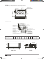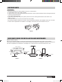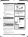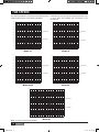
1
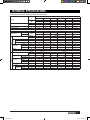
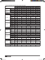
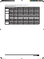
Installation & Owner’s Manual
MINISPLIT
AIR BLOWER
MODELS
YUHC 18-60
YUKC 07-18
EN 035M00065-000
J368-EN.indd 1
2/1/07 9:40:52 AM
CONTENTS
Safety Precautions ...................................................3
Part Names ................................................................4
Technical Specifications ..........................................5
Outdoor Unit Dimensions ........................................9
Preparation Before Installation ............................. 10
Installation...............................................................10
Condensate Drainage ............................................14
Refrigerant Piping Connects ................................. 15
Fan Speeds .............................................................16
Wiring Diagrams .....................................................17
Defrosting Operation..............................................20
Please read this installation
manual carefully before starting
the installation. It will tell you
necessary information.
Service and Maintenance ......................................20
Operation Tips ........................................................21
Trouble Shooting Guide .........................................22
Declaration of Conformity .....................................23
Refrigerant
Model
Set
Outdoor
Indoor
DC INVERTER R-410A
18-24
36-48
60
YUHCxxDUBAAR-K
YUHCxxDUBACR-K
YUHCxxDSBACR-K
YUJCxxDU-BAR
YUJCxxDU-BCR
YUJCxxDS-BCR
YUKCxxDU-BAR-K
YUKCxxDU-BCR-K
YUKCxxDS-BCR-K
Multi Inverter R-410A
50Hz/1Ph
Outdoor
RRJCxxAA-AAA
Indoor
YUKCxxAA-AAR
Standard
Refrigerant
R-410A
Model
Set
Quality POLICY
We will continuously strive to satisfy
our customers with consistent reliability in product, service and support
through superior quality, service
culture and distinctive technology.
J368-EN.indd 2
18-24
30-60
YUHCxxFUAAAR
YUHCxxFUAACR
Outdoor
YUJCxxFU-AAR
YUJCxxFU-ACR
Indoor
YUKCxxFU-AAR
YUKCxxFU-ACR
With Low Ambient Kit
Refrigerant
Model
Set
R-410A
18-24
30-60
YUHCxxFUBAAR
YUHCxxFUBACR
Outdoor
YUJCxxFU-AAR
YUJCxxFU-ACR
Indoor
YUKCxxFU-AAR
YUKCxxFU-ACR
2/1/07 9:40:52 AM
REQUIRED TOOLS
1.
2.
3.
4.
5.
6.
7.
8.
Screw driver
Hexagonal wrench
Torque wrench
Spanner
Reamer
Hole core drill
Tape measure
Thermometer
EXTENDED PARTS
9.
10.
11.
12.
13.
14.
15.
Manifold gauge
Gas leak detector
Vacuum pump
Pipe clamp
Pipe cutter
Flare tool set
Electrical circuit tester
1.
2.
3.
4.
Refrigerant Pipe : See Technical Specification
Pipe insulation material (Polyethylene foam 9 mm thick)
Vinyl tape
Putty
SAFETY PRECAUTIONS
• Please read this installation manual carefully before starting installation of the unit.
• This air conditioning system contains refrigerant under pressure, rotating parts and electrical connection which
may be dangerous and can cause injury. Installation and maintenance of this air conditioning system should only
be carried out by trained and qualified personnel.
• After unpacking, please check the unit carefully for possible damage.
• Before undertaking any work on the unit, make sure that the power supply has been disconnected.
WARNING & CAUTIONS
Danger
CAUTION
Do not attempt to install this unit by yourself. This unit requires installation by
qualified persons.
DANGER
Do not attempt to service the unit yourself. This unit has no user serviceable
components. Opening or removing the cover will expose you to dangerous
voltage. Turning off the power supply will not prevent potential electric shock.
DANGER
Never put hands or objects into the Air Outlet of indoor or outdoor units. These
units are installed with a fan running at high speed. To touch the moving fan will
cause serious injury.
No
DANGER
To avoid the risk of serious electrical shock, never sprinkle or spill water or liquids on unit.
WARNING
Ventilate the room regularly while the air conditioner is in use, especially if there
is also a gas appliance in use in this room. Failure to follow these directions may
result in a loss of oxygen in the room.
WARNING
To prevent electric shock, turn off the power or disconnect the power supply
plug before beginning any cleaning or other routine maintenance. Follow the
directions for cleaning in this manual.
WARNING
Do not use liquid cleaners or aerosol cleaners, use a soft and dry cloth for
cleaning the unit. To avoid electric shock, never attempt to clean the unit by
sprinkling water.
WARNING
Thinner
Do not use caustic household drain cleaners in the unit. Drain cleaners can
quickly destroy the unit components (drain pan and heat exchanger coil, etc.)
WARNING
For proper performance, operate the unit in temperature and humidity ranges
indicated in this manual. If the unit is operated beyond these conditions, it may
cause abnormal functions of the unit or dew dripping from the unit.
ENGLISH
J368-EN.indd 3
3
2/1/07 9:40:54 AM
PART NAMES
INDOOR UNIT
I
A
J
K
E
L
N
M
Display Panel
B
F
G
OUTDOOR UNIT
D
H
E
C
■ INDOOR & OUTDOOR UNIT
A. Indoor unit
B. Outdoor unit
C. Remote controller
D. Air-in
E. Air-out
F. Air inlet
G. Connecting pipe
H. Drain hose
■ DISPLAY PANEL
I. Infrared signal receiver
J. Emergency button
K. Running indicator
L. Timer indicator
M. Frost indicator (cooling and heating type)
or fan indicator (cooling only type)
N. Pump indicator
NOTE
All the pictures in this manual are for explanation
purpose only. They may be sightly different from the
air conditioner you purchased. The actual shape shall
prevail.
4
J368-EN.indd 4
ENGLISH
2/1/07 9:40:55 AM
TECHNICAL SPECIFICATIONS
Technical Specifications : Duct Type YUHC “R-410A” -50Hz
Indoor
Unit
Models
Outdoor
Unit
YUKC
18
30
36
48
60
48
60
YUJC
18
V/Ph/Hz
Power Supply
24
24
30
36
220-240/1/50
380/3/50
Ph
1
1
3
3
3
3
Power Consumption
W
1,900/1,900
2,560/2,500
3,250/3,250
3,700/3,350
4,700/4,900
6,000/6,000
Running Current
A
8.8/8.8
12.2/11
5.5/5.5
6.5/5.8
8.2/8.6
9.8/9.8
Refrigerant Type
R-410A
Refrigerant Charge
Noise level
gr
Indoor
Fan
2,600
3,100
3,100
4,000
4,200
38
38
44
44
46
47
48
55
57
57
58
58
V/Ph/Hz
Power Supply
Indoor Unit
dB(A)
Outdoor
2,050
Air flow
220-240/1/50
Ph
1
1
1
1
1
1
m3/h
1,160
1,460
2,070
2,070
2,400
2,800
Input Power
W
117
170
118
118
118
227
Running Current
A
0.53
0.77
0.54
0.54
0.54
1.03
Dimension
Height
mm
300
300
300
300
300
320
Width
mm
1,000
1,000
1,350
1,350
1,350
1,350
Depth
mm
800
800
800
800
800
800
kg
36
38
48
48
50
70
Weight
System Operation Control
V/Ph/Hz
Power Supply
Dimension
Ph
Qty
220-240/1/50
380/3/50
1
1
3
3
3
3
1
1
1
1
1
1
Compressor Type
Rotary
Scroll
Height
mm
695
860
960
960
1,245
1,245
Width
mm
845
895
990
990
940
940
Depth
mm
335
330
360
360
360
360
kg
55
79
101
101
110
110
Weight
Piping
Outdoor Unit
Compressor
Wireless Control with LCD Display
Type
Pipe Size
Flare + Nuts
Suction
inch
1/2
5/8
3/4
3/4
3/4
3/4
Liquid
inch
1/4
3/8
1/2
1/2
1/2
1/2
ENGLISH
J368-EN.indd 5
5
2/1/07 9:40:56 AM
Technical Specification: Ducted Dc Inverter “YUHC” R-410A, 50Hz.
Model
Power supply
Capacity
Input
Rated current
Capacity
Heating
Input
Rated current
Max. input consumption
Max. current
Starting current
Type
Input
Rated current (RLA)
Locked rotor
Compressor
Amp (LRA)
Protector
Capacitor
Refrigerant oil
Type
Input
Indoor fan motor
Capacitor
Speed (Hi/Me/Lo)
Number of rows
Fin spacing
Fin type
Indoor coil
Tube outside dia.
Material Type
Coil length x
height x width
Indoor air flow (Hi/Me/Lo)
Indoor external static pressure (Hi)
Indoor noise level (Hi/Me/Lo)
Dimension
(WxHxD)
Indoor unit
Packing
(WxHxD)
Net/Gross weight
Input
Outdoor fan
Capacitor
motor
Speed
Number of rows
Fin spacing
Fin type
Outdoor coil
Tube outside dia.
Tube Material
Coil length x
height x width
Outdoor air flow
Outdoor noise level
Cooling
Outdoor unit
Refrigerant R-410A
Throttle type
Refrigerant piping
6
J368-EN.indd 6
Dimension
(WxHxD)
Packing
(WxHxD)
Net/Gross weight
Liquid side/
Gas side
Set
Indoor
Outdoor
V-Ph-Hz
Btu/h
W
A
Btu/h
W
A
W
A
A
W
A
A
YUHC18DUBAAR-K
YUHC24DUBAAR-K
YUKC18DU-BAR-K
YUKC24DU-BAR-K
YUJC18DU-BAR
YUJC24DU-BAR
220~240-1-50
220~240-1-50
18,000
24,000
1,570
2,130
7
10
21,000
28,000
1,630
2,190
7
10
2,600
2,800
10
11
1
1
DC Inverter Rotary
1,650
1,650
8
8
28
µF
ml
50
480
W
µF
r/min
117
3
900/800/690
3
2
mm
mm
28
YUHC36DUBACR-K
YUKC36DU-BCR-K
YUJC36DU-BCR
380V~3~50Hz
36,000
3,260
9
40,000
3,120
8
3,560
10
1
YUHC60DSBACR-K
YUKC60DS-BCR-K
YUJC60DS-BCR
380V~3~50Hz
60,000
4,840
11
62,000
4,800
11
5,950
16
1
3,665
8
YUHC48DUBACR-K
YUKC48DU-BCR-K
YUJC48DU-BCR
380V~3~50Hz
48,000
4,250
11
53,000
4,140
11
4,750
13
1
DC Inverter Scroll
3,665
8
28
28
28
50
500
50
500
324
10
870/770/700
3
2
160
10
870/770/700
3
2
Thermal
50
50
480
500
AC Motor
170
118
7
3
1,100/1,020/900
820/695/620
3
3
2
2
Hydrophilic aluminium
Ø9.52
Innergroove tube
3,665
8
mm
800×254×66
800×254×66
1,150×254×66
1,150×254×66
1,150×305×66
m3/h
Pa
dB(A)
1,020/870/700
40
50/-/-
1,275/1,170/1,030
40
53/-/-
2,070/1,950/1,860
70
49/47/44
2,400/2,300/2,200
70
51/47/44
2,800/2,700/2,600
96
52/48/46
mm
1,095×805×290
1,095×805×290
1,350×298×800
1,350×320×800
1,350×320×800
mm
1,205×940×370
1,205×940×370
1,555×940×370
1,555×440×940
1,555×440×940
kg
W
µF
r/min
38/45
129
3
770
2
2
38/45
150
3
800
2
2
48/57
307
10
740
1
2
Hydrophilic aluminium
Ø9.52
Innergroove tube
70/80
150×2
3.5×2
800
1
2
70/80
150×2
3.5×2
800
1
2
mm
mm
mm
630×660×44
620×813×44
955×915×22
715×610×22
1150×305×66
m3/h
dB(A)
2,400
56
3,000
55
5,000
57
6,000
58
6,000
58
mm
840×677×310
894×860×302
990×960×340
940×1,245×340
940×1245×340
mm
965×770×395
1,043×915×395
1,120×1015×435
1,058×1300×435
1,058×1,300×435
kg
g
62.5/66.5
1,650
72/76.5
2,200
106/111
2,600
EXV&Capillary
117/126
3,550
112/127
4,200
mm
6.35/12.7
9.53/16
9.53/16
9.53/16
9.53/16
ENGLISH
2/1/07 9:40:56 AM
TECHNICAL SPECIFICATION: EVEREST MULTI INVERTER “YUKC-RRJC” 50Hz
Indoor Unit Duct Type YUKC 07-18
Model
YUKC 07AA-AAR
YUKC 09AA-AAR
YUKC 12AA-AAR
YUKC 18AA-AAR
Ph-V-Hz
1Ph, 220-240V~, 50Hz
1Ph, 220-240V~, 50Hz
1Ph, 220-240V~, 50Hz
1Ph, 220-240V~, 50Hz
Cooling Capacity
BTU/h
7,000
9,000
12,000
18,000
Heating Capacity
BTU/h
8,000
11,000
14,000
21,000
Power input
w
40
40
40
65
Input
W
38
38
38
63
Capacitor
µF
1.0µF/450V
1.0µF/450V
1.0µF/450V
2.5µF/450V
r/min
735/650/560
735/650/560
735/650/560
930/830/660
2
2
2
2
mm
1.5
1.5
1.5
1.7
mm
Ø7
Ø7
Ø7
Ø9.53
700x26x350
800x254x44
Power supply
Capacity
Indoor fan
motor
Speed (Hi/Mi/Lo)
Number of rows
Fin spacing
Fin type
Indoor coil
Tube outside dia.
Hydrophilic aluminium
Tube Material
Coil length x height
x width
Innergroove tube
mm
700x26x350
4
4
4
3
Indoor air flow (Hi/Mi/Lo)
m3/h
480/410/360
480/410/360
580/480/400
660/550/480
Indoor noise level (Hi/Mi/Lo)
Number of circuits
Pipe size
Indoor unit
700x26x350
dB(A)
35/32/30
36/33/30
38/35/33
40/38/35
Liquid side/ Gas side
mm
Ø6.35/Ø9.53
Ø6.35/Ø9.53
Ø6.35/Ø12.7
Ø6.35/Ø12.7
Dimension (W*H*D)
mm
955×210×385
955×210×385
955×210×385
1,301X210X385
Packing (W*H*D)
mm
1,114x277x469
1,114x277x469
1,114x277x469
1,114x277x469
Net/Gross weight
Kg
15/19
15/19
15/19
18/22
ENGLISH
J368-EN.indd 7
7
2/1/07 9:40:56 AM
Outdoor Unit Multi Inverter RRJC 18-27
Model
RRJC 18AA-AAA
Indoor Units Combination
Single
Power supply
Ph-V-Hz
1Ph, 220-240V~, 50Hz
18,000
7,000~12,000
16,000~24,000
27,000
2,050~3,517
5,275
2,000~3,500
4,690~7,000
7,913
Input
W
1,000~1,300
1,813
1,000~1,300
2,570~2,850
2,806
Rated current
A
4.8~6.5
11.5
4.8~6.5
11.7~13.5
13.5
Btu/h
9,000~14,000
21,000
10,000~14,000
24,000~27,000
30,000
W
2,638~4,103
6,155
2,900~4,100
7,000~7,900
8,792
Input
W
1,300~1,600
2,038
1,300~1,600
2,100~2,750
2,739
Rated current
A
6.3~7.8
11.0
6.3~7.8
11.0~13.2
13.2
W
Max. current
3,200
A
Type
20
Rotary inverter
W
1,690
1,690
A
11.6
11.6
Locked rotor Amp (LRA)
A
60
60
Internal
Internal
Capacitor
µF
85µF/250V
85µF/250V
Refrigerant oil
ml
750
750
Input
W
148
148
Capacitor
µF
3
3
r/min
775
775
2
2
mm
1.7
1.7
Hydrophilic aluminium
Hydrophilic aluminium
Speed
Fin spacing
Fin type
Outdoor coil Tube outside dia.
mm
Tube Material
Coil length x height x width
mm
Number of circuits
Outdoor air flow
m3/h
Outdoor noise level
Ø9.53
Ø9.53
Innergroove tube
Innergroove tube
776×660×22
776×660×22
2
2
2,500
2,500
dB(A)
60
60
Dimension (WxHxD)
mm
845X695X335
845X695X335
Packing (WxHxD)
mm
965X772X405
965X772X405
Net/Gross weight
kg
71/74
72/76
g
2,100
2,250
Liquid side/ Gas side
mm
Ø6.35/Ø9.53
3 X Ø6.35/Ø9.53
Transfer Connector (9.53→12.7)
Refrigerant Type R-410A
Refrigerant
piping
20
Rotary inverter
Rated current (RLA)
Number of rows
Outdoor
unit
3,200
Input
Thermal protector
Outdoor fan
motor
Treble
7,000~12,000
Max. input
Compressor
Double
1Ph, 220-240V~, 50Hz
W
Capacity
Heating
Single
Btu/h
Capacity
Cooling
RRJC 27AA-AAA
Double
mm
2
2
Max. refrigerant pipe length
m
15 (each indoor unit)
15 (each indoor unit)
Max. difference in level
m
10 (each indoor unit)
10 (each indoor unit)
Remark : The above design and specifications are subject to change without prior notice for product improvement.
OPERATING TEMPERATURE
Temperature
Room temperature
Outdoor temperature
Mode
Cooling operation
Heating operation
Drying operation
17°C~32°C
21°C~43°C
0°C~30°C
-7°C~24°C
17°C~30°C
11°C~43°C
CAUTIONS
1. If air conditioner is used outside of the above conditions, certain safety protection features may come into operation
cause the unit to function abnormally.
2. Room relative humidity less than 80%. If the air conditioner operates in excess of this figure, the surface of the
air conditioner may attract condensation. Please set the vertical air flow louver to its maximum angle (Vertically to
the floor), and set HIGH fan mode.
3. Optimum performance will be achieved within these operating temperature.
8
J368-EN.indd 8
ENGLISH
2/1/07 9:40:57 AM
OUTDOOR UNIT DIMENSIONS
YUJC 18
YUJC 24
313
845
300
895
135
351.2
860
695
301.5
560.1
163
590
335
330
125
235
141.5
YUJC 30-36
YUJC 48-60
336.4
400
940
1,245
960
990
624
360
360
181.4
650
RRJC 18-27
688
790
300
310
520
ENGLISH
J368-EN.indd 9
9
2/1/07 9:40:59 AM
DC Inverter R-410A
mm
A
B
C
D
E
H
18
840
560
335
360
310
677
24
894
590
333
355
302
860
36
990
624
366
396
340
960
48
940
600
376
400
340
1,245
REMARK
H
MODEL
A
R-410A
D
C
E
B
PREPARATION BEFORE INSTALLATION
• Before doing any work, check the interior power supply cord and the main breaker capacity are sufficient and the
installation area is sufficient and complies with the requirements.
• Check that the power supply available agrees with name plate voltage.
• Electrical work, wiring and cables must be performed in compliance with national and local wiring codes and standard.
• Do not use the extension cables. In the case extended cables are needed, use the terminal block.
INSTALLATION
■ Installation place
The indoor unit must be installed such that there is no short circuit of the cool discharge. Comply to the installation
clearance recommended. Do not put the indoor unit where there is direct sunlight on unit. Make sure the location is
suitable for piping and drainage.
INDOOR UNIT
YUKC 07-12
380
220
175
25
63
87
210
55
102
210
Air Outlet
715
870
Drain port Ø25
Refrigerant pipe
Gas Side Ø9.0
Refrigerant pipe
Liquid Side Ø9.53
915
100
380
268
148
Ø100
>250mm
870
Fresh
air inlet
>500mm
10
J368-EN.indd 10
>500mm
ENGLISH
2/1/07 9:41:10 AM
YUKC 18-48
The positioning of ceiling hole and indoor unit and hanging screw bolt:
Air outlet
N-Ø200
Main body : A
Hanging Screw bolt
70
4-M10 Site configuration
Distance between bolts: B
115
175
H
60
80
C
5
440-640
J=MxK
Ceiling hole: D
Panel: E
Install the main body:
300
Main body: 800
720
630
Connecting point of
refrigerant pipe
(Liquid side ØG)
160
285
298
100
120
440
Connecting point of
refrigerant pipe
335
30
(Gas side ØF)
Dust proof net
(Additional purchase)
Connecting point of drain pipe
Canvas air passage
(Additional purchase)
450
Ceiling hole 470
Panel
(Additional purchase)
Panel 500
Capacity (Btu/h)
12000-18000
24000
30000-48000
A
B
1082 1052
C
1115
D
E
1087 1408
1350 1400 1380 1400 1430
F
G
12.7
6.35
16
9.53
19
12.7
H
I
J
K
M
N
—
—
—
—
—
—
252
35
930
310
3
4
ENGLISH
J368-EN.indd 11
11
2/1/07 9:41:11 AM
YUKC 60
The positioning of ceiling hole and indoor unit and hanging screw bolt:
Air outlet
N-Ø200
Main body : A
Distance between bolts: B
J=MxK
Hanging Screw bolt
70
4-M10 Site configuration
440-640
150
H
60
80
5
C
Ceiling hole: D
Panel: E
Install the main body:
Main body: 800
210
Distance between bolts: 565
720
630
A
B
C
100
30
Ceiling hole 470
Panel 500
D
E
1350 1400 1380 1400 1430
Ø125 Plank (inside)
(For air delivery from outside)
Dust proof net
(Additional purchase)
Canvas air passage
(Additional purchase)
Panel
(Additional purchase)
450
Entrances and exits
for communication
lines of indoor and outdoor units
60000
300
155
335
Connecting point
of drain pipe
Capacity (Btu/h)
80
70
Connecting point of cold
medium pipe
(liquid side ØG)
Fixed screw
210
90 120
(Air side ØF)
305
Connecting point of cold
medium pipe
170
320
300
F
G
H
I
J
K
M
N
19
12.7
252
35
930
310
3
4
When using a back-air installation, please refer to the following:
B
A
Back panel layout
YUKC 18-48
12
J368-EN.indd 12
I
320
250
205
300
127
N-250x393.8
I
A
Back panel layout
YUKC 60
ENGLISH
2/1/07 9:41:13 AM
OUTDOOR UNITS
CAUTIONS
• Keep this unit away from direct radiation of the sun or other heaters.
• If unavoidable, please cover it with a shelter.
• In places near coast or with a high attitude where the wind is violent, please install the outdoor unit against the wall
to ensure normal performance.
Use a baffle when necessary.
• In the case of extremely strong wind, please prevent the air from flowing backwards into the outdoor unit.
(Refer to chart 1)
• Locate the outdoor unit as close to the indoor unit as possible.
• The minimum distance between the outdoor unit and obstacles described in the installation chart does not mean
that the same is applicable to the situation of an airtight. Leave open two of three directions A, B, C.
Strong wind
Chart 1
NECESSARY ROOM FOR INSTALLATION AND MAINTENANCE
(Refer to chart 2, chart 3)
Remove the obstacles nearby to prevent the performance from being impeded by too little of air circulation.
The minimum distance between the outdoor unit and obstacles described in the installation chart does not mean that
the same is applicable to the situation of an airtight room. Leave open two of the three directions (A, B, C).
>30 cm.
Air inlet
>30 cm.
>60 cm.
(Wall or obstacle)
Fix with bolt
Maintain channel
Air inlet
>200 cm.
>60 cm.
Air outlet
Deep foundation
Necessary width
Chart 2
Chart 3
ENGLISH
J368-EN.indd 13
13
2/1/07 9:41:14 AM
MOVING AND INSTALLING
• Since the gravity center of this unit is not at its physical center, so please be careful when lifting it with a sling.
• Never hold the air-in of the outdoor unit to prevent it from deforming.
Do not touch the fan with hands or other objects.
• Do not lean it more than 45°, and do not lay it sidelong.
• Please fasten the feet of this unit with bolts firmly to prevent it from collapsing in case of earthquake or strong
wind.
• Make concrete foundation of the size of 590 x 328. (Refer to chart 3)
COLD AREA RECOMMENDATION
• Outdoor heat pump unit : install the unit at least 10 cm above ground level to facilitate drainage of defrost water and
prevent accumulation of ice. In effect, defrost water can cause accumulation of ice under the unit during subfreezing
outdoor temperatures.
• In areas with heavy snowfallit is best to install the unit on wall supports.
• In some regions, it is necessary to heat the bottom of the condensate drainage pan and the condensate drainage piping
to avoid ice formation, and resulting ice build-up in the fan compartment (heater strip must be at least 25 W/m).
OK
CONDENSATE DRAINAGE
Condensate drainage is provided on the unit. The connection is located at the rear.
To ensure correct condensate drainage, the drain line
must be installed with a gradient of at least 2% (2 cm per
meter) and without any upward slopes. An elbow trap at
least 50 mm in height must also be provided.
If possible, install a U bend fitted with an inspection cap.
Where the condensate lines from several units are joined
together, each individual outlet must be fitted with an
elbow trap. After routing and connecting condensate
lines, pour water into the collecting pan and check that it
drains correctly. An auxiliary condensate pump could be
installed in cases where drain lines cannot be routed the
correct gradient.
Condensate drain connection
14
J368-EN.indd 14
ENGLISH
2/1/07 9:41:17 AM
REFRIGERANT PIPING CONNECTIONS
■ Fixing and Piping
• Piping must be performed by qualified personnel
according to good refrigeration system practices.
• Piping materials and insulation materials must be of
refrigerant quality.
• Select the pipe diameters according to the size of
unit and cut the pipe to design length by using pipe
cutter.
• Install the flare nuts and flare the end of the pipes.
• Check that no foreign bodies are inside the piping.
• Align the central of the connection pipes and tighten
the flare nut.
• Fix piping with pipe clamps and check that any pipe
vibrations cannot be transmitted to the building
structure.
Low pressure
High pressure
Manifold
Liquid valve
Pressure tap
Outdoor unit
Gas line
Gas valve
Indoor unit
NOTES
• Connect the pipe correctly.
• Do not apply the excessive torque.
• Use an appropriate bending tool to form curves and
avoid over-tightening the refrigerant tubes.
• To prevent heat loss, the two lines must be insulated
separately.
Liquid line
R-410A
* Note: The expansion device is located in the outdoor unit.
■ Maximum Piping Length
Unit size
(m)
18
30
24
30
30
30
36
30
48
30
60
30
The suction line must have a 2% gradient up to the
compressor on horizontal sections.
Where piping lengths are unusually long and include a
large number of oil traps, it may be necessary to adjust
to compressor charge.
L
D
■ Refrigerant charge to be added per extra
meter of piping length when more than 5
meters.
Unit size
(g/m)
18
30
24
65
Models
30
36
90
90
48
90
60
90
Prefabricated refrigerant piping is available as an accessory. If this is not used, piping and insulating materials
employed must be compatible with this type of installation.
L
H
The pre-charged outdoor unit does not require charging
if piping length is 5 m or less. However, the interconnecting piping and the indoor unit must be pumped down
before releasing R-410A refrigerant into them from the
outdoor unit.
1. Remove the cap from the service valve.
2. Connect the line to a vacuum pump and pump
down to 5 Pa.
3. When pump down is finished, wait 15 minutes
to detect potential circuit leakage. Open service
valves on the outdoor unit.
ENGLISH
J368-EN.indd 15
15
2/1/07 9:41:19 AM
FAN SPEEDS
For ducted installations, check air flow and static pressure
against values shown in the following diagrams.
Insufficient air flow can cause operating problems such
as icing which may damage the compressor in the
outdoor unit.
Pa
Pa
90
90
80
80
70
70
High speed
60
50
High speed
60
50
40
40
Low speed
30
20
20
10
10
700
800
900
1000 1100
1200
Low speed
30
m3
1000
1100
Model 18
1200
1300 1400
1500
m3
Model 24
Pa
Pa
90
90
80
80
70
70
High speed
60
50
High speed
60
50
40
40
Low speed
30
20
20
10
10
1500
1600
1700
1800 1900
2000
m
Low speed
30
3
1800
1900
Model 30-36
2000
2100 2200
2300
m
3
Model 48
Pa
90
80
70
High speed
60
50
40
Low speed
30
20
10
1400
1600
Note : 07-18K for free blow application.
16
J368-EN.indd 16
1800
2000 2200
2400
2600 2800
m
3
Model 60
ENGLISH
2/1/07 9:41:20 AM
WIRING DIAGRAMS
■ Wiring
Prepare the power source for exclusive with the air conditioner.
The supply voltage must comply with the rated voltage of the air conditioner. The plug socket shall be accessible after
installation.
Remark: All the wiring must be based on the wiring nameplate which is shown on the model.
CAUTIONS
• Perform the wiring with sufficient capacity. Installation places legally require a short circuit isolator to be attached
to prevent electrical shock.
• Do not extend the power cable code by cutting.
• Power voltage should be in the range of 90%-110% of rated voltage.
• The plug of the air conditioner takes a grounding leg, and clients should use a grounding socket so that the air
conditioner can be grounded efficiently.
• If the power cord is damaged, replacement should be conducted by qualified technician or a serviceman.
NOTE
Remark per EMC Directive 89/336/EEC
To prevent flicker impressions during the start of the compressor (technical process), following installation conditions
do apply.
1. The power connection for the air conditioner has to be done at the main power distribution.
The distribution has to be of a low impedance, normally the required impedance reaches at a 32 A fusing
point.
2. No other equipment has to be connected with this power line.
3. For detailed installation acceptance, please refer to your contract with the power supplier if restrictions do apply
for products like washing machines, air conditioner or electrical ovens.
4. For power details of the air conditioner, refer to the rating plate of the product.
5. For any question, contact your local dealer.
CAUTIONS
• Never modify the unit by removing any of the safety guards or by bypassing any of the safety interlock swithces.
• Connect the connecting cable correctly and connect the connecting cable to terminal as identified with their
respective marks.
• Do not scratch the conductive core & inner insulator of power supply cables and do not deform or smash on
the surface of cables.
■ Electrical work
Model 18
Power supply
220-240V/1Ph/50Hz
L
N
1 2(N) 3
1
N
3
4
4
T3
T3
E
E
Model
Power source
Circuit
breaker/
fuse
Wiring
size
18000 Btu/h
220-240V - 50Hz
30/25A
3 x 1.5 mm2
24000 Btu/h
220-240V - 50Hz
40/25A
3 x 2.5 mm2
30000 Btu/h
380V 3N - 50Hz
20/15A
5 x 1.5 mm2
36000-60000 Btu/h
380V 3N - 50Hz
25/15A
5 x 2.5 mm2
Indoor Unit
Outdoor Unit
Model 24
NOTE
Power supply
220-240V/1Ph/50Hz
L
N
1
2
3
T3
E
Indoor Unit
L
N
1
N
3
T3
E
Outdoor Unit
A
B
C
N
1
2
3
Indoor Unit
A
B
C
N
1
2
3
Outdoor Unit
The supply voltage must be consistent with the rate voltage
of the air conditioner.
Model 30-60
Power supply
380V/3Ph/50Hz
ENGLISH
J368-EN.indd 17
17
2/1/07 9:41:22 AM
YUKC 07
YUKC 09
YUKC 12
YUKC 18
RRJC 18
RRJC 27
A/F IPM(PFC)
18
J368-EN.indd 18
ENGLISH
2/1/07 9:41:26 AM
DC Inverter R-410A
INDOOR UNIT
X
Y (E)
P
Q
L
N
Y/G
220-240V
Power supply
1-Phase
(3-core cable 3x1.0mm2 )
3-core sheild cable
Power supply
1-Phase
(3-core cable 3x2.5mm 2 )
220-240V
For 18,000-24,000 Btu/h
OUTDOOR UNIT
L1 L2
L3
N
3-core sheild cable
380-415V
Power supply
3-Phase
(5-core cable 5x2.5mm2 )
Power supply
1-Phase
(3-core cable 3x2.5mm 2 )
220-240V
For 36,000-60,000 Btu/h
ENGLISH
J368-EN.indd 19
19
2/1/07 9:41:34 AM
DEFROSTING OPERATION (Available for heating only)
b. Unit has been running at high temperature protection
mode* for 90 minutes. (*High temperature
protection mode: when coil temperature of indoor
unit reaches 55°C, outdoor unit will turn off external
unit fan but still keep compressor running).
1. Condition to start defrosting: Units will switch to defrosting
mode when either of the following conditions is met.
a. Unit has been running under T3 < 0ºC for 40
minutes and T3 < -3ºC for 3 minutes.
T3 (°C)
Starting Defrosting Mode under condition a.
2. Condition to stop defrosting: Units will switch back to
heating mode when either of the following conditions
is met.
Time
Elapsed
(min)
a. Unit has been running at defrosting mode for 10
minutes.
b. T3 > 20 ºC
Remark: T3 is coil temperature of outdoor units.
3 min
40 min
Heating mode
Defrosting mode
SERVICE AND MAINTENANCE
The units are designed to operate for long periods of time with a minimum of maintenance. However, the following
operations must be performed regularly.
COMPONENT
MAINTENANCE OPERATIONS
RECOMMENDED FREQUENCY
Air filter
1 - Clean with a vacuum cleaner or tap gently
then wash in warm water (40°C) with a mild
detergent.
2 - Rinse and dry before replacing on unit.
3 - Never use petrol, alcohol or any other chemical product.
Every month or more often if
necessary.
Unit casing
1 - Remove dust from the front panel with a soft
duster or wipe a damp cloth with a mild soap
solution.
2 - Never use petrol, alcohol or any other chemical product.
Every month or more often if
necessary.
Drain pan and evacuation piping
1 - Clean and check for obstructions.
Each season before start up.
Indoor / Outdoor coils
1 - Check condition and remove dust from between coil fins.
Each season before start up.
Compressor
1 - No maintenance required.
—
20
J368-EN.indd 20
ENGLISH
2/1/07 9:41:36 AM
OPERATION TIPS
The following events may occur during normal operation.
1. Protection of the air conditioner.
Compressor protection
• The compressor can not restart for 3 minutes after it stops.
Anti-cold air (Cooling and heating models only)
• The unit is designed not to blow cold air on HEAT mode, when the indoor heat exchanger is in one of the
following three situations and the set temperature has not been reached.
A) When heating has just starting.
B) Defrosting.
C) Low temperature heating.
• The indoor or outdoor fan stop running when defrosting (Cooling and heating models only).
Defrosting (Cooling and heating models only)
• Frost may be generated on the outdoor unit during heat cycle when outdoor temperature is low and humidity is
high resulting in lower heating efficiency of the air conditioner.
• During this condition air conditioner will stop heating operation and start defrosting automatically.
• The time to defrost may vary from 4 to 10 minutes according to the outdoor temperature and the amount of
frost buildup on the outdoor unit.
2. A white mist coming out from the indoor unit.
• A white mist may generate due to a large temperature difference between air inlet and air outlet on COOL mode
in an indoor environment that has a high relative humidity.
• A white mist may generate due to moisture generated from defrosting process when the air conditioner restarts
in HEAT mode operation after defrosting.
3. Low noise of the air conditioner.
• You may hear a low hissing sound when the compressor is running or has just stopped running.
This sound is the sound of the refrigerant flowing or coming to a stop.
• You can also hear a low “squeak” sound when the compressor is running or has just stopped running. This is caused
by heat expansion and cold contraction of the plastic parts in the unit when the temperature is changing.
• A noise may be heard due to louver restoring to its original position when power is first turned on.
4. Dust is blown out from the indoor unit.
This is a normal condition when the air conditioner has not been used for a long time or during first use of the
unit.
5. A peculiar smell comes out from the indoor unit.
This is caused by the indoor unit giving off smells permeated from building material, from furniture, or smoke.
6. The air conditioner turns to FAN only mode from COOL or HEAT (for cooling and heating models only)
mode.
When indoor temperature reaches the temperature setting on air conditioner, the compressor will stop automatically,
and the air conditioner turns to FAN only mode. The compressor will start again when the indoor temperature rises
on COOL mode or falls on HEAT mode (for cooling and heating models only) to the set point.
7. Dripping water may generate on the surface of the indoor unit when cooling in a high relatively humidity (relative
humidity higher than 80%). Adjust the horizontal louver to the maximum air outlet position and select HIGH fan
speed.
8. Heating mode (For cooling and heating models only)
The air conditioner draws in heat from the outdoor unit and releases it via the indoor unit during heating operation.
When the outdoor temperature falls, heat drawn in by the air conditioner decreases accordingly. At the same time,
heat loading of the air conditioner increases due to larger difference between indoor and outdoor temperature. If a
comfortable temperature can not be achieved by the air conditioner, we suggest you use a supplementary heating
device.
9. Auto-restart function
Power failure during operation will stop the unit completely. For the unit without Auto-restart feature, when the
power restores, the RUN indicator on the indoor unit starts flashing. To restart the operation, push the ON/OFF
button on the remote controller. For the unit with Auto-restart feature, when the power restores, the unit restarts
automatically with all the previous settings preserved by the memory function.
10. Lightning or a car wireless telephone operating nearby may cause the unit to malfunction.
Disconnect the unit with power and then re-connect the unit with power again. Push the ON/OFF button on the
remote controller to restart operation.
ENGLISH
J368-EN.indd 21
21
2/1/07 9:41:36 AM
TROUBLE SHOOTING GUIDE
Problem
Probable cause
Remedy
A. The air conditioner does not
run.
1. Power failure.
2. Fuse blown or circuit breaker
open.
3. Voltage is too low.
4. Faulty contactor or relay.
5. Electrical connections loose.
6. Thermostat adjustment too low
(in heating mode) or too high (in
cooling mode).
7. Faulty capacitor.
8. Incorrect wiring, terminal loose.
9. Pressure switch tripped.
1. Wait for power resume.
2. Replace the fuse or reset the
breaker.
3. Find the cause and fix it.
4. Replace the faulty component.
5. Retighten the connection.
6. Check thermostat setting.
7. Find the cause then replace capacitor.
8. Check and retighten.
9. Find the cause before reset.
B. The outdoor fan runs but the
compressor will not start.
1. Motor winding cut or grounded.
2. Faulty capacitor.
1. Check the wiring and the compressor winding resistance.
2. Find the cause then replace capacitor.
C. There is insufficient heating
or cooling.
1. There is a gas leak.
2. Liquid and gas line insulated together.
3. The room was probably very hot
(cool) when you started the system.
1. Remove charge, repair, evacuate and recharge.
2. Insulate them separately.
3. Wait while unit has enough time
to cool the room.
D. The compressor runs continuously.
1. Thermostat adjustment too low
(in heating mode) or too high (in
cooling mode).
2. Faulty fan.
3. Refrigerant charge too low, leak.
4. Air or incondensables in refrigerant circuit.
1.
2.
3.
4.
E. The compressor starts but
shuts down quickly.
1. Too much or too little refrigerant.
2. Faulty compressor.
3. Air or incondensables in refrigerant circuit.
4. Changeover valve damaged or
blocked open (heat pump unit).
1. Remove charge, evacuate and
recharge.
2. Determine the cause and replace
compressor.
3. Remove charge, evacuate and
recharge.
4. Replace it.
F. Clicking sound is heard from
the air conditioner.
In heating or cooling operation any
plastic parts may expand or shrink
due to a sudden temperature change
in this event, a clicking sound may
occur.
In heating or cooling operation any
plastic parts may expand or shrink
due to a sudden temperature change
in this event, a clicking sound may
occur.
22
J368-EN.indd 22
Check thermostat setting.
Check condenser air circulation.
Find leak, repair and recharge.
Remove charge, evacuate and
recharge.
ENGLISH
2/1/07 9:41:37 AM
DECLARATION OF CONFORMITY
DECLARATION OF CONFORMITY
Type of Equipment
Brand Name
Type Designation
Air Conditioners
YORK
YUKC-YUJC 12/18/24/30/36/48/60FU
Application of Council
Directive (s)
EMC Directive 89/336/EEC, Low Voltage Directive 73/23/EEC and Machine Safety Directive: MSD 98/37/CE
The following harmonized standards have been applied:
Standard (s)
EN 60 335-1: 2002+A11
EN 60 335-2-40 : 2003
EN 50366 : 2003
EN 55 014-1/A2 : 2002
EN 55 104-2/A1 : 2001
EN 61000-3-2 : 2002
EN 61000-3-3 : 1995+A1
The product complies with the harmonized European safety standards and harmonized EMC standards listed above.
We have internal production control system that ensures compliance between the manufacturer products and the technical documentation.
The product is CE mark.
We declare under our sold responsibility that the equipment follows the provisions of the Directives stated above.
Authorized Representative:
CM Choi
Shipping Manager
YORK International (Northern Asia) Ltd.
15/F., Tower II, World Trade Square, 123 Hoi Bun Road, Kwun Tong, Kowloon, Hong Kong
Telephone: (852) 2331 9286 Fax: (852) 2331 9840
Technical Service Division: Telephone: (852) 2331 9286 Fax: (852) 2304 0068
INSTALLATION, REMOVAL AND DISPOSAL
This product contains refrigerant under pressure, rotating parts, and electrical connections which may be a danger and cause injury!
All work must only be carried out by competent persons using suitable protective clothing and safety precautions.
Read the Manual
Risk of electric shock
Unit is remotely controlled and
may start without warning
1. Isolate all sources of electrical supply to the unit including any control system supplies switched by the unit. Ensure that all points of electrical and
gas isolation are secured in the OFF position. The supply cables and gas pipework may then be disconnected and removed. For points of connection
refer to unit installation instructions.
2. Remove all refrigerant from each system of the unit into a suitable container using a refrigerant reclaim or recovery unit. This refrigerant may then be
reused, if appropriate, or returned to the manufacturer for disposal. Under No circumstances should refrigerant be vented to atmosphere. Where
appropriate, drain the refrigerant oil from each system into a suitable container and dispose of according to local laws and regulations governing
disposal of oily wastes.
3. Packaged unit can generally be removed in one piece after disconnection as above. Any fixing down bolts should be removed and then unit lifted from
position using the points provided and equipment of adequate lifting capacity. Reference MUST be made to the unit installation instructions for unit
weight and correct methods of lifting. Note that any residual or spilt refrigerant oil should be mopped up and disposed of as described above.
4. After removal from position the unit parts may be disposed of according to local laws and regulations.
YORK® International Corporation
J368-EN.indd 23
2/1/07 9:41:38 AM