1
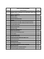
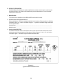
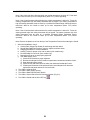
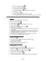
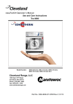
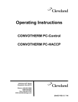
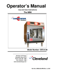
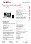
Installation Manual Installation and Maintenance Instructions CONVOTHERM BY CLEVELAND COMBI ELECTRIC MODELS 1333 East 179th Street Cleveland, Ohio 44110 Phone: (216) 481-4900 Fax: (216) 481 3782 www.clevelandrange.com Part No. COMBI-OE-INM REV. A, 8/05 FOR THE INSTALLER FOR YOUR SAFETY Do not store or use gasoline or other flammable vapors or liquids in the vicinity of this or any other appliance. WARNING WARNING Improper installation, adjustment, alteration, service, or maintenance can cause property damage, injury or death. Read the installation, operating and maintenance instructions thoroughly before installing or servicing this equipment. Disconnect power before servicing. ALL SERVICE MUST BE PERFORMED BY A QUALIFIED CLEVELAND RANGE AUTHORIZED TECHNICIAN. WARNING Do not connect Combi steamer-oven drain connection to any drain material that cannot sustain 140o Fahrenheit. This Installation Manual is a part of your new Convotherm by Cleveland combination oven steamer. You must keep and maintain it for the entire life span of your Combi and pass it on to the next owner of the unit. RETAIN THIS MANUAL FOR REFERENCE KEEP IT WHERE YOU CAN USE IT This manual may be subject to new technical developments, modifications, and unforeseen errors. DO NOT OPERATE OR ATTEMPT TO OPERATE THIS APPLIANCE OR ANY ACCESSORIES WITHOUT READING COMPLETELY AND FULLY UNDERSTANDING THIS MANUAL Cleveland STATEMENT OF POLICIES LIMITED WARRANTY CLEVELAND RANGE products are warranted to the original purchaser to be free from defects in materials and workmanship under normal use and service for the standard warranty period of one year from date of installation or 18 months from date of shipment, which ever comes first. CLEVELAND RANGE agrees to repair or replace, at its option, f.o.b. factory, any part which proves to be defective due to defects in material or workmanship during the warranty period, providing the equipment has been unaltered, and has been PROPERLY INSTALLED, MAINTAINED, AND OPERATED IN ACCORDANCE WITH THE CLEVELAND RANGE OWNER’S MANUAL. CLEVELAND RANGE agrees to pay any FACTORY AUTHORIZED EQUIPMENT SERVICE AGENCY (within the continental United States, and Hawaii) for reasonable labor required to repair or replace, at our option, f.o.b. factory, any part which proves to be defective due to defects in material or workmanship, during the labor warranty period. This warranty includes travel time not to exceed two hours and mileage not to exceed 50 miles (100 miles round-trip), BUT DOES NOT INCLUDE POST STARTUP, TIGHTENING LOOSE FITTINGS, MINOR ADJUSTMENTS, MAINTENANCE, CLEANING OR DESCALING. The standard labor warranty allows factory payment of reasonable labor required to repair or replace such defective parts. Cleveland Range will not reimburse the expense of labor required for the repair or replacement of parts after the standard warranty period, unless an Extended Labor Warranty Contract has been purchased to cover the equipment for the balance of the warranty period from the date of equipment installation, start-up, or demonstration. PROPER INSTALLATION IS THE RESPONSIBILITY OF THE DEALER, THE OWNER-USER, OR INSTALLING CONTRACTOR, AND IS NOT COVERED BY THIS WARRANTY. Many local codes exist, and it is the responsibility of the owner and installer to comply with these codes. Cleveland Range equipment is built to comply with applicable standards for manufacturers, including UL, ANSI, NSF, ASME/Ntl. Bd., CSA, and others. BOILER (Steam Generator) MAINTENANCE IS THE RESPONSIBILITY OF THE OWNER-USER AND IS NOT COVERED BY THIS WARRANTY. The use of good quality feed water is the responsibility of the Owner-User (see Water Quality Recommendations below). THE USE OF POOR QUALITY FEED WATER WILL VOID EQUIPMENT WARRANTIES. Boiler maintenance supplies, including boiler hand hole gaskets, are not warranted beyond the first 90 days after the date the equipment is placed into service. Preventive maintenance records must be available showing descaling per applicable Cleveland Operator Manual for Boiler Proration Program considerations. WATER QUALITY RECOMMENDATIONS TOTAL DISSOLVED SOLIDS TOTAL ALKALINITY SILICA CHLORIDE pH FACTOR less than 60 parts per million less than 20 parts per million less than 13 parts per million less than 30 parts per million greater than 7.5 The foregoing shall constitute the sole and exclusive remedy of original purchaser and the full liability of Cleveland Range for any breach of warranty. THE FOREGOING IS EXCLUSIVE AND IN LIEU OF ALL OTHER WARRANTIES, WHETHER WRITTEN, ORAL, OR IMPLIED, INCLUDING ANY WARRANTY OF PERFORMANCE, MERCHANTABILITY, OR FITNESS FOR PURPOSE, AND SUPERSEDES AND EXCLUDES ANY ORAL WARRANTIES OR REPRESENTATIONS, OR WRITTEN WARRANTIES OR REPRESENTATIONS, NOT EXPRESSLY DESIGNATED IN WRITING AS A “WARRANTY” OR “GUARANTEE” OF CLEVELAND RANGE MADE OR IMPLIED IN ANY MANUAL, LITERATURE, ADVERTISING BROCHURE OR OTHER MATERIALS. CLEVELAND RANGE’S liability on any claim of any kind, including negligence, with respect to the goods or services covered hereunder, shall in no case exceed the price of the goods or services, or part thereof, which gives rise to the claim. IN NO EVENT SHALL CLEVELAND RANGE BE LIABLE FOR SPECIAL, INCIDENTAL, OR CONSEQUENTIAL DAMAGES, OR ANY DAMAGES IN THE NATURE OF PENALTIES. Free Start-Up Program Get the most from your Cleveland Range equipment with Cleveland Range’s “Free Start-Up.” Performance Check-Out: Contact your Cleveland Range maintenance and repair center for your Performance Check-Out before starting your new Convotherm by Cleveland Combination Oven-Steamer. The Performance CheckOut includes: inspection of installation, review of cleaning and maintenance instructions, and start of warranty protection. Equipment Demonstration: After your Performance Check-Out, contact your Cleveland Range sales representative for your free demonstration of proper operation, optimal use, and correct care of your new equipment. Use and Care Video: After your Equipment Demonstration, your sales representative will present and explain your free copy of the Cleveland Range Use and Care Video. (Combi video release expected in September 2005.) Consult your Customer Service Directory or call Cleveland Range at 216-4814900 to begin your free Start-Up Program. Your “Combi” in Action You can cook a variety of foods in your Convotherm by Cleveland Combination Oven-Steamer, or “Combi,” using hot air, steam, and Combi hot air and superheated steam. Your Combi is extremely versatile and can cook sous-vide as well as steam, blanch, poach, stew, boil, roast, braise, bake, grill, “fry,” gratinate, rethermalize and defrost. Just place food in containers or on wire racks, select the cooking program, and time, or core temperature and start cooking with your Combi. NOTICE: Cleveland Range CONVOTHERM by Cleveland Combi Oven-Steamers (Combis) are intended for commercial use only. NOTICE: The ambient temperature must be between 40°F and 95°F. INSTALLATION AND MAINTENANCE Chapter 1 2 3 4 5 Table of Contents Page GENERAL INFORMATION ABOUT CONVOTHERM BY CLEVELAND 1 GENERAL SAFETY GUIDELINES FOR INSTALLERS, USERS, AND SERVICE TECHNICIANS 1 PRODUCT INFORMATION 2 PRODUCT VIEWS 3 CONTROL PANELS 4 INSTALLATION INSTRUCTIONS 6 GENERAL 6 INSTALLATION OF THE COMBI – Overview and General Instructions 7 INSTALLATION OF THE COMBI – Selecting a Location for the Combi 8 UTILITIES CONNECTIONS 9 Install Electric Power Lines 9 Electrical Connection Data 10 Install Water Supply 11 Install Free Air Vented Drain Lines 14 Exhaust Hood Requirements 16 Moving a Combi to its Operating Location 17 For ALL Combis 18 For Stand Mounted Combis 18 CHECKOUT and STARTUP 20 STARTUP PROCEDURE AND OPERATIONAL TESTS 21 STARTUP PROCEDURE 22 SET CONTROL PANEL OPTIONS 22 TROUBLESHOOTING 28 Error Messages and Remedies 29 These operating irregularities do not have error messages 31 Emergency Operation 32 Operating Instructions for Emergency Operation 32 The Combi will operate if these errors occur 33 CHAPTER 1 GENERAL INFORMATION ABOUT CONVOTHERM BY CLEVELAND A. GENERAL SAFETY GUIDELINES FOR INSTALLERS, USERS, AND SERVICE TECHNICIANS 1. Read, understand, and follow the instructions, and heed and obey the warnings of the Installation Manual, the Operator’s Manual, and the labels on the Combi, accessories, and supporting products. 2. Improper installation, maintenance, cleaning, or modifications to the Combi can lead to injury or death of the operator(s), and equipment and property damage. 3. STEAM – To avoid steam burns, open the Combi door by turning the handle to the horizontal (“airing”) position and waiting for the steam and condensate to clear. Then stand back and to the hinge side of the door and slowly open the door. Never breathe steam, superheated steam, or hot air. Note: The cooking program is interrupted whenever the door is opened. 4. HEAT – The Combi, cooking containers, shelves, and inner door and anything else inside the cooking compartment are HOT, as are many of the component parts. Wear DRY heatproof gloves or mitts. 5. EXHAUST VENTS – The top of the Combi, and the gas and steam exhaust vents are very hot during operation and remain hot for some time. Never breathe gas or steam from the exhaust vents. Use extreme caution when working on or near this area and component parts. 6. SCALDS – Do not place containers with liquid contents or contents that become liquid on oven racks higher than you can see into the containers. Cover containers (individual or on trolleys) containing hot or hot liquid items to help prevent spills during transport. Observe and heed and obey and obey the additional warnings and warning labels posted on the Combi 7. GREASE SPATTER – Hot grease will spatter and cause burns if sprayed with water. Locate fryers and similar appliances outside the range of the Combi hand shower. 8. ELECTRIC SHOCK – Use the hand shower only on the inside of the oven. Use of the hand shower, hoses, power cleaners, or pressure washers on the outside of the Combi can cause electric shock and / or damage electrical and electronic components. 9. CLEANING AND DAILY MAINTENANCE – Wait for the Combi to cool before cleaning and performing daily maintenance. Do NOT spray water in a hot cooking compartment. Do not use hoses, power cleaners or pressure washers, or harsh or abrasive cleaning agents inside OR outside the cooking compartment. 10. CLEANING AGENTS – Use only Convotherm by Cleveland cleaning and descaling products. Follow the instructions and heed and obey the warnings on the labels. Other products can damage the Combi, cause injury, or present heath hazards. 11. Wear BOOTS appropriate to the work area to help protect feet, and to help prevent slips and falls. 12. Use non-slip, draining, anti-fatigue FLOOR MATS (not included) rated for use in wet, greasy, and dry work areas to help prevent slipping and / or falling injuries. Obtain the best mats for your needs from your local supplier. 1 B. PRODUCT INFORMATION Cleveland Range, LLC assigns two product identification numbers to each Combi: a model number and a serial number. The model number identifies the product characteristics. The serial number identifies the individual unit. 1. Model Number This manual covers installation of the OEB and OES model electric Combis. 2. Serial Number and Equipment Record During manufacture, Combis are assigned individual serial numbers. Please provide the following information when you contact Cleveland Range or a qualified Cleveland Range authorized service representative: Serial Number________________________________________________________________ Model Number________________________________________________________________ 3. Product Information Plate The Product Information Plate on the left side of the unit lists the model and serial number as well as the power and wiring requirements of the steamer. Refer to Figures 1-2 and 1-3 for the location of the plate. Figure 1-1 illustrates a typical Product Information Plate. Figure 1-1 Typical Product Information Plate 2 WARNING C. PRODUCT VIEWS Figures 1-2 and 1-3 Anything in the path of the door will be crushed. 1. Control Panel KEEP HANDS CLEAR! 2. Disappearing Door with Double Glass Panel 3. Door Handle • Vertical: closed. CAUTION • Horizontal: open. HOT! • To open the Combi door: turn the handle to the horizontal (airing) position. 6 7 4. Combi Supports Adjustable height legs. (6” minimum.) 5 2 5. Hand Shower Adjustable flow. 1 Convenient hanger. 13 6. Shut-off Valve 3 12 Close when Hand Shower is not in use. 7. Low-Pressure Failsafe Device 8. Infeed Assist Mechanism (floor models) 10 9 11 4 9. Rating Plate Oven stand: • Contains the following information: Always set up • Power Consumption. tabletop • Voltage. appliances on • Number of Phases. an oven stand • Frequency. or work table • Model Number. (minimum • Serial Number. CAUTION height 24.4”). 10. Side Wall 6 HOT! • Removable for service by qualified 5 Cleveland Range authorized service 7 representatives. • Disconnect power before servicing. 2 • Electrical Diagrams located on the inside of 1 the Side Wall. 3 11. Door Drip Tray (behind door) Built-in, self-emptying. (Not available on 12.20, 20.10, or 20.20.) 13 12. Door Switch 13. Oven Light 12 9 10 8 4 3 D. Figure 1-4 Control Panel Control Panel ON/OFF (1) • When Combi is turned ON: • Self-diagnosis is performed. • Oven light comes on. • Steam generator fills and heats (OEB and OGB models). “Steam” cooking mode (2) • Oven temperature is continuously variable between 86°F and 248°F. “Combi Hot Air and Superheated Steam” cooking mode (3) • Oven temperature is continuously variable between 212°F and 482°F. “Hot Air” cooking mode (4) • Oven temperature is continuously variable between 86°F and 482°F. “Retherm” cooking mode (5) • Oven temperature is continuously variable between 248°F and 320°F. Start/Stop (6) • Start cooking modes, cooking ideas, and recipes from the Cookbook. • Stop: • Stops the cooking activity. • Signal Tone sounds confirming interruption of cooking activity. • Escape or Exit Smart Key functions. Cookbook (7) • Call-up or Exit cookbook. • View a list of stored recipes in the display. Smart Key (8) • Set extra functions. • Set-up the Combi. • Enter Sub-Menus. Write/Edit (9) • Create, change, copy, and delete recipes. 4 Function and Operation Icons (10-16) • Core Temperature (20) Icons light when function or activity is engaged: Reduced Power (10) (optional feature for ELECTRIC models OEB & OES). • Set the nominal core temperature. • See the actual or nominal core temperature. Burner or Electric Heating ON (11). • See the actual core temperature during cooking in time mode. Paging / Scrolling to left or right (21/22). Reduced Fan Speed (12 ). Cooking Mode Engaged (13). Key Lock (14). Crisp & Tasty (demoisturizing) Engaged (15). • Program Protection (16). D 6019002_00 Set: Display in normal mode: • Oven temperature. • Date. • Cooking time. • Time. • Core temperature. • Oven Temperature. • Program name. • Cooking Time. • Program number. • • Core Probe Temperature. • Selector Dial (23) • Display (17) • Page / Scroll one step forwards or back in programming mode. Display in programming mode: Select Smart Key functions and editing functions as well as recipes in the Cookbook. • Clear text. Press & Go (symbol) (24) • Memory. • Start saved recipes with one key. • LED below key lights up when corresponding recipe is started. • Symbols. Oven Temperature (18) • Set the nominal oven temperature. • View the actual or nominal oven temperature. Notes: Magnetic door switch If the oven door is opened during a program, the magnetic door switch automatically interrupts the cooking program. The timer stops. After closing the oven door, the Combi automatically continues the cooking program. If the oven door is opened when the Signal Tone sounds at the end of a program, the Signal Tone will stop. Cooking Time (19) • Set the cooking time from 1 min to 9 hrs 59 min. • Set Continuous Mode 1. At 9:59 or 0:01, release the Selector Dial. 2. Turn the Selector Dial again to the left or right. • See the actual or nominal cooking time. • Pre-set start time. • See elapsed cooking time when using Core Temperature mode. • 5 Operate controls with hands only! CHAPTER 2 INSTALLATION INSTRUCTIONS A. GENERAL This equipment should be installed only by qualified, professional plumbers, pipe fitters, and electricians. 1. The installation of this Combi must conform with: a. The Basic Plumbing Code of the Building Officials and Code Administrators International, Inc. (BOCA). b. The National Electrical Code, ANSI/NFPA 70 (latest edition), or the Canadian Electrical Code, CSA C22.2 as applicable. c. The Food Service Sanitation Manual of the Food and Drug Administration (FDA). d. All applicable national, state, and local laws, codes, and regulations. 2. Installation instructions must be read in their entirety before starting installation of a Combi. DANGER DEATH, INJURY, AND EQUIPMENT DAMAGE will result from the improper installation, adjustment, alteration, service, or maintenance of a Combi, or installation of a Combi damaged during shipment or storage. Also, any of these actions void the warranty. DO NOT install a damaged Combi. INSTALL the Combi according to the policies and procedures outlined in this manual. 3. Inspect the Combi for shipping damage. a. Check carton and packing for shipping damage. b. Note any damage on the shipping paperwork as soon as the carton arrives. c. Unpack the Combi and check for shipping damage. d. If the Combi is damaged or damage is suspected: 1) Inform your dealer at once. 2) Inform Cleveland Range in writing within 3 days. 3) Submit a Damage Claim to the shipper. 4. General Safety a. The Combi must be used only to cook food b. Do not cook or reheat products in packages not specifically designed for this purpose. c. Read, understand, and follow the instructions and heed and obey the warnings of the Installation Manual and Operator’s Manual. d. Read, understand, and follow the instructions and heed and obey the warnings of the labels on the Combi, accessories, and supporting products. e. NEVER install or operate a damaged Combi. f. Observe all local regulations, requirements, and standards. 6 B. INSTALLATION OF THE COMBI – Overview and General Instructions DANGER DEATH, INJURY, AND EQUIPMENT DAMAGE will result from improper lifting. Use enough workers with training and experience lifting heavy equipment to place the Combi on the supporting surface 1. 2. 3. 4. 5. Select the Combi’s operating location. Complete the drain, electric, and water lines before positioning and leveling the Combi. Position and level the Combi. Connect the utility lines after positioning and leveling the Combi. After Setup and Checkout, the Combi should provide years of reliable operation. WARNING All clearance requirements above, below, and around the Combi are the same for noncombustible locations as for combustible locations. CAUTION Malfunctions and equipment damage will result from improper installation. Malfunctions and/or damage resulting from improper installation are NOT covered by warranty. Glass damage resulting from improper use or cleaning is NOT covered by warranty. Damage from improper use or cleaning, repair, maintenance, descaling, and failure to use appropriate cleaning solutions is NOT covered by warranty. Light bulbs, sealants, and consumable supplies in normal use are NOT covered by warranty DANGER A COMBI MUST BE LEVEL BOTH FRONT TO BACK AND SIDE TO SIDE IN ALL INSTALLATIONS. OPERATING A COMBI OUT OF LEVEL WILL CAUSE CATASTROPHIC DAMAGE. 7 C. INSTALLATION OF THE COMBI 1. Selecting a Location for the Combi a. For safe and efficient operation, observe the following criteria when selecting an operating location for a Combi 1) Passages and doors must be high enough and wide enough for a Combi and its pallet. See Table 2-1. 2) Location selected must be capable of supporting a Combi. See Table 2-1. 3) The area MUST be free from and clear of combustible materials. 4) KEEP THE COMBI AREA FREE AND CLEAR OF COMBUSTIBLES. 5) The operating surface must be level enough to allow leveling a Combi with its adjustable legs. 6) A Combi MUST be level both front to back and side to side. 7) Position the Combi so it will not tip or slide. 8) The floor where the loading trolley rolls must be level and even. 9) Level the floor if needed. (Fig. 7). 10) The ambient temperature should be within 40° and 95° F. 11) Proper air supply for combustion and ventilation is REQUIRED for and CRITICAL to safe, efficient operation of a Combi. 12) Required Clearances: Rear - 2", Left Side - 4". Right Side 2 1/2" a) Allow for sufficient distance if a "high heat source" (i.e. Broiler) is located next to the unit b) Allow for sufficient clearance on left side for service access (contact the factory service department for recommendations) c) Installation must comply with all local fire and health codes. 13) Do not install the Combi directly over a drain. Steam rising up out of the drain will adversely affect operation, hamper cooling air circulation, and damage electrical and electronic components. 14) Make sure the air vents of the Combi are not blocked. TABLE 2-1 WEIGHTS AND DIMENSIONS INCLUDING PALLET AND CRATE STEAM GENERATOR MODEL OEB-6.10 OEB-6.20 OEB-10.10 OEB-10.20 OEB-12.20 OEB-20.10 OEB-20.20 INJECTOR MODEL OES-6.10 OES-6.20 OES-10.10 OES-10.20 OES-12.20 OES-20.10 OES-20.20 WEIGHT WIDTH DEPTH IN IN IN POUNDS INCHES INCHES 375 38 36 485 47 45 475 38 37 540 47 45 717* 48 46 750* 40 38 970* 52 46 * = including Loading Trolley 8 HEIGHT IN INCHES 40 42 50 50 64 85 85 D. UTILITIES CONNECTIONS FOR THE INSTALLATION OF THE COMBI 1. Install Electric Power Lines The electrical supply must match all electrical and wiring requirements specified on the rating plate and must be made in accordance with the following requirements: a. The Combi must be properly grounded and have the electrical power lines installed in accordance with: 1) The National Electric Code, ANSI/NFPA No. 70 LATEST EDITION (USA). 2) Canadian Electrical Code, CSA C22.2. 3) Any other applicable national, state, or local laws, codes, and regulations. b. Check the rating plate to make sure the Combi is compatible with the local electric supply. c. Note: the rating plate is located on the left side of the Combi. d. Install a dedicated main disconnect switch and a separate fuse or breaker (per code) for each Combi. The fused or breakered disconnect switch is referred to as the “main external power switch.” (Fig. 9). e. The main terminals are behind the removable left side cover in the service connection area. f. The wiring diagram and the spare parts list are in the service connection area. g. Check all cable and wire connections for size, location, and tightness before starting a Combi. h. The Combi must be electrically grounded by the installer. MAIN EXTERNAL POWER SWITCH COMBI DRAIN LINE COLD WATER SUPPLY LINES Figure 9 Main External Power Switch 9 2. Electrical Connection Data Volts Phase Hz Amps Wires Wire Size, Cu, 90°C AWG Volts Phase Hz Amps Wires Wire Size, Cu, 90°C AWG Volts Phase Hz Amps Wires Wire Size, Cu, 90°C AWG Volts Phase Hz Amps Wires Wire Size, Cu, 90°C AWG Volts Phase Hz Amps Wires Wire Size, Cu, 90°C AWG Volts Phase Hz Amps Wires Wire Size, Cu, 90°C AWG OEB & OES 6.10 208 3 60 27.3 3 + Ground 240 3 60 30.8 3 + Ground 12 10 OEB & OES 6.20 AND 10.10 208 3 240 3 60 45.5 3 + Ground 60 51.8 3 + Ground 6 6 OEB & OES 10.20 AND 12.20 208 3 60 77.3 3 + Ground 240 3 60 88.3 3 + Ground 3 2 OEB & OES 20.10 208 3 60 91 3 + Ground 240 3 60 103.6 3 + Ground 2 2 OEB & OES 20.20 208 3 60 149.9 3 + Ground 240 3 60 171.9 3 + Ground 2/0 3/0 OEB & OES 20.20 440 3 60 84 3 + Ground 480 3 60 91 3 + Ground 3 2 Minimum wire gauge required for field connection Attention: always observe local ordinances! 10 3. Install Water Supply a. b. c. d. Install the water supply before positioning the Combi. Water supply line(s) must be designed so the Combi can be moved for service. Construct all supply lines up to the point of installing the Combi. Flush the water supply lines before connecting the Combi to the water supply lines. e. Water Supply Requirements CAUTION Using water outside the limits specified in this manual without appropriate adjustment in the maintenance schedule voids warranty coverage. 1) Water Quality a. b. c. d. e. Check the quality of supply water (described below) before designing the water supply. Contact a local water treatment specialist for on-premises water analysis. Minimum feed water quality requirements are listed in Table 2-3. Poor water supply quality degrades Combi performance. Softened or chlorinated water damages the steam generator by increasing corrosion. Carbon type filters are required before water enters the steam generator if supply water is softened or chlorinated. f. If a water treatment system must be installed to achieve acceptable water quality, install it BEFORE connecting the water supply lines to a Combi. g. If analysis shows that supply water is below Minimum Water Quality: 1) EITHER a water treatment system and/or carbon filter must be installed in the line feeding the steam generator, 2) OR the frequency of maintenance, cleaning, and descaling must be increased beyond that recommended in the maintenance schedule. 3) Contact your Cleveland Range sales representative for details on how to provide water per Minimum Water Quality in Table 2-3, or how to increase the frequency of maintenance, cleaning, and descaling. Table 2-3 Minimum Water Quality Requirements Scale Forming Factors Total Dissolved Solids Silica Alkalinity Concentrations must be: less than 60 parts per million less than 13 parts per million less than 20 parts per million Corrosion-Causing Factors Free Chlorine Chloride pH factor Concentrations must be: less than 0.5 parts per million less than 30 parts per million greater than 7.5 11 2) Water Supply System Pressure Requirements The water supply must provide: • A minimum dynamic pressure of 35 psi (2.4 kg/cm2) • A maximum static pressure of 60 psi (4.1 kg/cm2). a. Install Water Supply Lines The Installer/Owner is responsible for the correct water connection of the Combi. When connecting water supply lines observe the following instructions, and any and all other applicable national, state, and local codes and regulations: 1) Connect the Combi to COLD WATER 2) Never connect the Combi to HOT WATER! The Condenser system and the steam generator will not work properly if connected to HOT or WARM water. 3) The water supply must have a minimum dynamic (flow) pressure of 35 psi (2.4 kg/cm²) and a maximum static pressure of 60-psi (4.1 kg/cm²). 4) If the static pressure is above 60 psi, a pressure regulator must be used and set at approximately 50 psi. Pressure above 60 psi can damage solenoid valves. 5) Combis are supplied with two connection points for incoming water: condenser, and generator or spritzer. 6) If water supply meets requirements shown in Table 2-3 then the Single Water Supply Arrangement shown in Figure 2-10 may be used. a) If the Single Water Supply arrangement is used: Supply piping to the Water Distributor (cold water supply splitter) (Order Number SPN), or similar tee fitting must be at least next largest size of pipe than the connection provided at the Combi. 7) If water supply fails to meet requirements shown in table 2-3 then use Separate Feed Water Supply Arrangement shown in figure 2-11. 8) Installation Requirements: a) Apply non-hardening pipe sealant to all the threaded connections except the ¾” GHT Female (Garden Hose Thread or National Hose Thread) connections at the Water Connection. GHT or NHT connections do not require pipe sealant. b) Install a manual water shut-off valve (not provided) between main cold water supply line(s) and Combi supply lines. c) The National Sanitation Foundation (NSF) requires installation of a check-valve (or other approved anti-backflow / anti-siphon device) (not provided) in all supply lines in accordance with and as required by local, state, and national health, sanitation and plumbing codes. d) Consult local codes to determine exactly what type of anti-backflow / anti-siphon device is necessary to meet local requirements. b. Testing Water Supply Lines 1) Check all connections for proper tightness. 2) Remove side panels to inspect water connections inside the Combi. 3) Open the water supply valves. 4) Check all lines and connections for leaks, both inside and outside the Combi. 5) If Startup and Checkout will be performed next, leave side panel off; otherwise, replace the side panel and secure it to the Combi. 12 COMBI Water Connection Air/Water Column (if required) Condenser Solenoid Steam Generator or Injector, Dehumidification, Cleaning System Main Cold Water Supply Water Connection Pressure Reducer (if required) Main Water Shut Off Valve Figure 2-10 Cleveland Range Single Water Supply Arrangement Water Connection Air/Water Column (if required) COMBI Cold Tap Water Supply Condenser Solenoid Steam Generator or Injector, Dehumidification, Cleaning System Pressure Reducer (if required) Water Connection Main Water Shut Off Valve Conditioned* Cold Water Supply Figure 2-11 Cleveland Range Separate Water Supply Arrangement * “Conditioned” indicates water that has been filtered or treated by a Cleveland Range approved method to meet or exceed the water quality standards of Table 2-3 13 DANGER DEATH, INJURY, EQUIPMENT and PROPERTY DAMAGE will result from improper installation of drain outlet lines. The following restrictions and requirements are critical to the safety of personnel and equipment, and must not be violated under any circumstances: • Do not connect the Combi drain connection to any drain material that cannot sustain 140o F. • Do not connect drains from any other equipment to the drain line of the Combi. • Do not connect the drain outlet extension line directly into a floor drain or a sewer line. • The drain line must be free air vented, have gravity flow from the Combi, and terminate outside the perimeter of the Combi. • Improper installation of drain outlet lines voids the Combi warranty. 4. Install Free Air Vented Drain Lines Furnishing and installing drain lines is the responsibility of the Owner/Installer. a. The drain lines must be installed in compliance with the Basic Plumbing Code of the Building Officials and Code Administrators International, Inc. (BOCA), and the Food Service Sanitation Manual of the Food and Drug Administration (FDA) and any other applicable national, state, or local codes and regulations. b. Do not install the Combi directly over a drain. Steam rising up out of the drain will adversely affect operation, hamper cooling air circulation, and damage electrical and electronic components. c. The total length of pipe and number of bend fittings required to reach the open drain determines the pipe size used to extend the drain line to an open drain. 1) If the drain outlet extension requires 6 feet or less of pipe, and no more than two elbows are required, 2 inch pipe and fittings are acceptable. 2) If the drain outlet extension requires 6 to 12 feet of pipe, or requires three elbows, then 2½ inch pipe and fittings are required. 3) The drain line must have gravity flow from the Combi drain outlet to floor drain. 4) Do not install a trap in the drain line. d. Free air venting requires minimum 1” clearance between the end of the drain line and the top of the floor drain. e. Do not connect the Combi drain directly to drains or to the plumbing of any other equipment f. Refer to Figure 2-12: Run (do not connect) the Combi drain from the Combi as described below: 1) Use Drain Kit, Cleveland Range Part No. C3416730. See Figure 2-12 A 2) Cut the 2” (50 mm) tubing to length. 3) Run the 2” tubing of appropriate type to the drain outlet. 4) Leave a minimum 1” clearance between the end of the drain line and the top of the floor drain. 14 Figure 2-12 Typical Drain Layout Figure 2-12 A NUMBER, DESCRIPTION, AND PART NUMBER 1 GASKET, INTERNAL, DRAIN TO ELBOW, P/N C6015406 2 ELBOW, 87°, P/N C6015402 3 PIPE, BELL END, 50mm x 500mm (2” x 19.685”), P/N C6015403 4 ELBOW, DRAIN CONNECTION, P/N C6015405 5 GASKET, EXTERNAL, ELBOW TO DRAIN PIPE, P/N C6015243 15 5. Exhaust Hood Requirements a. Installation under an exhaust hood may be required. Check local requirements before installing a Combi or any other food service equipment. b. The exhaust hood must extend over the exhaust ports and meet the following requirements: 1) The Exhaust hood must be sized for the cumulative ventilation requirements of all the appliances in the area under the hood, including the Combi. 2) If an existing hood cannot be used, a new one must be constructed over the Combi. 3) When determining hood size be sure to include Operating Clearances of 2 inches rear, 24 inches control side, and 2 ½ inches door side. Model Number, Height, Depth, and Width in inches for calculating hood dimensions and ventilation capacity requirements. OEB-6.10 OEB-6.20 OEB-10.10 OEB 10.20 OEB-12.20 OEB-20.10 OEB-20.20 OES-6.10 OES-6.20 OES-10.10 OES-10.20 OES-12.20 OES-20.10 OES-20.20 Height 34’’ 36” 44” 44” 56” 77” 77” Depth 32” 41” 32” 41” 42” 34” 42” Width 37” 48” 37” 48” 49” 38” 49” Model 16 6. Moving a Combi to its Operating Location 1 Figure 1 a. Transport the Combi on a pallet. b. Keep the Combi UPRIGHT. c. The packing list is under the top of the packing carton (1 on Fig. 1). d. Remove all cartons, packing material, documents, shelves, loading trolley, etc. from the oven chamber. e. Remove the Combi from the pallet. 1) Note the weight of the units in Table 2-1. 2) Be sure the lifting forks of a forklift or low lift truck are in the correct position before picking up the Combi. See Figure 2 and Figure 3. 3) To lift units with a forklift, low lift truck, or hand truck: place wooden spacers between the feet of the Combi (Fig. 3). 4) Stay to the right of the Drain (A) and the Overflow (B) on Figure 3. See Table 2-2. 5) Keep the unit level! Do not tip! 2 Figure 2 3 Figure 3 B A BOARDS A B TABLE 2-2 B AND A FROM HAND SHOWER SIDE STEAM GENERATOR MODEL INJECTOR MODEL DIMENSION B FROM HAND SHOWER SIDE IN INCHES DIMENSION A FROM HAND SHOWER SIDE IN INCHES OEB-6.10 OES-6.10 13 5/16 11 1/4 OEB-6.20 OES-6.20 14 3/4 12 3/4 OEB-10.10 OES-10.10 13 5/16 11 1/4 OEB-10.20 OES-10.20 14 3/4 12 3/4 OEB-12.20 OES-12.20 14 3/4 12 3/4 OEB-20.10 OES-20.10 13 5/16 11 1/4 OEB-20.20 OES-20.20 14 3/4 12 3/4 17 7. For ALL Combis WARNING Out-of-level Combis can TIP OVER! Do not operate, or attempt to operate an out-of-level Combi: Tipping over and/or other catastrophic failure can result. Combis must be level front-to-back and side-to-side. Operating an out-of-level Combi voids the Warranty. a. b. c. d. Keep the vents on the bottom and top of the Combi clear, clean, and free of obstruction. The floor where the loading trolley rolls must be level and even. Level the floor if needed. (Fig. 5). Level the Combi from the bottom: Use the height adjustable legs of the Combi and a level to so the Combi is level front-to-back and side-to-side (Fig. 4). e. The trolley must stand level in the Combi. f. A roll-in ramp, (not provided), may be used. Maximum angle of the roll-in ramp is 4 degrees (Fig. 6). g. If there is a drain grid in front of the Combi, place or affix flat material on the drain grid so the trolley can roll smoothly over it (Fig. 5). h. Do not store anything on top of a Combi. i. Required Clearances: Rear - 2", Left Side - 4". Right Side 2 1/2" a) Allow for sufficient distance if a "high heat source" (i.e. Broiler) is located next to the unit b) Allow for sufficient clearance on left side for service access (contact the factory service department for recommendations) c) Installation must comply with all local fire and health codes. j. Keep the vents on the top and bottom of the Combi clear, clean, and free of obstruction. 8. For Stand Mounted, Stacked, and Caster Equipped Combis a. Follow the separate instructions included with the Stand, Stacking Kit, or Caster Kit. b. Use only genuine Convotherm by Cleveland Stacking Kits, Caster Kits, and replacement parts. c. Use of Stands, Stacking Kits, Caster Kits, and replacement parts other than genuine Convotherm by Cleveland Stands, Stacking Kits, and Caster Kits can result in injury and / or catastrophic equipment failure. d. Use of Stands, Stacking Kits, Caster Kits, and replacement parts other than genuine Convotherm by Cleveland Stands, Stacking Kits, and Caster Kits will void the Warranty. 18 Figure 4 7 Figure 5 Figure 6 19 9. CHECKOUT and STARTUP The Checkout and Startup procedure prepares a recently installed or repaired Combi for operation. The procedures check proper electrical, gas, water, and drain connections to the Combi, and verify basic Combi operation. Table 2-5 Installation Check List TASK REFERENCE Page No. Preparation Check operating location clearances. Test supply water quality. Verify Exhaust Hood Requirements. Verify Electric Power Requirements. Installation Check electrical line connection Check water supply connection Leak Test water supply lines Verify Combi is level Check drain line connection Check Exhaust Hood Perform Startup Test 16,17 11 16 10 9 11 11 18,19 14 16 21 Notes: 20 COMPLETED CHAPTER 3 STARTUP PROCEDURE AND OPERATIONAL TESTS DANGER Death, severe electrical shock, or equipment damage can result from touching any component inside a Combi when the main external power switch is in the ON position. Use extreme caution during testing with the access cover removed. WARNING When checking inside the Combi: always open the door slowly and stand to the hinge side and away from the Combi. WARNING Water leaking from the door gasket can be a sign of a blocked drain. If the drain is blocked, hot water can accumulate inside the compartment and spill out when the door is opened. DANGER Do NOT attempt to operate a Combi during a power failure! In the event of a power failure: turn OFF the Main External Power Switch and the Control Power Service Disconnect Switch. If the power failure is prolonged: turn OFF the water supplies. When power is restored: restart a Combi with the Startup Procedure. 21 A. STARTUP PROCEDURE Note: If the Combi has been delivered when the outside temperature is below 40° F then wait for the Combi to warm up to room temperature (about 72° F) before operating. Note: If the Combi has been delivered when the outside temperature is below 32° F then the cooking compartment high limit safety thermostat will be tripped. The cooking compartment high limit safety thermostat must be reset by a qualified Cleveland Range authorized service technician. Wait for the Combi to warm up to room temperature (about 72°F) before operating. Note: If the Combi has been delivered when the outside temperature is below 23° F then the steam generator high limit safety thermostat will be tripped. The steam generator high limit safety thermostat must be reset by a qualified Cleveland Range authorized service technician. Wait for the Combi to warm up to room temperature (about 72°F) before operating. Note: Remove the plastic cover from the tip of the Temperature Probe before starting the Combi. 1. After initial installation, check: a. Suction Plate (Hinged Fan Guard) for both swing and latch action. b. Hinged Removable Pan Racks for remove, replace, and latch action. c. Hanging Shelf Rack for correct installation. d. Loading Trolley for proper roll in and out action (floor models only). e. Pre-heat Bridge for correct fit (floor models only). f. Descaling port cap is on and properly tightened. g. Test Water Supply Lines 1) Check all connections for proper tightness. 2) Remove the side panel of the Combi to inspect water connections inside the Combi. 3) Open the water supply valves. 4) Check all lines and connections for leaks, both inside and outside the Combi. 5) If Startup and Checkout will be performed next, leave side panel off; otherwise, replace the side panel and secure it to the Combi. 2. Turn ON the exhaust hood. 3. Turn ON the water supply valve(s). 4. Turn ON the Main External Power Switch. 5. Turn ON the Control Panel Service Disconnect Switch (Fig. 6-2). 6. Turn ON the Combi with the ON / OFF key 22 . 7. SET CONTROL PANEL OPTIONS. a. Start Setup Procedure . 1) Press Smart Key D 2) Use the Selector Dial 6019002_00 to select Setup . . 3) Confirm: Press Smart Key 4) Answer “Yes” with Smart Key . b. Set Language 1) Start Setup Procedure (Above). 2) Select Language . 3) Confirm with Smart Key . D 4) Select desired language with the Selector Dial 5) Confirm with Smart Key c. 6019002_00 . . Set Signal Tone 1) Start Setup Procedure (Above). D 2) Select Signal Tone with the Selector Dial 6019002_00 . . 3) Confirm with Smart Key 4) Display will show available signal tones. D . 5) Select a signal tone with the Selector Dial 6) Pausing on a tone icon will cause it to sound. 7) Select a signal tone by pausing on it. 6019002_00 8) Confirm with Smart Key . d. Set Volume 1) Start Setup Procedure (Above). D 2) Select Volume (speaker and slider icon) with the Selector Dial 6019002_00 . . 3) Confirm with Smart Key 4) Display will show volume options and an alert tone will sound. D 5) Set Volume with the Selector Dial 6) Confirm with Smart Key 6019002_00 . . e. Set Time 1) Start Setup Procedure (Above). D 2) Select Time (clock icon) with the Selector Dial 3) Confirm with Smart Key 6019002_00 . . D . 4) Select time format desired with the Selector Dial (Left and Right Arrows) to switch between 5) Use the Paging / Scrolling keys hours and minutes. 6019002_00 D 6) Set the time with the Selector Dial 7) Confirm with Smart Key . 23 6019002_00 . f. Set Date 1) Start Setup Procedure (Above). D 2) Select Date with the Selector Dial 3) Confirm with Smart Key 6019002_00 . . D . 4) Select date format desired with the Selector Dial to switch between day, month, and year. 5) Use the Paging / Scrolling keys 6019002_00 D 6) Set the date with the Selector Dial 7) Confirm with Smart Key 6019002_00 . . g. Select Temperature in C or F 1) Start Setup Procedure (Above). D 2) Select with the Selector Dial 3) Confirm with Smart Key 6019002_00 . . D 4) Use the Selector Dial to select C or F. 6019002_00 5) Confirm with Smart Key . h. Network Address 1) (Required for use of PC Control, PC-HACCP, and Convotherm Service System.) 2) Start Setup Procedure (Above). D 3) Use the Selector Dial to select the Network Address 6019002_00 (three computers icon). . 4) Confirm with Smart Key 5) The current address will be displayed. D 6) Use the Selector Dial to select the desired network address (1-99). 6019002_00 7) Confirm with Smart Key i. . Program Protection 1) Compatible, connected energy optimization equipment is required to use this option. 2) Connecting the unit to an energy optimization unit during power peaks in the kitchen can cause the energy supply from the optimization unit to be interrupted during critical phases. 3) The program protection function automatically prevents program in progress from being interrupted. a) Use the energy optimization lock if cooking time is crucial to the quality of a dish, including sensitive foods, short cooking times, or the regeneration of plates. b) Individual steps in a recipe can be protected by the program protection function. The energy optimization can be set so that the energy optimization unit will not intervene during a critical phase but may during a less sensitive cooking step. 4) The energy optimization unit has no access to the Combi. Instead, it accesses other connected devices. 5) To set Program Protection a) Press Smart Key . b) Various options will appear in the display. D c) Use the Selector Dial 6019002_00 to select Program Protection 24 . d) Confirm by pressing Smart Key . . e) Confirm “Yes” with Smart Key appears. f) The Program Protection icon g) The display shows the nominal settings for the selected program, cooking plan, or recipe. h) Press the Start/Stop key. i) The Combi will start with Program Protection activated. j) The energy optimization unit cannot intervene during active operation of the Combi. B. TEST PROCEDURES 1. Function Test a) SELECT the Superheated Steam cooking program: b) Press the Combi mode key . c) Press the Temperature key . D d) Turn the Selector Dial e) Press the Time key 6019002_00 to set the temperature to 150°C / 302°F. . D f) Set the time (10 minutes) with the Selector Dial 6019002_00 . g) Press the Start / Stop key . h) The Program will start and the display will show the nominal oven temperature and time remaining. i) STEAM GENERATOR Models: The heating element for the oven heat exchanger and the heating element for the steam generator turn on, and the program runs. j) ALL MODELS: the program in step 1 will run. k) The Signal Tone will sound and program will end when set time has elapsed. l) Press the Start / Stop key or carefully open the door. 2. EMPTY and RINSE the Steam Generator: a. Press Smart Key . b. Use the Selector Dial to select “Manual steam generator rinse” . . c. Confirm with Smart Key d. Steam generator will rinse. e. Total time 8 – 12 minutes, depending on model. 3. RUN a Semi-Automatic Cleaning Cycle: a. Close the door. . b. Turn ON the Combi with the ON / OFF key c. Bypass (answer “No”) Automatic Steam Generator Rinse, if necessary. d. Press Smart Key . A variety of icons appear in the display. e. Select Cleaning (brush icon) with the Selector Dial D f. Confirm selection with Smart Key . . g. Answer prompt “Yes” with Smart Key h. The brush icon 6019002_00 . lights and the nominal values for the program are displayed. 25 i. j. k. Press Smart Key to start the cleaning cycle. Step 1 of 4 is Hot Air at 158°F (70°C) for 10 minutes. Signal Tone sounds and display prompts “CONVOCLEAN.” Open the door. (In ordinary use, the operator sprays CONVOClean oven cleaner into the oven.) l. Close the door. Do NOT press the Start / Stop key . The cleaning cycle starts step 2 of 4 automatically. m. Step 2 of 4 is Steam at 86°F (30°C) for 9 minutes. n. Signal Tone sounds. Open the door. (In ordinary use, the operator would clean behind the Suction Plate.) o. Close the door. Do NOT press the Start / Stop key . The cleaning cycle starts step 3 / 4 automatically. p. Step 3 of 4 is Steam at 86°F (30°C) for 1 minute. No action is required. q. Step 4 of 4 is Steam at 212°F (100°C) for 10 minutes. r. s. t. Signal Tone sounds. Turn OFF the unit with the ON / OFF key . (In ordinary use the operator would carefully open the door and rinse the Combi with the Hand Shower) Leave door open slightly 4. For CONVOClean System equipped Combis: a. The oven chamber must be cold before starting this process. b. Before starting, remove large pieces food or cooking residue from the oven chamber. This will help prevent the drain from becoming blocked. c. Check the level of CONVOTHERM by Cleveland oven cleaner and nozzle rinsing fluid. The containers must be full and the suction pipes must be located in the fluid. d. Press Smart Key . Various options will appear in the display. D e. Use the Selector Dial f. 6019002_00 to select “CONVOClean system” Confirm by pressing Smart Key . . g. Select the level of cleaning 1) light soiling 2) medium soiling 3) heavy soiling 4) heavy soiling with Shine+ D h. PRESS the Temperature key and select cleaning level with the Selector Dial . i. Press Smart Key j. The display reads “Food inside oven?” If the oven is empty then answer “No.” k. Confirm by pressing Smart Key l. The display reads “Start auto-cleaning?” Answer “Yes” or “No” as desired. m. Confirm by pressing Smart Key . . n. The program will start the CONVOClean system automatically. 1) 2) 3) 4) Check the supply of CONVOClean and CONVOCare. Make sure the connections are correct. Use only CONVOClean, CONVOClean forte, and CONVOCare for cleaning. Use only Cleveland Range Dissolve for descaling the steam generator. 26 6019002_00 . 5. TEST Temperature Probe: a. b. c. d. e. f. g. h. Remove plastic tip protector from probe. Replace probe in its hanger. Set Temperature to 350° F in any cooking mode. Set Probe Temperature to 210° F. Begin cooking program. Display shows set (nominal) temperature on the left and probe temperature on the right. Press Temperature to display the actual temperature. When the actual temperature reaches 210° F the Signal Tone sounds and the Combi turns off. 27 CHAPTER 4 TROUBLESHOOTING Convotherm by Cleveland Combi Oven-Steamers are equipped with an automatic error diagnosis system. If an error occurs, the system will display error codes and a description of the error. To continue operating, emergency operation is available (see below). The following tables will help troubleshoot if errors or malfunctions occur while a Combi OvenSteamer is operating. The tables show possible causes and their remedies. WARNING If the Burner or Electric Heating ON icon and the Cooking Mode Engaged are lit but the burner or electric heater does not start and the fan does icon not start then remove the Combi from service. Call your qualified Cleveland Range authorized service representative at once. WARNING If an error cannot be rectified with the aid of this list, contact your qualified Cleveland Range authorized service representative at once. 28 Error Messages and Remedies Error E01 E02 E03 Message on display Not enough water Possible cause Remedy Water tap closed Open water tap Solenoid valve dirt filter clogged Remove and clean filter Solenoid valve fault Call customer service Allow Combi to cool or continue Connection area temp. too Connection area ventilation fault, air cooking with lower temperature. high supply blocked Call customer service Fan malfunction Motor temperature monitor triggered, Call customer service external failsafe triggered Fan motor fault Call customer service E04 Connection area fan malfunction Auxiliary fan fault Call customer service E05 No gas Gas supply interrupted Open gas valve E11 / E21 Excess temp. in oven / oven Excess oven temperature sensor failure Oven sensor fault E13 / E23 Excess temp. of steam generator/steam gen. sensor Steam generator sensor fault failure Water tap closed Call customer service Call customer service Call customer service Open water tap Excess temperature in condenser via Connect Combi to cold water, hot water connection restart E15 / E25 Excess temp. of condenser / condenser sensor failure Solenoid valve dirt filter contaminated Remove and clean filter Solenoid valve fault Call customer service Condenser sensor fault Call customer service E22 Core temp. sensor fault Core temp. sensor fault Set cooking program with time, and call customer service E24 Bypass sensor failure Bypass sensor fault Call customer service E26 Steam generator safety Safety temp. limiter sensor fault in Call customer service temp. limiter sensor failure steam generator E27 Excess temp. steam generator heater Steam generator dirty Rinse steam generator E29 Ground connection of sensor Temperature sensor fault Call customer service E33 Steam generator heater error Steam generator heater fault Call customer service E34 Steam generator pump error Steam generator pump fault Call customer service E80 / E95 / E96 ID error / software error / Control fault connection fault E82 Working parameter error Low agent pressure! No cleaner pressure Problems during switch between °C / F Call customer service Check settings in Cookbook or check °C/F in Combi settings if necessary. Cleaner canister or nozzle rinsing fluid Fill canister agent empty Pump fault Call customer service 29 These operating irregularities do not have error messages. Error Possible cause Remedy Suction plate not correctly locked Lock suction plate correctly Nominal oven temperature too high Select lower temperature and increase cooking time Not pre-heated Always pre-heat Bypass pipe greasy Clean bypass Incorrect accessories, container Use suitable accessories No power connection, external failsafe triggered Call customer service Software has hung itself up Hold down the ON/OFF switch for 5 seconds or disconnect Combi for 5 seconds Combi cannot be switched on or off ON/OFF has been locked for 3 seconds Try again after 3 seconds Oven is not lit inside Oven light fault Call customer service Steam measuring line blocked Clean steam measurement line; see “Daily servicing and maintenance” Combi drain blocked Clean outflow Uneven browning Control elements not illuminated and do not react when switched on Combi does not react to information entered Water sprays from air outlet when door is closed Water sprayed out of steam generator into oven during operation Automatic rinsing of steam generators has not been carried out for some time, Descale steam generators i.e. it is continually deselected Water inside the oven Outflow blocked Rinse condenser and outflow thoroughly, clean/check own drain system Outflow connection blocked or covered Remove object Outflow blocked Rinse condenser and outflow thoroughly, clean/check own drain system Incorrect cleaning agent Use original CONVOClean forte or new cleaning agents Water hardness too high See Water Quality Recommendations in Warranty Water pressure too low Increase pressure at installation location Incorrect cleaning agent Switch to CONVOClean Degree of soiling incorrectly set Select higher cleaning level Water running out of base of Combi Black marks inside oven Automatic cleaning (CONVOClean system) gives poor cleaning results 30 CHAPTER 5 Emergency Operation To continue to use your Convotherm by Cleveland Combi Oven-Steamer in the case of an error, which cannot be solved immediately, an “Emergency Operation” function is available. This allows you to use at least some of the Combi functions despite a malfunction. Call customer service immediately! Note: • Cooking times can be longer. • Monitor the cooking process and the status of the product carefully. Operating Instructions for Emergency Operation 1. If the Combi has experienced an error: a. the Signal Tone will sound b. an error number appears in the display, e.g. E01 2. 3. 4. 5. Press the Start/Stop key to confirm the error. The modes which can be selected will be indicated by flashing. Proceed as normal. Select a program by pressing the corresponding key • Note: locked programs will not respond to keys being pressed. 6. Set operating information as described under the individual programs. 7. Depending on the error, a limited range of functions (e.g. Temperature) will be available. 8. To start the Combi in Emergency Operation, press the Start/Stop key. 9. When the cooking time has elapsed, press the Start/Stop key. 10. When the error has been rectified, the Combi will automatically switch back to normal operation: a. The error number will no longer be displayed, b. The back-lighting / function display of the mode keys will not flash. c. Keys will react to being pressed as normal. 31 The Combi will operate if these errors occur X: Operation possible –: Operation not possible Error Message on display 1) 2) 3) OEB Cooking time will be much longer, dishes in upper levels will be ready first Injection of water into condenser constantly activated (higher water consumption) Errors E23 and E26 simultaneously, steam generator is not pre-heated OGB OES OGS Steaming Combi Hot Air and Hot Air Retherm Cook & Hold DeltaT Superheated Steam E01 Not enough X X X X -- -- up to 356°F -- X X water E02 Connection area temp. too high X X X X X up to 284°F up to 284°F up to 284°F up to 284°F up to 284°F E03 Fan malfunction X X -- -- up to 212°F (1) -- -- -- -- -- E04 Connection area fan malfunction X X X X X up to 284°F up to 284°F up to 284°F up to 284°F up to 284°F E05 N o gas X -- X -- X X X X X X E11 Excess oven -- -- -- -- -- -- -- -- -- -- temperature E13 Excess temperature of steam generator X X X X -- -- X -- X X E15 Excess temperature of condenser X X X X -- -- up to 356°F -- X X E21 Oven sensor failure X X -- -- 212°F only -- -- -- -- -- E22 Core temp. sensor fault X X X X X X X X X X E23 Steam generator sensor failure X X X X X X X X X X E24 Bypass sensor failure X X X X up to -- X -- X X Condenser sensor failure X up to 356°F (2) up to 356°F (2) up to 356°F (2) X (2) X (2) E25 210°F X X X X (2) 32 E26 Steam generator safety temp. limiter sensor failure X X X X X X X X X X E23& (3) E26 Steam generator safety temp. limiter and steam generator sensor (3) failure X X X X X (3) X (3) X (3) -- X (3) X (3) E27 Excess X X X X -- -- X -- X X -- -- -- -- -- -- -- -- -- -- X (1) X (1) X (2) X (2) X– (1) (2) X– (1) (2) X X– (1) (2) X X temperature Steam generator heater E 29 Error in ground connection E33 Steam generator heater error E34 Steam generator pump error X X X X X X X X X X E80 ID error -- -- -- -- -- -- -- -- -- -- E81 Program X X X X X X X X X X X X X X X X X X X X memory error E82 Working parameter error E83 Algo. error X X X X X X X X X X E89 I2C error X X X X X X X X X X No cleaner pressure X X X X X X X X X X E95 E96 Low agent pressure! 33