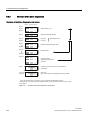
1
ET 200iSP
___________________
Preface
1
___________________
Product overview
SIMATIC
Distributed I/O
ET 200iSP
2
___________________
Commissioning guideline
3
___________________
Configuration options
4
___________________
Installing
5
___________________
Wiring
Operating Instructions
Commissioning and
6
___________________
Diagnostics
7
___________________
Maintenance
General technical
8
___________________
specifications
9
___________________
Terminal modules
10
___________________
Power Supply
11
___________________
Interface module
12
___________________
Digital electronic modules
13
___________________
Analog electronic modules
This document has order number
6ES7152-1AA00-8BA0
01/2010
A5E00247483-04
14
___________________
Other modules
A
___________________
Appendix
Legal information
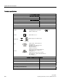
Legal information
Warning notice system
This manual contains notices you have to observe in order to ensure your personal safety, as well as to prevent
damage to property. The notices referring to your personal safety are highlighted in the manual by a safety alert
symbol, notices referring only to property damage have no safety alert symbol. These notices shown below are
graded according to the degree of danger.
DANGER
indicates that death or severe personal injury will result if proper precautions are not taken.
WARNING
indicates that death or severe personal injury may result if proper precautions are not taken.
CAUTION
with a safety alert symbol, indicates that minor personal injury can result if proper precautions are not taken.
CAUTION
without a safety alert symbol, indicates that property damage can result if proper precautions are not taken.
NOTICE
indicates that an unintended result or situation can occur if the corresponding information is not taken into
account.
If more than one degree of danger is present, the warning notice representing the highest degree of danger will
be used. A notice warning of injury to persons with a safety alert symbol may also include a warning relating to
property damage.
Qualified Personnel
The product/system described in this documentation may be operated only by personnel qualified for the specific
task in accordance with the relevant documentation for the specific task, in particular its warning notices and
safety instructions. Qualified personnel are those who, based on their training and experience, are capable of
identifying risks and avoiding potential hazards when working with these products/systems.
Proper use of Siemens products
Note the following:
WARNING
Siemens products may only be used for the applications described in the catalog and in the relevant technical
documentation. If products and components from other manufacturers are used, these must be recommended
or approved by Siemens. Proper transport, storage, installation, assembly, commissioning, operation and
maintenance are required to ensure that the products operate safely and without any problems. The permissible
ambient conditions must be adhered to. The information in the relevant documentation must be observed.
Trademarks
All names identified by ® are registered trademarks of the Siemens AG. The remaining trademarks in this
publication may be trademarks whose use by third parties for their own purposes could violate the rights of the
owner.
Disclaimer of Liability
We have reviewed the contents of this publication to ensure consistency with the hardware and software
described. Since variance cannot be precluded entirely, we cannot guarantee full consistency. However, the
information in this publication is reviewed regularly and any necessary corrections are included in subsequent
editions.
이 기기는 업무용(A급) 전자파 적합기기로서 판매자 또는 사용자는 이 점을 주의하시기 바라며 가정 외의 지역에서 사용하는 것을 목적으로 합니다.
Siemens AG
Industry Sector
Postfach 48 48
90026 NÜRNBERG
GERMANY
A5E00247483-04
Ⓟ 03/2010
Copyright © Siemens AG 2010.
Technical data subject to change
Preface
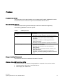
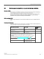
Purpose of the manual
The information in this manual enables you to operate the ET 200iSP distributed I/O device
as a DP slave via an RS 485 IS coupler on the PROFIBUS DP RS 485 IS.
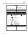
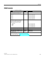
Basic knowledge required
This manual presumes a general knowledge in the field of automation engineering.
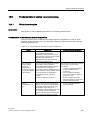
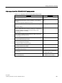
The following qualifications are also required:
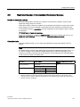
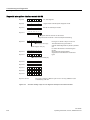
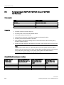
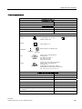
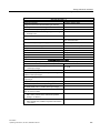
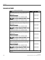
Table 1
Qualified personnel
Activities
Qualifications
Setting up the ET 200iSP
Basic technical training
Knowledge of safety regulations regarding the workplace
Wiring the ET 200iSP
Basic practical training in electro-engineering
Knowledge of the relevant electrotechnical safety
regulations
Knowledge of methods of installing explosion-proof
electrical equipment
Knowledge of safety regulations regarding the workplace
Commissioning the ET 200iSP
Knowledge of all electrical and functional parameters and
properties of the ET 200iSP
Knowledge of the functions and commissioning of
PROFIBUS-DP
Knowledge of the connected encoders, actuators, and
HART field devices
Knowledge of the safety regulations regarding the
workplace, particularly regarding procedures in hazardous
areas
Range of validity of this manual
This manual is valid for the distributed I/O station ET 200iSP.
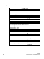
Changes since with the previous edition
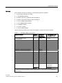
This manual contains the following changes/additions compared to the previous version:
● Terminal modules TM-PS-A UC and TM-PS-B UC
● Power supply PS 120/230 VAC
ET 200iSP
Operating Instructions, 01/2010, A5E00247483-04
3
Preface
Approvals
Refer to Chapter Standards and certifications (Page 195)
CE mark
Refer to Chapter Standards and certifications (Page 195)
Labeling for Australia (C-tick mark)
Refer to Chapter Standards and certifications (Page 195)
Standards
Refer to Chapter Standards and certifications (Page 195)
Position in the information landscape
In the Chapter Order numbers (Page 347) you´ll find a listing of additional sources of
information on the SIMATIC S7 and the ET 200 distributed I/O system.
Guide
This manual describes the hardware of the ET 200iSP distributed I/O station. It consists of
introductory chapters and reference chapters (technical specifications).
● Installing and wiring the ET 200iSP distributed I/O station
● Commissioning and diagnostics of the ET 200iSP distributed I/O station
● Components of the ET 200iSP distributed I/O station
● Order numbers
Special notes
The EC-type-examination certificate and EC certificate of conformity for the ET 200iSP
distributed I/O device are available from Service & Support on the Internet
(http://www.siemens.com/automation/service&support)
Recycling and disposal
Due to the fact that it is low in contaminants, the ET 200iSP distributed I/O station is
recyclable. For ecologically compatible recycling and disposal of your old device, contact a
certificated disposal service for electronic scrap.
4
ET 200iSP
Operating Instructions, 01/2010, A5E00247483-04
Preface
Additional support
Please contact your local Siemens representative and offices if you have any questions
about the products described in this manual and do not find the right answers.
You will find information on who to contact on the Internet
(http://www.siemens.com/automation/partner)
A guide to the technical documentation for the various SIMATIC products and systems is
available on the Internet (http://www.siemens.de/simatic-tech-doku-portal)
The online catalog and the online ordering systems are available on the Internet.
Training Center
We offer a range of courses to help you get started with the ET 200iSP distributed I/O station
and the SIMATIC S7 automation system. For details, please contact your local Training
Center or the Central Training Center in Nuremberg, D -90327 Germany.
Further information is available on the Internet (http://www.sitrain.com)
Technical support
You can contact the Technical Support for all the A&D products by means of the Web form
Internet (http://www.siemens.de/automation/support-request) for the support request.
You can find additional information about our Technical Support on the Web
(http://www.siemens.com/automation/service).
Service & Support on the Internet
In addition to our documentation pool, we offer our complete online knowledge base on the
Internet (http://www.siemens.com/automation/service&support).
There you will find:
● The newsletter, which constantly provides you with up-to-date information on your
products.
● The documentation you need, by using our Service & Support search engine.
● A forum where users and experts from all over the world exchange experiences.
● Your local Automation & Drives representative.
● Information about on-site services, repairs, spare parts, and lots more.
ET 200iSP
Operating Instructions, 01/2010, A5E00247483-04
5
Preface
6
ET 200iSP
Operating Instructions, 01/2010, A5E00247483-04
Table of contents
Preface ...................................................................................................................................................... 3
1
2
3
Product overview ..................................................................................................................................... 13
1.1
Distributed I/O stations.................................................................................................................13
1.2
ET 200iSP Distributed I/O Station................................................................................................15
1.3
ET 200iSP in the Hazardous Area...............................................................................................21
1.4
Figure Integration in the Control System .....................................................................................24
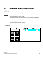
Commissioning guideline......................................................................................................................... 25
2.1
Introduction ..................................................................................................................................25
2.2
Prerequisites ................................................................................................................................25
2.3
Materials and Tools Required to Set Up the Example.................................................................26
2.4
Overview of the Configuration......................................................................................................27
2.5
2.5.1
2.5.2
2.5.3
Installing the the Sample Configuration .......................................................................................28
Installing the ET 200iSP...............................................................................................................28
Installing the S7-400 ....................................................................................................................28
Installing the RS 485-IS Coupler..................................................................................................29
2.6
Wiring the Sample Configuration .................................................................................................29
2.7
Inserting the interface module and the electronics modules .......................................................31
2.8
Setting the PROFIBUS address...................................................................................................32
2.9
2.9.1
2.9.2
Configuring the Example..............................................................................................................33
Configuring S7-400 ......................................................................................................................33
Configuring and assigning parameters for the ET 200iSP ..........................................................35
2.10
Programming the Sample Configuration......................................................................................37
2.11
Putting the Example into Operation .............................................................................................38
2.12
Evaluating the diagnostics ...........................................................................................................38
2.13
Removing and inserting of modules ............................................................................................39
2.14
Wire break of NAMUR encoder on digital input module ..............................................................40
Configuration options............................................................................................................................... 41
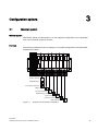
3.1
Modular system............................................................................................................................41
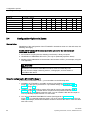
3.2
Electronics modules suitable for your application........................................................................42
3.3
Electronics modules suitable for the terminal modules ...............................................................43
3.4
Configuration Options in Zones ...................................................................................................44
3.5
Use of the ET 200iSP in category M2 of equipment-group I (mining) .........................................48
3.6
Restricted Number of Connectable Electronics Modules ............................................................49
3.7
Maximum configuration of the ET 200iSP ...................................................................................52
ET 200iSP
Operating Instructions, 01/2010, A5E00247483-04
7
Table of contents
4
5
8
3.8
Power Supply of the ET 200iSP.................................................................................................. 53
3.9
Direct data exchange .................................................................................................................. 53
3.10
Identification data I&M................................................................................................................. 54
3.11
Redundancy of the Power Supply............................................................................................... 56
3.12
3.12.1
3.12.2
System configuration in RUN (CiR) ............................................................................................ 58
System modification in a non-redundant system ........................................................................ 58
System modification in a redundant system ............................................................................... 60
3.13
Operating the ET200iSP with older CPUs .................................................................................. 61
3.14
Year of Production of the Module ............................................................................................... 62
3.15
3.15.1
3.15.2
3.15.3
Time stamping............................................................................................................................. 62
Fundamentals of Time Stamping ................................................................................................ 62
Time stamps accurate to 20 ms.................................................................................................. 63
Time synchronization with a flexible time interval ....................................................................... 65
3.16
3.16.1
3.16.2
3.16.3
3.16.4
Counting ...................................................................................................................................... 66
Properties .................................................................................................................................... 66
Principle of operation .................................................................................................................. 67
Configuring counters ................................................................................................................... 69
Assigning parameters to counters .............................................................................................. 72
3.17
3.17.1
3.17.2
3.17.3
3.17.4
Metering frequencies................................................................................................................... 73
Properties .................................................................................................................................... 73
Principle of operation .................................................................................................................. 73
Configuring frequency meters ..................................................................................................... 74
Assigning parameters for the frequency meters ......................................................................... 76
3.18
3.18.1
3.18.2
Redundancy with IM 152............................................................................................................. 77
Introduction ................................................................................................................................. 77
Redundancy with S7 DP Masters ............................................................................................... 78
Installing .................................................................................................................................................. 81
4.1
Installation rules .......................................................................................................................... 81
4.2
Installing the mounting rail .......................................................................................................... 90
4.3
Installing the terminal module for power supply PS.................................................................... 91
4.4
Installing Terminal Modules for the Interface Module and Electronics Modules......................... 94
4.5
Installing the Terminating Module and the Slot Cover ................................................................ 97
4.6
Installing the Slot Number Labels ............................................................................................. 100
Wiring .................................................................................................................................................... 103
5.1
General Rules and Regulations for Wiring................................................................................ 103
5.2
Operating the ET 200iSP with equipotential bonding ............................................................... 105
5.3
Electrical Design of the ET 200iSP ........................................................................................... 108
5.4
5.4.1
5.4.2
5.4.3
5.4.4
5.4.5
5.4.6
Wiring the ET 200iSP................................................................................................................ 109
Wiring Rules for the ET 200iSP ................................................................................................ 109
Wiring Terminal Modules with Screw Terminals ....................................................................... 110
Wiring terminal modules with spring terminals.......................................................................... 111
Grounding the mounting rail...................................................................................................... 112
Wiring terminal module TM-PS-A/ TM-PS-A UC or TM-PS-B/ TM-PS-B UC ........................... 113
Wiring Terminal Modules TM-IM/EM and TM-IM/IM ................................................................. 115
ET 200iSP
Operating Instructions, 01/2010, A5E00247483-04
Table of contents
6
7
5.4.7
5.4.8
5.4.9
5.4.10
Wiring Terminal Modules TM-EM/EM ........................................................................................118
Wiring terminal module TM-RM/RM ..........................................................................................119
Connecting cable shields ...........................................................................................................121
How to Connect a TC Sensor Module .......................................................................................122
5.5
5.5.1
5.5.2
5.5.3
5.5.4
Inserting and labeling the power supply, interface module, and electronic modules ................123
Requirements.............................................................................................................................123
Inserting power supply PS .........................................................................................................124
Inserting and labeling the interface module and electronic modules.........................................125
Inserting and labeling electronic modules 2 DO Relay UC60V/2A............................................128
5.6
Setting the PROFIBUS address.................................................................................................130
Commissioning and Diagnostics............................................................................................................ 133
6.1
Basics of commissioning and diagnostics .................................................................................133
6.2
Project engineering with STEP 7 ...............................................................................................137
6.3
Project Engineering with GSD File and SIMATIC PDM.............................................................138
6.4
Assigning Parameters for the ET 200iSP during Operation using SIMATIC PDM....................141
6.5
Diagnostics Using the Process Image Input Table ....................................................................142
6.6
Status and error LEDs on the ET 200iSP ..................................................................................143
6.7
6.7.1
6.7.2
6.7.3
6.7.4
6.7.5
6.7.6
Commissioning and starting up the ET 200iSP .........................................................................147
Safety Information......................................................................................................................147
Requirements for commissioning...............................................................................................148
Commissioning the ET 200iSP ..................................................................................................149
Figure Starting up the ET 200iSP ..............................................................................................150
Startup of the ET 200iSP with IM 152 redundancy....................................................................151
Startup for time synchronization / time stamping of signal changes..........................................153
6.8
6.8.1
6.8.2
6.8.3
6.8.4
6.8.5
6.8.6
6.8.7
6.8.8
6.8.9
6.8.10
6.8.11
6.8.12
6.8.13
6.8.14
Diagnostics with STEP 7............................................................................................................154
Introduction ................................................................................................................................154
Reading out the diagnostics.......................................................................................................154
Diagnostic messages of the electronic modules........................................................................155
Evaluating interrupts from the ET 200iSP (S7-DP slave/ DPV1 slave) .....................................158
Structure of the slave diagnostics ..............................................................................................160
Station statuses 1 to 3 ...............................................................................................................161
Master PROFIBUS address.......................................................................................................163
Manufacturer's ID.......................................................................................................................163
ID-related diagnostics ................................................................................................................164
Module Status ............................................................................................................................166
Channel-related diagnostics ......................................................................................................167
H-Status (only with the S7-400H and standard redundancy) ....................................................170
Interrupts ....................................................................................................................................171
Diagnostics for incorrect ET 200iSP configuration statuses......................................................181
Maintenance .......................................................................................................................................... 185
7.1
Activities during operation..........................................................................................................185
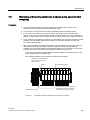
7.2
Removing and inserting electronics modules during operation (hot swapping) ........................187
7.3
Replacing the interface module .................................................................................................189
7.4
Maintenance during operation ...................................................................................................190
7.5
Cleaning .....................................................................................................................................190
7.6
IM 152 firmware update .............................................................................................................191
7.7
Reading service data .................................................................................................................193
ET 200iSP
Operating Instructions, 01/2010, A5E00247483-04
9
Table of contents
8
9
10
11
12
10
General technical specifications ............................................................................................................ 195
8.1
General technical specifications ............................................................................................... 195
8.2
Standards and certifications...................................................................................................... 195
8.3
Electromagnetic compatibility, transport and storage conditions.............................................. 199
8.4
Mechanical and climatic environmental conditions................................................................... 201
8.5
Information on dielectric strength tests, class of protection, degree of protection and rated
voltage of the ET 200iSP .......................................................................................................... 202
Terminal modules .................................................................................................................................. 205
9.1
Overview of the contents........................................................................................................... 205
9.2
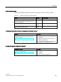
Terminal module TM-PS-A/ TM-PS-A UC and TM-PS-B/ TM-PS-B UC .................................. 206
9.3
Terminal modules TM-IM/EM 60S and TM-IM/EM 60C............................................................ 210
9.4
Terminal module TM-IM/IM ....................................................................................................... 214
9.5
Terminal modules TM-EM/EM 60S and TM-EM/EM 60C......................................................... 217
9.6
Terminal module TM-RM/RM.................................................................................................... 220
Power Supply ........................................................................................................................................ 223
10.1
Power supply PS 24 VDC ......................................................................................................... 223
10.2
Power supply PS 120/230 VAC ................................................................................................ 226
Interface module .................................................................................................................................... 231
11.1
Interface module IM 152 ........................................................................................................... 231
11.2
Parameters for the IM 152 ........................................................................................................ 235
11.3
Identification and Message Functions (I&M)............................................................................. 236
11.4
11.4.1
11.4.2
11.4.3
11.4.4
11.4.5
11.4.6
11.4.7
11.4.8
11.4.9
11.4.10
Description of the parameters for the IM 152............................................................................ 236
Operation at Preset <> Actual Configuration ............................................................................ 236
Self-diagnostics......................................................................................................................... 236
Redundant power supply diagnostics ....................................................................................... 237
Diagnostic interrupts ................................................................................................................. 237
Hardware interrupts................................................................................................................... 237
Time stamping / edge evaluation .............................................................................................. 237
Data format ............................................................................................................................... 238
Noise suppression..................................................................................................................... 238
Temperature unit....................................................................................................................... 238
Slot reference junction/reference junction input........................................................................ 238
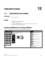
Digital electronic modules ...................................................................................................................... 239
12.1
Digital electronics module 8 DI NAMUR ................................................................................... 239
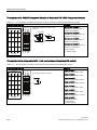
12.2
Digital electronics module 4 DO................................................................................................ 247
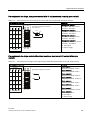
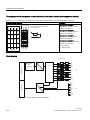
12.3
Digital electronic module 2 DO Relay UC60V/2A ..................................................................... 259
12.4
Identification and Message Functions (I&M)............................................................................. 264
12.5
12.5.1
12.5.2
12.5.3
Parameters of the digital electronic modules ............................................................................ 264
Digital electronic module 8 DI NAMUR ..................................................................................... 264
Digital electronic module 4 DO ................................................................................................. 267
Digital electronic module 2 DO Relay UC60V/2A ..................................................................... 268
ET 200iSP
Operating Instructions, 01/2010, A5E00247483-04
Table of contents
12.6
12.6.1
12.6.2
12.6.3
12.6.4
12.6.5
12.6.6
13
14
Description of the parameters of the digital electronic modules ................................................268
Time stamping............................................................................................................................268
Pulse stretching..........................................................................................................................269
Flutter monitoring .......................................................................................................................270
Shutdown signal.........................................................................................................................271
Parameters for counting.............................................................................................................271
Parameters for metering frequencies ........................................................................................272
Analog electronic modules..................................................................................................................... 275
13.1
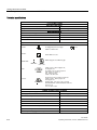
Behavior of the analog modules during operation and in the event of problems ......................275
13.2
Analog electronics module 4 AI I 2WIRE HART ........................................................................276
13.3
Analog electronics module 4 AI I 4WIRE HART ........................................................................280
13.4
Analog electronics module 4 AI RTD.........................................................................................285
13.5
Analog electronics module 4 AI TC ...........................................................................................290
13.6
Analog electronics module 4AO I HART....................................................................................295
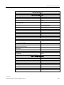
13.7
Identification and Message Functions (I&M)..............................................................................299
13.8
13.8.1
13.8.2
13.8.3
13.8.4
Representation of analog values ...............................................................................................299
Overview ....................................................................................................................................299
Analog value representation for measuring ranges with SIMATIC S7 ......................................300
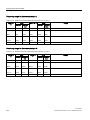
Measuring ranges of the analog input modules in S7 format ....................................................302
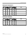
Output ranges of the analog output modules in S7 format ........................................................310
13.9
13.9.1
Fundamentals of analog value processing ................................................................................311
Wiring thermocouples ................................................................................................................311
13.10
13.10.1
13.10.2
13.10.3
13.10.4
13.10.5
13.10.6
13.10.7
13.10.8
Basics of HART..........................................................................................................................315
Introduction ................................................................................................................................315
Properties of HART....................................................................................................................315
Principles of HART operation.....................................................................................................316
Integration of HART field devices with ET 200iSP.....................................................................318
Using HART ...............................................................................................................................319
HART Fast Mode .......................................................................................................................322
IEEE tags ...................................................................................................................................323
HART data records ....................................................................................................................326
13.11
13.11.1
13.11.2
13.11.3
Parameters of the analog electronic modules ...........................................................................328
Parameters for analog electronics modules 4 AI I 2WIRE HART, 4 AI I 4WIRE HART............328
Parameters relevant for 4 AI RTD, 4 AI TC analog electronics modules ..................................331
Parameters for analog electronics module 4AO I HART ...........................................................332
13.12
13.12.1
13.12.2
13.12.3
13.12.4
13.12.5
13.12.6
13.12.7
Parameter description of the analog electronic modules...........................................................334
Reference junction / reference junction number ........................................................................334
Smoothing ..................................................................................................................................335
Assigning the channel and IEEE tag .........................................................................................336
HART repetitions........................................................................................................................338
HART Fast Mode .......................................................................................................................338
HART warning............................................................................................................................339
HART diagnostics ......................................................................................................................339
Other modules ....................................................................................................................................... 341
14.1
Reserve module .........................................................................................................................341
14.2
Watchdog module ......................................................................................................................343
ET 200iSP
Operating Instructions, 01/2010, A5E00247483-04
11
Table of contents
A
Appendix................................................................................................................................................ 347
A.1
Order numbers .......................................................................................................................... 347
A.2
A.2.1
Dimensional drawings ............................................................................................................... 353
Dimensional drawings ............................................................................................................... 353
A.3
A.3.1
A.3.2
A.3.3
A.3.4
A.3.5
A.3.6
A.3.7
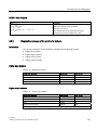
Reaction times .......................................................................................................................... 356
Reaction times .......................................................................................................................... 356
Response times at the DP master ............................................................................................ 356
Reaction times on the ET 200iSP ............................................................................................. 357
Reaction times of digital input modules .................................................................................... 357
Reaction times for the digital output modules ........................................................................... 357
Reaction times for analog input modules.................................................................................. 358
Reaction times for analog output modules................................................................................ 359
A.4
A.4.1
A.4.2
A.4.3
A.4.4
A.4.5
A.4.6
A.4.7
A.4.8
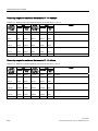
Address space of the inputs and outputs.................................................................................. 361
Digital input module................................................................................................................... 361
Digital output module ................................................................................................................ 363
Digital output module 2 DO Relay UC60V/2A........................................................................... 364
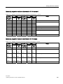
Analog input modules................................................................................................................ 364
Analog output modules ............................................................................................................. 365
Analog input modules with HART (4 AI I 2WIRE HART, 4 AI I 4WIRE HART) ........................ 366
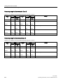
Analog output module with HART (4 AO I HART) .................................................................... 367
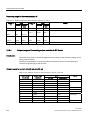
Watchdog module ..................................................................................................................... 368
A.5
A.5.1
A.5.2
A.5.3
A.5.4
A.5.5
Lightning and overvoltage protection ........................................................................................ 369
Overview ................................................................................................................................... 369
Lightning protection zone concept ............................................................................................ 370
Rules for the interfaces between Lightning Protection Zones 0 and 1 ..................................... 372
Rules for the interfaces between lightning protection zones 1 and 2 and higher ..................... 374
Application example for protection of ET 200iSP from overvoltages........................................ 375
Glossary ................................................................................................................................................ 379
Index...................................................................................................................................................... 387
12
ET 200iSP
Operating Instructions, 01/2010, A5E00247483-04
Product overview
1.1
1
Distributed I/O stations
Distributed I/O stations - Area of application
When a system is set up, it is common for the inputs to and outputs from the process to be
incorporated centrally in the automation system.
If the inputs/outputs are located at greater distances from the automation system, the wiring
can become very extensive and complex, and electromagnetic interferences can impair
reliability.
In such systems, it is often advisable to use distributed I/O stations:
● The controller CPU is located centrally.
● the I/O devices are distributed on site
● The powerful PROFIBUS DP with its high data transmission rates ensures smooth
communication between the controller CPU and the I/O devices.
● Less installation effort since less cables are required.
PROFIBUS DP
PROFIBUS DP is an open bus system based on IEC 61784-1:2002 Ed1 CP 3/1 with the
"DP" transmission protocol (DP stands for distributed peripheral I/O).
Physically, PROFIBUS DP is either an electrical network based on a shielded two-wire cable
or an optical network based on a fiber-optic cable.
The "DP" protocol allows fast, cyclic data exchange between the control CPU and the
distributed I/O devices.
PROFIBUS RS 485-IS
In contrast to PROFIBUS DP, PROFIBUS DP RS 485-IS is intrinsically safe (protection type
- intrinsically safe i). The RS 485 IS coupler ensures intrinsic safety and acts as a safety
barrier. You can find addtional information on PROFIBUS RS 485-IS in the "PROFIBUS
RS485-IS User and Installation Guideline (http://www.profibus.com)"
DP master and DP slaves
The link between the control CPU and the distributed I/O devices is the DP master. The DP
master exchanges data with the distributed I/O devices via PROFIBUS DP and monitors the
PROFIBUS DP.
The distributed I/O devices (= DP slaves) prepare the sensor and actuator data on-site so
that they can be transmitted to the controller CPU via PROFIBUS DP.
ET 200iSP
Operating Instructions, 01/2010, A5E00247483-04
13
Product overview
1.1 Distributed I/O stations
Devices that can be connected to PROFIBUS-DP devices
An extremely wide range of devices can be connected on the PROFIBUS DP as a DP
master or as DP slaves, provided their behavior complies with IEC 61784-1:2002 Ed1 CP
3/1. These include the devices of the following product families:
● SIMATIC S7/M7/C7
● SIMATIC programming devices/PCs
● SIMATIC HMI (operator panel (OP), operator station (OS), and text display (TD) operator
control and monitoring devices)
● Distributed I/O stations
● Devices from other manufacturers
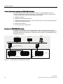
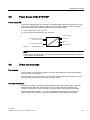
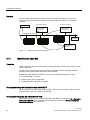
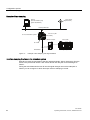
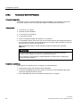
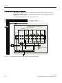
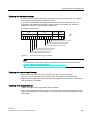
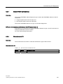
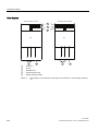
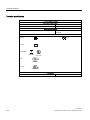
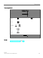
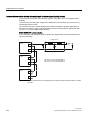
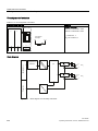
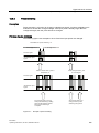
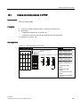
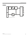
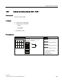
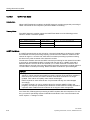
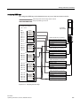
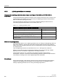
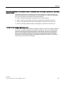
Structure of a PROFIBUS DP network
The figure below illustrates a typical PROFIBUS DP network structure. The DP master is
integrated in the relevant device, for example the S7-400 as a PROFIBUS DP interface. The
ET 200iSP distributed I/O stations are connected to the DP masters via PROFIBUS DP and
PROFIBUS RS 485-IS.
6
(70
3*3&
352),%86'3
56,6&RXSOHU
352),%8656,6
(7L63
+D]DUGRXVDUHD=RQH
Figure 1-1
14
(7L63
+D]DUGRXVDUHD=RQH
Typical structure of a PROFIBUS DP network
ET 200iSP
Operating Instructions, 01/2010, A5E00247483-04
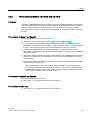
Product overview
1.2 ET 200iSP Distributed I/O Station
1.2
ET 200iSP Distributed I/O Station
Definition
The ET 200iSP distributed I/O station is a highly modular and intrinsically safe DP slave with
degree of protection IP 30.
Area of application
The ET 200iSP distributed I/O station can be operated in potentially explosive atmospheres
characterized by gas and dust:
Approval
ET 200iSP Station*
Inputs and outputs
ATEX
Zone 1, Zone 21
up to Zone 0, Zone 20 **
IECEx
Zone 2, Zone 22
up to Zone 0, Zone 20 **
* In combination with an appropriate enclosure
** for electronic module 2 DO Relay UC60V/2A: up to Zone 1, Zone 21
The ET 200iSP distributed I/O station can, of course, also be used in the safety area.
You can insert almost any combination of ET 200iSP I/O modules directly next to the
interface module that transfers the data to the DP master. This means you can adapt the
configuration to suit your on-site requirements.
Every ET 200iSP consists of a power supply module, an interface module, and a maximum
of 32 electronic modules (for example digital electronics modules). Remember not to exceed
the maximum current consumption.
Terminal modules and electronic modules
In principle, the ET 200iSP distributed I/O station consists of various passive terminal
modules onto which you plug the power supply and the electronic modules.
The ET 200iSP is connected to PROFIBUS RS 485-IS by means of a connector on terminal
module TM-IM/EM. Every ET 200iSP is a DP slave on the PROFIBUS RS 485-IS.
ET 200iSP
Operating Instructions, 01/2010, A5E00247483-04
15
Product overview
1.2 ET 200iSP Distributed I/O Station
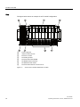
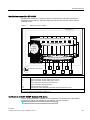
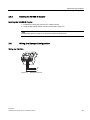
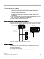
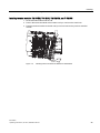
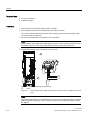
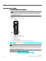
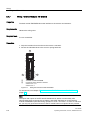
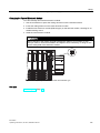
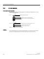
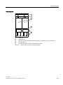
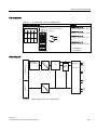
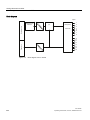
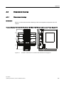
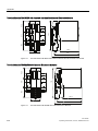
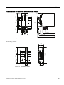
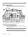
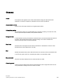
View
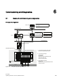
The figure below shows an example of an ET 200iSP configuration.
8
①
②
③
④
⑤
⑥
⑦
⑧
Power supply PS
Interface module IM 152
Electronic modules
Terminating module
Terminal module TM-RM/RM
TM-EM/EM terminal modules
TM-IM/EM terminal module
Terminal module TM-PS-A/ TM-PS-A UC
Figure 1-2
16
View of the ET 200iSP distributed I/O station
ET 200iSP
Operating Instructions, 01/2010, A5E00247483-04
Product overview
1.2 ET 200iSP Distributed I/O Station
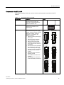
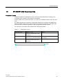
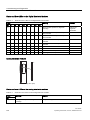
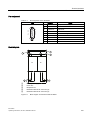
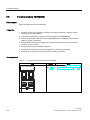
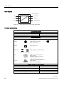
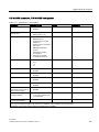
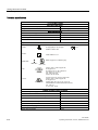
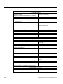
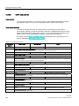
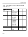
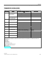
Components of the ET 200iSP
The following table provides an overview of the most important components of the ET
200iSP.
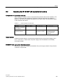
Table 1- 1
Components of the ET 200iSP
Component
Enclosure
Function
...is an additional measure to further
increase safety avoiding the
production of high temperatures,
sparks and electric arcs.
Mounting rail
...is the rack for the ET 200iSP. You
install the ET 200iSP on the
mounting rail.
Terminal module
...carries the wiring and
accommodates the power supply
module, interface module, and the
electronic modules. Terminal
modules are available in the
following variants:
TM-PS-A for the power supply
PS 24 VDC
TM-PS-B for the redundant
power supply PS 24 VDC
TM-PS-A UC for the power
supply PS 120/230 VAC and
PS 24 VDC (Product version 6
and higher)
TM-PS-B UC for the redundent
PS 120/230 VAC and PS 24
VDC redundant power supply
(Product version 6 and higher)
TM-IM/EM for the interface
module
TM-IM/IM for the redundant
interface module
TM-EM/EM for the electronic
modules
TM-RM/RM for the electronic
module 2DO Relay UC60V/2A
Image
7036$
7036$8&
7036%
7036%8&
70,0(0
70,0,0
70(0(0
705050
ET 200iSP
Operating Instructions, 01/2010, A5E00247483-04
17
Product overview
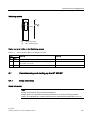
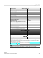
1.2 ET 200iSP Distributed I/O Station
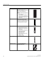
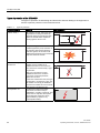
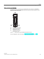
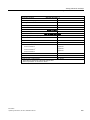
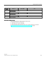
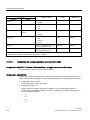
18
Component
Power supply PS
Function
Image
...is plugged into terminal module
TM-PS-A / TM-PS-A UC or
TM-PS-B / TM-PS-B UC. The power
supply module supplies the
electronic circuits and sensors with
voltage.
PS 24 VDC power supply to TMPS-A/ TM-PS-B
Power supply PS 120/230 VAC
and PS 24 VDC (Product version
6 and higher) to TM-PS-A UC/
TM-PS-B UC
Interface module
...is plugged onto the terminal
module. The interface module
connects the ET 200iSP with the DP
master and conditions the data for
the inserted electronic modules.
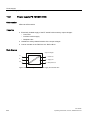
Electronic module
...is inserted onto the terminal
module and determines the function:
Digital electronic modules for
NAMUR sensors, digital output,
relay module
Analog electronic modules with
current and resistance
measurement circuit,
thermoresistor and
thermocouples, analog output
Reserve module
Watchdog module
Terminating module
...completes the ET 200iSP.
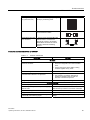
RS 485-IS Coupler
...couples PROFIBUS DP to
PROFIBUS RS 485-IS.
ET 200iSP
Operating Instructions, 01/2010, A5E00247483-04
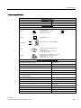
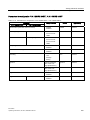
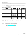
Product overview
1.2 ET 200iSP Distributed I/O Station
PROFIBUS cable with
bus connector
...interconnects the PROFIBUS RS
485-IS nodes or connects the
RS 485-IS coupler to ET 200iSP.
PROFIBUS connector RS 485-IS,
including switched terminating
resistor
...are used for identifying the slots
on the terminal module.
Slot number labels
Image
Function
...for machine labeling or printing
80 strips per labeling sheet
Component
Labeling sheet (DIN
A4, perforated, foil)
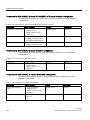
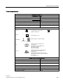
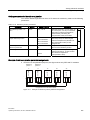
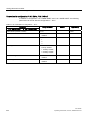
Features and benefits of the ET 200iSP
Table 1- 2
Features and benefits
Properties
Benefits
Structure
Modular structure based on 4- or 8-channel
electronic modules
Station design optimized to contain costs
Reduced configuration and documentation
effort
Space savings due to the ability to string
modules together in any order
Extensive range of electronic modules
Broad area of application
Permanent wiring due to the separation of
mechanical and electronic components
Integrated power bus
Reduced effort required for wiring
Prewiring possible
Hot swapping of modules while the ET
200iSP is operating when at least two
electronic modules are present.
Connection system
Screw or spring terminals
Use of most suitable terminating technique
Intrinsically safe inputs and outputs complying
with Ex ia IIC
Intrinsically safe sensors, actuators and HART
field devices up to Zone 0/ 20 can be connected
Automatic coding of the I/O modules
Quick and reliable module replacement
Large label
Adequate space for clear identification
Disabling all digital outputs of a module by an
intrinsically safe switching signal
Control of the outputs independent of the process
image
ET 200iSP
Operating Instructions, 01/2010, A5E00247483-04
19
Product overview
1.2 ET 200iSP Distributed I/O Station
Properties
Benefits
Functionality
Changing parameter settings and expansion
during operation
No restart of the ET 200iSP necessary
Time stamping, flutter monitoring, pulse
stretching
Efficient monitoring of the inputs
Counting and frequency measurement
Options for use in technological applications
Identification data I&M
Unique identification/assignment of the modules
used (for example, for validation, quality
assurance)
Analog value display in S7 format
IEEE tags
Analog modules with HART support up to four
IEEE tags in IEEE754 format
Redundancy of IM 152 (V2.0 and higher)
Redundancy of the power supply PS
with TM-PS-A/ TM-PS-A UC
on S7-DP masters (e.g. S7-400H)
with software redundancy
DP master
All ET 200iSP modules support communication with DP masters that are compliant with
IEC 61784-1:2002 Ed1 CP 3/1 and operate with "DP" transmission protocol (DP stands for
distributed peripherals or distributed I/O).
20
ET 200iSP
Operating Instructions, 01/2010, A5E00247483-04
Product overview
1.3 ET 200iSP in the Hazardous Area
1.3
ET 200iSP in the Hazardous Area
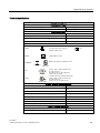
Properties of zones
Hazardous areas are classified into zones. The zones are distinguished according to the
probability of the existence of an explosive atmosphere.
The ET 200iSP can be used in the Zone 1/ 21, Zone 2/ 22 hazardous areas, and in the safe
area.
ET 200iSP supports the connection of intrinsically safe sensors, actuators and HART field
devices located in Zone 0/20 and in the safe area. The sensors, actuators, and HART field
devices must be certified for operation in the corresponding hazardous areas.
You will find an overview of the zone divisions in the following table:
Table 1- 3
Classification of zones
Hazardous areas
Explosion hazard
Example
Zone 0/ 20
Long-term, frequent or permanent
presence of explosive gas or dust
atmosphere
Within containers.
Zone 1/ 21
Infrequent presence of potentially
explosive gas or dust atmosphere
In the region of openings for filling
and emptying.
Zone 2/ 22
Rare or short-term presence of
potentially explosive gas or dust
atmosphere
Areas bordering on zone 1/ 21
For more information, refer to the "Principles of explosion protection
(http://support.automation.siemens.com/WW/view/en/12521844)" manual.
ET 200iSP
Operating Instructions, 01/2010, A5E00247483-04
21
Product overview
1.3 ET 200iSP in the Hazardous Area
Types of protection of the ET 200iSP
The types of protection include design and electrical measures relating to the equipment to
achieve explosion protection in the hazardous areas.
Table 1- 4
Types of protection
Type of Protection
Meaning
Intrinsic safety i
All voltages, currents, inductance and
capacitance occurring are limited by
electrical measures (intrinsically safe) sparks or thermal effects capable of
causing ignition cannot occur.
Representation
Explosion-proof enclosure The power supply module is installed in
d
a stable (explosion-proof) enclosure. If
the explosive atmosphere within the
enclosure ignites, the enclosure will
withstand the explosion and contain the
explosion within the module.
Increased-safety
enclosure e
In the Zone 1 hazardous area, the ET
200iSP must be installed in an
additional enclosure. The enclosure
must have the increased safety e type
of protection.
This type of protection involves
additional measures to avoid the
occurrence of high temperatures,
sparks and arc-over.
In the Zone 2 hazardous area, this type
of protection is unnecessary. Here, the
ET 200iSP must simply be installed in
an enclosure suitable for zone 2 with at
least degree of protection IP 54.
Encapsulation "m"
22
In electronic module 2 DO Relay
UC60V/2A, the internal relay is
embedded in a sealing compound. This
means that an explosive atmosphere
surrounding the equipment can be
ignited neither by sparks nor by
unacceptable heating.
ET 200iSP
Operating Instructions, 01/2010, A5E00247483-04
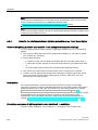
Product overview
1.3 ET 200iSP in the Hazardous Area
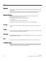
Identification codes of the ET 200iSP
Equipment for operation in hazardous areas is marked with an identifier indicating the
hazardous environments in which the equipment can be used. The ET 200iSP has the
following marks:
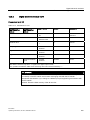
Table 1- 5
Markings of the ET 200iSP
+RXVLQJ([H
%DVHDVVHPEO\(7L63([GHLDLE,,&7
,0DQG(0V([LE,,&7
3RZHU
VXSSO\
([GH>LE@
,,&7
,QSXWVDQGRXWSXWV([LD,,&7
352),%8656,6
+D]DUGRXVDUHD=RQH
P$
Meaning:
Ex:
Explosion protection marking
ia:
Type of protection intrinsic safety (up to zone 0)
ib:
Type of protection intrinsic safety (up to zone 1)
d:
Type of protection explosion-proof enclosure
e:
Type of protection increased safety
IIC:
Explosion group for hydrogen
T4:
Temperature Class: Maximum permitted surface temperature 135 °C
* Electronic module 2 DO Relay UC60V/2A: Ex eibmb IIC T4
** Terminal module TM-RM/RM: Ex deib IIC T4
Certifications of the ET 200iSP distributed I/O station
The EC-type-examination certificate and EC certificate of conformity for the ET 200iSP
distributed I/O station are available on the Internet: "Service & Support
(http://www.siemens.com/automation/service&support)"
ET 200iSP
Operating Instructions, 01/2010, A5E00247483-04
23
Product overview
1.4 Figure Integration in the Control System
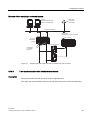
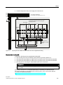
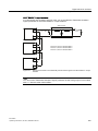
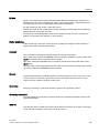
1.4
Figure Integration in the Control System
PCS 7
PCS 7 is a powerful process control system. With PCS 7, the ET 200iSP is directly attached
to the control system.
&RPSRQHQWVRI3&6
3&
3&626
2SHUDWRUFRQWURODQG
PRQLWRULQJZLWK:LQ&&
,QGXVWULDO(WKHUQHW
6
&RQILJXUDWLRQDQG
SDUDPHWHU
DVVLJQPHQWZLWK
67(3
3&
3&6(6
&RQILJXULQJYLD
*6'ILOH
6HWWLQJ3DUDPHWHUV
ZLWK6,0$7,&3'0
+LJKHUOHYHOOD\HU
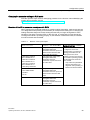
352),%86'3
56,6&RXSOHU
352),%8656,6
(7L63LQHQFORVXUH
/RZHVWOHYHODFWXDWRUV
VHQVRUVILHOGGHYLFHV
+D]DUGRXVDUHD=RQH
=RQH
Figure 1-3
24
P$
Integration in the Control System
ET 200iSP
Operating Instructions, 01/2010, A5E00247483-04
Commissioning guideline
2.1
2
Introduction
Introduction
This manual guides you step-by-step through a concrete example until you have created a
functioning application. While working through the example, you will learn the basic
hardware and software functions of your ET 200iSP.
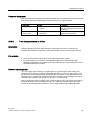
2.2
Prerequisites
Prerequisites
The following requirements must be met:
● You must be familiar with the basics of electrical and electronic engineering and the
procedures relating to potentially explosive atmospheres and have experience working
with computers and Microsoft(R) Windows(TM) 2000/ XP.
● STEP 7 (version 5.3 Service Pack 1 or higher and the current HW update) or PCS 7
(version 6.1 or higher) is completely installed on your programming device and you have
a basic knowledge of STEP 7. You may also use older versions of STEP 7.
● If you implement this example in a hazardous area, you must adhere to all the rules and
regulations explained and listed in this manual.
Note
Always observe the guidelines according to EN 60 079-17 when performing operation
checks. This standard also contains the directives of international standard IEC 60 07917.
DANGER
When laying cables and wiring in hazardous areas, make sure that you adhere to the
installation regulations complying with EN 60 079-14 and any regulations specific to
your country.
When operating the ET 200iSP in areas with combustible dust, you need to observe EN
61241-14 as well.
ET 200iSP
Operating Instructions, 01/2010, A5E00247483-04
25
Commissioning guideline
2.3 Materials and Tools Required to Set Up the Example
WARNING
When used in plants or systems, the ET 200iSP is subject to special rules and
regulations depending on the area of application.
Please note the current safety regulations for the prevention of accidents, e.g. IEC 204
(EMERGENCY-OFF equipment).
You risk severe injuries or damage to machines and equipment if you ignore these
directives.
See also
Basics of commissioning and diagnostics (Page 133)
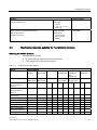
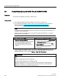
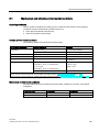
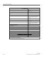
2.3
Materials and Tools Required to Set Up the Example
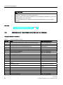
Required materials and tools
Table 2- 1
Required materials and tools
Quantity
Article
Order Number (Siemens)
1
SIMATIC S7-300, mounting rail L=160 mm (for RS 485-IS coupler)
6ES7390-1AB60-0AA0
2
SIMATIC S7-300, mounting rail L=480 mm (for ET 200iSP)
6ES7390-1AE80-0AA0
1
Enclosure for ET 200iSP with degree of protection Ex e (for use of
ET 200iSP in the zone 1 potentially explosive area)
Contact your Siemens
representative
1
TM-PS-A terminal module
6ES7193-7DA10-0AA0
1
Terminal module TM-IM/EM with terminating module
6ES7193-7AA00-0AA0
2
Terminal module TM-EM/EM
6ES7193-7CA00-0AA0
1
Interface module IM 152
6ES7152-1AA00-0AB0
1
Power supply PS 24 VDC
6ES7138-7EA01-0AA0
2
8 DI NAMUR
6ES7131-7RF00-0AB0
3
4 DO DC17,4/27mA SHUT DOWN "H"
6ES7132-7RD11-0AB0
1
RS 485-IS Coupler
6ES7972-0AC80-0XA0
2
PROFIBUS bus connector (for master and RS 485-IS coupler)
6ES7972-0BB50-0XA0
1
PROFIBUS bus connector RS 485-IS up to 1.5 MBaud incl. terminating
resistor
6ES7972-0DA60-0XA0
1
PROFIBUS-DP cable
for example, 6XV1830-0EH10
2
NAMUR sensor
for example, BERO 3RG 46121NA00
1
1-wire On button
normal suppliers
3
LEDs with series resistor
normal suppliers
1
Universal rack
6ES7400-1TA01-0AA0
1
Power supply module PS S7-400
6ES7407-0DA02-0AA0
1
CPU CPU S7-416-3 DP
6ES7416-3XR05-0AB0
26
ET 200iSP
Operating Instructions, 01/2010, A5E00247483-04
Commissioning guideline
2.4 Overview of the Configuration
Quantity
Article
Order Number (Siemens)
1
Programming device (PG) with PROFIBUS DP interface, installed
STEP 7 software (Version 5.3, Service pack 1 or higher and the current
HW update), communications processor CP 5611 and PG cable
various
1
Screwdriver with 3 mm blade
normal suppliers
1
Screwdriver with 4,5 mm blade
normal suppliers
1
Cutting tool for the mounting rails
normal suppliers
1
Cable cutters and wire stripping tools
normal suppliers
1
Tool for crimping wire-end ferrules
normal suppliers
1
Cable for grounding DIN rails with 10 mm cross-section with terminal
end to fit M6, length to suit local situation
normal suppliers
1
Cable lug for M6
normal suppliers
mm2
1
Flexible wire with 1
cross section with suitable ferrules with
insulation collar, length 6 mm
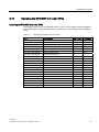
2.4
normal suppliers
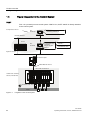
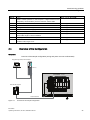
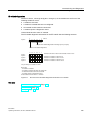
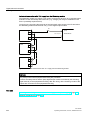
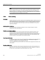
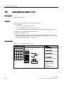
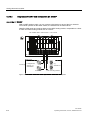
Overview of the Configuration
Overview
Overview of the sample configuration (wiring and power sources not illustrated)
3URJUDPPLQJGHYLFHZLWK&3
6
',1$085 '2
56,6&RXSOHU
*URXQGEXV3$
Figure 2-1
Overview of the sample configuration
ET 200iSP
Operating Instructions, 01/2010, A5E00247483-04
27
Commissioning guideline
2.5 Installing the the Sample Configuration
2.5
Installing the the Sample Configuration
2.5.1
Installing the ET 200iSP
Setting up the ET 200iSP
1. Install the mounting rail (480 mm) in the Ex e enclosure that you have previously secured
to a firm base.
2. Install the modules starting at the left-hand end of the rail. Begin with terminal module
TM-PS-A (fit onto top of rail - push in at the bottom - fasten with two screws). Continue
with the remaining modules (fit onto top of rail - push in at the bottom - push to the left).
Insert the modules in the following order:
– TM-PS-A terminal module
– TM-IM/EM terminal module
– 2 x terminal module TM-EM/EM
– Terminating module
2.5.2
Installing the S7-400
Installing the S7-400
1. Install the rack on a stable surface. Refer to Operating Instructions
Automation System S7-400: Hardware and Installation
(http://support.automation.siemens.com/WW/view/en/1117849)
2. On the left of the rack, start by installing the separete modules (hang in - swivel into
position - screw on tightly). Insert the modules in the following order:
– Power supply module PS
– Central module CPU 416-3 DP
28
ET 200iSP
Operating Instructions, 01/2010, A5E00247483-04
Commissioning guideline
2.6 Wiring the Sample Configuration
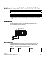
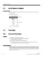
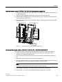
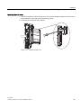
2.5.3
Installing the RS 485-IS Coupler
Installing the RS 485-IS Coupler
1. Install the mounting rail (160 mm) on a stable surface.
2. Hang the RS 485-IS coupler onto the rail and then swivel it in.
Note
Install the RS 485-IS coupler in an enclosure outside of the Ex area.
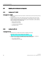
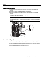
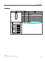
2.6
Wiring the Sample Configuration
Wiring the TM-PS-A
3$
0
/
Figure 2-2
Wiring the TM-PS-A
ET 200iSP
Operating Instructions, 01/2010, A5E00247483-04
29
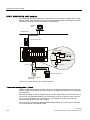
Commissioning guideline
2.6 Wiring the Sample Configuration
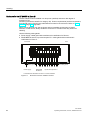
352),%8656,6
7R(7L63
6WUDLQUHOLHIDQGVKLHOGVXSSRUW
352),%8656,6FRQQHFWLRQ
/('V
352),%8656,6EXVWHUPLQD
WLRQVZLWFK
352),%86'3FRQQHFWLRQ;'3
93RZHUVXSSO\
$&
352),%86'3
)URP&38'3
'&
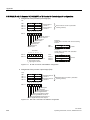
Figure 2-3
9'&
Wiring the RS 485-IS Coupler
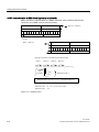
Connect the following:
1. The programming device (PG) and the CPU 416-3 DP (interface: X1 MPI) with a
programming device cable.
2. The mounting rail of the S7-400, including the grounding conductor.
3. The mounting rail of the ET 200iSP and the power supply PS with the equipotential
bonding PA. Use the grounding bolts to secure to the mounting rail.
4. The CPU 416-3 DP (interface: X2 DP) with the RS 485-IS coupler, as shown above using
a PROFIBUS DP cable (PROFIBUS connector 6ES7972-0BB50-0XA0).
5. The interface IM 152 with the RS-485-IS coupler, as shown earlier. Use a PROFIBUS DP
cable (PROFIBUS connector 6ES7972-0BB50-0XA0).
6. The TM PS-A, the RS 485-IS Coupler and the power supply module PS S7-400 with the
power supply.
30
ET 200iSP
Operating Instructions, 01/2010, A5E00247483-04
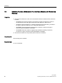
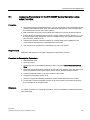
Commissioning guideline
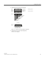
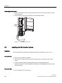
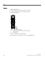
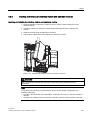
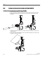
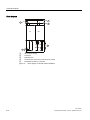
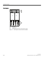
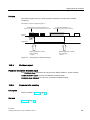
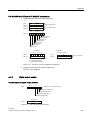
2.7 Inserting the interface module and the electronics modules
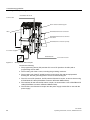
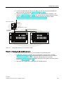
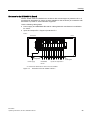
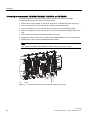
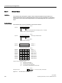
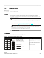
Wire the ET 200iSP as shown below:
5
2 x 8 DI NAMUR
3 x 4 DO DC 17, 4/27 mA
LEDs
NAMUR sensor
Terminals
Figure 2-4
2.7
4
①
②
③
④
⑤
Wiring ET 200iSP modules
Inserting the interface module and the electronics modules
Inserting Modules
Insert the modules in the following order:
● Power supply PS 24 VDC
● Interface module IM 152
● 2 x 8 DI NAMUR
● 3 x 4 DO DC17.4V/27mA
See also
Installing Terminal Modules for the Interface Module and Electronics Modules (Page 94)
ET 200iSP
Operating Instructions, 01/2010, A5E00247483-04
31
Commissioning guideline
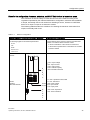
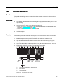
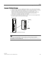
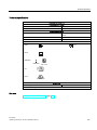
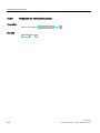
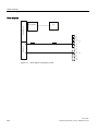
2.8 Setting the PROFIBUS address
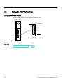
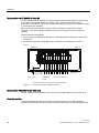
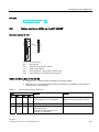
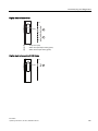
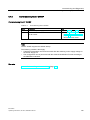
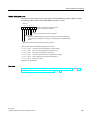
2.8
Setting the PROFIBUS address
Setting the PROFIBUS address
Set PROFIBUS address 3 on the interface module IM 152.
,QWHUIDFHPRGXOH
2)) 21
([DPSOH
'3DGGUHVV
UHVHUYHG
Figure 2-5
Setting PROFIBUS address 3
See also
Setting the PROFIBUS address (Page 130)
32
ET 200iSP
Operating Instructions, 01/2010, A5E00247483-04
Commissioning guideline
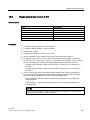
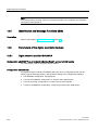
2.9 Configuring the Example
2.9
Configuring the Example
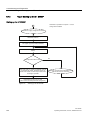
2.9.1
Configuring S7-400
Step 1
Open STEP 7.
Step 2
If the New Project Wizard opens, close it with Cancel.
Step 3
Go to the main menu of the SIMATIC Manager and select File > New. A dialog box opens in
which you enter "ET 200iS" as the name and then close the dialog with OK.
Step 4
Select Insert > Station and then click SIMATIC 400 Station in the list. An icon with the name
SIMATIC 400(1) appears in the right-hand pane of the project window.
Step 5
Now double-click on the icon of the SIMATIC 400 station in the SIMATIC Manager. An icon
labeled "Hardware" now appears in the right-hand pane of the window. Double-click on this
icon. HW Config opens.
Step 6
If no catalog with components is displayed on the right-hand side of the window, activate the
display by selecting View > Catalog in the menu.
Expand the SIMATIC 400 folder and RACK-400 folder until you see UR1. Double-click on
this icon.
Step 7
Select slot 1 (it changes to blue) and then return to the catalog and open the folders
SIMATIC 400, PS 400 and Standard PS 400 until you can see PS 407 4A. Double-click on
this icon. The power supply module now occupies slot 1.
Step 8
Next, select slot 3, then go to SIMATIC 400 via CPU 400, CPU 416-3 DP, and
6ES7416-3XR05-0AB0. A double-click opens a window titled "Properties-PROFIBUS
interface DP". Acknowledge this with OK. The CPU is entered in slot 2.
ET 200iSP
Operating Instructions, 01/2010, A5E00247483-04
33
Commissioning guideline
2.9 Configuring the Example
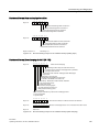
Step 9
In the lower left-hand window, locate the row labeled DP and select it. Right-click on the row
and select Object Properties. The "Properties DP" dialog opens. Click the Properties button
and in the next dialog, click New. A new DP subnet operating at 1.5 Mbps is created. Now
confirm by clicking OK three times in succession.
Step 10
In the main menu, you can save the changes with Station > Save and Compile.
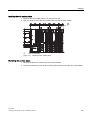
Figure 2-6
34
Configuring the S7-400
ET 200iSP
Operating Instructions, 01/2010, A5E00247483-04
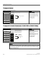
Commissioning guideline
2.9 Configuring the Example
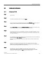
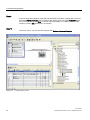
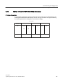
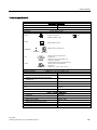
2.9.2
Configuring and assigning parameters for the ET 200iSP
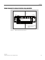
Step 1
In the upper left-hand window of HW Config, click on the stylized PROFIBUS to select it.
Next, go to the catalog and open PROFIBUS DP and ET 200iSP so that you can see IM 152.
Double-click this icon to insert an ET 200iSP station. In the dialog box that opens, change
the address to 3 and confirm with OK. At the bottom left, you can now see the new slots with
an IM 152 in slot 2.
Step 2
Since slot 3 must remain free, select slot 4 and starting from there insert two NAMUR 8 DI
modules and three 4 DO DC17.4V27mA modules.
Figure 2-7
Configuring and Assigning Parameters for the ET 200iSP
ET 200iSP
Operating Instructions, 01/2010, A5E00247483-04
35
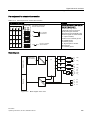
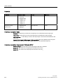
Commissioning guideline
2.9 Configuring the Example
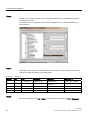
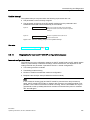
Step 3
Double-click on the first module in the configuration table (slot 4: 8 DI NAMUR) and select
the "Parameters" tab.
At channels 0 and 1 change the sensor type to "NAMUR sensor." Select "disabled" for all
other channels.
Figure 2-8
Disabling ET 200iSP Channels
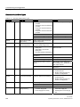
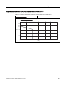
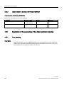
Step 4
Follow the same procedure as described in item 3 for each of the ET 200iSP modules, and
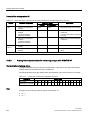
make the changes as outlined in the table below.
Table 2- 2
Changes
Module
Slot
1
4
2
5
3
6
4
7
5
8
Type
Channel 0
Channel 1
Channel 2- 7
8 x DI NAMUR
NAMUR sensor
NAMUR sensor
Sensor type: disabled
8 x DI NAMUR
NAMUR sensor
Sensor type: Channel
disabled
Sensor type: disabled
4 x DO
No change
No change
---
4 x DO
No change
No change
---
4 x DO
No change
No change
---
Step 5
Save the configuration with File > Save and download it to the CPU withPLC > Download.
36
ET 200iSP
Operating Instructions, 01/2010, A5E00247483-04
Commissioning guideline
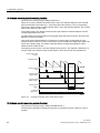
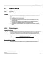
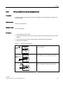
2.10 Programming the Sample Configuration
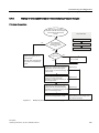
2.10
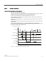
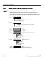
Programming the Sample Configuration
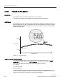
Principle of operation
The state of the sensors connected to inputs I512.0 , I513.0 and I514.0 is looked up and
analyzed. I512.0 increments an internal counter and I513.0 decrements it. Input I514.0
resets the counter to zero.
Depending on the counter value, outputs Q512.0, Q513.0 and Q514.0 are set or deleted.
Q512.0 is set when the count is 0. At a count < 3, Q514.0 is set and at ≥ 3, Q513.0 is set.
Programming
Change to the component view with View > Component View.
Open the following in succession: SIMATIC 400(1), CPU 416-3 DP, S7 Program(1) and
blocks until you can see the block OB1. Double-click on OB1 and confirm the dialog with OK.
Enter the following STL program:
STL
Explanation
A I 514.0
If button 514.0 is active,
R C 0
set counter to 0
A I 512.0
If BERO 512.0 is active,
CU C 0
increment by 1
A I 513.0
If BERO 513.0 is active,
CD C 0
decrement by 1
AN C 0
Is counter = 0 ?
= Q 512.0
YES, then output 512.0 is active
L C 0
Load counter in ACCU
L 3
Load 3 in ACCU
>=I
Is counter => 3 ?
= Q 513.0
YES, then output 513.0 is active
<I
Is counter < 3 ?
= Q 514.0
Yes, then output 514.0 is active
Save the program with File > Save and download it to the CPU withPLC > Download.
ET 200iSP
Operating Instructions, 01/2010, A5E00247483-04
37
Commissioning guideline
2.11 Putting the Example into Operation
2.11
Putting the Example into Operation
Commissioning
Turn on the power supply of the ET 200iSP.
Watch the status LEDs on the S7-400 and the ET 200iSP:
● CPU 416-3 DP is lit
RUN: lit
All other LEDs: off
● ET 200iSP
SF: off
BF: off
ON: lit
PS ON: lit
2.12
Evaluating the diagnostics
Evaluating the diagnostics
If an error occurs, OB82 is started. Evaluate the startup information in OB82.
Tip: Call SFC13 in OB82 and evaluate the diagnostic frame from the Chapter
Commissioning and Diagnostics (Page 133).
38
ET 200iSP
Operating Instructions, 01/2010, A5E00247483-04
Commissioning guideline
2.13 Removing and inserting of modules
2.13
Removing and inserting of modules
Removing and inserting digital electronics module 8 DI NAMUR
1. Remove the first of the three electronics modules 8 DI NAMUR from the terminal module
during operation.
2. Monitor the status LEDs on the IM 152:
– SF: lit -> diagnostic message exists.
– BF: off
– ON: lit
– PS ON: lit
Result: The ET 200iSP continues to operate problem-free.
3. Evaluate the diagnostic message:
Result:
– Station status 1 (byte 0): Bit 3 is set -> External diagnostics
– ID-related diagnostics: Bit 3 in byte 7 is set -> slot 4
– Module status: Byte 16.7 / 16.6: 11B -> no module
4. Re-insert the unplugged electronics module in the terminal module.
Result:
– Status LEDs IM 152:
SF: off
BF: off
ON: lit
PS ON: lit
– The diagnostic message is deleted.
ET 200iSP
Operating Instructions, 01/2010, A5E00247483-04
39
Commissioning guideline
2.14 Wire break of NAMUR encoder on digital input module
2.14
Wire break of NAMUR encoder on digital input module
Procedure
1. Remove the wire from terminal 1 of the first 8 DI NAMUR electronic module.
2. Observe the status LEDs.
– Status LED IM 152:
SF: on -> diagnostic message exists
– Status LEDs electronic module 8 DI NAMUR:
SF: on -> diagnostic message exists
3: off/on
3. Evaluate the diagnostic message
Result:
– Station status 1 (byte 0): Bit 3 is set -> External diagnostics
– ID-related diagnostics: Byte 7.3 is set -> slot 4
– Channel-related diagnostics:
Byte 25: 10000011B -> slot 4
Byte 26: 01000000B -> channel 0
Byte 27: 00110B -> wire break
4. Connect the wire to the BERO again in terminal 1 and evaluate the diagnostics again:
– Status LED IM 152
SF: off
– Status LEDs electronic module 8 DI NAMUR:
SF: off
3: off/on
– The diagnostic message is deleted.
40
ET 200iSP
Operating Instructions, 01/2010, A5E00247483-04
3
Configuration options
3.1
Modular system
Modular system
With the ET 200iSP, modular means: You can adapt the configuration to your application
with 4 and 8 channel electronic modules.
Example
The following schematic shows an example of a possible configuration of the ET 200iSP
distributed I/O station:
6ZLWFKVHQVRUV
1$085VHQVRU
&RXQWSXOVHIUHTXHQF\
9DOYHVUHOD\V
ZLUHWUDQVGXFHU
P$
5HVLVWDQFHWKHUPRPHWHU
7KHUPRFRXSOHV
/RDGVDWFXUUHQWRXWSXW
+$57ILHOGGHYLFHV
Figure 3-1
Example of an ET 200iSP configuration
ET 200iSP
Operating Instructions, 01/2010, A5E00247483-04
41
Configuration options
3.2 Electronics modules suitable for your application
3.2
Electronics modules suitable for your application
Which electronic module does what?
In the following table, you will find a guide to the applications of the electronic modules of the
ET 200iSP distributed I/O station.
Table 3- 1
Electronic modules to suit your application
Application
Evaluating NAMUR sensors
Electronic modules
8 input channels
8 DI NAMUR
Evaluation of connected, unconnected mechanical contacts
Acquisition of counted pulses
Measuring frequencies
Switching solenoid valves, d.c. relays, indicator lamps, actuators 4 output channels
Deactivation via High
active, intrinsically safe
switching signal
4 DO DC23.1V/20mA
SHUT DOWN "H"
4 DO DC17.4V/27mA
SHUT DOWN "H"
4 DO DC17.4V/40mA
SHUT DOWN "H"
4 output channels
Deactivation via Low
active, intrinsically safe
switching signal
4 DO DC23.1V/20mA
SHUT DOWN "L"
4 DO DC17.4V/27mA
SHUT DOWN "L"
4 DO DC17.4V/40mA
SHUT DOWN "L"
2 output channels
2 DO Relay UC60V/2A
up to 60 VDC/up to 60
VAC
Measuring currents with two-wire measuring transducers
(standard applications)
4 input channels
4 AI I 2WIRE HART
Input range
Measuring currents with HART field devices (2-wire transducers) 4 to 20 mA
HART communication
HART
Measuring currents with 4-wire measuring transducers (standard 4 input channels
applications)
Input ranges
Measuring currents with HART field devices (4-wire transducers) 0 to 20 mA
HART communication
4 to 20 mA
HART
4 AI I 4WIRE HART
Measuring temperatures with resistance thermometers
4 input channels
4 AI RTD
Measuring resistance
Input ranges
Pt 100, Ni 100
600 ohms
42
ET 200iSP
Operating Instructions, 01/2010, A5E00247483-04
Configuration options
3.3 Electronics modules suitable for the terminal modules
Application
Electronic modules
4 AI TC
Measuring temperatures with thermocouples
4 input channels
Measuring thermal e.m.f.
Input ranges
±80 mV
Type J, K, T, U, E, L,
N, R, S, B
Output of currents with HART field devices
4 output channels
HART communication
Output ranges
0 mA to 20 mA
4 mA to 20 mA
HART
Outputting of currents
3.3
4 AO I HART
Electronics modules suitable for the terminal modules
Selecting the terminal modules
The table below provides
● an aid for selecting individual terminal modules and
● a slot assignment on the terminal modules.
Table 3- 2
Modules and terminal modules
Modules
Order No. 6ES7193-
Terminal modules
TM-PS-A
TM-PS-A UC
TM-PS-B
TM-PS-B UC
7DA10-0AA0 7DA20-0AA0
TM-IM/IM
7AB00-0AA0
7DB10-0AA0 7DB20-0AA0
Power supply PS 24
VDC (up to product
version 5)
x
Power supply PS 24
VDC (up to product
version 6)
x
Power supply PS
120/230 VAC
TM-IM/EM 60S
TM-IM/EM 60C
TMEM/EM 60S
7AA00-0AA0
7CA00-0AA0
7AA10-0AA0
7CA10-0AA0
TMRM/RM 60S
TMEM/EM 60C
7CB00-0AA0
x
x
Interface module IM 152
x
x
x
8 DI NAMUR
x
x
x
4 DO 23.1 VDC/20mA
x
x
x
4 DO 17.4 VDC/27mA
x
x
x
4 DO 17.4 VDC/40mA
x
x
x
x
x
x
2 DO Relay UC60V/2A
4 AI I 2WIRE HART
ET 200iSP
Operating Instructions, 01/2010, A5E00247483-04
x
x
43
Configuration options
3.4 Configuration Options in Zones
Modules
Terminal modules
4 AI I 4WIRE HART
x
x
x
4 AI RTD
x
x
x
4 AI TC
x
x
x
4 AO I HART
x
x
x
Reserve module
x
x
x
WATCHDOG
x
x
x
1
x1
x1
product version 3 or higher of the reserve module
3.4
Configuration Options in Zones
General rules
Regardless of the configuration of the ET 200iSP in hazardous areas or in the safe area, the
following rules apply:
The ET 200iSP distributed IO station can only be operated on the intrinsically safe
PROFIBUS RS 485-IS:
1. An RS 485-IS coupler (field bus isolating transformer) is always required
2. Identification of PROFIBUS DP as Ex i (not only for potentially explosive areas)
3. Marking of the cables/wires to the actuators and sensors as EEx i (for example, using the
color light blue).
WARNING
All devices connected to PROFIBUS RS 485-IS must be intrinsically safe.
Do not connect voltage measuring devices, oscillographs, and bus testers to
PROFIBUS RS 485-IS.
Rules for configuring the ET 200iSP in Zone 1:
If you use the ET 200iSP in zone 1, you must adhere to the following rules:
1. Installation of ET 200iSP in a metallic enclosure (see Chapter "Installation rules
(Page 81)") with type of protection Ex e (increased safety). (see Appendix "Order
numbers (Page 347)").
2. Isolation of PROFIBUS DP by means of RS 485-IS coupler (see Appendix "Order
Numbers (Page 347)"). The RS 485-IS Coupler ensures protection class Ex i of
PROFIBUS DP in potentially explosive areas. You can install the RS 485-IS Coupler in
zone 2 potentially explosive areas or in safe areas.
3. You can use standard PROFIBUS DP cables (see Appendix "Order Numbers
(Page 347)") in potentially explosive areas. You must, however, mark these as "Ex i bus
cable" (for example, with a blue band/blue shrink-on sleeve at the ends or mark the cable
with a blue color).
44
ET 200iSP
Operating Instructions, 01/2010, A5E00247483-04
Configuration options
3.4 Configuration Options in Zones
4. Connect the PROFIBUS RS 485-IS bus cable to the IM 152 using the PROFIBUS RS
485-IS connector (see Appendix "Order numbers (Page 347)").
5. Terminate the PROFIBUS RS 485-IS with the PROFIBUS RS 485-IS connector: (see
Appendix "Order Numbers (Page 347)"). The transmission rate determines the maximum
length of PROFIBUS RS 485-IS (refer to product information RS 485-IS coupler
(http://support.automation.siemens.com/WW/view/en/29306413)).
56,6&RXSOHU
6DIHDUHD
352),%86'3EXVOLQH
352),%86
56,6
+D]DUGRXVDUHD=RQH
(QFORVXUHGHJUHHRISURWHFWLRQ([H
(QFORVXUHGHJUHHRISURWHFWLRQ([H
(7L63
%XVFRQQHFWRU0%DXG
Figure 3-2
(7L63
%XVFRQQHFWRUZLWKLQWHJUDWHGWHUPLQDWLQJUHVLVWRU
Configuration Options for the ET 200iSP in Zone 1
Rules for configuring the ET 200iSP in Zone 21:
If you use the ET 200iSP in zone 21, you must adhere to the following rules:
1. Install the ET 200iSP in a metallic, dust-proof (certified) enclosure (refer to Chapter
"Rules for installation (Page 81)") with at least degree of protection IP 6x (according to
guideline 94/9/EU for category 2D). Additional requirements (such as surface
temperature) can be found in the certification document for the specific enclosure (refer to
appendix "Order numbers (Page 347)").
2. See points 2 to 5: Rules for Configuring the ET 200iSP in Zone 1
ET 200iSP
Operating Instructions, 01/2010, A5E00247483-04
45
Configuration options
3.4 Configuration Options in Zones
Rules for configuring the ET 200iSP in Zone 2:
If you use the ET 200iSP in zone 2, you must adhere to the following rules:
1. Installation of the ET 200iSP in a metallic enclosure (refer to Chapter "Rules for
installation (Page 81)") with at least degree of protection IP 54. The enclosure must have
a manufacturer certification for zone 2 (complying with EN 60079-15: Protection from
mechanical damage; degree of protection IP 54; avoidance of ignition due to electrostatic
charge). (see Appendix "Order Numbers (Page 347)").
2. See points 2 to 5: Rules for Configuring the ET 200iSP in Zone 1
Rules for Configuring the ET 200iSP in Zone 22:
If you use the ET 200iSP in zone 22, you must adhere to the following rules:
1. Install the ET 200iSP in a metallic, dust-proof enclosure (refer to Chapter "Rules for
installation (Page 81)") with at least degree of protection IP 5x (according to directive
94/9/EU for category 3D). Additional requirements (such as surface temperature) can be
found in the certification document for the specific enclosure (refer to appendix "Order
numbers (Page 347)").
2. See points 2 to 5: Rules for Configuring the ET 200iSP in Zone 1
DANGER
If the Zone 22 potentially explosive area is subject to conductive dust (for example,
metal dust), the rules for zone 21 apply.
Rules for configuring the ET 200iSP in the safe area:
If you use the ET 200iSP in a safe area, you must adhere to the following rules:
1. Installation of the ET 200iSP in a metallic enclosure with degree of protection IP 20.
2. See points 2, 4 and 5: Rules for Configuring the ET 200iSP in Zone 1
46
ET 200iSP
Operating Instructions, 01/2010, A5E00247483-04
Configuration options
3.4 Configuration Options in Zones
Rules for the configuration of sensors, actuators, and HART field devices in hazardous areas.
The verification of intrinsic safety for each field circuit must be made according to the
regulations stipulated by the relevant standards for configuration, selection and installation.
A simple, intrinsically safe circuit results from attaching a sensor, actuator or HART field
device to an input or output of an electronic module.
The following table describes the conditions for checking the maximum safe values for a
simple, intrinsically safe circuit:
Table 3- 3
Rules for configuration
Relevant Standard / Conditions for Electrical Parameters
Usable Sensors and Actuators
Standard: EN 60 079-14
The maximum safe values of the sensors and actuators
must be adapted to the maximum values of the electronic
modules. You will find these maximum values
in the Ex certification of the sensors and actuators
in the technical specifications of the electronic modules
of the ET 200iSP
The following applies to the electrical parameters:
U0 ≤Ui
I0≤II
P0≤Pi
C0≥Ci+Ccable
L0≥Li+Lcable
ET 200iSP
modules
8
,
3
&
/
Sensors
Actuators
HART field devices
Ccable max. capacitance wire/cable
Lcable max. inductance
&&DEOH Ui max. input voltage
/&DEOH Ii max. input current
Pi max. input power
8L
,L
3L
&L
/L
ET 200iSP
Operating Instructions, 01/2010, A5E00247483-04
U0 max. output voltage
I0 max. output current
P0 max. output power
C0 max. external capacity
L0 max. external inductance
Ci max. inner capacitance
Li max. inner inductance
47
Configuration options
3.5 Use of the ET 200iSP in category M2 of equipment-group I (mining)
Safety information
Note
Always configure the system in accordance with EN 60 079-14 directives.
WARNING
Connecting an intrinsically safe sensor, actuator, or HART field device to the input/output of
an electronic module must produce an intrinsically safe circuit! Always check for resultant
safety values when you select the sensors, actuators and HART field devices for an
electronic module.
See also
Operating the ET200iSP with older CPUs (Page 61)
Order numbers (Page 347)
3.5
Use of the ET 200iSP in category M2 of equipment-group I (mining)
Requirements
The following conditions must be fulfilled if the ET 200iSP is used in device group I
(underground mining operations and their overground systems) Category M2:
CAUTION
To avoid ignitable sparks, the power supply PS and the mounting rail of the ET 200iSP
must be packaged in shock-proof packaging for transportation and storage (e.g. for
servicing) and immediately removed from the potentially explosive area.
The enclosure in which the ET 200iSP is installed must be approved for device group I,
category M2.
Observe all other requirements concerning use of the ET 200iSP in the potentially
explosive area.
48
ET 200iSP
Operating Instructions, 01/2010, A5E00247483-04
Configuration options
3.6 Restricted Number of Connectable Electronics Modules
3.6
Restricted Number of Connectable Electronics Modules
Number of electronic modules
Each ET 200iSP station consists of a maximum of 32 electronic modules. These include
digital and analog electronic modules.
The actual number of electronic modules can be limited by the effective current output of the
power supply PS. It is not permitted to violate this limit value (maximum permitted current).
In the following situation, unrestricted use and combination of the modules in the ET 200iSP
are possible:
ET 200iSP up to 16 electronic modules
Verify any configuration containing a higher number of electronic modules (up to 32), or an
EM 4 DO 17.4 VDC/40mA, with the help of the calculation table (see below).
Calculation table
With the calculation table, you can check the operational current consumption of the ET
200iSP.
Note
ET 200iSP always conforms with safety-relevant current consumption limits (limit value < 15
A, see EC Prototype Test Certification KEMA 04ATEX2242). With all configurations, the
number of modules is restricted only by the effective current output (refer to following table)
or the maximum number of modules (32).
Structure
Power supply
Maximum operational current
output
Normal operation
PS 24 VDC1
5A
PS 120/230 VAC2
Redundancy
1
2
3
PS 24 VDC1
PS 24 VDC1
PS 120/230 VAC2
PS 120/230 VAC2
PS 24 VDC3
PS 120/230 VAC2
Product version 3 and higher:
Maximum effective current output 5A at 170 VAC to 264 VAC (up to 60°C) or at 85 VAC to 132
VAC (up to 50°C). Refer to technical specifications in the Chapter Power Supply PS 120/230 VAC.
Product version 5 and higher:
ET 200iSP
Operating Instructions, 01/2010, A5E00247483-04
49
Configuration options
3.6 Restricted Number of Connectable Electronics Modules
Procedure
Check the operational current consumption of your ET 200iSP configuration. The limit value
specified in the table column =operational current consumption in mA must not be exceeded.
1. Multiply the operational current per module by the number of modules, then enter the
values in the = operational current consumption in mA column.
2. Add all modules and enter the value in the Total Modules box (maximum of 32 electronic
modules).
3. Add the operational current consumption and enter the value in the Total Current
Consumption box.
4. Compare the calculated totals with the specified limits.
Table 3- 4
Calculation table for current output
Electronic modules
x Number
of modules
Operational
current per
module in mA
= Operational current
consumption in mA
Power supply PS 24 VDC/
PS 120/230 VAC
x
15 mA
=
IM 152
x
30 mA
=
8 DI NAMUR
x
80 mA
=
4 DO DC23.1V/20mA SHUT DOWN "H"
x
290 mA
=
4 DO DC17.4V/27mA SHUT DOWN "H"
x
260 mA
=
4 DO DC17.4V/40mA SHUT DOWN "H"
x
380 mA
=
4 DO DC23.1V/20mA SHUT DOWN "L"
x
290 mA
=
4 DO DC17.4V/27mA SHUT DOWN "L"
x
260 mA
=
4 DO DC17.4V/40mA SHUT DOWN "L"
x
380 mA
=
2 DO Relay UC60V/2A
x
100 mA
=
4 AI I 2WIRE HART
x
280 mA
=
4 AI I 4WIRE HART
x
27 mA
=
4 AI RTD
x
19 mA
=
4 AI TC
x
17 mA
=
4 AO I HART
x
295 mA
=
Reserved
x
---
---
WATCHDOG
x
2 mA x DO **
Total
Modules
Total Current
Consumption
=
=
max. 32*
< max. effective current
output***
* Without power supply PS and IM 152
** Operational current consumption of WATCHDOG module = 2 mA x number of connected digital
output modules
*** Refer to above table for values
50
ET 200iSP
Operating Instructions, 01/2010, A5E00247483-04
Configuration options
3.6 Restricted Number of Connectable Electronics Modules
Example
An ET 200iSP consists, for example, of the following electronic modules:
● 1 power supply module PS 24 VDC
● 5 x 8 DI NAMUR modules,
● 5 modules 4 DO DC17.4V/27mA SHUT DOWN "H"
● 2 modules 4 DO DC23.1V/20mA SHUT DOWN "H"
● 3 x 4 DI I 2 WIRE HART modules
● 5 x 4 DI I 4WIRE HART modules
● 5 x 4 DI RTD modules
● 4 x 4 DI TC modules
● 3 x 4 AO I HART modules
With 32 electronic modules, the current consumption (< 5000 mA) must be checked:
Table 3- 5
Calculation table for current output
Electronic modules
x Number
of modules
Operational
current per
module in mA
= Operational current
consumption in mA
Power supply PS 24 VDC/
PS 120/230 VAC
x1
15 mA
= 15 mA
IM 152
x1
30 mA
= 30 mA
8 DI NAMUR
x5
80 mA
= 400 mA
4 DO DC23.1V/20mA SHUT DOWN "H"
x2
290 mA
= 580 mA
4 DO DC17.4V/27mA SHUT DOWN "H"
x5
260 mA
= 1300 mA
4 DO DC17.4V/40mA SHUT DOWN "H"
x ---
380 mA
= ---
4 DO DC23.1V/20mA SHUT DOWN "L"
x ---
290 mA
= ---
4 DO DC17.4V/27mA SHUT DOWN "L"
x ---
260 mA
= ---
4 DO DC17.4V/40mA SHUT DOWN "L"
x ---
380 mA
= ---
2 DO Relay UC60V/2A
x ---
100 mA
= ---
4 AI I 2WIRE HART
x3
280 mA
= 840 mA
4 AI I 4WIRE HART
x5
27 mA
= 135 mA
4 AI RTD
x5
19 mA
= 95 mA
4 AI TC
x4
17 mA
= 68 mA
4 AO I HART
x3
295 mA
= 885 mA
Reserved
x ---
---
---
WATCHDOG
x ---
2 mA x DO **
= ---
Total
Modules
Total Current
Consumption
=
= 4348 mA
max. 32*
< 5000 mA
* Without power supply PS and IM 152
** Operational current consumption of WATCHDOG module = 2 mA x number of connected digital
output modules
ET 200iSP
Operating Instructions, 01/2010, A5E00247483-04
51
Configuration options
3.7 Maximum configuration of the ET 200iSP
Note
The limit values are adhered to in the example.
Result: ET 200iSP station can be operated with this configuration.
Calculation of ET 200iSP power loss
You can calculate the power loss of the ET 200iSP using the following formula:
PVtotal = x*5W + 1.2*∑PV_Type_I/O
Explanation:
x*5W = basic power loss of power supply (x = 1 for standard configuration, x = 2 for
redundant configuration or increase in performance )
1,2*∑PV_Type_I/O = typical power loss of input and output modules, including the resulting PV in
the power supply.
3.7
Maximum configuration of the ET 200iSP
Number of ET 200iSP Stations
You may operate up to 31 ET 200iSP stations on one segment of
PROFIBUS RS 485-IS (via RS 485-IS Coupler).
Power consumption of ET 200iSP with full configuration
Refer to technical specifications Power supply PS 24 VDC (Page 223) and technical
specifications Power supply PS 120/230 VAC (Page 226).
Width of ET 200iSP
The maximum configuration width ET 200iSP (power supply + interface module + 32
electronic modules + terminating module) is:
● 1.095 m (with one power supply and one IM 152)
● 1.185 m (with two power supplies and two IM 152)
Address space
The interface module supports maximum 244 input and 244 output bytes. There are DP
masters that do not control the entire address space.
52
ET 200iSP
Operating Instructions, 01/2010, A5E00247483-04
Configuration options
3.8 Power Supply of the ET 200iSP
3.8
Power Supply of the ET 200iSP
Power supply PS
Connect the voltage supply of ET 200iSP to terminal module TM-PS-A/ TM-PS-A UC of the
power supply. The power supply provides the required output voltages for the ET 200iSP.
The output voltages are electrically isolated from the supply voltage.
● Power supply PS 24 VDC: 24 VDC
● Power supply PS 120/230 VAC: 85 - 264 VAC
2XWSXWYROWDJHV
6XSSO\YROWDJH9'&
9$&9$&
3RZHUEXV
,0
*URXQGLQJEXVEDU3$
Figure 3-3
%DFNSODQHEXV
Power supply PS
Note
Protect the power supply with a 6 A automatic circuit breakers and tripping characteristic
C (for each ET 200iSP station).
3.9
Direct data exchange
Prerequisites
The ET 200iSP can be used as publisher for direct data exchange (cross communication).
This requires no configuration.
The DP master you are using must, of course, also support direct data exchange. You will
find information on this in the description of the DP master.
Principle of operation
Direct data exchange is characterized by PROFIBUS DP nodes which "listen" on the bus
and know which data a DP slave returns to its DP master. With this mechanism, the
"listener" (recipient) can access changes to the input data of remote DP slaves directly.
During configuration in STEP 7, you use the peripheral input addresses to specify the
address area of the recipient in which the required data of the publisher will be read.
ET 200iSP
Operating Instructions, 01/2010, A5E00247483-04
53
Configuration options
3.10 Identification data I&M
Example
The schematic below illustrates the direct data exchange "relationships" that you can
configure with an ET 200iSP as publisher and which nodes can "listen in" as potential
recipients.
'3PDVWHUV\VWHP
&38[
&38b[DV
'3PDVWHUb
'3PDVWHUV\VWHP
&38b[DV
'3PDVWHUb
352),%8656,6
'3VODYH
(7L63
(7L63
Figure 3-4
3.10
(7L63
&38b[DV
'3VODYH
Example of Direct Data Exchange
Identification data I&M
Properties
I data: Information about the module that is normally printed on the enclosure of the module.
I data is read-only.
M data: System-specific information such as the installation location and date. M data is
generated during configuration and written to the module.
Identification data (I&M) this information stored on a module that supports you when
● Troubleshooting in a system
● Checking the system configuration
● Locating hardware changes in a system
Reading and writing the identification data with STEP 7
HW Config shows the I&M in the "Module status - IM 152" and "Properties - DP Slave" tabs.
For information, refer to the STEP 7 Online Help.
Reading and writing the I&M with SIMATIC PDM
With SIMATIC PDM you can read the parameters and I&M by choosing the File > Complete
Download to PG/PC menu command and write them by choosing the Device > Complete
Download to Device menu command.
54
ET 200iSP
Operating Instructions, 01/2010, A5E00247483-04
Configuration options
3.10 Identification data I&M
Reading the I&M with SFB52
The standard function block SFB 52 can be used to read the data records of a DP slave. To
read the I&M, download the data records 231 to 234 (see table below).
Note
At present, the I&M data record objects cannot be read or written to by means of data record
DS 255.
Identification data I&M
Table 3- 6
Identification data I&M
I&M
Access
Default
Explanation
I data 0: Index 1 (data record 231)
MANUFACTOR_ID
read (2 bytes)
2A hex (=42 dec)
The name of the manufacturer is stored
here. (42 dec = SIEMENS AG)
ORDER_ID
read (20 bytes)
Dependent on the
module
Order number of the module
SERIAL_NUMBER
read (16 bytes)
Depends on the product
version
The serial number of the module is stored
here. This makes unique identification of
the module possible.
HW_REVISION
read (2 bytes)
Depends on the product
version
This provides information on the product
version of the module. This is
incremented when the product version
and/or the firmware of the module
changes.
SW_REVISION
read (4 bytes)
Depends on the product
version
Provides information on the firmware
version of the module. If the firmware
version is incremented, then the product
version (HW_REVISION) of the module is
incremented as well.
REVISIONS_COUNTER
read (2 bytes)
---
Provides information on the assigned
changes on the module. After each
change, the REVISION_ COUNTER is
incremented.
PROFILE_ID1
read (2 bytes)
Not applicable
PROFILE_SPECIFIC_TYPE1
read (2 bytes)
Not applicable
IM_VERSION1
read (2 bytes)
10 hex
Provides information on the version of the
I&M (10 hex = Version 1.0).
IM_SUPPORTED1
read (2 bytes)
3E hex
Provides information on available I&M
data (index 1 to 4).
M data 1: Index 2 (data record 232)
TAG_FUNCTION
read / write (32
bytes)
---
Enter a system-wide unique identifier for
the module here.
TAG_LOCATION
read / write (22
bytes)
---
Enter the installation location of the
module here.
ET 200iSP
Operating Instructions, 01/2010, A5E00247483-04
55
Configuration options
3.11 Redundancy of the Power Supply
I&M
Access
M data 2: Index 3 (data record 233)
Default
Explanation
DEVICE_INSTALL_ DATE
---
Enter the installation date of the module
here.
---
Enter a comment on the module here.
read / write (16
bytes)
M data 3: Index 4 (data record 234)
DESCRIPTOR
1
read / write (54
bytes)
The display of this I&M depends on the engineering software.
See also
Project Engineering with GSD File and SIMATIC PDM (Page 138)
3.11
Redundancy of the Power Supply
Properties
With the ET 200iSP, you can configure a redundant power supply PS. When one power
supply PS fails, the system fails over to the second power supply PS without interruption.
Requirements
● Terminal module TM-PS-A/ TM-PS-A UC
● Terminal module TM-PS-B/ TM-PS-B UC
● 2 x Power Supply PS
● IM 152 (V2.0 and higher)
Combination options of the power supply PS with TM-PS-A and TM-PS-B
TM-PS-A
TM-PS-B
PS 24 VDC*
PS 24 VDC*
* All product versions
Combination options of the power supply PS with TM-PS-A UC and TM-PS-B UC
TM-PS-A UC
TM-PS-B UC
PS 24 VDC*
PS 24 VDC*
PS 120/230 VAC**
PS 120/230 VAC**
PS 24 VDC*
PS 120/230 VAC**
* Product version 6 and higher
** Maximum output current, refer to technical specifications in the Chapter Power Supply PS 120/230
VAC
56
ET 200iSP
Operating Instructions, 01/2010, A5E00247483-04
Configuration options
3.11 Redundancy of the Power Supply
Combination options of the power supply PS with TM-PS-A and TM-PS-B UC or TM-PS-A UC and
TM-PS-B
TM-PS-A
TM-PS-B UC
PS 24 VDC*
PS 120/230 VAC**
TM-PS-A UC
TM-PS-B
PS 120/230 VAC**
PS 24 VDC*
* Product version 5 and higher
** Maximum output current, refer to technical specifications in the Chapter Power Supply PS 120/230
VAC
Installation and Wiring
1. Begin the installation with the TM-PS-A/ TM-PS-A UC.
2. Install the TM-PS-B/ TM-PS-B UC to the right of the TM-PS-A/ TM-PS-A UC.
3. Now complete the ET 200iSP configuration.
4. Connect a separate power supply to each TM.
5. Finally, fit the TMs with Power Supply PS 1 and PS 2.
7036%7036%8&
7036$7036$8&
36 36
$&
'&
$&
'&
Figure 3-5
Redundancy of the Power Supply (example)
Parameter Assignment
Only those parameters that are relevant for the redundancy of the power supply are
explained below. These are part of the parameters of the IM 152 interface module.
Table 3- 7
Parameters for redundancy of the Power Supply PS
Parameters
Setting
Self-diagnostics
enabled
---
Redundant Power
Supply diagnostics
Redundant Power Supply
Diagnostics in the event of failure of
Power Supply PS 1 or PS 2
ET 200iSP
Operating Instructions, 01/2010, A5E00247483-04
Description
57
Configuration options
3.12 System configuration in RUN (CiR)
See also
Power supply PS 120/230 VAC (Page 226)
Power supply PS 24 VDC (Page 223)
3.12
System configuration in RUN (CiR)
3.12.1
System modification in a non-redundant system
Properties
There are plants that must not be closed down while they are running. This may be due to
the complexity of the automated process or because of the costs involved in restarting. A
modification or removal of system components may nonetheless be necessary.
Certain system configurations and parameters can be modified in RUN by means of the CiR
function. To make the modifications, the process is halted for a brief time. The process
inputs retain their last value during this time period.
The configuration of the ET 200iSP can be modified during operation with CiR.
You will find a detailed description of this function and the settings for it in the function
manual Modifying the System during Operation via CiR
(http://support.automation.siemens.com/WW/view/en/14044916).
What points should you note when planning the ET 200iSP stations?
● Construct the ET 200iSP station entirely using terminal modules and a terminating
module.
● Add components to the ET 200iSP outwards from the interface module, starting with the
necessary electronic modules. Fill the remaining slots with the reserve modules as far as
the terminating module. All the reserve modules must be inserted and there must be no
gaps.
● You must not configure these reserve modules.
Rules for making changes to the system while it is in use
● Replace the reserve modules with the planned electronic modules. Start with the first
reserve module in the lowest slot (to the right of the last electronic module). This may
create a gap, i.e. only replace a reserve module with the electronic module.
● If you have fitted a slot cover on the last free slot, it is not expandable.
● Note that terminal modules TM-RM/RM are required for electronic modules 2DO Relay
UC60V/2A.
58
ET 200iSP
Operating Instructions, 01/2010, A5E00247483-04
Configuration options
3.12 System configuration in RUN (CiR)
Changing the parameter settings in RUN mode
Note the operator steps used for reassigning paramters in the function manual Modifying the
system during operation via CiR
(http://support.automation.siemens.com/WW/view/en/14044916).
Reaction of the I/O to parameter reassignment in RUN
When changing the parameter settings for certain modules (see table), make sure that there
is no diagnostic event pending for this module (for example wire break) prior to changing the
settings otherwise diagnostic events exiting the state may no longer be signaled in some
situations. The effect is that the LEDs on the CPU, IM, or module stay lit even though the
reconfigured module is operating properly. If, this situation nevertheless arises, the module
must be removed and reinserted.
Table 3- 8
Behavior of the inputs/outputs
Electronic module
Behavior of the inputs/outputs
Points to note when changing
parameter settings
8 DI NAMUR
They return the process value
that applied before the
parameters were set. Inputs not
affected return their last valid
value (with value status).
SF LED is lit.
4 DO DC23.1V/20mA
SHUT DOWN "H"/ "L"
4 DO DC17.4V/27mA
SHUT DOWN "H"/ "L"
4 DO DC17.4V/40mA
SHUT DOWN "H"/ "L"
They output the output value
that applied before the
parameters were set.
Unaffected outputs return their
last valid value.
2 DO Relay UC60V/2A
4 AI I 2WIRE HART
4 AI I 4WIRE HART
4 AI RTD
4 AI TC
4 AO I HART
ET 200iSP
Operating Instructions, 01/2010, A5E00247483-04
They return the process value
that applied before the
parameters were set. Inputs not
affected return their last valid
value.
If a diagnostic event was
reported before you started to
reassign parameters, the SF
LEDs (on the CPU, IM or
module) may be lit even though
the module is operating properly
and the diagnostic event has
been cleared.
Only make new parameters
settings when there is no
diagnostic event pending, or
Remove and insert module.
They output the output value
that applied before the
parameters were set.
Unaffected outputs return their
last valid value.
59
Configuration options
3.12 System configuration in RUN (CiR)
3.12.2
System modification in a redundant system
Properties
Information on using this function in the redundant structure can be found in the S7-400H
automation system, fault-tolerance systems
(http://support.automation.siemens.com/WW/view/en/1186523) manual and in the online
help for the H option package for STEP 7.
Requirements
● as of STEP 7 V5.3 SP2 with HW update 0042 (version V3.0)
● PCS7 will be released with the next service packs for PCS7 V6.1, V7.0 and V7.1.
What points should you note when planning the ET 200iSP stations?
● Construct the ET 200iSP station entirely using terminal modules and a terminating
module.
● Add components to the ET 200iSP with the necessary electronic modules. Fill the
remaining slots with the reserve modules. All the reserve modules must be inserted and
there must be no gaps.
● You do not have to configure reserve modules.
Rules for making changes to the system while it is in use
● If you are modifying the real hardware configuration, there may be only one gap each.
When removing the electronic modules, replace the electronics modules by reserve
modules; when adding electronic modules, replace the installed reserve modules with
electronic modules.
● If you have fitted a slot cover on the last free slot, it is not expandable.
● Note that terminal modules TM-RM/RM are required for electronic modules 2DO Relay
UC60V/2A.
Example: Replacement of configured electronic modules
1. Replace the electronic modules or reserve modules with gaps in the configuration (HW
config).
2. Execute the Save and Compile menu command.
3. Download the station configuration to the H station in RUN mode.
4. Change the real hardware configuration: Remove and install one module at a time (for
example, remove slot 5 --> install slot 5). Note: two empty slots are not permitted.
5. Replace the gaps in the configuration (HW config) with the new electronic modules.
6. Execute the Save and Compile menu command.
7. Download the station configuration to the H station in RUN mode.
Result
The system modification was successfully completed.
60
ET 200iSP
Operating Instructions, 01/2010, A5E00247483-04
Configuration options
3.13 Operating the ET200iSP with older CPUs
3.13
Operating the ET200iSP with older CPUs
Operating the ET200iSP with older CPUs
The following CPUs cannot be operated in DPV1 mode. The ET 200iSP must be integrated
via the GSD file for projects with these CPUs. Parameters are to be assigned with SIMATIC
PDM.
Table 3- 9
Operating the ET200iSP with older CPUs
CPU
Order Number
HW Version FW Version
CPU 412-1
6ES7412-1XF03-0AB0
8
V3.1.3
CPU 412-2
6ES7412-2XG00-0AB0
8
V3.1.3
CPU 413-1
6ES7413 1XG02-0AB0
9
CPU 413-2
6ES7413 2XG02-0AB0
9
CPU 414-1
6ES7414-1XG02-0AB0
9
CPU 414-2 with 128 kB
6ES7414-2XG03-0AB0
8
CPU 414-2 with 384 kB
6ES7414-2XJ01-0AB0
9
CPU 414-3
6ES7414-3XJ00-0AB0
8
V3.1.3
CPU 414-4H
6ES7414-4HJ00-0AB0
1
V3.1.3
CPU 416-1
6ES7416-1XJ02-0AB0
9
CPU 416-2 with 800 kB
6ES7416-2XK02-0AB0
8
V3.1.3
CPU 416F-2
6ES7416-2FK02-0AB0
2
V3.1.3
CPU 416-2 mit 1,6MB
6ES7416-2XL01-0AB0
9
CPU 416-3
6ES7416-3XL00-0AB0
8
V3.1.3
CPU 417-4
6ES7417-4XL00-0AB0
6
V3.1.3
CPU 417-4H
6ES7417-4HL01-0AB0
1
V3.1.3
Sync module
6ES7960-1AA00-0XA0
3
CPU 416-2 DP ISA Lite
6ES7616-2PG01-0AB4
1
CPU 416-2 DP ISA
6ES7616-2PK01-0AB4
2
CPU 412-2 DP PCI
6ES7612-2QH00-0AB4
1
V3.1.0
CPU 416-2 DP PCI
6ES7616-2QL00-0AB4
1
V3.1.0
ET 200iSP
Operating Instructions, 01/2010, A5E00247483-04
V3.1.3
61
Configuration options
3.14 Year of Production of the Module
3.14
Year of Production of the Module
Year of production
The year of production is included in the serial number (4th position). The serial number is
on the type plate.
([DPSOHRIDVHULDOQXPEHU
6 9 36 6
7
8
9
:
;
$
%
&
'
Figure 3-6
'LJLW
6HULDOQXPEHU
<HDURISURGXFWLRQ
Year of production
3.15
Time stamping
3.15.1
Fundamentals of Time Stamping
Properties
Time stamping is possible with the IM 152
● in customer applications using FB 62 (FB TIMESTMP)
(see also the STEP 7 Online Help).
● with the PCS 7 system solution accurate to 20 ms
For a detailed description of the time sampling and the time-of-day synchronization,
consult the PCS 7 function manual "10 ms time stamping".
Principle of operation
A modified input signal is assigned a time stamp and stored in a buffer (data record). If time
stamped signals exists or a data record is full, a hardware interrupt is generated to the DP
master. The buffer is evaluated with "Read data record". Special messages are generated
for events that influence the time stamping (communication with the DP master interrupted,
frame failure of time master, ...).
62
ET 200iSP
Operating Instructions, 01/2010, A5E00247483-04
Configuration options
3.15 Time stamping
Parameter Assignment
With the parameter assignment you define which IM 152 user data will be monitored. For the
time stamping these are digital inputs that are monitoring for signal changes.
3.15.2
Parameters
Setting
Description
Time stamping
disabled
enabled
Activate the time staming for the
channels of the electronics module 8
DI NAMUR.
Edge evaluation
incoming event
rising edge
falling edge
Determine the type of signal change
that will be time-stamped.
Time stamps accurate to 20 ms
Introduction
The time stamping of binary signal changes is supported in the PCS 7 system by all
hardware and software components: from the ET 200iSP over the S7-400 right to the OS.
Prerequisites
● Set a synchronization interval of 20 ms for the master and ET 200iSP.
● For time stamping, you require the 8 DI NAMUR electronics module with the "8DI
NAMUR" configuration. Time stamping is not possible with any other configuration of the
8DI NAMUR electronics module.
How time stamping works
You can configure the monitoring of digital inputs for signal changes in HW Config. The
following can be monitored: "Signal entering/leaving state" (as "rising or falling edge"). The
IM 152 stamps these changed input signals with the current time of day and saves them as
message lists. A message list is a data record with a maximum of 20 messages about timestamped signal changes. The IM 152 can store up to 15 data records.
After a certain time and if messages exist or when a data record is full, the IM 152 triggers a
hardware interrupt on the DP master (S7-400). The CPU then reads the data record and
passes on the message lists to WinCC on an OS using the driver block FB90 "IM_DRV".
ET 200iSP
Operating Instructions, 01/2010, A5E00247483-04
63
Configuration options
3.15 Time stamping
Example of time stamping
7LPHVHQGHU
6,&/2&.
:LQ&&
2SHUDWRU6WDWLRQ26
SODQWYLVXDOL]DWLRQ
,QGXVWULDO(WKHUQHW
&3bತ'3
PDVWHU
6DXWRPDWLRQV\VWHP
56,6&RXSOHU
(7L63
&3
352),%86
Figure 3-7
'LJLWDOLQSXWV
Example of time stamping and edge evaluation
How time stamping functions in the redundant system
Both IM°152 save the messages of the time-stamped signals. After a changeover from the
active to the passive IM 152 the "new" active IM 152 can relay the current messages to
WinCC.
During the switch between the two IM 152 the signal changes are not time-stamped. In
WinCC you can recognize in which time span not time stamping occurred.
64
ET 200iSP
Operating Instructions, 01/2010, A5E00247483-04
Configuration options
3.15 Time stamping
Example of time stamping in redundant system
5HDOWLPH
WUDQVPLWWHU
6,&/2&.
:LQ&&
2SHUDWRU6WDWLRQ26
V\VWHPYLVXDOL]DWLRQ
,QGXVWULDO(WKHUQHW
(7,63
GLVWULEXWHG,2ZLWK[,0
(7,63
6+
DXWRPDWLRQ
V\VWHP
56,6&RXSOHU
5HGXQGDQW
'3PDVWHU
V\VWHPV
Figure 3-8
3.15.3
'LJLWDOLQSXWV
Sample configuration with 2 IM 152s for redundancy in an H-system
Time synchronization with a flexible time interval
Description
The synchronization interval can be set in the configuration tool.
The longer the synchronization interval is set, the lower the accuracy of the time stamping.
ET 200iSP
Operating Instructions, 01/2010, A5E00247483-04
65
Configuration options
3.16 Counting
3.16
Counting
3.16.1
Properties
Counting functions
The 8 DI NAMUR electronics module has configurable counting functions:
● 2 x 16-bit up counters (standard counting function) or
● 2 x 16-bit down counters (standard counting function) or
● 1 x 32-bit down counter (cascading counter function)
● Setting a setpoint with the POI
● GATE function
● You can configure the control signals of the counters:
– "2 Count/ 6DI NAMUR" configuration: Two counters are configured. The control
signals of the counters are stored in the POI (process output image).
– "2 Count/ 6 Control" configuration: Two counters are configured. The control signals of
the counters are stored in the POI (process output image). They are also controlled by
the digital inputs of the 8 DI NAMUR.
● You configure the counters of the 8 DI NAMUR electronic module and assign the
parameters in the engineering software, for example, HW Config.
66
ET 200iSP
Operating Instructions, 01/2010, A5E00247483-04
Configuration options
3.16 Counting
3.16.2
Principle of operation
16-bit up counters (standard counting function)
The counting range is always 0 to 65,535.
With each count pulse at the digital input, the count is incremented by 1. Once the count limit
is reached, the counter is reset to 0 and it counts up again from this value.
If there is counter overflow, the corresponding output is set in the PII.
A positive edge of the Reset output control signal resets the output in the PII. This does not
affect the current count value.
In 16-bit up counting operations, the system does not set any outputs in the POI. These are
always reset.
The positive edge of the Reset counter control signal sets the counter to 0 and resets the set
counter output.
The GATE control signal pauses the counting on a positive edge. Count pulses are
processed at the digital input again, but only at the negative edge. The Reset counter control
signal is also effective when GATE is active.
$FWXDOYDOXHRIWKHFRXQWHU
&RXQWLQJOLPLW
&RXQWHURXWSXWLQ
3,,
&RQWUROVLJQDO5HVHW
RXWSXW
7LPH
7LPH
7LPH
&RQWUROVLJQDO5HVHW
FRXQWHU
7LPH
&RQWUROVLJQDO
*$7(
3XOVHVDWGLJLWDO
LQSXW
7LPH
7LPH
Figure 3-9
Principle of operation of the 16-bit up counter
ET 200iSP
Operating Instructions, 01/2010, A5E00247483-04
67
Configuration options
3.16 Counting
16-bit down counters (periodic counting function)
The maximum counting range is always 65,535 to 0.
When the counter is started, the actual value is set to the selected setpoint. Each counted
pulse reduced the actual value by 1. Once the actual value reaches 0, the corresponding
output in the PII is turned on and the actual value is set to the selected setpoint. The counter
then counts down from this value.
The positive edge of the Reset counter control signal resets the selected setpoint and the
corresponding output in the PII.
A positive edge of the Reset output control signal resets the output in the PII. This does not
affect the current count value.
The GATE control signal pauses the counting on a positive edge. At the same time, the
assigned output in the PII is reset. Count pulses are processed at the digital input again, but
only at the negative edge. The Reset output and Reset countercontrol signals are also
effective when GATE is active.
The setpoint of the counter is set and changed using the POI. The setpoint is adopted on a
positive edge of the Reset counter control signal or when the counter has reached zero.
$FWXDOYDOXHRIWKH
FRXQWHU
6SHFLILHGYDOXH
7LPH
&RXQWHURXWSXW
LQ3,,
7LPH
&RQWUROVLJQDO
5HVHWRXWSXW
7LPH
&RQWUROVLJQDO
5HVHWFRXQWHU
7LPH
&RQWUROVLJQDO
*$7(
7LPH
3XOVHVDW
GLJLWDOLQSXW
7LPH
Figure 3-10
Principle of operation of the 16-bit down counter
32-bit down counter (cascading counter function)
The maximum counting range is always 4294967295 to 0.
The principle of operation is identical to that of the 16-bit down counter. Channel 1 has no
function.
68
ET 200iSP
Operating Instructions, 01/2010, A5E00247483-04
Configuration options
3.16 Counting
3.16.3
Configuring counters
Procedure in HW Config
Drag the required configuration "2 Count/ 6 DI NAMUR" or "2 Count/ 6 Control" from the
hardware catalog to the configuration table with the mouse or set the configuration with the
parameters.
"2 Count/ 6 DI NAMUR" configuration:
● Assignment of the digital inputs on electronic module 8 DI NAMUR
Additional information on pin assignment is available in the Digital electronics module 8
DI NAMUR (Page 239).
Table 3- 10
Assignment of the digital inputs for 2 Count/ 6 DI NAMUR
Digital input
Terminal
Assignment
Channel 0
1, 2
Counter 1
Channel 1
5, 6
Counter 2 (does not apply to 32-bit down counters)
Channel 2
9, 10
Digital input 2
Channel 3
13, 14
Digital input 3
Channel 4
3, 4
Digital input 4
Channel 5
7, 8
Digital input 5
Channel 6
11, 12
Digital input 6
Channel 7
15, 16
Digital input 7
ET 200iSP
Operating Instructions, 01/2010, A5E00247483-04
69
Configuration options
3.16 Counting
● Assignment of the process input image (PII)
(%[
(%[
(%[
(%[
%LWVWR
$FWXDOYDOXHRIFRXQWHU
%LWVWR
%LWVWR
%LWVWR $FWXDOYDOXHRIFRXQWHU
%LWVWR
%LWVWR
%LWVWR
%LWVWR
6HWSRLQWFRXQWHUELW
GRZQFRXQWHU
(%[
&RXQWHURXWSXW
&RXQWHURXWSXW
'LJLWDOLQSXW
'LJLWDOLQSXW
'LJLWDOLQSXW
'LJLWDOLQSXW
'LJLWDOLQSXW
'LJLWDOLQSXW
6IRUPDW
(%[
(%[
1RWDVVLJQHG
9DOXHVWDWXVIRUFKDQQHOVWR
%,QSXWVLJQDOLVYDOLG
%,QSXWVLJQDOLVLQYDOLG
Figure 3-11
PII with "2 Count/ 6 DI NAMUR" configuration
● Assignment of the process output image (POI)
%LWVWR 6SHFLILHGYDOXHRIFRXQWHU
%LWVWR
%LWVWR
6SHFLILHGYDOXHRIFRXQWHU
%LWVWR
$%[
$%[
$%[
$%[
%LWVWR
%LWVWR
%LWVWR
%LWVWR
6HWSRLQWFRXQWHUELW
GRZQFRXQWHU
$%[
1RWDVVLJQHG
1RWDVVLJQHG
&RQWUROVLJQDO*$7(
&RQWUROVLJQDO*$7(
&RQWUROVLJQDO5HVHWFRXQWHU
&RQWUROVLJQDO5HVHWFRXQWHU
&RQWUROVLJQDO5HVHWFRXQWHURXWSXW
&RQWUROVLJQDO5HVHWFRXQWHURXWSXW
Figure 3-12
70
POI with "2 Count/ 6 DI NAMUR" configuration
ET 200iSP
Operating Instructions, 01/2010, A5E00247483-04
Configuration options
3.16 Counting
"2 Count/ 6 Control" configuration
With this configuration, you can also control the counters over the digital inputs.
● Assignment of the digital inputs on electronic module 8 DI NAMUR
For further information on input assignments, refer to the technical data for electronic
module 8 DI NAMUR.
Table 3- 11
Assignment of the digital inputs for 2 Count/ 6 Control
Digital input
Terminal
Assignment
Channel 0
1, 2
Counter 1
Channel 1
5, 6
Counter 2 (does not apply to 32-bit down counters)
Channel 2
9, 10
control signal GATE 1
Channel 3
13, 14
control signal GATE 2
Channel 4
3, 4
control signal Reset counter 1
Channel 5
7, 8
control signal Reset counter 2
Channel 6
11, 12
control signal Reset counter output 1
Channel 7
15, 16
control signal Reset counter output 2
● Assignment of the process input image (PII)
The assignment is identical to that of the "2 Count/ 6 DI NAMUR" configuration.
● Assignment of the process output image (POI)
The assignment is identical to that of the "2 Count/ 6 DI NAMUR" configuration.
ET 200iSP
Operating Instructions, 01/2010, A5E00247483-04
71
Configuration options
3.16 Counting
3.16.4
Assigning parameters to counters
Procedure in HW Config
Double-click on electronic module 8 DI NAMUR in the configuration table and start
parameter assignment.
Parameters
Only those parameters that are relevant for the counters are explained below. These belong
to the parameters of electronic module 8 DI NAMUR and depend on the selected
configuration:
Table 3- 12
72
Parameters for the counters
Parameters
Setting
Description
Sensor type counter
inputs
Channel disabled
NAMUR sensor
Single contact, no load
resistance
Select the sensor for the respective
counter of channels 0 or 1.
Mode for counter 1
Standard counting function
Periodic counting function
Cascaded counting function
Select the mode for counter 1.
Mode for counter 2
Standard counting function
Periodic counting function
Cascaded counting function
Select the mode for counter 2. This
parameter is not relevant if you have
set the "Mode for counter 1"
parameter to "Cascaded counter
function".
ET 200iSP
Operating Instructions, 01/2010, A5E00247483-04
Configuration options
3.17 Metering frequencies
3.17
Metering frequencies
3.17.1
Properties
Properties
The electronic module 8 DI NAMUR allows the frequencies to be measured on channel 0
and 1:
● 2 frequency meters from 1 Hz to 5 kHz
● Configurable metering window (GATE)
● The signals of the frequency meter are read in by means of the digital inputs of the
electronic module.
● You configure the counters of the 8 DI NAMUR electronic module and assign the
parameters in the configuration software, for example, HW Config.
● Configuration "2 Trace/ 6DI NAMUR": This configuration makes available 2 frequency
meters.
3.17.2
Principle of operation
Frequency measurement
The signal frequencies are identified from the input signals of channel 0 or 1 of the electronic
module. To calculate the frequency the signals are measured within a configurable gate.
The frequency is displayed as 16-bit value in fixed-point format and transferred to the PII.
The frequency meter calculates the frequency according to the follow formula:
)UHTXHQF\>+]@
1XPEHURIULVLQJHGJHVDWGLJLWDOLQSXW
0HDVXULQJZLQGRZ>V@
Exceeding the input frequency
If the input frequency exceeds 5kHz, 7FFFH is reported as actual value. If the input
frequency is above approx. 8 kHz it is no longer possible to display correct actual values.
ET 200iSP
Operating Instructions, 01/2010, A5E00247483-04
73
Configuration options
3.17 Metering frequencies
3.17.3
Configuring frequency meters
Procedure in HW Config
Drag the configuration "2 Trace/ 6 DI NAMUR" from the hardware catalog to the
configuration table with the mouse or set the configuration with the parameters.
"2 Trace/ 6 DI NAMUR" configuration:
● Assignment of the digital inputs on the 8 DI NAMUR electronic module
For further information on input assignments, refer to the technical data for the 8 DI
NAMUR electronic module.
Table 3- 13
74
Assignment of the digital inputs for 2 Trace/ 6 DI NAMUR
Digital input
Terminal
Assignment
Channel 0
1, 2
Frequency counter 1
Channel 1
5, 6
Frequency counter 2
Channel 2
9, 10
Digital input 2
Channel 3
13, 14
Digital input 3
Channel 4
3, 4
Digital input 4
Channel 5
7, 8
Digital input 5
Channel 6
11, 12
Digital input 6
Channel 7
15, 16
Digital input 7
ET 200iSP
Operating Instructions, 01/2010, A5E00247483-04
Configuration options
3.17 Metering frequencies
● Assignment of the process input image (PII)
%LWVWR
%LWVWR
%LWVWR
%LWVWR
(%[
(%[
(%[
(%[
)UHTXHQF\PHWHU
)UHTXHQF\PHWHU
(%[
1RWDVVLJQHG
1RWDVVLJQHG
'LJLWDOLQSXW
'LJLWDOLQSXW
'LJLWDOLQSXW
'LJLWDOLQSXW
'LJLWDOLQSXW
'LJLWDOLQSXW
6IRUPDW
(%[
(%[
1RWDVVLJQHG
9DOXHVWDWXVIRUFKDQQHOVWR
%,QSXWVLJQDOLVYDOLG
%,QSXWVLJQDOLVLQYDOLG
Figure 3-13
PII with "2 Trace/ 6 DI NAMUR" Configuration
● Assignment of the process output image (POI)
The POI is not assigned.
ET 200iSP
Operating Instructions, 01/2010, A5E00247483-04
75
Configuration options
3.17 Metering frequencies
3.17.4
Assigning parameters for the frequency meters
Procedure in HW Config
Double-click on electronic module 8 DI NAMUR in the configuration table and start
parameter assignment.
Parameters
Only those parameters that are relevant for the frequency meters are explained below.
These are part of the parameters of electronic module 8 DI NAMUR.
Table 3- 14
76
Parameters for the frequency meters
Parameters
Setting
Sensor type frequency
inputs
Channel disabled
NAMUR sensor
Single contact, no load
resistance
Select the sensor for the relevant frequency
meter for channel 0 or 1.
Description
Measuring window
(GATE)
50 ms
200 ms
1s
Select the required measuring window for
channel 0 or 1.
To achieve the highest possible accuracy
when metering frequencies, remember the
following rules:
High frequencies (> 4 kHz): Set a low
measuring window (50 ms)
Variable/medium frequencies: set
medium measuring window (200 ms)
Low frequencies (< 1 kHz): Set a high
measuring window (1 s)
ET 200iSP
Operating Instructions, 01/2010, A5E00247483-04
Configuration options
3.18 Redundancy with IM 152
3.18
Redundancy with IM 152
3.18.1
Introduction
Properties
You can operate the ET 200iSP in redundant mode on S7-DP masters (for example, S7400H)
Power Supply of the ET 200iSP
To ensure consistently high availability during redundant operation with 2 IM 152 interface
modules, it is also recommended that you configure the ET 200iSP with a redundant power
supply PS.
See also
Redundancy of the Power Supply (Page 56)
ET 200iSP
Operating Instructions, 01/2010, A5E00247483-04
77
Configuration options
3.18 Redundancy with IM 152
3.18.2
Redundancy with S7 DP Masters
Principle of operation
Redundancy on an H-system provides the highest availability. If an interface module fails,
the system switches over to the redundant interface module without interruption.
Prerequisites
● H-system (e.g. S7-400H)
● Terminal module TM-IM/IM
● 2 x IM 152 (V2.0 and higher)
● 2 x RS 485-IS coupler
● STEP 7 software package and SIMATIC S7 H systems
● In a redundant system, the IM 152 can only be implemented on DP masters that support
the "Fail-Safe" parameter. On DP masters that do not support this parameter, the IM 152
does not start up, and the BF LED flashes.
Tip: The GSD file of the DP master indicates whether it supports this "Fail-Safe"
parameter.
WARNING
The SYNC/FREEZE function must not be activated during redundant operation.
Violation of this condition can result in invalid process values.
Cross-segment synchronization of SYNC/FREEZE commands does not take place
during redundant operation.
Installation and wiring
The H-system is completely set up, configured, and parameterized.
1. Install the ET 200iSP with terminal module TM-IM/IM.
2. Connect a PROFIBUS RS 485-IS to each bus connector. Each PROFIBUS RS 485-IS
requires a separate RS 485-IS coupler.
3. Fit the TM-IM/IM with two IM 152 interface modules (V2.0 or higher).
78
ET 200iSP
Operating Instructions, 01/2010, A5E00247483-04
Configuration options
3.18 Redundancy with IM 152
Configuration and parameter assignment
1. In the "Hardware Catalog" of HW Config, select a suitable DP master interface and place
it in both module racks. In the properties dialog that appears automatically, create
PROFIBUS DP networks with the same parameters for both DP master interfaces.
2. For each DP master system, insert a DP master system. Result: STEP 7 will
automatically produce a redundant system.
3. Drag one IM 152 (V2.0 and higher) from the "Hardware Catalog" to a PROFIBUS DP in
the station window. Result: STEP 7 will automatically create the connection to both
PROFIBUS DPs.
4. Open the properties window of the IM 152 and activate both PROFIBUS DP connections
in the "Redundancy" tab: "PROFIBUS" and "PROFIBUS-Red".
5. Save the configuration and download it to the CPU.
Sample configuration of a redundant DP-master system and IM 152
The following figure shows a sample configuration on an S7-400H. For a detailed description
of H-systems, refer to the manual S7-400H Automation System, Introduction to the system.
6+DXWRPDWLRQ
V\VWHP
5HGXQGDQW'3
PDVWHUV\VWHPV
70,0,0
(7L63
56,6&RXSOHU
'LJLWDOLQSXWV
Figure 3-14
Redundancy with 2 x IM 152 modules in an H-system
S7-400H as DP master
You need STEP 7 V 5.0 or higher and the SIMATIC S7 H-Systems software package to
configure the S7-400H system.
DP master 1 and DP master 2 ...
● execute the same user program.
● have the same parameter assignment and configuration for the IM 152.
ET 200iSP
Operating Instructions, 01/2010, A5E00247483-04
79
Configuration options
3.18 Redundancy with IM 152
80
ET 200iSP
Operating Instructions, 01/2010, A5E00247483-04
4
Installing
4.1
Installation rules
Safety information
DANGER
During installation, make sure that you keep to the stipulations in EN 60079-14. The
conditions for the electrical parameters in the standard apply to simple electrical circuits.
Refer to Chapter Configuration Options in Zones (Page 44).
When operating the ET 200iSP in areas with combustible dust (Zone 21, Zone 22), you
must also comply with EN 61241-14.
DANGER
In some circumstances, sparks capable of ignition or unacceptable surface temperatures
can occur during installation.
Never install when an explosive atmosphere is present!
The following activities/jobs are forbidden when the ET 200iSP is operating and the power
supply is applied to the terminal module TM-PS-A/ TM-PS-A UC:
Isolation/disconnection of the power supply on the terminal module TM-PS-A/
TM-PS-A UC.
Releasing the securing screw of the terminating module.
Uninstalling the terminating module and any other modifications that affect the
configuration of the terminal modules.
Mounting dimensions
Table 4- 1
Mounting dimensions
Dimensions
Mounting width
Mounting height
Mounting depth
ET 200iSP
Operating Instructions, 01/2010, A5E00247483-04
Terminal module with power supply module
60 mm
Terminal module with interface module/electronic module
60 mm
Terminal module with electronic modules
60 mm
Terminating module
20 mm
Terminal module with power supply module
190 mm
Terminal module with interface module/electronic module
190 mm
Terminal modules with electronic modules
190 mm
Terminating module
155 mm
ET 200iSP on S7-300 mounting rail
167 mm
81
Installing
4.1 Installation rules
Requirements for enclosure selection
As of the product versions of the ET 200iSP modules listed in the following table, it is no
longer mandatory to use a metallic enclosure.
Note
The product version is located on the front of each module.
Table 4- 2
Product versions of ET 200iSP modules for "open installation"
Module
Order No.
As of product version
Power supply PS 24 VDC
6ES7138-7EA01-0AA0
03
Power supply PS 120/230 VAC
6ES7138-7EC00-0AA0
01
Interface module IM 152-1
6ES7152-1AA00-0AB0
05
8 DI NAMUR
6ES7131-7RF00-0AB0
04
4 DO DC23.1V/20mA SHUT DOWN "H"
6ES7132-7RD01-0AB0
02
4 DO DC17.4V/27mA SHUT DOWN "H"
6ES7132-7RD11-0AB0
02
4 DO DC17.4V/40mA SHUT DOWN "H"
6ES7132-7RD21-0AB0
02
4 DO DC23.1V/20mA SHUT DOWN "L"
6ES7132-7GD00-0AB0
02
4 DO DC17.4V/27mA SHUT DOWN "L"
6ES7132-7GD10-0AB0
02
4 DO DC17.4V/40mA SHUT DOWN "L"
6ES7132-7GD20-0AB0
02
2 DO Relay UC60V/2A
6ES7132-7HB00-0AB0
01
4 AI I 2WIRE HART
6ES7134-7TD00-0AB0
05
4 AI I 4WIRE HART
6ES7134-7TD50-0AB0
05
4 AI RTD
6ES7134-7SD50-0AB0
03
4 AI TC
6ES7134-7SD00-0AB0
03
4 AO I HART
6ES7135-7TD00-0AB0
06
RESERVE
6ES7138-7AA00-0AA0
02
WATCHDOG
6ES7138-7BB00-0AA0
01
Terminal module TM-PS-A
6ES7193-7DA10-0AA0
02
Terminal module TM-PS-A UC
6ES7193-7DA20-0AA0
01
Terminal module TM-PS-B
6ES7193-7DB10-0AA0
02
Terminal module TM-PS-B UC
6ES7193-7DB20-0AA0
01
Terminal module TM-IM/EM 60S
6ES7193-7AA00-0AA0
03
Terminal module TM-IM/EM 60C
6ES7193-7AA10-0AA0
03
Terminal module TM-IM/IM
6ES7193-7AB00-0AA0
03
Terminal module TM-EM/EM 60S
6ES7193-7CA00-0AA0
04
Terminal module TM-EM/EM 60C
6ES7193-7CA10-0AA0
04
Terminal module TM-RM/RM
6ES7193-7CB00-0AA0
01
82
ET 200iSP
Operating Instructions, 01/2010, A5E00247483-04
Installing
4.1 Installation rules
Enclosure for the ET 200iSP in Zone 1
The ET 200iSP must be installed in an enclosure with degree of protection Ex e (increased
safety). Refer to "Order Numbers (Page 44)" appendix.
Use the following cable glands:
● Power supply, electronic module 2 DO Relay UC60V/2A: Degree of protection Ex e
● PROFIBUS RS 485-IS, Input and outputs Ex i: Degree of protection Ex i
=RQH
(QFORVXUH
([H
([H
&DEOHJODQG
3RZHUVXSSO\
Figure 4-1
([L
&DEOHJODQG
352),%86
56,6
([H
&DEOHJODQG
,QSXWVDQGRXWSXWV([L
Enclosure for the ET 200iSP in Zone 1
ET 200iSP
Operating Instructions, 01/2010, A5E00247483-04
83
Installing
4.1 Installation rules
Enclosure for the ET 200iSP in Zone 21
The ET 200iSP must be installed in a dust-proof (certified) enclosure with degree of
protection IP 6x
(according to directive 94/9/EC for category 2D). Further requirements (surface temperature,
for example) can be found in the certification document for the enclosure. Refer to "Order
Numbers (Page 347)" appendix.
Remove dust deposits from the enclosure and its immediate environment at regular
intervals; in other words, always install the enclosure in a location with easy access for
cleaning.
Use the following cable glands:
● Power supply: Cable gland with manufacturer's certification for Zone 21.
● PROFIBUS RS 485-IS, Input and outputs Ex i: Cable gland with manufacturer's
certification for Zone 21.
(QFORVXUH
,3[
&DEOHJODQG
3RZHUVXSSO\
&DEOHJODQG
352),%86
56,6
,QSXWVDQGRXWSXWV([L
$PDQXIDFWXUHUGHFODUDWLRQIRU=RQHPXVWEHDYDLODEOH
Figure 4-2
84
Enclosure for the ET 200iSP in Zone 21
ET 200iSP
Operating Instructions, 01/2010, A5E00247483-04
Installing
4.1 Installation rules
Enclosure for the ET 200iSP in Zone 2
The ET 200iSP must be installed in an enclosure with at least degree of protection IP 54. A
manufacturer declaration for zone 2 must be available for the enclosure (in accordance with
EN 60079-15). Refer to "Order Numbers" appendix.
Use the following cable glands:
● Power supply and PROFIBUS RS 485-IS: Cable gland with manufacturer's certification
for zone 2.
● Inputs and outputs Ex i: Degree of protection Ex i.
=RQH
(QFORVXUH
,3
&DEOHJODQG
3RZHUVXSSO\
([L
&DEOHJODQG
352),%86
'3([L
,QSXWVDQGRXWSXWV([L
$PDQXIDFWXUHUGHFODUDWLRQIRU=RQHPXVWEHDYDLODEOH
Figure 4-3
Enclosure for the ET 200iSP in Zone 2
ET 200iSP
Operating Instructions, 01/2010, A5E00247483-04
85
Installing
4.1 Installation rules
Enclosure for the ET 200iSP in Zone 22
The ET 200iSP must be installed in a dust-protected enclosure with degree of protection IP
5x (according to directive 94/9/EC for category 3D). Further requirements (surface
temperature, for example) can be found in the certification document for the enclosure. Refer
to "Order Numbers" appendix.
Remove dust deposits from the enclosure and its immediate environment at regular
intervals; in other words, always install the enclosure in a location with easy access for
cleaning.
Use the following cable glands:
● Power supply and PROFIBUS RS 485-IS: Cable gland with manufacturer's certification
for Zone 22.
● Inputs and outputs Ex i: Cable gland with manufacturer's certification for Zone 22.
=RQH
(QFORVXUH
,3[
&DEOHJODQG
&DEOHJODQG
3RZHUVXSSO\
352),%86
'3([L
,QSXWVDQGRXWSXWV([L
$PDQXIDFWXUHUGHFODUDWLRQIRU=RQHPXVWEHDYDLODEOH
Figure 4-4
Enclosure for the ET 200iSP in Zone 22
Enclosure for ET 200iSP in the Safe Area
The ET 200iSP must be installed in an enclosure with at least degree of protection IP 20.
Mounting position
The ideal installation position is horizontal on a vertical surface. Any other installation
position is also possible; however, there are limitations with regard to ambient temperature.
86
ET 200iSP
Operating Instructions, 01/2010, A5E00247483-04
Installing
4.1 Installation rules
Minimum clearances to the enclosure for installation, wiring, and ventilation
PP
PP
PP
'LVWDQFHWRHQFORVXUHFRYHURIDW
OHDVWPP
PP
Figure 4-5
1RWWDNLQJVKLHOGFRQQHFWLQJ
HOHPHQWRIFDEOHVLQWR
DFFRXQW
Minimum clearances to the enclosure
ET 200iSP
Operating Instructions, 01/2010, A5E00247483-04
87
Installing
4.1 Installation rules
Ambient temperature
Power supply PS 24 VDC:
– from -20 to 70°C
Power supply PS 120/230 VAC:
At 120 VAC
– From -20 to 70°C (3A)
– From -20 to 60°C (4A)
– From -20 to 50°C (5A)
Power supply PS 120/230 VAC:
At 230 VAC
– From -20 to 70°C (4A)
– From -20 to 60°C (5A)
88
Power supply PS 24 VDC:
– From -20 to 40°C (up to product
version 2 of power supply PS)
– From -20 to 50°C (product version 3
and higher of power supply PS)
Power supply PS 120/230 VAC
– from -20 to 50°C
Mounting positions
For horizontal installation of the ET 200iSP on a vertical wall
For all other mounting positions of the ET 200iSP
ET 200iSP
Operating Instructions, 01/2010, A5E00247483-04
Installing
4.1 Installation rules
Rules for installation
During installation, make sure that you keep to the following rules:
● The mechanical design of the ET 200iSP starts with the terminal module TM-PS-A/
TM-PS-A UC. Start with the installation of the terminal module approx. 10 mm right of the
grounding pin, in order that the mounting location on the mounting rail can be optimally
used.
● The terminal module TM-PS-A/ TM-PS-A UC is followed by the terminal module TMIM/EM.
● These are followed by the terminal modules TM-EM/EM and TM-RM/RM.
● The ET 200iSP is completed by the terminating module. The terminating module
accompanies the terminal module TM-IM/EM and/or TM-IM/IM. If your ET 200iSP
configuration leaves you with a gap in the last slot, you must install the slot cover or a
reserve module in this slot.
– Install a slot cover if the ET 200iSP will not be expanded in the future. The slot cover
is integrated in the terminating module.
Replacing the slot cover with an electronic module during operation will cause a
station failure of the ET 200iSP.
– Install a reserve module if you want to use the free slot for a future expansion (by
means of an electronic module).
● The maximum configuration of the ET 200iSP distributed I/O station is one power supply,
one interface module and 32 electronic modules. Remember not to exceed the maximum
current consumption.
Note
Due to integrated coding, the terminal modules can only be installed in the order
described.
ET 200iSP
Operating Instructions, 01/2010, A5E00247483-04
89
Installing
4.2 Installing the mounting rail
4.2
Installing the mounting rail
Properties
The ET 200iSP distributed I/O station is mounted on a rail for S7 installation technology
(Refer to appendix "Order Numbers (Page 347)"). These rails are ready to install and have 4
holes for the securing screws and a grounding bolt.
The following configuration is recommended for optimal use of the rail when mounting the
terminal modules.
Dimensions for the securing holes
The following table contains the dimensions for the holes for securing mounting rails.
Table 4- 3
Diagram for securing mounting rails
"Standard" Mounting Rail
PP
PP
E
D
E
①
Mark for additional bore hole for applications with increased vibration and shock
stress.
Length of the
mounting rail
Distance a
Distance b
Maximum number of terminal
modules1within distance b
482.6 mm
8.3 mm
466 mm
6
530 mm
15 mm
500 mm
7
585 mm
8.5 mm
568 mm
8
830 mm
15 mm
800 mm
12
885 mm
8.5 mm
868 mm
13
1Width
of terminal modules: 60 mm
Required tools
Wrench or screwdriver suitable for selected securing screws.
90
ET 200iSP
Operating Instructions, 01/2010, A5E00247483-04
Installing
4.3 Installing the terminal module for power supply PS
Required accessories
To secure the mounting rail, you can use the following types of screws:
Table 4- 4
Securing screws
For
You can use...
Explanation
Outer securing screws
M6 cylinder head screw in
accordance with
ISO 1207 / ISO 1580
(DIN 84 / DIN 85)
Select the screw length to suit the
situation.
Hexagon head screw M6 to ISO
4017 (DIN 4017)
You also require 6.4 washers to
ISO 7092 (DIN 433)
Installing the mounting rail
1. Mount the rail in the cabinet so that you have sufficient space for installation and heat
dissipation of the modules (maintain the minimum clearance to the casing).
2. If necessary, mark the fixing holes on the base of the enclosure, then drill the holes with
diameter of 6.5 mm ±0.2.
3. Screw the mounting rail to the base surface of the cabinet (screw size M6).
Note
Make sure there is a low-resistance connection between the mounting rail and the base
of the cabinet.
If the ET 200iSP is subject to increased vibration or shock, it is advisable to bolt down the
mounting rail with an additional screw, at the center position between the two outer bores
(with b/2). The securing screws require an additional M6 hole at b/2 on the mounting rail
(see table above).
4.3
Installing the terminal module for power supply PS
Properties
● The terminal module TM-PS-A/ TM-PS-A UC is used to accommodate the power supply
PS.
● The terminal module TM-PS-B/ TM-PS-B UC is used to accommodate a second, power
supply PS of the ET 200iSP as redundant unit.
● The terminal modules TM-PS-A/ TM-PS-A UC and TM-PS-B/ TM-PS-B UC must be
prewired (without power supply PS).
● All other terminal modules are installed to the right of the terminal module TM-PS-A/ TMPS-A UC or TM-PS-B/ TM-PS-B UC.
ET 200iSP
Operating Instructions, 01/2010, A5E00247483-04
91
Installing
4.3 Installing the terminal module for power supply PS
Requirements
The mounting rail is installed.
Required tools
4.5 mm screwdriver (cylindrical design)
Installing terminal module TM-PS-A/ TM-PS-A UC
1. Fit the terminal module onto the rail.
2. Push in the terminal module at the bottom until you can hear the catch lock.
3. Screw the terminal module to the mounting rail (2 screws - torque 0.8 to 1.1 Nm). Use a
screwdriver with a 4.5 mm wide blade.
Note
To avoid the ET 200iSP slipping to the side, the terminal module must be secured
mechanically (see point 3). The 2 securing screws are located on the front at the bottom
of the terminal module.
An inserted power supply PS can only be uninstalled if both securing screws are
tightened.
①
Catch
Figure 4-6
Installing terminal module TM-PS-A/ TM-PS-A UC
92
ET 200iSP
Operating Instructions, 01/2010, A5E00247483-04
Installing
4.3 Installing the terminal module for power supply PS
Installing terminal module TM-PS-B/ TM-PS-B UC (second power supply PS)
1. Hang terminal module TM-PS-B/ TM-PS-B UC to the right of the TM-PS-A/ TM-PS-A UC
on the mounting rail.
2. Swivel the TM-PS-B/ TM-PS-B UC back until you can hear the catch lock.
3. Push the TM-PS-B/ TM-PS-B UC to the left until you hear it engage on the first terminal
module TM-PS-A/ TM-PS-A UC.
4. Bolt the terminal module to the mounting rail. Refer to Installing terminal module TM-PSA/ TM-PS-A UC.
7036$7036$8&
7036%7036%8&
Figure 4-7
Installing terminal module TM-PS-B/ TM-PS-B UC
Removing the terminal module TM-PS-A/ TM-PS-A UC or TM-PS-B/ TM-PS-B UC.
The terminal module is wired up and there are further terminal modules to the right of it
1. Switch off the power supply of the terminal module TM-PS-A/ TM-PS-A UC and, if
present, on the TM-PS-B/ TM-PS-B UC.
2. Use a screwdriiver to disconnect the cables from terminal module TM-PS-A/ TM-PS-A
UC.
3. Release the two securing screws of the terminal module.
4. Using the screwdriver as a lever, force the slider on terminal module TM-PS-A/ TM-PS-A
UC to its bottom end stop, then slide the terminal module to the left.
Note
The slider is located below the terminal module (see figure above).
5. While pulling on the slider, swivel the terminal module off the mounting rail.
6. Repeat steps 2 to 5 for terminal module TM-PS-B/ TM-PS-B UC, if present.
ET 200iSP
Operating Instructions, 01/2010, A5E00247483-04
93
Installing
4.4 Installing Terminal Modules for the Interface Module and Electronics Modules
4.4
Installing Terminal Modules for the Interface Module and Electronics
Modules
Properties
● The terminal modules are used to accommodate the interface module and the electronic
modules
– TM-IM/EM: The terminal module for the interface module and electronic module is
located directly next to the right of terminal module TM-PS-A/ TM-PS-A UC.
– TM-IM/IM: Terminal module for 2 interface modules (IM 152 redundancy), located to
the right of TM-PS-A/ TM-PS-A UC or TM-PS-B/ TM-PS-B UC.
– TM-EM/EM: Terminal module for the electronic modules, located to the right of
terminal module TM-IM/EM or TM-IM/IM.
– TM-RM/RM: Terminal module for digital output module 2 DO Relay UC60V/2A,
located to the right of terminal module TM-IM/EM or TM-IM/IM.
● The terminal modules can be prewired (without electronic modules).
Requirements
The mounting rail is installed.
Required tools
4.5 mm screwdriver
94
ET 200iSP
Operating Instructions, 01/2010, A5E00247483-04
Installing
4.4 Installing Terminal Modules for the Interface Module and Electronics Modules
Installing terminal modules TM-IM/EM, TM-IM/IM, TM-EM/EM, and T-RM/RM
1. Fit the terminal module onto the rail.
2. Push in the terminal module at the bottom until you can hear the catch lock.
3. Push the terminal module to the left until you hear it lock into the previous terminal
module.
Figure 4-8
Installing terminal modules TM-IM/EM and TM-EM/EM
ET 200iSP
Operating Instructions, 01/2010, A5E00247483-04
95
Installing
4.4 Installing Terminal Modules for the Interface Module and Electronics Modules
Uninstalling terminal modules TM-IM/EM, TM-IM/IM, TM-EM/EM, and TM-RM/RM
The terminal module is wired and other terminal modules are situated to the right.
To uninstall starting from the right, proceed as follows:
1. Switch off the supply voltage on the power supply PS or uninstall the power supply PS.
2. Use a screwdriver (3.5 mm) to detach the wiring at the terminal module.
3. Use a screwdriver (4.5 mm) to loosen the lock screws on the terminating module.
4. Use the screwdriver to lever the catch on the previous (left) terminal module down to the
stop.
5. At the same time push the terminating module to the right.
6. Keeping the catch pressed down, swivel the terminating module out of the mounting rail.
7. Repeat steps 4 to 6 for each additional terminal module.
Note
You can also uninstall the distributed I/O stations starting from left (to right).
①
Catch
Figure 4-9
96
Uninstalling terminal module TM-EM/EM, starting from the right
ET 200iSP
Operating Instructions, 01/2010, A5E00247483-04
Installing
4.5 Installing the Terminating Module and the Slot Cover
4.5
Installing the Terminating Module and the Slot Cover
Properties
● The ET 200iSP distributed I/O station is terminated with the terminating module at the
right hand end of the ET 200iSP. Unless you have inserted a terminating module, the
ET 200iSP is not ready for operation (EMC is not ensured). While the ET 200iSP will start
up, removal of an electronic module will cause a station failure.
● Removal of an electronic module causes a station failure of the ET 200iSP.
● To secure the ET 200iSP mechanically, you must screw the terminating module to the
mounting rail.
● If your ET 200iSP configuration leaves you with a gap in the last slot, you must install a
reserve module or the slot cover in this slot.
– Install a slot cover if the ET 200iSP will not be expanded in the future. The slot cover
is integrated in the terminating module.
Replacing the slot cover with an electronic module during operation will cause a
station failure of the ET 200iSP.
– Install a reserve module if you want to use the free slot for a future expansion (by
means of an electronic module).
● The terminating module accompanies terminal modules TM-IM/EM and TM-IM/IM.
Prerequisites
The last terminal module of the ET 200iSP has been installed.
Required tools
4.5 mm screwdriver
ET 200iSP
Operating Instructions, 01/2010, A5E00247483-04
97
Installing
4.5 Installing the Terminating Module and the Slot Cover
Installing the terminating module
1. Hook the terminating module onto the mounting rail to the right of the last terminal
module.
2. Pivot the terminating module backwards onto the mounting rail.
3. Move the terminating module to the left until you hear it latch onto the last terminal
module.
4. Screw the terminating module to the mounting rail (1 screw - torque 0.8 to 1.1 Nm). Use a
screwdriver with a 4.5 mm wide blade.
Note
To avoid the ET 200iSP slipping to the side, the terminating module must be secured
mechanically (see point 4). The securing screw is located on the front on the terminating
module.
Figure 4-10
Installing the terminating module
Uninstalling terminating module
1. Switch off the supply voltage on the power supply PS or uninstall the power supply PS.
2. Remove the lock screw of the terminal module.
3. Use the screwdriver to push the catch on the last terminal module down to the stop and
slide the terminating module to the right.
4. Swivel the terminating module out of the mounting rail.
98
ET 200iSP
Operating Instructions, 01/2010, A5E00247483-04
Installing
4.5 Installing the Terminating Module and the Slot Cover
Installing the slot cover
1. Use the screwdriver to lever the slot cover out of the terminating module. The slot cover is
fixed in bracket on the right of the terminating module.
2. Insert this on the last slot of ET 200iSP.
Figure 4-11
Installing the slot cover
ET 200iSP
Operating Instructions, 01/2010, A5E00247483-04
99
Installing
4.6 Installing the Slot Number Labels
Removing the slot cover
1. Push the screwdrivers into the lower opening on the slot cover and lever this out of the
terminal module.
2. Press the Slot Cover into the bracket on the terminating module.
Figure 4-12
4.6
Installing the slot cover
Installing the Slot Number Labels
Properties
The slot number plates identify the individual electronic modules with a slot (1 to 34).
Requirements
● The terminal modules are installed.
● There must not be any electronic modules inserted when you apply the slot number
plates.
● Position terminal module TM-PS-A/ TM-PS-A UC: One plate at the top left
Position of terminal modules TM-IM/EM, TM-EM/EM, and TM-RM/RM: One plate at the
top left and right.
Required tools
3.5 mm screwdriver (for removal only)
100
ET 200iSP
Operating Instructions, 01/2010, A5E00247483-04
Installing
4.6 Installing the Slot Number Labels
Installing the slot number plates
1. Break off the slot number plates (1 to 34) from the strip.
2. Use your finger to press the slot number plates into the terminal module.
①
Slot number plates
Figure 4-13 Installing the slot number plates
Removing slot number plates
1. Remove the electronic module from the terminal module.
2. Using the screwdriver, lever the slot number plate carefully from below out of the bracket.
ET 200iSP
Operating Instructions, 01/2010, A5E00247483-04
101
Installing
4.6 Installing the Slot Number Labels
102
ET 200iSP
Operating Instructions, 01/2010, A5E00247483-04
5
Wiring
5.1
General Rules and Regulations for Wiring
Introduction
As a component in plants or systems, the distributed I/O station ET 200iSP is subject to
special rules and regulations depending on its application. This chapter provides you with an
overview of the most important rules when integrating the ET 200iSP distributed I/O system
in a plant or system.
Specific application
Observe the accident prevention guidelines for specific applications, such as machine
directive. When laying cables and lines, observe the installation regulations in EN 60 079-14,
as well as country-specific regulations. When operating the ET 200iSP in areas with
combustible dust (Zone 21, Zone 22), you must also comply with EN 61241-14.
EMERGENCY STOP mechanisms in the safe area
Emergency stop devices as defined in IEC 204 (corresponds to DIN VDE 113) must remain
effective in all operating modes of the plant or system.
Startup of the system after certain events
The following table describes points to remember when your plant starts up following certain
events:
Table 5- 1
Startup of the system after certain events
If...
then...
Startup after power dips or failure, Startup of ET
200iSP after bus communication was interrupted,
no dangerous states must result. If necessary,
force an EMERGENCY STOP!
Startup after releasing the EMERGENCY STOP
mechanism,
There must not be an uncontrolled or undefined
startup.
ET 200iSP
Operating Instructions, 01/2010, A5E00247483-04
103
Wiring
5.1 General Rules and Regulations for Wiring
Line voltage in the safe area
The following table describes points to remember relating to the line voltage:
Table 5- 2
Line voltage in the safe area
With ...
Requirements
A fixed installation or systems without all-pole
disconnector
A disconnector or a fuse must exist in the building
installation.
Load power supplies, power supply modules
The set rated voltage range must correspond to
the local line voltage.
All circuits of the ET 200iSP distributed I/O
station
Any fluctuation/deviation in the supply voltage
from the rated value must be within the permitted
tolerance (refer to "General technical
specifications (Page 195)").
24 VDC supply in safe area
The following table shows what you have to note with the 24 VDC supply:
Table 5- 3
24 VDC supply in the safe area
With ...
you must note the following...
Buildings
exterior lightning protection
24 VDC supply lines, signal
lines
Interior lightning protection
24 VDC supply
Safety isolation
Provide lightning protection
measures (e.g. overvoltage
suppressor)
Protection against exterior electric effects
The following table shows what you have to note to protect against electric effects or faults:
Table 5- 4
104
Protection against exterior electric effects
With ...
you must note the following...
All systems in which ET 200iSP is installed
That the system for discharging electromagnetic
faults is connected to a PE conductor.
Supply, signal and bus lines
The wiring arrangement and installation must be
correct.
Signal and bus lines
that a cable or wire break cannot lead to
undefined system states.
ET 200iSP
Operating Instructions, 01/2010, A5E00247483-04
Wiring
5.2 Operating the ET 200iSP with equipotential bonding
5.2
Operating the ET 200iSP with equipotential bonding
Components and protective measures
When setting up a system, various components and protective devices are mandatory. The
types of components and the degree to which the protective measures are mandatory
depend on the DIN VDE regulation that applies to your plant setup. The table below relates
to the schematic that follows.
Table 5- 5
24 VDC supply in the safe area
Compare
Relates to figure
DIN VDE 0100
DIN VDE 0113
Shutdown device for
(1)
controllers, transducers
and actuators
...Part 460: Main switch ...Part 1: Disconnector
Short-circuit and
overload protection
...Part 725: Single-pole
protection of circuits
(2)
...Part 1: With a
grounded secondary
circuit: single-pole
protection
Safety isolation
Reliable electrical isolation is required with modules that are powered with voltages ≤ 60 V
DC or ≤ 250 V AC, in other words, the power supply of the ET 200iSP must be reliably
electrically isolated.
ET 200iSP with ungrounded reference potential
With the ET 200iSP, the reference potential M of the power supply relative to the protective
conductor is ungrounded.
ET 200iSP
Operating Instructions, 01/2010, A5E00247483-04
105
Wiring
5.2 Operating the ET 200iSP with equipotential bonding
ET 200iSP within the overall configuration
The following schematic shows the ET 200iSP distributed I/O station within the overall
configuration in the Zone 1 hazardous area (power supply and grounding concept) when
powered from a TN-S system.
● Overall configuration with power supply PS 24 VDC
/
/
/
1
3(
/RZYROWDJHGLVWULEXWLRQ
IRUH[DPSOH716V\VWHP[9
6DIHDUHD
+D]DUGRXVDUHD=RQH
(QFORVXUH([H
)()XQFWLRQDOJURXQGIRUGLUHFWGLVFKDUJH
RILQWHUIHUHQFHOHYHOVWRWKHPRXQWLQJUDLO
YLDVSULQJFRQWDFW
(7L63
3RZHUVXSSO\36
9'&
0RXQWLQ
JUDLO
)(
)(
)(
)(
)(
/ 0 3$
$&
'&
0RXQWLQJUDLOIRU
FRQQHFWLRQRIFDEOH
VKLHOGV
%XVFDEOH
*URXQGEXV3$
Figure 5-1
106
Operating the ET 200iSP and PS 24 VDC with equipotential bonding
ET 200iSP
Operating Instructions, 01/2010, A5E00247483-04
Wiring
5.2 Operating the ET 200iSP with equipotential bonding
● Overall configuration with power supply PS 120/230 VAC
/
/
/
1
3(
/RZYROWDJHGLVWULEXWLRQ
IRUH[DPSOH716V\VWHP[9
6DIHDUHD
+D]DUGRXVDUHD=RQH
(QFORVXUH([H
)()XQFWLRQDOJURXQGIRUGLUHFWGLVFKDUJH
RILQWHUIHUHQFHOHYHOVWRWKHPRXQWLQJUDLO
YLDVSULQJFRQWDFW
(7L63
3RZHUVXSSO\36
9$&
0RXQWLQJ
UDLO
)(
)(
)(
)(
)(
/ 1 3$
%XVFDEOH
0RXQWLQJUDLOIRU
FRQQHFWLRQRIFDEOH
VKLHOGV
*URXQGEXV3$
Figure 5-2
Operating the ET 200iSP and PS 120/230 VAC with equipotential bonding
Equipotential bonding EB
Connect the following to the equipotential bonding EB
● The mounting rail of the ET 200iSP system (with the grounding bolts Ex e)
● The terminal module TM-PS-A/ TM-PS-A UC by means of the connection terminal EB
● The terminal module TM-PS-A/ TM-PS-A UC by means of the connection terminal EB
● Mounting rail for mounting the cable shields (with an Ex e-terminal)
DANGER
It is not permitted to connection the equipotential bonding EB to the PE conductor of the
supply system.
According to EN 60 079-14, equipotential bonding is mandatory in hazardous areas.
For more information on the equipotential bonding system, refer to the System Manual
"Principles of explosion protection
(http://support.automation.siemens.com/WW/view/en/12521844)".
ET 200iSP
Operating Instructions, 01/2010, A5E00247483-04
107
Wiring
5.3 Electrical Design of the ET 200iSP
5.3
Electrical Design of the ET 200iSP
Electrical isolation
In the ET 200iSP, isolation exists between:
● The load circuits/process and all other circuitry of the ET 200iSP
● The PROFIBUS DP interface in the interface module and all other circuit components
● Power supply (auxiliary power) and all output voltages
The following schematic shows the various potentials with the ET 200iSP. The figure shows
only the most important components:
3RZHUVXSSO\36
,0
(OHFWURQLFPRGXOHV
7HUPLQDWLQJPRGXOH
$X[LOLDU\SRZHU
%DFNSODQHEXV
(7L63
0RXQWLQJUDLO
56,6
LQWHUIDFH
3URFHVV
HOHFWURQLFV
3URFHVV
HOHFWURQLFV
3URFHVV
HOHFWURQLFV
// 10 3$
3RWHQWLDORIDX[LOLDU\SRZHU
3RWHQWLDOVRI,2
3RWHQWLDORI(7L63
3RWHQWLDORI'3LQWHUIDFH
Figure 5-3
108
Potentials with the ET 200iSP
ET 200iSP
Operating Instructions, 01/2010, A5E00247483-04
Wiring
5.4 Wiring the ET 200iSP
5.4
Wiring the ET 200iSP
5.4.1
Wiring Rules for the ET 200iSP
DANGER
When laying cables and wiring, make sure that you adhere to the installation regulations
complying with EN 60 079-14 and any regulations specific to your country.
When operating the ET 200iSP in areas with combustible dust (Zone 21, Zone 22), you
must also comply with EN 61241-14.
DANGER
Connecting an intrinsically safe sensor, actuator, or HART field device to the input/output of
an electronic module must produce an intrinsically safe circuit! For this reason:
When you select the encoder, actuator or HART field device to be connected to the
electronic module, the resulting safety-related values must be checked!
The inductance and capacitance of the cable must also be taken into account! Refer to
Configuration Options in Zones (Page 44).
WARNING
If the wrong electronic module is used or the terminals are connected incorrectly to the
sensors, actuators or HART field devices, the intrinsic safety is put at risk:
Connect only Ex i circuits to the intrinsically safe inputs and outputs of the electronic
modules.
Check the wiring between the electronic modules and sensors, actuators, and HART field
devices.
ET 200iSP
Operating Instructions, 01/2010, A5E00247483-04
109
Wiring
5.4 Wiring the ET 200iSP
Wiring rules
Table 5- 6
Wiring rules for the ET 200iSP
Wiring rules for ...
TM-PS-A/ TM-PS-A UC,
TM-PS-B/ TM-PS-B UC
TM-IM/EM, TM-EM/EM
(spring and screw
terminals)
Connectable wire cross-sections for solid wires
0.5 to 4 mm2
0.14 to 2.5 mA
Without end sleeve
0.5 to 2.5
mm2
Connectable wire cross-sections
for flexible wires
0.14 to 2.5 mA
with wire end ferrules
0.5 to 2.5 mm2
0.14 to 1.5 mA
Number of conductors per terminal
1 wire
1 or combination of 2 wires
up to 1.5 mm (total) in a
common wire-end ferrule
Length of insulation to be stripped
11 mm
End sleeves in accordance with
DIN 46228
without insulation collar
Form A, up to 12 mm long
Form A, up to 12 mm long
With insulation collar 0.25
to 1.5 mm
Form E, up to 12 mm long
Form E, up to 12 mm long
Tightening torque
5.4.2
0.5 - 0.7 Nm
Wiring Terminal Modules with Screw Terminals
Properties
● In terminal modules with screw terminals, the individual wires are screwed into the
terminal.
● Wire-end ferrules are not necessary.
Prerequisites
Observe the wiring rules.
Required tool
3.5 mm screwdriver
Procedure
1. Strip insulation from the wires.
2. Insert the individual wires into the terminal.
3. Tighten the screw. Result: The wire is clamped into the terminal module.
110
ET 200iSP
Operating Instructions, 01/2010, A5E00247483-04
Wiring
5.4 Wiring the ET 200iSP
5.4.3
Wiring terminal modules with spring terminals
Properties
In terminal modules with spring terminals, the individual wires are affixed by inserting them
into the terminal.
Requirements
Observe the wiring rules.
Required tools
3.5 mm screwdriver
Procedure
1. Strip insulation from the wires.
2. Insert the screwdriver into the upper (square) opening of the terminal and press it into the
opening.
3. Insert the wire into the lower (round) opening of the terminal to the end stop.
4. Remove the screwdriver.
Table 5- 7
Wiring the spring terminal
Insert screwdriver
Insert cable up to stop in spring-type terminal
Pull out screwdriver; cable clamps to contact
ET 200iSP
Operating Instructions, 01/2010, A5E00247483-04
111
Wiring
5.4 Wiring the ET 200iSP
5.4.4
Grounding the mounting rail
Properties
The DIN rail of the distributed I/O station must be connected to the ground bus (equipotential
bonding).
Requirements
● Perform the wiring with the power supply turned off .
● Securing the ground cable to the Ex e grounding bolt of the mounting rail
● To avoid any interference, the cross-section of the grounding conductor for the mounting
rail must be greater than the cross-section of the grounding conductor on the terminal
module TM-PS-A/ TM-PS-A UC or TM-PS-B/ TM-PS-B UC.
Required tools
● 10 mm wrench
● Insulation stripper
● Cable lug pliers
Procedure
1. Strip the insulation from the grounding conductor. Attach an M6 (ring) cable lug to the
grounding conductor.
The grounding cable must have a cross-section of at least 4 mm2.
2. Terminate the grounding conductor at the grounding bolt (M6 nut, washer, and spring
washer) located on the mounting rail on the left of the TM-PS-A/ TM-PS-A UC. The
tightening torque is 2 to 2.5 Nm.
3. Secure the other end to the ground bus PA.
Figure 5-4
112
Grounding the mounting rail
ET 200iSP
Operating Instructions, 01/2010, A5E00247483-04
Wiring
5.4 Wiring the ET 200iSP
5.4.5
Wiring terminal module TM-PS-A/ TM-PS-A UC or TM-PS-B/ TM-PS-B UC
Safety instructions for power supply PS 24 VDC
DANGER
Threat to explosion protection in the Zone 1 and Zone 21 potentially explosive area:
In Zone 1/ Zone 21, always switch off power before you disconnect the PS 24 VDC power
supply cable on terminal module TM-PS-A/ TM-PS-A UC or TM-PS-B/ TM-PS-B UC. In
zone 21, you may only open the enclosure of the ET 200iSP when no explosive dust is
present!
DANGER
Threat to explosion protection in the Zone 2 and Zone 22 potentially explosive area:
In Zone 2/ Zone 22, in cases subject to explosion hazard, always switch off power before
you disconnect the PS 24 VDC power supply cable on terminal module TM-PS-A/ TM-PS-A
UC or TM-PS-B/ TM-PS-B UC.
If there is no risk of explosion, the PS 24 VDC power supply cables can be disconnected
from terminal module TM-PS-A/ TM-PS-A UC or TM-PS-B/ TM-PS-B UC in Zone 2/ Zone
22 while power is on.
Safety instructions for the power supply PS 120/230 VAC
DANGER
In Zone 1/ Zone 21, Zone 2/ Zone 22 and in the safe area, always switch off power before
you disconnect the PS 120/230 VAC power supply cable on terminal module TM-PS-A UC
or TM-PS-B UC. In zone 21, you may only open the enclosure of the ET 200iSP when no
explosive dust is present!
Properties
Connect the ET 200iSP power supply to the terminal module TM-PS-A/ TM-PS-A UC.
Connect the power supply for redundancy to the terminal module TM-PS-B/ TM-PS-B UC.
The active Power Supply PS supplies interface module IM 152 and all electronic modules
with the required voltage.
Requirements
● Wire the terminal module with the power supply turned off.
● Observe the wiring rules.
ET 200iSP
Operating Instructions, 01/2010, A5E00247483-04
113
Wiring
5.4 Wiring the ET 200iSP
Required tools
● 3.5 mm screwdriver
● Insulation stripper
Procedure
1. Strip the wires for the power supply to the ET 200iSP.
2. Pull the slide down as far as the end stop until it clicks into place.
You can only pull the slide down when the two securing screws on the terminal module
are screw to the mounting rail.
3. Secure the individual wires using the 3.5 mm screwdriver.
Note
The grounding cable (equipotential bonding) must have a cross-section of at least 4 mm2.
Connect the other end of the grounding cable Pa with the grounding busbar PA.
4. Lift the slide until this move upwards of its own accord.
3$
10
//
①
②
Terminal module TM-PS-A/ TM-PS-A UC
Catch
Figure 5-5
Connecting the Power Supply and Grounding Conductor PA to the TM-PS-A/ TM-PSA UC.
Note
When wiring the TM-PS-A UC/ TM-PS-B UC, make sure to connect the phase L1 and the
neutral conductor N properly. This is necessary to ensure a trouble-free operation of the
ET 200iSP.
114
ET 200iSP
Operating Instructions, 01/2010, A5E00247483-04
Wiring
5.4 Wiring the ET 200iSP
5.4.6
Wiring Terminal Modules TM-IM/EM and TM-IM/IM
Properties
Connect the PROFIBUS RS 485-IS connector to terminal module TM-IM/EM. The connector
is on the left-hand side of the module. Terminal module TM-IM/EM also forms the interface
to the actuators and sensors. The connectors are on the right-hand side of the module.
Connect the bus connector to terminal module TM-IM/IM for redundant operation of the two
IM 152s.
Prerequisites for Zone 1 and Zone 21
Keep to the following rules in zone 1 and zone 21:
1. Use the RS 485-IS coupler (see appendix "Order Numbers (Page 347)").
2. If you want to loop the PROFIBUS RS 485-IS through to the next ET 200iSP, use the
PROFIBUS connector RS 485-IS (order no. 6ES7972-0DA60-0XA0). To loop the module
through, connect the bus cable to the second cable outlet of the bus connector.
3. Terminate PROFIBUS RS 485-IS with the PROFIBUS connector RS 485-IS. The
PROFIBUS connector RS 485-IS (6ES7972-0DA60-0XA0) is equipped with an integrated
terminating resistor.
4. Use the bus cable specified in Appendix "Order Numbers" for PROFIBUS RS 485-IS and
mark the bus cable as an "Ex i bus cable". If you use a color as the identifier, you must
select light blue.
5. The shield of the bus cable must be connected to one of the following locations providing
a sure ground connection PA:
– Either at the transition of the bus cable from the safe area to the hazardous area
– or in the safe area directly at the RS 485-IS coupler. In this case, the shield must be
installed like an active circuit; in other words, protection against accidental touch must
also exist for the shield of the bus cable (IP 20).
Prerequisites for Zone 2 and Zone 22
Keep to the following rules in zone 2:
● See points 1 to 5: Prerequisites for Zone 1 and Zone 21
Prerequisites for safe area
● See points 1 to 4: Prerequisites for Zone 1 and Zone 21
ET 200iSP
Operating Instructions, 01/2010, A5E00247483-04
115
Wiring
5.4 Wiring the ET 200iSP
Wiring terminal module TM-IM/EM
Connecting PROFIBUS RS 485-IS (left module)
1. Insert the bus connector on the PROFIBUS RS 485-IS connection.
Note
The cable shield of the bus cable is connected in service to the terminal module TMIM/EM by means of a spring-type terminal with the mounting rail and consequently with
the equipotential bonding PA.
2. Use the 3.5 mm screwdriver to tighten the lockscrews of the bus connection (torque: 0.5
to 0.7 Nm).
3. Label the bus cable as "Ex i bus cable".
①
②
③
Terminal module TM-IM/EM
Connector for the electronic module:
channel 0 to 3, or
channel 0 to 7
Connection for IM 152:
PROFIBUS RS 485-IS
Figure 5-6
Wiring terminal module TM-IM/EM (PROFIBUS RS 485-IS)
For pin configuration, refer to the Chapter "Terminal module TM-IM/EM 60S and TM-IM/EM
60C (Page 210)".
Note
PROFIBUS RS 485-IS of ET 200iSP in intrinsically safe owing to the RS 485-IS coupler. It is
therefore permitted to remove and insert the bus connector during running operation in Zone
1 and Zone 2. In Zone 21 and Zone 22 it is only permitted to open the enclosure of the ET
200iSP if no combustible dust is present.
Connecting sensors and actuators (right-hand module)
Refer to the Chapter "Wiring terminal module TM-EM/EM (Page 118)".
116
ET 200iSP
Operating Instructions, 01/2010, A5E00247483-04
Wiring
5.4 Wiring the ET 200iSP
Wiring terminal module TM-IM/IM
Connect the two bus connectors for the redundant IMs. The procedure for TM-IM/EM is
described under Connecting PROFIBUS RS 485-IS (left-hand module). Repeat the same
steps for the right-hand module.
①
②
③
Terminal module TM-IM/IM
Connection for IM 152 (b):
PROFIBUS RS 485-IS
Connection for IM 152 (a):
PROFIBUS RS 485-IS
Figure 5-7
Wiring terminal module TM-IM/IM (PROFIBUS RS 485-IS)
For pin configuration, refer to the Chapter "Terminal module TM-IM/IM (Page 214)".
ET 200iSP
Operating Instructions, 01/2010, A5E00247483-04
117
Wiring
5.4 Wiring the ET 200iSP
5.4.7
Wiring Terminal Modules TM-EM/EM
Properties
Requirements
Required tools
Terminal module TM-EM/EM forms the interface to the sensors and actuators.
Observe the wiring rules.
3.5 mm screwdriver
Procedure
1. Strip the insulation from the wires to the sensors / actuators.
2. Secure the individual wires in the screw or spring terminals.
①
②
Terminal module TM-EM/EM
Connector for the electronic module:
channel 0 to 3, or
channel 0 to 7
Figure 5-8
Wiring the terminal module TM-EM/EM
Pin assignment, see Chapter "Terminal modules TM-EM/EM 60S and TM-EM/EM 60C
(Page 217)".
Note
The inputs and outputs of the ET 200iSP distributed I/O station are intrinsically safe.
Disconnecting wires to the sensors, actuators, and HART field devices on the terminal
module TM-EM/EM is permitted during operation in zone 1 and zone 2. In zone 21 and zone
22, you may only open the enclosure of the ET 200iSP when no explosive dust is present!
118
ET 200iSP
Operating Instructions, 01/2010, A5E00247483-04
Wiring
5.4 Wiring the ET 200iSP
5.4.8
Wiring terminal module TM-RM/RM
DANGER
Threat to explosion protection in the Zone 1 and Zone 21 potentially explosive area:
In Zone 1/ Zone 21, always switch off the rated load voltage (relay contacts) before you
disconnect the wires for actuators on terminal module TM-RM/RM. In zone 21, you may
only open the enclosure of the ET 200iSP when no explosive dust is present!
DANGER
Threat to explosion protection in the Zone 2 and Zone 22 potentially explosive area:
In Zone 2/Zone 22, if an explosion hazard exists always switch off the rated load voltage
(relay contacts) before you disconnect the wires for actuators on terminal module TMRM/RM.
If an explosion hazard does not exist, you may disconnect the wires for the actuators on
terminal module TM-RM/RM in Zone 2/ Zone 22 while the rated load voltage is switched on.
Properties
Terminal module TM-RM/RM forms the interface to the actuators of the electronic module
2 DO Relay UC60V/2A. The terminals of terminal module TM-RM/RM are designed with
increased safety Ex e type of protection.
Requirements
● Switch off the rated load voltage before you wire the terminal module.
● Observe the wiring rules.
Required tools
● 3.5 mm screwdriver
● Insulation stripper
ET 200iSP
Operating Instructions, 01/2010, A5E00247483-04
119
Wiring
5.4 Wiring the ET 200iSP
Procedure
1. Open the terminal cover.
2. Strip the insulation from the wires to the sensors / actuators.
3. Secure the individual wires in the screw-type terminal Ex e.
4. Close the terminal cover.
3
①
②
Terminal module TM-RM/RM
Connection for electronic module 2 DO Relay UC60V/2A
channels 0 and 1
③
Terminal cover
Figure 5-9
Wiring terminal module TM-RM/RM
For pin configuration, refer to Chapter "Terminal module TM-RM/RM 60S".
120
ET 200iSP
Operating Instructions, 01/2010, A5E00247483-04
Wiring
5.4 Wiring the ET 200iSP
5.4.9
Connecting cable shields
Properties
The cable shields of the analog electronic modules must be connected to the ground bus
(equipotential bonding) of the enclosure.
Prerequisites
Procedure
● Tim-plated or galvanized standard mounting rail complying with EN 50022 (35 x 15/ 35 x
7.5) and fittings
● Shield terminals (6ES5728-8MA11)
● Securing the ground cable to the standard mounting rail:
– Zone 1 or zone 21: Ex e terminal. Use the terminal WP 16/E, from Weidmüller (see
appendix "Order numbers (Page 347)").
– Zone 2, zone 22 or safe area: Normal terminal
● 4.5 mm screwdriver
● Insulation stripper
The following procedure describes an example of how to contact the shield. You can also
use the enclosure features to connect the shield.
1. Install the standard mounting rail ET 200iSP in the enclosure (clearance to the
ET 200iSP: approx. 40 mm).
2. Strip the installation from the cable in the area of the standard mounting rail (approx.
40 mm).
3. Secure the cable to the standard mounting rail with the shield clamp (torque: 0.8 to 1.2
Nm). Make sure that the shield clamp contacts only the cable shield.
4. Repeat steps 2 and 3 if you need to connect other cable shields.
①
②
③
④
Standard mounting rail for shield support
Ex e terminal
Shield terminals
Ground bus PA
Figure 5-10 Connecting cable shields
ET 200iSP
Operating Instructions, 01/2010, A5E00247483-04
121
Wiring
5.4 Wiring the ET 200iSP
Connecting standard mounting rail with ground bus PA
1. Strip the cable for the ground connection (from 4 to 16 mm2) and fasten to the standard
mounting rail using the ground terminal (torque: 2 to 2.5 Nm).
2. Connect the other end to the ground bus PA.
5.4.10
How to Connect a TC Sensor Module
Properties
The TC sensor module can be used for the internal compensation of the reference junction
temperature. This ships with the 4AI TC.
Prerequisites
The TC sensor module can only be connected to terminal modules with screw terminals.
Required tool
3.5 mm screwdriver
Procedure
1. Insert the TC sensor module into the third terminal row of the terminal module: Terminals
in 3, 7, 11; pin in terminal 15.
2. Tighten the TC sensor module using a 3.5 mm screwdriver. Tighten the screws of
terminals 3, 7 and 11.
Figure 5-11
122
TC sensor module
ET 200iSP
Operating Instructions, 01/2010, A5E00247483-04
Wiring
5.5 Inserting and labeling the power supply, interface module, and electronic modules
5.5
Inserting and labeling the power supply, interface module, and
electronic modules
5.5.1
Requirements
Properties
● The modules installed on the relevant terminal modules.
● Using a labeling strip, you can identify the interface module and the electronic modules.
● When you first insert an interface or electronic module, the coding element engages into
the terminal module. This prevents the wrong module being inserted.
The interface module and the electronic modules are self-coding.
Prerequisites
Keep to the wiring rules.
Required tools
4.5 mm screwdriver
ET 200iSP
Operating Instructions, 01/2010, A5E00247483-04
123
Wiring
5.5 Inserting and labeling the power supply, interface module, and electronic modules
5.5.2
Inserting power supply PS
Installing the power supply PS
1. Hang the power supply into the top of the bearing of terminal module TM-PS-A/ TM-PS-A
UC.
2. Push in the bottom of power supply until it engages on the terminal module.
3. If your configuration has a power supply for redundancy, repeat steps 1 and 2 on terminal
module TM-PS-B/ TM-PS-B UC.
Figure 5-12
Installing the power supply PS
DANGER
Danger of crushing!
Despite its small size the power supply PS is heavy, 2.7 kg, because it is compact.
Therefore, please make sure to hold it firmly in the hand.
Uninstalling the power supply PS
1. Use the 4.5 mm screwdriver to trip the catch on the underside of the terminal module TMPS-A/ TM-PS-A UC or TM-PS-B/ TM-PS-B UC and pull this downward until it latches in.
2. Swivel the Power Supply out of the mounting position of the terminal module TM-PS-A/
TM-PS-A UC or TM-PS-B/ TM-PS-B UC.
CAUTION
During operation, the enclosure of the power supply can reach a temperature of up to
90 °C. There is a danger of burning!
124
ET 200iSP
Operating Instructions, 01/2010, A5E00247483-04
Wiring
5.5 Inserting and labeling the power supply, interface module, and electronic modules
5.5.3
Inserting and labeling the interface module and electronic modules
Installing and labeling the interface module and electronic module
1. Hang the interface or electronic module in the top section of the storage part of the
terminal module.
2. Swivel the interface or electronic module downward until it latches on the terminal
module.
3. Label the module using the label strips provided.
4. Then insert the label strips in the interface or electronic module.
Figure 5-13
Installing and labeling interface and electronic modules
WARNING
Make sure that the terminal and electronic module are properly allocated for their
application.
Note
If any gaps (of an electronic module) develop due to the ET 200iSP configuration, the
following rules apply:
The gap is at the last slot of the ET 200iSP: insert the slot cover (or a reserve module) in
this gap.
The gap is at a different slot (for electronic modules): insert a reserve module in this gap.
ET 200iSP
Operating Instructions, 01/2010, A5E00247483-04
125
Wiring
5.5 Inserting and labeling the power supply, interface module, and electronic modules
Uninstalling interface module and electronic modules
1. Use the screwdriver to operate the catch on the underside of the interface or electronic
module.
2. Swivel this upward.
3. Remove the module from the storage space of the terminal module.
Figure 5-14
Uninstalling interface and electronic modules
Replacing a defective interface or electronic module
You have already uninstalled the interface or electronic module:
1. remove the removable part of the coding element from the new interface or electronic
module. The coding element is located on the underside of the interface or electronic
module.
2. Install the new interface or electronic module (same type) on the terminal module,
checking for an audible latching sound.
3. Label the new interface or electronic module.
Note
Check the coding element before you install the new interface or electronic module.
126
ET 200iSP
Operating Instructions, 01/2010, A5E00247483-04
Wiring
5.5 Inserting and labeling the power supply, interface module, and electronic modules
Changing the Type of Electronic Module
You have already removed the electronic module:
1. Use the screwdriver to press the coding element out of the terminal module.
2. Insert this coding element on the used electronic module.
3. Install the new electronic module (different type) on the terminal module, checking for an
audible latching sound.
4. Label the new electronic module.
DANGER
Making changes to the coding can lead to dangerous states in your system. In such
cases you have to check the installation and adjust it where necessary. In doing so also
note the safety data of the electronic module.
Figure 5-15
Replacing an electronic module with a different type
See also
Modular system (Page 41)
ET 200iSP
Operating Instructions, 01/2010, A5E00247483-04
127
Wiring
5.5 Inserting and labeling the power supply, interface module, and electronic modules
5.5.4
Inserting and labeling electronic modules 2 DO Relay UC60V/2A
Inserting and labeling electronic modules 2 DO Relay UC60V/2A
1. Remove the Ex d isolating plug up to the end stop.
2. Use a screwdriver to loosen the locking lever from the latch and swivel the lever down.
3. Pull the Ex d isolating plug further forward up to the end stop. In this position, it folds
downward.
4. Hang the top of electronic module 2 DO Relay UC60V/2A in the bearing position of the
terminal module.
5. Push in the bottom of the electronic module 2 DO Relay UC60V/2A power supply until it
engages on the terminal module.
128
ET 200iSP
Operating Instructions, 01/2010, A5E00247483-04
Wiring
5.5 Inserting and labeling the power supply, interface module, and electronic modules
6. Swivel the Ex d isolating plug back into the horizontal position and push it back to the end
stop. Pay attention that the locking lever is flush with the plug and is engaged.
7. Label the electronic module using the labeling strips provided and reinsert the labeling
strips into the electronic module.
Note
If a gap (of an electronic module 2 DO Relay UC60V/2A) develops due to the ET 200iSP
configuration, the following rules apply:
The gap is at the last slot of the ET 200iSP: insert the slot cover (or a reserve module
as of product version 3 or later) in this gap.
The gap is at a different slot (for electronic module 2 DO Relay UC60/2A): insert a
reserve module (as of product version 3) in this gap.
Uninstalling electronic modules 2 DO Relay UC60V/2A
1. Follow steps 1 to 3, see "Digital electronic module 2 DO Relay UC60V/2A (Page 259)"
installing and labeling
2. Use the screwdriver to operate the catch on the underside of the electronic module.
3. Swivel this upward.
4. Remove the module from the storage space of the terminal module.
ET 200iSP
Operating Instructions, 01/2010, A5E00247483-04
129
Wiring
5.6 Setting the PROFIBUS address
Replacing a defective electronic module
You have already uninstalled the electronic module:
1. remove the removable part of the coding element from the new electronic module. The
coding element is located on the underside of the electronic module.
2. Install the new electronic module (same type) on the terminal module, checking for an
audible latching sound.
3. Follow steps 4 to 7, see "Digital electronic module 2 DO Relay UC60V/2A (Page 259)"
installing and labeling
Note
Check the coding element before you install the new interface or electronic module.
5.6
Setting the PROFIBUS address
Properties
With the PROFIBUS DP address, you define under which address the distributed I/O station
ET 200iSP is addressed on the PROFIBUS RS 485-IS.
Requirements
● The PROFIBUS DP address for the ET 200iSP is set on the interface module by means
of DIP switch. The DIP switch is located on the front of the interface module, protected by
a swivel cover.
● Permitted PROFIBUS DP addresses are 1 to 125
● Each address can be assigned only once on the PROFIBUS.
Required tool
3.5 mm screwdriver
Setting PROFIBUS DP Addresses
1. To open, swivel the cover to the right.
2. Use the screwdriver to set the desired PROFIBUS DP address by means of the DIP
switch.
3. Close the cover.
130
ET 200iSP
Operating Instructions, 01/2010, A5E00247483-04
Wiring
5.6 Setting the PROFIBUS address
Changing the PROFIBUS DP Address
1. Use the screwdriver to set the PROFIBUS DP address "0" by means of the DIP switch.
2. Switch the supply voltage of the ET 200iSP on and off on the Power Supply. The deletion
operation is finished when the BF LED flashes (0.5 Hz, duration approx. 10 s).
The ET 200iSP saves the parameters retentively in the Flash memory of the IM 152.
Therefore you should delete the retentive stored parameters during the initial
commissioning or after the modification of the system.
3. Now set the new PROFIBUS DP address by means of the DIP switch and again switch
the power voltage on and off at the Power Supply.
,QWHUIDFHPRGXOH
2))
21
([DPSOH
'3DGGUHVV UHVHUYHG
Figure 5-16
Setting the PROFIBUS DP address
Note
If you change the PROFIBUS DP address without previously erasing the retentive
parameters in the Flash memory, the ET 200iSP does not respond with either the new or to
the old address on the PROFIBUS DP.
ET 200iSP
Operating Instructions, 01/2010, A5E00247483-04
131
Wiring
5.6 Setting the PROFIBUS address
132
ET 200iSP
Operating Instructions, 01/2010, A5E00247483-04
6
Commissioning and Diagnostics
6.1
Basics of commissioning and diagnostics
Principle of Configuration
2SHUDWRUFRQWURODQGPRQLWRULQJ
ZLWK:LQ&&
3&626
,QGXVWULDO(WKHUQHW
&)&
6
&RQILJXUDWLRQDQG
SDUDPHWHUDVVLJQ
PHQWZLWK67(3
3&
&38
'ULYHU3&6
&RQILJXULQJYLD*6'
ILOH
6HWWLQJ3DUDPHWHUV
ZLWK6,0$7,&3'0
352),%86'3
56,6&RXSOHU
352),%8656,6
(7L63LQHQFORVXUH
&\FOLFGDWDH[FKDQJH8VHUGDWD
LQSXWVDQGRXWSXWVYDOXHVWDWXV
&\FOLFGDWDH[FKDQJH
&RQILJXUDWLRQ
3DUDPHWHUV
5HDGDQGZULWHLGHQWLILFDWLRQGDWD
'LDJQRVWLFLQWHUUXSWV
RQO\IRU6'3'39
$F\FOLFGDWDH[FKDQJH
3DUDPHWHUV
5HDGLQJDQGZULWLQJLGHQWLILFDWLRQGDWD
+$57DFFHVVHV
+D]DUGRXVDUHD=RQH
=RQH
Figure 6-1
P$
Principle of project engineering
ET 200iSP
Operating Instructions, 01/2010, A5E00247483-04
133
Commissioning and Diagnostics
6.1 Basics of commissioning and diagnostics
Configuration
Configuration involves configuring and setting parameters for the ET 200iSP with a
programming device (PG).
Configuring
When you configure your project, you set only the basic characteristics of the DP slave (for
example, network parameters, module selection in HW Config). You configure the ET
200iSP with
● STEP 7
● COM PROFIBUS or with suitable configuration software (using the GSD file).
Parameter Assignment
When you make the parameter assignments, you set the parameters of the ET 200iSP and
the HART field devices.
● With STEP 7, you make the parameter settings for the ET 200iSP in HW Config.
● Outside STEP 7, you set the parameters for the ET 200iSP and the HART field devices
with SIMATIC PDM. SIMATIC PDM must be installed as a standalone version.
● All modules have basic parameter settings when they leave the factory (refer to the
parameter defaults). After you turn on the power supply for the ET 200iSP, the modules
are initially in a safe state:
– Digital inputs: input values 0, value status 0
– Digital outputs: no current or voltage (no substitute values)
– Analog inputs: input value 7FFFH
– Analog outputs: no current or voltage (no substitute values)
– All parameters (that you can set with SIMATIC PDM): Disabled
Once parameters are assigned correctly (using HW Config or SIMATIC PDM), they
are saved to non-volatile memory in the modules. The next time you turn on the power
on the power supply PS, the parameters will be adopted.
The retentively stored parameters will be deleted if you set the PROFIBUS address to
"0" and then switch the power supply off and on at the power supply PS.
Cyclic Data Transfer Via PROFIBUS DP
Data is exchanged between the CPU (for example, S7-400) and the ET 200iSP.
The cyclic user data of the inputs and outputs, including the value status of the inputs, are
transferred.
For plant visualization, this data can be prepared by the PCS 7 driver and CFC (Continuous
Function Chart) on the CPU and then displayed on the OS with WinCC.
134
ET 200iSP
Operating Instructions, 01/2010, A5E00247483-04
Commissioning and Diagnostics
6.1 Basics of commissioning and diagnostics
Acyclic Data Transfer Via PROFIBUS DP
Acyclic data exchange takes place between the ET 200iSP and the PG / PC (SIMATIC
PDM). The ET 200iSP receives its parameters using acyclic data exchange. Identification
data is also transferred and displayed in SIMATIC PDM.
● Diagnostics and alarms (with S7 DP slave and DPV1 slave)
● Data records
DPV0, S7 DP, or DPV1 slave
The ET 200iSP can be operated as a DPV0, S7 DP or DPV1 slave. The following table
compares the functions.
Table 6- 1
Comparison of DPV0, S7 DP and DPV1
Function
DPV0
slave
S7 DP
slave
DPV1
slave
Parameter assignment and configuration with
GSD file
X
---
X
Configuration and parameter assignment with
HW Config
X1
X
X1
Cyclic data exchange
X
X
X
Class 1 services --(parameter
assignment
master, e.g.
PLC)
X
X
Class 2 services X
(for example,
PD/OP)
X
X
Acyclic data traffic (read/write
data record)
Free access to
parameters on the field
device
Reassignment of
parameters of the
application process
Diagnostics
ID-related diagnostics
X
X
X
Module status
X
X
X
Channel-related diagnostics
X
X
X
Interrupts
Diagnostic interrupt
---
X2
X
Hardware interrupt
---
X2
X
Remove/insert interrupt
---
X
X
Update interrupt
---
---
X
Time stamping
---
X
X
Comment
One interrupt can be
reported per diagnostic
frame. For DPV1 and
S7 DP slaves, an
interrupt consists of a
slave diagnostic
accompanied by an
acknowledgment
mechanism not
included in DPV0.
1If you configure the ET 200iSP using the GSD file (in HW Config), you will need SIMATIC PDM for
parameter assignment.
2For
the S7 DP slave, diagnostic and process interrupts are only reported when the CPU is in RUN
mode.
ET 200iSP
Operating Instructions, 01/2010, A5E00247483-04
135
Commissioning and Diagnostics
6.1 Basics of commissioning and diagnostics
Software requirements
Table 6- 2
Software requirements
Configuration software used
Version
Explanations
STEP 7
STEP 7 V5.3, Service Pack 1 or
higher, and current HW update
The ET 200iSP is available in
the hardware catalog of HW
Config. You configure and
assign parameters for the ET
200iSP in HW Config.
STEP 7 and SIMATIC PDM
(SIMATIC PDM is integrated; it
is also available as a standalone version)
STEP 7 version 4.02 or higher
You need the GSD file for the
ET 200iSP and configure with
HW Config...
SIMATIC PDM version 6.0 or
higher
... and set parameters with
SIMATIC PDM
PCS 7 (includes, among other
things STEP 7 and SIMATIC
PDM)
Version 6.1 or higher
Refer to the documentation on
PCS 7
COM PROFIBUS and SIMATIC
PDM (SIMATIC PDM is
integrated; it is also available as
a stand-alone version)
COM PROFIBUS Version 5.0 or You need the GSD file for the
higher
ET 200iSP and configure with
COM PROFIBUS...
SIMATIC PDM version 5.2 or
later
... and set parameters with
SIMATIC PDM
Other configuration software
and SIMATIC PDM (SIMATIC
PDM is integrated; it is also
available as a stand-alone
version)
Other project engineering
software (version, see
manufacturer)
You need the GSD file of the ET
200iSP and configure with a
suitable engineering tool...
SIMATIC PDM version 5.2 or
later
... and set parameters with
SIMATIC PDM
Note
If you are configuring the ET 200iSP in STEP 7 using the GSD file, you will need SIMATIC
PDM for parameter assignment.
136
ET 200iSP
Operating Instructions, 01/2010, A5E00247483-04
Commissioning and Diagnostics
6.2 Project engineering with STEP 7
6.2
Project engineering with STEP 7
Properties
● The ET 200iSP is included in the hardware catalog of STEP 7.
● Diagnostic interrupts, process interrupts, remove/insert interrupts (S7-400 only) and time
stamping are supported.
Requirements
The required software has been installed on the PG/ PC or PCS 7-ES.
Procedure for Configuration and Parameter Assignment
1. Start SIMATIC Manager.
2. Configure the ET 200iSP with HW Config.
– Create a new project
– Drag modules from the hardware catalog to the configuration table
3. Configure the time stamping (option).
4. Double-click on the first module of the ET 200iSP in the configuration table and set the
parameters.
5. Set the parameters for the remaining ET 200iSP modules.
6. Save the configuration, or download it to the DP master.
ET 200iSP
Operating Instructions, 01/2010, A5E00247483-04
137
Commissioning and Diagnostics
6.3 Project Engineering with GSD File and SIMATIC PDM
6.3
Project Engineering with GSD File and SIMATIC PDM
Properties
ET 200iSP is integrated as a DPV0 or DPV1 slave.
Prerequisites
● The required software has been installed on the PG/ PC or PCS 7-ES.
● You need GSD file SI028110.GSE. These can be downloaded from the Internet at
Service & Support (http://www.siemens.com/automation/service&support)
The GSD file is integrated into the configuration software as described below:
Note
The GSD file for the ET 200iSP is based on Revision 4. Result: Not all parameters are
available in COM PROFIBUS.
Make sure that your configuration tool supports GSD files with Revision 4 so that all
parameters will be available.
STEP 7 version 4.02 or higher
COM PROFIBUS Version 5.0 or higher
1. Start STEP 7, open HW Config, then select
Options > Install new GSD file.
2. From the next dialog box, select the GSD file
you want to install and confirm with OK.
Result: The ET 200iSP appears in the
PROFIBUS-DP directory of the hardware
catalog.
1. Copy the GSD file from the ET 200iS to the
COM PROFIBUS directory: ...COMPB5\GSD
(default). Copy the bit map file to the
...COMPB5\BITMAPS directory.
2. Start COM PROFIBUS, then select File >
Read in GSD file.
Result: The ET 200iSP is displayed in the
hardware catalog during the slave
configuration.
● To work online with SIMATIC PDM, you require a PROFIBUS-DP interface, such as
CP5611 (6GK1561-1AA00). The CP must be set to the PROFIBUS-DP interface (in
SIMATIC Manager: menu command Options > Set PG/ PC Interface).
WARNING
If you are configuring with the GSD file and SIMATIC PDM, create your project in two
steps:
1. Step: Configuring by means of GSD file
2. Step: Setting Parameters with SIMATIC PDM
Note that configuration (step 1) is consistent with the parameter assignment with
SIMATIC PDM (step 2). The assignment of the slots from step 1 must match the
parameters generated with SIMATIC PDM (step 2).
138
ET 200iSP
Operating Instructions, 01/2010, A5E00247483-04
Commissioning and Diagnostics
6.3 Project Engineering with GSD File and SIMATIC PDM
Procedure for configuring
STEP 7 version 4.02 or higher
COM PROFIBUS version 5.0 or higher or another
project engineering software
1. Start SIMATIC Manager.
2. Integrate the GSD file into HW Config (see
requirements).
3. Configure the ET 200iSP with HW Config.
– Create a new project
– Drag modules from the hardware catalog
to the configuration table
4. Save the configuration, or download it to the
DP master.
1. Start COM PROFIBUS or the project
engineering software.
2. Integrate the GSD file into COM PROFIBUS
or into the engineering software (see
requirements).
3. Configure the ET 200iSP with COM
PROFIBUS / your project engineering
software.
4. Save the configuration and download the
configuration to the DP master.
Procedure for assigning parameters to electronic modules
1. Start SIMATIC Manager.
2. Select the process device network view as the standard view with the menu command
Options > Settings > View > Process Network View.
3. Create a new project with the menu command File > New. The "New" dialog opens in
which you enter the required project name and confirm with "OK".
4. Now select the Networks icon, right-click and select Insert New Object > PC and Insert
New Object > PROFIBUS DP Network.
5. In the left-hand pane of the window, select the PC icon. An icon labeled DP Interface now
appears in the right-hand pane of the window. Right-click on this icon and select "Object
Properties". In the next dialog, select "PROFIBUS-DP Networks" under networks and
confirm with "OK".
6. Now select the icon labeled "PROFIBUS DP Network", right-click and select Insert new
object > Remote I/O. Make the following entries in the dialog that opens:
Name: Name of the ET 200iSP station (for example, ET 200iSP).
Address: PROFIBUS address you set on the interface module.
Number of "Remote I/O" objects: Number of ET 200iSP stations for which you are setting
parameters.
Confirm with "OK". Result: The ET 200iSP station is now displayed in the right-hand pane
of the window.
7. Now select the remote I/O object you created in the previous step (ET 200iSP), right-click
and select the Insert New Object > Remote I/O Module menu command. Make the
following entries in the dialog that opens:
Name: Name of the module (for example, 8 DI NAMUR).
Address: Slot of the first electronic module in the ET 200iSP station (4).
Number of "Remote I/O Objects: Number of electronic modules in the ET 200iSP station.
Confirm with "OK". Result: The electronic modules are now displayed in the right-hand
pane of the window.
8. Select the first remote I/O object (electronic module in the left pane of the SIMATIC
Manager), right-click and select the Open Objects menu command. In the next dialog,
"SIMATIC PDM Select Device", select SIEMENS > ET 200iSP > Modules and confirm
with "OK".
ET 200iSP
Operating Instructions, 01/2010, A5E00247483-04
139
Commissioning and Diagnostics
6.3 Project Engineering with GSD File and SIMATIC PDM
9. From the next dialog box, select "Specialist" as the user and confirm with "OK." In this
mode, you can assign parameters. Result: SIMATIC PDM is started.
10.Once SIMATIC PDM has started, select the relevant electronic module as the "module
type". Then click in one of the gray fields to update the window. Result: The parameters
and I&M of the electronic module are displayed.
11.Now set the parameters of the electronic module. Save the changes with the File > Save
menu command and download the parameters to the electronic module with the Device >
Download to Device menu command. Close SIMATIC PDM.
12.Follow the same procedure as described in points 8 through 11 for each of the ET 200iSP
objects (electronic modules).
Procedure for assigning parameters to the interface module
1. Select the first remote I/O object (ET 200iSP in the left pane of the SIMATIC Manager),
right-click and select the Open Objects menu command. In the next dialog, "SIMATIC
PDM Select Device", select SIEMENS > ET 200iSP > Head-end Station and confirm with
"OK".
2. From the next dialog box, select "Specialist" as the user and confirm with "OK." In this
mode, you can assign parameters. Result: SIMATIC PDM is started.
3. Now set the parameters of the interface module. Save the changes with the File > Save
menu command and download the parameters to the interface module with the Device >
Download to Device menu command. Close SIMATIC PDM.
How to set parameters for all modules of the ET 200iSP
1. Select the first remote I/O object (ET 200iSP in the left pane of the SIMATIC Manager),
right-click and select the Open Objects menu command. In the next dialog, "SIMATIC
PDM Select Device", select SIEMENS > ET 200iSP > Head-end Station and confirm with
"OK".
2. In the next dialog, select "Specialist" as the user and confirm with "OK".
3. Upload all parameters of the modules (menu command File > Complete Upload to
PG/PC).
4. Set the parameters for all required modules. In the left-hand pane of the SIMATIC PDM
window, you can select all the modules of the ET 200iSP.
5. Save the changes (menu command File > Save) so that the file is updated.
6. Download all parameters to the modules (menu command Device > Complete Download
to Device). Close SIMATIC PDM.
Reference
For more detailed information on parameter assignment, refer to the documentation and
online help of SIMATIC PDM.
140
ET 200iSP
Operating Instructions, 01/2010, A5E00247483-04
Commissioning and Diagnostics
6.4 Assigning Parameters for the ET 200iSP during Operation using SIMATIC PDM
6.4
Assigning Parameters for the ET 200iSP during Operation using
SIMATIC PDM
Properties
● Using the parameter assignment function, you can also assign module parameters during
operation with SIMATIC PDM. Each new parameter setting that is correct is adopted by
the module and stored in non-volatile memory.
● Bad parameters are ignored. The module then retains the previous parameter settings.
● If the modules are restarted (after turning the supply voltage of the ET 200iSP off ---> on),
the current parameter assignment in the non-volatile memory of the modules is applied
(SF LED of the modules is off).
● Adopting the retentive parameter settings on modules takes place regardless of the
communication between the ET 200iSP and the DP master.
● The outputs of the modules are controlled by the class 1 DP master.
Requirements
SIMATIC PDM Version 6.0 or higher (integrated or stand-alone version)
Procedure for Reassigning Parameters
1. Start SIMATIC PDM.
2. Open the project.
3. Change the view in the SIMATIC Manager: Menu Command View > Process Network
View.
4. Select the desired ET 200iSP module in the left part of the window. Press the right mouse
button and select from the Open Objects menu. Result: SIMATIC PDM is started.
5. Load the parameter and/or I & M of the module in the PG/PC.
6. Change the parameters and/or I & M.
7. Save the changes and load the parameters and/or identification data in the module.
8. Control step: Load the parameters and/or I & M of the module in the PG/PC and check
the re-assignment of the parameters.
Reference
For further information on assigning parameters, refer to the SIMATIC PDM Documentation
and Online Help.
ET 200iSP
Operating Instructions, 01/2010, A5E00247483-04
141
Commissioning and Diagnostics
6.5 Diagnostics Using the Process Image Input Table
6.5
Diagnostics Using the Process Image Input Table
Properties
In addition to the diagnostic information available with the LEDs and module/DP diagnostics,
the module also provides information about the validity of every input signal - the value
status. The value status is entered in the process image along with the input signal.
Value Status of the Digital Input Modules
The value status is additional binary information in a digital input signal. It is entered in the
process image input table at the same time as the process signal and provides information
on the validity of the input signal.
The value status is influenced by the wire break check / short-circuit, chatter monitoring,
pulse stretching and validation check of changeover contacts.
● S7 format with value status
– Input signal is valid: "1B"
– Input signal is invalid: "0B"
Value status from the analog input modules
The input values of the analog input modules are stored in the process image of the inputs.
For a measured value, the following value status is entered as input value:
● S7 format
– Input signal is valid: No value status
– Input signal is invalid: "7FFFH" (bit 0 to 15 of the analog value)
Assignment of the inputs and value status in the PII
Each channel of the module is assigned a value status in the process image of the inputs.
You can find the assignment at "Address space of the inputs and outputs (Page 361)".
Evaluation of the value status in PCS 7
The value status is evaluated by means of the PCS 7 channel driver.
1. The PCS 7 channel drivers reads the value status from the process image of the inputs...
2. ... and forms the quality code for PCS 7 from this.
Reference
For a detailed description of the evaluation and processing of the relevant input signals, refer
to the PCS 7 documentation
(http://support.automation.siemens.com/WW/view/en/10806846/130000).
142
ET 200iSP
Operating Instructions, 01/2010, A5E00247483-04
Commissioning and Diagnostics
6.6 Status and error LEDs on the ET 200iSP
See also
Digital input module (Page 361)
6.6
Status and error LEDs on the ET 200iSP
Interface module IM 152
6)
%)
$&7
21
36
36
SF
Group error (red)
BF
Bus fault (red)
ACT
Active IM with redundancy (yellow)
ON
Supply voltage (green)
PS1
Power Supply PS 1 status (green, right-hand PS)
PS2
Power Supply PS 2 status (green, left-hand PS)
Status and Error LEDs on the IM 152
● LED PS1: On --> power supply is switched on at power supply 1
● LED PS2: On --> for power supply PS when redundancy is configured: power supply is
switched on at Power Supply 2
Table 6- 3
Status and Error LEDs on the IM 152
LEDs
SF
BF
ACT
ON
off
off
off
off
Meaning
Remedy
No voltage is applied.
Turn on the power on power supply PS.
Power supply PS or IM 152 defective.
Replace the power supply PS or the IM
152.
on
on
on
on
Hardware test after power on.
---
off
off
*
on
Data exchange between the ET 200iSP
and the DP master.
---
Preset and actual configuration are
consistent, no diagnostics.
ET 200iSP
Operating Instructions, 01/2010, A5E00247483-04
143
Commissioning and Diagnostics
6.6 Status and error LEDs on the ET 200iSP
LEDs
SF
BF
ACT
ON
on
off
*
on
*
on
*
on
Meaning
Remedy
Data exchange between the ET 200iSP
and the DP master, at least one
diagnostic event and/or one inconsistency
in the preset and actual configuration is
present.
Check the process wiring.
No connection with the DP master
(transmission rate detection).
Check the bus (is the bus connector
inserted correctly).
Cause:
Check the terminating resistor and the RS
485-IS coupler.
Bus communication over PROFIBUS DP
has been interrupted.
*
flashes *
on
Check the electronic modules.
Check the preset and actual configuration
(wrong or missing module).
IM 152 is not configured properly - no data Check the project engineering
(PROFIBUS DP address).
exchange is occurring between the DP
master and the ET 200iSP.
Check the preset and actual configuration
(wrong or missing module).
Causes:
Bad PROFIBUS DP address.
Inconsistent preset and actual
configuration.
Check the bus configuration (bus
connector, terminating resistor, RS 485-IS
coupler).
Problems on PROFIBUS DP.
on
off
*
on
Illegal PROFIBUS DP address.
Causes:
PROFIBUS DP address 126 or 127 set.
PROFIBUS DP address changed, without
deleting retentive data.
Set a valid PROFIBUS DP address on the
IM 152.
If you have changed the PROFIBUS DP
address, delete the retentive data.
on
on
*
off
Deleting the retentive data (turning on with --PROFIBUS DP address "0").
off
flashes *
at 0.5
Hz
off
Retentive data is deleted, turn off.
Set the required PROFIBUS DP address
before turning on again.
*
off
on
on
The IM 152 is exchanging data with the
DP master and the electronic modules of
the ET 200iSP. If redundancy is
configured, this IM 152 is the active
interface module of the ET 200iSP.
---
*
off
off
on
The IM 152 is receiving power. If
redundancy is configured, this IM 152 is
the passive interface module, i.e. no data
is exchanged with the electronic modules.
---
flashes
at 0.5
Hz
**
off
off
on
If redundancy is configured, this IM 152 is
the passive interface module and is not
ready for a bumpless switchover (for
example, the associated CPU is in STOP
mode).
Bring the H-system to the redundant state.
flashes
at
2 Hz
flashes flashe flashe
at
s at
s at
2 Hz
2 Hz
2 Hz
The IM 152 is in the safe state.
Remove and insert the IM 152. If the
flashing code continues to occur, you
must send in the IM 152.
* Not applicable
** After the transition to redundant operation, the SF LED continues to flash for another 20 s.
144
ET 200iSP
Operating Instructions, 01/2010, A5E00247483-04
Commissioning and Diagnostics
6.6 Status and error LEDs on the ET 200iSP
Digital electronic modules
6)
SF
①
②
Group error (red)
Status for input/output status (green)
Status for the input status (green)
Digital electronic module 2 DO Relay
6)
ET 200iSP
Operating Instructions, 01/2010, A5E00247483-04
145
Commissioning and Diagnostics
6.6 Status and error LEDs on the ET 200iSP
Status and Error LEDs on the Digital Electronic Modules
Table 6- 4
Status and Error LEDs on the Digital Electronic Modules
LEDs
SF
1
5
9
13
3
7
11
Meaning
Remedy
Wrong module present or diagnostic
message.
Analyze the
diagnostic
information.
15
on
on
Input DI0 or counter output 1 or output
DO0 activated
on
Input DI1 or counter output 2 or output
DO1 activated
on
Input DI2 or GATE 1 or output DO2
activated
on
Input DI3 or GATE 2 or output DO3
activated
on
Input DI4 or Reset counter 1 activated
on
Input DI5 or Reset counter 2 activated
on
Input DI6 or Reset output 1 activated
on
Input DI7 or Reset output 2 activated
Analog electronic modules
6)
SF
Group error (red)
Status and error LEDs on the analog electronic modules
Table 6- 5
LEDs
Status and error LEDs on the analog electronic modules
Meaning
Remedy
Wrong module present or diagnostic
message.
Analyze the diagnostic information.
SF
on
146
ET 200iSP
Operating Instructions, 01/2010, A5E00247483-04
Commissioning and Diagnostics
6.7 Commissioning and starting up the ET 200iSP
Watchdog module
6)
1
SF
①
Group error (red)
Bit 0: Status (green)
Status and error LEDs on the Watchdog module
Table 6- 6
Status and error LEDs on the Watchdog module
LEDs
SF
Meaning
Remedy
Wrong module present or diagnostic message.
Analyze the diagnostic information.
flashes
The LED flashes at the assigned frequency (toggle: 0.1
Hz; 0.5 Hz; 1 Hz; 2 Hz)
---
on
Output signal (bit 0 active)
---
Bit 0
on
6.7
Commissioning and starting up the ET 200iSP
6.7.1
Safety Information
Safety Information
Note
During commissioning, keep to national regulations.
Always observe the guidelines according to EN 60 079-17 when performing operation
checks. This standard also contains the directives of international standard IEC 60 079-17.
ET 200iSP
Operating Instructions, 01/2010, A5E00247483-04
147
Commissioning and Diagnostics
6.7 Commissioning and starting up the ET 200iSP
Performing tests
Note
You must provide for the safety of your facility. Before a system undergoes final
commissioning, you should perform a complete function test and the necessary safety tests.
Incorporate foreseeable errors when planning the tests. This will enable you to avoid
endangering persons or property during operation.
6.7.2
Requirements for commissioning
Requirements
Table 6- 7
Requirements for commissioning
Step
Prior Activity
See...
1
ET 200iSP is installed
Chapter "Installing (Page 81)"
2
PROFIBUS address is set on the ET 200iSP
Chapter "Wiring (Page 103)"
3
ET 200iSP is wired up
Chapter "Wiring (Page 103)"
4
Zone 1, zone 21, zone 2 and zone 22: Additional
check of the installation and wiring of the ET
200iSP, connections, enclosure, and supply lines.
5
The project engineering of the ET 200iSP is
completed (configuration and parameter
assignment)
Chapter "Basics of commissioning
and diagnostics (Page 133)"
6
The power supply for the DP master is on
Manual to the DP master
7
DP master switched to RUN operating state
Manual to the DP master
See also
General Rules and Regulations for Wiring (Page 103)
148
ET 200iSP
Operating Instructions, 01/2010, A5E00247483-04
Commissioning and Diagnostics
6.7 Commissioning and starting up the ET 200iSP
6.7.3
Commissioning the ET 200iSP
Commissioning the ET 200iSP
Table 6- 8
Commissioning the ET 200iSP
Step
Procedure
See
1
Turn on the power supply for the ET 200iSP.
Chapter "Wiring (Page 103)"
2
Watch the STATUS LEDs on the ET 200iSP and on
the DP master.
Chapter "Basics of
commissioning and diagnostics
(Page 133)"
Manual to the DP master
Note
The ET 200iSP supports the default startup.
The following conditions then apply:
Transferred parameters are saved and used after the switching on the supply voltage on
the Power Supply PS.
The configuration can be performed with the General Identification Format according to
the PROFIBUS standard.
See also
General Rules and Regulations for Wiring (Page 103)
ET 200iSP
Operating Instructions, 01/2010, A5E00247483-04
149
Commissioning and Diagnostics
6.7 Commissioning and starting up the ET 200iSP
6.7.4
Figure Starting up the ET 200iSP
Starting up the ET 200iSP
3DUDPHWHUVಯ2SHUDWLRQLQVHWSRLQW!DFWXDO
FRQILJXUDWLRQರGLVDEOHG
6ZLWFKRQVXSSO\YROWDJHIRU'3VODYH
'3VODYHVHWVRXWSXWVWRರDQGDGRSWVWKHVHW
352),%86DGGUHVV
/('21OLJKWVXSDQG/('%)IODVKHVRU/('
%)OLJKWVXSQR'3PDVWHUDYDLODEOH
'3VODYHUHFHLYHVFRQILJXUDWLRQGDWDIURPWKH'3
PDVWHU
&RQILJXUDWLRQGDWDFRUUHFW
1R
<HV
%)/('JRHVRXWLQSXWVDUHHQDEOHG2XWSXWV
RQ6723RI'3PDVWHU6XEVWLWXWHYDOXHVRQ
581RI'3PDVWHUFXUUHQWRXWSXWYDOXHVGDWD
H[FKDQJHLVSRVVLEOH
5HPHG\&RPSDUHWKHFRQILJXUDWLRQGDWD
ZLWKWKHVWUXFWXUHRUYLFHYHUVD
3DUDPHWHUVDUHVHWIRU(7L63
ZLWKPRVWUHFHQWYDOLGSDUDPHWHUDVVLJQPHQW
Figure 6-2
150
Starting up the ET 200iSP
ET 200iSP
Operating Instructions, 01/2010, A5E00247483-04
Commissioning and Diagnostics
6.7 Commissioning and starting up the ET 200iSP
6.7.5
Startup of the ET 200iSP with IM 152 redundancy
Principle of operation
In a redundant configuration, the two inserted IM 152 modules start up independently. The
following flowchart illustrates the startup of the IM 152 (a). For the IM 152 (b), the following
flow chart applies with the designations reversed accordingly.
(7L63
7036$
7036$8&
36
70,0,0
70(0(0
,0
,0
D
E
ET 200iSP
Operating Instructions, 01/2010, A5E00247483-04
(0
(0
70(0(0
(0
(0
151
Commissioning and Diagnostics
6.7 Commissioning and starting up the ET 200iSP
6ZLWFKRQVXSSO\YROWDJHIRU,0
D
'XULQJLQWHUQDOWHVWVDOO/('VOLJKWXS
IRUDIHZVHFRQGV
/('Vಯ21ರDQGಯ%)ರOLJKWXS
,0DFKHFNVWR
VHHLILWLVLQVHUWHGLQ
70,0,0
1R
6WDUWXSDVLQIORZ
GLDJUDPDERYH
1RFRQILJXUDWLRQIRU
UHGXQGDQF\
<HV
,0DFKHFNVWR
VHHLIWKH,0E
LVLQVHUWHG
1R
,0DLV
WKHQDFWLYH
7LPH
V\QFKURQL]D
WLRQ
<HV
+DVWKH'3PDVWHUDOUHDG\
UHFHLYHGFRQILJXUDWLRQGDWD
IURP,0EFKHFNHGLW
ZLWKWKHFRQILJXUDWLRQRIWKH
(7L63DQGLV
H[FKDQJLQJGDWDZLWKWKH
'3PDVWHU"
1R
<HV
,0DUHFHLYHVWKH
FRQILJXUDWLRQGDWDIURPWKH
'3PDVWHU
'RWKHFRQILJXUDWLRQGDWD
PDWFKWKHUHDOFRQILJXUD
WLRQ"
WKHQ,0DLVSDVVLYH
,0DUHFHLYHVIURP,0E
DOOWKHGDWDRIWKH(7L63LI
DYDLODEOH
$FWXDOFRQILJXUDWLRQ
352),%86VWDWXV
3HQGLQJLQWHUUXSWV
7LPHVWDPSLQJPHVVDJHV
<HV
7KH%)/('JRHVRXW
WKHಯ$&7ರ/('OLJKWVXS
'DWDH[FKDQJHLVSRVVLEOH
,0DUHFHLYHVWKHFRQILJXUDWLRQ
GDWDIURPWKHDVVRFLDWHG'3PDVWHU
'RWKHFRQILJXUDWLRQGDWD
PDWFKZLWK
WKRVHRI,0E"
1R
Figure 6-3
152
'DWDH[FKDQJHWDNHVSODFHRQO\
ZLWKHOHFWURQLFPRGXOHVWKDW
FRUUHVSRQGWRWKHSUHVHW
FRQILJXUDWLRQ,0UHSRUWV
RWKHURUPLVVLQJHOHFWURQLF
PRGXOHVLQWKH,'UHODWHG
GLDJQRVWLFV
&RQILJXUDWLRQGDWDDUH
UHMHFWHGHUURUPHVVDJHWR'3
PDVWHU
<HV
7KH%)/('JRHVRXW,0DLV
UHDG\IRUGDWDH[FKDQJHLVLQಯVWDQG
E\ರLILWLVQHFHVVDU\WRFKDQJHRYHU
1R
&RPSDUHFRQILJXUDWLRQGDWDLQ
WKH'3PDVWHU
7LPH
V\QFKURQL]D
WLRQ
Startup of the ET 200iSP with IM 152 redundancy
ET 200iSP
Operating Instructions, 01/2010, A5E00247483-04
Commissioning and Diagnostics
6.7 Commissioning and starting up the ET 200iSP
6.7.6
Startup for time synchronization / time stamping of signal changes
Principle of operation
6WDUWXSRI(7L63LV
FRPSOHWH7KH,0LVUHDG\IRU
GDWDH[FKDQJHZLWKWKH'3
PDVWHU
&ORFNLQ,0
5HDGWLPHIUDPH
1R
$UHVXLWDEOHWLPH
VWDPSSDUDPHWHUV
DYDLODEOHIRUFRQILJXUD
WLRQ"
6HWFORFNLQ,0
&XUUHQWWLPH
<HV
(UURUPHVVDJHWR'3PDVWHU
GLJLWDOLQSXWVLJQDOVDUHQRW
WLPHVWDPSHG
1RUPDOGDWDH[FKDQJHZLWK
'3PDVWHULVQRWLQIOXHQFHG
E\WKLV
6HWFORFNLQ
WKH,0"
1R
7LPHLVVHWWR
R
FORFN
<HV
*HQHUDWHVWDUWXSGDWD
5HDGLQJWKHVWDWHVRIWKHFRQILJXUHG
GLJLWDOLQSXWVSURFHVVLQWHUUXSWRQ
WKH'3PDVWHUVRWKDWWKHPHVVDJH
EXIIHULVUHDG
0RQLWRULQJWKHFRQILJXUHGGLJLWDO
LQSXWVLQWKHFDVHRIFKDQJH
JHQHUDWLRQRIPHVVDJHDQGHQWU\LQ
WKHPHVVDJHEXIIHU
'LDJQRVLVRIWKHWLPHIUDPH
,QWKHFDVHRIDIDLOXUHRUWLPHOHDS
JUHDWHUWKDQWKHSHUPLWWHGWROHUDQFH
JHQHUDWLRQRIDVSHFLDOPHVVDJHDQG
HQWU\LQWKHPHVVDJHEXIIHU
3URFHVVLQWHUUXSWRQWKH'3PDVWHU
VRWKDWWKHPHVVDJHEXIIHULVUHDG
Figure 6-4
5HGXQGDQF\"
5HGXQGDQF\"
5HGXQGDQF\"
,QFDVHRIUHGXQGDQF\WKHSDVVLYH
,0DOZD\VKDVDQLPDJHRIWKH
WLPHVWDPSPHVVDJHV
Startup for time synchronization/time stamping
ET 200iSP
Operating Instructions, 01/2010, A5E00247483-04
153
Commissioning and Diagnostics
6.8 Diagnostics with STEP 7
6.8
Diagnostics with STEP 7
6.8.1
Introduction
Introduction
The slave diagnostics behaves according the IEC 61784-1:2002 Ed1 CP 3/1 standard. In
dependence on the DP master it can be read out using STEP 7 for all DP slaves that behave
according to the standard.
The readout and the configuration of the slave diagnostics is described in the follow sections.
6.8.2
Reading out the diagnostics
Options for reading out the diagnostics
Table 6- 9
Reading out diagnostic information with STEP 7
Automation
system with DP
master
Block or tab in STEP 7
Application
See...
SIMATIC S7
"DP Slave Diagnostics" tab
Slave diagnostics in plain text
on the STEP 7 user interface
"Hardware diagnostics" in the STEP 7
Online Help
SFC13 "DPNRM_DG"
Reading out slave diagnostic
information (storing in the
data area of the user
program)
SFC 59 "RD_REC"
Reading out data records
(DS0/1) of the S7 diagnostics
(save in data area of user
program)
Structure, see chapter Structure of the
slave diagnostics (Page 160); SFC
see reference manual System and
standard functions
(http://support.automation.siemens.co
m/WW/view/en/1214574)
Example of Reading Out the S7 Diagnostics using SFC 13 "DPNRM_DG"
This is an example of how to use the SFC 13 to read out the slave diagnostics for a DP slave
in the STEP 7 user program.
Assumptions
The following assumptions apply for this STEP 7 user program:
● The diagnostics address of the ET 200iSP is 1022 (3FEH).
● The slave diagnostics should be stored in the DB 82: from address 0.0, length 96 bytes.
● The slave diagnostics comprises 96 bytes.
154
ET 200iSP
Operating Instructions, 01/2010, A5E00247483-04
Commissioning and Diagnostics
6.8 Diagnostics with STEP 7
STEP 7 User Program
STL
Explanation
Call SFC 13
REQ :=TRUE
LADDR :=W#16#3FE
RET_VAL :=MW 0
RECORD :=P#DB82.DBX 0.0 BYTE 96
BUSY :=M2.0
Read request
Diagnostics address of the ET 200iSP
RET_VAL from SFC 13
Data compartment for the diagnostics in DB 82
Read process runs over several OB1 cycles
6.8.3
Diagnostic messages of the electronic modules
Introduction
You can set parameters for the diagnostic messages of the following modules:
● Digital input modules
● Digital output modules
● Analog input modules
● Analog output modules
Digital input modules
Table 6- 10
Digital input modules
Diagnostic message
Applicability
Can be set
Short-circuit
Channel
Yes
Wire break
Channel
Yes
Error
Module
No
External fault
Channel
No
Diagnostic message
Applicability
Can be set
Short-circuit
Channel
Yes
Wire break
Channel
Yes
Error
Module
No
Actuator disconnection
Channel
Yes1
Digital output modules
Table 6- 11
1
Digital output modules
Enabling the actuator disconnection by means of the group diagnostics parameter
ET 200iSP
Operating Instructions, 01/2010, A5E00247483-04
155
Commissioning and Diagnostics
6.8 Diagnostics with STEP 7
Digital output module 2 DO Relay UC60V/2A
Table 6- 12
Digital output module 2 DO Relay UC60V/2A
Diagnostic message
Applicability
Can be set
Error
Module
No
Analog input modules
Table 6- 13
Analog input modules
Diagnostic message
Short
circuit1
Applicability
Can be set
Channel
Yes
Wire break
Channel
Yes
Upper measuring range exceeded
Channel
Yes
Lower measuring range exceeded
Channel
Yes
Error
Module
No
Reference channel error
Module
No
1
Not possible with 4 AI TC and with 4 AI I 4WIRE HART
Analog output modules
Table 6- 14
Analog output modules
diagnostic message1
Applicability
Short-circuit
Channel
Yes
Wire break
Channel
Yes
Error
Module
No
1
Can be set
Diagnostic message only with currents > 1 mA.
Watchdog module
Table 6- 15
156
Watchdog module
Diagnostic message
Applicability
Can be set
Error
Module
No
ET 200iSP
Operating Instructions, 01/2010, A5E00247483-04
Commissioning and Diagnostics
6.8 Diagnostics with STEP 7
Actions after diagnostic message in STEP 7 or DPV1 Operation
Each diagnostic message leads to the following actions:
● In S7 or DPV1 operation, diagnostics are reported as diagnostic interrupts.
● In DPV1 operation, diagnostics are also reported when CPU is in STOP state.
● After a diagnostic message this is
– entered in the diagnostic frame as diagnostic interrupt block (always only one alarm)
– stored in the diagnostics buffer of the CPU
– entered in the channel related diagnostics
● The SF LED on the IM 152 is lit.
● The OB82 is called. If there is no OB82, the CPU goes to STOP operating state.
● Acknowledgement of the diagnostic interrupt (after which new alarm is possible)
Actions after a diagnostic message in DPV0 operation
The error is entered in the diagnostic frame in the channel-related diagnostics:
● The SF LED on the IM 152 is lit.
● Several diagnostic messages are possible at the same time.
Causes of Error and Troubleshooting
The causes of error and the troubleshooting of the diagnostic messages are described in the
Chapter "Channel-related diagnostics (Page 167)".
ET 200iSP
Operating Instructions, 01/2010, A5E00247483-04
157
Commissioning and Diagnostics
6.8 Diagnostics with STEP 7
6.8.4
Evaluating interrupts from the ET 200iSP (S7-DP slave/ DPV1 slave)
Introduction
Certain errors cause the DP slave to trigger an interrupt. Depending on the DP master you
are using, the evaluation of the interrupt follows different procedures.
Evaluating Interrupts with an S7 DP Master or DPV1 Master
Requirements: You have configured the ET 200iSP with STEP 7 (Version 5.3 Service Pack 1
or higher), i.e., interrupts are only supported if you integrate the ET 200iSP as an S7-DP
slave or DPV1 slave.
When interrupts are generated the CPU of the DP master automatically calls the interrupt
OBs (see Programming Manual System software for S7-300/S7-400, program draft
(http://support.automation.siemens.com/WW/view/en/1136533) ).
Evaluating interrupts with other DP master
If you operate ET 200iSP with a different DP master or as DP standard slave, no interrupts
are generated.
Triggering of a diagnostic interrupt
With an incoming or outgoing event (wire break, for example) the module triggers a
diagnostic interrupt upon "Release: Diagnostic Interrupt".
The CPU interrupts the processing of the user program and processes the diagnostics block
OB82. The event that led to the triggering of the interrupt is entered in the start information of
the OB82.
158
ET 200iSP
Operating Instructions, 01/2010, A5E00247483-04
Commissioning and Diagnostics
6.8 Diagnostics with STEP 7
Triggering of a Hardware Interrupt
In the event of a hardware interrupt the CPU interrupts the processing of the user program
and processes the hardware interrupt block OB40.
The channel of the module that triggered the hardware interrupt is entered in the start
information of the OB40 in the tag OB40_POINT_ADDR. The following Fig. shows the
assignment to the bits of the local data doubleword 8.
● Analog input modules
/%
/%
/%
/%
%LWQR
/'
9DOXHIDOOVEHORZORZOLPLWRIFKDQQHO
9DOXHIDOOVEHORZORZOLPLWRIFKDQQHO
9DOXHIDOOVEHORZORZOLPLWRIFKDQQHO
9DOXHIDOOVEHORZORZOLPLWRIFKDQQHO
9DOXHH[FHHGVKLJKOLPLWRIFKDQQHO
9DOXHH[FHHGVKLJKOLPLWRIFKDQQHO
9DOXHH[FHHGVKLJKOLPLWRIFKDQQHO
9DOXHH[FHHGVKLJKOLPLWRIFKDQQHO
Figure 6-5
Interrupts from analog input modules
Note
For a description of the OB40, refer to the System and Standard Functions reference
manual. System and standard functions
(http://support.automation.siemens.com/WW/view/en/1214574)
Triggering of a remove/insert interrupt
Remove/insert interrupts are only supported by S7-400 or in DPV1 operation.
The CPU (S7-400) interrupts the processing of the user program and processes the
diagnostic block OB83. The event which led to the triggering of the interrupt is entered in the
start information of the OB83.
Triggering of an Update Interrupt
Update interrupts are only supported in DPV1 operation.
The CPU interrupts the processing of the user program and processes the diagnostic block
OB56. The event which led to the triggering of the interrupt is entered in the start information
of the OB56.
ET 200iSP
Operating Instructions, 01/2010, A5E00247483-04
159
Commissioning and Diagnostics
6.8 Diagnostics with STEP 7
6.8.5
Structure of the slave diagnostics
Structure of the Slave Diagnostic Information
'39 6'3 '39
%\WH
%\WH
%\WH
6WDWLRQVWDWHVWR
%\WH
0DVWHU352),%86DGGUHVV
%\WH
KLJKE\WH
/RZE\WH
%\WH
%\WH
0DQXIDFWXUHU
V,'
,GHQWLILHUUHODWHGGLDJQRVWLFGDWD
%\WH
%\WH
0RGXOHVWDWXV
%\WH
%\WH
&KDQQHOVSHFLILF
GLDJQRVWLFVE\WHVSHU
FKDQQHO
%\WH]
8SWRPD[
E\WHV
PD[E\WHV
+6WDWXVRQO\ZLWKWKH6+DQGVWDQGDUG
UHGXQGDQF\
PD[E\WHV
,QWHUUXSWV
RQO\LQWHUUXSWSHUVODYHGLDJQRVWLFIUDPHSRVVLEOH
,I\RXXVHWKH*6'ILOHIRUFRQILJXULQJ\RXFDQGHVHOHFWWKLVGLDJQRVWLFIXQFWLRQ
,QWHUUXSWVDUHRQO\VXSSRUWHGLI\RXFRQILJXUHWKH(7L63DVDQ6'3VODYHRU'39VODYH
XVLQJ67(3
Figure 6-6
160
Structure of the Slave Diagnostic Information
ET 200iSP
Operating Instructions, 01/2010, A5E00247483-04
Commissioning and Diagnostics
6.8 Diagnostics with STEP 7
See also
Station statuses 1 to 3 (Page 161)
Master PROFIBUS address (Page 163)
ID-related diagnostics (Page 164)
Manufacturer's ID (Page 163)
Channel-related diagnostics (Page 167)
H-Status (only with the S7-400H and standard redundancy) (Page 170)
Interrupts (Page 171)
6.8.6
Station statuses 1 to 3
Definition
Stations status 1 to 3 provides an overview of the status of a DP slave.
Station status 1
Table 6- 16
Structure of station status 1 (Byte 0)
Bit
Meaning
Cause/remedy
0
1: The DP slave cannot be accessed by
the DP master. The bit on the DP slave
is always "0".
Correct PROFIBUS address set on the
DP slave?
Bus connector connected?
Voltage on the DP slave?
RS 485 reporter properly set?
RESET (switching off/on) performed on
DP slave?
Wait, as DP is currently starting up.
1
1: DP slave is not ready for data
exchange.
2
1: The configuration data sent by the DP
master to the DP slave does not match
the configuration of the DP slave.
DP slave is OK, but the configuration does
not match the actual configuration of the
slave. Compare the preset configuration with
the actual configuration.
Note:
If the last slot is not occupied, a slot cover
must be installed! This is in the terminating
module.
3
1: There is external diagnostic
information.
ET 200iSP
Operating Instructions, 01/2010, A5E00247483-04
Evaluate the identifier-related, the module
status and/or the channel-related diagnostics.
When all errors are eliminated, bit 3 is reset.
The bit is reset if there is a new diagnostic
message in the bytes of the previously
mentioned diagnostics.
161
Commissioning and Diagnostics
6.8 Diagnostics with STEP 7
Bit
Meaning
Cause/remedy
4
1: The required function is not supported
by the DP slave (modifying the
PROFIBUS address via software, for
example).
Check the configuration.
5
1: DP master in not able to interpret the
answer of the DP slave.
Check the bus configuration.
6
1: The DP coniguration frame is not
correct (incorrect slave type, paramters)
Correct the preset and actual configuration.
7
1: The DP slave was configured by a
different DP master (not the master that
currently has access to the DP slave).
Bit is always 1 if you, for example, use the
programming device or a different DP master
to access the DP slave.
The PROFIBUS address of the DP master
which configured the DP slave is located in
the "Master-PROFIBUS address" diagnostic
byte".
Station status 2
Table 6- 17
Structure of station status 2 (Byte 1)
Bit
Meaning
0
1: The DP slave has to be re-configured.
1
1: there is a diagnostic message. The DP slave will not function until the error is
elminated (static diagnostic message).
2
1: The bit in the DP slave is always at "1".
3
1: The watchdog is activated on this DP slave.
4
1: The DP slave has received the "FREEZE" control command.
5
1: The DP slave has received the "SYNC" control command.
6
0: Bit is always at "0".
7
1: Bit is always at "0". Note: The bit is "1" when the station status is read by the DP
master, if the DP slave was deactivated in the DP master, in other words it has been
removed from current processing.
Station status 3
Table 6- 18
Bit
162
Structure of station status 3 (Byte 2)
Meaning
0 to 6
0: Bits are always at "0".
7
1: There are more channel-related diagnostic messages than can be shown in the
diagnostic frame (diagnostic overflow).
ET 200iSP
Operating Instructions, 01/2010, A5E00247483-04
Commissioning and Diagnostics
6.8 Diagnostics with STEP 7
6.8.7
Master PROFIBUS address
Definition
The master PROFIBUS address diagnostic byte contains the PROFIBUS address of the DP
master that:
● Assigned parameters to the DP slave and
● Has read and write access to the DP slave
The master PROFIBUS address is in byte 3 of the slave diagnostics.
DP slave not assigned parameters by the DP master (class 1)
If the value FFH is entered as the master PROFIBUS address in byte 3, the DP slave was not
assigned parameters by the DP master.
No cyclic data exchange takes place.
6.8.8
Manufacturer's ID
Definition
The manufacturer ID contains a code that describes the type of the DP slave.
Manufacturer's ID
Table 6- 19
Structure of the manufacturer's ID
Byte 4
Byte 5
Manufacturer ID for
81
10
IM 152
ET 200iSP
Operating Instructions, 01/2010, A5E00247483-04
163
Commissioning and Diagnostics
6.8 Diagnostics with STEP 7
6.8.9
ID-related diagnostics
Analyzing the slave diagnostics
The figure below shows a systematic approach to evaluating slave diagnostics. You start
with ID-related diagnostics.
%LWQR
,'UHODWHGGLDJQRVWLFVE\WH
%\WH
5HIHUWR&KDSWHU,'UHODWHGGLDJQRVWLFV
5HIHUWR&KDSWHU&KDQQHOUHODWHGGLDJQRVWLFV
Figure 6-7
%LWQR
0RGXOHVWDWXVE\WHLQWHUUXSWV)LJXUH[
%\WH[
5HIHUWR&KDSWHU0RGXOHVWDWXV
5HIHUWR&KDSWHU,QWHUUXSWV
Analyzing the slave diagnostics
Definition
The ID-related diagnostic information indicates whether or not modules of the ET 200iSP
have faults. ID-related diagnostic information starts at byte 6 and is 6 bytes long.
164
ET 200iSP
Operating Instructions, 01/2010, A5E00247483-04
Commissioning and Diagnostics
6.8 Diagnostics with STEP 7
ID-related diagnostics
The bits in slots 2, 4 through 35 (bytes 7 through 11) of the modules are set if one of the
following situations occurs:
● A module is removed.
● A module is inserted that was not configured.
● An inserted module cannot be accessed.
● A module reports a diagnostics event.
Unused slots have the value "0" entered.
The ID-related diagnostic information for the ET 200iSP has the following structure:
%\WH
%LWQR
/HQJWKRI,'UHODWHGGLDJQRVWLFVLQFOXGLQJE\WH E\WHV
&RGHIRU,'UHODWHGGLDJQRVWLFV
%\WH
%\WH
%\WH
%\WH
%\WH
(QWULHVIRU,0RQVORWDQGPRGXOHVRQVORWVWR
(QWULHVIRUPRGXOHVRQVORWWR
(QWULHVIRUPRGXOHVRQVORWWR
(QWULHVIRUPRGXOHVRQVORWWR
(QWULHVIRUPRGXOHVRQVORWWR
.H\IRUಯ(QWU\IRUPRGXOHRQVORW[ರ
%LWLVVHWLI
$PRGXOHLVUHPRYHG
$PRGXOHLVLQVHUWHGWKDWZDVQRWFRQILJXUHG
$QLQVHUWHGPRGXOHFDQQRWEHDFFHVVHG
$PRGXOHUHSRUWVDGLDJQRVWLFVHYHQW
8QXVHGVORWVKDYHWKHYDOXHHQWHUHG
Figure 6-8
Structure of the ID-related diagnositic information for ET 200iSP
See also
Channel-related diagnostics (Page 167)
Module Status (Page 166)
Interrupts (Page 171)
ET 200iSP
Operating Instructions, 01/2010, A5E00247483-04
165
Commissioning and Diagnostics
6.8 Diagnostics with STEP 7
6.8.10
Definition
Module Status
Module Status
The module status indicates the status of the configured modules and provides more
detailed information than ID-related diagnostics in terms of the configuration or indicates a
module fault. The module status begins after the ID-related diagnostics and comprises 13
bytes.
The module status for the ET 200iSP is structured as follows:
%LWQR
%\WH
/HQJWKRIWKHPRGXOHVWDWXVLQFOXGLQJE\WH E\WHV
&RGHIRUGHYLFHVSHFLILFGLDJQRVWLFV
%\WH
%LWQR
6WDWXVW\SH0RGXOH6WDWXV
+ PRGXOHVWDWXV
&RGHIRUVWDWXVPHVVDJH
+
+
%\WH
%\WH
$OZD\V
$OZD\V
%\WH
%\WH
%\WH
%\WH
%\WH
%\WH
%\WH
%\WH
%\WH
%LWQR
6ORW
6ORWVbWR
6ORWVbWR
6ORWVbWR
6ORWVbWR
6ORWVbWR
6ORWVbWR
6ORWVbWR
6ORWVbWR
.H\IRUಯ(QWU\IRUPRGXOHRQVORW[ರ
%
%
%
%
0RGXOHRNYDOLGGDWD
0RGXOHHUURULQYDOLGGDWD
,QFRUUHFWPRGXOHLQYDOLGGDWD
1RPRGXOHRUPRGXOHIDLOXUHLQYDOLGGDWD
([DPSOH6ORW
Figure 6-9
166
%LWQR
%,QFRUUHFWPRGXOHLQYDOLGGDWD
Module status of the ET 200iSP
ET 200iSP
Operating Instructions, 01/2010, A5E00247483-04
Commissioning and Diagnostics
6.8 Diagnostics with STEP 7
6.8.11
Definition
Channel-related diagnostics
Channel-related diagnostics provides information on channel faults of modules and provides
more detail than ID-related diagnostics.
For each channel-related diagnostic information, 3 bytes are added as per IEC 617841:2002 Ed1 CP 3/1.
The channel-related diagnostic information follows the module status.
Channel-related diagnostics does not affect the module status.
Important: The group diagnostics must be switched on for each module.
Channel-related diagnostics
The maximum number of channel-related diagnostics is restricted by the maximum overall
length of the slave diagnostics of 96 bytes with IM 152. The length of the slave diagnostics
depends on the number of the currently existing channel-related diagnostics. If there are
more channel-related diagnostics present than the slave diagnostics can show, bit 7 is set to
"Diagnostics Overflow" in the station status 3.
DVRIE\WH
%\WH[
%LWQR
%WR %&RGHQXPEHURIWKHPRGXOHWKDWLV
VXSSO\LQJWKHFKDQQHOUHODWHGGLDJQRVWLFV
([DPSOH6ORWKDVWKHFRGHQXPEHU
6ORWKDVWKHFRGHQXPEHUHWF
&RGHIRUFKDQQHOUHODWHGGLDJQRVWLFV
RQ %VHH)LJ
%LWQR
%\WH[
%WR%1XPEHURIWKHFKDQQHORUFKDQQHO
JURXSVXSSO\LQJWKHGLDJQRVWLFV
,QSXW2XWSXW
%,QSXW
%2XWSXW
%,QSXWRXWSXW
%LWQR
%\WH[
(UURUW\SHLQDFFRUGDQFHZLWK352),%86VWDQGDUG
&KDQQHOW\SH
%%LW
%E\WHV
%:RUG
%ZRUGV
%\WH[WR
[
1H[WFKDQQHOUHODWHGGLDJQRVWLFPHVVDJH
DVVLJQPHQWDVIRUE\WHVWR
0D[E\WHZLWK,0
ZLWKRXWGHVHOHFWLRQRIGLDJQRVWLFVGXULQJFRQILJXUDWLRQ
Figure 6-10
Structure of the channel-related diagnostics
ET 200iSP
Operating Instructions, 01/2010, A5E00247483-04
167
Commissioning and Diagnostics
6.8 Diagnostics with STEP 7
Electronic Module Error Types
Table 6- 20
Electronic Module Error Types
Error type
00001B
1D
Error text
Meaning
Short-circuit
Remedy
Sensor line short circuited to P
potential
Sensor line short circuited to M
potential
Output line short circuited to P
potential
Output line short circuited to M
potential
Correction of the process wiring
Encoder is defect
Exchange the encoder
Incorrect encoder type configured
Correction of the configuration
Output overloaded
Eliminate overload
00010B
2D
Undervoltage (HART
diagnostics)
HART analog output current set
(HART diagnostics)
---
00100B
4D
Overload
(HART diagnostics)
HART analog output current
saturated (HART diagnostics)
---
00110B
6D
Wire break
00111B
7D
Upper limit exceeded
Signal line to an encoder
Correction of the process
interrupted
interconnection
Signal line to an actuator
interrupted
Encoder supply line interrupted
Error on the external circuit
(resistance)
Eliminate errors
Encoder is defect
Exchange the encoder
Incorrect encoder type configured
Correction of the configuration
Input/output channel is unused
(open)
Deactivation of the "Diagnostic
Group Diagnostics" parameter for
this output channel
Load impedance is too large
Use actuator with lower load
impedance
Value lies above the overrange
01000B
8D
Lower limit exceeded
Value lies below the underrange
01001B
10001B
9D
17D
Error
Encoder- or load
voltage missing
Correction tuning of
module/actuator
Modify measuring range by
means of configuration
Encoder signal flutters
Eliminate cause of error
Hardware error in the module
Exchange of the module
EMC interference
Eliminate cause of error
168
Correction tuning of
module/actuator
Modify measuring range by
means of configuration
No or too little supply voltage
on Power Supply PS
Power Supply PS is faulty
Check the supply voltage on
the Power Supply PS
Exchange the Power Supply
PS
ET 200iSP
Operating Instructions, 01/2010, A5E00247483-04
Commissioning and Diagnostics
6.8 Diagnostics with STEP 7
Error type
10011B
10101B
19D
21D
Error text
Meaning
HART communication
error (HART
diagnostics)
Reference channel
error
HARD field device is not
responding
Timing error
Remedy
Check the process wiring
Correction of the configuration
internal reference junction: TC
sensor module defective or not
available.
external reference junction
(RTD): Parameters do not point
to the RTD module
Exchanging or connecting the
TC Sensor Module
Correction of the configuration
10110B
22D
HART other statuses
available
(HART warning)
---
---
10111B
23D
reserved for HART
(HART warning)
---
---
11000B
24D
Actuator disconnection
Intrinsically safe switch signal
switched on at 4 DO
---
11010B
26D
External fault
Encoder error
Encoder supply faulty
Changeover contact error
Actuator error
HART field device error
11011B
27D
HART configuration
modified (HART
warning)
---
---
11101B
29D
HART primary variable
outside the limits
(HART diagnostics)
---
---
11110B
30D
HART auxiliary variable --outside the limits
(HART diagnostics)
---
Replacement of
encoder/actuator/HART field
device
Correction of the process
wiring
Note
Control response
A control response is implemented for assigning parameters in the electronic modules of the
ET 200iSP.
If the electronic module receives a faulty parameter, this is rejected. The electronic then
continues to operate with its already valid parameters (the default parameters from the initial
parameter assignment). No "parameter error" diagnostic messsage is output.
The update interrupt function can be used to check the changed parameters of the electronic
module. Refer to chapter "Interrupts (Page 171) ".
No update interrupt is generated in the case of faulty parameters.
ET 200iSP
Operating Instructions, 01/2010, A5E00247483-04
169
Commissioning and Diagnostics
6.8 Diagnostics with STEP 7
6.8.12
H-Status (only with the S7-400H and standard redundancy)
H-status
The IM 152 supplies the H-status only if it is running on an S7-400H DP master or is
operated redundantly according to the standard.
In the structure of the slave diagnostics, the H-status is represented by an additional block,
typically following the manufacturer's ID.
%\WH]
/HQJWKRIWKH+VWDWXVLQFOXGLQJE\WH[ E\WHV
&RGHIRUGHYLFHUHODWHGGLDJQRVWLFV
%\WH]
(+ 3DUDPHWHUDVVLJQPHQWVWDWXVFKDQJHRYHUE\'3PDVWHU
)+ +VWDWXV
&RGHIRUVWDWXVPHVVDJH
+
%\WH]
$OZD\V
%\WH]
1RWDSSOLFDEOH
%\WH]
1RWDSSOLFDEOH
%\WH]
+VWDWXVRIWKH,0WKDWLVVHQGLQJWKHVWDWXV
'LVDEOHG
$FWLYDWHG
+DUGZDUHGHIHFW
,0LQGDWDH[FKDQJH
0DVWHUVWDWHFOHDU
%\WH]
+VWDWXVRIWKHRWKHU,0
'LVDEOHG
$FWLYDWHG
+DUGZDUHGHIHFW
,0LQGDWDH[FKDQJH
0DVWHUVWDWHFOHDU
%\WH]
Figure 6-11
170
+
$OZD\V
Structure of the H-Status of the IM 152 (for S7-400H only)
ET 200iSP
Operating Instructions, 01/2010, A5E00247483-04
Commissioning and Diagnostics
6.8 Diagnostics with STEP 7
6.8.13
Interrupts
Definition
The interrupt section of the slave diagnosis provides information on the interrupt type and the
cause that led to the triggering of the interrupt. The interrupt section consists of a maximum
of 48 bytes.
Position in the diagnostic frame
The interrupt section is located after the channel-related diagnostic information or after the
ID-related diagnostic information (with STEP 7)
Example: If there are three items of channel-related diagnostic information, the interrupt
section starts at byte 34.
If an interrupt occurs, the channel-specific diagnostic information is shortened to allow space
for the interrupt information.
Contents
The content of the interrupt function depends on the interrupt type:
With diagnostic interrupts, a 4-byte interrupt header and up to 44 bytes of additional interrupt
information (diagnostic data record 1) are sent for SIMATIC S7.
With hardware interrupts, the length consists of a 4-byte interrupt header and 4 bytes of
additional interrupt information.
For remove/insert interrupts, the length consists of 4 bytes of interrupt header and 5 bytes of
supplementary interrupt information.
For update interrupts, the length consists of 4 bytes of interrupt header and 2 bytes of
supplementary interrupt information.
The following pages describe the significance of these bytes.
ET 200iSP
Operating Instructions, 01/2010, A5E00247483-04
171
Commissioning and Diagnostics
6.8 Diagnostics with STEP 7
Interrupts
The interrupt section for the ET 200iSP is structured as follows:
%\WH[
%LWQR
/HQJWKRIWKHLQWHUUXSWVHFWLRQLQFOE\WH[ PD[E\WHV
&RGHIRULQWHUUXSWGLDJQRVWLFVIRU %VHH)LJXUH6WUXFWXUHRIFKDQQHOUHODWHGGLDJQRVWLFV
%\WH[
,QWHUUXSWW\SH %'LDJQRVWLFLQWHUUXSW %3URFHVVLQWHUUXSW
%5HPRYHLQWHUUXSW %,QVHUWLQWHUUXSW
%8SGDWHLQWHUUXSW
%\WH[
6ORWQXPEHU
,0VXSSOLHVWKHLQWHUUXSWGLDJQRVWLFLQWHUUXSWSURFHVVLQWHUUXSWZLWKWLPHVWDPSLQJ
WR6ORWRIWKHPRGXOHUHWXUQLQJWKHLQWHUUXSW
%\WH[
,QWHUUXSWVHTXHQFH
QXPEHUWR
6WDUWLQJIURP%\WH[WR
Figure 6-12
172
%3URFHVVLQVHUWUHPRYHRUXSGDWHLQWHUUXSW
%$WOHDVWRQHHUURULVSHQGLQJ
%2XWJRLQJHUURU
%5HVHUYHG
%\WH[
%\WH[
%\WH[
%\WH[
'LDJQRVWLF
LQWHUUXSW"
&RQWLQXHZLWK
)LJXUH6WUXFWXUH
E\WHV[WR[
IRUGLDJQRVWLF
LQWHUUXSW
+DUGZDUH
LQWHUUXSW"
&RQWLQXHZLWK
)LJXUH
6WUXFWXUH
VWDUWLQJDWE\WH
[IRU
SURFHVV
LQWHUUXSW
,QVHUWUHPRYH
LQWHUUXSW"
&RQWLQXHZLWK
)LJXUH6WUXFWXUH
VWDUWLQJDWE\WH
[IRU
LQVHUWUHPRYH
LQWHUUXSW
8SGDWH
LQWHUUXSW"
&RQWLQXHZLWK
)LJXUH
6WUXFWXUH
VWDUWLQJDWE\WH
[IRUXSGDWH
LQWHUUXSW
Structure of the interrupt status of the interrupt section
ET 200iSP
Operating Instructions, 01/2010, A5E00247483-04
Commissioning and Diagnostics
6.8 Diagnostics with STEP 7
Diagnostic interrupt, byte x+4 to x+7
The bytes x+4 to x+7 correspond to the diagnostics data record 0 in STEP 7.
The bytes from x+8 to x+43 correspond to the diagnostics data record 1 in STEP 7.
%\WH[
%LWQR
0RGXOHHUURUGHWHFWHG
,QWHUQDOPRGXOHHUURU
([WHUQDOIDXOW
0RGXOHQRWUHVSRQGLQJ
&KDQQHOHUURULQPRGXOH
%\WH[
0RGXOHFODVV
IRU,0VHWZLWKPHVVDJHIRUWLPHVWDPSLQJ
RUVHOIGLDJQRVWLFV
IRUDQHOHFWURQLFPRGXOH$VRIE\WH[
&KDQQHOLQIRUPDWLRQDYDLODEOH
8VHULQIRUPDWLRQH[LVWV
$OZD\V
%\WH[
$OZD\V
%\WH[
%\WH[
Figure 6-13
,QWHUIDFHPRGXOH +"FRQWLQXHZLWK)LJXUH
,QSXWRURXWSXWPRGXOHVZLWKRXW+$57 % +& +"FRQWLQXHZLWK)LJXUH
,QSXWRURXWSXWPRGXOHVZLWK+$57 +"FRQWLQXHZLWK)LJXUH
Structure of bytes x+4 to x+7 for diagnostic interrupt
ET 200iSP
Operating Instructions, 01/2010, A5E00247483-04
173
Commissioning and Diagnostics
6.8 Diagnostics with STEP 7
Diagnostic interrupt from interface module IM 152
%\WH[
+6HOIGLDJQRVLV
%\WH[
/HQJWKRIHDFKFKDQQHOVSHFLILFGLDJQRVWLFLQELWV
%\WH[
1XPEHURIFKDQQHOVSHUPRGXOH
%\WH[
'LDJQRVWLFHYHQWDWFKDQQHORIWKHPRGXOH
'LDJQRVWLFHYHQWDWFKDQQHORIWKHPRGXOHZLWKUHGXQGDQF\
%\WH[
3RZHUVXSSO\HUURU
3RZHUVXSSO\HUURU
%\WH[
%\WH[
(UURUW\SHRQFKDQQHO%\WH[WR[
7KHDVVRFLDWHGHUURUW\SHQXPEHURI
FKDQQHOUHODWHGGLDJQRVWLFVLVSODFHGLQSDUHQWKH
VHV
)RUIXUWKHULQIRUPDWLRQRQWKHPHDQLQJDQG
UHPHG\
UHIHUWR&KDSWHU&KDQQHOUHODWHG
GLDJQRVWLFVLQ7DEOH(OHFWURQLFPRGXOHHUURU
W\SHV
00&FRQWHQWQRWSHUPLWWHG
%\WH[
%\WH[
%\WH[
%\WH[
%\WH[
%\WH[WR[
Figure 6-14
174
(UURUW\SHRQFKDQQHO5HIHUWRE\WH[WR[2QO\DYDLODEOHLQFDVH
RIUHGXQGDQF\RI,0
Structure starting at byte x+8 for diagnostic interrupt from interface module
ET 200iSP
Operating Instructions, 01/2010, A5E00247483-04
Commissioning and Diagnostics
6.8 Diagnostics with STEP 7
Diagnostic interrupt from input or output modules without HART
%\WH[
% +,QSXWFKDQQHO
& +2XWSXWFKDQQHO
%\WH[
/HQJWKRIHDFKFKDQQHOVSHFLILFGLDJQRVWLFLQELWV
%\WH[
1XPEHURIFKDQQHOVSHUPRGXOH
%\WH[
'LDJQRVWLFHYHQWDWFKDQQHORIWKHPRGXOH
'LDJQRVWLFHYHQWDWFKDQQHORIWKHPRGXOH
'LDJQRVWLFHYHQWDWFKDQQHORIWKHPRGXOH
'LDJQRVWLFHYHQWDWFKDQQHORIWKHPRGXOH
'LDJQRVWLFHYHQWDWFKDQQHORIWKHPRGXOH
'LDJQRVWLFHYHQWDWFKDQQHORIWKHPRGXOH
'LDJQRVWLFHYHQWDWFKDQQHORIWKHPRGXOH
'LDJQRVWLFHYHQWDWFKDQQHORIWKHPRGXOH
%\WH[
6KRUWFLUFXLW
:LUHEUHDN
8SSHUPHDVXULQJUDQJH
H[FHHGHG
%\WH[
(UURUW\SHRQFKDQQHO%\WH[WR[
7KHVHWELWWRFRUUHVSRQGVWRWKHHUURUW\SH
QXPEHU
)RUIXUWKHULQIRUPDWLRQRQWKHPHDQLQJDQGUHPHG\
UHIHUWR&KDSWHU&KDQQHOUHODWHG
GLDJQRVWLFVLQ7DEOH(OHFWURQLFPRGXOHHUURUW\SHV
/RZHUPHDVXULQJUDQJHH[FHHGHG
(UURU
%\WH[
%\WH[
$FWXDWRUGLVFRQQHFWLRQLQVDIHW\UHODWHGPRGH
([WHUQDOIDXOW
%\WH[WR[
(UURUW\SHRQFKDQQHO5HIHUWRE\WH[WR[
%\WH[WR[
(UURUW\SHRQFKDQQHO5HIHUWRE\WH[WR[
%\WH[WR[
(UURUW\SHRQFKDQQHO5HIHUWRE\WH[WR[
%\WH[WR[
(UURUW\SHRQFKDQQHO5HIHUWRE\WH[WR[
%\WH[WR[
(UURUW\SHRQFKDQQHO5HIHUWRE\WH[WR[
%\WH[WR[
(UURUW\SHRQFKDQQHO5HIHUWRE\WH[WR[
%\WH[WR[
(UURUW\SHRQFKDQQHO5HIHUWRE\WH[WR[
Figure 6-15
Structure starting at byte x+8 for diagnostic interrupt (input or output module without
HART)
ET 200iSP
Operating Instructions, 01/2010, A5E00247483-04
175
Commissioning and Diagnostics
6.8 Diagnostics with STEP 7
Diagnostic interrupt from input or output modules with HART
++$57LQSXWRURXWSXWFKDQQHO
%\WH[
%\WH[
/HQJWKRIHDFKFKDQQHOVSHFLILFGLDJQRVWLFLQELWV
ELWV
1XPEHURIFKDQQHOVSHUPRGXOH
%\WH[
%\WH[
'LDJQRVWLFHYHQWDWFKDQQHORIWKHPRGXOH
'LDJQRVWLFHYHQWDWFKDQQHORIWKHPRGXOH
'LDJQRVWLFHYHQWDWFKDQQHORIWKHPRGXOH
'LDJQRVWLFHYHQWDWFKDQQHORIWKHPRGXOH
%\WH[
(UURUW\SHRQFKDQQHO%\WH[WR[
+$57FRPPXQLFDWLRQHUURU
6KRUWFLUFXLW3FLUFXLW
6KRUWFLUFXLW0FLUFXLW
7KHDVVRFLDWHGHUURUW\SHQXPEHURIFKDQQHOUHODWHG
:LUHEUHDN
GLDJQRVWLFVLVSODFHGLQSDUHQWKHVHV
/RDGYROWDJHPLVVLQJ
2YHUIORZ
)RUDGGLWLRQDOLQIRUPDWLRQUHODWLQJWRPHDQLQJDQG
8QGHUIORZ
UHPHGLHVUHIHUWRWKHFKDQQHOUHODWHGGLDJQRVWLFV
VHFWLRQLQWKHHOHFWURQLFPRGXOHHUURUW\SHVWDEOH
%\WH[
+$57SULPDU\YDULDEOHRXWVLGHWKHOLPLWV
+$57SULPDU\YDULDEOHRXWVLGHWKHOLPLWV
+$57DQDORJRXWSXWFXUUHQWVDWXUDWHG
+$57DQDORJRXWSXWFXUUHQWVSHFLILHG
+$57IXUWKHUVWDWXVDYDLODEOH
5HVHUYHGIRU+$57
+$57FRQILJXUDWLRQFKDQJHG
+$57ILHOGGHYLFHHUURU
%\WH[WR[
(UURUW\SHRQFKDQQHO5HIHUWRE\WH[WR[
%\WH[WR[
(UURUW\SHRQFKDQQHO5HIHUWRE\WH[WR[
%\WH[WR[
(UURUW\SHRQFKDQQHO5HIHUWRE\WH[WR[
Figure 6-16
176
Structure starting at byte x+8 for diagnostic interrupt (input or output module with HART)
ET 200iSP
Operating Instructions, 01/2010, A5E00247483-04
Commissioning and Diagnostics
6.8 Diagnostics with STEP 7
Example of a Diagnostic Interrupt
Example:
The electronic module 8 DI NAMUR reports the diagnostic interrupt "Wire Break" on
channel 2.
%\WH[
/HQJWKRIWKHLQWHUUXSWVHFWLRQ E\WHV
&RGHIRUGHYLFHVSHFLILFGLDJQRVWLFV
%\WH[
'LDJQRVWLFLQWHUUXSW
&RGHIRUDODUP
%\WH[
6ORWQXPEHU
%\WH[
$WOHDVWRQHHUURULVSHQGLQJ
,QWHUUXSWVHTXHQFHQXPEHU %\WH[
&KDQQHOHUURU
%\WH[
'LJLWDOHOHFWURQLFPRGXOH
&KDQQHOLQIRUPDWLRQH[LVWV
%\WHV[DQG[DOZD\V
%\WH[
,QSXWPRGXOH % +
Figure 6-17
Example of a Diagnostic Interrupt
ET 200iSP
Operating Instructions, 01/2010, A5E00247483-04
177
Commissioning and Diagnostics
6.8 Diagnostics with STEP 7
%\WH[
/HQJWKRIWKHFKDQQHOUHODWHGGLDJQRVWLFV ELWV
%\WH[
1XPEHURIFKDQQHOVSHUPRGXOH %\WH[
'LDJQRVWLFHYHQWRQFKDQQHO
%\WHV[WR[FKDQQHO
%\WHV[WR[FKDQQHO
%\WH[
%LW[ HUURUW\SHRQFKDQQHO ZLUHEUHDN
%\WHV[WR[FKDQQHO
%\WHV[WR[FKDQQHO
%\WHV[WR[FKDQQHO
%\WHV[WR[FKDQQHO
%\WHV[WR[FKDQQHO
%\WHV[WR[FKDQQHO
Figure 6-18
178
Example of a diagnostic interrupt (continued)
ET 200iSP
Operating Instructions, 01/2010, A5E00247483-04
Commissioning and Diagnostics
6.8 Diagnostics with STEP 7
Hardware interrupt from analog input modules
%\WH[
9DOXHH[FHHGVKLJKOLPLWRIFKDQQHO
9DOXHH[FHHGVKLJKOLPLWRIFKDQQHO
9DOXHH[FHHGVKLJKOLPLWRIFKDQQHO
9DOXHH[FHHGVKLJKOLPLWRIFKDQQHO
%\WH[
9DOXHIDOOVEHORZORZOLPLWRIFKDQQHO
9DOXHIDOOVEHORZORZOLPLWRIFKDQQHO
9DOXHIDOOVEHORZORZOLPLWRIFKDQQHO
9DOXHIDOOVEHORZORZOLPLWRIFKDQQHO
%\WHV[DQG[
Figure 6-19
DUHDOZD\V +
Structure starting at byte x+4 for hardware interrupt (analog input)
Hardware interrupt time stamping at slot 2 (IM 152)
%\WH[
6WDWXVRIWLPHVWDPSLQJ
0HVVDJHEXIIHUUHDG\IRUUHWULHYDORQ,0
2YHUIORZRIWKHH[WHUQDOPHVVDJHEXIIHUSHUPLWWHG
PHVVDJHEXIIHUVDUHIXOO
2YHUIORZRIWKHLQWHUQDOPHVVDJHEXIIHU0HVVDJHV
PD\EHORVW
5HGXQGDQF\DFWLYH,0
5LJKW,0RI70,0,0LVWKHDFWLYHRQH
/HIW,0RI70,0,0LVWKHDFWLYHRQH
5HGXQGDQF\5HGXQGDQWPRGHHQDEOHGGLVDEOHG
1RWLQUHGXQGDQWPRGH
5HGXQGDQWPRGH
3ODFHWKHWLPHVWDPSLQJDJDLQ
1RQHZSODFHPHQWFDUULHGRXW
1HZSODFHPHQWWDNLQJSODFH
1RWDSSOLFDEOH
6WDWXVRIV\QFKURQL]DWLRQE\PHDQVRIWLPHPHVVDJHIUDPH
1RWV\QFKURQL]HG
b6\QFKURQL]HG
'DWDUHFRUGQXPEHULIDGDWDUHFRUGLVWREHUHWULHYHG
%\WH[
1XPEHURIPHVVDJHEORFNVWRLQFOXGHGLQWKHGDWDUHFRUG
%\WH[
%\WH[
5HVHUYHG
Figure 6-20
Structure starting at byte x+4 for hardware interrupt (time stamping)
ET 200iSP
Operating Instructions, 01/2010, A5E00247483-04
179
Commissioning and Diagnostics
6.8 Diagnostics with STEP 7
Remove/insert interrupt
Identifier of the module that was removed or inserted is shown in bytes x+4 to x+8. Identifiers
for the individual modules are shown in the GSD file.
The interrupt type in byte x+1 indicates whether the module was removed or inserted (see
Structure of the Interrupt Status of the Interrupt Section)
%\WH[
%\WH[
1RWDSSOLFDEOH
%\WH[
%\WH[
7\SHGHWHFWLRQRIPRGXOHKLJKE\WH
%\WH[
180
7\SHGHWHFWLRQRIPRGXOHORZE\WH
Figure 6-21
Structure starting at byte x+4 for insert/remove interrupt
Table 6- 21
SKF identifiers (STEP 7)
Modules
SKF identifier
8 DI NAMUR
79 CAH
4 DO 23.1VDC/20mA SHUT DOWN "H"
79 D1H
4 DO 17.4VDC/27mA SHUT DOWN "H"
79 D2H
4 DO 17.4VDC/40mA SHUT DOWN "H"
79 D3H
4 DO 23.1VDC/20mA SHUT DOWN "L"
79 D5H
4 DO 17.4VDC/27mA SHUT DOWN "L"
79 D6H
4 DO 17.4VDC/40mA SHUT DOWN "L"
79 D7H
2 DO Relay UC60V/2A
79 D4H
4 AI I 2WIRE HART
79 EBH
4 AI I 4WIRE HART
79 ECH
4 AI RTD
79 EFH
4 AI TC
79 EEH
4 AO I HART
79 F2H
Reserve module
8F C0H
Watchdog module
79 DDH
Removed module
DE C0H
Reserve identifier (CiR)
B6 40H
6.)LGHQWLILHU
67(36HH
WKHWDEOHEHORZ
ET 200iSP
Operating Instructions, 01/2010, A5E00247483-04
Commissioning and Diagnostics
6.8 Diagnostics with STEP 7
Update interrupt
The update interrupt is reported when the following requirements are met:
● The parameters were incorrectly assigned.
● The parameter assignment of the ET 200iSP deviates from the parameters and
identification data that is stored retentively in the modules.
%\WH[
'DWDUHFRUGLQGH[1XPEHURIWKHSDUDPHWHU
DVVLJQPHQWGDWDUHFRUGWKDWFDXVHGWKHXSGDWH
LQWHUUXSW
%\WH[
1XPEHURIXSGDWHVWKDWFRXOGQRWEH
UHSRUWHGWRWKH&38
Figure 6-22
Structure starting at byte x+4 for update interrupt
See also
Channel-related diagnostics (Page 167)
6.8.14
Diagnostics for incorrect ET 200iSP configuration statuses
Incorrect configuration states
The following incorrect configuration statuses on the ET 200iSP lead to an ET 200iSP station
failure or prevent startup of the data exchange. These reactions are not dependent on the
setting of the IM 152 parameter "Operation at Preset <> Actual Configuration":
● Two missing electronic modules
● Terminating module missing
● Number of modules exceeds the maximum configuration
● Backplane bus fault (for example defective terminal module)
Note
If one module is missing (gap) and the ET 200iSP is powered down and powered up
again, the ET 200iSP will not start up. Startup with more than one missing module is not
possible. If more than one electronic module is missing, then the ET 200iSP can only be
guaranteed to start up reliably after these modules are inserted if the power is switched
OFF and ON again.
ET 200iSP
Operating Instructions, 01/2010, A5E00247483-04
181
Commissioning and Diagnostics
6.8 Diagnostics with STEP 7
Diagnostics
The following diagnostics can be used to identify all invalid configuration states:
Table 6- 22
Diagnostics for incorrect ET 200iSP configuration statuses
ID-related diagnostics
Module status
All the bits from slot 4 to 35 are set
01B: "Module fault, invalid user data" up to slot
causing the failure
11B: "No module; invalid user data" starting at slot
causing the failure
182
ET 200iSP
Operating Instructions, 01/2010, A5E00247483-04
7
Maintenance
7.1
Activities during operation
Properties
The table below describes the activities that can be performed on the ET 200iSP in Zone 1,
Zone 2, Zone 21, and Zone 22 during operation.
Requirements
WARNING
Hazardous location zone 1 and zone 2: You are allowed to open the enclosure of the ET
200iSP briefly for the permitted maintenance work.
Hazardous location zone 21 and zone 22: Do not open the ET 200iSP enclosure in
locations where there is combustible dust.
Permitted activities in hazardous locations
Table 7- 1
Permitted activities in hazardous locations
Activities
Zone 1
Zone 2
Zone
21
Inserting and removing modules during operation (hot
swapping) in zone 1 and zone 2
Maintenance during operation (visual checks)
X
X
X
X
Cleaning
X
X
Removing and inserting the bus connector from terminal
module TM-IM/EM in zone 1 and zone 2
Disconnecting the wires to the sensors, actuators, and
HART field devices on terminal module TM-EM/EM in
Zone 1 and Zone 2
Requirement for disconnecting the wires to the actuators
on terminal module TM-RM/RM in Zone 1 and Zone 2:
Remove the Ex d isolating plug on the TM-RM/RM. Refer
to Chapter "Wiring terminal module TM-RM/RM" Wiring
terminal module TM-RM/RM (Page 119) .
Making new parameter settings and diagnostics for the ET
200iSP
IM 152 firmware update via PROFIBUS DP
X
X
Maintenance
(Page 185)
Maintenance
(Page 185)
Maintenance
(Page 185)
Wiring (Page 103)
X
X
Wiring (Page 103)
X
X
Wiring (Page 103)
X
X
X1
Zone
22
X1
Reference ...
Commissioning and
diagnostics (Page 133)
X
X
X1
X1
Maintenance
(Page 185)
1 In areas in which there is combustible dust, the enclosure of the ET 200iSP must not be opened to perform these
activities.
ET 200iSP
Operating Instructions, 01/2010, A5E00247483-04
183
Maintenance
7.1 Activities during operation
Permitted activities in zone 2
In addition to the activities permitted in zone 1, the following activity is also permitted:
CAUTION
Disconnection and connection of the PS 24 VDC power supply cables from/to terminal
module TM-PS-A/ TM-PS-A UC or TM-PS-B/ TM-PS-B UC during operation. This activity is
permitted only when there is no risk of explosion or when there is no power applied at
terminal module TM-PS-A/ TM-PS-A UC or TM-PS-B/ TM-PS-B UC.
CAUTION
Disconnecting and connecting cables for the actuators at terminal module TM-RM/RM
during operation. This activity is permitted only when there is no explosion hazard or when
there is no voltage applied at terminal module TM-RM/RM.
See also
Inserting and labeling electronic modules 2 DO Relay UC60V/2A (Page 128)
184
ET 200iSP
Operating Instructions, 01/2010, A5E00247483-04
Maintenance
7.2 Removing and inserting electronics modules during operation (hot swapping)
7.2
Removing and inserting electronics modules during operation (hot
swapping)
Properties
● The ET 200iSP distributed I/O station supports the removal and insertion of one
electronic module (1 gap) during operation (RUN mode).
● If one electronic module is removed, the ET 200iSP remains in the RUN mode.
● If you remove more than one electronic module, this leads to an ET 200iSP station
failure. Once you have inserted all the electronic modules again, you must restart the ET
200iSP; in other words, turn the power supply off and on at the power supply module PS.
● If you install only one electronic module in an ET 200iSP, removing this electronic module
will lead to an ET 200iSP station failure. When you insert the electronic module, the
ET 200iSP starts up again.
● All current parameters and identification data of the ET 200iSP are stored in an internal
flash memory in the IM 152. After a module is replaced, the IM 152 automatically
transfers the current parameters and identification data to the new module. This function
is always active on the ET 200iSP and cannot be influenced by the user.
– The current parameters and identification data are retained on the IM 152 even if the
power supply for the ET 200iSP fails.
– The default parameters of an electronic module are overwritten.
3DUDPHWHUVDQGLGHQWLILFDWLRQ
GDWDDUHVHFXUHO\VWRUHGLQ
)ODVKPHPRU\
,0
352),%8656,6
Figure 7-1
1HZHOHFWURQLFPRGXOH
$IWHUPRGXOHVZDSSDUDPHWHUVDQG
LGHQWLILFDWLRQGDWDDUHWUDQVIHUUHG
DXWRPDWLFDOO\WRWKHQHZPRGXOH
Automatic parameter assignment after replacing a module
ET 200iSP
Operating Instructions, 01/2010, A5E00247483-04
185
Maintenance
7.2 Removing and inserting electronics modules during operation (hot swapping)
Note
If you reduce an existing configuration and then extend it again, you should erase the
flash memory before the extension.
The Flash memory (parameters and identification data) of the IM 152 is erased when
you set the PROFIBUS address to "0" and then turn the supply voltage of the
ET 200iSP off and on a the Power Supply PS.
Requirements
● All modules must be inserted during the startup of the ET 200iSP.
● The removal and insertion of the electronic modules during running operation (RUN state)
is only possible if you have enabled the IM 152 parameter Operation during Preset - <>
Actual configuration.
● Only one electronic module may be removed at one time.
● The following table describes which module you can remove and insert during operation:
Table 7- 2
Requirements
Module exchange
Removal and
insertion
Effects on ET 200iSP
Power supply PS
Yes
Remove: Failure of the ET 200iSP (Same state as
when supply voltage is turned off).
Interface module IM 152
Yes
Remove: Failure of the ET 200iSP
Insert: Starting up the ET 200iSP
Insert: It is necessary to configure the ET 200iSP
using PG (with STEP 7 only the I&M data)
Electronic module
Yes
Remove: Failure of the sensor/actuator
Insert: Sensor/actuator in operation
Removal and inserting of electronic modules
Remove and insert electronic modules as described in the Chapter Inserting and labeling the
power supply, interface module and electronic module (Page 123).
Note
Check the coding element before you insert the new electronic module in the terminal
module.
See also
Inserting and labeling the interface module and electronic modules (Page 125)
186
ET 200iSP
Operating Instructions, 01/2010, A5E00247483-04
Maintenance
7.3 Replacing the interface module
7.3
Replacing the interface module
Properties
The IM 152 saves the parameters and I&M data to an internal flash memory. The contents
are retained even if the ET 200iSP experiences a power failure.
After the IM 152-1 is replaced, STEP 7 automatically assigns parameters to the ET 200iSP.
You only have to download the I&M data (if needed) to the ET 200iSP with HW Config or
SIMATIC PDM.
Requirements
Replacement interface module
Replacing the interface module
1. Remove the (defective) IM 152 from the terminal module.
2. Set the PROFIBUS DP address to "0" on the new IM 152, and insert the new interface
module into the terminal module.
3. Switch the supply voltage of the ET 200iSP off and then on.
4. Wait until the retentive data of the interface module are deleted (BF LED flashes at 0.5
Hz).
5. Switch off the supply voltage of the ET 200iSP.
6. Now, set the PROFIBUS DP address of the (defective) old IM 152 on the new interface
module.
7. Switch on the supply voltage of the ET 200iSP.
8. Assign parameters for the ET 200iSP:
– If you are using STEP 7, parameters will be automatically reassigned to the ET
200iSP. The ET 200iSP will then switch to data exchange with the DP master. If you
need I&M data, you must also download this data to the ET 200iSP (HW Config menu
command Target system > Download Module Identification).
– If you use the SIMATIC PDM you must load all parameters and I&M in the ET 200iSP
(menu command Device > Load all in device).
ET 200iSP
Operating Instructions, 01/2010, A5E00247483-04
187
Maintenance
7.4 Maintenance during operation
7.4
Maintenance during operation
Properties
Maintenance of the ET 200iSP is effectively restricted to visual inspections. These can be
performed while the ET 200iSP is operating.
Prerequisites
In hazardous locations, a visual inspection should be made every six months.
Procedure
1. Check that the cable inlets in the enclosure are sealed and intact.
2. Check whether there is any water or dust inside the enclosure. If there is, find out how it
got there.
3. Check that the wiring is secure (connectors, cables).
7.5
Cleaning
Safety information for zone 1 and zone 2
WARNING
Plastics can develop an electrostatic charge when they are cleaned. If you are operating
the ET 200iSP in zone 1 or zone 2, this can represent a danger:
Clean the ET 200iSP only with damp cloths.
A sign with the warning "Clean the ET 200iSP only with damp cloths" must be placed inside
the enclosure.
Following cleaning, run a functional check of the ET 200iSP.
Safety information for zone 21 and zone 22
WARNING
The dust layer on the enclosure of the ET 200iSP must not exceed a depth of 5 mm.
Remove the dust layer on the enclosure at regular intervals! During cleaning, make sure
there is no risk of explosion!
188
ET 200iSP
Operating Instructions, 01/2010, A5E00247483-04
Maintenance
7.6 IM 152 firmware update
7.6
IM 152 firmware update
Properties
● After you have implemented (compatible) functional expansions or performance
enhancements, you should update the IM 152 interface module to the latest firmware
version.
● You can obtain the most recent firmware versions from your Siemens representative, or
download it from the Internet at: http://www.siemens.com/automation/service&support
(http://www.siemens.com/automation/service&support)
Tip:
– Before updating, note down the current version of your firmware. You can read out the
version number with HW Config or with SIMATIC PDM.
– If you encounter problems with the new firmware, you can also download the previous
(current) firmware from the Internet and transfer it to the interface module again.
● The firmware update is performed by the programming device/PC via PROFIBUS DP and
the CPU.
Requirements
Update via PROFIBUS DP
● STEP 7 V5.3, Service Pack 1
● The IM 152 in the station whose firmware is to be updated must be accessible online.
● The files containing the latest (new) firmware version must be available in the file system
of your programming device/PC.
● To update the firmware you receive files (*.UPD) with the current firmware.
Firmware update via PROFIBUS DP
Connect the PG/PC containing the update files to the MPI interface of the CPU or via the
PROFIBUS DP interface. The ET 200iSP is connected to the system over PROFIBUS DP.
The STEP 7 online help system provides information on how to proceed.
ET 200iSP
Operating Instructions, 01/2010, A5E00247483-04
189
Maintenance
7.6 IM 152 firmware update
Restarting following an update
In the STEP 7 user interface you can decide whether
● the IM 152 is reset automatically following a successful update so that it can start up with
the newly loaded firmware.
CAUTION
If there is a check mark in the "Activate firmware after download" box, there is a brief ET
200iSP station failure. If you have not made any provisions for this situation, the update
will cause to CPU to go to STOP mode due to a rack failure.
● the IM 152 will be reset by turning of the power supply before the IM 152 starts up with
the new firmware after turning on the power supply again.
Update
If the update fails, the IM 152 always restarts with its current ("old") FW version after the
supply voltage is switched off and then on again. See table Status and Error LEDs on the IM
152.
See also
Status and error LEDs on the ET 200iSP (Page 143)
190
ET 200iSP
Operating Instructions, 01/2010, A5E00247483-04
Maintenance
7.7 Reading service data
7.7
Reading service data
Properties
If you need to contact our Customer Support due to a service event, the department may
require specific information on the status of an ET 200iSP station in your system for
diagnostic purposes. This information is available as of FW version V2.0.5 of the IM 152 in
the service data.
Select the “Target system -> Save service data” command to read this information and save
the data to a file to forward to Customer Support.
Requirements
Installation of STEP 7 version 5.3 or higher.
Note the following:
● Save the service data directly after a ET 200sSP station has failed.
● Connect directly to IM 152 by means of PROFIBUS DP, RS 485-IS coupler and
PROFIBUS RS 485-IS
Note
Connect the programming device to the PROFIBUS DP and access the IM 152 via the
RS 485-IS coupler (of the inherently safe PROFIBUS RS 485-IS).
In a redundant system, you need to establish the connection to only one of the two
IM 152.
Procedure
1. From the SIMATIC Manager menu choose "Target system > Show available stations".
2. Select the affected station.
3. Select the "PLC > Save service data" command
In the next dialog box, select the file path and the file names for the service data.
4. Save the file.
5. Forward these files to Customer Support on request.
ET 200iSP
Operating Instructions, 01/2010, A5E00247483-04
191
Maintenance
7.7 Reading service data
192
ET 200iSP
Operating Instructions, 01/2010, A5E00247483-04
General technical specifications
8.1
8
General technical specifications
Definition
The general technical specifications contain the standards and test values to which the ET
200iSP distributed I/O station complies and adheres and the test criteria with which the ET
200iSP distributed I/O station was tested.
8.2
Standards and certifications
CE mark
The ET 200iSP distributed I/O system meets the requirements and protection objectives of
the following EC Directives and complies with the harmonized European Standards (EN) for
programmable logic controllers published in the Official Gazettes of the European
Community:
● 2006/95/EC "Electrical Equipment Designed for Use within Certain Voltage Limits" (LowVoltage Directive)
● 2004/108/EC "Electromagnetic Compatibility" (EMC Directive)
● 94/9/EC "Equipment and Protective Systems for Use in Potentially Explosive
Atmospheres" (Directive for Explosion Protection)
ATEX approval
KEMA 04ATEX2242 (ET 200iSP system)
The module markings are described in the specifications.
The EC Declarations of Conformity are available to the responsible authorities at:
Siemens AG
Automation and Drives
I IA AS R&D ST TYPE TEST
Postfach 1963
D-92209 Amberg
See the technical data of the ET 200iSP Modules.
ET 200iSP
Operating Instructions, 01/2010, A5E00247483-04
193
General technical specifications
8.2 Standards and certifications
IECEx approval
See the technical data of the ET 200iSP Modules.
,(&([
cULus approval
Underwriters Laboratories Inc.
See the technical data of the ET 200iSP Modules.
+$=/2&
FM approval
FM (Factory Mutual Research)
C
US
See the technical data of the ET 200iSP Modules.
WARNING
Personal injury and property damage can occur.
There is a risk of injury or damage if you disconnect any plug-in connections in potentially
explosive areas while the ET 200iSP is in operation.
Be aware of which activities are permitted in potentially explosive areas. Refer to chapter
"Activities during operation (Page 185) ".
Marking for Australia
The ET 200iSP distributed I/O station meets the requirements of AS/NZS 2064 (Class A).
INMETRO
See the technical data of the ET 200iSP Modules.
,10(752
%5
2&3
IEC 61131
The ET 200iSP distributed I/O station meets the requirements and criteria of IEC 61131-2
(Programmable Logic Controllers, Part 2: Equipment Requirements and Tests).
PROFIBUS standard
The ET 200iSP distributed I/O device is based on IEC 61784-1:2002 Ed1 CP 3/1.
194
ET 200iSP
Operating Instructions, 01/2010, A5E00247483-04
General technical specifications
8.2 Standards and certifications
Marine approval
Classification societies:
● ABS (American Bureau of Shipping)
● BV (Bureau Veritas)
● DNV (Det Norske Veritas)
● GL (Germanischer Lloyd)
● LRS (Lloyds Register of Shipping)
● Class NK (Nippon Kaiji Kyokai)
Use of the Distributed I/O Device ET 200iSP in device group I (mining) Category M2
The following conditions must be fulfilled if the ET 200iSP is used in device group I
(underground mining operations and their overground systems) Category M2:
CAUTION
To avoid ignitable sparks, the power supply PS and the mounting rail of the ET 200iSP
must be packaged in shock-proof packaging for transportation and storage (e.g. for
servicing) and immediately removed from the potentially explosive atmosphere.
The enclosure in which the ET 200iSP is installed must be approved for device group I,
category M2.
Observe all other requirements concerning use of the ET 200iSP in the potentially
explosive atmosphere given in this manual.
Use in industrial environment
SIMATIC products are designed for use in industrial environments.
Table 8- 1
Use in industrial environment
Area of application
Requirement for
Interference emission
Industrial environments
ET 200iSP
Operating Instructions, 01/2010, A5E00247483-04
EN 61000-6-4: 2007
Immunity
EN 61000-6-2: 2005
195
General technical specifications
8.2 Standards and certifications
Use in residential areas
Note
The ET 200iSP distributed I/O system is intended for use in industrial environments; when
used in residential areas, it can be affected by radio/television reception.
ET 200iSP applications in residential areas must be compliant with values of EN 61000-6-3,
measured acc. to EN 55016-2-3, for emission of radio interference.
Individual measures are, for example:
● Installation of the ET 200iSP in grounded switch control cabinets/boxes
● Use of filters in supply lines
196
ET 200iSP
Operating Instructions, 01/2010, A5E00247483-04
General technical specifications
8.3 Electromagnetic compatibility, transport and storage conditions
8.3
Electromagnetic compatibility, transport and storage conditions
Definition of EMC
Electromagnetic compatibility is the ability of electrical equipment to function satisfactorily in
its electromagnetic environment without influencing this environment.
The ET 200iSP distributed I/O station also meets the requirements of the EMC law of the
European market. This requires that the ET 200iSP distributed I/O system meets the
specifications and directives concerning electrical installation.
EMC according to NE21
The ET 200iSP distributed I/O device satisfies the EMC requirements of NAMUR directive
NE21.
Pulseshaped interference
The following table shows the electromagnetic compatibility of the ET 200iSP distributed I/O
station with relation to pulse-shaped interference variables.
Pulse-shaped interference
Test voltage
corresponds with
degree of
severity
Electrostatic discharge according to
IEC 61000-4-2.
8 kV
3
Burst pulses (high-speed transient
interference) to IEC 61000-4-4.
2 kV (supply line)
6 kV
3
2 kV (signal line)
Powerful single pulse (surge) according to IEC 61000-4-5
3
As of product version 3 of power supply PS (6ES7138-7EA01-0AA0), the
overvoltage suppressor for the 24 VDC supply on power supply PS is no longer
mandatory.
Overvoltage suppressors are required for all signal modules (for appropriate
types, see Appendix Lightning and overvoltage protection (Page 369))
asymmetric connection
2 kV (supply line)
2 kV (supply line/data line)
asymmetric connection
1 kV (supply line)
1 kV (supply line/data line)
ET 200iSP
Operating Instructions, 01/2010, A5E00247483-04
197
General technical specifications
8.3 Electromagnetic compatibility, transport and storage conditions
Sinusoidal interference variables
The following table shows the electromagnetic compatibility of the distributed I/O station
ET 200iSP compared with sinusoidal interference variables.
● HF irradiation
HF irradiation according to IEC 61000-4-3
Electromagnetic HF field, amplitude-modulated
80 to 1000 MHz; 1.4 to 2 GHz
2.0 GHz to 2.7 GHz
10 V/m
1 V/m
80% AM (1 kHz)
● HF coupling
HF injection according to IEC 61000-4-6
0.15 to 80 MHz
10 V
80% AM (1 kHz)
Emission of radio interference
Interference emission of electromagnetic fields according to EN 55016: Limit class A,
Group 1 (measured at distance of 10 m).
Frequency
Interference emission
of 30 to 230 MHz
< 40 dB (µV/m)Q
of 230 to 1000 MHz
< 47 dB (µV/m)Q
Shipping and storage conditions
The distributed I/O station ET 200iSP exceeds the requirements of IEC 61131-2 for transport
and storage conditions. The following data applies to modules which are transported or
stored in the original packaging.
Type of condition
permissible range
at user's discretion
≤1m
Temperature
from - 40 °to + 70 °C
Temperature change
20 K/h
Barometric pressure
from 1080 to 660 hPa (corresponds to a height of 1000 to 3500 m)
Relative humidity
from 5 to 95%, without condensation
See also
General Rules and Regulations for Wiring (Page 103)
198
ET 200iSP
Operating Instructions, 01/2010, A5E00247483-04
General technical specifications
8.4 Mechanical and climatic environmental conditions
8.4
Mechanical and climatic environmental conditions
Operating conditions
The ET 200iSP is designed for stationary use in weather-proof locations. The operating
conditions surpass requirements to DIN IEC 60721-3-3.
● Class 3M3 (mechanical requirements)
● Class 3K3 (climatic requirements)
Climatic environmental conditions
The following climatic environmental conditions apply:
Environmental conditions
Areas of application
Remarks
Temperature
from -20 to 70°C 1 2
For horizontal installation
from -20 to 50°C
For all other mounting positions
12
Temperature change
10 K/h
-
Relative humidity
5 to max. 95 %
Without condensation
Barometric pressure
From 1,080 hPa to 795 hPa
Corresponds with an altitude of -1000
m to 2000 m
Concentration of pollutants
SO2: < 0.5 ppm;
Test:
rel. humidity < 60 %, no condensation
10 ppm; 4 days
H2S: < 0.1 ppm;
1 ppm; 4 days
rel. humidity < 60 %, no condensation
ISA-S71.04 severity level G1; G2; G3
-
1Output
current of power supply PS 24 VDC (6ES7 138-7EA01-0AA0): Power supply PS 24 VDC (Page 223)
2Output
current of power supply PS 120/230 VAC (6ES7138-7EC00-0AA0): Power supply PS 120/230 VAC (Page 226)
Mechanical environmental conditions
The table below shows the mechanical environmental conditions in the form of sinusoidal
oscillations.
Frequency band
Continuous
Infrequently
5 ≤ f ≤ 9 Hz
1.75 mm amplitude
3.5 mm amplitude
9 ≤ f ≤ 150 Hz
0.5 g constant acceleration
1 g constant acceleration
ET 200iSP
Operating Instructions, 01/2010, A5E00247483-04
199
General technical specifications
8.5 Information on dielectric strength tests, class of protection, degree of protection and rated voltage of the ET
200iSP
Test of mechanical environmental conditions
The table below provides important information with respect to the type and scope of the test
of ambient mechanical conditions.
Condition tested
Test Standard
Terminal modules and electronic modules
Vibration
Oscillation test
according to IEC
60068-2-6 (sine)
Type of oscillation: Frequency sweep with a rate of change of 1
octave/minute.
5 Hz ≤ f ≤ 9 Hz, constant amplitude of 3.5 mm
9 Hz ≤ f ≤ 150 Hz, constant acceleration 1 g
Duration of oscillation: 10 frequency sweeps per axis in each of the 3
mutually vertical axes
Shock
Shock tested to
Type of shock: half-sine
IEC 60068-2-27
Shock intensity: 15 g peak value, 11 ms duration
Shock direction: 3 shocks each in +/- direction in each of the 3 mutually
vertical axes
8.5
Information on dielectric strength tests, class of protection, degree of
protection and rated voltage of the ET 200iSP
Test voltage
Insulation strength is demonstrated in the type test with the following proof voltages specified
in IEC 61131-2:2007
Pollution degree / overvoltage category according to IEC 61131
● Pollution degree 2
● Overvoltage category
– at UN = 24 VDC: II
– at UN = 120 / 230 VAC: II
Protection class
Protection class II acc. to IEC 61131-2:2007
Degree or protection IP30
Degree of protection IP30 according to IEC 60529 for all modules of the ET 200iSP, in other
words
● protection against contact with standard probe
● Protection against solid bodies with diameters in excess of 2.5 mm
● No special protection against water
200
ET 200iSP
Operating Instructions, 01/2010, A5E00247483-04
General technical specifications
8.5 Information on dielectric strength tests, class of protection, degree of protection and rated voltage of the ET 200iSP
Rated voltage for operation
The distributed I/O station ET 200iSP operates with the rated voltage shown in the following
table and the corresponding tolerances.
rated voltage
24 VDC
Tolerance range
20 to 30 VDC (up to product version 2 of power supply PS)
19.2 to 30 VDC (as of product version 3 of power supply PS)
120/230 VAC
ET 200iSP
Operating Instructions, 01/2010, A5E00247483-04
85 VAC to 264 VAC
201
General technical specifications
8.5 Information on dielectric strength tests, class of protection, degree of protection and rated voltage of the ET
200iSP
202
ET 200iSP
Operating Instructions, 01/2010, A5E00247483-04
9
Terminal modules
9.1
Overview of the contents
Modules and terminal modules
The table below shows you which modules you can use on the various terminal modules.
Table 9- 1
Modules and terminal modules
Modules
Order No. 6ES7193-
Terminal modules
TM-PS-A
TM-PS-A UC
TM-PS-B
TM-PS-B UC
7DA10-0AA0 7DA20-0AA0
TM-IM/IM
7AB00-0AA0
7DB10-0AA0 7DB20-0AA0
Power supply PS 24
VDC (up to product
version 5)
x
Power supply PS 24
VDC (up to product
version 6)
x
Power supply PS
120/230 VAC
TM-IM/EM 60S
TM-IM/EM 60C
TMEM/EM 60S
7AA00-0AA0
7CA00-0AA0
7AA10-0AA0
7CA10-0AA0
TMEM/EM 60C
7CB00-0AA0
x
x
Interface module IM 152
x
x
x
8 DI NAMUR
x
x
x
4 DO 23.1 VDC/20mA
x
x
x
4 DO 17.4 VDC/27mA
x
x
x
4 DO 17.4 VDC/40mA
x
x
x
2 DO Relay UC60V/2A
4 AI I 2WIRE HART
x
x
x
4 AI I 4WIRE HART
x
x
x
4 AI RTD
x
x
x
4 AI TC
x
x
x
4 AO I HART
x
x
x
Reserve module
x
x
x
WATCHDOG
x
x
x
1
TMRM/RM 60S
x
x
x1
x1
product version 3 or higher of the reserve module
ET 200iSP
Operating Instructions, 01/2010, A5E00247483-04
203
Terminal modules
9.2 Terminal module TM-PS-A/ TM-PS-A UC and TM-PS-B/ TM-PS-B UC
9.2
Terminal module TM-PS-A/ TM-PS-A UC and TM-PS-B/
TM-PS-B UC
Order number
Type
Order number
TM-PS-A
6ES7193-7DA10-0AA0
TM-PS-A UC
6ES7193-7DA20-0AA0
TM-PS-B
6ES7193-7DB10-0AA0
TM-PS-B UC
6ES7193-7DB20-0AA0
Properties
● Terminal module for power supply PS
● Provides power for the entire ET 200iSP station
● Connected using screw terminals
● 3 terminals for connection of the supply voltage/ equipotential bonding
● Prewiring of the terminal module is possible
● Self-generating interference leakage from the terminal module to the mounting rail by
means of a spring contact
● Polarity reversal protection guaranteed by the power supply module (only for PS 24 VDC)
Note
On terminal modules TM-PS-A / TM-PS-B (6ES7193-7DA10-0AA0/ 6ES7192-7DB100AA0), only power supply PS as of order number 6ES7138-7EA01-0AA0 can be inserted.
The predecessor power supply PS with order number 6ES7138-7EA00-0AA0 is
prevented from being inserted by an appropriate coding.
Compatibility with predecessor modules
Terminal modules
TM-PS-A (UC)
TM-PS-B (UC)
Power supply PS 24 VDC
6ES7138-7EA01-0AA0 (up
to product version 5)
Power supply PS 24 VDC
6ES7138-7EA01-0AA0
(Product version 6 and
higher)
Power supply 120/230 VAC
6ES7138-7EC00-0AA0
(Product version 1 and
higher)
6ES7193-7DA10-0AA0
X
X
---
6ES7193-7DB10-0AA0
X
X
---
6ES7193-7DA20-0AA0
---
X
X
6ES7193-7DB20-0AA0
---
X
X
204
ET 200iSP
Operating Instructions, 01/2010, A5E00247483-04
Terminal modules
9.2 Terminal module TM-PS-A/ TM-PS-A UC and TM-PS-B/ TM-PS-B UC
Pin assignment TM-PS-A and TM-PS-B
Table 9- 2
Pin assignment on the TM-PS-A and TM-PS-B terminal modules
View
Terminal
Name
M
Power supply for inserted power supply
24 VDC
PA
Equipotential bonding
L+
/
0
3$
Pin assignment TM-PS-A UC and TM-PS-B UC
Table 9- 3
Pin assignment on the terminal modules TM-PS-A UC and TM-PS-B UC
View
Terminal
Name
N/M
Power supply for the inserted power
supply 24 VDC (Production version 6 and
higher) or 120/230 VAC
PA
Equipotential bonding
L1/L+
//
10
3$
ET 200iSP
Operating Instructions, 01/2010, A5E00247483-04
205
Terminal modules
9.2 Terminal module TM-PS-A/ TM-PS-A UC and TM-PS-B/ TM-PS-B UC
Block diagram
7036$7036$8&
7036%7036%8&
1
2
3
36
36
5
①
②
③
④
⑤
5
4
Power bus
IM 152
Backplane bus
Equipotential bonding
Supply voltage terminals
Figure 9-1
206
4
Block diagram of the terminal modules TM-PS-A/ TM-PS-A UC and TM-PS-B/ TM-PS-B
UC
ET 200iSP
Operating Instructions, 01/2010, A5E00247483-04
Terminal modules
9.2 Terminal module TM-PS-A/ TM-PS-A UC and TM-PS-B/ TM-PS-B UC
Technical specifications
Technical specifications
Dimensions and weight
Dimensions W x H x D (mm)
60 x 190 x 52
Weight
Approx. 235 g
Module-specific data
Number of terminals
3
Cable cross-section
0.5 to 4 mm2*
Approvals
,,**'DQG,0
෬$7(;
([H>LDLE@,,&7([H>LDLE@,
.(0$$7(;
,(&([
෬,(&([
,(&([.(0
%5([H>LDLE@,,&7%5([H>LDLE@,
෬,10(752
,10(752
%5
2&3
෬)0
C
US
෬F8/XV
/,67(';$
&ODVV,=RQH$([H>LELD@,,&7
([H>LELD@,,&7
&ODVV,',9*3$%&'7
&ODVV,,,,,*3()*
3URFHVV&RQW(TIRU8VHLQ+$=/2&
&ODVV,=RQH$([H>LELD@,,&7
([H>LELD@,,&7
&ODVV,',9*3$%&'7
Voltages, currents, electrical potentials
Insulation tested
between supply voltages and all output voltages
2500 VDC (for TM-PS-A/ TM-PS-B)
2500 VAC (for TM-PS-A UC/ TM-PS-B
UC)
Safety data
See EC-type-examination certificate
KEMA 04ATEX2242
* Keep to the wiring rules.
See also
Wiring Rules for the ET 200iSP (Page 109)
ET 200iSP
Operating Instructions, 01/2010, A5E00247483-04
207
Terminal modules
9.3 Terminal modules TM-IM/EM 60S and TM-IM/EM 60C
9.3
Terminal modules TM-IM/EM 60S and TM-IM/EM 60C
Order number
6ES7193-7AA00-0AA0 (screw terminal)
6ES7193-7AA10-0AA0 (spring terminal)
Properties
● Terminal module for an interface module (left-hand side) and an electronic module (righthand side)
● PROFIBUS RS 485-IS connection via 9-pin Sub D socket
● Connection of actuators and sensors by means of screw terminals for TM-IM/EM 60S
● Connection of actuators and sensors by means of spring terminals for TM-IM/EM 60C
● Self-generating interference leakage from the terminal module to the mounting rail by
means of a spring contact
● Prewiring of the terminal module is possible
Note
The spring contact to the mounting rail connects the cable shield of the PROFIBUS-DP
cable with the equipotential bonding PA during operation.
208
ET 200iSP
Operating Instructions, 01/2010, A5E00247483-04
Terminal modules
9.3 Terminal modules TM-IM/EM 60S and TM-IM/EM 60C
Pin assignment
Table 9- 4
Pin assignment on the TM-IM/EM
View
Terminal
1
PA
Name
Equipotential bonding
2
-
-
3
RxD/TxD-P
Data line B
4
-
-
5
ISGND
Bus termination ground
6
ISP
Bus termination P
7
-
-
8
RxD/TxD-N
Data line A
9
-
Pin assignment, see sections "Digital electronic modules
(Page 239)" and "Analog electronic modules (Page 275)"
ET 200iSP
Operating Instructions, 01/2010, A5E00247483-04
209
Terminal modules
9.3 Terminal modules TM-IM/EM 60S and TM-IM/EM 60C
Block diagram
,0
(0
①
②
③
④
⑤
$
%
IM 152 power supply
Power bus
Backplane bus
Terminals with connection to the electronic module
PROFIBUS RS 485-IS connection
Figure 9-2
210
Block diagram of terminal module TM-IM/EM
ET 200iSP
Operating Instructions, 01/2010, A5E00247483-04
Terminal modules
9.3 Terminal modules TM-IM/EM 60S and TM-IM/EM 60C
Technical specifications
Technical specifications
Dimensions and weight
Dimensions W x H x D (mm)
60 x 190 x 52
Weight
Approx. 235 g
Module-specific data
Terminal element
9-pin Sub D socket for PROFIBUS RS
485-IS
Number of terminals
4x4
Cable cross-sections
0.14 mm to 2.5 mm1
Approvals
0344
෬$7(;
,(&([
෬,(&([
෬,10(752
,10(752
%5
2&3
෬)0
C
US
෬F8/XV
/,67(';$
Safety data
See EC-type-examination certificate
1
KEMA 04ATEX2242
Follow the wiring rules.
See also
Wiring Rules for the ET 200iSP (Page 109)
ET 200iSP
Operating Instructions, 01/2010, A5E00247483-04
211
Terminal modules
9.4 Terminal module TM-IM/IM
9.4
Terminal module TM-IM/IM
Order number
6ES7193-7AB00-0AA0
Properties
● Terminal module for two interface modules (left and right side) for use when the IM 152 is
configured for redundancy
● PROFIBUS RS 485-IS connection via two 9-pin Sub D sockets
● Self-generating interference leakage from the terminal module to the mounting rail by
means of spring contacts
● Prewiring of the terminal module is possible
Note
The spring contact to the mounting rail is used to connect the cable shield of the
PROFIBUS DP cable with the equipotential bonding system during operation.
212
ET 200iSP
Operating Instructions, 01/2010, A5E00247483-04
Terminal modules
9.4 Terminal module TM-IM/IM
Pin assignment
Table 9- 5
Pin assignment on the TM-IM/IM
View
Terminal
Name
1
PA
Equipotential bonding
2
-
-
3
RxD/TxD-P
Data line B
4
-
-
5
ISGND
Bus termination ground
6
ISP
Bus termination P
7
-
-
8
RxD/TxD-N
Data line A
9
-
Block diagram
,0
①
②
③
④
⑤
,0
$
$
%
%
IM 152 power supply
Power bus
Backplane bus
PROFIBUS RS 485-IS connection (b)
PROFIBUS RS 485-IS connection (a)
Figure 9-3
Block diagram of terminal module TM-IM/IM
ET 200iSP
Operating Instructions, 01/2010, A5E00247483-04
213
Terminal modules
9.4 Terminal module TM-IM/IM
Technical specifications
Technical specifications
Dimensions and weight
Dimensions W x H x D (mm)
60 x 190 x 52
Weight
Approx. 195 g
Module-specific data
Terminal element
Two 9-pin Sub D sockets for PROFIBUS
RS 485-IS
Approvals
0344
෬$7(;
,(&([
෬,(&([
෬,10(752
,10(752
%5
2&3
෬)0
C
US
෬F8/XV
/,67(';$
Safety data
See EC-type-examination certificate
214
KEMA 04ATEX2242
ET 200iSP
Operating Instructions, 01/2010, A5E00247483-04
Terminal modules
9.5 Terminal modules TM-EM/EM 60S and TM-EM/EM 60C
9.5
Terminal modules TM-EM/EM 60S and TM-EM/EM 60C
Order Number
6ES7193-7CA00-0AA0 (screw terminal)
6ES7193-7CA10-0AA0 (spring terminal)
Properties
● Terminal module for 2 electronic modules
● Connection of actuators and sensors by means of screw terminals for TM-EM/EM 60S
● Connection of actuators and sensors by means of spring terminals for TM-EM/EM 60C
● Self-generating interference leakage from the terminal module to the mounting rail by
means of a spring contact
● Prewiring of the terminal module is possible
Pin assignment
Table 9- 6
Pin assignment of terminal module TM-EM/EM
View
Terminal
Name
Pin assignment, see sections "Digital electronic modules
(Page 239)" and "Analog electronic modules (Page 275)"
ET 200iSP
Operating Instructions, 01/2010, A5E00247483-04
215
Terminal modules
9.5 Terminal modules TM-EM/EM 60S and TM-EM/EM 60C
Block diagram
(0
①
②
③
Power bus
Backplane bus
Terminals with connection to the electronic module
Figure 9-4
216
(0
Block diagram of terminal module TM-EM/EM
ET 200iSP
Operating Instructions, 01/2010, A5E00247483-04
Terminal modules
9.5 Terminal modules TM-EM/EM 60S and TM-EM/EM 60C
Technical specifications
Technical specifications
Dimensions and weight
Dimensions W x H x D (mm)
60 x 190 x 52
Weight
ca. 275g
Module-specific data
Number of terminals
8x4
Cable cross-sections
0.14 mm to 2.5 mm1
Approvals
0344
෬$7(;
,(&([
෬,(&([
෬,10(752
,10(752
%5
2&3
෬)0
C
US
෬F8/XV
/,67(';$
Safety data
See EC-type-examination certificate
1
KEMA 04ATEX2242
Follow the wiring rules.
See also
Wiring Rules for the ET 200iSP (Page 109)
ET 200iSP
Operating Instructions, 01/2010, A5E00247483-04
217
Terminal modules
9.6 Terminal module TM-RM/RM
9.6
Terminal module TM-RM/RM
Order number
6ES7193-7CB00-0AA0 (screw terminal)
Properties
● Terminal module for 2 electronic modules 2 DO Relay UC60V/2A or reserve module
(Product version 3 and higher)
● Connection of actuators by means of screw terminals for TM-RM/RM 60S.
● The screw terminals of terminal module TM-RM/RM 60S are designed with increased
safety Ex e type of protection.
● Self-generating interference leakage from the terminal module to the mounting rail by
means of a spring contact
● Prewiring of the terminal module is possible.
● Ex d isolating plug for removing and inserting the 2 DO Relay UC60V/2A.
● Terminal cover of the Ex e terminals must be closed for operation.
Pin assignment
Table 9- 7
Pin assignment of terminal module TM-RM/RM
View
Terminal
Name
Pin assignment, see sections "Digital electronic modules
(Page 239)" and "Analog electronic modules (Page 275)"
218
ET 200iSP
Operating Instructions, 01/2010, A5E00247483-04
Terminal modules
9.6 Terminal module TM-RM/RM
Block diagram
(0
(0
①
②
③
④
⑤
Power bus
Backplane bus
Electronic module 2 DO Relay UC60V/2A or reserve module (as of product version 03)
Ex d isolating plug
Ex e terminals with connection to the electronic module
Figure 9-5
Block diagram of terminal module TM-RM/RM
ET 200iSP
Operating Instructions, 01/2010, A5E00247483-04
219
Terminal modules
9.6 Terminal module TM-RM/RM
Technical specifications
Technical specifications
Dimensions and weight
Dimensions W x H x D (mm)
60 x 190 x 52
Weight
ca. 275g
Module-specific data
Number of terminals
2x4
Cable cross-sections
0.2 to 2.0 mm1
Approvals
,,*DQG,0
෬$7(;
([GHLE,,&7([GHLE,
.(0$$7(;
,(&([
෬,(&([
,(&([.(0
%5([GHLE,,&7%5([GHLE,
෬,10(752
,10(752
%5
2&3
෬)0
C
US
෬F8/XV
/,67(';$
&ODVV,=RQH$([GHLE,,&7
([GHLE,,&7
&ODVV,',9*3$%&'7
&ODVV,,,,,*3()*
3URFHVV&RQW(TIRU8VHLQ+$=/2&
&ODVV,=RQH$([GHLE,,&7
([GHLE,,&7
&ODVV,',9*3$%&'7
Safety data
See EC-type-examination certificate
1
KEMA 07ATEX0205
Follow the wiring rules.
Note
Make sure to separate intrinsically safe cables from non-intrinsically safe cables.
220
ET 200iSP
Operating Instructions, 01/2010, A5E00247483-04
10
Power Supply
10.1
Power supply PS 24 VDC
Order number
6ES7138-7EA01-0AA0
Properties
● Electrically isolated supply of the ET 200iSP with necessary output voltages:
– Power bus
– Interface module supply
– Backplane bus
● Handles the safety-related limitation of the output voltages.
● Properties of the PS 24 VDC depending on product version:
Properties
Product version of the PS 24
VDC
up to 4
5
6 or higher
Pluggable to TM-PS-A or TM-PS-B
X
X
X
Pluggable to TM-PS-A UC or TM-PS-B UC
Mixed mode in the case of redundancy PS 24 VDC/ PS 120/230
VAC
X
X
X
Note
Overvoltage suppressor
For product version 3 and higher of power supply PS 24 VDC, the surge arrester is no longer
mandatory for the 24 VDC supply on power supply PS. See No. 1 from figure in Chapter
Application example for protection of ET 200iSP from overvoltages (Page 375) .
ET 200iSP
Operating Instructions, 01/2010, A5E00247483-04
221
Power Supply
10.1 Power supply PS 24 VDC
Block diagram
2XWSXWYROWDJHV
/
3RZHUEXV
0
6XSSO\,0
3$
%DFNSODQHEXV
Figure 10-1
Block diagram of the power supply PS 24 VDC
Technical specifications
Technical specifications
Dimensions and weight
Dimensions W x H x D (mm)
60 x 190 x 136.5
Weight
Approx. 2700 g
Module-specific data
Type of protection of the module
,,*DQG,0
෬$7(;
([GH>LE@,,&7([GH>LE@,
.(0$$7(;
,(&([
෬,(&([
,(&([.(0
%5([GH>LE@,,&7%5([GH>LE@,
෬,10(752
,10(752
%5
2&3
෬)0
C
US
෬F8/XV
/,67(';$
&ODVV,=RQH$([GH>LE@,,&7
([GH>LE@,,&7
1,&ODVV,',9*3$%&'7
&ODVV,,,,,*3()*
3URFHVV&RQW(TIRU8VHLQ+$=/2&
&ODVV,=RQH$([GH>LE@,,&7
([GH>LE@,,&7
&ODVV,'LY*3$%&'7
Voltages, currents, electrical potentials
Nominal power supply voltage
222
24 V DC 1
Reverse polarity protection
Yes
Power failure buffering power bus
min. 0.25 ms
Power failure buffering IM 152
min. 15 ms
Power failure buffering backplane bus
min. 0.25 ms
ET 200iSP
Operating Instructions, 01/2010, A5E00247483-04
Power Supply
10.1 Power supply PS 24 VDC
Technical specifications
Electrical isolation
between the supply voltage and power bus
Yes
between the supply voltage and backplane bus as
well as IM supply
Yes
Insulation tested
between supply voltage and all output voltages
600 VDC
Current consumption
from power supply L+
Max. 4A2
Starting current inrush
for 24 VDC
24.8A
Power loss from the module
20W 3
Permitted input power
max. 78.6 W
Output current at ambient temperature up to product
version 2 of power supply PS
-20°C to +60°C with horizontal installation and
-20°C to +40°C for all other installation positions
max. 5A
+60°C to +70°C with horizontal installation
max. 3.5 A
Output current at ambient temperature as of product
version 3 of power supply PS
From -20°C to +70°C with horizontal installation and
-20°C to +50°C for all other installation positions
max. 5A
Status, interrupts, diagnostics
Status display
yes (on IM 152)
Interrupts
No
Diagnostic functions
Group error display
No
Diagnostic information can be read
yes (over IM 152)
Safety data
See EC-type-examination certificate
KEMA 04ATEX2263
UM
250 V DC, 250 V AC
up to product version 2: Tolerance range 20 VDC to 30 VDC, product version 3 and higher:
Tolerance range 19.2 VDC to 30 VDC.
Fusing with 6 A automatic circuit breaker and tripping characteristic C (for each ET 200iSP station)
1
2
Rated current: 3.3A (for 24 VDC)
For additional information regarding power loss, refer to Chapter Restricted Number of Connectable
Electronics Modules (Page 49)
3
Note
Take appropriate measures to ensure that Um = 250 VDC, 250 VAC is not violated.
ET 200iSP
Operating Instructions, 01/2010, A5E00247483-04
223
Power Supply
10.2 Power supply PS 120/230 VAC
10.2
Power supply PS 120/230 VAC
Order number
6ES7138-7EC00-0AA0
Properties
● Electrically isolated supply of the ET 200iSP with necessary output voltages:
– Power bus
– Interface module supply
– Backplane bus
● Handles the safety-related limitation of the output voltages.
● Can be inserted on the TM-PS-A UC/ TM-PS-B UC
Block diagram
2XWSXWYROWDJHV
/
3RZHUEXV
1
6XSSO\,0
3$
%DFNSODQHEXV
Figure 10-2
224
Block diagram of the power supply PS 120/230 VAC
ET 200iSP
Operating Instructions, 01/2010, A5E00247483-04
Power Supply
10.2 Power supply PS 120/230 VAC
Technical specifications
Technical specifications
Dimensions and weight
Dimensions W x H x D (mm)
60 x 190 x 136.5
Weight
Approx. 2700 g
Module-specific data
Type of protection of the module
,,*DQG,0
෬$7(;
([GH>LE@,,&7([GH>LE@,
.(0$$7(;
,(&([
෬,(&([
,(&([.(0
%5([GH>LE@,,&7%5([GH>LE@,
෬,10(752
,10(752
%5
2&3
෬)0
C
US
෬F8/XV
/,67(';$
&ODVV,=RQH$([GH>LE@,,&7
([GH>LE@,,&7
1,&ODVV,',9*3$%&'7
&ODVV,,,,,*3()*
3URFHVV&RQW(TIRU8VHLQ+$=/2&
&ODVV,=RQH$([GH>LE@,,&7
([GH>LE@,,&7
&ODVV,'LY*3$%&'7
Voltages, currents, electrical potentials
Nominal power supply voltage
120/230 VAC 2
Power failure buffering power bus
min. 20 ms
Power failure buffering IM 152
min. 20 ms
Power failure buffering backplane bus
min. 20 ms
Electrical isolation
between the supply voltage and power bus
Yes
between the supply voltage and backplane bus as
well as IM supply
Yes
Insulation tested
between supply voltage and all output voltages
2500V AC
Current consumption
from power supply L1
Max. 1,04A3
Starting current inrush
for 120/230 VAC
28 A
Power loss from the module
21.3 W 4
Permitted input power
max. 82.2 W
ET 200iSP
Operating Instructions, 01/2010, A5E00247483-04
225
Power Supply
10.2 Power supply PS 120/230 VAC
Technical specifications
Output current for 230 VAC (170 VAC to 264 VAC) and
ambient temperature
-20°C to +70°C with horizontal installation
max. 4A
From -20°C to +60°C with horizontal installation and
-20°C to +50°C for all other installation positions
max. 5A
Output current for 120 VAC (85 VAC to 132 VAC) and
ambient temperature
From -20°C to +70°C with horizontal installation and
-20°C to +50°C for all other installation positions
max. 3A
from -20°C to +60°C with horizontal installation
max. 4A
-20°C to +50°C with horizontal installation
max. 5A
Status, interrupts, diagnostics
Status display
yes (on IM 152)
Interrupts
No
Diagnostic functions
Group error display
No
Diagnostic information can be read
yes (over IM 152)
Safety data
See EC-type-examination certificate
KEMA 09ATEX0156
UM
264V DC, 264V AC
1
Available soon
Tolerance range 85 VAC to 264 VAC.
Fusing with 6 A automatic circuit breaker and tripping characteristic C (for each ET 200iSP station)
2
3
Rated current: 0.75A (for 120 VAC)/ 0.45A (for 230 VAC)
For additional information regarding power loss, refer to Chapter "Restricted Number of
Connectable Electronics Modules (Page 49)"
4
Note
Take appropriate measures to ensure that Um = 264 VDC, 264 VAC is not exceeded.
226
ET 200iSP
Operating Instructions, 01/2010, A5E00247483-04
Interface module
11.1
11
Interface module IM 152
Order number
6ES7152-1AA00-0AB0
Properties
The IM 152 interface module has the following characteristics:
● Connects the ET 200iSP with the PROFIBUS RS 485-IS
● Prepares the data for the inserted electronic modules
● PROFIBUS address setting by means of switch
● Switching off the 24 VDC power supply on terminal module TM-PS-A/ TM-PS-A UC also
switches off the IM 152 interface module.
● The maximum address space is 244 bytes for inputs and 244 bytes for outputs.
● Operation as DPV0, S7 DP, and DPV1 slaves
● Firmware update via PROFIBUS DP
● Backing up the parameters of the electronic modules:
– The parameters/data are stored in flash memory of the IM 152.
– After the power supply of the ET 200iSP is switched on, the IM 152 distributes the
stored parameters/data to the electronic modules (for example, substitute values for
the output modules).
– Then, PROFIBUS DP is enabled and the automation system is put into operation by
the DP master.
– Once the ET 200iSP begins exchanging data with the DP master, the substitute
values (in the flash memory) in the output are replaced with the current data from the
DP master.
● Redundancy of IM 152 (V2.0 and higher)
ET 200iSP
Operating Instructions, 01/2010, A5E00247483-04
227
Interface module
11.1 Interface module IM 152
Block diagram
352),%86DGGUHVV
6)
%) $&7 21 36 36
(OHFWULFDO
LVRODWLRQ
352),%86'3
FRQQHFWLRQ
$
$
%
%
(OHFWURQLFV
3RZHUEXV
%DFNSODQHEXV
(7L63
UHDUSDQHO
EXV
FRQQHFWLRQ
Figure 11-1
Block diagram of IM 152 interface module
Technical specifications
Technical specifications
Dimensions and weight
Dimensions
W x H x D (mm)
Weight
30 x 129 x 136.5
Approx. 245 g
Module-specific data
228
Transmission rate
9.6; 19.2; 45.45; 93 ,75; 187.5; 500 Kbps,
1.5 Mbps
Bus protocol
PROFIBUS RS 485-IS
Interface
RS-485 (intrinsically safe)
SYNC capability
Yes
FREEZE capability
Yes
Manufacturer's ID
8110H
PROFIBUS addresses
1 to 125 permitted
Direct data exchange
yes, slave to slave as publisher
Isochronous operation
No
Time stamping
yes (STEP 7 only)
Accuracy class
20 ms
Time resolution
1 ms
Number of digital input signals
max. 64 for accuracy class 20 ms
Message buffer
15 message buffers each for 20 messages
ET 200iSP
Operating Instructions, 01/2010, A5E00247483-04
Interface module
11.1 Interface module IM 152
Technical specifications
Time interval for sending the message buffers 1 s
when a message is pending
Time stamp
per digital input
per digital input module
entire ET 200iSP
Time stamp for
rising/falling change as event entering or leaving
state
Time-of-day format
RFC 1119 Internet (ISP)
Acyclic functions
Yes
Interrupts
Yes
Diagnostics
Yes
Parameter
Yes
Data records
Yes
Approvals
,,*DQG,0
෬$7(;
([LE,,&7([LE,
.(0$$7(;
,(&([
෬,(&([
,(&([.(0
%5([LE,,&7%5([LE,
෬,10(752
,10(752
%5
2&3
෬)0
C
US
෬F8/XV
/,67(';$
&ODVV,=RQH$([LE,,&7
([LE,,&7
1,&ODVV,',9*$%&'7
&ODVV,,,,,*3()*
3URFHVV&RQW(TIRU8VHLQ+$=/2&
&ODVV,=RQH$([GHLE,,&7
([GHLE,,&7
&ODVV,'LY*3$%&'7
Voltages, currents, electrical potentials
Electrical isolation
Between the backplane bus and electronic
components
No
between PROFIBUS RS 485-IS and
electronic circuits
Yes
Current consumption from power supply (power
bus)
max. 30 mA
Power loss from the module
0.5 W
ET 200iSP
Operating Instructions, 01/2010, A5E00247483-04
229
Interface module
11.1 Interface module IM 152
Technical specifications
Status, interrupts, diagnostics
Interrupts
Yes
Diagnostics function
Yes
Group error
Bus monitoring
Redundancy
Red "SF" LED
Monitoring of the power supply voltage of the
electronic circuit
Green "ON" LED
Monitoring of the power supply at power
supply PS 1
Monitoring of the power supply at power
supply PS 2
Green "PS1" LED
Red "BF" LED
Yellow "ACT" LED
green "PS2" LED
Safety data
See EC-type-examination certificate
KEMA 04ATEX1243
Maximum values for PROFIBUS RS 485-IS interface:
230
Uo
±3.9 V
Io
±136 mA
Po
132 mW
Ui
±4.2 V
ET 200iSP
Operating Instructions, 01/2010, A5E00247483-04
Interface module
11.2 Parameters for the IM 152
11.2
Parameters for the IM 152
Parameter
The procedure for setting parameters is described in the Chapter "Commissioning
(Page 133)".
Table 11- 1
Parameters for the interface module IM 152
IM 152 parameters
Range of values
Default
Applicability
Operation at Preset <>
Actual Configuration
disable
enable
disable
ET 200iSP
Self-diagnosis
disable
enable
disable
ET 200iSP
Redundant Power Supply
diagnostics
No redundant power
No redundant power supply
supply
Redundant Power Supply
Redundant Power Supply
required
ET 200iSP
Diagnostic interrupts1)
disable
enable
disable
ET 200iSP
Hardware interrupts1)
disable
enable
disable
ET 200iSP
Time stamping (enable
parameter)2
Yes
No
No
ET 200iSP
Edge evaluation event
entering state2
rising edge (0-->1)
falling edge (1-->0)
Channel-specific
rising edge (0-->1)
ET 200iSP
Data format
SIMATIC S7
SIMATIC S7
ET 200iSP
Noise suppression
50 Hz
60 Hz
50 Hz
ET 200iSP
Temperature unit
Celsius
Fahrenheit
Celsius
ET 200iSP
Slot reference junction 1 to 2
None
4 to 35
None
ET 200iSP
Input reference junction 1 to
4
RTD on channel 0
RTD on channel 1
RTD on channel 2
RTD on channel 3
RTD on channel 0
ET 200iSP
1
It may or may not be possible to edit these parameters, depending on the configuration tool used.
2
Can only be assigned in HW Config and if the ET 200iSP is being operated as an S7 DP slave.
ET 200iSP
Operating Instructions, 01/2010, A5E00247483-04
231
Interface module
11.3 Identification and Message Functions (I&M)
11.3
Identification and Message Functions (I&M)
Reference
For information on the I&M, refer to the Chapter "Identification data I&M (Page 54)".
11.4
Description of the parameters for the IM 152
11.4.1
Operation at Preset <> Actual Configuration
Description
If the parameter is enabled and:
● a module is removed and inserted during operation, this does not lead to a station failure
of the ET 200iSP.
● the actual configuration differs from the preset configuration, the ET 200iSP continues to
exchange data with the DP master.
If the parameter is disabled and:
● modules are removed and inserted during operation, this leads to a station failure of the
ET 200iSP.
● The actual configuration differs from the preset configuration, no data exchange takes
place between the DP master and the ET 200iSP.
11.4.2
Self-diagnostics
Description
If this parameter is enabled, the diagnostic data for the redundant Power Supply PS are
evaluated.
232
ET 200iSP
Operating Instructions, 01/2010, A5E00247483-04
Interface module
11.4 Description of the parameters for the IM 152
11.4.3
Redundant power supply diagnostics
Description
This parameter specifies the diagnostic behavior for the redundant Power Supply:
● "No redundant Power Supply": no diagnostics; station failure in event of Power Supply
failure.
● "Redundant Power Supply": Diagnostics for failure of Power Supply PS 1 or PS 2.
This setting is required if you are using two Power Supply units in a redundant
configuration.
● "Redundant Power Supply required": Diagnostics and station failure in event of Power
Supply failure.
11.4.4
Diagnostic interrupts
Description
This parameter allows you to enable or disable diagnostic interrupts ("main switch" for the
ET 200iSP). Diagnostic interrupts are supported only if the ET 200iSP is in S7 DP or DPV1
mode.
11.4.5
Hardware interrupts
Description
This parameter allows you to enable or disable hardware interrupts ("main switch" for the ET
200iSP). Hardware interrupts are supported only if the ET 200iSP is in S7 DP or DPV1
mode.
11.4.6
Time stamping / edge evaluation
Description
For information on time stamping, refer to the Chapter "Fundamentals of Time Stamping
(Page 62)".
ET 200iSP
Operating Instructions, 01/2010, A5E00247483-04
233
Interface module
11.4 Description of the parameters for the IM 152
11.4.7
Description
11.4.8
Description
Reference
11.4.9
Description
11.4.10
Description
See also
234
Data format
This parameter indicates the data format of all electronic modules of the ET 200iSP.
Noise suppression
The frequency of your alternating voltage system can affect measured values negatively,
particularly in the case of both measurements in small voltage ranges and thermocouples.
Specify here the dominant line frequency in your system (50 Hz or 60 Hz).
The interference frequency suppression parameter is valid for all analog electronic modules.
The integration time and conversion time of the individual modules are also set by means of
this parameter.
You can find more detailed information in the technical specifications of the "Analog
electronic modules (Page 275)" in this manual.
Temperature unit
With this parameter, you set the temperature unit for the temperature sensor and
thermocouples.
"S7 Format" data format: Unit of temperature "Celsius" or "Fahrenheit" can be selected
The unit of temperature parameter is used for the 4AI RTD and 4AI TC analog electronic
modules.
Slot reference junction/reference junction input
For a description, refer to the Chapter "Fundamentals of analog value processing
(Page 311)".
Wiring thermocouples (Page 311)
ET 200iSP
Operating Instructions, 01/2010, A5E00247483-04
12
Digital electronic modules
12.1
Digital electronics module 8 DI NAMUR
Order number
6ES7131-7RF00-0AB0
Properties
● Digital electronic module with 8 inputs
● Sensor power supply 8 V DC
● Suitable for NAMUR sensors and both closed and open mechanical contacts
● Counting and frequency measurement
Pin assignment for NAMUR sensors or sensors complying with DIN 19234
Table 12- 1
Pin assignment for NAMUR sensors or sensors complying with DIN 19234
Pin assignment and view
&KDQQHO
Remarks
96 96 96 96
', ', ', ',
96 96 96 96
Sensor 2:
Channel 1: Terminals 5 and 6
', ', ', ',
Sensor 1:
Channel 0: Terminals 1 and 2
&RQQHFWLRQH[DPSOHIRU
FKDQQHO
&KDQQHO
N
N
Sensor 3:
Channel 2: Terminals 9 and 10
Sensor 4:
Channel 3: Terminals 13 and 14
Sensor 5:
Channel 4: Terminals 3 and 4
Sensor 6:
Channel 5: Terminals 7 and 8
Sensor 7:
Channel 6: Terminals 11 and 12
Sensor 8:
Channel 7: Terminals 15 and 16
DI: Input signal
VS: Sensor supply
ET 200iSP
Operating Instructions, 01/2010, A5E00247483-04
235
Digital electronic modules
12.1 Digital electronics module 8 DI NAMUR
Pin assignment for NAMUR Changeover Contacts or Sensors to DIN 19234 Changeover Contacts
Table 12- 2
Pin assignment for NAMUR Changeover Contacts or Sensors to DIN 19234 Changeover Contacts
Pin assignment and view
&KDQQHO
Remarks
&RQQHFWLRQH[DPSOHIRUFKDQQHODQG
FKDQQHO
', ', ', ',
12FRQWDFW
N
N
96 96 96 96
1&FRQWDFW
', ', ', ',
RU
96 96 96 96
Changeover contact 1:
Channel 0: Terminals 1 and 2
Channel 1: Terminal 5
Changeover contact 2:
Channel 2: Terminals 9 and 10
Channel 3: Terminal 13
Changeover contact 3:
Channel 4: Terminals 3 and 4
Channel 5: Terminal 7
Changeover contact 4:
Channel 6: Terminals 11 and 12
Channel 7: Terminal 15
DI: Input signal
VS: Sensor supply
&KDQQHO
Pin assignment of a single contact with 10 kΩ load resistance (mechanical NO contact)
Table 12- 3
Pin assignment of a single contact with 10 kΩ load resistance (mechanical NO contact)
Pin assignment and view
&KDQQHO
Remarks
', ', ', ',
96 96 96 96
96 96 96 96
&KDQQHO
&RQQHFWLRQH[DPSOHIRUFKDQQHO
Single contact 2:
Channel 1: Terminals 5 and 6
Single contact 3:
Channel 2: Terminals 9 and 10
N
', ', ', ',
Single contact 1:
Channel 0: Terminals 1 and 2
Single contact 4:
Channel 3: Terminals 13 and 14
Single contact 5:
Channel 4: Terminals 3 and 4
Single contact 6:
Channel 5: Terminals 7 and 8
Single contact 7:
Channel 6: Terminals 11 and 12
Single contact 8:
Terminals 15 and 16
DI: Input signal
VS: Sensor supply
236
ET 200iSP
Operating Instructions, 01/2010, A5E00247483-04
Digital electronic modules
12.1 Digital electronics module 8 DI NAMUR
Pin assignment of a single, changeover contact with 10 kΩ (mechanical normally open contact)
Table 12- 4
Pin assignment of a closed changeover contact with 10 kΩ (mechanical changeover contact)
Pin assignment and view
&KDQQHO
Remarks
&RQQHFWLRQH[DPSOHIRUFKDQQHO
DQGFKDQQHO
', ', ', ',
96 96 96 96
N
N
', ', ', ',
Changeover contact 1:
Channel 0: Terminals 1 and 2
Channel 1: Terminal 5
Changeover contact 2:
Channel 2: Terminals 9 and 10
Channel 3: Terminal 13
Changeover contact 3:
Channel 4: Terminals 3 and 4
Channel 5: Terminal 7
96 96 96 96
Changeover contact 4:
Channel 6: Terminals 11 and 12
Channel 7: Terminal 15
DI: Input signal
VS: Sensor supply
&KDQQHO
Pin assignment of a single contact without load resistance (mechanical NO contact with single
contact)
Table 12- 5
Pin assignment of a single contact without load resistance (mechanical NO contact with single contact)
Pin assignment and view
&KDQQHO
Remarks
', ', ', ',
Single contact 1:
Channel 0: Terminals 1 and 2
&RQQHFWLRQH[DPSOHIRUFKDQQHO
Single contact 2:
Channel 1: Terminals 5 and 6
Single contact 3:
Channel 2: Terminals 9 and 10
96 96 96 96
', ', ', ',
96 96 96 96
&KDQQHO
Single contact 4:
Channel 3: Terminals 13 and 14
Single contact 5:
Channel 4: Terminals 3 and 4
Single contact 6:
Channel 5: Terminals 7 and 8
Single contact 7:
Channel 6 Terminals 11 and 12
Single contact 8:
Terminals 15 and 16
DI: Input signal
VS: Sensor supply
ET 200iSP
Operating Instructions, 01/2010, A5E00247483-04
237
Digital electronic modules
12.1 Digital electronics module 8 DI NAMUR
Pin assignment of a changeover contact without load resistance (mechanical changeover contact)
Table 12- 6
Pin assignment of a changeover contact without load resistance (mechanical changeover contact)
Pin assignment and view
&KDQQHO
Remarks
&RQQHFWLRQH[DPSOHIRUFKDQQHO
DQGFKDQQHO
Changeover contact 1:
Channel 0: Terminals 1 and 2
Channel 1: Terminal 5
Changeover contact 2:
Channel 2: Terminals 9 and 10
Channel 3: Terminal 13
', ', ', ',
96 96 96 96
Changeover contact 3:
Channel 4: Terminals 3 and 4
Channel 5: Terminal 7
', ', ', ',
Changeover contact 4:
Channel 6: Terminals 11 and 12
Channel 7: Terminal 15
96 96 96 96
DI: Input signal
VS: Sensor supply
&KDQQHO
Block diagram
,QSXWFLUFXLW
%DFNSODQHEXV
%DFNSODQH
EXV
LQWHUIDFH
w&
',
3RZHUEXV
9V
Figure 12-1
238
Block diagram of the 8 DI NAMUR
ET 200iSP
Operating Instructions, 01/2010, A5E00247483-04
Digital electronic modules
12.1 Digital electronics module 8 DI NAMUR
Technical specifications
Technical specifications
Dimensions and weight
Dimensions W x H x D (mm)
30 x 129 x 136.5
Weight
Approx. 255 g
Module-specific data
Number of inputs
8
Cable length
shielded
Max. 500 m1
Approvals
,,**'DQG,0
෬$7(;
([LE>LD@>LD'@,,&7([LE>LD@,
.(0$$7(;
,(&([
෬,(&([
,(&([.(0
%5([LE>LD@,,&7%5([LE>LD@,
෬,10(752
,10(752
%5
2&3
෬)0
C
US
&ODVV,=RQH$([LE>LD@,,&7
([LE>LD@,,&7
$,6&ODVV,,,,,,',9
*3$%&'()*
&ODVV,,,,,*3()*
3URFHVV&RQW(TIRU8VHLQ+$=/2&
&ODVV,=RQH$([LE>LD@,,&7
([LE>LD@,,&7
෬F8/XV
/,67(';$
$662&$33&/,',9*3$%&'
3529,',1*,176$)(&,5&8,76)25&/,
*3$%&'&/,,,,,*3()*
Voltages, currents, electrical potentials
Number of inputs
8
Electrical isolation
Between channels and backplane bus
Yes
Between channels
No
Permissible potential difference
between different external circuits
60 V DC, 30 V AC
Current consumption
From supply voltage (power bus) with 8 x NAMUR
sensors
from power supply (power bus) with unconnected contact max. 90 mA
ET 200iSP
Operating Instructions, 01/2010, A5E00247483-04
max. 70 mA
239
Digital electronic modules
12.1 Digital electronics module 8 DI NAMUR
Technical specifications
Power loss from the module
with 8 x NAMUR sensors
0.84 W
with unconnected contact
1.1 W
Status, interrupts, diagnostics
Status display
Inputs
Green LED for each channel
Interrupts
Hardware interrupt
No
Diagnostic interrupt
Yes, can be set
Diagnostic functions
Group error display
Red "SF" LED
Diagnostic information can be read
Yes
Monitoring for
Short-circuit
Rload < 150 Ω2
Wirebreak
Iload < 0.2 mA3
Safety data
See EC-type-examination certificate
KEMA 04ATEX1248
Data for selecting a sensor
Input current for NAMUR sensor
for "1" signal
for "0" signal
Complies with NAMUR and EN 50227
4
Input current for a 10 kΩ connected contact
min. 2.1 mA
max. 1.2 mA
3
for "1" signal
min. 2.1 mA
for "0" signal
max. 1.2 mA
Input current for an unconnected contact
for signal "1" (channel 0,1)
typ. 9.5 mA
for "1" signal
typ. 7.5 mA
(channels 2 to 7)
Permissible quiescent current
0.5 mA
Input delay
for "0" to "1"
2.8 ms to 3.5 ms
for "1" to "0"
2.8 ms to 3.5 ms
Tolerated changeover time for changeover contacts
300 ms
Parallel connection of inputs
No
Counter
Normal or periodic counting functions
240
Quantity
2
Channel
0, 1
ET 200iSP
Operating Instructions, 01/2010, A5E00247483-04
Digital electronic modules
12.1 Digital electronics module 8 DI NAMUR
Technical specifications
Cascaded counting function
Quantity
1
Channel
0
Cascaded counting function
Sensor (max. frequency)
Pulse-no-pulse ratio
1:1
Edge steepness
min. 100 ms
Line resistance
Rline≤ 1 kΩ
Input frequency
max. line length 20 m
5 kHz
max. line length 100 m
1 kHz
max. line length 200 m
500 Hz
Pulse time
200 µs
Frequency meter
Quantity
2
Channel
0, 1
Measuring frequency (GATE time)
50 ms, 200 ms, 1 s
Resolution frequency
at a GATE time of 50 ms
20 Hz
at a GATE time of 200 ms
5 Hz
at a GATE time of 1 s
1 Hz
Input frequency5
max. line length 20 m
5 kHz
max. line length 100 m
1 kHz
max. line length 200 m
500 Hz
1
Maximum line length for counter and frequency meter is 200 m.
applies to NAMUR sensors/ sensors according to DIN 19234 and NAMUR changeover contacts /
sensors according to DIN 19234 changeover contacts.
2
applies to NAMUR sensors/ sensors according to DIN 19234/ single contact with 10 kΩ connected
and NAMUR changeover contacts/ sensors according to DIN 19234 changeover contacts/
changeover contacts with 10 kΩ connected.
3
4
Input has a switching hysteresis of 0.2 mA (as of product version 05 of 8 DI NAMUR).
5
If the input frequency rises above 8 kHz, correct actual values can no longer be output.
ET 200iSP
Operating Instructions, 01/2010, A5E00247483-04
241
Digital electronic modules
12.1 Digital electronics module 8 DI NAMUR
Diagnosis for changeover contact sensor types
When a diagnosis is made for the changeover contact sensor type, the digital electronic
module controls the switchover between two input channels. If there is no signal change in
the normally closed contact after the set switchover time (see technical specifications), the
module reports diagnostic information.
Purpose
You can use the diagnosis for
● checking the sensor
● to make absolutely sure that there has been a switchover between a normally open
contact and normally closed contact.
Principle
If the digital inputs of a channel group are assigned parameters as changeover contacts, the
module runs diagnostics for changeover contact sensor types for this channel group. The
tolerated switchover time between the two channels is set to the fixed value of 300 ms.
If the validity check is negative, the following applies:
● The module designates the value status of the normally open contact channel as invalid.
● The module creates a diagnostic entry for the NO contact channel.
● The module triggers a diagnostic interrupt.
The digital input signal and the value status are only updated for the NO contact channel
(channel 0, 2, 4, 6). In the case of the NC contact channel (channel 1, 3, 5 and 7) the digital
input signal is fixed at "zero" and the value status is "invalid" because this channel is only
used for a validity check of the sensor.
Note the following points when carrying out a diagnosis for a changeover contact sensor
type:
● If there is already an error on the normally open contact channel (a wire break, for
example), the module no longer performs diagnostics for changeover contact errors. The
diagnostics for changeover contact errors continues on the second channel.
● You will find additional points to note in the following table:
Table 12- 7
Diagnosis for changeover contacts
Changeover contact
A negative check means...
Changeover contact as
NAMUR
Short-circuit or
Wirebreak
Closed changeover contact
Sensor defective or short-circuit
Additionally:
No distinction can be made here between a defectivesensor and short circuit
Open changeover contact
242
Changeover contact or
external fault (in case of
DP diagnostics)
Caution: no differentiation possible between
signal "0" and wire break
Signal "1" and short circuit
ET 200iSP
Operating Instructions, 01/2010, A5E00247483-04
Digital electronic modules
12.2 Digital electronics module 4 DO
12.2
Digital electronics module 4 DO
Order number
Type
Order number
4 DO DC23.1V/20mA SHUT DOWN "H"
6ES7132-7RD01-0AB0
4 DO DC17.4V/27mA SHUT DOWN "H"
6ES7132-7RD11-0AB0
4 DO DC17.4V/40mA SHUT DOWN "H"
6ES7132-7RD21-0AB0
4 DO DC23.1V/20mA SHUT DOWN "L"
6ES7132-7GD00-0AB0
4 DO DC17.4V/27mA SHUT DOWN "L"
6ES7132-7GD10-0AB0
4 DO DC17.4V/40mA SHUT DOWN "L"
6ES7132-7GD20-0AB0
Properties
● 3 variants of SHUT DOWN "H" output modules
● 3 variants of SHUT DOWN "L" output modules
● 4 outputs per module
● Nominal load voltage 23.1 V DC or 17.4 V DC
● Outputs suitable for EEx i solenoid valves, DC current relay and actuators
● To enhance performance, you can connect in parallel two digital outputs of electronic
module 4 DO DC17.4V/27mA or 4 DO DC 17.4V/40mA for one actuator. This increased
power is permitted only on the same module and between the following channels:
– Channel 0 and channel 1 Jumper from terminal 1 to terminal 5; DO connection to
terminal 3
– Channel 2 and channel 3 Jumper from terminal 9 to terminal 13; DO connection to
terminal 11
● You must connect an intrinsically safe shutdown signal to the actuator disconnection
input. This allow the simultaneous deactivation of all outputs of the electronic module.
The function does not affect the process image output table (POI).
– SHUT DOWN "H" output modules: Deactivation via High active, intrinsically safe
switching signal.
– SHUT DOWN "L" output modules: Deactivation via Low active, intrinsically safe
switching signal.
NOTICE
Note that SHUT DOWN "H" output modules and SHUT DOWN "L" output modules
require separate switching signal connections.
ET 200iSP
Operating Instructions, 01/2010, A5E00247483-04
243
Digital electronic modules
12.2 Digital electronics module 4 DO
Pin assignment of actuators
Table 12- 8
Pin assignment of actuators
Pin assignment and view
Remarks
Actuator terminals:
&KDQQHO
&RQQHFWLRQH[DPSOH
Channel 1: Terminals 5 and 6
Channel 2: Terminals 9 and 10
'2 '2 '2 '2
$FWXDWRURQFKDQQHO
0
0
'2 0
0
Channel 3: Terminals 13 and 14
DO: Digital outputs
M: Chassis ground
Channel 0: Terminals 1 and 2
'2
6, 6, 6, 0 6, 0
Pin assignment for enhanced performance (only for 4 DO DC17.4V/27mA, 4 DO DC17.4V/40mA)
Table 12- 9
Pin assignment for enhanced performance
Pin assignment and view
&KDQQHO
Remarks
&RQQHFWLRQH[DPSOHIRU
SHUIRUPDQFHHQKDQFHPHQW
WKRXJKSDUDOOHOVZLWFKLQJRI
FKDQQHODQGFKDQQHO
'2 '2 '2 '2
0
'2 0
0
0
-XPSHUIRU
HQKDQFHG
SHUIRUPDQFH
'2
HJDFWXDWRURQ
FKDQQHO
Increased power:
Parallel wiring of channel 0 and
channel 1: Jumper from 1 to 5;
actuator at 2 and 3
Parallel wiring of channel 2 and
channel 3 Jumper from 9 to 13;
actuator at 10 and 11
DO: Digital outputs
M: Chassis ground
6, 6, 6, 0 6, 0
NOTICE
If the actuator disconnection signal is wired in parallel via terminals 4/8 and 12/16, note this
connection will be interrupted when a 4DO module is removed. If hot swapping is intended
when the actuator disconnection is activated, the individual modules must be connected
directly to the signal source.
244
ET 200iSP
Operating Instructions, 01/2010, A5E00247483-04
Digital electronic modules
12.2 Digital electronics module 4 DO
Pin assignment for actuator disconnection
Table 12- 10 Pin assignment for actuator disconnection
Pin assignment and view
&KDQQHO
Remarks
HJDFWXDWRU
RQFKDQQHO
0
0
0
'2 Terminal 4/8: High active
(intrinsically safe) or low active
signal (see Figure "Actuator
disconnection via intrinsically safe
shutdown signal for SHUT DOWN
"H" output modules")
'2 '2 '2 '2
0
Actuator deactivation of all outputs
channel 0 to channel 3:
&RQQHFWLRQH[DPSOHIRU
DFWXDWRUGLVFRQQHFWLRQ
Terminal 12/16: Chassis ground
DO: Digital outputs
M: Chassis ground
SI+: Signal input for actuator
disconnection
SIM: Chassis ground
'2
6, 6, 6, 0 6, 0
,QSXWIRUDFWXDWRU
GLVFRQQHFWLRQ
Block diagram
3RZHUEXV
%DFNSODQHEXV
%DFNSODQH
EXVLQWHUIDFH
Figure 12-2
w&
'2 '2
'2
'2
6,
6,
6, 0
6, 0
0
0
0
0
Block diagram of the 4 DO
ET 200iSP
Operating Instructions, 01/2010, A5E00247483-04
245
Digital electronic modules
12.2 Digital electronics module 4 DO
Technical specifications
Technical specifications
Dimensions and weight
Dimensions W x H x D (mm)
30 x 129 x 136.5
Weight
Approx. 255 g
Module-specific data
Number of outputs
4
Cable length
unshielded
max. 500 m
shielded
max. 500 m
Approvals
,,**'DQG,0
෬$7(;
([LE>LD@>LD'@,,&7([LE>LD@,
.(0$$7(;
,(&([
෬,(&([
,(&([.(0
%5([LE>LD@,,&7%5([LE>LD@,
෬,10(752
,10(752
%5
2&3
෬)0
C
US
෬F8/XV
/,67(';$
&ODVV,=RQH$([LE>LD@,,&7
([LE>LD@,,&7
1,&ODVV,',9*3$%&'7
$,6&ODVV,,,,,,',9
*3$%&'()*
&ODVV,,,,,*3()*
3URFHVV&RQW(TIRU8VHLQ+$=/2&
&ODVV,=RQH$([LE>LD@,,&7
([LE>LD@,,&7
$662&$33&/,'LY*3$%&'
3529,',1*,176$)(&,5&8,76)25&/,
*3$%&'
&O,,,,,*3()*
Voltages, currents, electrical potentials
Electrical isolation
Between channels and backplane bus
Yes
Between channels
No
Between the channels and load voltage (power bus)
Yes
Between the channels and actuator disconnection input
Yes
Permissible potential difference
246
between different circuits
60 V DC, 30 V AC
ET 200iSP
Operating Instructions, 01/2010, A5E00247483-04
Digital electronic modules
12.2 Digital electronics module 4 DO
Technical specifications
Current consumption from load voltage (power bus)
4 DO DC23.1V/20mA SHUT DOWN "H"/ "L"
max. 340 mA
4 DO DC17.4V/27mA SHUT DOWN "H"/ "L"
max. 300 mA
4 DO DC17.4V/40mA SHUT DOWN "H"/ "L"
max. 400 mA
Power loss from the module
4 DO DC23.1V/20mA SHUT DOWN "H"/ "L"
2.5 W
4 DO DC17.4V/27mA SHUT DOWN "H"/ "L"
2.1 W
4 DO DC17.4V/40mA SHUT DOWN "H"/ "L"
2.8 W
Status, interrupts, diagnostics
Status display
Outputs
Green LED for each channel
Interrupts
Hardware interrupt
No
Diagnostic interrupt
Yes, can be set
Diagnostic functions
Group error display
Red "SF" LED
Diagnostic information can be read
Yes
Monitoring for
Short-circuit
R < 80 Ω (one output)
R < 40 Ω (outputs wired in parallel)
Wirebreak
R1 > 10 kΩ
I < 100 µA
Safety data
See EC-type-examination certificate
KEMA 04ATEX1249
Maximum values for intrinsically safe switching signal SO:
Ui
28 V
Ii
Not applicable
Pi
1.2 W
Ci
3 nF
Li
0 mH
Actuator selection data
No load voltage UAO
4 DO DC23.1V/20mA SHUT DOWN "H"/ "L"
min. 23.1 V
4 DO DC17.4V/27mA SHUT DOWN "H"/ "L"
min. 17.4 V
4 DO DC17.4V/40mA SHUT DOWN "H"/ "L"
min. 17.4 V
Internal resistance Ri
4 DO DC23.1V/20mA SHUT DOWN "H"/ "L"
275 Ω
4 DO DC17.4V/27mA SHUT DOWN "H"/ "L"
150 Ω
4 DO DC17.4V/40mA SHUT DOWN "H"/ "L"
150 Ω
ET 200iSP
Operating Instructions, 01/2010, A5E00247483-04
247
Digital electronic modules
12.2 Digital electronics module 4 DO
Technical specifications
Curve vertices E for 4 DO DC23.1/20mA SHUT DOWN "H"/
"L"
Voltage UE
min. 17.1 V
Current IE
min 20 mA (one output)
Curve vertices E for 4 DO DC17.4/27mA SHUT DOWN "H"/
"L"
Voltage UE
min. 13.2 V
Current IE
min 27 mA (one output)
min. 54 mA (outputs switched in
parallel)
Curve vertices E for 4 DO DC17.4/40mA SHUT DOWN "H"/
"L"
Voltage UE
min. 11.0 V
Current IE
min 40 mA (one output)
min. 80 mA (outputs switched in
parallel)
Output delay (resistive load)
for "0" to "1"
2 ms
for "1" to "0"
1.5 ms
Wiring two outputs in parallel
Yes
Switching frequency
No
with resistive load
100 Hz
with inductive load
2 Hz
Short circuit-proof output
Yes
Leakage current of the output
max. 25 µA
Data for selecting a sensor for the safety barrier2
248
Minimum switching voltage
10.5 V
Minimum switching current
2 mA
1
R=load resistance + line resistance
2
An unconnected contact is required as the input
ET 200iSP
Operating Instructions, 01/2010, A5E00247483-04
Digital electronic modules
12.2 Digital electronics module 4 DO
Output characteristic curve 4 DO DC23.1V/20mA SHUT DOWN "H"/ "L"
Table 12- 11 Output characteristic curve 4 DO DC23.1V/20mA SHUT DOWN "H"/ "L"
one output
2QHRXWSXW
9
8>9@
,>P$@
ET 200iSP
Operating Instructions, 01/2010, A5E00247483-04
249
Digital electronic modules
12.2 Digital electronics module 4 DO
Output characteristic curve 4 DO DC17.4V/27mA SHUT DOWN "H"/ "L"
Table 12- 12 Output characteristic curve 4 DO DC17.4V/27mA SHUT DOWN "H"/ "L"
one output
Two outputs switched in parallel
2QHRXWSXW
7ZRRXWSXWVVZLWFKHGLQSDUDOOHO
8>9@ 9
9
,>P$@
250
ET 200iSP
Operating Instructions, 01/2010, A5E00247483-04
Digital electronic modules
12.2 Digital electronics module 4 DO
Output characteristic curve 4 DO DC17.4V/40mA SHUT DOWN "H"/ "L"
Table 12- 13 Output characteristic curve 4 DO DC17.4V/40mA SHUT DOWN "H"/ "L"
one output
Two outputs switched in parallel
2QHRXWSXW
7ZRRXWSXWVVZLWFKHGLQSDUDOOHO
8>9@ 9
9
,>P$@
ET 200iSP
Operating Instructions, 01/2010, A5E00247483-04
251
Digital electronic modules
12.2 Digital electronics module 4 DO
Actuator disconnection with an intrinsically safe shutdown signal (safety barrier)
You can use an intrinsically safe shutdown signal to shut down one or more digital output
modules.
You do this by connecting the voltage of the safety barrier to terminals 4/8 (+) and 12/16 (-)
of the digital output module.
You can also shut down several digital output modules switched in parallel, depending on
the maximum output current at the safety barrier (see the following figure). Remember that
current Imax = 8 mA per digital output module.
SHUT DOWN "H" output modules:
If no intrinsically safe shutdown signal is applied, the digital output module operates with its
normal functionality.
6DIHW\EDUULHU
'2
82 9
9
'2
'2'&9P$6+87'2:1ಯ+ರ
'2'&9P$6+87'2:1ಯ+ರ
'2'&9P$6+87'2:1ಯ+ರ
'2
Figure 12-3
252
Actuator disconnection via intrinsically safe shutdown signal for SHUT DOWN "H" output
modules
ET 200iSP
Operating Instructions, 01/2010, A5E00247483-04
Digital electronic modules
12.2 Digital electronics module 4 DO
SHUT DOWN "L" output modules:
If no intrinsically safe shutdown signal is used, you must enable the "Deactivate shutdown
signal" parameter for the SHUT DOWN "L" output modules.
6DIHW\EDUULHU
'2
82 9
9
'2
'2'&9P$6+87'2:1ಯ/ರ
'2'&9P$6+87'2:1ಯ/ರ
'2'&9P$6+87'2:1ಯ/ರ
'2
Figure 12-4
Actuator disconnection via intrinsically safe shutdown signal for SHUT DOWN "L" output
modules
Note
You can use the "Deactivate shutdown signal" parameter in HW Config only for DO modules
with a "*" after the order number 6ES7....
ET 200iSP
Operating Instructions, 01/2010, A5E00247483-04
253
Digital electronic modules
12.2 Digital electronics module 4 DO
Actuator disconnection with 11 V supply from the Watchdog module
The Watchdog module can supply 2 mA current consumption each for up to 16 digital output
modules via one intrinsically safe contact K1 (e.g. Category 2G relay for installation in the
Zone 1 potentially explosive area).
You do this by connecting the terminals of the intrinsically safe contact to the Pi terminal on
the Watchdog module and terminals 4/8 (+) of the digital output module.
'2
.
9
:$7&+'2*
82 9
'2
'2
Figure 12-5
Actuator disconnection with 11 V supply from the Watchdog module
NOTICE
Only safety barriers with equipotential bonding are permitted!
Connect the safety barrier and the (last) digital output module controlled by the switching
signal securely to the equipotential bonding. With this wiring, all the chassis grounds of the
outputs are connected to the equipotential bonding.
See also
Removing and inserting electronics modules during operation (hot swapping) (Page 187)
Interface module IM 152 (Page 231)
254
ET 200iSP
Operating Instructions, 01/2010, A5E00247483-04
Digital electronic modules
12.3 Digital electronic module 2 DO Relay UC60V/2A
12.3
Digital electronic module 2 DO Relay UC60V/2A
Order number
6ES7132-7HB00-0AB0
Properties
● Digital electronic module with two relay outputs
● Can only be inserted on terminal module TM-RM/RM, which means they can be used
starting from slot 5 in the standard ET 200iSP configuration and from slot 4 in a
redundant configuration. This configuration is checked by STEP 7.
● Output current 2 A per output
● Substitute value
● Suitable for solenoid valves, DC contactors, and indicator lights
● Isolated from the supply voltage
● NO contact
Note
If you connect an extra-low voltage system (SELV/PELF) to one channel of the relay
module, you can only use an extra-low voltage (SELV/PELF) on the other channel.
ET 200iSP
Operating Instructions, 01/2010, A5E00247483-04
255
Digital electronic modules
12.3 Digital electronic module 2 DO Relay UC60V/2A
Pin assignment of actuators
Table 12- 14 Pin assignment of actuators
Pin assignment and view
Remarks
Actuator terminals:
Channel 0: Terminals 1 and 2
&KDQQHO
Channel 1: Terminals 3 and 4
&RQQHFWLRQ
H[DPSOH
&
6
&
Cn: Common 0, 1
NOn: NO contact 0, 1
6
Block diagram
w&
%DFNSODQHEXV
%DFNSODQHEXV
LQWHUIDFH
'2 '2
3RZHUEXV
Figure 12-6
256
Block diagram of 2 DO Relay UC60V/2A
ET 200iSP
Operating Instructions, 01/2010, A5E00247483-04
Digital electronic modules
12.3 Digital electronic module 2 DO Relay UC60V/2A
Technical specifications
Technical specifications
Dimensions and weight
Dimensions W x H x D (mm)
30 x 129 x 136.5
Weight
approx. 255 g
Module-specific data
Number of outputs
2
Cable length
unshielded
max. 500 m
shielded
max. 500 m
Approvals
,,*DQG,0
෬$7(;
([HLEPE,,&7([HLEPE,
.(0$$7(;
,(&([
෬,(&([
,(&([.(0
%5([HLEPE,,&7%5([HLEPE,
෬,10(752
,10(752
%5
2&3
෬)0
C
US
෬F8/XV
/,67(';$
&ODVV,=RQH$([HLEPE,,&7
([HLEPE,,&7
1,&ODVV,',9*3$%&'7
&ODVV,,,,,*3()*
3URFHVV&RQW(TIRU8VHLQ+$=/2&
&ODVV,=RQH$([HLEPE,,&7
([HLEPE,,&7
&ODVV,',9*3$%&'7
Voltages, currents, electrical potentials
Electrical isolation
Between channels and backplane bus
Yes
Between channels
Yes
Between the channels and load voltage (power bus)
Yes
Permissible potential difference
between different circuits
60 VDC
Current consumption from load voltage (power bus)
max. 105 mA
Power loss of module
typ. 1.1 W
Status, interrupts, diagnostics
Status display
Outputs
ET 200iSP
Operating Instructions, 01/2010, A5E00247483-04
Green LED for each channel
257
Digital electronic modules
12.3 Digital electronic module 2 DO Relay UC60V/2A
Technical specifications
Interrupts
Hardware interrupt
No
Diagnostic interrupt
Yes, can be set
Diagnostic functions
Group error display
Red "SF" LED
Diagnostic information can be read
Yes
Safety data
See EC-type-examination certificate
UM
KEMA 07ATEX0180
250 VAC/VDC
Output delay (resistive load)
for "0" to "1" *
7 ms
for "1" to "0" **
3 ms
Wiring two outputs in parallel
No
Switching frequency
with resistive load
100 Hz
with inductive load
2 Hz
* Activation time of relay
** Release time of relay
258
ET 200iSP
Operating Instructions, 01/2010, A5E00247483-04
Digital electronic modules
12.3 Digital electronic module 2 DO Relay UC60V/2A
Switching capacity and service life of contacts
With an external protective circuit, the contacts will last longer than specified in the following
table.
The normally open contacts of the relay have a different service life. The table shows the
switching capacity and service life of the contacts.
Table 12- 15 Switching capacity and service life of contacts
Resistive load
for resistive load
Voltage
24 VDC
2.0 A
Operating examples
(typ.) NO contact
0.5 million
1.0 A
1.6 million
0.5 A
4 million
0.1 A
7 million
60 VDC
0.5 A
1.6 million
60 VAC
2.0 A
1.2 million
For inductive load in accordance 24 VDC
with IEC 947-5-1 DC 13/ AC15
According to UL 508
Current
1.0 A
2.4 million
0.5 A
4 million
2.0 A
0.01 million
1.0 A
0.2 million
0.5 A
0.6 million
60 VDC
0.5 A
0.3 million
60 VAC
2.0 A
0.3 million
1.0 A
0.5 million
0.5 A
1 million
C150 (max. 0.5 A)
0.06 million
R150 (max. 0.5 A)
0.06 million
C150 (max. 2.0 A)
0.06 million
R150
0.06 million
60 VDC
60 VAC
Table 12- 16 Permitted switching frequency for max. 1000 switching operations
Resistive load
For ohmic load, inductive load
to L/R = 10 ms
Voltage
24 VDC
Operating Instructions, 01/2010, A5E00247483-04
Switching frequency
(max.)
2.0 A
1 Hz
1.0 A
1 Hz
60 VDC
0.5 A
1 Hz
60 VAC
2.0 A
0.5 Hz
1.0 A
1 Hz
2.0 A
0.2 Hz
1.0 A
0.5 Hz
For inductive load in accordance 24 VDC
with IEC 947-5-1 DC 13/ AC15
ET 200iSP
Current (max.)
60 VDC
0.5 A
0.5 Hz
60 VAC
2.0 A
0.2 Hz
1.0 A
0.5 Hz
259
Digital electronic modules
12.4 Identification and Message Functions (I&M)
Note
The voltage feed to the relay outputs is fuse-protected with a 6 A automatic circuit breaker
with tripping characteristic C.
12.4
Identification and Message Functions (I&M)
Description
Refer to the Chapter "Identification Data I&M (Page 54)".
12.5
Parameters of the digital electronic modules
12.5.1
Digital electronic module 8 DI NAMUR
Configuration with STEP 7 as of version 5.3 Service Pack 1 and current HW update
For a description, refer to the online help for STEP 7.
Configuration with GSD file
For digital electronic module 8 DI NAMUR, there are various configurations that you can
select using the following entries in the hardware catalog of the configuration software:
● "8 DI NAMUR" configuration: 8 digital inputs
● "2 Count/ 6 DI NAMUR" configuration: 2 counters and 6 digital inputs
● "2 Count/ 6 Control" configuration: 2 counters and 6 control signals
● "2 Trace/ 6 DI NAMUR" configuration: 2 frequency meters and 6 digital inputs
260
ET 200iSP
Operating Instructions, 01/2010, A5E00247483-04
Digital electronic modules
12.5 Parameters of the digital electronic modules
8 DI NAMUR parameters, "8 DI NAMUR" configuration
Table 12- 17 Parameters for "8 DI NAMUR"
Parameters
Range of values
Default
Applicability
enabled
disabled
disabled
Channel
Edge evaluation event
entering state1
rising edge (0-->1)
falling edge (1-->0)
rising edge (0-->1)
Channel
Encoder type
Channel disabled
NAMUR sensor
Single contact, no load
resistance
Single contact, connected
with 10 kΩ
NAMUR changeover
contact
Changeover contact,
unconnected
Changeover contact,
connected with 10 kΩ
NAMUR sensor
Channel
Time
stamping1
Pulse stretching
None
0.5 s
1s
2s
None
Channel
Group diagnostics
enabled
disabled
enabled
Channel
Diagnostics: wire break
enabled
disabled
enabled
Channel
Diagnostics: wire break
enabled
disabled
enabled
Channel
Diagnostics for chatter error
enabled
disabled
disabled
Channel
External error
(changeover contact error or
faulty encoder supply)
enabled
disabled
disabled
Channel
Chatter monitoring:
Monitoring window 2
0.5 s
1 s to 100 s (can be set in
1 s increments)
2s
Channel
Chatter monitoring: Number
of signal changeovers2
2 to 31
5
Channel
1
Can only be assigned in HW Config and if the ET 200iSP is being operated as an S7 DP slave.
2
Parameter cannot be set unless chatter error diagnostics is enabled.
ET 200iSP
Operating Instructions, 01/2010, A5E00247483-04
261
Digital electronic modules
12.5 Parameters of the digital electronic modules
Parameters for 8 DI NAMUR, "2 Count/ 6 DI NAMUR" or "2 Count/ 6 Control" configuration
The following parameters can be set for the counter in addition to the "8 DI NAMUR"
configuration:
Table 12- 18 Parameters for "2 Count/ 6 DI NAMUR" and "2 Count/ 6 Control"
Parameters
Range of values
Default
Applicability
Sensor type counter inputs
Channel disabled
NAMUR sensor
Single contact, no load
resistance
NAMUR sensor
Channel
Mode for counter 1
Standard counting function
Periodic counting function
Cascaded counting function
Standard counting function
Channel 0
Mode for counter 2
Standard counting function
Periodic counting function
Standard counting function
Channel 1
Parameters for 8 DI NAMUR, "2 Count/ 6 Control" configuration
The following parameters can be set for the counter in addition to the "8 DI NAMUR"
configuration:
Table 12- 19 Parameters for "2 Count/ 6 Control"
Parameters
Range of values
Control channel
Channel disabled
NAMUR sensor
Single contact, no load
resistance
Default
Applicability
NAMUR sensor
Channel
Parameters for 8 DI NAMUR, "2 Trace/ 6 DI NAMUR" configuration
The following parameters can be set for the frequency meter in addition to the "8 DI
NAMUR" configuration:
Table 12- 20 Parameters for "2 Trace/ 6 DI NAMUR"
Parameters
Range of values
Sensor type frequency
inputs
Metering window (GATE)
262
Default
Applicability
Channel disabled
NAMUR sensor
Single contact, no load
resistance
NAMUR sensor
Channel
50 ms
200 ms
1s
1s
Channel
ET 200iSP
Operating Instructions, 01/2010, A5E00247483-04
Digital electronic modules
12.5 Parameters of the digital electronic modules
12.5.2
Digital electronic module 4 DO
Parameters for 4 DO
Table 12- 21 Parameters for 4 DO
Parameters for
SHUT DOWN "H"
modules
Parameters for
SHUT DOWN "L"
modules
Range of values
Default
Applicability
Channel 0
Switch channels in parallel1
Yes
No
No
Reaction to CPU/Master STOP
Set substitute value
Hold last value
Set substitute value
Channel
Substitute value
0
1
0
Channel
Group diagnostics
enabled
disabled
enabled
Channel
Diagnostics of wire-break2
enabled
disabled
enabled
Channel
Diagnostics: wire break
enabled
disabled
enabled
Channel
---
enabled
disabled
disabled
Module
Deactivate shutdown
signal3
Channel 2
Not supported for 4DO DC23.1V/20mA.
break is detected only with a "1" signal for the digital output module.
3 Only possible with SIMATIC PDM and in HW Config with order numbers followed by "*".
1
2 Wire
DANGER
The substitute values are stored in the flash memory of the IM 152. These are output at the
next startup of the ET 200iSP until it starts exchanging data with the DP master.
Remember this behavior if you change to a different project engineering environment with
the ET 200iSP.
Solution: Erase the flash memory of the IM 152 first.
ET 200iSP
Operating Instructions, 01/2010, A5E00247483-04
263
Digital electronic modules
12.6 Description of the parameters of the digital electronic modules
12.5.3
Digital electronic module 2 DO Relay UC60V/2A
Parameters for 2 DO Relay UC60V/2A
Table 12- 22 Parameters for 2 DO Relay UC60V/2A
Parameters
Range of values
Default
Applicability
Reaction to CPU/Master STOP
Set substitute value
Hold last value
Set substitute value
Channel
Substitute value
0
1
0
Channel
12.6
Description of the parameters of the digital electronic modules
12.6.1
Time stamping
Description
With this parameter, you can enable time stamping on a channel basis for each digital input
of the module. The time stamp will be passed from the ET 200iSP to the S7-400 or OS if you
also enable the "Time Stamp" parameter in the IM 152.
264
ET 200iSP
Operating Instructions, 01/2010, A5E00247483-04
Digital electronic modules
12.6 Description of the parameters of the digital electronic modules
12.6.2
Pulse stretching
Description
Pulse extension is a function for changing a digital input signal. A pulse at a digital input is
extended to at least the configured length. If the input pulse is already longer than the
configured length, then the pulse will not be changed.
Principle of pulse stretching
The following figure uses examples to show if and how input pulses are changed.
3DUDPHWHUVIRUSXOVHVWUHWFKLQJ 7
7IRUHGJHWR
7IRUHGJHWR
3URFHVVVLJQDO
3URFHVVHGLQSXW
VLJQDO
3XOVHLVVKRUWHUWKDQ7DQGLV
VWUHWFKHGWR7
3XOVHLVORQJHUWKDQ7DQG
LVQRWFKDQJHG
3URFHVVVLJQDO
3URFHVVHGLQSXW
VLJQDO
7KHVHFRQGSXOVHRFFXUULQJ
ZKLOHSXOVHVWUHWFKLQJLVWDNLQJ
SODFHZLOOEHGHOD\HGXQWLOWKH
DFWLYHSXOVHVWUHWFKLQJLV
FRPSOHWH
Figure 12-7
6KRUWSXOVHVWKDWRFFXU
GXULQJDQDFWLYHSXOVH
VWUHWFKLQJDUHLJQRUHG
Principle of pulse stretching
ET 200iSP
Operating Instructions, 01/2010, A5E00247483-04
265
Digital electronic modules
12.6 Description of the parameters of the digital electronic modules
Note
If you set a pulse extension for an input channel, this will also affect the flutter monitoring
that you enabled for this channel. The "pulse-extended" signal is the input signal for the
flutter monitoring. You should therefore match the parameter settings for pulse extension,
and flutter monitoring to one another. By selecting the appropriate values for the parameters
you can adjust the functions optimally to your process.
12.6.3
Flutter monitoring
Description
Chatter monitoring is a process control function for digital input signals. It detects and reports
signal characteristics that are unusual from a process engineering viewpoint, such as the
input signal fluctuating too frequently between "0" and "1". If signal characteristics like these
occur, it is a sign that the sensors are faulty or that there are instabilities from a process
engineering viewpoint.
Activating chatter monitoring
You activate chatter monitoring by setting the number of signal changes for chatter
monitoring to a value other than zero.
Detecting unusual signal patterns
Each input channel has a monitoring window that has been assigned parameters. The
monitoring window is started the first time the input signal changes. If the input signal
changes more often within the monitoring window than the set number of signal changes, a
chatter error is detected. If no chatter error is detected within the monitoring window, the
monitoring window is started again at the next signal change.
Reporting a chatter error
If a chatter error has occurred, the current signal status is entered in the process image and
the value of the signal is set to "invalid". A chatter error is also entered as diagnostic
information, triggering an incoming diagnostic interrupt.
You must evaluate and process the status of the value and the diagnostic information in the
user program.
Resetting a flutter error
If no further chattering of the input signal is detected within three monitoring windows, the
diagnostic entry is removed and an outgoing diagnostic interrupt is triggered. The status of
the value of the current signal in the process image is set to "valid".
266
ET 200iSP
Operating Instructions, 01/2010, A5E00247483-04
Digital electronic modules
12.6 Description of the parameters of the digital electronic modules
Principle
The following figure gives you another graphic illustration of the principle of chatter
monitoring.
3DUDPHWHUIRUQXPEHURIVLJQDOFKDQJHV 3DUDPHWHUVIRUPRQLWRULQJZLQGRZW [
[PRQLWRULQJZLQGRZW [
3URFHVV
VLJQDO
'HWHFW
'LDJQRVWLFV
0RGXOHGLDJQRVWLFV&KDWWHU
HUURULQFRPLQJ
5HSRUW
Figure 12-8
12.6.4
0RGXOHGLDJQRVWLFV&KDWWHU
HUURURXWJRLQJ
5HVHW
The principle of chatter monitoring
Shutdown signal
Parameter description: Shutdown signal
The Shutdown signal parameter can only be set for SHUT DOWN "L" output modules.
Enable shutdown signal: You have connected a shutdown signal.
Shutdown signal disabled: You have not connected a shutdown signal.
12.6.5
Parameters for counting
Description
Refer to Chapter "Counting (Page 66)".
See also
Properties (Page 66)
ET 200iSP
Operating Instructions, 01/2010, A5E00247483-04
267
Digital electronic modules
12.6 Description of the parameters of the digital electronic modules
12.6.6
Parameters for metering frequencies
Description
Refer to the Chapter "Measuring frequency (Page 73)".
See also
Properties (Page 73)
268
ET 200iSP
Operating Instructions, 01/2010, A5E00247483-04
13
Analog electronic modules
13.1
Behavior of the analog modules during operation and in the event of
problems
Influence of the power supply and the operating state
The input and output values of the analog modules are dependent on the supply voltage for
electronic components/sensors and on the operating mode of the PLC (CPU of the DP
master).
Table 13- 1
How the analog input/output values depend on the operating mode of the PLC (CPU of the DP master) and
the supply voltage L +
Operating mode of the
PLC (CPU of the DP
master)
Supply voltage L +
on ET 200iSP
(power supply
module)
Input value of the electronic module
with analog inputs (evaluation
possible in the CPU of the DP
master)
Output value of the electronic module
with analog outputs
S7 format
POWER
ON
RUN
POWER
ON
STOP
L+ present
Process values
PLC values
7FFFH until the first conversion after
switching on or after assigning
parameters to the module
Until the first value output:
After startup, a signal of 0 V is
output.
Dependent on the "Behavior at
CPU-Master-STOP" parameter
L+ present
Process value
Dependent on the "Behavior at CPUMaster-STOP" parameter
L+ missing
7FFFH
-
Effect of the value range for the analog input
The behavior of the electronic modules with analog inputs depends on where the input
values are in the value range. The following table indicates this:
Table 13- 2
Behavior of the analog modules depending on the position of the analog input value in the value range
Measured value within
Input value in the SIMATIC S7 format
Nominal range
Measured value
Overrange/underrange
Measured value
Overflow
7FFFH
Underflow
8000H
until valid measured values are available
7FFFH
ET 200iSP
Operating Instructions, 01/2010, A5E00247483-04
269
Analog electronic modules
13.2 Analog electronics module 4 AI I 2WIRE HART
Influence of the range of values for the analog output
The response of the electronic module with analog outputs depends on the part of the range
in which the output values lie. The following table indicates this dependency:
Table 13- 3
Response of analog module in dependency on the location of the analog output value in the range
Output value lies in the
Output value in SIMATIC S7 format
Nominal range
Value from the DP master
Overrange/underrange
Value from the DP master
Overflow
0 signal
Underflow
0 signal
prior to parameter assignment
0 signal
13.2
Analog electronics module 4 AI I 2WIRE HART
Order number
6ES7134-7TD00-0AB0
Properties
● 4 inputs for connecting HART field devices, 2-wire transducers (standard applications)
● Configurable input range: HART, 4 to 20 mA
● Resolution 12 bits + sign
Pin assignment
Table 13- 4
Pin assignment of the 4 AI I 2WIRE HART
Pin assignment and view
Remarks
2-wire transducer 1
&KDQQHO
&RQQHFWLRQH[DPSOHIRU
FKDQQHO
0 0 0 0
2-wire transducer 3
P$
0 0 0 0
2-wire transducer 2
Channel 1: Terminals 5 and 6
Channel 0: Terminals 1 and 2
Channel 2: Terminals 9 and 10
2-wire transducer 4
Channel 3: Terminals 13 and 14
M+: Input signal "+"
M-: Input signal "-"
The 2-wire transducers are supplied
over the measurement leads.
270
ET 200iSP
Operating Instructions, 01/2010, A5E00247483-04
Analog electronic modules
13.2 Analog electronics module 4 AI I 2WIRE HART
Block diagram
%DFNSODQHEXV
LQWHUIDFH
w&
%DFNSODQHEXV
+$57
PRGHP
0XOWLSOH[HU
,QSXWV
&RQYHUWHU
3RZHUEXV
Figure 13-1
Block diagram of the 4 AI I 2WIRE HART
ET 200iSP
Operating Instructions, 01/2010, A5E00247483-04
271
Analog electronic modules
13.2 Analog electronics module 4 AI I 2WIRE HART
Technical specifications
Technical specifications
Dimensions and weight
Dimensions W x H x D (mm)
30 x 129 x 136.5
Weight
Approx. 230 g
Module-specific data
Isochronous mode supported
No
Number of inputs
4
Cable length
Shielded
max. 500 m
Approvals
,,**'DQG,0
෬$7(;
([LE>LD@>LD'@,,&7([LE>LD@,
.(0$$7(;
,(&([
෬,(&([
,(&([.(0
%5([LE>LD@,,&7%5([LE>LD@,
෬,10(752
,10(752
%5
2&3
෬)0
C
US
෬F8/XV
/,67(';$
&ODVV,=RQH$([LE>LD@,,&7
([LE>LD@,,&7
1,&ODVV,',9*3$%&'7
$,6&ODVV,,,,,,',9
*3$%&'()*
&ODVV,,,,,*3()*
3URFHVV&RQW(TIRU8VHLQ+$=/2&
&ODVV,=RQH$([LE>LD@,,&7
([LE>LD@,,&7
$662&$33&/,',9*3$%&'
3529,',1*,176$)(&,5&8,76)25&/,
*3$%&'
&O,,,,,*3()*
Voltages, currents, electrical potentials
Transducer power supply
Yes
Supply current
max. 23 mA (per channel)
short circuit-proof
Yes
Electrical isolation
Between channels and the backplane bus
Yes
Between channels
No
Between channels and power bus
Yes
Current consumption
272
from power supply (power bus)
max. 320 mA
ET 200iSP
Operating Instructions, 01/2010, A5E00247483-04
Analog electronic modules
13.2 Analog electronics module 4 AI I 2WIRE HART
Technical specifications
Power loss of module
2.7 W
Formation of analog values
Measuring principle
Integrating (sigma-delta)
Integration/conversion time/resolution (per channel)
Integration time can be configured
No
Interference frequency suppression in Hz
60; 50
Basic conversion time including integration time (per
channel) in ms
30
Cycle time in ms
Number of active channels per module x
basic conversion time
Resolution (including overrange)
12 bits + sign
Measured value smoothing
Yes, can be set in 4 steps1
Step:
Time constant:
None
1 x cycle time
Low
4 x cycle time
Average
32 x cycle time
High
64 x cycle time
Noise suppression, error limits
Interference voltage suppression for f = n x (f1±1%), f1 = interference frequency
Series mode interference (peak value of disturbance
< rated input range)
min 70 dB
Crosstalk between inputs
min. - 50 dB
Operational limits (in the entire temperature range,
relative to the input range)
±0.15%
Basic error limit (operational limit at 25°C, relative to the
input range)
±0.1%
Temperature error (relative to the input range)
± 0.005%/K
Linearity error (relative to the input range)
±0.015%
Repeatability
(in steady state at 25 °C, relative to the input range)
±0.01%
Status, interrupts, diagnostics
Interrupts
Limit value interrupt
Yes, can be set
Diagnostic interrupt
Yes, can be set
Diagnostic functions
Group error display
Red "SF" LED
Diagnostic information can be read
Yes
Monitoring for
Short-circuit
Iload > 25 mA2
Wirebreak
Iload < 3.6 mA
ET 200iSP
Operating Instructions, 01/2010, A5E00247483-04
273
Analog electronic modules
13.3 Analog electronics module 4 AI I 4WIRE HART
Technical specifications
Safety information
See EC Prototype Certificate
KEMA 04ATEX1244
Data for selecting a sensor
Input ranges (rated values) / input resistance
Current
4 to 20 mA
Permissible input current for current input (destruction
limit)
90 mA
Connection of signal generators
supported
for current measurement
1
as 2-wire transducer
supported
Load of 2-wire transducer
Max. 750 Ω
Time taken to reach 63% of the level-change value
2:
I is subject to current limiting at the moment. The current limitation cuts in at 25 mA. Short circuit at
load impedance <100 Ω.
13.3
Analog electronics module 4 AI I 4WIRE HART
Order number
6ES7134-7TD50-0AB0
Properties
● 4 inputs for connecting HART field devices, 4-wire transducers (standard applications)
● Configurable input range: HART, 0 to 20 mA, 4 to 20 mA
● Resolution 12 bits + sign
Note
If you connect up to four sensors to the electronic module, you must connect the "-"
measuring connections of the sensors one below the other or connect each with
equipotential bonding using wires. The wires must be arranged so that they are not liable
to interrupted.
If you connect up to 2 sensors to channel 0 and channel 2 (channel 1 and 3
unconnected), no further measures are necessary.
274
ET 200iSP
Operating Instructions, 01/2010, A5E00247483-04
Analog electronic modules
13.3 Analog electronics module 4 AI I 4WIRE HART
Pin assignment
Table 13- 5
Pin assignment of the 4 AI I 4WIRE HART
Pin assignment and view
Remarks
4-wire transducer 1
&KDQQHO
Channel 0: Terminals 1 and 2
&RQQHFWLRQH[DPSOHIRU
FKDQQHO
4-wire transducer 2
0 0 0 0
Channel 1: Terminals 5 and 6
Channel 2: Terminals 9 and
10
P$
0 0 0 0
4-wire transducer 3
4-wire transducer 4
Channel 3: Terminals 13 and
14
M+: Input signal "+"
M-: Input signal "-"
Block diagram
w&
%DFNSODQHEXV
%DFNSODQHEXV
LQWHUIDFH
+$57
PRGHP
0XOWLSOH[HU
,QSXWV
&RQYHUWHU
3RZHUEXV
Figure 13-2
Block diagram of the 4 AI I 4WIRE HART
ET 200iSP
Operating Instructions, 01/2010, A5E00247483-04
275
Analog electronic modules
13.3 Analog electronics module 4 AI I 4WIRE HART
Technical specifications
Technical specifications
Dimensions and weight
Dimensions W x H x D (mm)
30 x 129 x 136.5
Weight
approx. 230 g
Module-specific data
Isochronous mode supported
No
Number of inputs
4
Cable length
shielded
max. 500 m
Approvals
,,**'DQG,0
෬$7(;
([LE>LD@>LD'@,,&7([LE>LD@,
.(0$$7(;
,(&([
෬,(&([
,(&([.(0
%5([LE>LD@,,&7%5([LE>LD@,
෬,10(752
,10(752
%5
2&3
෬)0
C
US
෬F8/XV
/,67(';$
&ODVV,=RQH$([LE>LD@,,&7
([LE>LD@,,&7
1,&ODVV,',9*3$%&'7
$,6&ODVV,,,,,,',9
*3$%&'()*
&ODVV,,,,,*3()*
3URFHVV&RQW(TIRU8VHLQ+$=/2&
&ODVV,=RQH$([LE>LD@,,&7
([LE>LD@,,&7
$662&$33&/,',9*3$%&'
3529,',1*,176$)(&,5&8,76)25&/,
*3$%&'
&O,,,,,*3()*
Voltages, currents, electrical potentials
Transducer power supply
No
Electrical isolation
between channels and the backplane bus
Yes
between channels
No
between channels and power bus
Yes
Current consumption
from power supply (power bus)
Power loss of module
276
max. 30 mA
0.4 W
ET 200iSP
Operating Instructions, 01/2010, A5E00247483-04
Analog electronic modules
13.3 Analog electronics module 4 AI I 4WIRE HART
Technical specifications
Formation of analog values
Measuring principle
Integrating (sigma-delta)
Integration/conversion time/resolution (per channel)
Integration time can be configured
Yes
Interference frequency suppression in Hz
60; 50
Basic conversion time including integration time (per
channel) in ms
30
Cycle time in ms
Number of active channels per module x
basic conversion time
Resolution (including overrange)
12 bits + sign
Measured value smoothing
Yes, can be set in 4 steps1
Step:
Time constant:
None
1 x cycle time
Low
4 x cycle time
Average
32 x cycle time
High
64 x cycle time
Noise suppression, error limits
Interference voltage suppression for f = n x (f1±1%), f1 = interference frequency
Series mode interference (peak value of disturbance
< rated input range)
min 70 dB
Crosstalk between inputs
min. - 50 dB
Operational limits (in the entire temperature range,
relative to the input range)
±0,15%
Basic error limit (operational limit at 25 °C, relative to the ±0.1%
input range)
Temperature error (relative to the input range)
± 0.005%/K
Linearity error (relative to the input range)
±0.015%
Repeatability
(in steady state at 25 °C, relative to the input range)
±0.01%
Status, interrupts, diagnostics
Interrupts
Limit value interrupt
Yes, can be set
Diagnostic interrupt
Yes, can be set
Diagnostic functions
Group error display
Red "SF" LED
Diagnostic information can be read
Yes
Monitoring for
Wirebreak
I < 3.6 mA
Safety information
See EC Prototype Certificate
ET 200iSP
Operating Instructions, 01/2010, A5E00247483-04
KEMA 04ATEX1245
277
Analog electronic modules
13.3 Analog electronics module 4 AI I 4WIRE HART
Technical specifications
Data for selecting a sensor
Input ranges (rated values) / input resistance
Current
0 to 20 mA / 360Ω at 20 mA
4 to 20 mA / 360Ω at 20 mA
Permissible input current for current input (destruction
limit)
50 mA
Connection of signal generators
supported
for current measurement
as 4-wire transducer
1
278
supported
Time taken to reach 63% of the level-change value
ET 200iSP
Operating Instructions, 01/2010, A5E00247483-04
Analog electronic modules
13.4 Analog electronics module 4 AI RTD
13.4
Analog electronics module 4 AI RTD
Order number
6ES7134-7SD51-0AB0
Properties
● 4 inputs for resistance thermometers or resistance measurement
● Input ranges:
– Resistance thermometer: Pt 100; Ni 100
– Resistance measurement: 600 ohm absolute and 1000 Ω absolute
● Resolution of 15 bits + sign
Pin assignment
Table 13- 6
Pin assignment of the 4 AI RTD
Pin assignment and view
&KDQQHO
0 0 0 0
Remarks
&RQQHFWLRQH[DPSOHIRU
FKDQQHO
Channel 0: Terminals 1 to 4
Resistance thermometer 2
FRQGXFWRU FRQGXFWRU FRQGXF
Channel 1: Terminals 5 to 8
Resistance thermometer 3
Channel 2: Terminals 9 to 12
0 0 0 0
Resistance thermometer 1
,& ,&,&,&
,& ,& ,& ,&
Resistance thermometer 4
Channel 3: Terminals 13 to
16
M+: Measuring cable
(positive)
M-: Measuring cable
(negative)
IC+: Constantcurrent cable
(positive)
IC-: Constant current cable
(negative)
ET 200iSP
Operating Instructions, 01/2010, A5E00247483-04
279
Analog electronic modules
13.4 Analog electronics module 4 AI RTD
Block diagram
,QSXWV
%DFNSODQHEXV
%DFNSODQHEXV
LQWHUIDFH
w&
0XOWLSOH[HU
&RQYHUWHU
3RZHUEXV
Figure 13-3
280
Block diagram of the 4 AI RTD
ET 200iSP
Operating Instructions, 01/2010, A5E00247483-04
Analog electronic modules
13.4 Analog electronics module 4 AI RTD
Technical specifications
Technical specifications
Dimensions and weight
Dimensions W x H x D (mm)
30 x 129 x 136.5
Weight
approx. 230 g
Module-specific data
Isochronous mode supported
No
Number of inputs
4
Cable length
Shielded
max. 500 m
Approvals
,,**'DQG,0
෬$7(;
([LE>LD@>LD'@,,&7([LE>LD@,
.(0$$7(;
,(&([
෬,(&([
,(&([.(0
%5([LE>LD@,,&7%5([LE>LD@,
෬,10(752
,10(752
%5
2&3
෬)0
C
US
෬F8/XV
/,67(';$
&ODVV,=RQH$([LE>LD@,,&7
([LE>LD@,,&7
1,&ODVV,',9*3$%&'7
$,6&ODVV,,,,,,',9
*3$%&'()*
&ODVV,,,,,*3()*
3URFHVV&RQW(TIRU8VHLQ+$=/2&
&ODVV,=RQH$([LE>LD@,,&7
([LE>LD@,,&7
$662&$33&/,',9*3$%&'
3529,',1*,176$)(&,5&8,76)25&/,
*3$%&'
&O,,,,,*3()*
Voltages, currents, electrical potentials
Constant measuring current for resistive transducers
typ. 1 mA
Electrical isolation
between channels and the backplane bus
Yes
between channels
No
between channels and power bus
Yes
Current consumption
from power supply (power bus)
Power loss of module
ET 200iSP
Operating Instructions, 01/2010, A5E00247483-04
max. 22 mA
0.4 W
281
Analog electronic modules
13.4 Analog electronics module 4 AI RTD
Technical specifications
Formation of analog values
Measuring principle
Integrating (sigma-delta)
Integration/conversion time/resolution (per channel)
Integration time can be configured
Yes
Interference frequency suppression in Hz
60; 50
Basic conversion time including integration time (per
channel) in ms
66; 80
Additional conversion time for wire break
5
Cycle time in ms
Number of active channels per module x
basic conversion time
Resolution (including overrange)
15 bits + sign
Measured value smoothing
Yes, can be set in 4 steps1
Step:
Time constant:
None
1 x cycle time
Low
4 x cycle time
Average
32 x cycle time
High
64 x cycle time
Noise suppression, error limits
Interference voltage suppression for f = n x (f1±1%), f1 = interference frequency
Common mode interference
min. 90 dB
Series mode interference (peak value of disturbance
< rated input range)
min 70 dB
Crosstalk between inputs
min. - 50 dB
Operational limits (in the entire temperature range,
relative to the input range)
Resistive sensor
±0,15%
Pt100, Ni100 standard
± 0.8 K
Pt100, Ni100 climate
± 0.3 K
Basic error limit (operational limit at 25°C, relative to the
input range)
Resistive sensor
±0,1%
Pt100, Ni100 standard
± 0.5 K
Pt100, Ni100 climate
± 0.2 K
Temperature error (relative to the input range)
± 0.02%/K
Linearity error (relative to the input range)
±0.015%
Repeatability
(in steady state at 25 °C, relative to the input range)
±0.01%
Status, interrupts, diagnostics
Interrupts
282
Limit value interrupt
Yes, can be set
Diagnostic interrupt
Yes, can be set
ET 200iSP
Operating Instructions, 01/2010, A5E00247483-04
Analog electronic modules
13.4 Analog electronics module 4 AI RTD
Technical specifications
Diagnostic functions
Group error display
Red "SF" LED
Diagnostic information can be read
Yes
Monitoring for
Wirebreak
R > 2 kΩ
Safety information
See EC Prototype Certificate
KEMA 04ATEX1247
Data for selecting a sensor
Input ranges (rated values) / input resistance
Resistance
600 Ω / 1000 Ω absolute / min. 2 MΩ
Resistance thermometer
Pt100 / min 2 MΩ Ni100 / min 2 MΩ
Connection of signal generators
For resistance measurement / RTD
4-wire connection
supported
3-wire connection2
supported
2-wire connection
Linearization of the characteristic curve
2
Yes
of resistance thermometers
Technical unit of data formats
1
supported
Can be set
Time taken to reach 63% of the level-change value
With compensation of connection cables
ET 200iSP
Operating Instructions, 01/2010, A5E00247483-04
283
Analog electronic modules
13.5 Analog electronics module 4 AI TC
13.5
Analog electronics module 4 AI TC
Order number
6ES7134-7SD00-0AB0
Properties
● 4 inputs for thermocouple or thermoelectrical voltage
● Input ranges
– Thermal e.m.f. measurement: ± 80 mV
– Thermocouples: Type B, E, J, K, L, N, R, S, T, U
– Functional electric isolation, permissible common mode voltage 6.5 V DC, 30 V ACpp
● Linearization of the sensor characteristic curves
● Resolution of 15 bits + sign
● Internal compensation of the reference junction temperature by means of TC sensor
module (temperature sensor). The TC sensor module is supplied with the 4 AI TC. This is
mounted on the terminal module of the 4 AI TC.
Pin assignment
Table 13- 7
Pin assignment of the 4 AI TC
Pin assignment and view
&KDQQHO
Remarks
&RQQHFWLRQH[DPSOHIRU
FKDQQHO
0 0 0 0
Channel 0: Terminals 1 and 2
Thermocouple 2
Channel 1: Terminals 5 and 6
Thermocouple 3
Channel 2: Terminals 9 and
10
0 0 0 0
Thermocouple 4
7& 7& 7& 7&
Thermocouple 1
7&VHQVRU
PRGXOH
Channel 3: Terminals 13 and
14
TC sensor module
Terminals 3, 7, 11, 15
M+: Measuring cable
(positive)
M-: Measuring cable
(negative)
284
ET 200iSP
Operating Instructions, 01/2010, A5E00247483-04
Analog electronic modules
13.5 Analog electronics module 4 AI TC
Block diagram
,QSXWV
%DFNSODQHEXV
%DFNSODQHEXV
LQWHUIDFH
w&
2SWR
PXOWLSOH[HU
&RQYHUWHU
3RZHUEXV
7&VHQVRU
PRGXOH
Figure 13-4
Block diagram of the 4 AI TC
ET 200iSP
Operating Instructions, 01/2010, A5E00247483-04
285
Analog electronic modules
13.5 Analog electronics module 4 AI TC
Technical specifications
Technical specifications
Dimensions and weight
Dimensions W x H x D (mm)
30 x 129 x 136.5
Weight
approx. 230 g
Module-specific data
Isochronous mode supported
No
Number of inputs
4
Cable length
shielded
max. 50 m
Approvals
,,**'DQG,0
෬$7(;
([LE>LD@>LD'@,,&7([LE>LD@,
.(0$$7(;
,(&([
෬,(&([
,(&([.(0
%5([LE>LD@,,&7%5([LE>LD@,
෬,10(752
,10(752
%5
2&3
෬)0
C
US
෬F8/XV
/,67(';$
&ODVV,=RQH$([LE>LD@,,&7
([LE>LD@,,&7
1,&ODVV,',9*3$%&'7
$,6&ODVV,,,,,,',9
*3$%&'()*
&ODVV,,,,,*3()*
3URFHVV&RQW(TIRU8VHLQ+$=/2&
&ODVV,=RQH$([LE>LD@,,&7
([LE>LD@,,&7
$662&$33&/,',9*3$%&'
3529,',1*,176$)(&,5&8,76)25&/,
*3$%&'
&O,,,,,*3()*
Voltages, currents, electrical potentials
Electrical isolation
Between channels and the backplane bus
Yes
Between channels
yes, functional
Between channels and power bus
Yes
Current consumption
from power supply (power bus)
Power loss of module
286
max. 30 mA
0.4 W
ET 200iSP
Operating Instructions, 01/2010, A5E00247483-04
Analog electronic modules
13.5 Analog electronics module 4 AI TC
Technical specifications
Formation of analog values
Measuring principle
Integrating (sigma-delta)
Integration/conversion time/resolution (per channel)
Integration time can be configured
Yes
Interference frequency suppression in Hz
60; 50
Basic conversion time including integration time (per
channel) in ms
66; 80
Additional conversion time for wire break check in ms 5
Cycle time in ms
Number of active channels per module x
basic conversion time
Resolution (including overrange)
15 bits + sign
Measured value smoothing
Yes, can be set in 4 steps1
Step:
Time constant:
None
1 x cycle time
Low
4 x cycle time
Average
32 x cycle time
High
64 x cycle time
Noise suppression, error limits
Interference voltage suppression for f = n x (f1±1%), f1 = interference frequency
Common-mode interference (UCM < 60 V)
min 90 dB
Series mode interference (peak value of disturbance
< rated input range)
min 70 dB
Crosstalk between inputs
min. - 50 dB
Operational limit (over the entire temperature range,
relative to the input range)2
± 1.5 K
Basic error limit (operational limit at 25°C, relative to the
input range)2
±1K
Temperature error (relative to the input range)
± 0.02%/K
Linearity error (relative to the input range)
±0.015%
Repeatability
(in steady state at 25 °C, relative to the input range)
±0,01%
Limits of total error when using internal compensation
with TC sensor module
Operational limit (in the entire temperature range
with a static, thermal state, ambient temperature
change < 10 K/hour).
± 3.5 K
Basic error limit (operational error limit at 25 °C in
static thermal state, ambient temperature fluctuation
< 0.3 K/min)
±2K
ET 200iSP
Operating Instructions, 01/2010, A5E00247483-04
287
Analog electronic modules
13.5 Analog electronics module 4 AI TC
Technical specifications
Status, interrupts, diagnostics
Interrupts
Limit value interrupt
Yes, can be set
Diagnostic interrupt
Yes, can be set
Diagnostic functions
Group error display
Red "SF" LED
Diagnostic information can be read
Yes
Monitoring for
Wirebreak
Yes, can be configured
R > 1.7 kΩ
TC sensor module for internal temperature
compensation
Yes
Safety information
See EC Prototype Certificate
1:Time
KEMA 04ATEX1246
taken to reach 63% of the level-change value
The specified error limits apply from the following temperatures:
Thermocouple type T: -200°C
Thermocouple type B: +700°C
Thermocouple type N -150°C
Thermocouple Type E: -150°C
Thermocouple Type R: +200°C
Thermocouple type S: +100 °C
2
Data for selecting a sensor
Input ranges (rated values) / input resistance
Thermoelectric voltage
± 80 mV/min. 1 MΩ
Thermocouple
Type E, N, J, K, L, S, R, B, T, U/ min. 1
MΩ
Connection of signal generators
for thermal e.m.f. measurement
Characteristic linearization
supported
Yes
Thermal e.m.f. measurement
Nominal range linear
Thermocouple
Type E, N, J, K, L, S, R, B, T, U
Temperature compensation
288
Internal temperature compensation
possible via the TC sensor module
supplied
External temperature compensation
possible by means of a temperature value
acquired at an analog module of the same
ET 200iSP station
ET 200iSP
Operating Instructions, 01/2010, A5E00247483-04
Analog electronic modules
13.6 Analog electronics module 4AO I HART
13.6
Analog electronics module 4AO I HART
Order number
6ES7135-7TD00-0AB0
Properties
● 4 outputs for current output
● Output ranges (selectable)
– HART
– 4 to 20 mA
– 0 to 20 mA
● Resolution 14 bits
Pin assignment
Pin assignment and view
Remarks
Actuator 1
&KDQQHO
&RQQHFWLRQH[DPSOHIRU
FKDQQHO
4,4,4,4,
4, 4, 4, 4,
Actuator 2
Channel 1: Terminals 5 and 6
Actuator 3
Channel 2: Terminals 9 and 10
Channel 0: Terminals 1 and 2
Actuator 4
Channel 3: Terminals 13 and
14
QI: Output positive (analog
output current)
M : Chassis ground
ET 200iSP
Operating Instructions, 01/2010, A5E00247483-04
289
Analog electronic modules
13.6 Analog electronics module 4AO I HART
Block diagram
%DFNSODQHEXV
%DFNSODQHEXV
LQWHUIDFH
w&
+$57
PRGHP
&XUUHQW
FRQWUROOHU
2XWSXWV
&RQYHUWHU
3RZHUEXV
Figure 13-5
290
Block diagram of the 4AO I HART
ET 200iSP
Operating Instructions, 01/2010, A5E00247483-04
Analog electronic modules
13.6 Analog electronics module 4AO I HART
Technical specifications
Technical specifications
Dimensions and weight
Dimensions W x H x D (mm)
30 x 129 x 136.5
Weight
Approx. 265 g
Module-specific data
Isochronous mode supported
No
Number of outputs
4
Cable length
Shielded
max. 500 m
Approvals
,,**'DQG,0
෬$7(;
([LE>LD@>LD'@,,&7([LE>LD@,
.(0$$7(;
,(&([
෬,(&([
,(&([.(0
%5([LE>LD@,,&7%5([LE>LD@,
෬,10(752
,10(752
%5
2&3
෬)0
C
US
෬F8/XV
/,67(';$
&ODVV,=RQH$([LE>LD@,,&7
([LE>LD@,,&7
1,&ODVV,',9*3$%&'7
$,6&ODVV,,,,,,',9
*3$%&'()*
&ODVV,,,,,*3()*
3URFHVV&RQW(TIRU8VHLQ+$=/2&
&ODVV,=RQH$([LE>LD@,,&7
([LE>LD@,,&7
$662&$33&/,',9*3$%&'
3529,',1*,176$)(&,5&8,76)25&/,
*3$%&'
&O,,,,,*3()*
Voltages, currents, electrical potentials
Electrical isolation
between channels and the backplane bus
Yes
between channels
No
between channels and power bus
Yes
Current consumption
from load voltage (power bus)
Power loss of the module
ET 200iSP
Operating Instructions, 01/2010, A5E00247483-04
max. 330 mA
2.7 W
291
Analog electronic modules
13.6 Analog electronics module 4AO I HART
Technical specifications
Formation of analog values
Resolution (including overrange)
14 bits
Cycle time in ms
3.6 ms
Settling time
for resistive load
max. 4 ms
with capacitive load
max. 40 ms
with inductive load
max. 40 ms
Injection of substitute values
Yes
Noise suppression, error limits
Crosstalk between outputs
min. - 50 dB
Operational limits (in the entire temperature range,
relative to the input range)
±0.15%
Basic error limit (operational limit at 25°C, relative to the
input range)
±0.1%
Temperature error (relative to the input range)
± 0.005%/K
Linearity error (relative to the input range)
±0.015%
Repeatability
(in steady state at 25 °C, relative to the input range)
±0.01%
Status, interrupts, diagnostics
Interrupts
Diagnostic interrupt
Yes, can be set
Diagnostic functions
Group error display
Red "SF" LED
Diagnostic information can be read
Yes
Monitoring for
Short-circuit
Iload > 1 mA
Rload < 30...60 Ω
Wirebreak
Iload > 1 mA
Rload < 0.68...24 kΩ1
Injection of substitute values
Yes, can be set
Safety information
See EC Prototype Certificate
KEMA 04ATEX1250
Actuator selection data
Output ranges (rated values)
Current
0 to 20 mA
4 to 20 mA
Load impedance (in the rated output range)
Max. 750 Ω
Connection of actuators
for current measurement
2-wire connection
1
292
supported
Wire break depends on current of the load
ET 200iSP
Operating Instructions, 01/2010, A5E00247483-04
Analog electronic modules
13.7 Identification and Message Functions (I&M)
13.7
Identification and Message Functions (I&M)
Description
Refer to the Chapter "Identification Data I&M (Page 54)".
13.8
Representation of analog values
13.8.1
Overview
Electronic modules with analog inputs
The electronic module with analog inputs allows continuously variable signals, such as those
occurring in temperature measurement and pressure measurement, to be acquired,
evaluated and converted to digital values for further processing.
Electronic modules with analog outputs
With the electronic modules with analog outputs, digital values set by a controller can be
converted to a corresponding analog signal (current) in an analog output module and used to
control suitable actuators (setpoint input for speed controllers, temperature controllers and
similar).
Measured values in the case of a wire break depending on diagnostic being enabled
The rules and additions outlined below apply to the following measuring ranges:
● 4 to 20 mA
● Temperature sensor Pt100 standard and climatic, Ni100 standard and climatic
● Thermocouples types B, E, J, K, L, N, R, S, T, U
The following additions and rules apply:
ET 200iSP
Operating Instructions, 01/2010, A5E00247483-04
293
Analog electronic modules
13.8 Representation of analog values
Format of the analog values S7
Table 13- 8
Measured values in the event of wire break dependent on enabled diagnostics (format S7)
Module
Parameter assignment
decimal
4 AI I
"Wire break" diagnostics
enabled
32767
7FFFH
"Wire break" diagnostic message
"Wire break" diagnostics
disabled1
"Overflow/underflow"
diagnostics enabled
-32768
8000H
Measured value after leaving the
underrange
"Low limit fallen below" diagnostic
message
"Wire break" diagnostics
disabled1
"Overflow/underflow"
diagnostics disabled
-
-
Measured value after leaving the
underrange
"Wire break" diagnostics
enabled
32767
7FFFH
"Wire break" diagnostic message
"Wire break" diagnostics
disabled
-
-
Open input: Undefined measured
value
4 AI TC
1
hexadecimal
4 AI RTD
Explanation
Measured values
Measuring range limits for wire break detection in measuring range 4 to 20 mA: At 3.6 mA
13.8.2
Analog value representation for measuring ranges with SIMATIC S7
Representation of analog values
The digitized analog value for input and output values is the same in the same rated range.
Analog values are represented in twos complement.
The following table shows the analog value representation of the analog electronic modules.
Table 13- 9
Analog value representation (SIMATIC S7 format)
Resolution
Bit number
Significance of the bits
Analog value
15
14
13
12
11
10
9
8
7
6
5
4
3
2
1
0
S
214
213
212
211
210
29
28
27
26
25
24
23
22
21
20
Sign
The sign (S) of the analog value is always in bit number 15:
● "0" → +
● "1" → -
294
ET 200iSP
Operating Instructions, 01/2010, A5E00247483-04
Analog electronic modules
13.8 Representation of analog values
Example
Table 13- 10 Example
Analog value
decimal
binary
hexadecimal
-1
1111 1111 1111 1111
FFFFH
-32768
1000 0000 0000 0000
8000H
Measured-value resolution
The following table shows the representation of the binary analog values and the
corresponding decimal and hexadecimal representation of the units of the analog values.
The 11-, 12-, 13- and 15-bit resolutions + sign are shown in the following table. Each analog
value is entered left-justified in the ACCU. The bits marked with "x" are set to "0".
Table 13- 11 Measured-value resolution of the analog values (SIMATIC S7 format)
Resolution i
n Bits
Units
decimal
hexadecima
l
Analog value
High byte
Low byte
11+VZ
16
10H
S0000000
0001xxxx
12+S
8
8H
S0000000
00001xxxx
13+S
4
4H
S0000000
000001xx
15+S
1
1H
S0000000
00000001
Note
This resolution does not apply for temperature values. The converted temperature values are
the result of a conversion in the analog electronic module.
ET 200iSP
Operating Instructions, 01/2010, A5E00247483-04
295
Analog electronic modules
13.8 Representation of analog values
13.8.3
Measuring ranges of the analog input modules in S7 format
Introduction
The tables in this section contain the digitized analog values for the measuring ranges of the
analog input modules.
The binary representation of the analog values is always the same, so these tables only
compare the measuring ranges and the units.
Measuring ranges for voltage: ± 80 mV
Table 13- 12 SIMATIC S7 format: Measuring range ±80 mV
Measuring range ± 80
mV
decimal
hexadecimal
> 94.071
32767
7FFFH
94.071
32511
:
27649
6C01H
80.000
27648
6C00H
60.000
20736
5100H
:
:
- 60.000
-20736
AF00H
- 80.000
-27648
9400H
-27649
:
Overrange
:
80.003
- 80.003
Overflow
7EFFH
:
:
296
Range
Units
93FFH
:
Nominal range
Underrange
:
- 94.074
-32512
8100H
< - 94,074
-32768
8000H
Underflow
ET 200iSP
Operating Instructions, 01/2010, A5E00247483-04
Analog electronic modules
13.8 Representation of analog values
Measuring ranges for current: 0 to 20 mA, 4 to 20 mA
Table 13- 13 SIMATIC S7 format: Measuring ranges 0 to 20 mA, 4 to 20 mA
Measuring range 0
to 20 mA
Measuring range
4 to 20 mA
Range
Units
decimal
hexadecimal
> 23,5178
> 22,8142
32767
7FFFH
Overflow
23.5178
22.8142
32511
7EFFH
Overrange
:
:
:
:
20.0007
20.0005
27649
6C01H
20.0000
20.0000
27648
6C00H
15.0000
16.0000
:
20736
:
5100H
:
0.0000
4.0000
0
Negative values
are not supported
3.9995
-1
:
Nominal range
0H
FFFFH
:
Underrange
:
1.1852
-4864
ED00H
< 1,1852
-32768
8000H
Underflow
Measuring ranges for resistance-type sensor: 600 Ω absolute and 1000 Ω absolute
Table 13- 14 SIMATIC S7 format: Measuring ranges 600 Ω absolute and 1000 Ω absolute
Measuring range
600 Ω
Measuring range Units
1000 Ω
decimal
hexadecimal
> 705.53
> 1175.89
32767
7FFFH
Overflow
1175.89
32511
7EFFH
Overrange
:
:
705.53
:
:
Range
600.02
1000.04
27649
6C01H
600.00
1000.00
27648
6C00H
450.00
750.00
20736
5100H
:
0.00
:
0.00
(negative values are physically
impossible)
1
:
:
0
0H
-1
FFFFH
:
:
-4864
ED00H
-32768
8000H
Nominal range
Underrange1
Underflow1
If connection is faulty
ET 200iSP
Operating Instructions, 01/2010, A5E00247483-04
297
Analog electronic modules
13.8 Representation of analog values
Measuring ranges for resistance thermometer Pt 100 standard
Table 13- 15 SIMATIC S7 format: Measuring ranges Pt 100 standard in °C and °F
Range
Pt 100
standard in
°F (1 digit =
0.1 °F)
decimal
hexadec
imal
7FFFH
> 1832.0
32767
7FFFH
Overflow
2710H
1832.0
18320
4790H
Overrange
:
:
:
:
:
8501
2135H
1562.1
15621
3D05H
850.0
8500
2134H
1562.0
15620
3D04H
:
:
:
:
:
:
-200.0
-2000
F830H
-328.0
-3280
F330H
-200.1
-2001
F82FH
-328.1
-3281
F32FH
:
:
:
:
:
:
Pt 100
standard in
°C (1 digit =
0.1°C)
decimal
hexadec
imal
> 1000.0
32767
1000.0
10000
:
850.1
Units
Units
-243.0
-2430
F682H
-405.4
-4054
F02AH
< - 243.0
-32768
8000H
< - 405.4
-32768
8000H
Nominal range
Underrange
Underflow
Measuring ranges for resistance thermometer Pt 100 climate
Table 13- 16 SIMATIC S7 format: Measuring ranges Pt 100 climate in °C and °F
Range
Pt 100
climate in
°F (1 digit =
0.01 °F)
decimal
hexadec
imal
7FFFH
> 311.00
32767
7FFFH
Overflow
3C8CH
311.00
31100
797CH
Overrange
:
:
:
:
:
13001
32C9H
266.01
26601
67E9H
130.00
13000
32C8H
266.00
26600
67E8H
:
:
:
:
:
:
-120.00
-12000
D120H
-184.00
-18400
B820H
-120.01
-12001
D11FH
-184.01
-18401
B81FH
:
:
:
:
:
:
Pt 100
climate in
°C (1 digit =
0.01°C)
decimal
hexadec
imal
> 155.00
32767
155.00
15500
:
130.01
Units
Units
-145.00
-14500
C75CH
-229.00
-22900
A68CH
< - 145.00
-32768
8000H
< - 229.00
-32768
8000H
298
Nominal range
Underrange
Underflow
ET 200iSP
Operating Instructions, 01/2010, A5E00247483-04
Analog electronic modules
13.8 Representation of analog values
Measuring ranges for resistance thermometer Ni 100 standard
Table 13- 17 SIMATIC S7 format: Measuring ranges Ni 100 standard in °C and °F
Range
Ni 100
standard in
°F (1 digit =
0.1 °F)
decimal
hexadec
imal
7FFFH
> 563.0
32767
7FFFH
Overflow
B86H
563.0
5630
15FEH
Overrange
:
:
:
:
:
250.1
2501
9C5H
482.1
4821
12D5H
250.0
2500
9C4H
482.0
4820
12D4H
:
:
:
:
:
:
-60.0
-600
FDA8H
-76.0
-760
FD08H
-60.1
-601
FDA7H
-76.1
-761
FD07H
Ni 100
standard in
°C (1 digit =
0.1°C)
decimal
hexadec
imal
> 295.0
32767
295.0
2950
:
Units
Units
:
:
:
:
:
:
-105.0
-1050
FBE6H
-157.0
-1570
F9DEH
< -105.0
-32768
8000H
< -157.0
-32768
8000H
Nominal range
Underrange
Underflow
Measuring ranges for resistance thermometer Ni 100 climate
Table 13- 18 SIMATIC S7 format: Measuring ranges Ni 100 climate in °C and °F
Range
Ni 100
climate in
°F (1 digit =
0.01 °F)
decimal
hexadec
imal
7FFFH
> 325.11
32767
7FFFH
Overflow
733CH
327.66
32766
7FFEH
Overrange
:
:
:
:
:
25001
61A9H
280.01
28001
6D61H
250.00
25000
61A8H
280.00
28000
6D60H
:
:
:
:
:
:
-60.00
-6000
E890H
-76.00
-7600
E250H
-60.01
-6001
E88FH
-76.01
-7601
E24FH
:
:
:
:
:
:
-105.00
-10500
D6FCH
-157.00
-15700
C2ACH
< - 105.00
-32768
8000H
< - 157.00
-32768
8000H
Ni 100
climate in
°C (1 digit =
0.01°C)
decimal
hexadec
imal
> 295.00
32767
295.00
29500
:
250.01
Units
ET 200iSP
Operating Instructions, 01/2010, A5E00247483-04
Units
Nominal range
Underrange
Underflow
299
Analog electronic modules
13.8 Representation of analog values
Measuring range for thermocouple: Type B
Table 13- 19 SIMATIC S7 format: Measuring range type B in °C and °F
Type B in
°C
Type B in
°F
Units
Range
Units
decimal
hexadec
imal
> 3276.6
32767
7FFFH
Overflow
50DCH
3276.6
32766
7FFEH
Overrange
:
:
:
:
18201
4719H
2786.6
27866
6CDAH
1820.0
18200
4718H
2786.5
27865
6CD9H
:
:
:
:
:
:
0.0
0
0000H
32
320
0140H
-0.1
-1
FFFFH
31.9
319
013FH
:
:
:
:
:
:
-120.0
-1200
FB50H
-184.0
-1840
F8D0H
< -120.0
-32768
8000H
< -184.0
-32768
8000H
decimal
hexadec
imal
> 2070.0
32767
7FFFH
2070.0
20700
:
:
1820.1
Nominal range
Underrange
Underflow
Measuring range for thermocouple type E
Table 13- 20 SIMATIC S7 format: Measuring range type E in °C and °F
Type E in
°C
Type E in
°F
Units
Range
Units
decimal
hexadec
imal
> 2192.0
32767
7FFFH
Overflow
2EE0H
2192.0
21920
55A0H
Overrange
:
:
:
:
10001
2711H
1832.1
18321
4791H
10000
2710H
1832.0
18320
4790H
:
:
:
:
:
:
-270.0
-2700
F574H
-454.0
-4540
EE44H
< -270.0
- 32768
8000H
< -454.0
- 32768
8000H
decimal
hexadeci
mal
> 1200.0
32767
7FFFH
1200.0
12000
:
:
1000.1
1000.0
300
Nominal range
Underflow
ET 200iSP
Operating Instructions, 01/2010, A5E00247483-04
Analog electronic modules
13.8 Representation of analog values
Measuring range for thermocouple type J
Table 13- 21 SIMATIC S7 format: Measuring range type J in °C and °F
Type J in
°C
Units
Type J in °F
Range
Units
decimal
hexadec
imal
> 2642.0
32767
7FFFH
Overflow
38A4H
2642.0
26420
6734H
Overrange
:
:
:
:
12010
2EEAH
2192.1
21921
55A1H
1200.0
12000
2EE0H
2192.0
21920
55A0H
:
:
:
:
:
:
decimal
hexadeci
mal
> 1450.0
32767
7FFFH
1450.0
14500
:
:
1200.1
-210.0
-2100
F7CCH
-346.0
-3460
F27CH
< -210.0
- 32768
8000H
< -346.0
- 32768
8000H
Nominal range
Underflow
Measuring range for thermocouple type K
Table 13- 22 SIMATIC S7 format: Measuring range type K in °C and °F
Type K in
°C
Type K in
°F
Units
decimal
hexadeci
mal
> 1622.0
32767
7FFFH
1622.0
16220
:
:
1372.1
Range
Units
decimal
hexadec
imal
> 2951.6
32767
7FFFH
Overflow
3F5CH
2951.6
29516
734CH
Overrange
:
:
:
:
13721
3599H
2501.7
25062
61B9H
1372.0
13720
3598H
2501.6
25061
61B8H
:
:
:
:
:
:
-270.0
-2700
F574H
-454.0
-4540
EE44H
< -270.0
- 32768
8000H
< -454.0
- 32768
8000H
ET 200iSP
Operating Instructions, 01/2010, A5E00247483-04
Nominal range
Underflow
301
Analog electronic modules
13.8 Representation of analog values
Measuring range for thermocouple type L
Table 13- 23 SIMATIC S7 format: Measuring range type L in °C and °F
Type L in
°C
Units
decimal
Type L in °F
Range
Units
hexadeci
mal
decimal
hexadec
imal
7FFFH
Overflow
Overrange
> 1150.0
32767
7FFFH
> 2102.0
32767
1150.0
11500
2CECH
2102.0
21020
521CH
:
:
:
:
:
:
900.1
9001
2329H
1652.1
16521
4089H
900.0
9000
2328H
1652.0
16520
4088H
:
:
:
:
:
:
-200.0
-2000
F830H
-328.0
-3280
F330H
< -200.0
-32768
8000H
< -328.0
-32768
80000H
Nominal range
Underflow
Measuring range for thermocouple type N
Table 13- 24 SIMATIC S7 format: Measuring range type N in °C and °F
Type N in
°C
Type N in
°F
Units
decimal
hexadeci
mal
> 1550.0
32767
7FFFH
1550.0
15500
:
:
1300.1
Range
Units
decimal
hexadec
imal
> 2822.0
32767
7FFFH
Overflow
3C8CH
2822.0
28220
6E3CH
Overrange
:
:
:
:
13001
32C9H
2372.1
23721
5CA9H
1300.0
13000
32C8H
2372.0
23720
5CA8H
:
:
:
:
:
:
-270.0
-2700
F574H
-454.0
-4540
EE44H
< -270.0
-32768
8000H
-32768
8000H
<EE44H
302
Nominal range
Underflow
ET 200iSP
Operating Instructions, 01/2010, A5E00247483-04
Analog electronic modules
13.8 Representation of analog values
Measuring range for thermocouple types R, S
Table 13- 25 SIMATIC S7 format: Measuring range type R, S in °C and °F
Type R, S
in °C
Type R, S
in °F
Units
Range
Units
decimal
hexadec
imal
> 3276.6
32767
7FFFH
Overflow
4EDEH
3276.6
32766
7FFEH
Overrange
:
:
:
:
17691
451BH
3216.3
32163
7DA3H
1769.0
17690
451AH
3216.2
32162
7DA2H
:
:
:
:
:
:
-50.0
-500
FE0CH
-58.0
-580
FDBCH
-50.1
-510
FE0BH
-58.1
-581
FDBBH
:
:
:
:
:
:
-170.0
-1700
F95CH
-274.0
-2740
F54CH
< -170.0
-32768
8000H
< -274.0
-32768
8000H
decimal
hexadec
imal
> 2019.0
32767
7FFFH
2019.0
20190
:
:
1769.1
Nominal range
Underrange
Underflow
Measuring range for thermocouple type T
Table 13- 26 SIMATIC S7 format: Measuring range type T in °C and °F
Type T in
°C
Type T in
°F
Units
Range
Units
decimal
hexadec
imal
> 1004.0
32767
7FFFH
Overflow
1518H
1004.0
10040
2738H
Overrange
:
752.1
7521
1DC1H
0FA0H
752.0
7520
1D60H
:
:
:
:
:
-2700
F574H
-454.0
-4540
EE44H
-32768
8000H
< -454.0
-32768
8000H
decimal
hexadec
imal
> 540.0
32767
7FFFH
540.0
5400
:
:
400.1
4001
0FA1H
400.0
4000
:
-270.0
< -270.0
ET 200iSP
Operating Instructions, 01/2010, A5E00247483-04
Nominal range
Underflow
303
Analog electronic modules
13.8 Representation of analog values
Measuring range for thermocouple type U
Table 13- 27 SIMATIC S7 format: Measuring range type U in °C and °F
Type U in
°C
Type U in
°F
Units
Range
Units
decimal
hexadec
imal
> 1562.0
32767
7FFFH
Overflow
2134H
1562.0
15620
3D04H
Overrange
:
1112.1
11121
2B71H
1770H
1112.0
11120
2B70H
:
:
:
:
decimal
hexadec
imal
> 850.0
32767
7FFFH
850.0
8500
:
:
600.1
6001
17771H
600.0
2000
:
:
-200.0
-2000
F830H
-328.0
-3280
F330H
< -200.0
-32768
8000H
< -328.0
-32768
8000H
13.8.4
Nominal range
Underflow
Output ranges of the analog output modules in S7 format
Introduction
The tables in this section contain the digitized analog values for the measuring ranges of the
analog output modules.
The binary representation of the analog values is always the same, so these tables only
compare the output ranges and the units.
Output ranges for current: 0 to 20 mA; 4 to 20 mA
Table 13- 28 SIMATIC S7 format: Output ranges 0 to 20 mA; 4 to 20 mA
Output range
0 to 20 mA
0
Output range
4 to 20 mA
0
23,5178
Range
hexadecimal
> 7EFFH
32511
:
20,0005
27649
6C01H
20,0000
27648
6C00H
:
:
0
4,0000
0
0H
0
3,9995
-1
FFFFH
:
:
Overrange
:
20,0000
:
Overflow
7EFFH
:
20,0007
:
304
> 32511
22,8100
:
Units
decimal
:
Nominal range
Underrange
:
0
0
-6912
E500H
0
0
< -6913
< E4FFH
Underflow
ET 200iSP
Operating Instructions, 01/2010, A5E00247483-04
Analog electronic modules
13.9 Fundamentals of analog value processing
13.9
Fundamentals of analog value processing
13.9.1
Wiring thermocouples
Introduction
This section contains additional information on connecting thermocouples.
Compensation of the reference junction temperature
There are various ways of obtaining the reference junction temperature in order to get an
absolute temperature value from the temperature difference between the reference junction
and the measuring point.
Table 13- 29 Compensation of the reference junction temperature
Option
Explanation
Reference junction parameters
No compensation
You record not only the temperature of None
the measurement point. The
temperature of the reference junction
(transition from Cu line to thermocouple
line) also affects the thermoelectromotive force. The measured
value then includes an error.
Use of a Pt100
Climatic Range
resistance
thermometer to
record the reference
junction temperature
(best method)
You can record the reference junction
temperature using a resistance
thermometer (Pt100 Climatic Range). If
parameterized accordingly, this
temperature value is distributed to the 4
AI TC modules in the ET 200iSP where
it is offset against the temperature
value obtained at the measuring
location.
Number of reference junctions: 2
Internal
compensation 4 AI
TC
ET 200iSP
Operating Instructions, 01/2010, A5E00247483-04
The TC sensor module (temperature
sensor) is mounted onto the terminals
of terminal module EM 4 AI TC. The
temperature sensor reports the
temperature of the terminals to the 4 AI
TC. This value is then calculated
together with the measured value from
the channel of the electronic module.
The parameter assignment of the IM
152 and the 4 AI TC must be
coordinated:
4 AI RTD assigned parameters
for Pt100 climatic range in
correct slot;
4 AI TC: Reference junction :
"yes"; select reference junction
number "1" or "2"
IM 152-1:Assignment of the
reference junction to a slot with 4
AI RTD; channel selection;
4 AI TC: Reference junction
number "internal"
305
Analog electronic modules
13.9 Fundamentals of analog value processing
Extension to a reference junction
From their point of connection, thermocouples can be extended using equalizing cables as
far as the reference junction (transition to copper wiring). The reference junction can also be
an ET 200iSP terminal module.
The equalization lines are made of the same material as the wires of the thermocouple. The
supply lines are made of copper. Ensure correct polarity when connecting.
Compensation by means of a resistance thermometer at the 4 AI RTD
If thermocouples that are connected to the inputs of the 4 AI RTD have the same reference
junction, compensate by means of a 4 AI RTD.
For both channels of the 4 AI TC module, you can select "1", "2" or "internal" as the
reference junction number. If you select "1" or "2", the same reference junction (RTD
channel) is always used for all four channels.
In the following figure, the 4 AI RTD electronic module is assigned parameters for the Pt100
climate measuring range. The insulated thermocouples are compensated externally by a
resistance thermometer connected to the 4 AI RTD (channel 0).
$,57'
0
$,7&
0
0
0
, &
, &
M+
Measuring cable (positive)
M-
Measuring cable (negative)
IC+
Constantcurrent cable (positive)
IC-
Constant-current cable (negative)
Figure 13-6
306
Compensation by 4 AI RTD
ET 200iSP
Operating Instructions, 01/2010, A5E00247483-04
Analog electronic modules
13.9 Fundamentals of analog value processing
Setting parameters for the reference junction
You set the reference junctions for the 4 AI TC electronic modules by means of the following
parameters:
Table 13- 30 Reference junction parameters
Parameter
Module
Range of values
Explanation
Slot reference junction 1 to
slot 2
IM 152
none, 4 to 35
With this parameter, you can assign up
to 2 slots (none, 4 to 35), on which the
channels for reference temperature
measurement (calculating the
compensation value) are located.
Input reference junction 1 to
4 input reference junction
IM 152
RTD on channel 0
This parameter allows you to set the
channel (0/1/2/3) for measuring the
reference temperature (calculation of
the compensation value) for the
assigned slot.
RTD on channel 1
RTD on channel 2
RTD on channel 3
Reference junction E0 to
reference junction E3
4 AI TC
Reference junction number
4 AI TC
None
This parameter allows you to enable
the use of the reference junction.
Yes
1
This parameter allows you to assign the
reference junction (1, 2) that contains
the reference temperature
(compensation value).
2
Internal
Example of reference junction parameter assignments
● Structure: For simplification purposes, this figure shows only RTD and TC modules:
( ( ((
$,7&
$,57'
( ( ((
( ( ((
$,7&
$,7&
5HIHUHQFH
MXQFWLRQ
$,57'
5HIHUHQFH
MXQFWLRQ
( ( ((
( ( ((
&RPSHQVDWLRQYLD$,57'PRGXOHV
Figure 13-7
Example of reference junction parameter assignments
ET 200iSP
Operating Instructions, 01/2010, A5E00247483-04
307
Analog electronic modules
13.9 Fundamentals of analog value processing
● Parameters relevant to the interface module IM 152
Parameter
Value
Slot reference junction 1
8
Input reference junction 1
RTD on channel 0
Slot reference junction 2
11
Input reference junction 2
RTD on channel 1
● Parameters relevant for 4 AI RTD and 4 AI TC:
Slot
Parameter
Value
8 (4 AI RTD)
Type/range of measurement I0
RTD-4 wire connection/ Pt 100
climatic range
11 (4 AI RTD)
Type/range of measurement I1
RTD-4 wire connection/ Pt 100
climatic range
15 (4 AI TC)
Reference junction I0
Yes
Reference junction I1/I2/I3
None
Reference junction number
2
22 (4 AI TC)
32 (4 AI TC)
Measuring range I0
Type...
Measuring range I1/I2/I3
(any)
Reference junction I0/I1
Yes
Reference junction I2/I3
None
Reference junction number
1
Measuring range I0/I1
Type...
Measuring range I2/I3
(any)
Reference junction I0
None
Reference junction I1
Yes
Reference junction I2/I3
None
Reference junction number
1
Measuring range I0
(any)
Measuring range I1
Type...
Measuring range I2/I3
(any)
Non-isolated thermocouples
When you use non-isolated thermocouples, you must comply with the permitted commonmode voltage.
308
ET 200iSP
Operating Instructions, 01/2010, A5E00247483-04
Analog electronic modules
13.10 Basics of HART
13.10
Basics of HART
13.10.1
Introduction
Description
Using HART functionality you can operate the anolog module additionally with digital
communication options. The HART protocol has developed into the "de facto" standard
protocol for communication with intelligent field devices: HART is a registered trademark of
the "HART Communication Foundation" (HCF), which holds all rights to the HART protocol.
Note
The HART analog module supports HART protocol Version 6.0
13.10.2
Properties of HART
Advantages of HART
Using HART analog modules has the following advantages:
● Compatible connection with the analog modules: current loop 4 - 20 mA
● Additional digital communication using the HART protocol
● Low energy requirements of HART, important for use in hazardous areas
● Numerous field devices with HART functions are in use
Typical applications of HART
● Commissioning of field devices (centralized parameter assignment)
● Online modification of field device parameters
● Information, maintenance and diagnostic displays for the field devices
ET 200iSP
Operating Instructions, 01/2010, A5E00247483-04
309
Analog electronic modules
13.10 Basics of HART
13.10.3
Principles of HART operation
Introduction
The HART protocol describes the physical form of the transfer:
Transmission procedures, message structure, data formats and commands.
HART signal
The following schematic shows the analog signal with the HART signal superimposed on it
(FSK technique). The signal is composed of sine waves of 1200 Hz and 2200 Hz having an
average value of zero. It can be filtered out using an input filter so that the original analog
signal is available again.
P$
P$
+] +]
P$
$QDORJVLJQDO
&
5
&
5
&
5
$ 5HSO\
& &RPPDQG
P$
7LPHVHFRQGV
Figure 13-8
The HART signal
HART commands and parameters
You can use SIMATIC PDM to set the parameters of the HART field devices via HART
commands and read these out via HART responses. The HART commands and their
parameters are divided into three groups with the following properties:
● universal
● generally usable
● device specific
Universal command must be supported by all manufacturers of HART field devices; it is
recommended that generally useable commands be supported. In addition there are devicespecific commands, which only apply for the specific field device.
310
ET 200iSP
Operating Instructions, 01/2010, A5E00247483-04
Analog electronic modules
13.10 Basics of HART
Examples of HART parameters
The following table shows HART parameters of various groups:
Table 13- 31 Examples of HART parameters
Parameter group
Parameters of the HART field device
universal
Measuring and manipulated variable (primary
variable), manufacturer's name, process or
actuator tags, other measured and manipulated
values
generally usable
Measuring range, filter time, interrupt parameters
(message, interrupt and warning limits), output
range
device specific
special diagnostic information
ET 200iSP
Operating Instructions, 01/2010, A5E00247483-04
311
Analog electronic modules
13.10 Basics of HART
13.10.4
Integration of HART field devices with ET 200iSP
Use in the ET 200iSP
With a HART analog module, you can connect a field device to each of the four channels.
The module operates as the HART master, the field devices as HART slaves.
SIMATIC PDM sends and receives data via the HART analog module, comparable to a client
to which the HART analog module acts as a server.
$,,:,5(+$57 +$57PDVWHU $2,+$57
(7L63LQHQFORVXUH
+$57VODYH
/RZHVWOD\HU
,QWHOOLJHQWILHOG
GHYLFHVHJ
6,75$163
HJ
6,3$5736
7UDQVPLWWHU
Figure 13-9
312
)LQDOFRQWUROOLQJHOHPHQW
Location of the HART analog modules in the distributed system
ET 200iSP
Operating Instructions, 01/2010, A5E00247483-04
Analog electronic modules
13.10 Basics of HART
13.10.5
Using HART
System environment for using HART
To operate an intelligent field device with HART functionality, you require the following
system environment:
Current loop 4 - 20 mA via the analog electronic modules: 4 AI I 2WIRE HART,
4 AI I 4WIRE HART or 4AO I HART.
The HART analog module takes over the function of a "master" by receiving the commands
from the HART parameter assignment tool, passing them on to the smart field device and
then returning the reply messages. The interface of the HART analog module is represented
by data records that are transferred via the I/O bus. These data records are generated or
interpreted by the HART parameter assignment tool (SIMATIC PDM).
The analog values are entered in the process input and output image in 16-bit format and
with up to 4 IEEE tags (master or auxiliary tags).
ET 200iSP
Operating Instructions, 01/2010, A5E00247483-04
313
Analog electronic modules
13.10 Basics of HART
STEP 7, SIMATIC PDM, HART handheld
You can assign the HART parameters either with an external HART handheld device or with
SIMATIC PDM. SIMATIC PDM accesses through the HART analog module while the HART
handheld is connected directly in parallel to the field device.
6,0$7,&
3'0
352),%86'3
56,6&RXSOHU
+$57UHVLVWRU
/9
0RGHP
$'&
ದP$
)LOWHULQJRXWRIWKH
+$57VLJQDO
$QDORJGLJLWDOFRQYHUVLRQRI
F\FOLFPHDVXUHGYDOXH
0*URXQG
+$57KDQGKHOG([L
)LHOGGHYLFHZLWK+$57
IXQFWLRQDOLW\
Figure 13-10 System environment for HART applications
Transparent message data - Format
The ET°200iSP HART analog modules support the transparent message data format. Using
SIMATIC PDM you therefore have direct access to the HART field device for the commands
and responses.
Each HART analog module is equipped with a common HART modem for the 4 channels. In
other words, with SIMATIC PDM you can only directly access one channel of the module at
any one time (multiplexes of the channels). It is not possible to simultaneously directly
access another channel of the same module.
If the channels are located on different HART analog modules, you can access a maximum
of 6 channel directly with SIMATIC PDM.
314
ET 200iSP
Operating Instructions, 01/2010, A5E00247483-04
Analog electronic modules
13.10 Basics of HART
Other properties of the ET 200iSP HART analog module
Table 13- 32 Properties of the ET 200iSP HART analog module
Properties
Secondary master cannot be connected
Explanation
No
(Secondary master exclusion)
After a Write Request there is direct feedback on the validity of
the data.
Yes
(Application Supported Parameter Check)
Several HART field devices are supplied by means of a single
line.
No, analog value =0
(Multi-Drop Mode)
Communication type with HART, in which the master requests
that the HART field device respond cyclically and continuously to
a predefined HART commend to send (the reading of the
measured variable, for example).
No
(Burst mode)
HART master cyclically sends a predefined HART command to
the connected HART field device.
No
(Scan mode)
Use of the compact data format
Yes
(Compact HART Message Format)
A HART client sends a sequence of HART commands. No other
client can interrupt this procedure.
Yes
(Successive HART Commands mode)
Parameters are stored retentively.
No
(Parameter Stored Non Volatile)
Automatic deactivation of burst mode
No
(Burst-Mode Auto Disable)
Maximum data field length
(Data length)
Client management
(Client Management)
ET 200iSP
Operating Instructions, 01/2010, A5E00247483-04
64 bytes (corresponds to 75
bytes data record in transparentmessage-data format)
No, only 1 client per channel
(4 "mailboxes" per module")
315
Analog electronic modules
13.10 Basics of HART
13.10.6
HART Fast Mode
Introduction
When HART-Fast-Mode is enabled, the HART electronic modules support the processing of
HART commands as SHC sequence (Succesive HART Command)).
Prerequisites
The HART electronic modules support the HART Fast Mode as of the following product
versions / STEP 7 hardware updates:
HART electronic modules
Product version
STEP 7 hardware update (HSP)
4 AI I 2WIRE HART
9
053 as of V3.0
4 AI I 4WIRE HART
8
4 AO I HART
9
057 as of V3.0
HART Fast Mode
If a HART command with an SHC bit set for a channel is detected by the electronic module,
the full HART command processing capacity is reserved on this electronic module for this
channel for approx. 2 seconds. No other HART command processing is performed during
this time on any other channels of the electronic module.
The electronic module reserves the HART command processing for this channel for another
2 seconds for each additional HART command with set SHC bit. If a HART command is
detected without a set SHC bit for this channel or if no other command is issued for this
channel within 2 seconds of the preceding HART command, the electronic module returns to
"normal" HART command processing. Result: All HART channels are processed again.
NOTICE
During the time a HART channel of the electronic module is processing a SHC
sequence, which means that full HART processing capacity of the electronic module is
reserved for this channel, the HART variables of all HART channels are no longer
updated. Their values and quality codes remain unchanged.
HART requests for other channels are not processed and they are acknowledged
accordingly.
If a HART channel is in use by multiple clients (for example SIMATIC PDM, user
program), the response provided by the electronic module cannot be clearly directed to
a specific client. HART electronic modules do not support client management.
As of V6.0 SP5, PDM supports processing of HART requests with SHC sequences. To use
this, you need to specifically activate "HART RIO SHC Mode" in the "Communication" tab
under "Options -> Settings" in PDM.
316
ET 200iSP
Operating Instructions, 01/2010, A5E00247483-04
Analog electronic modules
13.10 Basics of HART
13.10.7
IEEE tags
Properties
Each analog module with HART can read up to four IEEE tags in addition to the analog
value. These tags are represented in IEEE 754 format. This involves the float format
according to IEEE standard 754 short real number (floating-point format).
Each IEEE tag is accompanied by a status byte. The status byte informs you of the validity of
the measured value.
The representation of a tag in IEEE754 format requires 4 bytes + 1 status byte.
%\WH[
%\WH[
%\WH[
,(((WDJ,(((IRUPDW
%\WH[
%\WH[
ET 200iSP
Operating Instructions, 01/2010, A5E00247483-04
6WDWXVE\WH
317
Analog electronic modules
13.10 Basics of HART
HART measured value in IEEE format (byte x up to byte x+3)
Below you see the representation of a HART measured value in IEEE format and the
conversion of an IEEE word into a decimal value.
%\WH[
6
%\WH[%\WH[
%\WH[
([SRQHQW
0DQWLVVD
6 VLJQ
%\WH[
%\WH[%\WH[
%\WH[
0DQWLVVD
0DQWLVVD
([DPSOH&RQYHUVLRQRIDQ,(((YDOXHWRGHFLPDOYDOXH
%\WH[
%\WH[
%\WH[
%\WH[
% ) +
G
([SRQHQW
6
0DQWLVVDZLWKELW
0HDVXUHGYDOXH 6[H[SRQHQW[PDQWLVVDZLWKELW
0HDVXUHGYDOXH
[[
0HDVXUHGYDOXH
[[
0HDVXUHGYDOXH
Figure 13-11 IEEE754 format
318
ET 200iSP
Operating Instructions, 01/2010, A5E00247483-04
Analog electronic modules
13.10 Basics of HART
Status byte (byte x +4)
The structure of the status byte corresponds to the PROFIBUS-PA profile. With ET 200iSP,
the following status codes of the PROFIBUS-PA profile are used:
%\WH[
+$57VWDWXVE\WHIRU+$57PHDVXUHG
YDOXHVSHFLILHGDVIRU+$57
/LPLWVVLJQDOVWKDWOLPLWYDOXHLVH[FHHGHG
6XEVWDWXVGLIIHUHQWLDWHVDQGUHILQHVWKHTXDOLW\RIWKHDVVRFLDWHGPHDVXUHG
YDOXH0HDQLQJLVGHSHQGHQWRQTXDOLW\VHHRSHUDWLQJPDQXDORI+$57ILHOG
GHYLFH
4XDOLW\GHVFULEHVWKHEDVLFTXDOLW\RIWKHPHDVXUHGYDOXH
8WLOL]HGVWDWXVFRGHVRI352),%863$SURILOHIRU(7L63
& +
8QFHUWDLQLQLWLDOYDOXHEHIRUHILUVWFRQWDFWPDGH
+
%DGQRFRPPXQLFDWLRQFRPPXQLFDWLRQHUURU
& +
%DGGHYLFHIDLOXUHGHYLFHPDOIXQFWLRQ
+
8QFHUWDLQODVWXVDEOHHYHQWFRQVWDQWGHYLFHLVEXV\
+
*RRGXSGDWHHYHQWSDUDPHWHUUHDVVLJQPHQW
+
*RRGRNQRHUURU
Figure 13-12 Status byte
See also
Analog input modules with HART (4 AI I 2WIRE HART, 4 AI I 4WIRE HART) (Page 366)
Analog output module with HART (4 AO I HART) (Page 367)
ET 200iSP
Operating Instructions, 01/2010, A5E00247483-04
319
Analog electronic modules
13.10 Basics of HART
13.10.8
HART data records
Prerequisites
You require this information if you want to go beyond the standard applications of STEP 7
and SIMATIC PDM or use your own configuration tool for HART communication.
Data record interface
The analog modules with HART use data records as the input and output interface:
The mapping of HART commands and HART responses in PROFIBUS-DP data records is
based on the PROFIBUS Profile HART Version 1.0. For more detailed information on the
HART protocol, refer to PROFIBUS DP HART Profile Application Guidelines.
The above documentation is available from PUO (PROFIBUS user organization) on the
Internet PROFIBUS (http://www.profibus.com):
Table 13- 33 HART data records
Data record
number
148
Read / write
read
Size in bytes
13
Name
Directory process data
DR information (data record directory): This data record contains the data record numbers (index) of all
HART data records and information on the configuration limits and for revision.
149
read
3
HMD Feature Parameter Process Data
HART feature flags: This data record describes which optional HART functions are supported.
129
Read / write
6
HMD Parameter Process Data
HART parameters: This data record contains the parameters for the HART master. The status of the
parameter assignment can be evaluated during the reading of the data record. There are no manufacturer
specific parameters for the analog modules with HART.
140
Read / write
12
HART Mapping data record
HART Mapping data record: This data record contains the assignment of the individual HART measured
values to the channels of the module.
80
Write
75
HART Request Write Process Data
Letterbox channel 0: This data record contains the transfer data for the command from the client to the
HART field device (on channel 0).
81
read
75
HART Response Read Process Data
Letterbox channel 0: This date record contains the transfer data for the response from the HART field
device (on channel 0) to the client.
82
Write
75
HART Request Write Process Data
Letterbox channel 1: This data record contains the transfer data for the command from the client to the
HART field device (on channel 1).
83
read
75
HART Response Read Process Data
Letterbox channel 1: This date record contains the transfer data for the response from the HART field
device (on channel 1) to the client.
84
read
75
HART Request Write Process Data
Letterbox channel 2: This data record contains the transfer data for the command from the client to the
HART field device (on channel 2).
320
ET 200iSP
Operating Instructions, 01/2010, A5E00247483-04
Analog electronic modules
13.10 Basics of HART
Data record
number
85
Read / write
read
Size in bytes
75
Name
HART Response Read Process Data
Letterbox channel 2: This date record contains the transfer data for the response from the HART field
device (on channel 2) to the client.
86
read
75
HART Request Write Process Data
Letterbox channel 3: This data record contains the transfer data for the command from the client to the
HART field device (on channel 3).
87
read
75
HART Response Read Process Data
Letterbox channel 3: This date record contains the transfer data for the response from the HART field
device (on channel 3) to the client.
Read and write data records
Use the following SFCs to read and write the data records:
● Read data record SFC 59 "RD_REC"
● Write data record: SFC 58 "WR_REC"
For more information about the SFCs, refer to the "System Software for S7-300/400
(http://support.automation.siemens.com/WW/view/en/1214574)" manual.
ET 200iSP
Operating Instructions, 01/2010, A5E00247483-04
321
Analog electronic modules
13.11 Parameters of the analog electronic modules
13.11
Parameters of the analog electronic modules
13.11.1
Parameters for analog electronics modules 4 AI I 2WIRE HART, 4 AI I 4WIRE
HART
Configuration with STEP 7 Version 5.3 Service Pack 1 or higher, and current HW update
For a description, refer to the online help for STEP 7.
Configuration with GSD file
For the 4 AI I 2WIRE HART und 4 AI I 4WIRE HART analog electronic module, there are
various configurations that you can select using the following entries in the hardware catalog
of the project engineering software:
● Configuration "4 AI I 2WIRE HART" and "4 AI I 4WIRE HART":
Analog values are output in S7 format.
● Configurations "4 AI I 4W+x" and "4 AI I 4W+x":
Analog values are output in S7 format. In addition, up to four IEEE tags (master or
auxiliary tag) are available in IEEE 754 format. You define the number of IEEE tags (1 to
4) in the configuration data:
– ...4W+1
– ...4W+2
– ...4W+3
– ...4W+4
322
ET 200iSP
Operating Instructions, 01/2010, A5E00247483-04
Analog electronic modules
13.11 Parameters of the analog electronic modules
Parameters for configuration "4 AI I 2WIRE HART", "4 AI I 4WIRE HART"
Table 13- 34 Parameters for configuration "4 AI I 2WIRE HART", "4 AI I 4WIRE HART"
Parameter
4 AI I 2WIRE HART
Range of values
Default
Applicability
4 AI I 4WIRE HART
Process alarm (when limit value exceeded)
enabled
disabled
disabled
Channel
Measuring range
---
Disabled
4 mA to 20 mA
HART
HART
Channel
---
Measuring range
Disabled
0 mA to 20 mA
4 mA to 20 mA
HART
HART
Channel
Group diagnostics
enabled
disabled
enabled
Module
Overflow/underflow diagnostics
enabled
disabled
enabled
Module
Smoothing
None
Low
Average
Strong
None
Channel
High limit
Lower to upper limit
value of the overrange (SIMATIC S7)
High limit
Channel
Low limit
Lower to upper limit
value of the overrange (SIMATIC S7)
Low limit
Channel
Diagnostics: wire break
enabled
disabled
enabled
Channel
enabled
disabled
enabled
Channel
Diagnostics: wire break
---
ET 200iSP
Operating Instructions, 01/2010, A5E00247483-04
323
Analog electronic modules
13.11 Parameters of the analog electronic modules
Parameters for configuration "4 AI I 2W+x, "4 AI I 4W+x"
In addition to configuration "4 AI I 2WIRE HART" and "4 AI I 4WIRE HART": the following
parameters can be set with the configurations "...W+x":
Table 13- 35 Parameters for configuration "...W+x"
Parameter
2 AI I 2WIRE HART
Range of values
Default
Applicability
2 AI I 4WIRE HART
HART retries (number of retries)
0 to 10
2
Module
HART Fast Mode
enabled
disabled
disabled
Module
Channel
0
1
2
3
0
Channel
IEEE tag
None
Primary variable
1. Auxiliary variable
2. Auxiliary variable
3. Auxiliary variable
None
Channel
HART warning
enabled
disabled
disabled
Module
HART diagnostics
enabled
disabled
disabled
Module
324
ET 200iSP
Operating Instructions, 01/2010, A5E00247483-04
Analog electronic modules
13.11 Parameters of the analog electronic modules
13.11.2
Parameters relevant for 4 AI RTD, 4 AI TC analog electronics modules
4 AI RTD, 4 AI TC parameters
Table 13- 36 4 AI RTD, 4 AI TC parameters
Range of values
Parameter
4 AI RTD
Default
Applicability
4 AI TC
Hardware interrupt (when limit value
exceeded)1
enabled
disabled
disabled
Channel
Measuring method
---
deactivated
RTD 4-wire connection
RTD 3-wire connection
RTD 2-wire connection
R 4-wire connection
R 3-wire connection
R 2-wire connection
RTD 4-wire
connection
Channel
Measuring range
---
Pt 100 standard range
Pt 100 climate range
Ni 100 Standard range
Ni 100 climate range
600 Ω absolute
1000 Ω absolute
Pt 100 standard
range
Channel
---
Measuring range
deactivated
±80 mV
Type B [PtRh - PtRh]
Type N [NiCrSi-NiSi]
Type E [NiCr-CuNi]
Type R [PtRh-Pt]
Type S [PtPh-Pt]
Type J [Fe-CuNi]
Type L [Fe-CuNi]
Type T [Cu - CuNi]
Type K [NiCr-Ni]
Type U [Cu-CuNi]
Type K [NiCr-Ni]
Channel
Group diagnostics
enabled
disabled
enabled
Module
Diagnostics overflow/underflow
enabled
disabled
enabled
Module
Diagnostics: wire break
enabled
disabled
enabled
Channel
ET 200iSP
Operating Instructions, 01/2010, A5E00247483-04
325
Analog electronic modules
13.11 Parameters of the analog electronic modules
Parameter
Range of values
Default
Applicability
4 AI RTD
Diagnostics shortcircuit2
4 AI TC
---
enabled
disabled
enabled
Channel
---
Reference junction
None
Yes
RTD
None
Channel
---
Reference junction
number
1
2
Internal
1
Channel
Smoothing
None
Low
Average
Strong
None
Channel
High limit
Lower to upper limit value of the
over-range (SIMATIC S7)
High limit
Channel
Low limit
Lower to upper limit value of the
over-range (SIMATIC S7)
Low limit
Channel
1
Relates to the "High limit" and "Low limit" parameters
2
Underflow is not indicated if short-circuit diagnostics is enabled.
13.11.3
Parameters for analog electronics module 4AO I HART
Configuration with STEP 7 Version 5.3 Service Pack 1 or higher, and current HW update
For a description, refer to the online help for STEP 7.
Configuration with GSD file
For the 4AO I HART analog electronic module, there are various configurations that you can
select using the following entries in the hardware catalog of the project engineering software:
● Configuration "4AO I HART":
Analog values are output in S7 format.
● Configurations "4AO I +x":
Analog values are output in S7 format. In addition, up to four IEEE tags (master or
auxiliary tag) are available in IEEE 754 format. You define the number of IEEE tags (1 to
4) in the configuration data:
– ...I +1
– ...I +2
– ...I +3
– ...I +4
326
ET 200iSP
Operating Instructions, 01/2010, A5E00247483-04
Analog electronic modules
13.11 Parameters of the analog electronic modules
Parameters for configuration "4AO I HART"
Table 13- 37 Parameters for configuration "4AO I HART"
Parameter
Range of values
Default
Applicability
Group diagnostics
enabled
disabled
enabled
Module
Diagnostics: wire break
enabled
disabled
enabled
Channel
Diagnostics: wire break
enabled
disabled
enabled
Channel
Output range
Disabled
0 mA to 20 mA
4 mA to 20 mA
HART
HART
Channel
Response to CPU/ master STOP
Zero output
current/voltage
Set substitution
value
Hold last value
Set substitution
value
Channel
0 to 20 mA: 0 mA
Channel
Substitution value
Every value of the
nominal range
4 to 20 mA and
HART: 4 mA
WARNING
The substitute values are stored in the flash memory of the IM 152. These are output at the
next startup of the ET 200iSP until it starts exchanging data with the DP master.
Remember this behavior if you change to a different project engineering environment with
the ET 200iSP.
Solution: Erase the flash memory of the IM 152 first.
ET 200iSP
Operating Instructions, 01/2010, A5E00247483-04
327
Analog electronic modules
13.12 Parameter description of the analog electronic modules
Parameters for configuration "...I +x"
In addition to the "4AO I HART" configuration, the following parameters can be set for the
"...I +x" configurations:
Table 13- 38 Parameters for configuration "I +x"
Parameter
Range of values
HART retries (number of retries)
0 to 10
HART Fast Mode
Channel
Default
Applicability
2
Module
enabled
disabled
disabled
Module
0
1
2
3
0
Channel
IEEE tag
None
Primary variable
1. Auxiliary variable
2. Auxiliary variable
3. Auxiliary variable
None
Channel
HART warning
enabled
disabled
disabled
Module
HART diagnostics
enabled
disabled
disabled
Module
13.12
Parameter description of the analog electronic modules
13.12.1
Reference junction / reference junction number
Description
Refer to "Connecting thermocouples (Page 311)".
328
ET 200iSP
Operating Instructions, 01/2010, A5E00247483-04
Analog electronic modules
13.12 Parameter description of the analog electronic modules
13.12.2
Smoothing
Using smoothing
Smoothed analog values provide a reliable analog signal for further processing.
It makes sense to smooth analog values when measured values change slowly (e.g. in case
of temperature changes).
Parameter
The measured values are smoothed by digital filtering. Smoothing is achieved by the module
forming a mean value from a specified number of converted (digitized) analog values.
You set up to four grades of smoothing (none, low, average, strong). The stage determines
the number of analog signals used to form the mean value.
The stronger the smoothing, the more stable the smoothed analog value and the longer it
takes until the smoothed analog signal is applied following a step response (refer to the
following example).
Example
The figure below shows the number of cycles a module requires to apply a close to 100%
analog value after a step response, based on the smoothing function settings. The figure
applies to all signal changes at the analog input.
6LJQDOFKDQJHLQ
SHUFHQW
6WHSUHVSRQVHIRUDQ\DQDORJLQSXWVLJQDO
0RGXOHF\FOHV
6PRRWKLQJ
:HDN
$YHUDJH
6WURQJ
Figure 13-13 Example of the influence of smoothing on step responses
ET 200iSP
Operating Instructions, 01/2010, A5E00247483-04
329
Analog electronic modules
13.12 Parameter description of the analog electronic modules
13.12.3
Assigning the channel and IEEE tag
Properties
Analog electronic modules 4 AI I 2WIRE/HART, 4 AI I 4WIRE/ HART and 4 AO I HART
support up to four IEEE tags.
The process input image (PII) provides up to 20 bytes per module for the IEEE tags. Thus,
four blocks of 5 bytes each are available for the four IEEE tags within the PII.
Prerequisites
The HART field device must support the assigned number of IEEE tags.
330
ET 200iSP
Operating Instructions, 01/2010, A5E00247483-04
Analog electronic modules
13.12 Parameter description of the analog electronic modules
Assigning IEEE tags
You assign the IEEE tags of the field devices to any one of the four blocks in the PII.
)L[HGDVVLJQPHQWRIWKHDQDORJYDOXHVLQWKH3,,
$VVLJQDQ\,(((WDJVLQWKH3,,
3,,RID+$57LQSXW
PRGXOHZLWKFRQILJXUD
WLRQ:
(%[
(%[
(%[
(%[
(%[
(%[
(%[
(%[
$QDORJ
YDOXH
$QDORJ
YDOXH
$QDORJ
YDOXH
$QDORJ
YDOXH
6HFRQGDU\YDOXH
(%[
(%[
(%[
(%[
(%[
,(((WDJ
RI
FKDQQHO
6HFRQGDU\YDOXH
(%[
(%[
(%[
(%[
(%[
,(((WDJ
RI
FKDQQHO
+$57ILHOGGHYLFHRQFKDQQHO
$QDORJYDOXHFRUUHVSRQGVWR+9
,(((WDJ+9
,(((WDJ
,(((WDJ
,(((WDJ
+$57ILHOGGHYLFHRQFKDQQHO
$QDORJYDOXHFRUUHVSRQGVWR+9
,(((WDJ+9
,(((WDJ
,(((WDJ
,(((WDJ
+$57ILHOGGHYLFHRQFKDQQHO
6HFRQGDU\YDOXH
(%[
(%[
(%[
(%[
(%[
HJ+$57
LQSXWPRGXOH
,(((WDJ
RI
FKDQQHO
$QDORJYDOXHFRUUHVSRQGVWR+9
,(((WDJ+9
,(((WDJ
,(((WDJ
,(((WDJ
+$57ILHOGGHYLFHRQFKDQQHO
6HFRQGDU\YDOXH
(%[
(%[
(%[
(%[
(%[
,(((WDJ
RI
FKDQQHO
$QDORJYDOXHFRUUHVSRQGVWR+9
,(((WDJ+9
,(((WDJ
,(((WDJ
,(((WDJ
+9 PDLQWDJ
Figure 13-14 Assigning the IEEE tags
ET 200iSP
Operating Instructions, 01/2010, A5E00247483-04
331
Analog electronic modules
13.12 Parameter description of the analog electronic modules
Configuring IEEE tags with STEP 7, Version 5.3 Service Pack 1 or higher, and current HW update
For a description, refer to the online help for STEP 7.
Configuring IEEE tags with GSD file.
It is first necessary to configure to the number of the required IEEE tags (1 to 4). To do so,
select the corresponding entry in the configuration table of the project software:
● ...+1
● ...+2
● ...+3
● ...+4
Assigning parameters to the IEEE tags
You must now select the desired IEE variable of the field device. For each block in the PII,
the following parameters are available with the analog electronic modules 4 AI I
2WIRE/HART, 4 AI I 4WIRE/ HART and 4AO I HART:
Channel parameter: This parameter is used to define from which channel and/or field device
the IEEE tag is read in.
IEEE tag parameter: Here you select the IEEE tag (1 to 4) of the field device assigned to the
PII.
13.12.4
HART repetitions
Description
You can use this parameter to specify the number of retries made before a diagnostic result
is output for HART communication errors.
13.12.5
HART Fast Mode
Description
When HART Fast Mode is enabled, HART electronic modules support the processing of
HART commands as SHC sequences (successive HART command)
332
ET 200iSP
Operating Instructions, 01/2010, A5E00247483-04
Analog electronic modules
13.12 Parameter description of the analog electronic modules
13.12.6
HART warning
Description
If you enable this parameter, a diagnostic interrupt will be triggered in response to the
following HART warnings (see the "Electronic module error types" table):
● HART further status available
● HART configuration changed
13.12.7
HART diagnostics
Description
If you enable this parameter, a diagnostic interrupt will be triggered in response to the
following HART diagnostics (see the "Electronic module error types" table):
● HART analog output current specified
● HART analog output current saturated
● HART communication error
● HART primary variable outside the limits
● HART auxiliary variable outside the limits
ET 200iSP
Operating Instructions, 01/2010, A5E00247483-04
333
Analog electronic modules
13.12 Parameter description of the analog electronic modules
334
ET 200iSP
Operating Instructions, 01/2010, A5E00247483-04
Other modules
14.1
14
Reserve module
Order number
6ES7138-7AA00-0AA0
Properties
The reserve module has the following characteristic features:
● Is suitable for all terminal modules on which you can insert an electronic module.
● Reserves a slot for any electronic module. Insert the reserve module on the reserved slot
of the ET 200iSP configuration.
● If any gaps (of an electronic module) develop due to the ET 200iSP configuration, the
following rules apply:
– The gap is at the last slot of the ET 200iSP: Insert a reserve module or the slot cover
into the gap.
– The gap is at a different slot (for electronic modules): Insert a reserve module into the
gap (see the Diagnostics for Incorrect Module Configuration States of the ET 200iSP
section).
● As of product version 03, the reserve module can also be inserted on terminal module
TM-RM/RM.
Procedure with CiR
Refer to Function Manual "Modifying the system during operation via CiR
(http://support.automation.siemens.com/WW/view/en/14044916)".
Pin assignment
The reserve module has no connection to the terminals of the terminal module. This means
that you can wire the terminal module completely and prepare it for the future application.
ET 200iSP
Operating Instructions, 01/2010, A5E00247483-04
335
Other modules
14.1 Reserve module
Technical specifications
Technical specifications
Dimensions and weight
Dimensions
W x H x D (mm)
30 x 129 x 136.5
Weight
Approx. 180 g
Module-specific data
Approvals
,,*DQG,0
෬$7(;
([LE,,&7([LE,
.(0$$7(;
,(&([
෬,(&([
,(&([.(0
%5([LE,,&7%5([LE,
෬,10(752
,10(752
%5
2&3
&ODVV,=RQH$([LE,,&7
([LE,,&7
1,&ODVV,',9*3$%&'7
&ODVV,,,,,*3()*
෬)0
C
US
3URFHVV&RQW(TIRU8VHLQ+$=/2&
&ODVV,=RQH$([LE,,&7
([LE,,&7
&ODVV,'LY*3$%&'7
෬F8/XV
/,67(';$
Power loss of the module
max. 0.03 W
Status, interrupts, diagnostics
Status display
Diagnostic functions
No
No
Safety data
See EC-type-examination certificate
KEMA 04ATEX1251
See also
Diagnostics for incorrect ET 200iSP configuration statuses (Page 181)
Installing the Terminating Module and the Slot Cover (Page 97)
336
ET 200iSP
Operating Instructions, 01/2010, A5E00247483-04
Other modules
14.2 Watchdog module
14.2
Watchdog module
Order number
6ES7138-7BB00-0AB0
Properties
Functional check of the ET 200iSP The written value is transferred to the input data
according to the assigned function (see parameters of the Watchdog module). Wiring is not
required for this purpose.
Note
You must integrate the functional check of the Watchdog module in your user program and
evaluate it there.
● Provision of an intrinsically safe 11 V power supply for the shutdown signal of the digital
output modules. See Digital electronics module 4 DO (Page 247)
Note
The intrinsically safe supply for the shutdown signal may only be used within the ET
200iSP station in which the Watchdog module is located.
The maximum line length for the shutdown signal is 20 m.
● Identification data I&M
Pin assignment
Pin assignment for inserted Watchdog module
Table 14- 1
Pin assignment of Watchdog electronic module
Pin assignment and view
Remarks
&KDQQHO
3L
3L
3L
3L
3URYLVLRQRIDQLQWULQVLFDOO\VDIH
SRZHUVXSSO\9IRUWKH
VKXWGRZQVLJQDORIWKHGLJLWDO
RXWSXWPRGXOHV
6HH'LJLWDORXWSXWPRGXOH'2
3L
0L
0L
3L
0L
0L
3L
0L
0L
Mi: Terminals 2, 6, 8, 10, 12, 14, 16
Mi: Chassis ground
3L
0L
Pi: Terminals 1, 3, 5, 7, 9, 11, 13, 15
Pi: Intrinsically safe power supply (11
V)
0L
Connections:
&RQQHFWLRQH[DPSOH
3L9
0L
ET 200iSP
Operating Instructions, 01/2010, A5E00247483-04
337
Other modules
14.2 Watchdog module
Block diagram
w&
%DFNSODQHEXV
%DFNSODQH
EXVLQWHUIDFH
3RZHUEXV
Figure 14-1
338
3L
0
Block diagram of Watchdog module
ET 200iSP
Operating Instructions, 01/2010, A5E00247483-04
Other modules
14.2 Watchdog module
Technical specifications
Technical specifications
Dimensions and weights
30 x 129 x 136.5
ca. 180g
Module-specific data
Dimensions W x H x D (mm)
Weight
Approvals
,,*DQG,0
෬$7(;
([LE,,&7([LE,
.(0$$7(;
,(&([
෬,(&([
,(&([.(0
%5([LE,,&7%5([LE,
෬,10(752
,10(752
%5
2&3
෬)0
C
US
෬F8/XV
/,67(';$
&ODVV,=RQH$([LE,,&7
([LE,,&7
1,&ODVV,',9*3$%&'7
&ODVV,,,,,*3()*
3URFHVV&RQW(TIRU8VHLQ+$=/2&
&ODVV,=RQH$([LE,,&7
([LE,,&7
&ODVV,',9*3$%&'7
Voltages, currents, electrical potentials
Electrical isolation
Between the channels and backplane bus
Yes
Between channels
No
Between the channels and load voltage
(power bus)
Yes
Permissible potential difference
Between different circuits
60 V DC, 30 V AC
Current consumption from load voltage (power
2 mA * number of connected digital output
bus)
modules.
Power loss of the module
0.05 W
Status, interrupts, diagnostics
Status display
Input (bit)
Green LED
Diagnostic function
Group error display
Diagnostic function can be read
See EC-type-examination certificate
ET 200iSP
Operating Instructions, 01/2010, A5E00247483-04
Red "SF" LED
Yes
Safety data
KEMA 06 ATEX0086
339
Other modules
14.2 Watchdog module
Parameter
Parameter
Range of values
Default
Applicability
Mode
Disabled
write/ read
write/ read neg.
Toggle 0.1 Hz
Toggle 0.5 Hz
Toggle 1 Hz
Toggle 2 Hz
write/ read
Module
Response to CPU/
Keep last value
Set to 00H
Set to FFH
Keep last value
Module
Master STOP
Parameter description: Mode
Disabled: A value that you write to the output byte is not transferred to the input byte.
write/ read: A value that you write to the output byte is transferred to the input byte.
write/ read neg.: A value that you write to the output byte is inverted and transferred to the
input byte.
toggle 0.1 Hz; toggle 0.5 Hz; toggle 1 HZ; toggle 2 Hz: Bit 0 (see address space of inputs
and outputs) in the input byte of PII toggles (flashes) at the specified frequency.
Parameter description: Response to CPU/Master STOP
Keep last value: The last value in the output byte of the PIQ is retained.
Set to 00H: The value in the output byte of the PIQ is set to 00H.
Set to FFH: The value in the output byte of the PIQ is set to FFH.
340
ET 200iSP
Operating Instructions, 01/2010, A5E00247483-04
A
Appendix
A.1
Order numbers
Introduction
You will find the order numbers for the ET 200iSP distributed I/O station and the PROFIBUS
accessories that you may need in conjunction with the ET 200iSP below.
Interface module
Table A- 1
Interface module
Name
Quantity
Order number
Interface module IM 152
1 unit
6ES7152-1AA00-0AB0
Quantity
Order number
Terminal modules
Table A- 2
Terminal modules
Name
TM-PS-A
1 unit
6ES7193-7DA10-0AA0
TM-PS-A UC
1 unit
6ES7193-7DA20-0AA0
TM-PS-B
1 unit
6ES7193-7DB10-0AA0
TM-PS-B UC
1 unit
6ES7193-7DB20-0AA0
TM-IM/IM and terminating module
1 unit
6ES7193-7AB00-0AA0
TM-IM/EM 60S (screw terminals) and
terminating module
1 unit
6ES7193-7AA00-0AA0
TM-IM/EM 60C (spring terminals) and
terminating module
1 unit
6ES7193-7AA10-0AA0
TM-EM/EM 60S (screw terminals)
1 unit
6ES7193-7CA00-0AA0
TM-EM/EM 60C (spring terminals)
1 unit
6ES7193-7CA10-0AA0
TM-RM/RM (screw terminal)
1 unit
6ES7193-7CB00-0AA0
Name
Quantity
Order number
Power supply PS 24 VDC
1 unit
6ES7138-7EA01-0AA0
Power supply PS 120/230 VAC
1 unit
6ES7138-7EC00-0AA0
Power supply
Table A- 3
Power supply
ET 200iSP
Operating Instructions, 01/2010, A5E00247483-04
341
Appendix
A.1 Order numbers
Digital electronic modules
Table A- 4
Digital electronic modules
Name
Quantity
Order number
8 DI NAMUR
1 unit
6ES7131-7RF00-0AB0
4 DO DC23.1V/20mA SHUT DOWN "H"
1 unit
6ES7132-7RD01-0AB0
4 DO DC17.4V/27mA SHUT DOWN "H"
1 unit
6ES7132-7RD11-0AB0
4 DO DC17.4V/40mA SHUT DOWN "H"
1 unit
6ES7132-7RD21-0AB0
4 DO DC23.1V/20mA SHUT DOWN "L"
1 unit
6ES7132-7GD00-0AB0
4 DO DC17.4V/27mA SHUT DOWN "L"
1 unit
6ES7132-7GD10-0AB0
4 DO DC17.4V/40mA SHUT DOWN "L"
1 unit
6ES7132-7GD20-0AB0
2 DO Relay UC60V/2A
1 unit
6ES7132-7HB00-0AB0
Analog electronic modules
Table A- 5
Analog electronic modules
Name
Quantity
Order number
4 AI I 2WIRE HART
1 unit
6ES7134-7TD00-0AB0
4 AI I 4WIRE HART
1 unit
6ES7134-7TD50-0AB0
4 AI RTD
1 unit
6ES7134-7SD51-0AB0
4 AI TC and TC sensor module
1 unit
6ES7134-7SD00-0AB0
4 AO I HART
1 unit
6ES7135-7TD00-0AB0
Quantity
Order number
Other modules
Table A- 6
Other modules
Name
342
Reserve module
1 unit
6ES7138-7AA00-0AA0
Watchdog module
1 unit
6ES7138-7BB00-0AB0
ET 200iSP
Operating Instructions, 01/2010, A5E00247483-04
Appendix
A.1 Order numbers
ET 200iSP accessories
Table A- 7
ET 200iSP accessories
Name
Quantity
Order number
Ex e terminal WPE 16/E (for shield
connecting element mounting rail)
1 unit
1010400000*
Mounting rail for the S7 technical setup
1 unit
480 mm
6ES7390-1AE80-0AA0
530 mm
6ES7390-1AF30-0AA0
585 mm
6ES7390-1AF85-0AA0
830 mm
6ES7390-1AJ30-0AA0
885 mm
6ES7390-1AJ85-0AA0
DIN A4 labeling strips, 20 labeling strips
for interface module and 60 labeling
strips for electronic modules, foil for
printing with laser printer or plotter.
Light beige
Yellow
Red
petrol
10 sheets
6ES7193-7BA00-0AA0
6ES7193-7BB00-0AA0
6ES7193-7BD00-0AA0
6ES7193-7BH00-0AA0
Unlabeled slot number plate
100 units
8WA8848-2AY
Slot number plates 10 x labeled 1 to 20
200 units
8WA8861-0AB
Slot number plates 5 x labeled 1 to 40
200 units
8WA8861-0AC
Slot number plate 2 x labeled 1 to 68 and
1 x labeled 1 to 64
200 units
8WA8861-0DA
* Order numbers of Weidmüller GmbH & Co. KG, P.O. Box 3054, 32720 Detmold;
http://www.weidmueller.com (http://www.weidmueller.com)
http://catalog.weidmueller.com (http://catalog.weidmueller.com)
ET 200iSP
Operating Instructions, 01/2010, A5E00247483-04
343
Appendix
A.1 Order numbers
Enclosure for the ET 200iSP
Table A- 8
Enclosure for the ET 200iSP
Name
Wall enclosure for Zone 1/ 2 degree of protection Ex e; stainless
steel; foldable enclosure cover; 3 rows of cable inlets M16 (41 x
at 650 mm width and 68x at 950 mm width) and 2 rows of
blanking plugs
Empty enclosure prepared:
650x450x230 suitable for max. 15 electronic modules
950x450x230 suitable for max. 25 electronic modules
Quantity
1 unit
6DL2804-0AD30
6DL2804-0AE30
6DL2804-1AD30
6DL2804-1AE30
With installation and interconnection of the ET 200iSP in the wall
enclosure1:
650x450x230 suitable for max. 15 electronic modules
950x450x230 suitable for max. 25 electronic modules
Wall enclosure for Zone 1/ 2 degree of protection Ex e; stainless
steel; foldable enclosure cover; 5 rows of cable inlets M16=max.
arrangement of components (66x at 650 mm width and 111x at
950 mm width)
Empty enclosure prepared:
650x450x230 suitable for max. 15 electronic modules
950x450x230 suitable for max. 25 electronic modules
1 unit
6DL2804-0AD50
6DL2804-0AE50
With installation and interconnection of the ET 200iSP in the wall
enclosure1:
650x450x230 suitable for max. 15 electronic modules
950x450x230 suitable for max. 25 electronic modules
6DL2804-1AD50
6DL2804-1AE50
1 unit
Wall enclosure for Zone 21/ 22 degree of protection IP65;
stainless steel; foldable enclosure cover; 3 rows of cable inlets
M16 (41x at 650 mm width and 68x at 950 mm width) and 2 rows
of blanking plugs
Empty enclosure prepared:
650x450x230 suitable for max. 15 electronic modules
950x450x230 suitable for max. 25 electronic modules
With installation and interconnection of the ET 200iSP in the wall
enclosure1:
650x450x230 suitable for max. 15 electronic modules
950x450x230 suitable for max. 25 electronic modules
6DL2804-0DD30
6DL2804-0DE30
6DL2804-1DD30
6DL2804-1DE30
With installation and interconnection of the ET 200iSP in the wall
enclosure1:
650x450x230 suitable for max. 15 electronic modules
950x450x230 suitable for max. 25 electronic modules
Wall enclosure for Zone 21/22 degree of protection IP65;
stainless steel; foldable enclosure cover; 5 rows of cable inlets
M16=max. arrangement of components (66x at 650 mm width
and 111x at 950 mm width)
Empty enclosure prepared:
650x450x230 suitable for max. 15 electronic modules
950x450x230 suitable for max. 25 electronic modules
Order number
1 unit
6DL2804-0DD50
6DL2804-0DE50
6DL2804-1DD50
6DL2804-1DE50
The components of the ET 200iSP are not included. These must be ordered and purchased
separately.
1
344
ET 200iSP
Operating Instructions, 01/2010, A5E00247483-04
Appendix
A.1 Order numbers
Network components
The following table lists all network components required for the use of the ET 200iSP.
Table A- 9
Network components for the ET 200iSP
Name
Quantity
Order number
RS 485-IS Coupler
1 unit
6ES7972-0AC80-0XA0
PROFIBUS bus connector RS 485 IS, with
inclined outgoing cable, reversible active bus
terminating resistance
1 unit
6ES7972-0DA60-0XA0
Bus cable for PROFIBUS
Sold in
meters
6XV1830-0EH10
Bus cable for PROFIBUS RS485iS, blue
(PB FC Standard Cable IS GP)
Sold in
meters
6XV1831-2A
Automation Systems Principles of Explosion Protection manual
Manual
Contents
Automation systems basic information explosion
protection as download from technical support:
Technical Support
(http://www.siemens.com/automation/service)
for example
Current explosion protection standards and
guidelines
Explanation of protective measures and
marking of equipment
Notes on setup, operation and maintenance
of equipment for hazardous areas
Product Information RS 485-IS Coupler
Product information
Contents
RS 485-IS coupler as download from technical
support: Technical Support
(http://www.siemens.com/automation/service)
for example
Properties
Installation
Wiring technical specifications
ET 200iSP
Operating Instructions, 01/2010, A5E00247483-04
345
Appendix
A.1 Order numbers
Distributed system with PROFIBUS DP reference book
technical book
Order numbers
Contents
Decentralizing with PROFIBUS-DP
at the book store:
ISBN 3895781894
Instruction manual for
getting started with
PROFIBUS DP and with the
implementation of
automation tasks using
PROFIBUS DP and
SIMATIC S7.
- Installation, configuration and use of
PROFIBUS DP with SIMATIC S7 Josef Weigmann, Gerhard Kilian
at your SIEMENS office:
A19100-L531-B772
Publicis MCD Verlag, 3rd Edition
Shows many practical
examples of PROFIBUS DP
applications based on
SIMATIC S7.
SIMATIC Manual Collection - DVD
Name
Order number
Contents
SIMATIC Manual Collection
6ES7998-8XC01-8YE0
Contains all SIMATIC
manuals in electronic
format
Name
Order number
Contents
Technical product data for S7-300, S7400 and ET 200
6ES7991-0CD01-0YX0
Contains the following
technical product data for
CAD/CAE systems:
Technical data
according to ECAD
component standard
V1.2
Graphical data
(drawings)
Circuit-diagram macros
Technical product data - DVD
346
ET 200iSP
Operating Instructions, 01/2010, A5E00247483-04
Appendix
A.2 Dimensional drawings
A.2
Dimensional drawings
A.2.1
Dimensional drawings
Introduction
Below you will see the dimension drawings of the most important components of the ET
200iSP.
Terminal Module TM-PS-A/ TM-PS-A UC, TM-PS-B/ TM-PS-B UC with Inserted Power Supply PS
Figure A-1
Terminal module TM-PS-A, TM-PS-B with Inserted Power Supply PS
ET 200iSP
Operating Instructions, 01/2010, A5E00247483-04
347
Appendix
A.2 Dimensional drawings
Terminal Module TM-IM/EM with Inserted Interface Module and Electronic Module
Figure A-2
Terminal Module TM-IM/EM with Inserted Interface Module and Electronic Module
Terminal Module TM-EM/EM with Inserted Electronic Modules
Figure A-3
348
Terminal Module TM-EM/EM with Inserted Electronic Modules
ET 200iSP
Operating Instructions, 01/2010, A5E00247483-04
Appendix
A.2 Dimensional drawings
Terminal module TM-EM/EM with inserted electronic modules
Figure A-4
Terminal module TM-EM/EM with inserted electronic modules
Terminating module
Figure A-5
Terminating module
ET 200iSP
Operating Instructions, 01/2010, A5E00247483-04
349
Appendix
A.3 Reaction times
A.3
Reaction times
A.3.1
Reaction times
Operating principle
The figure below shows the different reaction times between the DP master and the ET
200iSP.
'3PDVWHU
&38
'3LQWHUIDFH
'3F\FOH
'3VODYH
(7L63
(7L63
,0
Figure A-6
A.3.2
',
'2
$,
$2
Reaction times between the DP Master and ET 200iSP
Response times at the DP master
Reference
You will find information on the response times in the manual for the DP master.
350
ET 200iSP
Operating Instructions, 01/2010, A5E00247483-04
Appendix
A.3 Reaction times
A.3.3
Reaction times on the ET 200iSP
Response time
The reaction time on the ET 200iSP depends on:
● The number of modules
● The number of diagnostic messages
● Removing and inserting of modules
● Interrupts
A.3.4
Reaction times of digital input modules
Input delay
The reaction times of the digital input modules depend on the input delay. Refer to technical
specifications Chapter "Digital electronic module (Page 239)".
See also
Digital electronics module 8 DI NAMUR (Page 239)
A.3.5
Reaction times for the digital output modules
Output delay
The response times correspond to the output delay. Refer to technical specifications Chapter
"Digital electronic module (Page 239)".
See also
Digital electronics module 4 DO (Page 247)
ET 200iSP
Operating Instructions, 01/2010, A5E00247483-04
351
Appendix
A.3 Reaction times
A.3.6
Reaction times for analog input modules
Conversion time
The conversion time is made up of the basic conversion time and the time for processing
wire break monitoring diagnostics (see Technical specifications for 4 AI RTD und 4 AI TC in
the Chapter "Analog electronic modules (Page 275)").
The integration time of integrating conversions has a direct influence on conversion times.
Cycle time
The analog/digital conversion and the transfer of the digitized measured values to memory or
to the backplane bus take place sequentially. In other words, the analog input channels are
converted one after the other. The cycle time, that is, the time until an analog output value is
converted again, is the sum of the conversion times of all the activated analog output
channels of the analog input modules. You should deactivate unused analog input channels
during parameter assignment in order to reduce the cycle time. The conversion and
integration time for a deactivated channel is 0.
The following figure provides you with an overview of what makes up the cycle time for an nchannel analog input module.
&RQYHUVLRQWLPH
FKDQQHO
&RQYHUVLRQWLPH
FKDQQHO
&\FOHWLPH
&RQYHUVLRQWLPH
FKDQQHO
&RQYHUVLRQWLPH
FKDQQHO
Figure A-7
352
Cycle time of the analog input module
ET 200iSP
Operating Instructions, 01/2010, A5E00247483-04
Appendix
A.3 Reaction times
A.3.7
Reaction times for analog output modules
Conversion time
The conversion time of the analog output channels includes the transfer of digitized output
values from internal memory, and their digital-to-analog conversion.
Cycle time
The conversion of the analog output channels for the module takes place with a processing
time and sequentially with a conversion time for channels 0,1, 2 and 3.
The cycle time, that is, the time until an analog output value is converted again, is the sum of
the conversion times of all the activated analog output channels and of the processing time
of the analog output module.
The following figure provides you with an overview of what makes up the cycle time for an
analog output module.
3URFHVVLQJWLPHRIPRGXOH
&RQYHUVLRQWLPHFKDQQHO
&RQYHUVLRQWLPHFKDQQHO
&\FOHWLPH
&RQYHUVLRQWLPHFKDQQHO
&RQYHUVLRQWLPHFKDQQHO
Figure A-8
Cycle time of the analog output module
Settling time
The settling time (t2 to t3), time between creation of the converted value and this reaching a
specific value on the analog output, is load-dependent. It is necessary to differentiate here
between ohmic, capacitive and inductive load.
ET 200iSP
Operating Instructions, 01/2010, A5E00247483-04
353
Appendix
A.3 Reaction times
Response time
The response time (t1 up to t3), the time from the application of the digital output values in the
internal memory up to the reaching of a specific value on the analog output is, in the least
favorable case, the total of the cycle time and settling time. The least favorable case occurs
if the analog channel was converted shortly before the transfer a new output value and the
other channels were re-converted (cycle time) only after the conversion.
The following figure shows the response time of an analog output channel
W$
W(
W=
W
W
tA
Response time
tC
Cycle time corresponds to the processing time of the module and the conversion time of the
channel
tI
Settling time
t1
New digital output value applied
t2
Output value applied and coverted
t3
Specified output value reached
Figure A-9
354
W
Response time of an analog output channel
ET 200iSP
Operating Instructions, 01/2010, A5E00247483-04
Appendix
A.4 Address space of the inputs and outputs
A.4
Address space of the inputs and outputs
A.4.1
Digital input module
8 DI NAMUR
The address range of the process input and output image that is assigned is dependent on
the configuration, in other words, by the selection of the relevant entry in the engineering
software.
8 DI NAMUR with "8 DI NAMUR" configuration
● Assignment of the process input image (PII)
(%[
&KDQQHOVWRRILQSXWVLJQDO
6IRUPDW
(%[
(%[
8QDVVLJQHG
9DOXHVWDWXVIRUFKDQQHOVWR
%,QSXWVLJQDOLVYDOLG
%,QSXWVLJQDOLVLQYDOLG
Figure A-10
PII with "8 DI NAMUR" configuration
● Assignment of the process output image (POI)
The POI is not assigned.
ET 200iSP
Operating Instructions, 01/2010, A5E00247483-04
355
Appendix
A.4 Address space of the inputs and outputs
8 DI NAMUR with "2 Counter/ 6 DI NAMUR" or "2 Counter/ 6 Control signals" configuration
● Assignment of the process input image (PII)
3,,
(%[
(%[
(%[
(%[
$FWXDOYDOXHRI
FRXQWHU
$FWXDOYDOXHRI
FRXQWHU
$FWXDOYDOXHRIFRXQWHUFDVFDGHG
FRXQWLQJIXQFWLRQ
(%[
&RXQWHURXWSXW
&RXQWHURXWSXW
'LJLWDOLQSXW
'LJLWDOLQSXW
'LJLWDOLQSXW
'LJLWDOLQSXW
(%[
'LJLWDOLQSXW
'LJLWDOLQSXW
(%[
1RWDVVLJQHG
Figure A-11
+
+
(%[
(%[
9DOXHVWDWXVIRUFKDQQHOVWR
%,QSXWVLJQDOLVYDOLG
%,QSXWVLJQDOLVLQYDOLG
$ +
([DPSOH
$FWXDOYDOXHRIFRXQWHUZLWKFDVFDGHG
FRXQWLQJIXQFWLRQ
6IRUPDW
(%[
(%[
([DPSOH
$FWXDOYDOXHRIFRXQWHUZLWKQRUPDOFRXQWLQJ
IXQFWLRQ
+
&% +
(%[
(%[
+
PII with "2 Counter/ 6 DI NAMUR" configuration
● Assignment of the process output image (POI)
3,4
$%[
$%[
$%[
$%[
6SHFLILHGYDOXHRI
FRXQWHU
6SHFLILHGYDOXHRI
FRXQWHU
6SHFLILHGYDOXHRIFRXQWHUFDVFDGHG
FRXQWLQJIXQFWLRQ
$%[
8QDVVLJQHG
8QDVVLJQHG
&RQWUROVLJQDO*$7(
&RQWUROVLJQDO*$7(
&RQWUROVLJQDO5HVHWFRXQWHU
&RQWUROVLJQDO5HVHWFRXQWHU
&RQWUROVLJQDO5HVHWFRXQWHURXWSXW
&RQWUROVLJQDO5HVHWFRXQWHURXWSXW
Figure A-12
356
POI with "2 Counter/ 6 DI NAMUR" configuration
ET 200iSP
Operating Instructions, 01/2010, A5E00247483-04
Appendix
A.4 Address space of the inputs and outputs
8 DI NAMUR with "2 Trace/ 6 DI NAMUR" configuration
● Assignment of the process input image (PII)
3,,
(%[
(%[
(%[
(%[
)UHTXHQF\PHWHU
)UHTXHQF\PHWHU
(%[
1RWDVVLJQHG
1RWDVVLJQHG
'LJLWDOLQSXW
'LJLWDOLQSXW
'LJLWDOLQSXW
'LJLWDOLQSXW
'LJLWDOLQSXW
'LJLWDOLQSXW
6IRUPDW
([DPSOH
)UHTXHQF\PHWHU
(%[
(%[
(%[
(%[
1RWDVVLJQHG
+
' +
N+]
9DOXHVWDWXVIRUFKDQQHOVWR
%,QSXWVLJQDOLVYDOLG
%,QSXWVLJQDOLVLQYDOLG
Figure A-13
PII with "2 Travel/ 6 DI NAMUR" configuration
● Assignment of the process output image (POI)
The POI is not assigned.
A.4.2
Digital output module
Address space of digital output modules
&KDQQHOVWRRIRXWSXWVLJQDO
$%[
&KDQQHORXWSXW'2
&KDQQHORXWSXW'2
&KDQQHORXWSXW'2
&KDQQHORXWSXW'2
6IRUPDW
$%[
Figure A-14
8QDVVLJQHG
POI with digital output modules
ET 200iSP
Operating Instructions, 01/2010, A5E00247483-04
357
Appendix
A.4 Address space of the inputs and outputs
A.4.3
Digital output module 2 DO Relay UC60V/2A
Address space of digital output module 2 DO Relay UC60V/2A
&KDQQHOVWRRIRXWSXWVLJQDO
$%[
&KDQQHORXWSXW'2
&KDQQHORXWSXW'2
6IRUPDW
$%[
8QDVVLJQHG
Figure A-15
A.4.4
PIQ for digital output module 2 DO Relay UC60V/2A
Analog input modules
Address space of analog input modules
6IRUPDW
3,,
(%[
(%[
(%[
(%[
,QSXWYDOXHRQFKDQQHO
(%[
,QSXWYDOXHRQFKDQQHO
(%[
(%[
(%[
,QSXWYDOXHRQFKDQQHO
,QSXWYDOXHRQFKDQQHO
([DPSOH
,QSXWYDOXHRQFKDQQHO$ +
(%[
(%[
Figure A-16
358
+
$ +
,QSXWYDOXHRQFKDQQHO
PII for analog input modules
ET 200iSP
Operating Instructions, 01/2010, A5E00247483-04
Appendix
A.4 Address space of the inputs and outputs
A.4.5
Analog output modules
Address space of analog output modules
6IRUPDW
3,4
$%[
$%[
$%[
$%[
2XWSXWYDOXHDWFKDQQHO
2XWSXWYDOXHDWFKDQQHO
$%[
2XWSXWYDOXHDWFKDQQHO
$%[
$%[
$%[
2XWSXWYDOXHDWFKDQQHO
([DPSOH
,QSXWYDOXHRQFKDQQHO$ +
$%[
$%[
Figure A-17
+
$ +
2XWSXWYDOXHRQFKDQQHO
POI for analog output modules
ET 200iSP
Operating Instructions, 01/2010, A5E00247483-04
359
Appendix
A.4 Address space of the inputs and outputs
A.4.6
Analog input modules with HART (4 AI I 2WIRE HART, 4 AI I 4WIRE HART)
Address space analog input modules with HART (4 AI I 2WIRE HART, 4 AI I 4WIRE HART)
6IRUPDW
3,,
(%[
(%[
(%[
(%[
(%[
(%[
(%[
(%[
$QDORJYDOXH
,QSXWYDOXHRQFKDQQHO
,QSXWYDOXHRQFKDQQHO
,QSXWYDOXHRQFKDQQHO
,QSXWYDOXHRQFKDQQHO
,(((IORDWLQJSRLQWIRUPDW
(%[
(%[
(%[
(%[
,(((WDJLQIORDWLQJSRLQWQRWDWLRQDV
VSHFLILHGIRU+$57
+$57VWDWXVE\WHIRU,(((YDULDEOHDVVSHFLILHGIRU
+$57VHHFKDSWHU,(((YDULDEOHV
(%[
8WLOL]HGVWDWXVFRGHVRI352),%863$SURILOHIRU(7L63
& +
+
& +
+
+
+
<RXFDQVHOHFWWKH
QXPEHURI,(((WDJV
LQWKHFRQILJXUDWLRQ
8QFHUWDLQLQLWLDOYDOXHEHIRUHILUVWFRQWDFWPDGH
%DGQRFRPPXQLFDWLRQFRPPXQLFDWLRQHUURU
%DGGHYLFHIDLOXUHGHYLFHPDOIXQFWLRQ
8QFHUWDLQODVWXVDEOHHYHQWFRQVWDQWGHYLFHLVEXV\
*RRGXSGDWHHYHQWSDUDPHWHUUHDVVLJQPHQW
*RRGRNQRHUURU
(%[
,(((WDJLQIORDWLQJSRLQWUHSUHVHQWDWLRQDVVSHFLILHGIRU+$57DQG
+$57VWDWXVE\WHVWUXFWXUHVHH,(((WDJ
(%[
,(((WDJLQIORDWLQJSRLQWUHSUHVHQWDWLRQDVVSHFLILHGIRU+$57DQG
+$57VWDWXVE\WHVWUXFWXUHVHH,(((WDJ
(%[
,(((WDJLQIORDWLQJSRLQWUHSUHVHQWDWLRQDVVSHFLILHGIRU+$57DQG
+$57VWDWXVE\WHVWUXFWXUHVHH,(((WDJ
Figure A-18
360
(DFK,(((YDULDEOHRID
ILHOGGHYLFHFDQEH
PDSSHGWRWKH3,,
6HHFKDSWHU,(((
YDULDEOHV
PII for analog input modules with HART
ET 200iSP
Operating Instructions, 01/2010, A5E00247483-04
Appendix
A.4 Address space of the inputs and outputs
A.4.7
Analog output module with HART (4 AO I HART)
Address space analog output module with HART (4 AO I HART)
6IRUPDW
3,4
$%[
$%[
$%[
$%[
$%[
$%[
$%[
$%[
3,,
$QDORJYDOXH
2XWSXWYDOXHDWFKDQQHO
2XWSXWYDOXHDWFKDQQHO
2XWSXWYDOXHDWFKDQQHO
2XWSXWYDOXHDWFKDQQHO
,(((IORDWLQJSRLQWIRUPDW
(%[
(%[
(%[
(%[
,(((WDJLQIORDWLQJSRLQWQRWDWLRQDVVSHFLILHG
IRU+$57
(%[
+$57VWDWXVE\WHIRU,(((WDJVSHFLILHGDV
IRU+$57VHH&KDSWHU,(((WDJV
8WLOL]HGVWDWXVFRGHVRI352),%863$SURILOHIRU(7L63
& +
+
& +
+
+
+
8QFHUWDLQLQLWLDOYDOXHEHIRUHILUVWFRQWDFWPDGH
%DGQRFRPPXQLFDWLRQFRPPXQLFDWLRQHUURU
%DGGHYLFHIDLOXUHGHYLFHPDOIXQFWLRQ
8QFHUWDLQODVWXVDEOHHYHQWFRQVWDQWGHYLFHLVEXV\
*RRGXSGDWHHYHQWSDUDPHWHUUHDVVLJQPHQW
*RRGRNQRHUURU
(%[
,(((WDJLQIORDWLQJSRLQWUHSUHVHQWDWLRQDVVSHFLILHGIRU+$57DQG
+$57VWDWXVE\WHVWUXFWXUHVHH,(((WDJ
(%[
,(((WDJLQIORDWLQJSRLQWUHSUHVHQWDWLRQDVVSHFLILHGIRU+$57DQG
+$57VWDWXVE\WHVWUXFWXUHVHH,(((WDJ
(%[
,(((WDJLQIORDWLQJSRLQWUHSUHVHQWDWLRQDVVSHFLILHGIRU+$57DQG
+$57VWDWXVE\WHVWUXFWXUHVHH,(((WDJ
Figure A-19
<RXFDQVHOHFWWKH
QXPEHURI,(((
WDJVLQWKH
FRQILJXUDWLRQ
$Q\
,(((WDJ
RIDILHOGGHYLFH
FDQEH
PDSSHGDVGHVLUHG
WRWKH3,,
6HH&KDSWHU
,(((WDJV
POI/PII for analog output module with HART
ET 200iSP
Operating Instructions, 01/2010, A5E00247483-04
361
Appendix
A.4 Address space of the inputs and outputs
A.4.8
Watchdog module
Address space for Watchdog module
3,4
2XWSXWE\WH
$%[
3,,
(%[
,QSXWE\WH
$VVLJQDEOHWRJJOLQJLQSXWELWJUHHQ/('
Figure A-20
362
PIQ and PII for the Watchdog module
ET 200iSP
Operating Instructions, 01/2010, A5E00247483-04
Appendix
A.5 Lightning and overvoltage protection
A.5
Lightning and overvoltage protection
A.5.1
Overview
Introduction
One of the most common causes of failure is overvoltage caused by:
● Atmospheric or
● Electrostatic discharge
The concepts or measures for protection from overvoltages is based on the lightning
protection zone concept.
The rules to be complied with for the transitions between the individual lightning protection
zones are presented here.
Note
This section can only provide you with the general guide on protecting the ET 200iSP from
overvoltage.
Complete protection from overvoltage is only guaranteed when the entire system design is
based on the lightning protection zone concept. Comprehensive consideration must be given
to this when planning construction of facilities.
We therefore recommend that you contact your Siemens representative or a company
specialized in lightning and overvoltage protection if you require more detailed information
about overvoltage.
In the following we refer to the overvoltage protection device using the normative
terminology, i.e., according to the degree of hazard expected, overvoltage suppressor for
pulse shape 8/20 μs and lightning current suppressor for pulse shape 10/350 μs.
Further references
The following information is based on the lightning protection zone concept described in IEC
IEC 62305-4 - "Protection against LEMP".
ET 200iSP
Operating Instructions, 01/2010, A5E00247483-04
363
Appendix
A.5 Lightning and overvoltage protection
A.5.2
Lightning protection zone concept
Principle of the lightning protection zone concept according to IEC 62305-4, DIN EN 62305-4,
VDE 0185-4
The principle behind the lightning protection zone concept is the division of the volume to be
protected from overvoltages (e.g. a control room) into lightning protection zones based on
EMC considerations (see figure below).
The various lightning protection zones (LPZ) are delimited spatially as follows and not
necessarily by physical boundaries, such as walls, floors, etc.
Table A- 10
Lightning protection zones
Lightning protection zones (LPZ) Lightning Protection Zone)
Outside areas of a building with risk of a direct strike
Lightning protection zone 0A
Outside areas of a building that are not at risk of a direct strike
Lightning protection zone (LPZ)
0B
Inside areas of a building that follow lightning protection zone 0B
Lightning protection zone 1
Inside areas of a building that normally represent separate EMCreducing rooms and are in lightning protection zone 1
Lightning protection zone 2
Electrical equipment (with shielding properties) in lightning
protection zone 2
Lightning protection zone (LPZ) 3
Effects of a Lightning Stroke
Direct lightning strikes occur in lightning protection zone 0A. Effects of the lightning strike are
high-energy lightning currents and strong electromagnetic fields. Because direct lightning
strikes occur only in lightning protection zone 0A (as described in the next chapter), these are
not examined here.
Only the lightning protection zone transitions from 0B to 1 and higher are examined.
Effects must be reduced from one lightning protection zone to the next through suitable
lightning current or combination suppressors or shielding measures.
As described in the EN 1127-1 standard, direct lightning strokes ignite explosive
atmospheres. Therefore, continuously active lightning protection systems are prescribed for
such facilities according to the current lightning protection standards.
Overvoltages
Electromagnetic fields of the lightning channel can be reduced with appropriate shielding
measures. Overvoltages due to inductions can be reduced to an non-dangerous level
starting in lightning protection zone 0B using overvoltage suppressors.
364
ET 200iSP
Operating Instructions, 01/2010, A5E00247483-04
Appendix
A.5 Lightning and overvoltage protection
Diagram of the lightning protection zones
The following schematic diagrams shows the implementation of the lightning protection
concept for a building with outside lightning protection. Lightning protection zone 0 shown in
the figure is divided into lightning protection zone 0A and 0B according to the following
definitions.
/3=$
/(03
/LJKWQLQJFRQGXFWLQJHTXLSPHQW
/3= %
0
/3=
/(03
5RRPVKLHOG
7HUPLQDOGHYLFH
9HQWLODWLRQ
/3=
6XSSUHV
VLRQ
/(03
/3=
/3=
/3= %
/RZYROWDJH
VXSSO\V\VWHP
)RXQGDWLRQJURXQGHOHFWURGH
6(03
/3=
,7V\VWHP
6WHHODUPRU
/LJKWQLQJSURWHFWLRQHTXLSRWHQWLDOERQGLQJ
/LJKWQLQJDUUHVWHU63'W\SH
/LJKWQLQJSURWHFWLRQHTXLSRWHQWLDO /(03
ERQGLQJ/LJKWQLQJDUUHVWHU
(OHFWURPDJQHWLF
OLJKWQLQJSXOVH
/RFDOHTXLSRWHQWLDOERQGLQJRIRYHUYROWDJH
VXSSUHVVRU63'W\SH63'W\SH
/RFDOHTXLSRWHQWLDOERQGLQJ
6XUJHDUUHVWHU
(OHFWURPDJQHWLF
VZLWFKLQJSXOVH
6(03
/3= /LJKWQLQJ
SURWHFWLRQ]RQH
6RXUFH'(+16+1(
Figure A-21
Lightning protection zones of a building with outside lightning protection
Principle of interfaces between the lighting protection zones
Measures must be taken to reduce the peak current load and the magnetic fields at the
interfaces between the lightning protection zones.
Each zone-penetrating metallic/electrical system must be incorporated into the equipotential
bonding at the zone transition.
Note
Metal systems include channels, structural parts, pipelines (water, gas and heat), etc.
Electrical systems include power and IT cables and wires (e.g. line voltage, bus cable).
ET 200iSP
Operating Instructions, 01/2010, A5E00247483-04
365
Appendix
A.5 Lightning and overvoltage protection
A.5.3
Rules for the interfaces between Lightning Protection Zones 0 and 1
Rules for the lightning protection zone transition 0A to 1 (lightning protection equipotential bonding)
For lightning protection equipotential bonding at the interface of lightning protection zone
0A to 1, the following applies:
● No introduction of lightning component currents into buildings in hazardous areas.
Sufficient clearances of conductors and cables through which lightning current passes
and that are fed into hazardous areas.
● Define the zone transition 0A to 1 in the non-hazardous area.
Note
Since this zone transition is not relevant for the typical applications of the ET 200iSP, this
will be discussed in no further detail in this manual.
Rules for the lightning protection zone transition 0B to 1 (strong electromagnetic couplings)
For overvoltage protection at the interface of lightning protection zone 0B to 1, the following
applies:
● Use of power cables with peak current-capable cable shields (e.g., NYCWY) or twistedpair IT cables (for example, A2Y(K)Y).
● Laying cables and lines
– In continuous, peak current-capable metal pipes that are grounded at both ends, or
– In reinforced concrete channels in which the reinforcement is grounded at both ends,
or
– On closed metal cable racks that are grounded at the beginning and end.
● Use of fiber optic cables without a metal shield if such a transmission is intended.
Other actions
If the actions listed above cannot be performed, protection by means of overvoltage
suppressors must be provided. The following table contains overvoltage suppressors that
may be used to protect facilities.
We recommend that three overvoltage suppressors for the signal cables and the 24 V supply
be integrated into an appropriate enclosure according to the specifications of the
manufacturer of the overvoltage suppressor. Refer to the "Enclosure specifications" in
Chapter Application example for protection of ET 200iSP from overvoltages (Page 375).
NOTICE
To ensure the availability of a cable connection using overvoltage protection, both ends of
the cable must be connected to overvoltage suppressors.
366
ET 200iSP
Operating Instructions, 01/2010, A5E00247483-04
Appendix
A.5 Lightning and overvoltage protection
Components for the overvoltage protection
Table A- 11
Components for the overvoltage protection
Cons. number
1
Modules
Connection of cables at the interface of 0B to
1 with:
Power supply PS 24 VDC 1 unit DEHNguard DG S 75 FM
for power supply and
1 unit DEHNgap DGP C S FM
looping through
1 unit busbar MVS 1 2
1 unit pin-shaped terminal STAK 2x16
2
Order number
952 091* **
952 035* **
900 617* **
900 589* **
Power supply PS 120/230 No overvoltage protection required
VAC for power supply
and looping through
---
Interface module IM 152
PROFIBUS RS 485-IS
1x Blitzductor base part BXT BAS EX
920 301**
1 unit Blitzductor module BXT ML2 BD HF
EX 6
920 538**
3
8 DI NAMUR
4x Blitzductor basic part BXT BAS EX
920 301**
4x Blitzductor module BXT ML4 BD EX 24
920 381**
4
4 DO
2x Blitzductor basic part BXT BAS EX
920 301**
2x Blitzductor module BXT ML4 BD EX 24
920 381**
5
2 DO Relay UC60V/2A
Clarification of requirements with DEHN + SÖHNE GmbH + Co. KG **
6
4 AI I 2WIRE HART
2x Blitzductor basic part BXT BAS EX
920 301**
2x Blitzductor module BXT ML4 BD EX 24
920 381**
7
8
4 AI I 4WIRE HART
4 AI RTD
9
4 AI TC
10
4 AO I HART
2x Blitzductor basic part BXT BAS EX
920 301**
2x Blitzductor module BXT ML4 BD EX 24
920 381**
4x Blitzductor basic part BXT BAS EX
920 301**
4x Blitzductor module BXT ML4 BD EX 24
920 381**
2x Blitzductor basic part BXT BAS EX
920 301**
2x Blitzductor module BXT ML4 BD EX 24
920 381**
2x Blitzductor basic part BXT BAS EX
920 301**
2x Blitzductor module BXT ML4 BD EX 24
920 381**
* These components are designed for non-hazardous zones. If these units are installed in hazardous area Zone 1, the
components must be installed in a certified EX d enclosure (flameproof encapsulated). For additional information and
ordering refer to :
Siemens AG
I IA CE S EN
Siemensallee 84
76187 Karlsruhe
Tel. +49 (0)721 595 3776
** Direct ordering of components from:
DEHN + SÖHNE GmbH + Co. KG
Hans-Dehn-Str. 1
D-92318 Neumarkt
http://www.dehn.de
ET 200iSP
Operating Instructions, 01/2010, A5E00247483-04
367
Appendix
A.5 Lightning and overvoltage protection
Note
For all the other PROFIBUS DP components outside the hazardous area, we recommend
that you follow the instructions in the PROFIBUS SIMATIC NET
(http://support.automation.siemens.com/WW/view/en/1971286) manual.
Note
If you use overvoltage protection devices, the equipotential bonding should be installed using
a minimum cross section of 6 mm2.
A.5.4
Rules for the interfaces between lightning protection zones 1 and 2 and higher
Rules for the lightning protection zone transition 1 to 2 (strong electromagnetic couplings)
For overvoltage protection at the interface of lightning protection zone 1 to 2, the following
applies:
● Use of power cables with peak current-capable cable shields (e.g., NYCWY) or twistedpair IT cables (e.g. A2Y(K)Y).
● Laying cables and lines
– In continuous, peak current-capable metal pipes that are grounded at both ends, or
– In reinforced concrete channels in which the reinforcement is grounded at both ends,
or
– On closed metal cable racks that are grounded at the beginning and end.
● Use of fiber optic cables without a metal shield if such a transmission is intended.
● Creation of a local equipotential bonding at the transitions of lightning protection zones,
with incorporation of metal supply systems (pipes, air ducts, cable ducts, etc.) and
electrical wire and cable systems.
Other actions
If the actions listed above cannot be performed, protection by means of overvoltage
suppressors must be provided, if unshielded electrical wire and cable systems pass within a
lightning protection zone. See Table "Components for overvoltage protection" in Chapter
Rules for the interfaces between Lightning Protection Zones 0 and 1 (Page 372) .
We recommend that three overvoltage suppressors for the signal cables and the 24 V supply
be integrated into an appropriate enclosure according to the specifications of the
manufacturer of the overvoltage suppressor. Refer to the "Enclosure specifications" in
Chapter Application example for protection of ET 200iSP from overvoltages (Page 375).
Overvoltage suppressor at lightning protection zone transition 2 --> and higher
In the ET 200iSP installation, zone transition 2 --> and higher is not normally used.
368
ET 200iSP
Operating Instructions, 01/2010, A5E00247483-04
Appendix
A.5 Lightning and overvoltage protection
A.5.5
Application example for protection of ET 200iSP from overvoltages
Application example
The following figure shows the necessary measures for two networked ET 200iSP. Based on
agreement, all cables and wires from lightning protection zone 0B and higher, i.e. lightning
component currents, must be excluded.
In the application example, the cable and wire systems are unshielded.
/3= %
/3=
(QFORVXUH([H
(QFORVXUH([H
/3=
36
,0
(0
2
3
/3=
/3=
36
,0
(0
6
6
2
1
1
4
9'&
Figure A-22
4
1
,QSXWVDQG
RXWSXWV
4
352),%86
3
2
3$
,QSXWVDQG
RXWSXWV
9'&
5
3$
Application example of two networked ET 200iSP
ET 200iSP
Operating Instructions, 01/2010, A5E00247483-04
369
Appendix
A.5 Lightning and overvoltage protection
Components of the application example
The following table explains the components of the application example.
Table A- 12
Components for overvoltage protection of the application example
Consecutive
number from the
figure
①
Component
Surge arrester 24 V supply
DEHNguard DG S 75 FM
Part No. 952 091* **
Meaning
Protection against indirect lighting effects and
overvoltages at zone transition 0B to 1 and 1
to 2
DEHNgap DGP C S FM
Part No. 952 035* **
Busbar MVS 1 2
Part No. 900 617* **
Pin-shaped terminal STAK 2x16
Part No. 900 589* **
②
Surge arrester PROFIBUS RS 485-IS Blitzductor
base part BCT BAS EX,
Part. No. 920 301**
Protection against indirect lighting effects and
overvoltages at zone transition 0B to 1 and 1
to 2
Blitzductor module BXT ML2 BD HF EX 6,
Part. No. 920 538**
③
Surge arrester I/Os, depending on the number of
double cores used
Blitzductor base part BXT BAS EX,
Part. No. 920 301**
Protection against indirect lighting effects and
overvoltages at zone transition 0B to 1 and 1
to 2
Blitzductor module BXT ML4 BD EX 24,
Part. No. 920 381**
④
Additional terminal for the shield connection of the
bus line
Discharging of interference currents
⑤
Equipotential bonding line 16 mm2 Cu
Standardization of reference potentials
⑥
Equipotential bonding line 6 mm2 Cu
Discharging of interference currents
* These components are designed for non-hazardous zones. If these units are installed in hazardous area Zone 1, the
components must be installed in a certified EX d enclosure (flameproof encapsulated). For additional information and
ordering refer to :
Siemens AG
I IA CE S EN
Siemensallee 84
76187 Karlsruhe
Tel. +49 (0)721 595 3776
** Direct ordering of components from:
DEHN + SÖHNE GmbH + Co. KG
Hans-Dehn-Str. 1
D-92318 Neumarkt
http://www.dehn.de
370
ET 200iSP
Operating Instructions, 01/2010, A5E00247483-04
Appendix
A.5 Lightning and overvoltage protection
Enclosure specifications for accommodation of intrinsically safe overvoltage suppressors in potentially
explosive areas
Overvoltage suppressors in hazardous areas must be installed in a metal enclosure or an
enclosure certified for the device application. If the application is in areas with combustible
dust, enclosure degree of protection IP6X shall be selected.
● Zone 1: Enclosure with degree of protection Ex e (increased safety)
● Zone 2: Enclosure with at least IP 54 (with manufacturer's declaration for Zone 2)
● Zone 21: dust-tight (certified) enclosure with degree of protection of at least IP 6x
● Zone 22: dust-tight (certified) enclosure with degree of protection of at least IP 5x
Testing the overvoltage suppressors used
Detection of n overload of the Blitzductor BXT ML4 BD EX 24 series overvoltage suppressor
before the overvoltage suppressor is destroyed is possible by means of the implemented
LifeCheck technology using test device DRC LC M3 (Part No. 910 653). Use of this test
device is only permitted outside the hazardous zone. Same as before, these Blitzductors
have a fail-safe function that generates a signal-type interruption when the overvoltage
suppressor is irrevocably destroyed, thus placing the downstream system out of operation
but protecting it from further overvoltages.
ET 200iSP
Operating Instructions, 01/2010, A5E00247483-04
371
Appendix
A.5 Lightning and overvoltage protection
372
ET 200iSP
Operating Instructions, 01/2010, A5E00247483-04
Glossary
ACCU
Accumulators are registers in the CPU used as buffer storage for load and transfer
operations, as well as comparison, arithmetic, and conversion operations.
Accumulated current
Total current of all output channels of a digital output module.
Automation system
An automation system is a programmable logic controller consisting of at least one CPU,
various input and output modules, and operator interfaces.
Backplane bus
A serial data bus used by the interface module IM 152 to communicate with the electronic
modules. Also supplies these with the required voltage. The various modules are
interconnected by means of terminal modules.
Baud rate
The baud rate is the speed at which data is transferred. It indicates the number of bits
transferred per second (baud rate = bit rate).
Bus
Shared data transmission path to which all nodes are connected. It has two defined ends.
In an ET 200 system, the bus is a twisted-pair cable or an optical fiber cable.
Bus connector
Physical connection between the bus nodes and the bus cable.
Chassis ground
Chassis ground includes all the interconnected inactive parts of equipment that must not
carry a hazardous voltage even in the event of a fault.
ET 200iSP
Operating Instructions, 01/2010, A5E00247483-04
373
Glossary
Diagnostics
The detection, localization, classification, visualization and further evaluation of errors, faults
and messages.
Diagnostics provides monitoring functions which run automatically while the plant is in use.
This increases plant availability by reducing commissioning times and down times.
Distributed I/O systems
These are input/output units that are not located in the base unit; instead, they are
distributed at some distance from the CPU, e.g.:
● ET 200M, ET 200X, ET 200L, ET 200S, ET 200iSP
● DP/AS-I link
● Other DP slaves from Siemens or other vendors
The distributed I/O systems are connected to the DP master via PROFIBUS DP.
DP master
A master that complies with the IEC 61784–1:2002 Ed1 CP 3/1 standard is known as a DP
master.
DP slave
A slave running on the PROFIBUS using the PROFIBUS DP protocol in accordance with IEC
61784-1:2002 Ed1 CP 3/1 is known as a DP slave.
DP standard
The DP standard is the bus protocol of the ET 200 distributed I/O system in accordance with
IEC 61784-1:2002 Ed1 CP 3/1.
DPV1
An enhanced version of the original PROFIBUS standard IEC 61784-1:2002 Ed1 CP 3/1.
Equipotential bonding
Electrical connection (equipotential bonding conductor) that keeps electrical equipment and
extraneous conductive objects at the same or roughly identical potential in order to prevent
disturbing or dangerous voltages between these objects.
374
ET 200iSP
Operating Instructions, 01/2010, A5E00247483-04
Glossary
ET 200
The ET 200 distributed I/O system with PROFIBUS DP protocol allows the connection of
distributed I/Os to a CPU or suitable DP master. The ET 200 system is characterized by its
fast response times since very little data (few bytes) are transferred.
ET 200 is based on IEC 61784–1:2002 Ed1 CP 3/1.
The ET 200 works on the master/slave principle. Examples of DP masters are the IM308-C
master interface or the CPU 315-2 DP.
DP slaves can be the distributed I/O devices ET 200M, ET 200X, ET 200L, ET 200S, ET
200iSP, or DP slaves from Siemens or other vendors.
Flutter monitoring
Flutter monitoring is a process control function for digital input signals. Flutter monitoring
detects and reports unusual signal profiles.
FREEZE
This is a control command from the DP master to a group of DP slaves.
When a DP slave receives the FREEZE control command, it freezes the current status of the
inputs and transfers them cyclically to the DP master.
After each subsequent FREEZE control command, the DP slave freezes the status of the
inputs again.
The input data is not transferred from the DP slave to the DP master cyclically again until the
DP master sends the UNFREEZE control command.
Ground
The electrical potential of conductive ground can be pulled down to zero at any point. In the
vicinity of ground connections, ground may assume a potential other than zero. For this
reason, the term ”reference ground” is often used.
Grounding
Refers to connecting a conductive element to ground via a grounding system.
Grounding busbar PA
Term describing the connection of electrical equipment operated in hazardous areas to the
equipotential busbar.
GSD file
The GSD file (device master file) contains all the features specific to a DP slave. The format
of the GSD file is defined in IEC 61784-1:2002 Ed1 CP 3/1.
ET 200iSP
Operating Instructions, 01/2010, A5E00247483-04
375
Glossary
HART
engl.: Highway Adressable Remote Transducer
Hot swapping
Refers to the removal and insertion of modules while ET 200iSP is in RUN mode.
I&M (identification data)
Identification data is information stored on a module.
I data: Information about the module that is normally printed on the enclosure of the module.
I data is read-only.
M data: System-specific information such as the installation location and date. M data is
generated during configuration and written to the module.
Isolated
For isolated I/O modules, the reference potentials of the control and load circuits are
electrically isolated, for example, by means of optical isolators, relays, or transformers.
Input/output circuits may be grouped.
Master
A master station which is in possession of the token can send data to other nodes and
request data from these (= active node.) Examples of DP masters are the CPU 315-2 DP or
the IM308-C.
NAMUR sensor
A NAMUR sensor provides functions for monitoring cable breaks and short-circuits.
Node
A device that can send, receive, or repeat data on the bus (for example, a DP master, DP
slave, or RS 485 repeater).
Non-isolated
For non-isolated I/O modules, the reference potentials of the control and load circuits are
electrically connected.
Parameter assignment
Parameter assignment is the transfer of slave parameters from the DP master to the DP
slave.
376
ET 200iSP
Operating Instructions, 01/2010, A5E00247483-04
Glossary
PCS7-OS
Operator station (operating and monitoring system) for the SIMATIC PCS 7 process control
system.
Permanent wiring
All the elements carrying wiring (terminal modules) are installed on a mounting rail. The
electronic modules are inserted into the terminal modules.
Prewiring
Wiring the terminal modules before the electronic modules are inserted.
Process image
The process image is a component of the system memory of the DP master. At the start of
the cyclic program, the signal states of the input modules are transferred to the process
image of the inputs (PII). At the end of the cyclic program, the process image of the outputs
(POI) is transferred to the DP slave as a signal state.
PROFIBUS
PROcess FIeld BUS. This is an international process and fieldbus standard as defined in
IEC 61784-1:2002 Ed1 CP 3/1. It specifies the functional, electrical and mechanical
characteristics of a bit-serial field bus system.
PROFIBUS is a bus system that connects PROFIBUS compatible automation systems and
field devices on a cell and field level.
PROFIBUS is available with the protocols DP (= distributed peripherals, that is, distributed or
remote I/O), FMS (= field bus message specification), PA (= process automation), or TF (=
technology functions).
PROFIBUS address
Each bus node must have a PROFIBUS address to identify it uniquely on the PROFIBUS.
The PC/programming device has PROFIBUS address “0”.
PROFIBUS addresses 1 to 125 are permitted for the ET 200iSP distributed I/O station.
Pulse stretching
Function used to extend the duration of a digital input signal. It extends the signal at a digital
input by a set value.
Reference potential
The potential from which the voltages of the electrical circuits are evaluated and/or
measured.
ET 200iSP
Operating Instructions, 01/2010, A5E00247483-04
377
Glossary
RTD
Measuring temperatures with resistive thermometers (RTD = resistance temperature
detection.)
Segment
The bus cable between two terminating resistors forms a segment. An RS 485 IS segment
(on RS 485-IS coupler) contains between 31 bus nodes.
SIMATIC PCS 7
PCS 7 is a powerful process control system with integrated programming, operating and
monitoring functions. It allows direct connection to PCS 7. For further information, refer to the
St 70 Catalog and the integrated PCS 7 Online Help.
SIMATIC PDM
SIMATIC PDM (Process Device Manager) is a versatile tool for configuring, setting
parameters, commissioning, and diagnostics of intelligent process devices from any vendor.
SIMATIC PDM provides a uniform user interface for the configuration of a wide range of
process devices.
Slave
A slave can only exchange data with a master after it has been requested to send data by
that master. Slaves include all DP slaves such as the ET 200X, ET 200M, ET 200S, ET
200iSP, etc.
SYNC
This is a control command from the DP master to a group of DP slaves.
With the SYNC control command, the DP master causes the DP slave to freeze the current
states of the outputs. With the subsequent frames, the DP slave stores the output data, but
the states of the outputs remain unchanged.
After each new SYNC control command, the DP slave sets the outputs that it has stored as
output data. The outputs are not cyclically updated again until the DP master sends the
UNSYNC control command.
TC
Measuring temperatures with thermocouples (TC = thermocouple).
Terminating module
The ET 200iSP distributed I/O station is terminated by the terminating module. The
ET 200iSP will not work without a terminating module.
378
ET 200iSP
Operating Instructions, 01/2010, A5E00247483-04
Glossary
Time stamp
Information on the date and time of messages.
Time stamping
Function used to time stamp binary input signals when these change. All the binary input
signals selected for time stamping must be time stamped with a specified accuracy
throughout the system when they change, i.e. when two transducers on different stations of
different PROFIBUS DP master systems respond at the same time, the time stamps of these
signal changes may not differ by more than this selected accuracy.
Time synchronization
Time synchronization ensures that all the clocks in a system are set to the same time-of-day.
A master clock distributes the time in a configurable cycle to all other components in the
system that have a clock. The components use this time to set their own clocks.
Value status
The value status is additional binary information in a digital input signal. The value status is
entered in the PII at the same time as the process signal, and provides information on the
validity of the input signal.
WinCC
PCS 7 standard package
ET 200iSP
Operating Instructions, 01/2010, A5E00247483-04
379
Glossary
380
ET 200iSP
Operating Instructions, 01/2010, A5E00247483-04
Index
1
16-bit down counter, 68
16-bit up counter, 67
2
24 VDC supply, 104
3
32-bit down counter, 68
4
4 AI I 2W+x
Parameter, 333
4 AI I 2WIRE HART
Parameter, 332
4 AI I 4W+x
Parameter, 333
4 AI I 4WIRE HART
Parameter, 332
4 AI RTD
Parameter, 334
4 AI TC
Parameter, 334
4AO I HART
Parameter, 336
8
8 DI NAMUR, 241
A
Accessories, 349
Actions
For lightning protection zone 0 to 1, 374
Activating
Flutter monitoring, 273
Activities during operation, 187
Actuator disconnection
via intrinsically safe shutdown signal, 259
ET 200iSP
Operating Instructions, 01/2010, A5E00247483-04
Actuators, 42
Address space, 52
Analog input modules, 366
Analog input modules with HART, 368
Analog output module with HART, 369
Analog output modules, 367
Digital input module, 363, 370
Digital output module, 365
Address space of the inputs, 363, 370
addresses, 133
Advantages
HART, 318
Analog electronic module 4 AI I 2WIRE HART, 278
Block diagram, 279
Order number, 278
Pin assignment, 279
Properties, 278
Technical specifications, 280
Analog electronic module 4 AI I 4WIRE HART, 282
Block diagram, 283
Order number, 282
Pin assignment, 283
Properties, 282
Technical specifications, 284
Analog electronic module 4 AI RTD, 287
Block diagram, 288
Order number, 287
Pin assignment, 287
Properties, 287
Technical specifications, 289
Analog electronic module 4 AI TC, 292
Block diagram, 293
Order number, 292
Pin assignment, 292
Properties, 292
Technical specifications, 294
Analog electronic module 4 AO I HART, 297
Block diagram, 298
Order number, 297
Pin assignment, 297
Properties, 297
Technical specifications, 299
Analog electronic modules, 149, 301
Analog input
Influence of the range of values, 278
Analog module
Response during operation, 277
Response to problems, 277
381
Index
Analog output
Influence of the range of values, 278
Analog output module
Representation of the measuring ranges in
SIMATIC S7 format, 312
Analog value
Representation in SIMATIC S7 format, 312
Analog value processing
Fundamentals, 313
Analog values
Smoothing, 338
Analog values S7
Format, 302
Application, 25
application example
HART, 318
Approval
Marine, 199
Approvals, 4
Arc-over, 22
Area of application, 26
Assigning
IEEE tag, 340
Assigning parameters for the ET 200iSP
Example, 35
Assigning parameters for the frequency meters, 76
Assigning parameters to counters, 72
ATEX marking, 198
B
Basic functions, 25
Basic knowledge required, 3
Block diagrams
Analog electronic module 4 AI I 2WIRE HART, 279
Analog electronic module 4 AI I 4WIRE HART, 283
Analog electronic module 4 AI RTD, 288
Analog electronic module 4 AI TC, 293
Analog electronic module 4AO I HART, 298
Digital electronic module 2 DO Relay
UC60V/2A, 263
Digital electronic module 4 DO, 252
Digital electronic module 8 DI NAMUR, 245
Power supply PS 120/230 VAC, 229
Power supply PS 24 VDC, 226
Terminal module TM-EM/EM, 220, 223
Terminal module TM-IM/EM, 214
Terminal module TM-IM/IM, 217
Terminal modules TM-PS-A and TM-PS-B, 210
Burst pulses, 201
Bus cable, 19
Bus connector, 30
382
C
Cable cross-sections, 110
Cable glands, 84, 85
Cable shield
Contacting, 122
Calculation table for current consumption, 50, 51
Cascaded counting function, 68
CE mark, 4
changing
PROFIBUS address on the interface module, 134
Changing parameter settings during operation, 144
Procedure, 144
Properties, 144
Requirements, 144
Channel, 339
Channel-related diagnostics, 40, 170
CiR, 58
Procedure, 343
Cleaning, 192
Climatic environmental conditions, 203
commands
HART, 319
Commissioning, 135
Requirements, 151
the ET 200iSP, 151
compensation
Reference junction temperature of
thermocouple, 314
Compensation by resistance thermometers, 314
Components
for overvoltage protection, 375
Configuration, 136
Hazardous area, 47
Operating principle, 135
Prerequisites, 141
Procedure, 140, 142
Properties, 140, 141
Requirements, 140
Safe area, 46
using STEP 7, 140
with GSD file, 141
with SIMATIC PDM, 141
Configuration Changes in RUN, 58
Configuring, 136
IEEE tag, 341
Procedure, 140, 142
Configuring counters, 69
Configuring frequency meters, 74
Configuring S7-300
Example, 33
Configuring the ET 200iSP
Example, 35
ET 200iSP
Operating Instructions, 01/2010, A5E00247483-04
Index
Connecting
Standard mounting rail with ground bus, 123
Contacting
Cable shield, 122
Contacts, 5
Conversion time
Analog input modules, 360
Analog output modules, 361
Counting, 66
Cycle time
Analog input modules, 360
Analog output modules, 361
D
d.c. relays, 42
Data exchange
Acyclic, 137
Cyclic, 137
Data format
Parameter, 240
Data record interface
HART analog module, 329
default startup, 152
Defective electronic module
Replacing, 128, 133
Defective interface module
Replacing, 128, 133
Definition
Electromagnetic Compatibility, 201
Degree of hazard, 188
Degree of pollution, 204
Degree of protection, 22
Degree of protection IP 20, 87
Degree or protection IP30, 204
Diagnostic frame, 38
Diagnostic interrupt, 161, 176
HART input modules, 179
HART output modules, 179
Input module, 177, 178
Output module, 178
Diagnostic interrupts
Parameter, 239
Diagnostic message
Digital input modules, 158
Digital output module 2 DO Relay UC60V/2A, 159
Digital output modules, 158
of the electronic modules, 158
Diagnostics, 135, 138
Channel-related, 138
Extended H-status, 173
Hardware interrupt, 138
ET 200iSP
Operating Instructions, 01/2010, A5E00247483-04
ID-related, 138
Module status, 138
using STEP 5, 157
Diagnostics using the process image, 145
Digital electronic module 2 DO Relay UC60V/2A
Block diagram, 263
Parameters, 271
Technical specifications, 264
Digital electronic module 4 DO
Block diagram, 252
Output curves, 256
Parameters, 270
Technical specifications, 253
Digital electronic module 8 DI NAMUR
Block diagram, 245
Configuration with GSD file, 267
Order number, 241
Parameters, 268
Parameters, "2 Count/ 6 Control" configuration,
Parameters, "2 Count/ 6 DI NAMUR" configuration,
Parameters, "2 Trace/ 6 DI NAMUR" configuration,
Properties, 241
Technical specifications, 245
Digital electronic module 8 DI NAMUR sensor
Pin assignment, 242
Digital electronic modules, 148
Digital electronics module 8 DI NAMUR, 39
Direct data exchange, 53
Disposal, 4
DP master, 14, 20, 52
DP slave, 14
DPV0 slave, 138
DPV1 slave, 138
E
Electrical design
ET 200iSP, 108
Electrical isolation
ET 200iSP, 108
Electromagnetic Compatibility, 201
Electronic module, 18
Changing the type, 128
Installing, 126, 130
Labeling, 126, 130
Replacing, 128, 133
Uninstalling, 127, 132
with analog input, 301
with analog output, 301
Electronic modules, 31, 42, 101
Electrostatic discharge, 201
EMC, 201
383
Index
EMERGENCY STOP
Startup after ~, 103
Emergency stop devices, 103
Emission of radio interference, 202
EN 60079-14, 47
Enclosure, 17, 28, 87
Entering
HART parameters:, 323
Equipment, 22
Equipotential bonding EB, 107
Error LEDs
on analog electronic modules, 150
on digital electronic modules, 149
on the IM 152, 146
ET 200iSP
Commissioning, 152
Electrical design, 108
Electrical isolation, 108
Lightning protection, 371
Overvoltage protection, 371
Specific application, 103
Using HART analog module, 321
Wiring rules, 110
ET 200iSP components, 17
ET 200iSP distributed I/O station
Definition, 15
Example, 35
Assigning parameters for the ET 200iSP, 35
Configuring S7-400,
Configuring the ET 200iSP, 35
HART parameters, 320
Representation of analog values, 303
Setting parameters for reference junction, 316
Setting the PROFIBUS address, 32
Smoothing, 338
Execute
Type change for electronic module, 128
Explosion hazard, 21
Explosion-proof enclosure d, 22
Explosion-proof equipment, 23
F
Fault situation, 38
Firmware update
of the IM 152, 193
via PROFIBUS DP, 193
Flutter error
Report, 273
Resetting, 273
Flutter monitoring, 273
activating, 273
384
Detecting unusual signal patterns, 273
Parameter description, 273
Reporting a chatter error, 273
Resetting a flutter error, 273
Format
Analog values S7, 302
Frequency meter, 73
Function check, 25, 192
Zone 1 and zone 2, 192
Zone 21 and zone 22, 192
G
General rules
Wiring, 103
General technical specifications, 197
Ground bus
connecting to standard mounting rail, 123
Ground bus PA, 123
Grounding
Mounting rail, 112
Guide
for the manual, 4
H
Hardware interrupt, 138
Analog input modules, 182
Time stamping, 182
Hardware interrupts
Parameter, 239
HART, 332
Advantages, 318
application example, 318
commands, 319
Communication, 42
Data records, 329
Diagnostics, 342
Field devices, 42
parameters, 319
Protocol, 318
System environment for using HART, 322
use in ET 200iSP, 321
HART analog module
Access by means of SIMATIC PDM, 323
Data record interface, 329
Properties, 324
Read data records, 330
Transparent message data, 323
Write data records, 330
HART diagnostics
ET 200iSP
Operating Instructions, 01/2010, A5E00247483-04
Index
Parameter description, 342
HART Fast Mode, 325, 341
Parameter description, 341
HART measured value
IEEE format, 327
HART parameters
Example, 320
HART parameters:
entering,
HART repetitions
Parameter description, 341
HART responses, 319
HART signal
superimposed, 319
HART warning
Parameter description, 342
Hazardous area, 47
Configuration, 47
Hot swapping, 187, 190
How counting works, 67
How the frequency meter works, 73
H-status, 173
I
I&M, 54, 267, 301
Identification data, 20, 54, 189
Reading and writing, 54
Identification functions, 267, 301
ID-related diagnostics, 40, 168
IEC 60536, 204
IEC 61131, 198
IEC 61784-1
2002 Ed1 CP 3/1, 14
IEEE format
HART measured value, 327
Status byte, 328
IEEE tag, 340
Assigning, 340
assigning to a field device, 340
configuring, 341
parameter Assignment, 341
Properties, 326
IEEE tags, 326
Incorrect configuration states, 184
Increased-safety enclosure e, 22
Indicator lamps, 42
Input delay, 359
Insert interrupt, 162, 183
Installation, 28
Installation regulations, 25
Installing, 126, 130
ET 200iSP
Operating Instructions, 01/2010, A5E00247483-04
Electronic module, 126, 130
Interface module, 126
Power supply PS, 125
Installing terminal modules TM-IM/EM, TM-EM/EM, 95
Installing the mounting rail, 91
Installing the slot cover, 98
Installing the slot number plates, 101, 102
Installing the terminating module, 98
Insulation test, 204
Integrating the GSD file in the configuration
software, 105
Interface, 126
Interface module, 126
Installing, 126
Labeling, 126
Replacing, 128, 133
Uninstalling, 127, 132
Interface module IM 152, 90, 133, 146, 233
Block diagram, 234
Description of the parameters, 238
Example configuration for redundancy, 79
exchanging, 191
Order Number, 233
Parameter, 237
Properties, 233
Startup, 154
Technical specifications, 234
Interrupts, 138, 161, 175
Diagnostic interrupt, 138
Insert interrupt, 138
Remove interrupt, 138
Time stamping, 138
Update interrupt, 138
Intrinsic safety i, 22
Intrinsically safe shutdown signal
Actuator disconnection, 259
L
Labeling
Electronic module, 126, 130
Interface module, 126
Labeling field, 19
Labeling sheet, 19
Labeling strip, 124
Lightning protection
ET 200iSP, 371
Lightning Protection Zone
Interfaces between ~, 373
Overvoltage, 372
Preventing overvoltages, 373
Scheme, 373
385
Index
Lightning protection zone 0A to 1
Actions, 374
Lightning protection Zone 0B to 1
Actions, 374
Lightning protection Zone 1 to 2
Actions, 376
Line voltage, 104
M
Maintenance, 187
Maintenance during operation, 192
Manual
purpose, 3
Manufacturer's ID
IM 152, 166
Marine
Approval, 199
Mark, 23
Marking for Australia, 198
Maximum configuration, 52, 90
Measured values
in the case of a wire break depending on
diagnostics being enabled, 301
Measured-value resolution, 303
Measuring range
Analog value representation with SIMATIC S7, 302
for current: 0 to 20 mA, 4 to 20 mA, 305, 312
for resistance thermometer Ni 100 climate, 307
for resistance thermometer Ni 100 standard, 307
for resistance thermometer Pt 100 climate, 306
for resistance thermometer Pt 100 standard, 306
for resistance-type sensors 600 Ω absolute, 305
for thermocouple type B, 308
for thermocouple type E, 308
for thermocouple type J, 309
for thermocouple type K, 309
for thermocouple type L, 310
for thermocouple type N, 310
for thermocouple type R, S, 311
for thermocouple type T, 311
for thermocouple type U, 312
for voltage ± 80 mV, 304
in S7 format, 304
Mechanical environmental conditions, 203
Message functions, 267, 301
Minimum clearances, 88
Modular system, 41
Module Status, 169
Mounting dimensions, 81
Mounting position, 87
Mounting rail, 112
386
grounding, 112
N
NAMUR sensor, 242
Noise suppression
Parameter, 240
O
OB82, 38
Operational current consumption, 50
Order numbers, 349
Accessories, 351
Analog electronic module 4 AI I 2WIRE HART, 278
Analog electronic module 4 AI I 4WIRE HART, 282
Analog electronic module 4 AI RTD, 287
Analog electronic module 4 AI TC, 292
Analog electronic module 4AO I HART, 297
Analog electronic modules, 350
Digital electronic module 8 DI NAMUR, 241
Digital electronic modules, 350
Enclosure, 352
Interface module, 349
manuals, 353
Network components, 353
Power supply, 350
Power supply PS 120/230 VAC, 229
Power supply PS 24 VDC, 225
Reserve module, 343, 350
STEP 7 and SIMATIC S7 manuals, 353
Terminal module TM-IM/IM, 216
Terminal modules, 349
Terminal modules TM-EM/EM 60S and TMEM/EM 60C, 219
Terminal modules TM-IM/EM 60S and TMIM/EM 60C, 212
Terminal modules TM-PS-A UC and TM-PS-B
UC, 208
Output curves
Digital electronic module 4 DO, 256
Output delay, 359
Overall configuration, 106
Overvoltage
in lightning protection zone, 372
preventing in lightning protection zone, 373
Overvoltage protection
Components, 375
ET 200iSP, 371
ET 200iSP
Operating Instructions, 01/2010, A5E00247483-04
Index
P
Parameter
4 AI I 2W+x, 333
4 AI I 2WIRE HART, 332
4 AI I 4W+x, 333
4 AI I 4WIRE HART, 332
4 AI RTD, 334
4 AI TC, 334
4AO I HART, 336
Data format,
Diagnostic interrupts,
Hardware interrupts,
Noise suppression,
of the analog electronic modules, 331
of the IM 152, 238
Redundant Power Supply diagnostics,
Reference junction, 316
Self-diagnostics, 238
Temperature unit,
Time stamping / edge evaluation,
Parameter Assignment, 137
All modules, 143
Electronic modules, 142
IEEE tag, 341
Interface modules, 143
Procedure, 140, 142, 143
Reference junction (example), 316
Parameter description
Digital electronic modules, 271
Flutter monitoring, 273
Time stamping, 271, 272, 274, 275
Parameter descriptions
HART diagnostics, 342
HART Fast Mode, 341
HART repetitions, 341
HART warning, 342
Reference junction, 337
Reference junction number, 337
Parameters
Digital electronic module 2 DO Relay
UC60V/2A, 271
Digital electronic module 4 DO, 270
Digital electronic module 8 DI NAMUR, 268
Digital electronic module 8 DI NAMUR, "2 Count/6
Control" configuration,
Digital electronic module 8 DI NAMUR, "2 Count/6
DI NAMUR" configuration,
Digital electronic module 8 DI NAMUR, "2 Trace/6
DI NAMUR" configuration,
HART, 319
PCS 7, 24
Periodic counting function, 68
ET 200iSP
Operating Instructions, 01/2010, A5E00247483-04
Pin assignments
Analog electronic module 4 AI I 2WIRE HART, 279
Analog electronic module 4 AI I 4WIRE HART, 283
Analog electronic module 4 AI RTD, 287
Analog electronic module 4 AI TC, 292
Analog electronic module 4AO I HART, 297
Digital electronic module 8 DI NAMUR sensor, 242
Reserve module, 343
Terminal module TM-EM/EM, 219, 222
Terminal module TM-IM/EM, 213
Terminal module TM-IM/IM, 217
Terminal modules TM-PS-A UC and TM-PS-B
UC, 209
Power bus, 19
Power supply, 229
Power supply module PS, 22
Power supply PS, 229
Installing, 125
Uninstalling, 125
Power supply PS 120/230 VAC, 229
Block diagram, 229
Order number, 229
Properties, 229
Technical specifications, 230
Power supply PS 24 VDC, 226
Block diagram, 226
Order number, 225
Properties, 225
Technical specifications, 226
Prerequisites, 141
Procedure
CiR, 343
Process control, 24
Process control system, 24
PROFIBUS address
changing the interface module, 134
setting, 133
PROFIBUS DP, 13, 14
Firmware update, 193
Usable devices, 14
PROFIBUS DP network
Structure, 14
PROFIBUS RS 485-IS, 13
PROFIBUS standard, 198
Properties
Analog electronic module 4 AI I 2WIRE HART, 278
Analog electronic module 4 AI I 4WIRE HART, 282
Analog electronic module 4 AI RTD, 287
Analog electronic module 4 AI TC, 292
Analog electronic module 4AO I HART, 297
Digital electronic module 8 DI NAMUR, 241
HART analog module, 324
387
Index
IEEE tag, 326
Power supply PS 120/230 VAC, 229
Power supply PS 24 VDC, 225
Reserve module, 343
Terminal module TM-EM/EM, 219, 222
Terminal module TM-IM/EM, 212
Terminal module TM-IM/IM, 216
Terminal modules TM-PS-A UC and TM-PS-B
UC, 208
Protection class, 204
Protective measures, 105
Protective organs, 105
Protocol
HART, 318
Pulse stretching, 20
Pulseshaped interference,
R
Rack, 28
Range of values
Effect on analog input, 278
Influence of analog output, 278
rated voltage, 205
Reaction times, 358
for analog input modules, 360
for analog output modules, 361
for the digital output modules, 359
of digital input modules, 359
on DP master, 358
with ET 200iSP, 359
Read data record
from HART analog module, 330
Recycling, 4
Redundancy
with IM 152, 77, 79
with S7 DP masters, 78
Redundancy of power supply, 56
Redundant power supply diagnostics
Parameter, 239
Reference junction
Extension to reference junction, 314
Parameter, 316
Parameter description, 337
Reference junction number
Parameter description, 337
Reference junction temperature
Compensation with thermocouple, 314
Regulations for prevention of accidents, 26
Removal and insertion, 190
Remove interrupt, 138
Removing the slot cover, 101
388
Replacing
Defective interface module, 128, 133
Electronic module, 128, 133
Report
Flutter error, 273
Representation of analog values, 303
Example, 303
for resistance thermometer Ni 100 climate, 307
for resistance thermometer Ni 100 standard, 307
for resistance thermometer Pt 100 climate, 306
for resistance thermometer Pt 100 standard, 306
for thermocouple type B, 308
for thermocouple type E, 308
for thermocouple type J, 309
for thermocouple type K, 309
for thermocouple type L, 310
for thermocouple type N, 310
for thermocouple type R, S, 311
for thermocouple type T, 311
for thermocouple type U, 312
Measuring ranges with SIMATIC S7, 302
Sign, 302
Reserve module
Order number, 343
Pin assignment, 343
Properties, 343
Technical specifications, 344
Resetting
Flutter error, 273
Resistance thermometer Ni 100 climate
Representation of analog values, 307
Resistance thermometer Ni 100 standard
Representation of analog values, 307
Resistance thermometer Pt 100 climate
Representation of analog values, 306
Resistance thermometer Pt 100 standard
Representation of analog values, 306
Response during operation
of a analog modules, 277
Response time
Analog output modules, 362
Response to problems
of a analog modules, 277
RS 485-IS Coupler, 18
Rules for installation, 81, 90
S
S7 DP slave, 138
Safe area
Configuration, 46
Safety barrier, 259
ET 200iSP
Operating Instructions, 01/2010, A5E00247483-04
Index
Safety information, 81
Safety information, 81
Scheme
Lightning Protection Zone, 373
Scope, 3
Selection help, 42
Self-diagnostics
Parameter, 238
Service & Support on the Internet, 5
setting
PROFIBUS address, 133
Setting the PROFIBUS address
Example, 32
Settling time
Analog output modules, 361
SFC13, 38
Shock, 204
Sign
Representation of analog values, 302
SIMATIC S7 format
Measuring range ±80 mV, 304
Measuring ranges, 304
Measuring ranges 0 to 20 mA, 4 to 20 mA, 305, 312
Measuring ranges 600 Ω absolute, 305
Measuring ranges for Ni 100 climate, 307
Measuring ranges for Pt 100 climate, 306
Measuring ranges Ni 100 standard, 307
Measuring ranges Pt 100 standard, 306
Measuring ranges type B, 308
Measuring ranges type E, 308
Measuring ranges type J, 309
Measuring ranges type K, 309
Measuring ranges type L, 310
Measuring ranges type N, 310
Measuring ranges type R, S, 311
Measuring ranges type T, 311
Measuring ranges type U, 312
Sinusoidal interference variables, 202
Slave diagnostics
Structure, 163
Slot number labels, 19
Slot number plates, 101
Smoothing, 338
Analog values, 338
Example, 338
Solenoid valves, 42
Sparks, 22
Specific application, 103
Standard counting function, 67
Standard mounting rail
with ground bus PA, 123
Standards, 4
ET 200iSP
Operating Instructions, 01/2010, A5E00247483-04
Start information, 38
Startup
for time stamping, 156
for time-of-day synchronization, 156
the ET 200iSP, 151, 153
Startup after EMERGENCY STOP, 103
Startup after voltage dip, 103
Status byte
IEEE format, 328
Status LEDs
on analog electronic modules, 150
on digital electronic modules, 149
on the IM 152, 146
STL program, 37
storage conditions, 201
Structure, 14
Surge, 201
System environment
for using HART, 322
T
TC sensor module
wiring, 123
Technical specifications
Analog electronic module 4 AI I 2WIRE HART, 280
Analog electronic module 4 AI I 4WIRE HART, 284
Analog electronic module 4 AI RTD, 289
Analog electronic module 4 AI TC, 294
Analog electronic module 4AO I HART, 299
Climatic environmental conditions, 203
Digital electronic module 2 DO Relay
UC60V/2A, 264
Digital electronic module 4 DO, 253
Digital electronic module 8 DI NAMUR, 245
Electromagnetic Compatibility, 201
Mechanical environmental conditions, 203
Power supply PS 120/230 VAC, 230
Power supply PS 24 VDC, 226
Reserve module, 344
Shipping and storage conditions, 201
Terminal module TM-EM/EM, 221, 224
Terminal module TM-IM/EM, 215
Terminal module TM-IM/IM, 218
Terminal modules TM-PS-A UC and TM-PS-B
UC, 211
Temperature, 240
Temperature unit
Parameter, 240
Terminal module, 220, 223
Terminal module TM-EM/EM
wiring, 119, 121
389
Index
Terminal module TM-EM/EM 60C
Order number, 219, 222
Terminal module TM-EM/EM 60S
Order number, 222
Order Number, 219
Terminal module TM-IM/EM
Block diagram, 214, 220, 223
Pin assignment, 213, 219, 222
Properties, 212, 219, 222
Technical specifications, 215, 221, 224
wiring, 117
Terminal module TM-IM/EM 60C
Order number, 212
Terminal module TM-IM/EM 60S
Order number, 212
Terminal module TM-IM/IM, 217
Block diagram, 217
Order number, 216
Pin assignment, 217
Properties, 216
Technical specifications, 218
wiring, 118
Terminal module TM-PS-A, 90
Terminal module TM-PS-A/ TM-PS-A UC, 92
Installing, 92, 93
wiring, 114
Terminal module TM-PS-A/ TM-PS-A UC or TM-PS-B/
TM-PS-B UC
Uninstalling, 94
Terminal module TM-PS-B/ TM-PS-B UC
Installing, 94
wiring, 114
Terminal module with screw terminal
wiring, 110
Terminal module with spring terminal
wiring, 111
Terminal modules, 210
Overview of the contents, 207
Terminal modules and electronic modules, 15
Terminal modules TM-EM-EM, 90
Terminal modules TM-IM-EM, 90
Terminal modules TM-PS-A UC and TM-PS-B UC, 208
Block diagram, 210
Order number, 208
Pin assignment, 209
Properties, 208
Technical specifications, 211
Terminating module, 18, 90, 98
Test voltage, 204
Thermocouple
Compensation of the reference junction
temperature, 314
390
Extension to a reference junction, 314
non-isolated ~, 317
Thermocouple type B
Representation of analog values, 308
Thermocouple type E
Representation of analog values, 308
Thermocouple type J
Representation of analog values, 309
Thermocouple type K
Representation of analog values, 309
Thermocouple type L
Representation of analog values, 310
Thermocouple type N
Representation of analog values, 310
Thermocouple type R, S
Representation of analog values, 311
Thermocouple type T
Representation of analog values, 311
Thermocouple type U
Representation of analog values, 312
Thermocouples
wiring, 313
Tick-mark for Australia, 4
Time stamping, 182
20 ms accuracy, 63
Parameter description, 271, 272, 274, 275
redundant system, 64
Time stamping / edge evaluation
Parameter, 239
Time synchronization, 65
Training Center, 5
Transparent message data, 323
transport conditions, 202
Type change
execute for electronic module, 128
Types of protection, 22
U
Ungrounded installation, 105
Uninstalling
Electronic module, 127, 132
Interface module, 127, 132
Power supply PS, 125
Uninstalling terminal modules TM-IM/EM, TMEM/EM, 97
Uninstalling terminating module, 99
Update interrupt, 138
Use in industrial environment, 199
Use in residential areas, 200
User data, 137
user program
ET 200iSP
Operating Instructions, 01/2010, A5E00247483-04
Index
using STEP 7, 158
Using
HART analog module in ET 200iSP, 321
Zones, 21, 44
V
Value status
Assignment of the inputs in the PII, 145
Evaluation in PCS 7, 145
from analog input modules, 145
of digital input modules, 145
Vibration, 204
Voltage dip
Startup after ~, 103
W
Width, 52
Wirebreak
Measure values depending on diagnostics being
enabled,
Wiring
General rules, 103
TC sensor module, 123
Terminal module Terminal module TM-IM/EM,
Terminal module TM-EM/EM,
Terminal module TM-IM/IM, 118
Terminal module TM-PS-A/ TM-PS-A UC,
Terminal module TM-PS-B/ TM-PS-B UC, 114
Terminal module with screw terminal, 110
Terminal module with spring terminal, 111
Wiring rules
for ET 200iSP, 110
Write data record
to HART analog module, 330
X
XE \* MERGEFORMAT, 13
Y
Year of production, 62
Z
Zone 1, 192
Zone 2, 192
Zone 21, 192
Zone 22, 46, 87
ET 200iSP
Operating Instructions, 01/2010, A5E00247483-04
391
Index
392
ET 200iSP
Operating Instructions, 01/2010, A5E00247483-04