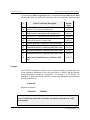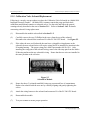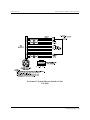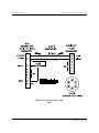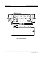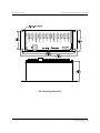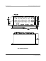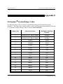
1
Intelligent Pressure Scanner User’s Manual (Models 9016, 9021, 9022) August 2012 NetScanner™ System www.meas-spec.com © This User’s Manual is a copyright product of Measurement Specialties Inc., 2012 Permission is hereby granted to make copies and distribute verbatim copies of this manual, provided the copyright notice and this permission notice are preserved on all copies. Measurement Specialties Inc. 1000 Lucas Way Hampton, VA 23666 USA Phone: (757) 766-1500 Toll Free: (800) 745-8008 Fax: (757) 766-4297 E-mail: [email protected] Measurement Specialties Inc. NetScanner System (9016, 9021, & 9022) User’s Manual ©This User’s Manual is a copyright product of Measurement Specialties Inc., 2012 Permission is hereby granted to make copies and distribute verbatim copies of this manual, provided the copyright notice and this permission notice are preserved on all copies. -i- www.meas-spec.com Measurement Specialties Inc. REVISION NetScanner System (9016, 9021, & 9022) User’s Manual REVISION HISTORY PRINT DATE 1 Original - 2nd Edition 4/94 2 3rd Edition (add Model 902x and 9016) 11/97 3 4th Edition 3/98 4 5th Edition 9/99 5 6th Edition 03/00 6 7th Edition (delete Optomux references and add multi-point calibration procedures) (add information about the 9021R- ruggedized version) 02/01 7 8th Edition (officially change name from 9021R to 9022, a new ruggedized version of the 9021) 03/02 8 9th Edition (added new commands and updates to Chapter 3, Chapter 4, and Chapter 5 to accommodate the 9022) 07/02 9 10th Edition (new Chapter 7 - deletes all references to NETSTART as the startup software, and replaces it with a brief description of NUSS 01/02 11th Edition adds information regarding using the 9022 with third-party transducers that do not have temperature compensation. Changes wiring diagram. 06/03 11 12th Edition deletes references to the Repair Department for RMAs. 04/04 12 Includes Application Note concerning mixing transducers with and without temperature sensor attached to Model 9022 and adds references for high frequency in Model 9022. 01/05 13 Added new commands for Model 9022 & Model 9016 09/07 14 Updated contact information to MEAS 08/12 10 - ii - www.meas-spec.com Measurement Specialties Inc. NetScanner System (9016, 9021, & 9022) User’s Manual Preface This manual describes the NetScanner System Intelligent Pressure Scanner modules (Models 9016, 9021, and 9022). It does not cover the 98RK Scanner Interface Rack, model 9816 Intelligent Pressure Scanner, nor models 903x (Pressure Standards/Controllers) and the 9116 Intelligent Pressure Scanner. These products are covered in their individual User’s Manuals. This manual is divided into seven (7) chapters and several appendices, each covering a specific topic. They are summarized below: Chapter 1: General Information describes Models 9016, 9021, and 9022 Intelligent Pressure Scanners and their various options. Chapter 2: Installation and Set Up describes the unpacking and inspection of a module, and its connection to power, pressure, and a communications network. Chapter 3: Programming & Operation provides the information needed to program a module from a host computer and to get meaningful data from it. Chapter 4: Calibration describes methods of calibrating a module. Chapter 5: Service describes general safety precautions and maintenance procedures. Chapter 6: Troubleshooting describes module techniques. Chapter 7: Start-up Software briefly describes NUSS software. Appendix A: Appendix B: Appendix C: Appendix D: Appendix E: Appendix F: All Commands — Quick Reference Response Error Codes Cable Diagrams Module Mounting Dimensions NetScanner System Range Codes NetScanner System/9000 Series Products - iii - troubleshooting www.meas-spec.com Measurement Specialties Inc. NetScanner System (9016, 9021, & 9022) User’s Manual Appendix G: Binary Bit Map Our Company Measurement Specialties Inc. (MEAS) develops, manufactures, and services level and pressure measuring instruments where the highest level of traceable accuracy is required for aerospace, industrial, municipal, and environmental applications. Our products have become the world standard for electronic level and pressure measurement and scanning. We are committed to the highest quality design, manufacture, and support of level and pressure instrumentation that is in the best interest of our customers. MEAS is an ISO9001:2000 certified company. Our Warranty MEAS warrants NetScanner System products to be free of defects in material and workmanship under normal use and service for one (1) year. Technical Support Monday through Friday, during normal working hours, (7:30 am through 5:30 pm, Eastern time) knowledgeable personnel are available for assistance and troubleshooting. Contact the Applications Support Group or the Customer Services Department at Measurement Specialties (757-766-1500 or toll free 1-800-745-8008) if your scanner is not operating properly or if you have questions concerning any of our products. E-mail assistance is available by contacting [email protected]. Merchandise Return Procedures If your scanner needs to be returned to Measurement Specialties, please obtain a Returned Merchandise Authorization (RMA) from the Customer Service Department. Be prepared to supply the following information when requesting the RMA: • • • • • • Part number Serial number Complete description of problems/symptoms Bill To and Ship To address Purchase order number (not required by MEAS warranty repairs) Customer contact and telephone number The above information, including the RMA number must be on the customer’s shipping documents that accompany the equipment to be repaired. MEAS also requests that the outside of the shipping container be labeled with the RMA number to assist in tracking the repairs. All equipment should be sent to the following address: - iv - www.meas-spec.com Measurement Specialties Inc. NetScanner System (9016, 9021, & 9022) User’s Manual ATTN: MEAS REPAIR DEPARTMENT (7-digit RMA number) Measurement Specialties Inc. 1000 Lucas Way Hampton, Virginia 23666 MEAS will return warranty items prepaid via UPS GROUND. If the customer desires another method of return shipment, MEAS will prepay and add the shipping charges to the repair bill. Incoming freight charges are the customer’s responsibility. The customer is also responsible for paying shipping charges to and from MEAS for any equipment not under warranty. All products covered under the MEAS warranty policy will be repaired at no charge. An analysis fee will be charged to quote the cost of repairing any item not under warranty. If, for any reason, the customer decides not to have the item repaired, the analysis fee will still be charged. If the quote is approved by the customer, the analysis fee will be waived. The quote for repair will be based on the MEAS flat rate for repair, calibration, and board replacement. When these prices do not apply, the quote will be based on an hourly labor rate plus parts. All replaced parts are warranted for 90 days from the date of shipment. The 90-day warranty is strictly limited to parts replaced during the repair. Website and E-Mail Visit our website at www.meas-spec.com to look at our new product releases, application notes, product certifications, and specifications. E-mail your questions and comments to us: [email protected]. Our Firmware This manual was prepared for various versions of module firmware as were released at the time of this manual publication. Addenda will be distributed as deemed necessary by MEAS. Any questions regarding firmware upgrades may be addressed to the Applications Support Group. Firmware revisions, manual addenda, and utility software may also be obtained from the MEAS web page at www.meas-spec.com. -v- www.meas-spec.com Measurement Specialties Inc. NetScanner System (9016, 9021, & 9022) User’s Manual Our Publication Disclaimer This document is thoroughly edited and is believed to be thoroughly reliable. Measurement Specialties Inc. assumes no liability for inaccuracies. All computer programs supplied with your products are written and tested on available systems at the factory. MEAS assumes no responsibility for other computers, languages, or operating systems. We reserve the right to change the specifications without notice. - vi - www.meas-spec.com Measurement Specialties Inc. NetScanner System (9016, 9021, & 9022) User’s Manual Table of Contents Chapter 1 — General Information ............................................................................ 1-1 1.1 Introduction ...................................................................................................... 1-1 1.2 Description of Instruments ................................................................................ 1-3 1.3 Options ............................................................................................................. 1-4 1.3.1 Pressure Ranges .................................................................................... 1-4 1.3.2 Manifolds and Pressure Connections ..................................................... 1-4 1.3.3 Communications Interfaces ................................................................... 1-5 Chapter 2 — Installation and Set Up ........................................................................ 2-1 2.1 Unpacking and Inspection ................................................................................. 2-1 2.2 Safety Considerations ....................................................................................... 2-1 2.3 Preparation for Use ........................................................................................... 2-1 2.3.1 Environment.......................................................................................... 2-1 2.3.2 Power .................................................................................................... 2-2 2.3.3 Mounting and Module Dimensions ........................................................ 2-2 2.3.4 Network Communications Hookup........................................................ 2-3 2.3.4.1 Ethernet Host Port Hookup ........................................................ 2-3 2.3.5 Diagnostic Port Hookup ........................................................................ 2-6 2.3.6 Pressure Connections ............................................................................ 2-6 2.3.6.1 RUN Mode Inputs ..................................................................... 2-7 2.3.6.2 CAL Mode Inputs ...................................................................... 2-8 2.3.6.3 Purge Mode Inputs..................................................................... 2-8 2.3.6.4 Leak Mode Inputs ...................................................................... 2-8 2.3.6.5 Supply Air ................................................................................. 2-9 2.3.7 9021 and 9022 Transducer Installation .................................................. 2-9 2.3.7.1 Installation of 9400, 9401, and 9402 Transducers .................... 2-10 2.3.7.2 Installation of All Other Transducers ....................................... 2-11 2.3.8 Case Grounding................................................................................... 2-11 2.3.9 Trigger Input Signal ............................................................................ 2-12 2.3.10 Power Up Checks and Self-Diagnosis.................................................. 2-12 Chapter 3 — Programming and Operation .............................................................. 3-1 3.1 Commands and Responses ................................................................................ 3-1 3.1.1 Introduction........................................................................................... 3-1 3.1.1.1 TCP/UDP/IP Protocols .............................................................. 3-1 - vii - www.meas-spec.com Measurement Specialties Inc. NetScanner System (9016, 9021, & 9022) User’s Manual Table of Contents (Cont.) 3.2 3.1.2 Commands ............................................................................................ 3-2 3.1.2.1 General Command Format ......................................................... 3-2 3.1.2.2 Command Field ......................................................................... 3-3 3.1.2.3 Position Field ............................................................................. 3-3 3.1.2.4 Datum Fields ............................................................................. 3-4 3.1.2.5 Format Field .............................................................................. 3-4 3.1.3 Responses ............................................................................................. 3-4 3.1.3.1 Interpreting Offset Values (Re-zero Calibration Adjustment) ..... 3-5 3.1.3.2 Interpreting Gain Values (Span Calibration Adjustment) ........... 3-6 3.1.3.3 Interpreting Engineering Unit Output ......................................... 3-6 3.1.4 Functional Command Overview ............................................................ 3-6 3.1.4.1 Startup Initialization ....................................................... 3-6 3.1.4.2 Module Data Acquisition ........................................................... 3-7 3.1.4.3 Calibration Adjustment of Offset/Gain Correction Coefficients .................................................. 3-8 3.1.4.4 Delivery of Data to Host ............................................................ 3-9 3.1.4.5 Network Query and Control Functions ....................................... 3-9 3.1.4.6 Other Functions ....................................................................... 3-10 Detailed Command Description Reference ...................................................... 3-10 A Power Up Clear ................................................................................... 3-12 B Reset ................................................................................................... 3-13 C Configure/Control Multi-Point Calibration .......................................... 3-14 V Read Transducer Voltages ................................................................... 3-22 Z Calculate and Set Gains ....................................................................... 3-24 a Read Transducer A/D Counts .............................................................. 3-26 b Read High-Speed Data ........................................................................ 3-28 c Define/Control Autonomous Host Streams .......................................... 3-29 h Calculate and Set Offsets ..................................................................... 3-45 m Read Temperature Counts ................................................................... 3-47 n Read Temperature Voltages ................................................................ 3-49 q Read Module Status ............................................................................ 3-51 r Read High-Precision Data ................................................................... 3-54 t Read Transducer Temperature ............................................................. 3-56 u Read Internal Coefficients ................................................................... 3-58 v Download Internal Coefficients ........................................................... 3-62 w Set Operating Options ......................................................................... 3-65 psi9000 Network Query ........................................................................ 3-69 psireboot Re-boot Module ....................................................................... 3-71 psiarp Change Module’s IP Address Resolution and Re-boot ............. 3-72 - viii - www.meas-spec.com Measurement Specialties Inc. NetScanner System (9016, 9021, & 9022) User’s Manual Table of Contents (Cont.) 3.3 Obsolete Commands ....................................................................................... 3-73 Chapter 4 — Calibration ........................................................................................... 4-1 4.1 Introduction ...................................................................................................... 4-1 4.2 Re-zero Calibration ........................................................................................... 4-3 4.2.1 Re-zero Calibration Valve Control ........................................................ 4-3 4.2.2 Re-zero Calibration Summary ............................................................... 4-4 4.3 Span Calibration ............................................................................................... 4-4 4.3.1 Span Calibration Valve Control ............................................................. 4-5 4.3.2 Span Calibration Summary .................................................................... 4-6 4.4 Integrated Multi-Point Calibration Adjustment ................................................. 4-7 4.4.1 Calibration Valve Control ..................................................................... 4-8 4.4.2 Multi-Point Calibration Summary ......................................................... 4-8 4.5 9021/9022 Analog Calibration ........................................................................ 4-10 4.5.1 Setup ................................................................................................... 4-11 4.5.2 Calibration Procedures ........................................................................ 4-11 4.6 Coefficient Storage ......................................................................................... 4-13 4.7 Non-Volatile Parameter Storage for “non-Digitally Compensated” Pressure Sensors (9021/9022 Only)............................................................................... 4-14 4.8 Line Pressure Precautions ............................................................................... 4-18 Chapter 5 — Service .................................................................................................. 5-1 5.1 Maintenance ..................................................................................................... 5-1 5.1.1 Common Maintenance .......................................................................... 5-3 5.1.2 Module Disassembly ............................................................................. 5-3 5.1.3 Electronic Circuit Board Replacement ................................................... 5-4 5.1.3.1 PC-206 Amplifier/Multiplexer Board......................................... 5-4 5.1.3.2 PC-242 Amplifier/Multiplexer Board......................................... 5-5 5.1.3.3 PC-280 Ethernet Microprocessor /A/D Board ............................ 5-6 5.1.3.4 PC-315, PC-316, and PC-317 Boards......................................... 5-7 5.1.4 Replacement of Transducers .................................................................. 5-8 5.1.5 Calibration Valve Solenoid Replacement............................................. 5-10 - ix - www.meas-spec.com Measurement Specialties Inc. NetScanner System (9016, 9021, & 9022) User’s Manual Table of Contents (Cont.) 5.2 5.3 5.4 5.1.6 Replacement of O-Rings ..................................................................... 5-10 5.1.6.1 DH200 Pressure Transducer O-Ring Replacement ................... 5-11 5.1.6.2 Tubing Plate O-Ring Replacement ........................................... 5-12 5.1.6.3 Adapter Plate O-Ring Replacement.......................................... 5-13 5.1.6.4 Calibration Manifold Piston O-Ring Replacement ................... 5-14 5.1.6.5 Solenoid Valve O-Ring Replacement ....................................... 5-15 9022 Excitation Trim ...................................................................................... 5-16 9022 Procedure for Changing the Excitation Jumper Setting (JB1) ................. 5-17 Upgrading Module Firmware .......................................................................... 5-17 5.2.1 Upgrading Firmware Via Host TCP/IP Port......................................... 5-18 Chapter 6 — Troubleshooting Guide ........................................................................ 6-1 6.1 Ethernet Module Troubleshooting ..................................................................... 6-1 6.1.1 Checking Module Power-up Sequence .................................................. 6-1 6.1.2 Checking Module TCP/IP Communications .......................................... 6-2 6.1.2.1 Module IP Address Assignment ................................................. 6-2 6.1.2.2 Host IP Address Assignment for Windows 95/98/NT ................ 6-4 6.1.2.3 Verifying Host TCP/IP Communications ................................... 6-4 6.2 Zero and Gain Calibration Troubleshooting ...................................................... 6-6 6.3 User Software ................................................................................................... 6-7 Chapter 7 — Start-up Software ................................................................................. 7-1 7.1 Introduction ...................................................................................................... 7-1 Appendices Appendix A: Appendix B: Appendix C: Appendix D: Appendix E: Appendix F: Appendix G: All Commands — Quick Reference NetScanner System Response Error Codes Cable Diagrams Mounting Diagrams NetScanner System Range Codes NetScanner System/9000 Series Products Binary Bit Map -x- www.meas-spec.com Measurement Specialties Inc. NetScanner System (9016, 9021, & 9022) User’s Manual List of Figures Figure 1.1 Figure 2.1 Figure 2.3 Figure 2.3 Figure 2.4 Figure 2.4a Figure 2.5 Figure 4.1 Figure 4.2 Figure 4.3 Figure 4.4 Figure 4.5 Figure 5.1 Figure 5.1a Figure 5.2b Figure 5.2c Figure 5.2 Figure 5.2a Figure 5.3 Figure 5.3a Figure 5.3b Figure 5.4 Figure 5.5 Figure 5.6 Figure 5.7 Figure 5.8 Figure 5.9 NetScanner System Pneumatic Intelligent Pressure Scanners ................. 1-2 9016, 9021, 9022 Power Pin Assignments ............................................. 2-2 Ethernet Host Port Connector Pins ........................................................ 2-3 Ethernet Network Topology .................................................................. 2-5 9021 Transducer Wiring ...................................................................... 2-10 9022 Transducer Wiring ...................................................................... 2-10 9022 Jumper Set for 10 VDC Excitation .............................................. 2-11 Calibration Manifold RUN Position ...................................................... 4-2 Calibration Manifold CAL Position ....................................................... 4-2 Calibration Manifold PURGE Position .................................................. 4-2 Calibration Manifold LEAK CHARGE Position ................................... 4-2 9021 and 9022 Voltage Input Connections .......................................... 4-11 Exploded View of 9016 and 9022.......................................................... 5-1 9016 Top Plate ...................................................................................... 5-2 9021 Top Plate ...................................................................................... 5-2 9022 Top Plate ...................................................................................... 5-2 9016 Scanner Out of Housing ................................................................ 5-4 9022 Scanner Out of Housing ................................................................ 5-4 PC-203 Board........................................................................................ 5-6 9022 PCBs Outside the Housing ............................................................ 5-7 9022 PCBs Apart .................................................................................. 5-7 Top View of DH200 .............................................................................. 5-9 Solenoid in Module ............................................................................. 5-10 DH200 Transducer O-Ring Replacement............................................. 5-11 Solenoid Valve O-Ring Replacement .................................................. 5-15 PC-317 Board (Trim Potentiometer and Jumper) ................................. 5-16 Update Firmware Screen ..................................................................... 5-18 List of Tables Table 2.1 Table 3.1 Table 3.2 Table 5.1 Diagnostic Port Wiring .......................................................................... 2-6 Error Codes ........................................................................................... 3-5 Intelligent Pressure Scanner Commands .............................................. 3-10 Component Cross Reference ................................................................. 5-2 - xi - www.meas-spec.com Measurement Specialties Inc. NetScanner System (9016, 9021, & 9022) User’s Manual Chapter 1 General Information 1.1 Introduction This User’s Manual will: • • • Explain the electrical and pneumatic pressure connections for the NetScanner System Models 9016, 9021, and 9022 Intelligent Pressure Scanners. Instruct you on how to program each module with computer software. Instruct you on using the start-up software to manipulate and acquire data from each module. Model 9016 is a pneumatic Intelligent Pressure Scanner, with integral pressure transducers and a pneumatic calibration manifold. Models 9021 and 9022 are all-media Intelligent Pressure Scanners which may be fitted with up to twelve (12) external all-media transducers (9400, 9401, 9402, or third party). Because of the external nature of these transducers, and the variety of pneumatic or hydraulic media supported, the 9021/9022 do not contain an integral calibration manifold. Both models provide engineering unit pressure data with guaranteed system accuracy. This is achieved by reading factory-determined pressure and temperature engineering-unit data conversion coefficients from their transducers’ non-volatile memories at power-up. They also allow additional adjustment coefficients to be “fine-tuned” with a multi-point calibration under host control (e.g., possibly utilizing optional 903x Pressure Calibrator modules). Models 9016, 9021 and 9022 provide 10-Base-T Ethernet communications for their Host Port (with TCP/UDP/IP protocol). 1-1 www.meas-spec.com Measurement Specialties Inc. NetScanner System (9016, 9021, & 9022) User’s Manual NOTE: The newest Intelligent Pressure Scanner is the 9022. Its serial numbers begin with 1000. The 9022 is similar in function to the 9021 (using external sensors), however, the 9022 features circular (military style connectors), splash-proof case and connectors, antialiasing filters, and a jumper selectable precision 5 or 10 volt excitation voltage for use with third-party sensors. The overall dimensions of the 9022 are slightly larger than the 9021 due to a thicker top plate. Model 9016 Model 9021 Model 9022 Figure 1.1 NetScanner™ System Model 9016, 9021 and 9022 Intelligent Pressure Scanners 1-2 www.meas-spec.com Measurement Specialties Inc. 1.2 NetScanner System (9016, 9021, & 9022) User’s Manual Description of Instruments The NetScanner System family of Intelligent Pressure Scanner modules are flexible pressure measuring devices intended for use in test and production environments. Models are available with 12 (Model 9021/9022), or 16 (Model 9016) channels, each with individual pneumatic or allmedia transducers per channel. The most distinctive features are highlighted below: • Pre-calibrated Transducer – a memory chip containing full calibration data is embedded within each internal transducer (9016) or external Series 9400 transducer (9021/9022). • Individual transducer per measurement input channel – mixed transducer ranges may be installed in a single 9016 module or attached to a 9021/9022 module. • Low cost per point – per—channel cost is less than a typical industrial pressure transducer/transmitter. • High accuracy – Model 9016 pressure scanners are capable of accuracies up to ±0.05%. Accuracy is maintained through use of built-in re-zero, span, or multi-point calibration capabilities. Model 9021/9022 pressure scanners provide accuracies better than ±0.10% FS. Accuracy is maintained for six (6) months after calibration. • Low thermal errors – each internal transducer and each external 904x transducer contains an individual temperature sensor and thermal calibration data for internal use by software correction algorithms. Thermal errors are reduced as low as ±0.001%FS/°C over the calibrated temperature span. • Re-zero upon demand (Models 9016) — an integrated calibration valve allows for automatic re-zero adjustment calibration of dry gas transducers to null offset drift errors. • Ease of transducer replacement — factory calibrated transducer assemblies may be stocked and rapidly replaced in the field. Storage of thermal coefficients within the transducer allows for ‘plug and play’ transducer replacement. • Ease of calibration — each 9016 module contains a pneumatic calibration manifold and software commands to automatically perform re-zero, span, and multi-point adjustment calibrations. New offset and gain coefficients that result from the most recent calibration may be stored in non-volatile transducer memory. • Measurement flexibility — each 9021/9022 module is capable of measuring general purpose voltage signals on any channel not populated with a 9400-type transducer. Full-scale ranges of ±50, ±100, ±250 and ±4500 mV are supported through programmable gain amplifier circuitry. 1-3 www.meas-spec.com Measurement Specialties Inc. NetScanner System (9016, 9021, & 9022) User’s Manual • Ease of use — modules have simple command sets and provide engineering units output. They may interface directly to a desktop or laptop computer or they may be interconnected into a large network controlled by many types of host computers. • Connectivity — use of industry-standard communications network protocols to control and read data from NetScanner™ System modules allows distribution to the point of measurement and ensures compatibility with third party hardware and software. 1.3 Options 1.3.1 Pressure Ranges Model 9016 contains sixteen (16) DH200 transducers. These transducers are available with full scale pressure ranges from 10" H2O (inches of water column) to 750 psid (2.5 kPa to 5200 kPa). Transducers with different pressure ranges may be combined in a single module. Models 9021 and 9022 can attach up to twelve (12) Series 9400 or third party external all-media transducers. The 9400 gauge-type transducers are available with full-scale pressure ranges from 5 psi to 10,000 psi (35 kPa to 69000 kPa). The 9401 absolute-type transducers are available with full-scale pressure ranges from 15 psia to 10,000 psia (105 kPa to 69000 kPa). The 9402 wet-wet differential type transducers are available with full scale ranges from 5 psi to 250 psi (35 kPa to 1725 kPa). Transducers with different pressure ranges may be attached to a single module. Please consult the Sales Department at Measurement Specialties for availability of other pressure ranges (1-800-678-SCAN (7226). 1.3.2 Manifolds and Pressure Connections Model 9016 sixteen-channel Intelligent Pressure Scanners are available with a true differential or common reference pneumatic manifold, and have a standard purge and leak check manifold. They are available with standard 1/8" or optional 1/16" and 1/4" compression fittings. All fittings utilize an SAE 5/16 - 24 O-ring boss which supports a variety of other adapter compression fittings. They are also available with a quick disconnect plate which contains 0.063" bulge tubulation. The common differential version is available with all choices of fittings. The true differential version is available with 0.063" bulged tubulation fittings only. Models 9021 and 9022 12-channel Intelligent Pressure Scanners have no internal manifold or pressure transducers. Instead, they have up to twelve (12) externally connected type 9400, 9401, or 9402 all-media pressure transducers. 9400, 9401, and 9402 transducers may be purchased with 1-4 www.meas-spec.com Measurement Specialties Inc. NetScanner System (9016, 9021, & 9022) User’s Manual a variety of standard pressure fittings. Any necessary valves and manifolds must be customersupplied if automatic calibration with the appropriate medium is desired at the module installation site. Both the 9021 and 9022 scanners are designed to operate with either PSI or third-party transducers. Consult the Sales Department at Measurement Specialties at 1-800-678-SCAN (7226) for availability of other input fittings. 1.3.3 Communication Interfaces All standard NetScanner™ System Intelligent Pressure Scanners provide temperature compensated and linearized pressure data in engineering units via digital methods. They have a 10Base-T Ethernet host communications interface using industry standard TCP/IP or UDP/IP protocol. This interface provides high data transfer rates and system connectivity. 1-5 www.meas-spec.com Measurement Specialties Inc. NetScanner System (9016, 9021, & 9022) User’s Manual This page intentionally left blank 1-6 www.meas-spec.com Measurement Specialties Inc. NetScanner System (9016, 9021, & 9022) User’s Manual Chapter 2 Installation and Set Up 2.1 Unpacking and Inspection The NetScanner System product family has many components which may be purchased either as an entire system, or as individual pieces of equipment. Before assembling the system, use the shipping bill as a reference to ensure that all parts have arrived. Measurement Specialties takes no responsibility for equipment that is damaged during shipment. If containers are broken, ripped, or damaged, contact the transportation carrier. If the equipment itself appears to be damaged, contact Customer Service at Measurement Specialties. Each NetScanner System Intelligent Pressure Scanner shipment will contain the following minimum components: • • • 2.2 Model 9016 or 9021/9022 Intelligent Pressure Scanner module Start-up software diskette(s) or CD-ROM NetScanner System User’s Manual for Intelligent Pressure Scanners (Models 9016/9021/9022) (Hard copy and/or CD-ROM) Safety Considerations Always wear safety glasses when operating this equipment or when working with pressurized lines. Always ensure that high pressure lines are properly secured and that all pneumatic lines are rated for the proper pressure and temperature environments. All system power should be OFF during installation (or removal) of any components in a NetScanner System module. Failure to turn power OFF prior to installation may cause permanent damage to the module. Use caution and check line voltages before applying power to the module. 2.3 Preparation for Use 2.3.1 Environment All standard Intelligent Pressure Scanners are factory calibrated to be accurate over a specified temperature range, but may be operated or stored over a wider temperature range (see NetScanner System Data Sheet, published separately). Operating or storing an instrument outside its specified range(s) will result in a loss of measurement accuracy and may cause permanent damage to the instrument electronics. 2-1 www.meas-spec.com Measurement Specialties Inc. NetScanner System (9016, 9021, & 9022) User’s Manual WARNING: Exceeding the specified storage or operating temperatures may result in permanent damage to the NetScanner System electronics. 2.3.2 Power Models 9016, 9021, and 9022 Intelligent Pressure Scanners need only a single unregulated power supply. Models 9016 and 9021/9022 have a single round, ruggedized connector through which all power and input/output signals pass as shown in Figure 2.1. Improper connection of power to the Intelligent Pressure Scanner can result in permanent damage to module electronics. WARNING: Figure 2.1 9016, 9021, 9022 Power Pin Assignments 2.3.3 Mounting and Module Dimensions Detailed mechanical drawings for each module are included in Appendix D. 2-2 www.meas-spec.com Measurement Specialties Inc. 2.3.4 NetScanner System (9016, 9021, & 9022) User’s Manual Network Communications Hookup Every NetScanner System Intelligent Pressure Scanner contains a Host Port, allowing it to be interconnected in a network with other modules and a host computer. Models 9016, 9021, and 9022 have an Ethernet Host Port using TCP/IP and UDP/IP transmission protocols. 2.3.4.1 Ethernet Host Port Hookup The Ethernet Host ports of every model 9016, 9021, and 9022 Intelligent Pressure Scanner module, and its host computer, may be interconnected in a “star” network via a standard 10Base-T interconnection hub or switch. These standard devices will have their own power requirements. Such a hub treats the host computer connection and all NetScanner System module connections alike. Ethernet communications pin assignments for the 9016, 9021, and 9022 electrical connector are shown in Figure 2.2. See Figure 2.3 for typical network topology. Figure 2.2 Ethernet Host Port Connector Pins The host and each module must have a unique Ethernet Hardware Address (a.k.a. MAC Address) and a unique IP Address. The Ethernet Hardware address is generally fixed (at manufacturing time of the Ethernet microprocessor board inside the module). The Ethernet Hardware address is shown on each module’s label. The Ethernet Intelligent Pressure Scanners are capable of supporting various methods for IP address assignment, using either the factory default (static IP addressing) or user-configured Static IP addressing or Dynamic IP address assignment. Dynamic IP address assignment is through the use of RARP or BOOTP protocols. Unless your application requires the use of Dynamic IP address assignments, it is strongly suggested that the module be left configured for the Static IP address protocol. This default method is typically the simplest method for using the Intelligent Pressure Scanner. In the Static IP addressing mode, the module will use a factory default IP address on power-up. This default address is set to 200.20x.yyy.zzz where x is derived from the module type (0 for 2-3 www.meas-spec.com Measurement Specialties Inc. NetScanner System (9016, 9021, & 9022) User’s Manual 9016 and 1 for 9021/9022) and yyy.zzz is derived from the module serial number. A similar method is used to calculate each module’s Ethernet hardware address shown on the module tag. Note that each of these fields (separated by a period, ‘.’) is a decimal representation of a byte value. This means that each field may have a maximum value of 255. For 9016 modules with serial less than 255, this default IP address will be 200.200.0.zzz where zzz is the serial number (i.e., 9016 serial number 212 is IP 200.200.200.212) . For 9016 modules with serial numbers greater than 255, the default IP of 200.200.y.zzz is calculated as follows: y is the integer result of dividing the module serial number by 256. zzz is the remainder of dividing the serial number by 256 (serial number modulus 256). These calculations may be verified by checking that y * 256 + zzz equals the original module serial number. Once a module has powered-up and has assigned itself a default IP address it is capable of communications. An alternate method for assigning an IP address to an Ethernet module is referred to as a Dynamic IP assignment. This method allows a module to have its IP address dynamically assigned at power-up by an application running on a node of the TCP/IP or UDP/IP network. When configured for Dynamic IP address assignment protocols, the reset module will broadcast its Ethernet hardware (MAC) address on the network in a Dynamic IP request packet. This broadcast packet identifies the module by its hardware address and requests that a dynamic IP server application return to it an IP address for use. Once this broadcast message is received, the dynamic server application will then return an IP address to the module in a dynamic IP reply packet. Most dynamic IP server applications determine this IP address from a user maintained file that lists Ethernet hardware addresses with their desired IP address. If modules are added to the network or module IP addresses are to be changed, the user can simply edit this configuration file. This capability is common on most UNIX based machines and is also available (although less common) in some TCP/IP packages available for PC platforms. Support of the Dynamic IP server protocol is not currently included in the Windows® 95/98 or Windows® NT operating systems. In order to allow users of PC platforms to make use of the Dynamic IP capabilities of the 9016, 9021, and 9022, a simple Windows® 95/98/NT application is capable of acting as a Dynamic IP server. This application is referred to as BOOTP Lite since it actually makes use of the BOOTP protocol that closely resembles the Dynamic IP request. Like traditional dynamic IP servers, this application allows the user to configure a file that contains Ethernet hardware addresses and the corresponding IP address to assign to those devices. This application is free of charge and capable of running as a background program on Windows® 95/98/2000 and NT machines. It may be downloaded from the MEAS website, www.meas-spec.com. NOTE: After closing the TCP/IP connection to the module, the host must wait 10 seconds before re-connecting. 2-4 www.meas-spec.com Measurement Specialties Inc. NetScanner System (9016, 9021, & 9022) User’s Manual Figure 2.3 Ethernet Network Topology 2-5 www.meas-spec.com Measurement Specialties Inc. NetScanner System (9016, 9021, & 9022) User’s Manual Use of Static or Dynamic IP settings may be selected through the Set Operating Options ('w') command. If you are unsure how your module is configured, check the Tx LED during module power-up. If it begins to blink periodically after the module power-up, your instrument is configured for the Dynamic IP assignment protocol. (Tx LED remains OFF in static IP configuration.) If configured for Dynamic IP assignment, a dynamic server must be configured on the network to return an IP address to the module. Without an IP address, the host will be unable to open a TCP/IP or UDP/IP connection to the module. 2.3.5 Diagnostic Port Hookup Each NetScanner System module contains a Diagnostic Port that supports diagnostic and operational functions. The Diagnostic Port has only a simple RS-232 asynchronous serial interface. The connections are made via certain pins of its common circular connector. Cable connection should be made according to Table 2.1. NetScanner System Diagnostic Port Connector GND Tx Rx Table 2.1 Diagnostic Port Wiring 2-6 www.meas-spec.com Measurement Specialties Inc. NetScanner System (9016, 9021, & 9022) User’s Manual The RS-232 interface is capable of supporting simple asynchronous communications with fixed parameters of 9600 baud, no parity, 8 data bits, and 1 stop bit. Only communication cable lengths less than 30 feet (10 m) are recommended. The 9016, 9021 and 9022 use the diagnostic interface for optional configuration and diagnostic purposes only. The diagnostic port functions on the 9016, 9021, and 9022 are generally not required by the end user. Standard cables for these modules do not include diagnostic port connections. 2.3.6 Pressure Connections All pneumatic connections to Model 9016 are found on the instrument top panel. The function of each input port is clearly engraved or printed next to each input. Connections are through bulge tubing, compression fittings or special user-supplied fittings on the tubing plate. All pneumatic inputs to these modules should contain dry, non-corrosive gas only. For Model 9021/9022, all pneumatic or hydraulic connections are to the individual 9400, 9401, or 9402 (or third party) all-media transducers mounted externally from the module itself. All 9016 standard Intelligent Pressure Scanners are supplied with the purge/leak check calibration manifold. Through software commands, this valve may be placed in one of four positions; RUN, CAL, PURGE, or LEAK-CHARGE. Pneumatic input requirements for these four operating positions are described in the following sections. The following guidelines should be used when installing pressure connections to all NetScanner System Intelligent Pressure Scanner modules. • Always wear safety glasses when working with pressurized lines. • Ensure that user input pressure will not exceed the proof pressure ratings of the corresponding instrument transducer. Applying excessive pressure to measurement inputs can permanently damage the pressure transducers. • Ensure that all tubing material is rated for the expected pressure and environmental conditions. Failure to use the proper tubing material may result in ruptured lines and possible personal injury. • Ensure all high pressure lines are properly secured. • Place retaining springs over all bulge tube fittings to ensure pneumatic lines remain attached and leak free. Springs should be pushed down on connections so that half of the spring length extends past the tube bulge. Warning: Introduction of contaminants or corrosive materials to the module pneumatic inputs may damage module transducers, manifolds, and O-ring seals. 2-7 www.meas-spec.com Measurement Specialties Inc. NetScanner System (9016, 9021, & 9022) User’s Manual Users of the 9021 and 9022 may proceed to Section 2.3.7 since these modules do not require any pneumatic connections to the module itself. 2.3.6.1 RUN Mode Inputs The standard pneumatic tubing plates (for the 9016) contain sixteen numbered pneumatic input channels. These numbered inputs are attached to corresponding pressure transducers inside the instrument and should be pneumatically attached to the pressure measurement points under test. The standard tubing plate also contains an input labeled RUN REF. The RUN REF input is pneumatically connected to the reference side of all internal DH200 pressure transducers. The RUN REF connection is used for situations where all channels have one reference pressure. The reference pressure may be as high as 250 PSI (1720 kPa). This input may also be left unattached to provide atmospheric reference pressure. When using instruments with the reference per channel option (true differential), two pneumatic inputs will be provided for every numbered channel. These inputs are labeled ‘P’ and ‘R’. The ‘P’ connection is the test pressure input. The ‘R’ connection is the transducer reference input pressure. Since each channel has its own reference pressure input, the RUN REF input is not provided on the true differential tubing plate. 2-8 www.meas-spec.com Measurement Specialties Inc. 2.3.6.2 NetScanner System (9016, 9021, & 9022) User’s Manual CAL Mode Inputs The 9016 model tubing plates contain inputs labeled CAL and CAL REF. When the module’s internal calibration valve is placed in the CAL/RE-ZERO position, all DH200 transducer pressure inputs are pneumatically connected to the CAL input port. All DH200 reference inputs are pneumatically connected to the CAL REF input port. The CAL input may be used to perform on-line zero adjustment of the transducers. The CAL input may also be used for DH200 span adjustment calibrations and accuracy tests if appropriate pressure calibrators (such as the 903x series) are available. Span calibration of multi-range scanners may also utilize the CAL port if the highest applied pressure does not exceed the proof pressure rating of any other installed transducer, otherwise the individual transducers must be calibrated with the valve in the RUN position. When the internal calibration valve is in the CAL/RE-ZERO position, the RUN inputs (RUN REF and numbered input ports) are pneumatically dead-ended to prevent migration of contaminants into the instrument. 2.3.6.3 PURGE Mode Inputs All standard 9016 models contain a purge/leak check option. The purge option allows users to apply positive pressure to the PURGE input which will then be vented out of the user input ports, forcing contaminants (such as moisture) out of the pneumatic input lines. Note that on common reference 9016 scanners, only the numbered input ports will be purged (RUN REF is not purged). True differential 9016 scanners will purge both the run and reference input ports for all channels. The purge supply provided to the 9016 must always be a higher pressure than the highest pressure present on the input ports of the module. The purge supply must also be capable of maintaining proper purge pressure at the high flow rates encountered while the module is in the purge mode. Warning: Failure to provide proper purge supply pressure will result in migration of moisture and contaminants into the 9016 module which can result in permanent damage to module components. When commanded into the PURGE position, the purge input pressure will be connected to the numbered measurement input ports allowing for a flow of air away from the instrument. The purge cycle should be terminated by commanding the 9016 into a non-purge mode such as CAL. Purge cycles should never be terminated by turning off the purge supply air while in the purge position. 2-9 www.meas-spec.com Measurement Specialties Inc. 2.3.6.4 NetScanner System (9016, 9021, & 9022) User’s Manual LEAK Mode Inputs The purge/leak charge valve design includes a leak check feature capable of testing the integrity of user pneumatic connections as well as those within the 9016 module. For the leak mode to be used, all RUN mode pressure inputs must be dead ended (closed) by the user. When the 9016 is commanded into the LEAK-CHARGE position, the CAL input port will be pneumatically connected to module run side inputs. Common reference modules will connect only the numbered run side inputs to CAL (RUN REF is not charged). True differential (reference per port) modules will connect both the measurement input and reference port to CAL. While in the LEAK-CHARGE position, a test pressure may be applied through the CAL port which will charge the dead ended run side tubulation. Test pressures applied to the CAL port during the leak check operation must not exceed the full scale pressure of any internal transducers. Once the lines are charged, the 9016 may be commanded back to the RUN position. This will reattach the charged run side lines to their corresponding internal transducer. Consecutive pressure readings from the 9016 will now allow user calculation of the line leak rates. Once returned to the RUN position, lack of a pressure indicates a gross leak. A slowly declining pressure indicates a slight leak. A leak is more difficult to detect as tubing volume increases. In the case of true differential units where both sides of the sensor are pressurized with the leak test pressure, an initial differential pressure of 0.0 psi should be measured when the unit is placed in the RUN position. If the measurement or RUN side of the channel leaks at a rate greater than the reference side, a resulting negative differential pressure will be measured. Likewise, if the reference port tubing leaks at a rate greater than the measurement side, a resulting positive differential pressure will be measured. 2.3.6.5 Supply Air The 9016 models require a 80 psig minimum dry air (or inert gas) supply which is used to shift the internal calibration valve between its different positions. Each module contains a fitting marked “SUPPLY” for this input. Internal solenoid valves direct this supply pressure to the proper control port on the calibration valve as required by instrument commands. The absence of sufficient supply air to the module will prevent the calibration valve from shifting into requested positions (i.e., RUN, CAL, PURGE, LEAK-CHARGE). WARNING! Supply air should not exceed 125 psi (875 kPa). Excessive pressure may damage the internal solenoids. 2 - 10 www.meas-spec.com Measurement Specialties Inc. 2.3.7 NetScanner System (9016, 9021, & 9022) User’s Manual 9021 and 9022 Transducer Installation Models 9021 and 9022 interface to twelve external transducers or signal sources. Although this module is intended primarily for use with Model 9400, 9401, and 9402 All-Media Transducers, it may also be used with many third party transducers with suitable analog outputs. When using the 9022 with third party pressure sensors that lack a temperature output signal, you must short the temperature signal input (pin D of the circular connector) to its reference line (pin C of the circular connector). This may be done directly on the connector. Transducers should be installed to the 9021/9022 as described on the following pages. Warning: Always ensure that the Model 9021/9022 power is OFF before connecting or disconnecting external transducers. The 12 volt transducer supply line is fuse-protected. The 9021 modules have a green LED at the bottom center of the case, indicating the presence of 12 volt power to the external transducers. The indicator LED is not present on the 9022. 2.3.7.1 Installation of 9400, 9401 and 9402 Transducers Warning: Improper electrical connections between the Model 9021/9022 and external transducers can result in permanent damage to the scanner and the external transducer. 9400, 9401, and 9402 transducer cables are typically ordered from MEAS pre-wired for use with the 9021/9022. If it is necessary to fabricate interface cables to interface the Series 9400 transducer to the 9021, the diagram in Figure 2.4 should be used. The 9021 makes use of 9-pin D-shell mating connectors. The 9022 uses circular (military) style connectors. See Figure 2.4a. Additional wiring diagrams can be found in Appendix C. 2 - 11 www.meas-spec.com Measurement Specialties Inc. NetScanner System (9016, 9021, & 9022) User’s Manual Figure 2.4 9021 Transducer Wiring 2.3.7.2 Figure 2.4a 9022 Transducer Wiring Installation of All Other Transducers If other analog output transducers are used with the 9021 they must provide an analog output less than the 9021 maximum input range of ±5 VDC. These transducers can be interfaced to the 9021 as shown in Figure 2.4. When using external transducers, both the 9021 and 9022 modules provide a +12VDC unregulated supply voltage to power the transducer. The 9022 has a jumper (JB1) on the PC-317 board for selecting the precision 5 or 10 VDC excitation source. See Figure 2.5. JB1 is a three-pin jumper. When the two pins closest to the edge of the board are connected (pins 2 and 3), the configuration is set for 10 VDC excitation. When the center and the innermost pins are connected (pins 1 and 2), the configuration is set for 5 VDC excitation. Please refer to Section 5.12 for module disassembly instructions if changes to the excitation voltage are needed. 2 - 12 www.meas-spec.com Measurement Specialties Inc. NetScanner System (9016, 9021, & 9022) User’s Manual Figure 2.5 9022 Jumper (JB1) Set For 10 VDC Excitation NOTE: The factory default setting for jumper JB1 is 10 VDC 2.3.8 Case Grounding The 9016 and 9021/9022 modules contain a case bypass capacitor which allows the module case to be mounted on hardware with a small common mode line voltage (less than 20 Volts). 2.3.9 Trigger Input Signal Models 9016, 9021, and 9022 each support the use of a data acquisition synchronization signal, sometimes called “Hardware Trigger.” When configured through the Define/Control Host Stream (‘c’) command, the trigger signal can be used to initiate and synchronize data acquisition and stream outputs to the host. The trigger signal is intended to be a 2-wire differential signal brought in through the 9016, 9021, or 9022 main electrical connector. The signal may be driven by a standard TTL compatible device. The switching threshold for this signal is set at 2.5 VDC. 2.3.10 Power Up Checks and Self-Diagnostics Upon power-up of the module, the internal firmware will perform a number of self-diagnostic checks. The results of these tests are reflected by the ‘OK’ LED on the top panel. The 9016, 9021, and 9022 modules complete the power up and self diagnostics in approximately 30 seconds. See Chapter 6, Troubleshooting Guide for additional information and potential problem areas during the power-up sequence. 2 - 13 www.meas-spec.com Measurement Specialties Inc. NetScanner System (9016, 9021, & 9022) User’s Manual Chapter 3 Programming and Operation 3.1 3.1.1 Commands & Responses Introduction This chapter describes all commands a host computer program may send to a NetScanner System Intelligent Pressure Scanner module, as well as the data or status responses returned by the module. Most applications require a working knowledge of only a small number of these commands. Most commands apply to all pressure scanner models. However, some apply only to specific models as will be noted in the command description (e.g., Model 9016 or Model 9022). Models 9016, 9021, and 9022 (stand alone scanner modules), have an Ethernet interface, and use layered TCP/IP or UDP/IP transmission protocols to communicate with a host computer. All commands/responses to/from NetScanner System modules are embedded in the data fields of either a TCP or UDP packet header. In turn, these packets are themselves embedded in the data field of an IP packet header, which is embedded in the data field of an Ethernet packet header. Thus, the term layered protocols. 3.1.1.1 TCP/UDP/IP Protocols Both TCP/IP and UDP/IP protocols are a well-established set of rules for communicating over a network (LAN, intranet, or internet), and are independent of the network’s physical medium. All the modules use the TCP/IP protocols for most commands and responses since the TCP layer provides a robust error detection and correction mechanism. TCP/IP requires a formal connection be established between host and module. The simpler UDP layer, requiring no formal connection, is utilized for a subset of commands and query responses. Using the underlying basic IP protocol, the host computer and interconnected modules are all “peers” that can communicate equally. Each “peer” must have its own unique “logical” IP Address (as well as its own unique “physical” Ethernet Address) to be directly addressed. Any “peer” may initiate transmissions without permission from the receiver. In the NetScanner System implementation, the host computer is normally a client and generally initiates most transmissions by sending commands to the modules, which are normally servers. However, a module can initiate its own transmissions in some operating modes (e.g., the hardware-triggered or free-run autonomous host streams generated by the Configure/Control Autonomous Host Streams (‘c’) command). 3-1 www.meas-spec.com Measurement Specialties Inc. NetScanner System (9016, 9021, & 9022) User’s Manual A “peer” may be directly addressed by its IP address (in xxx.xxx.xxx.xxx format), or by use of a predefined logical name that allows its IP Address to be looked-up in the sender’s database or in a central network server’s database. The Windows® 95/98/2000/NT operating systems provide a simple text file database called “Hosts.” Review the file “Hosts.sam” in the “C:\windows” directory. Modify and rename it “Hosts.” (no file extension) to activate it. Before the host computer and any module can communicate with the higher level TCP/IP protocols, the host (client) must request a connection be established with the module (server). Each module expects all such requests for connection to be requested by its IP Address, and directed to “well-known” port 9000 (default). After the connection is made, a socket is established as a logical handle to this connection. The host and module may then communicate, via this socket, until it is closed or is lost at either module or host end, due to power failure or reboot). The host and module may also communicate in a limited fashion without a connection, using the middle-level UDP/IP protocols. In that case, the host simply broadcasts commands via port 7000, and each module (that chooses to respond) returns the response on port 7001. Only a few commands use UDP/IP in NetScanner System modules. 3.1.2 Commands The commands (and responses) used by Models 9016, 9021, and 9022 modules consist of short strings of ASCII characters. The TCP/IP and UDP/IP protocols allow for the transfer of either printable ASCII characters or binary data. When using certain formats, internal binary data values are often converted to ASCII-hex digit strings externally. Such values may include the ASCII number characters ‘0’ through ‘9,’ the uppercase ASCII characters ‘A’ through ‘F,’ and the lowercase letters ‘a’ through ‘f’.’ These hex values may represent bit maps of individual options, or actual integer or floating point (IEEE) binary data values. In other cases (see optional format 7 below) binary data may be transmitted directly as 4-byte (32-bit) binary values without any formatting change. Such binary transmissions use big-endian (default) byte ordering but may be commanded to use little-endian for some data. 3.1.2.1 General Command Format A typical TCP/IP command (contained in the data field following a TCP packet header) is a variable-length character string with the following general fields: • a 1-character command letter (c). • an optional position field (pppp), a variable length string of hexadecimal digits. • a variable number of optional datum fields ( dddd): each a variable length string, normally formatted as a decimal number (with a leading space character, and with or without sign and/or decimal point, as needed). Using brackets ( [ ] ) to show optional elements, and ellipsis ( ...) to show indefinite repetition, a typical TCP/IP command may be viewed schematically as follows: 3-2 www.meas-spec.com Measurement Specialties Inc. NetScanner System (9016, 9021, & 9022) User’s Manual “c[[[[p]p]p]p][ dddd][ dddd]...]” From this schematic, it should be clear that the command letter (c) is required, the position field (pppp) immediately follows it, and may have 0, 1, 2, 3, or 4 characters, and there may be zero or more datum fields ( dddd), as required. For simplicity, the variable length nature of each “ dddd” string is not shown [with brackets] above, but the required leading space character is shown. The position field is similarly simplified (as “pppp”) below. A typical UDP/IP command (contained in the data field following a UDP packet header) is also a variable length character string, but has a simpler format. Generally, it has a variable length command string (cccccc), followed by one optional datum ( dddd) field (preceded by one space character): “cccccc[ dddd]” Since there are only a few simple UDP/IP commands, all references to commands below should assume TCP/IP commands, unless otherwise indicated. 3.1.2.2 Command Field All NetScanner System modules recognize a set of predefined commands. Most are TCP/IP commands, having only a single alphabetic letter for a command field. These are recognized only when a formal socket connection is established with the host computer. A few are UDP/IP commands with a longer command field. These are recognized any time the module has power applied. All commands are functionally summarized in the following sections and detailed in reference Section 3.2. 3.1.2.3 Position Field The Model 9016 Intelligent Pressure Scanner may contain up to sixteen (16) separate input/output channels, whereas the Models 9021 and 9022 have only twelve (12) channels. When commands affect certain channels scanned by the module, the position field is used to identify those channels as bits in a bit map. If a channel’s corresponding bit in the position field is set to a one (1), then that 3-3 www.meas-spec.com Measurement Specialties Inc. NetScanner System (9016, 9021, & 9022) User’s Manual channel is affected by the command. The least-significant (rightmost) bit 0 corresponds to Channel 1, and the most-significant (leftmost) bit 15 corresponds to Channel 16. Since neither model has more than sixteen (16) channels, the position field will usually be 16-bits, represented by four (4) ASCII-hex characters in the command. For example, only Channels 16 and 1 are selected below in this 16-bit (4-character) position field: Bit# 15 14 13 12 11 10 9 8 7 6 5 4 3 2 1 0 Chan# 16 15 14 13 12 11 10 9 8 7 6 5 4 3 2 1 Binary 1 0 0 0 0 0 0 0 0 0 0 0 0 0 0 1 Hex 8 0 0 1 The above position field, with all applicable bits set (i.e., FFFF for 16-channel module), specifies all channels. However, a module-independent variation allows a missing position field to designate all channels — but only when there are no other parameters following the position field in the command. For such commands, the hex position field may be reduced to 3, 2, or 1 characters when no channel bits need be set (1) in the discarded high-order characters (nibbles). The channel data requested will always be returned in order of highest requested channel to lowest requested channel. 3.1.2.4 Datum Fields Any datum fields in a command generally contain data to be sent to the module, usually specified by a position field bit map. In some commands (when data are received from a module instead) no datum fields are required in the command itself but the position field bit map is still used to specify the order that data are returned in the command’s response. In either case, the order bits are set (to 1) in the position field bit map (highest channel # to lowest channel#, left to right) is the order these datum fields are received or sent. Each datum field may be variable in length, whether part of the command itself or the command’s response. In its most common format, a datum begins with a space character (‘ ’), and is followed by an optional sign, decimal digits, and a decimal point, as needed (e.g., ‘ -vv.vvvvvv’). For other formats it may be a hex digit string or pure binary number. 3-4 www.meas-spec.com Measurement Specialties Inc. NetScanner System (9016, 9021, & 9022) User’s Manual 3.1.2.5 Format Field Some commands, that either send data to a module (as command parameters), or cause the host to receive data (via command’s response), have an extra format parameter (f digit) appended to (or specified in) the position field. This parameter, when specified (or implied by default), governs how internal data are converted to/from external (user-visible) form. • The most common format (f=0) causes each datum (in command or response) to be represented as printable ASCII numbers externally (with optional sign and decimal point as needed). Internally, the module sets/obtains each converted datum to/from a single precision binary (32-bit) IEEE float. • Some formats (f=1, 2, 5) encode/decode the internal binary format to/from ASCII hexadecimal external form. Some of these “hex dump” formats provide an external hex bit map of the internal binary value (float or integer as appropriate). Format 5 may encode/decode the internal float value to/from an intermediate scaled binary integer (e.g., float value * 1000 into integer, then to/from a hex bit map). • Two special “binary dump” formats (f=7 and f=8) may be used by some commands to accept/return binary data directly from/to the user’s command/response. Such values are not user-readable in their external form, but are directly machine readable and provide highly compact storage without any accuracy loss due to formatting. Use of these formats allows both the module and host program to operate in their most efficient, low overhead mode. Format 7 returns the most significant byte first (i.e., big endian). Format 8 returns the least significant byte first (i.e., little endian). See the individual command descriptions for the formats a particular command recognizes. 3.1.3 Responses Four (4) types of responses can be returned from a NetScanner System Intelligent Pressure Scanner module: • an Error response, • an Acknowledge response, • an Acknowledge with Data response, or • a Network Query response. The first three may be returned by TCP/IP commands, the latter from a UDP/IP command. 3-5 www.meas-spec.com Measurement Specialties Inc. NetScanner System (9016, 9021, & 9022) User’s Manual The error response consists of the letter ‘N’ (for NAK, or negative acknowledge), followed by a 2-digit hexadecimal error code. The following table lists the error codes that can be returned from a NetScanner System module: Table 3.1 Error Codes CODE MEANING 00 (Unused) 01 Undefined Command Received 02 Unused by TCP/IP 03 Input Buffer Overrun 04 Invalid ASCII Character Received 05 Data Field Error 06 Unused by TCP/IP 07 Specified Limits Invalid 08 NetScanner error: invalid parameter 09 Insufficient source air to shift calibration valve 0A Calibration valve not in requested position The Acknowledge response is returned from a module when a command is received that requires no data to be returned, and no error is detected. It indicates successful parsing and execution of the last received command. It consists of the letter ‘A’ (for ACK, or acknowledge). The Acknowledge with Data response is returned when a module receives a command requesting data. NetScanner System modules will typically return only the requested data values, each preceded by a space character (except for format 7). No ‘A’ acknowledge letter begins this data response. Data are returned for the highest requested channel number first. 3.1.3.1 Interpreting Offset Values (Re-zero Calibration Adjustment) When a module is instructed to execute the command Calculate and Set Offsets (‘h’), a datum corresponding to the calculated offset correction term (or coefficient) is returned for each affected channel. Each such coefficient value is stored internally, and will be subtracted in all subsequently calculated data conversions, to correct for zero drift effects. The command only returns them in the response (in current engineering units (EU) of pressure) to allow the user to make reasonableness checks on them. The Read Internal Coefficients (‘u’) command will return them on demand. 3-6 www.meas-spec.com Measurement Specialties Inc. NetScanner System (9016, 9021, & 9022) User’s Manual 3.1.3.2 Interpreting Gain Values (Span Calibration Adjustment) When a module is instructed to execute the command Calculate and Set Gains (‘Z’), a datum corresponding to the calculated gain correction term (or coefficient) is returned for each affected channel. Like the offset coefficient, each gain coefficient is stored internally, and will be used in all subsequently calculated data conversions, to correct for gain change effects. The command returns them in the response (as a unitless scale factor near 1.0) to allow the user to make reasonableness checks on them. The Read Internal Coefficients (‘u’) command will return them on demand. 3.1.3.3 Interpreting Engineering Units Output All modules perform all internal pressure calculations in engineering units of pounds per square inch (psi). By default, all pressure data in responses and command parameters will also be in psi. A different engineering unit (e.g., kPa) may be obtained by changing an internal EU Pressure Conversion Scaler (normally 1.0). See the “Read/Download Internal Coefficients” (‘u’/‘v’) commands (array 11, coefficient 01). Change this default multiplier value (1.0) to obtain units other than psi. 3.1.4 Functional Command Overview The various commands for 9016, 9021, and 9022 modules are best introduced by classifying them into functional groups and then describing how each function is carried out in a typical system. The following functions are defined for this purpose: • Start-up Initialization • Scan List Definition for Acquisition • Calibration Adjustment of Engineering Unit Correction Coefficients • Acquisition/Delivery of Data to Host • Network Query and Control Please look ahead to Table 3.1, labeled NetScanner Commands, in Section 3.2, for a quick-look summary of all commands available to the Models 9016, 9021, and 9022 modules. Each command may be referenced by both its functional title and by its command id in the functional discussion sub-sections below. The Detailed Command Description Reference immediately follows the table in Section 3.2, with each command description occupying a page (or more if necessary). Command descriptions in this section (as in the table) are ordered first by type (TCP/IP then UDP/IP), then by “command id” in ASCII order (UPPERCASE letters (A .. Z) first, then lowercase letters (a .. z)) . 3-7 www.meas-spec.com Measurement Specialties Inc. NetScanner System (9016, 9021, & 9022) User’s Manual 3.1.4.1 Startup Initialization Since power supplies may be distributed widely across a network of modules and host computer(s), it is not uncommon for modules (singly or together) and the host to lose power independently. Thus, their power may be restored at different times. Startup initialization, for every module, must normally be performed when its power is restored, as each module enters default states after power-up, which may not be the state the host computer had previously been operating in. Any previous TCP/IP socket connection is also lost after power failure and must be re-established between host and module before any TCP/IP commands can be recognized by the module. These commands are generally used to detect that startup initialization has occurred (or to force reset at other times), after which other commands may be used to restore the original operating condition. With NetScanner System modules, the Power-Up Clear (‘A’) command is used as a simple command to elicit a known response from a module. Although this causes no internal function within the module, it will result in an acknowledgment being returned to the host computer to verify proper communications. The best way to detect that a power reset has occurred in a module is to notice that the TCP/IP socket connection is no longer valid. At any point during module operation, the Reset (‘B’) command may be used to return any module to its default “reset” state. If the module is then required to enter any other states (that were previously programmed for it by the host), the host must then restore these states accordingly using the appropriate commands. This reset command simply returns internal software parameters to a default state (as after power up or reboot). It will not close the existing TCP/IP socket (as will power up or reboot). The Set/Do Operating Options/Functions (‘w’) command has many purposes, but may first be utilized during the module initialization stage. It may also be executed at any time during data acquisition. However, some non-factory-default options of ‘w’ may become the new reset default, if a particular function is used to establish them in non-volatile memory. If any form of the Configure/Control Autonomous Host Streams (‘c’) command or the Configure/Control Multi-Point Calibration (‘C’) command was in use before reset, it must be executed again after the reset to restore it. Any other command, that establishes the module in a non-default reset state, must be re-executed after a reset, if processing is to continue in that state. The Network Query (“psi9000”) UDP/IP command may be used (at any time) to make each module on the network identify itself to the host(s). A parameter, returned in each module’s response, indicates whether or not a module still has a valid connection. This is a useful way to detect if an overt reset occurs in a module. The module may be configured to emit this response automatically after any reset (power on or reboot). 3-8 www.meas-spec.com Measurement Specialties Inc. NetScanner System (9016, 9021, & 9022) User’s Manual 3.1.4.2 Module Data Acquisition After power-up, all modules will begin to scan all attached transducer channels in channel number order. Scanning will occur at the module’s maximum internal rate (using the previously stored number of data averages per channel). The data are stored in an internal buffer, available for retrieval by the host computer. Engineering units conversion of the scanned channels is accomplished using thermal correction data extracted from each transducer at power-up. While scanning, the module will automatically monitor the attached transducer’s temperature, correcting engineering unit output for any temperature effects. All modules effectively defer the host computer’s decision of “which channels of data do I want” until that time when the host chooses to send read commands to actually retrieve the desired data from the latest “buffered copy” of the continuously scanned, averaged, and engineering-unit-converted data. See Section 3.1.4.4 (Delivery of Acquired Data to Host) for more information. While scanning, all modules take multiple samples and average each channel. The number of samples per scanned channel defaults to 8, but may be set to one (to disable averaging) or to any power of 2 (1, 2, 4, 8, 16, 32) to change the degree of averaging (and its effect on maximum scan rate). The Set Operating Options (‘w’) command may change this variable at any time. 3.1.4.3 Calibration Adjustment of Offset/Gain Correction Coefficients All NetScanner System Intelligent Pressure Scanners have built in software commands (and pneumatic hardware) to perform a periodic zero and span calibration adjustment of attached pressure transducers. Use of these periodic adjustments result in the highest possible data accuracy. The result of these calibrations is a new set of internal offset and gain coefficients. These correction coefficients are over and above those factory-determined and unchanging thermal correction coefficients stored in each transducer's non-volatile memory. The factory coefficients provide the basic engineering unit conversion capability, while also correcting for various non-linear effects, including temperature effect compensation. The offset and gain correction coefficients provide for fine linear fit adjustment of the factory calibration of each transducer. If used properly, the periodic zero and span calibration adjustment should be the only calibration required to maintain specified performance through the life of the Intelligent Pressure Scanner. It is generally necessary for the transducer to have real zero and span pressure (specified as 2 or more values) applied when calibration adjustment is required. These pressure values may be generated by secondary pressure standards, such as the model 903x calibrator module or by other external means provided by the customer (such as a dead weight calibrator). For the more common zero-only calibration adjustment, zero differential pressures can typically be provided without the need for external pressure generators. All 9016 models have built-in pneumatic 3-9 www.meas-spec.com Measurement Specialties Inc. NetScanner System (9016, 9021, & 9022) User’s Manual inputs (CAL side inputs) and calibration manifolds required for directing the generated pressures to the various channels of the module(s) being calibrated. Models 9021 and 9022 require such pneumatic/ hydraulic plumbing be provided by the customer (if deemed necessary). Refer to Chapter 4 of this manual for detailed background and procedures for periodic calibration of the Intelligent Pressure Scanners. A summary of the commands used for calibration purposes is included below. The Calculate and Set Offsets (‘h’) command is executed only when a suitable “minimum” (e.g., zero) pressure has been applied to all channels of the module. The new offset coefficients that result from execution of this command are stored in the module’s volatile (or temporary) engineering-unit conversion database. They are also returned to the host in the command’s response. The Calculate and Set Gains (‘Z’) command should be executed only when “full-scale” (or other suitable specified up-scale) pressure has been applied to the appropriate channels of a module. The new gain coefficients that result from this command are stored in the module’s volatile (or temporary) engineering-unit conversion database. They are also returned to the host in the command’s response. In modules using firmware version 2.24 or later, a Configure/Control Multi-Point Calibration (‘C’) command is provided. This command (actually 4 sub-commands) is an improvement over the single calibration commands (‘h’ and ‘Z’) described above. Though ‘C’ provides for the adjustment of the same offset and gain correction coefficients already described above, it does so with two or more applied pressure calibration points. The final linear fit (i.e., new offset and gain correction coefficients) is a “least squares” correction fit between all the calibration points specified. This ‘C’ command is particularly useful in calibrating differential transducers over their entire negative-to-positive range. Although the calculated offset and gain correction coefficients are kept in volatile memory following execution of the calibration commands, they may be stored in non-volatile transducer memory following the execution of the calibration commands (for use by all subsequent EU conversions). This is accomplished with the Set/Do Operating Options (‘w’) command (Index 08 and 09). The above correction coefficients are maintained internally in IEEE floating-point format. The Read Internal Coefficients (‘u’) command and the Download Internal Coefficients (‘v’) command can return (or manually set) calibration coefficients to the host in decimal or hex dump formats in their responses. 3 - 10 www.meas-spec.com Measurement Specialties Inc. NetScanner System (9016, 9021, & 9022) User’s Manual 3.1.4.4 Delivery of Acquired Data To Host Several commands apply to host delivery of acquired data, either on demand or autonomously. The Read High Precision Data (‘r’) command may be used to obtain high precision data (selected channels in various formats). The modules also provide several high-speed, high resolution output commands. The Read High-Speed Data (‘b’) command is used to read “pure binary” engineering unit pressure (all channels in the lowest overhead format). Use the ‘r’ and ‘b’ commands to get acquired data on demand. The module can also deliver EU pressure data in streams, which consist of TCP/IP or UDP/IP data packets that arrive autonomously in the host (with data from selected channels being delivered in various formats at various rates). Up to three independent streams may be configured, started, stopped, and cleared with the Define/Control Autonomous Host Streams (‘c’) command. In conjunction with hardware triggering, this autonomous delivery method can also make the module acquire (as well as deliver) data in its most efficient and time-synchronized manner. This also frees the host to receive, process, or record these data in its most efficient manner, since it need not waste time continually requesting new data with commands. The modules also have special purpose on demand data acquisition commands, including: Read Transducer Voltages (‘V’) and Read Transducer Raw A/D Counts (‘a’), which provide two views of raw pressure data. It has similar commands providing EU temperature (°C) and other raw views of each channel’s special temperature signal, including Read Transducer Temperatures (‘t’), Read Temperature A/D Counts (‘m’), and Read Temperature Voltages (‘n’). This command group is generally used for diagnostic purposes. All of these special purpose data (plus other module status information) may also be periodically delivered to the host automatically in any of the three flexible autonomous streams configured by the ‘c’ command. 3.1.4.5 Network Query and Control Functions A special subset of three (3) UDP/IP commands may be sent to a module at any time power is applied to it (i.e., neither a host socket connection nor a unique IP Address assignment is required). Each such command is broadcast to all modules (i.e., sent to IP Address 255.255.255.255) via Port 7000, and any module wishing to respond will return a UDP/IP broadcast response via Port 7001. Only one of these commands returns a response. This is the Network Query (“psi9000”) command. The others cause the module to be re-booted, therefore no response is possible. One command changes the way the module gets its IP address assignment (i.e., dynamically from a server or statically from factory-set internal data). 3 - 11 www.meas-spec.com Measurement Specialties Inc. NetScanner System (9016, 9021, & 9022) User’s Manual 3.1.4.6 Other Functions Some commands may be used at any time to obtain information about the internal setup and status of a module. The Read Module Status (‘q’) command is an example. Also, the Set/Do Operating Options (‘w’) command, though generally used after power-up reset, may also be used at other times to change system operation. The actual feedback position status of internal valves and several temperature status conditions may be configured to be periodically delivered to the host automatically in any of the three autonomous streams configured by the ‘c’ command. 3 - 12 www.meas-spec.com Measurement Specialties Inc. NetScanner System (9016, 9021, & 9022) User’s Manual 3.2 Detailed Command Description Reference All commands applicable to the various models of the NetScanner System Intelligent Pressure Scanner modules are described on the following pages. They are summarized in the following table. For convenience, this table is also repeated in Appendix B. Table 3.2 Intelligent Pressure Scanner Commands Type Command id TCP/IP A Power-Up Clear B Reset C Configure/Control Multi-Point Calibration (4 sub-commands) V Read Transducer Voltages Z Calculate and Set Gains (Span Cal) a Read Transducer Raw A/D Counts b Acquire High Speed Data c Define/Control Autonomous Host Streams (6 sub-commands) h Calculate and Set Offsets (Re-zero Cal) m Read Temperature A/D Counts n Read Temperature Voltage q Read Module Status r Read High Precision Data t Read Transducer Temperature u Read Internal Coefficients v Download Internal Coefficients w Set/Do Operating Options/Functions UDP/IP Broadcast psi9000 psireboot psirarp Command Function Query Network Reboot Specified Module Change Specified Module’s IP Address Resolution Method (then Reboot) 3 - 13 www.meas-spec.com Measurement Specialties Inc. NetScanner System (9016, 9021, & 9022) User’s Manual POWER UP CLEAR (Command ‘A’) Purpose: Command This command has no internal module affect. It is used as a simple method to verify proper communications to the NetScanner System module. “A” ‘A’ is the command letter. Response “A” ‘A’ is the acknowledge letter. Description: This command is generally used as a simple ‘NOP’ mechanism to verify proper communications with a module. Example: • Send TCP/IP command to a module (via its open socket) to acknowledge module power on: “A” Read following response: “A” 3 - 14 www.meas-spec.com Measurement Specialties Inc. NetScanner System (9016, 9021, & 9022) User’s Manual RESET (Command ‘B’) Purpose: Command Instructs the module to reset internal operating parameters, and to set all internal control variables to their default “reset” state (see description below). The current TCP/IP socket connection will remain open. Execution after a power off/on cycle is optional (unnecessary). “B” ‘B’ is the command letter. Response “A” ‘A’ is the acknowledge letter. Description: The module returns to the following “reset” states if this command is executed: • Re-zero correction (offset) terms are set to the last values stored in transducer memory. • Span correction (gain) terms are set to the last values stored in transducer memory. • Calibration Valve is set to the RUN Position (9016 only). • Number of Samples for Data Averaging is set to last value stored in non-volatile memory (factory default = 8). • Any autonomous host data delivery streams defined by ‘c’ sub-commands are reset (undefined). • The Multi-Point Calibration function defined by ‘C’ sub-commands is reset (undefined) if in progress. Example: • Send TCP/IP command to a module (via open socket) to reset defaults: “B” Read following response: “A” 3 - 15 www.meas-spec.com Measurement Specialties Inc. NetScanner System (9016, 9021, & 9022) User’s Manual CONFIGURE/CONTROL MULTI-POINT CALIBRATION (Command ‘C’) Purpose: This command is actually four (4) sub-commands. The first configures and starts a Multi-Point Calibration adjustment function for selected channels in the module. Another is repeated multiple times to collect data for each defined calibration point. Another ends the calibration function normally by calculating new offset and gain adjustment coefficients from the collected data. It then returns the module to its normal state, but with improved accuracy. A final sub-command is used only if it becomes necessary to abort the calibration function while in progress. The general form of all sub-commands is described in the table below. Subsequent pages separately describe each individual sub-command and give examples of each. This ‘C’ command (with sub-commands) is available only in modules that have upgraded to firmware Version 2.24 or later. Command “C ii[ dddd]... ” ‘C’ is the command letter. ‘ ii’ is a required sub-command index preceded by a space character. ‘ dddd’ are zero or more optional datum (or parameter) fields, each preceded by a space character. These vary with the sub-command used. Response Depends upon the particular sub-command (ii) used. Description: The four ‘C’ sub-commands configure and control operation of a Multi-Point Calibration function that is similar to the simpler re-zero and span calibration adjustment functions (see separate ‘h’ and ‘Z’ commands). However, ‘C’ adjusts both the offset and gain correction coefficients of each affected transducer at the same time, using two or more calibration points. Thus, instead of simply calculating a new linear (i.e., straight line) adjustment function that passes through the supplied zero and span calibration points, it calculates a best-fit straight line, using the least squares method, that comes “as close as possible” to all the supplied calibration points. This correction method provides the very best adjustment throughout the entire range (negative to positive) of a differential transducer. 3 - 16 www.meas-spec.com Measurement Specialties Inc. NetScanner System (9016, 9021, & 9022) User’s Manual NOTE: Avoid confusing this Calibrate command ‘C’ (upper case C) with the Configure/Control Autonomous Host Streams command ‘c’ (lower case c). Like “c,” but unlike most other module commands, all sub-commands of this command require a space between the command id (‘C’) and the first parameter (ii). Command ‘C’— Sub-command Index 00: Configure & Start Multi-Point Calibration This sub-command has four (4) additional required parameters used to configure and start the Multi-Point Calibration function. Command “C 00 pppp npts ord avg” ‘C’ is the command letter. ‘ 00’ is the sub-command index (ii) for Configure & Start. ‘ pppp’ is a 1-4 hex digit position field (channel selection bit map), that selects any of the 1-16 (9016) or 1-12 (9021/9022) internal channels to be affected by the multi-point calibration. ‘ npts’ is the number of unique calibration points (between 1 and 19) to be supplied during the calibration function. ‘ ord’ is the order of the adjustment fit, which currently must be 1 for a 1st order linear fit of the calibration data (i.e., a straight line). ‘ avg’ is the number of A/D data samples collected and averaged for each calibration point supplied (must be a power of 2 in the set 2, 4, 8, 16, or 32) NOTE: all parameters are separated by a space. Response “A” ‘A’ is the acknowledge letter and is returned if all parameters are supplied with reasonable values. Else, an error (‘N’) response is returned. Description: Configures and starts the Multi-Point Calibration function. It specifies the particular channels (pppp) whose offset and span adjustment coefficients will be replaced when the function is completed. All specified channels must have the same full-scale pressure range. Modules with more than one range of internal transducers installed must have channels from each range calibrated separately. This sub-command immediately alters the module’s normal data acquisition, processes A/D samples for average count (default = 8, or as per the ‘w10dd’ command), and uses the sub-command’s avg parameter sample count instead. A larger count (e.g., 32) is encouraged for calibration purposes. The original sample count will not be restored until the calibration function ends or is aborted (per other sub-commands described on the following pages). 3 - 17 www.meas-spec.com Measurement Specialties Inc. NetScanner System (9016, 9021, & 9022) User’s Manual The npts parameter fixes how many calibration points must be supplied when the Multi-Point Calibration function’s data collection phase starts later with multiple invocations of another sub-command (described below). Currently, only a linear (1st order) (‘ ord=1’) fit of the calibration points is available. Example: • Configure and start the Multi-Point Calibration function so that it affects only the first four (4) channels of the module. Three (3) pressure calibration points will by supplied when we continue this function later (see example for ‘01’ sub-command below). A linear (1st order) fit will be used to obtain a new set of offset and gain correction coefficients for these four (4) channels. The maximum average sample count (32) is used to collect each calibration data point, so as to minimize any noise in the data samples. The module’s data acquisition process is altered immediately to collect the increased number of averages. “C 00 F 3 1 32” Read response: “A” 3 - 18 www.meas-spec.com Measurement Specialties Inc. NetScanner System (9016, 9021, & 9022) User’s Manual Command ‘C’— Sub-command Index 01: Collect Data for a Calibration Point This sub-command has two (2) additional required parameters. Command “C 01 pnt pppp.pppp” ‘C’ is the command letter. ‘ 01’ is the sub-command index (ii) for Collect Data ‘ pnt’ identifies a particular calibration point that will be supplied. It must be between 1 and npts, where npts was a parameter of the previously executed Configure & Start (‘00’) sub-command. ‘ pppp.pppp’ is the pressure value (in current EU) that is actually applied currently to the module’s transducers by a precision calibrator. NOTE: all parameters are separated by a space. Response “pppp.pppp [pppp.pppp]...” The actual measured pressure values (in current EU) from each affected channel of the module (highest numbered specified channel first, lowest numbered specified channel last, as per the pppp bit map parameter of the Configure & Start (‘00’) sub-command. The decimal response datum format (format 0) is always used. Description: This sub-command (to be executed two or more times) carries out the data collection phase of the Multi-Point Calibration function for exactly one (1) calibration point (i.e., per parameter pnt). Each execution applies a specified pressure value; then collects, averages, and stores the data for that calibration point. It must be repeated until all pressure points, as specified by the npts parameter of the original Configure & Start (‘00’) sub-command, are applied and their data collected. For each particular point, enter the sub-command after that point’s pressure value has been properly applied to the module, and that value is stable (unchanging). Pressure may be applied to either the Cal or Run ports, as necessary. Use a Model 903x Calibrator or some other suitable precision pressure source to generate the pressure. 3 - 19 www.meas-spec.com Measurement Specialties Inc. NetScanner System (9016, 9021, & 9022) User’s Manual It is not necessary to enter the two or more calibration points in strict numerical order (i.e., 1, 2, ... npts). Any convenient entry order is allowed, though each point’s actual pressure value must be correctly stated (with the pppp.pppp parameter) when executed. Previously entered points may be reentered if it is necessary to account for hysteresis. However, all the points specified by the npts parameter of the Configure & Start (‘00’) sub-command must be supplied before the final Calculate and Apply (‘02’) sub-command can be executed, else an error will result. Example: • Supply each of the previously-specified three (3) pressure calibration points to the Multi-Point Calibration function, as was stated in the previous example of the Configure and Start (‘00’) sub-command. Assume that all the affected four (4) channels have differential transducers with the same -5 to +5 psi range. Include at least one pressure point in the negative range of these transducers. “C 01 1 -2.5” “C 01 2 0.0” “C 01 3 5.0” Read responses (separately after each command executed above): “-2.4998 -2.4999 -2.5001 -2.500” “0.0 0.0013 -0.0133 -0.00001” “5.0091 4.9992 5.0010 4.9998” Data are returned in reverse channel number order (i.e., 4, 3, 2, 1) in each response. 3 - 20 www.meas-spec.com Measurement Specialties Inc. NetScanner System (9016, 9021, & 9022) User’s Manual Command ‘C’— Sub-command Index 02: Calculate & Apply Correction Coefficients This sub-command has no additional parameters. Command “C 02” ‘C’ is the command letter. ‘ 02’ is the sub-command index (ii) for Calculate & Apply NOTE: all parameters are separated by a space. Response “A” ‘A’ is the acknowledge letter — returned if the required number of calibration data points had their data successfully collected previously, and the resulting calculated data is reasonable. Else, an error (‘N’) response is returned. Description: This sub-command finishes the Multi-Point Calibration function, previously started by the Configure & Start (‘00’) sub-command. It calculates new correction coefficients using the pressure data collected by all required executions of the Collect Data (‘01’) sub-command. All the averaged data points collected previously are checked for reasonableness, and then a new set of zero and gain correction coefficients are calculated by the least-squares method for each channel (transducer) affected by the calibration. These are stored in the module’s volatile memory for use by all subsequent EU data conversion of these channels until the module is reset or powered off. These coefficients may be stored in the non-volatile memory of the module’s transducers with the ‘w’ command (see indexes 08 and 09 for that command). The latest calculated zero and gain coefficients may be inspected with the ‘u’ command at any time for any channel. Finally, this sub-command restores the original “A/D samples for averaging” count used by the module’s data acquisition process to the value that was in use before the Multi-Point Calibration function was originally started. 3 - 21 www.meas-spec.com Measurement Specialties Inc. NetScanner System (9016, 9021, & 9022) User’s Manual Example: • Finish the Multi-Point Calibration function previously started (as indicated by the previous examples of ‘C’ sub-commands ‘00’ and ‘01’). Calculate new adjustment coefficients, and save them in the non-volatile memory of the module’s transducers. These new coefficients will then be used for all subsequently calculated EU data acquired by the module, until another calibration function is performed in the future. “C 02” “w08” “w09” Read responses (separately for each command executed above): “A” “A” “A” If an error (“N”) response is returned on the first command, either the correct number of calibration points (per ‘00’ sub-command) were not supplied with reasonable pressure data values (via the multiple ‘01’ sub-commands), or the collected data yielded new calculated coefficients with unreasonable values. In that case, the other two commands should not be used. If execution of the last two ‘w’ commands is skipped above, the new calibration data obtained will be stored only in volatile storage, and will be available for use only until the module is RESET or loses power. 3 - 22 www.meas-spec.com Measurement Specialties Inc. NetScanner System (9016, 9021, & 9022) User’s Manual Command ‘C’— Sub-command Index 03: Abort Multi-Point Calibration This sub-command has no additional parameters. Command “C 03” ‘C’ is the command letter. ‘ 03’ is the sub-command index (ii) for Abort. NOTE: all parameters are separated by a space. Response “A” ‘A’ is the acknowledge letter Description: Aborts the Multi-Point Calibration function, if it is currently in progress. This sub-command also restores the original “A/D samples for averaging” count to the module that was in use before the calibration function was started. It should be noted that executing the Configure & Start (‘00’) sub-command again, after the calibration function has started collecting data (per Collect Data (‘01’) sub-commands), but before the final data are calculated (per Calculate & Apply (‘02’) sub-command), will have the same affect as this Abort function. Example: • Abort the Multi-Point Calibration function previously started “C 03” Read response: “A” 3 - 23 www.meas-spec.com Measurement Specialties Inc. NetScanner System (9016, 9021, & 9022) User’s Manual READ TRANSDUCER VOLTAGES (Command ‘V’) Purpose: Command Returns for the specified channels, the most recently acquired raw pressure data, converted to volts directly from the averaged A/D counts. This simple engineering-unit conversion bypasses any usage of the transducer’s factory-calculated coefficients or the final calibration process’s correction coefficients (offset and gain). Each datum returned in the response will be in the specified high-precision data format. This command is intended for advanced users only and is not required for normal operation. “Vppppf” ‘V’ is the command letter ‘pppp’ is the position field ‘f’ is the format field Response “ dddd.. [dddd]” ‘ dddd’ are the data fields, each with a leading space (except f =7 or 8). Description: The 4-character hex position field (pppp) specifies a 16-bit binary bit-map, with each bit (set to 1) specifying a particular channel number (16-1, left-to-right). The 1-character format field (f) specifies the format of each datum field (‘ dddd’) that will be returned in the requested response. The first datum returned in the response will be for the highest channel number requested, and each (non-binary) datum will be preceded by a space character. Some formats may not be applicable to the specific type of data being requested. Valid formats are shown in the following table: f converts each internal response datum value from.. max.char. 0 single binary float to 7-10-digit signed decimal “ [-xxx]x.xxxxxx” 13 1 single binary float to 8-digit hex integer “ xxxxxxxx” 9 2 double binary float to 16-digit hex integer “ xxxxxxxxxxxxxxxx” 17 5 single binary float to long integer (EU*1000) then to 8-digit hex integer 9 7 single binary float to single binary float (big endian: msb first) 4 8 single binary float to single binary float (little endian: lsb first) 4 3 - 24 www.meas-spec.com Measurement Specialties Inc. Example: • NetScanner System (9016, 9021, & 9022) User’s Manual Send TCP/IP command to Model 9016 module (via its connected socket) that returns ASCII decimal fixed-point voltage data for channels 1, 5, 9, and 13: “V11110” Response contains data for channels 13, 9, 5, and 1 (left to right): “ 4.999999 -4.989500 0.005390 2.500001” This command example also works for Models 9021 and 9022 if non-existent channel 13 is not set in the position field bit map ( e.g., “V01110”). 3 - 25 www.meas-spec.com Measurement Specialties Inc. NetScanner System (9016, 9021, & 9022) User’s Manual CALCULATE AND SET GAINS (Command ‘Z’) Purpose: Command Instructs a module to calculate new gain coefficients, with either full-scale pressure (or a specified pressure) applied to the specified channels. These new coefficients update part of the module’s internal calibration coefficient database, used to convert any subsequent raw data (from any of the specified channels) into engineering units data. The new gain values are also returned in the response. This command is sometimes called a Span or Span-only calibration. “Zpppp[ vv.vvvv]” ‘Z’ is the command letter ‘pppp’ is the position field ‘ vv.vvvv’ is an [optional] pressure value, preceded by a space character. Response “g.gggg .. g.gggg” ‘g.gggg’ are the actual gain data values returned, each preceded by a space. Description: The position field may have 0 or 4 characters. If no position field is specified, gain coefficients for all module input channels will be calculated and returned. If a position field is specified, gain coefficients for only the channels whose bits are set (=1) will be calculated and returned. If the optional pressure value (vv.vvvv) is specified, the position field must be 4 characters, even when all channels are to be specified. Gain values are returned in the response in order of highest specified channel to lowest specified channel, with data formatted per an implied decimal format (f=0). Normally this command requires that the exact full scale input pressure be applied to the affected channels. The optional pressure value [ vv.vvvv] allows the user to specify any suitable upscale pressure in the current engineering units. For best results, pressures in excess of 90% of full scale should be applied. A leading space character must precede the pressure value parameter. The desired calibrating pressure must be applied to all of the specified channels and allowed to stabilize before this command is executed. Such a pressure is presumably generated by a separate model 903x calibrator module or suitable user-supplied substitute. 3 - 26 www.meas-spec.com Measurement Specialties Inc. NetScanner System (9016, 9021, & 9022) User’s Manual Notice that unlike the Calculate and Set Offsets (‘h’) command, this command does not automatically move a 9016 module’s calibration valve to its Cal position. A command to do this must precede this command. The reader is referred to Chapter 4, Section 4.3 for additional details concerning the performance of a Span Calibration. Internal firmware limits calculated gains to values are software limited to values between 0.0 and 100.0. Any calculated value outside of this range will result in the gain coefficient being set to 1.00. NOTE: The calculated gain values from the latest ‘Z’ command will be lost when the module is powered off. To save these gain terms to each transducer’s non-volatile memory, refer to the Set Operating Options (‘w’) command (index 09). Example: • Send TCP/IP command to a module (via its open socket) to calculate and set gain coefficients for channels 8 through 4. Instruct the module to use 14.8890 psi as the applied pressure instead of each transducer’s full-scale value: “Z00F8 14.8890” Read response, containing the new gain values (also stored in the module’s volatile main memory): “1.000212 1.000269 1.000437 1.000145 .999670” Actual gain values are returned in the above response as decimal ASCII strings, each preceded by a space character. From left-to-right: they are for channels 8, 7, 6, 5, and 4. 3 - 27 www.meas-spec.com Measurement Specialties Inc. NetScanner System (9016, 9021, & 9022) User’s Manual READ TRANSDUCER A/D COUNTS (Command ‘a’) Purpose: Command Returns the most recently acquired raw pressure data for the specified channels in averaged signed A/D counts (in the range -32768 to +32767). This simple data bypasses any usage of the transducer’s factory-calculated coefficients or the final calibration process’s adjustment coefficients (offset and gain). Each datum returned in the response will be in the specified high-precision data format, but representing A/D counts as a signed integer average. (The formula for converting A/D counts to volts is: Volts = A/D Counts * 5/32768) This command is intended for advanced users only and is not required for normal operation. “appppf” ‘a’ is the command letter ‘pppp’ is the position field ‘f’ is the format field Response “ dddd.. dddd” ‘ dddd’ are the data fields, each with leading space (except f = 7 or 8). Description: The 4-character hex position field (pppp) specifies a 16-bit binary bit-map, with each bit (set to 1) specifying a particular channel number (16-1, left-to-right). Only channels 12-1 are allowed for Models 9021 and 9022. The 1-character format field (f) specifies the format of each data field (dddd) that will be returned in the requested response. The first datum returned in the response will be for the highest channel number requested. Each datum will be preceded by a space character. Some formats may not be applicable to the specific type of data being requested. Valid formats are shown in the following table: f converts each internal response datum value from.. max.char. 0 single binary float to 7-10-digit signed decimal “ [-xxx]x.xxxxxx” 13 1 single binary float to 8-digit hex integer “ xxxxxxxx” 9 2 double binary float to 16-digit hex integer “ xxxxxxxxxxxxxxxx” 17 5 single binary float to long integer (EU*1000) then to 8-digit hex integer 9 7 single binary float to single binary float (big endian: msb first) 4 8 single binary float to single binary float (little endian: lsb first) 4 3 - 28 www.meas-spec.com Measurement Specialties Inc. NetScanner System (9016, 9021, & 9022) User’s Manual Example: • Send TCP/IP command to 9016 module (via its connected socket) that returns decimal raw “pressure” A/D counts data for channels 1, 5, 9, and 13: “a11110” Response contains data for channels 13, 9, 5, and 1 (left to right): “ 32767.000000 -32700.000000 10.000000 16385.000000” Please note that channel 13 is saturated at +full scale and channel 9 is almost saturated at -full scale. Channel 5 reads near zero and channel 1 is about ½ +full-scale. This command example also works for Models 9021 and 9022 if the non-existent channel 13 is not set in the position field bit map. 3 - 29 www.meas-spec.com Measurement Specialties Inc. NetScanner System (9016, 9021, & 9022) User’s Manual READ HIGH-SPEED DATA (Command ‘b’) Purpose: Command Returns the most recent scanned/averaged data from all channels of the module as fast as possible. Data is returned directly in its internal (IEEE single-precision float) binary form (as per implied format 7). It is used as a faster alternative to the Read High-Precision Data (‘r’) command, since ‘b’ does not have to parse the position or format parameters, nor does it have transform or encode the internal data into any other format when the response is generated. “b” ‘b’ is the command letter Response “aaaabbbbcccc..rrrr” Each 4-byte datum (e.g, ‘aaaa’) is a non-human readable 32-bit (4-byte) big-endian value (format 7) representing an IEEE single-precision internal float value. Description: Returns data for all of the module’s channels, in order highest channel number to lowest channel number. Thus for a Model 9016, channel #16 will always be the first 4-byte (32-bit binary, big-endian, IEEE floating-point) value (‘aaaa’) sent in the response. For Models 9021 and 9022, channel #12 will be first. It is followed by similar values for lower numbered channels. Unless the EU conversion scalar is altered, the returned data will be in units of psi. Example: • Send command to a module (via its “socket” connection) to return data as fast possible: “b” Data from the most recent scan of all the module’s channels are returned in pure binary form, 4-bytes per channel (big endian): aaaabbbbcccc .. rrrr Note that this response is not shown within quotes “ ” since it is not a valid ASCII character string. DEFINE/CONTROL AUTONOMOUS HOST STREAMS (Command ‘c’) 3 - 30 www.meas-spec.com Measurement Specialties Inc. Purpose: NetScanner System (9016, 9021, & 9022) User’s Manual Defines and controls the autonomous delivery of any of up to three concurrent high-speed autonomous data streams to the host computer. Such data streams may be delivered “continuously” without bound (i.e., until a command explicitly stops them), or be delivered in a “limited” amount (until a pre-specified fixed number of data packets have been sent). Each packet delivered may be WARNING: If these data streams are defined to occur at high rates, then each data packet received by the host must be processed and disposed of in a timely manner. NetScanner System modules are capable of generating autonomous data faster than some “slow” hosts (or incapable software) can absorb. synchronized by a user-supplied “hardware trigger” or each packet may be delivered periodically as synchronized by an internal software clock. These concurrent host streams are an alternate method of acquiring/delivering data rather than using the Read High-Precision Data (‘r’) command, the Read High-Speed Data (‘b’) command or the many other special purpose read commands (‘V,’ ‘a,’ ‘t,’ ‘m,’ and ‘n,’) for reading alternate data values. Host data streams, once activated in a module, deliver a sequence of TCP/IP or UDP/IP data packets autonomously to the host (i.e., without the host sending any particular command to the module to request each packet). Various sub-commands (described on the following pages) are used to identify the various definition and control options of the following general ‘c’ command. Command “c ii[ dddd] ... ” ‘c’ is the command letter ‘ ii’ is a space + a sub-command index (augment code) ‘ dddd’ are one or more optional datum fields, each preceded by a space character which are parameters that differ per augment code ii. NOTE: all parameters are separated by a space. Response Autonomous Packet: Depends upon particular sub-command (‘ ii’) sent. See below. Depends upon the particular sub-command (‘ ii’) sent. See below. 3 - 31 www.meas-spec.com Measurement Specialties Inc. NetScanner System (9016, 9021, & 9022) User’s Manual Description: The firmware of any module, once fully initialized, continuously scans and converts data for all pressure channels at the highest possible speed. The result of such scanning is a continuously updated EU data buffer, available to three concurrent host data delivery tasks, or available to other standard data acquisition commands in the module. Each host delivery task can grab engineering-unit data values from the EU data buffer and deliver them to the host in its own programmable data stream (a sequence of TCP/IP or UDP/IP packets that autonomously arrive in the host, as long as the host has enough TCP/IP buffering space to hold them). Special augments of this command, called sub-commands (distinguished by the first parameter ii) can configure each data stream with the particular channels whose data are delivered, the datum format, the delivery rate, and other characteristics. It can also start, stop, or undefine a single stream or all defined streams. The maximum rate of any one stream’s delivery is practically limited to the maximum possible scan and data conversion rate of all the module’s channels. Normally, these programmable host streams deliver host data at rates equal to or slower than this natural cycle. For a typical application, the first stream delivers a few channels at a high rate as defined by a hardware trigger. The second stream delivers other channels at a medium rate (some multiple of the trigger), and the third stream can deliver still other channels at a slow rate (a larger multiple of the trigger). In another application, the three streams might all be programmed to deliver all the same channels, but the first stream might deliver pressure data (EU only) at high speed. The second stream might deliver pressure counts or volts at a slower rate, and the third stream might deliver temperature in all forms (EU, counts, volts) at a very slow rate. NOTE: When using hardware trigger inputs to synchronize data stream outputs, the frequency of the trigger source should be no more than 200Hz even if the requested output is 100Hz or less. NOTE: Avoid confusing this Configure/Control Autonomous Host Streams command ‘c’ (lower case c) with the Configure/Control Multi-Point Calibration command ‘C’ (upper case C). Like ‘C’, but unlike most other module commands, all sub-commands of this command require a space between the command id (‘c’) and the first parameter (ii). 3 - 32 www.meas-spec.com Measurement Specialties Inc. NetScanner System (9016, 9021, & 9022) User’s Manual Command ‘c’— Sub-command Index 00: Configure A Host Delivery Stream This sub-command is used to configure the principal parameters of each of the three possible concurrent host delivery streams, one at a time. Following this configuration phase, the stream (1, 2, or 3) or all streams may be started and stopped with other sub-commands. The sub-command’s format is: Command “c 00 st [[[[p]p]p]p sync per f num” ‘c’ is the command letter ‘00’ is the sub-command index (ii) for configuration ‘st’ is the stream id digit (1, 2, or 3) ‘[[[[p]p]p]p’ is a 1-4 hex digit position field (channel selection bit map) capable of selecting 1-16 internal channels ‘sync’ is sync type character (0= hardware trigger or 1= clock) ‘per’ is the period (if sync=0: # of trigger periods or if sync=1: delay timer period in msec). ‘f’ is the format of each acquired datum in stream ‘num’ is the number of packets delivered in the stream (0=unlimited/continuous). NOTE: all parameters are separated by a space character. Response Autonomous Packet “A” ‘A’ is the acknowledge letter none generated Description: Configures a particular stream (‘st’) to deliver data packets autonomously to the host, with each packet containing selected acquired data for the channels specified. The channels are specified by a standard 16-bit position field bit map (encoded as a 1-4 hex digit position field ([[[[p]p]p]p). A separate sub-command (ii=05) may be used to select which acquired data are included in each stream. By default, only pressure (EU) data are selected (if ii=05 sub-command is never executed for the stream). The individual data packets of the stream may be synchronized with either an external user-supplied hardware trigger or a periodic clock interrupt generated inside each module. This choice is made with the sync type ‘sync’ parameter (a single digit) where: 0 = synchronize with hardware trigger; 1= synchronize with periodic software clock. 3 - 33 www.meas-spec.com Measurement Specialties Inc. NetScanner System (9016, 9021, & 9022) User’s Manual When the hardware trigger is used to synchronize data output ( sync = 0), it is assumed that the user would prefer to also synchronize internal data acquisition cycle. For this reason, when a stream utilizing hardware trigger is started, the module firmware switches out of the free-running continuous data acquisition mode described earlier. Instead, the module waits in an idle mode until a hardware trigger is received to initiate a host stream output. Only on the receipt of that hardware trigger will the module scan and EU convert all attached channels. Following completion of the acquisition and EU conversion cycle, the module will also deliver the requested data channels to the host. In this manner, users are provided with highly synchronized data acquisition and delivery from one or more modules. If a module waits in the idle mode for an extended period of time without receiving a data request, it will periodically initiate its own internal data acquisition cycles so as to update internal thermal coefficients. When all hardware triggered streams are complete or aborted, an individual module will return to the default mode of continuous scanning and EU conversion. When the internal software timer is used to control host stream output rates (sync=1), note that internal clock frequency variances will result in slightly different timing between modules. Although these differences in timing are slight, they may result in noticeable differences in output timing between modules over a long period of time. If highly synchronized data output is required from multiple modules, the hardware trigger mode should be used. The period ‘per’ parameter is a positive decimal integer count (from 0 to 2147483647, specified with 1 to 10 numeric digits as needed), and its meaning depends on the sync type ‘sync’ parameter described above. ‘sync’ meaning of ‘per’ 0 number of hardware trigger periods to wait before sending each packet 1 delay period (in milliseconds) to wait before sending each packet NOTE: minimum is 10 milliseconds 3 - 34 www.meas-spec.com Measurement Specialties Inc. NetScanner System (9016, 9021, & 9022) User’s Manual The ‘f’ parameter identifies the format of each selected acquired datum in each stream packet, and is a single numeric digit. Valid format codes are listed in the following table: f converts each internal selected acquired datum value from.. max. char. 0 single binary float to 7-10-digit signed decimal “ [-xxx]x.xxxxxx” 13 1 single binary float to 8-digit hex integer “ xxxxxxxx” 9 2 double binary float to 16-digit hex integer “ xxxxxxxxxxxxxxxx” 17 5 single binary float to long integer (EU*1000) then to 8-digit hex integer 9 7 single binary float to single binary float (big endian: msb first) 4 8 single binary float to single binary float (little endian: lsb first) 4 Unless the EU conversion scalar is altered, the returned pressure data will be in units of psi. (See command ‘v’, array 11, coefficient 01 for other units. NOTE: With the exception of binary formats 7 and 8, all other formats include a leading space in each datum delivered in each stream packet. The number of stream packets (‘num’) parameter is a positive integer count (from 0 to 2147483647, specified with 1 to 10 numeric digits as needed). It sets a finite limit on the number of packets delivered in the host data stream. The value 0 for this parameter requests “continuous” output packets for the defined host stream (unbounded). 3 - 35 www.meas-spec.com Measurement Specialties Inc. NetScanner System (9016, 9021, & 9022) User’s Manual Example: • Configure three (3) separate autonomous host delivery streams, and divide the module’s channels between them. Channels (1-4) must be delivered to host as fast as possible, channels 5-8 may be delivered at half that rate, while the remaining channels 9-16 are delivered at half the previous rate. All streams are generated continuously and synchronized with the internal clock at 100 msec., 200 msec., and 400 msec. periods, respectively. Data are requested in single precision binary IEEE float format f=7). “c 00 1 000F 1 100 7 0” “c 00 2 00F0 1 200 7 0" “c 00 3 FF00 1 400 7 0" Read response: “A” “A” “A” To similarly acquire data at “relative” rates (1, 2, and 4) using a periodic hardware trigger (assumed to also cycle at 10 Hz rate), enter the commands: “c 00 1 000F 0 1 7 0” “c 00 2 00F0 0 2 7 0” “c 00 3 FF00 0 4 7 0” Read responses: “A” “A” “A” The above example is for a Model 9016 module. It would also be suitable for Models 9021 and 9022 if no channels above 12 are scanned as in stream 3 above. NOTE: The type of data delivered for each specified channel (when the streams are started) is EU pressure unless sub-command “05” is also executed to select other types of data in each stream. 3 - 36 www.meas-spec.com Measurement Specialties Inc. NetScanner System (9016, 9021, & 9022) User’s Manual Command ‘c’— Sub-command Index 01: Start Stream(s) This sub-command is used to start the delivery of any previously configured host stream in a module. If the stream started is of “continuous” duration, then it will be necessary to use the Stop Stream sub-command later. Otherwise, the stream will end automatically if a finite number of packets has been specified for it. This sub-command may also be used to resume a previously stopped host stream that has not transmitted all requested data packets. The sub-command’s format is: Command “c 01 st” ‘c’ is the command letter ‘01’ is the sub-command index (‘ii’) for Start Stream(s) ‘st’ is the stream id digit (1, 2, or 3, or 0=all streams) NOTE: all parameters are separated by a space character. Response Autonomous Packet “A” ‘A’ is the acknowledge letter “tssss[dddd] .. [dddd]” ‘t’ is a 1-byte binary (8-bit) value identifying the stream number (1-3). ‘ssss’ is a 4-byte binary integer (32-bit, big-endian) packet sequence. number. Optional binary status may follow the sequence number. (See “05” sub-command.) ‘dddd’ are the acquired datum values in the selected format plus a leading space (except f=7 or 8). Description: This sub-command starts a particular specified host stream (st=1-3), or starts all configured host streams with a single command (st=0). Each autonomous host stream packet begins with a 5-byte fixed-format (binary) data header (tssss). The first byte (t) identifies the host stream, while a 32-bit unsigned binary sequence number (ssss) completes the header. This sequence number will start at one (1) for the first packet returned by a stream and increment for each other returned packet of that stream. In the case of a “continuous” data stream, the sequence number may overflow the maximum permissible 32-bit integer value. If this occurs, the sequence number value will wrap around to zero (0) following the largest 32-bit value (4294967295) and then continue to increment by one for each returned packet. The sequence number field is intended to provide a mechanism for host software to ensure that host data stream packets are processed or stored in the order in which they were obtained by the module. Each of the three possible host streams will report their own unique sequence number. Note that if a previously stopped data stream is restarted, the returned sequence numbers will 3 - 37 www.meas-spec.com Measurement Specialties Inc. NetScanner System (9016, 9021, & 9022) User’s Manual resume with the next number at the point of the stream’s termination. The sequence numbers will not restart at one (1) if a scan list is temporarily stopped and then restarted without reconfiguring the stream. A “limited” stream will terminate once this sequence number equals the requested number of packets for the stream. If a “limited” stream is restarted after expiring, it will restart at sequence number 1. For periodic hardware-triggered streams, that are never suspended and resumed after being initially enabled, the sequence number may also serve as a “relative” time stamp if the period (in milliseconds) of the hardware trigger is known. If a special sub-command (ii=05) is used to select the content of a stream, other binary status data may immediately follow the binary stream header and precede the default Pressure EU Data (if selected). Other special acquired data groups (per selected channel) may follow or replace the Pressure EU Data. Each datum group in each packet will be ordered from highest channel number requested to lowest channel number requested. Each datum (dddd) will be output per the format code specified when the stream was configured (by sub-command “00” or combination of “00” and “05”). Example: • Start all the streams configured in the previous example: “c 01 0” Read response: “A” Soon after the response is received, the requested data stream packets will begin arriving in the host at a quantity, content, and rate determined by each stream’s own particular current configuration (per both the “00” and “05” sub-commands). 3 - 38 www.meas-spec.com Measurement Specialties Inc. NetScanner System (9016, 9021, & 9022) User’s Manual Command ‘c’— Sub-command Index 02: Stop Stream(s) This sub-command is used to stop (or temporarily suspend) the delivery of any previously started host stream in a module, one at a time or all together, whether the stream was “continuous” or “limited.” The sub-command’s format is: “c 02 st” Command ‘c’ is the command letter ‘02’ is the sub-command index (‘ii’) for Stop Stream ‘st’ is the stream id digit (single stream 1, 2, or 3, or 0=all streams) NOTE: all parameters are separated by a space. “A” Response ‘A’ is the acknowledge letter Autonomous Packet command stops generation of autonomous packets from the requested stream(s). Description: This sub-command stops the current “run” of a particular specified host stream (st=1-3), or stops the current “run” of “all configured” host streams with a single command (st=0). Any stopped stream may be resumed (i.e., restarted) with the Start Stream sub-command as long as that stream remains defined in the module and any limited sequence count has not yet expired. The Clear Stream sub-command may be used to undefine a stream. Any continuous stream or unexpired limited stream that is restarted continues generating new sequence numbers (i.e., at the count where it left off when stopped). However, the stream must be reconfigured with the Configure a Host Delivery Stream sub-command (00) before it restarts with sequence count =1. Any expired limited stream must be reconfigured to restart at all. Example: • Stop all the streams configured in the previous example: “c 02 0” Read response: “A” 3 - 39 www.meas-spec.com Measurement Specialties Inc. NetScanner System (9016, 9021, & 9022) User’s Manual Command ‘c’— Sub-command Index 03: Clear Stream(s) This sub-command is used to “undefine” any previously configured host stream in a module, one at a time, or all together. The sub-command’s format is: “c 03 st” Command ‘c’ is the command letter ‘03’ is the sub-command index (‘ii’) for configuration ‘st’ is the stream identifier character (1, 2, or 3 or 0=all streams) NOTE: all parameters are separated by a space character. “A” Response ‘A’ is the acknowledge letter Autonomous Packet none generated Description: This sub-command clears (un-defines) the particular specified host stream (st=1-3), or un-defines “all configured” host streams with a single command (st=0). Once cleared, a stream must be reconfigured before it can be started. Example: • Stop all the streams configured previously. Then clear (un-define) only stream 3. Finally, resume the remaining defined streams 1 and 2: “c 02 0” “c 03 3” “c 01 0” Read response: “A” “A” “A” 3 - 40 www.meas-spec.com Measurement Specialties Inc. NetScanner System (9016, 9021, & 9022) User’s Manual Command ‘c’ — Sub-command Index 04: Return Stream Information This sub-command returns current stream configuration information in its response. Its format is: Command “c 04 st” ‘c’ is the command letter ‘04’ is the sub-command index (‘ii’) for configuration ‘st’ is the stream identifier character (1, 2, or 3 only) NOTE: all parameters are separated by a space character. Response “st [[[[p]p]p]p sync per f num pro remport ipaddr bbbb ” ‘st’ is the stream identifier digit (1,2, or 3) ‘ pppp’ is a hex position field (channel selection bit map) ‘sync’ is sync type character (0 or 1) ‘per’ is the period (# trigger periods or delay timer period) ‘f’ is the format of the data delivered in stream ‘num’ is the number of packets delivered in the stream ‘pro’ identifies the protocol used for stream delivery (1=UDP/IP, 0=TCP/IP. This protocol identifier pertains to stream delivery only. ‘remport’ identifies the remote port number to which each stream delivery is directed in the host. A value of -1 indicates that stream delivery is directed to the same port number the host is using to send commands to the module. ‘ipaddr’ identifies the IP address of the host to which the stream delivery is directed. ‘bbbb’ another position field (data options bit map) as specified by the “05” sub-command. NOTE: All datum fields separated by a space character. Autonomous Packet none generated Description: This sub-command returns current configuration information for a particular stream. Returned values are defined the same as the sub-command parameters of separate commands Configure a Host Delivery Stream (“00,” Select Protocol, “06,” and Select Data in a Stream, “05.”). Note that the ‘num’ field represents the number of packets returned so far (= last sequence number returned, or =0 if stream not yet started. 3 - 41 www.meas-spec.com Measurement Specialties Inc. NetScanner System (9016, 9021, & 9022) User’s Manual Example: • Return configuration information for stream l “c 04 1” Read response: “1 FFFF 0 20 7 32000 1 7002 200.200.200.1” The above example shows all 16 (sixteen) channels (Model 9016). The value FFFF would be 0FFF for all channels of Models 9021 and 9022. Data is acquired using hardware trigger with one (1) data packet acquired for every trigger events. Data is returned in format 7. (In the above example, 32000 packets have been returned so far.) Data is sent using UDP protocol to port 7002 at IP address 200.200.200.1. Pressure EU data only is returned for the requested channels. 3 - 42 www.meas-spec.com Measurement Specialties Inc. NetScanner System (9016, 9021, & 9022) User’s Manual Command ‘c’ — Sub-command Index 05: Select Data in a Stream This sub-command sets options that cause a specified stream to deliver specific kinds of information to host. By default, only Pressure EU data are delivered for the channels already specified by the “00” command. Command “c 05 st bbbb” ‘c’ is the command letter ‘05’ is the sub-command index (‘ii’) for Select Data. ‘st’ is the stream id digit (1, 2, or 3, (0 not allowed) ‘ bbbb’ is the hex option field (bit map) to select which options will be returned in the data stream (see table) NOTE: all parameters are separated by a space character. Response “A” ‘A’is the acknowledge letter. Description: If this sub-command is never executed for a particular stream, then Pressure EU Data are delivered (by default) in that stream following the fixed format binary header ( tssss as described by the “01” sub-command). However, this sub-command may also delete these default pressure readings from a stream (by not specifying them) as well as add other selected acquired data to a stream (by specifying them). The bit map values (shown in the following table) may be added together to specify all the actual data groups that will be delivered in each packet of the specified stream. The first two table entries, if their “bits” are specified, will cause two-byte binary (16-bit, big endian) status values to be delivered in the stream packet (immediately following the binary stream header). The third table entry, if specified, will cause the Pressure EU Data to be delivered (next), per the specified format (f), and for just the channels specified in the configured stream. The remaining table entries will cause other special data groups (i.e., raw pressures and EU temperature values, also in A/D counts or voltage forms) to also be delivered in each stream packet. Each of these special data groups is also output, if its “bit” is specified, in the order of its table entry (within the packet). Each group will also have a datum per the specified channels, and be in the specified format (per f). 3 - 43 www.meas-spec.com Measurement Specialties Inc. NetScanner System (9016, 9021, & 9022) User’s Manual NOTE: Selecting too many other data groups will compromise module performance. bbbb (hex) data selected for inclusion in each stream packet 0001 ** Enable Valve Position Status (reserved for future use) 0002 Enable DH Temperature Status (see bit map below) 0010 Enable Pressure EU Data (default if “05” never executed after “00”) 0020 Enable Pressure A/D Counts 0040 Enable Pressure Voltages 0080 Enable DH Temperature EU Data (degrees C) 0100 Enable DH Temperature A/D Counts 0200 Enable DH Temperature Voltages Any DH Temperature Status datum is delivered as a two-byte binary bit map (16-bit, big endian) with each bit representing the status of DH #16 through DH #1 respectively. A bit value of 0 (zero) indicates the DH is operating within its specified limits. A value of 1 (one) indicates the DH is outside its specified limits. Bit # 15 14 13 12 11 10 9 8 7 6 5 4 3 2 1 0 Chan # 16 15 14 13 12 11 10 9 8 7 6 5 4 3 2 1 Binary 1 0 0 0 0 0 0 0 0 0 0 0 0 0 0 1 Hex 8 0 0 1 The above example indicates that Channels 1 and 16 are operating outside the specified temperature limits. 3 - 44 www.meas-spec.com Measurement Specialties Inc. NetScanner System (9016, 9021, & 9022) User’s Manual ** NOTE: This status field (0001) cannot be specified for Models 9016, 9021, or 9022. However it is shown should the capability be added to future firmware versions. Currently, only Models 9816 and 903x can return Valve Position status in their streams. Example: • Configure stream l to return temperature status field, and all Pressure EU data “c 05 1 0012” Read response: “A” If or when stream 1 is subsequently enabled, data groups in that stream with the lowest-bit-numbers (table positions) selected are delivered first. In this example (bbbb = 0012), the DH Temperature Status datum would be first, and then all the specified Pressure EU data would follow (highest specified channel to lowest specified channel). The standard 5-byte binary prefix (tssss) that begins all stream packets would precede this status and data group.(See the Autonomous Packet box in Start Stream sub-command (index 01.) 3 - 45 www.meas-spec.com Measurement Specialties Inc. NetScanner System (9016, 9021, & 9022) User’s Manual Command ‘c’ — Sub-command Index 06: Select Protocol For Stream Delivery Command “c 06 st pro [remport [ipaddr]]” ‘c’ is the command letter. ‘ 06’ is the sub-command index (ii) for Select Protocol. ‘ st’ is the stream id digit (0=the ONLY acceptable entry). ‘ pro’ is the protocol id digit (1=UDP/IP, 0=TCP/IP) ‘ remport’ is an optional remote port number to which each UDP stream is directed in the host (port 9000 is the default if unspecified). It is ignored if pro=0. ‘ ipaddr’ is an optional host IP address to which each UDP stream is directed (default is the host IP address per current TCP connection that sent this command). It is ignored if pro=0. NOTE: all parameters separated by a space. Response “A” ‘A’ is the acknowledge letter. Description: This command sets the protocol by which every configured autonomous stream is delivered to the host. It must be executed after streams are configured, but before they are enabled. This command is only available to modules with firmware revision 2.28 or higher. By default, streams are delivered via the same TCP/IP protocol used to receive commands from host (i.e., via the existing TCP/IP connection used to send this command). However, for special circumstances, all autonomous streams may be delivered to the host via the UDP/IP protocol instead. This command is required only when UDP/IP is to be used. It also can restore the default protocol (to TCP/IP) once it has been changed. The TCP/IP version of the command ignores the optional (pro and ipaddr) parameters, which have meaning only to the UDP/IP protocol. Though the command has a stream parameter, it is currently limited to changing the protocol of all defined streams at the same time (i.e., parameter st must be = 0, meaning all configured streams). The optional remport parameter may be any value in the range 1024 to 65535. However, remport = 7001 should be avoided, since NetScanner modules emit UDP Query responses to that port, and most host programs should have a UDP socket already bound to that port for receiving these special responses. The 3 - 46 www.meas-spec.com Measurement Specialties Inc. NetScanner System (9016, 9021, & 9022) User’s Manual choice of remport parameter will affect the way host software must handle multiple modules sending streams. If every module uses the same port, then a single host socket can be bound to that port to receive all responses from all modules. The remote IP address, given to that socket, at time of receipt of the stream’s datagram, will identify the particular module who sent the datagram. Alternately, every module may be given a unique remport number, requiring that a host program bind a unique UDP socket to each of these unique remport numbers. Then, when a particular socket receives a UDP datagram to its unique port, the module sending it is automatically identified. The optional ipaddr parameter is normally unspecified, causing it to default to use the IP address of the current TCP/IP connection. That way the host need not have to be aware of its own IP address. This parameter is provided in case a special host has multiple network interfaces and wants to use more than one. When used, ipaddr requires four dotted numeric fields (d.d.d.d). Each d is a 1-3 digit decimal number in the range 0-255. The ipaddr = 255.255.255.255 is best avoided, unless the UDP datagrams of streams are to be broadcast to all network nodes. Examples: • Configure all streams to be delivered via UDP/IP protocol. Host expects the UDP datagrams to arrive via port 7500. The IP Address of the current TCP/IP connection is also used to send each UDP datagram. “c 06 0 1 7500” Read response: “A” • Configure all streams to be delivered via the default TCP/IP protocol. “c 06 0 0” Read response: “A” 3 - 47 www.meas-spec.com Measurement Specialties Inc. NetScanner System (9016, 9021, & 9022) User’s Manual CALCULATE AND SET OFFSETS (Command ‘h’) Purpose: Command Instructs a module to calculate new offset coefficients with zero differential pressure (or a specified “generated” pressure) applied to the specified channels. These new coefficients update part of the module’s internal calibration coefficient database, used to convert any subsequent raw data into engineering units data. The new offset values are also returned in the response. This command is sometimes called a Re-zero or zero-only calibration. “hpppp [vv.vvvv]” ‘h’ is the command letter ‘pppp’ is the position field ‘vv.vvvv’ is an [optional] applied pressure value preceded by a space character Response “g.gggg .. [g.gggg]...” ‘g.gggg’ are the actual offset data values returned, each preceded by a space. Description: The position field may have 0 or 4 characters. If no position field is specified, offset coefficients for all of a module’s input channels will be calculated and returned. If a position field is specified, offset coefficients for only the channels whose bits are set (=1) will be calculated and returned. If the optional pressure value [ vv.vvvv] is specified, the position field must be 4 characters, even when all channels are to be specified. If the optional pressure value [‘vv.vvv’] is not provided, an applied pressure of 0.0 psi(a) will be assumed when calculating coefficients. When using the 9021/9022 module with 9401 absolute pressure transducers, it will usually be required to use the applied pressure field [‘vv.vvv’] as it may not be possible to apply 0.0 psia to the 9401 transducers. Offset values are returned in the response in order of highest specified channel to lowest specified channel, with data formatted per an implied decimal format (f=0). Before acquiring data with this command, any addressed Model 9016 module will normally attempt to place the calibration valve in the CAL position, so that a zero differential pressure can be applied to all channels via the module’s CAL and CAL Ref input port. Simply leaving these ports unattached will allow the transducers to read the appropriate zero differential pressure if ambient air pressure is stable. After data are acquired, the calibration valve will be placed in the RUN position. To disable the automatic shifting of the calibration valve, refer to the Set Operating Options (‘w’) command (index 0B). The reader is also referred to Section 4.2 of Chapter 4 for additional details concerning the performance of a 3 - 48 www.meas-spec.com Measurement Specialties Inc. NetScanner System (9016, 9021, & 9022) User’s Manual Re-zero Calibration. Models 9021 and 9022, having no valves, will skip the CAL valve change. NOTE: The calculated offset values from the latest ‘h’ command will be lost when the module is powered off. To save these offset terms to each transducer’s non-volatile memory refer to the Set Operating Options (‘w’) command (index 08). Example: • Send TCP/IP command to a Model 9016 module (via its open socket) to calculate and set new offset coefficients for channels 16 through 13. “hF000” Read response, containing all new offset values (also stored in the module’s volatile main memory): “0.0010 0.0020 0.0015 0.0025” Actual offset values are returned in the above response as decimal fixed-point ASCII strings, each preceded by a space character. From left-to-right: they are for channels 16, 15, 14, and 13. This command example also works for Models 9021 and 9022 if the bits in the position field bit map are restricted to channels 12-1 (e.g., h0FFF). 3 - 49 www.meas-spec.com Measurement Specialties Inc. NetScanner System (9016, 9021, & 9022) User’s Manual READ TEMPERATURE COUNTS (Command ‘m’) Purpose: Command Returns the most recently acquired raw temperature data for the specified channels in averaged A/D counts (in the range -32768 to +32767). This command is similar to command ‘a,’ except that the raw data reflects a channel’s temperature signal instead of its pressure signal. Each datum returned in the response will be in the specified high-precision data format, but representing A/D counts as a signed integer average. This command is intended for advanced users only and is not required for normal operation. “mppppf” ‘m’ is the command letter ‘pppp’ is the position field ‘f’ is the format field Response “ dddd.. dddd” ‘ dddd’ are the datum fields, each with a leading space (except f= 7 or 8). Description: The 4-character hex position field (pppp) specifies a 16-bit binary bit-map, with each bit (set to 1) specifying a particular channel number (16-1, left-to-right). Models 9021 and 9022 use only channels 12-1. The 1-character format field (f) specifies the format of each data field (dddd) that will be returned in the requested response. The first datum returned in the response will be for the highest channel number supplied, and each (non-binary) datum will be preceded by a space character. Some formats may not be applicable to the specific type of data being requested. Valid formats are shown in the following table: f converts each internal response datum value from.. max. char. 0 single binary float to 7-10-digit signed decimal “ [-xxx]x.xxxxxx” 13 1 single binary float to 8-digit hex integer “ xxxxxxxx” 9 2 double binary float to 16-digit hex integer “ xxxxxxxxxxxxxxxx” 17 5 single binary float to long integer (EU*1000) then to 8-digit hex integer 9 7 single binary float to single binary float (big endian: msb first) 4 8 single binary float to single binary float (little endian: lsb first) 4 3 - 50 www.meas-spec.com Measurement Specialties Inc. NetScanner System (9016, 9021, & 9022) User’s Manual Example: • Send TCP/IP command to 9016 module (via its connected socket) that returns decimal raw “temperature” A/D counts data for channels 1, 5, 9, and 13: “ m11110” Response contains data for channels 13, 9, 5, and 1 (left to right): “ 20692.000000 19783.000000 19204.000000 20432.000000” A Model 9021 or 9022 example would be similar, but without specifying non-existent channel 13. (“m01110”) 3 - 51 www.meas-spec.com Measurement Specialties Inc. NetScanner System (9016, 9021, & 9022) User’s Manual READ TEMPERATURE VOLTAGES (Command ‘n’) Purpose: Command Returns the most recently acquired raw temperature data for the specified channels converted to engineering-unit Volts directly from the averaged A/D counts. It is similar to command ‘V,’ except that the raw data reflects a channel’s temperature signal instead of its pressure signals. Each datum returned in the response will be in the specified high-precision data format. This command is intended for advanced users only and is not required for normal operation. “nppppf” ‘n’ is the command letter ‘pppp’ is the position field ‘f’ is the format field Response “ dddd.. dddd” ‘ dddd’ are the datum fields, each with a leading space (except f= 7 or 8). Description: The 4-character hex position field (pppp) specifies a 16-bit binary bit-map, with each bit (set to 1) specifying a particular channel number (16-1, left-to-right). The 1-character format field (f) specifies the format of each datum field (dddd) that will be returned in the requested response. The first datum returned in the response will be for the highest channel number supplied, and each (non-binary) datum will be preceded by a space character. Some formats may not be applicable to the specific type of data being requested. Valid formats are shown in the following table: f converts each internal response datum value from.. max. char. 0 single binary float to 7-10-digit signed decimal “ [-xxx]x.xxxxxx” 13 1 single binary float to 8-digit hex integer “ xxxxxxxx” 9 2 double binary float to 16-digit hex integer “ xxxxxxxxxxxxxxxx” 17 5 single binary float to long integer (EU*1000) then to 8-digit hex integer 9 7 single binary float to single binary float (big endian: msb first) 4 8 single binary float to single binary float (little endian: lsb first) 4 3 - 52 www.meas-spec.com Measurement Specialties Inc. NetScanner System (9016, 9021, & 9022) User’s Manual Example: • Send TCP/IP command to 9016 module (via its connected socket) that returns decimal voltage data (of the raw temperature signal) for channels 1, 5, 9, and 13: “n11110” Response contains data for channels 13, 9, 5, and 1 (left to right): “ 0.53013 0.541698 0.503633 0.000000” In this example channels 13, 9, and 5 return normal temperature voltage signals in the range of 0.5 to 0.6 volts. Note that channel 1 returns a value of 0.0 volts, indicating a possible error in its temperature signal. A Model 9021/9022 example would be similar, but without specifying the non-existent channel 13. (“n01110”) 3 - 53 www.meas-spec.com Measurement Specialties Inc. NetScanner System (9016, 9021, & 9022) User’s Manual READ MODULE STATUS (Command ‘q’) Purpose: Returns requested module status information. Command “qii” ‘q’ is the command letter ‘ii’ is the status index field Response “hhhh” ‘hhhh’ is a 4-digit hex datum (or other (**) decimal datum Description: The 2-digit hex index field (ii) chooses a particular status field to be returned. Returned value is described in the following table for each index (a third column shows any ‘w’ command index for setting same option. ii returned value 4-digit hex or other decimal (**) ‘w’ set index 00 Module’s Model Number, as decimal (**) integer value (e.g, 9016). 01 Firmware Version, as hex value (expressed internally as integer version * 100). (e.g. hex ‘0100’ = 256 decimal, means Version 2.56) 02 Power-up Status, as 16-bit hex bit map, bits having the following meaning: Bit 0 (LSB): A/D Failure Error. Bit 1: Transducer Re-zero Adjustment (offset) Term Range Error (out-of-range values set to 0.0 internally). Bit 2: Transducer Span Adjustment (gain) Term Range Error (out-of-range values set to 1.0 internally). Bit 3: Temperature Correction Coefficients Not Present or Out-of-Range (if transducer has one or more bad coefficients, all set to 0.0). Bit 4: reserved (for transducer checksum) Bit 5: FLASH Initialized Data Section Checksum Error (if error, all data variables set to factory defaults and stored in FLASH). 3 - 54 www.meas-spec.com Measurement Specialties Inc. NetScanner System (9016, 9021, & 9022) User’s Manual Bit 6: SRAM Error. 03 reserved 04 reserved 05 Number of A/D Samples To Average, as hex value (e.g., 000A=10 decimal). 10 06 IP Address Resolution Method, as hex state: (default = 0000) 0000 = Use Static IP Address stored in module’s non-volatile memory 0001 = Get Dynamic IP Address from external RARP/BOOTP server 13 07 Host Response/Stream Back-Off Delay, as hex value (or FFFF). FFFF means use low-order byte of module’s Ethernet Address as value instead. In either case, back-off delay in microseconds is calculated from decimal equivalent of hex value: delay = decvalue * 20 14 08 Host Response/Stream Total Size Prefix (with 2-byte big-endian binary value), added to all command responses and streams to indicate their true length in bytes: 0000 = None (default) 0001 = Yes 16 09 TCP Connect Port, as hex value (e.g. 2328 = 9000 decimal, default). 17 0A Auto UDP Broadcast@Reset, as hex state: 0000 = No (default) 0001 = Yes 18 0C Temperature Status of Each Scanner Transducer (9016 only), as 16-bit hex bit map, each bit representing the current status of a transducer/channel (16-1)). Bit values are: 0= transducer operating within the specified operational limits. 1= transducer operating outside the specified limits. (see end-of-table NOTE +) 0D Minimum Temperature Alarm Set Point (9016 only)(in degrees C), as decimal (**) format 0 representation of internal IEEE float, with leading space). 19 0E Maximum Temperature Alarm Set Point (9016 only)(in degrees C), as decimal (**) format 0 representation of internal IEEE float, with leading space). 19 11 Thermal Update Scan Interval (in seconds) as decimal (**) integer value. 1B 3 - 55 www.meas-spec.com Measurement Specialties Inc. NetScanner System (9016, 9021, & 9022) User’s Manual 12 9022 Front-end Calibration Interval 3C (9016 only) Temperature Ranges, as a hex value 0000 = range 0 to 60ºC 0006 = range -30 to 60ºC 0007 = range -20 to 70ºC (+) NOTE: 22 This 4-byte hex status fields may also be returned in autonomous data streams, but as pure binary extensions of each stream’s packet binary header (see ‘c’ command, ii=05, bbbb=0002). Examples: • Request model number from any NetScanner System (9016) module: “q00” Read response indicating it is a model 9016: “9016” • Request TCP back-off delay for any NetScanner System module: “Q07" Read hex (16-bit binary) response: “001F” (31 decimal, or 31 x 20=620 µsec.) 3 - 56 www.meas-spec.com Measurement Specialties Inc. NetScanner System (9016, 9021, & 9022) User’s Manual READ HIGH-PRECISION DATA (Command ‘r’) Purpose: Command Returns the most recently acquired engineering-unit pressure data for the specified channels. Each datum returned in the response will be in the specified high-precision data format. “rppppf” ‘r’ is the command letter ‘pppp’ is the position field ‘f’ is the format field Response “ dddd.. dddd” ‘ dddd’ are datum fields, each with leading space (except f= 7 or 8). Description: The 4-character hex position field (pppp) specifies a 16-bit binary bit-map, with each bit (set to 1) specifying a particular channel number (16-1, left-to-right). Models 9021 and 9022 use only channels 12-1. The 1-character format field (f) specifies the format of each data field (dddd) that will be returned in the requested response. The first datum returned in the response will be for the highest channel number specified. Each (non-binary) datum will be preceded by a space character (except in the case of f= 7). Some formats may not be applicable to the specific type of data being requested. Valid formats are shown in the following table: f converts each internal response datum value from max. char. 0 single binary float to 7-10-digit signed decimal “ [-xxx]x.xxxxxx” 13 1 single binary float to 8-digit hex integer “ xxxxxxxx” 9 2 double binary float to 16-digit hex integer “ xxxxxxxxxxxxxxxx” 17 5 single binary float to long integer (EU*1000) then to 8-digit hex integer 9 7 single binary float to single binary float (big endian: msb first) 4 8 single binary float to single binary float (little endian: lsb first) 4 Unless the EU conversion scalar is altered, the returned data will be in units of psi. 3 - 57 www.meas-spec.com Measurement Specialties Inc. NetScanner System (9016, 9021, & 9022) User’s Manual Example: • Send TCP/IP command to Model 9016 module (via its connected socket), that returns decimal pressure data for channels 1, 5, 9, and 13 in ASCII fixed point format: “r11110” Response contains data for channels 13, 9, 5, and 1 (left to right): “ 1.234000 0.989500 1.005390 0.899602” This command example also works for Models 9021 and 9022 if the bits in the position field are restricted to channels 9, 5, and 1. (“r01110”) 3 - 58 www.meas-spec.com Measurement Specialties Inc. NetScanner System (9016, 9021, & 9022) User’s Manual READ TRANSDUCER TEMPERATURE Purpose: (Command ‘t’) Returns the most recently acquired engineering-unit temperature data (in °C) for the specified channels. Each datum returned in the response will be in the specified high-precision data format. Command “tppppf” ‘t’ is the command letter ‘pppp’ is the position field ‘f’ is the format field Response “ dddd.. dddd” ‘ dddd’ are the datum fields, each with leading space (except f =7 or 8). Description: The 4-character hex position field (pppp) specifies a 16-bit binary bit-map, with each set bit (1) specifying a particular channel number (16-1, left-to-right). Models 9021 and 9022 use only channels 12-1. The 1-character format field (f) specifies the format of each data field (dddd) that will be returned in the requested response. The first datum returned in the response will be for the highest channel number specified. Each (non-binary) datum will be preceded by a space character. Some formats may not be applicable to the specific type of data being requested. Valid formats are shown in the following table: f converts each internal response datum value from max. char. 0 single binary float to 7-10-digit signed decimal “ [-xxx]x.xxxxxx” 13 1 single binary float to 8-digit hex integer “ xxxxxxxx” 9 2 double binary float to 16-digit hex integer “ xxxxxxxxxxxxxxxx” 17 5 single binary float to long integer (EU*1000) then to 8-digit hex integer 9 7 single binary float to single binary float (big endian: msb first) 4 8 single binary float to single binary float (little endian: lsb first) 4 3 - 59 www.meas-spec.com Measurement Specialties Inc. NetScanner System (9016, 9021, & 9022) User’s Manual Example: • Send TCP/IP command to 9016 module (via its connected socket) that returns decimal temperature data for channels 1, 5, 9, and 13: “t11110” Response contains data (in °C) for channels 13, 9, 5, and 1 (left to right): “ 21.234000 20.989500 21.005390 20.899602” This command example also works for Models 9021 and 9022 if the bits in the position field bit map are restricted to channels 9, 5, and 1. (“t01110”) 3 - 60 www.meas-spec.com Measurement Specialties Inc. NetScanner System (9016, 9021, & 9022) User’s Manual READ INTERNAL COEFFICIENTS (Command ‘u’) Purpose: Command Returns one (or more contiguous) requested internal coefficient(s) in a specified internal coefficient array, and in the specified response data format. “ufaacc[-cc]” ‘u’ is the command letter. ‘f’ is the format field. ‘aa’ is the array index field. ‘cc[-cc]’ is coefficient index [or contiguous range]. Response “ dddd.. dddd” ‘dddd’ are the datum fields, each with leading space character. Description: The 1-character format field (f) is a single decimal digit that defines the format of each returned datum in the response. All datum ( dddd) fields returned will be preceded by a space character. Most coefficients have a floating point datum type (f=0-1), while others have an integer datum type (f=5). Requesting an improper format will result in an “N08" error response. Valid format types for coefficients are shown in the following table: f converts each internal value from.. max. char. 0 single binary float to 7-10 digit signed decimal “ [-xxx]x.xxxxxx” 13 1 single binary float to 8-digit hex “ xxxxxxxx” 9 5 long binary integer to 8-digit hex “ xxxxxxxx” 9 The 2-character array index field (aa) is a hexadecimal value selecting a particular internal coefficient array. The first array index (aa=01) refers to channel one’s transducer, the 16th (aa=10) refers to channel sixteen’s transducer. Finally, the last array (aa=11) refers to a special global array. Models 9021 and 9022 would have no data for aa=OD-10 since they only have 12 channels. A single 2- character coefficient index field ( cc) is a hexadecimal value that selects a particular coefficient within the specified array. Multiple contiguous coefficients of the same type may be specified by using a coefficient index“range” specified by adding a hyphen (negative sign) between two such indexes (cc-cc). 3 - 61 www.meas-spec.com Measurement Specialties Inc. NetScanner System (9016, 9021, & 9022) User’s Manual The coefficients of internal DH200 transducers used in the Model 9016 are selected with array indexes aa=01 through 10 (hex). Coefficients of external 9400 transducers used by Models 9021 and 9022 (digitally compensated) are selected with array indexes aa=01 through 0C (hex). All valid coefficient indexes NOTE: Coefficients used for typical applications are shown in BOLD type. All other coefficients are typically not used outside of advanced diagnostic functions. (for each of these arrays) are listed in the following table: cc Transducer Coefficient Description Datum Type 00 Re-zero Cal Adjustment (offset) term FLOAT 01 Span Cal Adjustment (gain) term FLOAT 02 Dynamic EU Conversion coefficient c0 FLOAT 03 Dynamic EU Conversion coefficient c1 FLOAT 04 Dynamic EU Conversion coefficient c2 FLOAT 05 Dynamic EU Conversion coefficient c3 FLOAT 06 Reserved for Factory Use 07 User Defined Date field (see end-of-table note) INTEGER 08 Date of Factory Calibration (see end-of-table note) INTEGER 09 Transducer Manufacturing Reference number INTEGER 0A Transducer Full-Scale Range code (see Appendix F) ---- INTEGER 0B-0F Temperature 1, Pressures 1-5 voltages FLOAT 10-14 Temperature 2, Pressures 1-5 voltages FLOAT 15-19 Temperature 3, Pressures 1-5 voltages FLOAT 1A-1E Temperature 4, Pressures 1-5 voltages FLOAT 1F-23 Temperature 5, Pressures 1-5 voltages FLOAT 3 - 62 www.meas-spec.com Measurement Specialties Inc. cc NetScanner System (9016, 9021, & 9022) User’s Manual Transducer Coefficient Description Datum Type 24-28 Temperature 6, Pressures 1-5 voltages FLOAT 29-2D reserved for future use (temperature 7) FLOAT 2E Temperature 1 Temperature Output voltage at 0 psi FLOAT 2F Temperature 2 Temperature Output voltage at 0 psi FLOAT 30 Temperature 3 Temperature Output voltage at 0 psi FLOAT 31 Temperature 4 Temperature Output voltage at 0 psi FLOAT 32 Temperature 5 Temperature Output voltage at 0 psi FLOAT 33 Temperature 6 Temperature Output voltage at 0 psi FLOAT 34 (reserved) Temperature 7 Temperature Output voltage 35 Temp Vs Pressure Correction coefficient (t0) FLOAT 36 Temp Vs Pressure Correction coefficient (t1) FLOAT 37 Temp Vs Pressure Correction coefficient (t2) FLOAT 38 Temp Vs Pressure Correction coefficient (t3) FLOAT 4D Pressure Voltage Gain Index Integer 4E Temperature Voltage Gain Index Integer 5F Current Calculated Pressure (PSI) FLOAT at 0 psi FLOAT The User Defined Date field (cc=07) is also a 32-bit integer which may be encoded in a similar manner. Possible uses are to indicate the date of last user zero and/or span calibration or possibly the date of next required calibration. If this optional field is used, the user is responsible for correctly encoding the date into the appropriate 32-bit integer value. Any modifications of this field (using the Download Internal Coefficients (‘v’) command) will result in the new value automatically being entered to transducer non-volatile memory. The Date of Factory Calibration field (cc=08) identifies the date of factory calibration for the DH200 transducer (9016) or 9400 transducer (9021/9022. It is stored internally as a 32-bit integer whose value (viewed as a decimal number) is in the format of yymmdd (year, month, day). 3 - 63 www.meas-spec.com Measurement Specialties Inc. NetScanner System (9016, 9021, & 9022) User’s Manual A special single Other Coefficients array is selected with array index aa=11 (hex). All the valid coefficient indexes (for this array only) are listed in the following table: cc Other Coefficients Description Datum Type 00 reserved - EU conversion offset term FLOAT 01 EU Pressure Conversion scaler (default=1.0) FLOAT 02 Reserved - EU conversion Non-Linearity term FLOAT 03 Reserved-Reference Voltage value FLOAT 04 Gain=1 Reference Coefficient (9021/9022 only) FLOAT 05 Gain=20 Reference Coefficient (9021/9022 only) FLOAT 06 Gain=45 Reference Coefficient (9021/9022 only) FLOAT 07 Gain=90 Reference Coefficient (9021/9022 only) FLOAT 18 Temperature Gain Reference Coefficient (9022 only) FLOAT Example: • Send TCP/IP command to module (via its connected socket) requesting the most recent calibration adjustment’s offset and gain terms (cc=00-01), and the adjacent factory-determined transducer coefficients C0 through C4 (cc=02-06) for transducer 1: Data requested in ASCII-hex format representing the internal binary floating point format. “u10100-06” Response returned is: “ 3B200A6E . . 00000000” NOTE: The maximum response size is 300 characters. If the requested range of coefficients requested exceeds this, the module will return an “N07" error response. 1 - 64 www.meas-spec.com Measurement Specialties Inc. NetScanner System (9016, 9021, & 9022) User’s Manual DOWNLOAD INTERNAL COEFFICIENTS (Command ‘v’) Purpose: Downloads one or more internal coefficients to the module. Command “vfaacc[-cc]dddd..dddd” ‘v’ is the command letter. ‘f’ is the format field. ‘aa’ is the array index field. ‘cc[-cc]’ is coefficient index [or contiguous range]. ‘dddd’ are the datum field(s) each with a leading space. Response “A” ‘A’ is the acknowledge letter. Description: The 1-character format field (f) is a single decimal digit that defines the format of each coefficient to be downloaded in the command’s datum ( dddd) fields, with each datum preceded by a space character. Most coefficients have a floating point datum type (f=0-1), while others have an integer datum type (f=5). Sending a datum in the improper format will result in an “N08" error response. Valid format types are shown in the following table: f converts each datum parameter value (‘ dddd’) from.. 0 1-10 digit signed decimal “ [-xxx]x.[xxxxxx]” 1 8-digit hex “ xxxxxxxx” to single binary float max. char. 13 9 to single binary float 5 8-digit hex “ xxxxxxxx” 9 to long binary integer The 2-character array index field (aa) is a hexadecimal value selecting a particular internal coefficient array to receive the downloaded data. The first array index (aa=01) refers to channel 1's transducer, the 16th (aa=10) refers to channel 16's transducer. Finally, the last array (aa=11) refers to a special global array. 1 - 65 www.meas-spec.com Measurement Specialties Inc. NetScanner System (9016, 9021, & 9022) User’s Manual A single 1- or 2- character coefficient index field (c or cc) is a hexadecimal value that selects a particular coefficient within the specified array. Multiple contiguous coefficients may be specified by using a coefficient index “range” specified by adding a hyphen (negative sign) between two such indexes. The coefficients of internal DH200 transducers used in the Model 9016 are selected with array indexes aa=01 through 10 (hex). Coefficients of external 9400 transducers used by Models 9021 and 9022 (digitally compensated) are selected with array indexes aa=01 through 0C (hex). All valid coefficient indexes (for each of these arrays) are listed in the following table: cc Transducer Coefficient Description Datum Type 00 Re-zero Cal Adjustment (offset) term (Note 1) FLOAT 01 Span Cal Adjustment (gain) term (Note 2) FLOAT 02 Dynamic EU Conversion coefficient c0 (Note 3) FLOAT 03 Dynamic EU Conversion coefficient c1 (Note 3) FLOAT 04 Dynamic EU Conversion coefficient c2 (Note 3) FLOAT 05 Dynamic EU Conversion coefficient c3 (Note 3) FLOAT 07 User Defined Field (Note 4) INTEGER 09 Transducer Manufacturing Reference Number (Note 5) INTEGER 0A Transducer Full-Scale Range Code (See Appendix F) (Note 5) INTEGER 4D Pressure Voltage Gain Index INTEGER 4E Temperature Voltage Gain Index (Note 5) INTEGER (Note 1) Related command ‘w08’ can be used to download the offset term to the sensor’s non-volatile memory (digitally or non-digitally compensated sensor). (Note 2) Related command ‘w09’ can be used to download the gain term to the sensor’s non-volatile memory (digitally or non-digitally compensated sensor). (Note 3) Related command ‘w27’ can be used to download coefficients to the 9400 sensor’s non-volatile memory (9021/9022 non-digitally compensated ONLY). 1 - 66 www.meas-spec.com Measurement Specialties Inc. NetScanner System (9016, 9021, & 9022) User’s Manual (Note 4) Data is immediately stored to the sensor’s non-volatile memory. (Note 5) Data is immediately stored to the sensor’s non-volatile memory (9021/9022 non-digitally compensated ONLY). The User Defined Date field (cc=07) is a 32-bit integer. Possible uses are to indicate the date of last user zero and/or span calibration or possibly the date of next required calibration. If this optional field is used, the user is responsible for correctly encoding the date into the appropriate 32-bit integer value e.g., a decimally encoded ‘yymmdd’ date. Any modifications of this field (using the Download Internal Coefficients (‘v’) command) will result in the new value automatically being entered to transducer non-volatile memory. A special single Other Coefficients array is selected with array index aa=11 (hex). All the valid coefficient indexes (for this array only) are listed in the following table: cc Other Coefficients Description Datum Type 01 EU Pressure Conversion scaler (default=1.0) FLOAT 04 Gain=1 Reference Coefficient (9021/9022 only) FLOAT 05 Gain=20 Reference Coefficient (9021/9022 only) FLOAT 06 Gain=45 Reference Coefficient (9021/9022 only) FLOAT 07 Gain=90 Reference Coefficient (9021/9022 only) FLOAT 18 Temperature Gain Reference Coefficient (9022 only) FLOAT 1 - 67 www.meas-spec.com Measurement Specialties Inc. NetScanner System (9016, 9021, & 9022) User’s Manual Examples: • Sen d TCP/IP command to module (i.e., via its connected socket): with replacement values for the channel’s offset and gain correction terms loaded into the module’s volatile memory (cc=00-01). Load these into channel # 8's Transducer Coefficient array (aa=08). “v00800-01 0.000 1.000” Response returned is: “A” • Send command to module (via its connected socket) to change its default EU output from psi to kPa. This will be done by changing the EU Pressure Conversion Scaler to 6.894757. “v01101 6.894757” Response returned is 1 - 68 www.meas-spec.com Measurement Specialties Inc. NetScanner System (9016, 9021, & 9022) User’s Manual “A” SET/DO OPERATING OPTIONS/FUNCTIONS (Command ‘w’) Purpose: Change a module’s default operating option settings, or invoke special internal operations or functions. Command “wii[dd[ eeee]]” ‘w’ is the command letter. ‘ii’ is the option index field. ‘dd’ is an [optional] hex datum field. ‘eeee’ is an [optional] extra datum with a leading space character. Response “A” ‘A’ is the acknowledge letter. Description: The index field (ii) contains two hex digits that identify the specific option to be set or function to be performed. The datum field (dd), when present, contains 2 hex digits. A few indexes also require an extra datum field (eeee). Valid options/functions are listed in the table below (-- marks a missing datum field in its column, and fourth column shows any ‘q’ command index that reads same option): ii dd Description 00 -- Execute Internal Self Test. 01 -- Update Internal Thermal Coefficients. 02-06 -- Reserved for factory use 07 -- Store Operating Options in non-volatile flash memory. 08 -- Store Current Offset Terms in transducers’ non-volatile memories. 09 -- Store Current Gain Terms in transducers’ non-volatile memories. 1 - 69 ‘q’ read index www.meas-spec.com Measurement Specialties Inc. ii dd 0A 01-10 00 0B 01 0C 00 01 NetScanner System (9016, 9021, & 9022) User’s Manual Description ‘q’ read index Set Number of Channels in Module (default =16 for 9016, 12 for 9021 and 9022). Enable Automatic Shifting of Calibration Valve during Calculate and Set Offsets (‘h’) command (default). (9016 only) Disable Automatic Shifting of Calibration Valve in ‘h’. User will manually control calibration value. (9016 only) Set Cal Valves to RUN or LEAK Position (default) — choice made by ii=12. (9016 only) Set Cal Valves to CAL/RE-ZERO or PURGE Position — choice made by ii=12. (9016 only) 0B see chart below 0D-0E -- Reserved for factory use 0F 00 01 Disable periodic Thermal Coefficient Update task. Enable periodic Thermal Coefficient Update task (default). 10 01-20 11 -- Reserved for factory use 12 00 Set Cal Valves to RUN or CAL/RE-ZERO Position (default) — choice made by ii=0C. (9016 only) Set Cal Valves to PURGE or LEAK Position — choice made by ii=0C. (9016 only) 0B see chart below 01 Set Number of A/D Samples to Average. (default = 8). Valid values are 1, 2, 4, 8,10, 20 hex: (1, 2, 4, 8,16, 32 decimal) 05 13 00 01 Use Static IP Address Resolution (default) Use Dynamic IP Address Resolution (RARP/BOOTP) (Results in immediately becoming the module’s new power-on default) 06 14 00 01 Disable Host Response/Stream Back-Off Delay (default). Enable Host Response/Stream Back-Off Delay as low-order byte of Ethernet Address(converted to decimal value * 20 µsec.). Enable Host Response/Stream Back-Off Delay specified per eeee as decimal value (* 20 µsec.) 07 02 1 - 70 www.meas-spec.com Measurement Specialties Inc. ii dd 15 00 01 02 03 16 00 01 NetScanner System (9016, 9021, & 9022) User’s Manual Description ‘q’ read index (for Models 9021 and 9022 only; reserved for 9016) Set Amplifier Gain to 5000 mV FS Range (G=1) (default) Set Amplifier Gain to 250 mV FS Range (G=20) Set Amplifier Gain to 100 mV Range (G=45) Set Amplifier Gain to 50 mV FS Range (G=90) Disable Host Response/Stream Total Size Prefix (default). Enable Host Response/Stream Total Size Prefix (2-byte big-endian binary value with total size of response or stream data in bytes that follows it). 08 17 00 Set TCP Connect Port per eeee as decimal value (default=9000). 09 18 00 01 Disable Auto UDP Broadcast at Reset (default). Enable Auto UDP Broadcast at Reset. 0A 19 00 Set Minimum Temperature Alarm Set Point (in °C) per eeee as decimal value (default = 0 °C). Set Maximum Temperature Alarm Set Point ( in °C) per eeee as decimal value (default = 60 °C). 0D 01 0E 1B 00 Set Thermal Update Scan Interval per eeee as decimal value (seconds), 1 <= eeee <= 3600 seconds (default = 15). 11 22 00 (9022 ONLY) Set Front-end Automatic Calibration Interval. 5 <=eeee <=3600 seconds (default=60); 0=turn off calibration. 12 23 -- (9022 ONLY) Calculate Front-end Calibration Coefficients Immediately. 25 00 (for Models 9021 and 9022 ONLY) Set Generic Sensor Parameters to Default. (Offset term=0.0; Gain term=1.0; c0=0.0; c1=1.0; c2=0.0; c3=0.0; user-defined date=0; manufacturing reference number=0; full-scale range code=0; front end gain=0 (unity)) 26 00 (for Models 9021 and 9022 ONLY) Initialize Generic Sensor Parameters with Factory Default Parameters on 1 - 71 www.meas-spec.com Measurement Specialties Inc. ii NetScanner System (9016, 9021, & 9022) User’s Manual dd 01 Description ‘q’ read index Power-up. Retrieve user-provided parameters out of non-volatile memory 27 00 Store current coefficient terms into transducer’s non-volatile memory. (For use only with non-digitally compensated 9400 sensors with EEPROM.) (‘w27’ selects all channels) (‘w2700 eeee’ selects individual channels via the position field) 3C 00 (9016 only) Set Temperature Range = 0 to 60ºC default 06 Set Temperature Range = -30 to 60ºC 07 Set Temperature Range = -20 to 70C Modification of option 13 hex results in the new option selection becoming the module’s new power-on default. All other options must be stored in non-volatile flash memory using ‘w07’ command in order to be retained after the module power cycles. The Valve Position indexes (ii=12 and ii=0C) (for Model 9016 only) each have two states (00/01) that when combined provide four (4) possible states of the C1/C2/C3/C4 internal valves. This “Logical Rotary Switch” with four (4) positions is summarized in the following chart: C3 Energized C4 Not (12=01) C4 Energized C3 Not (12=00) C1 Energized C2 Not (0C=01) C2 Energized C1 Not (0C=00) PURGE position LEAK/CHECK position CAL/RE-ZERO position RUN position 1 - 72 www.meas-spec.com Measurement Specialties Inc. NetScanner System (9016, 9021, & 9022) User’s Manual Example: • Send TCP/IP commands to 9016 module (via its connected socket) setting the calibration valve to the CAL (or Re-Zero) position: “w1200" “w0C01” (Set RUN/CAL valve position) (Set CAL position) Responses (both commands): “A” “A” NOTE: If the programmer “knows” that the module is already in the RUN/CAL valve mode, the first command above is optional. For more information, see Figures 4.1 through 4.4 in Chapter 4. 1 - 73 www.meas-spec.com Measurement Specialties Inc. NetScanner System (9016, 9021, & 9022) User’s Manual NETWORK QUERY (UDP/IP Command ‘psi9000’) Purpose: To determine how many (and which) modules are powered-up and operational on the network. Command “psi9000" Response “ipadr, ethadr, sernum, mtype, sfwver, connst, ipadrst, lisport, subnet, iparpst, udpast, pwrst,” Description: When a module receives this broadcast command (by continuously monitoring port 7000) it responds with a broadcast (on port 7001) with an ASCII response containing comma-separated parameters. These are listed in the following table: Parameter Meaning ipadr IP address ethadr Ethernet address sernum Serial number mtype Module type (e.g., 9016) sfwver Software version (e.g., x.xx decimal format) connst Connection status (1=connected, 0=available) ipadrst IP address status (1=has one, 0=waiting for server) lisport IP listening port for connections (default=9000) subnet Subnet mask iparpst IP address resolution status (1=uses RARP/BOOTP server, 0=uses static IP address stored internally) udpast UDP auto status (1=broadcasts this response automatically after connection possible, 0=only sends response for “psi9000" UDP/IP command. pwrst Power-up status (same as a ‘q02' command response) 1 - 74 www.meas-spec.com Measurement Specialties Inc. NetScanner System (9016, 9021, & 9022) User’s Manual Some special rack-mounted module types (e.g., 9816) also add rack, cluster, and slot parameters to the response above. These additional parameters are added following the ‘pwrst’ parameter. This uniform network query response allows a client host program to identify, configure, and use any suitable group of modules (for the task at hand) by simply opening a TCP/IP connection between itself and each available module needed. Example: • Query all module(s) on the network. “psi9000” Response(s): 200.201.7.207, 0-e0-8d-1-7-cf, 1999, 9022, 2.32, 0, 1, 9000, 192.0.0.0, 0, 1, 0x0 1 - 75 www.meas-spec.com Measurement Specialties Inc. NetScanner System (9016, 9021, & 9022) User’s Manual RE-BOOT MODULE (UDP/IP Command ‘psireboot’) Purpose: To unconditionally “reboot” a specified module. Command “psireboot ethadr” where ethadr is the Ethernet address of the specified module in the following special hex-digit format ‘xx-xx-xx-xx-xx-xx’ Response none (module reboots) Description: When a module receives this broadcast command, (by continuously monitoring port 7000) it responds by immediately restarting its firmware. The result is essentially the same as a power-up restart, in that any TCP/IP connection is lost, and the module returns to its normal startup state. The host must wait long enough for the re-boot process to be completed before it can again request a connection to the module. Example: • Re-boot a specified module on the network. “psireboot 00-E0-8D-00-00-01” Response: (None) 1 - 76 www.meas-spec.com Measurement Specialties Inc. NetScanner System (9016, 9021, & 9022) User’s Manual CHANGE MODULE’S IP ADDRESS RESOLUTION METHOD & RE-BOOT (UDP/IP Command ‘psirarp’) Purpose: To change (toggle) the current IP address resolution state (ipaarpst) of a specified module, and then unconditionally “re-boot” it. Command “psirarp ethadr” where ethadr is the Ethernet address of the specified module in the following special hex-digit format ‘xx-xx-xx-xx-xx-xx’ Response none (module re-boots) Description: When a module receives this broadcast command, (by continuously monitoring port 7000) it responds by toggling its current ARP method to one of two states: dynamic resolution or static resolution. Then it restarts its firmware. The result is essentially the same as a power-up restart, in that any TCP/IP connection is lost, and the module returns to its normal startup state. However, if it used the static resolution method before it received this command, after the re-boot, it will not have a valid IP address until an external network server (RARP or BOOTP) provides it with one. However, executing the command a second time will restore it to using its original statically-assigned IP address (after another re-boot finishes). Just as for the “psireboot” command, the host must wait long enough for the re-boot process to be completed before it can again request a connection to the module. Example: • Reconfigure a specified module on the network so that it uses its “other” IP address resolution method, and also re-boot it. Presumably, the host knew the module’s current state (iparpst) as a result of a recent Network Query response from the module. “psirarp 00-E0-8D-00-00-01” Response: (None) 1 - 77 www.meas-spec.com Measurement Specialties Inc. 3.3 NetScanner System (9016, 9021, & 9022) User’s Manual Obsolete Commands Users of older model 9010, 9015, and 9020 modules will notice that several previously documented commands are missing. Most of these missing commands were “standard” Optomux commands that were never of functional value for NetScanner System modules. This is mainly because of basic design philosophy differences between MEAS and vendors of other less capable Optomux modules. These commands were included in the original NetScanner System/9000 System documentation and module firmware for compatibility with third party software packages. Such commands have now been removed from the NetScanner System documentation in the interest of easier learning and product simplicity. They may still continue to exist in newer firmware versions of several older models. However, they are not available in the 9016, 9021, and 9022 models, and will eventually be removed from all NetScanner System firmware. Obsolete commands fall into three classes: • dummy commands (that executed but essentially did nothing), • duplicate commands (with capabilities less than (or the same as) other “alternative” commands), and • piecemeal commands (that executed only parts of other “complete” commands). Obsolete dummy commands include: ‘C’ Set Turn-Around Delay, ‘G’ Configure Positions, ‘H’ Configure as Inputs; and users should remove any usage of these from host programs if use of newer NetScanner System modules is contemplated. Obsolete duplicate commands include: ‘j’ Read Module Configuration, and ‘M’ Read and Average Analog Inputs; which should be replaced by commands Read Module Status (‘q’) and Read Scaled Analog Inputs (‘L’) or Read High Precision Data (‘r’). Obsolete piecemeal commands include: ‘T’ ‘I’ ‘U’ ‘g’ ‘W’ ‘X’ ‘Y’ Start Input Averaging, Read Average Completion Bits, Read Input Averaged Data, Calculate Offsets, Set Offsets, Calculate Gains, Set Gains; 1 - 78 www.meas-spec.com Measurement Specialties Inc. NetScanner System (9016, 9021, & 9022) User’s Manual which should be replaced as follows. The sequence ‘T’, ‘I’, and ‘U’ were piecemeal parts of the (now obsolete) command ‘M,’ which was itself replaced by Read Scaled Analog Inputs (‘L’). Also, there is the higher-resolution alternative Read High-Precision Data (‘r’) command. The piecemeal pair of calibration commands ‘g’ and ‘W’ have always had a complete alternative, the Calculate and Set Offsets (‘h’) command. Likewise, the other pair of calibration commands ‘X’ and ‘Y’ have always had a complete alternative, the Calculate and Set Gains (‘Z’) command. 1 - 79 www.meas-spec.com Measurement Specialties Inc. NetScanner System (9016, 9021, & 9022) User’s Manual Chapter 4 Calibration 4.1 Introduction Each internal DH200 transducer in a NetScanner System Intelligent Pressure Scanner (Model 9016) contains non-volatile read/write memory capable of storing the transducer's full thermal and pressure calibration data. For Models 9021 and 9022, most Series 9400 transducers (that have “digital compensation” specified for them) also have thermal sensors and on-board non-volatile memory. However, 9400 and 9401 transducers with ranges greater than 750 psi, all 9402 transducers, and other analog only transducers do not contain storage or thermal sensors. These units are generally measured as scaled voltages only. The internal firmware of each module reads all of the calibration data in any available memory from each transducer upon power up and then dynamically calculates other conversion coefficients that convert transducer output into pressure at the current measured temperature. The firmware uses these coefficients for all subsequent engineering-unit data conversions performed. If no memory is found, that channel reads voltage (NOT EU pressure). In this case, any command responses or streams that normally return pressure values return voltage values instead. All NetScanner System Intelligent Pressure Scanner modules use a third-order polynomial to convert transducer output voltage to pressure. All calculations are carried out internally using high precision math. The following formula is used for all pressure output calculations. P T (V) = [C 0 (T) + C 1 (T)*V + C 2 (T)*V2 + C 3 (T)*V3] * C SPAN - C RZ where: PT = V = C 0 (T) .. C 3 (T) = C RZ C SPAN = = Calculated applied pressure Transducer output voltage Conversion coefficients generated from calibration data at temperature T. Re-zero adjustment’s “offset”correction coefficient Span adjustment’s “gain” correction coefficient Since the polynomial’s coefficients are a function of the current temperature, they are dynamically re-calculated by the module firmware (with other equations) to compensate for each transducer’s measured temperature change. Each model 9016 Intelligent Pressure Scanner contains an integral purge/leak check calibration 4-1 www.meas-spec.com Measurement Specialties Inc. NetScanner System (9016, 9021, & 9022) User’s Manual manifold. (Models 9021 and 9022 have no valves.) Through software commands to each 9016, this valve may be placed in one of four positions: RUN, CAL, PURGE, or LEAK-CHARGE. (See the Set/Do Operating Options/Functions (‘w’) command (ii=0C & 12) in Chapter 3, and in particular the Valve Position Chart at the end of command’s description.) When each module’s internal calibration valve is placed in the CAL/RE-ZERO position (through software commands), all DH200 transducer pressure inputs are pneumatically connected to the CAL input ports. All DH200 reference inputs are pneumatically connected to the CAL REF input port. The CAL input may be used to perform on-line zero adjustment of the 9016’s transducers. This capability virtually eliminates sensor zero drift error and ensures the highest possible data accuracy. The CAL input may also be used for DH200 span adjustment calibrations. Span calibration of multi-range scanners may also utilize the CAL input ports if the highest applied pressure does not exceed the proof pressure rating of any installed transducer. Zero and span adjustment functions may also be performed on Models 9021 and 9022 channels, but any valving must be supplied externally. For reference when operating the 9016 calibration manifold, Figures 4.1 through 4.4 show simplified pneumatic diagrams of the calibration manifold in its various positions. NOTE: Periodic zero and span calibration should be the only calibration required to maintain specified performance throughout the life of the scanner. 4-2 www.meas-spec.com Measurement Specialties Inc. NetScanner System (9016, 9021, & 9022) User’s Manual Figures 4.1 - 4.4 Pneumatic Diagrams of the Calibration Manifold 4-3 www.meas-spec.com Measurement Specialties Inc. 4.2 NetScanner System (9016, 9021, & 9022) User’s Manual Re-zero Calibration The NetScanner System Intelligent Pressure Scanners including Models 9016, 9021, and 9022 are capable of independently performing a transducer calibration adjustment function, referred to as Re-zero adjustment (or simply Re-zero Cal). The Re-zero calibration will result in a recalculated “offset” coefficient for each channel being calibrated, which automatically compensates for any transducer offset drift errors. Since the factory-set coefficients in each transducer (that characterize both pressure and temperature) are extremely stable over time, these simple offset corrections compensate for the majority of transducer errors over time. For this reason, a Re-zero may be the only calibration adjustment required by many applications. For those applications requiring more accuracy, an optional single-point Span-only calibration adjustment will be described in Section 4.3. An improved multi-point calibration adjustment, integrating both the Re-zero and Span calibration process will be described in Section 4.4. For Model 9016, with integral DH200 pneumatic transducers, internal manifolds and valves allow a Re-zero calibration to be accomplished easily and automatically. For Models 9021 and 9022, which have external 9400, 9401 or 9402 (or third-party) all-media transducers, the user must supply any necessary valves and controls to accomplish the application of a “minimum” pneumatic or hydraulic pressure to these transducers before executing the re-zero adjustment. When instructed to execute a Calculate and Set Offsets (‘h’) command, the NetScanner System module will automatically perform the Re-zero adjustment calibration, and then update the offset coefficients in its volatile memory. It will subsequently use the newly calculated terms for all future engineering-unit calculations until power is lost to the module. NOTE: When using the Calculate and Set Offsets command (‘h’), only local terms in the module’s volatile main memory (RAM) are updated. Under normal operation, it is not recommended to store these new coefficients in transducer non-volatile memory. Instead, the re-zero should be performed at regular intervals. Refer to Section 4.6 if it is desired to also store these new re-zero terms in transducer nonvolatile memory. 4.2.1. Re-zero Calibration Valve Control When instructed to execute a Re-zero (Calculate and Set Offsets (‘h’)) command, Model 9016 modules will normally shift the internal calibration valve into the CAL position and use the pressures present at the CAL and CAL REF inputs for the “minimum” (e.g., zero) calibration pressure. After the Re-zero adjustment is complete, the Model 9016 calibration valve will be placed in the RUN position. Models 9021 and 9022 assume a “minimum” calibration is already applied to the transducers. This automatic shift of the calibration valve can be disabled through use of the Set Operating Options (‘w’) (option index=0B hex) command. This allows independent control of the calibration valve by the user using other options (see option indexes = 0C and 12 hex) of the same command. 4-4 www.meas-spec.com Measurement Specialties Inc. NetScanner System (9016, 9021, & 9022) User’s Manual 4.2.2 Re-zero Calibration Summary Following is a simple, step-by-step procedure for executing a Re-zero calibration of a 9016 or 9021/9022 Intelligent Pressure Scanner. For Models 9021 and 9022, skip the steps that manipulate valves as denoted by a double asterisk (**). Optional commands are shown within brackets [ ]. Description 9016 Command Disable automatic valve shifting after module power up. Ensure valves in RUN/CAL mode (default) 9021/9022 Command [w0B01] [w1200] ** w0C01 ** … normal data acquisition Apply 0.0 psi differential to the module CAL and CAL REF inputs. Place the module calibration manifolds into the CAL position [if w0B01 command executed in Step 1] Delay for settling of pneumatic inputs Verify that measured data reads near expected zero value [rFFFF0] [r0FFF0] Instruct module to calculate new offset coefficients for all 16 channels of Model 9016 (all 12 for Models 9021and 9022) hFFFF h0FFF Place calibration manifold back into the RUN position [if w0B01 command executed in Step 1] [w0C00] Store new offset coefficients to transducer nonvolatile memory ** [w08] … continue normal data acquisition 4-5 www.meas-spec.com Measurement Specialties Inc. 4.3 NetScanner System (9016, 9021, & 9022) User’s Manual Span Calibration For improved accuracy, the NetScanner System Intelligent Pressure Scanners are capable of independently performing a transducer calibration function, referred to as Span adjustment (or simply Span Cal). Actually, there is a provision to supply any suitable “upscale” pressure (e.g., actual transducer full-scale) during such a calibration adjustment. The Span adjustment calibration will result in a recalculated “gain” coefficient for each channel being calibrated, to compensate for any transducer or module gain errors. For best results, a Re-zero calibration should be performed before performing a span calibration. Also, note that a new and improved Multi-Point Calibration function exists (for modules with firmware version 2.24 of higher). This function integrates the separate calibration functions (for Re-zero and Span adjustment described in Section 4.2 and this section) into a single function that adjusts both “offset” and “gain” coefficients at the same time, using two or more calibration points. Details of using this improved calibration function are described in Section 4.4. For Model 9016, with integral DH200 transducers, internal manifolds and valves allow a Span adjustment pneumatic calibration to be accomplished easily and automatically. For Models 9021 and 9022, which have external 9400, 9401 or 9402 (or third-party) all-media transducers, the user must supply any necessary valves and controls to accomplish the application of an upscale pneumatic or hydraulic pressure to these transducers before executing the span adjustment. It is recommended that a Span adjustment be performed whenever new transducers are installed in the instrument. In such cases, the new gain coefficients that result should always be stored back into the transducer’s non-volatile memory. In other cases, the user’s application may not require periodic span adjustment since the other factory-determined pressure/temperature coefficients (stored permanently inside each transducer) are extremely stable. Only an occasional Re-zero adjustment may be all that is necessary. When instructed to execute a Calculate and Set Gains (‘Z’) command, the module will perform the Span adjustment calibration, and then update the gain coefficients in its memory. It will subsequently use the newly calculated gain terms for subsequent engineering-unit calculations until power is lost to the module. NOTE: When using the Calculate and Set Gain (‘Z’) command, only the local variables in the module’s volatile main memory (RAM) are changed. Refer to Section 4.6 if it is desired to also store these new gain coefficients in transducer nonvolatile memory. 4-6 www.meas-spec.com Measurement Specialties Inc. NetScanner System (9016, 9021, & 9022) User’s Manual 4.3.1. Span Calibration Valve Control Before executing a Span adjustment (Calculate and Set Gains (‘Z’) command), the Model 9016 modules should have their calibration manifold valve placed in the proper position. For single pressure range units the CAL position should be used since the span calibration pressure can be applied between the CAL and CAL REF ports. Since the module will not attempt to shift this valve automatically, as it does for Re-zero adjustment, it should manually be placed in the desired position with the Set Operating Options (‘w’) command (option indexes = 0C and 12). When span calibrating Model 9016 modules with multiple ranges installed, the CAL port may be used to apply pressure to all transducers only if the specified proof pressure is not exceeded on any channel. Refer to Calculate and Set Gains (‘Z’) command to specify the channels to be affected by the command in a multi-range unit. If the application of a specific span pressure exceeds the proof pressure rating of any other transducer contained within the same scanner, the calibration pressures must be applied to the RUN side pneumatic input ports. Since the calibration command (‘Z’) has a channel selection bit map parameter allowing it to calibrate only the desired pressure channels, the RUN port is a viable option for supplying the calibration pressures. This also applies to Models 9021 and 9022, which assumes an upscale pressure is already applied to its transducer being adjusted. 4-7 www.meas-spec.com Measurement Specialties Inc. NetScanner System (9016, 9021, & 9022) User’s Manual 4.3.2. Span Calibration Summary Following is a simple, step-by-step procedure for executing a “full scale” span calibration of a 9016, 9021, or 9022 Intelligent Pressure Scanner. For Models 9021 and 9022, skip the steps that manipulate valves, as denoted with a double asterisk (**). It is assumed that all channels in the unit are of the same full scale pressure range. Optional commands are shown within brackets [ ]. Description 9016 Command Ensure that valves are in RUN/CAL mode (default). 9021/9022 Command [w1200] ** … normal data acquisition Perform Re-zero calibration See Section 4.2.2 Place the module calibration manifolds into the CAL position if this is the desired pressure application input. The RUN position may be a better choice for modules with transducers having different ranges. [w0C01] for CAL ** [w0C00] for RUN Apply exact full scale pressure to appropriate module CAL and CAL REF inputs [or optionally to RUN inputs]. Delay for settling of pneumatic inputs Verify that measured data reads near expected full scale [rFFFF0] [r0FFF0] Instruct module to calculate new gain coefficients for all 16 channels ZFFFF Z0FFF Place calibration manifold back into the RUN position w0C00 Store new gain coefficients to transducer non-volatile memory ** w09 … continue normal data acquisition 4-8 www.meas-spec.com Measurement Specialties Inc. NetScanner System (9016, 9021, & 9022) User’s Manual Following is a simple, step-by-step procedure for executing a specified-value span calibration of a 9016, 9021, or 9022 Intelligent Pressure Scanner. For Models 9021/9022, skip the steps that manipulate valves as denoted by the double asterisk (**). For the purposes of this example, it will be assumed that an upscale pressure of 14.9800 psi is available from a dead weight tester for the calibration of 15 psi internal transducers. All sixteen channels are 15 psi full scale. Description 9016 Command Ensure that valves are in RUN/CAL mode (default) 9021/9022 Command [w1200] ** … normal data acquisition Perform Re-zero calibration first See Section 4.2.2 Place the module calibration manifolds into the CAL position if this is the desired pressure application input. The RUN position may be a better choice for modules with transducers having different ranges. [w0C01] for CAL ** [w0C00] for RUN With a deadweight tester, apply 14.9800psi to the appropriate module CAL and CAL REF inputs [or optionally to RUN inputs] Delay for settling of pneumatic inputs Verify measured data reads near expected full scale [rFFFF0] [r0FFF0] Instruct module to calculate new gain coefficients for all 16 channels ZFFFF 14.98 Z0FFF 14.98 Place calibration manifold back into the RUN position w0C00 Store new gain coefficients to transducer non-volatile memory ** w09 … continue normal data acquisition 4-9 www.meas-spec.com Measurement Specialties Inc. NetScanner System (9016, 9021, & 9022) User’s Manual 4.4 Integrated Multi-Point Calibration Adjustment NetScanner System Intelligent Pressure Scanners may have their accuracy enhanced by regular application of one or both of the individual Re-zero and Span calibration adjustment functions already described in Sections 4.2 and 4.3. For users who have installed scanner firmware version 2.24 or later, an integrated and more comprehensive Multi-Point Calibration function may be used instead to adjust the same offset and gain coefficients for a module’s channels. This function also provides for supplying additional calibration points, which is particularly useful when it is desired to fit the adjustment data to the entire negative and positive range of the module. This integrated calibration adjustment function is fully described in this section. It is implemented by four (4) sub-commands of the ‘C’ command. Since this function combines the functions of the Re-zero and Span calibration adjustments (using the ‘h’ and ‘Z’ commands) it is recommended that you read the information of Section 4.2 and 4.3 before attempting to perform this multi-point calibration. It is recommended that a Multi-Point Calibration adjustment be performed whenever new transducers are installed in your module. In such cases, the new zero and gain coefficients that result should always be restored into the transducer’s non-volatile memory afterwards. In some cases, the user’s application may not require such a comprehensive adjustment as the other factory-determined pressure/temperature coefficients (stored permanently inside each transducer) are extremely stable. Only an occasional Re-zero adjustment may be all that is necessary. When instructed to execute a particular sequence of sub-commands of the Configure Multi-Point Calibration (‘C’) command, the module will perform the various stages of the Multi-Point Calibration adjustment calibration function, and then update both the offset and gain coefficients in the module’s volatile (e.g., RAM) memory. The module will use this newly calculated data term for all subsequent engineering-unit calculations. NOTE: When using the Configure/Control Multi-Point Calibration (‘C’) command, only the local variables in the module’s volatile main memory (RAM) are changed. Refer to Section 4.6 if it is desired to also store these new offset and gain coefficients in transducer non-volatile memory. 4.4.1. Multi-Point Calibration Valve Control Before executing a Multi-Point Calibration adjustment (using various forms of the Configure/Control Multi-Point Calibration (‘C’) command), Model 9016 modules should have their calibration valve placed in the proper position. For modules with only one common pressure range for its transducers, the CAL position should be used since the span calibration pressure can be applied between the CAL and CAL REF ports (see Section 4.3.1 for more information on these ports). Since the module will not attempt to shift this valve automatically, 4 - 10 www.meas-spec.com Measurement Specialties Inc. NetScanner System (9016, 9021, & 9022) User’s Manual as it does for Re-zero adjustment, it should be placed in the desired position manually with the Set Operating Options (‘w’) command (option indexes = 0C and 12). This is illustrated in the example of the next section. When multi-point calibrating Model 9016 modules with multiple ranges installed, the CAL port may be used to apply pressure to all transducers only if the specified proof pressure is not exceeded on any channel. If the application of a specific span pressure exceeds the proof pressure rating of any other transducer contained within the same scanner, the calibration pressures must be applied to the RUN side pneumatic input ports. Since the calibration command (‘C’) has a channel selection bit map parameter allowing it to calibrate only the desired pressure channels, the RUN port is a viable option for supplying the calibration pressures. 4.4.2 Multi-Point Calibration Summary Following is a simple step-by-step procedure for executing a “multi-point” calibration of a 9016, 9021, or 9022 Intelligent Pressure Scanner. For Models 9021 and 9022, skip the steps that manipulate valves as denoted by the double asterisk (**). It is assumed that all channels in the unit have the same full-scale pressure range. Optional commands are shown within brackets [ ]. Should it become necessary to abandon this calibration procedure once it is started, you may execute the Abort sub-command [‘C 03'] of ‘C’ at any time after the first ‘C’ sub-command. Description 9016 Command Ensure that valves in RUN/CAL mode (default). 9021/9022 Command [w1200] ** … normal data acquisition assumed to be running Place the module calibration manifolds into the CAL position if this is the desired pressure application input. [w0C01] for CAL The RUN position may be a better choice for modules with transducers having different ranges. [w0C00] for RUN ** Ready the module for multi-point calibration by executing the Configure & Start (‘00’) sub-command of ‘C’. This establishes all the channels to be affected, and determines the total number of calibration points that will be supplied (3 in this example) in later steps. It also starts module averaging for calibration (64 samples in this example). The linear fit (1) is required. 4 - 11 C 00 FFFF 3 1 64 (9016) or C 00 0FFF 3 1 64 (9021/9022) www.meas-spec.com Measurement Specialties Inc. NetScanner System (9016, 9021, & 9022) User’s Manual Apply 1st calibration pressure to the module’s CAL or RUN inputs. The zero (0.0) point is assumed in this case. After applying zero pressure verify that this pressure is measured correctly by the module. [rFFFF0] When the data are stable, enter the Collect Data (‘01’) sub-command of ‘C’ specifying this first calibration point (1) with zero pressure (0.0). [r0FFF0] C 01 1 0.0 Apply 2nd calibration pressure to the module’s CAL or RUN inputs. A full-scale (+5 psi) point is assumed in this case. Verify that pressure reads correctly. [rFFFF0] When the data are stable, enter another Collect Data (‘01’) sub-command of ‘C’ specifying this second calibration point (2) with 5.0 psi pressure. [r0FFF0] C 01 2 5.0 Apply 3rd calibration pressure to the module’s CAL or RUN inputs. A mid-scale negative (-2.5 psi) point is assumed in this case. A vacuum pump is normally required to achieve such a pressure with 903x calibrators. Verify that measured pressure reads correctly. [rFFFF0] When the data are stable, enter last Collect Data (‘01’) sub-command of ‘C’ for this point (3) with a negative (-2.5 psi) pressure. C 01 3 -2.5 Now that data have been collected for every point originally specified, calculate and apply the new coefficient data with a Calculate and Apply (‘02’) sub-command of ‘C’. This also restores the module to using its original averaging parameters that existed before the first ‘C’ command. Place calibration manifold back into the RUN position, if the CAL position was used. Store new offset and gain coefficients into transducer non-volatile memory. [r0FFF0] C 02 [w0C00] ** w08 w09 … continue normal data acquisition. 4 - 12 www.meas-spec.com Measurement Specialties Inc. NetScanner System (9016, 9021, & 9022) User’s Manual 4.5 9021/9022 Analog Calibration Both the standard 9021 and the 9022 modules are used to make absolute analog measurements from either the PSI 9400 transducers or third party analog output transducers. In order to maintain the highest level of analog accuracy, the 9021/9022 is designed to allow its firmware to perform automatic software calibration of the analog interface circuitry. This automatic, firmware controlled calibration function minimizes analog offset and gain errors for each of the twelve 9021/9022 input channels. This auto-calibration function reduces analog measurement errors resulting from long term or thermally induced component drift. Unless disabled through software commands to the 9021/9022, this software calibration function will be constantly performed by the 9021/9022 firmware, therefore maintaining consistent measurement accuracy within the 9021/9022. In order to perform this software calibration function, the 9021/9022 contains one internal voltage reference network. This internal calibration standard is designed to provide excellent long term and thermal stability. This use of a common reference network reduces user or factory calibration of the 9021/9022 to a simple calibration of this one internal reference network. The following procedures describe the methods for verifying analog measurement accuracy and for calibrating this internal reference in order to maintain optimum NOTE: When using the 9021/9022 with digitally compensated PSI Model 9400 transducers, the span calibration functions (for the 9400 transducers) can serve as a method to correct both 9400 and internal 9021/9022 measurement accuracies. Periodic use of this span calibration function can eliminate the need for the described voltage reference calibration when using the 9021/9022 with digitally compensated Model 9400 transducers. accuracy through the 9021/9022. 4 - 13 www.meas-spec.com Measurement Specialties Inc. NetScanner System (9016, 9021, & 9022) User’s Manual 4.5.1 Setup The calibration and verification function will require the application of precise voltage sources to the pressure voltage input pins of the 9021 and 9022 transducer interface connectors. Application of this voltage may be made through any one of the twelve 9021 and 9022 interface connectors although more complete verifications of performance will require applying these voltages to all twelve input connectors. Figure 4.5 shows proper voltage input connections. (For optional calibration of the temperature voltage input (9022 only), connect the (+) output of the precision voltage source to pin D instead of pin B.) Figure 4.5 9021 and 9022 Voltage Input Connections 4 - 14 www.meas-spec.com Measurement Specialties Inc. NetScanner System (9016, 9021, & 9022) User’s Manual 4.5.2 Calibration Procedure The calibration procedures may be summarized as follows: 1. Set all 9021/9022 channels for the desired gain (1, 20, 45, or 90). (9022 temperature voltage input gain is fixed at gain = 1) 2. Apply a known upscale or full scale voltage to the 9021/9022. 3. Measure the applied voltage through the 9021/9022. 4. Calculate the 9021/9022 measurement error as a ratio of applied voltage. 5. Adjust the current reference network coefficient by the observed measurement error ratio. 6. Store the new coefficients to non-volatile 9021/9022 memory. The above process is repeated for each of the four (4) 9021/9022 gain settings (or selected gain settings as needed for your application). Calculation of the new reference coefficient is performed as follows: CoefOld = current reference coefficient value CoefNew = new/corrected coefficient value Vapplied = actual applied test voltage V9021 = reported voltage measured by the 9021/9022 CoefNew = CoefOld * [1 + (Vapplied - V9021) ÷ Vapplied] Example: CoefOld: 9021/9022 Gain=1 current reference coefficient is 0.9800 Vapplied: 4.004 VDC is applied to 9021/9022 channel 1 from a precision voltage source V9021: 9021/9022 reports 3.965 V measured at channel 1 CoefNew = 0.9800 * [1 + 4.004 - 3.965) ÷ 4.004] CoefNew = 0.98955 4 - 15 www.meas-spec.com Measurement Specialties Inc. NetScanner System (9016, 9021, & 9022) User’s Manual A detailed step-by-step procedure follows that includes the specific 9021/9022 commands to be sent to the module under test. DESCRIPTION 9021/9022 COMMAND Set AD averaging to 32 to minimize reading jitter w1020 Turn off front-end calibration function (9022 ONLY) w2200 00 Set all channels to gain of 1 (or 20, 45, 90)1 w1500 (or w1501, w1502, or w1503 for gain of 20,45, or 90) Read current G=1 reference coefficient from 9021/9022 in ASCII floating point format2 u01104 (u0118 for 9022 temperature reference coefficient) Apply 4.500 VDC to 9021/9022 channel 1 ** Read measured voltage from channel 1 in ASCII floating point (data format 0) r00010 (t00010 for temperature voltage) Calculate difference between actual applied voltage and 9021/9022 reported voltage ** Download new reference coefficient for G=1 in ASCII floating point format3 v01104 x.xxxx (x.xxxx is new coefficient) (v01118 x.xxxx for 9022 temperature reference coefficient) Store coefficient to 9021/9022 FLASH memory w07 Reboot module to force new coefficients to take effect 1 ** The gain control commands for the 9021/9022 are summarized in the following table: Gain 9021/9022 Command 1 w1500 20 w1501 45 w1502 90 w1503 2 Commands to read the respective gain coefficient commands are summarized in the following table. 4 - 16 www.meas-spec.com Measurement Specialties Inc. NetScanner System (9016, 9021, & 9022) User’s Manual The example command structure will return the requested coefficient in ASCII floating point format. Reference Coefficient 9021/9022 Command for gain = 1 u01104 for gain = 20 u01105 for gain = 45 u01106 for gain = 90 u01107 for temperature u01118 3 Commands to write the respective gain coefficient commands are summarized in the following table. The example command structure will provide the new coefficient, shown as x.xxxx in ASCII floating point format. Reference Coefficient 9021/9022 Command for gain = 1 v01104 x.xxxx for gain = 20 v01105 x.xxxx for gain = 45 v01106 x.xxxx for gain = 90 v01107 x.xxxx for temperature V0118 x.xxxx 4 - 17 www.meas-spec.com Measurement Specialties Inc. 4.6 NetScanner System (9016, 9021, & 9022) User’s Manual Coefficient Storage The various calibration functions described in Sections 4.2 through 4.4 update the active offset and gain coefficients, respectively, in the module’s volatile main memory (RAM) only. These newer calibration coefficients will be lost when instrument power is turned off. The Set/Do Operating Options (‘w’) command may be used to also store these coefficients back in each transducer’s nonvolatile memory. This command’s option index = 08 will store new offset coefficients, while its option index = 09 will store new gain coefficients. A user may read (and should verify) any new offset and/or gain coefficients after performing each calibration adjustment command (i.e., by saving coefficient data returned in a command ‘h’ or ‘Z’ response), or the Read Internal Coefficients (‘u’) command may be used to read them any time after calibration adjustment commands have been performed (see coefficient indexes cc=00 and 01 for arrays aa=01 through 10). These “adjusted” coefficients may be verified, and then saved by storing them in each transducer’s non-volatile memory with the ‘w’ command described above. Alternately, they may be verified and stored on the host computer’s secondary storage, and later restored (if necessary) with the Download Internal Coefficients (‘v’) command (same array/coefficient indexes as ‘u’). 4.7 Non-volatile Parameter Storage for “non-Digitally Compensated” Pressure Sensors (9021/9022 ONLY) 4.7.1 This section describes the capability to download and store parameters to NetScanner_ System 9021 and 9022 modules for use in calibrating and/or identifying sensors that do not conform to the serial data storage and retrieval format of digitally compensated PSI 9400 sensors. When using other than digitally compensated 9400 sensors, two alternative methods are available to allow for non-volatile storage of key parameters for sensors attached to a 9021 or 9022. The first method applies when using a non-digitally compensated 9400 sensor without non-volatile memory or when using a third party sensor. This method provides the capability to calibrate sensor measurements on the NetScanner System module even though the sensor itself does not have the ability to store parameter data. Commands that “download” parameters write the value into volatile memory in the module. This volatile copy of the parameter is not actually copied into non-volatile memory until the ‘w07’ command is issued. This provides the capability to test new parameters before committing them to non-volatile memory. It is important to note that the ‘w07’ command stores the entire block of non-volatile parameters for the module. The second method applies when using a non-digitally compensated 9400 sensor that has non-volatile memory. As part of module initialization, all channels are automatically checked for attached PSI 9400 4 - 18 www.meas-spec.com Measurement Specialties Inc. NetScanner System (9016, 9021, & 9022) User’s Manual sensors. If a digitally compensated 9400 sensor is attached, its parameters are uploaded to the module and used for calibrating the sensor. If a non-digitally compensated 9400 sensor is attached but is equipped with non-volatile memory (EEPROM) and responds properly to the 9021/9022 module query, it’s parameters are uploaded and used for calibrating the sensor. If a 9400 sensor is not detected, the module will look to see if the module has been configured to utilize the user-provided parameters out of scanner non-volatile memory. If configured to do so, the module will use the parameters stored for the channel in scanner non-volatile memory. Otherwise factory default parameters will be used, resulting in the 9021/9022 modules returning EU (engineering units) in terms of measured volts. The following procedures describe methods for storing various parameters into both volatile and non-volatile memories of 9021/9022 Intelligent Pressure Scanners. 4.7.2 Download calibration parameters into volatile memory 4.7.2.1 For Non-digitally Compensated 9400 Sensors without Non-volatile Memory or Non-9400 Sensors Sensor offset and gain terms are downloaded into volatile memory using the ‘v’ command with coefficient index numbers 00 and 01 respectively for the selected channel. c0 through c3 coefficients are downloaded into volatile memory using the ‘v’ command with coefficient index numbers 02 through 05 respectively. Front-end gain select is downloaded into volatile memory using the ‘v’ command with coefficient index (cc) 4D. (See NetScanner_ System (9016, 9021, & 9022) User’s Manual, Chapter 3, Download Internal Coefficients (Command ‘v’)). Data for this index selects the front-end gain for the module as follows: 0=unity, 1=20, 2=45, 3=90. Example: ‘v0014d 2’ sets front-end gain for the first transducer to 45. This parameter can be retrieved from the module using the ‘u’ command with coefficient index 4D. 4.7.2.2 For Non-digitally Compensated 9400 Sensors With Non-volatile Memory For non-digitally compensated 9400 sensors with non-volatile memory, the same commands as for non-9400 “generic” (third party sensors) apply. 4 - 19 www.meas-spec.com Measurement Specialties Inc. NetScanner System (9016, 9021, & 9022) User’s Manual 4.7.3 Download other parameters into volatile memory 4.7.3.1 For Non-digitally Compensated 9400 Sensors without Non-volatile Memory or Non-9400 Sensors A user-defined date can be downloaded into volatile memory using the ‘v’ command with coefficient index 07. A manufacturing reference or serial number can be downloaded into volatile memory using the ‘v’ command with coefficient index 09 (format=5). A transducer full-scale range code can be downloaded into volatile memory using the ‘v’ command with coefficient index 0A. User-defined range codes can be assigned to values 128 and up (format=5). (See User’s Manual, Appendix E for standard Range Codes.) 4.7.3.2 For Non-digitally Compensated 9400 Sensors with Non-volatile Memory For non-digitally compensated 9400 sensors with non-volatile memory, the same commands apply as for non-9400 “generic” (third party) sensors. The difference is that for non-digitally compensated 9400 sensors, upon command, parameters are immediately stored into the sensor’s non-volatile memory. 4.7.4 Set parameters to factory defaults 4.7.4.1 For Non-digitally Compensated 9400 Sensors Without Non-volatile Memory or Non-9400 Sensors All of the above parameters can be set to factory defaults using the ‘w’ command with index 25. For each third-party type sensor attached, this command sets the volatile copy of each parameter back to the factory default value as follows: Offset term = 0.0 Gain term = 1.0 c0 = 0.0 c1 = 1.0 c2 = 0.0 c3 = 0.0 user-defined date = 0 manufacturing reference number = 0 full-scale range code = 0 front end gain = 0 (unity). 4 - 20 www.meas-spec.com Measurement Specialties Inc. NetScanner System (9016, 9021, & 9022) User’s Manual Note: It is important to remember that this command, like the download commands, only affects the volatile copy of parameter data. This volatile copy of parameter data is not actually copied into non-volatile memory until the ‘w07’ command is issued. 4.7.4.2 For Non-digitally Compensated 9400 Sensors with Non-volatile Memory For a non-digitally compensated 9400 sensor with non-volatile memory, the ‘w25’ command applies the same as for non-9400 sensors as far as the volatile copy of parameter data is concerned. To write parameters into non-volatile memory, the ‘w08,’ ‘w09,’ and ‘w27’ commands must be used as described in Section 4.7.6 “Store Parameters Into Non-volatile Memory.” 4.7.5 Configure reset initialization 4.7.5.1 For Non-digitally Compensated 9400 Sensors without Non-volatile Memory or Non-9400 Sensors The module can be configured to retrieve the user-provided parameters out of non-volatile memory during reset initialization by using the ‘w’ command with index number 26 and dd=01. If the ‘w26’ command is issued with dd=00, the factory default parameters will be used, and any user parameters previously stored in non-volatile memory will be ignored. It is important to remember that this command only modifies the volatile copy of this configuration parameter. The configuration parameter is not actually copied into non-volatile memory until the ‘w07’ command is issued. For example, to configure the module to retrieve user parameters from non-volatile memory for third-party sensors during reset initialization, issue command ‘w2601’ followed by ‘w07.’ (See User’s Manual, Chapter 3, Set/Do Operating Options (Command ‘w’)). The factory default for this configuration parameter is for the module to use the user-provided parameters out of non-volatile memory during reset initialization. The user parameters are set to the factory default values at time of module manufacture. 4 - 21 www.meas-spec.com Measurement Specialties Inc. NetScanner System (9016, 9021, & 9022) User’s Manual 4.7.5.2 For Non-digitally Compensated 9400 Sensors with Non-volatile Memory Non-digitally compensated 9400 sensors with non-volatile memory are not affected by the ‘w26’ command. The module will always use sensor EEPROM data, if available. 4.7.6 Store parameters into non-volatile memory 4.7.6.1 For Non-digitally Compensated 9400 Sensors without Non-volatile Memory or Non-9400 Sensors All of the above commands download data into volatile memory. If the module is reset, the effects of the commands will be lost unless the ‘w07’ command is issued prior to module reset. The ‘w07’ command is used to copy all of the parameters from volatile to non-volatile memory. 4.7.6.2 For Non-digitally Compensated 9400 Sensors with Non-volatile Memory Non-digitally compensated 9400 sensors with non-volatile memory are not affected by the ‘w07’ command. Sensor offset and gain terms are downloaded into sensor non-volatile memory using ‘w08’ and ‘w09’ commands, respectively. Coefficients c0 through c3 are downloaded into sensor non-volatile memory using the ‘w27’ command. The ‘w27’ command can use an optional position field to make the action channel-specific. For example, ‘w2700 0801’ will perform the download for channels 12 and 1. User-defined data, manufacturing reference number, full-scale range code, and front-end gain are downloaded immediately into sensor non-volatile memory as a result of the ‘v’ command (together with the associated index number for each parameter). 4 - 22 www.meas-spec.com Measurement Specialties Inc. NetScanner System (9016, 9021, & 9022) User’s Manual 4.8 Line Pressure Precautions When operating 9016 pressure scanners at elevated line or reference pressures, care must be taken when any command is issued that may result in shifting of the calibration valve. The user must ensure that any valve shifts will not result in the internal DH200 transducers being exposed to pressure transients that may exceed the proof pressure rating of the transducer. This is especially important when operating at elevated reference pressures as a shift to the CAL position may result in a rapid pressure change if the CAL/CAL REF pressure varies greatly from the measurement reference pressure. 4 - 23 www.meas-spec.com Measurement Specialties, Inc. NetScanner System (9016, 9021, & 9022) User’s Manual Chapter 5 Service 5.1 Maintenance This section provides a detailed step-by-step guide for performing repair and maintenance of typical NetScanner System Intelligent Pressure Scanners. The method for upgrading module firmware is also presented in Section 5.2. Figure 5.1 is an exploded view of the Model 9016 and 9022. Please refer to these drawings for an understanding of the construction of Intelligent Pressure Scanners models. Figures 5.1a, 5.1b, and 5.1c depict the 9016, 9021 and 9022 top plates. Figure 5.1 Exploded View of 9016 and 9022 5-1 www.PressureSystems.com Measurement Specialties, Inc. NOTE: NetScanner System (9016, 9021, & 9022) User’s Manual It must be emphasized that printed circuit boards in 9016, 9021, and 9022 modules are field replaceable, but are NOT field repairable. Figure Figure 5.1b 9016 Top Plate 5.1a Figure 5.1c 9021 Top Plate (prior to S/N 999) 5-2 9022 Top Plate (S/N 1000+) www.meas-spec.com Measurement Specialties, Inc. NetScanner System (9016, 9021, & 9022) User’s Manual Table 5.1 provides a convenient cross reference summary of the components found in each Intelligent Pressure Scanner. This may be used as a guide to identify the appropriate component replacement sections in this chapter. Table 5.1 Component Cross Reference Component Section 9016 9021 9022 PC-280 Microprocessor PCB Assembly 5.1.3.3 PC-206 Amplifier/MUX PCB Assembly 5.1.3.1 PC-242 Amplifier/MUX PCB Assembly 5.1.3.2 Internal Pneumatic Calibration Manifold 5.1.6 Internal Solenoid Valves 5.1.5 Internal DH-200 Transducer 5.1.4 PC-315 Connector Interface PCB 5.1.3.4 PC-316 or PC 339 Signal Conditioning PCB 5.1.3.4 PC-317 MUX PCB 5.1.3.4 5.1.1 Common Maintenance The NetScanner System Intelligent Pressure Scanners are designed for rugged use. No special preventive maintenance is required, although periodic maintenance may be required to replace worn or damaged components. Upgrades or modifications of module hardware or firmware may also be periodically required. For users who wish to do their own maintenance and repairs, maintenance kits and replacement parts for each model may be purchased from the factory. 5-3 www.meas-spec.com Measurement Specialties, Inc. NetScanner System (9016, 9021, & 9022) User’s Manual When performing any type of maintenance of NetScanner System components, the following guidelines and precautions should always be followed: • Verify that the work area and technicians are properly grounded to prevent damage to electronic components due to electrostatic discharge. • Ensure that all electrical and pneumatic connections have been removed from the module. • Ensure that the work area is free of dust and other possible contaminants that may affect the high tolerance machined parts (and pneumatic seals, if model has an integral manifold). • Care must be taken to prevent contaminants from reaching O-ring surfaces. If O-ring surfaces require cleaning, use a lint-free applicator with acetone to remove dirt and lightly lubricate the O-ring surface with Krytox® provided in the maintenance kit. • Never use sharp objects to cut tubing from the bulged tubes. The tiny scratches left on the tubes could cause leaks. In the process of performing general maintenance on a module and in printed-circuit board replacement, the following tools may be required: • • • • • • • 3/32" and 5/64" Allen-head screwdrivers, a 3/16" hex wrench, a needle nose tweezers, a Phillips-head screwdriver, a small adjustable wrench, a tube of Krytox® lubricant (P/N 42-06-KRYX), a spray bottle of silicone liquid lubricant (P/N 41-06-Silicone). 5-4 NOTE: MEAS offers an optional maintenance kit (P/N S901-0200000000) with the lubricants included. www.meas-spec.com Measurement Specialties, Inc. NetScanner System (9016, 9021, & 9022) User’s Manual 5.1.2 Module Disassembly The following procedure should be used to disassemble any model prior to any maintenance: (1) Place the scanner with its external connectors facing up. With one hand holding the module housing, remove all screws securing the top plate to the module housing. These are located around the outer edge of the top panel of the module housing. For 9021 scanners these will be six (6) 4-40 Allen-head screws which require a 3/32" Allen driver (for 9022 scanners, there are twelve (12) Phillips-head screws). The 9016 uses twelve (12) Phillips head screws around the top plate outside perimeter. (2) When all screws have been removed, gently lift the top panel and attached electronics up and out of the housing. All components of the pressure scanner are attached to the top plate and will lift out of the module housing when the top plate is removed. See Figure 5.2 and 5.2a. Carefully remove the Viton gasket with the module top plate. In some cases, it may be easier to hold the top plate and turn the module over, lifting the housing off the top panel. Figure 5.2 Figure 5.2a 9022 Scanner Out of Housing 9016 Scanner Out of Housing 5.1.3 Electronic Circuit Board Replacement Different models of the NetScanner System Intelligent Pressure Scanner use different combinations of the six (6) basic circuit boards described below. To the right of each section title are the modules that contain the particular circuit board assembly. Also refer to the cross reference in Table 5.1 for a summary of applicable components in each Intelligent Pressure Scanner. 5.1.3.1 PC-206 Amplifier/Multiplexer Board (9016) 5-5 www.meas-spec.com Measurement Specialties, Inc. NetScanner System (9016, 9021, & 9022) User’s Manual The following procedures should be used for replacement of the PC-206 Amplifier/Multiplexer Board. Use the tools and follow the general precautions described in Section 5.1.1. (1) Disassemble the module as described in Section 5.1.2. Carefully remove the wiring harness from connector P1 of the PC-206 board. Note the orientation of the PC-206 relative to the rest of the module to ensure the new PC-206 is installed in the same position. (2) Remove the two (2) Phillips-head screws securing the PC-206 board to the DH200 transducers. Carefully disconnect the PC-206 board from the DH200s by slowly working the board off; starting at one end and moving down the length of the board. It is important that the gold pins are not bent when removing the board. (3) Replace the old PC-206 board with a new one by placing it loosely on top of the DH200s. Ensure the board end containing connector P1 is oriented the same as the board just removed. Inspect and make sure that all the gold pins fit easily into the female end of the connector on the DH200 transducers. Press the board down evenly until all pins are firmly seated. (4) Install the two (2) Phillips-head screws to secure the PC-206 to the DH200s. Be careful not to over-tighten. Install the wiring harness to connector P1 of the PC-206, ensuring proper pin 1 location. (Pin 1 of the ribbon cable has a red stripe while pin one of P1 will contain a square solder pad on the PC-206.) (5) Carefully align the gasket on the top plate, ensuring it is free of contaminants. Re-install the module electronics into the extrusion case. Ensure that the alignment posts in the module's bottom panel align with the PC-203 or PC-280 electronics support brackets when placing the top panel and electronics back into the housing. (6) Replace the screws that secure the top panel to the scanner housing and tighten. Do not over- tighten; 7-9 inch-pounds torque should be sufficient. (7) Test your scanner to ensure proper operation. 5-6 www.meas-spec.com Measurement Specialties, Inc. NetScanner System (9016, 9021, & 9022) User’s Manual 5.1.3.2 PC-242 Amplifier/Multiplexer Board (9021 ONLY) The following procedures should be used for replacement of the PC-242 Amplifier/Multiplexer Board. The PC-242 is attached directly to the top plate of the 9021. Use the tools and follow the general warnings already described at the start of Section 5.1. (1) Disassemble the module as described in Section 5.1.2. Carefully remove the wiring harness from connector P1 of the PC-242 board. (2) Remove the screws fastening the PC-242 board to the top panel and remove the board assembly. For the 9021 (with D-shell top plate connectors), this will consist of two (2) standoff screws attached to each top plate D-shell connector (for a total of 24 hex standoffs). (3) Install the new PC-242 board by aligning the twelve interface connectors on the board with the cutouts on the top panel. (4) Reinstall the hardware that secures the PC-242 to the top panel. Install the wiring harness to connector P1 of the PC-242, ensuring proper pin 1 location. (Pin 1 of the ribbon cable has a red stripe while pin one of P1 will contain a square solder pad on the PC-206.) (5) Install the module electronics into the housing. Ensure that the alignment posts in the module's bottom panel align with the PC-203 or PC-280 electronics support brackets when placing the top panel and electronics back in the housing. (6) Replace the six (6) Allen-head screws that secure the top panel to the scanner housing and tighten. Do not over-tighten; 7-9 inch-pounds should be sufficient. (7) Test your scanner to ensure proper operation. 5.1.3.3 PC-280 Ethernet Microprocessor/A-D Board (9016, 9021, 9022) The following procedures should be used for replacement of the PC-280 Ethernet Microprocessor/A-D Board. Use the tools and follow the general warnings already described in Section 5.1.1. (1) Disassemble the module as described in Section 5.1.2. (2) Carefully remove any attached wiring harnesses from connectors P1, P3, and P6 of the PC-280 board. In the 9016, this will require cutting one nylon tie-wrap attached to the center mounting bracket. (3) Remove the three (3) 2-56 Phillips head screws securing the PC-280 mounting brackets to the top plate. These screws will be in line with the PC-280 LEDs that protrude through the top plate. Carefully lift the board out of the top panel. See Figure 5.3. 5-7 www.meas-spec.com Measurement Specialties, Inc. NetScanner System (9016, 9021, & 9022) User’s Manual Figure 5.3 PC-280 Board (4) Using the Phillips-head screwdriver, remove the three (3) PC-280 mounting brackets from the old circuit board and reinstall them on the new circuit board. Ensure that the mounting brackets are installed so that the clearance areas machined into the mounting brackets are towards the PCB assembly. This will prevent electrical shorts between the mounting bracket and electrical traces on the PCB. (5) Place the new PC-280 board so that its connectors and LEDS protrude through the top panel. Loosely install the three (3) 2-56 screws to secure the PC-280 mounting brackets to the top panel. (To ease reassembly, they will be tightened after installing the electronics back into the module case.) (6) Reinstall any previously installed wiring harnesses on connectors P1, P3, and P6 of the PC-280 board. Ensure proper pin 1 orientation when installing these connectors. (Pin 1 of the ribbon cable has a red stripe while pin one of P1 will contain a square solder pad on the PC-206.) (7) Install the module electronics into the housing, ensuring that the alignment posts in the module's bottom panel align with the holes in the PC-280 mounting brackets. Ensure that there are no conductors from the P1 harness pinched between the top plate and the housing. Ensure that the top plate gasket is properly installed. Install the screws that secure the top panel to the housing. Tighten the three (3) screws attached to the PC-280 mounting brackets. (8) Test your scanner to ensure proper operation. 5.1.3.4 PC-315 Connector Interface Board, PC-316 or PC 339 Signal Conditioning PCB, and PC-317 Multiplexer PCB (9022) 5-8 www.meas-spec.com Measurement Specialties, Inc. NetScanner System (9016, 9021, & 9022) User’s Manual The following procedures should be used for replacement of the PC-315, PC-316, or PC-317 PC-316 Board boards. Use the tools and follow the general warnings already described in Section 5.1.1. Figure 5.3a 9022 PCBs Outside the Housing Figure 5.3b 9022 PCBs Apart (1) Disassemble the module as described in Section 5.1.2. 5-9 www.meas-spec.com Measurement Specialties, Inc. NetScanner System (9016, 9021, & 9022) User’s Manual (2) Notice from the above figures (Figure 5.3a and 5.3b) that the three PC boards (315, 316 or 339, and 317) are held together by standoffs and gold connector pins. If there is a need to take the boards apart, ensure that the gold connector pins do not get bent. (3) Carefully remove the ribbon connection from the PC-317 to the PC-280 Microprocessor board. Remove the six (6) 4-40 Phillips-head screws from the standoffs. Gently remove the PC-317 board by pulling straight up on the gold connector pins. If the PC-317 multiplexer board is suspected of malfunctioning, it must be returned to the factory, since there are no field replaceable parts on the board. (4) Unscrew the standoffs between the PC-316 (or PC-339) and PC-315 boards and gently remove the PC-316 (or PC-339) board by pulling straight up on the gold connector pins. If the PC-316 (or PC-339) Signal Conditioning board is suspected of malfunctioning, it must be returned to the factory, since there are no field replaceable parts on the board. (5) The PC-315 Connector Interface board is soldered to the top plate and cannot be removed in the field. If the PC-315 board is suspected of malfunctioning, the entire top plate must be returned to the factory. (6) After replacing malfunctioning printed circuit boards, reassemble the module in reverse order from that used in taking it apart. Ensure the ribbon connection from the PC-317 board to the PC-280 Microprocessor board is connected properly and that it is not crimped. Pin 1 of the ribbon cable has a red stripe while pin 1 on the PC-280 connector will contain a square solder pad. (7) Carefully replace the Viton gasket around the top plate and replace the twelve (12) Phillips-head screws that secure the top plate to the scanner housing. Tighten the screws. Do not over-tighten; 7-9 inch-pounds should be sufficient. (8) Test your scanner to ensure proper operation. 5.1.4 Replacement of Transducers Model 9016 has internal DH200 pneumatic transducers, as well as an internal calibration manifold with associated valves and O-rings. All these elements occasionally require service or replacement as described in the following sections. Following is a step-by-step procedure to replace a DH200 transducer in a Model 9016 Intelligent Pressure Scanner. Use the tools and follow the general warnings already described in Section 5.1.1. 5 - 10 www.meas-spec.com Measurement Specialties, Inc. (1) NetScanner System (9016, 9021, & 9022) User’s Manual Figure 5.4 Top View of DH200 Disassemble the module as described in Section 5.1.2. NOTE: The hex-head standoff screws used on DH200 positions 2 and 15 are used to secure the PC-206. These hex-head screws should not be over-tightened or else the screw may break. (Recommended 40 inch-ounces for all DH200 screws) (2) Remove the PC-206 Amplifier/Multiplexer board as described in Section 5.1.3.1. Lay the circuit board aside on an anti-static surface. (3) Remove the retaining screw from the desired DH200 transducer. Lift the transducer straight up to remove it. Make sure that the two (2) O-rings remain with the transducer as it is removed from the adapter plate. Ensure that the adapter plate O-ring sealing surface is clean and free of contaminants. See Figure 5.4 (above). (4) Replace the DH200, making sure that the electrical connections are located on the outer edge of the cubic design. Be sure that the two (2) O-rings are in place on the DH200 and that O-ring surfaces are free of contaminants. The DH200 must fit the guiding pins smoothly and be aligned with all other DH200 transducers. Tighten the retaining screw to 40 inch-ounces ±5 inch-ounces of torque. (5) Replace the PC-206 board as described in Section 5.1.3.1 and reassemble the module. Ensure that the two hex-head standoff screws are installed on DH200 positions 2 and 15 and that they align with the two PC-206 mounting holes. (6) Test your scanner to ensure proper operation. 5 - 11 www.meas-spec.com Measurement Specialties, Inc. NetScanner System (9016, 9021, & 9022) User’s Manual 5.1.5 Calibration Valve Solenoid Replacement Following is a step-by-step procedure to replace the Calibration Valve Solenoids in a Model 9016 Intelligent Pressure Scanner. All Model 9016 scanners contain the purge and leak check calibration manifold and contain two solenoid valves. Use the tools and follow the general warnings already described at the start of Section 5.1.1. Refer to Section 5.1.6.5 for details concerning solenoid O-ring replacement. (1) Disassemble the module as described in Section 5.1.2. (2) Carefully remove the two (2) Phillips-head screws from the top of the solenoid. Disconnect the solenoid from connector P6 of the PC-280 CPU board. See Figure 5.5. (3) If the either the new or old solenoid does not have a pluggable wiring harness at the solenoid, the new solenoid wires will require crimp pins to be installed for insertion in the P6 mating housing. The proper crimp pin is Molex part number 08-56-0110. After installing the crimp pins to the solenoid wiring, remove the old crimp pins from the Molex P6 housing and insert the new solenoid's wiring. Ensure that the new wires are installed in the same position as the old wires. Figure 5.5 Solenoid in Module (4) Ensure the three (3) solenoid manifold O-rings are present and free of contaminants. Replace the solenoid with the new one by carefully aligning and gently tightening the screws. (5) Attach the wiring harness to the solenoid and connector P6 of the PC-280 CPU board. (6) Reassemble the module. (7) Test your scanner to ensure proper operation. 5 - 12 www.meas-spec.com Measurement Specialties, Inc. NetScanner System (9016, 9021, & 9022) User’s Manual 5.1.6 Replacement of O-Rings MEAS calibration valves include static and dynamic O-ring seals. When used properly, the rated durability of the dynamic O-rings is in excess of 1,000,000 shifts of the calibration valve. The procedures described below should be used for replacement of all the O-rings in the Model 9016 Intelligent Pressure Scanner. Use the tools and follow the general warnings already described at the start of Section 5.1. The material needed for the O-ring replacement can be acquired through the proper maintenance kit available from Measurement Specialties. Specifically needed for these procedures are calibration manifold and piston O-rings, PTFE cup seals, a fast evaporating cleaning fluid ( i.e. acetone, alcohol, Freon®, etc.), 50 psi dry air supply, and Krytox® fluorinated grease (read product warnings and recommendations thoroughly). Service of O-ring seals requires a clean working environment. Introduction of contaminants to the O-ring or internal calibration manifold surfaces can result in internal pneumatic leaks. Inspection for contaminates generally requires some type of magnification device, such as a microscope. 5.1.6.1 DH200 Pressure Transducer O-Ring Replacement Please note that the DH200 O-rings are used for static seals only. They will typically not require replacement unless exposed to improper liquid media (which will also damage other 9016 components). Following is a step-by-step procedure to replace a DH200 O-Ring should it be required: (1) Disassemble the module as described in Section 5.1.2. (2) Remove the PC-206 Amplifier/Multiplexer board as described in Section 5.1.3.1. the circuit board aside on an anti-static surface. (3) Remove the DH200 transducer(s) as described in Section 5.1.4. If more than one DH200 is removed, it is recommended to record their serial numbers prior to removal to ensure they are reinstalled in the same locations. 5 - 13 Lay www.meas-spec.com Measurement Specialties, Inc. NetScanner System (9016, 9021, & 9022) User’s Manual Figure 5.6 DH200 Transducer O-Ring Replacement (4) Using tweezers, remove the two (2) O-rings from the DH200. Clean the O-ring cup with a lint-free applicator moistened with a cleaning fluid such as acetone, alcohol, Freon®, or any other substance that evaporates quickly and leaves very little residue. Remove any excess cleaner with the air supply as soon as possible. Do not blow air directly into the holes of the surface since that can drive the fluid into the transducer and/or rupture the silicon pressure transducer. (5) With clean hands, apply a small amount of Krytox® fluorinated grease to the palm of one hand and rub it out evenly with your index finger. Place one new O-ring onto your greased palm. Work the O-ring around until it is evenly greased. The O-ring should shine when properly lubricated. There should be no white area of excess grease on the O-ring. Make sure there is only a thin film of lubrication on the O-ring. Using your greased finger, place the greased O-rings in the cups on the DH200. Ensure that no grease enters the hole that leads into the transducer. (6) Reinstall the DH200 as described in Section 5.1.4. (7) Repeat steps 3, 4, 5 and 6 for each set of O-rings in need of replacement. (8) Replace the PC-206 board as described in Section 5.1.3.1 and reassemble the module. (9) Test your scanner to ensure proper operation. 5 - 14 www.meas-spec.com Measurement Specialties, Inc. 5.1.6.2 NetScanner System (9016, 9021, & 9022) User’s Manual Tubing Plate O-Ring Replacement The following is a step-by-step procedure to replace Tubing Plate O-rings in a Model 9016 Intelligent Pressure Scanner. (1) Disassemble the module as described in Section 5.1.2. (2) Place the scanner with the tubing plate on a clean, lint free surface. (3) Hold the top plate/calibration valve assembly with one hand, supporting the bottom assembly to prevent dropping when all screws are removed. Remove the six (6) Allenhead screws on the top plate that secure the valve assembly to the top plate. (4) Carefully rotate or slide the tubing plate back and forth, pivoting on the guiding pin about 1/8" several times. This is done to loosen the O-rings from the calibration manifold. Lift the tubing plate straight up. Do not touch the calibration manifold. (5) Inspect for the presence of shim washers around each of the six (6) screws. If washers are present, retain for use during reassembly. (6) Remove and replace the O-rings needing maintenance, using the procedure described in Section 5.1.6.1. Note that the O-ring seals use an additional PTFE cup seal placed on top of the O-ring. These seals should be replaced as necessary. Note that these PTFE seals do not require the use of Krytox® grease. (7) Examine the tubing plate and calibration manifold to verify that no contaminants are on either surface. This generally requires microscopic examination. Replace the tubing plate by slowly placing the plate on the calibration manifold. Make sure that the O-ring/cup seal side is down toward the pneumatic sliding manifold and the guiding pin on the calibration valve housing fits into the mating hole of the tubing plate. Also, ensure that shim washers, if used, are installed between the tubing plate and the calibration manifold assembly, in all six (6) locations. (8) Replace the six (6) Allen-head screws that pass through the top plate to secure the calibration valve assembly. Tighten evenly, making sure that the screws are only finger tight plus 1/8 turn. It is important not to over tighten the screws since the pneumatic seal is made using dynamic O-rings. (9) Reassemble the module. (6) Test your scanner to ensure proper operation. 5 - 15 www.meas-spec.com Measurement Specialties, Inc. 5.1.6.3 NetScanner System (9016, 9021, & 9022) User’s Manual Adapter Plate O-Ring Replacement Following is a step-by-step procedure to replace Adapter plate O-rings in a Model 9016 Intelligent Pressure Scanner. The adapter plate is located opposite of the tubing plate on the calibration manifold. All DH200 transducers are attached to the adapter plate. (1) Disassemble the module as described in Section 5.1.2. (2) Remove the PC-206 Amplifier/Multiplexer board as described in Section 5.1.3.1. the circuit board to the side on an anti-static surface. (3) Remove the six (6) 3/32" Allen-head screws that secure the adapter plate to the calibration valve housing. To remove the two (2) center screws, you must remove the DH200 transducers near the screws. Make sure to note the DH200 serial number and location. The plate should be gently lifted from the calibration housing. (4) Carefully rotate or slide the adapter plate back and forth, pivoting on the guiding pin about 1/8" several times. This is done to loosen the O-rings from the calibration manifold. Lift the adapter plate straight up. Do not touch the calibration manifold. (5) Remove and replace the O-rings needing maintenance using the procedure described in Section 5.1.6.1. Note that the O-ring seals use an additional PTFE cup seal placed on top of the O-ring. These PTFE seals do not require Krytox® grease. (6) Examine the adapter plate and calibration valve surface to verify that no contaminants are on either surface. This generally requires microscopic examination. Replace the adapter plate by slowly placing the plate on the calibration manifold. Make sure that the O-ring is down towards the pneumatic sliding manifold and the guiding pin on the adapter plate fits into the mating hole of the calibration valve housing. Fasten the adapter plate evenly on all sides. (7) Install the DH200 transducers that were previously removed. It is suggested to install them back in their original location. (8) Replace the PC-206 board as described in Section 5.1.3.1 and reassemble the module. (9) Test your scanner to ensure proper operation. 5 - 16 Lay www.meas-spec.com Measurement Specialties, Inc. 5.1.6.4 NetScanner System (9016, 9021, & 9022) User’s Manual Calibration Manifold Piston O-Ring Replacement Following is a step-by-step procedure to replace Calibration Manifold O-rings in a Model 9016 Intelligent Pressure Scanner. There are eight (8) pistons, each with an O-ring, inside the calibration valve housing; one (1) on each end of the housing; and three (3) on each side of the calibration valve itself. (1) Disassemble the module as described in Section 5.1.2. (2) Remove the PC-206 Amplifier/Multiplexer board as described in Section 5.1.3.1. the circuit board aside on an anti-static surface. (3) Remove the tubing plate as described in Section 5.1.6.3. (4) Using your index finger, shift the calibration manifold back and forth several times to loosen its connection with the adapter plate O-rings. Carefully lift the calibration valve housing with one hand and turn it over, letting the calibration manifold fall into the free hand. It is imperative that the calibration manifold does not fall on a hard surface since scratches on the manifold can result in pneumatic leaks. (5) To remove the six (6) pistons from their slots on the manifold valve, hold the valve in one hand and apply air pressure of approximately 30 psi (200 kPa) to the C3/C4 input passages on the valve. The passages (0.043" diameter holes) are located on the side of the valve next to the tubing plate, one hole on each side of the valve. Pressure on one side will release three (3) pistons, and pressure on the other side will release the other three (3). If the pistons stick, apply a slightly higher pressure. Place your free hand over the calibration valve housing to prevent the pistons from coming out of the housing. Thoroughly clean the pistons with a fast evaporating cleaning fluid that leaves little or no residue (e.g., acetone, alcohol, Freon®, etc.) and dry with supply air. Replace the piston O-rings (part number 61-03-58610) after lightly lubricating the rings with Krytox® fluorinated grease, making sure that the piston faces are free of Krytox® lubricant. Replace the pistons in their cavity by placing the O-ring side of the piston in first and then pressing the piston completely into its cavity with one finger. (6) To remove the two (2) C1/C2 pistons from their slots on either end of the manifold valve housing, hold the manifold valve housing in one hand, and apply approximately 30 psi (200 kPa) to the two bulge tubes, one on either end of the housing end-plate. This will result in the pistons being forced out of their cavity. If the pistons stick, apply a higher pressure. Place your free hand over the calibration valve housing to prevent the pistons from coming out of the housing. Clean the pistons, lubricate and replace the O-rings (part number 61-12-2023), and replace the pistons into their cavities as described in (5) above, making sure that the piston faces are free of Krytox® lubricant. 5 - 17 Lay www.meas-spec.com Measurement Specialties, Inc. NetScanner System (9016, 9021, & 9022) User’s Manual (7) Thoroughly clean the calibration manifold with a fast-evaporating cleaning fluid that leaves little or no residue (e.g., alcohol, acetone, Freon®, etc.). Lightly spray the inner sides of the side panels of the calibration manifold housing and the calibration manifold with silicone lubricating oil. Replace the calibration manifold into the housing, making sure that the guiding pin fits into the slot of the manifold housing. (8) Replace the tubing plate as described in Section 5.1.6.3. (9) Replace the PC-206 board as described in Section 5.1.3.1 and reassemble the module. (10) Test your scanner to ensure proper operation. 5.1.6.5 Solenoid Valve O-Ring Replacement Following is a step-by-step procedure to replace the internal solenoid valve O-rings in a Model 9016 Intelligent Pressure Scanner. The module contains two internal solenoid valves. (2) (2) Disassemble the module as described in Section 5.1.2. Remove the solenoid valve by unscrewing the two (2) Phillips-head screws on top of the solenoid. Gently lift it out of the module. Be careful not to crimp the attached nylon tubing. Figure 5.7 Solenoid Valve O-Ring Replacement (3) Remove and replace the O-rings needing maintenance using the procedure described in Section 5.1.6.1. (4) Replace the solenoid valve and gently tighten the screws. (5) Reassemble the module. (6) Test your scanner to ensure proper operation. 5 - 18 www.meas-spec.com Measurement Specialties, Inc. NetScanner System (9016, 9021, & 9022) User’s Manual 5.2 9022 Excitation Trim The 9022 output voltage is factory set at 10 volts. The following procedure can be used to trim the 10 volt output (~±5%). (1) Disassemble the unit as described in Section 5.1.2. (2) Locate R-19, the output voltage trim potentiometer, on the PC-317 board. It is the only potentiometer on the board and is near the end of the unit on the top side of the lower PC board (PC-317), toward the end of the unit nearest the main power and communications connector. Note that R-19 is a four turn potentiometer. See Figure 5.8, below. Figure 5.8 PC-317 Board (Trim Potentiometer and Jumper) (3) Place the disassembled unit on a nonconductive surface. Using a spare connector, connect a calibrated voltage meter to pins G and H (+ and - respectively) of any of the transducer connectors. (4) Apply power to the unit through the main power and communications connector. The 10 volt output voltage may be trimmed by rotating the potentiometer R-19. (5) Once the output voltage is set, remove power from the unit. (6) Reinsert the electronics into the housing, ensuring that the alignment posts in the module’s bottom panel align with the holes in the PC-280 mounting brackets. This may 5 - 19 www.meas-spec.com Measurement Specialties, Inc. NetScanner System (9016, 9021, & 9022) User’s Manual require loosening the three (3) screws attaching the PC-280 board to the top plate approximately one half turn. Ensure there are no connectors from the P1 harness pinched between the top plate and the housing. Ensure the top plate gasket is properly installed. Install the screw that secures the top panel to the housing. Tighten the three (3) screws attached to the PC-280 mounting brackets. (7) Test your scanner to ensure proper operation. 5.3 9022 Procedure for Changing the Excitation Jumper Setting (JB1) The following procedure can be used to change the output voltage selection. (1) Disassemble the unit as described in Section 5.1.2. (2) Locate the JB1 jumper block on the PC-317 board (See Figure 5.8, above). It is the only jumper block on the board and is near the end of the unit on the top side of the lower PC board (PC-317), toward the end of the unit nearest the main power and communications connector. (3) The jumper block may be placed in one of two positions on the board. When the jumper block is placed on the two pins nearest the edge of the board, the ten (10) volt output is selected. When the jumper is placed on the second and third pins from the edge of the board, the five (5) volt output is selected. The PC-317 board will have to be separated from the PC-316 board in order to relocate the jumper. Insure these two boards are fully reseated before proceeding. (4) Reinsert the electronics into the housing, ensuring that the alignment posts in the module’s bottom panel align with the holes in the PC-280 mounting brackets. This may require loosening approximately one half turn, the three (3) screws attaching the PC-280 board to the top plate. Ensure that no connectors from the P1 harness are pinched between the top plate and the housing. Ensure that the top plate gasket is properly installed. Install the screw that secures the top panel to the housing. Tighten the three (3) screws attached to the PC-280 mounting brackets. (5) Test your scanner to ensure proper operation. 5 - 20 www.meas-spec.com Measurement Specialties, Inc. NetScanner System (9016, 9021, & 9022) User’s Manual 5.4 Upgrading Module Firmware All NetScanner System Intelligent Pressure Scanner modules contain electronically re-programmable memory devices that store the module firmware. Measurement Specialties will provide new releases of module firmware for enhanced instrument performance whenever updates or modifications are made. All scanner modules may have their firmware downloaded via their Ethernet Host Port. This allows for firmware upgrade while the module is installed in its normal communications network environment. Any new firmware releases may be obtained free of charge by downloading from MEAS website at www.meas-spec.com. Download links can be found on the home page and in the information page for each model (e.g., Model 9016, Model 9022, etc.). All firmware is stored as a self-extracting .ZIP file. Once downloaded from the internet, simply execute the download file to extract the archived file(s). 5.2.1 Upgrading Firmware via Host TCP/IP Port New firmware for your NetScanner System Intelligent Pressure Scanners may be upgraded by the host computer, or any computer on the TCP/IP network, directly via the module’s Host Port. The application called NetScanner Unified Startup Software (NUSS) is provided for this purpose. It is recommended that NUSS (and any new firmware update file) be installed to a suitable subdirectory of your hard disk for better performance. Installation instructions for this support software are provided with the application. Ensure that the TCP/IP communications is properly configured for the PC running the application. NUSS is provided to all customers who have purchased NetScanner System Intelligent Pressure Scanners. This application has its own User’s Manual and both may be downloaded from our website, www.meas-spec.com. WARNING: While updating module firmware, DO NOT power-cycle your scanner, or your PC. If the firmware update procedure is interrupted by any of these practices, the module may be left in a “permanent” inoperable state with no operable firmware to reboot it. The ONLY acceptable way to interrupt the firmware update process is to select “Abort Download” before the memory begins to be overwritten. In the event of such failure, module operation can only be restored by unplugging the “bad” memory chip and installing a “good” memory chip containing a valid working firmware version.” After NUSS has finished downloading the new firmware, wait approximately 30 seconds for your NetScanner System module to reset before closing NUSS, else the newly installed firmware may be unreliable. 5 - 21 www.meas-spec.com Measurement Specialties, Inc. NetScanner System (9016, 9021, & 9022) User’s Manual This page intentionally left blank. 5 - 22 www.meas-spec.com Measurement Specialties Inc. NetScanner System (9016, 9021, & 9022) User’s Manual Chapter 6 Troubleshooting Guide 6.1 Ethernet Module Troubleshooting 6.1.1 Checking Module Power-Up Sequence (1) Proper power to the module should first be verified. If possible, verify that the output of the module power supply is set within the range of 18-36 VDC. This should be nominally set for 24 VDC. Ensure the power supply setting is high enough to compensate for cable voltage drops if long interface cable lengths are used. (2) Turn module power switch ON and verify the following top panel LED status following initial power-up : • PWR LED should remain ON If this LED is not on, all other LED’s will likely also be off. Check the 90DB, remote power supply (8491), or customer provided power supply to ensure the proper voltage (18-36 VDC) is being provided. Also verify that the power pins in the module interface cable are wired as described in Section 2.3.2 and Appendix D. • COL LED should remain OFF • Tx LED should remain OFF Note that any activity of the Tx LED during the power up sequence is an indication that the RARP/BOOTP protocol is enabled. This will typically occur following the initial Busy (BSY) LED cycle and continue until an appropriate RARP reply is received. • LNK LED should remain ON This LED indicates proper connection to an Ethernet hub or switch. If this LED is OFF, verify that the module is properly connected to the communications hub or switch. Verify proper power is applied to the hub. Also try connecting the 9016, 9021, or 9022 cable to a different port of the hub. Note that most hubs have similar link LEDs to indicate proper 6-1 www.meas-spec.com Measurement Specialties Inc. NetScanner System (9016, 9021, & 9022) User’s Manual connection to the hub itself. If present, verify that the hub link LED for the pressure scanner and the host computer are both active. If the hub is functioning correctly, verify that the communications pins in the module interface cable are wired as described in Section 2.3.4.1 and Appendix D. • CAL LED should remain OFF • PRG LED should remain OFF • Busy (BSY) LED should blink 8-16 times at a rate of approximately 1 Hz (slower for 9021/9022), delay ON for approximately 5 seconds and then start to continuously blink at approximately 100 Hz (rate dependent on number of internal averages). This faster toggle rate may simply appear as a dimly lit LED. Note that the Busy (BSY) LED will not begin its 100 Hz toggle rate if the dynamic IP addressing (RARP/BOOTP) protocol is enabled and the module has not received a proper IP address response. Any significant variation from this power-up LED sequence is an indication of a possible cabling or PC-280 microprocessor board error. If the proper power-up LED sequence is not achieved after following the above suggestions, contact the Repair Department at Measurement Specialties for additional assistance. 6.1.2 Checking Module TCP/IP Communications If the LED indicators of the 9016, 9021, and 9022 are correct, the module is normally capable of proper communications. In order for communications to be established with a functional 9016, 9021, or 9022 (assuming correct interface cables are used), two user-controlled parameters must be met. First, the module must be configured to obtain a proper (and unique) module IP address. Second, the user’s host computer must have its TCP/IP communications interface properly configured. 6.1.2.1 Module IP Address Assignment Before an Ethernet 9016, 9021, or 9022 can communicate with a host computer, it must have a valid IP address assignment. As explained in Section 2.3.4.1, there are two methods for assigning an IP address to an Ethernet device, static and dynamic. The Static IP addressing protocol is the default method for IP address assignment in the 9016 and 9021/9022. This is primarily because it allows the module to assign its own IP address based on a factory default value. The Dynamic IP addressing protocol is slightly more complicated since it requires a Dynamic IP server to be present and properly configured on the network. Before host communications can be established, the user must ensure that the 9016 or 9021/9022 has been assigned a known IP address through either Static IP or using a Dynamic IP server. 6-2 www.meas-spec.com Measurement Specialties Inc. NetScanner System (9016, 9021, & 9022) User’s Manual To determine whether Static or Dynamic IP addressing is enabled, observe the module Tx LED on module power-up. As explained in Section 6.1.1, if Dynamic addressing is enabled, the module Tx LED will flash one or more times during the power-up sequence. If the module receives a valid reply, the Busy (BSY) LED will begin to flash rapidly (appearing dim) and the Tx LED will remain OFF. If it appears the module received an IP server reply or that it is configured for the Static IP (default) addressing, proceed to Section 6.1.2.2 to verify proper host TCP/IP configuration. If the module does not receive a response to a Dynamic IP addressing request, its Tx LED will continue to flash with an increasing delay between Tx attempts. The Busy (BSY) LED will also remain OFF until a Dynamic IP addressing reply is received. If a Dynamic IP reply is not received, verify that a Dynamic IP server is present on the network. If the IP server is present, verify that it contains an entry for the 9016, 9021, or 9022 Ethernet hardware (MAC) address. Verify this address against the Ethernet address printed on the module label to ensure it has been entered correctly into the Dynamic IP server. After making the required changes to the IP server, repeat the above steps until the module receives a valid Dynamic IP reply. If the user wishes to manually change the factory set IP address in a module, it may be done with the NUSS application program (described more fully in Section 6.1.2.2). To use it for this purpose, select the desired module on the application’s screen map (left window), then press (click) the right mouse button to get the module’s pop-up context menu. From the NUSS menu, select Configure/Network Options. A new screen then appears that will accept a new IP address (and other network parameters). After the new address is sent, the module must be “re-booted” (another choice on the context menu) before it will take effect. NOTE: NetScanner™ System modules are factory-configured to use a 200.xxx.xxx.xxx IP address with a 192.0.0.0 subnet mask. These addresses were chosen with the understanding that the modules would run on a totally private network. Addressing errors may occur if modules are connected to a company internal network or if the modules are connected to the Internet. If you are not sure about the configured networking scheme, please consult your network administrator. 6-3 www.meas-spec.com Measurement Specialties Inc. NOTE: NOTE: NetScanner System (9016, 9021, & 9022) User’s Manual NetScanner™ System modules are currently designed to use RARP protocol and BOOTP protocol for Dynamic IP address assignment. When placed in Dynamic addressing mode, (through the TCP/IP protocol ‘w1301’ command), the modules will first try to resolve their addresses using RARP protocol. If no RARP server can be found, the modules will then use the BOOTP protocol. The modules will alternate between these two protocols until a response is received and an IP address is assigned. If you are not sure about these protocols, or if your modules should be using them, please contact your network administrator. A simple Windows® 95/98/2000/XP/NT BOOTP/RARP server is available free of charge from Measurement Specialties. For additional information on the BOOTP Lite application, contact the Sales or Applications Support Department at MEAS. The application can also be downloaded from our website, www.meas-spec.com 6.1.2.2 Host IP Address Assignment for Windows® 95/98/NT In order to communicate with the Ethernet 9016, 9021, or 9022, the host computer must also be configured with an appropriate IP address. For Windows® 95/98 and Windows® NT, a typical configuration is described below. Note that this configuration assumes that a host PC Ethernet adapter is installed and not in use for any other TCP/IP application. If your Ethernet adapter is used for other TCP/IP communications, contact your MIS or network administrator to determine proper host IP address and subnet mask configurations before proceeding. Activate the Windows control bar (left click the START icon). Select the SETTINGS line followed by the CONTROL PANEL folder. In the CONTROL PANEL folder, select the NETWORK icon. Once in the NETWORK setup, select the tab labeled CONFIGURATION. Scroll through the list of installed configuration protocols. Select the one labeled ‘TCP/IP->xxxx’ where xxxx will typically identify your Ethernet adapter card. There may be other TCP/IP protocols listed for other items such as dial up adapters, these are not used for the NetScanner™ System Ethernet configuration. If the TCP/IP protocol is not listed in the configuration menu, left click the ADD button. Continue by selecting to add a PROTOCOL. Select MICROSOFT from the Manufacturers list. Then select TCP/IP from the networks protocol list. ® 6-4 www.meas-spec.com Measurement Specialties Inc. NetScanner System (9016, 9021, & 9022) User’s Manual Once in the proper TCP/IP protocol setup, select the ‘IP Address’ tab. Click on the button to enable the field ‘Specify IP Address.’ Once selected, the fields for IP address and Subnet will be enabled. In the IP address, enter a TCP/IP address for your host computer. An IP address of 200.200.200.001 will work if the 9016, 9021, or 9022 is using the factory default IP address. If the leftmost fields of the 9016, 9021, or 9022 module IP addresses are different than the factory default of 200.20x.yyy.zzz then the leftmost fields of the host computer’s IP address must match the module’s leftmost IP address field. In the Subnet field a value of 255.0.0.0 can be entered for most configurations. When these fields are entered, click the OK icons until Windows prompts you to restart your computer (Windows® 95/98 only). Once the computer has restarted, it should be capable of communications with the Ethernet NetScanner™ System module. ® 6.1.2.3 Verifying Host TCP/IP Communications At this point, the NetScanner™ System module should be configured to obtain its IP address through either static (default) or dynamic IP addressing. The module’s IP address must be assigned and known in order to proceed. The host computer has also been configured for TCP/IP protocol and assigned an IP address compatible with the NetScanner™ System IP address. A simple method to verify proper operation is through the ping utility. This is a simple TCP/IP utility that is found in Windows® 95/98/NT as well as most other TCP/IP packages. The ping utility simply sends a test packet to the specified IP address and waits for reply to be returned. NetScanner™ System Ethernet modules are programmed to reply to these ping requests. To run the ping utility from Windows® 95/98/NT, follow these steps. Left click the Windows® START button. Move the mouse pointer to ‘RUN’ and left click on it. At the prompt type ‘ping xxx.xxx.xxx.xxx’ where xxx.xxx.xxx.xxx represents the IP address of the device to test. The IP address of an Ethernet NetScanner™ System module should be used. A small DOS window will appear as the ping application executes. The ping program will either report that a reply was received or that it failed to receive a reply. If the ping application reported receiving a reply, the host computer and the NetScanner™ System module are both properly configured for TCP/IP communications. If an error free ping reply was not received, rerun the ping application using the IP address of the host computer. This will verify if the TCP/IP protocol was properly configured on the host computer. If a ping reply was not received, verify the TCP/IP installation steps for your host computer. Also verify that the host computer is configured for the proper IP address and subnet mask. 6-5 www.meas-spec.com Measurement Specialties Inc. NetScanner System (9016, 9021, & 9022) User’s Manual If the ping test of the host computer’s IP passed, while the ping of the NetScanner™ System module failed, check the following possible sources for error: • Ensure the NetScanner™ System module’s IP has been assigned (as explained in Section 6.2.2.1) and that the correct IP was used for the ping test. • Ensure the IP address of the host computer and the NetScanner™ System module are not duplicated on the network. • Ensure the link LEDs are active on the scanner and the Ethernet hub or switch to which it is attached. Also ensure the link LEDs are active on the host computer’s Ethernet adapter and the hub or switch to which it is attached. • Ensure the Ethernet adapter card installed in the host is properly configured without conflict. In Windows®95 this can be verified by entering the CONTROL PANEL under SETTINGS. Under CONTROL PANEL, select the SYSTEM icon. When theDEVICE MANAGER tab is selected, a list of all installed hardware devices will be displayed. Any possible hardware conflicts will be marked in this list with a yellow warning symbol next to the device in question. • Ensure the Ethernet adapter is configured for 10 Mbit/Sec. Many adapters are capable of higher speeds that are not compatible with the NetScanner™ System modules. 6.2 Zero and Gain Calibration Troubleshooting Incorrect pneumatic setup or incorrect command usage when executing a module’s Re-zero or Span calibration command (see ‘Z’, ‘h’, and ‘C’ commands in Chapter 3) can result in unexpected module operation. A common source of errors during these operations is incorrect control of the module’s internal calibration valve and pneumatic inputs (9016) or their external pneumatic/hydraulic equivalents (9021/9022). Pressure connections are described in Chapter 2 while details of calibration procedures are described throughout Chapter 4. Some common errors and problems are listed below. These common problems apply primarily to Model 9016 with its internal transducers and calibration manifold. However, similar symptoms may be encountered with external pneumatic/hydraulic calibration equipment connected to a model 9021/9022’s all-media transducers. • The module’s supply air input is either not attached or does not provide enough pressure (less than 65 psig) to shift the calibration valve. This results in the calibration valve remaining in its current position even though module commands have requested movement of the valve. 6-6 www.meas-spec.com Measurement Specialties Inc. NetScanner System (9016, 9021, & 9022) User’s Manual • The module’s calibration valve is not placed in the correct position before executing the Span calibration command (Calculate & Set Gain). This command will not automatically shift the valve to the CAL position before taking data (as the Re-zero calibration command does). The user must manually control the calibration valve position using the Set Operating Options (‘w’) command if theCAL and CAL REF inputs are to be used. • The Re-Zero calibration command (Calculate & Set Offsets) will automatically shift the calibration valve unless the option is disabled with the Set Operating Options (‘w’) command. The valve will be placed in the CAL position (with a small delay) before taking Re-zero data. Afterwards, the valve will be placed in the RUN position. • Zero (offset) and Span (gain) correction terms are not automatically saved in transducer nonvolatile memory. If they are not saved using the Set Operating Options (‘w’) command, they will be lost when module power is turned off. Verify that new coefficients produce valid data before saving them. • When Span calibrating a multi-range unit, attach the calibration pressures to the individual measurement input ports of the range being calibrated and not to the CAL input port. Use of the common CAL input may result in over-pressuring lower range channels. When sending the Calculate and Set Gain (‘Z’) command, ensure that the position field bits are set only for those channels that are attached to the calibration pressure. • When using the standard Calculate and Set Gain (‘Z’) command, the module firmware assumes, by default, that each particular transducer’s full-scale pressure is present at its pneumatic/hydraulic input. All internal calculations of gain correction are based on the exact full scale pressure being applied to the transducers. If it is not possible to provide this exact pressure (as when using a dead weight tester), the alternate form of this command should be used. This allows the host to specify the exact upscale pressure applied to the transducers being calibrated. • When using the standard Calculate and Set Offsets (‘h’) command, the module firmware assumes, by default, that each particular transducer’s zero pressure is present at its pneumatic/hydraulic input. All internal calculations of zero correction are based on an input pressure of 0.0 psi. If it is not possible to provide this exact pressure (as when calibrating an absolute pressure transducer), the alternate form of this command should be used. This allows the host to specify the exact minimum pressure applied to the transducers being calibrated. 6-7 www.meas-spec.com Measurement Specialties Inc. NetScanner System (9016, 9021, & 9022) User’s Manual 6.3 User Software For a complete description of NetScanner™ System software, please refer to the NetScanner™ Unified Startup Software (NUSS) User’s Manual. 6-8 www.meas-spec.com Measurement Specialties Inc. NetScanner System (9016, 9021, & 9022) User’s Manual This page intentionally left blank. 6-9 www.meas-spec.com Measurement Specialties Inc. NetScanner System (9016, 9021, & 9022) User’s Manual Chapter 7 Start-up Software 7.1 Introduction The NetScanner System Unified Startup Software (NUSS) allows you to operate, from a Windows®-based host PC, a diverse network of pressure scanner modules and/or standard calibrator modules of the NetScanner System type. NUSS integrates a diverse set of set of older “startup,” “query,” and “test” programs that were often very module-specific. NUSS recognizes each NetScanner™ System module type it finds on the network and automatically provides that module with its appropriate functionality by dynamically adjusting the program’s form and menu content. NUSS allows you to operate NetScanner™ System modules singly or together in selected groups without having to write any custom software, and without having to learn low-level commands. The software was designed to permit you to test almost every possible module function with a simple interactive point-and click interface. NUSS is provided to all customers who have purchased a NetScanner™ System Intelligent Pressure Scanner. The software as well as the User’s Manual may be downloaded from our website, www.meas-spec.com 7-1 www.meas-spec.com Measurement Specialties Inc. NetScanner System (9016, 9021, & 9022) User’s Manual This page intentionally left blank 7-2 www.meas-spec.com Measurement Specialties Inc. NetScanner System (9016, 9021, & 9022) User’s Manual Appendix A All Commands — Quick Reference: Type Command id TCP/IP A Power-Up Clear B Reset C Configure/Control Multi-Point Calibration (4 sub-commands) V Read Transducer Voltages Z Calculate and Set Gains (Span Cal) a Read Transducer Raw A/D Counts b Acquire High Speed Data c Define/Control Autonomous Host Streams (6 sub-commands) h Calculate and Set Offsets (Re-zero Cal) m Read Temperature A/D Counts n Read Temperature Voltage q Read Module Status r Read High Precision Data t Read Transducer Temperature u Read Internal Coefficients v Download Internal Coefficients w Set/Do Operating Options/Functions UDP/IP psi9000 Command Function Query Network A-1 www.meas-spec.com Measurement Specialties Inc. Type Broadcast NetScanner System (9016, 9021, & 9022) User’s Manual Command id psireboot psirarp Command Function Reboot Specified Module Change Specified Module’s IP Address Resolution Method (then Reboot) A-2 www.meas-spec.com Measurement Specialties Inc. NetScanner System (9016, 9021, & 9022) User’s Manual Appendix B NetScanner System Response Error Codes: CODE MEANING 00 (Unused) 01 Undefined Command Received 02 Unused (by TCP/IP) 03 Input Buffer Overrun 04 Invalid ASCII Character Received 05 Data Field Error 06 Unused (by TCP/IP) 07 Specified Limits Invalid 08 NetScanner System error - Invalid Parameter 09 Insufficient source air to shift calibration valve 0A Calibration valve not in requested position B-1 www.meas-spec.com Pressure Systems, Inc. NetScanner System (9016, 9021, & 9022) User’s Manual This page intentionally left blank B-2 www.meas-spec.com Measurement Specialties Inc. NetScanner System (9016, 9021, & 9022) User’s Manual Appendix C Cable Diagrams Description Applicable Models Page Ethernet Interface Cable - unterminated host Ethernet Interface Cable 9016, 9021, and 9022 9016, 9021, and 9022 C-2 C-3 9400 Series/9021 (D-Shell) Cable 9021 C-4 9400 Series/9022 (Circular Connector) Cable 9022 C-5 9021 to Series 27 Interface Cable 9021 C-6 9022 to Series 27 Interface Cable 9022 C-7 Calibration Cable 9022 C-8 3rd Party Sensor Interface Cable 9022 C-9 C-1 www.meas-spec.com Pressure Systems, Inc. NetScanner System (9016, 9021, & 9022) User’s Manual NetScanner™ System Ethernet Interface Cable P/N 9080 C-2 www.meas-spec.com Pressure Systems, Inc. NetScanner System (9016, 9021, & 9022) User’s Manual NetScanner™ System Ethernet Interface Cable 9080 Cable C-3 www.meas-spec.com Pressure Systems, Inc. NetScanner System (9016, 9021, & 9022) User’s Manual 9096 Cable 9400-9021 (D Shell) Cable C-4 www.meas-spec.com Measurement Specialties Inc. NetScanner System (9016, 9021, & 9022) User’s Manual 9096 Cable 9400/9022 (Circular Connector) Cable C-5 www.meas-spec.com Measurement Specialties Inc. NetScanner System (9016, 9021, & 9022) User’s Manual 9021 to Series 27 Interface Cable 9021 C-6 www.meas-spec.com Measurement Specialties Inc. NetScanner System (9016, 9021, & 9022) User’s Manual 9022 to Series 27 Interface Cable C-7 www.meas-spec.com Measurement Specialties Inc. NetScanner System (9016, 9021, & 9022) User’s Manual Calibration Cable (9022) C-8 www.meas-spec.com Measurement Specialties Inc. NetScanner System (9016, 9021, & 9022) User’s Manual Third-Party Sensor Interface Cable (9022) C-9 www.meas-spec.com Measurement Specialties Inc. NetScanner System (9016, 9021, & 9022) User’s Manual This page intentionally left blank C - 10 www.meas-spec.com Measurement Specialties Inc. NetScanner System (9016, 9021, & 9022) User’s Manual Appendix D Mounting Dimensions 9016 Mounting Dimensions ....................................................................................................D-2 9021 Mounting Dimensions ....................................................................................................D-3 9022 Mounting Dimensions ....................................................................................................D-4 D-1 www.meas-spec.com Measurement Specialties Inc. NetScanner System (9016, 9021, & 9022) User’s Manual 9016 Mounting Dimensions D-2 www.meas-spec.com Measurement Specialties Inc. NetScanner System (9016, 9021, & 9022) User’s Manual 9021 Mounting Dimensions D-3 www.meas-spec.com Measurement Specialties Inc. NetScanner System (9016, 9021, & 9022) User’s Manual 9022 Mounting Dimensions D-4 www.meas-spec.com Measurement Specialties Inc. NetScanner System (9016, 9021, & 9022) User’s Manual Appendix E NetScanner System Range Codes The following range codes are stored in each DH200 and digital 9400 and 9401 pressure transducer. The range code of each transducer can be read through the Read Internal Coefficient (‘u’) command. Standard Range Codes are shown in Bold and Italics. Range Code Full Scale Pressure Minimum Calibration Pressure 1 ±0.360 psi (±10" Water Column) -0.360 psi 2 ±0.720 psi (±20" Water Column) -0.720 psi 3 ±1 psid -1.0 psi 4 ±2.5 psid -2.5 psi 5 ±5 psid -5 psi 6 10 psid -5 psi 7 15 psid -5 psi 8 30 psid -5 psi 9 45 psi 0 psi 10 100 psi 0 psi 11 250 psi 0 psi 12 500 psi 0 psi 13 600 psi 0 psi 14 300 psi 0 psi 15 750 psi 0 psi E-1 www.meas-spec.com Measurement Specialties Inc. NetScanner System (9016, 9021, & 9022) User’s Manual Range Code Full Scale Pressure Minimum Calibration Pressure 16 10 psid -10 psi 17 15 psid -12 psi 18 30 psid -12 psi 19 45 psid -12 psi 20 20 psid -12 psi 21 20 psi 0 psi 22 15 psi 0 psi 23 15 psid -10 psi 24 5 psi 0 psi 25 10 psi 0 psi 26 30 psi 0 psi 27 50 psi 0 psi 28 100 psi 0 psi 29 100 psia 2.5 psi 30 250 psia 25 psi 31 50 psia 2.5 psi 32 500 psia 25 psi 33 750 psia 25 psi 34 30 psia 2.5 psi 35 15 psia 2.5 psi 36 125 psi 0 psi 37 35 psid -12 psi 38 150 psi 0 psi E-2 www.meas-spec.com Measurement Specialties Inc. NetScanner System (9016, 9021, & 9022) User’s Manual Range Code Full Scale Pressure Minimum Calibration Pressure 39 200 psi 0 psi 40 22 psid -12 psi 41 60 psid -12 psi 42 375 psi 0 psi 43 150 psi 0 psi 44 75 psi 0 psi 45 150 psi 0 psi 46 650 psi 0 psi 47 850psi 0 psi 48 150 psia 25 psi 49 750 psia 50 psi 50 75 psia 2.5 psi 51 1.2 psi -1.2 psid E-3 www.meas-spec.com Pressure Systems, Inc. NetScanner System (9016, 9021, & 9022) User’s Manual This page intentionally left blank. E-4 www.meas-spec.com Measurement Specialties, Inc. NetScanner System (9016, 9021, & 9022) User’s Manual Appendix F NetScanner System/9000 Series Products Model Purpose 9016/9116 9021 - 9022 - 9032/33 9034/38 98RK - 9816 - 90DC - 9096 9080 - 9400/9401/9402 - 16-channel Intelligent Pressure Scanner with Ethernet TCP/IP Host Port. 12-channel Media-Isolated Intelligent Pressure Scanner with Ethernet Host Port. 12-channel splash-proof, ruggedized Media-Isolated Intelligent Pressure Scanner with Ethernet Host Port. Pressure Standard Unit with Ethernet TCP/IP Host Port. Pressure Calibrator Unit with Ethernet TCP/IP Host Port. Scanner Interface Rack that holds up to eight (8) Model 9816 Intelligent Pressure Scanners. Rack provides power, pneumatic connections and hub circuitry for up to twelve (12) 10Base-T connections. Intelligent Pressure Scanner that requires 98RK Scanner Interface Rack for power, pneumatic connections, and hub circuitry. Data Concentrator, containing power and 24 switched Ethernet ports, connections to as many as 24 NetScanner System modules. Series 9400 Interface Cable. Interface cable for connecting NetScanner System modules to switches and hubs. Media-Isolated Pressure Transducers for Models 9021 and 9022 F-1 www.meas-spec.com Measurement Specialties Inc. NetScanner System (9016, 9021, & 9022) User’s Manual This page intentionally left blank. F-2 www.meas-spec.com Pressure Systems, Inc. NetScanner System (9016, 9021, & 9022) User’s Manual Appendix G Binary Bit Map Bit Value (if Set) 1 2 4 8 16 32 64 128 256 512 1024 2048 4096 8192 16384 32768 Bit Position 1 2 3 4 5 6 7 8 9 10 11 12 13 14 15 16 Binary Number 0000 0000 0000 0000 0000 0000 0000 0000 0000 0000 0000 0000 0001 0010 0100 1000 0000 0000 0000 0000 0000 0000 0000 0000 0001 0010 0100 1000 0000 0000 0000 0000 0000 0000 0000 0000 0001 0010 0100 1000 0000 0000 0000 0000 0000 0000 0000 0000 0001 0010 0100 1000 0000 0000 0000 0000 0000 0000 0000 0000 0000 0000 0000 0000 Decimal to Binary Conversion: 892 dec = 512 + 256 + 64 + 32 + 16 + 8 + 4 0000 0011 3 0111 7 1100 C G-1 binary hexadecimal www.meas-spec.com Pressure Systems, Inc. NetScanner System (9016, 9021, & 9022) User’s Manual This page intentionally left blank. G-2 www.meas-spec.com