1
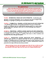
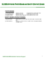
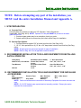
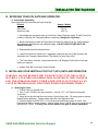
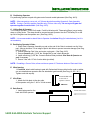
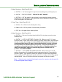
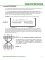
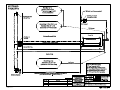
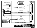
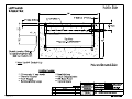
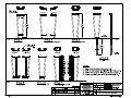
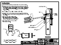
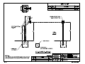
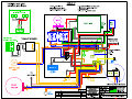
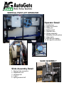
INSTALLATION
AND
INSTRUCTION MANUAL
* VPL-24/UL *
7306 Driver Road
P.O. Box 50
Berlin Heights, OH 44814
1.800.944.4283
Fax: 419.588.3514
www.AutoGate.com
Table of Contents
SAFETY INSTRUCTIONS
2
INSTALLATION CHECK OFF LIST
3
UL 325 SAFETY RECOMMENDATIONS
4
UL 325 SAFETY CLASSIFICATIONS
5
UL 325 PRIMARY AND SECONDARY ENTRAPMENT PROTECTIONS
6
UL 325 APPROVED PHOTO BEAMS AND SAFETY EDGES
7
INSTALLATION SAFETY INFORMATION
8
INSTALLATION: SITE PREP
9
INSTALLATION: TOOLS AND EQUIPMENT
9
INSTALLATION: RECEIVING YOUR VPL GATE AND OPERATOR
10
INSTALLATION: INSTALLING YOUR VPL GATE AND OPERATOR
10
INSTALLATION: OPERATOR WIRING AND TESTING
12
INSTALLATION: CONTROL BOARD
14
INSTALLATION: MASTER/ SLAVE WIRING
17
TROUBLESHOOTING
18
MANUAL OPERATION
19
MAINTENANCE
19
MAINTENANCE: BALANCING YOUR VPL
20
MAINTENANCE: BOARD REPLACEMENT
20
ACCESSORY INSTALLATION GUIDE
21
CONTACT INFORMATION
23
SAFETY INSTRUCTIONS
WARNING!
TO REDUCE THE RISK OF INJURY
OR DEATH, READ AND FOLLOW ALL
INSTRUCTIONS!
1. Never let children operate or play with gate controls. Keep the remote control
away from children.
2. At NO time should the gate panel be modified in any way. Any mounted signs
should weigh less than 4 lbs.
3. Always keep people and objects away from the gate. NO PERSON NOR
OBJECT SHOULD CROSS THE PATH OF THE MOVING GATE.
4. Test the gate operator monthly. The gate MUST reverse on contact with a rigid
object or stop when an object activates the non-contact sensors. After
adjusting the force or the limit of travel, reset the gate operator. Failure to
adjust and reset the gate operator properly can increase the risk of injury or
death.
5. Use the belt tension lever release only when the gate is not moving and
powered down.
6. KEEP GATES PROPERLY MAINTAINED. Read the owner’s manual. Have a
qualified service person make repairs to gate hardware.
7. The entrance is for vehicles only. PEDESTRIANS MUST USE A SEPARATE
ENTRANCE.
SAVE THESE INSTRUCTIONS.
1.800.944.4283 AutoGate Technical Support
2
INSTALLATION CHECK OFF SHEET
UL 325 COMPLIANT VPL-24
INSTALLATION CHECK OFF LIST
THIS GATE OPERATOR IS INSTALLED FOR USE AS A CLASS ______
INSTALLATION.
EACH ITEM ON THIS INSTALLATION CHECKOFF LIST MUST BE DISCUSSED
WITH THE CUSTOMER. A COPY SIGNED BY BOTH THE INSTALLER AND
CUSTOMER MUST BE RETURNED TO AUTOGATE. SIGNATURES INDICATE
UNDERSTANDING OFF ALL SAFETY ASPECTS LISTED BELOW.
____ FOUR WARNING SIGNS SECURELY INSTALLED ON EACH SIDE OF GATE PANEL.
(REQUIRED)
____ 1 OR 2 SAFETY/REVERSING PHOTO BEAMS INSTALLED, ONE ACROSS EACH SIDE OF
GATE OPENING.
____ TWO 12 VDC BATTERIES INSTALLED (REQUIRED) DEEP CYCLE MARINE RECOMMENDED.
____ CUSTOMER ADVISED THAT GATE IS FOR VEHICULAR TRAFFIC ONLY. (REQUIRED)
____ A SEPARATE PEDESTRIAN ENTRY AND/OR EXIT IS PROVIDED. (REQUIRED)
____ GATE GUARD INSTALLED ON BACK SIDE OF OPERATOR. (REQUIRED)
____ KICK PLATE INSTALLED ON DOOR SIDE OF OPERATOR. (REQUIRED)
____ ARE ALL ACTUATING CONTROLS LOCATED FAR OUT OF REACH OF GATE. (REQUIRED)
____ IS THIS CLASS OPERATOR APPROVED FOR THE APPLICATION OF THE OPERATOR
(CLASS 1,2,3,4,) (REQUIRED)
____ ARE CONTROLS TO RESET GATE AFTER OBSTRUCTED INSTALLED IN LINE OF
SIGHT.(REQUIRED)
____ HARD WIRED CONTACT SENSORS LOCATED & WIRED TO AVOID ANY MECHANICAL
DAMAGE.
____ FIELD WIRING SECURED TO AVOID PINCHING DAMAGE.
____ CUSTOMER INSTRUCTED AND IS CLEAR ON PROPER USE OF GATE OPERATOR.
(REQUIRED)
____ CUSTOMER INSTRUCTED ON PROPER USE OF ALL CONTROL SEVICES USED WITH
OPERATOR.
____ SAFETY INSTRUCTIONS WERE REVIEWED AND LEFT WITH CUSTOMER. (REQUIRED)
____ DID INSTALLER OFFER A PREVENTATIVE SERVICE / MAINTENANCE CONTRACT.
____ A PHOTO OF COMPLETED INSTALLATION TAKEN FROM FRONT AND BACK OF GATE &
DATED.
____ CUSTOMER TRAINED ON MANUAL OPERATION OF THE GATE.
_____________________________
CUSTOMER’S SIGNATURE
__________________
DATE
_____________________________
INSTALLER’S SIGNATURE
__________________
DATE
CUSTOMER & INSTALLER MUST RETAIN A COPY OF THIS CHECK OFF LIST FOR THEIR RECORDS
1.800.944.4283 AutoGate Technical Support
3
UL 325 SAFETY RECOMMENDATIONS
Automatic gate operators can produce high levels of force, therefore it is very important that all gate
operator system installers and designers are fully aware of potential hazards that exist with an
incorrectly installed or designed system. The internal safety capabilities of a gate operator system
are not enough to reduce the risk of injury. The operator is only one part of a properly installed
system which when combined with correctly installed safety/reversing devices will yield a complete UL
325 compliant system that will not only provide convenience and security, but will be safer with a
minimal risk of injury.
The following information along with the check list on page three and the rest of this manual is provided
to make you aware of potential areas that are of a safety concern. Disregarding any of the following may
result in serious injury or death.
•
•
•
•
•
•
•
•
•
•
•
•
•
•
•
•
•
•
•
•
FOUR WARNING SIGNS SECURELY INSTALLED ON EACH SIDE OF GATE PANEL
(REQUIRED).
1 OR 2 SAFETY PHOTO BEAMS INSTALLED, ONE ACROSS EACH SIDE OF GATE
OPENING.
PHOTO BEAMS INSTALLED ACCORDING TO THEIR INSTRUCTIONS & IN AREAS THAT
POSE ENTRAPMENT RISK.
CUSTOMER ADVISED THAT GATE IS FOR VEHICULAR TRAFFIC ONLY (REQUIRED).
A SEPARATE PEDESTRIAN ENTRY AND/OR EXIT IS PROVIDED (REQUIRED).
GATE GUARD INSTALLED ON BACK SIDE OF OPERATOR (REQUIRED).
KICK PLATE INSTALLED ON DOOR SIDE OF OPERATOR (REQUIRED).
ALL ACTUATING CONTROLS LOCATED FAR OUT OF REACH OF GATE (REQUIRED).
CLASS OF OPERATOR APPROVED FOR THE APPLICATION OF THE OPERATOR (CLASS
1,2,3,4) (REQUIRED)
CONTROLS INTENDED TO RESET GATE AFTER OBSTRUCTED INSTALLED IN LINE OF
SIGHT (REQUIRED).
HARD WIRED CONTACT SENSORS LOCATED & WIRED TO AVOID ANY MECHANICAL
DAMAGE.
FIELD WIRING SECURED TO AVOID PINCHING DAMAGE.
CUSTOMER INSTRUCTED AND IS CLEAR ON PROPER USE OF GATE OPERATOR
(REQUIRED).
CUSTOMER INSTRUCED ON PROPER USE OF ALL CONTROL SEVICES USED WITH
OPERATOR.
SAFETY INSTRUCTIONS WERE REVIEWED AND LEFT WITH CUSTOMER (REQUIRED).
INSTALLER OFFER A PREVENTATIVE SERVICE / MAINTENANCE CONTRACT.
A PHOTO OF COMPLETED INSTALLATION TAKEN FROM FRONT AND BACK OF GATE &
DATED.
ADVISED CUSTOMER THAT FOR MANUAL OPERATION, THEY MUST DISCONNECT
BATTERIES & AC POWER.
CUSTOMER IS TRAINED ON MANUAL OPERATION OF THE GATE.
DO NOT DISCONNECT THE SIREN IN ANY WAY – SWITCH S1#6 MUST STAY ON & S1#8
MUST STAY OFF. TAMPERING WITH THE SIREN SWITCH SETTINGS MAY POSE THE
RISK OF SERIOUS INJURY OR DEATH.
1.800.944.4283 AutoGate Technical Support
4
UL 325 SAFETY CLASSIFICATIONS
WARNING!
THE GATE OPERATOR IS DESIGNED AND FACTORY BALANCED FOR THE
SPECIFIC GATE IT WAS SUPPLIED WITH. IT IS NOT SAFE TO MODIFY THE GATE
IN ANY WAY OR ADD SIGNS WEIGHING MORE THAN 2LBS TOTAL. FAILURE TO
COMPLY WITH THIS REQUIREMENT WILL VOID THE WARRANTY AND MAY
RESULT IN SERIOUS INJURY OR DEATH.
CLASS I - RESIDENTIAL VEHICULAR GATE OPERATOR – A vehicular gate
operator (or system) intended for use in a home of one to four single family
dwelling, or a garage or parking area associated therewith.
CLASS II – COMMERCIAL / GENERAL ACCESS VEHICULAR GATE OPERATOR
– A vehicular gate operator (or system) intended for use in a commercial
location or building such as a multi-family housing unit (five or more single
family units), hotel, garages, retail store, or other buildings servicing the
general public.
CLASS III – INDUSTRIAL / LIMITED ACCESS VEHICULAR GATE OPERATOR –
A vehicular gate operator (or system) intended for use in an industrial location
or building such as a factory or loading dock area or other locations not
intended to service the general public.
CLASS IV - RESTRICTED ACCESS VEHICULAR GATE OPERATOR – A
vehicular gate operator (or system) intended for use in a guarded industrial
location or building such as an airport security area or other restricted access
locations not servicing the general public, in which unauthorized access is
prevented via supervision by security personnel.
THESE INSTRUCTIONS ARE INTENDED FOR THE INSTALLATION OF THE
UL 325 CERTIFIED AUTOGATE MODEL VPL-24 ONLY AND SHOULD NOT
BE SUBSTITUTED FOR THE INSTALLATION OF OTHER OPERATORS.
1.800.944.4283 AutoGate Technical Support
5
UL 325 PRIMARY AND SECONDARY ENTRAPMENT PROTECTION
SAFETY INSTRUCTIONS REGARDING PRIMARY & SECONDARY
ENTRAPMENT PROTECTION.
THIS UNIT IS PROVIDED WITH TWO MEANS OF ENTRAPMENT PROTECTION. (SEE UL-325 SECTION 30)
(A GATE OPERATOR SHALL PROVIDE 1 PRIMARY (INHERENT) AND 1 SECONDARY ENTRAPMENT
FEATURE).
PRIMARY: TYPE A – INHERENT ENTRAPMENT SENSING SYSTEMS
THE VPL-24 WILL REVERSE DIRECTION WHEN THE INHERENT TYPE A DEVICE SENSES AN
OBSTRUCTION.
SECONDARY: TYPE B1 – PROVISION FOR CONNECTION OF A NON-CONTACT SENSOR
(PHOTOELECTRIC OR THE EQUIVALENT.
(NOTE: UNIT SHIPS WITH S1-6 ON & S1-8 OFF. DO NOT CHANGE THESE SETTINGS)
PRIMARY PROTECTION DESIGNATED TYPE A INHERENT PROTECTION. UNIT WILL REVERSE DIRECTION
WHEN AN OBSTRUCTION IS SENSED WHILE MOVING IN EITHER DIRECTION. SENSITIVITY IS ADJUSTED
ARE IRD1 ON CONTROL BOARD. WHILE CLOSING IF A OBSTRUCTION IS SENSED BY THE PRIMARY
INHERENT SENSOR, THE GATE WILL REVERSE AND OPEN TO THE FULL OPEN POSITION. THE GATE
WILL REMAIN THERE UNTIL A CLOSE COMMAND IS RECEIVED OR WILL CLOSE BY TIMER AFTER NEW
INPUT IS RECEIVED. IN ORDER FOR THE GATE TO CLOSE BY TIMER (IF ACTIVATED) A NEW INPUT ON
TERMINALS J5 1-8 MUST BE GIVEN. IF AN INPUT STILL PRESENT WHEN THE GATE REACHED THE FULL
OPEN POSITION, THIS INPUT WILL NEED TO BE RENEWED OR REMOVED AND ANOTHER INPUT GIVEN
BEFORE THE CLOSE TIMER WILL CLOSE THE GATE.
ENTRAPMENT ALARM WILL ACTIVATE UPON THE PRIMARY INHERENT SENSOR SENSING A SECOND
OBSTRUCTION BEFORE REACHING A LIMIT SWITCH. ONCE ACTIVATED, GATE WILL REMAIN AT REST
ALARM WILL SOUND. THIS CONDITION CAN ONLY BE CLEARED BY AN INPUT APPLIED TO J5#4. THE
WIRING USED TO RESET THE OPERATOR MUST BE IN THE LINE OF SIGHT AND MUST BE AN
“INTENDED” RESET. ACCESS CONTROL DEVICES OF ANY KIND THAT REQUIRE AN INTENDED (ON
PURPOSE) ACTIVATION MAY BE USED FOR THIS RESET. DEVICES THAT WILL CAUSE AN INCIDENTAL
RESET (VEHICLE DETECTORS, PROBES, TIMERS, MOTION SENSORS, PHOTO BEAMS, ECT…) MUST
NOT BE USED. FAILURE TO COMPLY WITH THIS REQUIREMENT MAY RESULT IN SERIOUS
INJURY OR DEATH.
IMPORTANT!
The secondary entrapment device
must comply with UL 325, 4th
edition effective criteria of March 1,
2000.
1.800.944.4283 AutoGate Technical Support
6
UL 325 APPROVED PHOTO BEAMS AND SAFETY (CONTACT) EDGES
PHOTO BEAMS
1) EMX INDUSTRIES
2) ALLEN BRADLEY
3) OMRON / MMTC
MODEL#: IRB-325
TRANSMITTER / RECEIVER TYPE
MODEL#: 60-2728
RETRO-REFLECTIVE TYPE
MODEL#: E3K-R10K4-NR RETRO-REFLECTIVE TYPE
SAFETY EDGES (CONTACT EDGES)
1) MILLER EDGE
2) TAPE SWITCH
MODEL-MU-22, MG-020, ME-123, MC-22, ME-113, ME-120, ME020
MODEL IL, 107-RS, 107-LS, 121-BP, 101-B1, 102-A&B, 102-BHP,
101-BMT,101-B
1.800.944.4283 AutoGate Technical Support
7
INSTALLATION SAFETY INFORMATION
WARNING!
TO REDUCE THE RISK OF INJURY
OR DEATH, READ AND FOLLOW ALL
INSTRUCTIONS!
Proper design is important in your system layout and installation. Reversing/Safety devices
must be used at all available points where injury or property damage may occur. For
protection from injury to persons, use Photo Electric Eye or optional Pressure Sensing Edge
on the leading edge of the gate. Reversing/Safety Loops (Vehicle Detectors) should be
installed in front of and behind the gate to provide a reverse signal or stop signal to the gate
operator. All Reversing/Safety devices should be tested and inspected weekly. If a
Reversing/Safety device appears to not operate correctly, the unit should be disabled until
repair can be made by a properly trained/experienced service company.
As the system designer/installer, you must advise your customer/end user on the correct
usage of the gate operator and the system. In providing the service of design/installation of
the operator and system, you are responsible for proper training of the customer as well as for
the proper SAFE OPERATION. All precautions to eliminate ALL hazards MUST be taken
before the unit can be put into operation. You MUST advise and warn your customer of any
hazards that remain or if they choose not to use any of the recommended reversing/safety
devices in the installation.
•
•
•
•
•
•
•
•
If you did not order a Reversing/Safety Edge (for along the bottom rail of your gate), or an Infra-Red
Modulated Photocell (Reversing/Safety Beam), you will not be in compliance with March 2000 UL 325
Code. Consult your dealer for additional information.
Pedestrians must use a separate entrance/exit and not the vehicular entrance/exit gate.
NEVER activate the gate from long distances where visibility of the gate cannot be seen. Anyone
operating the gate should always operate it in a safe manner.
NEVER allow children or anyone to play on or around the gate at any time.
DO NOT affix any adhesive material within 30 days of receipt.
DO NOT attach anything to gate over 4 pounds total weight without consulting the factory re-balancing
instructions.
The gate must remain balanced to ensure safe and reliable operation.
The gate and operator are designed to work together. Do not attempt to install an unauthorized gate
without factory authorization.
DO NOT ALLOW any Access Control Devices to be mounted within 6 feet of the moving gate or in such
a way that someone could reach their hand or arm through to gate to activate it.
1.800.944.4283 AutoGate Technical Support
8
INSTALLATION INSTRUCTIONS
NOTE: Before attempting any part of the installation, you
MUST read the entire Installation Manual and Appendix A.
I. SITE PREPARATION:
A. Concrete Pads
Concrete pads are required to install your VPL Operator, Yoke & Gooseneck.
If applicable, (See Dwg. #101). NOTE: Operator & Yoke pads MUST be poured on the same
grade and be level.
1. Contoured gate grades may be an exception; check your order.
2. Certain special yokes do not require a pad; check w/site Dwgs. for installation.
B. Operator Pad Options:
1. Full Pad, Minimum depth of 36" or below local frost line (See Dwg. #101).
2. 10"-12” thick pad with four (4) 12" dia. x 36" deep holes or below local frost line (See Dwg.
#101).
NOTE: All pads need to be level and smooth for ease of installation
NOTE: Refer to Dwg. #101 for all applicable conduit locations
II. RECOMMENDED INSTALLATION TOOLS AND EQUIPMENT FOR INSTALLING
GATE & OPERATOR
Lifting Strap
Hammer Drill, 1/2 & 5/8 Bits
Tape Measure
Hammer
Multi-Meter (DCV & AMPS)
Grease Gun, Lithium
Grease
Screwdriver Sets (Flat &
Phillips)
Level
½” Drive Socket Set:
9/16”, 3/4”, 15/16”, 1-1/8”
Open End Wrenches:
9/16”, 3/4”, 15/16”, 1-1/8”
III. RECOMMENDED INSTALLATION TOOLS AND EQUIPMENT FOR INSTALLING
ACCESSORIES
Wire
Cutters/Strippers
Chalk Line
Electrical Tape
Amp. Meter
Misc. Electrical
Connectors
Batteries
Misc. 18 Ga. Strand
Wire
NOTE: Refer to manufacturer’s instructions of Accessory Equipment for correct wire size and
type.
NOTE: (2) 12 VDC batteries are required and not normally provided. Deep cycle marine
batteries are recommended.
1.800.944.4283 AutoGate Technical Support
9
INSTALLATION INSTRUCTIONS
IV. RECEIVING YOUR VPL GATE AND OPERATOR:
A. Unloading & Unpacking
Gate weight per foot varies with gate style & height.
Product
Operator
Steel Gate
Aluminum Gate
Approx. Weight
1124 #
24# / Ft.
19# / Ft.
1. Have adequate equipment ready to unload your Gate & Operator safely (Forklift, Front End
Loader or Wrecker with Telescoping Boom, see below Lifting Gate & Operator).
2. Before removing your Gate and Operator from the truck, inspect it for any visible damage
and make sure the Gate Box was shipped upright. DO NOT DROP EITHER GATE OR
OPERATOR BOX!
3. Disassemble protective wooden frame.
4. Locate Door and Key switch keys, if applicable, located at the front of the Operator and
attached to the Transport /Maintenance (T/M) Safety Pin (See Dwg. #103).
5. The Transmitters, Antenna, ordered accessories, and Shipping Packet will be enclosed
inside your operator.
6. Unpack Gate Box in the same careful manner.
V. INSTALLING YOUR VERTICAL PIVOT LIFT (VPL) GATE AND OPERATOR:
WARNING: DO NOT REMOVE THE T/M SAFETY PIN UNTIL THE GATE IS
SECURELY ATTACHED AND OPERATOR IS FASTENED TO THE CONCRETE
PAD. THE OPERATOR ARM IS UNDER A GREAT DEAL OF TENSION & CAN
CAUSE EXTREME DAMAGE AND INJURY IF RELEASED PREMATURELY!
A. Attaching the Gate:
1. Position Gate on Operator Arm.
2. Use (1) 3/4 x 4” Bolt for the top connection. Use (4) 1/2 x 1-1/2" Bolts for the bottom
connection.
3. Insert the top bolt first and then the bottom (4) bolts finger tight. Be certain gate is properly
aligned before tightening. Tighten bottom bolts first, then tighten top bolt.
4. Locate Linkage Pivot Bolt (5/8" x 2-1/4") & lubricate with lithium grease or equal. Also
lubricate both sides of spacer washer. Attach Linkage Arm to Gate & snug up on nylon lock nut,
then back off 1/4 turn. You may have to push down on the gate to insert Linkage Bolt.
1.800.944.4283 AutoGate Technical Support
10
INSTALLATION INSTRUCTIONS
B. Positioning Operator:
For positioning operator on pad with gate center line and conduit placement (See Dwg. #101).
NOTE: Allow concrete to cure a min. of (3) three days before setting Operator & Gate Assembly.
NOTE: If using a Forklift to position Operator only, lift from sides only! Do not try to lift gate and
operator together from the side! (See Dwg. #103).
C. Lifting Gate & Operator:
To lift Gate & Operator, (Front End Loader, Forklift or Wrecker with Telescoping Boom) use a towing
strap or a lifting chain. The strap should be secured around Operator Arm and T/M Safety Pin or the
top rail of the gate near the operator arm. (See Dwg. #103).
NOTE: It is recommended to attach Gate to Operator Arm before lifting (for better balance), but it is
not mandatory.
D. Positioning Operator & Gate:
1. Place Gate & Operator Assembly on pad so the end of the Gate is centered over the Yoke
pad. Allow a minimum 3" from edge of pad to bolt holes to prevent concrete damage (See Dwg.
#101 & #102).
2. Position and align Pad Yoke and center under gate. (See Dwg. #101)
3. Secure Operator with (1) 5/8" dia. Wedge Bolt in rear; check alignment.
4. Install remaining (3) 5/8" dia. Concrete Anchor Bolts provided, level Gate & Operator on
pad, if necessary.
5. Secure Yoke with 1/2” dia. Anchor bolts (provided).
NOTE: If installing a Ground Yoke, allow a minimum space of 2" between bottom of Gate and Yoke.
E. Wind bracing:
1. If ordered, attach wind bracing to gate with Galvanized Nuts provided on the rods or cables;
one nut attached near operator and one attached at gate bracket (See Dwg. #I-105-1 & 2.).
Tighten each side equally.
F. Kick Plate:
1. Attach the kick plate to the door side
of the operator using the 5 - #12 x 3/4 tek screws.
G. Gate Guard:
1. Install gate guard on the
back side of the operator.
1.800.944.4283 AutoGate Technical Support
Fasten KICKPLATE
to door side of
operator as shown.
Fasten Gate Guard
11
INSTALLATION INSTRUCTIONS
H. Additional Signage Installation:
We recommend any additional signage be installed between the operator and the center of the gate.
The total weight cannot exceed 4 pounds.
Factory Installed Warning Signs
IV. OPERATOR WIRING & TESTING
Additional Signage Installed Here
NOTE: Refer to electrical block diagram for additional information.
A. Connecting AC Power
NOTE: The A/C Power must be connected by a qualified, licensed Electrician, according to the
National Electric Code, and all State and local codes.
WARNING: TO REDUCE THE RISK OF ELECTRICAL SHOCK, THIS EQUIPMENT HAS A
GROUNDING TYPE PLUG THAT HAS A THIRD (GROUNDING) PIN. THIS PLUG WILL ONLY
FIT INTO A GROUNDING TYPE OUTLET. IF THE PLUG DOES NOT FIT IN THE OUTLET,
CONTACT A QUALIFIED ELECTRICIAN TO INSTALL THE PROPER OUTLET. DO NOT
CHANGE THE PLUG IN ANY WAY.
1. Turn Off DC power.
2. Wire incoming AC power to the 4 x 4 Box provided and turn on the breaker from your AC
Source.
3. Turn AC Power Switch on at the
4 x 4 Box.
Pre-Mounted 120vac Electrical Outlet &
AC Power Switch electrical connection
Additional 120 VAC Surge Protection is
recommended but not required. Surge
unit must be grounded to a true earth
ground.
Warning!
ON
OFF
Operator Main
AC Power Switch
(pre-wired to outlet)
120 VAC (Black) (BRASS terminal)
Green (Ground)
AC Outlets are HOT at
all times. Outlets are
for service use only.
A/C Electrical Supply
Minimal requirements:
120 vac, 15amp circuit
Neutral (White) (SILVER terminal)
WARNING: OPERATOR MUST BE GROUNDED TO TRUE EARTH GROUND LUG LOCATED ON
FRAME (See Dwg. # 103)
1.800.944.4283 AutoGate Technical Support
12
INSTALLATION INSTRUCTIONS
B. Connecting Batteries - Required
WARNING: Do not attempt to connect Batteries or power-up Gate & Operator
until all Accessories have been completely connected & checked. This will prevent
an accidental “short” of your system while wiring accessories.
1. Install (2) 12 VDC Batteries (not always include; check your order) on the battery shelf.
See drawing below for proper hook up. Use minimum 7 AH batteries for minimal battery back up
or deep cycle marine batteries for extended battery back up.
NOTE: Battery back up operation will depend on the size of batteries and / or the number of
accessories powered by the batteries.
2. Install Jumper Wire (provided) from Batt. #1 - POSITIVE to Batt. #2 - NEGATIVE (See
Below).
3. Locate RED and BLACK Power Wires and connect:
BLACK TO BATT. #1 - NEGATIVE
12 VDC Battery
Black Lead
Jumper
12 VDC Battery
Red Lead
RED TO BATT. #2 - POSITIVE
C. Testing
1. Remove T/M Safety Pin from front of Operator and hang it on the hook provided inside
access door.
NOTE: It may be necessary to push down on end of gate in order to take pressure off T/M
Safety Pin.
2. Temporarily remove any wires in the main circuit board Terminal #5 (rev. / safety) to disable
any Reversing/Safety devices not installed from preventing the gate from closing. (See Board
Dwg. #113)
3. Turn Main DC Power Switch “on”. (Located under the Control Box) Use a hand-held
transmitter or the Push Button (not on all models, See Dwg. #103) to test your gate system.
The push button located on the end panel is controlled by the toggle switch mounted at bottom
of Control Box (See Dwg. #103).
NOTE: Your gate should activate and open in approximately 10-12 seconds. If your gate does
not lift properly, refer to "Troubleshooting Tips".
1.800.944.4283 AutoGate Technical Support
13
INSTALLATION INSTRUCTIONS
4. If a key switch has been installed (below the push button), the key is removable from the
switch in either the "on" or "off" position.
5. Your gate operator was supplied with four factory installed WARNING signs. These signs
MUST be visible. Should your customer reject the usage of the standard warning signs, you
are strongly advised to have them sign a disclaimer.
D. Accessory Wiring (Ref. Electrical block diagram for additional information)
1. Turn off AC & DC power switches while connecting accessory wiring.
2. Reattach ALL wires removed from main circuit board Terminal #5 (safety/reversing).
3. Complete the wiring & testing of each accessory component one at a time. SEE
OPTIONAL ACCESSORIES INSTALLATION INSTRUCTIONS on page 21.
For example, to test the Safety/Reversing Beam, interrupt the beam when the gate is on the
way down. The gate should stop and reverse when the beam has been broken or interrupted.
Do the same for the Loops, Keypads, etc.
V. CONTROL BOARD
Your VPL gate has many features and options. Most are controlled by an electronic circuit board inside the
Control Box. Your circuit board is factory-set and should not be altered in any way or the Warranty may be
voided. If an adjustment has to be made, consult your “Gate Board Instructions” for details. If you need any
further assistance, please contact your local AutoGate Dealer or call AutoGate at 1-800-944-4283.
A. Timers and Mode Selections (S1 and S2)
1. Full Speed Run Timer – Switch Pack S1 (1-5)
Switches 1 through 5 are FACTORY PRESET.
PLEASE DO NOT CHANGE!
1
2
4
16 (Seconds)
ON
OFF
1
2
3
1-5 Fast Run Timer
1.800.944.4283 AutoGate Technical Support
8
4
5
6
7
8
6-8 Mode Selection
14
INSTALLATION INSTRUCTIONS
2. Mode Selections – Switch Pack S1 (6-8)
a. SWITCH 6 – “On” will energize K1 relay if someone attempts to push the gate open.
b. SWITCH 7 - FACTORY PRESET. PLEASE DO NOT CHANGE!
c. SWITCH 8 – “Off” will make K1 relay activate if not at closed limit switch (buzzers,
counters, etc.) “On” will make K1 relay pulse when OLS is reached for interface to open
a barrier arm gate in the same lane.
3. Close Timer – Switch Pack S2 (1-5)
a. Switches 1-5 on S2 are for the closing timer delay.
b. Default is S2-4 “ON” to provide a 8 second delay if activated.
c. If S2-7 is on, the gate will auto close by timer.
4. Mode Selections – Switch Pack (6-8)
a. SWITCH 6 – Sets aux. Open input terminal #4 at J5 to be pulse open-pulse close
(Default is On).
b. SWITCH 7 – AUTO CLOSE TIMER – Default is ON. When on, use S2 1-5 to set
close time delay. When close timer is selected, you MUST install vehicle and pedestrian
detection devices. It is strongly recommended that photoelectric beams (eyes) be
installed on BOTH sides of the gate to reduce the possibility of injury to persons
that may attempt to walk through the gate opening. Along with the beams, it is
strongly recommended that pressure-sensing edges be installed at the leading
edge of the gate panel, and at any area that may present a PINCH POINT or
provide a risk of ENTRAPMENT.
c. SWITCH 8 – AUTO OPEN ON POWER FAILURE – When switch 8 is in the ON
position, the operator will automatically open the gate approximately 15 seconds after
the loss of power. Once power is restored, the operator will resume normal operation.
Factory setting is “OFF” allowing the operator to function normally until the battery power
has diminished. Once A/C has been restored, the operator will function normally.
Note: If batteries were completely discharged, remove from operator and recharge with
a commercial grade battery charger.
1.800.944.4283 AutoGate Technical Support
15
INSTALLATION INSTRUCTIONS
B. Instant Reverse Device (IRD)
The instant reverse device is an internal circuit that continuously monitors the motors current for
increase draw. This is factory preset for your specific gate size. To test for proper operation, position
yourself approximately 2/3 of the way across the driveway. With the gate descending, catch the gate
and it should stop and reverse within two (2) seconds. If the gate does not reverse, call the factory for
technical assistance. If obstructed while closing, the gate will stop and reverse to the open position,
time out (using the time delay set at S2 switches 1-5) and then close. If gate is opening when
obstructed, the gate will stop its open travel. If inputs are present, gate will remain stopped. If no
inputs are present or existing are cleared, the gate will time out and close.
WARNING: INSTANT REVERSE DEVICE (IRD) SHOULD BE TESTED WEEKLY TO
INSURE PROPER OPERATION.
C. Barrier Gate Access Manager Interface
For full logical interface of AutoGate VPL to a barrier gate will require only two wires from the VPL gate
control panel to the barrier. Run two wires from the VPL panel NO and COMMON terminals at J1 to
the two LOW VOLTAGE raise gate terminals on the barrier gate. Next, switch on S1-8 to enable the
relay to pulse open the barrier arm gate. When operator reaches open limit position, relay will pulse to
open barrier. If while VPL gate is still open and another open signal is sent to the VPL gate, the relay
will pulse again. If a constant open signal is on the VPL gate, then the relay will stay energized. For a
day/night mode of operation where you will require the VPL gate to be held open, connect that hold
open device to J5 AUX OPEN terminal #4. This will not pulse or hold the relay, but when an open
signal is sent to J5 OPEN terminals #1, 2 or 3, the relay WILL pulse to raise the barrier arm. Note that
while the VPL is closing and the SAFETY LOOP input is activated or the gate is OBSTRUCTED, the
VPL gate will reverse BUT WILL NOT PULSE THE INTERFACE RELAY to open the barrier arm.
1.800.944.4283 AutoGate Technical Support
16
INSTALLATION INSTRUCTIONS
VI. MASTER SLAVE WIRING
A. In a master/slave configuration, either unit can be the master. Choose one unit to be the master and
then direct all control wiring to it (also install vehicle detector and receivers in it).
B. At the MASTER any input (at J5) with control (detectors, receivers, keypads, timers, etc...)
wires to it must also be run to the same terminals of the slave. Along with these control wires, both
operators MUST share a common ground connection from chassis to chassis (or from common to
common , i.e. master gate J5 terminal #12 to slave gate J5 terminal #12).
EXAMPLE: If only open and close are used at master then three wires will run between gates.
EXAMPLE:
SLAVE-J5
MASTER- J5
C. If it is required that if one gate senses an obstruction, the other reverses also, then 3 additional
wires must be run between the master J3 and slave J3 as shown below. These connections are for
transmitting IRD (obstruction signals) between both units. This will allow the master or slave to inform
the other that a closing obstruction has occurred and for it to also reverse and open. SET switches on
S2, 1-8 the same on both gates.
MASTER - J3
IRD - OBSTRUCTION SIGNAL CONNECTIONS
THE CONNECTIONS TO THE LEFT MUST BE DONE IN ORDER FOR
GATE IRD'S TO WORK CORRECTLY. TERMINAL 1 OF MASTER MUST
GO TO TERMINAL 4 OF SLAVE AND TERMINAL 1 OF SLAVE MUST
GO TO TERMINAL 4 OF MASTER. TERMINAL 2 OF MASTER WILL GO
TO TERMINAL 2 OF SLAVE.
SLAVE - J3
1.800.944.4283 AutoGate Technical Support
17
TROUBLE SHOOTING
VII. TROUBLE SHOOTING
WARNING: DISCONNECT BATTERIES AND AC POWER BEFORE SERVICING
ANY MECHANICAL OR MOVING COMPONENTS!
A. BATTERY CHECKOUT – When the batteries become weak the gate can begin to run noticeably
slower. (NOTE: Batteries should only be checked when you are sure they have had adequate time to
fully charge.) Turn off the AC power and run gate for 5 to 10 cycles while observing low battery
indicator LED D12. If LED 12 comes ON, batteries are too weak to function properly. If LED 12 does
not light, then voltage should be checked as they still may be near failure. Correct voltage is
approximately 25.5VDC. (NOTE: If LED D12 does light, gate will open to conserve batteries in this test
or in a real power loss, even if mode switch 8 is on S2 is off.) Return of AC power will clear the low
battery indicator. If the batteries are not completely drained, you may have to charge the batteries as
they may be too weak. Correct charge voltage is 27.5 VDC with batteries not connected (adjustment is
at R63).
B. GATE WILL NOT CLOSE - Check for any active inputs, AC power loss, AC power switch is off or
weak batteries. Check that batteries are connected properly. Is switch S3 in “ON” position (this is
manual open switch). Check if S2 switch number 8 is in “ON” position and if AC power is lost, See LED
D14. Check LED D12, if lit and AC power is off, then batteries need to be charged or replaced.
C. GATE WILL NOT OPEN - Check for AC power loss at D14 (check AC power switch) and that
batteries are fully charged. Check fuses and if inputs are wired correctly, test S3 manual open switch.
D. GATE DEAD – NO OPERATION - Check LED D14 for AC power indication and check that AC
power switch is “ON”. Check LED D11 for Heart Beat pulses, if none and D14 (AC) & D5 (BRAKE) are
on, then gate has repeatedly sensed obstructions. Clear obstruction, then clear with next new input.
IRD (D2) LED is flashing, MRT (Maximum Run Timer) has expired. Gate was unable to reach the
closed limit switch. Check that fast run timer is set to run as long as possible.
E. FUSE(S) ARE BLOWN - F3 (10 AMP AC) AND/OR F4 (15 AMP DC) Check for shorts in wiring. If
F3 AC fuse is blown, then batteries may also be dead. If you continue to blow fuses and no apparent
shortages are visible, you most likely have a blown circuit board and it will need to be replaced.
WARNING: FOR CONTINUED PROTECTION AGAINST FIRE, ONLY REPLACE
WITH THE SAME TYPE AND RATING OF FUSE.
F. GATE CLOSES THEN REVERSES - See IRD adjustments, also check for obstacles in gate travel,
such as trees, sticks, etc. Charge voltage to batteries too low, adjust at R63. With batteries
disconnected, set to 27.5.
G. IRD OBSTRUCTION SIGNAL TO OTHER GATE NOT WORKING CORRECTLY Remove connector at J3, obstruct gate3, LED D13 should go off for a few seconds. This indicates
signal was transmitted. Be sure gate3s share a common ground.
H. GENERAL SERVICE Belt(s) loose or need(s) replacement. Charge voltage for batteries should be 27.5 VDC with batteries
disconnected (set at R63).
1.800.944.4283 AutoGate Technical Support
18
MAINTENANCE INSTRUCTIONS
VI. MANUAL OPERATION
A. Your VPL gate is easily operated manually in the event of total power or component failure.
1. Turn main power switches off (both A/C & D/C).
2. Release the belt tension lever located under the gear motor to remove the belt tension.
3. Position yourself in front of operator and lift up on Linkage Arm at the pivot point 1”-2”. (See
dwg. #103).
4. Walk out to end of gate and lift gate to the open position.
NOTE: It only takes 16 - 30 lb. of force to open gate. If more is required, contact your
dealer or factory.
5. Place the T/M pin through the bracket holes to prevent the gate from lowering.
6. Secure the belt tension lever in the locked position to re-apply tension to the belts.
VII. MAINTENANCE
The Basic electric and mechanical systems require only minimum routine maintenance. The following
items should be checked and serviced periodically depending on amount of use. (See Dwg. #103 for
lube locations).
ITEM
Grease pivot pins on Linkage Assembly
(“LUBRIPLATE ‘R’ LOW TEMP” Grease)
Grease all bearings (2) Operator Arm, (2) Bullwheel Shaft
Grease Chain Tension Bolt and Lube Chain
Check belts for wear and tightness
(Belt flex is 1/4” – 1/2” top & bottom between output sheave &
bullwheel)
Check battery water level, use distilled water only
(Not required on maintenance-free)
Clean snow/ice off of gate
(Bal. Correctly, gate will temporarily tolerate an add’l 10 lb. of
wt.)
Clean lenses on Photocells or Reflectors
RECOMMENDED
MAINTENANCE
10,000 cycles or 6 months
every 6 months
every 6 months
every 6 months
every 6 months
as needed
as needed
Lubricate (Graphite Oil) all lock cylinders
every 6 months
Check and verify proper operation of all secondary entrapment
devices.
every month
Check and verify proper operation of all primary reversing
feature. (see Section V, Item #2-A)
every week
1.800.944.4283 AutoGate Technical Support
19
MAINTENANCE INSTRUCTIONS
A. Balancing a Gate:
Four months after installation, then annually. It is recommended to check the balance of your VPL
Operator. It is mandatory to re-check the balance if you change spring(s). You can monitor it on the
amp meter installed on the control box door. It is recommended to follow the instructions below for
accurate balancing numbers using a commercial grade AMP meter.
1. Remove the wire nut on the RED motor lead and hook up one Amp Meter lead to the RED
wire and the other Amp Meter lead to the ORANGE wire. Cycle the gate up and down and
record the highest amp reading in both directions (reading should be in the 2.0 to 6.0 range).
The highest reading for both the up and down cycles should be very close to the same. If not,
you will have to adjust the SLIDE ASSY. (see Dwg. # 107).
2. Loosen the 1 1/8” nuts on either side of the Slide Assy. Angle on the Threaded Rod. If the
gate Amps are too high in the OPEN mode, move the Slide Assy. UP to help it OPEN. (This is
the most common adj. Made). If the gate is flying open and struggling to close, move the Slide
Assy. DOWN. Only adjust the Slide Assy. 1/4” (3 to 4 turns) at a time when adjusting. After
each adjustment, check your amp readings.
3. When you have the gate back in balance (within a half amp (.5) is minimal), tighten both nuts
on Slide Assembly threaded rod.
B. Board Replacement
1. Turn ALL power off (AC & DC) to the board.
2. Remove (slide off) J2 “Open & Close” Limit Switch Terminal strip.
3. Remove (slide off) Accessories 1 through 12 Terminal strip.
4. Carefully remove the wires for the 24vdc Acc. Power, Battery Power, AC Power & Motor wires.
5. Take the board off the Standoffs and remove the (2) mounting bolts and replace with your NEW
circuit board and put all wires & connections back in the same place.
6. Double check the D.I.P. switch settings to be sure they are the same as your original board.
1.800.944.4283 AutoGate Technical Support
20
ACCESSORY INSTALLATION
VIII. OPTIONAL ACCESSORIES INSTALLATION INSTRUCTIONS
(Your gate order may not have included any or all of these accessories)
CAUTION! Failure to completely install any Safety/Reversing Devices may cause your gate
to default Open. (Ex.: Hooking up your Loop Wires to the Socket Base while not having the
Detector plugged in, or having your IFR Receiver hooked up and not the IFR Transmitter.)
NOTE: Refer to electrical block diagram for additional information on all accessory wiring.
A. Reversing/Free Exit Loops and Detectors:
1. Locate your “Homerun” lead-in Loop wires and connect the Free Exit Loop to Socket
Base connections #7 & #8 (Free Exit Device).
2. Locate your “Homerun” lead-in Loop wires and connect the Reversing/Safety Loop(s)
to Socket Base connections #7 & #8. You can wire (2) two Safety Loops to (1) one
Socket Base (Safety Device). Check the loop instructions for proper phasing.
3. Plug in your Loop Detector in the pre-wired socket base(s).
B. Photoelectric Sensors:
Refer to page 7 of this guide for the list of UL 325 approved components and to the
manufacturer’s instructions for their proper installation.
1. Verify voltage compatibility, 24 VDC is required.
2. Connect signal wire N.O. (normally open) to terminal #5 on your control board.
3. Connect the ground wire to terminal 9, 10, 11 or 12 (commons).
4. Connect the power wires to the terminal strip located inside the control box.
C. Contact Sensor Edge:
Refer to page 10 of this guide for the list of UL 325 approved components and to the
manufacturer’s instructions for their proper installation.
1. Connect signal wire N.O. (normally open) to terminal #5 on your control board.
2. Connect the ground wire to terminal 9, 10, 11 or 12 (commons).
3. Be certain all wires are secured to prevent damage to the gate during operation.
D. Vehicle Sensor Probe (Car-Sense 101):
1. Locate the Car-Sense 101 Vehicle Sensing Probe either along the edge of the Exit
Drive or install in the pavement as shown on Dwg. # 108.
2. Once installed, run the 2-conductor cable to Socket Base connections #6, 7 & 8 (Free
Exit Device). Refer to manufacturer’s instructions for proper wiring.
3. Connect the power wires to the terminal strip located inside the control box.
4. Connect signal wire to an open terminal – 1, 2, 3.
5. Connect the ground wire to terminal 9, 10, 11 or 12 (commons).
6. Plug in you Car Sense Detector in the pre-wired socket base. Refer to Manufacturer’s
Instructions.
1.800.944.4283 AutoGate Technical Support
21
ACCESSORY INSTALLATION
E. Gate Auto Timer:
1. Install your timer in the electrical box.
2. Run the power wires to Terminal Strip main power (+ and - ).
3. Run connections 3 & 5 to your Free Exit connections on the Circuit Board #’s 1, 2 or
3 (Open) & 9, 10, 11 or 12 (Common). (Refer to Manufacturers Instructions).
F. Keypads:
1. Refer to your Keypad Manufacturers Instructions for complete wiring.
2. Run the power wires to Terminal Strip main power (+ and - ).
3. The N.O. & Common signal wires to open the gate need to be attached to the Circuit
Board #’s 1, 2 or 3 (Open) & 9, 10, 11 or 12 (Common) (Refer to Manufacturer’s
Instructions).
G. Card Readers:
1. Refer to your Card Reader Manufacturer’s Instructions for complete wiring.
2. Run the power wires to Terminal Strip main power (+ and - ).
3. The N.O. & Common signal wires to open the gate need to be attached to the Circuit
Board #’s 1, 2 or 3 (Open) & 9, 10, 11 or 12 (Common) (Refer to Manufacturer’s
Instructions).
4. We recommend using a grounding rod to minimize lightning damage.
H. Phone Systems:
1. Refer to your Phone System Manufacturers Instructions for complete wiring
2. Most phone systems require a dedicated power supply and therefore they may not
function during a power outage.
3. The N.O. & Common signal wires to open the gate need to be attached to the Circuit
Board #’s 1, 2 or 3 (Open) & 9, 10, 11 or 12 (Common) (Refer to Manufacturer’s
Instructions).
4. We recommend using a grounding rod to minimize lightning damage.
NOTE: Refer to Appendix A3 for approved UL 325 Compliant components.
1.800.944.4283 AutoGate Technical Support
22
CONTACT INFORMATION
AutoGate, Inc.
7306 Driver Road
P.O. Box 50
Berlin Heights, OH 44814
PH: 1.800.944.4283
FAX: 419.588.3514
www.AutoGate.com
1.800.944.4283 AutoGate Technical Support
23
VERTICAL PIVOT LIFT OPERATOR
1
2
3
Operator Detail
1. Control box
2. Open limit switch
3. Safety pin
4. Battery shelf
5. Operator arm
6. Spring assembly
7. Bullwheel & belt system
8. Gear motor
9. Belt tension release
10. AC input & outlet box
4
5
10
6
8
9
7
SLIDE ASSEMBLY
1
2
Slide Assembly Detail
1.
2.
3.
4.
5.
Spring chain connector
Adjustment rod
Locking nuts
T-bolt
Spring tension bolt
3
4
5
ELECTRICAL BOX DETAIL
1
Control Box Detail
9
2
3
4
10
5
1. Optional accessories
2. Loop detector socket bases
3. Board accessory inputs
4. Control board
5. Accessory power strip
6. Cycle counter
7. Pushbutton ON/OFF switch
8. DC main power ON/OFF switch
9. Amp meter
10. Surge board
6
7
8
OPTIONAL ACCESSORIES
Heavy Duty Locks
Indicating Lights
Radio Receiver
Antenna
New location
A/C Indicator Light
Photo Eye
7306 Driver Road, P.O. Box 50
Berlin Heights, OH 44814
PH: 1-800-944-GATE
FAX: 419-588-3514
Email: [email protected]
www.AutoGate.com