1
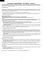
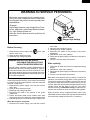
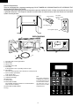
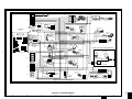
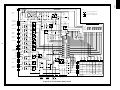
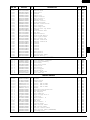
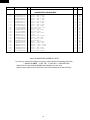
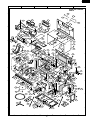
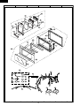
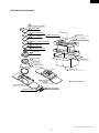
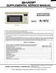
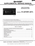
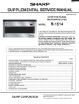
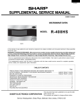
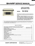
R-1874
SUPPLEMENTAL SERVICE MANUAL
S52M187R1874E
MIX CONV
DEFROST
SENSOR
TURNTABLE ON OFF COOK
LBS
OZ
KG
OVER THE RANGE
MICROWAVE OVEN
HELP
MODEL
R-1874
This is a supplemental Service Manual for Model R-1874.
This model is quite similar to Base Model R-1855A (S/M# S01M177R1875E).
Use this supplemental manual together with the Base Model Service Manual for complete operation and service information
In the interest of user-safety, the oven should be restored to its original condition and only parts identical to those specified
should be used.
WARNING TO SERVICE PERSONNEL: Microwave ovens contain circuitry capable of producing very high voltage and
current, contact with following parts may result in a severe, possibly fatal, electrical shock. (High Voltage Capacitor, High
Voltage Power Transformer, Magnetron, High Voltage Rectifier Assembly, High Voltage Harness etc..)
TABLE OF CONTENTS
Page
PRECAUTIONS TO BE OBSERVED BEFORE AND DURING SERVICE TO
AVOID POSSIBLE EXPOSURE TO EXCESSIVE MICROWAVE ENERGY ................... INSIDE FRONT COVER
BEFORE SERVICING ...................................................................................................... INSIDE FRONT COVER
MICROWAVE MEASUREMENT PROCEDURE .....................................................................................................1
WARNING TO SERVICE PERSONNEL..........................................................................................................3
FOREWORD ..........................................................................................................................................................4
PRODUCT SPECIFICATIONS ...............................................................................................................................5
GENERAL INFORMATION ...................................................................................................................................5
PICTORIAL DIAGRAM ..........................................................................................................................................7
CONTROL PANEL CIRCUIT ..................................................................................................................................8
PARTS LIST ..........................................................................................................................................................9
PACKING AND ACCESSORIES ......................................................................................................................... 15
This document has been published to be used for after sales service only. The contents are subject to change without notice.
SHARP ELECTRONICS CORPORATION
(IN USA):
Service Headquarters: Sharp Plaza, Mahwah, New Jersey, 07430-2135
OR:
(IN CANADA):
SHARP CORPORATION
SHARP ELECTRONICS OF CANADA LTD.
Head Office: 335 Britannia Road East, Mississauga, Ontario L4Z 1W9
(905) 890-2100
R-1874
PRECAUTIONS TO BE OBSERVED BEFORE AND
DURING SERVICING TO AVOID POSSIBLE
EXPOSURE TO EXCESSIVE MICROWAVE
ENERGY
(a) Do not operate or allow the oven to be operated with the door open.
(b) Make the following safety checks on all ovens to be serviced before activating the magnetron or other
microwave source, and make repairs as necessary: (1) interlock operation (2) proper door closing, (3)
seal and sealing surfaces (arcing, wear, and other damage), (4) damage to or loosening of hinges and
latches, (5) evidence of dropping or abuse.
(c) Before turning on microwave power for any service test or inspection within the microwave generating
compartments, check the magnetron, wave guide or transmission line, and cavity for proper alignment,
integrity, and connections.
(d) Any defective or misadjusted components in the interlock, monitor, door seal, and microwave
generation and transmission systems shall be repaired, replaced, or adjusted by procedures described
in this manual before the oven is released to the owner.
(e) A microwave leakage check to verify compliance with the Federal Performance Standard should be
performed on each oven prior to release to the owner.
BEFORE SERVICING (USA)
Before servicing an operative unit, perform a microwave emission check as per the Microwave
Measurement Procedure outlined in this service manual.
If microwave emissions level is in excess of the specified limit, contact SHARP ELECTRONICS
CORPORATION immediately @1-800-237-4277.
If the unit operates with the door open, service person should 1) tell the user not to operate the oven
and 2) contact SHARP ELECTRONICS CORPORATION and Food and Drug Administration's Center
for Devices and Radiological Health immediately.
Service personnel should inform SHARP ELECTRONICS CORPORATION of any certified unit found
with emissions in excess of 4mW/cm2. The owner of the unit should be instructed not to use the unit
until the oven has been brought into compliance.
BEFORE SERVICING (CANADA)
Before servicing an operative unit, perform a microwave emission check as per the Microwave
Measurement Procedure outlined in this service manual.
If microwave emissions level is in excess of the specified limit, contact SHARP ELECTRONICS OF
CANADA LTD. immediately.
If the unit operates with the door open, service person should 1) tell the user not to operate the oven
and 2) contact SHARP ELECTRONICS OF CANADA LTD. and NHW, CANADA immediately.
Service personnel should inform SHARP ELECTRONICS OF CANADA LTD. of any certified unit
found with emissions in excess of 4mW/cm2. The owner of the unit should be instructed not to use
the unit until the oven has been brought into compliance.
R-1874
MICROWAVE MEASUREMENT PROCEDURE (USA)
A. Requirements:
1) Microwave leakage limit (Power density limit): The power density of microwave radiation emitted by a microwave oven
should not exceed 1mW/cm2 at any point 5cm or more from the external surface of the oven, measured prior to acquisition
by a purchaser, and thereafter (through the useful life of the oven), 5 mW/cm2 at any point 5cm or more from the external
surface of the oven.
2) Safety interlock switches: Primary interlock relay and door sensing switch shall prevent microwave radiation emission in
excess of the requirement as above mentioned, secondary interlock switch shall prevent microwave radiation emission in
excess of 5 mW/cm2 at any point 5cm or more from the external surface of the oven.
B. Preparation for testing:
Before beginning the actual measurement of leakage, proceed as follows:
1) Make sure that the actual instrument is operating normally as specified in its instruction booklet.
Important:
Survey instruments that comply with the requirement for instrumentation as prescribed by the performance standard
for microwave ovens, 21 CFR 1030.10(c)(3)(i), must be used for testing.
2) Place the oven tray in the oven cavity.
3) Place the load of 275±15 ml (9.8 oz) of tap water initially at 20±5½C (68½F) in the center of the oven cavity.
The water container shall be a low form of 600 ml (20 oz) beaker with an inside diameter of approx. 8.5 cm (3-1/2
in.) and made of an electrically nonconductive material such as glass or plastic.
The placing of this standard load in the oven is important not only to protect the oven, but also to insure that any leakage
is measured accurately.
4) Set the cooking control on Full Power Cooking Mode
5) Close the door and select a cook cycle of several minutes. If the water begins to boil before the survey is completed,
replace it with 275 ml of cool water.
C. Leakage test:
Closed-door leakage test (microwave measurement)
1) Grasp the probe of the survey instrument and hold it perpendicular to the gap between the door and the body of the oven.
2) Move the probe slowly, not faster than 1 in./sec. (2.5 cm/sec.) along the gap, watching for the maximum indication on
the meter.
3) Check for leakage at the door screen, sheet metal seams and other accessible positions where the continuity of the
metal has been breached (eg., around the switches, indicator, and vents).
While testing for leakage around the door pull the door away from the front of the oven as far as is permitted by the closed
latch assembly.
4) Measure carefully at the point of highest leakage and make sure that the highest leakage is no greater than 4mW/cm2,
and that the secondary interlock switch does turn the oven OFF before any door movement.
NOTE: After servicing, record data on service invoice and microwave leakage report.
1
R-1874
MICROWAVE MEASUREMENT PROCEDURE (CANADA)
After adjustment of the door switches are completed individually or collectively, switch test and microwave leakage test must
be performed with survey instrument and test result must be confirmed to meet the requirement of the performance standard
for microwave ovens as undermentioned.
A. Requirements:
Every microwave oven shall function in such a manner that when the oven is fully assembled and operating with its service
controls and user controls adjusted to yield the maximum output, the leakage radiation, at all points at least 5 cm. from the
external surface of the oven, does not exceed:
1) 1.0mW/cm2 with the test load of 275 ± 15 ml of water at an initial temperature 20 ±5oC.
2) 5.0mW/cm2 when the outer enclosure is removed with a test load of 275 ± 15 ml of water at an initial temperature 20±5oC.
3) 5.0mW/cm2 without a test load.
B. Preparation for testing:
Before beginning the actual measurement of leakage, proceed as follows:
1) Make sure that the actual instrument is operating normally as specified in its instruction booklet.
Important:
Survey instruments that comply with the requirement for instrumentation as prescribed by CSA and NHW performance standard
for microwave ovens must be used for testing recommended instruments are , NARDA 8100 and NARDA 8200.
2) Place the oven tray in the oven cavity.
3) Place the load of 275±15 ml of tap water initially at 20±5oC in the center of the oven cavity.
The water container shall be a low form of 600 ml beaker with an inside diameter of approx. 8.5 cm (3-1/2 in.) and made
of an electrically nonconductive material such as glass or plastic.
The placing of this standard load in the oven is important not only to protect the oven, but also to insure that any leakage
is measured accurately.
4) Set the cooking control on Full Power Cooking Mode, Close the door and select a cook cycle of several minutes. If the water
begins to boil before the survey is completed, replace it with 275 ml of cool water.
C. Leakage test with enclosure installed :
1) Grasp the probe of the survey instrument and hold it perpendicular to the gap between the door and the body of the oven.
2) Move the probe slowly, not faster than 2.5 cm/sec. along the gap, watching for the maximum indication on the meter.
3) Check for leakage at the door screen, sheet metal seams and other accessible positions where the continuity of the metal
has been breached (eg., around the switches, indicator, and vents).
While testing for leakage around the door pull the door away from the front of the oven as far as is permitted by the closed
latch assembly.
4) Measure carefully at the point of highest leakage and make sure that the highest leakage is no greater than 4mW/cm2, and
that the secondary interlock switch does turn the oven OFF before any door movement.
C. Leakage test without enclosure:
1) Remove the enclosure (cabinet).
2) Grasp the probe of the survey instrument and hold it perpendicular to all mechanical and electric parts of the oven that is
accessible to the user of the oven including, but not limited to, the waveguide, cavity seams, magnetron gap between the
door and the body of the oven.
3) Move the probe slowly, not faster than 2.5 cm/sec. along the gap, watching for the maximum indication on the meter.
4) Measure carefully at the point of highest leakage and make sure that the highest leakage is under 5mW/cm2.
CAUTION: Special attention should be given to avoid electrical shock because HIGH VOLTAGE is generated during this test
No Load test
1) Operate the oven without a load and measure the leakage by the same method as the above test procedure " Leakage
test with enclosure installed"
2. Make sure that the highest leakage should not exceed 5mW/cm2.
NOTE: After servicing, record data on service invoice and microwave leakage report.
2
R-1874
WARNING TO SERVICE PERSONNEL
Microwave ovens contain circuitry capable of producing very high voltage and current, contact with
following parts may result in a severe, possibly fatal,
electrical shock.
(Example)
High Voltage Capacitor, High Voltage Power Transformer, Magnetron, High Voltage Rectifier Assembly, High Voltage Harness etc..
Read the Service Manual carefully and follow all
instructions.
Don't Touch !
Danger High Voltage
outer case.
2. Open the door and block it open.
3. Discharge high voltage capacitor.
4. Reconnect the leads to the primary of the power
transformer.
5. Reinstall the outer case (cabinet).
6. Reconnect the power supply cord after the outer case is
installed.
7. Run the oven and check all functions.
Before Servicing
1. Disconnect the power supply cord
remove outer case.
2. Open the door and block it open.
3. Discharge high voltage capacitor.
, and then
WARNING: RISK OF ELECTRIC SHOCK.
DISCHARGE THE HIGH-VOLTAGE
CAPACITOR BEFORE SERVICING.
After repairing
1. Reconnect all leads removed from components during
testing.
2. Reinstall the outer case (cabinet).
3. Reconnect the power supply cord after the outer case is
installed.
4. Run the oven and check all functions.
The high-voltage capacitor remains charged about 60
seconds after the oven has been switched off. Wait for
60 seconds and then short-circuit the connection of the
high-voltage capacitor (that is the connecting lead of the
high-voltage rectifier) against the chassis with the use of
an insulated screwdriver.
Microwave ovens should not be run empty. To test for the
presence of microwave energy within a cavity, place a cup
of cold water on the oven turntable, close the door and set
the power to HIGH and set the microwave timer for two (2)
minutes. When the two minutes has elapsed (timer at zero)
carefully check that the water is now hot. If the water
remains cold carry out Before Servicing procedure and reexamine the connections to the component being tested.
Whenever troubleshooting is performed the power supply
must be disconnected. It may in, some cases, be necessary
to connect the power supply after the outer case has been
removed, in this event,
1. Disconnect the power supply cord, and then remove
outer case.
2. Open the door and block it open.
3. Discharge high voltage capacitor.
4. Disconnect the leads to the primary of the power
transformer.
5. Ensure that these leads remain isolated from other
components and oven chassis by using insulation tape.
6. After that procedure, reconnect the power supply cord.
When all service work is completed and the oven is fully
assembled, the microwave power output should be checked
and microwave leakage test should be carried out.
When the testing is completed,
1. Disconnect the power supply cord, and then remove
3
R-1874
SUPPLEMENTAL
SERVICE MANUAL
PRODUCT DESCRIPTION
MICROWAVE OVEN
R-1874
GENERAL INFORMATION
FOREWORD
This Manual has been prepared to provide Sharp Electronics Corp.
Service Personnel with Operation and Service Information for the SHARP
MICROWAVE OVEN, R-1874.
OPERATION
WIRING DIAGRAM
The model R-1874 is quite similar to base model R-1855A
(Ref.# S99M138R1855E)
It is recommended that service personnel carefully study the entire text
of this manual and the base model's manual so that they will be qualified
to render satisfactory customer service.
Check the interlock switches and the door seal carefully. Special
attention should be given to avoid electrical shock and microwave
radiation hazard.
WARNING
Never operate the oven until the following points are ensured:
(A) The door is tightly closed.
(B) The door brackets and hinges are not defective.
(C) The door packing is not damaged.
(D) The door is not deformed or warped.
(E) There is no other visible damage with the oven.
Servicing and repair work must be carried out only by trained service
personnel.
DANGER
Certain initial parts are intentionally not grounded and present
a risk of electrical shock only during servicing. Service personnel - Do not contact the following parts while the appliance is
energized;
High Voltage Capacitor, Power Transformer, Magnetron, High
Voltage Rectifier Assembly, High Voltage Harness;
If provided, Vent Hood, Fan assembly, Cooling Fan Motor.
All the parts marked “*” on parts list are used at voltages more than
250V.
Removal of the outer wrap gives access to voltage above 250V.
USA MODEL
SHARP ELECTRONICS CORPORATION
SHARP PLAZA, MAHWAH,
NEW JERSEY 07430-2135
CANADIAN MODEL
OSAKA, JAPAN
4
PARTS LIST
R-1874
SPECIFICATION
ITEM
DESCRIPTION
Power Requirements
120 Volts / 13.2 Amperes (Microwave), 13.2 Amperes (Convection) - [UL Rating]
116 Volts / 13.0 Amperes (Microwave), 13.0 Amperes (Convection) - [CFS Rating]
60 Hertz
Single phase, 3 wire grounded
Power Output
850 watts (IEC-705 TEST PROCEDURE)
Operating frequency of 2450MHz
Convection Power Output
1400 watts
Case Dimensions
Width 29-15/16"
Height 16-11/32"
Depth 15- 9/32"
Cooking Cavity Dimensions
1.1 Cubic Feet
Width 17-1/8"
Height 8-1/16"
Depth 13-13/16"
Hood lamp
2 bulbs, 20W x 2, Incandescent light bulbs
Hood fan
Horizontal discharge 230 C.F.M. , Vertical discharge 240 C.F.M. ,
Control Complement
Touch Control System
Clock ( 1:00 - 12:59 )
Timer (0 - 99 min. 99 seconds)
Microwave Power for Variable Cooking
Repetition Rate;
P-HI ................................................... Full power throughout the cooking time
P-90 ..................................................................... approx. 90% of Full Power
P-80 ..................................................................... approx. 80% of Full Power
P-70 ..................................................................... approx. 70% of Full Power
P-60 ..................................................................... approx. 60% of Full Power
P-50 ..................................................................... approx. 50% of Full Power
P-40 ...................................................................... approx. 40% of Full Power
P-30 ...................................................................... approx. 30% of Full Power
P-20 ..................................................................... approx. 20% of Full Power
P-10 ....................................................................... approx. 10% of Full Powe
P-0 ...................................................... No power throughout the cooking time
CUSTOM HELP pad, SENSOR COOK pad, COMPU BROIL pad, COMPU ROAST pad
COMPU BAKE pad, SENSOR REHEAT pad, MINUTE PLUS pad, POPCORN pad
COMPU DEFROST pad, CONVECTION pad, REHEAT pad, LOW MIX/BAKE pad
HIGH MIX/ROAST pad, BROIL pad, SLOW COOK pad, KITCHEN TIMER pad
Number and temperature selection pads, CLOCK pad, KEEP WARM pad
TURNTABLE ON / OFF pad, POWER LEVEL pad, STOP/CLEAR pad,
START / TOUCH ON pad, Fan Hi/Lo, Light.
Oven Cavity Light
Yes 20W x 1 Incandescent light bulb
Safety Standard
UL Listed
FCC Authorized
DHHS Rules, CFR, Title 21, Chapter 1, Subchapter J
Canadian Standards Association.
Department of National Health and Welfare CANADA, Industry CANADA.
Weight
Approx. 71 lbs.
GENERAL INFORMATION
GROUNDING INSTRUCTIONS
This oven is equipped with a three prong grounding plug. It must be plugged into a wall receptacle that is properly installed and
grounded in accordance with the National Electrical Code and local codes and ordinances.
In the event of an electrical short circuit, grounding reduces the risk of electric shock by providing an escape wire for the electric
current.
WARNING:
Improper use of the grounding plug can result in a risk of electric shock.
5
R-1874
Electrical Requirements
The oven is equipped with a 3-prong grounding plug. DO NOT UNDER ANY CIRCUMSTANCES CUT OR REMOVE THE
GROUNDING PIN FROM THE PLUG.
The power supply cord and plug must be connected to a separate 120 Volt AC, 60 Hz, 15 Amp. or more branch circuit, using
a grounded receptacle. The receptacle should be located inside the cabinet directly above the Microwave Oven/Hood
system mounting location.
Grounded
Receptacle Box
3-Pronged Plug
Grounding Pin
3-Pronged Receptacle
OVEN DIAGRAM
9
1
8
3
6
13
2
4
5
10
7
6
14
12
1.
2.
3.
4.
5.
Oven door with see-through window.
Door hinges.
Stirrer cover.
Turntable motor shaft.
Oven lamp.
It will light when oven is operating or door is open.
6. Door latches.
The oven will not operate unless the door is securely closed.
7. One touch door open button.
Push to open door.
8. Auto-Touch control panel.
NOTE:
9. Ventilation openings.
Some one-touch cooking features
10. Light Cover.
as "MINUTE PLUS" are disabled af11. Grease filters.
ter one minute when the oven is not
12. Removable turntable.
used. These features are automatiThe turntable will rotate clockwise or counterclockwise.
cally enabled when the door is
opened and closed or the STOP/
Only remove for cleaning.
CLEAR pad is pressed.
13. Removable turntable support.
14. Plug
6
11
A
B
C
A
B
C
D
HOOD FAN MOTOR
BLK
6
BLK
5
4
3
6
YLW
BLK
2
WHT
BRN
GRN
1
PNK
N.O.
to oven cavity
front flange
RED
BLU
PPL
5 RED
4 YLW
3 WHT
2 BLK
GRY
1
GRN
COM.
Power Supply
cord 120V 60Hz
TEMPERATURE FUSE (MG.)
R
E
D
B
L
K
CONVECTION
MOTOR
2
2
2
2
BLK
GRN
BLK
2 WHT
1 GRN
GRN
WHT
DOOR SENSING SWITCH
3
GRY
BLU
STIRRER MOTOR
PNK
BLK
BLK
1
1
1
1
2 RED
GRN
RY2: PRIMARY
INTERLOCK
RELAY
D
E
F
G
H
1
CN-E
E
F
G
H
AH. SENSOR
3 WHT
CN-F
WHT
GRN
WHT
BLK
COM.
CN-G
CN-E
RED
PPL
2 BLK
1 BLK
THERMISTOR
YLW
T1
3
3
DAMPER
SWITCH
BRN
RY4
COM.
BRN
RY7
RY5
BLK
BLK
RY8
RY6
BLK
RED
BLK
N.O.
CN-F
RY10
CN-A
DAMPER
MOTOR
BRN
8
7
PPL
MAGNETRON
GRY
HIGH VOLTAGE
CAPACITOR
4
4
7
9
HIGH VOLTAGE COMPONENTS
N.O.
WHT
CN-B
WHT
GRY
3
3
RY1
YLW
OVEN LAMP & SOCKET
BLK
COM.
RY9
RED
BRN
RY2 N.O.
CN-C
Blue
Marking
MONITOR
FUSE AND
FUSE HOLDER
PPL
RY3 N.O.
COM.
CN-F
HEATING
ELEMENT
BLK
IC1
BLU
6
CN-C
F
BLU
BLK
2
7
WHT
PNK
N.C.
BLK
COM.
MONITOR
SWITCH
BLK
6
CN-B
5
4
3
BLU
H.V.
RECTIFIER
FAN
MOTOR
BLK
5
5
1
FA
4
4
5
4
3
BLK
GRY
WHT
POWER TRANSFORMER
RED
RED
2
1
GRY
ORG
WHT
COM.
GRY
SECONDARY
INTERLOCK
SWITCH
B
L
K
B
L
K
B
R
N
TURNTABLE
MOTOR
HOOD FAN
THERMAL
CUT-OUT
ORG
GRY
WHT
BRN
HOOD LAMPS
& SOCKETS
GRY
6
6
3 YLW
2
1 RED
2 GRY-GRY
1 BRN-BRN
5
5
CN-A
PNK
N.O.
5 GRY
4
BRN
Blue Marking
Figure S-1. Pictorial Diagram
A
B
C
D
E
F
G
H
6
6
R-1874
Figure S-1. Pictorial Diagram
A
B
C
D
E
F
G
H
A
B
C
D
E
F
G
H
R-1874
T1
C ONT R OL UNIT
5
C7
R 7 4.7k
ZD4
HZ4A2
D28
R 62 36kF
R Y3
R 30 15k
C 50
D32
C OM
Q28 K R A101M
D29
NO
R 31 4.7k
C F 1 4MHz
(A)
(B )
Q29 K R A101M
G 8
(C )
C 72 330pF
G 9
C 70 330pF
22
23
24
25
26
27
28
29
1G
2G
3G
4G
5G
6G
7G
8G
K G HE L P
5
6
7
8
9
10
11
12
13
15
16
17
18
19
20
R 93 100k
OZ
P2
P3
P4
P5
P6
P7
P8
P9
P 10
P 11
P 12
P 13
P 14
P 15
P 16
G 3
G 4
G 5
G 6
R 82 3.3k
D76
R 81
D75 3.3k
D74 3.3k
3.3k
R 80
R 79
R 78 3.3k
D71
G 2
G 7
C US T OM S E NS OR
HE LP
R E HE AT
C OMP U S E NS OR
MINUT E
P OP C OR N DE F R OS T
P LUS
C OOK
C OMP U
B R OIL
C ONV E C P R E HE AT
LOW MIX
B AK E
C OMP U
B AK E
G 10
B R OIL
S LOW
C OOK
G 11
K IT C HE N
T IME R
C LOC K
G 12
TUR NTABLE P OWE R
LE V E L
ON / OFF
C 71 330pF
D30
R 77 3.3k
R 76 3.3k
D70
G 1
C 74 330pF
C 73 330pF
D31
C OM
C 60
Q60
K R C 102M
R 74 3.3k
R 63 220F R 64 3.6
R 51 4.7k
C 30
C OOK L B S
1
100°F
6
HIG H MIX
R OAS T
2
150°F
7
C OMP U
R OAS T
3
275°F
8
4
300°F
9
5
5
R 50 15k
NO
R 75 100k
kF
R 70 3.3k
Q27
K R C 243M
C OM
R 73 3.3k
Q30
K R A101M
IC 1 IZA719DR
–
(A)
R 91 100k
R 92 100k
R 100 330 1w
C 11
(J 7)
(J 5)
+
(C ) (B )
R 72 3.3k
R Y1
+
R 65 1k
C 65
100µ/16v
P 30
P 31
P 32
P 33
P 34
P 35
P 36
P 37
P 00
P 01
P 02
P 03
P 04
P 05
P 06
P 07
P 10
P 11
P 12
P 13
P 14
P 15
P 16
P 17
P 20
P 21
P 22
P 23
P 24
P 25
P 26
P 27
R 71 3.3k
+
–
D65
D26
Q26 K R A101M
–
MIC R O
12
D73
C8
R 8 4.7k
C 12
10µ/35v
Q25 K R A101M
R Y2
C ONV E C T ION
HE R T E R
(J 3)
(J 6)
(J 4)
Q24 K R A101M
D27
NO
IC 2 IZA495DR
F
1, 2
MIX C ONV
F 31, 32
4 DE F R OS T
P1
S E NS OR
TUR NTAB L E ON OF F
(V P )
4
C7
VC C
VE E
AV S S
VR E F
AN7
AN6
AN5
AN4
AN3
AN2
AN1
AN0
P 55
P 54
P 53
P 52
P 51
P 50
P 47
P 46
P 45
P 44
P 43
P 42
INT 1
P 40
RST
P 71
P 70
XIN
XOUT
VS S
R Y 10
4
HIG H
C9
0.1µ/50v
Q23 K R A101M
R Y9
HOOD MOT OR
C5
1
R Y8
HOOD T HE R MO
LOW
R 40 3.3k
R Y7
D23
C9
C5
ZD3 HZ5C 2
C 4 10µ/35v
C 3 0.1µ/50v
ZD2
HZ16-1
–
D25
C3
F LUOR E S C E NT DIS P LAY T UB E
Q22 K R A101M
D24
8
C OM
S P 40
R Y6
(J 2)
C1
+
C 21 0.1µ/50v
HOOD LAMP
Q40
K R A101M
D22
B7
R 90 100k
3
3
C ONV E C T ION
MOT OR
Q21 K R A101M
C 10 0.1µ/50v
Q90 K R A101M
R Y5
C 20 10µ/35v
B3
: IF NOT S P E C IF IE E D, 0.01µF /16v
(V P )
Q3
K R A101M
R Y4
Q20 K R A101M
: IF NOT S P E C IF IE E D, 1S S 270A
R 4 510 1/2w
Q1 2S B1238
R 3 680 1w
D20
B1
B5
OV E N LAMP
–
A3
DAMP E R
MOT OR
C OM
(H)
R 1 4.3k
1/2w
C 100
D21
F AN MOT OR
–
+
Q4
DT A123E S
2
2
T UR NT AB LE
MOT OR
A1
D3
+
R 2 1.5k
(J 1)
MOT OR R UN
C AP AC IT OR
D2
: IF NOT S P E C IF IE E D, 1/4w ± 5%
D4
a
4
c
D1
ZD1
HZ6A3
b
3
C 1 0.1µ/50v
d
AC 120V
60Hz
NOT E
D1-D4 : 11E S 1
D72
6
2
1
1
1
C 2 1000µ/35v
A5
VR S 1
10G 471K
(N)
5
325°F
0
350°F
375°F
400°F
425°F
450°F
KE E P
WAR M
S T OP
C LE AR
S TAR T
TOUC H ON
F AN
HI/LO
LIG HT
K E Y UNIT
E1
E2
E3
E5
E4
E6
F1
F2
F3
6
DAMP E R
S WIT C H
6
AH S E NS OR
DOOR
S WIT C H
OV E N
T HE R MIS T OR
Figure S-2. Touch Control Panel Circuit
A
B
C
D
E
F
G
H
R-1874
PARTS LIST
"§" MARK: PARTS DELIVERY SECTION.
REF. NO.
PART NO.
§
DESCRIPTION
Q'TY CODE
ELECTRIC PARTS
1- 1
1- 2
1- 3
1- 4
1- 5
1- 6
1- 7
1- 8
1- 9
1-10
1-11
1-12
1-13
1-14
1-15
1-16
1-17
1-18
1-19
1-20
1-21
1-22
1-23
1-24
FH-DZB017MRY0
RC-QZA234WRE0
QFS-TA013WRE0
RHET-A174WRE0
RMOTDA211WRE0
RMOTDA241WRE0
RTHM-0044MRE0
RTRN-B070MRE0
RV-MZA302WRE0
QFSHDB003MRE0
QSW-MA085WRE0
FFS-BA018/KIT
FACCDB011MRE0
QSOCLB006MRE0
FH-HZA053WRE0
QSOCLB006MRE0
FMOTEA362WRK0
RMOTEA343WRE0
RMOTEB032MRE0
RLMPTA068WRE0
FDTCTA217WRKZ
RMOTDA242WRE0
RR-WZA031WRE0
FPWBFB014MRK0
M
M
M
M
M
M
M
M
M
M
M
M
M
M
M
M
M
M
M
M
M
M
M
M
High voltage rectifier assembly
High voltage capacitor
Temperature fuse 150°C
Convection heater
Turntable motor
Stirrer motor
Thermal cut-out N.O. 60°C
Power transformer
Magnetron
Fuse holder
Secondary interlock, third door sensing and damper switches
Monitor and sec. interlock switch with fuse assembly
Power supply cord
Hood lamp socket
Thermistor
Oven lamp socket
Hood fan motor
Convection motor
Fan motor
Hood lamp and oven lamp
AH sensor
Damper motor
Noise resistor
Noise filter
1
1
1
1
1
1
1
1
1
1
3
1
1
2
1
1
1
1
1
3
1
1
1
1
AM
AR
AG
AZ
AQ
AG
AG
BF
BC
AD
AE
AF
AP
AE
AP
AE
BM
AX
AW
AG
AW
AH
AK
AU
2
1
1
1
1
1
1
1
1
1
1
1
AF
AW
AH
AF
BC
AB
AM
AG
AH
AX
AL
AG
1
1
1
1
1
1
1
1
1
1
1
1
2
1
1
2
2
1
1
2
2
1
5
1
1
4
13
7
BQ
AC
AC
AC
AC
AD
AE
AV
AB
AB
AF
AB
AB
AB
AB
AH
AB
AB
AM
AH
AH
AH
AA
AM
AD
AB
AA
AA
CABINET PARTS
2- 1
2- 2
2- 3
2- 4
2- 5
2- 6
2- 7
2-7-1
2-7-2
2- 8
2- 9
2-10
PFIL-B002MRE0
FDIF-B013MRK0
GDAI-B052MRP0A
GDAI-B039MRP0A
GCABUB106MRP0
TMAPCB063MRR0
FANGKB009MRY0
LANGQB016MRP0
PGLSPB004MRE0
PCOVPB030MRT0A
FDECAB028MRK0
LSTY-B010MRP0
M
M
M
M
M
M
M
M
M
M
M
M
Grease filter
Hood exhaust louver
Base plate right
Base plate left
Outer case cabinet
Schematic diagram
Hood lamp glass assembly
Hood lamp glass angle
Hood lamp glass
Base cover
Sash left
Rear stay
3- 1
3- 1A
3- 1B
3- 1C
3- 1D
3- 1E
3- 1F
3- 1G
3- 1H
C1
C2
C3
C4,C12
C5
C6
C7-8
C9-10
C20
C21
C30,C5
C50,C11
C60
C70-74
C100
CF1
D1-4
D20-32
D70-76
DPWBFB061MRU0
QCNCMA227DRE0
QCNCMA230DRE0
QCNCMA234DRE0
QCNCMA267DRE0
QCNCMA237DRE0
QCNCWA030DRE0
RV-KXB003MRE0
PTPEHB010MRE0
RC-KZA087DRE0
VCEAB31VW108M
RC-KZA087DRE0
VCEAB31VW106M
RC-KZA087DRE0
VCEAB31VW106M
VCKYD11CY103N
RC-KZA087DRE0
VCEAB31VW106M
VCEAB31HW104M
VCKYD11CY103N
VCKYD11CY103N
VCKYD11CY103N
VCKYD11HB331K
RC-QZB014MRE0
RCRS-A010DRE0
VHD11ES1///-1
VHD1SS270A/-1
VHD1SS270A/-1
M
J
J
J
J
J
J
M
M
J
J
J
J
J
J
J
J
J
J
J
J
J
J
M
J
J
J
J
Control unit
3-pin connector CN-A
4-pin connector CN-B
5-pin connector CN-C
6-pin connector CN-E
3-pin connector CN-F
12-pin connector CN-G
Fluorescent display tube
Tape 2mm
Capacitor
0.1 uF
50V
Capacitor
1000 uF
35V
Capacitor
0.1 uF
50V
Capacitor
10 uF
35V
Capacitor
0.1 uF
50V
Capacitor
10 uF
35V
Capacitor
0.01 uF
16V
Capacitor
0.1 uF
50V
Capacitor
10 uF
35V
Capacitor
0.1 uF
50V
Capacitor
0.01 uF
16V
Capacitor
0.01 uF
16V
Capacitor
0.01 uF
16V
Capacitor
330 pF
50V
Capacitor
7 uF
230V
Ceramic resonator (CST4.00MGW)
Diode (11ES1)
Diode (1SS270A)
Diode (1SS270A)
CONTROL PANEL PARTS
9
R-1874
REF. NO.
IC1
IC2
Q1
Q3
Q4
Q20-26
Q27
Q28-30
Q40
Q60
Q90
R1
R2
R3
R4
R7-8
R30
R31
R40
R50
R51
R62
R63
R64
R70-74
R75
R76-82
R90-93
R100
RY1-3
RY4-9
RY10
SP40
T1
VRS1
ZD1
ZD2
ZD3
ZD4
3- 2
3- 2-1
3- 2-2
3- 2-3
3- 2-4
3- 2-5
3- 3
PART NO.
RH-IZA719DRE0
RH-IZA495DRE0
VS2SB1238//-3
VSKRA101M//-3
VSDTA123ES/-3
VSKRA101M//-3
VSKRC243M//-3
VSKRA101M//-3
VSKRA101M//-3
VSKRC102M//-3
VSKRA101M//-3
VRD-B12HF432J
VRD-B12EF152J
VRS-B13AA681J
VRD-B12HF511J
VRD-B12EF472J
VRD-B12EF153J
VRD-B12EF472J
VRD-B12EF332J
VRD-B12EF153J
VRD-B12EF472J
VRN-B12EK363F
VRN-B12EK221F
VRN-B12EK362F
VRD-B12EF332J
VRD-B12EF104J
VRD-B12EF332J
VRD-B12EF104J
VRS-B13AA331J
RRLY-B002MRE0
RRLY-A075DRE0
RRLY-B001MRE0
RALM-A014DRE0
RTRNPB004MRE0
RH-VZA032DRE0
VHEHZ6A3///-1
VHEHZ161///-1
VHEHZ5C2///-1
VHEHZ4A2///-1
FPNLCB407MRK0
FUNTKB353MRE0
GMADIB037MRF0
MSPRTA050WRE0
FDECAB029MRK0
LANGQB054MRP0
XEPSD30P10XS0
§
J
J
J
J
J
J
J
J
J
J
J
J
J
J
J
J
J
J
J
J
J
J
J
J
J
J
J
J
J
M
J
M
J
M
J
J
J
J
J
M
M
M
M
M
M
M
DESCRIPTION
LSI
IC
Transistor (2SB1238)
Transistor (KRA101M)
Transistor (DTA123ES)
Transistor (KRA101M)
Transistor (KRC243M)
Transistor (KRA101M)
Transistor (KRA101M)
Transistor (KRC101M)
Transistor (KRA101M)
Resistor
4.3k ohm
1/2W
Resistor
1.5k ohm
1/4W
Resistor
680 ohm
1W
Resistor
510 ohm
1/2W
Resistor
4.7k ohm
1/4W
Resistor
15k ohm
1/4W
Resistor
4.7k ohm
1/4W
Resistor
3.3k ohm
1/4W
Resistor
15k ohm
1/4W
Resistor
4.7k ohm
1/4W
Resistor
36k ohm
1/4W
Resistor
220 ohm
1/4W
Resistor
3.6k ohm
1/4W
Resistor
3.3k ohm
1/4W
Resistor
100k ohm
1/4W
Resistor
3.3k ohm
1/4W
Resistor
100k ohm
1/4W
Resistor
330 ohm
1W
Relay (DU24D1-1P(M))
Relay (OJE-SS-124LM)
Relay (VE-24HSF-K)
Buzzer (PKM22EPT)
Transformer
Varistor (10G471K)
Zener diode (HZ6A-3)
Zener diode (HZ16-1)
Zener diode (HZ5C-2)
Zener diode (HZ4A-2)
Control panel sub. assembly
Key unit
Display window
Open button spring
Open button
Key fixing
Screw; 3mm x 10mm
Q'TY CODE
1
AW
1
AL
1
AA
1
AB
1
AA
7
AB
1
AB
3
AB
1
AB
1
AB
1
AB
1
AH
1
AA
1
AA
1
AB
2
AA
1
AA
1
AA
1
AA
1
AA
1
AA
1
AA
1
AB
1
AA
5
AA
1
AA
7
AA
4
AA
1
AA
3
AH
6
AG
1
AM
1
AG
1
AN
1
AE
1
AC
1
AA
1
AA
1
AA
1
BB
1
AT
1
AE
1
AA
1
AK
1
AF
5
AA
OVEN PARTS
4- 1
4- 2
4- 3
4- 4
4- 5
4- 6
4- 7
4- 8
4- 9
4-10
4-11
4-12
4-13
4-14
4-15
4-16
4-17
4-18
4-19
4-20
4-21
4-22
4-23
FFTA-B004MRK0
FROLPB020MRK0
NTNT-B006MRE0
LANGKB010MRP0
FCOVPB002MRY0
FFAN-B008MRK0
------------DHET-B001MRK0
NCPL-B007MRF0
NFANMB003MRK0
LANGQB031MRP0
PPACGB013MRE0
LBNDK0054WRE0
NFANMB004MRP0
PHOK-B013MRF0
FANGTB003MRY0
PFPF-B002MRE0
PPIPFB002MRE0
PREFHB006MRP0
PDUC-B083MRP0
NFANPB005MRE0
GBDYRB002MRP0
FDUC-B046MRK0
M
M
M
M
M
M
M
M
M
M
M
M
M
M
M
M
M
M
M
M
M
M
M
Exhaust damper assembly
Turntable support assembly
Turntable tray
Capacitor holder
Stirrer cover assembly
Stirrer fan assembly
Oven cavity (not replaceable)
Convection heater unit
Coupling
Convection motor fan
Convection motor angle
Turntable motor packing
Heater mounting holder
Convection fan
Latch hook
Unit mounting plate
Heat protect L
Coller
Heater cover L
Hood intake duct L
Fan blade
Back plate
Fan duct
10
1
1
1
1
1
1
1
1
1
1
1
1
2
1
1
1
1
1
1
1
1
1
1
AM
AS
AZ
BB
AM
AL
AP
AT
AE
AE
AF
AC
AD
AE
AG
AV
AK
AD
AM
AG
AC
AX
AM
R-1874
REF. NO.
4-24
4-25
4-26
4-27
4-28
4-29
4-30
4-31
4-32
4-33
4-34
4-35
4-36
4-37
4-38
4-39
4-40
4-41
4-42
4-43
4-44
4-45
4-46
4-47
4-48
4-49
4-50
4-51
4-52
4-53
4-54
4-55
4-56
PART NO.
LBSHC0037WRE0
FDUC-B050MRK0
MLEVPB016MRF0
PCUSGB030MRP0
MCAMPB001MRF0
PCUSGB032MRP0
PFPF-B004MRE0
PFTA-B003MRP0
PREFHB004MRP0
LANGQB033MRP0
PREFHB005MRP0
LSTPPB024MRF0
PCOVPB047MRP0
PCOVPB050MRP0
PCUSGB027MRP0
PDUC-B056MRF0A
PDUC-B057MRP0
PDUC-B058MRF0
PDUC-B060MRP0
PFILWA035WRE0
PFPF-B003MRE0
PCUSUB018MRP0
PCUSUB019MRP0
PCUSUB020MRP0
PCUSUB024MRP0
PCUSUB033MRP0
PCUSGB035MRP0
PCUSUB047MRP0
PCUSUB046MRP0
PFPF-B005MRE0
PFPF-B004MRE0
LANGQB025MRP0
PDUC-B122MRP0
§
M
M
M
M
M
M
M
M
M
M
M
M
M
M
M
M
M
M
M
M
M
M
M
M
M
M
M
M
M
M
M
M
M
DESCRIPTION
Cord bushing
Exhaust duct
Open lever
Cushion
Damper cam
Damper cushion
Heat protect R
Damper plate
Thermal cover R
Hood lamp angle
Thermal cover bottom
Door stopper
Oven lamp cover
Heat protect top sheet
Cushion
Hood exhaust duct
Top duct
Magnetron duct
Hood intake duct R
Oven light screen
Heat protect top
Exhaust cushion A
Exhaust cushion B
Cushion
Cushion
Cushion
Cushion
Cushion
Cushion
Heat protect
Heat protect
Noise filter angle
Exhaust duct B
1
2
3
4
5
6
7
8
9
10
CDORFB312MRK0
DDORFB074MRY0
FCOV-B216MRK0
PGLSPB047MRR0
GCOVHB031MRF0
LSTPPB025MRF0
LSTPPB037MRF0
MSPRTA046WRE0
XCTSD40P08000
PCUSUB022MRP0
M
M
M
M
M
M
M
M
M
M
Door assembly, complete
Door panel assembly
Door frame
Door glass front
Choke cover
Latch head
Glass stopper
Latch spring
Screw : 4mm x 8mm
Door cushions
6- 1
6-1-1
6-1-2
6-1-3
6-1-4
6-1-5
6-1-6
6-1-7
6- 2
6- 3
6- 4
6- 5
6- 6
6- 7
6- 8
6- 9
6-10
6-11
6-12
6-13
6-13
6-14
6-15
6-16
CFZK-B131MRK0
LBSHC0040MRE0
LX-BZ0195WRE0
LX-MZB001MRE0
XBRSD50P60000
XOTSD40P12000
XTSSD50P35000
XWHSD50-16300
TINSEB141MRR0
TINSEB309MRR0
TINSKB018MRR0
TINSKB019MRR0
QW-QZB011MRE0
TCADCB012MRR0
FW-VZB171MRE0
FAMI-B006MRM0
FAMI-B005MRM0
FW-VZB077MRE0
TCAUAB005MRR0
TCAUAB041MRR0
TCAUAB034MRR0
TCAUAB045MRR0
TCAUAB008MRR0
TCAUAB018MRR0
M
M
M
M
M
M
M
M
M
M
M
M
M
M
M
M
M
M
M
M
M
M
M
M
Installation material assembly
Grommet
Toggle screw
Cord holder
Screw : 5mm x 60mm
Screw : 4mm x 12mm
Screw : 5mm x 35mm
Washer
Installation instruction
Operation manual
Top template
Wall template
High voltage wire A
Cook book
Main harness
A
High rack
Low rack
Main harness
C
Caution label
DHHS caution label
NHW caution label
Monitor caution label
User caution label (CANADIAN)
Cleaning label
Q'TY CODE
1
AB
1
AK
1
AD
1
AC
1
AC
1
AC
1
AD
1
AD
1
AK
1
AM
1
AK
1
AD
1
AD
1
AK
1
AA
1
AW
1
AN
1
AD
1
AH
1
AF
1
AE
1
AA
1
AA
1
AA
1
AA
1
AD
1
AA
1
AD
1
AE
1
AR
1
AK
1
AE
1
AD
DOOR PARTS
5555555555-
1
1
1
1
1
1
2
1
6
2
BM
BB
AT
AR
AM
AE
AC
AB
AA
AC
1
1
4
1
2
1
6
2
1
1
1
1
1
1
1
1
1
1
1
1
1
1
1
1
AN
AC
AC
AC
AC
AA
AA
AA
AD
AE
AD
AD
AD
AP
AY
AQ
AP
AH
AB
AA
AA
AA
AA
AA
MISCELLANEOUS
11
R-1874
REF. NO.
PART NO.
§
DESCRIPTION
Q'TY CODE
SCREWS,NUTS AND WASHERS
7- 1
7- 2
7- 3
7- 4
7- 5
7- 6
7- 7
7- 8
7- 9
7-10
7-11
7-12
7-13
7-14
7-15
7-16
7-17
7-18
7-19
7-20
7-21
7-22
7-23
7-24
7-25
7-26
XCPSD40P08000
XOTSF40P10000
XCBSD30P08000
XBTSD40P08RV0
XCBSD30P08000
XBTWW40P06000
XOTSD40P12000
XOTSF40P10000
LX-BZ0208WRE0
LX-BZB011MRE0
LX-CZA038WRE0
XCBWW30P08000
LX-CZ0052WRE0
XCTWW40P08RV0
XRESD40-06000
XOTSD40P12000
XCTWW40P08000
LX-NZA002WRE0
XWSUW40-10000
LX-BZA041WRE0
XWHSD50-20120
XWHUW40-08100
XWHUW50-08120
XOTSD40P08000
XOTWW40P10000
LX-CZB004MRE0
M
M
M
M
M
M
M
M
M
M
M
M
M
M
M
M
M
M
M
M
M
M
M
M
M
M
Screw : 4mm x 8mm
Screw : 4mm x 10mm
Screw : 3mm x 8mm
Screw : 3mm x 6mm
Screw : 3mm x 8mm
Screw : 4mm x 6mm
Screw : 4mm x 12mm
Screw : 4mm x 10mm
Screw : 4mm x 8mm
Unit mounting screw
Special screw
Screw : 3mm x 6mm
Special screw
Screw : 4mm x 8mm
E-ring
Screw : 4mm x 12mm
Screw : 4mm x 8mm
Nut: 4mm x 3.2mm
Spring Washer
Screw : 4mm x 8mm
Washer : 5mm x 2mm
Washer : 4mm x 0.8mm
Washer : 5mm x 0.8mm
Screw : 4mm x 8mm
Screw : 4mm x 10mm
Hood louver Screws
HOW TO ORDER REPLACEMENT PARTS
To have your order filled promptly and correctly, please furnish the following information.
1. MODEL NUMBER 2. REF. NO. 3. PART NO. 4. DESCRIPTION
Order Parts from the authrized SHARP parts Distributor for your area.
Defective parts required return should be returned as indicated in the Service Policy.
12
2
4
2
2
2
2
24
1
2
2
4
5
2
2
1
2
1
1
1
9
1
2
1
9
10
2
AA
AB
AA
AA
AA
AA
AA
AA
AA
AH
AA
AA
AA
AA
AA
AC
AA
AB
AA
AA
AA
AA
AA
AA
AA
AA
R-1874
2
1
4
3
6
5
OVEN AND CABINET
PARTS
4-52
A
A
4-52
4-50
1-17
7-25
4-1
4-50
7-24
4-51
4-16
7-7
B
B
7-24
2-10
4-39
4-46
7-11
4-36
4-25
4-56
7-7
C
7-24
7-24
4-37
1-21
4-45
4-24
7-3
7-17
7-5
2-6
7-7
D
2-5
1-13
4-38
1-7
4-20
7-14 7-15
4-44
4-8
7-21
4-18
7-14
4-10
4-11
1-6
1-20
7-23
1-18
4-54
7-7
1-3
4-7
7-1
1-4
7-20
7-4
4-4
1-15
E
7-1
7-25
7-12
7-19
7-22
4-14
7-26
4-13
7-12
2-2
1-20
7-20
4-33
2-4
7-5
1-24
4-23
4-26
4-15
4-50
1-8
1-19
4-48
1-11
7-7
2-1
4-30
7-7
2-3
6-14
4-32
6-16
4-2
7-10
2-7
7-10
1
2
4-49
4-47
G
7-20
4-42
7-7
2-1
2-7-2
2-7-1
7-8
H
4-29
4-28
1-22
7-7
2-8
7-7
F
4-31
1-7
1-23
4-3
G
1-11
1-14
1-14
7-25
4-55
7-9
1-12
7-16
7-5
4-21
1-11
4-41
1-10
4-27
1-20
7-26
4-5
6-12
1-5
E
1-9
4-53
4-34
7-22
7-16
7-13
4-9
7-18
4-6
1-2
1-1
4-43
7-12
4-17
6-13
4-12
4-13
7-6
D
7-7
4-19
F
7-11
7-7
7-5
1-16
2-9
4-22
7-20
C
7-11
4-40
H
7-2
4
3
13
5
6
R-1874
2
1
4
3
5
6
A
A
3-3
3-2
3-2 -2
3-2 -5
3-2 -1
3-3
6-1 5
B
B
7-7
3-1
4-35
3-2 -4
3-2 -3
5-5
C
C
5-2
5-10
5-9
5-7
5-6
D
D
5-1
5-8
5-3
E
E
5-4
6-1
F
F
6-8
6-1-1
6-1-4
6-6
6-1-5
6-1-2
6-1-6
6-1-7
6-1-3
G
G
6-9
6-10
6-11
H
H
1
2
4
3
14
5
6
R-1874
PACKING AND ACCESSORIES
6-1
INSTALL MATERIAL ASSEMBLY
6-7
COOK BOOK
6-3 OPERATION MANUAL
6-5 WALL TEMPLATE
TOP PAD
DOOR PROTECTOR
WRAP COVER
6-2 INSTALLATION INSTRUCTION
6-4 TOP TEMPLATE
2-1 GREASE FILTER (x 2)
6-10 LOW RACK
6-9 HIGH RACK
BOTTOM PAD
MILLER MAT
4-3 TURNTABLE TRAY
TAPE
4-2 TURNTABLE
SUPPORT
ASSEMBLY
PACKING CASE
Non-replaceable items
TRAY HOLDER
DAMPER HOLDER
4-1 DAMPER ASSEMBLY
'96 SHARP CORP. (8K5.550E) Printed in U.S.A
15
R-1874
NOTES
16
R-1874
NOTES
17
R-1874
COPYRIGHT © 2002 BY SHARP CORPORATION
ALL RIGHTS RESERVED.
No part of this publication may be reproduced,
stored in retrieval systems, or transmitted in
any form or by any means, electronic, mechanical, photocopying, recording, or otherwise, without prior written permission of the
publisher.
'02 SHARP CORP. (10M2.42E) Printed in U.S.A
18