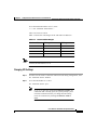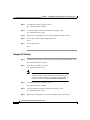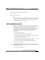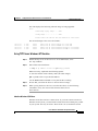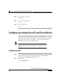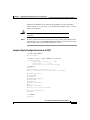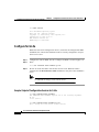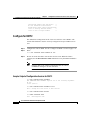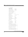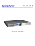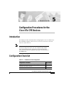
1
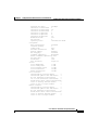
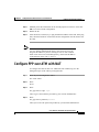
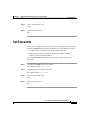
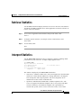
C H A P T E R
5
Configuration Procedures for the
Cisco 67x CPE Devices
Introduction
This chapter provides information about configuring the Cisco 67x CPE devices.
This information applies to the Cisco 673, Cisco 675, Cisco 675e, Cisco 676,
Cisco 677, and Cisco 678.
Note
Cisco recommends that only one command-line application at a time
be used to configure the Cisco 67x. For example, Telnet and the
serial management interface should not be used simultaneously.
Also, please note that all configuration procedures are performed in
the enable mode.
Configuration Checklist
Table 5-1
Checklist for Router Configuration
Configuration Procedures
Page Number
Log On to the Cisco Broadband Operating System
5-3
Determine the CBOS Version
5-3
Select a Connection Mode
5-5
Cisco 600 Series Installation and Operation Guide
78-11190-01
5-1
Chapter 5
Configuration Procedures for the Cisco 67x CPE Devices
Configuration Checklist
Table 5-1
Checklist for Router Configuration (continued)
Configuration Procedures
Page Number
Bridging Mode Procedures or Routing Mode Procedures
5-5 or 5-8
Configure the Ethernet Port (eth0)
5-10
Configure the WAN Ports and ATM Virtual Connections
5-11
Create Routing Tables
5-16
Enable IP Filtering
5-17
Configure Applications:
5-17
•
DHCP Client
5-18
•
DHCP Server
5-19
•
NAT
5-19
•
RADIUS Client
5-20
•
SNMP
5-22
•
SYSLOG Client
5-22
•
Telnet
5-24
•
TFTP Server
5-27
•
Web Server
5-30
Configure Timeout Values (Cisco 675, Cisco 678 in CAP
mode only)
5-30
Configure Line Coding (Cisco 677 and Cisco 678 only)
5-31
Upgrade Software through Serial Download
5-42
Configure Static NAT
5-43
Configure Multiple PCs Connected to the CPE
5-44
Update the CBOS Prompt
5-46
Set Passwords
5-47
Save Configuration Changes
5-48
Evaluate System Activity and Performance
5-48
Retrieve Statistics
5-49
Cisco 600 Series Installation and Operation Guide
5-2
78-11190-01
Chapter 5
Configuration Procedures for the Cisco 67x CPE Devices
Log On to the Cisco Broadband Operating System
Log On to the Cisco Broadband Operating System
After connecting all the cables to the Cisco 67x and powering it on, start the
terminal emulation program and press the Enter key until the CBOS login screen
appears. When you see the welcome screen, you can log on to CBOS.
Hello!
Expanding CBOS image...
CBOS v2.3.5.012 - Release Software
Password:
Note
If you have not set any passwords for the Cisco 67x, press the Enter
key when the system prompts you for a password to enter CBOS.
Determine the CBOS Version
After you log on to CBOS, you can use the show version command to determine
the CBOS version of the Cisco 67x:
cbos# show version
The output for Cisco 67x configured for CAP line coding is similar to the
following:
Cisco Broadband Operating System
CBOS (tm) 678 Software (C678-I-M), Version v2.3.5.012 - Release
Software
Copyright (c) 1986-1999 by cisco Systems, Inc.
Compiled Jan 10 2000 03:54:07
CAP firmware version C.19
NVRAM image at 0x10357fe0
Cisco 600 Series Installation and Operation Guide
78-11190-01
5-3
Chapter 5
Configuration Procedures for the Cisco 67x CPE Devices
Log On to the Cisco Broadband Operating System
The output for Cisco 678 configured for DMT Issue 2, G.Lite line coding is
similar to the following:
Cisco Broadband Operating System
CBOS (tm) 678 Software (C678-I-M), Version v2.3.5.012 - Release
Software
Copyright (c) 1986-1999 by cisco Systems, Inc.
Compiled Jan 5 2000 00:07:36
DMT firmware version 210
NVRAM image at 0x1034d930
*** RFC1483 Bridging Mode Enabled ***
Note
The show version command above displays the line coding method,
either CAP or DMT, for which the Cisco 67x is configured. If you
have a Cisco 677 or Cisco 678 and need to upgrade to a different line
coding method, follow the procedure in the “Configure Line Coding
(Cisco 677 and Cisco 678 only)” section on page 5-31 before
proceeding with configuration.
Operation Modes
The CBOS implements two operational modes: exec and enable. CBOS defaults
to exec mode when you log in. The exec mode grants program execution
(read-only) privileges to a user. To read or write changes to nonvolatile
random-access memory (NVRAM), you must work in enable mode. To invoke
enable mode:
Step 1
Type enable at the exec mode command line:
cbos> enable
Step 2
Enter a password when CBOS prompts you:
cbos> enable
Password:password
Cisco 600 Series Installation and Operation Guide
5-4
78-11190-01
Chapter 5
Configuration Procedures for the Cisco 67x CPE Devices
Select a Connection Mode
Note
If you have not set any passwords for the Cisco 67x, press the Enter
key when the system prompts you for a password to enter CBOS. If
you have not preset a password, you can still log on to the CBOS.
You must have an exec password set in order to Telnet into the
Cisco 67x.
You are now in enable mode. The system prompt appears:
cbos#
Select a Connection Mode
The CBOS supports two kinds of connection modes: bridging and routing.
Routing mode has two options: PPP routing (default) and RFC 1483 routing.
Note
Routing and bridging cannot be used simultaneously.
Bridging Mode Procedures
When the Cisco 67x operates in bridge mode, it behaves like a wire connecting a
local PC directly to a service provider’s network. Bridge data is encapsulated
using the RFC 1483 or PPP (BCP) protocol to enable data transport. Because
bridges operate at the Media Access Control (MAC) layer only, applications
requiring IP communication, such as Telnet, TFTP, RADIUS, Syslog, Ping, and
the web interface, are not available unless a management VC is configured.
Cisco currently supports a learning bridge mode. The virtual path
identifier/virtual channel identifier (VPI/VCI) configuration of the Cisco 67x is
unaffected by the operational mode (bridging versus routing) of the device.
Cisco also provides two methods of configuring and managing the bridged
Cisco 67x, through in-band bridging management or through a separate
management VC. The two methods cannot be used simultaneously. If a separate
management VC is used, the Cisco 67x can only be managed remotely through
wan0-1 and not from the local network.
Cisco 600 Series Installation and Operation Guide
78-11190-01
5-5
Chapter 5
Configuration Procedures for the Cisco 67x CPE Devices
Bridging Mode Procedures
With RFC 1483 management enabled, you can manage the router using Telnet.
The following commands are accessible through the managed bridge:
•
ping
•
telnet
•
tftp
The following procedure shows how to set up the Cisco 67x for in-band bridging
management.
Note
Step 1
You must be in enable mode and perform the procedure in the
sequence shown.
To enable RFC 1483 bridging, enter:
set bridging rfc1483 enabled
Step 2
To save your changes, enter:
write
Step 3
To reboot the device, enter:
reboot
Step 4
To enable in-band management of the bridge, enter:
set bridging management enabled
set int eth0 address ip address
The IP address of the Ethernet port should be an IP address on the same network
as that of the “far-end” station.
Step 5
To save your changes, enter:
write
Step 6
To enable your changes, reboot the router:
reboot
Cisco 600 Series Installation and Operation Guide
5-6
78-11190-01
Chapter 5
Configuration Procedures for the Cisco 67x CPE Devices
Bridging Mode Procedures
To manage the bridged Cisco 67x using a separate management VC:
Step 1
To disable in-band bridging management, enter:
set bridging management disabled
Step 2
To enable bridging PVC, enter:
set bridging PVC enabled
Step 3
To save your changes, enter:
write
Step 4
To reboot the device, enter:
reboot
After rebooting, the Cisco 67x will have two PVCs enabled. Wan0-0 is used
strictly for bridged traffic, while wan0-1 is used strictly for management traffic.
Wan0-1 will be using RFC 1483 routing.
Step 5
Set an IP address on the Ethernet port that is on the same network as the far-end
station out the wan0-1 interface:
set int eth0 address ip address
For more information on using the set bridging command, see the Cisco
Broadband Operating System User Guide.
The rules that govern the bridge command are:
•
Bridging and routing do not operate simultaneously on the Cisco 67x ADSL
router.
•
Only one bridging mode is allowed at any one time (that is, RFC 1483 or
PPP/BCP, not both).
•
The following commands do not work while in bridge mode:
– set route (and setting static routes)
– RIP-related commands (set and show)
– Filter-related commands (set and show)
– Web interface (only allowed if management is enabled)
Cisco 600 Series Installation and Operation Guide
78-11190-01
5-7
Chapter 5
Configuration Procedures for the Cisco 67x CPE Devices
Routing Mode Procedures
– RADIUS
– Syslog
– NAT
If you choose bridging as your connection mode, see also the following sections:
•
“Configure the WAN Ports and ATM Virtual Connections” section on
page 5-11
•
“Configure Applications” section on page 5-17 through “Evaluate System
Activity and Performance” section on page 5-48
Routing Mode Procedures
The Cisco 67x CPEs support two types of routing: PPP routing and RFC 1483
routing.
PPP Routing
Three Cisco 67x applications compose the PPP routing feature: DHCP server, and
Network Address Translation (NAT). With these applications enabled, you can
use the Cisco 67x without following the procedures described in this chapter such
as the “Bridging Mode Procedures” section on page 5-5 or the “Configure the
WAN Ports and ATM Virtual Connections” section on page 5-11. See the
following section to enable PPP routing.
Enabling PPP Routing
For each of the applications, the show application command reports if the feature
is enabled. Complete the following steps to enable the PPP routing feature for the
Cisco 67x. You must be in the enable mode to do this procedure.
Step 1
Enable the DHCP server:
set dhcp server enabled
Cisco 600 Series Installation and Operation Guide
5-8
78-11190-01
Chapter 5
Configuration Procedures for the Cisco 67x CPE Devices
Routing Mode Procedures
Step 2
To check whether this feature is enabled, enter:
show dhcp server pool 0
Step 3
Enable NAT:
set nat enabled
Step 4
Reboot the Cisco 67x:
reboot
Step 5
To check whether NAT is enabled, enter:
show nat
Step 6
Write the changes to NVRAM:
write
Step 7
Reboot the Cisco 67x:
reboot
When the Cisco 67x reboots, PPP routing is enabled.
Disabling PPP Routing
Complete the following steps to disable the PPP routing feature for the Cisco 67x.
You must be in the enable mode.
Step 1
Disable the DHCP server:
set dhcp server disabled
Step 2
Disable NAT:
set nat disabled
Step 3
Write the changes to NVRAM:
write
Cisco 600 Series Installation and Operation Guide
78-11190-01
5-9
Chapter 5
Configuration Procedures for the Cisco 67x CPE Devices
Routing Mode Procedures
Step 4
Reboot the Cisco 67x:
reboot
Note
After you disable the PPP routing feature, you must manually
configure the Cisco 67x.
Changing PPP Routing
These commands change the components of PPP routing:
•
set dhcp server pool
•
set dhcp client -interface
•
set nat entry add
•
set nat entry delete
•
set nat timeout
•
set nat outside -ip
For a complete description of each of these commands, see the Cisco Broadband
Operating System User Guide.
RFC 1483 Routing
If you disable PPP routing, see the following steps for RFC 1483 routing: from
the “Configure the Ethernet Port (eth0)” section on page 5-10 through the
“Evaluate System Activity and Performance” section on page 5-48.
Cisco 600 Series Installation and Operation Guide
5-10
78-11190-01
Chapter 5
Configuration Procedures for the Cisco 67x CPE Devices
Configure the Ethernet Port (eth0)
Configure the Ethernet Port (eth0)
To configure the Ethernet port, you must assign an IP address and netmask to the
port. Complete the following steps to configure your IP address and your netmask.
When setting the IP address of a particular interface, the netmask is set
automatically unless it is explicitly specified. Substitute your own IP addresses
for the ones shown in steps 2 through 4.
You must be in the enabled mode to do this procedure:
Step 1
Log on to the CBOS (cbos#) using the serial connection.
Note
Step 2
When changing the Cisco 67x IP configuration, use the
serial management connection to ensure you maintain your
session connection to CBOS.
To set the IP address (and your netmask), follow this example of a sample
command:
set interface eth0 address 192.168.34.9
The IP address becomes 192.168.34.9 and the netmask becomes 255.255.255.0 by
default. If you wish to explicitly set the netmask, enter:
set interface eth0 mask 255.255.255.248
Step 3
To set the destination IP address for the WAN port, enter:
set interface wan0-0 dest 192.168.34.10
Step 4
To save your changes, enter:
write
Step 5
To allow the system to come up with these new settings, reboot the Cisco 67x:
reboot
Step 6
Log back on to the CBOS to continue.
For more detailed information on the set interface command, see the Cisco
Broadband Operating System User Guide.
Cisco 600 Series Installation and Operation Guide
78-11190-01
5-11
Chapter 5
Configuration Procedures for the Cisco 67x CPE Devices
Configure the WAN Ports and ATM Virtual Connections
Configure the WAN Ports and ATM Virtual
Connections
The Cisco 67x has two types of WAN ports: physical (wan0) and logical
(wan0-x). The physical WAN port connects the Cisco 67x to the wide area
network. The logical WAN port or ports allow you to create virtual WAN
connections for plural destinations. To configure logical WAN ports, you must
provision ATM virtual connections. The instructions for each are provided in this
section.
The Cisco 67x automatically trains up to the ideal line speed. By default, the
Cisco 67x is provisioned with the following rates:
Encoding
Downstream/Upstream Rate (Mbps)
DMT
8.032/.864
CAP
7.168/1.088
G.Lite
1.536/.512
The maximum operative rate is determined by the central office ADSL equipment,
line length and line conditions.
On the Cisco 67x, the WAN0 port is always ready to send and receive network
traffic.You need to define an ATM virtual connection (VC), which might differ
from the default, when communicating across an ATM network. There are two
types of ATM connections:
•
Virtual paths, identified by virtual path identifiers (VPI)
•
Virtual circuit, identified by the combination of a VPI and a virtual circuit
identifier (VCI).
Because the Cisco 67x connects to the Cisco 6xxx series, the subscriber side
VPI/VCI settings are not seen by the ATM network. All subscriber side VCs use
VPI 1 and VCI 1 by default.
Cisco 67x comes preconfigured with one VC already established. Each VC is
expressed as WAN0-x, where x is a number between 0 and 3.
Cisco 600 Series Installation and Operation Guide
5-12
78-11190-01
Chapter 5
Configuration Procedures for the Cisco 67x CPE Devices
Configure the WAN Ports and ATM Virtual Connections
To set the maximum number of VCs, enter:
cbos# set interface wan0 maxvcs n
where n is between 1 and 8.
Table 5-2 shows the valid ranges for the VPI and VCI addresses.
Table 5-2
Note
VPI/VCI Address Ranges
Maximum VCs
VPI Range
VCI Range
1
0-3
0-63
2
0-3
0-63
4
0-3
0-63
8
0-3
0-63
In CBOS version 2.3 or earlier, the VPI count is 1 to 4. In later
versions, the VPI count is 1 to 8.
Changing VPI Settings
Step 1
To make sure the wan0-0 connection remains closed during configuration, enter:
set interface wan0-0 disable
Step 2
To set the VPI number to 2, enter:
set interface wan0-0 vpi 2
Note
If you try to enter the command set interface wan0-1 on a
connection that is already open, the system prompts you to
close that connection before you change the VPI setting.
Close the connection by entering set interface wan0-1
close.
Cisco 600 Series Installation and Operation Guide
78-11190-01
5-13
Chapter 5
Configuration Procedures for the Cisco 67x CPE Devices
Configure the WAN Ports and ATM Virtual Connections
Step 3
To enable the wan0-0 connection, enter:
set interface wan0-0 enable
Step 4
To begin using this connection with the new settings, enter:
set interface wan0-0 open
Step 5
Repeat steps 2 through 4 for every VPI assignment you want to make.
Step 6
To save the new WAN port configuration, enter:
write
Step 7
To exit CBOS, enter:
quit
Changing VCI Settings
Step 1
To make sure the wan0-0 connection remains closed during configuration, enter:
set interface wan0-0 disable
Step 2
To set the VCI number to 4, enter:
set interface wan0-0 vci 4
Note
Step 3
If you try to enter the command set interface wan0-0 on a
connection that is already open, the system prompts you to
close that connection before you change the VCI setting. To
do this, enter the command set interface wan0-0 close.
To enable the wan0-0 connection, enter:
set interface wan0-0 enable
Step 4
To begin using this connection with the new settings, enter:
set interface wan0-0 open
Step 5
Repeat steps 2 through 4 for every VCI assignment you want to make.
Cisco 600 Series Installation and Operation Guide
5-14
78-11190-01
Chapter 5
Configuration Procedures for the Cisco 67x CPE Devices
Set ScalaRate for wan0-x
Step 6
To save the new WAN port configuration, enter:
write
Step 7
To exit CBOS, enter:
quit
For more information on configuring VPI/VCI address mapping, see the Cisco
Broadband Operating System User Guide.
Set ScalaRate for wan0-x
ScalaRate is a technology developed by Cisco that allows dynamic allocation of
bandwidth within an ATM-based ADSL connection. This bandwidth allocation is
specified and controlled by the end-point devices without affecting the
provisioning or status of the underlying ATM transport VC. Bandwidth within the
ADSL connection is allocated on a VC basis and provides flexibility in rate
structures and deployment models for service providers and network
administrators.
The key features of ScalaRate are:
•
Applicable to individual logical WAN ports (wan0-x).
•
Sets maximum upstream rate per VC in the CPE, and maximum downstream
rate per subscriber in the central office equipment.
•
Can be set in increments of 64 Kbps.
•
Rounds down to the nearest 64 Kbps increment. For example, if you set the
rate to 68 Kbps, the setting will be rounded down to 64 Kbps.
•
Can be set for less than or equal to the maximum ADSL trained rate.
To set the wan0-x to ScalaRate:
Step 1
To close the wan0-x port, enter:
set interface wan0-x close
where x is the port you want to close.
Cisco 600 Series Installation and Operation Guide
78-11190-01
5-15
Chapter 5
Configuration Procedures for the Cisco 67x CPE Devices
Create Routing Tables
Step 2
To set an upstream ScalaRate for a particular VC, enter:
cbos# set interface wan0-0 rate 512
Step 3
To set an upstream ScalaRate to the maximum allowable rate, enter:
cbos# set interface wan0-0 rate auto
Step 4
To save your changes, enter:
cbos# write
Step 5
To exit the CBOS, enter:
cbos# quit
Create Routing Tables
In order to pass data through a network and onto the Internet or wide area
network, you might need to add the IP address(es) of gateway(s) to the routing
table. Follow the instructions below to build a routing table manually by adding
or deleting entries in the table.
Note
Step 1
If your Cisco 67x was provisioned to run in bridging or PPP routing
mode, you must disable both before attempting to establish routing.
To add a route and gateway to IP address 192.168.9.1, without specifying a
specific mask or metric, enter:
set route add ip 192.168.9.1 gw 192.168.10.250
Step 2
To add a route and specify a netmask, gateway, or metric, enter:
set route add ip 192.168.10.0 mask 255.255.255.0
gw 192.168.245.228 metric 1
Step 3
To set a default route, enter:
set route default 192.168.245.228
Cisco 600 Series Installation and Operation Guide
5-16
78-11190-01
Chapter 5
Configuration Procedures for the Cisco 67x CPE Devices
Enable IP Filtering
Step 4
To set a destination address for each VC, enter:
set interface wan0-0 dest 192.168.245.228
mask 255.255.255.0
Step 5
To save your changes, enter:
write
Step 6
To exit the CBOS, enter:
quit
For more information on using the set route command, see the Cisco Broadband
Operating System User Guide.
Enable Routing Information Protocol (RIP)
To enable RIP and RIP2 in CBOS, enter:
set rip enabled
To disable RIP, enter:
set rip disabled
For more information on using the set rip commands, see the Cisco Broadband
Operating System User Guide.
Enable IP Filtering
The Cisco 67x supports up to 20 filters for TCP and UDP packets passing through
the Cisco 67x’s interfaces. Enabled filters are applied to packets in sequential
order according to filter number.
To use filtering to block all packets going through the Ethernet interface, enter:
set filter 0 on deny eth0 0.0.0.0 0.0.0.0 0.0.0.0 0.0.0.0
For more information on using the set filter command, see the Cisco Broadband
Operating System User Guide.
Cisco 600 Series Installation and Operation Guide
78-11190-01
5-17
Chapter 5
Configuration Procedures for the Cisco 67x CPE Devices
Configure Applications
Configure Applications
The Cisco 67x supports these applications for system management and control:
•
DHCP client
•
DHCP server
•
NAT
•
RADIUS client
•
SNMP
•
SYSLOG client
•
Telnet server
•
TFTP server
•
Web server (HTTP server)
DHCP Client
The DHCP client requests an IP address from a DHCP server. To enable the
DHCP client:
Note
Step 1
Enabling the DHCP client automatically disables the DHCP server
on the CPE.
Enable the DHCP client:
set dhcp client enabled
Step 2
To change the DHCP client interface, enter:
set dhcp client interface eth0
Step 3
To check whether this feature is enabled, enter:
show dhcp client
Step 4
Write the changes to NVRAM:
write
Cisco 600 Series Installation and Operation Guide
5-18
78-11190-01
Chapter 5
Configuration Procedures for the Cisco 67x CPE Devices
Configure Applications
Step 5
Reboot the Cisco 67x:
reboot
For more information on using DHCP clients, see the set dhcp client commands
in the Cisco Broadband Operating System User Guide.
DHCP Server
The DHCP server application automatically assigns IP addresses to DHCP
clients. To enable the DHCP server feature for the Cisco 67x.
Note
Step 1
Enabling the DHCP server automatically disables the DHCP client
on the CPE.
Enable the DHCP server:
set dhcp server enabled
Step 2
To check whether this feature is enabled, enter:
show dhcp server
Step 3
Write the changes to NVRAM:
write
Step 4
Reboot the Cisco 67x:
reboot
Note
The DHCP server defaults with one IP address poolcconfigured.
For more information on using DHCP servers, see the set dhcp server series of
commands in Cisco Broadband Operating System User Guide.
Cisco 600 Series Installation and Operation Guide
78-11190-01
5-19
Chapter 5
Configuration Procedures for the Cisco 67x CPE Devices
Configure Applications
NAT
The NAT application converts IP addresses on a private network (designated as
“inside” or “LAN”) to global IP addresses that can forward packets to another
registered network (designated as “outside” or “WAN”). To enable NAT:
Step 1
Enable NAT:
set nat enabled
Step 2
To check whether this feature is enabled, enter:
show nat
Step 3
Write the changes to NVRAM:
write
Step 4
Reboot the Cisco 67x:
reboot
For more information on using NAT, see the set nat series of commands in Cisco
Broadband Operating System User Guide.
RADIUS Client
RADIUS authenticates users for access to a network. The RADIUS server uses an
authentication scheme, such as PAP, to authenticate incoming messages from
RADIUS clients. When a password is present, it is hidden using a method based
on the RSA Message Digest Algorithm MD5 [1].
The Cisco 67x has been successfully tested for compatibility with the following
RADIUS server providers:
•
Livingston Enterprises RADIUS 2.01
•
Merit RADIUS (Sun binary)
•
RADIUS NT (Microsoft)
Cisco 600 Series Installation and Operation Guide
5-20
78-11190-01
Chapter 5
Configuration Procedures for the Cisco 67x CPE Devices
Configure Applications
•
CiscoSecure for UNIX
•
CiscoSecure for Windows NT
Cisco 67x Implementation
The Cisco 67x supports a RADIUS client. However, for most environments, the
Cisco 67x RADIUS client is not used. The RADIUS profile exists on the service
provider’s remote access server.
Configuring RADIUS on the Cisco 67x
The following examples assume that the Cisco 67x is connected to a network
equipped with a RADIUS server:
Note
Step 1
If you enable RADIUS on the CPE, you have to disable
authentication on the service provider’s remote access server.
Enable the Cisco 67x RADIUS application:
set radius enabled
RADIUS is enabled
Step 2
Point the CPE to the remote RADIUS server:
set radius remote x.x.x.x
RADIUS will now send messages to x.x.x.x
where x.x.x.x is the address of the remote RADIUS server.
Step 3
Set the RADIUS secret password:
set radius secret mysecret
RADIUS Secret now set - All secrets are in lowercase
where mysecret is the RADIUS secret password.
Step 4
Enable RADIUS authentication and set the PPP login and password for the
WAN0-0 port:
set ppp wan0-0 radius enabled
set ppp wan0-0 login cisco
set ppp wan0-0 password is_great
Cisco 600 Series Installation and Operation Guide
78-11190-01
5-21
Chapter 5
Configuration Procedures for the Cisco 67x CPE Devices
Configure Applications
where cisco is the PPP login and is_great is the password.
Step 5
Use the show radius command to display the Cisco 67x default configuration for
RADIUS.
Note
The RADIUS test command set radius test activates the
RADIUS debug option. This allows you to test that RADIUS
works with current client settings by sending a test message
to the RADIUS server.
For more information on RADIUS commands, see the Cisco Broadband
Operating System User Guide.
SNMP
To configure SNMP settings, enter the following command from enable mode:
set snmp enabled | disabled | remote
remote-address
| traps
host-address
where
disabled
Disables SNMP settings
enabled
Enables SNMP settings
remote remote-address
Specifies the IP address for the remote
location running SNMP
traps host-address
Sets the IP address of the host on which
to trap SNMP messages
The following example command uses hypothetical IP addresses to demonstrate
the use of the set snmp command:
set snmp remote 198.162.2.57
set snmp traps 198.162.2.50
Cisco 600 Series Installation and Operation Guide
5-22
78-11190-01
Chapter 5
Configuration Procedures for the Cisco 67x CPE Devices
Configure Applications
SYSLOG Client
SYSLOG logs significant system information to a remote SYSLOG server for
processing without requiring large amounts of local storage or local processing.
Implementing SYSLOG
Using the CBOS, the Cisco 67x allows you to specify a remote server for logging
system messages. Cisco supports the following levels of severity:
•
Debug
•
Info
•
Warning
•
Alarm
•
Critical
•
Crash
The messages are similar to the standard Berkley Software Distribution
(BSD)-style severity levels for SYSLOG; however, they do not include None and
Mark. To configure your SYSLOG daemon to receive Cisco SYSLOG messages,
modify the /etc/syslog.conf configuration file (remember to use tabs, not
spaces). Many systems, such as Linux and FreeBSD, have SYSLOG set up by
default.
Note
The command set syslog test activates the SYSLOG debug option.
This will verify that SYSLOG works with current client settings by
sending a test message to the SYSLOG server.
The following /etc/syslog.conf configuration file entry enables all messages for
Info severity levels and above:
*.info/var/log/messages
To enable only alarm messages and above, enter the following in /etc/syslog.conf:
*.alarm/var/log/messages
Cisco 600 Series Installation and Operation Guide
78-11190-01
5-23
Chapter 5
Configuration Procedures for the Cisco 67x CPE Devices
Configure Applications
Be sure your UNIX syslogd daemon accepts remote reception (network
messages). Some processes might need to be killed and restarted with a -r option.
Using the man syslog command to view the online UNIX manuals for
information about the SYSLOG daemon.
Using SYSLOG from a UNIX Machine
To use SYSLOG, simply enter the following at your CBOS prompt:
set syslog remote ip address of remote server
Attention Windows NT and Windows 95/98 Users
Windows does not have a SYSLOG server. If you want to utilize SYSLOG on a
Windows 95, Windows 98, or Windows NT system, you must install a SYSLOG
server from a third-party vendor onto your system. One way to locate a SYSLOG
server is to use an Internet search engine to locate a vendor who sells a SYSLOG
server. Some SYSLOG servers are provided as share or freeware on the Internet.
Cisco has proven compatibility with the following third-party products:
•
Sun Solaris 2.5
•
Linux 2.0.27
•
NTSyslog (shareware program)
For more information on SYSLOG commands, see the Cisco Broadband
Operating System User Guide.
Telnet
Telnet provides a command-line interface and is used as a means of providing
remote login connections between machines on many networks, including the
Internet.
Caution
Before closing a Telnet connection, always enter exit or quit at the
cbos# prompt.
Cisco 600 Series Installation and Operation Guide
5-24
78-11190-01
Chapter 5
Configuration Procedures for the Cisco 67x CPE Devices
Configure Applications
Using Telnet to Connect to the Cisco 67x
Use the telnet daemon to connect to CBOS and configure and operate the
Cisco 67x.
Note
You must have an exec password set to make a Telnet connection to
the Cisco 67x.
Connecting from a Windows NT 4.0 or Windows 95/98 Machine
Step 1
Click Start.
Step 2
Select the Run... option.
Step 3
When the Run box appears, enter telnet in the space provided.
Step 4
Click OK. The Connect menu appears.
Step 5
Select the Remote System... option from the Connect menu. The screen shown in
Figure 5-1 appears.
Figure 5-1
Remote System List Box
Step 6
Enter the IP address of the Cisco 67x in the Host Name box and click Connect.
The system then initiates a session with the Cisco 67x. Press the Enter key three
or four times to establish a connection.
Step 7
Provide the exec user password information. After the system authenticates your
password, you have access to CBOS.
Cisco 600 Series Installation and Operation Guide
78-11190-01
5-25
Chapter 5
Configuration Procedures for the Cisco 67x CPE Devices
Configure Applications
Note
See the Cisco Broadband Operating System User Guide for more
information about how to set and change passwords.
Notice to Windows Users
The Windows Telnet client does not support NVT (Network Virtual Terminal) or
any extra form of option negotiation. However, if you are going to use the
Windows Telnet client, follow these steps to set your terminal settings.
Step 1
When the Telnet window appears, access the Preferences menu in Telnet by
selecting Preferences from the Terminal drop-down menu. (See Figure 5-2.)
Figure 5-2
Step 2
Telnet Preferences
Set the terminal settings on the Terminal Preferences menu to the values shown in
Figure 5-3, then click OK.
Figure 5-3
Telnet Preferences
Notice to Linux Users
If you try to run Linux without installing the Term/Termcap database, the message
BAD ADDRESS displays during a connection attempt. To install the
Term/Termcap database, check the original Linux installation disks.
Cisco 600 Series Installation and Operation Guide
5-26
78-11190-01
Chapter 5
Configuration Procedures for the Cisco 67x CPE Devices
Configure Applications
Connecting from a UNIX Machine
Step 1
Enter the following at your prompt:
telnet ip address of Cisco 67x
After you have connected to the Cisco 67x, the following information appears on
your terminal:
Password: password
Step 2
Provide the exec user password. After the system authenticates the password, you
have access to the CBOS.
How to Keep Telnet from Timing Out During Your Session
Telnet sessions time out after a period of inactivity. Enter the following
commands to keep the Telnet client from timing out.
set telnet timeout off
write
For more information on Telnet commands, see the Cisco Broadband Operating
System User Guide.
TFTP Server
TFTP allows you to transfer files to and from a Cisco 67x. The Cisco 67x runs a
tftp daemon, which allows users from remote machines who have TFTP client
software to remotely transfer files to and from the Cisco 67x. The TFTP client can
be enabled and disabled from the CBOS or the Web Management Interface.
Caution
For security reasons, Cisco recommends that you disable the TFTP
application, except when uploading or downloading a file.
Cisco 600 Series Installation and Operation Guide
78-11190-01
5-27
Chapter 5
Configuration Procedures for the Cisco 67x CPE Devices
Configure Applications
Software Updates
Use TFTP to transfer a new software image from Cisco to your Cisco 67x, where
the file name format is: nsrouter.c67ydmt.x.x.x.x.bin or c67ydmt.x.x.x.x.bin. The
x.x.x represents the image version number, and 67y is your CPE model number,
for example, 677.
Note
If you are upgrading from CBOS 2.2, you must use the
nsrouter.c67ydmt.x.x.x.x.bin filename format. If you are upgrading
from CBOS 2.3, you can use either format.
Archives
Use TFTP to back up a copy of your configuration file before changing it, so you
can easily recover the old file when necessary. The naming conventions for the
configuration file are:
•
When using the put option of the tftp command, you must name the file
nscfg.cfg.
•
When using the get option of the tftp command, name the file any name that
a standard text editor can view and edit.
Using TFTP from a UNIX Machine
For information on the UNIX TFTP client, access the online manual by entering:
man tftp
The manual page for TFTP appears.
To upgrade the Cisco 67x image:
root@staten-</67x>tftp
tftp> mode binary
tftp> put 12.0.8.5:nsrouter.c67xdmt.2.3.5.012.bin
Sent 923574 bytes in 60.8 seconds
Cisco 600 Series Installation and Operation Guide
5-28
78-11190-01
Chapter 5
Configuration Procedures for the Cisco 67x CPE Devices
Configure Applications
The CPE displays the following when the image is being upgraded:
cbos>
Downloading legacy image..... done.
Saving image................. done.
Please reboot the CPE for the new download to take effect
The released images come in two file formats:
-rw-r--r--rw-r--r--rw-r--r--rw-r--r--
1
1
1
1
root
root
root
root
other
other
other
other
924976
922336
924870
922230
Jan
Jan
Jan
Jan
31
31
31
31
09:04
09:04
09:04
09:04
c678cap.2.3.5.012.bin
c678dmt.2.3.5.012.bin
nsrouter.c678cap.2.3.5.012.bin
nsrouter.c678dmt.2.3.5.012.bin
Using TFTP from a Windows NT Machine
Step 1
Enable the tftp server on the Cisco 67x. As an enabled user, enter:
set tftp enabled
Step 2
Start a DOS session and enter:
C:>tftp -i ip address of Cisco 67x put image_filename
Where necessary, implement the following options:
-i—Sets the transfer mode to binary mode (all router images)
put—Uploads a file to a specified IP address
Use the show errors command to verify that TFTP is working.
Step 3
Be sure that you reboot the device to activate the new image.
Step 4
When you log back in to the Cisco 67x after the reboot, use the following
command to verify the version of the firmware that is active:
show version
Attention Windows 95/98 Users
Windows 95/98 does not have a TFTP client. If you want to utilize TFTP on a
Windows 95/98 system, you must install a TFTP client from a third-party vendor
on your system. One way to locate a TFTP client is to use an Internet search
Cisco 600 Series Installation and Operation Guide
78-11190-01
5-29
Chapter 5
Configure Timeout Values (Cisco 675, Cisco 678 in CAP mode only)
Configuration Procedures for the Cisco 67x CPE Devices
engine to locate a vendor who sells a TFTP client. Some TFTP clients are
provided as shareware or freeware on the Internet. Cisco will provide a TFTP
client upon request. TFTP client requests should be directed to the Technical
Assistance Center.
For more information on TFTP commands, see the Cisco Broadband Operating
System User Guide.
Web Server
The Cisco 67x supports a web server, which allows you to perform tasks such as
configuring interfaces, displaying statistics, and much more. For a complete
description of the web interface, see the Cisco Broadband Operating System User
Guide.
Configure Timeout Values (Cisco 675, Cisco 678 in
CAP mode only)
The Cisco 67x supports two timeout values: session and idle. The session timeout
is based on the total uptime of the session. The setting of the idle timeout
facilitates the release of the ADSL physical layer so that the central office
resource can be released, based on inactivity. The expiration of either timeout will
end the ADSL session. However, because authentication is invisible, only the
training delay is perceived by the user (7 to 46 seconds) when the connection is
reestablished.
Use the set timeout command in a DOH environment to configure the idle or
session timeout values in seconds.
Step 1
To set the session timeout rate to 300 seconds, enter:
set timeout session 300
Step 2
To set the idle timeout rate to 300 seconds, enter:
set timeout idle 300
Cisco 600 Series Installation and Operation Guide
5-30
78-11190-01
Chapter 5
Configuration Procedures for the Cisco 67x CPE Devices
Configure Line Coding (Cisco 677 and Cisco 678 only)
Step 3
To verify these values, enter:
show timeout
Step 4
To save your changes, enter:
write
Step 5
To exit CBOS, enter:
quit
Configure Line Coding (Cisco 677 and Cisco 678 only)
The Cisco 677 and Cisco 678 allow you to choose transmission protocols to match
your network configuration by changing the router’s configuration file. Use TFTP
to transfer files to and from a CPE. This section describes procedures to configure
the CPE for Discrete Multi-Tone (DMT), Carrierless Amplitude and Phase
Modulation (CAP), G.Lite, or G.DMT protocols.
Note
Changes to your CPE must be coordinated with the central office
equipment. Not all protocols described here are available on all CPE
models.
Configure for CAP
Step 1
Verify the connection from the router to the location where the correct software
image is stored. This location is provided by your network administrator.
Typically, you use the ping command for this step.
Step 2
Enable TFTP:
cbos#set tftp enabled
TFTP is enabled
Cisco 600 Series Installation and Operation Guide
78-11190-01
5-31
Chapter 5
Configuration Procedures for the Cisco 67x CPE Devices
Configure Line Coding (Cisco 677 and Cisco 678 only)
Step 3
Set the remote address for the TFTP host computer:
cbos # set tftp remote ip address
This command tells the CPE to accept TFTP transfers from a specific IP address.
An example remote IP address would be 192.168.35.4. This address is an example
only; do not use it to configure the router.
Note
If you do not have the CPE address, consult your network
administrator.
For more information about TFTP, see the “TFTP Server”
section on page 5-27.
Step 4
To start the file transfer from a PC, start a DOS session and enter the following
command:
C:>tftp –i CPE IP address put image_filename
Where necessary, implement the following values:
-i
Sets the transfer mode to binary mode
put
Uploads a file onto that IP address
To start the file transfer from a UNIX machine, enter:
root@staten-</678>tftp
tftp> mode binary
tftp> put CPE IP address:image_filename
Sent 922294 bytes in 54.9 seconds
Substitute the file name for the software image update. Files use the naming
format c67ycap.x.x.x.x.bin, where 67y is the CPE model number, and x.x.x.x is the
image version number.
Caution
Do not turn off the power to the router until after the file transfer is
completed.
Cisco 600 Series Installation and Operation Guide
5-32
78-11190-01
Chapter 5
Configuration Procedures for the Cisco 67x CPE Devices
Configure Line Coding (Cisco 677 and Cisco 678 only)
Step 5
Be sure to reboot the CPE to activate the new image. When you log back in to the
CPE after the reboot, use the show version command to verify the version of the
firmware that is active. Note the CAP firmware version.
Sample Output of Configuration Session for CAP
cbos#set tftp enabled
TFTP is enabled
cbos#tftp image 10.9.1.20 c678cap.2.3.5.012.bin
Starting download...
Downloading in progress...... done.
Saving image...........done.
Please reboot the CPE for the new downl
cbos#reboot
Hello!
C67x self-update code: Release 2.3
NOTE: Do not power off router until update is finished!
Decompressing router...
Erasing FLASH......
Programming...
Decompressing monitor...
Erasing FLASH.........
Programming...
Finished. Rebooting...
Hello!
Expanding CBOS image...
CBOS v2.3.5.012 - Release Software
User Access Verification
Password:
cbos>enable
Password:
cbos#show version
Cisco Broadband Operating System
CBOS (tm) 025 - Release Software
Copyright (c) 1986-1999 by cisco Systems, Inc.
Compiled Dec 21 1999 20:37:27
CAP firmware version C.19
NVRAM image at 0x10356930
Cisco 600 Series Installation and Operation Guide
78-11190-01
5-33
Chapter 5
Configuration Procedures for the Cisco 67x CPE Devices
Configure Line Coding (Cisco 677 and Cisco 678 only)
Configure for DMT
Step 1
Verify the connection from the router to the location where the correct software
image is stored. This location is provided by your network administrator.
Typically, you use the ping command for this step.
Step 2
Enable TFTP:
cbos#set tftp enabled
TFTP is enabled
Step 3
Set the remote address for the TFTP host computer:
cbos # tftp remote ip address
This command tells the CPE to accept TFTP transfers from a specific IP address.
An example remote IP address would be 192.168.35.4. This address is an example
only; do not use it to configure the router.
Note
If you do not have the CPE address, consult your network
administrator.
For more information about TFTP, see “TFTP Server”
section on page 5-27.
Step 4
To start the file transfer from a PC, start a DOS session and enter:
C:>tftp –i CPE IP address put image_filename
Where necessary, implement the following values:
-i
Sets the transfer mode to binary mode
put
Uploads a file onto that IP address
To start the file transfer from a UNIX machine, enter:
root@staten-</678>tftp
tftp> mode binary
tftp> put CPE IP address:image_filename
Sent 922294 bytes in 54.9 seconds
Cisco 600 Series Installation and Operation Guide
5-34
78-11190-01
Chapter 5
Configuration Procedures for the Cisco 67x CPE Devices
Configure Line Coding (Cisco 677 and Cisco 678 only)
Substitute the filename for the software image update. Files use the naming
format c67ydmt.x.x.x.x.bin where 67y is the CPE model number, and x.x.x.x is the
image version number.
Caution
Step 5
Do not turn off the power to the router until after the file transfer is
completed.
Be sure to reboot the CPE to activate the new image. When you log back in to the
CPE after the reboot, use the show version command to verify the version of the
firmware that is active. Note the DMT firmware version.
Sample Output of Configuration Session for DMT
cbos#set tftp enabled
TFTP is enabled
cbos#tftp -i 10.9.1.20 get c678dmt.2.3.5.012.bin
Starting download...
Downloading in progress...... done.
Saving image...........done.
Please reboot the CPE for the new downl
cbos#reboot
Hello!
C67x self-update code: Release 2.3.5.012
NOTE: Do not power off router until update is finished!
Decompressing router...
Erasing FLASH......
Programming...
Decompressing monitor...
Erasing FLASH.........
Programming...
Finished. Rebooting...
Hello!
Expanding CBOS image...
CBOS v2.3.5.012 - Release Software
User Access Verification
Password:
cbos>enable
Password:
Cisco 600 Series Installation and Operation Guide
78-11190-01
5-35
Chapter 5
Configuration Procedures for the Cisco 67x CPE Devices
Configure Line Coding (Cisco 677 and Cisco 678 only)
cbos#show version
Cisco Broadband Operating System
CBOS (tm) 025 - Release Software
Copyright (c) 1986-1999 by cisco Systems, Inc.
Compiled Dec 21 1999 20:37:27
DMT firmware version 210
NVRAM image at 0x10356930
Configure for G.Lite
Before the CPE can be configured for G.Lite, it must first be configured for DMT.
In addition, the central office hardware must be correctly configured to accept a
G.Lite service user.
Step 1
Configure the CPE for DMT. See the “Configure for DMT” section on page 5-33.
Step 2
Enter:
cbos# set interface wan0 standard g.lite
Step 3
Be sure to retrain the CPE to activate the new line code. When the CPE is
retrained, use the show interface wan0 command to verify the G.Lite standard is
active.
Note
Changes made to the running configuration must be written
to NVRAM for changes to be seen on reboot.
Sample Output of Configuration Session for G.Lite
cbos#set interface wan0 standard
SET INTERFACE WANx STANDARD requires one of the following arguments
T1.413
G.lite (G992.2)
cbos#set interface wan0 standard g.lite
Note: Change will take effect on next retrain.
Cisco 600 Series Installation and Operation Guide
5-36
78-11190-01
Chapter 5
Configuration Procedures for the Cisco 67x CPE Devices
Configure Line Coding (Cisco 677 and Cisco 678 only)
cbos#set interface wan0 retrain
cbos#show interface wan0
wan0
ADSL Physical Port
Line Trained
Actual Configuration:
Overhead Framing:
3
Trellis Coding:
Disabled
Standard Compliance:
G.lite
Downstream Data Rate:
1536 Kbps
Upstream Data Rate:
512 Kbps
Interleave S Downstream:
4
Interleave D Downstream:
16
Interleave R Downstream:
4
Interleave S Upstream:
8
Interleave D Upstream:
8
Interleave R Upstream:
8
Modem Microcode:
G96
DSP version:
0
Operating State:
Showtime/Data Mode
Configured:
Echo Cancellation:
Disabled
Overhead Framing:
3
Coding Gain:
Auto
TX Power Attenuation:
0dB
Trellis Coding:
Enabled
Bit Swapping:
Disabled
Standard Compliance:
G.lite
Remote Standard Compliance:T1.413
Tx Start Bin:
0x6
Tx End Bin:
0x1f
Data Interface:
Utopia L1
Status:
Local SNR Margin:
28.0dB
Local Coding Gain:
1.5dB
Local Transmit Power:
12.3dB
Local Attenuation:
22.5dB
Remote Attenuation:
21.5dB
Local Counters:
Interleaved RS Corrected Bytes:
0
Interleaved Symbols with CRC Errors:
0
No Cell Delineation Interleaved:
0
Out of Cell Delineation Interleaved:
0
Header Error Check Counter Interleaved:0
Count of Severely Errored Frames:
0
Count of Loss of Signal Frames:
0
Remote Counters:
Interleaved RS Corrected Bytes:
0
Cisco 600 Series Installation and Operation Guide
78-11190-01
5-37
Chapter 5
Configuration Procedures for the Cisco 67x CPE Devices
Configure Line Coding (Cisco 677 and Cisco 678 only)
Interleaved Symbols with CRC Errors:
0
No Cell Delineation Interleaved:
0
Header Error Check Counter Interleaved:0
Count of Severely Errored Frames:
0
Count of Loss of Signal Frames:
0
Configure for DMT2
The default line coding mode for the Cisco 677 and Cisco 678 is DMT2. The
central office hardware must be correctly configured to accept a DMT2 service
user.
Step 1
Configure the CPE for DMT. See the “Configure for DMT” section on page 5-33.
Step 2
Enter:
cbos# set interface wan0 standard t1.413
Step 3
Be sure to retrain the CPE to activate the new line code. When the CPE is
retrained, use the show interface wan0 command to verify the DMT2 standard is
active.
Note
Changes made to the running configuration must be written
NVRAM for changes to be seen on reboot.
Sample Output of Configuration Session for DMT2
cbos#set interface wan0 standard
SET INTERFACE WANx STANDARD requires one of the following arguments
T1.413
G.lite (G992.2)
cbos#set interface wan0 standard t1.413
Note: Change will take effect on next retrain.
cbos#set interface wan0 retrain
cbos#show interface wan0
wan0
ADSL Physical Port
Cisco 600 Series Installation and Operation Guide
5-38
78-11190-01
Chapter 5
Configuration Procedures for the Cisco 67x CPE Devices
Configure Line Coding (Cisco 677 and Cisco 678 only)
Line Trained
Actual Configuration:
Overhead Framing:
3
Trellis Coding:
Disabled
Standard Compliance:
T1.413
Downstream Data Rate:
8032 Kbps
Upstream Data Rate:
864 Kbps
Interleave S Downstream:
1
Interleave D Downstream:
64
Interleave R Downstream:
2
Interleave S Upstream:
4
Interleave D Upstream:
8
Interleave R Upstream:
16
Modem Microcode:
G96
DSP version:
0
Operating State:
Showtime/Data Mode
Configured:
Echo Cancellation:
Disabled
Overhead Framing:
3
Coding Gain:
Auto
TX Power Attenuation:
0dB
Trellis Coding:
Enabled
Bit Swapping:
Disabled
Standard Compliance:
Multimode
Remote Standard Compliance:T1.413
Tx Start Bin:
0x6
Tx End Bin:
0x1f
Data Interface:
Utopia L1
Status:
Local SNR Margin:
3.5dB
Local Coding Gain:
0.0dB
Local Transmit Power:
12.5dB
Local Attenuation:
28.5dB
Remote Attenuation:
18.5dB
Local Counters:
Interleaved RS Corrected Bytes:
0
Interleaved Symbols with CRC Errors:
2
No Cell Delineation Interleaved:
0
Out of Cell Delineation Interleaved:
0
Header Error Check Counter Interleaved:0
Count of Severely Errored Frames:
0
Count of Loss of Signal Frames:
0
Remote Counters:
Interleaved RS Corrected Bytes:
0
Interleaved Symbols with CRC Errors:
0
No Cell Delineation Interleaved:
0
Header Error Check Counter Interleaved:0
Count of Severely Errored Frames:
0
Cisco 600 Series Installation and Operation Guide
78-11190-01
5-39
Chapter 5
Configuration Procedures for the Cisco 67x CPE Devices
Configure Line Coding (Cisco 677 and Cisco 678 only)
Count of Loss of Signal Frames:
0
Configure for G.DMT
Before the CPE can be configured for G.DMT, the .full image must be loaded. See
the latest Release Notes for the Cisco Broadband Operating Sytsem for the
appropriate filenames to use. The central office hardware must be correctly
configured to accept a G.DMT service user.
Step 1
Enter the following command:
cbos# set interface wan0 standard g.992.1
Step 2
Be sure to retrain the CPE to activate the new line code. When the CPE is
retrained, use the show interface wan0 command to verify the G.DMT standard
is active. Note that the standard configuration for the .full image is DMT2.
Note
Changes made to the running configuration must be written
to NVRAM for changes to be seen on reboot.
Sample Output of Configuration Session for G.DMT
cbos#set interface wan0 standard
SET INTERFACE WANx STANDARD requires one of the following arguments
T1.413
G.dmt (G992.1)
cbos#set interface wan0 standard g.992.1
Note: Change will take effect on next retrain.
cbos#show interface wan0
wan0 ADSL Physical Port
Line Trained
Actual Configuration:
Overhead Framing:
Trellis Coding:
Standard Compliance:
Downstream Data Rate:
3
Disabled
g.992.1
8032 Kbps
Cisco 600 Series Installation and Operation Guide
5-40
78-11190-01
Chapter 5
Configuration Procedures for the Cisco 67x CPE Devices
Configure Line Coding (Cisco 677 and Cisco 678 only)
Upstream Data Rate:
864 Kbps
Interleave S Downstream:
1
Interleave D Downstream:
64
Interleave R Downstream:
2
Interleave S Upstream:
4
Interleave D Upstream:
8
Interleave R Upstream:
16
Modem Microcode:
G96
DSP version:
0
Operating State:
Showtime/Data Mode
Configured:
Echo Cancellation:
Disabled
Overhead Framing:
3
Coding Gain:
Auto
TX Power Attenuation:
0dB
Trellis Coding:
Enabled
Bit Swapping:
Disabled
Standard Compliance:
Multimode
Remote Standard Compliance:g.992.1
Tx Start Bin:
0x6
Tx End Bin:
0x1f
Data Interface:
Utopia L1
Status:
Local SNR Margin:
3.5dB
Local Coding Gain:
0.0dB
Local Transmit Power:
12.5dB
Local Attenuation:
28.5dB
Remote Attenuation:
18.5dB
Local Counters:
Interleaved RS Corrected Bytes:
0
Interleaved Symbols with CRC Errors:
2
No Cell Delineation Interleaved:
0
Out of Cell Delineation Interleaved:
0
Header Error Check Counter Interleaved:0
Count of Severely Errored Frames:
0
Count of Loss of Signal Frames:
0
Remote Counters:
Interleaved RS Corrected Bytes:
0
Interleaved Symbols with CRC Errors:
0
No Cell Delineation Interleaved:
0
Header Error Check Counter Interleaved:0
Count of Severely Errored Frames:
0
Count of Loss of Signal Frames:
0
Cisco 600 Series Installation and Operation Guide
78-11190-01
5-41
Chapter 5
Configuration Procedures for the Cisco 67x CPE Devices
Upgrade Software through Serial Download
Upgrade Software through Serial Download
You can upgrade software on your CPE using the serial interface:
Note
Changes to your CPE must be coordinated with the central office
equipment.
Step 1
Enter the following settings through a serial console connected to your system:
38.4 Kbaud
No parity
8 data bits
1 stop bit
No flow control
Step 2
To turn debug monitor on, enter:
debug monitor on
Step 3
To save your changes, enter:
write
Step 4
To reboot the device, enter:
reboot
After the CPE reboots, press Enter twice. The prompt should change to =>.
Step 5
To erase sector 0, enter:
es 0
Repeat this step for sectors 1 through 5.
Step 6
To start serial download, enter:
df 10008000
Step 7
Use a terminal emulation application, such as HyperTerminal, to start an Xmodem
download of a new Cisco 67x image.
Step 8
When the download is complete, the following message appears:
Transferred xxxxxxxx bytes
Record the number of bytes transferred.
Cisco 600 Series Installation and Operation Guide
5-42
78-11190-01
Chapter 5
Configuration Procedures for the Cisco 67x CPE Devices
Configure Static NAT
Step 9
To program the area of memory to Flash, enter:
pb 10008000 fef00000 xxxxxxxx
where xxxxxxxx is the value recorded in Step 6.
Step 10
To turn debug monitor off, enter:
m0
Step 11
To reboot, enter:
rb
Configure Static NAT
Prior to following these steps, contact your application vendor to find out which
ports they use.
Step 1
At the command prompt of the CPE, enter:
cbos#enable
Step 2
Enter:
set nat entry add inside-ip-addr inside-port outside-ip-addr
outside-port protocol
where protocol is UDP, TCP or ICMP. The default local CPE services ports are:
Service
Protocol Port
Telnet
TCP
23
TFTP
UDP
69
SNMP
UDP
161
Web Server
TCP
80
Cisco 600 Series Installation and Operation Guide
78-11190-01
5-43
Chapter 5
Configuration Procedures for the Cisco 67x CPE Devices
Configure Multiple PCs Connected to the CPE
For example, if the private address of your server is 10.0.0.2 and the public/routed
address assigned to your CPE is 216.160.92.4 and you are running a web server,
enter:
set nat entry add 10.0.0.2 80 216.160.92.4 80 tcp
If you are running an FTP server, enter one of the following:
set nat entry add 10.0.0.2 20 216.160.92.4 20 tcp
or
set nat entry add 10.0.0.2 21 216.160.92.4 21 tcp
Configure Multiple PCs Connected to the CPE
After you have connected two or more PCs to the CPE (see “Connect Cables to
the CPE” section on page 2-13), you need to obtain an IP address for each PC to
start network connectivity. You can either obtain IP addresses from the CPE or
from your network administrator.
To obtain IP addresses from the CPE:
Step 1
Enable DHCP (see “DHCP Client” and “DHCP Server”).
Step 2
Select the Obtain an IP address automatically option on the TCP/IP properties on
your PC.
Step 3
Restart the PC.
To obtain IP addresses from your network administrator:
Step 1
Obtain the following information from the network administrator:
IP address
subnet mask
gateway
DNS server address
Cisco 600 Series Installation and Operation Guide
5-44
78-11190-01
Chapter 5
Configuration Procedures for the Cisco 67x CPE Devices
Configure PPP over ATM with NAT
Step 2
Manually enter this information in the TCP/IP properties on the PC, then click
OK to save the TCP/IP configuration.
Step 3
Restart the PC.
Step 4
After the PC has restarted, try to ping the Ethernet address of the CPE. If the ping
fails, check the hardware connections and the configuration on both the PC and
the CPE.
Note
If the CPE is configured for NAT, the default LAN IP network is
10.0.0.0, and the default subnet mask is 255.255.255.0. You can
assign an IP address to your PC starting at 10.0.0.2 with a subnet
mask of 255.255.255.0. The default gateway, which is the IP address
of the Ethernet on the CPE, is 10.0.0.1.
Configure PPP over ATM with NAT
To configure the CPE for PPP over ATM with NAT enabled, log in to the
management port of the CPE in privileged mode.
Step 1
Erase any saved configuration. Enter:
set nvram erase
Step 2
Enter:
write
Step 3
Enter:
set ppp wan0-0 login login
where login is the username provided by your network administrator.
Step 4
Enter:
set ppp wan0-0 password password
where password is the password provided by your network administrator.
Cisco 600 Series Installation and Operation Guide
78-11190-01
5-45
Chapter 5
Configuration Procedures for the Cisco 67x CPE Devices
Update the CBOS Prompt
Step 5
Enter:
set ppp wan0-0 ipcp 0.0.0.0
Step 6
Enter:
set ppp wan0-0 dns 0.0.0.0
Step 7
To enable NAT, enter:
set nat enable
Step 8
To enable the DHCP server, enter:
set dhcp server enable
Step 9
To save your changes, enter:
write
Step 10
To reboot the CPE, enter:
reboot
Update the CBOS Prompt
The default CBOS prompt is cbos#. You can change this prompt to a unique
subscriber identifier, as shown in the following example.
Step 1
Log on to CBOS using either the serial or Telnet interface. See the “Telnet”
section on page 5-24 for information on how to use Telnet to log on to the CBOS.
Step 2
To change the default prompt to c678, enter:
set prompt c678
Note
Step 3
The prompt is limited to seven characters.
The following prompt now appears:
c678#
Cisco 600 Series Installation and Operation Guide
5-46
78-11190-01
Chapter 5
Configuration Procedures for the Cisco 67x CPE Devices
Set Passwords
Step 4
To save your changes, enter:
write
Step 5
To exit the CBOS, enter:
quit
Set Passwords
After you have configured your Cisco 67x, select and configure new passwords
for both the enable and exec modes. Examples of good and bad passwords are:
•
Good Password: 77ta99y (Do not use the sample password.)
•
Bad Passwords: Names, personal identification numbers, birthdates,
addresses, home telephone numbers.
Use the set password command to change both the enable and exec user
passwords:
Step 1
To change the enable user password, enter:
set password enable new password
Step 2
To change the exec user password, enter:
set password exec new password
Step 3
To save your changes, enter:
write
Step 4
To exit the CBOS, enter:
quit
Cisco 600 Series Installation and Operation Guide
78-11190-01
5-47
Chapter 5
Configuration Procedures for the Cisco 67x CPE Devices
Save Configuration Changes
Save Configuration Changes
Use the write command to save any changes you have made during provisioning
to the NVRAM configuration file. Enter:
write
Caution
If you do not use the write command after changes, all the changes
you made during your current session will be lost when you reboot
the Cisco 67x.
Evaluate System Activity and Performance
Table 5-3 describes the Cisco 67x LEDs and their status. The LEDs are located on
the front of the unit.
Table 5-3
Status LEDs
LED Label
Full Name
Description
WAN-LNK
WAN Link
When this light is ON, a link has been established on the
WAN port. When the light is solid, the Cisco 67x is
connected and trained. The WAN-LNK light blinks steadily
during ADSL line training activities.
WAN-ACT
WAN Activity
When this light blinks ON, the WAN port is transmitting or
receiving data.
LAN-LNK
(Ethernet) LAN Link
When this light is ON, a link has been established on the
Ethernet port.
LAN-ACT
(Ethernet) LAN
Activity
When this light blinks ON, it indicates activity on the
Ethernet port.
ALARM
Alarm Light
When the light is Red, this indicates a problem or alarm that
needs to be resolved. A brief Red light during power up is a
normal behavior of the power-on self-test.
POWER
Power Light
When this light is ON, the Cisco 67x is ON and the unit is
receiving power.
Cisco 600 Series Installation and Operation Guide
5-48
78-11190-01
Chapter 5
Configuration Procedures for the Cisco 67x CPE Devices
Retrieve Statistics
Retrieve Statistics
Use the stats command to display statistics on Cisco 67x activities. The statistics
provided by the stats command varies on the application or interface selected. To
retrieve Cisco 67x statistics:
Step 1
To see a list of applications and interfaces that provide status, enter:
stats ?
Step 2
To display specific statistics, for example, for the wan0 interface, enter:
stats wan0
Step 3
To exit CBOS, enter:
quit
Interpret Statistics
Use the stats wan0 command to retrieve certain key statistics regarding ADSL
performance of your Cisco 67x. A sample output appears below:
cbos#stats wan0
Physical WAN Port 0 Statistics
# of dropped cells:0
# of CRC errors:0
# of processed OAM loopback cells
segment:0
end-to-end:0
# of invalid cells:0
The statistics displayed by the stats wan0 command are:
•
CRC Errors—Number of CRC errors. CRC errors might occur when the ATM
traffic rate is faster than the ADSL rate, causing ATM cells to be dropped.
This corrupts the AAL5 logical packets. CRC errors might also be an
indication of excessive noise on the DSL line.
•
Operation, Administration, Maintenance (OAM) Loopback Cells—The
Cisco 67x supports the OAM-F5 loopback cell to verify end-to-end ATM
network connectivity. The OAM-F5 loopback cell is generated by a
network-side system, such as a Cisco 7200 series router, a Cisco 6400
Cisco 600 Series Installation and Operation Guide
78-11190-01
5-49
Chapter 5
Configuration Procedures for the Cisco 67x CPE Devices
Interpret Statistics
universal access concentrator, or a Cisco 678. The cell is injected into a
specific virtual circuit along with the normal user traffic flow. The cell is
carried unmodified by each intermediate ATM switching node until it arrives
at the circuit's other endpoint, such as the Cisco 67x. The receiving endpoint
modifies the cell payload to indicate that the cell has been looped-back and
transmits this new cell back into the ATM circuit. It is relayed by each
intermediate node until it arrives at the original transmitting endpoint. The
receipt of this cell indicates a valid end-to-end connection between the two
endpoints over the intervening ATM network.
•
Invalid Cell counter (ICC)—Number of received ATM cells with non-zero
General Flow Control (GFC) fields.
The stats wan0-0 command displays more information:
cbos#stats wan0-0
WAN0-0 Statistics
# of packets
Rx:49
Tx:0
# of packets Rx errors:0
# of wrong byte counts Rx:0
# of out of Rx buffers:3
# of out of Rx descriptors:0
# of too large packets Rx:0
# of bytes Rx:2170
Tx:70
# of queued Tx commands:0
# of Tx underruns:0
# of packets to Tx:1
# of rejected Tx packets:0
total # of Tx errors:0
# of processed OAM loopback cells
segment:0
end-to-end:0
Cisco 600 Series Installation and Operation Guide
5-50
78-11190-01