1
Dell™ PowerEdge Expandable RAID Controller 3/QC, 3/DC, 3/DCL and
3/SC
PERC 3 User’s Guide
w w w. d e l l . c o m | s u p p o r t . d e l l . c o m
____________________
Information in this document is subject to change without notice.
© 2002 Dell Computer Corporation. All rights reserved.
Reproduction in any manner whatsoever without the written permission of Dell Computer
Corporation is strictly forbidden.
Trademarks used in this text: Dell, the DELL logo, PowerEdge, PowerVault, and Dell OpenManage
are trademarks and DellWare is a registered service mark of Dell Computer Corporation. MegaRAID
is a registered trademark of LSI Logic Corporation. Microsoft, Windows NT, MS-DOS and Windows
are registered trademarks of Microsoft Corporation. Intel and Pentium are registered trademarks of
Intel Corporation. Novell and NetWare are registered trademarks of Novell Corporation. ASPI is a
registered trademark of Adaptec, Inc. IBM is a registered trademark of International Business
Machines.
Other trademarks and trade names may be used in this document to refer to either the entities claiming
the marks and names or their products. Dell Computer Corporation disclaims any proprietary interest
in trademarks and trade names other than its own.
July 2002
P/N 5C229
Rev. A04
Safety Instructions
CAUTION: Safety Instructions
Use the following safety guidelines to help ensure your own personal safety
and to help protect your computer and working environment from potential
damage.
General
•
Do not attempt to service the computer yourself unless you are a
trained service technician. Always follow installation instructions
closely.
•
To help prevent electric shock, plug the computer and device power
cables into properly grounded electrical outlets. These cables are
equipped with 3-prong plugs to help ensure proper grounding. Do not
use adapter plugs or remove the grounding prong from a cable. If you
must use an extension cable, use a 3-wire cable with properly grounded
plugs.
•
To help avoid the potential hazard of electric shock, do not use your
computer during an electrical storm.
•
To help avoid the potential hazard of electric shock, do not connect or
disconnect any cables or perform maintenance or reconfiguration of
this product during an electrical storm.
•
If your computer includes a modem, the cable used with the modem
should be manufactured with a minimum wire size of 26 American
wire gauge (AWG) and an FCC-compliant RJ-11 modular plug.
•
Before you clean your computer, disconnect the computer from the
electrical outlet. Clean your computer with a soft cloth dampened
with water. Do not use liquid or aerosol cleaners, which may contain
flammable substances.
•
To help avoid possible damage to the system board, wait 5 seconds
after turning off the computer before disconnecting a device from the
computer.
•
To avoid shorting out your computer when disconnecting a network
cable, first unplug the cable from the network adapter on the back of
your computer, and then from the network jack. When reconnecting a
network cable to your computer, first plug the cable into the network
jack, and then into the network adapter.
1
w w w. d e l l . c o m | s u p p o r t . d e l l . c o m
•
To help protect your computer from sudden, transient increases and
decreases in electrical power, use a surge suppressor, line conditioner,
or uninterruptible power supply (UPS).
•
Ensure that nothing rests on your computer’s cables and that the
cables are not located where they can be stepped on or tripped over.
•
Do not push any objects into the openings of your computer. Doing so
can cause fire or electric shock by shorting out interior components.
•
Keep your computer away from radiators and heat sources. Also, do not
block cooling vents. Avoid placing loose papers underneath your
computer; do not place your computer in a closed-in wall unit or on a
bed, sofa, or rug.
When Using Your Computer
As you use your computer, observe the following safe-handling guidelines.
CAUTION: Do not operate your computer with any cover(s)
(including computer covers, bezels, filler brackets, front-panel
inserts, and so on) removed.
Your computer is equipped with one of the following:
•
A fixed-voltage power supply — Computers with a fixed-voltage power
supply do not have a voltage selection switch on the back panel and
operate at only one voltage (see the regulatory label on the outside of
the computer for its operating voltage).
•
An auto-sensing voltage circuit — Computers with an auto-sensing
voltage circuit do not have a voltage selection switch on the back panel
and automatically detect the correct operating voltage.
•
A manual voltage selection switch — Computers with a voltage
selection switch on the back panel must be manually set to operate at
the correct operating voltage.
To help avoid damaging a computer with a manual voltage selection switch,
ensure that the voltage selection switch is set to match the AC power
available at your location:
•
2
115 V/60 Hz in most of North and South America and some Far
Eastern countries such as South Korea and Taiwan
•
100 V/50 Hz in eastern Japan and 100 V/60 Hz in western Japan
•
230 V/50 Hz in some regions in the Caribbean and South America and
most of Europe, the Middle East, and the Far East
Also, ensure that your monitor and attached devices are electrically rated to
operate with the AC power available in your location.
•
NOTE: The voltage
selection switch must be
set to the 115-V position
even though the AC power
available in Japan is
100 V.
Before working inside the computer, unplug the computer to help
prevent electric shock or system board damage. Certain system board
components continue to receive power any time the computer is
connected to AC power.
When Working Inside Your Computer
Before you open the computer cover, perform the following steps in the
sequence indicated.
CAUTION: Do not attempt to service the computer yourself,
except as explained in your online Dell™ documentation or in
instructions otherwise provided to you by Dell. Always follow
installation and service instructions closely.
NOTICE: To help avoid possible damage to the system board, wait 5 seconds
after turning off the computer before removing a component from the system
board or disconnecting a device from the computer.
1
Perform an orderly computer shutdown using the operating system
menu.
2
Turn off your computer and any devices connected to the computer.
3
Ground yourself by touching an unpainted metal surface on the
chassis, such as the metal around the card-slot openings at the back of
the computer, before touching anything inside your computer.
While you work, periodically touch an unpainted metal surface on the
computer chassis to dissipate any static electricity that might harm
internal components.
4
Disconnect your computer and devices, including the monitor, from
their electrical outlets. Also, disconnect any telephone or
telecommunication lines from the computer.
Doing so reduces the potential for personal injury or shock.
In addition, take note of these safety guidelines when appropriate:
3
w w w. d e l l . c o m | s u p p o r t . d e l l . c o m
•
When you disconnect a cable, pull on its connector or on its strainrelief loop, not on the cable itself. Some cables have a connector with
locking tabs; if you are disconnecting this type of cable, press in on the
locking tabs before disconnecting the cable. As you pull connectors
apart, keep them evenly aligned to avoid bending any connector pins.
Also, before you connect a cable, ensure that both connectors are
correctly oriented and aligned.
•
Handle components and cards with care. Do not touch the
components or contacts on a card. Hold a card by its edges or by its
metal mounting bracket. Hold a component such as a microprocessor
chip by its edges, not by its pins.
CAUTION: There is a danger of a new battery exploding if it is
incorrectly installed. Replace the battery only with the same or
equivalent type recommended by the manufacturer. Do not
dispose of the battery along with household waste. Contact your
local waste disposal agency for the address of the nearest battery
deposit site.
Protecting Against Electrostatic Discharge
Static electricity can harm delicate components inside your computer. To
prevent static damage, discharge static electricity from your body before you
touch any of your computer’s electronic components, such as the
microprocessor. You can do so by touching an unpainted metal surface on
the computer chassis.
As you continue to work inside the computer, periodically touch an
unpainted metal surface to remove any static charge your body may have
accumulated.
You can also take the following steps to prevent damage from electrostatic
discharge (ESD):
4
•
Do not remove components from their antistatic packing material
until you are ready to install the component in your computer. Just
before unwrapping the antistatic packaging, discharge static electricity
from your body.
•
When transporting an electrostatic sensitive component, first place it
in an antistatic container or packaging.
•
Handle all electrostatic sensitive components in a static-safe area. If
possible, use antistatic floor pads and workbench pads.
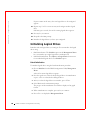
Ergonomic Computing Habits
CAUTION: Improper or prolonged keyboard use may result in
injury.
CAUTION: Viewing the monitor screen for extended periods of
time may result in eye strain.
Battery Disposal
Do not dispose of the battery along with household waste. Contact your
local waste disposal agency for the address of the nearest battery deposit
site.
5
6
w w w. d e l l . c o m | s u p p o r t . d e l l . c o m
Contents
Safety Instructions
. . . . . . . . . . . . . . . . . . . . . . . . .
1
PERC 3 Overview
. . . . . . . . . . . . . . . . . . . . . . . . . .
24
PERC 3 Features
. . . . . . . . . . . . . . . . . . . . . . . . . .
24
1 Overview
SCSI Channels
. . . . . . . . . . . . . . . . . . . . . . . . .
Non-volatile Random Access Memory (NVRAM) and Flash
Read-only Memory (ROM) . . . . . . . . . . . . . . . .
SCSI Connectors
25
. . .
25
. . . . . . . . . . . . . . . . . . . . . . . .
25
Single-Ended and LVD SCSI Buses
. . . . . . . . . . . . . . .
26
. . . . . . . . . .
26
. . . . . . . . . .
26
. . . . . . . . . . . . . . . . . . .
27
. . . . . . . . . . . . . . . . . . . . . . . . . .
30
Maximum Cable Length for SCSI Standards
SCSI Bus Widths and Maximum Throughput
Operating System Support
2 Introduction to RAID
RAID Definition .
. . . . . . . . . . . . . . . .
30
. . . . . . . . . . . . . . . . . . . . .
31
. . . . . . . . . . . . . . . . . . . . . . . . .
31
. . . . . . . . . . . . . . . . . . . . . . . . . .
31
PERC 3 Host-Based RAID Solution
Components and Features
Physical Array
Logical Drive
Fault Tolerance
. . . . . . . . . . . . . . . . . . . . . . . . .
Consistency Check .
Disk Striping
31
. . . . . . . . . . . . . . . . . . . . . . .
32
. . . . . . . . . . . . . . . . . . . . . . . . . .
32
Disk Mirroring
. . . . . . . . . . . . . . . . . . . . . . . . .
34
Disk Spanning
. . . . . . . . . . . . . . . . . . . . . . . . .
35
Spanning for RAID 10 or RAID 50
. . . . . . . . . . . . . . .
36
Contents
7
Parity
. . . . . . . . . . . . . . . . . . . . . . . . . . . . .
Hot Spares .
. . . . . . . . . . . . . . . . . . . . . . . . . .
37
. . . . . . . . . . . . . . . . . . . . . . . . .
38
. . . . . . . . . . . . . . . . . . . . . . . . . . .
39
Disk Rebuilds
Hot Swap
36
SCSI Drive States
. . . . . . . . . . . . . . . . . . . . . . .
Logical Drive States
. . . . . . . . . . . . . . . . . . . . . .
Enclosure Management
39
40
. . . . . . . . . . . . . . . . . . . .
40
. . . . . . . . . . . . . . . . . . . . . . . . . . . . . .
42
3 RAID Levels
Overview
. . . . . . . . . . . . . . . . . . . . . .
42
RAID 0
. . . . . . . . . . . . . . . . . . . . . . . . . . . . . . .
43
RAID 1
. . . . . . . . . . . . . . . . . . . . . . . . . . . . . . .
45
RAID 5
. . . . . . . . . . . . . . . . . . . . . . . . . . . . . . .
46
Selecting a RAID Level
RAID 10
. . . . . . . . . . . . . . . . . . . . . . . . . . . . . .
48
RAID 50
. . . . . . . . . . . . . . . . . . . . . . . . . . . . . .
50
4 PERC 3/SC Features
Hardware Requirements .
. . . . . . . . . . . . . . . . . . . . .
54
Configuration Features
. . . . . . . . . . . . . . . . . . . . . .
54
SMART Technology
. . . . . . . . . . . . . . . . . . . . . .
55
Configuration on Disk Configuration
. . . . . . . . . . . . . .
55
. . . . . . . . . . . . . . . . .
56
. . . . . . . . . . . . . . . . . . .
56
Hardware Architecture Features
Array Performance Features
PERC 3/SC Fault Tolerance Features
Software Utilities
. . . . . . . . . . . . . . .
57
. . . . . . . . . . . . . . . . . . . . . . . . .
57
Operating System Software Drivers .
8
Conte n ts
. . . . . . . . . . . . . . .
58
PERC 3/SC Specifications .
. . . . . . . . . . . . . . . . . . . .
58
PCI Bridge/CPU
. . . . . . . . . . . . . . . . . . . . . . . .
59
Cache Memory .
. . . . . . . . . . . . . . . . . . . . . . . .
59
PERC 3/SC BIOS
. . . . . . . . . . . . . . . . . . . . . . .
60
Onboard Speaker
. . . . . . . . . . . . . . . . . . . . . . .
60
Serial Port
. . . . . . . . . . . . . . . . . . . . . . . . . . .
60
SCSI Bus
. . . . . . . . . . . . . . . . . . . . . . . . . . .
60
SCSI Connectors .
. . . . . . . . . . . . . . . . . . . . . . .
60
SCSI Termination
. . . . . . . . . . . . . . . . . . . . . . .
60
. . . . . . . . . . . . . . . . . . . . . . . .
61
SCSI Firmware
RAID Management
. . . . . . . . . . . . . . . . . . . . . .
61
5 PERC 3/DC and PERC 3/DCL Features
Hardware Requirements .
. . . . . . . . . . . . . . . . . . . . .
64
Configuration Features
. . . . . . . . . . . . . . . . . . . . . .
64
SMART Technology
. . . . . . . . . . . . . . . . . . . . . .
65
Configuration on Disk
. . . . . . . . . . . . . . . . . . . . .
Hardware Architecture Features
. . . . . . . . . . . . . . . . .
66
. . . . . . . . . . . . . . . . . . .
67
. . . . . . . . . . . . . . . . . . . . .
67
. . . . . . . . . . . . . . . . . . . . . . . . .
68
Array Performance Features
Fault Tolerance Features .
Software Utilities
Operating System Software Drivers .
. . . . . . . . . . . . . . .
PERC 3/DC and PERC 3/DCL Specifications
68
PCI Bridge/CPU
. . . . . . . . . . . . . . . . . . . . . . . .
69
Cache Memory .
. . . . . . . . . . . . . . . . . . . . . . . .
70
. . . . . . . . . . . . . .
70
. . . . . . . . . . . . . . . . . . . . . . .
70
Serial Port
. . . . . . . . . . . . . . . . . . . . . . . . . . .
70
SCSI Bus
. . . . . . . . . . . . . . . . . . . . . . . . . . .
70
Onboard Speaker
Conte n ts
68
. . . . . . . . . . .
PERC 3/DC and PERC 3/DCL BIOS
9
65
SCSI Connectors .
. . . . . . . . . . . . . . . . . . . . . . .
71
SCSI Termination
. . . . . . . . . . . . . . . . . . . . . . .
71
SCSI Firmware
. . . . . . . . . . . . . . . . . . . . . . . .
RAID Management
. . . . . . . . . . . . . . . . . . . . . .
71
72
6 PERC 3/QC Features
Hardware Requirements .
. . . . . . . . . . . . . . . . . . . . .
74
Configuration Features
. . . . . . . . . . . . . . . . . . . . . .
74
SMART Technology
. . . . . . . . . . . . . . . . . . . . . .
75
Configuration on Disk
. . . . . . . . . . . . . . . . . . . . .
Hardware Architecture Features
. . . . . . . . . . . . . . . . .
76
. . . . . . . . . . . . . . . . . . .
76
. . . . . . . . . . . . . . . . . . . . .
77
. . . . . . . . . . . . . . . . . . . . . . . . .
77
Array Performance Features
Fault Tolerance Features .
Software Utilities
75
Operating System Software Drivers .
. . . . . . . . . . . . . . .
78
. . . . . . . . . . . . . . . . . . . .
78
PCI Bridge/CPU
. . . . . . . . . . . . . . . . . . . . . . . .
79
Cache Memory .
. . . . . . . . . . . . . . . . . . . . . . . .
79
PERC 3/QC Specifications
PERC 3/QC BIOS
. . . . . . . . . . . . . . . . . . . . . . .
80
Onboard Speaker
. . . . . . . . . . . . . . . . . . . . . . .
80
Serial Port
. . . . . . . . . . . . . . . . . . . . . . . . . . .
80
SCSI Bus
. . . . . . . . . . . . . . . . . . . . . . . . . . .
80
SCSI Connectors .
. . . . . . . . . . . . . . . . . . . . . . .
80
SCSI Termination
. . . . . . . . . . . . . . . . . . . . . . .
80
. . . . . . . . . . . . . . . . . . . . . . . .
81
SCSI Firmware
RAID Management
. . . . . . . . . . . . . . . . . . . . . .
81
7 Configuring PERC 3
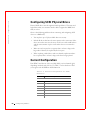
Configuring SCSI Physical Drives .
Current Configuration
. . . . . . . . . . . . . . . .
84
. . . . . . . . . . . . . . . . . . . . . . .
84
Logical Drive Configuration
10
Conte n ts
. . . . . . . . . . . . . . . . . . . .
87
Physical Device Layout
Configuring Arrays
. . . . . . . . . . . . . . . . . . . . . .
89
. . . . . . . . . . . . . . . . . . . . . . . .
92
. . . . . . . . . . . . . . . . . . . . . . .
93
Arranging Arrays
Creating Hot Spares
. . . . . . . . . . . . . . . . . . . . . .
Creating Logical Drives
93
. . . . . . . . . . . . . . . . . . . .
93
Configuration Strategies
. . . . . . . . . . . . . . . . . . . . .
93
Maximizing Capacity
. . . . . . . . . . . . . . . . . . . . .
94
Maximizing Drive Availability
. . . . . . . . . . . . . . . . .
94
. . . . . . . . . . . . . . . .
95
. . . . . . . . . . . . . . . . . . . . . .
95
Maximizing Drive Performance
Assigning RAID Levels
Configuring Logical Drives
Optimizing Data Storage
. . . . . . . . . . . . . . . . . . . .
96
. . . . . . . . . . . . . . . . . . . . .
96
. . . . . . . . . . . . . . . . . . .
96
. . . . . . . . . . . . . . . . . . . . . . . .
97
Data Access Requirements
Array Functions
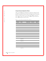
Planning the Array Configuration
. . . . . . . . . . . . . . . . .
Random Array Deletion
Overview
97
. . . . . . . . . . . .
98
. . . . . . . . . . . . . . . . . . . . . .
99
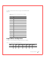
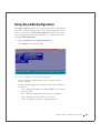
Using the Array Configuration Planner .
. . . . . . . . . . . . . . . . . . . . . . . . . . . .
Configuration Module
. . . . . . . . . . . . . . . . . . . . .
99
100
8 PERC 3/SC Hardware Installation
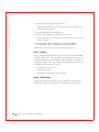
Requirements . . . . .
Optional Equipment
. . . . . . . . . . . . . . . . . . . . . .
. . . . . . . . . . . . . . . . . . . . . .
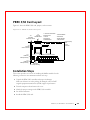
PERC 3/SC Card Layout .
Installation Steps
. . . . . . . . . . . . . . . . . . . . .
103
. . . . . . . . . . . . . . . . . . . . . . . . .
103
Step 1—Unpack
. . . . . . . . . . . . . . . . . . . . . . . .
Conte n ts
104
Step 2—Power Down
. . . . . . . . . . . . . . . . . . . . .
104
Step 3—Set Jumpers
. . . . . . . . . . . . . . . . . . . . .
105
Step 4—Set SCSI Termination .
11
102
102
. . . . . . . . . . . . . . . .
108
Step 5—Install PERC 3/SC
. . . . . . . . . . . . . . . . . .
Step 6—Connect SCSI Cables
Step 7—Set Target IDs
111
. . . . . . . . . . . . . . . . .
113
. . . . . . . . . . . . . . . . . . . .
114
Step 8—Power On Host System
. . . . . . . . . . . . . . . .
115
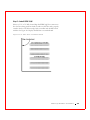
Step 9—Run PERC 3 BIOS Configuration Utility or WebBIOS
Utility . . . . . . . . . . . . . . . . . . . . . . . . . . . . . 116
Step 10—Install Operating System Software Drivers .
. . . . .
116
9 PERC 3/DC or PERC 3/DCL Hardware Installation
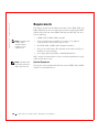
Requirements . . . . .
Optional Equipment
. . . . . . . . . . . . . . . . . . . . . .
. . . . . . . . . . . . . . . . . . . . . .
118
118
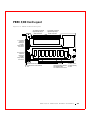
PERC 3/DC Card Layout .
. . . . . . . . . . . . . . . . . . . . .
119
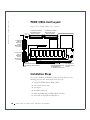
PERC 3/DCL Card Layout
. . . . . . . . . . . . . . . . . . . . .
120
. . . . . . . . . . . . . . . . . . . . . . . . .
120
Installation Steps
. . . . . . .
121
Step 2—Power Down
. . . . . . . . . . . . . . . . . . . . .
121
Step 3—Set Jumpers
. . . . . . . . . . . . . . . . . . . . .
121
Step 1—Unpack the PERC 3/DC or PERC 3/DCL
Step 4—Set SCSI Termination .
. . . . . . . . . . . . . . . .
Step 5—Install the PERC 3/DC or PERC 3/DCL Controller
. .
126
. . . . . .
128
. . . . . . . . . . . . . . . . .
128
Step 6—Select and Set Target IDs for SCSI Devices
Step 7—Connect SCSI Cables
125
Step 8—Power On Host System
. . . . . . . . . . . . . . . .
130
Step 9—Run the PERC 3 BIOS Configuration Utility or WebBIOS
Configuration Utility . . . . . . . . . . . . . . . . . . . . . 130
Step 10—Install Operating System Software Driver
. . . . . .
131
Replacing a PERC 3/DC Containing a BC Chip with a PERC 3/DC
Containing a BE Chip . . . . . . . . . . . . . . . . . . . . . . . 131
. .
131
. . . . . . . . . . . . .
131
Using Driver 5.22.1 or 5.22.2 and Firmware 161J or 161N
Using Driver 5.30 and Firmware 1.70
10 PERC 3/QC Hardware Installation
Requirements
12
Conte n ts
. . . . . . . . . . . . . . . . . . . . . . . . . . .
134
Optional Equipment
. . . . . . . . . . . . . . . . . . . . . .
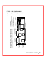
PERC 3/QC Card Layout .
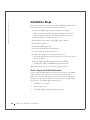
Installation Steps
134
. . . . . . . . . . . . . . . . . . . . .
135
. . . . . . . . . . . . . . . . . . . . . . . . .
136
. . . . . . . . . .
136
Step 2—Power Down
. . . . . . . . . . . . . . . . . . . . .
137
Step 3—Set Jumpers
. . . . . . . . . . . . . . . . . . . . .
137
Step 1—Unpack the PERC 3/QC Controller
Step 4—Set SCSI Termination .
SCSI Termination
. . . . . . . . . . . . . . . .
140
. . . . . . . . . . . . . . . . . . . . . . .
141
Step 5—Install PERC 3/QC
. . . . . . . . . . . . . . . . . .
Step 6—Connect SCSI Cables
Step 7—Set Target IDs
143
. . . . . . . . . . . . . . . . .
145
. . . . . . . . . . . . . . . . . . . .
146
Step 8—Power on Host System
. . . . . . . . . . . . . . . .
146
Step 9—Run the PERC 3 BIOS Configuration Utility or WebBIOS
Configuration Utility . . . . . . . . . . . . . . . . . . . . . . 147
Step 10—Install Operating System Driver
. . . . . . . . . . .
147
. . . . . . . . . . . . . . . . . . . . . . .
150
11 PERC 3 BIOS Configuration Utility
Configuration On Disk
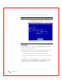
Starting the PERC 3 BIOS Configuration Utility
. . . . . . . . .
150
. . . . . . . . . . . .
151
Configure Menu
. . . . . . . . . . . . . . . . . . . . . . . .
152
Initialize Menu
. . . . . . . . . . . . . . . . . . . . . . . .
153
Objects Menu
. . . . . . . . . . . . . . . . . . . . . . . . .
153
Format Menu
. . . . . . . . . . . . . . . . . . . . . . . . .
158
Rebuild Menu
. . . . . . . . . . . . . . . . . . . . . . . . .
158
BIOS Configuration Utility Menu Options
Check Consistency Menu
. . . . . . . . . . . . . . . . . . . .
Configuring Arrays and Logical Drives
. . . . . . . . . . . . . .
159
. . . . . . . . . . . . . . .
160
. . . . . . . . . . . . . . . . . . . . . .
160
. . . . . . . . . . . . . . . . . . . . . . .
160
Choosing the Configuration Method
Easy Configuration .
New Configuration
View/Add Configuration
13
Conte n ts
159
. . . . . . . . . . . . . . . . . . . .
161
PERC 3/QC and PERC 3/DC Default Settings
. . . . . . . . .
PERC 3/SC and PERC 3/DCL Default Settings .
161
. . . . . . . .
161
. . . . . . . . . . .
162
. . . . . . . . . . . . . . . . .
162
Using Easy Configuration
. . . . . . . . . . . . . . . . . . . . .
163
Using New Configuration
. . . . . . . . . . . . . . . . . . . . .
167
Reserved Disk Space during Configuration
Designating Drives as Hot Spares
Using View/Add Configuration
Initializing Logical Drives
Batch Initialization .
. . . . . . . . . . . . . . . . . .
173
. . . . . . . . . . . . . . . . . . . . .
. . . . . . . . . . . . . . . . . . . . .
178
178
. . . . . . . . . . . . . . . . . . . .
179
Individual Initialization
Deleting Logical Drives (Random Array Deletion) .
. . . . . . . .
179
. . . . . . . . . . . . . . . . . . . .
180
. . . . . . . . . . . . . . . . . . . . . . . . .
180
Formatting Physical Drives
Media Errors
Formatting Drives
. . . . . . . . . . . . . . . . . . . . . . .
Rebuilding Failed Disk Drives
. . . . . . . . . . . . . . . . . . .
. . . . . . .
182
182
Using a Pre-loaded SCSI Drive “As-is”
. . . . . . . . . . . . . .
Exiting the PERC 3 BIOS Configuration Utility
183
. . . . . . . . .
184
. . . . . . . . . . . . . . . . . .
184
. . . . . . . . . . . . . . . . . . . . . . . . . . . . .
185
Setting Hardware Termination
Clustering
182
. . . . . . . . . . . . . . . . .
Manual Rebuild – Rebuilding an Individual Drive .
Manual Rebuild – Batch Mode
180
Cluster Mode
. . . . . . . . . . . . . . . . . . . . . . . . .
185
. . . . . . . . . . .
185
. . . . . . . . . . . . . . . . . .
188
189
Enabling and Disabling the Cluster Mode
12 Dell Manager
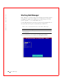
Starting Dell Manager . . . . .
Management Menu Options
. . . . . . . . . . . . . . . . . .
Using Dell Manager in Red Hat Linux GUI Mode
14
Conte n ts
. . . . . . .
189
Dell Manager Menu Options
. . . . . . . . . . . . . . . . . . .
190
. . . . . . . . . . . . . . . . . . . . . . . .
190
Objects Menu
. . . . . . . . . . . . . . . . . . . . . . . . .
190
Format Menu
. . . . . . . . . . . . . . . . . . . . . . . . .
194
Rebuild Menu
. . . . . . . . . . . . . . . . . . . . . . . . .
195
Initialize Menu
Check Consistency Menu
Reconstruct Menu .
. . . . . . . . . . . . . . . . . . .
195
. . . . . . . . . . . . . . . . . . . . . .
195
Designating Drives as Hot Spares
Parameters
. . . . . . . . . . . . . . . .
195
. . . . . . . . . . . . . . . . . . . . . . . . . . . .
196
Initializing Logical Drives
Batch Initialization
. . . . . . . . . . . . . . . . . . . .
197
. . . . . . . . . . . . . . . . . . . . . .
197
Individual Initialization
. . . . . . . . . . . . . . . . . . . .
Deleting Logical Drives (Random Array Deletion)
. . . . . . . .
198
. . . . . . . . . . . . . . . . . . . .
199
. . . . . . . . . . . . . . . . . . . . . . . . .
199
Formatting Physical Drives
Media Errors
198
Formatting Drives .
. . . . . . . . . . . . . . . . . . . . . .
Rebuilding Failed Disk Drives .
. . . . . . . . . . . . . . . . . .
200
201
. . . . . . .
201
. . . . . . . . . . . . . . . .
202
. . . . . . . . . . . . . . . . . . . . . . .
202
. . . . . . . . . . . . . . . . . . . . . . . . . . . . .
204
Manual Rebuild – Rebuilding an Individual Drive
Manual Rebuild – Batch Mode
Exiting Dell Manager
13 Troubleshooting
Overview
. . . . . . . . . . . . . . . . . . . .
205
. . . . . . . . . . . . . . . . . . .
208
. . . . . . . . . . . . . . . . . . . .
209
. . . . . . . . . . . . . . . . . . . . . . . . .
210
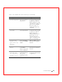
BIOS Boot Error Messages
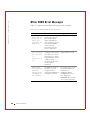
Other BIOS Error Messages
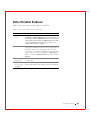
Other Potential Problems .
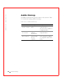
Audible Warnings
Contents
15
14 Appendix A: SCSI Cables and Connectors
15 Appendix B: Warranties and Return Policy
Glossary
Index
16
Conte n ts
. . . . . . . . . . . . . . . . . . . . . . . . . . . . . . . .
237
. . . . . . . . . . . . . . . . . . . . . . . . . . . . . . . . . .
247
Figures
Figure 2-1. Example of Disk Striping
. . . . . . . . . . . . . . . .
33
Figure 2-2. Example of Disk Mirroring
. . . . . . . . . . . . . . .
34
Figure 2-3. Example of Disk Spanning
. . . . . . . . . . . . . . . .
35
. . . . . . . . . . . . . . . . . . . .
37
Figure 3-1. RAID 0 Array
. . . . . . . . . . . . . . . . . . . . . .
44
Figure 3-2. RAID 1 Array
. . . . . . . . . . . . . . . . . . . . . .
46
Figure 3-3. RAID 5 Array
. . . . . . . . . . . . . . . . . . . . . .
48
Figure 3-4. RAID 10 Array
. . . . . . . . . . . . . . . . . . . . .
50
Figure 3-5. RAID 50 Array
. . . . . . . . . . . . . . . . . . . . .
52
Figure 2-4. Example of Parity
Figure 8-1. PERC 3/SC Card Layout
. . . . . . . . . . . . . . .
Figure 8-2. Example of SCSI Termination
. . . . . . . . . . . . .
Figure 8-3. Termination of Internal SCSI Disk Arrays
Figure 8-4. PCI Slots on Motherboard
103
108
. . . . . . .
110
. . . . . . . . . . . . . . .
111
. . .
112
. . . . . . . . . . . . . . . .
113
Figure 9-1. PERC 3/DC Card Layout
. . . . . . . . . . . . . . .
119
Figure 9-2. PERC 3/DCL Card Layout
. . . . . . . . . . . . . . .
120
. . . . . . . . . . . . . . . .
123
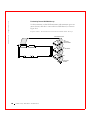
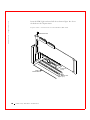
Figure 8-5. Installation of PERC 3/SC Card into Motherboard
Figure 8-6. Connecting SCSI Cables
Figure 9-3. J11 Serial Port Pinout
Figure 9-4. Termination of Internal SCSI Disk Arrays for PERC 3/DC and
3/DCL . . . . . . . . . . . . . . . . . . . . . 126
Figure 9-5. Installation of the PERC 3/DC and 3/DCL
. . . . . . .
127
. .
129
Figure 10-1. PERC 3/QC Card Layout
. . . . . . . . . . . . . . .
135
Figure 10-2. J14 Serial Port Diagram
. . . . . . . . . . . . . . .
139
Figure 10-3. Example of Termination
. . . . . . . . . . . . . . .
141
Figure 9-6. Connecting SCSI Cables to PERC 3/DC and 3/DCL
Figure 10-4. Termination of Internal SCSI Disk Arrays
Figure 10-5. PCI Slots on Motherboard
. . . . . .
142
. . . . . . . . . . . . . .
143
. . . . . . . . .
144
. . . . . . . . . . . . . . .
145
Figure 10-6. Installation of the PERC 3/QC Card
Figure 10-7. Connecting SCSI Cables
Figures
17
18
F i g u re s
Tables
Table 1-1. Maximum Cable Length for SCSI Standards
. . . . . .
26
Table 1-2. SCSI Bus Widths and Maximum Throughput
. . . . . .
27
. . . . . . . . . .
36
. . . . . . . . . . . . . . . . . . . . .
36
Table 2-1. Spanning for RAID 10 and RAID 50
Table 2-2. Types of Parity
. . . . . . . . . . . . . . . . . . .
39
. . . . . . . . . . . . . . . . . .
40
. . . . . . . . . . . . . . . . . . . . . .
42
Table 2-3. SCSI Drive States
Table 2-4. Logical Drive States
Table 3-1. RAID Levels
Table 3-2. RAID 0 Overview
. . . . . . . . . . . . . . . . . . . .
43
Table 3-3. RAID 1 Overview
. . . . . . . . . . . . . . . . . . . .
45
Table 3-4. RAID 5 Overview
. . . . . . . . . . . . . . . . . . . .
47
Table 3-5. RAID 10 Overview
. . . . . . . . . . . . . . . . . . .
49
Table 3-6. RAID 50 Overview
. . . . . . . . . . . . . . . . . . .
51
Table 4-1. Configuration Features
. . . . . . . . . . . . . . . . .
. . . . . . . . . . . . .
55
. . . . . . . . . . . .
56
. . . . . . . . . . . . . .
56
Table 4-2. Configuration on Disk Features
Table 4-3. Hardware Architecture Features
Table 4-4. Array Performance Features
54
. . . . . . . . . .
57
Table 4-6. Software Utilities Features
. . . . . . . . . . . . . . .
57
Table 4-7. PERC 3/SC Specifications
. . . . . . . . . . . . . . .
58
. . . . . . . . . . . . . . . .
61
. . . . . . . . . . . . . . . . .
64
Table 4-5. PERC 3/SC Fault Tolerance Features
Table 4-8. SCSI Firmware Support
Table 5-1. Configuration Features
Table 5-2. Configuration on Disk Features
. . . . . . . . . . . . .
65
. . . . . . . . . . . .
66
. . . . . . . . . . . . . .
67
. . . . . . . . . . . . . . . .
67
. . . . . . . . . . . . . . . . . . .
68
Table 5-3. Hardware Architecture Features
Table 5-4. Array Performance Features
Table 5-5. Fault Tolerance Features
Table 5-6. Software Utilities
Table 5-7. PERC 3/DC and PERC 3/DCL Specifications
Table 5-8. SCSI Firmware
. . . . . .
68
. . . . . . . . . . . . . . . . . . . .
71
Table 6-1. Configuration Features
. . . . . . . . . . . . . . . . .
Table 6-2. Configuration on Disk Features
. . . . . . . . . . . . .
74
75
Tables
19
Table 6-3. Hardware Architecture Features
. . . . . . . . . . . . .
76
. . . . . . . . . . . . . .
76
. . . . . . . . . . . . . . . .
77
. . . . . . . . . . . . . . . . . . . .
78
Table 6-4. Array Performance Features
Table 6-5. Fault Tolerance Features
Table 6-6. Software Utilities
Table 6-7. PERC 3/QC Specifications
Table 6-8. SCSI Firmware
. . . . . . . . . . . . . . . .
78
. . . . . . . . . . . . . . . . . . . . .
81
Table 7-1. Current Configuration for SCSI Channel 0
. . . . . . . .
84
Table 7-2. Current Configuration for SCSI Channel 1
. . . . . . . .
85
Table 7-3. Current Configuration for SCSI Channel 2
. . . . . . . .
86
Table 7-4. Current Configuration for SCSI Channel 3
. . . . . . . .
87
. . . . . . . . . . . . . . .
87
. . . . . . . . . . . . . . . . .
89
Table 7-5. Logical Drive Configuration
Table 7-6. Physical Device Layout
Table 7-7. Drives and Capacities for Each RAID Level
. . . . . . .
Table 7-8. Fault Tolerance Features for RAID Levels 0, 1 and 5
. .
94
. . . .
95
. . . . .
95
. . . . . .
97
. . . . . . . . . . . . . .
98
Table 7-9. Performance Characteristics for Each RAID Level
Table 7-10. Physical Drives Required for Each RAID Level
Table 7-11. Factors to Consider for Array Configuration
Table 7-12. Array Configuration Planner
Table 8-1. PERC 3/SC Jumpers
. . . . . . . . . . . . . . . . .
Table 8-2. J1 Termination Enable Settings
. . . . . . . . . . . .
. . . . . . . . . . . . . . . . .
106
. . . . . . . . . . . . . . . . . .
107
Table 8-6. J15 RUBI Slot Interrupt Steering
. . . . . . . . . . .
Table 8-7. J16, J17 RUBI Slot Interrupt Steering
108
. . . . . . . . . . . . . . . . . . . . . . .
115
. . . . . . . . . . . . . . . . . . . .
Table 9-2. J2 and J3 Termination Enable Settings
122
. . . . . . . . . . .
122
. . . . . . . . . . . . . .
123
. . . . . . . . . . . . . . . .
123
Table 9-4. J10 NVRAM Clear Pinout
Table 9-5. J11 Serial Port Pinout
121
. . . . . . . .
Table 9-3. J9 Onboard BIOS Enable Settings
Ta b l e s
107
. . . . . . . .
Table 9-1. Jumper Settings
20
105
106
Table 8-4. J5 Serial Port Pinout
Table 8-8. Target IDs
105
. . . . . . . . . .
Table 8-3. J9 I2C Interface Connector Pinout
Table 8-5. J8 Hard Disk LED
94
Table 9-6. J13 Dirty Cache LED Pinout
Table 9-7. J14 SCSI Activity Pinout
. . . . . . . . . . . . . .
124
. . . . . . . . . . . . . . . .
124
. . . . . . .
124
. . . . . . . . . . . . . . .
125
Table 9-8. J16 and J18 TERMPWR Enable Settings
Table 9-9. J17 I2C Connector Pinout
Table 9-10. Target IDs for SCSI Devices
. . . . . . . . . . . . .
128
Table 10-1. PERC 3/QC Jumper Settings
. . . . . . . . . . . . .
137
Table 10-2. J2, J3, J5 and J7 Termination Enable Pinout
. . . . .
Table 10-3. J9, J10, J11 and J12 TERMPWR Enable Pinout
Table 10-4. J14 Serial Port Pinout
. . .
138
. . . . . . . . . . . . . . . .
139
Table 10-5. J17 Dirty Cache LED Pinout
. . . . . . . . . . . . .
Table 10-6. J19 Onboard BIOS Enable Settings
139
. . . . . . . . . .
140
. . . . . . . . . . . . .
140
. . . . . . . . . . . . . . . . . . . . . .
146
Table 10-7. J23 External Battery Pinout
Table 10-8. Target IDs
138
Table 11-1. BIOS Configuration Utility Menu Options
. . . . . . .
151
. . . . . . . . . . . . . .
152
. . . . . . . . . . . . . . . .
153
Table 11-2. Configuration Menu Options
Table 11-3. Adapter Menu Options
Table 11-4. Logical Drive Menu Options
. . . . . . . . . . . . . .
155
Table 11-5. Physical Drive Menu Options
. . . . . . . . . . . . .
156
Table 11-6. SCSI Channel Menu Options
. . . . . . . . . . . . .
157
Table 11-7. Battery Information Menu Options
. . . . . . . . . .
. . . . .
161
. . . .
161
. . . . . . . . . . . . . . . . . . . .
182
Table 11-8. PERC 3/QC and PERC 3/DC Default Settings
Table 11-9. PERC 3/SC and PERC 3/DCL Default Settings
Table 11-10. Rebuild Types
157
. . . . . . . .
188
. . . . . . . . . . . . . .
189
. . . . . . . . . . . . . . . .
190
Table 12-1. Command Used to Start Dell Manager
Table 12-2. Management Menu Options
Table 12-3. Adapter Menu Options
Table 12-4. Logical Drive Menu Options
. . . . . . . . . . . . . .
191
Table 12-5. Logical Drive Default Settings
. . . . . . . . . . . . .
191
Table 12-6. Physical Drive Menu Options
. . . . . . . . . . . . .
192
. . . . . . . . . . . . . . . . .
193
Table 12-7. SCSI Channel Options
Table 12-8. Battery Backup Menu Items
. . . . . . . . . . . . .
193
Tables
21
Table 12-9. Rebuild Types
. . . . . . . . . . . . . . . . . . . .
Table 13-1. General Problems and Suggested Solutions
. . . . . .
204
Table 13-2. BIOS Boot Error Messages
. . . . . . . . . . . . .
205
Table 13-3. Other BIOS Error Messages
. . . . . . . . . . . . .
208
. . . . . . . . . . . . . .
209
. . . . . . . . . . . . . . . . . .
210
Table 13-4. Other Potential Problems
Table 13-5. Audible Warnings
22
Ta b l e s
201
SECTION 1
Overview
PERC 3 Overview
PERC 3 Features
w w w. d e l l . c o m | s u p p o r t . d e l l . c o m
PERC 3 Overview
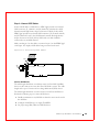
The Dell™ PowerEdge™ Expandable RAID Controller 3 (PERC 3) PCI
card is a high-performance, intelligent peripheral component interconnect
(PCI)-to-SCSI host adapter with RAID control capabilities. PERC 3
provides system availability, high performance, and fault-tolerant disk
subsystem management. PERC 3 is an ideal RAID solution for the internal
storage of Dell’s workgroup, departmental, and enterprise systems. PERC 3
offers a cost-effective way to implement RAID in a server.
The PERC 3/QC low voltage differential (LVD) PCI RAID card provides
four SCSI channels. The PERC 3/DC and PERC 3/DCL LVD PCI RAID
card provides two SCSI channels. The PERC 3/SC LVD PCI RAID card
provides one SCSI channel.
NOTE: The information
in this document applies
to PERC 3/QC, PERC
3/DC, PERC 3/DCL and
PERC 3/SC.
With LVD, you can use cables up to 25 meters long. Throughput on each
SCSI channel can be as high as 160 MB/s. PERC 3 supports both an LVD
SCSI bus and a single-ended SCSI bus.
PERC 3 64-bit LVD is a high-performance, intelligent PCI-to-SCSI host
adapter with RAID control capabilities. PERC 3 64-bit LVD requires no
special motherboard PCI expansion slot.
PERC 3 Features
The PERC 3 features include:
24
Ov e r v ie w
•
Wide Ultra3 LVD SCSI performance of up to 160 MB/s
•
PERC 3/QC and PERC 3/DC support 128 MB of synchronous
dynamic random access memory (SDRAM.)
•
The PERC 3/DCL supports 64 MB of SDRAM.
•
The PERC 3/SC supports 32 MB of SDRAM.
•
64-bit PCI host interface (only on PERC 3/QC and PERC 3/DC)
•
The PERC 3/QC, PERC 3/DC and PERC 3/DCL have an on-board
i960RN processor to improve controller performance and offload host
Central Processing Unit (CPU.)
•
The PERC 3/SC has a on-board i960RM processor to improve
controller performance and offload host CPU.
•
Two internal and four external connectors for the PERC 3/QC, two
internal and two external connectors for the PERC 3/DC and PERC
3/DCL, and one internal and one external connector for the PERC
3/SC
•
RAID levels 0 (striping), 1 (mirroring), 5 (distributed parity), 10
(combination of striping and mirroring), and 50 (combination of
striping and distributed parity)
•
Advanced array configuration and management utilities
•
Battery backup for up to 72 hours for the PERC 3/QC and PERC
3/DC
•
Up to 12 SCSI drives per channel using the Dell PowerVault 21xS
storage system or 14 SCSI drives using the Dell PowerVault 22xS
NOTE: Clustering is not
supported by PERC 3/QC
or PERC 3/DCL.
SCSI Channels
The PERC 3/QC controller card includes four SCSI channels. There are two
QLogic®12160 chips; each chip controls two SCSI channels.
The PERC 3/DC and PERC 3/DCL controller cards include two SCSI
channels. There is one QLogic 12160 chip, which controls two SCSI
channels.
The PERC 3/SC controller card has one SCSI channel. There is one QLogic
10160 chip.
Non-volatile Random Access Memory (NVRAM) and Flash Readonly Memory (ROM)
A 32 KB x 8 NVRAM stores RAID system configuration information. The
PERC 3 firmware is stored in flash ROM for easy upgrade.
SCSI Connectors
PERC 3/QC has four ultra-high-density 68-pin external connectors for the
external storage subsystem and two high-density 68-pin internal connectors.
PERC 3/DC and PERC 3/DCL have two ultra-high-density 68-pin external
connectors for the external storage subsystem and two high-density 68-pin
internal connectors.
Over view
25
w w w. d e l l . c o m | s u p p o r t . d e l l . c o m
PERC 3/SC has one ultra-high-density 68-pin external connector for the
external storage subsystem and one high-density 68-pin internal connector.
Single-Ended and LVD SCSI Buses
The SCSI standard defines two electrical buses: a single-ended bus and an
LVD bus. PERC 3 supports both standards.
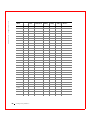
Maximum Cable Length for SCSI Standards
Table 1-1 displays the maximum length of cable that you can use for various
SCSI standards.
Ta b l e 1 - 1 . M a x i m u m C a b l e L e n g t h f o r S C S I S t a n d a r d s
SCSI Standard
Single-ended
LVD
Maximum # of
Drives
SCSI I
6m
12 m
7
Fast SCSI
6m
12 m
7
Fast Wide SCSI
6m
12 m
15
Ultra SCSI
1.5 m
12 m
7
Ultra SCSI
3m
12 m
3
Wide Ultra SCSI
N/A
12 m
15
Wide Ultra SCSI
1.5 m
12 m
7
Wide Ultra SCSI
3m
12 m
3
Ultra 2 SCSI
N/A
25 m
1
Ultra 2 SCSI
N/A
12 m
7
Wide Ultra 2 SCSI
N/A
25 m
1
Wide Ultra 2 SCSI
N/A
12 m
15
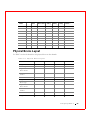
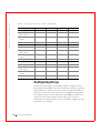
SCSI Bus Widths and Maximum Throughput
Table 1-2 displays the SCSI bus widths and maximum throughput for each
of the SCSI standards.
26
Ov e r v ie w
Ta b l e 1 - 2 . S C S I B u s W i d t h s a n d M a x i m u m T h r o u g h p u t
SCSI Standard
SCSI Bus Width
SCSI Throughput
SCSI I
8 bits
5 MB/s
Fast SCSI
8 bits
10 MB/s
Fast Wide SCSI
16 bits
20 MB/s
Ultra SCSI
8 bits
20 MB/s
Wide Ultra SCSI
16 bits
40 MB/s
Ultra 2 SCSI
8 bits
40 MB/s
Wide Ultra 2 SCSI
16 bits
80 MB/s
160M SCSI
8 bits
80 MB/s
Wide 160M SCSI
16 bits
160 MB/s
Operating System Support
PERC 3 supports the following operating systems:
•
Microsoft® Windows® 2000: Server, Advanced Server, Small Business
Server
•
Microsoft Windows NT® 4: Server, Terminal Server, Enterprise Server,
Small Business Server
•
Microsoft NET: Server, Advanced Server
•
Microsoft SBS 2000
•
Novell® NetWare® 5.x, 6.x
•
Red Hat Linux 7.x
•
DOS, including ASPI® support
Over view
27
28
Ov e r v ie w
w w w. d e l l . c o m | s u p p o r t . d e l l . c o m
SECTION 2
Introduction to RAID
RAID Definition
PERC 3 Host-Based RAID Solution
Components and Features
w w w. d e l l . c o m | s u p p o r t . d e l l . c o m
RAID Definition
RAID is an array of multiple independent hard disk drives that provides
high performance and fault tolerance. The RAID array appears to the host
computer as a single storage unit or as multiple logical units. Input/output
(I/O) improves because several disks can be accessed simultaneously.
Although hard drive capabilities have improved drastically, actual
performance has improved only three to four times in the last decade. In
comparison, computing performance has improved over 50 times during the
same time period. Implementing RAID improves the performance of the
disk subsystem.
RAID systems also improve data storage availability and fault tolerance.
Data loss caused by a hard drive failure can be recovered by reconstructing
missing data from the remaining data and parity drives.
PERC 3 Host-Based RAID Solution
PERC 3 is a peripheral component interconnect (PCI) adapter card that is
installed in any available PCI expansion slot in a host system. It is a hostbased RAID solution, meaning that the RAID controller puts all of the
RAID intelligence on an adapter card that is installed in a network server.
The array controller resides on the bus (for example, a PCI or EISA bus) in
the host computer and has its own central processing unit (CPU) to
generate the parity and handle other RAID functions. A bus-based
controller can transfer data at the speed of the host bus (PCI, ISA, EISA,
VL-Bus), but is limited to the bus it is designed for. PERC 3 resides on a
PCI bus, which can handle data transfer at up to 528 MB/s. With PERC 3,
each channel can handle data transfer rates up to 160 MB/s per SCSI
channel. The available sequential data transfer rate is determined by the
following factors:
30
In t ro duc ti o n to RAI D
•
The sustained data transfer rate on the motherboard PCI bus
•
The sustained data transfer rate on the i960RN (i960RM for the PERC
3/SC) PCI to PCI bridge
•
The sustained data transfer rate of the SCSI controller
•
The sustained data transfer rate of the SCSI devices
•
The number of SCSI channels and SCSI hard drives
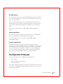
Components and Features
RAID versions, or levels, are specifications that describe a system for
ensuring the availability and stability of data stored on large disk
subsystems. A RAID system can be implemented in a number of different
levels). PERC 3 supports RAID levels 0, 1, 5, 10 (1+0), and 50 (5+0).
Physical Array
A RAID array is a collection of physical disk drives governed by the RAID
management software. A RAID array appears to the host computer as one or
more logical drives.
Logical Drive
A logical drive is a partition in a physical array of disks that is made up of
contiguous data segments on the physical disks. A logical drive can consist
of an entire physical array, more than one entire physical array, a part of an
array, parts of more than one array, or a combination of any two of these
conditions.
Fault Tolerance
Fault tolerance is the capability of the subsystem to undergo a single failure
without compromising data integrity, and processing capability. The RAID
controller provides this support through redundant arrays in RAID levels 1,
5, 10 and 50. The system can still work properly even with a single disk
failure in an array, through performance can be degraded to some extent.
Fault tolerance is often associated with system availability (high mean time
between failure, MTFB) because it allows the system to be available during
the failures. However, this means it is also important for the system to be
available during the repair of the problem. To make this possible, PERC 3
supports hot spare disks, and the auto-rebuild feature.
I n tr o d uc t io n t o RA I D
31
w w w. d e l l . c o m | s u p p o r t . d e l l . c o m
A hot spare is an unused online disk that, in case of a disk failure in a
redundant RAID array, can be used to rebuild the data and re-establish
redundancy. After the hot spare is automatically moved into the RAID
subsystem, the failed drive is automatically rebuilt on the spare drive. The
RAID disk array continues to handle requests while the rebuild occurs.
Auto-rebuild allows a failed drive to be replaced and automatically rebuilt
by “hot-swapping” the drive in the same drive bay. The RAID disk array
continues to handle requests while the rebuild occurs.
Consistency Check
In RAID, check consistency verifies the correctness of redundant data in an
array. For example, in a system with parity, checking consistency means
computing the data on one drive and comparing the results to the contents
of the parity drive.
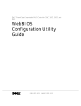
Disk Striping
Disk striping allows you to write data across multiple disk drives instead of
just one disk drive. Disk striping involves partitioning each drive storage
space into stripes that can vary in size from 2 KB to 128 KB. These stripes
are interleaved in a repeated sequential manner. The combined storage
space is composed of stripes from each drive. PERC 3 supports stripe sizes
of 2 KB, 4 KB, 8 KB, 16 KB, 32 KB, 64 KB, and 128 KB.
For example, in a four-disk system using only disk striping (as in RAID level
0), segment 1 is written to disk 1, segment 2 is written to disk 2, and so on.
Disk striping enhances performance because multiple drives are accessed
simultaneously, but disk striping does not provide data redundancy.
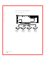
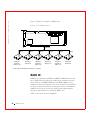
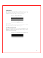
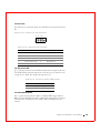
Figure 2-1 shows an example of disk striping.
32
In t ro duc ti o n to RAI D
Figure 2-1. Example of Disk Striping
Segment 1
Segment 5
Segment 9
Segment 2
Segment 6
Segment 10
Segment 3
Segment 7
Segment 11
Segment 4
Segment 8
Segment 12
Stripe Width
Stripe width is the number of disks involved in an array where striping is
implemented. For example, a four-disk array with disk striping has a stripe
width of four.
Stripe Size
The stripe size is the length of the interleaved data segments that PERC 3
writes across multiple drives. PERC 3 supports stripe sizes of 2 KB, 4 KB,
8 KB, 16 KB, 32 KB, 64 KB, or 128 KB.
I n tr o d uc t io n t o RA I D
33
w w w. d e l l . c o m | s u p p o r t . d e l l . c o m
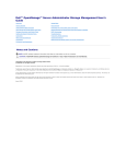
Disk Mirroring
With mirroring (used in RAID 1), data written to one disk is simultaneously
written to another disk. If one disk fails, the contents of the other disk can
be used to run the system and reconstruct the failed disk. The primary
advantage of disk mirroring is that it provides 100% data redundancy.
Because the contents of the disk are completely written to a second disk, it
does not matter if one of the disks fails. Both disks contain the same data at
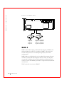
all times. Either drive can act as the operational drive.
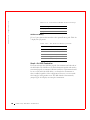
Disk mirroring provides 100% redundancy, but is expensive because each
drive in the system must be duplicated.
Figure 2-2. Example of Disk Mirroring
Segment 1
Segment 2
Segment 3
Segment 4
34
In t ro duc ti o n to RAI D
Segment 1 Duplicated
Segment 2 Duplicated
Segment 3 Duplicated
Segment 4 Duplicated
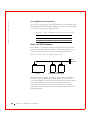
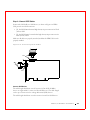
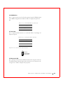
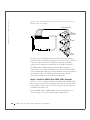
Disk Spanning
Disk spanning allows multiple physical drives to function like one big drive.
Spanning overcomes lack of disk space and simplifies storage management
by combining existing resources or adding relatively inexpensive resources.
For example, four 20 GB drives can be combined to appear to the operating
system as a single 80 GB drive.
Spanning alone does not provide reliability or performance enhancements.
Spanned logical drives must have the same stripe size and must be
contiguous. In the following graphic, RAID 1 array is turned into a RAID 10
array.
Figure 2-3. Example of Disk Spanning
60 GByte
60 GByte
Can Be Accessed as
One 120 GByte Drive
60 GByte
60 GByte
Can Be Accessed as
One 120 GByte Drive
I n tr o d uc t io n t o RA I D
35
w w w. d e l l . c o m | s u p p o r t . d e l l . c o m
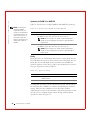
Spanning for RAID 10 or RAID 50
Table 2-1 describes how to configure RAID 10 and RAID 50 by spanning.
NOTE: Spanning two
contiguous RAID 0
logical drives does not
produce a new RAID level
or add fault tolerance. It
does increase the size of
the logical volume and
improves performance by
doubling the number of
spindles.
Ta b l e 2 - 1 . S p a n n i n g f o r R A I D 1 0 a n d R A I D 5 0
Level
Description
10
Configure RAID 10 by spanning two contiguous RAID 1 logical drives.
The RAID 1 logical drives must have the same stripe size.
NOTE: Refer to Chapter 11 "PERC 3 BIOS Configuration
Utility" for the configuration procedure for spanning RAID 1
logical drives.
50
Configure RAID 50 by spanning two contiguous RAID 5 logical drives.
The RAID 5 logical drives must have the same stripe size.
NOTE: Refer to Chapter 11 "PERC 3 BIOS Configuration
Utility" for the configuration procedure for spanning RAID 5
logical drives.
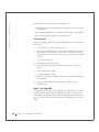
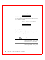
Parity
Parity generates a set of redundancy data from two or more parent data sets.
The redundancy data can be used to reconstruct one of the parent data sets.
Parity data does not fully duplicate the parent data sets. In RAID, this
method is applied to entire drives or stripes across all disk drives in an array.
The types of parity are shown in Table 2-2.
Ta b l e 2 - 2 . Ty p e s o f P a r i t y
Parity Type
Description
Dedicated
The parity of the data on two or more disk drives is stored on an
additional disk.
Distributed
The parity data is distributed across all drives in the system.
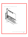
If a single disk drive fails, it can be rebuilt from the parity and the data on
the remaining drives. RAID level 5 combines distributed parity with disk
striping. Parity provides redundancy for one drive failure without
duplicating the contents of entire disk drives, but parity generation can slow
the write process. A dedicated parity scheme during normal read/write
operations is shown in Figure 2-4.
36
In t ro duc ti o n to RAI D
Figure 2-4. Example of Parity
Parity
Generator
Hot Spares
A hot spare is an extra, unused disk drive that is part of the disk subsystem.
It is usually in standby mode, ready for service if a drive fails. Hot spares
permit you to replace failed drives without system shutdown or user
intervention.
PERC 3 implements automatic and transparent rebuilds using hot spare
drives, providing a high degree of fault tolerance and zero downtime. The
PERC 3 RAID management software allows you to specify physical drives as
hot spares. When a hot spare is needed, PERC 3 assigns the hot spare that
has a capacity closest to and at least as great as that of the failed drive to
take the place of the failed drive.
I n tr o d uc t io n t o RA I D
37
w w w. d e l l . c o m | s u p p o r t . d e l l . c o m
NOTE: Refer to Chapter
11 "PERC 3 BIOS
Configuration Utility" for
the procedures used to
designate a drive as a hot
spare.
There are two types of hot spares:
•
Global Hot Spare
•
Dedicated Hot Spare
Global Hot Spare
A global hot spare drive can be used to replace any failed drive in a
redundant array as long as its capacity is equal to or larger than the coerced
capacity of the failed drive. A global hot spare defined on any channel
should be available to replace a failed drive on both channels.
Dedicated Hot Spare
A dedicated hot spare can be used to replace a failed drive only in a selected
array. One or more drives can be designated as member of a spare drive pool;
the most suitable drive from the pool is selected for fail over. A dedicated
hot spare is used before one from the global hot spare pool.
NOTE: Refer to Chapter
11"PERC 3 BIOS
Configuration Utility" for
the procedures used to
designate a drive as a hot
spare.
Hot spare drives can be located on any RAID channel. Standby hot spares
(not being used in RAID array) are polled every 60 seconds at a minimum,
and their status made available in the array management software. PERC 3
offers the ability to rebuild with a disk that is in a system, but not initially
set to be a hot spare.
Observe the following parameters when using hot spares:
•
Hot spares are used only in arrays with redundancy, for example, RAID
levels 1, 5, 10, and 50.
•
A hot spare connected to a specific PERC 3 controller can be used to
rebuild a drive that is connected to the same controller only.
•
You must assign the hot spare to one or more drives through the
controller’s BIOS or use array management software to place it in the
hot spare pool.
•
A hot spare must have free space equal to or greater than the drive it
would replace. For example, to replace an 18 GB drive, the hot spare
must be 18 GB or larger.
Disk Rebuilds
You can rebuild a disk drive by recreating the data that had been stored on
the drive before the drive failed.
38
In t ro duc ti o n to RAI D
Rebuilding can be done only in arrays with data redundancy, which includes
as RAID 1, 5, 10 and 50.
A hot spare can be used to rebuild disk drives in RAID 1, 5, 10, or 50
systems. If a hot spare is not available, the failed disk drive must be replaced
with a new disk drive so that the data on the failed drive can be rebuilt.
Using hot spares, PERC 3 can automatically and transparently rebuild failed
drives with user-defined rebuild rates. If a hot spare is available, the rebuild
can start automatically when a drive fails. PERC 3 automatically restarts the
system and the rebuild if the system goes down during a rebuild.
Rebuild Rate
The rebuild rate is the percentage of the compute cycles dedicated to
rebuilding failed drives. A rebuild rate of 100 percent means the system is
totally dedicated to rebuilding the failed drive.
The PERC 3 rebuild rate can be configured between 0% and 100%. At 0%,
the rebuild is done only if the system is not doing anything else. At 100%,
the rebuild has a higher priority than any other system activity. The default
rebuild rate is 30%.
Hot Swap
A hot swap is the manual replacement of a defective physical disk unit while
the computer is still running. When a new drive has been installed, a
rebuild will occur automatically if it is placed in the same drive bay as the
failed drive it is replacing. PERC 3 can be configured to detect the new disks
and to rebuild the contents of the disk drive automatically.
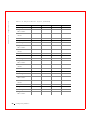
SCSI Drive States
The SCSI drive states are listed in Table 2-3.
Ta b l e 2 - 3 . S C S I D r i v e S t a t e s
State
Description
Online
The drive is working normally and is a part of a configured
logical drive.
(ONLIN)
I n tr o d uc t io n t o RA I D
39
w w w. d e l l . c o m | s u p p o r t . d e l l . c o m
Ta b l e 2 - 3 . S C S I D r i v e S t a t e s (continued)
State
Description
Ready
The drive is functioning normally but is not part of a
configured logical drive and is not designated as a hot spare.
(READY)
Hot Spare
(HOTSP)
The drive is powered up and ready for use as a spare in case an
online drive fails.
Fail (FAIL)
A fault has occurred in the drive, placing it out of service.
Rebuild (REB)
The drive is being rebuilt with data from a failed drive.
Logical Drive States
The logical drive states are listed in Table 2-4.
Ta b l e 2 - 4 . L o g i c a l D r i v e S t a t e s
State
Description
Optimal
The drive operating condition is good. All configured drives are
online.
Degraded
The drive operating condition is not optimal. One of the
configured drives has failed or is offline.
Failed
The drive has failed.
Offline
The drive is not available to the RAID controller.
Enclosure Management
Enclosure management is the intelligent monitoring of the disk subsystem
by software and/or hardware. The disk subsystem can be part of the host
computer or separate from it. Enclosure management helps you stay
informed of events in the disk subsystem, such as a drive or power supply
failure. Enclosure management increases the fault tolerance of the disk
subsystem.
40
In t ro duc ti o n to RAI D
SECTION 3
RAID Levels
Overview
Selecting a RAID Level
RAID 0
RAID 1
RAID 5
RAID 10
RAID 50
w w w. d e l l . c o m | s u p p o r t . d e l l . c o m
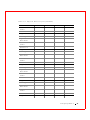
Overview
There are six official RAID levels (RAID 0 through RAID 5.) PERC 3
supports RAID levels 0, 1, 5, 10, and 50. The RAID levels that PERC 3
supports are shown in Table 3-1.
Ta b l e 3 - 1 . R A I D L e v e l s
RAID
Level
Type
0
Standard
1
Standard
5
Standard
1+0
Combination of RAID 0 and RAID 1
5+0
Combination of RAID 0 and RAID 5
PERC 3 also supports independent drives (configured as RAID 0.)
Selecting a RAID Level
To ensure the best performance, you should select the optimal RAID level
when you create a system drive. The optimal RAID level for your disk array
depends on a number of factors:
42
RAI D L e ve ls
•
The number of physical drives in the disk array
•
The capacity of the physical drives in the array
•
The need for data redundancy
•
The disk performance requirements
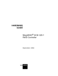
RAID 0
RAID 0 provides disk striping across all drives in the RAID subsystem. RAID
0 does not provide any data redundancy, but does offer the best
performance of any RAID level. RAID 0 breaks up data into smaller blocks
and then writes a block to each drive in the array. The size of each block is
determined by the stripe size parameter, set during the creation of the RAID
set. RAID 0 offers high bandwidth.
By breaking up a large file into smaller blocks, PERC 3 can use several drives
to read or write the file faster. RAID 0 involves no parity calculations to
complicate the write operation. This makes RAID 0 ideal for applications
that require high bandwidth but do not require fault tolerance. RAID 0 is
also used to denote an “independent” or single drive.
Table 3-2 provides an overview of RAID 0.
Ta b l e 3 - 2 . R A I D 0 O v e r v i e w
Uses
RAID 0 provides high data throughput, especially for
large files. Any environment that does not require
fault tolerance.
Strong Points
Provides increased data throughput for large files. No
capacity loss penalty for parity.
Weak Points
Does not provide fault tolerance. All data lost if any
drive fails.
Drives
1 to 32
RAI D L e v el s
43
w w w. d e l l . c o m | s u p p o r t . d e l l . c o m
Figure 3-1 displays an example of a RAID 0 array.
Figure 3-1. RAID 0 Array
Segment 1
Segment 5
Segment 7
44
RAI D L e ve ls
Segment 2
Segment 6
Segment 10
Segment 3
Segment 7
Segment 11
Segment 4
Segment 8
Segment 12
RAID 1
In RAID 1, the RAID controller duplicates all data from one drive to a
second drive. RAID 1 provides complete data redundancy, but at the cost of
doubling the required data storage capacity, as shown in Figure 3-2. Table 33 provides an overview of RAID 1.
Ta b l e 3 - 3 . R A I D 1 O v e r v i e w
Uses
Use RAID 1 for small databases or any other
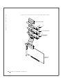
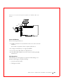
environment that requires fault tolerance but small
capacity.
Strong Points
RAID 1 provides complete data redundancy. RAID 1 is
ideal for any application that requires fault tolerance
and minimal capacity.
Weak Points
RAID 1 requires twice as many disk drives.
Performance is impaired during drive rebuilds.
Drives
2
RAI D L e v el s
45
w w w. d e l l . c o m | s u p p o r t . d e l l . c o m
Figure 3-2. RAID 1 Array
Segment 1
Segment 2
Segment 3
Segment 4
Segment 1 Duplicated
Segment 2 Duplicated
Segment 3 Duplicated
Segment 4 Duplicated
RAID 5
RAID 5 includes disk striping at the block level and parity. In RAID 5, the
parity information is written to several drives. RAID 5 is best suited for
networks that perform a lot of small input/output (I/O) transactions
simultaneously.
RAID 5 addresses the bottleneck issue for random I/O operations. Because
each drive contains both data and parity numerous writes can take place
concurrently. In addition, robust caching algorithms and hardware based
exclusive-or assist make RAID 5 performance exceptional in many different
environments.
Table 3-4 provides an overview of RAID 5.
46
RAI D L e ve ls
Ta b l e 3 - 4 . R A I D 5 O v e r v i e w
Uses
RAID 5 provides high data throughput, especially for
large files. Use RAID 5 for transaction processing
applications because each drive can read and write
independently. If a drive fails, PERC 3 uses the parity
drive to recreate all missing information. Use also for
office automation and online customer service that
requires fault tolerance. Use for any application that
has high read request rates but low write request rates.
Strong Points
Provides data redundancy and good performance in
most environments
Weak Points
Disk drive performance will be reduced if a drive is
being rebuilt. Environments with few processes do not
perform as well because the RAID overhead is not
offset by the performance gains in handling
simultaneous processes.
Drives
3 to 32
RAI D L e v el s
47
w w w. d e l l . c o m | s u p p o r t . d e l l . c o m
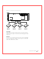
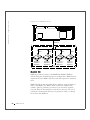
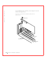
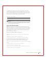
Figure 3-3 displays an example of a RAID 5 array.
Figure 3-3. RAID 5 Array
Data Flow
Disk 1
Segment 1
Segment 7
Parity (9–12)
Disk 2
Segment 2
Segment 8
Disk 3
Segment 3
Segment 9
Parity (5–8)
Disk 4
Segment 4
Segment 10
Disk 5
Segment 5
Segment 11
Parity (1–4)
Disk 6
Segment 6
Segment 12
Note: Parity is distributed across drives in the array.
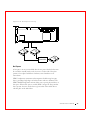
RAID 10
RAID 10 is a combination of RAID 0 and RAID 1. RAID 10 has mirrored
drives. RAID 10 breaks up data into smaller blocks, and then mirrors the
blocks of data to each RAID 1 RAID set. Each RAID 1 RAID set then
duplicates its data to its other drive. The size of each block is determined by
the stripe size parameter, which is set during the creation of the RAID set.
RAID 10 can sustain one to four drive failures while maintaining data
integrity if each failed disk is in a different RAID 1 array.
Table 3-5 provides an overview of RAID 10.
48
RAI D L e ve ls
Ta b l e 3 - 5 . R A I D 1 0 O v e r v i e w
Uses
RAID 10 works best for data storage that needs 100%
redundancy of mirrored arrays and that also needs the
enhanced I/O performance of RAID 0 (striped arrays.)
RAID 10 works well for medium-sized databases or
any environment that requires a higher degree of fault
tolerance and moderate to medium capacity.
Strong Points
RAID 10 provides both high data transfer rates and
complete data redundancy.
Weak Points
RAID 10 requires twice as many drives as all other
RAID levels except RAID 1.
Drives
2n, where n is greater than 1. The maximum number
of drives is 16.
RAI D L e v el s
49
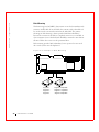
w w w. d e l l . c o m | s u p p o r t . d e l l . c o m
Figure 3-4. RAID 10 Array
Data Flow
RAID 1
Disk 1
Segment 1
Segment 3
Segment 5
RAID 1
Disk 2
Disk 3
Segment 1
Segment 3
Segment 5
Segment 2
Segment 4
Segment 6
D
Disk 4
Segment 2
Segment 4
Segment 6
RAID 0
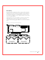
RAID 50
RAID 50 provides the features of both RAID 0 and RAID 5. RAID 50
includes both parity and disk striping across multiple drives. RAID 50 is best
implemented on two RAID 5 disk arrays with data striped across both disk
arrays.
RAID 50 breaks up data into smaller blocks, and then stripes the blocks of
data to each RAID 5 array. RAID 5 breaks up data into smaller blocks,
calculates parity by performing an exclusive-or on the blocks, and then
writes the blocks of data and parity to each drive in the array. The size of
each block is determined by the stripe size parameter, which is set during
the creation of the RAID set.
50
RAI D L e ve ls
RAID 50 can sustain one to four drive failures while maintaining data
integrity if each failed disk is in a different RAID 5 array.
Table 3-6 provides an overview of RAID 50.
Ta b l e 3 - 6 . R A I D 5 0 O v e r v i e w
Uses
RAID 50 works best when used with data that requires
high reliability, high request rates, and high data
transfer and medium to large capacity.
Strong Points
RAID 50 provides high data throughput, data
redundancy, and very good performance.
Weak Points
Requires 2 to 4 times as many parity drives as RAID 5.
Drives
6 to 256 (Eight arrays x 32 stripes = 256 drives)
RAI D L e v el s
51
w w w. d e l l . c o m | s u p p o r t . d e l l . c o m
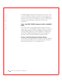
Figure 3-5 displays an example of a RAID 50 array.
Figure 3-5. RAID 50 Array
Data Flow
RAID 5
Disk 1
Segment 1
Segment 6
Parity (9-10)
Disk 2
Segment 2
Parity (5-6)
Segment 9
RAID 5
Disk 4
Disk 3
Parity (1-2)
Segment 5
Segment 10
Segment 3
Segment 8
Parity (11-12)
RAID 0
52
RAI D L e ve ls
Disk 5
Segment 4
Parity (7-8)
Segment 11
Disk 6
Parity (3-4)
Segment 7
Segment 12
SECTION 4
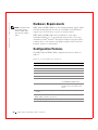
P E R C 3 / S C Fe a t u r e s
Hardware Requirements
Configuration Features
Hardware Architecture Features
Array Performance Features
PERC 3/SC Fault Tolerance Features
Software Utilities
Operating System Software Drivers
PERC 3/SC Specifications
w w w. d e l l . c o m | s u p p o r t . d e l l . c o m
Hardware Requirements
PERC 3/SC has one SCSI) channel that supports 160M and Wide SCSI at
data transfer rates up to 160 MB/s. The SCSI channel supports up to 15
Wide devices or up to seven narrow devices.
PERC 3/SC can be installed in a Dell™ PowerEdge™ computer with a
motherboard that has 5 V, 32- or 64-bit PCI expansion slots. The computer
should have an Intel® Pentium® II or higher central processing unit (CPU),
a diskette drive, a color monitor and video graphics adapter (VGA) card, and
a keyboard. A mouse is recommended.
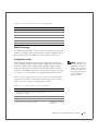
Configuration Features
Table 4-1 lists the configuration features for the PERC 3/SC controller.
Ta b l e 4 - 1 . C o n f i g u r a t i o n Fe a t u r e s
54
PERC 3/ SC Feat ures
Specification
Feature
RAID levels
0, 1, 5, 10, and 50.
SCSI channels
1
Maximum number of drives per
channel
15
Array interface to host
PCI 2.2
Drive interface
Wide 160M
Cache memory size
32 MB
Cache function
Write-back, write-through, adaptive
read-ahead, non-read-ahead, readahead
Multiple logical drives/arrays per
controller
Up to 40 logical drives per controller
Maximum number of PERC 3/SC
controller per system
Contact your Dell representative.
Online capacity expansion
Yes
Dedicated and pool hot spare
Yes
Flashable firmware
Yes
Hot swap devices supported
Yes
Ta b l e 4 - 1 . C o n f i g u r a t i o n Fe a t u r e s (continued)
Specification
Feature
Non-disk devices supported
No
Mixed capacity hard disk drives
Yes
Number of 16-bit internal connectors
1
SMART Technology
The PERC 3/SC self-monitoring analysis and reporting technology
(SMART) detects predictable drive failures. SMART monitors the internal
performance of all motors, heads, and drive electronics.
Configuration on Disk Configuration
Configuration on Disk (drive roaming) saves configuration information
both in non-volatile random access memory (NVRAM) on PERC 3/SC and
on the disk drives attached to PERC 3/SC. If the controller is replaced, the
new controller detects the actual RAID configuration from the
configuration information on the drives. This maintains the integrity of the
data on each drive, even if the drives have changed their target ID.
Drive roaming is supported across channels on the same controller. Drive
roaming across channels is not supported when cluster mode is enabled.
Table 4-2 lists the Configuration on Disk features for the PERC 3/SC
controller.
NOTE: Configuration on
Disk does not work if you
change both the adapter,
and the SCSI connectors
to different connectors on
the new adapter. It will
work only if you make one
change at a time.
Ta b l e 4 - 2 . C o n f i g u r a t i o n o n D i s k Fe a t u r e s
Specification
Feature
Support for hard disk drives with
capacities of more than 8 gigabytes (GB)
Yes
Online RAID level migration
Yes
RAID remapping
Yes
No reboot necessary after expansion
Yes (only if virtual sizing is
enabled)
More than 200 qtags per array
Yes
Hardware clustering support on the board
Yes
PE RC 3/SC Fe atures
55
w w w. d e l l . c o m | s u p p o r t . d e l l . c o m
Ta b l e 4 - 2 . C o n f i g u r a t i o n o n D i s k Fe a t u r e s (continued)
Specification
Feature
User-specified rebuild rate
Yes
Hardware Architecture Features
The PERC 3/SC hardware architecture features are shown in Table 4-3.
Ta b l e 4 - 3 . H a r d w a r e A r c h i t e c t u r e Fe a t u r e s
Specification
Feature
Processor
Intel i960RM 100MHz
SCSI controller(s)
One QLogic® 10160 Single SCSI
controller
Size of flash ROM
1 MB
Amount of NVRAM
32 KB
Hardware-exclusive OR (XOR)
assistance
Yes
Direct I/O
Yes
SCSI bus termination
Active, single-ended or low voltage
differential (LVD)
Double-sided dual in-line memory
modules (DIMMs)
Yes
Auxiliary TermPWR source
No
Direct I/O bandwidth
132 MB/s
Array Performance Features
The PERC 3/SC array performance features are shown in Table 4-4.
Ta b l e 4 - 4 . A r r a y P e r f o r m a n c e Fe a t u r e s
56
PERC 3/ SC Feat ures
Specification
Feature
Host data transfer rate
132 MB/s
Drive data transfer rate
160 MB/s
Ta b l e 4 - 4 . A r r a y P e r f o r m a n c e Fe a t u r e s (continued)
Specification
Feature
Maximum scatter/gathers
26 elements
Maximum size of I/O requests
6.4 MB in 64 KB stripes
Maximum queue tags per drive
As many as the drive can accept.
Stripe sizes
2 KB, 4 KB, 8 KB, 16 KB, 32 KB,
64 KB, or 128 KB
Maximum number of concurrent
commands
255
Support for multiple initiators
Yes
PERC 3/SC Fault Tolerance Features
The PERC 3/SC fault tolerance features are shown in Table 4-5.
Ta b l e 4 - 5 . P E R C 3 / S C Fa u l t To l e r a n c e Fe a t u r e s
Specification
Feature
Support for SMART
Yes
Drive failure detection
Automatic
Drive rebuild using hot spares
Automatic
Manual replacement of drives without system
shutdown
Yes
Parity generation and checking
Yes
Software Utilities
The PERC 3/SC software utilities are shown in Table 4-6.
Ta b l e 4 - 6 . S o f t w a r e U t i l i t i e s Fe a t u r e s
Specification
Feature
Graphical user interface
Yes
Management utility
Yes
PE RC 3/SC Fe atures
57
w w w. d e l l . c o m | s u p p o r t . d e l l . c o m
Ta b l e 4 - 6 . S o f t w a r e U t i l i t i e s Fe a t u r e s (continued)
Specification
Feature
Bootup configuration using the PERC BIOS
configuration utility (Ctrl–M)
Yes
Online read, write, and cache policy switching
Yes
Intranet support
Yes
Operating System Software Drivers
Operating System Drivers
PERC 3/SC includes a disk operating system (DOS) software configuration
utility and drivers for Microsoft® Windows NT® V4.0, Windows® 2000,
Novell® NetWare® 5.x, 6.x, and Red Hat Linux 7.x.
PERC 3/SC Specifications
The PERC 3/SC specifications are shown in Table 4-7.
Ta b l e 4 - 7 . P E R C 3 / S C S p e c i f i c a t i o n s
58
PERC 3/ SC Feat ures
Parameter
Specification
Card size
Half-length PCI adapter card size (6.875" X 4.2")
Processor
Intel i960RM™ 64-bit RISC processor @
100 MHz
Bus type
PCI 2.2
PCI controller
Intel i960RM
Bus data transfer rate
Up to 132 MB/s at 32/33 MHz
Basic input/output system
(BIOS)
PERC 3/SC BIOS
Cache configuration
32 MB
Firmware
1 MB × 8 flash ROM
Non-volatile random access
memory (RAM)
32 KB × 8 for storing RAID configuration
Operating voltage
5 V, 3.3 V
Ta b l e 4 - 7 . P E R C 3 / S C S p e c i f i c a t i o n s (continued)
Parameter
Specification
SCSI controller
One SCSI controller for 160M and Wide support
SCSI data transfer rate
Up to 160 MB/s per channel
SCSI bus
Low-voltage differential (LVD) or single-ended
SCSI termination
Active
Termination disable
Automatic through cable and device detection
Devices per SCSI channel
Up to 15 wide or seven narrow SCSI devices
SCSI device types
Synchronous or asynchronous
RAID levels supported
0, 1, 5, 10, and 50
SCSI connectors
One 68-pin internal high-density connectors for
16-bit SCSI devices. One ultra-high density 68pin external connectors for 160M and Wide
SCSI.
Serial port
3-pin RS232C-compatible connector (for
manufacturing use only)
PCI Bridge/CPU
PERC 3/SC uses the Intel i960RM PCI bridge with an embedded i960RM
RISC processor running at 100 MHz. The RM bridge handles data transfers
between the primary (host) PCI bus, the secondary PCI bus, cache memory,
and the SCSI bus. The DMA controller supports chaining and unaligned
data transfers. The embedded i960JT CPU directs all controller functions,
including command processing, SCSI bus transfers, RAID processing, drive
rebuilding, cache management, and error recovery.
Cache Memory
32 MB of PERC 3/SC cache memory resides in a memory bank. PERC 3/SC
supports write-through or write-back caching, selectable for each logical
drive. To improve performance in sequential disk accesses, the PERC 3/SC
controller uses read-ahead caching by default. You can disable read-ahead
caching.
PE RC 3/SC Fe atures
59
w w w. d e l l . c o m | s u p p o r t . d e l l . c o m
PERC 3/SC BIOS
The BIOS resides on a 1 MB × 8 flash ROM for easy upgrade. The PERC
3/SC BIOS supports INT 13h calls to boot DOS without special software or
device drivers. The PERC 3/SC BIOS provides an extensive setup utility
that can be accessed by pressing <Ctrl> <M> at BIOS initialization. The
PERC 3/SC BIOS Configuration Utility is described in Chapter 11.
Onboard Speaker
The PERC 3/SC controller has an onboard tone generator for audible
warnings when system errors occur. Audible warnings can be generated
through this speaker. The audible warnings are listed in Chapter 13.
Serial Port
PERC 3/SC includes a 3-pin RS232C-compatible serial port connector. This
is for manufacturing use only.
SCSI Bus
PERC 3/SC has one Wide 160M SCSI channels that support both LVD and
single-ended devices with active termination. Synchronous and
asynchronous devices are supported. PERC 3/SC provides automatic
termination disable via cable detection. The SCSI channel supports up to
15 wide or seven non-wide SCSI devices at speeds up to 160 MB/s.
SCSI Connectors
PERC 3/SC has two types of SCSI connectors:
•
One 68-pin high density internal connector
•
One 68-pin external ultra-high-density connector
Only one connector type can be used for the SCSI channel at any one time.
SCSI Termination
PERC 3/SC uses active termination on the SCSI bus conforming to SCSI-2
and SCSI-3 specifications. Termination enable/disable is automatic through
cable detection.
60
PERC 3/ SC Feat ures
SCSI Firmware
The PERC 3/SC firmware handles all RAID and SCSI command processing
and also supports the features shown in Table 4-8.
Ta b l e 4 - 8 . S C S I F i r m w a r e S u p p o r t
Feature
Description
Disconnect/
reconnect
Optimizes SCSI bus utilization
Tagged command
queuing
Multiple tags to improve random access
Scatter/gather
Single command can transfer data to and from different
memory locations
Multi-threading
Up to 255 simultaneous commands with elevator sorting
and concatenation of requests per SCSI channel
Stripe size
Variable for all logical drives: 2 KB, 4 KB, 8 KB, 16 KB,
32 KB, 64 KB, or 128 KB.
Rebuild
Multiple rebuilds and consistency checks with userdefinable priority
RAID Management
RAID management is provided by software utilities that manage and
configure the RAID system and PERC 3/SC, create and manage multiple
disk arrays, control and monitor multiple RAID servers, provide error
statistics logging, and provide online maintenance. They include:
•
PERC 3 BIOS Configuration utility (Ctrl-M)
•
Dell Manager
•
WebBIOS Configuration Utility
•
Dell™ OpenManage™ Array Manager
PERC 3 BIOS Configuration Utility
You can use the PERC 3 BIOS Configuration Utility to configure and
maintain RAID arrays, format disk drives, and manage the RAID system. It
is independent of any operating system. See Chapter 11 "PERC 3 BIOS
Configuration Utility" for additional information.
PE RC 3/SC Fe atures
61
w w w. d e l l . c o m | s u p p o r t . d e l l . c o m
Dell Manager
Dell Manager is a character-based, non-GUI utility that changes policies
and parameters, and monitors RAID systems. Dell Manager runs under
Novell NetWare 5.x, 6.x, and Red Hat Linux 7.x. See Chapter 12 "Dell
Manager" for additional information.
WebBIOS Configuration Utility
WebBIOS is used to configure and manage a RAID system using an HTML
interface. See the WebBIOS Configuration Utility Guide for more
information.
Dell OpenManage Array Manager
Dell OpenManage Array Manager is used to configure and manage a storage
system that is connected to a server, while the server is active and continues
to handle requests. Array Manager runs under NetWare, Windows NT, and
Windows 2000. Refer to Dell documentation on the Dell web site at
support.dell.com for more information.
62
PERC 3/ SC Feat ures
SECTION 5
PERC 3/DC and PERC
3 / D C L Fe a t u r e s
Hardware Requirements
Configuration Features
Hardware Architecture Features
Array Performance Features
Fault Tolerance Features
Software Utilities
Operating System Software Drivers
PERC 3/DC and PERC 3/DCL Specifications
w w w. d e l l . c o m | s u p p o r t . d e l l . c o m
Hardware Requirements
NOTE: The PERC 3/DC
has a battery option,
while the PERC 3/DCL
does not have a battery
option.
PERC 3/DC and PERC 3/DCL have two SCSI channels that support 160M
and Wide SCSI at data transfer rates up to 160 MB/s. The SCSI channel
supports up to 15 Wide devices or up to seven narrow devices.
PERC 3/DC and PERC 3/DCL can be installed in a system with a
motherboard that has 5 V, 32- or 64-bit PCI expansion slots. The system
should have an Intel® Pentium® II or higher central processing unit (CPU),
a diskette drive, a color monitor, video graphics adapter (VGA) card, and a
keyboard. A mouse is recommended.
Configuration Features
The PERC 3/DC and PERC 3/DCL configuration features are shown in
Table 5-1.
Ta b l e 5 - 1 . C o n f i g u r a t i o n Fe a t u r e s
Specification
Feature
RAID levels
0, 1, 5, 10, and 50
SCSI channels
2
Maximum number of drives per channel
15
Array interface to host
PCI 2.2
Drive interface
Wide 160M
Cache memory size
64 MB (PERC 3/DCL)
128 MB DIMM (PERC 3/DC)
64
Cache function
Write-back, write-through, adaptive
read-ahead, non read-ahead, readahead
Multiple logical drives/arrays per
controller
Up to 40 logical drives per controller
Maximum number of PERC 3/DC and
PERC 3/DCL controllers per system
Contact your Dell™ representative.
Online capacity expansion
Yes
Dedicated and pool hot spare
Yes
PERC 3/ DC and PE RC 3 /DCL Fe atures
Ta b l e 5 - 1 . C o n f i g u r a t i o n Fe a t u r e s (continued)
Specification
Feature
Flashable firmware
Yes
Hot swap devices supported
Yes
Non-disk devices supported
No
Mixed capacity hard disk drives
Yes
Number of 16-bit internal connectors
2
Cluster support
Yes (PERC 3/DC only)
SMART Technology
The PERC 3/DC and PERC 3/DCL self-monitoring analysis and reporting
technology (SMART) detects predictable drive failures. SMART monitors
the internal performance of all motors, heads, and drive electronics.
Configuration on Disk
Configuration on Disk (drive roaming) saves configuration information
both in NVRAM on PERC 3/DC and PERC 3/DCL and on the disk drives
attached to PERC 3/DC and PERC 3/DCL. If PERC 3/DC and PERC
3/DCL are replaced, the new PERC 3/DC and PERC 3/DCL controllers
detect the actual RAID configuration, maintaining the integrity of the data
on each drive, even if the drives have changed channel and/or target ID.
Drive roaming is supported across channels on the same controller. Drive
roaming across channels is not supported when cluster mode is enabled.
Table 5-2 shows the features for Configuration on Disk.
NOTE: Configuration on
Disk does not work if you
change both the adapter,
and the SCSI connectors
to different connectors on
the new adapter. It works
only if you make one
change at a time.
Ta b l e 5 - 2 . C o n f i g u r a t i o n o n D i s k Fe a t u r e s
Specification
Feature
Support for hard disk drives with capacities of more
than 8 gigabytes (GB)
Yes
Online RAID level migration
Yes
RAID remapping
Yes
No reboot necessary after expansion
Yes (Only if virtual sizing
is enabled.)
PE RC 3/ DC and PE RC 3/DC L Fe atures
65
w w w. d e l l . c o m | s u p p o r t . d e l l . c o m
Ta b l e 5 - 2 . C o n f i g u r a t i o n o n D i s k Fe a t u r e s (continued)
Specification
Feature
More than 200 qtags per array
Yes
Hardware clustering support on the board
Yes
User-specified rebuild rate
Yes
Hardware Architecture Features
Table 5-3 displays the PERC 3/DC and PERC 3/DCL hardware architecture
features.
Ta b l e 5 - 3 . H a r d w a r e A r c h i t e c t u r e Fe a t u r e s
66
Specification
Feature
Processor
Intel i960RN 100MHz
SCSI controller(s)
One QLogic® 12160 Dual SCSI
controller
Size of flash ROM
1 MB
Amount of non-volatile random access
memory (NVRAM)
32 KB
Hardware-exclusive OR (XOR)
assistance
Yes
Direct input/output (I/O)
Yes
SCSI bus termination
Active, single-ended or low voltage
differential (LVD)
Double-sided dual in-line memory
modules (DIMMs)
Yes
Auxiliary TermPWR source
No
Direct I/O bandwidth
533 MB/s (greater than 200 MB/s
sustained)
PERC 3/ DC and PE RC 3 /DCL Fe atures
Array Performance Features
Table 5-4 displays the PERC 3/DC and PERC 3/DCL array performance
features.
Ta b l e 5 - 4 . A r r a y P e r f o r m a n c e Fe a t u r e s
Specification
Feature
Host data transfer rate
533 MB/s
Drive data transfer rate
160 MB/s
Maximum scatter/gathers
26 elements
Maximum size of I/O requests
6.4 MB in 64 KB stripes
Maximum queue tags per drive
As many as the drive can accept.
Stripe sizes
2 KB, 4 KB, 8 KB, 16 KB, 32 KB,
64 KB, or 128 KB
Maximum number of concurrent
commands
255
Support for multiple initiations
Yes
Fault Tolerance Features
Table 5-5 lists the fault tolerance features.
Ta b l e 5 - 5 . Fa u l t To l e r a n c e Fe a t u r e s
Specification
Feature
Support for SMART
Yes
Optional battery backup for cache memory
Yes. Up to 72 hours data
retention.
Drive failure detection
Automatic
Drive rebuild using hot spares
Automatic
Manual replacement of hard drives without system
shutdown
Yes
Parity generation and checking
Yes
PE RC 3/ DC and PE RC 3/DC L Fe atures
67
w w w. d e l l . c o m | s u p p o r t . d e l l . c o m
Software Utilities
Table 5-6 lists the software utilities.
Ta b l e 5 - 6 . S o f t w a r e U t i l i t i e s
Specification
Feature
Graphical user interface (GUI)
Yes
Management utility
Yes
Bootup configuration using BIOS Configuration Utility
(Ctrl–M)
Yes
Online read, write, and cache policy switching
Yes
Intranet support
Yes
Operating System Software Drivers
PERC 3/DC and PERC 3/DCL include a Disk Operating System (DOS)
software configuration utility and drivers for Microsoft® Windows NT®
V4.0, Windows® 2000, Novell® NetWare® 5.x, 6.x, and Red Hat Linux 7.x.
PERC 3/DC and PERC 3/DCL
Specifications
Table 5-7 lists the PERC 3/DC and PERC 3/DCL specifications.
Ta b l e 5 - 7 . P E R C 3 / D C a n d P E R C 3 / D C L S p e c i f i c a t i o n s
Parameter
68
Specification
Card size
Half-length PCI card size (6.875" X 4.2").
Processor
Intel i960RN™ 64-bit RISC processor @ 100 MHz
Bus type
PCI 2.2
PCI controller
Intel i960RN
Bus data transfer rate
Up to 533 MB/s at 64/66 MHz
Basic input/output system
(BIOS)
PERC 3/DC and PERC 3/DCL BIOS
PERC 3/ DC and PE RC 3 /DCL Fe atures
Ta b l e 5 - 7 . P E R C 3 / D C a n d P E R C 3 / D C L S p e c i f i c a t i o n s
Parameter
Specification
Cache configuration
64 MB or 128 MB DIMM
Firmware
1 MB × 8 flash ROM
Nonvolatile random access
memory (RAM)
32 KB × 8 for storing RAID configuration
Operating voltage
5 V, 3.3 V
SCSI controller
Two SCSI controllers for 160M and Wide support.
SCSI data transfer rate
Up to 160 MB/s per channel
SCSI bus
LVD or single-ended
SCSI termination
Active
Termination disable
Automatic through cable and device detection
Devices per SCSI channel
Up to 15 wide or seven narrow SCSI devices.
SCSI device types
Synchronous or asynchronous.
RAID levels supported
0, 1, 5, 10, and 50
SCSI connectors
Two 68-pin internal high-density connectors for 16bit SCSI devices. Two ultra-high density 68-pin
external connectors for 160M and Wide SCSI.
Serial port
3-pin RS232C-compatible connector (for
manufacturing use only)
PCI Bridge/CPU
Both PERC 3/DC and PERC 3/DCL use the Intel i960RN PCI bridge with
an embedded i960RN RISC processor running at 100 MHz. The RN bridge
handles data transfers between the primary (host) PCI bus, the secondary
PCI bus, cache memory, and the SCSI bus. The DMA controller supports
chaining and unaligned data transfers. The embedded i960JN CPU directs
all controller functions, including command processing, SCSI bus transfers,
RAID processing, drive rebuilding, cache management, and error recovery.
PE RC 3/ DC and PE RC 3/DC L Fe atures
69
w w w. d e l l . c o m | s u p p o r t . d e l l . c o m
Cache Memory
Either 64 MB or 128 MB of PERC 3/DC and PERC 3/DCL cache memory
reside in a memory bank that uses a 64 MB or 128 MB SDRAM DIMM.
PERC 3/DC and PERC 3/DCL support write-through or write-back
caching, selectable for each logical drive. To improve performance in
sequential disk accesses, the PERC 3/DC and PERC 3/DCL controllers use
read-ahead caching by default. You can disable read-ahead caching.
PERC 3/DC and PERC 3/DCL BIOS
The BIOS resides on a 1 MB × 8 flash ROM for easy upgrade. The PERC
3/DC and PERC 3/DCL BIOS supports INT 13h calls to boot DOS without
special software or device drivers. The PERC 3/DC and PERC 3/DCL BIOS
provides an extensive setup utility that can be accessed by pressing <Ctrl>
<M> at BIOS initialization. PERC 3/DC and PERC 3/DCL BIOS
Configuration utility is described in Chapter 11 "PERC 3 BIOS
Configuration Utility."
Onboard Speaker
The PERC 3/DC and PERC 3/DCL controller has an onboard tone
generator for audible warnings when system errors occur. Audible warnings
can be generated through this speaker. The audible warnings are listed in
Chapter 13 "Troubleshooting."
Serial Port
PERC 3/DC and PERC 3/DCL includes a 3-pin RS232C-compatible serial
port connector. This is for manufacturing use only.
SCSI Bus
The PERC 3/DC and PERC 3/DCL controller has four Wide 160M SCSI
channels that support both LVD and single-ended devices with active
termination. Synchronous and asynchronous devices are supported. PERC
3/DC and PERC 3/DCL provides automatic termination disable via cable
detection. The SCSI channel supports up to 15 wide or seven non-wide
SCSI devices at speeds up to 160 MB/s.
70
PERC 3/ DC and PE RC 3 /DCL Fe atures
SCSI Connectors
The PERC 3/DC and PERC 3/DCL adapter has two types of SCSI
connectors:
•
Two 68-pin high density internal connectors
•
Two 68-pin external ultra-high-density connectors
Only one connector type can be used for the SCSI channel at any one time.
SCSI Termination
PERC 3/DC and PERC 3/DCL uses active termination on the SCSI bus
conforming to SCSI-2 and SCSI-3 specifications. Termination
enable/disable is automatic through cable detection.
SCSI Firmware
The PERC 3/DC and PERC 3/DCL firmware handles all RAID and SCSI
command processing and supports the feature listed in Table 5-8.
Ta b l e 5 - 8 . S C S I F i r m w a r e
Feature
Description
Disconnect/
reconnect
Optimizes SCSI bus seek.
Tagged command
queuing
Multiple tags to improve random access
Scatter/gather
A single command can transfer data to and from different
memory locations.
Multi-threading
Up to 255 simultaneous commands with elevator sorting
and concatenation of requests per SCSI channel
Stripe size
Variable for all logical drives: 2 KB, 4 KB, 8 KB, 16 KB,
32 KB, 64 KB, or 128 KB
Rebuild
Multiple rebuilds and consistency checks with userdefinable priority
PE RC 3/ DC and PE RC 3/DC L Fe atures
71
w w w. d e l l . c o m | s u p p o r t . d e l l . c o m
RAID Management
RAID management is provided by software utilities that manage and
configure the RAID system and PERC 3/DC and PERC 3/DCL, create and
manage multiple disk arrays, control and monitor multiple RAID servers,
provide error statistics logging, and provide online maintenance. The
utilities are:
•
PERC 3 BIOS Configuration utility (Ctrl-M)
•
Dell Manager
•
WebBIOS Configuration Utility
•
Dell OpenManage™ Array Manager
PERC 3 BIOS Configuration Utility
You can use the PERC 3 BIOS Configuration Utility to configure and
maintain RAID arrays, format disk drives, and manage the RAID system. It
is independent of any operating system. See Chapter 11 "PERC 3 BIOS
Configuration Utility" for additional information.
Dell Manager
Dell Manager is a character-based, non-GUI utility that changes policies,
and parameters, and monitors RAID systems. Dell Manager runs under
Novell NetWare 5.x, 6.x, and Red Hat Linux 7.x. See Chapter 12 "Dell
Manager" for additional information.
WebBIOS Configuration Utility
WebBIOS is used to configure and manage a RAID system using an HTML
interface. See the WebBIOS Configuration Utility Guide for more
information.
Dell OpenManage Array Manager
Dell OpenManage Array Manager is used to configure and manage a storage
system that is connected to a server, while the server is active and continues
to handle requests. Array Manager runs under NetWare, Windows NT, and
Windows 2000. Refer to Dell documentation on the Dell web site at
support.dell.com for more information.
72
PERC 3/ DC and PE RC 3 /DCL Fe atures
SECTION 6
P E R C 3 / Q C Fe a t u r e s
Hardware Requirements
Configuration Features
Hardware Architecture Features
Array Performance Features
Fault Tolerance Features
Software Utilities
Operating System Software Drivers
PERC 3/QC Specifications
w w w. d e l l . c o m | s u p p o r t . d e l l . c o m
Hardware Requirements
PERC 3/QC is a high-performance intelligent peripheral component
interconnect (PCI)-to-SCSI host adapter with RAID control capabilities.
PERC 3/QC has four SCSI channels that support 160M and Wide SCSI at
data transfer rates up to 160 MB/s. Each SCSI channel supports up to 15
Wide devices or up to seven narrow devices.
PERC 3/QC can be installed in a system with a motherboard that has 5 V,
32- or 64-bit PCI expansion slots. The system should have an Intel®
Pentium® II or higher central processing unit (CPU), a diskette drive, a
color monitor, video graphics adapter (VGA) card, and a keyboard. A mouse
is recommended.
Configuration Features
Table 6-1 lists the PERC 3/QC configuration features.
Ta b l e 6 - 1 . C o n f i g u r a t i o n Fe a t u r e s
74
PERC 3/ QC Feat ures
Specification
Feature
RAID levels
0, 1, 5, 10, and 50
SCSI channels
4
Maximum number of drives per channel
15
Array interface to host
PCI 2.2
Drive interface
Wide 160M
Cache memory size
128 MB DIMM
Cache function
Write-back, write-through, adaptive
read-ahead, non read-ahead, readahead
Multiple logical drives/arrays per
controller
Up to 40 logical drives per controller
Maximum number of PERC 3/QC
controllers per system
Contact your Dell™ representative.
Online capacity expansion
Yes
Dedicated and pool hot spare
Yes
Flashable firmware
Yes
Ta b l e 6 - 1 . C o n f i g u r a t i o n Fe a t u r e s (continued)
Specification
Feature
Hot swap devices supported
Yes
Non-disk devices supported
No
Mixed-capacity hard drives
Yes
Number of 16-bit internal connectors
2
SMART Technology
The PERC 3/QC self-monitoring analysis and reporting technology
(SMART) detects predictable drive failures. SMART monitors the internal
performance of all motors, heads, and drive electronics.
NOTE: The PERC 3/QC
does not support
clustering.
Configuration on Disk
Configuration on Disk (drive roaming) saves configuration information
both in non-volatile random access memory (NVRAM) on PERC 3/QC and
on the disk drives attached to PERC 3/QC. If PERC 3/QC is replaced, the
new PERC 3/QC controller detects the actual RAID configuration,
maintaining the integrity of the data on each drive, even if the drives have
changed channel and/or target ID.
Drive roaming is supported across channels on the same controller. Drive
roaming across channels is not supported when cluster mode is enabled.
Table 6-2 lists the Configuration on Disk features.
NOTE: Configuration on
Disk does not work if you
change both the adapter,
and the SCSI connectors
to different connectors on
the new adapter. It works
only if you make one
change at a time.
Ta b l e 6 - 2 . C o n f i g u r a t i o n o n D i s k Fe a t u r e s
Specification
Feature
Support for hard drives with capacities of more
than 8 gigabytes (GB)
Yes
Online RAID level migration
Yes
RAID remapping
Yes
No reboot necessary after expansion
Yes (only if virtual sizing is
enabled)
More than 200 qtags per array
Yes
Hardware clustering support on the board
Yes
PE RC 3/QC Fe atures
75
w w w. d e l l . c o m | s u p p o r t . d e l l . c o m
Ta b l e 6 - 2 . C o n f i g u r a t i o n o n D i s k Fe a t u r e s (continued)
Specification
Feature
User-specified rebuild rate
Yes
Hardware Architecture Features
Table 6-3 lists the PERC 3/QC hardware architecture features.
Ta b l e 6 - 3 . H a r d w a r e A r c h i t e c t u r e Fe a t u r e s
Specification
Feature
Processor
Intel i960RN 100MHz
SCSI controller(s)
Two QLogic® 12160 dual SCSI
controller
Size of flash ROM
1 MB
Amount of NVRAM
32 KB
Hardware exclusive OR (XOR)
assistance
Yes
Direct input/output (I/O)
Yes
SCSI bus termination
Active, single-ended or low-voltage
differential (LVD)
Double-sided dual in-line memory
modules (DIMMs)
Yes
Auxiliary TermPWR source
No
Direct I/O bandwidth
533 MB/s (greater than 200 MB/s
sustained)
Array Performance Features
Table 6-4 lists the array performance features.
Ta b l e 6 - 4 . A r r a y P e r f o r m a n c e Fe a t u r e s
76
PERC 3/ QC Feat ures
Specification
Feature
Host data transfer rate
533 MB/s
Ta b l e 6 - 4 . A r r a y P e r f o r m a n c e Fe a t u r e s (continued)
Specification
Feature
Drive data transfer rate
160 MB/s
Maximum scatter/gathers
26 elements
Maximum size of I/O requests
6.4 MB in 64 KB stripes
Maximum queue tags per drive
As many as the drive can accept.
Stripe sizes
2 KB, 4 KB, 8 KB, 16 KB, 32 KB,
64 KB, or 128 KB
Maximum number of concurrent
commands
255
Support for multiple initiations
Yes
Fault Tolerance Features
The fault tolerance features are listed in Table 6-5.
Ta b l e 6 - 5 . Fa u l t To l e r a n c e Fe a t u r e s
Specification
Feature
Support for SMART
Yes
Optional battery backup for cache memory
Yes. Up to 72 hours data
retention.
Drive failure detection
Automatic
Drive rebuild using hot spares
Automatic
Manual replacement of drives without system
shutdown
Yes
Parity generation and checking
Yes
Software Utilities
The software utilities are listed in Table 6-6.
PE RC 3/QC Fe atures
77
w w w. d e l l . c o m | s u p p o r t . d e l l . c o m
Ta b l e 6 - 6 . S o f t w a r e U t i l i t i e s
Specification
Feature
Graphical user interface
Yes
Management utility
Yes
Bootup configuration using PERC BIOS configuration
utility (Ctrl–M)
Yes
Online read, write, and cache policy switching
Yes
Intranet support
Yes
Operating System Software Drivers
PERC 3/QC includes a DOS software configuration utility and drivers for
Microsoft® Windows NT® 4.0, Windows® 2000, Novell® NetWare® and
Red Hat Linux.
PERC 3/QC Specifications
The PERC 3/QC specifications are listed in Table 6-7.
Ta b l e 6 - 7 . P E R C 3 / Q C S p e c i f i c a t i o n s
78
PERC 3/ QC Feat ures
Parameter
Specification
Card size
12.3" x 4.2" (full length PCI)
Processor
Intel i960RN™ 64-bit RISC processor @ 100
MHz
Bus type
PCI 2.2
PCI controller
Intel i960RN
Bus data transfer rate
Up to 533 MB/s at 64/66 MHz
Basic input/output system
(BIOS)
PERC 3/QC BIOS
Cache configuration
64 MB or 128 MB DIMM
Firmware
1 MB × 8 flash ROM
Non-volatile random access
memory (RAM)
32 KB × 8 for storing RAID configuration
Ta b l e 6 - 7 . P E R C 3 / Q C S p e c i f i c a t i o n s (continued)
Parameter
Specification
Operating voltage
5 V, 3.3 V
SCSI controller
Four SCSI controllers for 160M and Wide
support.
SCSI data transfer rate
Up to 160 MB/s per channel
SCSI bus
LVD or single-ended
SCSI termination
Active
Termination disable
Automatic through cable and device detection
Devices per SCSI channel
Up to 15 wide or seven narrow SCSI devices.
SCSI device types
Synchronous or asynchronous.
RAID levels supported
0, 1, 5, 10, and 50
SCSI connectors
Two 68-pin internal high-density connectors for
16-bit SCSI devices. Four ultra-high density 68pin external connectors for 160M and Wide
SCSI.
Serial port
9-pin RS232C-compatible connector (for
manufacturing use only)
PCI Bridge/CPU
PERC 3/QC uses the Intel i960RN PCI bridge with an embedded i960RN
RISC processor running at 100 MHz. The RN bridge handles data transfers
between the primary (host) PCI bus, the secondary PCI bus, cache memory,
and the SCSI bus. The DMA controller supports chaining and unaligned
data transfers. The embedded i960JN CPU directs all controller functions,
including command processing, SCSI bus transfers, RAID processing, drive
rebuilding, cache management, and error recovery.
Cache Memory
128 MB of PERC 3/QC cache memory resides in a memory bank that uses a
64 MB or 128 MB SDRAM DIMM. PERC 3/QC supports write-through or
write-back caching, selectable for each logical drive. To improve
performance in sequential disk accesses, the PERC 3/QC controller uses
read-ahead caching by default. You can disable read-ahead caching.
PE RC 3/QC Fe atures
79
w w w. d e l l . c o m | s u p p o r t . d e l l . c o m
PERC 3/QC BIOS
The BIOS resides on a 1 MB × 8 flash ROM for easy upgrade. The PERC
3/QC BIOS supports INT 13h calls to boot DOS without special software or
device drivers. The PERC 3/QC BIOS provides an extensive setup utility
that can be accessed by pressing <Ctrl> <M> at BIOS initialization.
PERC 3 BIOS Configuration Utility is described in Chapter 11
"Troubleshooting."
Onboard Speaker
The PERC 3/QC controller has an onboard tone generator for audible
warnings when system errors occur. Audible warnings can be generated
through this speaker. The audible warnings are listed in Chapter 13.
Serial Port
PERC 3/QC includes a 9-pin RS232C-compatible serial port connector.
This is for manufacturing use only.
SCSI Bus
PERC 3/QC has four Wide 160M SCSI channels that support both LVD
and single-ended devices with active termination. Synchronous and
asynchronous devices are supported. PERC 3/QC provides automatic
termination disable by using cable detection. The SCSI channel supports
up to 15 wide or seven non-wide SCSI devices at speeds up to 160 MB/s.
SCSI Connectors
PERC 3/QC has two types of SCSI connectors:
•
Two 68-pin high density internal connectors
•
Four 68-pin external ultra-high-density connectors
Only one connector type can be used for the SCSI channel at any one time.
SCSI Termination
PERC 3/QC uses active termination on the SCSI bus conforming to SCSI-2
and SCSI-3 specifications. Termination enable/disable is automatic through
cable detection.
80
PERC 3/ QC Feat ures
SCSI Firmware
The PERC 3/QC firmware handles all RAID and SCSI command
processing and supports the features described in Table 6-8.
Ta b l e 6 - 8 . S C S I F i r m w a r e
Feature
Description
Disconnect/
reconnect
Optimizes SCSI bus utilization
Tagged command
queuing
Multiple tags to improve random access
Scatter/gather
A single command can transfer data to and from different
memory locations.
Multi-threading
Up to 255 simultaneous commands with elevator sorting
and concatenation of requests per SCSI channel
Stripe size
Variable for all logical drives: 2 KB, 4 KB, 8 KB, 16 KB,
32 KB, 64 KB, or 128 KB.
Rebuild
Multiple rebuilds and consistency checks with userdefinable priority
RAID Management
RAID management is provided by software utilities that manage and
configure the RAID system and PERC 3/QC, create and manage multiple
disk arrays, control and monitor multiple RAID servers, provide error
statistics logging, and provide online maintenance. They include:
•
PERC 3/QC BIOS Configuration Utility (Ctrl-M)
•
Dell Manager
•
WebBIOS Configuration Utility
•
Dell™ OpenManage™ Array Manager
PERC 3 BIOS Configuration Utility
You can use the PERC 3 BIOS Configuration Utility to configure and
maintain RAID arrays, format disk drives, and manage the RAID system. It
is independent of any operating system. See Chapter 11 "PERC 3 BIOS
Configuration Utility" for additional information.
PE RC 3/QC Fe atures
81
w w w. d e l l . c o m | s u p p o r t . d e l l . c o m
Dell Manager
Dell Manager is a character-based, non-GUI utility that changes policies,
and parameters, and monitors RAID systems. Dell Manager runs under
Novell NetWare 5.x, 6.x, and Red Hat Linux 7.x. See Chapter 12 "Dell
Manager" for additional information.
WebBIOS Configuration Utility
WebBIOS is used to configure and manage a RAID system using an HTML
interface. See the WebBIOS Configuration Utility Guide for more
information.
Dell OpenManage™ Array Manager
Dell OpenManage Array Manager is used to configure and manage a storage
system that is connected to a server, while the server is active and continues
to handle requests. Array Manager runs under NetWare, Windows NT, and
Windows 2000. Refer to Dell documentation on the Dell web site at
support.dell.com for more information.
82
PERC 3/ QC Feat ures
SECTION 7
Configuring PERC 3
Configuring SCSI Physical Drives
Current Configuration
Logical Drive Configuration
Physical Device Layout
Configuring Arrays
Configuration Strategies
Assigning RAID Levels
Configuring Logical Drives
Optimizing Data Storage
Planning the Array Configuration
Random Array Deletion
w w w. d e l l . c o m | s u p p o r t . d e l l . c o m
Configuring SCSI Physical Drives
Physical SCSI drives must be organized into logical drives. The arrays and
logical drives that you construct must be able to support the RAID) level
that you select.
Observe the following guidelines when connecting and configuring SCSI
devices in a RAID array:
•
You can place up to 32 physical disk drives in an array.
•
Include all drives that have the same capacity in the same array. If the
drives are not the same size, the array uses the size of the smallest drive
and the same amount of space on the other drives to construct the
arrays.
•
Make sure any hot spare has a capacity that is at least as large as the
largest drive that may be replaced by the hot spare.
•
When replacing a failed drive, make sure that the replacement drive
has a capacity that is at least as large as the drive being replaced.
Current Configuration
Your PERC 3 card has one (SC), two (DC, DCL), or four channels (QC),
depending on which card you have. Use Table 7-1 to list the devices that
you assign to each SCSI ID for SCSI Channel 0.
Ta b l e 7 - 1 . C u r r e n t C o n f i g u r a t i o n f o r S C S I
Channel 0
SCSI ID
Device Description
SCSI Channel 0
0
1
2
3
4
5
6
84
Confi g ur ing PERC 3
Ta b l e 7 - 1 . C u r r e n t C o n f i g u r a t i o n f o r S C S I
C h a n n e l 0 (continued)
SCSI ID
Device Description
SCSI Channel 0
8
9
10
11
12
13
14
15
Use Table 7-2 to list the devices that you assign to each SCSI ID for SCSI
Channel 1.
Ta b l e 7 - 2 . C u r r e n t C o n f i g u r a t i o n f o r S C S I
Channel 1
SCSI ID
Device Description
SCSI Channel 1
0
1
2
3
4
5
6
8
9
10
11
12
Configuring PERC 3
85
w w w. d e l l . c o m | s u p p o r t . d e l l . c o m
Ta b l e 7 - 2 . C u r r e n t C o n f i g u r a t i o n f o r S C S I
C h a n n e l 1 (continued)
SCSI ID
Device Description
SCSI Channel 1
13
14
15
Use Table 7-3 to list the devices that you assign to each SCSI ID for SCSI
Channel 2.
Ta b l e 7 - 3 . C u r r e n t C o n f i g u r a t i o n f o r S C S I
Channel 2
SCSI ID
Device Description
SCSI Channel 2
0
1
2
3
4
5
6
8
9
10
11
12
13
14
15
86
Confi g ur ing PERC 3
Use Table 7-4 to list the devices that you assign to each SCSI ID for SCSI
Channel 3.
Ta b l e 7 - 4 . C u r r e n t C o n f i g u r a t i o n f o r S C S I
Channel 3
SCSI ID
Device Description
SCSI Channel 3
0
1
2
3
4
5
6
8
9
10
11
12
13
14
15
Logical Drive Configuration
Use Table 7-5 to list the details for each logical drive that you configure.
Ta b l e 7 - 5 . L o g i c a l D r i v e C o n f i g u r a t i o n
Logical
Drive
RAID
Stripe
Size
Logical
Drive Size
Cache
Policy
Read
Policy
Write
Policy
# of Physical
Drives
LD0
LD1
Configuring PERC 3
87
w w w. d e l l . c o m | s u p p o r t . d e l l . c o m
Logical
Drive
RAID
LD2
LD3
LD4
LD5
LD6
LD7
LD8
LD9
LD10
LD11
LD12
LD13
LD14
LD15
LD16
LD17
LD18
LD19
LD20
LD21
LD22
LD23
LD24
LD25
LD26
LD27
LD28
LD29
LD30
88
Confi g ur ing PERC 3
Stripe
Size
Logical
Drive Size
Cache
Policy
Read
Policy
Write
Policy
# of Physical
Drives
Logical
Drive
RAID
Stripe
Size
Logical
Drive Size
Cache
Policy
Read
Policy
Write
Policy
# of Physical
Drives
LD31
LD32
LD33
LD34
LD35
LD36
LD37
LD38
LD39
Physical Device Layout
Use Table 7-6 to list the details for each physical device on the channels.
Ta b l e 7 - 6 . P h y s i c a l D e v i c e L a y o u t
Channel 0
Channel 1
Channel 2
Channel 3
Target ID
Device type
Logical drive number/
Drive number
Manufacturer/Model
number
Firmware level
Target ID
Device type
Logical drive number/
Drive number
Manufacturer/Model
number
Firmware level
Target ID
Configuring PERC 3
89
w w w. d e l l . c o m | s u p p o r t . d e l l . c o m
Ta b l e 7 - 6 . P h y s i c a l D e v i c e L a y o u t (continued)
Channel 0
Device type
Logical drive number/
Drive number
Manufacturer/Model
number
Firmware level
Target ID
Device type
Logical drive number/
Drive number
Manufacturer/Model
number
Firmware level
Target ID
Device type
Logical drive number/
Drive number
Manufacturer/Model
number
Firmware level
Target ID
Device type
Logical drive number/
Drive number
Manufacturer/Model
number
Firmware level
Target ID
Device type
Logical drive number/
Drive number
90
Confi g ur ing PERC 3
Channel 1
Channel 2
Channel 3
Ta b l e 7 - 6 . P h y s i c a l D e v i c e L a y o u t (continued)
Channel 0
Channel 1
Channel 2
Channel 3
Manufacturer/Model
number
Firmware level
Target ID
Device type
Logical drive number/
Drive number
Manufacturer/Model
number
Firmware level
Target ID
Device type
Logical drive number/
Drive number
Manufacturer/Model
number
Firmware level
Target ID
Device type
Logical drive number/
Drive number
Manufacturer/Model
number
Firmware level
Target ID
Device type
Logical drive number/
Drive number
Manufacturer/Model
number
Firmware level
Target ID
Configuring PERC 3
91
w w w. d e l l . c o m | s u p p o r t . d e l l . c o m
Ta b l e 7 - 6 . P h y s i c a l D e v i c e L a y o u t (continued)
Channel 0
Channel 1
Channel 2
Channel 3
Device type
Logical drive number/
Drive number
Manufacturer/Model
number
Firmware level
Target ID
Device type
Logical drive number/
Drive number
Manufacturer/Model
number
Firmware level
Target ID
Device type
Logical drive number/
Drive number
Manufacturer/Model
number
Firmware level
Configuring Arrays
Connect the physical drives to the RAID controller, configure the disks,
then initialize them. PERC 3 supports up to 40 arrays. An array is a group of
physical disk drives. An array can consist of one to 32 physical disk drives
(256 drives when used with the span feature in a RAID 50 configuration).
The number of drives in an array determines the RAID levels that can be
supported. The maximum number of drives that can be used is 60,
consisting of four channels with 15 drives each. PERC 3 supports up to 40
logical drives per controller.
92
Confi g ur ing PERC 3
Arranging Arrays
You must arrange the arrays to provide additional organization for the drive
array. You must arrange arrays so that you can create system drives that can
function as boot devices.
You can sequentially arrange arrays with an identical number of drives so
that the drives in the group are spanned. Spanned drives can be treated as
one large drive. Data can be striped across multiple arrays as one logical
drive.
You can create spanned drives using the PERC 3 BIOS Configuration
Utility.
Creating Hot Spares
Any drive that is present, formatted, and initialized but is not included in
an array or logical drive can be designated as a hot spare.
You can designate drives as hot spares using the PERC 3 BIOS
Configuration Utility.
Creating Logical Drives
Logical drives are arrays or spanned arrays that are presented to the
operating system. You must create one or more logical drives. The logical
drive capacity must include all of the disk space in an array. If an array with
drives with mixed sizes, the smallest common size is used and larger disk
drives are truncated. The logical drive capacity can also be larger than an
array by using spanning. PERC 3 supports up to 40 logical drives.
Configuration Strategies
The most important factors in RAID array configuration are:
•
Drive capacity
•
Drive availability (fault tolerance)
•
Drive performance
You cannot configure a logical drive that optimizes all three factors, but it is
easy to choose a logical drive configuration that maximizes one factor at the
expense of the other two.
Configuring PERC 3
93
w w w. d e l l . c o m | s u p p o r t . d e l l . c o m
Maximizing Capacity
RAID 0 achieves maximum drive capacity, but does not provide data
redundancy. Maximum drive capacity for each RAID level is shown below.
original equipment manufacturer (OEM) level firmware that can span up to
four logical drives is assumed. Table 7-7 displays the drives required, and
capacity for the various RAID levels.
Ta b l e 7 - 7 . D r i v e s a n d C a p a c i t i e s f o r E a c h R A I D L e v e l
RAID
Level
Description
Drives
Required
Capacity
0
Striping without
parity
1 – 32
(Number of disks) X (capacity of
smallest disk)
1
Mirroring
2
(Capacity of smallest disk) X (1)
5
Striping with
floating parity
drive
3 – 32
(Number of disks) X (capacity of
smallest disk) - (capacity of 1
disk)
10
RAID 1 and
striping
4 – 16
(Must be a
multiple of
2)
(Number of disks) X (capacity of
smallest disk) / (2)
50
RAID 5 and
striping
6 – 256
(Must be a
multiple of
arrays)
(Number of disks) X (capacity of
smallest disk) – (capacity of 1
disk X number of arrays)
Maximizing Drive Availability
You can maximize the availability of data on the physical disk drive in the
logical array by maximizing the level of fault tolerance. The levels of fault
tolerance provided by the RAID levels are shown in Table 7-8.
Ta b l e 7 - 8 . Fa u l t To l e r a n c e Fe a t u r e s f o r R A I D L e v e l s 0 , 1
and 5
94
Confi g ur ing PERC 3
RAID
Level
Fault Tolerance Protection
0
No fault tolerance
1
Disk mirroring, which provides 100% data redundancy.
Ta b l e 7 - 8 . Fa u l t To l e r a n c e Fe a t u r e s f o r R A I D L e v e l s 0 , 1
a n d 5 (continued)
RAID
Level
Fault Tolerance Protection
5
100% protection through striping and parity. The data is striped and
parity data is written across a number of physical disk drives.
Maximizing Drive Performance
You can configure an array for optimal performance; however, optimal drive
configuration for one type of application will probably not be optimal for
any other application. A basic guideline of the performance characteristics
for RAID drive arrays at each RAID level is shown in Table 7-9.
Ta b l e 7 - 9 . P e r f o r m a n c e C h a r a c t e r i s t i c s f o r E a c h R A I D
Level
RAID
Level
Performance Characteristics
0
Excellent for all types of input/output (I/O) activity, but provides no
data security.
1
Provides data redundancy and good performance.
5
Provides data redundancy and good performance in most
environments.
10
Provides high data transfers and complete data redundancy.
50
Provides high data transfers and data redundancy.
Assigning RAID Levels
Only one RAID level can be assigned to each logical drive. The drives
required per RAID level shown in Table 7-10.
Ta b l e 7 - 1 0 . P h y s i c a l D r i v e s R e q u i r e d f o r E a c h R A I D L e v e l
RAID
Level
Minimum Number of
Physical Drives
Maximum Number of Physical
Drives
0
1
32
1
2
2
Configuring PERC 3
95
w w w. d e l l . c o m | s u p p o r t . d e l l . c o m
Ta b l e 7 - 1 0 . P h y s i c a l D r i v e s R e q u i r e d f o r E a c h R A I D L e v e l
RAID
Level
Minimum Number of
Physical Drives
Maximum Number of Physical
Drives
5
3
32
10
4
16
50
6
256
(PERC has a limit of 60, using
PERC 4/QC with 15 drives on each
of the 4 channels.)
Configuring Logical Drives
After you have installed the PERC 3 controller in the server and have
attached all physical disk drives, perform the following steps to prepare a
RAID disk array:
1
Optimize the PERC 3 controller options for your system.
2
Press <Ctrl> <M> to run the BIOS Configuration Utility.
3
Define and configure one or more logical drives.
4
Select Easy Configuration in the PERC 3 BIOS Configuration Utility
or select New Configuration to customize the RAID array.
5
Create and configure one or more system drives (logical drives).
6
Select the RAID level, cache policy, read policy, and write policy.
7
Save the configuration.
8
Initialize the system drives.
After initialization, you can install the operating system.
Optimizing Data Storage
Data Access Requirements
Each type of data stored in the disk subsystem has a different frequency of
read and write activity. If you know the data access requirements, you can
more successfully determine a strategy for optimizing the disk subsystem
capacity, availability, and performance.
96
Confi g ur ing PERC 3
Servers that support Video on Demand typically read the data often, but
write data infrequently. Both the read and write operations tend to be long.
Data stored on a general-purpose file server involves relatively short read
and write operations with relatively small files.
Array Functions
You must first define the major purpose of the disk array. Will this disk array
increase the system storage capacity for general-purpose file and print
servers? Does this disk array support any software system that must be
available 24 hours per day? Will the information stored in this disk array
contains large audio or video files that must be available on demand? Will
this disk array contain data from an imaging system?
You must identify the purpose of the data to be stored in the disk subsystem
before you can confidently choose a RAID level and a RAID configuration.
Planning the Array Configuration
Complete the items in Table 7-11 to help you plan the array configuration.
Ta b l e 7 - 1 1 . Fa c t o r s t o C o n s i d e r f o r A r r a y C o n f i g u r a t i o n
Question
Answer
Number of physical disk drives in the array
Purpose of this array. Rank the following factors:
Maximize drive capacity
Maximize the safety of the data (fault tolerance)
Maximize hard drive performance and throughput
How many hot spares?
Amount of cache memory installed on PERC 3
Are all of the disk drives and the server protected by a UPS?
Configuring PERC 3
97
w w w. d e l l . c o m | s u p p o r t . d e l l . c o m
Using the Array Configuration Planner
Table 7-12 lists RAID levels, fault tolerance, and effective capacity for some
possible drive configurations for an array consisting of one to 32 drives. This
table does not take into account any hot spare (standby) drives. You should
always have a hot spare drive in case of drive failure. RAID 1 requires two
drives. RAID 5 requires at least three drives. RAID 10 requires at least four
drives. RAID 50 requires at least six drives.
Ta b l e 7 - 1 2 . A r r a y C o n f i g u r a t i o n P l a n n e r
98
Confi g ur ing PERC 3
Number
of Drives
Possible RAID
Levels
Relative
Performance
Fault
Tolerance
Effective
Capacity
1
RAID 0
Excellent
No
100%
2
RAID 0
Excellent
No
100%
2
RAID 1
Good
Yes
50%
3
RAID 0
Excellent
No
100%
3
RAID 5
Good
Yes
67%
4
RAID 0
Excellent
No
100%
4
RAID 5
Good
Yes
75%
4
RAID 10
Good
Yes
50%
5
RAID 0
Excellent
No
100%
5
RAID 5
Good
Yes
80%
6
RAID 0
Excellent
No
100%
6
RAID 5
Good
Yes
83%
6
RAID 10
(spanned)
Excellent
Yes
50%
6
RAID 50
(spanned)
Good
Yes
67%
7
RAID 0
Excellent
No
100%
7
RAID 5
Good
Yes
86%
8
RAID 0
Excellent
No
100%
8
RAID 5
Good
Yes
87%
8
RAID 10
(spanned)
Excellent
Yes
50%
Ta b l e 7 - 1 2 . A r r a y C o n f i g u r a t i o n P l a n n e r (continued)
Number
of Drives
Possible RAID
Levels
Relative
Performance
Fault
Tolerance
Effective
Capacity
8
RAID 50
(spanned)
Good
Yes
75%
16
RAID 10
(spanned)
Excellent
Yes
50%
16
RAID 50
(spanned)
Good
Yes
88%
32
RAID 0
Excellent
No
100%
32
RAID 10
Good
Yes
50%
32
RAID 50
Good
Yes
94%
Random Array Deletion
The PERC controllers support random array deletion, which is the ability to
delete any unwanted logical drives and use that space for a new logical drive.
This section describes the impact of random array deletion from the user
perspective. It discusses the configuration module architecture
modification, and the data structure.
Overview
On a running operating system, you can not delete a physical drive entry in
the drive object repository. Additions and deletions can be done only at the
end of the repository. The operating system driver receives this support from
the firmware and maintains the same object repository table for that session
of the operating system.
NOTE: Refer to Chapter
11 and Chapter 12 for the
procedures for random
array deletion.
Configuring PERC 3
99
w w w. d e l l . c o m | s u p p o r t . d e l l . c o m
NOTE: When a ‘delete’
request reaches the
operating system driver,
the driver stops all the
running input/output (I/O)
for other logical drives
and processes the delete
request first. Normal
read/write operation
starts after the delete
request is completed.
After you delete a logical drive, you can create a new one. You can use the
configuration utilities to create the next logical drive from the noncontiguous free space (‘holes’), and from the newly created arrays. The
configuration utility provides a list of configurable arrays where there is a
space to configure.
NOTICE: The deletion of the logical drive can fail under certain conditions.
You cannot delete a logical drive during a reconstruction. Deletion can fail
during a rebuild, initialization or check consistency of a logical drive, if that
drive has a higher logical drive number than the drive you want to delete.
Configuration Module
The main benefit of random array deletion on the configuration module is
that you are not restricted to sequential or contiguous logical drives when
you create logical drives. You can use non-contiguous segments to create
logical drives.
100
NOTE: Drive size
expansion is not possible,
even though you can use
non-contiguous free space
to create a new logical
drive.
The random deletion of logical drives creates non-contiguous segments in
the configuration, which prevents the sequential creation of the next logical
drive. You can create logical drives from these non-contiguous segments. To
create such a logical drive, you can span these segments, as long as they have
the same number of physical drives.
NOTE: You cannot move
an existing logical drive
to another area to protect
it from defragmentation
caused by random
deletion.
You can still create sequential logical drives, without using the noncontiguous segments. The utilities provide information about sequential
segments, non-contiguous segments and physical drives that have not been
configured. You can use this information when you create logical drives.
Confi g ur ing PERC 3
SECTION 8
PERC 3/SC Hardware
Installation
Requirements
PERC 3/SC Card Layout
Installation Steps
w w w. d e l l . c o m | s u p p o r t . d e l l . c o m
Requirements
This chapter describes the installation procedures for the PERC 3/SC
board. You must have the following:
•
A PERC 3/SC controller
•
A host computer with an available 5 V, 32- or 64-bit PCI expansion slot
•
The PERC 3 installation diskettes
•
The necessary SCSI cables (This depends on the number and type of
SCSI devices to be attached.)
•
Fast, Ultra, Ultra II, and 160M SCSI hard drives
Dell™ strongly recommends that you have an uninterruptible power supply
(UPS) for the entire system.
Optional Equipment
You may also want to install SCSI cables that connect the PERC 3/SC to
external SCSI devices.
102
PERC 3/ SC H a r d wa r e In s ta l la ti on
PERC 3/SC Card Layout
Figure 8-1 shows the PERC 3/SC card, jumpers, and connectors.
Figure 8-1. PERC 3/SC Card L ayout
J11
Internal
J10
Straddle Mount
SCSI Bus
Termination Power
J1 SCSI Bus Termination
Enable Control
J5 Serial Port
J2 CPLD
Programming
J6 Write Pending
J3 NVRAM Clear
J1
J7 Bios Enable
J3 J4 J5 J6 J7
J8
J12
J13
External
SCSI Connector
J15
RUBI Slot
Interrupt Steering
J2
J4 Serial EPROM
J8 User Activity
LED
J9 I2C
Connector
Connector for
Battery Backup Unit
J15 J17
J9
Non-Buffered 3.3V DIMM Socket
J16
J16
RUBI Slot
Interrupt Steering
J14
J17
RUBI Slot
Interrupt Steering
Installation Steps
This section provides an overview of installing the RAID controller. See the
following sections for more information about each step.
1
Unpack the PERC 3/SC controller and inspect for damage.
Make sure all items are in the package. If damaged, call your Dell™
original equipment manufacturer (OEM) support representative.
2
Turn the computer off and remove the cover.
3
Check the jumper settings on the PERC 3/SC controller.
4
Set SCSI termination.
5
Install the PERC 3/SC card.
PE RC 3/ SC Har d war e Ins ta l lati on
103
w w w. d e l l . c o m | s u p p o r t . d e l l . c o m
6
Connect the SCSI cables to SCSI devices.
Make sure all cables are properly attached, and that the PERC 3/SC
card is properly installed.
7
Set the target IDs for the SCSI devices.
8
Replace the computer cover and turn the power on.
Be sure the SCSI devices are powered up before or at the same time as
the host computer.
9
10
Run the PERC 3 BIOS Configuration Utility or WebBIOS
Configuration Utility to configure arrays and logical drives.
Install software drivers for the desired operating systems.
Step 1—Unpack
Unpack and install the hardware in a static-free environment. The PERC 3
is packed inside an anti-static bag between two sponge sheets. Remove the
controller card and inspect it for damage. If the card appears damaged, or if
any item listed below is missing, contact your Dell support representative.
The PERC 3 controller also comes with:
•
The PERC 3 User’s Guide
•
A license agreement
•
The PERC 3 configuration utilities diskette
Step 2—Power Down
Turn off the computer and remove the cover. Make sure the computer is
disconnected from any networks before you install the controller card.
104
PERC 3/ SC H a r d wa r e In s ta l la ti on
Step 3—Set Jumpers
Make sure the jumper settings on the PERC 3/SC card are correct. The
jumpers and connectors are shown in Table 8-1.
Ta b l e 8 - 1 . P E R C 3 / S C J u m p e r s
Connector
Description
Type
J1
SCSI bus termination enable control
3-pin header
J2
CPLD programming
10-pin header
J3
Non-volatile random access memory
(NVRAM) clear
2-pin header
J4
Serial erasable programmable readonly memory (EPROM)
2-pin header
J5
Serial port
3-pin header
J6
Write pending
2-pin header
J7
BIOS enable
2-pin header
J8
User activity light-emitting diode
(LED)
4-pin connector
J9
I2C connector
4-pin header
J10
SCSI bus termination power
2-pin header
J11
Internal straddle-mount connector
68-pin connector
J13
External SCSI connector
68-pin connector
J15
RUBI slot interrupt steering
3-pin header
J16
RUBI slot interrupt steering
3-pin header
J17
RUBI slot interrupt steering
3-pin header
J1 Termination Enable
J1 is a three-pin header that specifies hardware or software control of SCSI
termination. The default is OPEN. The settings are shown in Table 8-2.
Ta b l e 8 - 2 . J 1 Te r m i n a t i o n E n a b l e S e t t i n g s
Type of SCSI Termination
J10 Setting
Software control of SCSI termination using drive
detection.
Short pins 1-2
PE RC 3/ SC Har d war e Ins ta l lati on
105
w w w. d e l l . c o m | s u p p o r t . d e l l . c o m
Ta b l e 8 - 2 . J 1 Te r m i n a t i o n E n a b l e S e t t i n g s (continued)
Type of SCSI Termination
J10 Setting
Permanently disable all onboard SCSI termination.
Short pins 2-3
Permanently enable all onboard SCSI termination.
OPEN (default)
J9 I2C Interface Connector
J9 is a four-pin header that allows the i960RM core processor to serve as a
master and slave device that resided on the I2C bus when used with the I2C
bus interface unit. Attach a four-wire cable from J9 to the I2C Bus Interface
Unit. Table 8-3 shows the J9 connector pinout.
Ta b l e 8 - 3 . J 9 I 2 C I n t e r f a c e C o n n e c t o r
Pinout
Pin
Description
1
SDA
2
GND
3
SCL
4
VCC
J5 Serial Port
J5 is a 3-pin connector that attaches to a serial cable. Table 8-4 displays the
pinout for J5.
Ta b l e 8 - 4 . J 5 S e r i a l P o r t P i n o u t
106
PERC 3/ SC H a r d wa r e In s ta l la ti on
Pin
Description
1
RXD
2
TXD
3
GND
J8 Hard Disk LED
J8 is a four-pin connector that attaches to a cable that connects to the hard
disk light emitting diode (LED) mounted on the computer enclosure. The
LED indicates data transfers.Table 8-5 shows the pinout for J8.
Ta b l e 8 - 5 . J 8 H a r d D i s k L E D
Pin
Description
1
VCC through pull-up
2
SCSI activity signal
3
SCSI activity signal
4
VCC through pull-up
J10 Term Power
J10 is a 2-pin jumper. The factory setting is pins 1-2 shorted. Pins 1-2 should
always be shorted for J10 to enable onboard term power.
J15 RUBI Slot Interrupt Steering
J15 is a 3-pin jumper. You can short the pins for a standard PCI slot or a PCI
RUBI slot. The default is to have the jumper installed to short pins 1 and 2.
Table 8-6 shows the pinout for J15.
Ta b l e 8 - 6 . J 1 5 R U B I S l o t I n t e r r u p t S t e e r i n g
Short…
For…
Pins 1-2
Standard PCI slot (default)
Pins 2-3
PCI RUBI slot
PE RC 3/ SC Har d war e Ins ta l lati on
107
w w w. d e l l . c o m | s u p p o r t . d e l l . c o m
J16, J17 RUBI Slot Interrupt Steering
J16 and J17 are 3-pin jumpers. You can short them for a one-channel or twochannel motherboard. The default is OPEN; the pins are not shorted. Table
8-7 shows the settings for shorting J16 and J17.
Ta b l e 8 - 7 . J 1 6 , J 1 7 R U B I S l o t I n t e r r u p t S t e e r i n g
Short…
For…
Pins 1-2 on both jumpers
2-channel motherboard RAID
Pins 2-3 on both jumpers
1-channel motherboard
Step 4—Set SCSI Termination
The SCSI bus is an electrical transmission line and must be terminated
properly to minimize reflections and losses. Termination should be set at
each end of the SCSI cable(s), as shown in the following illustration:
F i g u r e 8 - 2 . E x a m p l e o f S C S I Te r m i n a t i o n
SCSI
Terminator
Termination on Controller
Enabled
SCSI Devices
(Termination Disabled on Both)
For a disk array, set SCSI bus termination so that removing or adding a
SCSI device does not disturb termination. An easy way to do this is to
connect the PERC 3/SC card to one end of the SCSI cable and to connect
an external terminator module at the other end of the cable. The
connectors between the two ends can connect SCSI devices. Disable
termination on the SCSI devices. See the manual for each SCSI device to
disable termination.
108
PERC 3/ SC H a r d wa r e In s ta l la ti on
SCSI Termination
The SCSI bus is an electrical transmission line and it must be terminated
properly to minimize reflections and losses. You complete the SCSI bus by
setting termination at both ends.
You can let PERC 3/SC automatically provide SCSI termination at one end
of the SCSI bus. You can terminate the other end of the SCSI bus by
attaching an external SCSI terminator module to the end of the cable or by
attaching a SCSI device that internally terminates the SCSI bus at the end
of the SCSI channel.
Selecting a Terminator
Use standard external SCSI terminators on a SCSI channel operating at 10
MB/s or higher synchronous data transfer.
Terminating Internal SCSI Disk Arrays
Set the termination so that SCSI termination and termination power are
intact when any physical drive is removed from a SCSI channel, as shown in
Figure 8-3.
PE RC 3/ SC Har d war e Ins ta l lati on
109
w w w. d e l l . c o m | s u p p o r t . d e l l . c o m
F i g u r e 8 - 3 . Te r m i n a t i o n o f I n t e r n a l S C S I D i s k A r r a y s
Termination Enabled
ID2
ID1 – No Termination
ID0 – Boot Drive
No Termination
PERC 3/SC
SCSI ID 7
110
PERC 3/ SC H a r d wa r e In s ta l la ti on
Step 5—Install PERC 3/SC
Choose a 3.3 V or 5 V PCI slot and align the PERC 3/SC card bus connector
to the slot. Press down gently but firmly to make sure that the card is
properly seated in the slot. The bottom edge of the controller card should
be flush with the slot. Figure 8-4 shows PCI slots on a motherboard.
Figure 8-4. PCI Slots on Motherboard
PE RC 3/ SC Har d war e Ins ta l lati on
111
w w w. d e l l . c o m | s u p p o r t . d e l l . c o m
Insert the PERC 3/SC card in a PCI slot, as shown in Figure 8-5. Screw the
bracket to the computer chassis.
Figure 8-5. Installation of PERC 3/SC Card into
Motherboard
Bracket Screw
32-bit Slots
(3.3 V)
Edge of
Mother Board
64-bit Slots
(5 V)
112
PERC 3/ SC H a r d wa r e In s ta l la ti on
Step 6—Connect SCSI Cables
Connect the SCSI cables to SCSI devices, as shown in Figure 8-6. PERC
3/SC provides two SCSI connectors:
•
J11, the SCSI channel internal high-density 68-pin connector for Wide
(16-bit) SCSI
•
J13, the SCSI channel external ultra high-density 68-pin connector for
Wide (16-bit) SCSI
Make sure all cables are properly attached, and that the PERC 3/SC card is
properly installed.
Figure 8-6. Connecting SCSI Cables
Pin 1
J11
J13
Pin 1
Connect SCSI Devices
The cable length should not exceed 3 meters for Fast SCSI (10 MB/s)
devices or single ended 1.5 meters for Ultra SCSI devices. The cable length
can be up to 12 meters for low voltage differential (LVD) devices.
The cable length should not exceed six meters for non-Fast SCSI devices.
PE RC 3/ SC Har d war e Ins ta l lati on
113
w w w. d e l l . c o m | s u p p o r t . d e l l . c o m
Perform the following steps to connect SCSI devices:
1
Disable termination on any SCSI device that does not sit at the end of
the SCSI bus.
2
Configure all SCSI devices to supply termination power (TermPWR.)
3
Set proper target IDs (TIDs) for all SCSI devices.
Cable Suggestions
System throughput problems can occur if SCSI cable use is not maximized.
You should:
•
Use cables up to 12 meters for LVD devices.
•
For single-ended SCSI devices, use the shortest SCSI cables (no more
than 3 meters for Fast SCSI, no more than 1.5 meters for an 8-drive
Ultra SCSI system, and no more than 3 meters for a 6-drive Ultra SCSI
system.)
•
Use active termination.
•
Avoid clustering the cable nodes.
•
Note that cable stub length should be no more than 0.1 meter (4
inches.)
•
Route SCSI cables carefully.
•
Use high impedance cables.
•
Do not mix cable types. (Choose either flat or rounded and shielded or
non-shielded.)
•
Note that ribbon cables have fairly good cross-talk rejection
characteristics.
Step 7—Set Target IDs
Set target identifiers (TIDs) on the SCSI devices. Each device in a specific
SCSI channel must have a unique TID in that channel. Non-disk devices
(CD or tapes) should have unique SCSI IDs regardless of the channel where
they are connected. See the documentation for each SCSI device to set the
TIDs.
114
PERC 3/ SC H a r d wa r e In s ta l la ti on
The PERC 3/SC controller automatically occupies TID 7 in the SCSI
channel. Eight-bit SCSI devices can use the TIDs from 0 to 6 only. 16-bit
devices can use the TIDs from 0 to 15. The arbitration priority for a SCSI
device depends on its TID. Table 8-8 shows the target IDs.
Ta b l e 8 - 8 . Ta r g e t I D s
Priority
Highest
TID
7
6
Lowest
5
...
2
1
0
15
14
...
9
8
NOTICE: Non-disk devices (CD-ROM or tapes) should have unique SCSI IDs
regardless of the channel they are connected to. ID 0 cannot be used for nondisk devices because they are limited to IDs 1 through 6. There is a limit of six
IDs for non-disk devices per controller.
Step 8—Power On Host System
Replace the computer cover and reconnect the alternating current (AC)
power cords. Turn power on to the host computer. Set up the power supplies
so that the SCSI devices are powered up at the same time as or before the
host computer. If the computer is powered up before a SCSI device, the
device might not be recognized.
During boot, the PERC 3 BIOS message appears:
PowerEdge Expandable RAID Controller BIOS Version x.xx
date
Copyright (c) Dell Computer Corporation
Firmware Initializing... [Scanning SCSI Device...(etc.)...]
The firmware takes several seconds to initialize. During this time the
adapter scans the SCSI channel. When ready, the following appears:
HA –0 (Bus 1 Dev 6) Type: PERC 3/SC Standard FW x.xx SDRAM=
xxxMB
0 Logical Drives found on the Host Adapter
0 Logical Drive(s) handled by BIOS
Press <Ctrl><M> to run PERC 3 BIOS Configuration Utility
Or press <Ctrl><H> to run WebBIOS
PE RC 3/ SC Har d war e Ins ta l lati on
115
w w w. d e l l . c o m | s u p p o r t . d e l l . c o m
The PERC 3 BIOS Configuration Utility prompt times out after several
seconds. The PERC 3 host adapter (controller) number, firmware version,
and cache synchronized dynamic random access memory (SDRAM) size
display in the second portion of the BIOS message. The numbering of the
controllers follows the PCI slot scanning order used by the host
motherboard.
Step 9—Run PERC 3 BIOS Configuration Utility or WebBIOS
Utility
Press <Ctrl><M> to run the PERC 3 BIOS Configuration Utility or
<Ctrl><H> to run the WebBIOS Configuration Utility. See Chapter 11
"PERC 3 BIOS Configuration Utility" for additional information about
running the BIOS Configuration Utility. WebBIOS is an HTML-based
utility. See the WebBIOS Configuration Utility Guide for additional
information about running the WebBIOS Configuration Utility.
Step 10—Install Operating System Software Drivers
See the PERC 3 Operating System Driver Installation Guide for additional
information about installing the drivers for Windows NT®, Windows®
2000, Novell® NetWare® 5.x, 6.x, and Red Hat Linux 7.x.
116
PERC 3/ SC H a r d wa r e In s ta l la ti on
SECTION 9
PERC 3/DC or PERC
3/DCL Hardware
Installation
Requirements
PERC 3/DC Card Layout
PERC 3/DCL Card Layout
Installation Steps
Replacing a PERC 3/DC Containing a BC Chip with a
PERC 3/DC Containing a BE Chip
w w w. d e l l . c o m | s u p p o r t . d e l l . c o m
Requirements
This chapter describes the installation procedures for the PERC 3/DC, and
PERC 3/DCL boards. It also contains the procedure for replacing the PERC
3/DC that has a BC chip with a PERC 3/DC that has a BE chip. You must
have the following:
NOTE: The PERC 3/DC
or PERC 3/DCL
controller must be
installed in a PCI
expansion slot.
•
A PERC 3/DC or PERC 3/DCL controller
•
A host computer with an available 32- or 64-bit, 5 V peripheral
component interconnect (PCI) expansion slot
•
The PERC 3/DC or PERC 3/DCL installation diskettes
•
The necessary SCSI cables (This depends on the number and type of
SCSI devices to be attached.)
•
Low-voltage differential (LVD) or 160M SCSI hard drives
Dell™ strongly recommends that you have an uninterruptible power supply
(UPS) for the entire system.
NOTE: The PERC 3/DC
has a battery option; the
PERC 3/DCL does not.
118
Optional Equipment
You may also want to install SCSI cables that connect PERC 3/DC or PERC
3/DCL to external SCSI devices.
PERC 3/ DC o r PERC 3/ D CL Ha r d wa r e I n st a lla t io n
PERC 3/DC Card Layout
Figure 9-1. PERC 3/DC Card L ayout
J4 Channel 0 Internal
High-Density 68-pin
SCSI Connector
J5 Channel 1 Internal
High-Density 68-pin
SCSI Connector
J2
J3
J7 Channel 0
External
Ultra-High
Density
68-pin SCSI
Connector
J9 J11
J8
J15 Channel 1
External
Ultra-High
Density
68-pin SCSI
Connector
J10
J13
J16
J14
J17
J18
J19
J16 Channel 0 Terminator Power Enable
J18 Channel 1 Power Enable
J19
J8 Serial EPROM
J13 Dirty Cache
J9 Onboard BIOS Enable J14 SCSI Activity
J10 NVRAM Clear
J17 I2C
J11 Serial Port Connector
PERC 3/D C or PE RC 3/ D CL Ha r d wa r e In s ta l la ti on
119
w w w. d e l l . c o m | s u p p o r t . d e l l . c o m
PERC 3/DCL Card Layout
Figure 9-2. PERC 3/DCL Card L ayout
J4 Channel 0 Internal
High-Density 68-pin
SCSI Connector
J5 Channel 1 Internal
High-Density 68-pin
SCSI Connector
J2
J3
J7 Channel 0
External
Ultra-High
Density
68-pin SCSI
Connector
J9 J11
J8
J15 Channel 1
External
Ultra-High
Density
68-pin SCSI
Connector
J10
J13
J16
J14
J17
J18
J19
J16 Channel 0 Terminator Power Enable
J18 Channel 1 Power Enable
J19
J8 Serial EPROM
J13 Dirty Cache
J9 Onboard BIOS Enable J14 SCSI Activity
J10 NVRAM Clear
J17 I2C
J11 Serial Port Connector
Installation Steps
The steps for installing the RAID controller are shown below. See the
following pages for more information about each step.
120
1
Unpack the PERC 3/DC or PERC 3/DCL.
2
Power off the host system.
3
Set jumpers.
4
Set SCSI termination.
5
Install the PERC 3/DC or PERC 3/DCL controller.
6
Select and set target IDs for SCSI devices.
PERC 3/ DC o r PERC 3/ D CL Ha r d wa r e I n st a lla t io n
7
Connect SCSI devices.
8
Power on the host system.
9
Run the BIOS Configuration Utility or the WebBIOS Configuration
Utility.
10
Install the operating system software driver.
Step 1—Unpack the PERC 3/DC or PERC 3/DCL
Unpack and install the hardware in a static-free environment. Remove the
controller card and inspect it for damage. If the card appears damaged,
please contact your Dell support representative.
Step 2—Power Down
Turn off the computer and remove the AC power cord. Ensure that the
computer is disconnected from any networks before installing the controller.
Remove the system cover. For information regarding removal of system
covers, please consult the system documentation.
Step 3—Set Jumpers
Make sure the jumper settings on the PERC 3/DC or PERC 3/DCL card are
correct. The jumpers and connectors are shown in Table 9-1.
Ta b l e 9 - 1 . J u m p e r S e t t i n g s
Connector
Description
Type
J2
Channel 1 termination enable
3-pin header
J3
Channel 0 termination enable
3-pin header
J4
Channel 0 internal Wide SCSI
68-pin connector
J5
Channel 1 internal Wide SCSI
68-pin connector
J7
Channel 0 external Wide SCSI
68-pin connector
J8
Serial erasable programmable readonly memory (EEPROM) port
2-pin header
J9
Onboard BIOS enable
2-pin header
J10
Non-volatile random access memory
(NVRAM) clear
2-pin connector
J11
Serial port connector
3-pin header
PERC 3/D C or PE RC 3/ D CL Ha r d wa r e In s ta l la ti on
121
w w w. d e l l . c o m | s u p p o r t . d e l l . c o m
Ta b l e 9 - 1 . J u m p e r S e t t i n g s (continued)
Connector
Description
Type
J13
Dirty cache (Write Pending) LED
2-pin header
J14
SCSI activity LED
4-pin header
J15
Channel 1 external Wide SCSI
68-pin connector
J16
Channel 0 TERMPWR enable
2-pin header
J17
I2C connector
4-pin header
J18
Channel 1 TERMPWR enable
2-pin header
J2, and J3 Termination Enable
J2, and J3 are 3-pin connectors that set the SCSI termination for each SCSI
channel. The default is OPEN. Table 9-2 displays the termination enable
settings.
Ta b l e 9 - 2 . J 2 a n d J 3 Te r m i n a t i o n E n a b l e S e t t i n g s
Jumper
SCSI
Channel
SCSI
Termination
Controlled by
Software
SCSI
Termination
Always
Disabled
SCSI
Termination
Always
Enabled
J2
0
Short pins 1-2
Short pins 2-3
OPEN
(default)
J3
1
Short pins 1-2
Short pins 2-3
OPEN
(default)
J9 Onboard BIOS Enable
J9 is a 2-pin connector that enables or disables the PERC 3/DC or PERC
3/DCL onboard BIOS. The onboard BIOS should be enabled (J9
unjumpered) for normal board operation. Unjumpered is the default. Table
9-3 displays the settings for J9.
Ta b l e 9 - 3 . J 9 O n b o a r d B I O S E n a b l e S e t t i n g s
122
J9 Setting
Onboard BIOS Status
Unjumpered
Enabled (default)
Jumpered
Disabled
PERC 3/ DC o r PERC 3/ D CL Ha r d wa r e I n st a lla t io n
J10 NVRAM Clear
J10 is a 2-pin connector used to clear the memory from the NVRAM, which
stores RAID configuration information. Table 9-4 displays the pinout for
J10.
Ta b l e 9 - 4 . J 1 0 N V R A M C l e a r P i n o u t
Pin
Description
1
Signal
2
GND
J11 Serial Port
J11 is a 3-pin header that attaches to a serial cable. Table 9-5 and Figure 9-3
display the pinout.
Ta b l e 9 - 5 . J 1 1 S e r i a l P o r t P i n o u t
Pin
Description
1
Receive data
2
Transmit data
3
Ground
Figure 9-3. J11 Serial Port Pinout
J11
3 Ground
2 Transmit Data
1 Receive Data
J13 Dirty Cache LED
J13 is a two-pin connector for an LED mounted on the computer enclosure.
The LED indicates when the data in the cache has yet to be written to the
storage devices. Table 9-6 displays the J13 pinout.
PERC 3/D C or PE RC 3/ D CL Ha r d wa r e In s ta l la ti on
123
w w w. d e l l . c o m | s u p p o r t . d e l l . c o m
Ta b l e 9 - 6 . J 1 3 D i r t y C a c h e L E D P i n o u t
Pin
Description
1
Signal pulled high
2
Dirty cache signal
J14 SCSI Activity LED
J14 is a four-pin connector for an LED mounted on the computer enclosure.
Table 9-7 displays the J14 pinout.
Ta b l e 9 - 7 . J 1 4 S C S I A c t i v i t y P i n o u t
Pin
Description
1
VCC
2
SCSI activity signal
3
SCSI activity signal
4
VCC
J16 and J18 TERMPWR Enable
J16, and J18 are 2-pin connectors that enable termination power to the
SCSI bus for each SCSI channel. The default is pins 1 and 2 jumpered.
Table 9-8 displays the settings for J16 and J18.
Ta b l e 9 - 8 . J 1 6 a n d J 1 8 T E R M P W R E n a b l e S e t t i n g s
124
Jumper
Termination
Power
Channel
Settings
J16
0
Short pins 1-2 to have the PCI bus on the host
computer provide TermPWR. This is the default
setting. Leave open to let the SCSI bus provide
TermPWR.
J18
1
Short pins 1-2 to have the PCI bus on the host
computer provide TermPWR. This is the default
setting. Leave open to let the SCSI bus provide
TermPWR.
PERC 3/ DC o r PERC 3/ D CL Ha r d wa r e I n st a lla t io n
J17 I2C Connector
J17 is a 4-pin header. Table 9-9 displays the J17 pinout.
Ta b l e 9 - 9 . J 1 7 I 2 C C o n n e c t o r P i n o u t
Pin
Description
1
Data
2
GND
3
Clock
4
Power (fused)
Step 4—Set SCSI Termination
Each PERC 3/DC or PERC 3/DCL SCSI channel can be individually
configured for termination enable mode by setting the J2 and J3 jumpers.
You must terminate the SCSI bus properly. Set termination at both ends of
the SCSI cable. The SCSI bus is an electrical transmission line and must be
terminated properly to minimize reflections and losses. Termination should
be set at each end of the SCSI bus, as shown in the figures.
Terminating Internal SCSI Disk Arrays
Set the termination so that SCSI termination and termination power are
intact when any disk drive is removed from a SCSI channel, as shown in
Figure 9-4.
PERC 3/D C or PE RC 3/ D CL Ha r d wa r e In s ta l la ti on
125
w w w. d e l l . c o m | s u p p o r t . d e l l . c o m
F i g u r e 9 - 4 . Te r m i n a t i o n o f I n t e r n a l S C S I D i s k A r r a y s f o r
PERC 3/DC and 3/DCL
Internal SCSI Drives
ID0
Boot Drive
No Term.
ID1
No Term.
ID2
Term.
Enabled
For a disk array, set SCSI bus termination so that removing or adding a
SCSI device does not disturb termination. The connectors between the two
ends of the channel can connect SCSI devices that have termination
enabled. See the manual for each SCSI device to disable termination.
The PERC 3/DC or PERC 3/DCL can provide SCSI termination
automatically at one end of the SCSI bus. The other end of the SCSI bus
can be terminated by attaching an external SCSI bus terminator module to
the end of the cable, or by attaching a SCSI device that internally
terminates the SCSI bus at the end of the SCSI channel.
Step 5—Install the PERC 3/DC or PERC 3/DCL Controller
Choose a 3.3 V or 5 V PCI slot and align the PERC 3/DC or PERC 3/DCL
bus connector to the slot. Press down gently but firmly to make sure that the
card is properly seated in the slot. The bottom edge of the controller card
should be flush with the slot.
Insert the PERC 3/DC or PERC 3/DCL card into a 64-bit PCI slot, as
shown in Figure 9-5. Screw the bracket to the computer frame.
126
PERC 3/ DC o r PERC 3/ D CL Ha r d wa r e I n st a lla t io n
Figure 9-5. Installation of the PERC 3/DC and 3/DCL
Bracket Screw
32-bit Slots
(5 V)
Edge of
Mother Board
64-bit Slots
(5 V)
PERC 3/D C or PE RC 3/ D CL Ha r d wa r e In s ta l la ti on
127
w w w. d e l l . c o m | s u p p o r t . d e l l . c o m
Step 6—Select and Set Target IDs for SCSI Devices
Set target identifiers (TIDs) on the SCSI devices. Each device in a specific
SCSI channel must have a unique TID in that channel. See the
documentation for each SCSI device to set the TIDs. The PERC 3/DC or
PERC 3/DCL controller automatically occupies TID 7 in the SCSI channel.
8-bit SCSI devices can use the TIDs from 0 to 6 only. 16-bit devices can use
the TIDs from 0 to 15. The arbitration priority for a SCSI device depends
on its TID.
Ta b l e 9 - 1 0 . Ta r g e t I D s f o r S C S I D e v i c e s
Priority
Highest
TID
7
6
Lowest
5
...
2
1
0
15
14
...
9
8
Step 7—Connect SCSI Cables
Connect SCSI cables to SCSI devices. PERC 3/DC or PERC 3/DCL
provides internal SCSI connectors, J4 and J5, which are the SCSI channel
internal high-density 68-pin connectors for Wide (16-bit) SCSI. PERC
3/DC or PERC 3/DCL also provides two external SCSI connectors: J7 and
J15, the SCSI channel external ultra high-density 68-pin connectors for
Wide (16-bit) SCSI. Make sure pin 1 on the card is connected to pin 1 of
the cable.
128
PERC 3/ DC o r PERC 3/ D CL Ha r d wa r e I n st a lla t io n
Figure 9-6. Connecting SCSI Cables to PERC 3/DC and
3/DCL
Pin 1
Pin 1
Connect SCSI Devices
When connecting SCSI devices:
1
Disable termination on any SCSI device that is not at the end of the
SCSI bus.
If the cable is terminated, do not terminate SCSI devices.
2
Configure all SCSI devices to supply TermPWR.
3
Set proper target IDs (TIDs) for all SCSI devices.
4
The cable length should not exceed 12 meters for LVD and 160M
SCSI devices.
Cable Suggestions
SCSI disk subsystem throughput can impaired if SCSI cabling is not
optimized. Dell suggests using the following:
•
Actively terminated cables
•
Dell-approved cables
PERC 3/D C or PE RC 3/ D CL Ha r d wa r e In s ta l la ti on
129
w w w. d e l l . c o m | s u p p o r t . d e l l . c o m
Step 8—Power On Host System
Replace the computer cover and reconnect the alternating current (AC)
power cords. Power on the host computer. Ensure that all SCSI devices are
connected, including SCSI and power cables. If the computer is powered up
before a SCSI device, the device might not be recognized.
During boot, the PERC 3/DC or PERC 3/DCL BIOS message appears: (For
simplicity, only the PERC 3/DC message is shown.)
PowerEdge Expandable RAID Controller BIOS Version xwxx
date
Copyright (c) Dell Computer Corporation
Firmware Initializing... [Scanning SCSI Device...(etc.)...]
The firmware takes several seconds to initialize. During this time the
adapter will scan the SCSI channel. When ready, the following appears:
HA –0 (Bus 1 Dev 6) Type: PERC 3/DC Standard FW xwxx SDRAM=
128MB
Battery Module is Present on Adapter
0 Logical Drives found on the Host Adapter
0 Logical Drive(s) handled by BIOS
Press <Ctrl><H> to run WebBIOS Configuration Utility
The PERC 3 BIOS Configuration Utility prompt times out after several
seconds. The PERC 3/DC or PERC 3/DCL host adapter (controller)
number, firmware version, and cache SDRAM size display in the second
portion of the BIOS message. The numbering of the controllers follows the
PCI slot scanning order used by the host motherboard.
Step 9—Run the PERC 3 BIOS Configuration Utility or
WebBIOS Configuration Utility
Press <Ctrl><M> to run the PERC 3 BIOS Configuration Utility or
<Ctrl> <H> to run the PERC 3 WebBIOS Configuration Utility.
WebBIOS is an HTML-based configuration utility. See Chapter 11 "PERC
3 BIOS Configuration Utility" for information about running the BIOS
Configuration Utility. See the WebBIOS Configuration Utility Guide for
more information about running the WebBIOS Configuration Utility.
130
PERC 3/ DC o r PERC 3/ D CL Ha r d wa r e I n st a lla t io n
Step 10—Install Operating System Software Driver
See the documentation for the PERC 3/DC or PERC 3/DCL operating
systems driver for additional information about installing the drivers for
Windows NT, Windows 2000, Novell NetWare 5.x, 6.x, and Red Hat Linux
7.x.
Replacing a PERC 3/DC Containing a
BC Chip with a PERC 3/DC Containing
a BE Chip
Using Driver 5.22.1 or 5.22.2 and Firmware 161J or 161N
Perform the following steps to replace the PERC 3/DC card if you are using
the 5.22.1 or 5.22.2 driver, and 161J or 161N firmware.
1
If the driver is not updated to 5.30 or later before you switch
controllers, shut down the machine that will have its controller
replaced.
2
Replace the controller (using the procedures in this chapter.)
3
Boot to Windows.
4
When logging into Windows, cancel the New Hardware Device
Found prompts.
5
Power down the machine.
6
Power on the machine again.
7
Log into Windows.
8
Proceed to the Windows Device Manager.
There will be a yellow marker on the RAID controller.
9
Choose the update driver by selecting Display a list of the Known
drivers for this device and specifying the location of the driver.
Using Driver 5.30 and Firmware 1.70
Perform the following steps if the driver is updated to 5.30 or later before
you replace the controller, and the firmware on the new controller is
updated to 1.70.
PERC 3/D C or PE RC 3/ D CL Ha r d wa r e In s ta l la ti on
131
w w w. d e l l . c o m | s u p p o r t . d e l l . c o m
1
Upgrade the existing driver from 5.22.1 or 5.22.2 to 5.30 or later.
2
Shut down the machine in which you are going to replace the
controller.
3
Replace the controller (using the procedures in this chapter.)
4
Boot to Windows.
When you log into Windows, New Device Prompts appears.
5
132
Load the driver if prompted.
PERC 3/ DC o r PERC 3/ D CL Ha r d wa r e I n st a lla t io n
SECTION 10
PERC 3/QC Hardware
Installation
Requirements
PERC 3/QC Card Layout
Installation Steps
w w w. d e l l . c o m | s u p p o r t . d e l l . c o m
Requirements
This chapter describes the installation procedures for the PERC 3/QC
board. You must have the following:
•
A PERC 3/QC controller
•
A host computer with an available 5 V, 32- or 64-bit peripheral
component interconnect (PCI) expansion slot
•
The PERC 3/QC installation diskettes
•
The necessary SCSI cables (This depends on the number and type of
SCSI devices to be attached.)
•
Fast, Ultra, Ultra II, and 160M SCSI hard drives
Dell™ strongly recommends that you have an uninterruptible power supply
(UPS) for the entire system.
Optional Equipment
You may also want to install SCSI cables that connect PERC 3/QC to
external SCSI devices.
134
PERC 3/ QC H a r d wa r e In s ta l la ti on
J22
Channel 2/3
External
J13
Channel 0/1
External
J9
J10
J1
J12
J5
J7
J2
J3
J6
J4 Channel 0 SCSI
Internal
Activity
Wide SCSI
LED
J2 Channel 0 Termination Enable
J3 Channel 1 Termination Enable
J5 Channel 2 Termination Enable
J7 Channel 3 Termination Enable
(See List Above)
J1 Channel 1
Internal
Wide SCSI
J9 Channel 0 TERMPWR Enable
J10 Channel 1 TERMPWR Enable
J11 Channel 2 TERMPWR Enable
J12 Channel 3 TERMPWR Enable
J14
Serial Port
J23 External
Battery Connector
Speaker
(See List Above)
J15 J16 J17 J18 J19 J20
DIMM Socket
J16 Load Balancing
J17 Dirty Cache (Write Pending) LED
J18 Serial EEPROM Port
J19 Onboard BIOS Enable
J20 For Manufacturing Use Only
PERC 3/QC Card Layout
Figure 10-1 displays the PERC 3/QC card and jumpers.
Figure 10-1. PERC 3/QC Card L ayout
PE RC 3/ QC Har d war e Ins ta l lati on
135
w w w. d e l l . c o m | s u p p o r t . d e l l . c o m
Installation Steps
This section provides an overview of installing the RAID controller. See the
following sections for more information about each step.
1
Unpack the PERC 3/QC controller and inspect for damage.
Make sure all items are in the package. If damaged, call your Dell
original equipment manufacturer (OEM) support representative.
2
Turn the computer off and remove the cover.
3
Check the jumper settings on the PERC 3/QC controller.
4
Set SCSI termination.
5
Install the PERC 3/QC card.
6
Connect the SCSI cables to SCSI devices.
7
Set the target IDs for the SCSI devices.
8
Replace the computer cover and turn the power on.
Be sure the SCSI devices are powered up before or at the same time as
the host computer.
9
Run the PERC 3/QC Basic Input/Output System (BIOS)
Configuration Utility or WebBIOS Configuration Utility.
10
Install software drivers for the desired operating systems.
Step 1—Unpack the PERC 3/QC Controller
Unpack and install the hardware in a static-free environment. The PERC
3/QC is packed inside an anti-static bag between two sponge sheets.
Remove the controller card and inspect it for damage. If the card appears
damaged, or if any item listed below is missing, contact your Dell support
representative. The PERC 3/QC card comes with:
136
•
The PERC 3 User’s Guide
•
A license agreement
•
The PERC 3/QC Configuration Utilities diskette
PERC 3/ QC H a r d wa r e In s ta l la ti on
Step 2—Power Down
Turn off the computer and remove the cover. Make sure the computer is
turned off and disconnected from any networks before installing the
controller.
Step 3—Set Jumpers
Make sure the jumper settings on the PERC 3/QC card are correct. Table
10-1 displays the jumpers and connectors.
Ta b l e 1 0 - 1 . P E R C 3 / Q C J u m p e r S e t t i n g s
Connector
Description
Type
J1
Channel 1 internal Wide SCSI
68-pin connector
J2
Channel 0 termination enable
3-pin header
J3
Channel 1 termination enable
3-pin header
J4
Channel 0 internal Wide SCSI
68-pin connector
J5
Channel 2 termination enable
3-pin header
J6
SCSI activity light emitting diode
(LED)
4-pin header
J7
Channel 3 termination enable
3-pin header
J9
Channel 0 TERMPWR enable
2-pin header
J10
Channel 1 TERMPWR enable
2-pin header
J11
Channel 2 TERMPWR enable
2-pin header
J12
Channel 3 TERMPWR enable
2-pin header
J13
Channel 0/1 external Wide SCSI
Dual 68-pin connector
J14
Serial port connector
9-pin connector
J17
Dirty cache LED
2-pin connector
J18
Serial EEPROM port
2-pin header
J19
Onboard BIOS enable
2-pin header
J22
Channel 2/3 external Wide SCSI
Dual 68-pin connector
J23
External battery connector
5-pin connector
PE RC 3/ QC Har d war e Ins ta l lati on
137
w w w. d e l l . c o m | s u p p o r t . d e l l . c o m
J2, J3, J5, and J7 Termination Enable
J2, J3, J5, and J7 are 3-pin connectors that set the SCSI termination for each
SCSI channel. The Dell default is termination always enabled (OPEN.)
Table 10-2 displays the pinout.
Ta b l e 1 0 - 2 . J 2 , J 3 , J 5 a n d J 7 Te r m i n a t i o n E n a b l e P i n o u t
Jumper
SCSI
Channel
SCSI
Termination
Controlled by
Software
SCSI
Termination
Always
Disabled
SCSI
Termination
Always Enabled
J2
0
Short pins 1-2
Short pins 2-3
OPEN (default)
J3
1
Short pins 1-2
Short pins 2-3
OPEN (default)
J5
2
Short pins 1-2
Short pins 2-3
OPEN (default)
J7
3
Short pins 1-2
Short pins 2-3
OPEN (default)
J9, J10, J11, and J12 TERMPWR Enable
J9, J10, J11, and J12 are 2-pin connectors that enable TERMPWR to the
SCSI bus for each SCSI channel. The default is pins 1 and 2 shorted. Table
10-3 displays the pinout.
Ta b l e 1 0 - 3 . J 9 , J 1 0 , J 1 1 a n d J 1 2 T E R M P W R E n a b l e P i n o u t
138
Jumper
Term.
Power
Channel
Settings
J9
0
Short pins 1-2 to have the host PCI bus provide
TermPWR. This is the factory setting. Leave open to let
the SCSI bus provide TermPWR.
J10
1
Short pins 1-2 to have the host PCI bus provide
TermPWR. This is the factory setting. Leave open to let
the SCSI bus provide TermPWR.
J11
2
Short pins 1-2 to have the host PCI bus provide
TermPWR. This is the factory setting. Leave open to let
the SCSI bus provide TermPWR.
J12
3
Short pins 1-2 to have the host PCI bus provide
TermPWR. This is the factory setting. Leave open to let
the SCSI bus provide TermPWR.
PERC 3/ QC H a r d wa r e In s ta l la ti on
J14 Serial Port
J14 attaches to a serial cable. Figure 10-2 and Table 10-4 show the pinout for
J14.
Figure 10-2. J14 Serial Port Diagram
2 4 6 8
1 3 5 7 9
Ta b l e 1 0 - 4 . J 1 4 S e r i a l P o r t P i n o u t
Pin
Description
Pin
Description
1
Carrier detect
2
Data set ready
3
Receive data
4
Request to send
5
Transmit data
6
Clear to send
7
Data terminal ready
8
Ring indicator
9
Ground
10
CUT
J17 Dirty Cache LED
J17 is a two-pin connector for an LED mounted on the computer enclosure.
The LED indicates when the data in the cache has yet to be written to the
storage devices. Table 10-5 displays the pinout for J17.
Ta b l e 1 0 - 5 . J 1 7 D i r t y C a c h e L E D P i n o u t
Pin
Description
1
Signal pulled high
2
Dirty cache signal
J19 Onboard BIOS Enable
J19 is a 2-pin connector which enables or disables PERC 3/QC onboard
BIOS. The onboard BIOS should be enabled (J19 unjumpered) for normal
board position. Unjumpered is the default. Table 10-6 displays the J19
settings.
PE RC 3/ QC Har d war e Ins ta l lati on
139
w w w. d e l l . c o m | s u p p o r t . d e l l . c o m
Ta b l e 1 0 - 6 . J 1 9 O n b o a r d B I O S E n a b l e S e t t i n g s
J19 Setting
Onboard BIOS Status
Unjumpered
Enabled
Jumpered
Disabled
J23 External Battery
J23 is a 5-pin connector that attaches to the optional battery pack. Table 107 displays the J23 pinout.
Ta b l e 1 0 - 7 . J 2 3 E x t e r n a l B a t t e r y P i n o u t
Pin
Description
1
+BATT Terminal (red wire)
2
Thermistor (white wire)
3
-BATT Terminal (black wire)
4
BATDQ (no wire)
5
Ground (no wire)
Step 4—Set SCSI Termination
You must terminate the SCSI bus properly. Set termination at both ends of
the SCSI cable. The SCSI bus is an electrical transmission line and must be
terminated properly to minimize reflections and losses. Termination should
be set at each end of the SCSI cable(s), as shown below. Termination is
always enabled, regardless of the configuration. However, you can override
this setting by setting another state. The Dell default is termination by
jumper. Figure 10-3 displays an example of termination.
140
PERC 3/ QC H a r d wa r e In s ta l la ti on
F i g u r e 1 0 - 3 . E x a m p l e o f Te r m i n a t i o n
SCSI
Terminator
Termination on Controller
Enabled
SCSI Devices
(Termination Disabled on Both)
For a disk array, set SCSI bus termination so that removing or adding a
SCSI device does not disturb termination. An easy way to do this is to
connect the PERC 3/QC card to one end of the SCSI cable and to connect
an external terminator module at the other end of the cable. The
connectors between the two ends can connect SCSI devices. Disable
termination on the SCSI devices. See the manual for each SCSI device to
disable termination.
SCSI Termination
The SCSI bus is an electrical transmission line and it must be terminated
properly to minimize reflections and losses. You complete the SCSI bus by
setting termination at both ends.
You can let PERC 3/QC automatically provide SCSI termination at one end
of the SCSI bus. You can terminate the other end of the SCSI bus by
attaching an external SCSI terminator module to the end of the cable or by
attaching a SCSI device that internally terminates the SCSI bus at the end
of the SCSI channel.
Selecting a Terminator
Use standard external SCSI terminators on a SCSI channel operating at 10
MB/s or higher synchronous data transfer.
PE RC 3/ QC Har d war e Ins ta l lati on
141
w w w. d e l l . c o m | s u p p o r t . d e l l . c o m
Terminating Internal SCSI Disk Arrays
Set the termination so that SCSI termination and termination power are
intact when any disk drive is removed from a SCSI channel, as shown in
Figure 10-4.
F i g u r e 1 0 - 4 . Te r m i n a t i o n o f I n t e r n a l S C S I D i s k A r r a y s
Internal SCSI Drives
ID0
Boot Drive
No Termination
ID1
No Termination
ID2
Termination
Enabled
142
PERC 3/ QC H a r d wa r e In s ta l la ti on
Step 5—Install PERC 3/QC
Choose a 3.3 V or 5 V PCI slot and align the PERC 3/QC bus connector to
the slot. Press down gently but firmly to make sure that the card is properly
seated in the slot. The bottom edge of the controller card should be flush
with the slot. Figure 10-5 displays the PCI slots on a motherboard.
Figure 10-5. PCI Slots on Motherboard
PE RC 3/ QC Har d war e Ins ta l lati on
143
w w w. d e l l . c o m | s u p p o r t . d e l l . c o m
Insert the PERC 3/QC card into a PCI slot as shown in Figure 10-6. Screw
the bracket to the computer frame.
Figure 10-6. Installation of the PERC 3/QC Card
Bracket Screw
Edge of
Mother Board
32-bit Slots
(3.3 V)
64-bit Slots
(5 V)
144
PERC 3/ QC H a r d wa r e In s ta l la ti on
Step 6—Connect SCSI Cables
Connect SCSI cables to SCSI devices. PERC 3/QC provides two internal
SCSI connectors, J1 (channel 1) and J4 (channel 0), which are the SCSI
channel internal high-density 68-pin connectors for Wide (16-bit) SCSI.
PERC 3/QC provides four external SCSI connectors: J13 (channels 0 and 1)
and J22 (channels 2 and 3), the SCSI channel external ultra high-density
68-pin connectors for Wide (16-bit) SCSI. Only one cable should be
connected to any available channel.
Make sure that pin 1 on the cable is connected to pin 1 on the PERC 3/QC
card. Figure 10-7 displays SCSI cables being connected to the card.
Figure 10-7. Connecting SCSI Cables
Pin 1
J13
J1
J4
J22
Connect SCSI Devices
The cable length should not exceed three meters for Fast SCSI (10 MB/s)
devices or three meters for a four drive Ultra2 SCSI drive system. The cable
length can be up to 12 meters for low-voltage differential (LVD) devices.
The cable length should not exceed six meters for non-Fast SCSI devices.
Perform the following steps to connect SCSI devices:
1
Disable termination on any SCSI device that does not sit at the end of
the SCSI bus.
2
Configure all SCSI devices to supply TermPWR.
3
Set proper target IDs (TIDs) for all SCSI devices.
PE RC 3/ QC Har d war e Ins ta l lati on
145
w w w. d e l l . c o m | s u p p o r t . d e l l . c o m
Cable Suggestions
System throughput problems can occur if SCSI cable use is not maximized.
You should:
•
Use cables up to 12 meters for LVD devices.
•
For single ended SCSI devices, use the shortest SCSI cables (no more
than 3 meters for Fast SCSI, no more than 1.5 meters for an 8-drive
Ultra2 SCSI system and no more than 3 meters for a 6-drive Ultra2
SCSI system.)
•
Use active termination.
•
Use only Dell-approved cables.
Step 7—Set Target IDs
Set target identifiers (TIDs) on the SCSI devices. Each device in a specific
SCSI channel must have a unique TID in that channel. See the
documentation for each SCSI device to set the TIDs. The PERC 3/QC
controller automatically occupies TID 7 in the SCSI channel. Eight-bit
SCSI devices can only use the TIDs from 0 to 6. 16-bit devices can use the
TIDs from 0 to 15. The arbitration priority for a SCSI device depends on its
TID.
Ta b l e 1 0 - 8 . Ta r g e t I D s
Priority
Highest
TID
7
6
Lowest
5
...
2
1
0
15
14
...
9
8
Step 8—Power on Host System
Replace the computer cover and reconnect the AC power cords. Turn power
on to the host computer. Set up the power supplies so that the SCSI devices
are powered up at the same time as or before the host computer. If the
computer is powered up before a SCSI device, the device might not be
recognized.
During boot, the PERC 3/QC BIOS message appears:
PowerEdge Expandable RAID Controller BIOS Version x.xx
date
Copyright (c) Dell Computer Corporation
146
PERC 3/ QC H a r d wa r e In s ta l la ti on
Firmware Initializing... [Scanning SCSI Device...(etc.)...]
The firmware takes several seconds to initialize. During this time the
adapter will scan the SCSI channel. When ready, the following appears:
HA –0 (Bus 1 Dev 6) Type: PERC 3/QC Standard FW x.xx SDRAM=
xxxMB
Battery Module is Present on Adapter
0 Logical Drives found on the Host Adapter
0 Logical Drive(s) handled by BIOS
Press <Ctrl><M> to run PERC 3 BIOS Configuration Utility
Or press <Ctrl><H> to run WebBIOS
The BIOS Configuration Utility prompt times out after several seconds.
The PERC 3/QC host adapter (controller) number, firmware version, and
cache SDRAM size are displayed in the second portion of the BIOS
message. The numbering of the controllers follows the PCI slot scanning
order used by the host motherboard.
Step 9—Run the PERC 3 BIOS Configuration Utility or
WebBIOS Configuration Utility
Press <Ctrl><M> to run the PERC 3 BIOS Configuration Utility or
<Ctrl> <H> to run the WebBIOS Configuration Utility. See Chapter 11
"PERC 3 BIOS Configuration Utility" for additional information about
running the PERC 3 BIOS Configuration Utility. WebBIOS is an HTMLbased configuration utility. See the WebBIOS Configuration Utility Guide
for additional information about running WebBIOS.
Step 10—Install Operating System Driver
See the PERC 3 Operating System Driver Installation Guide for additional
information about installing the drivers for Windows NT®, Windows®
2000, Novell® NetWare®, and Red Hat Linux.
PE RC 3/ QC Har d war e Ins ta l lati on
147
148
PERC 3/ QC H a r d wa r e In s ta l la ti on
w w w. d e l l . c o m | s u p p o r t . d e l l . c o m
SECTION 11
PERC 3 BIOS
Configuration Utility
Configuration On Disk
Starting the PERC 3 BIOS Configuration Utility
BIOS Configuration Utility Menu Options
Configuring Arrays and Logical Drives
Choosing the Configuration Method
Designating Drives as Hot Spares
Using Easy Configuration
Using New Configuration
Using View/Add Configuration
Initializing Logical Drives
Deleting Logical Drives (Random Array Deletion)
Formatting Physical Drives
Rebuilding Failed Disk Drives
Using a Pre-loaded SCSI Drive “As-is”
Exiting the PERC 3 BIOS Configuration Utility
Setting Hardware Termination
Clustering
w w w. d e l l . c o m | s u p p o r t . d e l l . c o m
The PERC 3 BIOS Configuration Utility configures disk arrays and logical
drives. Because the utility resides in the PERC 3 BIOS, its operation is
independent of the operating systems on your computer. This chapter
describes the utility, and the configuration options it offers. Clustering is
described at the end of the chapter.
Configuration On Disk
PERC 3 supports Configuration on Disk (drive roaming.) Configuration on
Disk saves configuration information both in the PERC 3 non-volatile
random access memory (NVRAM) and on the physical drives attached to
the PERC 3. If the PERC 3 is replaced, the new PERC 3 controller can
detect the RAID configuration, maintaining the integrity of the data on
each drive even if the drives have changed target ID.
Perform the following steps to enable configuration on disk support:
1
Press <Ctrl> <M> at the PERC 3 power-on self test (POST) screen
to run the BIOS Configuration Utility.
2
Select Configure Menu—> View/Add Configuration.
3
Select Disk when asked to use Disk or NVRAM.
4
Select Save.
5
Press <Esc> to exit the utility.
6
Reboot the computer.
Starting the PERC 3 BIOS
Configuration Utility
When the host computer boots, hold the <Ctrl> key and press the <M>
key when the following appears:
HA -0 (Bus 1 Dev 6) Type: PERC 3/QC Standard FW x.xx SDRAM=
128MB
0 Logical Drives found on the Host Adapter
Adapter BIOS Disabled, No Logical Drives handled by BIOS
0 Logical Drive(s) handled by BIOS
150
PERC 3 BI OS C o nfigurati on Ut ili ty
Press <Ctrl><H> to Enable BIOS
For each PERC adapter in the host system, the firmware version, dynamic
random access memory (DRAM) size, and the status of logical drives on the
card display. If you do not press <Ctrl><M> within a few seconds of the
prompt, the computer continues normal booting.
After you press a key to continue, the Management Menu screen displays.
See the next section, “BIOS Configuration Utility Management Menu
Options,” for more information.
BIOS Configuration Utility Menu
Options
Table 11-1 describes the options for the BIOS Configuration Utility
Management Menu. The menu and sub-menu options are explained in the
following sections.
Ta b l e 1 1 - 1 . B I O S C o n f i g u r a t i o n U t i l i t y M e n u O p t i o n s
Option
Description
Configure
Select this option to configure physical arrays and logical drives.
Initialize
Select this option to initialize one or more logical drives.
PERC 3 BI OS Confi gurat ion Uti lit y
151
w w w. d e l l . c o m | s u p p o r t . d e l l . c o m
Ta b l e 1 1 - 1 . B I O S C o n f i g u r a t i o n U t i l i t y M e n u O p t i o n s
Option
Description
Objects
Select this option to individually access controllers, logical drives,
and physical drives.
Format
Select this option to low-level format hard disk drives.
Rebuild
Select this option to rebuild failed disk drives.
Check
Consistency
Select this option to verify that the redundancy data in logical
drives using RAID level 1, 5, 10, or 50 is correct.
Select
Adapter
Select this option to list the adapters and select the adapter that
you want to configure. The number of the selected adapter
displays in the top right corner of the screen, along with its mode,
either standard or cluster.
Configure Menu
Choose Configure to select a method for configuring arrays and logical
drives. Table 11-2 displays the configuration methods, clear configuration
option, and boot drive option.
Ta b l e 1 1 - 2 . C o n f i g u r a t i o n M e n u O p t i o n s
152
Option
Description
Easy
Configuration
Select this method to perform a logical drive configuration
where every physical array you define is automatically
associated with exactly one logical drive.
New
Configuration
Select this method to discard the existing configuration
information and to configure new arrays and logical drives. In
addition to providing the basic logical drive configuration
functions, New Configuration allows you to associate logical
drives with multiple arrays (spanning.)
View/Add
Configuration
Select this method to examine the existing configuration
and/or to specify additional arrays and logical drives.
View/Add Configuration provides the same functions
available in New Configuration.
Clear
Configuration
Select this option to erase the current configuration
information from the PERC 3 non-volatile memory.
Specify Boot
Logical Drive
Select this option to specify a logical drive as the boot drive
on this adapter.
PERC 3 BI OS C o nfigurati on Ut ili ty
Initialize Menu
Choose Initialize from the BIOS Configuration Utility Management Menu
to initialize one or more logical drives. Press the space bar to select a single
driver or the <F2> key to select all drives for initialization. This action
typically follows the configuration of a new logical drive.
NOTE: See page 178 for
procedures for initializing
logical drives.
NOTICE: Initializing a logical drive destroys all data on the logical drive.
Objects Menu
Choose Objects from the Management Menu to access the adapters,
logical drives, physical drives, and SCSI channels individually. You can also
change settings for each object. The Objects menu options are described in
the following sections.
Adapter
Choose Objects—>Adapter to select a controller (if the computer has more
than one) and to modify parameters. You can install only one PERC 3
controller, but you can install other PERC controllers.
Table 11-3 describes the Adapter menu options.
Ta b l e 1 1 - 3 . A d a p t e r M e n u O p t i o n s
Option
Description
Clear
Configuration
Choose this option to erase the current configuration from
the controller non-volatile memory.
FlexRAID
PowerFail
Choose this option to enable or disable the FlexRAID
PowerFail feature. This option allows drive reconstruction,
rebuild, and check consistency to continue when the system
restarts because of a power failure, reset, or hard boot.
Fast Initialization
Select this option to write zeros to the first sector of the
logical drive so that initialization occurs in 2 – 3 seconds.
When this option is set to Disabled, a full initialization
takes place on the entire logical drive. On a larger array
(over 5 arrays), it is best to set fast initialization to
Disabled, then initialize. Otherwise, the controller will run
a background consistency check within five minutes of
reboot or RAID 5 creation.
PERC 3 BI OS Confi gurat ion Uti lit y
153
w w w. d e l l . c o m | s u p p o r t . d e l l . c o m
Ta b l e 1 1 - 3 . A d a p t e r M e n u O p t i o n s (continued)
Option
Description
Disk Spin up
Timings
Choose this option to set the method and timing for
spinning up the hard disk drives.
Cache Flush
Timings
Choose this option to set the cache flush interval to once
every 2, 4, 6, 8, or 10 seconds. The default is 4.
Rebuild Rate
Use this option to select the rebuild rate for drives attached
to the selected adapter.
The rebuild rate is the percentage of the system resources
dedicated to rebuilding a failed drive. A rebuild rate of 100
percent means the system is totally dedicated to rebuilding
the failed drive. The default is 30 percent.
Alarm Control
Choose this option to enable, disable, or silence the
onboard alarm tone generator. The alarm sounds when
there is a change in a drive state, such as when a drive fails
or when a rebuild is complete.
Other Adapter
Information
Provides general information about the adapter, such as the
firmware version, and BIOS version.
Factory Default
Choose this option to load the default BIOS Configuration
Utility settings.
Enable BIOS
Choose this option to enable or disable the BIOS on the
adapter. If the boot device is on the RAID controller, the
BIOS must be enabled; otherwise, the BIOS should be
disabled or it might not be possible to use a boot device
elsewhere.
Emulation
You can operate in the I2O mode or mass storage mode
Dell recommends that you use only mass storage mode, and
Dell drivers only.
Auto Rebuild
Set to Enabled to automatically rebuild drives when they
fail.
Initiator ID
ID for the cluster card. It cannot have the same ID as the
other node. The default is 7.
Cluster Mode
You can enable or disable cluster mode. When you disable
cluster mode, the system operates in standard mode.
Cluster:Adapter or Standard:Adapter displays in
the upper right corner of the screen.
154
PERC 3 BI OS C o nfigurati on Ut ili ty
Cluster Mode and the Initiator ID
You can enable or disable cluster mode. When you disable cluster mode, the
system operates in standard mode. In addition, when you enable cluster
mode, the system automatically disables the BIOS.
You can change the Initiator ID only when you are in cluster mode. You
cannot change the ID while in standard mode. The ID can be a number
from 0 to 15. We recommend that you use 6 or 7. When you are in standard
mode, the ID is always 7.
Logical Drive
Choose Objects—> Logical Drive to select a logical drive and to perform
the actions listed in Table 11-4.
Ta b l e 1 1 - 4 . L o g i c a l D r i v e M e n u O p t i o n s
Option
Description
Initialize
Initializes the selected logical drive. Do this for every logical
drive that is configured.
Check
Consistency
Verifies the correctness of the redundancy data in the selected
logical drive. This option is available only if RAID level 1, 5, 10,
or 50 is used. PERC 3 automatically corrects any differences
found in the data.
View/Update
Parameters
Displays the properties of the selected logical drive. You can
modify the cache write policy, read policy, and the input/output
(I/O) policy and can enable virtual sizing from this menu.
Virtual Sizing
Virtual sizing allows the PERC 3 controller to determine the drive capacity.
The operating system reports the drive capacity as determined by PERC.
Virtual sizing is not supported in cluster mode.
Set virtual sizing to Enabled before you add a physical drive to a logical
drive. Perform the following steps to enable virtual sizing.
1
Select Objects—> Logical Drive.
2
Select Logical Drive—>View/Update Properties.
3
Select View/Update Properties—> Virtual Sizing.
PERC 3 BI OS Confi gurat ion Uti lit y
155
w w w. d e l l . c o m | s u p p o r t . d e l l . c o m
4
Select Enabled to enable Virtual Sizing.
After you have created a logical drive set, the partition of the drive
should be as large as the virtual size of the logical drive. After you have
created a logical array set, the drive partition can be as large as the full
size of the logical drive. However, this is the full virtual drive size, not
the actual physical drive size.
Physical Drive
Select Objects—> Physical Drive to select a physical device and to perform
the operations listed in the table below. The physical drives in the computer
are listed. Move the cursor to the desired device and press <Enter> to
display the screen.
Table 11-5 displays the operations you can perform on the physical drives.
Ta b l e 1 1 - 5 . P h y s i c a l D r i v e M e n u O p t i o n s
156
Option
Description
Rebuild
Rebuilds the selected physical drive.
Format
Low-level formats the selected disk drive.
Force Online
Changes the state of the selected disk drive to online.
Force Offline/
Remove HSP
Changes the state of the selected disk drive to offline.
Make HotSpare
Designates the selected disk drive as a hot spare.
View Drive
Information
Displays the drive properties for the selected physical device.
View Rebuild
Progress
Indicates how much of the rebuild has been completed.
SCSI Command
Qtagging
Sets the number of queue tags per command. The options
are Disabled Command Tagging, 2 Queue Tags, 3 Queue
Tags, 4 Queue Tags, or Enhanced QTag Scheduling. The
default is Enhanced QTag Scheduling.
Transfer Speed
Option
Selects the speed at which data is transferred. Displays a
menu that contains the options Negotiation=Wide, and Set
Transfer Speed. The maximum transfer speed is 160M.
PERC 3 BI OS C o nfigurati on Ut ili ty
Channel
Choose Objects—> Channel to select a SCSI channel on the currently
selected controller. After you select a channel, press <Enter> to display the
options for that channel. Table 11-6 describes the SCSI channel menu
options.
Ta b l e 1 1 - 6 . S C S I C h a n n e l M e n u O p t i o n s
Option
Description
Termination
Enabled/Disabled
When set to enabled, the PERC 3 controller is
terminated. When set to disabled, it is not terminated.
Normally, you do not need to change this setting; PERC 3
automatically sets this option.
SCSI Transfer Rate
Used to select the SCSI transfer rate. The options are
Fast, Ultra, Ultra-2, and 160M.
NOTE: The disk transfer rate is set for each disk,
while the SCSI channel transfer rate controls the
speed of the bus. No matter how fast you set the disk
transfer rate, the speed depends on the SCSI
channel transfer rate.
Battery Information
Choose Objects—> Battery Information to view the battery backup
information. Table 11-7 describes the battery information options.
Ta b l e 1 1 - 7 . B a t t e r y I n f o r m a t i o n M e n u O p t i o n s
Menu Item
Explanation
Backup Module
PRESENT appears if there is a battery module; ABSENT if
there is not.
Battery Pack
PRESENT appears if the battery pack is properly installed;
ABSENT if it is not.
Temperature
GOOD appears if the temperature is within the normal
range. HIGH appears if the module is too hot.
Voltage
GOOD appears if the voltage is within the normal range.
BAD appears if the voltage is out of range.
Fast Charging
COMPLETED appears if the fast charge cycle is done.
CHARGING appears if the battery pack is charging.
NOTE: The battery
information is valid only
for the PERC 3/QC and
PERC 3/DC. The PERC
3/DCL and PERC 3/SC do
not have a battery option.
PERC 3 BI OS Confi gurat ion Uti lit y
157
w w w. d e l l . c o m | s u p p o r t . d e l l . c o m
Ta b l e 1 1 - 7 . B a t t e r y I n f o r m a t i o n M e n u O p t i o n s (continued)
Menu Item
Explanation
No of Cycles
Displays the number of charge cycles. After 1100 charge
cycles, the life of the battery pack is assumed to be over and
you must replace it.
Reset Battery Charge Counter
Choose Objects—> Reset Battery Charge Counter to reset the charge cycle
count. Perform the following steps to configure the charge cycle:
1
When you first install a battery pack, set the Charge Cycle to 0.
2
Select Reset Battery Charge Counter.
3
Select YES to reset the number of cycles to zero and press <Enter>.
After 1100 charge cycles, the life of the battery pack is assumed to be
over and you must replace it.
Format Menu
Choose Format from the Management Menu to low-level format one or
more physical drives.
NOTICE: Formatting a hard drive destroys all data on the drive.
Because most SCSI disk drives are low-level formatted at the factory, this
step is usually not necessary. You must format a disk only if:
•
The disk drive was not low-level formatted at the factory, or
•
An excessive number of media errors have been detected on the disk
drive.
You do not have to choose Format to erase existing information on your
SCSI disks, such as a system partition. That information is erased when you
initialize the logical drive(s).
Rebuild Menu
Choose Rebuild from the Management Menu to rebuild one or more failed
physical drives.
158
PERC 3 BI OS C o nfigurati on Ut ili ty
Check Consistency Menu
Choose Check Consistency to verify the redundancy data in logical drives
that use RAID levels 1, 5, 10, and 50.
The parameters of the existing logical drives appear. Discrepancies are
automatically corrected, assuming always that the data is correct. However, if
the failure is a read error on a data drive, the bad data block is reassigned
with the generated data.
Perform the following steps to run a consistency check:
1
Select Check Consistency on the Management Menu.
The currently configured logical drives display.
2
Press the arrow keys to choose the desired logical drives.
3
Press the spacebar to select or deselect a drive for consistency
checking.
4
Press <F2> to select or deselect all the logical drives.
5
Press <F10> to begin the consistency check.
A progress indicator for each selected logical drive displays.
6
When the check is finished, press any key to clear the progress display.
Press <Esc> to display the Management Menu.
(To check an individual drive, you can select Objects—> Logical
Drives, the desired logical drive(s), and Check Consistency on the
action menu.)
Configuring Arrays and Logical Drives
You can configure physical arrays and logical drives with the BIOS
Configuration Utility using:
•
Easy Configuration
•
New Configuration
•
View/Add Configuration
Each configuration method requires a different level of user input. The
general flow of operations for array and logical drive configuration is:
PERC 3 BI OS Confi gurat ion Uti lit y
159
w w w. d e l l . c o m | s u p p o r t . d e l l . c o m
1
Choose a configuration method.
2
Designate hot spares (optional).
3
Create arrays using the available physical drives.
4
Define logical drives using the space in the arrays.
5
Save the configuration information.
6
Initialize the new logical drives.
Choosing the Configuration Method
Easy Configuration
In Easy Configuration, each physical array you create is associated with
exactly one logical drive, and you can modify the following parameters:
•
RAID level
•
Stripe size
•
Write policy
•
Read policy
•
I/O policy
If logical drives have already been configured when you select Easy
Configuration, the configuration information is not disturbed.
New Configuration
In New Configuration, you can modify the following logical drive
parameters:
160
•
RAID level
•
Stripe size
•
Write policy
•
Read policy
•
I/O policy
•
Logical drive size
•
Spanning of arrays
PERC 3 BI OS C o nfigurati on Ut ili ty
If you select New Configuration, the existing configuration information on
the selected controller is destroyed when the new configuration is saved.
View/Add Configuration
View/Add Configuration allows you to control the same logical drive
parameters as New Configuration without disturbing the existing
configuration information. You can also choose to enable the Configuration
on Disk feature.
PERC 3/QC and PERC 3/DC Default Settings
Table 11-8 displays the default settings for PERC 3/QC and PERC 3/DC.
Ta b l e 1 1 - 8 . P E R C 3 / Q C a n d P E R C 3 / D C D e f a u l t
Settings
Stripe size
64 KB
Write policy
Write-back
Read-ahead policy
Adaptive
Cache policy
Direct I/O
FlexRAID virtual sizing
OFF
FlexRAID PowerFail
ON (OFF for cluster enabled)
NOTE: In cluster mode,
PERC 3/DC allows writethrough cache policy only.
PERC 3/SC and PERC 3/DCL Default Settings
Table 11-9 displays the default settings for PERC 3/SC and PERC 3/DCL.
Ta b l e 1 1 - 9 . P E R C 3 / S C a n d P E R C 3 / D C L D e f a u l t
Settings
Stripe size
64 KB
Write policy
Write-through
Read-ahead policy
Adaptive
Cache policy
Direct I/O
FlexRAID virtual sizing
OFF
FlexRAID PowerFail
ON
PERC 3 BI OS Confi gurat ion Uti lit y
161
w w w. d e l l . c o m | s u p p o r t . d e l l . c o m
Reserved Disk Space during Configuration
Up to 20.6 MB of disk space is reserved when a hard drive is being
configured.
Designating Drives as Hot Spares
Hot spares are physical drives that are powered up along with the RAID
drives and usually stay in a standby state. The hot spare drive should be
larger than or equal to the smallest logical drive. If a hard drive used in a
RAID logical drive fails, a hot spare will automatically take its place and the
data on the failed drive is reconstructed on the hot spare. Hot spares can be
used for RAID levels 1 and 5. Each PERC 3 controller supports up to eight
hot spares.
The methods for designating physical drives as hot spares are:
•
Pressing <F4> while creating arrays in Easy, New or View/Add
Configuration mode, or
•
Using the Objects—> Physical Drive menu.
Press <F4>
When you choose any configuration option, a list of all physical devices
connected to the current controller appears. Perform the following steps to
designate a drive as a hot spare.
1
Press the arrow keys to choose a disk drive that has a READY indicator
2
Press <F4> to designate the drive as a hot spare.
The indicator will change to HOTSP.
3
Save the configuration.
Objects Menu
Perform the following steps to designate a drive as a hot spare.
1
Select Objects—> Physical Drive from the Management Menu.
A physical drive selection screen displays.
2
162
Select a hard drive and press <Enter> to display the action menu for
the drive.
PERC 3 BI OS C o nfigurati on Ut ili ty
3
Press the arrow keys to select Make HotSpare and press <Enter>.
The indicator for the selected drive changes to HOTSP.
4
Save the configuration.
Using Easy Configuration
In Easy Configuration, each array is associated with exactly one logical
drive. Perform the following steps to create arrays using Easy
Configuration.
1
Choose Configure from the Management Menu.
The Configure options menu displays.
2
Choose Configure—> Easy Configuration.
The array selection menu appears. Hot key information displays at the
bottom of the screen. The hot key functions are:
–
<F2> Display the manufacturer data and error count for the
selected drive.
–
<F3> Display the logical drives that have been configured.
–
<F4> Designate the selected drive as a hot spare.
PERC 3 BI OS Confi gurat ion Uti lit y
163
w w w. d e l l . c o m | s u p p o r t . d e l l . c o m
NOTE: Try to use drives
of the same capacity in a
specific array. If you use
drives with different
capacities in an array, all
drives in the array are
treated as if they have the
capacity of the smallest
drive in the array.
3
Press the arrow keys to highlight specific physical drives.
4
Press the spacebar to associate the selected physical drive with the
current array.
The indicator for the selected drive changes from READY to ONLIN
A[array number]-[drive number]. For example, ONLIN A2-3 means
disk drive 3 in array 2.
5
Add physical drives to the current array as desired.
The number of physical drives in a specific array determines the RAID
levels that can be implemented with the array.
6
–
RAID 0 requires one or more physical drives.
–
RAID 1 requires exactly two physical drives.
–
RAID 5 requires at least three physical drives.
–
RAID 10 requires at least four physical drives.
–
RAID 50 requires at least six physical drives.
Press <Enter> after you finish creating the current array.
A window entitled Select Configurable Array(s) appears. It displays
the array, and array number, such as A-00.
7
Press the spacebar to select the array.
Span information, such as Span-1, displays in the array box. You can
create multiple arrays, then select them to span them.
164
PERC 3 BI OS C o nfigurati on Ut ili ty
NOTE: You can press
<F2> to display the
number of drives in the
array, their channel and
ID, and <F3> to display
array information, such
as the stripes, slots, and
free space.
8
Press <F10> to configure logical drives.
The logical drive configuration screen appears. Span=Yes displays on
this screen if you select two or more arrays to span.
The window from the top of the screen shows the logical drive that is
currently being configured as well as any existing logical drives.
The column headings are:
9
–
LD: The logical drive number
–
RAID: The RAID level
–
Size: The logical drive size
–
#Stripes: The number of stripes (physical drives) in the
associated physical array
–
StrpSz: The stripe size
–
DriveState: The state of the logical drive
Highlight RAID and press <Enter>.
The available RAID levels for the current logical drive display.
10
Select a RAID level for the logical drive and press <Enter> to
confirm.
See Chapter 3 for an explanation of the RAID levels.
11
Set the Stripe Size from the Advanced Menu.
PERC 3 BI OS Confi gurat ion Uti lit y
165
w w w. d e l l . c o m | s u p p o r t . d e l l . c o m
Stripe Size specifies the size of the segments written to each disk in a
RAID 1 or 5 logical drive. You can set the stripe size to 2 KB, 4 KB,
8 KB, 16 KB, 32 KB, 64 KB, or 128 KB. A larger stripe size produces
better read performance, especially if your computer does mostly
sequential reads. If you are sure that your computer does random read
requests more often, choose a small stripe size. The default is 64 KB.
12
Set the Write Policy from the Advanced Menu.
Write Policy sets the caching method to write-back or write-through.
NOTE: In Cluster mode,
PERC 3/DC allows writethrough cache policy only.
–
In Write-back caching, the controller sends a data transfer
completion signal to the host when the controller cache has
received all the data in a transaction. This setting is recommended
in standard mode.
–
In Write-through caching, the controller sends a data transfer
completion signal to the host when the disk subsystem has
received all the data in a transaction. This is the default setting if
cluster mode is enabled.
Write-through caching has a data security advantage over write-back
caching. Write-back caching has a performance advantage over writethrough caching.
13
Set the Read Policy from the Advanced Menu.
The Read-ahead option enables the SCSI read-ahead feature for the
logical drive. You can set this parameter to No-Read-Ahead, Readahead, or Adaptive. Adaptive is the default setting.
14
–
No-Read-Ahead specifies that the controller does not use readahead for the current logical drive.
–
Read-ahead specifies that the controller uses read-ahead for the
current logical drive.
–
Adaptive specifies that the controller begins using read-ahead if
the two most recent disk accesses occurred in sequential sectors. If
all read requests are random, the algorithm reverts to No-ReadAhead, however, all requests are still evaluated for possible
sequential operation.
Set the Read Policy from the Advanced Menu.
Cache Policy applies to reads on a specific logical drive. It does not
affect the Read-ahead cache.
–
166
Cached I/O specifies that all reads are buffered in cache memory.
PERC 3 BI OS C o nfigurati on Ut ili ty
–
Direct I/O specifies that reads are not buffered in cache memory.
Direct I/O does not override the cache policy settings. Data is
transferred to cache and the host concurrently. If the same data
block is read again, it comes from cache memory. This is the
default setting.
15
Press <Esc> to exit the Advanced Menu.
16
After you define the current logical drive, choose Accept and press
<Enter>.
The array selection screen appears if any unconfigured disk drives
remain.
17
NOTE: The PERC 3
family supports spanning
across RAID 1 and 5
arrays only.
Repeat steps 3 through 16 to configure another array and logical drive.
PERC 3 supports up to forty logical drives per controller.
18
If you are finished configuring logical drives, press <Esc> to exit Easy
Configuration.
A list of the currently configured logical drives appears.
19
Save the configuration at the prompt.
After you respond to the Save prompt, the Configure menu appears.
20
Initialize the logical drives you have just configured.
Using New Configuration
The New Configuration option allows you to associate logical drives with
multiple physical arrays (spanning of arrays.)
NOTICE: Choosing the New Configuration option erases the existing
configuration information on the selected controller. To use the spanning
feature and keep the existing configuration, use View/Add
Configuration.
Perform the following steps to configure the arrays using New
Configuration.
1
Choose Configure—> New Configuration from the Management
Menu.
PERC 3 BI OS Confi gurat ion Uti lit y
167
w w w. d e l l . c o m | s u p p o r t . d e l l . c o m
An array selection window displays the devices connected to the
current controller. Hot key information appears at the bottom of the
screen. The hot key functions are:
NOTE: Try to use drives
of the same capacity in a
specific array. If you use
drives with different
capacities in an array, all
drives in the array are
treated as if they have the
capacity of the smallest
drive in the array.
–
<F2> Display drive data and PERC 3 error count for the selected
drive.
–
<F3> Display the logical drives that have been configured.
–
<F4> Designate the selected drive as a hot spare.
–
<F10> Display the logical drive configuration screen.
2
Press the arrow keys to choose specific physical drives.
3
Press the spacebar to associate the selected physical drive with the
current array.
The indicator for the selected drive changes from READY to
ONLINE A[array number]-[drive number]. For example, ONLINE
A2-3 means disk drive 3 in array 2.
4
Add physical drives to the current array as desired.
The number of physical drives in a specific array determines the RAID
levels that can be implemented with the array.
168
–
RAID 0 requires one or more physical drives per array.
–
RAID 1 requires two physical drives per array.
–
RAID 5 requires at least three physical drives per array.
–
RAID 10 requires at least four physical drives per array.
PERC 3 BI OS C o nfigurati on Ut ili ty
–
5
RAID 50 requires at least six physical drives per array.
Press <Enter> after you finish creating the current array.
A window entitled Select Configurable Array(s) appears. It displays
the array, and array number, such as A-00.
6
Press the spacebar to select the array.
Span information, such as Span-1, displays in the array box. You can
create multiple arrays, then select them to span them.
NOTE: You can press
<F2> to display the
number of drives in the
array, their channel and
ID, and <F3> to display
array information, such
as the stripes, slots, and
free space.
7
Press <F10> to configure a logical drive.
PERC 3 BI OS Confi gurat ion Uti lit y
169
w w w. d e l l . c o m | s u p p o r t . d e l l . c o m
The logical drive configuration screen appears. Span=Yes displays on
this screen if you select two or more arrays to span.
The window at the top of the screen shows the logical drive that is
currently being configured as well as any existing logical drives. The
column headings are:
8
–
LD: The logical drive number
–
RAID: The RAID level
–
Size: The logical drive size
–
#Stripes: The number of stripes (physical drives) in the
associated physical array
–
StrpSz: The stripe size
–
Drive-State: The state of the logical drive
Highlight RAID and press <Enter>.
A list of the available RAID levels for the current logical drive appears.
9
Select a RAID level for the logical drive and press <Enter> to
confirm.
See Chapter 3 for an explanation of the RAID levels.
10
Set the spanning mode for the current logical drive.
11
Highlight Span and press <Enter>.
The choices are:
–
CanSpan: Array spanning is enabled for the current logical drive.
The logical drive can occupy space in more than one array.
–
NoSpan: Array spanning is disabled for the current logical drive.
The logical drive can occupy space in only one array.
PERC 3 supports spanning of RAID 1 and 5 arrays only. You can span
two or more contiguous RAID 1 logical drives into a RAID 10 array,
and two or more contiguous RAID 5 logical drives into a RAID 50
array.
For two arrays to be spanned, they must have the same stripe width
(they must contain the same number of physical drives) and must be
consecutively numbered. For example, assuming Array 2 contains four
disk drives, it can be spanned only with Array 1 and/or Array 3, and
only if Arrays 1 and 3 also contain four physical drives. If the two
criteria for spanning are met, PERC 3 automatically allows spanning. If
170
PERC 3 BI OS C o nfigurati on Ut ili ty
the criteria are not met, the span setting makes no difference for the
current logical drive.
12
Highlight a spanning option and press <Enter>.
13
Set the logical drive size.
14
Move the cursor to Size and press <Enter>.
By default, the logical drive size is set to all available space in the
array(s) being associated with the current logical drive, accounting for
the span setting.
15
Open the Advanced Menu to set the remaining options:
16
Set the Stripe Size.
Stripe size specifies the size of the segments written to each disk in a
RAID 1 or 5 logical drive. You can set the stripe size to 2 KB, 4 KB, 8
KB, 16 KB, 32 KB, 64 KB, or 128 KB. A larger stripe size produces
higher read performance, especially if your computer does mostly
sequential reads. However, if you are sure that your computer does
random read requests more often, select a small stripe size. The
default stripe size is 64 KB.
17
Set the Write Policy.
Write Policy sets the caching method to write-back or write-through.
–
In Write-back caching, the controller sends a data transfer
completion signal to the host when the controller cache has
received all the data in a transaction. This setting is recommended
in standard mode.
–
In Write-through caching, the controller sends a data transfer
completion signal to the host when the disk subsystem has
received all the data in a transaction. This is the default setting in
cluster mode.
Write-through caching has a data security advantage over write-back
caching, whereas write-back caching has a performance advantage over
write-through caching.
18
Set the Read Policy.
Read-ahead This option enables the SCSI read-ahead feature for the
logical drive. You can set this parameter to No-Read-Ahead, Readahead, or Adaptive. The default setting is Adaptive.
PERC 3 BI OS Confi gurat ion Uti lit y
171
w w w. d e l l . c o m | s u p p o r t . d e l l . c o m
19
–
No-Read-Ahead specifies that the controller does not use readahead for the current logical drive.
–
Read-ahead specifies that the controller uses read-ahead for the
current logical drive.
–
Adaptive specifies that the controller begins using read-ahead if
the two most recent disk accesses occurred in sequential sectors. If
all read requests are random, the algorithm reverts to No-ReadAhead, however, all requests are still evaluated for possible
sequential operation. This is the default setting.
Set the Cache Policy.
Cache Policy applies to reads on a specific logical drive. It does not
affect the read ahead cache.
–
Cached I/O specifies that all reads are buffered in cache memory.
–
Direct I/O specifies that reads are not buffered in cache memory.
This is the default setting. Direct I/O does not override the cache
policy settings. Data is transferred to cache and the host
concurrently. If the same data block is read again, it comes from
cache memory.
20
Press <Esc> to exit the Advanced Menu.
21
After you define the current logical drive, choose Accept and press
<Enter>.
If space remains in the arrays, the next logical drive to be configured
appears.
22
Repeat steps 3 to 22 to create an array and configure another logical
drive.
If the array space has been used, a list of the existing logical drives
appears.
172
23
Press any key to continue and respond to the Save prompt.
24
Initialize the logical drives you have just configured.
PERC 3 BI OS C o nfigurati on Ut ili ty
Using View/Add Configuration
View/Add Configuration allows you to associate logical drives with physical
arrays (this is called spanning of arrays.) The existing configuration is left
intact, so you can also use View/Add Configuration simply to look at the
current configuration. Perform the following steps to configure the arrays
using View/Add Configuration.
1
Choose Configure from the Management Menu.
The Configure menu options display.
2
Choose Configure—> View/Add Configuration.
An array selection window displays the devices connected to the
current controller.
Hot key information appears at the bottom of the screen. The hot key
functions are:
–
<F2> Display the manufacturer data and PERC 3 error count for
the selected drive.
–
<F3> Display the logical drives that have been configured.
–
<F4> Designate the selected drive as a hot spare.
–
<F10> Display the logical drive configuration screen.
PERC 3 BI OS Confi gurat ion Uti lit y
173
w w w. d e l l . c o m | s u p p o r t . d e l l . c o m
NOTE: Try to use drives
of the same capacity in a
specific array. If you use
drives with different
capacities in an array, all
drives in the array are
treated as if they have the
capacity of the smallest
drive in the array.
3
Press the arrow keys to highlight specific physical drives.
4
Press the spacebar to associate the selected physical drive with the
current array.
The indicator for the selected drive changes from READY to ONLIN
A[array number]-[drive number]. For example, ONLIN A2-3 means
physical drive 3 in array 2.
5
Add physical drives to the current array as desired.
The number of physical drives in a specific array determine the RAID
levels that can be implemented with the array.
NOTE: Dell does not
recommend using RAID 0
in the cluster
environment. RAID 0 is
not redundant and
provides no data
protection.
6
–
RAID 0 requires one or more physical drives per array.
–
RAID 1 requires two physical drives per array.
–
RAID 5 requires at least three physical drives per array.
–
RAID 10 requires at least four physical drives per array.
–
RAID 50 requires at least six physical drives per array.
Press <Enter> after you finish creating the current array.
A window entitled Select Configurable Array(s) appears. It displays
the array, and array number, such as A-00.
7
Press the spacebar to select the array.
Span information, such as Span-1, displays in the array box. You can
create multiple arrays, then select them to span them.
174
PERC 3 BI OS C o nfigurati on Ut ili ty
NOTE: You can press
<F2> to display the
number of drives in the
array, their channel and
ID, and <F3> to display
array information, such
as the stripes, slots, and
free space.
8
Press <F10> to configure a logical drive.
The logical drive configuration screen appears. Span=Yes displays on
this screen if you select two or more arrays to span.
The logical drive that is currently being configured and any existing
logical drives are displayed. The column headings are:
9
–
LD: The logical drive number
–
RAID: The RAID level
–
Size: The logical drive size
–
#Stripes: The number of stripes (physical drives) in the
associated physical array
–
StrpSz: The stripe size
–
Drive-State: The state of the logical drive
Highlight RAID and press <Enter>.
The available RAID levels for the current logical drive appear.
10
Select a RAID level for the logical drive and press <Enter> to
confirm.
See Chapter 3 for an explanation of the RAID levels.
11
Set the spanning mode for the current logical drive. Highlight Span
and press <Enter>.
The choices are:
PERC 3 BI OS Confi gurat ion Uti lit y
175
w w w. d e l l . c o m | s u p p o r t . d e l l . c o m
–
CanSpan: Array spanning is enabled for the current logical drive.
The logical drive can occupy space in more than one array.
–
NoSpan: Array spanning is disabled for the current logical drive.
The logical drive can occupy space in only one array.
PERC 3 supports spanning for RAID 1 and RAID 5 arrays only. You can
span two or more contiguous RAID 1 logical drives into a RAID 10
array, or two or more contiguous RAID 5 logical drives into a RAID 50
array.
For two arrays to be spanned, they must have the same stripe width
(they must contain the same number of physical drives) and they must
be consecutively numbered. For example, assuming Array 2 contains
four disk drives, it can be spanned only with Array 1 and/or Array 3,
and only if Arrays 1 and 3 also contain four physical drives.
If the two criteria for spanning are met, PERC 3 automatically
activates spanning. If the criteria are not met, the span setting makes
no difference for the current logical drive.
12
Highlight a spanning option and press <Enter>.
13
Set the logical drive size.
14
Move the cursor to Size and press <Enter>.
By default, the logical drive size is set to all available space in the
array(s) associated with the current logical drive, accounting for the
span setting.
15
Open the Advanced Menu to set the remaining options.
16
Set the Stripe Size.
Stripe size specifies the size of the segment written to each disk in a
RAID 1 or 5 logical drive. You can set the stripe size to 2 KB, 4 KB, 8
KB, 16 KB, 32 KB, 64 KB, or 128 KB. A larger stripe size produces
higher read performance, especially if your computer does mostly
sequential reads. However, if your computer does random read
requests more often, choose a smaller stripe size. The default is 64 KB.
17
Set the Write Policy.
Write Policy specifies the cache write policy. You can set the write
policy to Write-back or Write-through:
176
PERC 3 BI OS C o nfigurati on Ut ili ty
–
In Write-back caching, the controller sends a data transfer
completion signal to the host when the controller cache has
received all the data in a transaction. This setting is not
recommended.
–
In Write-through caching, the controller sends a data transfer
completion signal to the host when the disk subsystem has
received all the data in a transaction. This is the default setting for
cluster mode.
Write-through caching has a data security advantage over write-back
caching, whereas write-back caching has a performance advantage over
write-through caching.
18
Set the Read Policy.
Read-ahead enables the SCSI read-ahead feature for the logical drive.
You can set this parameter to No-Read-Ahead, Read-ahead, or
Adaptive. Adaptive is the default setting.
19
–
No-Read-Ahead specifies that the controller does not use readahead for the current logical drive.
–
Read-ahead specifies that the controller uses read-ahead for the
current logical drive.
–
Adaptive specifies that the controller begins using read-ahead if
the two most recent disk accesses occurred in sequential sectors. If
all read requests are random, the algorithm reverts to No-ReadAhead, however, all requests are still evaluated for possible
sequential operation.
Set the Read Policy.
Cache Policy applies to reads on a specific logical drive. It does not
affect the Read-ahead cache.
–
Cached I/O specifies that all reads are buffered in cache memory.
–
Direct I/O specifies that reads are not buffered in cache memory.
This is the default setting.
Direct I/O does not override the cache policy settings. Data is
transferred to cache and the host concurrently. If the same data block
is read again, it comes from cache memory.
20
Press <Esc> to exit the Advanced Menu.
21
After you define the current logical drive, choose Accept and press
<Enter>.
PERC 3 BI OS Confi gurat ion Uti lit y
177
w w w. d e l l . c o m | s u p p o r t . d e l l . c o m
If space remains in the arrays, the next logical drive to be configured
appears.
22
Repeat steps 3 to 21 to create an array and configure another logical
drive.
If all array space is used, a list of the existing logical drives appears.
23
Press any key to continue.
24
Respond to the Save prompt.
25
Initialize the logical drives you have just configured.
Initializing Logical Drives
Initialize each new logical drive you configure. You can initialize the logical
drives using:
•
Batch Initialization. The Initialize option on the Management Menu
lets you initialize up to eight logical drives simultaneously.
•
Individual Initialization. The Objects—> Logical Drive action menu
for an individual logical drive has an Initialize option.
Batch Initialization
To initialize logical drives using the batch initialization procedure:
1
Choose Initialize from the BIOS Configuration Utility Management
Menu.
A list of the current logical drives appears.
2
Press the spacebar to select the desired logical drives for initialization
or press <F2> to select/deselect all logical drives.
3
After you select the logical drives to initialize, press <F10>.
4
Select Yes from the confirmation prompt.
The progress of the initialization for each drive displays in bar graph
format.
178
5
When initialization is complete, press any key to continue.
6
Press <Esc> to display the Management Menu.
PERC 3 BI OS C o nfigurati on Ut ili ty
Individual Initialization
1
Choose Objects—> Logical Drive option from the Management
Menu.
2
Select the logical drive to be initialized.
3
Choose Initialize from the action menu.
Initialization progress appears as a bar graph on the screen.
4
When initialization completes, press any key to display the previous
menu.
Deleting Logical Drives (Random Array
Deletion)
This RAID controller supports random array deletion. Random array
deletion is the ability to delete any unwanted logical drives and use that
space for a new logical drive.
The main benefit of random array deletion on the configuration module is
that you are not restricted to sequential or contiguous logical drives when
you create logical drives. You can use non-contiguous segments to create
logical drives.
NOTE: For more
information about
random array deletion,
refer to page 99.
After you delete a logical drive, you can create a new one. You can use the
configuration utilities to create the next logical drive from the noncontiguous free space (‘holes’), and from the newly created arrays. The
configuration utility provides a list of configurable arrays where there is a
space to configure.
NOTICE: The deletion of the logical drive can fail under certain conditions.
Deletion can fail during a rebuild, initialization or check consistency of a
logical drive, if that drive has a higher logical drive number than the drive you
want to delete.
Perform the following steps to delete logical drives:
1
Choose Objects—> Logical Drive from the Management Menu.
The logical drives display.
2
Use the arrow key to highlight the logical drive you want to delete.
3
Press <F5> to delete the logical drive.
PERC 3 BI OS Confi gurat ion Uti lit y
179
w w w. d e l l . c o m | s u p p o r t . d e l l . c o m
This deletes the logical drive and makes the space it occupied available
for you to make another logical drive.
Formatting Physical Drives
You can do low-level formatting of SCSI drives using the BIOS
Configuration Utility. Because most SCSI disk drives are low-level
formatted at the factory, this step is usually not necessary. Usually, you must
format a disk if:
•
The disk drive was not low-level formatted at the factory, or
•
An excessive number of media errors have been detected on the disk
drive.
Media Errors
Perform the following steps to view the media errors for the drive to be
formatted.
1
Select Objects—> Physical Drives from the Management Menu.
2
Select the Physical Drives option, and choose a device.
3
Press <F2>.
The View Drive Information screen displays. The error count displays
at the bottom of the properties screen. If you feel that the number of
errors is excessive, you should probably format the disk drive. If more
than 32 media errors were detected, PERC 3 automatically puts the
drive in FAIL state. This occurs even in a degraded RAID set. The
errors display as they occur. When there are errors, formatting the
drive can clear up the problem.
You do not have to choose Format to erase existing information on
your SCSI disks, such as a DOS partition. That information is erased
when you initialize logical drives.
Formatting Drives
You can format the physical drives using:
•
180
Batch Formatting. The Format option in the PERC 3 BIOS
Configuration Utility main menu lets you format up to eight disk
drives simultaneously.
PERC 3 BI OS C o nfigurati on Ut ili ty
•
Individual Formatting. Choose the Format option from Objects—>
Physical Drive action menu for a physical drive.
Batch Formatting
1
Select Format from the Management Menu.
A device selection window displays the devices connected to the
current controller.
2
Press the arrow keys to highlight the drives.
3
Press the spacebar to select the desired physical drives for formatting.
The indicators for the selected drives flashes.
4
After you select the physical drives, press <F10> and choose Yes from
the confirmation prompt.
The indicators for the selected drives changes to FRMT[number],
where number reflects the order of drive selection. Formatting may
take some time, depending on the number of drives you have selected
and the drive capacities.
5
When formatting is complete, press any key to continue.
6
Press <Esc> to display the Management Menu.
Individual Formatting
1
Choose Objects—> Physical Drive from the Management Menu.
A device selection window displays the devices connected to the
current controller.
2
Press the arrow keys to select the physical drive to be formatted, then
press <Enter>.
3
Choose the Format option.
Formatting can take some time, depending on the drive capacity.
4
When formatting completes, press any key to display the previous
menu.
PERC 3 BI OS Confi gurat ion Uti lit y
181
w w w. d e l l . c o m | s u p p o r t . d e l l . c o m
Rebuilding Failed Disk Drives
If a disk drive fails in an array that is configured as a RAID 1 or 5 logical
drive, you can recover the lost data by rebuilding the drive. Table 11-10
describes the types of rebuilds.
Ta b l e 1 1 - 1 0 . R e b u i l d Ty p e s
Type
Description
Automatic
Rebuild
If you have configured hot spares, PERC 3 automatically tries to
use them to rebuild failed disks. Display the Objects—> Physical
Drive screen while a rebuild is in progress. The drive indicator for
the hot spare disk drive has changed to REBLD A[array number][drive number], indicating the disk drive being replaced by the hot
spare.
Manual
Rebuild
Manual rebuild is necessary if no hot spares with enough capacity to
rebuild the failed drives are available. Select Rebuild on the
Management Menu or Rebuild on the Objects—> Physical Drive
menu.
Manual Rebuild – Rebuilding an Individual Drive
Perform the following steps to rebuild an individual drive.
1
Choose Objects—> Physical Drive from the Management Menu.
A device selection window displays the devices connected to the
current controller.
2
Press the arrow keys to select the physical drive to rebuild, then press
<Enter>.
3
Choose Rebuild from the action menu and respond to the
confirmation prompt.
Rebuilding can take some time, depending on the drive capacity.
4
When rebuild completes, press any key to display the previous menu.
Manual Rebuild – Batch Mode
Perform the following steps to rebuild drives in batch mode.
1
182
Choose Rebuild from the Management Menu.
PERC 3 BI OS C o nfigurati on Ut ili ty
A device selection window displays the devices connected to the
current controller. The failed drives have FAIL indicators.
2
Press the arrow keys to highlight any failed drives to be rebuilt.,
3
Press the spacebar to select the desired physical drives for rebuild.
4
After you select the physical drives, press <F10>.
5
Select Yes at the prompt.
The indicators for the selected drives change to REBLD. Rebuilding
can take some time, depending on the number of drives selected and
the drive capacities.
6
When rebuild is complete, press any key to continue.
7
Press <Esc> to display the Management Menu.
Using a Pre-loaded SCSI Drive “As-is”
You may have a SCSI hard drive that is already loaded with software. The
drive may be a boot disk containing an operating system. If so, add the
PERC device driver to this system drive before you switch to the PERC 3
and attempt to boot from it. You can use the PERC 3 controller as a SCSI
adapter for such a drive by performing the following steps.
1
Connect the SCSI drive to the channel on the PERC 3 controller, with
proper termination and TID settings.
2
Boot the computer.
3
Press <Ctrl><M> to start the BIOS Configuration Utility.
4
Select Configure—> Easy Configuration.
5
Press the cursor keys to select the pre-loaded drive.
6
Press the spacebar.
NOTE: To use a preloaded system drive in the
manner described here,
you must make it the first
logical drive defined (for
example: LD1) on the
controller it is connected
to. This will make the
drive ID 0 LUN 0. If the
drive is not a boot device,
the logical drive number
is not critical.
The pre-loaded drive should now become an array element.
7
Press <Enter>.
You have now declared the pre-loaded drive as a one-disk array. The
logical drive configuration screen displays.
8
Set the Read Policy on the Advanced Menu.
9
Set the Cache Policy on the Advanced Menu.
PERC 3 BI OS Confi gurat ion Uti lit y
183
w w w. d e l l . c o m | s u p p o r t . d e l l . c o m
10
Press <Esc> to exit the Advanced Menu.
You are prompted to accept the settings.
11
Highlight Accept and press <Enter>.
Do not initialize the logical drive.
12
Press <Esc>. and choose Yes at the Save prompt.
13
Exit the BIOS Configuration Utility.
14
Reboot the system.
15
Set the host system to boot from SCSI, if such a setting is available.
Exiting the PERC 3 BIOS
Configuration Utility
Perform the following steps to exit the BIOS Configuration Utility.
1
Press <Esc> when the Management Menu displays.
2
Choose Yes at the prompt.
3
Reboot the computer.
The PERC 3 BIOS message appears again.
4
Press <Esc> when the BIOS Configuration Utility prompt appears.
Setting Hardware Termination
If you are using the PERC 3/DC for clustering, you must use hardware
termination. Otherwise, software termination may be used. The headers
used for SCSI termination are:
184
•
J2 Termination Enable is a three-pin header that specifies control of
the SCSI termination for channel 0.
•
J3 Termination Enable is a three-pin header that specifies control of
the SCSI termination for channel 1.
•
J5 Termination Enable is a three-pin header that specifies control of
the SCSI termination for channel 2.
•
J7 Termination Enable is a three-pin header that specifies control of
the SCSI termination for channel 3.
PERC 3 BI OS C o nfigurati on Ut ili ty
To enable hardware termination, leave the pins open. The default is
hardware termination.
Clustering
Physically, a cluster is a grouping of two independent servers that can access
the same data storage and provide services to a common set of clients. With
current technology, this usually means servers connected to common I/O
buses and a common network for client access.
NOTE: Clustering is not
supported by PERC 3/QC,
PERC 3/DCL or PERC
3/SC. It is supported by
PERC 3/DC.
Logically, a cluster is a single management unit. Any server can provide any
available service to any authorized client. The servers must have access to
the same data and must share a common security model. Again, this
generally means that the servers in a cluster will have the same architecture
and run the same version of the same operating system.
Cluster Mode
You can use the PERC BIOS Configuration Utility to enable or disable
cluster mode. When you enable cluster mode, the system operates in
cluster mode. When you disable cluster mode, the system operates in
standard mode. The following section explains how to do this.
Enabling and Disabling the Cluster Mode
You can enable or disable cluster mode. When you enable cluster mode, the
system automatically disables the BIOS. If any of the controllers are set for
clustering, the following warning appears when you press <Ctrl> <M> to
access the BIOS Configuration Utility:
NOTE: You can ignore
this section on enabling
and disabling cluster
mode if you do not use
clustering.
!!!STOP!!!
This operation may change the configuration of disks and
can cause loss of data! Ensure:
1. Peer server is powered up for its controller NVRAM to be
updated. Otherwise, disk configuration should be read from
disk and saved to the controller’s NVRAM.
2. The second server must not be configuring the disks.
3. There is no I/O activity against shared drives.
4. Press Any Key to Continue.
PERC 3 BI OS Confi gurat ion Uti lit y
185
w w w. d e l l . c o m | s u p p o r t . d e l l . c o m
After you start the BIOS configuration utility, perform the following steps to
enable or disable the cluster mode:
1
Select Objects—> Adapter—> Cluster Mode.
2
Select Enable or Disable.
After you select Disable or Enable, a dialog box displays for you to
confirm your choice to change the parameter. If Cluster Mode is
enabled and you select Disable, a warning against connecting to
shared cluster storage appears, and the dialog box asks whether you
want to continue.
If you select YES to disable, Cluster Mode is disabled, and the
Initiator ID is set to 7.
3
Reboot your system after the cluster mode is disabled.
4
To change Cluster Mode from disabled to enabled, select Cluster
Mode.
A dialog box displays for you to choose to enable Cluster Mode.
5
Select Enable.
After you select Enable, a dialog box displays for you to confirm your
choice to change the parameter.
6
Select Yes to confirm.
Cluster Mode changes to enabled.
7
After you enable Cluster Mode, move the cursor to Initiator ID to
change the Initiator ID.
8
Press <Enter>.
9
At the Change Initiator ID dialog box, select Yes.
You can change the Initiator ID only when you are in cluster mode.
You cannot change the ID while in standard mode. The ID can be a
number from 0 to 15. It is recommended that you use 6 or 7. When
you are in standard mode, the ID is always 7.
After you change the Initiator ID, the system prompts you to reboot.
10
Reboot the system.
After you reboot, the Adapter menu displays the new Initiator ID.
186
PERC 3 BI OS C o nfigurati on Ut ili ty
SECTION 12
Dell Manager
Starting Dell Manager
Dell Manager Menu Options
Designating Drives as Hot Spares
Parameters
Initializing Logical Drives
Deleting Logical Drives (Random Array Deletion)
Formatting Physical Drives
Rebuilding Failed Disk Drives
Exiting Dell Manager
w w w. d e l l . c o m | s u p p o r t . d e l l . c o m
Starting Dell Manager
Dell™ Manager is a character-based, non-GUI utility that changes policies,
and parameters, and monitors RAID systems. Dell Manager runs under
Novell® NetWare® 5.x, 6.x, and Red Hat Linux 7.x.
To start Dell Manager from any directory, make sure the program file is in
the usr/sbin directory. Type the command shown in Table 12-1.
Ta b l e 1 2 - 1 . C o m m a n d U s e d t o S t a r t D e l l M a n a g e r
In...
Type this:
Red Hat Linux,
Novell NetWare
Dellmgr
The first Dell Manager screen displays the Management Menu.
188
Del l Manager
Management Menu Options
Table 12-2 displays the options for the Dell Manager Management Menu.
Ta b l e 1 2 - 2 . M a n a g e m e n t M e n u O p t i o n s
Option
Description
Initialize
Select this option to initialize one or more logical drives.
Objects
Select this option to individually access controllers, logical
drives, and physical drives.
Format
Select this option to low-level format physical drives.
Rebuild
Select this option to rebuild failed physical drives.
Check
Consistency
Select this option to verify redundancy data in logical drives
using RAID level 1 or 5. PERC 3 automatically corrects any
differences found in the data.
Reconstruct
Select this option to reconstruct an array.
Using Dell Manager in Red Hat Linux GUI Mode
On a Red Hat Linux system, for Dell Manager to work correctly in a
terminal in GUI Mode, you must:
•
Set the terminal type to linux.
•
Set the keyboard mappings to linux.
Perform the procedure in this section if you use konsole, gnome terminal, or
xterm.
The linux console mode, which you select from the terminal with the File—
> Linux Console command, works correctly by default. The text mode
console (non-GUI) also works correctly by default.
Perform the following steps to prepare the system to use Dell Manager in
Red Hat Linux GUI mode:
1
Start the Terminal.
2
Before you enter dellmgr to start Dell Manager, type the following
commands:
TERM=linux
Export TERM
Dell Manager
189
w w w. d e l l . c o m | s u p p o r t . d e l l . c o m
3
Select Settings—> Keyboard—> Linux Console from the Terminal
menu.
Dell Manager Menu Options
The following sections list the menu and sub-menu options available from
the Dell Manager Management Menu.
Initialize Menu
Choose Initialize from the Dell Manager Management Menu to initialize
one or more logical drives. This action typically follows the configuration of
a new logical drive.
Objects Menu
Choose Objects from the Dell Manager Management Menu to access the
controllers, logical drives, physical drives, and SCSI channels individually.
You can also change certain settings for each object. The Objects menu
options are described in Table 12-3.
Adapter
Select Objects—> Adapter select a PERC controller (if your computer has
more than one) and modify parameters. You can install only one PERC 3
controller, but you can install other PERC controllers in the computer.
Table 12-3 displays the Adapter menu options.
Ta b l e 1 2 - 3 . A d a p t e r M e n u O p t i o n s
190
Del l Manager
Option
Description
FlexRAID
PowerFail
Select this option to allow drive reconstruction to continue
when the system restarts if a power failure occurs. This will
reduce the size of the logical drive by [1 MB times the
number of drives in the logical drive].
Disk Spin up
Timings
Select this option to set the method and timing for spinning
up the hard drives in the computer.
Alarm Control
Select this option to enable, disable, or silence the onboard
alarm tone generator.
Ta b l e 1 2 - 3 . A d a p t e r M e n u O p t i o n s (continued)
Option
Description
View/Update
Parameters
Select this option to display the firmware version number and
the cache memory size. You can also change the rebuild rate
for the adapter through this option.
Adapter Type
The model of adapter that is being used.
Logical Drive
Choose Objects—> Logical Drive to select a logical drive and to perform
the actions described in Table 12-4.
Ta b l e 1 2 - 4 . L o g i c a l D r i v e M e n u O p t i o n s
Option
Description
Initialize
Select this option to initialize the selected logical drive. This
should be done for every logical drive you configure.
Check
Consistency
Select this option to verify the correctness of the redundancy
data in the selected logical drive. This option is available only if
RAID level 1 or 5 is used. PERC 3 automatically corrects any
differences found in the data.
View/Update
Parameters
Select this option to display the properties of the selected logical
drive. You can modify the cache write policy, the cache read
policy, virtual sizing and the I/O policy from this menu.
Virtual Sizing: Set this option to Enabled before adding a
physical drive to a logical drive. After you have created a logical
drive set, the partition of the drive should be as large as the
virtual size of the logical drive.
Logical Drive Settings
Table 12-5 displays the default logical drive settings. You can change the
write policy, read policy, and cache policy after configuration is complete.
Ta b l e 1 2 - 5 . L o g i c a l D r i v e D e f a u l t S e t t i n g s
Parameter
Setting
Stripe Size
64 KB
Write Policy
Write-back
Dell Manager
191
w w w. d e l l . c o m | s u p p o r t . d e l l . c o m
Ta b l e 1 2 - 5 . L o g i c a l D r i v e D e f a u l t S e t t i n g s
Parameter
Setting
Read Policy
Adaptive Readahead
Cache Policy
Direct I/O
Spanning
Off
Physical Drive
Select Objects—> Physical Drive to select a physical device and to perform
the operations listed in Table 12-5. When you choose this option, the
physical drives in the system are listed. Move the cursor to the desired
device and press <Enter> to display the options for physical drives.
Physical Drive Menu
Table 12-6 displays the options in the physical drive menu.
Ta b l e 1 2 - 6 . P h y s i c a l D r i v e M e n u O p t i o n s
192
Del l Manager
Option
Description
Rebuild
Choose this option to rebuild the selected physical drive.
Format
Choose this option to low-level format the selected physical
drive.
Force Online
Choose this option to change the state of the selected
physical drive to online.
Force Offline
Choose this option to change the state of the selected
physical drive to offline.
Prepare to
Remove
Choose this option before you remove a physical drive from
an array.
Make HotSpare
Choose this option to designate the selected physical drive as
a hot spare.
View Drive
Information
Choose this option to see the manufacturer data for the
selected physical device.
View Rebuild
Progress
Choose this option to see the progress of the rebuild process
for the selected physical drive.
SCSI Channel
Choose Objects—> SCSI Channel to select a SCSI channel on a controller.
Table 12-7 displays the operations you can perform on the selected channel.
Ta b l e 1 2 - 7 . S C S I C h a n n e l O p t i o n s
Option
Description
State
Choose this option to enable termination.
Termination
Choose this option to set the type of termination.
Battery Backup
Choose Objects-> Battery Backup to view the battery backup information.
You can use the battery backup menu to reset the charge cycle count. Table
12-8 displays the menu items.
Ta b l e 1 2 - 8 . B a t t e r y B a c k u p M e n u I t e m s
Menu Item
Explanation
Backup
Module
PRESENT will appear if there is a battery module; ABSENT if
there is not.
Battery Pack
PRESENT will appear if the battery pack is properly installed;
ABSENT if it is not.
Temperature
GOOD appears if the temperature is within the normal range.
HIGH appears if the module is too hot.
Voltage
GOOD appears if the voltage is within the normal range. BAD
appears if the voltage is out of range.
Fast Charging
COMPLETED appears if the fast charge cycle is done.
CHARGING appears if the battery pack is charging.
Dell Manager
193
w w w. d e l l . c o m | s u p p o r t . d e l l . c o m
Ta b l e 1 2 - 8 . B a t t e r y B a c k u p M e n u I t e m s (continued)
Menu Item
Explanation
No of Cycles
This must be configured. When first installing a battery pack,
set the Charge Cycle to 0. The dialog box below appears when
you select No of Cycles. Choose YES to reset the number of
cycles to zero and press <Enter>.
After 1100 charge cycles, the life of the battery pack is assumed
to be over, and you must replace it.
Format Menu
Choose Format from the Dell Manager Management Menu to low-level
format one or more physical drives.
Because most SCSI disk drives are low-level formatted at the factory, this
step is usually not necessary. You typically must format a disk if:
•
The disk drive was not low-level formatted at the factory, or
•
An excessive number of media errors has been detected on the disk
drive.
You do not need to use the Format option if you simply want to erase
existing information on your SCSI disks, such as a DOS partition. That
information is erased when you initialize the logical drive(s).
194
Del l Manager
Rebuild Menu
Choose Rebuild from the Management Menu to rebuild one or more failed
disk drives.
Check Consistency Menu
Choose this option to verify the redundancy data in logical drives using
RAID levels 1 or 5. When you choose Check Consistency, the parameters of
the existing logical drives on the current controller appear. The logical drives
are listed by number. PERC 3 automatically corrects any differences found
in the data. Perform the following steps to run a consistency check.
1
Press the arrow keys to select the desired logical drives.
2
Press the spacebar to select or deselect a drive for the consistency
check.
3
Press <F2> to select or deselect all the logical drives.
4
Press <F10> to begin the consistency check.
A progress indicator for each selected logical drive appears.
5
When the consistency check is finished, press any key to clear the
progress display.
6
Press <Esc> to display the Management Menu.
Reconstruct Menu
You can select or deselect a logical drive to be recreated using this option.
Choose this option before you add or remove a physical drive.
Designating Drives as Hot Spares
Hot spares are physical drives that are powered up along with the RAID
drives and usually stay in a standby state. If a physical drive used in a RAID
logical drive fails, a hot spare will automatically take its place and the data
on the failed drive is reconstructed on the hot spare. Hot spares can be used
for RAID levels 1 and 5. Each PERC 3 controller supports up to eight hot
spares. See Chapter 2 "Introduction to RAID" for an explanation of hot
spares.
Perform the following steps to designate physical drives as hot spares:
Dell Manager
195
w w w. d e l l . c o m | s u p p o r t . d e l l . c o m
1
Select Objects—> Physical Drive and press <Enter>.
The Physical Drive Selection Menu displays.
2
Highlight a drive on the Physical Drive Selection Menu using the
arrow keys and press <Enter>.
The action menu for the physical drive displays.
3
Use the arrow key to select Make HotSpare, then press <Enter>.
The indicator for the selected physical drive changes to HOTSP.
Parameters
The parameters contain the settings for the stripe size, write policy, read
policy and cache policy. The policies and default settings are described in
the following information.
•
Stripe Size specifies the size of the segment written to each disk in a
RAID 1 or 5 logical drive. You can set the stripe size to 2 KB, 4 KB, 8
KB, 16 KB, 32 KB, 64 KB, or 128 KB. A larger stripe size produces
better read performance, especially if your computer does mostly
sequential reads. If you are sure that your computer does random reads
more often, select a small stripe size. The default stripe size is 64 KB.
•
Write Policy specifies the cache write policy. You can set the write
policy to write-back or write-through.
–
In Write-back caching, the controller sends a data transfer
completion signal to the host when the controller cache has
received all the data in a transaction. This is the default setting.
–
In Write-through caching, the controller sends a data transfer
completion signal to the host when the disk subsystem has
received all the data in a transaction.
Write-through caching has a data security advantage over write-back
caching. Write-back caching has a performance advantage over writethrough caching.
•
Read Policy specifies that the SCSI read-ahead feature is used for the
logical drive. You can set this parameter to Normal, Read-ahead, or
Adaptive. The default setting is Adaptive.
–
196
Del l Manager
Normal specifies that the controller does not use read-ahead for
the current logical drive.
•
–
Read-ahead specifies that the controller uses read-ahead for the
current logical drive.
–
Adaptive specifies that the controller begins using read-ahead if
the two most recent disk accesses occurred in sequential sectors. If
all read requests are random, the algorithm reverts to Normal,
however, all requests are still evaluated for possible sequential
operation.
Cache Policy applies to reads on a specific logical drive. It does not
affect the Read-ahead cache.
–
Cached I/O specifies that all reads are buffered in cache memory.
–
Direct I/O specifies that reads are not buffered in cache memory.
This is the default setting. Direct I/O does not override the cache
policy settings. Data is transferred to cache and the host
concurrently. If the same data block is read again, it comes from
cache memory.
Initializing Logical Drives
You should initialize each new logical drive you configure. You can initialize
the logical drives in two ways:
•
Batch Initialization. The Initialize option on the Management Menu
lets you initialize up to eight logical drives simultaneously.
•
Individual Initialization. The Objects—> Logical Drive action menu
for an individual logical drive has an Initialize option.
Batch Initialization
Perform the following steps to initialize more than one logical drive.
1
Select Initialize from the Dell Manager Management Menu.
A list of the current logical drives appears.
2
Press the arrow keys to highlight the drives to be initialized.
3
Press the spacebar to select the desired logical drives for initialization
or press <F2> to select or deselect all the logical drives.
4
After you select the logical drives, press <F10>.
5
Select Yes at the confirmation prompt.
Dell Manager
197
w w w. d e l l . c o m | s u p p o r t . d e l l . c o m
The progress of the initialization for each drive displays in bar graph
format.
6
When initialization is complete, press any key to continue.
7
Press <Esc> to display the Management Menu.
Individual Initialization
Perform the following steps to initialize one logical drive.
1
Select Objects—> Logical Drive.
2
Select the logical drive to be initialized.
3
Choose Initialize from the action menu.
The progress of the initialization displays as a graph on the screen.
4
When initialization completes, press any key to display the previous
menu.
Deleting Logical Drives (Random Array
Deletion)
This RAID controller supports random array deletion. Random array
deletion is the ability to delete any unwanted logical drives and use that
space for a new logical drive.
NOTE: For more
information about
random array deletion,
refer to page 99.
The main benefit of random array deletion on the configuration module is
that you are not restricted to sequential or contiguous logical drives when
you create logical drives. You can use non-contiguous segments to create
logical drives.
After you delete a logical drive, you can create a new one. You can use the
configuration utilities to create the next logical drive from the noncontiguous free space (‘holes’), and from the newly created arrays. The
configuration utility provides a list of configurable arrays where there is a
space to configure.
NOTICE: The deletion of the logical drive can fail under certain conditions.
You cannot delete a logical drive during a reconstruction. Deletion can fail
during a rebuild, initialization or check consistency of a logical drive, if that
drive has a higher logical drive number than the drive you want to delete.
198
Del l Manager
Perform the following steps to delete logical drives:
1
Choose Objects—> Logical Drive.
The logical drives display.
2
Use the arrow key to highlight the logical drive you want to delete.
3
Press <F5> to delete the logical drive.
This deletes the logical drive and makes the space it occupied available
for you to make another logical drive.
Formatting Physical Drives
You can do low-level formatting of SCSI drives using Dell Manager. Because
most SCSI disk drives are low-level formatted at the factory, this step is
usually not necessary. You typically must format a disk if:
•
The disk drive was not low-level formatted at the factory, or
•
An excessive number of media errors have been detected on the disk
drive.
Media Errors
Perform the following steps to check the properties screen for media errors
for the drive you wish to format.
1
Select Physical Drive—> Objects.
2
Press the arrow keys to select the desired drive.
3
Press <F2>.
The error count appears at the bottom of the properties screen. If you
feel that the number of errors is excessive, you should probably format
the disk drive. If more than 32 media errors were detected, PERC 3
automatically puts the drive in FAIL state. In that case, formatting the
drive can clear up the problem.
You do not have to use the Format option to erase existing information
on your SCSI disks, such as a DOS partition. That information is
erased when you initialize logical drives.
Dell Manager
199
w w w. d e l l . c o m | s u p p o r t . d e l l . c o m
Formatting Drives
You can format the physical drives using:
•
Batch Formatting The Format option in the Dell Manager
Management Menu lets you format up to eight disk drives
simultaneously.
•
Individual Formatting. Choose the Format option from the
Objects—> Physical Drive options menu for an individual disk drive.
Batch Formatting
1
Choose Format on the Management Menu.
A device selection window displays the devices connected to the
current controller.
2
Press the arrow keys to select the drives to be formatted.
The indicators for selected drives flash.
3
When you have selected the physical drives, press <F10>.
4
Select Yes to the confirmation prompt to begin formatting.
The indicators for the selected drives change to FRMT[number],
where number reflects the drive selection order. Formatting can take
some time, depending on the number of drives you have selected and
the drive capacities.
5
When formatting is complete, press any key to continue.
6
Press <Esc> to display the Management Menu.
Individual Formatting
1
Select Objects—> Physical Drive on the Management Menu.
A device selection window displays the devices connected to the
current controller.
2
Press the arrow keys to select the physical drive to be formatted and
press <Enter>.
The physical drive action menu displays.
3
Choose the Format option from the physical drive action menu and
respond to the confirmation prompt.
Formatting can take some time, depending on the drive capacity.
200
Del l Manager
4
When formatting completes, press any key to display the previous
menu.
Rebuilding Failed Disk Drives
If a physical drive fails in an array configured as a RAID 1 or 5 logical drive,
you can recover the lost data by rebuilding the drive. If a rebuilding spare
fails, a new rebuild is started using a second spare, if available. The capacity
of the second spare must be equal to or greater than the failed drive.
Table 12-9 describes the rebuild types.
Ta b l e 1 2 - 9 . R e b u i l d Ty p e s
Type
Description
Automatic
Rebuild
If you have configured hot spares, PERC 3 automatically tries to
use them to rebuild failed disks. Display the Objects—> Physical
Drive screen while a rebuild is in progress. The drive indicator for
the hot spare disk drive has changed to REBLD A[array number][drive number], indicating the disk drive being replaced by the hot
spare.
Manual
Rebuild
Manual rebuild is necessary if no hot spares with enough capacity to
rebuild the failed drives are available. Select the Rebuild option on
the Management Menu or the Objects—> Physical Drive menu.
Manual Rebuild – Rebuilding an Individual Drive
Perform the following steps to rebuild one drive:
1
Choose Objects—> Physical Drive on the Management Menu.
A window displays the devices connected to the current controller.
2
Press the arrow keys to select the physical drive to be rebuilt and press
<Enter>.
3
Choose Rebuild from the physical drive action menu and respond to
the confirmation prompt.
Rebuilding can take some time, depending on the drive capacity.
4
When rebuild completes, press any key to display the previous menu.
Dell Manager
201
w w w. d e l l . c o m | s u p p o r t . d e l l . c o m
Manual Rebuild – Batch Mode
Perform the following steps to rebuild more than one drive:
1
Choose Rebuild from the Management Menu.
A device selection window displays the devices connected to the
current controller. The failed drives have FAIL indicators.
2
Press the arrow keys to select the drives to be rebuilt.
3
After you select the physical drives, press <F10>.
4
Type Yes at the confirmation prompt.
The indicators for the selected drives change to REBLD. Rebuilding
can take some time, depending on the number of drives you have
selected and their capacities.
5
When rebuild is complete, press any key to continue.
6
Press <Esc> to display the Management Menu.
Exiting Dell Manager
To exit Dell Manager, press <Esc> from the main menu and choose Yes at
the prompt. A message appears if uninitialized logical drives remain in the
system.
202
Del l Manager
SECTION 13
Tr o u b l e s h o o t i n g
Overview
BIOS Boot Error Messages
Other BIOS Error Messages
Other Potential Problems
Audible Warnings
w w w. d e l l . c o m | s u p p o r t . d e l l . c o m
Overview
This chapter describes the problems that you might encounter during
installation and use of PERC, and how to resolve them. Table 13-1 describes
general problems you might encounter.
Ta b l e 1 3 - 1 . G e n e r a l P r o b l e m s a n d S u g g e s t e d S o l u t i o n s
Problem
Suggested Solution
Some operating systems do
not load in a computer with
a PERC 3 adapter.
Check the system basic input/output system
(BIOS) configuration for PCI interrupt
assignments. Make sure a unique interrupt is
assigned for PERC 3. Initialize the logical drive
before installing the operating system.
One of the hard drive in the
array fails often.
Check the drive error counts.
Format the drive.
Rebuild the drive.
If the drive continues to fail, replace the drive
with another drive with the same capacity.
Also, check the SCSI cables.
204
Tro ub les h o ot in g
Pressed <Ctrl> <M> and
tried to make a new
configuration. The system
hangs when scanning
devices.
Check the drives IDs on each channel to make
sure each device has a different ID.
Multiple drives connected to
PERC 3 using the same
power supply. There is a
problem spinning the drives
all at once.
Set the drives to spin on command. This will
allow PERC 3 to spin two devices
simultaneously.
Pressing <Ctrl> <M> does
not display a menu.
These utilities require a color monitor.
At system power-up with the
PERC 3 installed, the PERC
3 BIOS banner display is
garbled or does not appear at
all.
PERC 3 cache memory may be defective or
missing.
Cannot flash or update the
EEPROM.
Contact Dell™ support.
Check the termination. The device at the end of
the channel must be terminated.
Replace the drive cable.
Ta b l e 1 3 - 1 . G e n e r a l P r o b l e m s a n d S u g g e s t e d S o l u t i o n s
Problem
Suggested Solution
The following displays:
Make sure that termination power (TERMPWR)
is being properly provided to each peripheral
device- populated channel.
Firmware
Initializing...
Make sure that each end of the SCSI channel
chain is properly terminated using the
recommended terminator type for the peripheral
device. The channel is automatically terminated
at the PERC 3 card if only one cable is
connected to a channel.
Make sure that the PERC 3 controller is properly
seated in the PCI slot.
Why does a failed logical
array still get a drive
assignment?
To maintain the integrity of the DOS path
statement.
BIOS Boot Error Messages
Table 13-2 explains the error messages that can display when there is an
error during bootup.
Ta b l e 1 3 - 2 . B I O S B o o t E r r o r M e s s a g e s
Message
Problem
Suggested Solution
Adapter BIOS
Disabled. No
Logical Drives
Handled by BIOS
The PERC 3 BIOS is
disabled. Sometimes
the BIOS is disabled
to prevent booting
from the BIOS. This is
the default when
cluster mode is
enabled.
Enable the BIOS by pressing
<Ctrl> <M> at the boot
prompt to run the BIOS
Configuration Utility.
Host Adapter at
Baseport xxxx
Not Responding
The BIOS cannot
communicate with the
adapter firmware.
Make sure PERC 3 is
properly installed. Check
SCSI termination and
cables.
No PERC 3
Adapter
The BIOS cannot
communicate with the
adapter firmware.
Make sure PERC 3 is
properly installed.
Trou ble sho oting
205
w w w. d e l l . c o m | s u p p o r t . d e l l . c o m
Ta b l e 1 3 - 2 . B I O S B o o t E r r o r M e s s a g e s (continued)
Message
Problem
Suggested Solution
Configuration
of NVRAM and
drives
mismatch. Run
View/Add
Configuration
option of PERC
3 BIOS
Configuration
Utility.
The configuration
stored in the PERC 3
adapter does not
match the
configuration stored in
the drives.
Press <Ctrl><M> to run
the BIOS Configuration
Utility. Choose Configure—
> View/Add Configuration
to examine both the
configuration in non-volatile
random access memory
(NVRAM) and the
configuration stored on the
hard drives. Resolve the
problem by selecting one of
the configurations.
Unresolved
configuration
mismatch
between disks
and NVRAM on
the adapter
after creating
a new
configuration
Some legacy
configurations in the
drives cannot be
cleared.
Clear the configuration.
1 Logical Drive
Failed
A logical drive failed
to sign on.
Make sure all physical drives
are properly connected and
are powered on. Run the
BIOS Configuration Utility
to find out if any physical
drives are not responding.
Reconnect, replace, or
rebuild any drive that is not
responding.
TBBU Cache-data
seems to be
INVALID for
current
adapter.
The data on the
transportable battery
backup (TBBU) unit is
not valid for the
current controller.
Power off and put the TBBU
on the proper adapter. Or if
you want to discard the
Cache-data and proceed,
press Y:.
Press any key
to run the
Configuration
Utility.
206
Tro ub les h o ot in g
Low-level format the related
drives and re-create the
configuration.
Ta b l e 1 3 - 2 . B I O S B o o t E r r o r M e s s a g e s (continued)
Message
Problem
Suggested Solution
X Logical
Drives Degraded
x number of logical
drives signed on in a
degraded state.
Make sure all physical drives
are properly connected and
are powered on. Run the
BIOS Configuration Utility
to find whether any physical
drives are not responding.
Reconnect, replace, or
rebuild a drive that is not
responding.
1 Logical Drive
Degraded
A logical drive signed
on in a degraded state.
Make sure all physical drives
are properly connected and
are powered on. Run the
BIOS Configuration
Manager to find out if any
physical drives are not
responding. Reconnect,
replace, or rebuild any drive
that is not responding.
Insufficient
memory to run
BIOS. Press any
key to
continue…
Not enough PERC 3
memory to run PERC
3 BIOS.
Make sure PERC 3 cache
memory has been properly
installed.
Insufficient
Memory
Not enough memory
on the PERC 3
adapter to support the
current configuration.
Make sure PERC 3 cache
memory has been properly
installed.
The following
SCSI IDs are
not responding:
The physical drives
with SCSIO IDs a, b,
and c are not
responding on SCSI
channel x.
Make sure the physical drives
are properly connected and
are powered on.
Channel x:a.b.c
Trou ble sho oting
207
w w w. d e l l . c o m | s u p p o r t . d e l l . c o m
Other BIOS Error Messages
Table 13-3 explains the other BIOS error messages that can display.
Ta b l e 1 3 - 3 . O t h e r B I O S E r r o r M e s s a g e s
Message
Problem
Suggested Solution
Following
SCSI disk not
found and no
empty slot
available for
mapping it
The physical disk roaming
feature did not find the
physical disk with the
displayed SCSI ID. No
slot is available to map the
physical drive. PERC 3
cannot resolve the
physical drives into the
current configuration.
Reconfigure the array.
Following
SCSI IDs have
the same data
y, z
The physical drive
roaming feature found the
same data on two or more
physical drives on channel
x with SCSI IDs a, b, and
c. PERC 3 cannot
determine the drive that
has the duplicate
information.
Remove the drive or drives
that should not be used.
The PERC 3 is unable to
determine the proper
configuration after
reading both NVRAM and
Configuration on Disk.
Press <Ctrl><M> to run
the BIOS Configuration
Utility. Choose
Configure—> New
Configuration to create a
new configuration.
Channel x: a,
b, c
Unresolved
configuration
mismatch
between disks
and NVRAM on
the adapter
CAUTION: This will delete
any existing configuration.
208
Tro ub les h o ot in g
Other Potential Problems
Table 13-4 describes other items that might cause problems.
Ta b l e 1 3 - 4 . O t h e r P o t e n t i a l P r o b l e m s
Topic
Information
Physical drive
errors
To display the Media Error and Other Error options, select
the Objects—> Physical Drive menu and press <F2> after you
select a physical drive. A Media Error is an error that occurred
while actually transferring data. An Other Error is an error that
occurs at the hardware level, such as a device failure, poor
cabling, bad termination, or signal loss.
Virtual sizing
The virtual sizing option enables RAID expansion. Virtual
sizing must be enabled to increase the size of a logical drive or
add a physical drive to an existing logical drive. To enable
virtual sizing, run the BIOS Configuration Utility by pressing
<Ctrl> <M> at bootup. Select Objects—> Logical Drive.
Then select View—> Update Parameters. Set virtual sizing to
Enabled.
PERC 3 Power
Requirements
The maximum PERC 3 power requirements are 15 watts at
5 v and 3 amps.
Windows NT®
does not detect
the PERC 3
Refer to the PERC 3 Operating System Driver Installation
Guide for the chapter about Windows NT driver installation.
Trou ble sho oting
209
w w w. d e l l . c o m | s u p p o r t . d e l l . c o m
Audible Warnings
The PERC card onboard tone generator indicates events and errors. Table
13-5 describes the warnings and their meanings.
Ta b l e 1 3 - 5 . A u d i b l e W a r n i n g s
Tone Pattern
Meaning
Examples
Three seconds on
and one second off
A logical drive is
offline.
One or more drives in a RAID 0
configuration failed.
Two or more drives in a RAID 1 or
5 configuration failed.
210
Tro ub les h o ot in g
One second on and
one second off
A logical drive is
running in
degraded mode.
One drive in a RAID 5
configuration failed.
One second on and
three seconds off
An automatically
initiated rebuild
has been
completed.
While you were away from the
system, a disk drive in a RAID 1
or 5 configuration failed and was
rebuilt.
SECTION 14
Appendix A: SCSI
Cables and Connectors
Visit Dell’s web site at www.dell.com for information about qualified SCSI cables and connectors, or contact your
Dell representative for information.
212
Appendix A : SC SI Cabl es and C o nnectors
w w w. d e l l . c o m | s u p p o r t . d e l l . c o m
SECTION 15
Appendix B:
Wa r r a n t i e s a n d R e t u r n
Policy
w w w. d e l l . c o m | s u p p o r t . d e l l . c o m
Dell-branded hardware products purchased in the U.S. or Canada come
with either a one-year, two-year, three-year, or four-year (U.S. only) limited
warranty. To determine which warranty you purchased, see the Dell invoice
that accompanied your computer. The following sections describe these
limited warranties, the manufacturer guarantee for Latin America and the
Caribbean, and the return policy for the U.S.
One-Year Limited Warranty (U.S. Only)
Dell Computer Corporation ("Dell") manufactures its hardware products
from parts and components that are new or equivalent to new in accordance
with industry-standard practices. Dell warrants that the hardware
products it manufactures will be free from defects in materials and
workmanship. The limited warranty term is one year beginning on the date
of invoice, as further described in the following text.
Damage due to shipping the products to you is covered under this limited
warranty. Otherwise, this limited warranty does not cover damage due to
external causes, including accident, abuse, misuse, problems with electrical
power, servicing not authorized by Dell, usage not in accordance with
product instructions, failure to perform required preventive maintenance,
and problems caused by use of parts and components not supplied by Dell.
This limited warranty does not cover any items that are in one or more of
the following categories: software; external devices (except as specifically
noted); accessories or parts added to a Dell system after the system is
shipped from Dell; accessories or parts added to a Dell system through
Dell’s system integration department; accessories or parts that are not
installed in the Dell factory; or Dell Software and Peripherals products.
Monitors, keyboards, and mice that are Dell-branded or that are included
on Dell’s standard price list are covered under this limited warranty; all
other monitors, keyboards, and mice (including those sold through the Dell
Software and Peripherals program) are not covered.
214
Appendix B : Wa r r anties and Ret u r n Po licy
Dell will repair or replace products covered under this limited warranty that
are returned to Dell’s facility. To request warranty service, you must contact
Dell’s Customer Technical Support within the limited warranty period. If
warranty service is required, Dell will issue a Return Material Authorization
Number. You must ship the products back to Dell in their original or
equivalent packaging, prepay shipping charges, and insure the shipment or
accept the risk of loss or damage during shipment. Dell will ship the
repaired or replacement products to you (freight prepaid) if you use an
address in the continental U.S., where applicable. Shipments to other
locations will be made freight collect.
NOTE: Before you ship
the product(s) to Dell,
back up the data on the
hard drive(s) and any
other storage device(s) in
the product(s). Remove
any removable media,
such as diskettes, CDs, or
PC Cards. Dell does not
accept liability for lost
data or software.
Dell owns all parts removed from repaired products. Dell uses new and
reconditioned parts made by various manufacturers in performing warranty
repairs and building replacement products. If Dell repairs or replaces a
product, its warranty term is not extended.
THIS LIMITED WARRANTY GIVES YOU SPECIFIC LEGAL RIGHTS,
AND YOU MAY ALSO HAVE OTHER RIGHTS, WHICH VARY FROM
STATE TO STATE (OR JURISDICTION TO JURISDICTION). DELL'S
RESPONSIBILITY FOR MALFUNCTIONS AND DEFECTS IN
HARDWARE IS LIMITED TO REPAIR AND REPLACEMENT AS SET
FORTH IN THIS LIMITED WARRANTY STATEMENT. ALL EXPRESS
AND IMPLIED WARRANTIES FOR THE PRODUCT, INCLUDING
BUT NOT LIMITED TO ANY IMPLIED WARRANTIES OF AND
CONDITIONS OF MERCHANTABILITY AND FITNESS FOR A
PARTICULAR PURPOSE, ARE LIMITED IN DURATION TO THE
WARRANTY PERIOD SET FORTH ABOVE AND NO WARRANTIES,
WHETHER EXPRESS OR IMPLIED, WILL APPLY AFTER SUCH
PERIOD.
SOME STATES (OR JURISDICTIONS) DO NOT ALLOW
LIMITATIONS ON HOW LONG AN IMPLIED WARRANTY LASTS, SO
THE PRECEDING LIMITATION MAY NOT APPLY TO YOU.
DELL DOES NOT ACCEPT LIABILITY BEYOND THE REMEDIES
SET FORTH IN THIS LIMITED WARRANTY STATEMENT OR
LIABILITY FOR INCIDENTAL OR CONSEQUENTIAL DAMAGES,
INCLUDING WITHOUT LIMITATION ANY LIABILITY FOR
PRODUCTS NOT BEING AVAILABLE FOR USE OR FOR LOST DATA
OR SOFTWARE.
Ap p e n d i x B: War r a n ti e s an d Ret ur n Po l ic y
215
w w w. d e l l . c o m | s u p p o r t . d e l l . c o m
SOME STATES (OR JURISDICTIONS) DO NOT ALLOW THE
EXCLUSION OR LIMITATION OF INCIDENTAL OR
CONSEQUENTIAL DAMAGES, SO THE PRECEDING EXCLUSION
OR LIMITATION MAY NOT APPLY TO YOU.
These provisions apply to Dell’s one-year limited warranty only. For
provisions of any service contract covering your system, see your invoice or
the separate service contract that you will receive.
If Dell elects to exchange a product or portion of a product, the exchange
will be made in accordance with Dell’s Exchange Policy in effect on the date
of the exchange. In any instance in which Dell issues a Return Material
Authorization Number, Dell must receive the product(s) for repair prior to
the expiration of the warranty period in order for the repair(s) to be covered
by the limited warranty.
Two-Year Limited Warranty (U.S. Only)
Dell Computer Corporation ("Dell") manufactures its hardware products
from parts and components that are new or equivalent to new in accordance
with industry-standard practices. Dell warrants that the hardware products
it manufactures will be free from defects in materials and workmanship.
The limited warranty term is two years beginning on the date of invoice, as
further described in the following section.
Damage due to shipping the products to you is covered under this warranty.
Otherwise, this limited warranty does not cover damage due to external
causes, including accident, abuse, misuse, problems with electrical power,
servicing not authorized by Dell, usage not in accordance with product
instructions, failure to perform required preventive maintenance, and
problems caused by use of parts and components not supplied by Dell.
216
Appendix B : Wa r r anties and Ret u r n Po licy
This limited warranty does not cover any items that are in one or more of
the following categories: software; external devices (except as specifically
noted); accessories or parts added to a Dell system after the system is
shipped from Dell; accessories or parts added to a Dell system through
Dell's system integration department; accessories or parts that are not
installed in the Dell factory; or Dell Software and Peripherals products.
Monitors, keyboards, and mice that are Dell-branded or that are included
on Dell's standard price list are covered under this warranty; all other
monitors, keyboards, and mice (including those sold through the Dell
Software and Peripherals program) are not covered. Batteries for portable
computers are covered only during the initial one-year period of this limited
warranty.
Limited Warranty Coverage During Year One
During the one-year period beginning on the invoice date, Dell will repair or
replace products covered under this limited warranty that are returned to
Dell's facility. To request warranty service, you must contact Dell’s
Customer Technical Support within the warranty period. If warranty service
is required, Dell will issue a Return Material Authorization Number. You
must ship the products back to Dell in their original or equivalent
packaging, prepay shipping charges, and insure the shipment or accept the
risk of loss or damage during shipment. Dell will ship the repaired or
replacement products to you freight prepaid if you use an address in the
continental U.S., where applicable. Shipments to other locations will be
made freight collect.
NOTE: Before you ship
the product(s) to Dell,
back up the data on the
hard drive(s) and any
other storage device(s) in
the product(s). Remove
any removable media,
such as diskettes, CDs, or
PC Cards. Dell does not
accept liability for lost
data or software.
Dell owns all parts removed from repaired products. Dell uses new and
reconditioned parts made by various manufacturers in performing warranty
repairs and building replacement products. If Dell repairs or replaces a
product, its warranty term is not extended.
Ap p e n d i x B: War r a n ti e s an d Ret ur n Po l ic y
217
w w w. d e l l . c o m | s u p p o r t . d e l l . c o m
Limited Warranty Coverage During Year Two
During the second year of this limited warranty, Dell will provide, on an
exchange basis and subject to Dell’s Exchange Policy in effect on the date of
the exchange, replacement parts for the Dell hardware product(s) covered
under this limited warranty when a part requires replacement. You must
report each instance of hardware failure to Dell’s Customer Technical
Support in advance to obtain Dell's concurrence that a part should be
replaced and to have Dell ship the replacement part. Dell will ship parts
(freight prepaid) if you use an address in the continental U.S., where
applicable. Shipments to other locations, where applicable, will be made
freight collect. Dell will include a prepaid shipping container with each
replacement part for your use in returning the replaced part to Dell.
Replacement parts are new or reconditioned. Dell may provide replacement
parts made by various manufacturers when supplying parts to you. The
warranty term for a replacement part is the remainder of the limited
warranty term.
You will pay Dell for replacement parts if the replaced part is not returned to
Dell. The process for returning replaced parts, and your obligation to pay for
replacement parts if you do not return the replaced parts to Dell, will be in
accordance with Dell’s Exchange Policy in effect on the date of the
exchange.
You accept full responsibility for your software and data. Dell is not required
to advise or remind you of appropriate backup and other procedures.
218
Appendix B : Wa r r anties and Ret u r n Po licy
General Provisions
THIS LIMITED WARRANTY GIVES YOU SPECIFIC LEGAL RIGHTS,
AND YOU MAY ALSO HAVE OTHER RIGHTS, WHICH VARY FROM
STATE TO STATE (OR JURISDICTION TO JURISDICTION). DELL'S
RESPONSIBILITY FOR MALFUNCTIONS AND DEFECTS IN
HARDWARE IS LIMITED TO REPAIR AND REPLACEMENT AS SET
FORTH IN THIS LIMITED WARRANTY STATEMENT. ALL EXPRESS
AND IMPLIED WARRANTIES FOR THE PRODUCT, INCLUDING
BUT NOT LIMITED TO ANY IMPLIED WARRANTIES OF AND
CONDITIONS OF MERCHANTABILITY AND FITNESS FOR A
PARTICULAR PURPOSE, ARE LIMITED IN DURATION TO THE
WARRANTY PERIOD SET FORTH ABOVE AND NO WARRANTIES,
WHETHER EXPRESS OR IMPLIED, WILL APPLY AFTER SUCH
PERIOD. SOME STATES (OR JURISDICTIONS) DO NOT ALLOW
LIMITATIONS ON HOW LONG AN IMPLIED WARRANTY LASTS, SO
THE PRECEDING LIMITATION MAY NOT APPLY TO YOU.
DELL DOES NOT ACCEPT LIABILITY BEYOND THE REMEDIES
SET FORTH IN THIS LIMITED WARRANTY STATEMENT OR
LIABILITY FOR INCIDENTAL OR CONSEQUENTIAL DAMAGES,
INCLUDING WITHOUT LIMITATION ANY LIABILITY FOR
PRODUCTS NOT BEING AVAILABLE FOR USE OR FOR LOST DATA
OR SOFTWARE. SOME STATES (OR JURISDICTIONS) DO NOT
ALLOW THE EXCLUSION OR LIMITATION OF INCIDENTAL OR
CONSEQUENTIAL DAMAGES, SO THE PRECEDING EXCLUSION
OR LIMITATION MAY NOT APPLY TO YOU.
These provisions apply to Dell's two-year limited warranty only. For
provisions of any service contract covering your system, see your invoice or
the separate service contract that you will receive.
If Dell elects to exchange a system or component, the exchange will be
made in accordance with Dell’s Exchange Policy in effect on the date of the
exchange. In any instance in which Dell issues a Return Material
Authorization Number, Dell must receive the product(s) for repair prior to
the expiration of the warranty period in order for the repair(s) to be covered
by the limited warranty.
Ap p e n d i x B: War r a n ti e s an d Ret ur n Po l ic y
219
w w w. d e l l . c o m | s u p p o r t . d e l l . c o m
Three-Year Limited Warranty (U.S. Only)
Dell Computer Corporation ("Dell") manufactures its hardware products
from parts and components that are new or equivalent to new in accordance
with industry-standard practices. Dell warrants that the hardware products
it manufactures will be free from defects in materials and workmanship.
The limited warranty term is three years beginning on the date of invoice, as
described in the following text.
Damage due to shipping the products to you is covered under this limited
warranty. Otherwise, this limited warranty does not cover damage due to
external causes, including accident, abuse, misuse, problems with electrical
power, servicing not authorized by Dell, usage not in accordance with
product instructions, failure to perform required preventive maintenance,
and problems caused by use of parts and components not supplied by Dell.
This limited warranty does not cover any items that are in one or more of
the following categories: software; external devices (except as specifically
noted); accessories or parts added to a Dell system after the system is
shipped from Dell; accessories or parts added to a Dell system through
Dell’s system integration department; accessories or parts that are not
installed in the Dell factory; or Dell Software and Peripherals products.
Monitors, keyboards, and mice that are Dell-branded or that are included
on Dell’s standard price list are covered under this limited warranty; all
other monitors, keyboards, and mice (including those sold through the Dell
Software and Peripherals program) are not covered. Batteries for portable
computers are covered only during the initial one-year period of this limited
warranty.
220
Appendix B : Wa r r anties and Ret u r n Po licy
Limited Warranty Coverage During Year One
During the one-year period beginning on the invoice date, Dell will repair or
replace products covered under this limited warranty that are returned to
Dell’s facility. To request warranty service, you must contact Dell’s
Customer Technical Support within the warranty period. If warranty service
is required, Dell will issue a Return Material Authorization Number. You
must ship the products back to Dell in their original or equivalent
packaging, prepay shipping charges, and insure the shipment or accept the
risk of loss or damage during shipment. Dell will ship the repaired or
replacement products to you freight prepaid if you use an address in the
continental U.S., where applicable. Shipments to other locations will be
made freight collect.
NOTE: Before you ship
the product(s) to Dell,
back up the data on the
hard drive(s) and any
other storage device(s) in
the product(s). Remove
any removable media,
such as diskettes, CDs, or
PC Cards. Dell does not
accept liability for lost
data or software.
Dell owns all parts removed from repaired products. Dell uses new and
reconditioned parts made by various manufacturers in performing warranty
repairs and building replacement products. If Dell repairs or replaces a
product, its warranty term is not extended.
Limited Warranty Coverage During Years Two and Three
During the second and third years of this limited warranty, Dell will provide,
on an exchange basis and subject to Dell’s Exchange Policy in effect on the
date of the exchange, replacement parts for the Dell hardware product(s)
covered under this limited warranty when a part requires replacement. You
must report each instance of hardware failure to Dell’s Customer Technical
Support in advance to obtain Dell’s concurrence that a part should be
replaced and to have Dell ship the replacement part. Dell will ship parts
(freight prepaid) if you use an address in the continental U.S., where
applicable. Shipments to other locations will be made freight collect. Dell
will include a prepaid shipping container with each replacement part for
your use in returning the replaced part to Dell. Replacement parts are new
or reconditioned. Dell may provide replacement parts made by various
manufacturers when supplying parts to you. The warranty term for a
replacement part is the remainder of the limited warranty term.
Ap p e n d i x B: War r a n ti e s an d Ret ur n Po l ic y
221
w w w. d e l l . c o m | s u p p o r t . d e l l . c o m
You will pay Dell for replacement parts if the replaced part is not returned to
Dell. The process for returning replaced parts, and your obligation to pay for
replacement parts if you do not return the replaced parts to Dell, will be in
accordance with Dell’s Exchange Policy in effect on the date of the
exchange.
You accept full responsibility for your software and data. Dell is not required
to advise or remind you of appropriate backup and other procedures.
General Provisions
THIS LIMITED WARRANTY GIVES YOU SPECIFIC LEGAL RIGHTS,
AND YOU MAY ALSO HAVE OTHER RIGHTS, WHICH VARY FROM
STATE TO STATE (OR JURISDICTION TO JURISDICTION). DELL'S
RESPONSIBILITY FOR MALFUNCTIONS AND DEFECTS IN
HARDWARE IS LIMITED TO REPAIR AND REPLACEMENT AS SET
FORTH IN THIS LIMITED WARRANTY STATEMENT. ALL EXPRESS
AND IMPLIED WARRANTIES FOR THE PRODUCT, INCLUDING
BUT NOT LIMITED TO ANY IMPLIED WARRANTIES OF AND
CONDITIONS OF MERCHANTABILITY AND FITNESS FOR A
PARTICULAR PURPOSE, ARE LIMITED IN DURATION TO THE
WARRANTY PERIOD SET FORTH ABOVE AND NO WARRANTIES,
WHETHER EXPRESS OR IMPLIED, WILL APPLY AFTER SUCH
PERIOD.
SOME STATES (OR JURISDICTIONS) DO NOT ALLOW
LIMITATIONS ON HOW LONG AN IMPLIED WARRANTY LASTS, SO
THE PRECEDING LIMITATION MAY NOT APPLY TO YOU.
DELL DOES NOT ACCEPT LIABILITY BEYOND THE REMEDIES
SET FORTH IN THIS LIMITED WARRANTY STATEMENT OR
LIABILITY FOR INCIDENTAL OR CONSEQUENTIAL DAMAGES,
INCLUDING WITHOUT LIMITATION ANY LIABILITY FOR
PRODUCTS NOT BEING AVAILABLE FOR USE OR FOR LOST DATA
OR SOFTWARE.
SOME STATES (OR JURISDICTIONS) DO NOT ALLOW THE
EXCLUSION OR LIMITATION OF INCIDENTAL OR
CONSEQUENTIAL DAMAGES, SO THE PRECEDING EXCLUSION
OR LIMITATION MAY NOT APPLY TO YOU.
222
Appendix B : Wa r r anties and Ret u r n Po licy
These provisions apply to Dell’s three-year limited warranty only. For
provisions of any service contract covering your system, see your invoice or
the separate service contract that you will receive.
If Dell elects to exchange a system or component, the exchange will be
made in accordance with Dell’s Exchange Policy in effect on the date of the
exchange. In any instance in which Dell issues a Return Material
Authorization Number, Dell must receive the product(s) for repair prior to
the expiration of the warranty period in order for the repair(s) to be covered
by the limited warranty.
Four-Year Limited Warranty (U.S. Only)
Dell Computer Corporation ("Dell") manufactures its hardware products
from parts and components that are new or equivalent to new in accordance
with industry-standard practices. Dell warrants that the hardware products
it manufactures will be free from defects in materials and workmanship.
The limited warranty term is four years beginning on the date of invoice, as
further described in the following text.
Damage due to shipping the products to you is covered under this limited
warranty. Otherwise, this limited warranty does not cover damage due to
external causes, including accident, abuse, misuse, problems with electrical
power, servicing not authorized by Dell, usage not in accordance with
product instructions, failure to perform required preventive maintenance,
and problems caused by use of parts and components not supplied by Dell.
This limited warranty does not cover any items that are in one or more of
the following categories: software; external devices (except as specifically
noted); accessories or parts added to a Dell system after the system is
shipped from Dell; accessories or parts added to a Dell system through
Dell's system integration department; accessories or parts that are not
installed in the Dell factory; or Dell Software and Peripherals products.
Monitors, keyboards, and mice that are Dell-branded or that are included
on Dell's standard price list are covered under this limited warranty; all other
monitors, keyboards, and mice (including those sold through the Dell
Software and Peripherals program) are not covered. Batteries for portable
computers are covered only during the initial one-year period of this limited
warranty.
Ap p e n d i x B: War r a n ti e s an d Ret ur n Po l ic y
223
w w w. d e l l . c o m | s u p p o r t . d e l l . c o m
Limited Warranty Coverage During Year One
NOTE: Before you ship
the product(s) to Dell,
back up the data on the
hard drive(s) and any
other storage device(s) in
the product(s). Remove
any removable media,
such as diskettes, CDs, or
PC Cards. Dell does not
accept liability for lost
data or software.
During the one-year period beginning on the invoice date, Dell will repair or
replace products covered under this limited warranty that are returned to
Dell's facility. To request limited warranty service, you must contact Dell's
Customer Technical Support within the limited warranty period. See
"Contacting Dell" in your user documentation to find the appropriate
contact information for obtaining customer assistance. If limited warranty
service is required, Dell will issue a Return Material Authorization Number.
You must ship the products back to Dell in their original or equivalent
packaging, prepay shipping charges, and insure the shipment or accept the
risk of loss or damage during shipment. Dell will ship the repaired or
replacement products to you freight prepaid if you use an address in the
continental U.S., where applicable. Shipments to other locations will be
made freight collect.
Dell owns all parts removed from repaired products. Dell uses new and
reconditioned parts made by various manufacturers in performing limited
warranty repairs and building replacement products. If Dell repairs or
replaces a product, its limited warranty term is not extended.
Limited Warranty Coverage During Years Two, Three, and Four
During the second, third, and fourth years of this limited warranty, Dell will
provide, on an exchange basis and subject to Dell's Exchange Policy in effect
on the date of the exchange, replacement parts for the Dell hardware
product(s) covered under this limited warranty when a part requires
replacement. You must report each instance of hardware failure to Dell's
Customer Technical Support in advance to obtain Dell's concurrence that a
part should be replaced and to have Dell ship the replacement part. Dell will
ship parts (freight prepaid) if you use an address in the continental U.S.,
where applicable. Shipments to other locations will be made freight collect.
Dell will include a prepaid shipping container with each replacement part
for your use in returning the replaced part to Dell. Replacement parts are
new or reconditioned. Dell may provide replacement parts made by various
manufacturers when supplying parts to you. The limited warranty term for a
replacement part is the remainder of the limited warranty term.
224
Appendix B : Wa r r anties and Ret u r n Po licy
You will pay Dell for replacement parts when the replaced part is not
returned to Dell. The process for returning replaced parts, and your
obligation to pay for replacement parts if you do not return the replaced
parts to Dell, will be in accordance with Dell's Exchange Policy in effect on
the date of the exchange.
You accept full responsibility for your software and data. Dell is not required
to advise or remind you of appropriate backup and other procedures.
General Provisions
THIS LIMITED WARRANTY GIVES YOU SPECIFIC LEGAL RIGHTS,
AND YOU MAY ALSO HAVE OTHER RIGHTS, WHICH VARY FROM
STATE TO STATE (OR JURISDICTION TO JURISDICTION). DELL'S
RESPONSIBILITY FOR MALFUNCTIONS AND DEFECTS IN
HARDWARE IS LIMITED TO REPAIR AND REPLACEMENT AS SET
FORTH IN THIS LIMITED WARRANTY STATEMENT. ALL EXPRESS
AND IMPLIED WARRANTIES FOR THE PRODUCT, INCLUDING
BUT NOT LIMITED TO ANY IMPLIED WARRANTIES OF AND
CONDITIONS OF MERCHANTABILITY AND FITNESS FOR A
PARTICULAR PURPOSE, ARE LIMITED IN DURATION TO THE
LIMITED WARRANTY PERIOD SET FORTH ABOVE AND NO
WARRANTIES, WHETHER EXPRESS OR IMPLIED, WILL APPLY
AFTER SUCH PERIOD. SOME STATES (OR JURISDICTIONS) DO
NOT ALLOW LIMITATIONS ON HOW LONG AN IMPLIED
WARRANTY LASTS, SO THE PRECEDING LIMITATION MAY NOT
APPLY TO YOU.
DELL DOES NOT ACCEPT LIABILITY BEYOND THE REMEDIES
SET FORTH IN THIS LIMITED WARRANTY STATEMENT OR
LIABILITY FOR INCIDENTAL OR CONSEQUENTIAL DAMAGES,
INCLUDING WITHOUT LIMITATION ANY LIABILITY FOR
PRODUCTS NOT BEING AVAILABLE FOR USE OR FOR LOST DATA
OR SOFTWARE. SOME STATES (OR JURISDICTIONS) DO NOT
ALLOW THE EXCLUSION OR LIMITATION OF INCIDENTAL OR
CONSEQUENTIAL DAMAGES, SO THE PRECEDING EXCLUSION
OR LIMITATION MAY NOT APPLY TO YOU.
Ap p e n d i x B: War r a n ti e s an d Ret ur n Po l ic y
225
w w w. d e l l . c o m | s u p p o r t . d e l l . c o m
If Dell elects to exchange a system or component, the exchange will be
made in accordance with Dell's Exchange Policy in effect on the date of the
exchange. In any instance in which Dell issues a Return Material
Authorization Number, Dell must receive the product(s) for repair prior to
the expiration of the limited warranty period in order for the repairs to be
covered by the limited warranty.
These provisions apply to Dell's four-year limited warranty only. For
provisions of any on-site service contract covering your system, see the
separate on-site service contract that you will receive.
One-Year Limited Warranty (Canada Only)
Dell Computer Corporation ("Dell") manufactures its hardware products
from parts and components that are new or equivalent to new in accordance
with industry-standard practices. Dell warrants that the hardware
products it manufactures will be free from defects in materials and
workmanship. The limited warranty term is one year beginning on the date
of invoice, as further described in the following text.
Damage due to shipping the products to you is covered under this limited
warranty. Otherwise, this limited warranty does not cover damage due to
external causes, including accident, abuse, misuse, problems with electrical
power, servicing not authorized by Dell, usage not in accordance with
product instructions, failure to perform required preventive maintenance,
and problems caused by use of parts and components not supplied by Dell.
This limited warranty does not cover any items that are in one or more of
the following categories: software; external devices (except as specifically
noted); accessories or parts added to a Dell system after the system is
shipped from Dell; accessories or parts added to a Dell system through
Dell’s system integration department; accessories or parts that are not
installed in the Dell factory; or Dell Software and Peripherals products.
Monitors, keyboards, and mice that are Dell-branded or that are included
on Dell’s standard price list are covered under this limited warranty; all
other monitors, keyboards, and mice (including those sold through the Dell
Software and Peripherals program) are not covered.
226
Appendix B : Wa r r anties and Ret u r n Po licy
Dell will repair or replace products covered under this limited warranty that
are returned to Dell’s facility. To request warranty service, you must contact
Dell’s Customer Technical Support within the warranty period. If warranty
service is required, Dell will issue a Return Material Authorization Number.
You must ship the products back to Dell in their original or equivalent
packaging, prepay shipping charges, and insure the shipment or accept the
risk of loss or damage during shipment. Dell will ship the repaired or
replacement products to you (freight prepaid) if you use an address in
Canada, where applicable. Shipments to other locations will be made
freight collect.
NOTE: Before you ship
the product(s) to Dell,
back up the data on the
hard drive(s) and any
other storage device(s) in
the product(s). Remove
any removable media,
such as diskettes, CDs, or
PC Cards. Dell does not
accept liability for lost
data or software.
Dell owns all parts removed from repaired products. Dell uses new and
reconditioned parts made by various manufacturers in performing warranty
repairs and building replacement products. If Dell repairs or replaces a
product, its warranty term is not extended.
DELL MAKES NO EXPRESS WARRANTIES OR CONDITIONS
BEYOND THOSE STATED IN THIS LIMITED WARRANTY
STATEMENT. DELL DISCLAIMS ALL OTHER WARRANTIES AND
CONDITIONS, EXPRESS OR IMPLIED, INCLUDING WITHOUT
LIMITATION IMPLIED WARRANTIES AND CONDITIONS OF
MERCHANTABILITY AND FITNESS FOR A PARTICULAR PURPOSE.
SOME STATES (OR JURISDICTIONS) DO NOT ALLOW
LIMITATIONS ON IMPLIED WARRANTIES OR CONDITIONS, SO
THIS LIMITATION MAY NOT APPLY TO YOU.
DELL’S RESPONSIBILITY FOR MALFUNCTIONS AND DEFECTS IN
HARDWARE IS LIMITED TO REPAIR AND REPLACEMENT AS SET
FORTH IN THIS LIMITED WARRANTY STATEMENT. THESE
WARRANTIES GIVE YOU SPECIFIC LEGAL RIGHTS, AND YOU MAY
ALSO HAVE OTHER RIGHTS, WHICH VARY FROM STATE TO
STATE (OR JURISDICTION TO JURISDICTION).
DELL DOES NOT ACCEPT LIABILITY BEYOND THE REMEDIES
SET FORTH IN THIS LIMITED WARRANTY STATEMENT OR
LIABILITY FOR INCIDENTAL, INDIRECT, SPECIAL, PUNITIVE, OR
CONSEQUENTIAL DAMAGES, INCLUDING WITHOUT
LIMITATION ANY LIABILITY FOR PRODUCTS NOT BEING
AVAILABLE FOR USE OR FOR LOST DATA OR SOFTWARE.
Ap p e n d i x B: War r a n ti e s an d Ret ur n Po l ic y
227
w w w. d e l l . c o m | s u p p o r t . d e l l . c o m
SOME STATES (OR JURISDICTIONS) DO NOT ALLOW THE
EXCLUSION OR LIMITATION OF INCIDENTAL, INDIRECT,
SPECIAL, PUNITIVE, OR CONSEQUENTIAL DAMAGES, SO THE
PRECEDING EXCLUSION OR LIMITATION MAY NOT APPLY TO
YOU.
These provisions apply to Dell’s one-year limited warranty only. For
provisions of any service contract covering your system, see your invoice or
the separate service contract that you will receive.
If Dell elects to exchange a product or portion of a product, the exchange
will be made in accordance with Dell’s Exchange Policy in effect on the date
of the exchange. In any instance in which Dell issues a Return Material
Authorization Number, Dell must receive the product(s) for repair prior to
the expiration of the warranty period in order for the repair(s) to be covered
by the limited warranty.
Two-Year Limited Warranty (Canada Only)
Dell Computer Corporation ("Dell") manufactures its hardware products
from parts and components that are new or equivalent to new in accordance
with industry-standard practices. Dell warrants that the hardware products
it manufactures will be free from defects in materials and workmanship.
The warranty term is two years beginning on the date of invoice, as
described in the following text.
Damage due to shipping the products to you is covered under this limited
warranty. Otherwise, this limited warranty does not cover damage due to
external causes, including accident, abuse, misuse, problems with electrical
power, servicing not authorized by Dell, usage not in accordance with
product instructions, failure to perform required preventive maintenance,
and problems caused by use of parts and components not supplied by Dell.
228
Appendix B : Wa r r anties and Ret u r n Po licy
This limited warranty does not cover any items that are in one or more of
the following categories: software; external devices (except as specifically
noted); accessories or parts added to a Dell system after the system is
shipped from Dell; accessories or parts added to a Dell system through
Dell’s system integration department; accessories or parts that are not
installed in the Dell factory; or Dell Software and Peripherals products.
Monitors, keyboards, and mice that are Dell-branded or that are included
on Dell’s standard price list are covered under this limited warranty; all
other monitors, keyboards, and mice (including those sold through the Dell
Software and Peripherals program) are not covered. Batteries for portable
computers are covered only during the initial one-year period of this limited
warranty.
Limited Warranty Coverage During Year One
During the one-year period beginning on the invoice date, Dell will repair or
replace products covered under this limited warranty that are returned to
Dell's facility. To request warranty service, you must contact Dell’s
Customer Technical Support within the warranty period. If warranty service
is required, Dell will issue a Return Material Authorization Number. You
must ship the products back to Dell in their original or equivalent
packaging, prepay shipping charges, and insure the shipment or accept the
risk of loss or damage during shipment. Dell will ship the repaired or
replacement products to you freight prepaid if you use an address in
Canada, where applicable. Shipments to other locations will be made
freight collect.
NOTE: Before you ship
the product(s) to Dell,
back up the data on the
hard drive(s) and any
other storage device(s) in
the product(s). Remove
any removable media,
such as diskettes, CDs, or
PC Cards. Dell does not
accept liability for lost
data or software.
Dell owns all parts removed from repaired products. Dell uses new and
reconditioned parts made by various manufacturers in performing warranty
repairs and building replacement products. If Dell repairs or replaces a
product, its warranty term is not extended.
Ap p e n d i x B: War r a n ti e s an d Ret ur n Po l ic y
229
w w w. d e l l . c o m | s u p p o r t . d e l l . c o m
Limited Warranty Coverage During Year Two
During the second year of this limited warranty, Dell will provide, on an
exchange basis and subject to Dell’s Exchange Policy in effect on the date of
the exchange, replacement parts for the Dell hardware product(s) covered
under this limited warranty when a part requires replacement. You must
report each instance of hardware failure to Dell’s Customer Technical
Support in advance to obtain Dell’s concurrence that a part should be
replaced and to have Dell ship the replacement part. Dell will ship parts
(freight prepaid) if you use an address in Canada, where applicable.
Shipments to other locations will be made freight collect. Dell will include a
prepaid shipping container with each replacement part for your use in
returning the replaced part to Dell. Replacement parts are new or
reconditioned. Dell may provide replacement parts made by various
manufacturers when supplying parts to you. The warranty term for a
replacement part is the remainder of the limited warranty term.
You will pay Dell for replacement parts if the replaced part is not returned to
Dell. The process for returning replaced parts, and your obligation to pay for
replacement parts if you do not return the replaced parts to Dell, will be in
accordance with Dell’s Exchange Policy in effect on the date of the
exchange.
You accept full responsibility for your software and data. Dell is not required
to advise or remind you of appropriate backup and other procedures.
General Provisions
DELL MAKES NO EXPRESS WARRANTIES OR CONDITIONS
BEYOND THOSE STATED IN THIS LIMITED WARRANTY
STATEMENT. DELL DISCLAIMS ALL OTHER WARRANTIES AND
CONDITIONS, EXPRESS OR IMPLIED, INCLUDING WITHOUT
LIMITATION IMPLIED WARRANTIES AND CONDITIONS OF
MERCHANTABILITY AND FITNESS FOR A PARTICULAR PURPOSE.
SOME STATES (OR JURISDICTIONS) DO NOT ALLOW
LIMITATIONS ON IMPLIED WARRANTIES OR CONDITIONS, SO
THIS LIMITATION MAY NOT APPLY TO YOU.
230
Appendix B : Wa r r anties and Ret u r n Po licy
DELL'S RESPONSIBILITY FOR MALFUNCTIONS AND DEFECTS IN
HARDWARE IS LIMITED TO REPAIR AND REPLACEMENT AS SET
FORTH IN THIS LIMITED WARRANTY STATEMENT. THESE
WARRANTIES GIVE YOU SPECIFIC LEGAL RIGHTS, AND YOU MAY
ALSO HAVE OTHER RIGHTS, WHICH VARY FROM STATE TO
STATE (OR JURISDICTION TO JURISDICTION).
DELL DOES NOT ACCEPT LIABILITY BEYOND THE REMEDIES
SET FORTH IN THIS LIMITED WARRANTY STATEMENT OR
LIABILITY FOR INCIDENTAL, INDIRECT, SPECIAL, PUNITIVE, OR
CONSEQUENTIAL DAMAGES, INCLUDING WITHOUT
LIMITATION ANY LIABILITY FOR PRODUCTS NOT BEING
AVAILABLE FOR USE OR FOR LOST DATA OR SOFTWARE.
SOME STATES (OR JURISDICTIONS) DO NOT ALLOW THE
EXCLUSION OR LIMITATION OF INCIDENTAL, INDIRECT,
SPECIAL, PUNITIVE, OR CONSEQUENTIAL DAMAGES, SO THE
PRECEDING EXCLUSION OR LIMITATION MAY NOT APPLY TO
YOU.
These provisions apply to Dell’s two-year limited warranty only. For
provisions of any service contract covering your system, see your invoice or
the separate service contract that you will receive.
If Dell elects to exchange a system or component, the exchange will be
made in accordance with Dell’s Exchange Policy in effect on the date of the
exchange. In any instance in which Dell issues a Return Material
Authorization Number, Dell must receive the product(s) for repair prior to
the expiration of the warranty period in order for the repair(s) to be covered
by the limited warranty.
Three-Year Limited Warranty (Canada Only)
Dell Computer Corporation ("Dell") manufactures its hardware products
from parts and components that are new or equivalent to new in accordance
with industry-standard practices. Dell warrants that the hardware products
it manufactures will be free from defects in materials and workmanship.
The warranty term is three years beginning on the date of invoice, as
described in the following text.
Ap p e n d i x B: War r a n ti e s an d Ret ur n Po l ic y
231
w w w. d e l l . c o m | s u p p o r t . d e l l . c o m
Damage due to shipping the products to you is covered under this limited
warranty. Otherwise, this limited warranty does not cover damage due to
external causes, including accident, abuse, misuse, problems with electrical
power, servicing not authorized by Dell, usage not in accordance with
product instructions, failure to perform required preventive maintenance,
and problems caused by use of parts and components not supplied by Dell.
This limited warranty does not cover any items that are in one or more of
the following categories: software; external devices (except as specifically
noted); accessories or parts added to a Dell system after the system is
shipped from Dell; accessories or parts added to a Dell system through
Dell’s system integration department; accessories or parts that are not
installed in the Dell factory; or Dell Software and Peripherals products.
Monitors, keyboards, and mice that are Dell-branded or that are included
on Dell’s standard price list are covered under this limited warranty; all
other monitors, keyboards, and mice (including those sold through the Dell
Software and Peripherals program) are not covered. Batteries for portable
computers are covered only during the initial one-year period of this limited
warranty.
Limited Warranty Coverage During Year One
During the one-year period beginning on the invoice date, Dell will repair or
replace products covered under this limited warranty that are returned to
Dell’s facility. To request warranty service, you must contact Dell’s
Customer Technical Support within the warranty period. To request
warranty service, you must contact Dell’s Customer Technical Support
within the warranty period. If warranty service is required, Dell will issue a
Return Material Authorization Number. You must ship the products back to
Dell in their original or equivalent packaging, prepay shipping charges, and
insure the shipment or accept the risk of loss or damage during shipment.
Dell will ship the repaired or replacement products to you freight prepaid if
you use an address in Canada, where applicable. Shipments to other
locations will be made freight collect.
Before you ship the product(s) to Dell, back up the data on the hard drive(s)
and any other storage device(s) in the product(s). Remove any removable
media, such as diskettes, CDs, or PC Cards. Dell does not accept liability
for lost data or software.
232
Appendix B : Wa r r anties and Ret u r n Po licy
Dell owns all parts removed from repaired products. Dell uses new and
reconditioned parts made by various manufacturers in performing warranty
repairs and building replacement products. If Dell repairs or replaces a
product, its warranty term is not extended.
Limited Warranty Coverage During Years Two and Three
During the second and third years of this limited warranty, Dell will provide,
on an exchange basis and subject to Dell’s Exchange Policy in effect on the
date of the exchange, replacement parts for the Dell hardware product(s)
covered under this limited warranty when a part requires replacement. You
must report each instance of hardware failure to Dell’s Customer Technical
Support in advance to obtain Dell’s concurrence that a part should be
replaced and to have Dell ship the replacement part. Dell will ship parts
(freight prepaid) if you use an address in Canada, where applicable.
Shipments to other locations will be made freight collect. Dell will include a
prepaid shipping container with each replacement part for your use in
returning the replaced part to Dell. Replacement parts are new or
reconditioned. Dell may provide replacement parts made by various
manufacturers when supplying parts to you. The warranty term for a
replacement part is the remainder of the limited warranty term.
These provisions apply to Dell’s three-year limited warranty only. For
provisions of any service contract covering your system, see your invoice or
the separate service contract that you will receive.
If Dell elects to exchange a system or component, the exchange will be
made in accordance with Dell’s Exchange Policy in effect on the date of the
exchange. In any instance in which Dell issues a Return Material
Authorization Number, Dell must receive the product(s) for repair prior to
the expiration of the warranty period in order for the repair(s) to be covered
by the limited warranty.
Ap p e n d i x B: War r a n ti e s an d Ret ur n Po l ic y
233
w w w. d e l l . c o m | s u p p o r t . d e l l . c o m
"Total Satisfaction" Return Policy (U.S. Only)
If you are an end-user customer who bought new products directly from a
Dell company, you may return them to Dell within 30 days of the date of
invoice for a refund or credit of the product purchase price. If you are an
end-user customer who bought reconditioned or refurbished products from
a Dell company, you may return them to Dell within 14 days of the date of
invoice for a refund or credit of the product purchase price. In either case,
the refund or credit will not include any shipping and handling charges
shown on your invoice. If you are an organization that bought the products
under a written agreement with Dell, the agreement may contain different
terms for the return of products than specified by this policy.
To return products, you must contact Dell Customer Service to receive a
Credit Return Authorization Number. To expedite the processing of your
refund or credit, Dell expects you to return the products to Dell in their
original packaging within five days of the date that Dell issues the Credit
Return Authorization Number. You must also prepay shipping charges and
insure the shipment or accept the risk of loss or damage during shipment.
You may return software for refund or credit only if the sealed package
containing the diskette(s) or CD(s) is unopened. Returned products must
be in as-new condition, and all of the manuals, diskette(s), CD(s), power
cables, and other items included with a product must be returned with it.
For customers who want to return, for refund or credit only, either
applications software or an operating system that has been installed by Dell,
the whole system must be returned, along with any media and
documentation that may have been included in the original shipment.
This "Total Satisfaction" Return Policy does not apply to Dell Software and
Peripherals products, which may be returned under Dell Software and
Peripherals's then-current return policy. The "Total Satisfaction" Return
Policy also does not apply to Dell | EMC storage products.
234
Appendix B : Wa r r anties and Ret u r n Po licy
One-Year End-User Manufacturer Guarantee (Latin America and
the Caribbean Only)
Guarantee
Dell Computer Corporation ("Dell") warrants to the end user in accordance
with the following provisions that its branded hardware products, purchased
by the end user from a Dell company or an authorized Dell distributor in
Latin America or the Caribbean, will be free from defects in materials,
workmanship, and design affecting normal use, for a period of one year from
the original purchase date. Products for which proper claims are made will,
at Dell’s option, be repaired or replaced at Dell’s expense. Dell owns all
parts removed from repaired products. Dell uses new and reconditioned
parts made by various manufacturers in performing repairs and building
replacement products.
Exclusions
This Guarantee does not apply to defects resulting from: improper or
inadequate installation, use, or maintenance; actions or modifications by
unauthorized third parties or the end user; accidental or willful damage; or
normal wear and tear.
Making a Claim
Claims must be made in Latin America or the Caribbean by contacting the
Dell point of sale within the guarantee period. The end user must always
supply proof of purchase, indicating name and address of the seller, date of
purchase, model and serial number, name and address of the customer, and
details of symptoms and configuration at the time of malfunction,
including peripherals and software used. Otherwise, Dell may refuse the
guarantee claim. Upon diagnosis of a warranted defect, Dell will make
arrangements and pay for ground freight and insurance to and from Dell’s
repair/replacement center. The end user must ensure that the defective
product is available for collection properly packed in original or equally
protective packaging together with the details listed above and the return
number provided to the end user by Dell.
Ap p e n d i x B: War r a n ti e s an d Ret ur n Po l ic y
235
w w w. d e l l . c o m | s u p p o r t . d e l l . c o m
Limitation and Statutory Rights
Dell makes no other warranty, guarantee or like statement other than as
explicitly stated above, and this Guarantee is given in place of all other
guarantees whatsoever, to the fullest extent permitted by law. In the absence
of applicable legislation, this Guarantee will be the end user’s sole and
exclusive remedy against Dell or any of its affiliates, and neither Dell nor
any of its affiliates shall be liable for loss of profit or contracts, or any other
indirect or consequential loss arising from negligence, breach of contract, or
howsoever.
This Guarantee does not impair or affect mandatory statutory rights of the
end user against and/or any rights resulting from other contracts concluded
by the end user with Dell and/or any other seller.
Dell World Trade LP
One Dell Way, Round Rock, TX 78682, USA
Dell Computadores do Brasil Ltda (CNPJ No. 72.381.189/0001-10)/
Dell Commercial do Brasil Ltda (CNPJ No. 03 405 822/0001-40)
Avenida Industrial Belgraf, 400
92990-000 - Eldorado do Sul – RS - Brasil
Dell Computer de Chile Ltda
Coyancura 2283, Piso 3- Of.302,
Providencia, Santiago - Chile
Dell Computer de Colombia Corporation
Carrera 7 #115-33 Oficina 603
Bogota, Colombia
Dell Computer de Mexico SA de CV
Paseo de la Reforma 2620 - 11° Piso
Col. Lomas Altas
11950 México, D.F.
236
Appendix B : Wa r r anties and Ret u r n Po licy
Glossary
Array—A grouping of hard disk drives combines the storage space on the
hard drives into a single segment of contiguous storage space. The RAID
controller can group hard drives on one or more channels into an array. A
hot spare drive does not participate in an array.
Array Management Software—Software that provides common control and
management for a disk array. Array Management Software most often
executes in a disk controller or intelligent host bus adapter, but it can also
execute in a host computer. When it executes in a disk controller or adapter,
Array Management Software is often called firmware.
Array Spanning—Array spanning by a logical drive combines storage space
in two arrays of hard drives into a single, contiguous storage space in a
logical drive. The logical drive can span consecutively numbered arrays,
each having the same number of hard drives. Array spanning promotes
RAID level 1 to RAID level 10. See also Disk Spanning, and Spanning.
Asynchronous Operations—Operations that are not related to each other in
time and can overlap. The concept of asynchronous I/O operations is central
to independent access arrays in throughput-intensive applications.
ATA —(Advanced Technology Attachment) Also known at IDE (Integrated
Device Electronics), this is a type of hard disk drive interface in which the
controller electronics are integrated onto the drive itself. A separate adapter
card is no longer needed, which reduces interface costs and makes it easier
to implement firmware.
Glossar y
237
w w w. d e l l . c o m | s u p p o r t . d e l l . c o m
Cache Input/Output (I/O)—A small amount of fast memory that holds
recently accessed data. Caching speeds subsequent access to the same data.
It is most often applied to processor-memory access, but can also be used to
store a copy of data accessible over a network. When data is read from or
written to main memory, a copy is also saved in cache memory with the
associated main memory address. The cache memory software monitors the
addresses of subsequent reads to see if the required data is already stored in
cache memory. If it is already in cache memory (a cache hit), it is read from
cache memory immediately and the main memory read is aborted (or not
started.) If the data is not cached (a cache miss), it is fetched from main
memory and saved in cache memory.
Channel—An electrical path for the transfer of data and control
information between a disk and a disk controller.
Consistency Check—An examination of the disk system to determine
whether all conditions are valid for the specified configuration (such as
parity).
Cold Swap—A cold swap requires that you turn the power off before
replacing defective hard drive in a disk subsystem.
Data Transfer Capacity—The amount of data per unit time moved through
a channel. For disk I/O, bandwidth is expressed in megabytes per second
(MB/s).
Degraded Drive—A disk drive that has become non-functional or has
decreased in performance.
Disk—A non-volatile, randomly addressable, rewritable mass storage device,
including both rotating magnetic and optical disks and solid-state disks, or
non-volatile electronic storage elements. It does not include specialized
devices such as write-once-read-many (WORM) optical disks, nor does it
include so-called RAM disks implemented using software to control a
dedicated portion of a host computer’s volatile random access memory.
Disk Array—A collection of disks from one or more disk subsystems
combined with array management software. It controls the disks and
presents them to the array operating environment as one or more virtual
disks.
238
Gl os s a r y
Disk Duplexing—A variation on disk mirroring in which a second disk
adapter or host adapter and redundant hard drives are present.
Disk Mirroring—Writing duplicate data to more than one (usually two)
hard disks to protect against data loss in the event of device failure. Disk
mirroring is a common feature of RAID systems.
Disk Spanning—Disk spanning allows multiple hard drives to function like
one big drive. Spanning overcomes lack of disk space and simplifies storage
management by combining existing resources or adding relatively
inexpensive resources. For example, four 400 MB hard drives can be
combined to appear to the operating system as one single 1600 MB drive.
See also Array Spanning and Spanning.
Disk Striping—A type of disk array mapping. Consecutive stripes of data
are mapped round-robin to consecutive array members. A striped array
(RAID level 0) provides high I/O performance at low cost, but provides
lowers data reliability than any of its member disks.
Disk Subsystem—A collection of disks and the hardware that connects
them to one or more host computers. The hardware can include an
intelligent controller, or the disks can attach directly to a host computer.
Double Buffering—A technique that achieves maximum data transfer
bandwidth by constantly keeping two I/O requests for adjacent data
outstanding. A software component begins a double-buffered I/O stream by
issuing two requests in rapid sequence. Thereafter, each time an I/O request
completes, another is immediately issued. If the disk subsystem is capable
of processing requests fast enough, double buffering allows data to be
transferred at the full-volume transfer rate.
Failed Drive—A drive that has ceased to function or consistently functions
improperly.
Firmware—Software stored in read-only memory (ROM) or Programmable
ROM (PROM). Firmware is often responsible for the behavior of a system
when it is first turned on. A typical example would be a monitor program in
a computer that loads the full operating system from disk or from a network
and then passes control to the operating system.
Glossar y
239
w w w. d e l l . c o m | s u p p o r t . d e l l . c o m
FlexRAID Power Fail Option—The FlexRAID Power Fail option allows a
reconstruction to restart if a power failure occurs. This is the advantage of
this option. The disadvantage is, once the reconstruction is active, the
performance is slower because an additional activity is running.
Formatting—The process of writing zeros to all data fields in a physical
drive (hard drive) to map out unreadable or bad sectors. Because most hard
drives are factory formatted, formatting is usually only done if a hard disk
generates many media errors.
GB—(gigabyte) 1,000,000,000 (10 to the ninth power) bytes. It is the same
as 1,000 MB (megabytes).
Host-based Array—A disk array with an Array Management Software in its
host computer rather than in a disk subsystem.
Host Computer—Any computer to which disks are directly attached.
Mainframes, servers, workstations, and personal computers can all be
considered host computers.
Hot Spare—A stand-by drive ready for use if another drive fails. It does not
contain any user data. Up to eight hard drives can be assigned as hot spares
for an adapter. A hot spare can be dedicated to a single redundant array or it
can be part of the global hot-spare pool for all arrays controlled by the
adapter.
Hot Swap—The substitution of a replacement unit in a disk subsystem for
a defective one, where the substitution can be performed while the
subsystem is running (performing its normal functions). Hot swaps are
manual.
Input/Output (I/O) Driver—A host computer software component
(usually part of the operating system) that controls the operation of
peripheral controllers or adapters attached to the host computer. I/O drivers
communicate between applications and I/O devices, and in some cases
participates in data transfer.
Integrated Device Electronics (IDE)— Also known at Advanced
Technology Attachment (ATA), this is a type of interface for the hard drive,
in which the controller electronics are integrated onto the drive itself. With
IDE, a separate adapter card is no longer needed; this reduces interface
costs and makes it easier to implement firmware.
240
Gl os s a r y
Initialization—The process of writing zeros to the data fields of a logical
drive and generating the corresponding parity to bring the logical drive to a
ready state. Initializing erases previous data and generates parity so that the
logical drive will pass a consistency check. Arrays can work without
initializing, but they can fail a consistency check because the parity fields
have not been generated.
Logical Disk—A set of contiguous chunks on a physical disk. Logical disks
are used in array implementations as constituents of logical volumes or
partitions. Logical disks are normally transparent to the host environment,
except when the array containing them is being configured.
Logical Drive—A virtual drive within an array that can consist of more than
one physical drive. Logical drives divide the contiguous storage space of an
array of hard drives or a spanned group of arrays of drives. The storage space
in a logical drive is spread across all the physical drives in the array or
spanned arrays. Configure at least one logical drive for each array.
Mapping—The conversion between multiple data addressing schemes,
especially conversions between member disk block addresses and block
addresses of the virtual disks presented to the operating environment by
Array Management Software.
Megabyte (MB)— An abbreviation for 1,000,000 (10 to the sixth power)
bytes. It is the same as 1,000 KB (kilobytes).
Multi-threaded—Having multiple concurrent or pseudo-concurrent
execution sequences. Used to describe processes in computer systems.
Multi-threaded processes allow throughput-intensive applications to
efficiently use a disk array to increase I/O performance.
Operating Environment—The operating environment includes the host
computer where the array is attached, any I/O buses and adapters, the host
operating system, and any additional software required to operate the array.
For host-based arrays, the operating environment includes I/O driver
software for the member disks, but does not include Array Management
Software, which is regarded as part of the array itself.
Glossar y
241
w w w. d e l l . c o m | s u p p o r t . d e l l . c o m
Parity—Parity is an extra bit added to a byte or word to reveal errors in
storage (in random access memory, RAM, or disk) or transmission. Parity is
used to generate a set of redundancy data from two or more parent data
sets. The redundancy data can be used to reconstruct one of the parent data
sets. However, parity data does not fully duplicate the parent data sets. In
RAID, this method is applied to entire drives or stripes across all hard drives
in an array. Parity consists of dedicated parity, in which the parity of the data
on two or more drives is stored on an additional drive, and distributed parity,
in which the parity data are distributed among all the drives in the system.
If a single drive fails, it can be rebuilt from the parity of the respective data
on the remaining drives.
Partition—An array virtual disk made up of logical disks rather than
physical ones. Also known as logical volume.
Physical Drive—A hard drive that stores data. A hard drive consists of one
or more rigid magnetic discs rotating about a central axle with associated
read/write heads and electronics.
Physical Drive Roaming—The ability of some adapters to detect when hard
drives have been moved to a different slots in the computer, for example,
after a hot swap.
Protocol—A set of formal rules describing how to transmit data, especially
across a network. Low level protocols define the electrical and physical
standards to be observed, bit- and byte- ordering, and the transmission and
error detection and correction of the bit stream. High level protocols deal
with the data formatting, including the message syntax, the terminal-tocomputer dialogue, character sets, and sequencing of messages.
RAID—Redundant Array of Independent Disks. An array of multiple
independent hard disk drives that yields better performance than a Single
Large Expensive Disk (SLED). A RAID disk subsystem improves I/O
performance on a server using only a single drive. The RAID array appears to
the host server as a single storage unit. I/O is expedited because several disks
can be accessed simultaneously.
242
Gl os s a r y
RAID Levels—A style of redundancy applied to a logical drive. It can
increase the performance of the logical drive and can decrease usable
capacity. Each logical drive must have a RAID level assigned to it. The
RAID level drive requirements are: RAID 0 requires one to eight physical
drives, RAID 1 requires exactly two physical drives, RAID 5 requires three to
eight physical drives and RAID 10 requires four, six or eight physical drives.
RAID 10 results when a RAID 1 logical drive spans arrays.
RAID Migration—RAID migration is used to move between optimal RAID
levels or to change from a degraded redundant logical drive to an optimal
RAID 0. In Novell, the utility used for RAID migration is MEGAMGR. If a
RAID 1 is being converted to a RAID 0, instead of performing RAID
migration, one drive can be removed and the other reconfigured on the
controller as a RAID 0. This is due to the same data being written to each
drive.
Read-Ahead—A memory caching capability in some adapters that allows
them to read sequentially ahead of requested data and store the additional
data in cache memory, anticipating that the additional data will be needed
soon. Read-Ahead supplies sequential data faster, but is not as effective
when accessing random data.
Ready State—A condition in which a workable hard drive is neither online
nor a hot spare and is available to add to an array or to designate as a hot
spare.
Rebuild—The regeneration of all data from a failed disk in a RAID level 1,
or 5 array to a replacement disk. A disk rebuild normally occurs without
interruption of application access to data stored on the array virtual disk.
Rebuild Rate—The percentage of CPU resources devoted to rebuilding.
Reconstruct—The act of remaking a logical drive after changing RAID
levels or adding a physical drive to an existing array.
Redundancy—The provision of multiple interchangeable components to
perform a single function to cope with failures or errors. Redundancy
normally applies to hardware; a common form of hardware redundancy is
disk mirroring.
Replacement Disk—A disk available to replace a failed member disk in a
RAID array.
Glossar y
243
w w w. d e l l . c o m | s u p p o r t . d e l l . c o m
Replacement Unit—A component or collection of components in a disk
subsystem that are always replaced as a unit when any part of the collection
fails. Typical replacement units in a disk subsystem includes disks, controller
logic boards, power supplies, and cables. Also called a hot spare.
SCSI—Small Computer System Interface. A processor-independent
standard for system-level interfacing between a computer and intelligent
devices, including hard disks, diskettes, CD drives, printers, scanners, etc.
SCSI can connect up to seven devices to a single adapter (or host adapter)
on the computer's bus. SCSI transfers eight or 16 bits in parallel and can
operate in either asynchronous or synchronous modes. The synchronous
transfer rate is up to 160 MB/s. SCSI connections normally use single ended
drivers, as opposed to differential drivers.
The original standard is now called SCSI-1 to distinguish it from SCSI-2
and SCSI-3, which include specifications of Wide SCSI (a 16-bit bus) and
Fast SCSI (10 MB/s transfer.) Ultra 160M SCSI is a subset of Ultra3 SCSI
and allows a maximum throughput of 160 MB/s, which is more than twice
as fast as Wide Ultra2 SCSI.
Service Provider—The Service Provider (SP) is a program that resides in the
desktop system or server and is responsible for all Desktop Management
Interface (DMI) activities. This layer collects management information
from products (whether system hardware, peripherals or software) stores
that information in the DMI database and passes it to management
applications as requested.
SNMP—Simple Network Management Protocol, the most widely used
protocol for communication management information between the
managed elements of a network and a network manager. SNMP focuses
primarily on the network backbone. The Internet standard protocol that
manages nodes on an Internet Protocol (IP) network.
Spanning—Array spanning by a logical drive combines storage space in two
arrays of hard drives into a single, contiguous storage space in a logical drive.
Logical drives can span consecutively numbered arrays that each consist of
the same number of hard drives. Array spanning promotes RAID level 1 to
RAID levels 10. See also Array Spanning, and Disk Spanning.
Spare—A hard drive available to back up the data of other drives.
244
Gl os s a r y
Stripe Size—The amount of data contiguously written to each disk. You can
specify stripe sizes of 4 KB, 8 KB, 16 KB, 32 KB, 64 KB, and 128 KB for each
logical drive. For best performance, choose a stripe size equal to or smaller
than the block size used by the host computer.
Stripe Width—The number of hard drives across which the data are striped.
Striping—Segmentation of logically sequential data, such as a single file, so
that segments can be written to multiple physical devices in a round-robin
fashion. This technique is useful if the processor can read or write data
faster than a single disk can supply or accept it. While data is being
transferred from the first disk, the second disk can locate the next segment.
Data striping is used in some modern databases and in certain RAID
devices.
Stripe Size—The amount of data contiguously written to each disk. Also
called "stripe depth." You can specify stripe sizes of 4 KB, 8 KB, 16 KB, 32
KB, 64 KB, and 128 KB for each logical drive. A larger stripe size produces
improved read performance, especially if most of the reads are sequential.
For mostly random reads, select a smaller stripe size.
Stripe Width—The number of drives across which data is striped.
Terminator—A resistor connected to a signal wire in a bus or network for
impedance matching to prevent reflections, e.g., a resistor connected across
signal wires at the end of a SCSI cable.
Wide SCSI—A variant on the SCSI-2 interface. Wide SCSI has a 16-bit
bus, double the width of the original SCSI-1.
Write-Back—In Write-Back caching mode, the controller sends a data
transfer completion signal to the host when the controller cache has
received all the data in a disk write transaction. Data are written to the disk
subsystem in accordance with policies set up by the controller. These
policies include the amount of dirty/clean cache lines, the number of cache
lines available, elapsed time from the last cache flush, and others.
Write-Through—In Write-Through caching, the controller sends a data
transfer completion signal to the host when the disk subsystem has received
all the data in a transaction. The controller cache is not used.
Glossar y
245
246
Gl os s a r y
w w w. d e l l . c o m | s u p p o r t . d e l l . c o m
Index
A
Arrays, 92-93, 109, 125-126,
142, 170, 176
BIOS Configuration
Utility, 72, 81, 115-116,
147, 149-159, 163, 167,
173, 178-185, 188-193,
199, 206, 208
Check Consistency Menu, 159
Configure Menu, 152
Format Menu, 158
Initialize Menu, 153
Menu Options, 151, 153
Objects Menu, 153
Rebuild Menu, 158
Starting, 150
Asynchronous
Operations, 237
BIOS Error Messages,
Other, 208
Array, 237
Array Configuration
Planner, 98
Array Management
Software, 237
Array Performance
Features, 56, 67, 76
Array Spanning, 237
ATA, 237
Audible Warnings, 210
B
Battery Backup, 193
BIOS, 58, 60, 68, 70, 72, 78,
80-81, 93, 96, 104-105,
115-116, 121-122, 130,
136-137, 139-140, 146147, 149-159, 163, 167,
173, 178-185, 188-193,
199, 204-208
BIOS Boot Error
Messages, 205
C
Cables
SCSI, 102, 104, 113-114,
118, 128, 134, 136, 146,
204
Cache I/O, 238
Cache Memory, 59, 70, 79
Cache Policy, 87, 161, 166,
172, 177, 192, 197
Cluster Mode, 154-155, 185186
Enabling and Disabling, 185
Initiator ID, 154-155, 186
Cold Swap, 238
Configuration Features, 5455, 64, 74
Configuration Method, 160
Easy Configuration, 96, 152,
159-160, 163, 167, 183
New Configuration, 96, 152,
159-161, 167, 208
View/Add Configuration, 150,
152, 159, 161-162, 167,
173, 206
Configuration on Disk, 55,
65, 75, 150, 161, 208
Configuration Strategies, 93
Maximizing Capacity, 94
Maximizing Drive
Availability, 94
Maximizing Drive
Performance, 95
Configuring Arrays and
Logical Drives, 159
Consistency Check, 32, 238
Channel, 238
Cluster, 65, 154-155, 161,
166, 185-186
D
Data Storage, 96
Index
247
248
Index
Optimizing, 96
Data Transfer Capacity, 238
Degraded, 238
Firmware, 239
I
FlexRAID Power Fail
Option, 240
I/O Driver, 240
Dell Manager, 61-62, 72, 8182, 187-190, 194-195,
197-202
Check Consistency, 195
Format Menu, 194
Initialize Menu, 190
Objects Menu, 190
Rebuild Menu, 195
Starting, 188
Format, 240
Disk, 238
G
Disk Array, 238
GB, 240
Formatting, 100, 158, 179181, 194, 198-200
Batch, 180-181, 200
Individual, 181, 200
Media Errors, 180, 199
Physical Drives, 180, 199
Disk Duplexing, 239
Disk Mirroring, 34, 239
Disk Spanning, 35, 239
Disk Striping, 32, 239
Disk Subsystem, 239
Double Buffering, 239
H
Hardware Architecture
Features, 56, 66, 76
Hardware Installation, 101,
117, 133
Installation Steps, 103, 136
Hardware Requirements, 54,
64, 74
E
Easy Configuration, 96, 152,
159-160, 163, 167, 183
Hardware Termination, 184
Enclosure Management, 40
Host-based Array, 240
F
Hot Spares, 37, 162, 195, 240
Creating, 93
Designating Drives as, 162,
195
Failed Drive, 239
Fault Tolerance, 31, 57, 67,
77, 94, 98
Features, 57, 67, 77
248
In d e x
Host Computer, 240
Hot Swap, 39, 240
IDE, 240
Initialization, 153, 179, 241
Batch, 178, 197
Individual, 178-179, 197-198
Logical Drives, 178-180, 199
J
Jumpers Setting
J10 TERMPWR Enable, 105,
107, 121, 123, 137-138
J11 TERMPWR Enable, 105,
113, 121, 123-124, 137138
J12 TERMPWR Enable, 137138, 140
J14 Serial Port, 122, 124, 137,
139
J17 Dirty Cache LED, 105,
108, 122, 125, 139
J19 Onboard BIOS
Enable, 137, 139
J2 Termination Enable, 105,
121-122, 125, 137-138,
184
J23 External Battery, 137, 140
J3 Termination Enable, 105,
121-122, 125, 137-138,
184
J5 Termination Enable, 105106, 121, 128, 137-138,
184
J7 Termination Enable, 105,
121, 128, 137-138, 184
J9 TERMPWR Enable, 105106, 121-122, 137-138
249
Index
L
Partition, 242
Logical Disk, 241
PCI Bridge, 59, 69, 79
Logical Drives, 115, 130, 147,
150, 159, 205, 207, 241
Configuring, 96
Creating, 93
Definition, 183
Initializing, 178, 197
Spanning, 35
States, 40
PERC, 24-27, 30-33, 37-40,
42-43, 45, 47, 53-84, 9293, 96-97, 101-105, 108109, 111-113, 115-122,
125-128, 130-131, 133137, 139-141, 143-144,
146-147, 149-155, 157,
159, 161-163, 166-168,
170, 173, 176, 178-185,
189-191, 195, 199, 201,
204-210
BIOS, 58, 60-61, 72
Features, 53
M
Mapping, 241
Media Errors, 180, 199
PERC Configuration
Manager, 93, 96, 206-207,
209
Multi-threaded, 241
Physical Disk, 242
MB, 241
Physical Disk Roaming, 242
N
New Configuration, 96, 152,
159-161, 167, 208
Pre-loaded SCSI Drive
Using As-Is, 183
O
Operating Environment, 241
Operating System Software
Drivers, 58, 68, 78
P
Parameters, 155, 191, 196,
209
Parity, 36, 57, 67, 77, 242
249
Physical Drives, 84, 87, 95,
180
Formatting, 180, 199
Media Errors, 180, 199
In d e x
Protocol, 242
171, 174-176, 180, 182,
188-189, 191, 195-196,
201, 209-210, 242
Levels, 31, 41, 54, 59, 64, 69,
74, 79, 98
Management, 61, 72, 81
Overview, 31
RAID 0, 36, 42-43, 48-50, 94,
98-99, 164, 168, 174, 210
RAID 1, 34-36, 39, 45, 48-49,
98-99, 164, 166-168, 170171, 174, 176, 182, 196,
201, 210
RAID 10, 35-36, 48-49, 98-99,
168, 170, 174, 176
RAID 5, 36, 42, 46-47, 50-51,
92, 94, 98-99, 164, 168170, 174, 176, 210
RAID 50, 36, 50-51, 92, 98-99,
169-170, 174, 176
RAID Levels, 31, 41, 54, 59,
64, 69, 74, 79, 98, 243
Assigning, 95
RAID Migration, 243
Read Policy, 87, 192, 196
Read-Ahead, 243
Ready State, 243
Rebuild Rate, 243
R
RAID, 24-25, 29-32, 34-39,
41-43, 45-51, 54-55, 5859, 61-62, 64-65, 69, 7172, 74-75, 78-79, 81-82,
84, 87, 92-99, 108, 115,
123, 130, 146, 150, 152,
155, 159-160, 162, 164-
Rebuilding, 39, 182-183, 201202
Failed Disk Drives, 182, 201
Rebuild Types, 182, 201
Reconstruction, 243
Redundancy, 243
Replacement Disk, 243
250
Index
Replacement Unit, 244
Spanning, 244
Return Policy, 213, 234
Spare, 244
Stripe Size, 33, 57, 61, 67, 71,
81, 87, 161, 166, 196, 245
S
Stripe Width, 245
Safety Instructions, 1
Striping, 245
SCSI, 24-27, 30-31, 39, 54,
56, 59-61, 64, 66, 69-71,
74, 76, 79-81, 84-87, 89,
102-109, 113-115, 118,
120-122, 124-126, 128130, 134, 136-138, 140142, 145-147, 153, 156158, 166, 171, 177, 180,
183-184, 190, 193-194,
196, 199, 204-205, 207208, 211, 244
Bus, 26, 59-61, 69-71, 79-81
Bus Widths and Maximum
Throughput, 26
Cables, 113, 129, 145, 211
Channel, 25, 27, 54, 59, 64,
69, 74, 79, 84-87, 89,
122, 138, 157, 193
Connectors, 25, 59-60, 69,
71, 79-80
Firmware, 61, 71, 81
Termination, 59-60, 69, 71,
79-80, 105, 108-109,
122, 125, 138, 141
T
Termination, 59-60, 69, 71,
79-80, 105, 108, 121-122,
125-126, 137-138, 140,
157, 184, 193
Hardware, 184
SCSI, 59-60, 69, 71, 79-80,
105, 108-109, 122, 125,
138, 141
Troubleshooting
BIOS Boot Error
Messages, 205
V
View/Add Configuration, 150,
152, 159, 161-162, 167,
173, 206
Virtual Sizing, 55, 65, 75, 155,
161, 191, 209
Serial Port, 59-60, 69-70, 7980, 106, 123-124, 139
Service Provider, 244
W
SMART Technology, 55, 65,
75
Warranties, 213
SNMP, 244
Software Utilities, 77
250
In d e x
WebBIOS Configuration
Utility, 61-62, 72, 81-82,
104, 116, 130, 136, 147
Write Policy, 87, 161, 166,
171, 176, 191, 196
Printed in the U.S.A.
P/N 5C229 Rev. A04
w w w. d e l l . c o m | s u p p o r t . d e l l . c o m