1
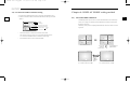
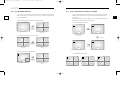
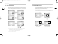
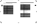
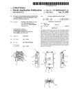
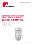
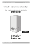
00403A
Cover_SSC-17TQ
10/9/03 11:31 AM
Page 1
COLOR DUAL QUAD
OBSERVATION SYSTEM
SSC-17TQ
INSTALLATION
MANUAL
POWER
00403A SSC-17TQ_ENG
10/9/03 11:30 AM
Page e-2
CAUTION
RISK OF ELECTRIC SHOCK
DO NOT OPEN
e-2
CAUTION : TO REDUCE THE RISK OF ELECTRIC
SHOCK, DO NOT REMOVE COVER
(OR BACK). NO USER SERVICEABLE PARTS
INSIDE. REFER SERVICING TO QUALIFIED
SERVICE PERSONNEL.
Graphic Symbol Explanation
The lightning flash with arrowhead symbol, within an equilateral triangle, is intended to
alert the user to the presence of uninsulated “dangerous voltage” within the product’s
enclosure that may be of sufficient magnitude to constitute a risk of electric shock to
persons.
The exclamation point within an equilateral triangle is intended to alert the user to the
presence of important operating and maintenance (servicing) instructions in the
literature accompanying the appliance.
Warning-To Prevent Fire or Shock Hazard,
Do Not Expose This Equipment To Rain or Moisture.
IMPORTANT SAFEGUARDS
8A. An appliance and cart combination should be moved with care. Quick stops, excessive force, and uneven
surfaces may cause the appliance and cart combination to overturn.
9. Ventilation : Slots and openings in the cabinet are provided for ventilation and to ensure reliable operation of
the video product and to protect it from overheating, and these openings must not be blocked or covered. The
openings should never be blocked by placing the video product on a bed, sofa, rug, or other similar surface.
This video product should never be places near or over a radiator or heat register. This video product should not
be placed in a built-in installation such as a bookcase or rack unless proper ventilation is provided or the
manufacturer's instructions have been adhered to.
10. Power sources : This video product should be operated only from the type of power source indicated on the
marking label. If you are not sure of the type of power supply to your home, consult your appliance dealer or
local power company. For video products intended to operate from battery power, or other sources, refer to the
operating instructions.
11. Power-Cord Protection : Power-supply cords should be routed so that they are not likely to be walked on or
pinched by items placed upon or against them, paying particular attention to cords at plugs, convenience
receptacles, and the point where they exit from the appliance.
12. Lightning : For added protection for this video product during a lightning storm, or when it is left unattended
and unused for long periods of time, unplug it from the wall outlet and disconnect the cable system. This will
prevent damage to the video product due to lightning and power-line surges.
13. Overloading : Do not overload wall outlets and extension cords as this can result in a risk of fire or electric
shock.
14. Object and liquid entry : Never push objects of any kind into this video product through openings as they
may touch dangerous voltage points or short-out parts that could result in a fire or electric shock. Never spill
liquid of any kind on the video product.
15. Servicing : Do not attempt to service this video product yourself as opening or removing covers may expose
you to dangerous voltage or other hazards. Refer all servicing to qualified service personnel.
16. Damage requiring service : Unplug this video product from the wall outlet and refer servicing to qualified
service personnel under the following conditions.
a. When the power-supply cord or plug is damaged.
1. Read instructions: All the safety and operating instructions should be read before the appliance is operated.
b. If liquid has been spilled, or objects have fallen into the video product.
2. Retain instructions: The safety and operating instructions should be retained for future reference.
c. If the video product has been exposed to rain or water.
3. Heed warnings: All warnings on the appliance and in the operating instructions should be adhered to.
d. If the video product does not operate normally by following the operating instructions. Adjust only those
controls that are covered by the operating instruction, as an improper adjustment of other controls may
result in damage and will often require extensive work by a qualified technician to restore the video product
to its normal operation.
4. Follow instructions: All operating and use instructions should be followed.
5. Cleaning: Unplug this video product from the wall outlet before cleaning. Do not use liquid cleaners or aerosol
cleaners. Use a damp cloth for cleaning.
6. Attachments: Do not use attachments not recommended by the video product manufacturer as they may cause
hazards.
7. Water and moisture: Do not use this video product near water - for example, near a bath tub, wash bowl,
kitchen sink, or laundry tub, in a wet basement, or near a swimming pool, and the
like.
8. Accessories : Do not place this video product on an unstable cart, stand, tripod,
bracket, or table. The video product may fall, causing serious injury to a child or
adult, and serious damage to the appliance. Use only with a cart, stand, tripod,
bracket, or table recommended by the manufacturer, or sold with the video
product. Any mounting of the appliance should follow the manufacturer's
instructions and should use a mounting accessory recommended by the
manufacturer.
e. If the video product has been dropped or the cabinet has been damaged.
f. When the video product exhibits a distinct change in performance this indicates a need for service.
17. Replacement parts : When replacement parts are required, be sure the service technician has used
replacement parts specified by the manufacturer or have the same characteristics as the original part.
Unauthorized substitutions may result in fire, electric shock or other hazards.
18. Safety Check : Upon completion of any service or repairs to this video product, ask the service technician to
perform safety checks to determine that the video product is in proper operating condition.
e-3
00403A SSC-17TQ_ENG
10/9/03 11:30 AM
Page e-4
Contents
IMPORTANT SAFEGUARDS...................................................e-2
Chapter 3: Setting each item function at SETUP MENU
3-1) CLOCK/DISPLAY SET MENU function setting .............e-30
e-4
3-2) CHANNEL TITLE MENU function setting .....................e-31
3-3) SYSTEM SET MENU function setting ............................e-32
Chapter 1:
System Components and Installation
1-1) Environmental requirements for installation and safety ....e-6
3-4) EVENT SET MENU function setting ..............................e-34
3-5) EVENT LIST MENU function setting ............................e-36
1-2) System Components.............................................................e-7
1-3) CAMERA Composition and installation method ..............e-9
1-4) CAMERA Composition and connecting method
to SYSTEM........................................................................e-21
1-5) External terminal connecting method for CAMERA and
SYSTEM ...........................................................................e-22
1-6) Whole System connection and configuration ....................e-23
1-7) REAR Panel function..........................................................e-24
1-8) Mounting the DIGITAL DUAL QUAD (SOQ-080N).........e-25
Chapter 2:
REMOTE CONTROL Function and
Using Method
2-1) TALK KEY........................................................................e-26
2-2) VOL+/VOL- KEY ...........................................................e-26
2-3) POWER SAVE- KEY........................................................e-26
2-4) SET- KEY..........................................................................e-27
2-5) QUAD/PAGE- KEY .........................................................e-27
2-6) LIVE/VCR- KEY .............................................................e-27
2-7) PIP- KEY ..........................................................................e-28
2-8) FREEZE- KEY ................................................................e-28
2-9) SEQUENCE- KEY ............................................................e-28
2-10) ZOOM- KEY ...................................................................e-28
2-11) SYSTEM ID - KEY .......................................................e-28
2-12) ENTER- KEY .................................................................e-29
2-13) MENU- KEY ..................................................................e-29
Chapter 4: DISPLAY MODE setting method
4-1) SINGLE SCREEN DISPLAY .........................................e-37
4-2) QUAD MODE DISPLAY
.............................................e-38
4-3) AUTO SEQUENTIAL DISPLAY MODE........................e-39
4-4) PIP MODE DISPLAY .....................................................e-40
4-5) ZOOM MODE DISPLAY ...............................................e-41
Chapter 5: Each product feature
SOD14C : Standard Camera......................................................e-42
SMM-PIRCAM : PIR Camera ..................................................e-43
SOQ-080N : DIGITAL DUAL QUAD .....................................e-44
e-5
00403A SSC-17TQ_ENG
10/9/03 11:30 AM
Page e-6
Chapter 1: System Components and Installation
1-2) System Components
The system consists of the following:
1-1) Environmental requirements for installation and safety
e-6
e-7
This section describes the environmental requirements for safe installation and use.
Install the product on a flat table or in a rack. It should be used only when level and should not be
used when stood vertically or obliquely. The location in which the main system is installed and the
configuration of the wiring room are very important for proper operation of the system.
POWER
When the products are installed too closely together or the location is poorly ventilated, the system
may not operate properly and maintenance of the system may be difficult. Sufficiently circulate the
air within the system operating room and tightly fasten the cover of the main system to prevent
DUAL QUAD
BOX
LCD MONITOR
STANDARD
CAMERA
PIR CAMERA
ALARM
TERMINAL BLOCK
CAMERA Cable
RJ-11 Cable
malfunction and reduce system downs due to environmental causes.
There are high voltage parts inside. Do not arbitrarily open the cover.
Install the product in a place that meets the following environmental conditions. Be sure to maintain
the system under the temperatures and humidity conditions given below:
•
Operating temperature: 0°C ~ 40°C
•
Storage temperature: -20°C ~ 60°C
•
Operating humidity: 20% ~ 85%
•
Storage humidity: 20% ~ 95%
•
Input voltage: AC 100~240V
•
Power usage: less than 30 Watts
•
Frequency: 50/60 Hz
Caution
VCR CABLE
CAMERA BRACKET
POWER CORD &
INSTALLATION MANUAL
Rack Mount Adapter
When operating the product, the fluctuation of input voltage must be within 10% of the rated voltage
and the external power outlet must be grounded, otherwise, it may cause electric shock or malfunction
of the product. Do not connect heat-generating appliances such as a hair dryer, iron or refrigerator to the
same power outlet in which the product is plugged, otherwise it may cause a fire or malfunction of the
product. The use of an Automatic Voltage Regulator (AVR) is highly recommended to ensure that
Screws
(M3 x 6)
Screws
(M4 x 20)
stable power is supplied. Be sure to coil CORE-FERRITE on the connector to reduce electro-magnetic
Monitor Cable
RJ-45 Cable (20M)
interference (EMI).
PLASTIC
ANCHOR
(HUD 5)
Screws
(TH M4 x 15)
Screws
(BH M3 x 30)
Remocon
00403A SSC-17TQ_ENG
10/9/03 11:30 AM
Page e-8
ITEM
MODEL
DESCRIPTION
Q’ty
NOTE
LCD MONITOR
SMT-170
17" TFT-LCD MONITOR
1
-
DIGITAL DUAL QUAD
SOQ-080N
DIGITAL DUAL COLOR
1
-
STANDARD CAMERA
SOD14C
NORMAL TYPE CAMERA
2
-
PIR CAMERA
SMM-
PIR CAMERA
1
Tapping Screw 4
STANDARD TYPE
2
1-3) CAMERA composition and installation method
1) Standard Camera composition (SOD14C)
QUAD SWITCHER
e-8
e-9
PIRCAM
CAMERA BRACKET
SBR-110
(HUD 5=2, BH M3 x 30=2)
CAMERA BRACKET
Tapping Screw 6
(M4 x L15)
CAMERA CABLE
MCB-60
6PIN SHIELD CABLE
2
60ft(1ft=0.3048m)
CAMERA CABLE
MCB-100
6PIN SHIELD CABLE
1
100ft(1ft=0.3048m)
INSTALLATION MANUAL
SSC-17TQ
-
1
-
POWER CORD
-
CBF-POWER CORD
1
-
VCR CABLE
-
BNC DIN CABLE ASSY
1
5P
SENSOR CONNECTOR
-
TERMINAL-BLOCK
2
2P
RACK MOUNT
-
BRACKET-GUIDE
2
Screw 8
ADAPTERS
ACCESSORY CABLE
PIN NUMBER
(M4 x 20=4, M3 x 6=4)
RJ-45 CABLE 8PIN SHIELD CABLE
1
60ft(1ft=0.3048m)
SPEC
!
SPEAKER(HOT)
@
VIDEO_OUT
#
GND
$
SPEAKER(COLD)
%
AUDIO_OUT/ALARM_OUT
^
12V DC
• Check whether all the following devices and accessories are included with the main system.
a. Lens
It has a focal length of 3.8mm and makes it possible for you to observe a relatively wide
area.
b. Microphone
Capable of picking up all sound in the vicinity of the camera location and transmitting to
the monitor.
c. Camera fitting groove
Enables the camera to be fixed onto the bracket. You may install it either above or below
the camera if necessary.
d. 6-pin modular jack
Used to connect the camera to the monitor.
e. SENSOR jack
Used to connect the sensor to the camera.
00403A SSC-17TQ_ENG
10/9/03 11:30 AM
Page e-10
f. Speaker
3) PIR Camera composition
It outputs the sound signal which was transfered from the monitor.
e-10
•
<Top>
PIN configuration of the PIR CAMERA is the same as the STANDARD
<Bottom>
e-11
CAMERA.
•
But, PIR CAMERA does not provide ALARM JACK.
3
2) INSTALLING STANDARD CAMERA (SOD14C)
SOD14C s camera can be attached to the wall, ceiling or shelf using the camera mount bracket
(SBR-110).
5
Choose an installation site that can sufficiently support the weight of the equipments to be installed.
4
Attach the camera mount bracket to the wall or ceiling using the supplied three screws (M4 X L15).
Adjust the camera to target the video location and tighten the bracket handle on the camera mount
1
bracket.
2
① Lens
It has a focal length of 3.8mm and makes it possible for you to observe a relatively wide
area.
➁ Speaker
It outputs the sound signal which was transfered from the monitor.
➂ Fresnel Lens
M4 x L15 sized screws
An infrared focusing lens for increasing the sensitivity of the built-in PIR sensor.
wall or ceiling
00403A SSC-17TQ_ENG
10/9/03 11:30 AM
Page e-12
➃ 6-pin modular jack
<Sensor Detection Angle & Area>
Used to connect the camera to the monitor.
1> Vertical Detection Line
e-12
PIN NUMBER
e-13
SPEC
!
SPEAKER(HOT)
@
VIDEO_OUT
#
GND
$
SPEAKER(COLD)
%
AUDIO_OUT/ALARM_OUT
^
12V DC
• Please consider the horizontal detection area and the vertical detection line when choosing
an installation site.
⑤ 5-Pin Terminal Block
A terminal block for supplying backup power for the PIR sensor operation during power
outages and for transmitting the relay signals to external devices during the PIR sensor
operation.
PIN
SPEC
!
Power Input
DC 12 Volts
@
(Back Up)
Ground
$
Relay Output
COM
%
(350V 130mA)
N.C
#
5
4
3
2
1
Not Used
2> Horizontal Detection Area
00403A SSC-17TQ_ENG
10/9/03 11:30 AM
Page e-14
Camera installation Hints
<Inside>
1. Do not install directly towards rising or setting sun. Can cause burn or damage to internal options.
2. Do not limit desired detection zone by interference of curtains, screens, potted plants, etc.
6
e-14
8
3. Also, do not locate it in front of source of water/oil vapors. Avoid placement of heat source inside
detection zone
7
4. Do not install outdoors.
9
➅ Function Switch
A function switch for the PIR sensor operation.
PIN
ON
!
OFF
S1
!
S2
@
S3
#
S4
$
Function
@
Sensor Sensitivity
On, On : Low
On, Off : Normal
Off, On : Normal
Off, Off : High
#
Alarm Led On/Off (Sensor On)
$
Sensor On/Off
⑦ PIR Sensor
A thermal heat sensor that detects infrared radiation projected by warm objects.
⑧ Microphone
Capable of picking up all sound in the vicinity of the camera location and transmitting to
the monitor.
⑨ Electronic Relay
Output power is 350V/130mA.
e-15
00403A SSC-17TQ_ENG
10/9/03 11:30 AM
Page e-16
4) INSTALLING THE PIR CAMERA (SMM-PIRCAM)
1. Choose an installation site that can sufficiently support 5 times the weight of the equipments to be
4. Connect the Camera connector(RJ-11) cable to the case-rear as well as the cable to be connected to
the terminal.
installed.
e-16
2. Remove the screw (BH M2.6) at the bottom of the main unit by turning it counterclockwise, and
e-17
then lift the assy-case front as you push it upward to detach it from the case-rear.
(❊ Do not apply excessive force, as doing so may damage the inside assembly.❊)
Assy-case front
Screw (BH M2.6)
5. Align the two holes of the case-rear to the holes of the plastic anchors, and then fasten the screwCASE-REAR
tappings (BH M3 X 30).
3. Place the case-rear over the installation site and mark screw holes with a pencil (indicated by the
circles in the illustration). Drill a pilot hole for each pencil mark (5mm in diameter and at least
35mm in depth), and then fully insert the supplied plastic anchors (HUD 5) into them.
SCREW-TAPPING
G(BH M3 x 30)
SCREW-TAPPING
G(BH M3 x 30)
00403A SSC-17TQ_ENG
10/9/03 11:30 AM
Page e-18
6. Adjust the direction of the lens.
4) CAMERA MOUNT BRACKET(SBR-110) & STANDARD CAMERA(SOD14C)
1) Use the cross (+) screw driver to turn the screw (indicated by the arrow in the illustration)
(1) Overview
counterclockwise slightly. The lens body will move.
e-18
2) Tilt the lens body down about 10° from the horizontal, and then turn the screw clockwise to fasten
CAMERA MOUNT BRACKET (SBR-110) is used to attach the camera to a wall, ceiling or shelf.
it.
(2) Installation
Explains the installation of CAMERA MOUNT BRACKET as wall as the installation of the camera
onto the CAMERA MOUNT BRACKET.
•
Choose an installation site that can sufficiently support the weight of the equipments to be
installed.
•
Attach the camera mount bracket to the wall using the supplied screws (M4 X L15).
•
Adjust the camera to target the video location and tighten the bracket handle on the camera
Screw (HB M4 x L8)
7. Assemble the assy-case front onto the case-rear as shown in the illustration. Fasten the assy-case
front to the case-rear with the screw (BH M2.6) you removed earlier.
CASE-REAR
mount bracket. Install the camera on to the male screw of the Camera Mount Bracket by
rotating the camera in clockwise.
Screw (BH M2.6)
ASSY-CASE FRONT
e-19
00403A SSC-17TQ_ENG
•
10/9/03 11:30 AM
Page e-20
Loosen the handle by turning it in a counterclockwise direction and then adjust the camera
1-4) CAMERA Composition and Connecting Method to
SYSTEM
position . Tighten the handle, turning it clockwise, and lock the camera in position.
After positioning monitor and installing three cameras to a desired location, please connect CAMERA
e-20
•
Connect the camera cable to the camera.
to SYSTEM through CAMERA CABLE (MCB-60 or MCB-100) as shown in the below figure. Please
check whether or not it is properly connected.
Handle
(3) Specifications
Use : Indoor
Installation : Wall or Ceiling
Dimensions : 57 (W) X 47.2(H) X 100.5(L)
Weight : 150g
Operating Temperature : -10°C ~ 50°C
(4) Accessories
SCREW (M4 X L15) : 3 pcs
Connection status checking method :
•
Turn on the monitor after connecting cameras, and check if camera image is displayed.
The initial screen mode of monitor is quad mode.
•
If the camera is not connected to the monitor, information on the video loss will be
displayed on the black screen.
e-21
00403A SSC-17TQ_ENG
10/9/03 11:30 AM
Page e-22
1-5) External terminal connecting method for CAMERA and
SYSTEM
f) Connect the A/O (HOT) terminal on the rear panel to the Alarm IN terminal of the VCR.
g) Connect the A/O (COLD) terminal on the rear panel to the Ground terminal of the VCR.
h) Connect the A/R terminal on the rear panel to the Alarm Reset terminal of the VCR.
1) External terminal connecting method for CAMERA
e-22
i) Connect the G (ground) terminal on the rear panel to the Ground terminal of the VCR.
Caution
This Kit is composed of one monitor and three Camera at the Shipping. But this System can
accommodate 8 cameras. So you can buy Cameras Supplementally and add those to the
system.
•
An additional PIR sensor or external sensor can also be connected.
•
The additional PIR sensor can be connected as shown in the above graphic.
•
Sensor’s trigger signal is NO (Normal Open).
•
Sensor is not supplied. (Sold separately)
1-6) Whole System connection and configuration
2) VIDEO OUT BNC (1~8) terminals connecting method of Quad rear
VIDEO OUT BNC1 ~ BNC8 terminals in the rear of the Quad are VIDEO terminals for outputting
video images from OBSERVATION CAMERA to THROUGH OUT.
BNC VIDEO output terminal can be used to connect to VCR (TIME LAPSE) or SLAVE MONITOR.
3) VCR or ALARM terminal connecting method
TIME LAPSE VCR
OR NORMAL VCR
VIDEO IN
VIDEO OUT
AUDIO IN
AUDIO OUT
NOT USED
TRIGGER
VIDEO OUT
VIDEO IN
AUDIO OUT
AUDIO IN
OUT
DUAL QUAD BOX
TFT-LCD MONITOR
a) Connect the 6-pin plug to the VCR terminal on the rear panel.
b) Connect the VIDEO OUT plug to the VIDEO IN terminal of the VCR.
c) Connect the VIDEO IN plug to the VIDEO OUT terminal of the VCR.
d) Connect the AUDIO OUT plug to the AUDIO IN terminal of the VCR.
e) Connect the AUDIO IN plug to the AUDIO OUT terminal of the VCR.
VCR (TIME LAPSE) REAR
e-23
00403A SSC-17TQ_ENG
10/9/03 11:30 AM
Page e-24
1-7) REAR Panel function
1-8) Mounting the DIGITAL DUAL QUAD (SOQ-080N)
ACCESSORY
e-24
e-25
Screws (BH M3X6, 4EA)
Screws (TH M4X20, 4EA)
Rack Mount Adapters (2EA)
a. CAMERA IN (RJ-11)
Video camera input terminals. You Can connect up to 8 Cameras with RJ-11 connectors.
b. CAMERA OUT (BNC)
Video Camera out terminals.
c. VCR
• Connects to the VCR using a 6-Pin connector.
• TRIGGER : Not used
1) Assemble the fixing holes of the
BRACKET-GUIDE to the fixing grooves
underneath both sides of the ASSY
CABINET-BOTTOM, and then screw the
BH M3X6 screws into the specified screw
holes.
Rack Mount
Adapter
• VIDEO IN/OUT : Video input/output terminal for the VCR
• AUDIO IN/OUT : Audio input / output terminal for the VCR
Screw
(BH M3X6)
Screw
(BH M3X6)
d. ALARM
• A/O (HOT/WLD) : When an alarm occurs, the Active Make signal is output.
• A/R : Connects to the Alarm Reset terminal of VCR.
When an alarm is triggered, a pulse is output.
Rack Mount
Adapter
2) Once the BRACKET-GUIDE is assembled
onto the SET, use the BH M4X20 screws to
fix it to the location you want.
e. MON
It Shall be connected to the 17'' TFT-LCD Monitor(SMT-170) with a 20M long Cable
f. ~AC IN
Connects the power cord.
g. Power Switch
It tarns on or off the power.
Screw
BH M4X20
Screw
BH M4X20
00403A SSC-17TQ_ENG
10/9/03 11:30 AM
Page e-26
Chapter 2: REMOTE CONTROL
Function and Using Method
2-4) SET- KEY
Alarm function and loss function can be cancelled
while the alarm or loss is working.
e-26
The Remote Controller(REMOCON) is contained in the 17" TFT-LCD
Monitor (SMT-170).
2-1) TALK KEY
e-27
2-5) QUAD/PAGE- KEY
Allows users to display QUAD A or QUAD B at
QUAD DISPLAY MODE.
TALK KEY allows users to transmit voice signal to
•
intended camera by inputting voice with built-in MIC
in the front of the monitor. For this function, select a
√ SWITCH on the
target camera with the œENTER√
QUAD A: QUAD DISPLAY MODE from Camera
1 to Camera 4
•
QUAD B: QUAD DISPLAY MODE from Camera
5 to Camera 8
FRONT PANEL, if a voice signal is generated through
the MIC with the TALK KEY pressed, the signal will
be transmitted to the camera.
2-6) LIVE/VCR- KEY
Allows users to switch LIVE MODE to VCR MODE
2-2) VOL+/VOL- KEY
or VCR MODE to LIVE MODE. If VCR MODE is
cancelled, the QUAD picture of LIVE MODE will be
Allows users to decrease or increase voice signal
generated from the monitor.
VOL+ : Increase sound volume from the monitor.
VOL- : Decrease sound volume from the monitor.
2-3) POWER SAVE- KEY
Allows users to set POWER SAVE MODE of monitor.
automatically displayed. In case any event happens at
VCR MODE such as LOSS or ALARM, the MODE
will be automatically switched to LIVE MODE, and
the pre-set operation for the event will be carried out.
If there is no external input at VCR MODE, the ICON
“
•
CAMERA is displayed.
PICTURE screen is off when the POWER
SAVE KEY is pressed, and the ON/OFF status of the
” will be displayed.
LIVE MODE: Image and voice signal from
•
VCR MODE: External image and voice signal
monitor can be judged through LED ON/OFF
from VCR terminal from the rear of the monitor is
status. Users can exit from POWER SAVE MODE by
displayed.
pressing POWER SAVE BUTTON again under
picture “OFF” status. POWER SAVE MODE is
automatically cancelled and picture is “ON” when an
event such as an alarm or loss at POWER SAVE
MODE occurs.
00403A SSC-17TQ_ENG
10/9/03 11:30 AM
Page e-28
2-7) PIP- KEY
e-28
2-12) ENTER- KEY
Can be used to see the main screen while Single screen is displayed. The main screen can be changed
As a multi functional ENTER key, it is used for 1. entering from the menu into the submenu, 2. moving
and transfered to another channel while PIP is working. Please refer to "CHAPTER 4. DISPLAY
into the full screen of selected channel.
e-29
MODE SETTING" for PIP function and details.
2-13) MENU- KEY
2-8) FREEZE- KEY
Display the Setup menu on the screen. Press it again to exit the Setup menu.
This key allows users to see a target camera picture at PAUSE MODE. If users select the camera with
the ENTER KEY, and press the FREEZE BUTTON, the FREEZE ICON will be displayed on pause
picture from the camera. In Freeze mode, all keys other than the ZOOM key will be disabled. Other
keys will be enabled again once the Freeze mode is canceled.
2-9) SEQUENCE- KEY
It makes a picture switch sequentially. This means that display the picture will be displayed during the
DWELL TIME pre-set at the DWELL MENU of SETUP MENU, and switch the picture automatically
as a pre-set sequence. Please refer to Chapter 3. DWELL TIME MENU function and setting method for
Note
details of DWELL TIME setting.
The Keys inside this line are not related with System functions.
When these keys are pushed, only beep Sound are generated.
2-10) ZOOM- KEY
It zooms a part of a picture doubling it in the display. If the ZOOM BUTTON is pressed, zoom area
will be displayed. Use the UP, DOWN, LEFT(-), RIGHT(+) buttons to move the zoom area to the
location you want to zoom in. After moving the zoom area to the location you want to zoom in, press
the ENTER button. The zoom area will be zoomed in by 2X.
2-11) SYSTEM ID - KEY
Selects the system to control with the remote. Only the remote control has this button.
00403A SSC-17TQ_ENG
10/9/03 11:30 AM
Page e-30
Chapter 3: Setting each item function at SETUP
MENU
e-30
Pressing the MENU BUTTON of the FRONT PANEL allows users to enter SETUP MENU and see the
following menu OSD box. Setting method of each SETUP MENU function and operation is as follows.
[SETUP MENU]
1.
2.
3.
4.
5.
CLOCK/DISPLAY SET
CHANNEL TITLE
SYSTEM SET
EVENT SET
EVENT LIST
DATE TYPE: MM/DD/YY ↔ YY/MM/DD ↔ DD/MM/YY.
DATE [MM/DD/YY]
• Month(MM) : 01 ~ 12
• Day(DD) : 01 ~ 31
• Year(YY) : 00(2000) ~ 99(2099)
TIME [HH:MM:SS]
• Hour(HH) : 00 ~ 23
• Minute(MM) : 00 ~ 59
• Second(SS) : 00 ~ 59
3-2) CHANNEL TITLE MENU function setting
3-1) CLOCK/DISPLAY SET MENU function setting
•
You may change CHANNEL TITLE.
You may change DISPLAY TYPE, DATE TYPE, or TIME.
If you click the UP/DOWN button to select 2. CHANNEL TITLE in the SETUP MENU
If you click the UP/DOWN button to select 1. CLOCK/DISPLAY SET in the SETUP
and click the ENTER button, the following screen will be displayed.
MENU and click the ENTER button the following screen will be displayed.
[[CHANNEL TITLE]]
CH1
CH2
CH3
CH4
CH5
CH6
CH7
CH8
[CLOCK/DISPLAY SET]
DISPLAY TYPE
DATE TYPE
DATE[MM/DD/YY]
TIME [HH:MM:SS]
ALL
MM/DD/YY
09/01/03
12:30:00
•
•
•
You may click the LEFT/RIGHT button to change the preset value after you set a value
with the UP/DOWN button.
Press the MENU button to return to the SETUP MENU.
DISPLAY TYPE: ALL ↔ TITLE ↔ DATE/TIME ↔ NONE.
• ALL: All items will be displayed except the DATE/TIME and the TITLE.
• TITLE: Only the CHANNEL TITLE will be displayed.
• DATE/TIME: Only the DATE/TIME will be displayed.
• NONE: Neither the DATE/TIME nor the TITLE will be displayed.
•
•
: --CAM1--: --CAM2--: --CAM3--: --CAM4--: --CAM5--: --CAM6--: --CAM7--: --CAM8---
If you click the UP/DOWN button to select CHANNEL and click the ENTER button,
the first “-” will be selected.
If you click the LEFT/RIGHT button to select a text and click the ENTER button, the
system will be prepared to select the next text(in the order of:
0123456789 : = , ( ) ABCDEFGHIJKLMNOPQRSTUVWXYZ[ / ] _ ~
+
Repeat the same to select all the desired letters. (You can choose up to ten letters.)
e-31
00403A SSC-17TQ_ENG
10/9/03 11:30 AM
Page e-32
3-3) SYSTEM SET MENU function setting
PIP POSITION: BOTTOM-RIGHT ↔ TOP-LEFT ↔ TOP-RIGHT ↔ BOTTOM-LEFT.
•
Select the PIP position among the four options listed above.
You may change DWELL TIME, PIP POSITION, BORDER COLOR, LOSS CHANNEL COLOR,
SYSTEM ID.
e-32
If you click the UP/DOWN button to select 3. SYSTEM SET in the SETUP MENU and click the
ENTER button, the following screen will be displayed.
[SYSTEM SET]
DWELL TIME...
PIP POSITION
BORDER COLOR
LOSS CHANNEL COLOR
SYSTEM ID
-
BOTTOM-RIGHT
GRAY
BLACK
1..
Select an item with the UP/DOWN button and change the preset value with the
LEFT/RIGHT button.
Press the MENU button after completing all the settings to return to the SETUP MENU.
BORDER COLOR: GRAY ↔ WHITE ↔ BLACK.
• GRAY : BORDER LINE COLOR is displayed in GRAY in Multi Screen mode
• WHITE : BORDER LINE COLOR is displayed in WHITE in Multi Screen mode
• BLACK : BORDER LINE COLOR is displayed in BLACK in Multi Screen mode.
LOSS CHANNEL COLOR: BLACK ↔ BLUE.
• BLACK: The area corresponding to the channel where video loss has occurred will be
displayed in black.
• BLUE: The area corresponding to the channel where video loss has occurred will be
displayed in blue.
SYSTEM ID
• This function allows the user to control a single monitor using the remote control when
multiple (up to 10) monitors are linked together.
Only those monitors with IDs matching the Remote Control ID will be controlled by the
remote control.
09/01/03 12:30:00
QUAD-A
DWELL TIME...
CAM1
•
CAM2
Select DWELL TIME... with the UP/DOWN button and click the ENTER button.
Then the following screen pops up.
MONITOR ID:1 REMOCON ID:1
CAM3
CAM4
[DWELL TIME]
CH1
CH2
CH3
CH4
QUAD-A
•
03[SEC]
03[SEC]
03[SEC]
03[SEC]
03[SEC]
CH5
CH6
CH7
CH8
QUAD-B
03[SEC]
03[SEC]
03[SEC]
03[SEC]
03[SEC]
Use the UP and DOWN buttons to move the item you want to set, and then use
the LEFT and RIGHT buttons to change the setting value.
•
Press the MENU button after completing the settings to return to the SYSTEM SET Menu.
•
Setting : : The default value of the monitor and remote control 1 . The value of the
Monitor ID can be set from 0 to 9 by accessing the SYSTEM ID Setup mode under the
SYSTEM SET menu. Press the SYSTEM ID button on the remote control to display
the Monitor ID and the Remote Control ID as shown above. Enter the desired number by
pressing the corresponding button (0 to 9) to set up the Remote Control ID.
The OSD will disappear four seconds after the last button is pressed.
e-33
00403A SSC-17TQ_ENG
10/9/03 11:30 AM
Page e-34
3-4) EVENT SET MENU function setting
EVENT DETECT...
You may change EVENT HOLD TIME, EVENT BUZZER, EVENT DETECT.
If you click the UP/DOWN button to select 4. EVENT SET in the SETUP MENU and click the
e-34
•
[EVENT SET]
EVENT HOLD TIME
EVENT BUZZER
EVENT DETECT...
-
Select “EVENT DETECT...” with the UP/DOWN button and click the ENTER button.
e-35
Then the following screen pops up.
ENTER button, the following screen will be displayed.
[EVENT DETECT]
01 [MIN]
ON
Select an item with the UP/DOWN button and change the preset value with the
LEFT/RIGHT button.
Press the MENU button after completing all the settings to return to the SETUP
MENU.
ALARM HOLD TIME : 01[MIN] 03[MIN] 05[MIN] 10[MIN] 20[MIN]
30[MIN] AUTO 05[SEC] 15[SEC] 30[SEC] ...
• An event operation will be carried out for the duration of the event hold time that has
been set.
EVENT BUZZER : ON/OFF
• ON : The buzzer will sound for the duration of the event hold time when an event
occurs.
• OFF : The buzzer will not go off even if an event occurs.
CH
CH1
CH2
CH3
CH4
CH5
CH6
CH7
CH8
•
ALARM
ON
ON
ON
ON
ON
ON
ON
ON
LOSS
ON
ON
ON
ON
ON
ON
ON
ON
Use the UP/DOWN button to move to the item you want to set, and then use the ENTER and
LEFT/RIGHT buttons to change the setting.
•
Press the MENU button after completing the settings to return to the EVENT SET Menu.
00403A SSC-17TQ_ENG
10/9/03 11:30 AM
Page e-36
3-5) EVENT LIST MENU function setting
Chapter 4: DISPLAY MODE setting method
You can check the ALARM/LOSS EVENT LIST. If you click the UP/DOWN button to select
5. EVENT LIST in the SETUP MENU and click the ENTER button, the following screen will be
e-36
displayed.
4-1) SINGLE SCREEN DISPLAY
e-37
The initial display mode is QUAD A mode. Use the UP and DOWN buttons to select the channel you
[EVENT LIST]
MM/DD/YY HH:MM:SS CH
1/ 5
All Pages
Current Page
1. 08/01/03 12:30:01 A 01
2. 08/01/03 12:29:01 L 03
3. 08/01/03 12:28:01 L 01
•
Information on the Channel
Where an Event Took Place
A:Alarm
Event Information
L:Loss
Event Occurrence Time
want to view on a single screen, and then press the ENTER button. The channel you selected will be
displayed on a single screen.
Alternatively, you can press the corresponding channel number key on the remote control to switch to a
single screen.
The latest information on Alarms and Loss Detects will be stored.
This system stores up to 50 events (10 x 5 pages) staring from the latest one.
•
Press the MENU button to return to the SETUP MENU.
09/01/03 12:30:00
QUAD-A
09/01/03 12:30:00
QUAD-A
You can click the UP/DOWN button to check the list of other pages.
CAM1
CAM2
CAM3
CAM4
➯
CAM1
CAM2
CAM3
CAM4
Press ENTER
button after
selecting CAM2
➯
INITIAL DISPLAY STATUS
09/01/03 12:30:00
09/01/03 12:30:00
CAM 1
FULL SCREEN DISPLAY of CAM1
Select CAM2 by the
Up/Down button
Display
CAM1 by
Up/Down
Button
CAM 2
FULL SCREEN DISPLAY of CAM2
00403A SSC-17TQ_ENG
10/9/03 11:30 AM
Page e-38
4-2) QUAD MODE DISPLAY
Users can switch SINGLE DISPLAY MODE and SEQUENTIAL DISPLAY MODE to QUAD
Pressing on the SEQUENCE KEY on the front allows screen to automatically switch to SINGLE
DISPLAY MODE, or QUAD A (QUAD B) to QUAD B (QUAD A), or PIP MODE to QUAD MODE,
MODE full screen or QUAD MODE. (‘no-signal’ channels will be skipped while single screen is
press the QUAD/PAGE KEY.
auto-switching.)
e-39
If the DWELL TIME SETTING of SETUP MENU is set to 3 seconds and the SEQUENCE KEY is
* At QUAD MODE display from SINGLE MODE or SEQUENCE MODE,
* SINGLE MODE SEQUENCE DISPLAY
08/01/03 12:30:00
QUAD-A
08/01/03 12:30:00
➯
CAM3 DISPLAY
CAM1
CAM2
CAM3
CAM4
➯
In 3 seconds
QUAD MODE DISPLAY
of QUAD A
CAM4
➯
CAM3
Automatic sequential switching to CAM3
08/01/03 12:30:00
QUAD-B
08/01/03 12:30:00
QUAD-A
CAM2
CAM 3
CAM 2
Press SEQUENCE KEY
when CAM2 is displayed
at full screen
* At QUAD B(QUAD A) display from QUAD A(QUAD B),
CAM1
08/01/03 12:30:03
08/01/03 12:30:00
Press
QUAD/Page
KEY
CAM 3
pressed at this time, the operation will be carried out as follows.
➯
Press
QUAD/Page
KEY
QUAD MODE DISPLAY
of QUAD A
CAM5
CAM6
CAM7
CAM8
In 3 seconds
08/01/03 12:30:06
08/01/03 12:30:09
➯
e-38
4-3) AUTO SEQUENTIAL DISPLAY MODE
In 3 seconds
QUAD MODE DISPLAY of
QUAD B
CAM4
CAM 5
Automatic sequential switching to CAM5
Automatic sequential switching to CAM4
* At QUAD B(QUAD A) display from PIP MODE,
08/01/03 12:30:00
QUAD-A
08/01/03 12:30:00
PIP-A
➯
CAM 2
CAM 1
PIP MODE DISPLAY
Press
QUAD/Page
KEY
CAM1
CAM2
CAM3
CAM4
QUAD MODE DISPLAY of
QUAD A
* QUAD MODE SEQUENCE DISPLAY
08/01/03 12:30:00
QUAD-A
CAM1
CAM2
CAM3
CAM4
08/01/03 12:30:03
QUAD-B
➯
CAM5
CAM6
CAM7
CAM8
08/01/03 12:30:06
QUAD-A
➯
CAM1
CAM2
CAM3
CAM4
00403A SSC-17TQ_ENG
10/9/03 11:30 AM
Page e-40
4-4) PIP MODE DISPLAY
This is available in Single Screen mode.
While in a single screen display, press the ZOOM key to display the zoom area.
When in a PIP screen, you can use the UP and DOWN buttons to change the main channel and use the
Use the LEFT, RIGHT, UP, and DOWN keys to move to the area you want to zoom in, and then press
ENTER key to switch between the main and sub screens. In addition, you can change the location of the
the ENTER key. The area you selected will be displayed enlarged by 2x.
sub screen in the SYSTEM SET submenu of the SETUP MENU.
While the zoomed area is displayed, you can use the directional keys to move the zoom area to the
e-41
location you want to monitor.
08/01/03 12:30:00
PIP-A
08/01/03 12:30:00
PIP-A
To exit from ZOOM mode, press the ZOOM key again. The screen will return to Single Display mode.
➯
CAM 3
Press ENTER
KEY
08/01/03 12:30:00
CAM 1
CAM 1
08/01/03 12:30:00
CAM 3
Under PIP DISPLAY
➯
Main and Sub screen is switched
08/01/03 12:30:00
PIP-A
08/01/03 12:30:00
PIP-A
➯
CAM 1
CAM 2
CH2 SINGLE DISPLAY
Press UP/DOWN
KEY
Under PIP DISPLAY
CAM 2
ZOOM area is activated.
CAM 3
➯
CAM 3
Press ZOOM
KEY
CAM 2
Main screen is switched
08/01/03 12:30:09
08/01/03 12:30:00
PIP-A
➯
Press PIP KEY
CAM 2
CAM1
Under single screen display
CAM 1
The main and sub screens will be
displayed according to the PIP
position you have set in the
SYSTEM SET submenu of the
SETUP MENU.
* When sub picture is fixed if you push the sequence key. channel of releated page (Quad A or B)
except main channel will be switching according to the dwell time setting value.
However, any loss channel will be skipped during the switching.
* Sequence mode is toggled by sequence key.
08/01/03 12:30:00
08/01/03 12:30:00
Z
➯
e-40
4-5) ZOOM MODE DISPLAY
CAM 2
The selected area will be doubled
and at FULL DISPLAY.
Press
œENTER√
√
SWITCH
CAM 2
Use the directional keys to move the
zoom area to the desired location.
00403A SSC-17TQ_ENG
10/9/03 11:30 AM
Page e-42
Chapter 5: Each product feature
e-42
SOD14C : Standard Camera
SMM-PIRCAM : PIR Camera
Model Name
SMM-PIRCAM
Broadcasting System
NTSC STANDARD
1/4'' SUPER HAD IT CCD
Model Name
SOD14C
Imaging Device
Broadcasting System
NTSC STANDARD
Effective Pixels
510(H) x 492(V)
Imaging Device
1/4 ”SUPER HAD IT CCD
Synchronization
Internal
Effective Pixels S
510(H) x 492(V)
Resolution
330 TV Lines(H), 350 TV Lines(V)
Synchronization
Internal
Signal Output
VBS 1.0Vp-p(75ohms composite)
Resolution
H :330 TV Lines, V: 350 TV Lines
S/N Ratio
≤ 48 dB
Signal Output
VBS 1.0Vp-p(75ohms composite)
Minimum Scene Illumination
2 lux(F2.0, 50 IRE)
S/N Ratio
≤ 48 dB
Gamma Correction
0.45
Minimum Scene Illumination
2lux(F2.0, 50 IRE)
Lens
Focal Length (f) : 3.8mm, F Number : 2.0
Gamma Correction
0.45
Auto Exposure
Electronic Shutter lris
Lens
Focal Length (f) : 3.8mm, Aperture Ratio (F) : 2.0
Mounthy height : 1.5m to 3m (5ft to 10ft)
Auto Exposure
Electronic Shutter lris
Warm-Up Period :Max. 50 seconds
Audio
-40dB Condenser Microphone Inclusion
I/O Connectors
Modular jack (RJ-11)
Operating Temperature
-10 ~ +50 °C
Detectivity : 1.5 x 108cm Hz 2/1/W
Power Source
DC 12V
Sensor : Off/On
Power Consumption
Approx. 2W
Alarm LED : Off/On (0.3 to 2 second)
Dimensions
57(W) x 47.2(H) x 100.5(L)
Weight
150g
Spectral Response : 5 to 14 um
PIR Sensor
Sensitivity : 4860(V/W)
Alarm Output : NC (350V/130mA)
Audio
-40 dB Condenser Microphone Inclusion
I/O Connectors
Modular jack (RJ-11)
Operating Temperature
-10 ~ +50 °C
Power Source
DC 12V (Camera & Sensor from Monitor)
DC 12V (External Power Supplier)
Power Consumption
Approx. 2W
Dimensions
40(W) x 69.5(H) x 115(L) mm
Weight
About 200g
e-43
00403A SSC-17TQ_ENG
10/9/03 11:30 AM
Page e-44
Memo
SOQ-080N : DIGITAL DUAL QUAD
Video Input
• CAMERA 8 Input: 1.0Vp-p(CVBS), 75Ω
• VCR 1 Input (to Video Out of VCR) : 1.0Vp-p, 75Ω
e-44
Video Output
• BNC 8 Output: 1.0 Vp-p, 75Ω, S-Jack Type, CVBS
• VCR 1 Output: 1.0 Vp-p, 75Ω , S-Jack Type, CVBS
Voice Input
• CAMERA 8 Input:
• VCR 1 Input (to Audio Out of VCR) : S-Jack Type
Voice Output
• CAMERA 8 Input:
• VCR 1 Output: S-Jack Type
Alarm/Motion Features:
A/O (HOT, COLD) : Relay Active
Connected to Alarm
A/R (Alarm Reset) : Open Collector “L” Level,
Pulse Width =150ms or above
Box/Camera
Alarm Hold Time : Select 5 sec, 15 sec, 30 sec, 1 min, 3 min,
5 min, 10 min, 20 min, 30min., or AUTO
Sequence
Select between 00 sec to 30 sec.
Event List
(max) 50 case
Display mode
Single mode, Quad A mode, Quad B mode, PIP, Sequence
Freeze, Zoom(X2)
Horizontal Resolution
400TV Lines or more (Live Mode Full Screen)
Operation Temperature
0 °C ~ 40 °C
Dimension (W x D x H (mm))
345 x 240 x 48 mm
Weight
Approx. 1.8 kg(exclusive of packing materials)
Power consumption
30W
Video system
NTSC VIDEO SYSTEM
Operation Humidity Range
0~90%
AC Input Ranges
AC100 ~ 240V(50/60Hz)
00403A SSC-17TQ_ENG
Memo
10/9/03 11:30 AM
Page e-46
00403A
Cover_SSC-17TQ
Samsung CCTV dba GV1
1621 West Crosby, Suite 104
Carrollton, TX. 75006
PHONE : 866.492.8246
10/9/03 11:31 AM
Page 2
Part No.: AB68-00403A (Rev.01)
Printed in Korea