1
INSTRUCTION MANUAL
DSR-3716PA
DSR-3709PA
Digital Video Recorder
with Multiplexer Function
About this manual
Before installing and using this unit,
please read this manual carefully.
Be sure to keep it handy for later reference.
DSR-3716PA
DSR-3709PA
Table of Contents
Foreword
Safety precautions . . . . . . . . . . . . . . . . . . . . . . . . . . . . . . . 3
These must be followed for safety reasons . . . . . . . . 3
Follow the points outlined below for proper use . . . . 5
Main Features . . . . . . . . . . . . . . . . . . . . . . . . . . . . . . . . . . . 7
Accessories . . . . . . . . . . . . . . . . . . . . . . . . . . . . . . . . . . . . 7
Names and functions of parts (front panel) . . . . . . . . . . . 8
Names and functions of parts (rear panel) . . . . . . . . . .
Basic connections . . . . . . . . . . . . . . . . . . . . . . . . . . . .
Alarm and RS-485 connections . . . . . . . . . . . . . . . . .
Network connection terminals (LAN). . . . . . . . . . . . .
Control terminals (CONTROL) . . . . . . . . . . . . . . . . . .
10
10
11
11
12
How to use
Preparing for use . . . . . . . . . . . . . . . . . . . . . . . . . . . . . . .
Turn on the power of the DVR . . . . . . . . . . . . . . . . . .
Language, clock settings . . . . . . . . . . . . . . . . . . . . . .
Operation display . . . . . . . . . . . . . . . . . . . . . . . . . . . .
13
13
13
14
Viewing live video using various multi screens . . . . . .
Switching to another full-screen video . . . . . . . . . . .
Quad-screen display switching . . . . . . . . . . . . . . . . .
Multi-screen display switching. . . . . . . . . . . . . . . . . .
Enlarging an image in multi-screen mode . . . . . . . .
Automatic screen scrolling. . . . . . . . . . . . . . . . . . . . .
Viewing on the monitor connected to the MON2
terminal. . . . . . . . . . . . . . . . . . . . . . . . . . . . . . . . . . . . .
15
15
15
15
15
16
16
Recording video to the hard disk . . . . . . . . . . . . . . . . . . 17
Recording format verification. . . . . . . . . . . . . . . . . . . 17
Normal recording (normal recording area) . . . . . . . . 17
Viewing recorded video . . . . . . . . . . . . . . . . . . . . . . . . . .
Playback . . . . . . . . . . . . . . . . . . . . . . . . . . . . . . . . . . . .
Full-screen viewing . . . . . . . . . . . . . . . . . . . . . . . . . . .
Fast-forward/fast-reverse during playback . . . . . . . .
Changing the playback speed . . . . . . . . . . . . . . . . . .
Viewing still images . . . . . . . . . . . . . . . . . . . . . . . . . .
Frame advance (forward and reverse). . . . . . . . . . . .
Enlarged viewing . . . . . . . . . . . . . . . . . . . . . . . . . . . . .
Quad-screen viewing . . . . . . . . . . . . . . . . . . . . . . . . .
Multi-screen (9/16) viewing . . . . . . . . . . . . . . . . . . . . .
18
18
18
18
19
19
19
20
20
20
Searching for recorded video . . . . . . . . . . . . . . . . . . . . . .21
A Alarm search . . . . . . . . . . . . . . . . . . . . . . . . . . . . . .22
B Alarm thumbnail search . . . . . . . . . . . . . . . . . . . . .22
b Viewing pre-alarm video . . . . . . . . . . . . . . . . . . . .22
C Date/time search . . . . . . . . . . . . . . . . . . . . . . . . . . .23
b Viewing the preview screen. . . . . . . . . . . . . . . . . .23
D Archive area search . . . . . . . . . . . . . . . . . . . . . . . . .24
E Motion detection search . . . . . . . . . . . . . . . . . . . . .24
b Motion sensor settings verification
using the preview screen. . . . . . . . . . . . . . . . . . . .26
b Full-screen viewing of video detected
by the motion sensor . . . . . . . . . . . . . . . . . . . . . . .26
Copying recorded video to media . . . . . . . . . . . . . . . . . .27
A Copying video (example: 10 seconds)
from the normal or alarm recording area
to the archive area . . . . . . . . . . . . . . . . . . . . . . . . . .28
B Copying video (example: 10 pictures)
from the internal hard disk
to the CD-R/RW drive . . . . . . . . . . . . . . . . . . . . . . . .29
C Copying video (example: 10 pictures)
from the internal hard disk to media
such as a CompactFlash card . . . . . . . . . . . . . . . .30
D Printing images directly from the CompactFlash
card or the microdrive . . . . . . . . . . . . . . . . . . . . . . .31
CompactFlash cards or CD-RW formats . . . . . . . .32
b CompactFlash format . . . . . . . . . . . . . . . . . . . . . .32
b CD-RW format. . . . . . . . . . . . . . . . . . . . . . . . . . . .32
Viewing Images copied
to a CompactFlash card on a PC . . . . . . . . . . . . . .32
How to set
Main menu configuration . . . . . . . . . . . . . . . . . . . . . . . . .33
Basic settings . . . . . . . . . . . . . . . . . . . . . . . . . . . . . . . . . .34
Menu configuration. . . . . . . . . . . . . . . . . . . . . . . . . . . .34
b Displaying the basic settings screen . . . . . . . . . . .34
A Summer time setting . . . . . . . . . . . . . . . . . . . . . . . .35
A-1 External clock setting (EXT. CLOCK SET) . . . . .35
B Camera detection . . . . . . . . . . . . . . . . . . . . . . . . . . .35
C Title setting . . . . . . . . . . . . . . . . . . . . . . . . . . . . . . . .36
D Holiday setting . . . . . . . . . . . . . . . . . . . . . . . . . . . . .36
E Time period setting . . . . . . . . . . . . . . . . . . . . . . . . .37
b Changing the time period of operations . . . . . . . .38
b Setting the times for the time periods . . . . . . . . . .38
English
Recording settings . . . . . . . . . . . . . . . . . . . . . . . . . . . . . .39
Menu configuration. . . . . . . . . . . . . . . . . . . . . . . . . . . .39
b Displaying the recording settings screen. . . . . . . .39
A Easy recording menu description . . . . . . . . . . . . .40
A-1 Easy recording settings 1 . . . . . . . . . . . . . . . . . . .41
A-2 Easy recording settings 2 . . . . . . . . . . . . . . . . . . .42
1
Foreword
Table of Contents
B Recording area menu description. . . . . . . . . . . . . 43
E Network settings . . . . . . . . . . . . . . . . . . . . . . . . . . .69
b Verifying the capacity of the recording areas . . . .
B-1 Changing the normal recording area
and the alarm recording area . . . . . . . . . . . . . . .
B-2 Archive area full reset . . . . . . . . . . . . . . . . . . . . .
C Recording conditions menu description . . . . . . .
b Remaining hard disk capacity warning. . . . . . . . .
C-1 Overwrite setting for the recording areas . . . . .
C-1
C-2 Setting series recording . . . . . . . . . . . . . . . . . . .
C-3 Series recording . . . . . . . . . . . . . . . . . . . . . . . . . .
C-4 Setting the storage period (AUTO DELETE)
for videos recorded in the recording areas . . . .
D Normal recording area menu description. . . . . . .
D-1 Normal recording area settings . . . . . . . . . . . . .
E Programmed recording menu description . . . . . .
E-1 Programmed recording settings . . . . . . . . . . . . .
F Timer setting menu description . . . . . . . . . . . . . .
b Timer-controlled recording . . . . . . . . . . . . . . . . . .
b If the timer settings are overlapping . . . . . . . . . . .
b If the Day of the week and Daily settings
are overlapping . . . . . . . . . . . . . . . . . . . . . . . . . .
b Cancelling timer-controlled operations. . . . . . . . .
F-1 Day of the week timer-controlled
recording (same time, same recording rate
every week for the specified day) . . . . . . . . . . . .
F-2 Overlapping timer-controlled recording. . . . . . .
F-3 External timer-controlled recording . . . . . . . . . .
G Alarm recording settings menu description . . . .
G-1 Alarm recording settings . . . . . . . . . . . . . . . . . . .
G-2 Pre-alarm recording settings . . . . . . . . . . . . . . .
G-3 Alarm trigger setting . . . . . . . . . . . . . . . . . . . . . .
b Input signals used as external alarms . . . . . . . . .
G-4 Motion sensor screen description . . . . . . . . . . .
G-5 Motion sensor setting . . . . . . . . . . . . . . . . . . . . .
H Alarm operation settings menu description. . . . .
H-1 Alarm operation settings . . . . . . . . . . . . . . . . . . .
H-2 Alarm display settings . . . . . . . . . . . . . . . . . . . . .
b Alarm cancellation . . . . . . . . . . . . . . . . . . . . . . . .
E-1 Network password modification . . . . . . . . . . . . .69
F RS-485 settings . . . . . . . . . . . . . . . . . . . . . . . . . . . .70
G Camera control settings . . . . . . . . . . . . . . . . . . . . .71
G-1 Alarm recording trigger settings . . . . . . . . . . . . .72
44
45
46
46
47
47
48
48
49
49
50
50
51
51
51
51
51
G-2 Camera control from the DVR . . . . . . . . . . . . . . .73
Screen setting . . . . . . . . . . . . . . . . . . . . . . . . . . . . . . . . . .74
Menu configuration. . . . . . . . . . . . . . . . . . . . . . . . . . . .74
b Displaying the screen settings. . . . . . . . . . . . . . . .74
A Changing the multi-screen sequence . . . . . . . . . .75
B Automatic scrolling of live video
of the main monitor and the monitor 2
at identical intervals (example: 5 seconds) . . . . . .76
B-1 Automatic scrolling of live video
of the main monitor and the monitor 2
at individual intervals (example: 5 seconds) . . .76
B-1
B-2 Automatic sequence of live video
of the main monitor (full-screen) at individual
intervals, and of the monitor 2 at identical
intervals (example: 3 seconds) . . . . . . . . . . . . . .77
B-1
B-3 Turning off display of specified cameras
during timer-controlled periods . . . . . . . . . . . . . .77
C Masking specific camera images . . . . . . . . . . . . . .78
D Adjusting color tones of the live video . . . . . . . . .79
52
53
54
55
56
57
57
57
58
59
60
61
61
61
Power loss information/Used time . . . . . . . . . . . . . . . . . .80
A Power loss/Used time menu description . . . . . . . .80
A-1 Viewing the information . . . . . . . . . . . . . . . . . . . .80
62
62
62
63
64
65
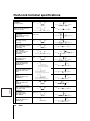
Specifications . . . . . . . . . . . . . . . . . . . . . . . . . . . . . . . . . .85
Initialization log . . . . . . . . . . . . . . . . . . . . . . . . . . . . . . . . .81
A Initialization log menu description . . . . . . . . . . . . .81
A-1 Viewing the log . . . . . . . . . . . . . . . . . . . . . . . . . . .81
Menu copy . . . . . . . . . . . . . . . . . . . . . . . . . . . . . . . . . . . . .82
A Menu copy screen description . . . . . . . . . . . . . . . .82
A-1 Save the menu content in the CF card. . . . . . . . .82
A-2 Load menu content saved to the CF card
onto other DVRs of the same model. . . . . . . . . . .83
Other
Interface (RS-485) specifications . . . . . . . . . . . . . . . . . . .84
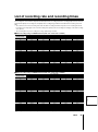
List of recording rate and recording times . . . . . . . . . . .86
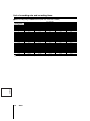
List of record rate setting/
pre-alarm recording times . . . . . . . . . . . . . . . . . . . . . . . .88
Push-lock terminal specifications . . . . . . . . . . . . . . . . . .89
List of camera addresses . . . . . . . . . . . . . . . . . . . . . . . . .90
65
66
66
English
General settings . . . . . . . . . . . . . . . . . . . . . . . . . . . . . . . .
Menu configuration . . . . . . . . . . . . . . . . . . . . . . . . . . .
b Displaying the general settings screen . . . . . . . .
A Data display settings/VIDEO LOSS settings . . . .
B Buzzer settings . . . . . . . . . . . . . . . . . . . . . . . . . . . .
C Security lock menu description. . . . . . . . . . . . . . .
C-1 Turn ON the ADMIN and USER security locks
and set passwords for the DVR . . . . . . . . . . . . .
C-2 Activating the security lock. . . . . . . . . . . . . . . . .
C-3 Cancelling the security lock . . . . . . . . . . . . . . . .
b List of permitted operations after setting the
passwords . . . . . . . . . . . . . . . . . . . . . . . . . . . . . .
D Hard disk settings menu description . . . . . . . . . .
D-1 Hard disk initialization . . . . . . . . . . . . . . . . . . . . .
43
67
68
68
Foreword
2
Safety precautions
These must be followed for safety reasons
Warning
b Do not use if the unit emits smoke, or
while abnormal sounds and smells
are detected.
Using in an abnormal condition may cause
electrocution and fires. Immediately remove
the power cable from the outlet, confirm that
there no smoke is emitting and request
repairs at the dealership or factory shop
where this unit was purchased.
Do not attempt repairs on your own.
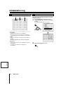
b Do not use during thunder/thunder storms.
Remove the power
cable from the
outlet.
This may cause accidents and damage
through falling or toppling.
Turn the power off and remove the power
cable from the outlet when the unit has been
dropped or the cabinet has been damaged.
Contact the dealership or factory shop where
you purchased this unit.
Using continuously may cause electrocution
and fires.
Prohibited
Remove the power
cable from the
outlet.
Disassembly
prohibited.
b Do not expose to shock or vibration.
Stored data may be damaged/lost through
hard-disk breakdowns caused by shock/
vibration.
b Do not expose to water.
• This unit is not waterproof. Do not expose
to water. This may cause fires and/or
electrocution.
Do not use in bathrooms.
• Turn the power off and remove the power
cable from the outlet if the internal
components have been exposed to water.
Contact the dealership or factory shop
where you purchased this unit. Continuing
to use may cause electrocution and fires.
Contact prohibited
b Do not place in an unstable position.
b Do not disassemble or modify.
Do not place your hand in the internal areas
of this unit as this may cause fires and/or
electrocution.
Request for inspections, adjustments, and
repairs at the dealership where you
purchased this unit or at a factory shop.
Do not use during thunder/thunder storms.
Never make contact with the connection
cable. This may cause electrocution.
Prohibited
Exposing to water is
prohibited.
b Do not use this unit where it is exposed to the
possibility of explosion.
Do not use this unit in areas where explosive
and/or flammable gases are present. This
may cause fires and/or explosions.
Prohibited
Using around water
is prohibited.
Please note:
English
Your SANYO product is designed and manufactured with high quality materials and components which can be recycled and reused.
This symbol means that electrical and electronic equipment, at their end-of-life, should be disposed of separately from your household
waste.
Please dispose of this equipment at your local community waste collection/recycling centre.
In the European Union there are separate collection systems for used electrical and electronic products.
Please help us to conserve the environment we live in!
This symbol mark and recycle system are applied only to EU countries and not applied to the countries in the other area of
the world.
3
Foreword
Safety precautions
Caution
b Delivery and portability
b Do not expose to extreme temperatures or
temperature variations.
Remove the power
cable from the
outlet.
b Maintenance where the unit is going to remain
unused for long periods
Remove the power cable from the outlet.
Carrying out maintenance without removing
the power cable may cause electrocution.
• Do not place in areas where the unit will
be exposed to extreme temperatures (±10
degrees Centigrade per hour) or moisture
changes.
Prohibited
Do not operate when the unit is in a state
of condensation.
Operating when the unit is in a state of condensation may
cause breakdowns. When exposed to extreme
temperature changes, turn the power off and leave the unit
for approximately two hours (until the surrounding
temperature stabilizes) and then start the unit.
b Cautionary points on condensation
Remove the power
cable from the
outlet.
b Cleaning the internal components
Consult the dealership or factory shop where
you purchased this unit for cleaning internal
components. Leaving the unit unused for long
periods of time may attract dust to the
internal components, which in turn may
cause fires and/or breakdowns.
b Do not block the cooling fans or air ducts.
• This unit is equipped with air ducts and
cooling fans in order to assist the
ventilation of hot air produced by the hard
Prohibited
disk drive.
Placing covers, placing in a case, or
placing inside book cases may cause heat
build up, and may result in fire and/or
electrocution.
When the unit is setup in a rack leave open space on
all sides.
• Leave 1 cm or more of space above and below.
• Leave 5 cm or more of space on both sides and on the
back side.
Condensation will result if cold water is poured into a cup.
The internal components of this unit are also susceptible
to the same condition. This condition is called
condensation.
Using this unit while condensation is present may cause
breakdowns.
Take care to avoid condensation when the environment
experiences sudden changes of temperature while the
power is turned off (room where the unit is placed is
heated quickly).
Condensation will not occur while the power is turned on.
When condensation is likely to result...
Use after turning the power off and leaving for 1~2 hours.
b Points on unit positioning
This unit is constructed using precision
electronic parts. Avoid placing it in areas
Prohibited
described below as this may cause faulty
operation and/or breakdowns.
• In direct sunlight
• In places exposed to water
• In the vicinity of cooling and heating devices or
humidifiers
• Near the air conditioner where the unit is exposed to
cool air
• Dusty areas
• Areas that contain fire hazards
• Areas that contain magnetic items
• In the vicinity of volatile substances
• Areas where the unit will be exposed to constant
vibration (in trains, cars, etc.)
Foreword
4
English
• Never move this unit while the power is
turned on.
• Remove the power cable from the outlet,
confirm that the connection cable has
been removed, and store in original
packaging before delivering. Deliver using
a method that causes the least amount of
shock and/or damage to this unit. Also, do
not drop this unit.
Safety precautions
Follow the points outlined below for proper use
b Hard disk
This unit is loaded with a hard disk drive. Stored data on this unit may be damaged/lost through hard-disk breakdowns caused
by shock/vibration.
Follow the items outlined below when placing, transporting, and operating this unit.
Warning
G This unit is designed to be positioned horizontally.
Do not position vertically.
G Do not expose to shock or vibration and do not
transport while power is turned on.
Always turn the power off, even when moving in and out of
racks.
G Do not remove the power cable while recording or
playing back.
G Do not move the unit for approximately 30 seconds
after turning the power off.
The hard disk is rotating for a short duration after the
power is turned off. The unit is further susceptible to
damages through shock and vibration in this state
compared to when the power is turned on. Do not move it.
G Do not expose to shock or vibration.
Avoid placing this unit directly on the floor. Make sure that
the four stands attached to the base of this unit are used,
when placing it on the floor.
G Always use the original packaging (packaging
provided at the time of purchase), when delivering.
Use the packaging materials provided during the original
purchase when the unit or a single internal component is
going to be delivered. Deliver using a method that causes
the least amount of shock and/or damage to this unit.
Cooling fan
English
5
Foreword
Warning
G Inspecting for abnormalities in the hard disk drive and
the cooling fan
This unit is designed to automatically check the drive and
cooling fan when the power is turned on. Replacement
parts will be necessary if abnormalities are detected.
Images will have to be saved and initialization will have to
take place if there is a fault with the drive. Consult the
dealership where this unit was purchased for details.
G Wear in the hard disk drive and the cooling fan
The hard disk drive and cooling fan are consumable
items.
Replace the parts stated below when using the unit in a
25°C environment. The replacement timings listed are
approximate and do not guarantee the performance or life
expectancy of the part in question.
• Hard disk: 2 years
• Cooling fan: 3 years
• Damper: 2 years
Consult the dealership where the unit was purchased
for replacement drives.
• The drive is vulnerable to static electricity shocks. Take
the appropriate measures to prevent exposure to static
electricity.
• Unpackaged drives should be placed horizontally with
their base facing upwards on top of a soft cloth.
Exposing the drive to shocks and vibration may cause
breakdowns.
• Do not expose the drive to shocks and vibrations while
removing/tightening the screws during replacement.
Firmly tighten the screws after replacement.
Safety precautions
b Back up battery
• A lithium battery (fixed) is built into this unit. Supplying
power for more than 48 hours after setting the date and
time will allow the internal power source to sustain the
set time for 7 days.
• The battery is expected to last for approximately 5
years if the unit is used regularly.
• Battery fluid leaks
Rinse hands/clothes thoroughly with water in case
battery fluid has leaked.
Loss of eyesight may result if battery fluid enters the
eyes. Do not rub. Immediately rinse with clean water
and consult a physician.
The following symptoms will result if the battery is
leaking or has reached the end of its life expectancy.
Consult the dealership where this unit was purchased
or the nearest repair center for replacements.
• The clock is automatically reset once the power
source is cut.
• Does not return to automatic standby.
• The image number is not recorded.
When disposing of this unit
Consult the dealership where the unit was purchased for the
disposal process of the lithium battery.
b Pre-confirm important recording
assignments.
Recording and/or playing back functions may be
unavailable due to hard-drive or connecting device failures.
Always confirm that recording can be carried out
successfully before carrying out important recording
assignments. The recorded content cannot be guaranteed.
It is recommended that periodic back ups or mirroring is
conducted in order to prevent breakdowns or recording
faults through accidents.
b Maintaining this unit
Turn the power off and remove the power cable from
the outlet.
Wipe away dust using a soft cloth.
When the stains are hard to remove...
Soak the cloth in water with diluted neutral detergent.
Wipe the stain and moisture away with a dry cloth.
Cautionary points
• Do not use paint thinner, benzine, or any other alcohol
based agents for cleaning. The exterior may deteriorate
or the paint may wear off.
• Follow the instructions provided on the packaging of the
chemical cleaning agent.
• Do not spray volatile substances, such as insecticides,
etc. onto the unit.
• Also, avoid direct contact of rubber or vinyl products
with the unit.
This may cause the exterior to deteriorate or the paint
to wear off.
b Copyright information
• This manual and software are copyrighted by Sanyo
Electric Co., Ltd.
• Brand and product names used in this manual are the
trademarks or registered trademarks of their respective
companies.
Except for personal use, copyright law prohibits the use of
recorded copyrighted images without the permission of the
copyright holder.
b Copy right
Copy right laws prohibit unauthorized duplication of copy
right protected images except for private use.
b If unused for a lengthy period of time
English
Remove the power cable from the outlet. Remember to
occasionally turn the power on in order to maintain correct
function.
Foreword
6
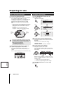
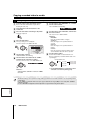
Main Features
Accessories
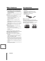
b This digital video recorder (DVR) can record video
from surveillance cameras to its internal hard disk,
and it can display the video on a screen split into
sixteen, thirteen, nine, six or four fields, both during
recording, and playback.
The DSR-3709PA can split the screen into nine, six or four
fields only.
Check that you have all the parts shown below.
• Quick Guide
• Instruction Manual (Digital Video Recorder)
• Manual for Remote Operation using a Network
Connection
• Mounting screws for hard disk x8
• Power cable/Cord tie
b Complete range of recording and playback functions
• Simultaneous recording and playback.
• Timer-controlled recording allows for different recording
schedules for each day of the week.
• Zoom function allows for enlarging images during
surveillance and playback.
• Alarm recording allows for recording the actions of
intruders.
• Masking function allows for masking the video from
specific cameras using a gray pattern, preventing it from
being monitored.
• Motion sensing can be used with each camera and alarm
operation can be used to give priority to the recording of
moving subjects.
b Search function allows for instant display of the
desired recording (P21)
• Alarm search based on the order of alarm occurrences
• Alarm search based on alarm thumbnails
• Date and time search based on the time and date of the
recording
• Archive area search
• Motion detection search based on intruder motion
b Two-level security lock allows for restricting the users
and manage data and equipment (P65)
b Expandable, can be connected to a computer
• Recorded video can be copied to CompactFlash cards or
CD-R/RW.
• A built-in LAN terminal provides support for network
control, thus facilitating live surveillance, camera-control,
playback, search and menu setting.
• Surveillance can be carried out on two different monitors,
namely the main monitor, and monitor 2. The main monitor
can be used for split-screen viewing, while the monitor 2
can be used for full-screen viewing or for automatic screen
scrolling.
• Dome cameras can be controlled by button operations on
the DVR.
• Images stored on CompactFlash cards and microdrive can
be directly printed on a printer.
English
7
Foreword
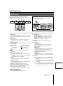
b Split-screen display
This manual was developed for two different models.
The number of camera-selection buttons on the front panel,
and the number of video input/output terminals on the rear
panel are different for these two models.
The number of split-screen fields that can be displayed is
different for each model, as shown below:
(DSR-3716PA)
(DSR-3709PA)
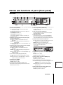
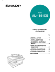
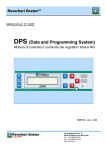
Names and functions of parts (front panel)
DSR-3716PA
1
2
3
4
5
6
7
8
9
1 Power indicator (POWER)
On: The power cord at the rear panel of the DVR is
inserted in the outlet.
Off: The power cord on the rear panel of the DVR is not
inserted in the outlet.
Fast blinking: Hard disk error.
Slow blinking: Cooling fan error.
If the indicator is blinking, contact the store where you
purchased the DVR.
2 Remaining capacity warning indicator (FULL) (P46)
(Normal recording area)
On: When recording on the hard disk has become
impossible.
Blinking: The available hard disk space dropped to the
specified level.
Off: The available disk space is reset by initialization or by
allowing overwrite.
3 Remaining alarm capacity warning indicator (ALARM
FULL ) (P46) (Alarm recording area)
On: When recording on the hard disk has become
impossible.
Blinking: The available hard disk space dropped to the
specified level.
Off: The available disk space is reset by initialization or by
allowing overwrite.
4 Lock indicator (LOCK) (P66) (Security lock)
On: The operation has been locked using the security
lock.
Off: The password of a valid administrator is entered to
release the lock (a buzzer will sound).
5 Alarm indicator (ALARM)
On: Pre-alarm recording.
Blinking: Alarm recording.
6 Function button and indicator (FUNC.) (P73)
On: Function mode (switching to dome camera control).
Off: Normal control mode.
G H IJ
7 Audio output terminal (AUDIO OUT)
The audio output is the same as that of the rear panel
AUDIO OUT terminal.
8 Video output terminal (VIDEO OUT)
The video output is the same as that of the rear panel
MAIN MONITOR OUT terminal.
9 USB terminal (USB)
This terminal connects to an optional CD-R/RW drive.
When the front panel and the rear panel terminals are
connected simultaneously, the front panel is given priority.
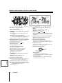
F Camera selection buttons and indicators
On: The camera is selected, or in multi-screen mode, the
indicator is on for each selected camera.
Blinking: Video-loss or an alarm detected.
When "K" is displayed in the upper right corner of the
screen a value can be input. (P33)
(DSR-3709PA)
G Quad-screen display button and indicator (QUAD)
(P15)
On: Quad-screen display.
Off: Other operation is selected.
H Monitor 2 button and indicator (MON2) (P16)
On: Monitor 2 operation.
Off: Other operation is selected.
I Plus screen button and indicator (PLUS) (P15)
On: When the image of one camera is enlarged to the size
of a quad screen as the multi screen (9/16) is
displayed.
Off: Pressing the PLUS button again will display the
previous screen.
J Multi-screen button and indicator (MULTI) (P15)
On: Multi-9 or multi-16 screen display.
Off: Other operation is selected.
Foreword
8
English
F
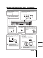
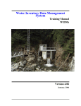
Names and functions of parts (front panel)
K L M N
Y
X
X
1 Open
2Pull out
Front
O
Q
P
2
R
Insert
3 Fold down
2 Lift and
(lock)
S T
U V
K Menu button and indicator (MENU)
On: The menu is displayed.
Off: The EXIT/OSD button is pressed.
L Exit/Operation screen display button and indicator
(EXIT/OSD)
On1: Switching from the main menu to live video or
playback.
Off: The main or other menu is displayed.
On 2: The channel or operational information is displayed
on the screen during live video or playback.
Off: The channel or operational information is hidden.
M Playback/Stop button and indicator (
PLAY/STOP)
On: Playback of video recorded on the hard disk.
Off: The playback is stopped.
N Pause button and indicator (
STILL)
On: Still image display.
Off: Still image display cancelled.
O Zoom button and indicator (ZOOM)
T Timer-controlled recording button and indicator
(TIMER)
On: Timer-controlled recording or standby.
Off: When pressed again (cancel)
U Alarm buttons (
ALARM
)
When an ALARM button is pressed during playback or still,
the digital video recorder skips to the next earlier or next
later alarm.
V Shuttle hold button and indicator (SHUTTLE HOLD)
On: The rotation angle of the shuttle dial is locked.
Off: When pressed again (cancel)
W Menu reset button (MENU RESET)
If the button is pressed after menu-setting, the items
displayed on the screen will be reset to their default values.
X CompactFlash card slot
Verify the correct orientation of the CompactFlash card or
Microdrive before inserting it into the slot.
Y Operating dials (SHUTTLE/JOG)
On: Digital zoom operation.
Off: The digital zoom operation is cancelled.
Shuttle dial
(S-dial)
P Search button and indicator (SEARCH)
On: Search for a recorded image.
Off: Exiting the search screen.
Q Automatic camera scrolling button and indicator
(SEQUENCE)
Blinking: Automatic scrolling of live video.
Off: Automatic scrolling cancelled.
R Copy button and indicator (COPY)
On: When currently copying video from the hard disk to
the archive area or other recording media.
Off: When copying operation is over and cancelled.
English
S Record/Stop button and indicator (
REC/STOP )
On: Normal recording (if pressed longer than 3 seconds,
the REC/STOP indicator turns off).
Off: Recording is over.
9
Foreword
push
W
Jog dial
(J-dial)
During playback:
• The jog dial changes the playback speed.
• The shuttle dial fast-forwards or fast-reverses playback.
During menu display:
• The jog dial moves the cursor and changes settings.
• The shuttle dial confirms settings.
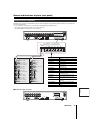
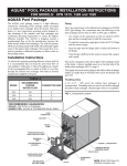
Names and functions of parts (rear panel)
Basic connections
1 Clear button (ALL RESET)
3 Video input terminal (VIDEO IN)
Press to reset the clocks connected to the digital video
recorder to their initial values.
Connect SANYO protocol cameras (dome or zoom) or generic
cameras to these terminals.
ALL
RESET
Dome camera (sold separately)
2 Video output terminal (VIDEO OUT)
To output the camera input.
1
2
3
4
5
AC IN
1
2
3
4
5
6
7
8
9
10
11
12
13
14
15
ALARM IN C 1 2 3 4 5 6 7 8 9 10 11 12 13 14 15 16
C 1 2 3
IN
AUDIO
IN
OUT
MONITOR OUT
MAIN
MON2
MIC IN
USB
ALL
RESET
LAN
A RS-485 B
RS-485
TERMINATE
OFF ON
REMOTE
SENSOR
ALARM OUT
4 5 6 7 8 9 10 11 12 13 14 15 16
OUT
REC
NON ER IN
TIM
EXIT OUT
IES
SER IES IN
SER ULL
F
RM
ALA FULL
OUT
NING
WAR R E S E T
RM
ALA M OUT
R
ALA OUT
CK
CLO CK IN
CLO
OUT
16
C R1 R2
DO NOT CONNECT TO PHONE LINE
5 Microphone input terminal
(MIC IN)
7 USB terminal (USB)
8 Power socket and cord tie
(AC IN~)
This terminal connects to an
optional CD-R/RW drive.
External microphone can be
connected to this terminal.
MIC IN
C
CONTROL
Securely connect the power cable supplied as
an accessory to the power socket, and use the
cord tie to attach it to the
cable holder.
USB
Microphone
(sold separately)
4 Audio input/output terminals (AUDIO IN/OUT)
These terminals are used in connection with an amplifier to
input external audio from a microphone, or to listen to the
audio using external speakers.
6 Monitor connection terminal (MONITOR OUT)
• Main monitor (MAIN):
Connect to this terminal for normal surveillance.
• Monitor 2 (MON2):
Connect to this terminal for convergence surveillance.
Display is possible only in full-screen mode.
MONITOR OUT
MAIN
MON2
Audio output
Audio
input
AUDIO
IN
Video input terminal
Video input terminal
OUT
01
The audio input terminal and the microphone
input terminal cannot be used for
simultaneous audio input. If both are
connected, the microphone input terminal
will be enabled.
02
03
MENU
English
Amplifier
(sold separately)
04
AUTO
MODE
POWER
Monitor (sold separately)
MENU
AUTO
MODE
POWER
Monitor (sold separately)
If monitor 2 is not synchronized with the connected
cameras, vertical image instability may occur when
switching the camera video.
Foreword
10
Names and functions of parts (rear panel)
Alarm and RS-485 connections
1 Alarm input terminals (ALARM IN)
2 Sensor alarm output terminals
(SENSOR ALARM OUT)
Connecting a switch or security sensor etc. to the terminal of the
DVR allows the detection of the intrusion of outsiders when doors
etc. are opened and closed.
Alarm input settings are necessary. (P55)
This terminal is used to output the signals listed below
whenever the motion sensor of the digital video recorder is
triggered. This output terminal can be used for a warning light
by connecting a lamp to it.
Motion sensor settings are necessary. (P58)
External switch
connected to the
alarm input terminal
16
1
Rating for each terminal:
• Maximum current: 25mA
• Maximum voltage: DC 25V
AC IN
1
2
3
4
5
6
7
8
9
10
11
12
13
14
AUDIO
IN
MODE
OUT
MIC IN
MONITOR OUT
MAIN
MON2
USB
LAN
ALL
RESET
POWER
ALARM IN C 1 2 3 4 5 6 7 8 9 10 11 12 13 14 15 16
RS-485
TERMINATE
OFF ON
A RS-485 B
SENSOR
ALARM OUT
REMOTE
4 5 6 7 8 9 10 11 12 13 14 15 16
OUT
REC
NON ER IN
TIM
EXIT OUT
IES
SER IES IN
SER ULL
F
RM
ALA FULL
OUT
NING
WAR R E S E T
RM
ALA M OUT
R
ALA OUT
CK
CLO CK IN
C LO
OUT
AUTO
16
C 1 2 3
IN
MENU
15
C R1 R2
DO NOT CONNECT TO PHONE LINE
C
CONTROL
RS-485 connection (P70)
Network connection terminals (LAN)
Use Category 5 10BASE-T/100BASE-TX LAN cables.
A Connecting directly to a PC (without using a hub)
PC
1 – 16
MENU
AUTO
MODE
POWER
Cross type
B Connecting to the intranet (using a hub)
PC
1 – 16
English
MENU
AUTO
MODE
POWER
PC
Switching hub
Straight type
Intranet
11
Foreword
Switching hub
Names and functions of parts (rear panel)
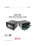
Control terminals (CONTROL)
This DVR can be remotely controlled when a remote-control circuit (R1, R2, C) similar to that shown below is connected to the
remote-control terminals.
• Use a resistance of 1/10 ohms or more and with a D ranking (Precision within ±0.5%).
• The remote control cable should be no more than 5 m long.
* The DSR-3709PA can operate up to nine cameras (*).
AC IN
1
2
3
4
5
6
7
8
9
10
11
12
13
14
15
16
ALARM IN C 1 2 3 4 5 6 7 8 9 10 11 12 13 14 15 16
C 1 2 3
IN
AUDIO
IN
OUT
MONITOR OUT
MAIN
MON2
MIC IN
USB
LAN
ALL
RESET
A RS-485 B
RS-485
TERMINATE
OFF ON
SENSOR
ALARM OUT
REMOTE
OUT
REC
NON ER IN
TIM
EXIT OUT
IES
SER IES IN
SER ULL
F
RM
ALA FULL
OUT
NING
WAR R E S E T
RM
ALA M OUT
R
ALA OUT
CK
CLO CK IN
CLO
OUT
4 5 6 7 8 9 10 11 12 13 14 15 16
C R1 R2
DO NOT CONNECT TO PHONE LINE
CONTROL
OUT
REC
NON E R I N
TIM
EXIT OUT
IES
SER S IN
E
I
SER ULL
F
RM
ALA FULL
OUT
NING
WAR RESET
RM
ALA OUT
RM
ALA OUT
CK
CLO CK IN
CLO
REMOTE
C R1 R2
R1
R2
C
C
Pin
(When operated (When combined
independently) with R2 Shift key)
SW 1 : Camera 1*: ALARM +
SW 17 : REC/STOP
SW 2 : Camera 2*: ALARM –
SW 18 : PLAY/STOP
SW 3 : Camera 3*: AUTO FOCUS
SW 19 : STILL
SW 4 : Camera 4*: SEQUENCE
SW 20 : SEARCH
SW 5 : Camera 5*: MON2
SW 21 : SHIFT (Doubles with R1)
SW 6 : Camera 6*: PLUS
SW 7 : Camera 7*: QUAD
Signal
C
Ground
REMOTE R1
Remote input 1
REMOTE R2
Remote input 2
CLOCK IN
Input of a clock setting signal from an
external device
CLOCK OUT
Output of a clock setting signal to an
external device
SW 22 : PLAY
ALARM OUT
Total alarm output
SW 23 : REC
ALARM RESET
Alarm reset input
SW 8 : Camera 8*: MULTI
SW 24 : MENU
WARNING OUT
Output of an HDD malfunction error
SW 9 : Camera 9*: MENU RESET
SW 25 : EXIT/OSD
FULL
SW 10 : Camera 10:
SW 26 : +
Capacity warning output for normal
recording area space
SW 11 : Camera 11: PAN left
SW 27 : –
ALARM FULL
SW 12 : Camera 12: PAN right
SW 28 : →
Capacity warning output for alarm
recording area space
SW 13 : Camera 13: TILT down
SW 29 : ←
SERIES IN
SW 14 : Camera 14: TILT up
SW 30 : ZOOM
Signal input from an analog series
connection
SW 15 : Camera 15: ZOOM wide
SW 31 : COPY
SERIES OUT
Signal output to an analog series
connection
SW 16 : Camera 16: ZOOM tele
SW 32 : TIMER REC
EXT TIMER IN
Signal input from an external timer
NON REC OUT
Recording stopped output
C
Ground
English
b Model DSR-3709PA (rear panel)
AC IN
1
2
3
4
5
6
7
8
ALARM IN C 1 2 3 4 5 6 7 8 9
9
C 1 2 3
IN
AUDIO
IN
ALL
RESET
OUT
MIC IN
MONITOR OUT
MAIN
MON2
USB
LAN
RS-485
TERMINATE
OFF ON
A RS-485 B
DO NOT CONNECT TO PHONE LINE
SENSOR
ALARM OUT
REMOTE
IN
IES
SER ULL
F
RM
ALA FULL
OUT
NING
WAR R E S E T
RM
ALA M OUT
R
ALA OUT
CK
CLO CK IN
C LO
OUT
4 5 6 7 8 9
C R1 R2
C
CONTROL
Foreword
12
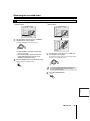
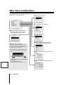
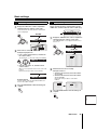
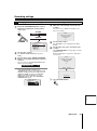
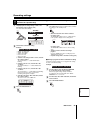
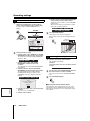
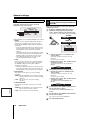
Preparing for use
Turn on the power of the DVR
1
Language, clock settings
Connect the supplied power cable.
The power indicator turns on, and the monitor displays
the "PLEASE SET THE CLOCK !" message.
The DVR performs playbacks or searches based on the
recording date and time. Select the LANGUAGE/
CLOCK SET using the INITIAL SET in the MAIN
MENU, and set the date and time using <CLOCK
SET>.
• At the same time, the recording areas of the internal
hard disk are setup automatically. When the REC/
STOP button is pressed, the device is ready for
recording.
Please refer to the "Recording area menu
description" section for more information. (P43)
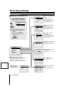
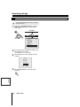
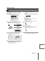
1
Press the MENU button and turn the S-dial
clockwise 3 times.
"ENGLISH" starts blinking.
MENU
<MAIN MENU>
1.INITIAL SET
2.RECORD SET
3.GENERAL SET
4.SCREEN SET
->
->
->
->
S-dial
<INITIAL SET>
1.LANGUAGE/CLOCK SET
2.CAMERA DETECT
3.TITLE SET
4.HOLIDAY SET
->
->
->
->
Archive area
S-dial
1%
Alarm
recording
area
19%
80%
Normal
recording
area
<LANGUAGE/LANGUE/SPRACHE/IDIOMA>
ENGLISH
<CLOCK SET>
01-01-2006 SUN 00:00:00
<SUMMER TIME SET>
J-dial
(Hard disk recording areas)
If the power indicator blinks when the power is turned
on or when settings are performed, this indicates that
the hard disk or the cooling fan is malfunctioning.
Refer to P5 for more information.
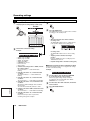
2
Language selection:
ENGLISH, FRANCAIS, DEUTSCH, ESPAÑOL
• Fast blinking: Hard disk error
• Slow blinking: Cooling fan error
2
When the time and date setting is complete, the
operation display appears on the monitor.
The operation display shows operation/related
information, such as the date, time and the operation
symbol.
Refer to "Operation display" for more information. (P14)
Turn the J-dial to select the language from the
languages displayed on the screen, and then turn
the S-dial.
The cursor moves to the date/time settings.
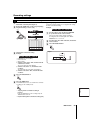
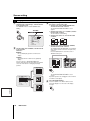
3
Turn the S-dial to set the date/time.
Example: October 26, 2006 8:30am
Select the number using the J-dial, and then turn the
S-dial clockwise to set it. Repeat the procedure for the
entire setting.
Operation display
26-10-2006 THU 08:30:00
01-01-06 00:00:00 REC REPEAT EN A ARCHIV 0001
(S)
(J)
Day
Year
Month
Hour
Seconds
Minutes
When the setting of "Minutes" is complete, the cursor
moves to <SUMMER TIME SET>, and the clock starts
from 00 seconds.
• The day of the week is automatically set.
• The clock is stopped during date/time settings.
English
4
Press the EXIT/OSD button to end the setting
procedure.
EXIT/OSD
13
How to use
Preparing for use
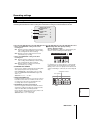
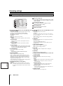
Operation display
The operation display shows information necessary for
operation, such as the date, time and video quality. The
operation display can be hidden.
1
2
3
4
56 7
Changing the position of the operation display
Whenever the EXIT/OSD button is pressed, the position of
the operation display changes.
8
EXIT/OSD
01-01-06 00:00:00 REC REPEAT EN A ALARM 0000
(Hidden)
0
02
02
02
F9
01-01-06 (day, month, year): Do not forget to set the date
using the menu settings when turning the power on for the
first time.
2 Time display
00:00:00: Do not forget to set the time using the menu
settings when turning the power on for the first time.
3 Operation symbols
The operation symbols are displayed during recording and
control operations.
: Fast-forward playback
REC: Recording
: Fast-reverse playback
EXT: External timer
recording
: Slow playback
: Reverse playback
: Reverse slow playback
: Still
: Playback (including simultaneous recording and
playback)
4 Remaining recording area (P46)
It is displayed only during normal and alarm recording.
1% ~ 100%:
If overwrite is not permitted on the hard disk, it displays
the remaining area as a percentage.
REPEAT:
Repeatedly overwrites the video on the hard disk.
5 Image quality display
The image quality display indicates the quality of the video
recorded on the hard disk.
BA (Basic): Rough image quality, approx. 15kB
NO (Normal): Standard image quality, approx. 22kB
EN (Enhanced): Enhanced image quality, approx. 30kB
FI (Fine): Fine image quality, approx. 42kB
SF (Super Fine): Super fine image quality, approx. 50kB
7 Recording type
•
•
•
•
ALARM: Alarm playback or setting is in progress
ALARM (Blinking): Alarm recording is in progress
PRE: Pre-alarm playback or setting is in progress
ARCHIV: Archive playback is in progress
8 Alarm total
The alarm total indicates the total number of alarms.
9 Camera title
• 01~16 (or 01~09):
First it displays the camera number. The camera
number can be replaced with a name such as the
camera's location.
• VIDEO LOSS:
The display alternates between this message and the
camera number when the camera video is lost.
The operating display of the monitor is not displayed
and blinks in the same position.
• NO VIDEO:
It is displayed in place of the camera number if there is
no video signal connected to the video input terminal.
F Alarm type
• EA: The display alternates between this message and
the camera title when an external alarm signal is
detected.
• SA: The display alternates between this message and
the camera title when a motion sensor alarm signal
is detected.
• ES: The display alternates between this message and
the camera title when an external alarm signal and
a motion sensor signal are detected.
6 Audio recording indicator
(P49: 2 AUDIO RECORDING)
Displayed when audio recording is performed.
How to use
14
English
1 Date display
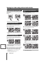
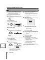
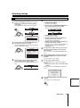
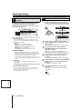
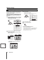
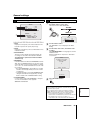
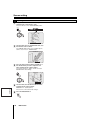
Viewing live video using various multi screens
Switching to another full-screen video
Press the camera selection button (example 2, 9) of the
desired camera.
The video from Camera 2, then the video from Camera 9 are
displayed.
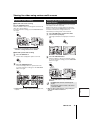
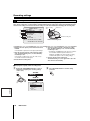
Enlarging an image in multi-screen
mode
1
PLUS
02
09
2
9
Press the PLUS button.
One camera image is displayed enlarged.
(Multi-16 mode)
01
02
03
04
05
06
07
08
09
10
11
12
09
13
14
15
16
13
03
04
07
08
10
11
12
14
15
16
01
(Multi-9 mode)
☞ Refer to P20 for enlarging the images (zoom).
Quad-screen display switching
Press the QUAD button, and then press it repeatedly.
The monitor display switches to quad-screen mode.
To return to full-screen display, press the camera selection
button of the desired camera.
2
QUAD
9
01
02
13
01
02
03
01
02
03
04
05
06
04
01 05
06
07
08
09
07
08
09
Press the camera selection button (example 9, 6).
The corresponding image is enlarged.
(Multi-16 → multi-13)
14
01
03
04
15
16
☞ DSR-3709PA: The order of quad-screen images is 1~4,
5~8, 9~3.
6
Multi-screen display switching
Press the MULTI button, and then press it repeatedly.
Multi-9 and multi-16 screens are displayed alternately.
To return to full-screen display, press the camera selection
button of the desired camera.
MULTI
01
04
07
02
05
08
03
01
02
03
04
05
06
07
08
09
10
11
12
13
14
15
16
04
07
08
09
03
04
07
08
09
10
11
12
09
10
11
12
13
14
15
16
13
14
15
16
(Multi-9 → multi-6)
01
02
03
01
02
03
04
01 05
06
04
06 05
06
07
08
09
07
08
09
Press the MULTI button to switch between split
modes.
To return to multi-screen display, press the PLUS
button.
06
09
03
MULTI
English
☞ The DSR-3709PA cannot switch to multi-16 screen.
Refer to P74 for information about rearranging the
position of the screens.
b Concerning the operation of the plus screen
• Pressing the PLUS button while playing back images
allows you to display live video and playback images
simultaneously.
• Pressing the SEQUENCE button allows you to
automatically switch the plus screen.
15
How to use
01
02
03
04
06 05
06
09
07
08
09
03
04
07
08
09
10
11
12
13
14
15
16
Note: The DSR-3709PA can display in the plus mode, but it
cannot switch split-screens.
Viewing live video using various multi screens
Automatic screen scrolling
Viewing on the monitor connected to the
MON2 terminal
A Automatic full-screen scrolling
Press the SEQUENCE button.
The live surveillance video scrolls through the cameras in the
order of the camera numbers.
To stop the automatic scrolling, press the SEQUENCE button
once again.
Connect a monitor to the MON2 terminal on the rear panel.
The display is full-screen only. (P10)
While the main monitor is used in split-screen mode, the
monitor 2 connected to the MON2 terminal can be used to
view full-screen video from a single camera or to
automatically scroll through video from all cameras.
1
SEQUENCE
Press the MON2 button, and then the camera
selection button (example 4).
The image from Monitor 2 is displayed on channel 4
(04).
4
MON 2
01
15
02
16
☞ Refer to P76 for information about setting the
automatic scrolling interval for the cameras.
B Automatic quad-screen scrolling
01
1
Press the QUAD button.
The live video is displayed in quad-screen mode.
QUAD
2
04
Press the SEQUENCE button.
Monitor 2 switches to full-screen automatic scrolling.
To stop the automatic scrolling, press the SEQUENCE
button once again.
SEQUENCE
2
Press the SEQUENCE button.
The monitor display switches to quad-screen mode.
To stop the automatic scrolling, press the SEQUENCE
button once again.
(Monitor 2)
SEQUECNE
01
15
02
01
02
13
14
03
04
15
16
16
Press the MON2 button to stop surveillance on
Monitor 2.
• The MON2 button cannot be used during menu
display.
☞ DSR-3709PA: The order of quad-screen images is 1~4,
5~8, 9~3.
☞ When an alarm is detected, the corresponding live
video can be viewed on Monitor 2.
See P60.
How to use
16
English
• Recorded video cannot be viewed on the monitor
connected to MON2.
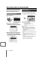
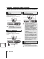
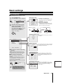
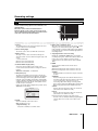
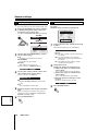
Recording video to the hard disk
The internal hard disk is automatically formatted with
recording area, normal recording, recording conditions,
etc. Before starting recording, verify the recordable
duration for normal recording. The formatting can be
modified using "Recording settings". (P39)
Normal recording
(normal recording area)
Video from all cameras connected to the video input terminals
of the DVR can be recorded with one touch of a button.
1
Recording format verification
A The total capacity of the hard disk and each area
can be verified. (P43)
Press the REC/STOP button during surveillance.
"REC" appears on the operation display, and recording
starts.
26-10-06 09:30:00 REC REPEAT EN A ARCHIV 0001
Alarm
recording
area
Archive area
1%
19%
80%
Normal recording area
<RECORDING AREA SET>
TOTAL CAPACITY
:
NORMAL RECORDING AREA
:
AREA FULL RESET ->
ALARM RECORDING AREA
:
AREA FULL RESET ->
ARCHIVE AREA
:
AREA FULL RESET ->
19 %
1 %
CAUTION : WHEN THE AREA SETTING IS CHANGED,
THE WHOLE AREA WILL BE INITIALIZED !
B The settings for recording image quality
(ENHANCED), audio recording, recording rate,
and programmed recording can be verified. (P49)
<NORMAL REC
PICTURE QUALITY
AUDIO RECORDING
REC RATE
REC PROGRAM GROUP
REC/STOP
82GB
80 %
MODE SET>
: ENHANCED
: OFF
: 12.5FPS ( 35H)
: OFF
02
2
Press the REC/STOP button for approximately 3
seconds to stop recording.
The "REC" display disappears.
• Press the PLAY/STOP button to start
playback. (P18)
• Playback is possible during recording. (P18)
b Other recordings
In addition to normal recording, the following types of
recordings can be used. These methods require some
settings and installation. Refer to the appropriate pages.
☞ Timer-controlled recording (records to the normal
recording area) P51
Automatically records the video within the preset
timeframe.
C Overwrite setting for each recording area can be
verified. If overwrite is set, and the recording
area is full, the oldest video is overwritten by
new in the order of recording. The default setting
is ON, which enables overwrite, thus provides for
continuous recording. (P47)
<RECORDING CONDITIONS SET>
NORMAL RECORDING AREA
OVERWRITE
: ON
ALARM RECORDING AREA
OVERWRITE
: ON
REMAINING DISK WARNING
SERIES RECORDING
AUTO DELETE
English
17
How to use
: **
: OFF
: OFF
☞ Alarm recording (records to the alarm recording area)
P55
Automatically records when an alarm is input from the
external alarm switch or the motion sensor.
☞ Pre-alarm recording (records to the alarm recording
area) P57
Records video and audio directly before the alarm input.
This information can be used for analyzing the
circumstances of the alarm occurrence.
☞ Motion sensor screen description P58
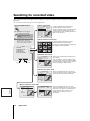
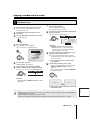
Viewing recorded video
This DVR can play video that has already been recorded or
currently being recorded in the normal recording area (by
normal or timer-controlled recording).
Normal recording area
(Normal recording area)
Full-screen viewing
1
Press the PLAY/STOP button.
Video stored in the normal recording area is played
back from the starting point of recording. The " "
symbol appears in the operation display area.
26-10-06 09:30:00 REC REPEAT EN A ARCHIV 0001
PLAY/STOP
(Hard disk recording areas)
Playback
• If the start point of the recording becomes unknown due to
deleting video or resetting, then video playback will start
from the earliest recording.
• After being paused or stopped, playback resumes from the
stop point.
02
• When playback ends, the DVR pauses automatically,
and the STILL indicator turns on. The " " symbol
appears in the operation display area.
2
Playback is possible during recording.
If the PLAY/STOP button is pressed during recording, the
video playback will begin from the start point of recording.
When playing video near the point of recording, video
playback may pause temporarily.
Press the camera selection button (example 2, 9) to
play the video of the desired camera.
PLAY/STOP
3
02
09
2
9
Press the PLAY/STOP button to end the playback.
Fast-forward/fast-reverse during
playback
Turn the S-dial clockwise for fast-forward.
The " " symbol appears in the operation display area.
26-10-06 09:30:00 REC REPEAT EN A ALARM 0000
Turn the S-dial counterclockwise for fast-reverse.
The " " symbol appears in the operation display area.
Maintaining the speed of fast-forward or fast-reverse
Press the SHUTTLE HOLD button while turning the S-dial
for fast-forward or fast-reverse.
The speed will be maintained even after the S-dial is
released.
English
26-10-06 09:30:00 REC REPEAT EN A ALARM 0000
☞ Release the S-dial for normal playback.
SHUTTLE HOLD
How to use
18
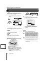
Viewing recorded video
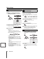
Changing the playback speed
Viewing still images
The corresponding symbol ( ,
...) appears in the
operation display area for each of these operations.
Audio will not be played when changing the playback speed.
A Fast-forward/Slow playback
Press the STILL button during playback.
The image is paused. The " " symbol appears in the
operation display area.
Press the STILL button once again, to return to normal
playback.
26-10-06 09:30:00 REC REPEAT EN A ALARM 0000
(Normal
playback)
(Fast-forward)
(Slow)
1
(Normal
playback)
2
3
STILL
02
1 Turn the J-dial clockwise.
Fast-forward playback starts.
2 Turn the J-dial counterclockwise.
Slow playback starts.
3 Turn the J-dial clockwise.
Normal playback starts.
Frame advance (forward and reverse)
Use this function while playback is paused.
• Turn the J-dial clockwise.
The still image moves forward by one frame (one
field).
B Fast-reverse/Slow-reverse playback
26-10-06 09:30:00 REC REPEAT EN A ALARM 0000
(Normal playback →
Reverse playback)
(Fast-forward)
(Slow)
(Normal
playback)
02
1
3
SHUTTLE HOLD
2
4
6
SHUTTLE HOLD
• Turn the J-dial counterclockwise.
The still image moves back by one frame (one field).
5
26-10-06 09:30:00 REC REPEAT EN A ALARM 0000
1 Turn the S-dial counterclockwise.
Normal reverse playback starts.
2 Press the SHUTTLE HOLD button.
Reverse playback speed is locked.
3 Turn the J-dial counterclockwise.
Fast-reverse playback starts.
4 Turn the J-dial clockwise.
Slow-reverse playback starts.
5 Press the SHUTTLE HOLD button.
Shuttle lock is released.
6 Turn the J-dial clockwise or counterclockwise.
Normal playback starts.
02
When the video from the normal recording area and
the alarm recording area are played back in
succession, or video is played back during alarm
recording, the following conditions may occur.
• The quality of the images of the video may
deteriorate when playback switches between
recording areas.
English
• The image may appear paused during normal
playback or fast-forward/fast-reverse.
19
How to use
Viewing recorded video
Enlarged viewing
Quad-screen viewing
The zoom function is not available in multi-screen (4/9/16),
plus screen mode or on the monitor connected to MON2.
Images become coarser during zooming.
1
Press the ZOOM button.
A zoom frame appears in the center of the screen.
Live video can be magnified during surveillance.
If video is recorded from a number of cameras, the recorded
videos can be played back in a quad-screen format.
1
Press the QUAD button during playback.
Videos recorded from camera numbers 1~4 are
displayed in quad-screen format.
2
Press the QUAD button repeatedly.
The monitor display switches to quad-screen mode.
Press the camera selection button to return to
full-screen display.
ZOOM
QUAD
2
Move the zoom frame to the area to be enlarged.
1 Turn the J-dial to move the frame horizontally.
01
02
13
14
03
04
15
16
☞ DSR-3709PA: The order of quad-screen images is 1~4,
5~8, 9~3.
2 Turn the S-dial clockwise, and then turn the
J-dial to move the frame vertically.
Multi-screen (9/16) viewing
If video is recorded from a number of cameras, the recorded
videos can be played back in a multi-screen format.
3
Turn the S-dial clockwise.
The area enclosed by the zoom frame is enlarged by a
factor of 2.
1
Press the MULTI button during playback.
Videos recorded from camera numbers 1~9 are
displayed in multi-9 format.
2
Press the MULTI button repeatedly.
The display switches between multi-16 and multi-9
modes.
Press the camera selection button to return to
full-screen display.
02
4
Press the ZOOM button to cancel the zoom
function.
01
02
03
04
05
06
07
08
09
01
02
03
04
05
06
07
08
09
10
11
12
13
14
15
16
☞ The DSR-3709PA cannot be used in multi-16 screen
mode.
☞ Refer to P74 for information about rearranging the
position of the screens.
How to use
20
English
MULTI
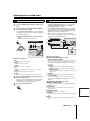
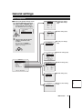
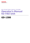
Searching for recorded video
Video stored in the normal recording area, alarm recording area or archive recording area can be located by searching and then
played back.
Use one of the five search methods to locate the required video.
Press the SEARCH button:
A Alarm search (P22)
SEARCH
The <SEARCH> screen appears.
Searching is not possible
during playback and menu
display.
Note: During playback of video, the S-dial,
the J-dial and the front panel
buttons can be used for operations
such as pause and fast-forward.
<SEARCH>
ALARM SEARCH
ALARM THUMBNAIL SEARCH
TIME/DATE SEARCH
ARCHIVE AREA SEARCH
MOTION DETECTION SEARCH
->
->
->
->
->
NO
0016
0015
0014
0013
0012
0011
0010
0009
<ALARM SEARCH>
DATE TIME CH
TOTAL ALARMS
05-01 09:53 1
00016
05-01 09:53 1
05-01 09:53 1
05-01 09:53 1
05-01 09:52 1
05-01 09:51 1
05-01 09:51 1
05-01 03:10 1
MOVE:JOG SELECT:SHUTTLE
Searches and plays alarm video from the
recording list based on date and time.
Searches and plays all video stored in the alarm
recording area. If pre-alarm video was also
recorded, then the video immediately before the
alarm can be viewed, too.
B Alarm thumbnail search (P22)
Searches and plays alarm video from the
thumbnail list based on alarm number.
0015
0014
0016
The videos recorded in the alarm recording area
are displayed in the thumbnail list.
0013
0012
0011
0010
0009
0008
C Date/time search (P23)
MOVE:JOG SELECT:SHUTTLE
J (jog) dial
S (shuttle) dial
<TIME/DATE SEARCH>
RECORDING TOP : 16-01-06 14:46
RECORDING END : 19-01-06 13:32
CHANNEL : -SEARCH :
DATE
TIME
16-01-06
14:46
PREVIEW
->
VIEW
->
Searches the recorded video period based on
date and time.
Video stored in the normal recording area (by
normal recording or timer-controlled recording)
and in the alarm recording area can be played
back by specifying the date and time.
CHANGE:JOG SET:SHUTTLE
D Archive area search (P24)
Searches and plays back video stored in the
<ARCHIVE AREA SEARCH>
archive recording area based on date and time.
NO DATE START CH
CAPACITY
0001 01-01 01:48 1
TOTAL - 816MB
Plays back video stored in the archive area.
0002 05-01 09:53 1
USED - 16MB
0003
0004
0005
0006
0007
0008
01-01 02:41
02-01 03:10
02-01 04:25
04-01 02:40
04-01 01:25
04-01 01:25
MOVE:JOG
1
1
1
1
1
1
SELECT:SHUTTLE
E Motion detection search (P24)
English
<MOTION
SEARCH FROM
START
END
DETECTION SEARCH 1>
: ALARM
: 01-01-06 00:40
: 05-01-06 10:17
CHANNEL
START PREVIEW
MOVE:JOG
21
: -->
SELECT:SHUTTLE
How to use
<MOTION DETECTION SEARCH 2>
SEARCH FROM : ALARM
/ CHANNEL : 4
START :
05-01-06 10:00
END :
05-01-06 10:17
MOTION SENSOR ->
PREVIEW
->
VIEW
->
MOVE:JOG SELECT:SHUTTLE
Searches and plays back video of moving
objects detected by motion sensors. By setting
the motion sensor back to its original location,
and specifying the date and time, motion
detections at a certain sensor can be
investigated.
Searching for recorded video
A Alarm search
B Alarm thumbnail search
1
Press the SEARCH button during recording or live
video.
1
Press the SEARCH button during recording or live
video.
2
Turn the J-dial, select "ALARM SEARCH", and turn
the S-dial clockwise.
The <ALARM SEARCH> screen is displayed.
The eight most recent alarm recordings are displayed.
2
Turn the J-dial, select "ALARM THUMBNAIL
SEARCH", and turn the S-dial clockwise.
The nine most recent alarm videos are displayed.
An alarm number is displayed for each alarm video, and
the number of the selected alarm will start blinking.
☞ Press the SEARCH button to cancel the search
☞ Press the SEARCH button to cancel the search
mode.
Operation returns to the normal screen.
SEARCH
mode.
Operation returns to the normal screen.
ALARM SEARCH
SEARCH
1
(J-dial)
(S-dial)
NO
0016
0015
0014
0013
0012
0011
0010
0009
2
DATE
05-01
05-01
05-01
05-01
05-01
05-01
05-01
05-01
3
4 5
<ALARM SEARCH>
TIME CH
TOTAL ALARMS
09:53 1
00016
09:53 1
09:53 1
09:53 1
09:52 1
09:51 1
09:51 1
03:10 1
MOVE:JOG SELECT:SHUTTLE
(Menu item - Description)
1 NO:
Displays the alarm number.
2 DATE/TIME:
Displays the date and time at which the alarm video was
recorded.
3 CH:
Displays the channel (camera number) of the alarm video.
4 TOTAL ALARMS:
Displays the total number of alarm videos recorded.
5 Preview screen:
Displays the selected alarm video.
3
ALARM THUMBNAIL SEARCH
(J-dial)
3
0015
0014
0013
0012
0011
0010
0009
0008
(S-dial)
Turn the J-dial, select the desired alarm number
(blinks), and turn the S-dial clockwise.
The selected video is played in full-screen mode. When
the selected video is over, playback pauses.
(S)
(J)
4
0016
Press the PLAY/STOP button.
PLAY/STOP
Turn the J-dial to move the cursor to the "NO" you
want to play and then turn the S-dial clockwise.
b Viewing pre-alarm video
(S)
First, the preview screen displays the video recorded at
the moment of the alarm occurrence, and then the
selected video is played in full-screen mode. When the
selected video is over, playback pauses.
4
Press the PLAY/STOP button.
• Identical to alarm searching, playback is only
possible within each individual alarm recording. Play
the previous and next alarm recordings using the
ALARM buttons.
• The S-dial, the J-dial and the front panel buttons can
be used for operations such as pause and
fast-forward.
PLAY/STOP
ALARM
How to use
22
English
(J)
After beginning playback of an alarm recording identified by
an alarm search, turn the S-dial counterclockwise.
Searching for recorded video
C Date/time search
1
Press the SEARCH button during recording or live
video.
2
Turn the J-dial, select "TIME/DATE SEARCH", and
turn the S-dial clockwise.
The cursor moves to "CHANNEL".
The cursor moves to "PREVIEW".
26-10-06
(J)
☞ Press the SEARCH button to cancel the search
mode.
Operation returns to the normal screen.
SEARCH
TIME/DATE SEARCH
1
3
(S)
(J)
4
5
2
4
<TIME/DATE SEARCH>
RECORDING TOP : 16-01-06 14:46
RECORDING END : 19-01-06 13:32
CHANNEL : -SEARCH :
DATE
TIME
16-01-06
14:46
PREVIEW
->
VIEW
->
CHANGE:JOG SET:SHUTTLE
6
(Menu item - Description)
1 RECORDING TOP/RECORDING END:
Automatically displays the date/time of the first and the last
(most recent) recorded videos. These fields cannot be
modified.
2 CHANNEL:
Used to set the channel (camera number) for playback.
3 SEARCH:
Used to set the date/time for playback.
4 PREVIEW:
When selected, displays the preview screen.
5 VIEW:
When selected, plays the previewed recording in
full-screen mode.
6 Preview screen area
3
Searching by date and time.
Example: Recording from camera 3 from 8:30pm
on October 26, 2006
12
3
<TIME/DATE SEARCH>
RECORDING TOP : 01-10-06 14:46
RECORDING END : 30-10-06 13:32
CHANNEL : 05
SEARCH :
DATE
TIME
26-10-06
20:30
PREVIEW
->
VIEW
->
English
CHANGE:JOG SET:SHUTTLE
1 Turn the S-dial clockwise.
2 Select "03" by turning the J-dial, and turn the
S-dial clockwise.
3 Select the number using the J-dial, and then turn
the S-dial clockwise to set it. Repeat the
procedure until the entire date/time setting is
complete.
23
How to use
(S)
Day
Year
20:30
Hour
Month
Minutes
Turn the S-dial clockwise.
A search progress bar is displayed during searching,
followed by recording of the specified date and time
displayed in the preview screen.
<TIME/DATE SEARCH>
RECORDING TOP : 01-10-06 14:46
RECORDING END : 30-10-06 13:32
CHANNEL : 05
SEARCH :
DATE
TIME
26-10-06
20:30
PREVIEW
->
SEARCHING
VIEW
->
CHANGE:JOG SET:SHUTTLE
☞ If no recording exists for the specified time:
The recording closest to the specified time is
displayed.
b Viewing the preview screen
Turn the J-dial, select "VIEW", and turn the S-dial
clockwise.
The selected video is played in full-screen mode.
If a date/time search is performed on alarm recordings
or programmed recordings by specifying the channel,
depending on the recording circumstances, the
desired video may not be found. In this case, try the
date/time search again without specifying the channel.
Start playback, and use fast-forward and fast-reverse
to locate the video from the desired channel.
Note: • The retrieved video can be displayed in full-screen mode
without displaying the preview screen by entering the date
and the time and by selecting "VIEW".
• The S-dial, the J-dial and the front panel buttons can be
used for operations such as pause and fast-forward.
• If "CHANNEL" is set to "--", then playback will be displayed
in multi-screen mode.
Searching for recorded video
E Motion detection search
Plays back video stored in the archive area.
1
Press the SEARCH button during recording or live
video.
2
Turn the J-dial, select "ARCHIVE AREA SEARCH",
and turn the S-dial clockwise.
The <ARCHIVE AREA SEARCH> screen is displayed.
The eight most recent archive recordings are displayed
in the order of archiving.
☞ Press the SEARCH button to cancel the search
mode.
Operation returns to the normal screen.
SEARCH
• Select the search area and the channel number on the
<MOTION DETECTION SEARCH 1> screen. Selecting
the <START PREVIEW> will display the <MOTION
DETECTION SEARCH 2> screen.
• The <MOTION DETECTION SEARCH 2> screen displays
the specified search area and channel number. Set the
start and end date/time, and select "MOTION SENSOR" to
display the motion sensor setting screen.
• On the motion sensor setting screen, set the motion
sensor for the recorded images and detect scenes where
images were changed by intruders etc.
1
ARCHIVE AREA SEARCH
1 2 34
56
2
3
<MOTION
SEARCH FROM
START
END
DETECTION SEARCH 1>
: ALARM
: 01-01-06 00:40
: 05-01-06 10:17
CHANNEL
: --
START PREVIEW
MOVE:JOG
(J)
(S)
NO
0001
0002
0003
0004
0005
0006
0007
0008
<ARCHIVE AREA SEARCH>
DATE START CH
CAPACITY
01-01 01:48 1
TOTAL - 816MB
05-01 09:53 1
USED - 16MB
01-01 02:41 1
02-01 03:10 1
02-01 04:25 1
04-01 02:40 1
04-01 01:25 1
04-01 01:25 1
MOVE:JOG SELECT:SHUTTLE
(Menu item - Description)
1 NO:
Displays the number of the archive.
2 DATE:
Displays the date of recording.
3 START:
Displays the start time of recording.
4 CH:
Displays the lead channel (camera number) of the recording.
5 TOTAL:
Displays the total capacity of the archive area.
6 USED:
Displays the amount of the archive area that has been used.
3
4
Select the desired "NO" by turning the J-dial, and
turn the S-dial clockwise.
The selected video is displayed in the preview screen,
and playback starts in full-screen mode. When the
selected video is over, playback pauses.
Press the PLAY/STOP button.
PLAY/STOP
->
SELECT:SHUTTLE
1
2
3
4
5
<MOTION DETECTION SEARCH 2>
SEARCH FROM : ALARM
/ CHANNEL : 4
START :
05-01-06 10:00
END :
05-01-06 10:17
MOTION SENSOR ->
PREVIEW
->
VIEW
->
MOVE:JOG SELECT:SHUTTLE
-
-
-
-
-
-
-
-
LEVEL : OFF
-
-
-
-
EXIT
(Menu item - Description)
<MOTION DETECTION SEARCH 1> screen
1 SEARCH FROM/START/END
When selecting a recording area for the motion sensor setting, the
date and time of the first and last recording in the selected
recording area will be displayed automatically. These fields cannot
be modified.
Selections:
• ALARM: Searches video from the alarm recording area.
• NORMAL: Searches video from the normal recording area.
• ALARM & NORMAL:
Searches video from the alarm recording area and the normal
recording area.
2 CHANNEL
Use this menu item to selects the channel for the motion sensor.
3 START PREVIEW
Search is performed based on the above selected area and
channel and the <MOTION DETECTION SEARCH 2> screen is
displayed.
<MOTION DETECTION SEARCH 2> screen
1 SEARCH FROM/CHANNEL
Displays the settings selected on the <MOTION DETECTION
SEARCH 2> screen.
2 START/END
Used to set the start and end time of the search area and
specified channel.
English
D Archive area search
3 MOTION SENSOR
Displays the motion sensor setting screen.
4 PREVIEW
The video found by the search function is displayed in the preview
area.
5 VIEW
The video found by the search function is played in full-screen
mode.
How to use
24
Searching for recorded video
E Motion detection search (continued)
1
Press the SEARCH button during recording or live
video.
2
Turn the J-dial, select "MOTION DETECTION
SEARCH", and turn the S-dial clockwise.
The <MOTION DETECTION SEARCH 1> screen
appears.
The "SEARCHING" starts blinking.
☞ Press the SEARCH button to cancel the search
mode.
Operation returns to the normal screen.
SEARCH
9
Example: November 29, 2006 8:30pm
The cursor moves to the MOTION SENSOR field.
END :
29-11-06
À
<MOTION
SEARCH FROM
START
END
(S)
(J)
3
Turn the S-dial clockwise.
The "ALARM" starts blinking.
4
Select the desired recording area (example: ALARM
& NORMAL) by turning the J-dial, and then turn the
S-dial clockwise.
"SEARCHING" of END starts blinking again, the search
is over.
CHANNEL
Turn the S-dial clockwise.
The motion sensor setting screen is displayed.
START :
28-10-06 20:30
END :
29-11-06 20:30
MOTION SENSOR ->
PREVIEW
->
VIEW
->
MOVE:JOG SELECT:SHUTTLE
: SEARCHING
DETECTION SEARCH 1>
: ALARM
: 01-01-06 00:40
: 05-01-06 10:17
Á
: --
6
8
Turn the S-dial clockwise, and set the number using
the J-dial. Turn the S-dial clockwise again, and
repeat this to set the date and time for the start of
the search.
English
Turn the S-dial clockwise.
The screen switches to the <MOTION DETECTION
SEARCH 2> screen, and the channel 4 preview screen
is displayed.
Example: October 28, 2006 8:30pm
When the settings are complete, turn the S-dial
clockwise.
START :
28-10-06
20:30
How to use
-
-
-
-
LEVEL : OFF
-
-
-
-
EXIT
(S)
-
-
-
-
-
-
-
-
-
-
-
-
-
-
EXIT
2 Turn the J-dial to move the cursor to "LEVEL:
OFF", and then turn the S-dial clockwise.
The "OFF" starts blinking.
Selections: OFF/1/2/.../9/10 (low sensitivity)
3 Turn the J-dial to set "LEVEL: OFF" to [5], and
then turn the S-dial clockwise twice.
The <MOTION DETECTION SEARCH 2> screen
returns.
For searching the "PREVIEW" or "VIEW" screens,
continue at P26 without exiting the current search.
->
7
-
LEVEL : 5
Select the desired channel (example: camera 4) by
turning the J-dial, and then turn the S-dial
clockwise.
The cursor moves to the START PREVIEW field.
START PREVIEW
25
(J)
Select a channel by turning the J-dial and then turn
the S-dial clockwise.
The "– –" starts blinking.
-
Setting the motion sensor
1 Turn the J-dial to move the cursor to the desired
position of the sensor, and then turn the S-dial
clockwise.
–: Sensor is not set
ú: Sensor is set
After switching the sensor from unset to set, the
same operation can be used to set sensors at other
locations.
Selections: ALARM/NORMAL/ALARM & NORMAL
5
20:30
<MOTION DETECTION SEARCH 2>
SEARCH FROM : ALARM & NORMAL/ CHANNEL : 4
MOTION DETECTION SEARCH
END
Repeat the same steps as shown at 8 to set the
end date and time for the search.
Â
Press the SEARCH button to exit the search mode.
The normal live video display returns.
SEARCH
If you set the motion search to a specific channel
(camera number), only the video from the specified
channel will be played. The camera title, date and time
may not be displayed fully on the screen.
Searching for recorded video
E Motion detection search (continued)
b Motion sensor settings verification using the
preview screen
b Full-screen viewing of video detected by the
motion sensor
<MOTION DETECTION SEARCH 2>
SEARCH FROM : ALARM
/ CHANNEL : 4
<MOTION DETECTION SEARCH 2>
SEARCH FROM : ALARM
/ CHANNEL : 4
START :
05-01-06 10:00
END :
05-01-06 20:00
MOTION SENSOR ->
PREVIEW
->
VIEW
->
MOVE:JOG SELECT:SHUTTLE
1
START :
05-01-06 10:00
END :
05-01-06 20:00
MOTION SENSOR ->
PREVIEW
->
VIEW
->
MOVE:JOG SELECT:SHUTTLE
Turn the J-dial to move the cursor to "PREVIEW",
and then turn the S-dial clockwise.
The image is displayed in the preview area.
(S)
(J)
☞ If "NOT FOUND" is displayed, set the motion
sensors once again.
☞ Each time the S-dial is turned clockwise, the
1
images detected by the motion sensor are
displayed on the preview screen.
Press the SEARCH button to exit the search mode.
The normal live video display returns.
SEARCH
(J)
(S)
To search a recording from a different channel, stop
the current playback and then repeat the setting
process from the beginning.
2
Press the PLAY/STOP button.
PLAY/STOP
English
2
Turn the J-dial to move the cursor to "VIEW", and
then turn the S-dial clockwise.
Normal playback starts from the selected image. When
the video is over, playback pauses.
How to use
26
Copying recorded video to media
Selected video stored in the normal recording area and the alarm recording area can be copied to various media (full
screen). Images copied to a CompactFlash card can be directly printed on a printer.
Copying video from the normal or
A alarm recording area to the archive
area (P28)
Copying video from the internal hard
C disk to media such as a
CompactFlash card (P30)
Archive area
We recommend using this area to store video only for quick
verification, not as a permanent storage.
If complete archival is required, copy to media such as a
CompactFlash card.
Archive area
Alarm recording area
Alarm recording area
Normal recording area
• Verify the available recording space in the archive
area before copying.
• If the available archive area is insufficient, copy the
archive area to media such as a CompactFlash card,
and erase the archive area.
Copying video from the internal hard
disk to the CD-R/RW (P29)
B
Normal
recording area
Before copying, connect the CD-R/RW drive to the USB
connector on the front or the rear panel.
If the CD-R/RW drive connection is not confirmed the
selections of the CD-R/RW under the COPY TO are not
displayed.
Archive area
Alarm recording area
Normal recording area
• When video is being copied from the normal or the
alarm recording area to media such as a
CompactFlash card, the video is temporarily stored
in the archive area, and then copied to the media.
Always check for sufficient archive space before
copying. When the copying is complete, the video
will be deleted from the archive area.
• Copying video to a CompactFlash card takes about
15 seconds per 1MB. If the recording capacity
becomes full during the copying operation, the
message "COMPACTFLASH FULL!" appears and the
copying operation finishes. Press any key to return
to the normal screen. Repeat the copy procedure
with a CompactFlash card that has sufficient
recording space.
• Video copied to a CompactFlash card or CD-R/RW
includes a tampering detection code. Contact the
store where you purchased your device regarding
the detection of tampering occurrences.
• Video copied to a CompactFlash card or CD-R/RW
with audio attached can be played using the DVR
Viewer 2. Refer to the separate "Manual for Remote
Operation using a Network Connection" for more
information.
• JPEG images are handled as field images. Viewing
these images using an image processing software
available on the market will result in viewing the
vertical direction compressed to 50% so please
make sure to use DVR Viewer 2.
Printing images directly from the
D CompactFlash card or the microdrive.
(P31)
English
In order to print the recorded images, the media must be
formatted on the DVR before use.
Only FAT16 CompactFlash cards can be formatted on
the DVR. The DVR will not recognize FAT32 cards.
27
How to use
Copying recorded video to media
A
Copying video (example: 10 seconds) from the normal or alarm recording area to the
archive area
1
Start playback from the normal or alarm recording
area.
2
Press the STILL button at the image to be copied.
The image is paused.
7
Turn the J-dial to select "SECONDS", and then turn
the S-dial clockwise.
The cursor moves to "COPY START".
HOW MANY :
10 SECONDS
STILL
COPY CH
Press the COPY button.
The copy setting screen is displayed.
The cursor moves to the "COPY TO" field.
Selections:
PICTURES:
Copies the specified number of images.
SECONDS:
Copies the specified duration in seconds.
MINUTES:
Copies the specified duration in minutes.
COPY
COPY TO : ARCHIVE AREA
HOW MANY : 1 PICTURES
COPY CH
01 02 03 04 05 06 07 08
09 10 11 12 13 14 15 16
SELECT COPY CHANNEL
COPY START ->
FORMAT/ERASE: COMPACT FLASH
FORMAT/ERASE START ->
8
(S)
4
Turn the S-dial clockwise.
"ARCHIVE AREA" starts blinking.
5
Turn the J-dial to select COPY TO "ARCHIVE
AREA", and then turn the S-dial twice clockwise.
The cursor moves to the 1 of the "HOW MANY" field.
COPY TO :
(J)
☞ Press the COPY button to cancel the current
ARCHIVE AREA
copy operation.
9
Turn the S-dial clockwise to start copying.
• Copying to the archive area starts, and the "COPY
TO ARCHIVE AREA !" message is displayed.
• When copying is complete, the "COPY FINISHED !"
message is displayed.
(S)
Selections:
ARCHIVE AREA, COMPACT FLASH, CF→PRINT,
CD-R/RW
6
Select the channel to be copied (Example: 03, 05)
using the camera selection button.
The selected channel changes from grey to white.
• The default channel is green. The channel in green
can not be modified.
Turn the J-dial to select HOW MANY "10", and then
turn the S-dial clockwise.
The "PICTURES" starts blinking.
HOW MANY:
(S)
COPY TO ARCHIVE AREA ! < 55% >
COPY FINISHED !
< 100% >
10 PICTURES
Select a value between 1~99.
Even if a video with audio attached is copied to the
archive area only the images are copied.
English
3
01 02 03 04 05 06 07 08
09 10 11 12 13 14 15 16
SELECT COPY CHANNEL
COPY START ->
How to use
28
Copying recorded video to media
B Copying video (example: 10 pictures) from the internal hard disk to the CD-R/RW drive
1
Connect the optional CD-R/RW drive to the USB
connector on the front or rear panel of the DVR.
If the front and the rear USB terminal are connected
simultaneously the front is given priority.
2
Start playback from the normal, alarm or the
archive area.
3
Press the STILL button at the image to be copied.
The image is paused.
9
☞ Press the COPY button to cancel the current
copy operation.
À
STILL
4
Select the channel to be copied (Example: 03, 05)
using the camera selection button.
The selected channel changes from grey to white.
• The default channel is green. The channel in green
can not be modified.
Turning the S-dial clockwise displays the CD-R/RW
writing confirm screen.
The cursor moves to "FINALIZE".
COPY TO
HOW MANY
FINALIZE :
VERIFY :
START
Press the COPY button.
The copy setting screen is displayed.
The cursor moves to the "COPY TO" field.
CD-R/RW
1 PICTURES
ON
OFF
->
COPY
(S)
COPY TO : ARCHIVE AREA
HOW MANY : 1 PICTURES
COPY CH
01 02 03 04 05 06 07 08
09 10 11 12 13 14 15 16
SELECT COPY CHANNEL
COPY START ->
5
Turn the S-dial clockwise.
"ARCHIVE AREA" starts blinking.
6
Turn the J-dial to select COPY TO "CD-R/RW", and
then turn the S-dial twice clockwise.
The cursor moves to the 1 of the "HOW MANY" field.
COPY TO : CD-R/RW
(J)
(S)
HOW MANY :
Turn the S-dial clockwise, select the FINALIZE
settings using the J-dial and turn the S-dial
clockwise.
ON: Finalizes the disc. Once the disc is finalized the
disc is not recordable.
OFF: The disc is not finalized. The disc recording can
be interrupted.
The cursor moves to "VERIFY".
Â
Turn the S-dial clockwise, select the VERIFY setting
using the J-dial and turn the S-dial clockwise.
ON: The writing status is verified once the disc writing
is complete.
OFF: The disc writing status is not verified once the
disc writing is complete.
The cursor moves to "START→".
Ã
Turn the S-dial clockwise.
Copying to CD-R/RW starts and the following
messages are displayed during the copying operation.
↓ COPY TO CD-R/RW ! <----> → <0%> → <100%>
↓ (If FINALIZE is set to OFF)
CLOSING CD-R/RW ! PLEASE WAIT
↓ (If FINALIZE is set to ON)
FINALIZING CD-R/RW ! PLEASE WAIT
↓ COPY FINISHED ! < 100% >
1 PICTURES
Selections:
ARCHIVE AREA, COMPACT FLASH, CF→PRINT,
CD-R/RW
7
Turn the J-dial to select HOW MANY "10", and then
turn the S-dial clockwise.
The "PICTURES" starts blinking.
Select a value between 1~99, >99.
8
Turn the J-dial to select "SECONDS", and then turn
the S-dial clockwise.
The cursor moves to "COPY START".
HOW MANY :
Á
10 SECONDS
English
If a new disk (CD-RW) or an erasable disc is used for
the copying, format the disc before use.
COPY CH
01 02 03 04 05 06 07 08
09 10 11 12 13 14 15 16
SELECT COPY CHANNEL
COPY START ->
Selections:
PICTURES, SECONDS, MINUTES, EVENTS
• EVENTS allows you to copy the data of the
archive area per event. Selecting >99 fills the
capacity regardless of the event.
29
How to use
Copying recorded video to media
C
Copying video (example: 10 pictures) from the internal hard disk to media such as a
CompactFlash card
Copy to a MicroDrive is also possible, up to 2GB.
1
Insert the card into the CompactFlash card slot.
Refer to the names and functions of parts when
inserting the card. (P9)
2
Start playback from the normal, alarm or the
archive area.
3
Press the STILL button at the image to be copied.
The image is paused.
7
Turn the J-dial to select HOW MANY "10", and then
turn the S-dial clockwise.
The "PICTURES" starts blinking.
Select a value between 1~99, >99.
8
Turn the J-dial to select "PICTURES", and then turn
the S-dial clockwise.
The cursor moves to "COPY START–>".
HOW MANY :
10 PICTURES
STILL
COPY CH
01 02 03 04 05 06 07 08
09 10 11 12 13 14 15 16
SELECT COPY CHANNEL
CPPY START ->
4
Press the COPY button.
The copy setting screen is displayed.
The cursor moves to the "COPY TO" field.
Selections:
PICTURES, SECONDS, MINUTES, EVENTS
• EVENTS allows you to copy the data of the
archive area per event. Selecting >99 fills the
capacity regardless of the event.
COPY
COPY TO : ARCHIVE AREA
HOW MANY : 1 PICTURES
COPY CH
01 02 03 04 05 06 07 08
09 10 11 12 13 14 15 16
SELECT COPY CHANNEL
COPY START ->
9
FORMAT/ERASE: COMPACT FLASH
FORMAT/ERASE START ->
(S)
Select the channel to be copied (Example: 03, 05)
using the camera selection button.
The selected channel changes from grey to white.
• The default channel is green. The channel in green
can not be modified.
☞ Press the COPY button to cancel the current
copy operation.
5
Turn the S-dial clockwise.
"ARCHIVE AREA" starts blinking.
6
Turn the J-dial to select COPY TO "COMPACT
FLASH", and then turn the S-dial twice clockwise.
The cursor moves to the 1 of the "HOW MANY" field.
À
COPY TO : COMPACT FLASH
(J)
(S)
HOW MANY :
Turn the S-dial clockwise to start copying.
• Copying to the CompactFlash card starts, and the
"COPY TO COMPACT FLASH!" message is
displayed.
• When copying is complete, the "COPY FINISHED!"
message is displayed.
1 PICTURES
(S)
Selections:
ARCHIVE AREA, COMPACT FLASH, CF→PRINT,
CD-R/RW
COPY TO COMPACT FLASH ! < 55% >
COPY FINISHED !
< 100% >
☞ Refer to P32 for viewing the images copied to the
• Maximum 40,000 images can be copied in a single copy operation. If the length of copying was specified using "MINUTES",
copying will end at 40,000 images.
• Alarm recordings can only be copied one event at a time.
• Format the CompactFlash card (FAT16) using this equipment. Formats done using FAT 32 will not be recognized.
How to use
30
English
CompactFlash card.
Copying recorded video to media
D Printing images directly from the CompactFlash card or the microdrive
1
Insert the card into the CompactFlash card slot.
Refer to the names and functions of parts when
inserting the card. (P9)
2
Start playback from the normal, alarm or the
archive area.
3
Press the STILL button at the image to be printed.
The image is paused.
7
HOW MANY:
8
STILL
4
COPY
COPY TO : ARCHIVE AREA
HOW MANY : 1 PICTURES
COPY CH
01 02 03 04 05 06 07 08
09 10 11 12 13 14 15 16
SELECT COPY CHANNEL
COPY START ->
5
Turn the S-dial clockwise.
"ARCHIVE AREA" starts blinking.
6
Turn the J-dial to select COPY TO "CF→PRINT",
and then turn the S-dial twice clockwise.
The cursor moves to the 1 of the "HOW MANY" field.
COPY TO : CF->PRINT
10 PICTURES
Turn the J-dial to select "PICTURES", and then turn
the S-dial clockwise.
The cursor moves to "COPY START".
Selections:
PICTURES:
Prints the specified number of images.
SECONDS:
Prints the images of the specified duration in
seconds.
MINUTES:
Prints the images of the specified duration in
minutes.
EVENTS:
Prints the archive area data specified in units of
events. Maximum 99 events can be specified.
Press the COPY button.
The copy setting screen is displayed.
The cursor moves to the "COPY TO" field.
(S)
Turn the J-dial to select HOW MANY "10", and then
turn the S-dial clockwise.
The "PICTURES" starts blinking.
9
Turn the S-dial clockwise.
A folder named "DCIM" is created under the root
directory, followed by a sub-folder with the date of the
copied images.
CompactFlash card
DCIM
100_0406
101_0406
00000001.JPG
00000002.JPG
00000003.JPG
102_0406
(J)
(S)
☞ Use the EXIT/OSD button to switch the position
Selections:
ARCHIVE AREA, COMPACT FLASH, CF→PRINT,
CD-R/RW
of the date or to hide it for printing. (P14)
• Maximum 999 images can be printed in a single printing operation. Even if 10-minutes duration is selected, printing will end
at 999 images.
• If "CF→PRINT" is selected, the time necessary to copy is about twice as long as (1MB per 30 seconds) when "COMPACT
FLASH" is selected.
• Use the SANYO DVP-P1 Digital Photo Printer. Operation is not guaranteed if using another printer.
English
31
How to use
Copying recorded video to media
CompactFlash cards or CD-RW formats
b CompactFlash format
• If no CD-R/RW driver is connected to the USB terminal,
the format of the CompactFlash is given priority.
• The microdrive can be formatted in the same way.
1
Insert the CompactFlash in the CompactFlash card
slot.
2
Press the PLAY/STOP button, the STILL button, and
the COPY button.
The COPY TO screen is displayed.
Viewing Images copied to a
CompactFlash card on a PC
Copying video to a CompactFlash and a CD-R/RW creates
the following folders and saves the images.
With a CompactFlash
1st layer
2nd layer
3rd layer
SANYO
_VIEWER
IJL15.DLL
J2KCOREX.DLL
VIEWER2.EXE
VIEWER2.INI
IMG00001
00000001.JPG
IMG00002
00000200.JPG
00000201.JPG
IMG00200
00000400.JPG
00039801.JPG
SOUND
INFO
IMG00001
00040000.JPG
SOUND.WAV
DDMMYY01.INF
00000001.JPG
IMG00002
00000200.JPG
00000201.JPG
IMG00200
00000400.JPG
00039801.JPG
SOUND
INFO
00040000.JPG
SOUND.WAV
DDMMYY02.INF
DDMMYY01
COPY TO : ARCHIVE AREA
HOW MANY : 1 PICTURES
COPY CH
01 02 03 04 05 06 07 08
09 10 11 12 13 14 15 16
SELECT COPY CHANNEL
COPY START ->
FORMAT/ERASE: COMPACT FLASH
FORMAT/ERASE START ->
2
DDM M YY
Year
Month
Day
Move the cursor to "FORMAT/ERASE START" on
the last row by turning the J-dial and then turn the
S-dial clockwise.
Formatting (initializing) starts.
With a CD-R/RW
1st layer
b CD-RW format
1
DDMMYY02
Connect the CD-RW driver to the USB terminal and
insert a CD-RW disc.
If the front and the rear USB terminal are connected
simultaneously the front is given priority.
SANYO
AUTORUN.INF
IJL15.DLL
J2KCOREX.DLL
VIEWER2.EXE
VIEWER2.INI
Move the cursor to "FORMAT/ERASE" by turning
the J-dial and turn the S-dial clockwise.
"COMPACT FLASH" blinks.
2nd layer
DDMMYY01
One data
saving
DDMMYY02
DDM M YY
COPY TO : ARCHIVE AREA
HOW MANY : 1 PICTURES
COPY CH
01 02 03 04 05 06 07 08
09 10 11 12 13 14 15 16
SELECT COPY CHANNEL
COPY START ->
FORMAT/ERASE: CD-RW
FORMAT/ERASE START ->
3
Year
Month
Day
3rd layer
4th layer
IMG00001
00000001.JPG
IMG00002
00000200.JPG
00000201.JPG
IMG00200
00000400.JPG
00039801.JPG
SOUND
INFO
00040000.JPG
SOUND.WAV
DDMMYY01.INF
IMG00001
00000001.JPG
IMG00002
00000200.JPG
00000201.JPG
IMG00200
00000400.JPG
00039801.JPG
SOUND
INFO
00040000.JPG
SOUND.WAV
DDMMYY02.INF
• Each image folder contains 200 images. If the number of
images exceeds 200 they are placed in the next folder.
• A SOUND.WAV file is created in the SOUND folder.
Select "CD-RW" by turning the J-dial and then turn
the S-dial twice clockwise.
Formatting (initializing) starts.
English
3
One data
saving
4th layer
How to use
32
Main menu configuration
The main menu consists of seven items, and can be
displayed by pressing the MENU button.
b Default value settings (P34)
<INITIAL SET>
1.LANGUAGE/CLOCK SET
2.CAMERA DETECT
3.TITLE SET
4.HOLIDAY SET
5.TIME PERIOD SET
<MAIN MENU>
1.INITIAL SET
2.RECORD SET
3.GENERAL SET
4.SCREEN SET
5.POWER LOSS/USED TIME
6.INITIALIZATION LOG
7.COPY MENU SETTINGS
MOVE:JOG
->
->
->
->
->
->
->
MOVE:JOG
->
->
->
->
->
SELECT:SHUTTLE
b Recording and alarm settings (P39)
SELECT:SHUTTLE
b Copy the contents of the menu settings of
this DVR and operate another unit of the
same model with the same menu (P82)
<RECORD SET>
1.NORMAL REC EASY SET
2.RECORDING AREA SET
3.RECORDING CONDITIONS SET
4.NORMAL REC MODE SET
5.PROGRAM REC SET
6.TIMER SET
7.ALARM REC MODE SET
8.ALARM OPERATION SET
MOVE:JOG
->
->
->
->
->
->
->
->
SELECT:SHUTTLE
b Generic settings (P62)
<COPY MENU SETTINGS>
<GENERAL SET>
1.DISPLAY SET
2.BUZZER SET
3.SECURITY LOCK SET
4.HDD SET
5.NETWORK SET
6.RS-485 SET
7.CAMERA CONTROL SET
DVR TYPE VER. SA16-04
SAVE MENUS TO CF
->
LOAD MENUS FROM CF
->
COPY RECORDING AREA SETTINGS: NO
*IF YOU CHOOSE 'YES' OF THE ABOVE MENU,
HARD DISK WILL BE INITIALIZED !
MOVE:JOG
b Entering numbers using buttons
Normally, numeric values and channels (camera
numbers) are set using the J-dial, but camera
selection buttons and the QUAD button on the front
panel can also be used for settings.
A value can be input using the button below when
"K" is displayed on the upper right corner of the
screen.
->
->
->
->
->
->
->
SELECT:SHUTTLE
b Special settings (display shunt, automatic
scrolling, masking, tone adjustment) (P74)
<SCREEN SET>
1.MULTI SCREEN
: NORMAL
QUAD POSITION SET
->
MULTI 9 POSITION SET
->
MULTI 16 POSITION SET ->
2.SEQUENCE
: 1SEC
SEQUENCE SET
->
MAIN/MON.2 MONITOR SET ->
3.MASK
: OFF
MASK SET
->
4.COLOR LEVEL SET
->
b Power outage time, hard disk's hours of use, etc.
(P80)
K
1
=
2
3
4
5
6
7
8
QUAD
9
10
English
• Camera selection button 10 and QUAD button:
0 is displayed.
• Camera selection buttons 1~9:
Displays the number of the button pressed.
<POWER LOSS/USED TIME>
POWER
LOSS
RECOVER
#011
14-01 19:15 14-01 09:55
05-01 21:13 14-01 09:21
03-01 18:48 05-01 08:56
01-01 09:49 03-01 10:32
USED TIME
DISK1 USE : 00096H
DISK2 USE : -----H
POWER
: 00096H
F/W : M 1.00-00 / S 1.00-00
b Hard disk initialization, initialization log display
(P81)
DATE
26-10
26-10
26-10
26-10
26-10
26-10
26-10
-----
33
How to set
<INITIALIZATION LOG>
TIME
AREA
18:25
ALL AREAS (INITIALIZED)
23:18
ALL AREAS (INITIALIZED)
23:18
ARCHIVE
(AREA RESET)
23:18
ALARM REC (AREA RESET)
23:18
NORMAL REC (AREA RESET)
23:16
ALL AREAS (INITIALIZED)
23:15
ALL AREAS (INITIALIZED)
--:------(------)
Basic settings
Menu configuration
b Displaying the basic settings screen
1
Press the MENU button.
The <MAIN MENU> screen is displayed.
MENU
<MAIN MENU>
1.INITIAL SET
2.RECORD SET
3.GENERAL SET
4.SCREEN SET
2
->
->
->
->
Turn the S-dial clockwise, turn the
J-dial to select the menu and then
turn the S-dial clockwise
The <INITIAL SET> screen is displayed.
The selected screen (A~E) is
displayed. Refer to the appropriate
pages for the settings.
A Language setting
<LANGUAGE/LANGUE/SPRACHE/IDIOMA>
ENGLISH
<CLOCK SET>
01-01-2006 SUN 00:00:00
<SUMMER TIME SET>
MODE
:
USE
WEEK MONTH TIME
ON
LST-SUN
03
02:00
OFF LST-SUN
10
02:00
<EXT.CLOCK SET>
ADJUST. TIME
01:00
(Figure 1)
(Clock setting
output terminal)
☞ Language, Clock setting (P13)
Sets the date and time for displaying on the
normal screen. Refer to the "Preparing for
use" section.
Summer time setting (P35)
☞
☞ External clock setting (P35)
If multiple devices are connected, they can
be synchronized to the same clock. Refer to
Figure 1 for the proper connections.
(C terminal)
First
DVR unit
(Clock setting input terminal)
Second
DVR unit
To connect a
third DVR unit
B Camera detection (P35)
(S)
Automatically detects the cameras connected
to the DVR.
<WARNING>
CAMERA DETECT
<INITIAL SET>
1.LANGUAGE/CLOCK SET
2.CAMERA DETECT
3.TITLE SET
4.HOLIDAY SET
5.TIME PERIOD SET
CONTINUE?
NO
->
->
->
->
->
C Title setting (P36)
Sets a unique title for each camera, for example
the name of the location it is placed. The titles
are displayed on the monitor.
<TITLE SET>
CAMERA NO.01 ---------01
MOVE:JOG
SELECT:SHUTTLE
b Menu changes disabled display during
recording
b Menu changes allowed display
Interrupt the recording, the main menu can be
modified.
Pressing the SHUTTLE HOLD button for approx. 3
seconds will display <- -> on the far left of the
screen, the menu can be modified.
Once the menu is complete the DVR automatically
returns to recording.
SHUTTLE HOLD
<MAIN MENU>
1.INITIAL SET
2.RECORD SET
->
->
If a recording is being cancelled, a
new recording cannot be received.
Similarly, in the event of power failure
recording cannot be restored.
D Holiday setting (P36)
1.
2.
3.
4.
5.
6.
7.
8.
9.
10.
<HOLIDAY
-----------------------------------------
SET>
11.
12.
13.
14.
15.
16.
17.
18.
19.
20.
-----------------------------------------
Sets the specified days as holidays. Public
holidays, company holidays can also be set for
timer-controlled operation identical to that of
Sundays.
E Time period setting (P37)
<TIME PERIOD SET>
TIME PERIOD
T-1
T-2
T-3
T-4
TIME PERIOD A 00:00 00:00 00:00 00:00
TIME PERIOD B 00:00 00:00 00:00 00:00
SELECT TIME PERIOD
SEQUENCE
MASK
MOTION SENSOR
For example, TIME PERIOD A can be set for
automatic scrolling display, and TIME PERIOD
B can be set for gray pattern masking of
camera images.
TIME PERIOD A
TIME PERIOD A
TIME PERIOD A
How to set
34
English
If <a> is displayed on the far left of the screen
when the main menu is displayed while the DVR is
recording, the main menu can not be modified.
Basic settings
A Summer time setting
A-1
Automatic switching from standard time to summer time
can be set.
1
Display the <LANGUAGE/LANGUE/SPRACHE/
IDIOMA> screen as explained in "Displaying the
basic settings screen" (P34).
<MAIN MENU>
1.INITIAL SET
MENU
External clock setting
(EXT. CLOCK SET)
Connect the CLOCK OUT terminal of the CONTROL
terminal block on the rear panel of the DVR to the CLOCK
IN terminal of the second DVR (P34: Figure 1), and move
the cursor to <EXT. CLOCK SET>.
1
Turn the S-dial clockwise until "01" starts blinking.
ADJUST.TIME
<INITIAL SET>
1.LANGUAGE/CLOCK SET
(J)
(S)
<LANGUAGE/LANGUE/SPRACHE/IDIOMA>
ENGLISH
<CLOCK SET>
01-01-2006 SUN 00:00:00
<SUMMER TIME SET>
MODE
:
USE
WEEK MONTH TIME
ON LST-SUN
03
02:00
OFF LST-SUN
10
02:00
2
Turn the J-dial, select the MODE under <SUMMER
TIME SET>, and turn the S-dial clockwise.
The "USE" starts blinking.
MODE
3
:
USE
05:00
(S)
2
Turn the J-dial to select the hour (example: 05), and
then turn the S-dial clockwise.
The minutes cannot be set.
(J)
(S)
3
Press the EXIT/OSD button.
EXIT/OSD
This completes the setting of the first DVR.
4
Display the same menu on the second DVR, set the
same hour, and press the EXIT/OSD button.
The display on both DVRs switches to the normal
screen and both will be set to 5 o'clock.
Turn the J-dial clockwise , select USE and then turn
the S-dial clockwise.
Selections:
USE: Automatic switching to summer time
NO USE: No automatic switching to summer time
The cursor moves to the "ON" field. Set the start and
end time of summer time.
01:00
B
1
WEEK MONTH TIME
ON LST-SUN 03 02:00
OFF LST-SUN 10 02:00
Camera detection
Display the <WARNING> screen as explained in
"Displaying the basic settings screen". (P34)
The <WARNING> screen is displayed, and "NO" is
blinking.
<MAIN MENU>
1.INITIAL SET
MENU
1 Turn the S-dial clockwise.
Move the cursor to the "LST" field under "WEEK".
<INITIAL SET>
2.CAMERA DETECT
2 Select the week by turning the J-dial, and turn
the S-dial clockwise.
Repeat the same procedure for setting the MONTH
and the TIME fields. The cursor moves to the "OFF"
field.
(J)
(S)
<WARNING>
CAMERA DETECT
English
Selections:
WEEK:
LST, 1ST, 2ND, 3RD, 4TH-SUN, MON, TUE, WED,
THU, FRI, SAT
3 Turn the S-dial clockwise to move the cursor to
the "LST" field under "WEEK".
4 Select the week by turning the J-dial, and turn
the S-dial clockwise.
Repeat the same procedure for setting the MONTH
and the TIME fields.
35
How to set
CONTINUE?
NO
2
Turn the J-dial, select "YES", and turn the S-dial
clockwise.
After detecting the connected cameras, the display
returns to the <INITIAL SET> screen. Press the EXIT/
OSD button.
EXIT/OSD
Basic settings
C Title setting
D Holiday setting
Titles for each camera can be up to 10 characters.
☞ Setting conditions
1
Set the start and end time for Sunday (SUN) using the
<TIMER SET>, and then switch the "SET" to "ON". (P51)
Display the <TITLE SET> screen as explained in
"Displaying the basic settings screen" (P34).
The monitor shows live video, and the <TITLE SET>
screen is displayed.
WEEK
SUN
MON
TUE
<MAIN MENU>
1.INITIAL SET
MENU
<INITIAL SET>
3.TITLE SET
1
<TITLE SET>
<TIMER SET>
STOP PROGRAM FPS
SET
18:00
OFF 12.5 FPS ON
--:-OFF 12.5 FPS OFF
--:-OFF 12.5 FPS OFF
O
S O
Display the <HOLIDAY SET> screen as explained in
"Displaying the basic settings screen" (P34).
The <HOLIDAY SET> screen appears and the cursor
moves to "1".
(S)
(J)
START
08:00
--:---:--
<MAIN MENU>
1.INITIAL SET
MENU
CAMERA NO.03 --------03
Example: Display HALL-1F
1 Press camera selection button 3, and then turn
the S-dial clockwise.
The first dash ("_") of the title setting starts blinking.
(S)
(J)
1.
2.
3.
4.
5.
6.
7.
8.
9.
10.
CAMERA NO.03 --------03
(S)
2 Turn the J-dial, select "H", and then turn the
S-dial clockwise.
When "H" is accepted, the cursor moves to the next
position.
Repeat the same procedure to enter the title.
2
SET>
11.
12.
13.
14.
15.
16.
17.
18.
19.
20.
-----------------------------------------
Enter the date to be set as a holiday.
Example: October 17
1 Turn the S-dial clockwise, and use the J-dial to
set "17" (day).
2 Turn the S-dial clockwise, and use the J-dial to
set "10" (month).
Repeat the same procedure to enter all the
numbers.
CAMERA NO.03 H-------03
CAMERA NO.03 HALL-1F--Modifying the title
Turn the S-dial to make the desired letter blink, and
then use the J-dial to modify it.
3
<HOLIDAY
-----------------------------------------
1.
2.
3.
4.
5.
Press the EXIT/OSD button when the settings are
complete.
EXIT/OSD
3
<HOLIDAY
---------------------
1.
2.
3.
4.
5.
<HOLIDAY
17-10
-----------------
SET>
11.
12.
13.
14.
15.
---------------------
Press the EXIT/OSD button when the settings are
complete.
EXIT/OSD
English
2
<INITIAL SET>
4.HOLIDAY SET
Enter a title for camera 3.
How to set
36
Basic settings
E Time period setting
The time period setting allows for using different
settings, such as automatic scrolling, masking, motion
sensor detection settings for four periods of the day (for
example: early morning, morning, daytime and evening).
There are two timers (A and B) that can be set to control
time periods as shown below, allowing for a wide variety
of settings to suit every surveillance need.
(Time period A, sample)
☞ 6:30 – 11:30
1
Display the <TIME PERIOD SET> screen as
explained in "Displaying the basic settings screen"
(P34).
The <TIME PERIOD SET> screen appears.
<MAIN MENU>
1.INITIAL SET
MENU
(Time period B, sample)
<INITIAL SET>
5.TIME PERIOD SET
☞ 7:30 – 10:30
Automatic screen scrolling
Mask setting for unnecessary
areas
01
05
09
12
☞ 11:30 – 13:30
01
02
03
04
05
06
07
08
09
10
11
12
13
14
15
16
(J)
2
Automatic screen scrolling
0
TIME PERIOD A 06:30 11:30 13:30 18:30
2 Turn the J-dial to select "06" under T-1, and then
09
12
01
turn the S-dial clockwise.
3 Turn the J-dial to select "30" under T-1, and then
turn the S-dial clockwise.
Repeat the same procedure through T-4 to set the
timing of the periods.
☞ 14:30 – 19:30
Mask setting for unnecessary
areas
Automatic screen scrolling
01
05
Set the timing for TIME PERIOD A.
TIME PERIOD
T-1 T-2 T-3
T-4
TIME PERIOD A 00:00 00:00 00:00 00:00
01
05
☞ 13:30 – 18:30
<TIME PERIOD SET>
TIME PERIOD
T-1
T-2
T-3
T-4
TIME PERIOD A 00:00 00:00 00:00 00:00
TIME PERIOD B 00:00 00:00 00:00 00:00
Example:
T-1: 6:30am, T-2: 11:30am, T-3: 1:30pm, T-4: 6:30pm
1 Turn the S-dial clockwise.
The first "00" of "T-1" starts blinking.
☞ 10:30 – 14:30
Motion sensor setting
(S)
01
02
03
04
05
06
07
08
09
10
11
12
13
14
15
16
16
3
Set the timing for TIME PERIOD B.
Example:
T-1: 7:30am, T-2: 10:30am, T-3: 2:30pm, T-4: 7:30pm
TIME PERIOD B 00:00 00:00 00:00 00:00
09
12
☞ 18:30 – 6:30
☞ 19:30 – 7:30
Motion sensor setting
TIME PERIOD B 07:30 10:30 14:30 19:30
Motion sensor setting
1 Turn the J-dial to select "07" under T-1, and then
0
0
turn the S-dial clockwise.
2 Turn the J-dial to select "30" under T-1, and then
turn the S-dial clockwise.
3 Repeat the same procedure through T-4 to set
01
English
37
How to set
01
the timing of the periods, and then turn the
S-dial clockwise.
When time setting is accepted, the cursor moves to
the automatic scrolling (SEQUENCE).
Basic settings
E Time period setting (continued)
Set automatic scrolling, masking or motion sensor
for the time periods (A/B).
The default setting for "SELECT TIME PERIOD" is A for
all items. When the specified time comes, these
operations will work in time period A, but more detailed
settings are necessary.
SELECT TIME PERIOD
SEQUENCE
MASK
MOTION SENSOR
TIME PERIOD A
TIME PERIOD A
TIME PERIOD A
b Changing the time period of operations
1 Turn the S-dial clockwise.
The cursor moves "TIME PERIOD A".
2 Select "TIME PERIOD B" by turning the J-dial, and
then turn the S-dial clockwise.
Repeat the same procedure to select the time period for
MASK and MOTION SENSOR.
☞ Set the camera video for automatic scrolling
(P76)
The main monitor and monitor 2 can have different
settings for each of the four time intervals (T-1~T-4).
<MAIN/MON.2 MONITOR SET>
<MAIN/MON.2 MONITOR SET>
<MAIN/MON.2 MONITOR SET>
TIME PERIOD : T-1 (06:00-11:30)
<MAIN/MON.2 MONITOR SET>
CH
01 02TIME
03 PERIOD
04 05: T-1
06 (06:00-11:30)
07 08
TIME
: T-1
CH ON ON ON
01 ON
02 ON
03PERIOD
04 ON
05
06 (06:00-11:30)
07 08
MAIN MON. ON
ON
TIME
PERIOD 05
: T-1 (06:00-11:30)
CH
01
02
MAINONMON.
ON ON
ON ON
ON ON
ON ON
ON 03
ON 04
ON ON 06 07 08
MON.2
ON
ON ON
CH
01 02
03 04 05 06 07
MAIN
MON.ON ON
MON.2
ON ON
ON ON
ON ON
ON ON
ON ON
ON ON ON ON
MAIN
MON.ON ON
MON.2
ON ON
ON ON
ON ON
ON ON
ON ON
ON ON ON
CH
09 10 11 12 13 14 MON.2
15 16
ON ON ON ON ON ON ON
CH ON ON ON
09 ON
10 ON
11 ON
12 ON
13 14 15 16
MAIN MON. ON
CH
09
10
MAINONMON.
ON ON
ON ON
ON ON
ON ON
ON 11
ON 12
ON 13
ON 14 15 16
MON.2
ON
ON ON
09 10
11 12 13 14 15
MAIN
MON.ON CH
ON
MON.2
ON ON
ON ON
ON ON
ON ON
ON ON
ON ON ON ON
MAIN
MON.
ON
ON
MON.2
ON ON ON ON ON ON
ON ON
ON ON
ON ON ON
MON.2
ON ON ON ON ON ON ON
08
ON
ON
16
ON
ON
(S)
(J)
(S)
Example:
5
SEQUENCE
TIME PERIOD A
TIME PERIOD B
MASK
TIME PERIOD A
TIME PERIOD B
MOTION SENSOR
TIME PERIOD A
TIME PERIOD B
Press the EXIT/OSD button when the settings are
complete.
The operation returns to the normal screen.
EXIT/OSD
☞ Masking specific camera images (P78)
Unnecessary camera images can be set to invisible
for each of the four time intervals (T-1~T-4).
<MASK SET>
<MASK SET>
<MASK SET>
TIME PERIOD : T-1 (06:00-11:30)
<MASK SET>
CH
01 02TIME
03 PERIOD
04 05: T-1
06 (06:00-11:30)
07 08
TIME
PERIOD
: T-1
CH OFF OFF 01
06 (06:00-11:30)
07 08
MAIN MON. OFF
OFF 02
OFF 03
OFF 04
OFF 05
OFF
TIME
CH
01 02
03 PERIOD
04 05: T-1
06 (06:00-11:30)
07 08
MAINOFF
MON.
MON.2
OFF
OFF OFF
OFF OFF
OFF OFF
OFF OFF
OFF OFF
OFF OFF 01OFF 02OFF 03 04 05 06 07
CH
MAIN MON.
OFF
OFF OFF
MON.2
OFF OFF
OFF OFF
OFF OFF OFF OFF
NETWORK
OFF
OFF OFF OFF
OFF OFF
OFF OFF
OFF OFF
OFF OFF
OFF
MAIN
MON.
OFF
OFF
OFF
OFF
OFF OFF OFF
MON.2 OFF OFF
OFF OFF
OFF
NETWORK
OFF OFF
OFF OFF OFF OFF
CH
09
10 11 OFF
12 OFF
13 14 OFF
15 OFF
16 OFF OFF
MON.2
OFF OFF
OFF OFF OFF OFF
NETWORK 11 OFF
OFF
OFF
CH OFF OFF 09
13
14 OFF
15 OFF
16 OFF OFF OFF
MAIN MON. OFF
OFF 10
OFF OFF 12
OFF
OFF
NETWORK
OFF
CH
09
10 11
12 OFF
13 OFF
14 OFF
15 OFF
16 OFF OFF
MAINOFF
MON.
MON.2
OFF
OFF OFF
OFF OFF
OFF OFF
OFF OFF
OFF OFF
OFF OFF 09OFF 10OFF 11 12 13 14 15
CH
MAIN MON.
OFF
OFF OFF
MON.2
OFF OFF
OFF OFF
OFF OFF OFF OFF
NETWORK
OFF
OFF OFF OFF
OFF OFF
OFF OFF
OFF OFF
OFF OFF
OFF
MAIN
MON.
OFF
OFF
OFF
OFF
OFF
OFF OFF
MON.2
NETWORK
OFF
OFF OFF OFF
OFF OFF
OFF OFF
OFF OFF
OFF OFF
OFF OFF OFF OFF
MON.2
NETWORK
OFF
OFF OFF OFF
OFF OFF
OFF OFF
OFF OFF
OFF OFF
OFF OFF OFF
NETWORK
OFF OFF OFF OFF OFF OFF OFF
08
OFF
OFF
OFF
16
OFF
OFF
OFF
☞ Set motion sensors for camera videos (P58)
Motion sensors can be set for camera videos for
each of the four time intervals (T-1~T-4), and use
those as alarms for intruders.
CH01 T-1
LEVEL : OFF
b Setting the times for the time periods
• If T-1 ~ T-4 are all set to "00:00", then only T-1 will be valid.
T-1 will start at 12:00am (midnight) and end at 12:00am
(midnight) of the next day.
• It is not possible to set T-3 and T-4 to a period that would
extend into the next day.
In this case, set T-4 to "23:59".
TIME PERIOD
T-1 T-2 T-3
T-4
TIME PERIOD A 06:00 12:00 18:00 02:00
• If T-4 is set to "00:00", T-4 will be ignored and operation will
skip from T-3 to T-1. The set operation will last from T-3 to
T-1.
TIME PERIOD
T-1 T-2 T-3
T-4
TIME PERIOD A 06:00 12:00 18:00 00:00
English
4
MODE : A
How to set
38
Recording settings
Menu configuration
b Displaying the recording settings screen
1
A Easy recording settings
(P40)
<NORMAL REC EASY SET>
Press the MENU button and use the
J-dial to select "2. RECORD SET",
and then turn the S-dial clockwise.
The <RECORD SET> screen appears.
RECORDING DURATION BASE
->
REC RATE BASE
->
CAUTION !
CONNECT CAMERA AND SET TIME
BEFORE SETUP
The recording duration or rate can be
selected.
Easy recording settings 1:
Sets the standard recording duration
Easy recording settings 2:
Sets the standard recording rate
MENU
<MAIN MENU>
1.INITIAL SET
2.RECORD SET
3.GENERAL SET
4.SCREEN SET
->
->
->
->
<RECORDING AREA SET>
TOTAL CAPACITY
:
NORMAL RECORDING AREA
:
AREA FULL RESET ->
ALARM RECORDING AREA
:
AREA FULL RESET ->
ARCHIVE AREA
:
AREA FULL RESET ->
(S)
2
Turn the J-dial, select the desired
submenu, and turn the S-dial
clockwise.
The selected screen (A~H) is
displayed. Refer to the appropriate
pages for the settings.
82GB
80 %
19 %
1 %
Displays the total capacity of the
internal hard disk. The recording
capacity for each area (normal, alarm
recording and archive) can be set.
CAUTION : WHEN THE AREA SETTING IS CHANGED,
THE WHOLE AREA WILL BE INITIALIZED !
C Recording conditions
setting (P46)
<RECORDING CONDITIONS SET>
NORMAL RECORDING AREA
OVERWRITE
: ON
ALARM RECORDING AREA
OVERWRITE
: ON
REMAINING DISK WARNING
SERIES RECORDING
AUTO DELETE
Specifies settings such as allowing
overwrite or stopping instead when the
normal or alarm recording area of the
internal hard disk is full.
: **
: OFF
: OFF
(S)
(J)
D Normal recording settings
(P49)
<NORMAL REC MODE SET>
PICTURE QUALITY
: ENHANCED
AUDIO RECORDING
: OFF
REC RATE : 12.5FPS ( 42H)
REC PROGRAM GROUP
: OFF
<RECORD SET>
1.NORMAL REC EASY SET
2.RECORDING AREA SET
3.RECORDING CONDITIONS SET
4.NORMAL REC MODE SET
5.PROGRAM REC SET
6.TIMER SET
7.ALARM REC MODE SET
8.ALARM OPERATION SET
MOVE:JOG
->
->
->
->
->
->
->
->
English
Sets the operation and display to
use at alarm detection.
How to set
E Programmed recording
settings (P50)
PROGRAM : P-1
01:
05:
09:
13:
SELECT:SHUTTLE
H Alarm operation/
display settings (P60)
Sets the image quality, audio, recording
rate and programmed recording.
<PROGRAM REC SET>
b Regarding network downloads
When downloading image data of the DVR via
the network, an archive capacity area of
approximately 2GB is necessary for best
quality images. (40,000 images without audio)
39
B Recording area settings
(P43)
<ALARM OPERATION SET>
ALARM RETRIGGER
: OFF
MAIN MON. DISPLAY
ALARM PRIORITY
MON.2 DISPLAY
: FULL
: LAST
: NC
WEEK
SUN
MON
TUE
WED
THU
FRI
SAT
DLY
EXT
SELECT
0.5
0.5
0.5
0.5
INDIVIDUAL
02: 0.5
06: 0.5
10: 0.5
14: 0.5
NORMAL REC
START
--:---:---:---:---:---:---:---:-*****
CAMERA RATE(FPS)
03: 0.5
04: 0.5
07: 0.5
08: 0.5
11: 0.5
12: 0.5
15: 0.5
16: 0.5
: 67H
<TIMER SET>
STOP PROGRAM
--:-OFF
--:-OFF
--:-OFF
--:-OFF
--:-OFF
--:-OFF
--:-OFF
--:-OFF
*****
OFF
Sets the recording rate of the recording
camera.
F Timer settings (P51)
FPS
12.5 FPS
12.5 FPS
12.5 FPS
12.5 FPS
12.5 FPS
12.5 FPS
12.5 FPS
12.5 FPS
12.5 FPS
SET
OFF
OFF
OFF
OFF
OFF
OFF
OFF
OFF
OFF
<ALARM REC MODE SET>
ALARM RECORDING
: OFF
PICTURE QUALITY
: ENHANCED
AUDIO RECORDING
: OFF
ALARM INTERLEAVE
: ONLY
REC RATE: 12.5FPS,
DURATION: 20SEC
PRE-ALARM RECORDING
: ***
REC RATE: **** FPS,
DURATION: ****
=> (01731 ALARMS CAN BE RECORDED)
ALARM TRIGGER
: ALARM
MOTION SENSOR
->
Sets the recording according to day of
the week and time.
G Alarm recording settings
(P55)
Sets the alarm recording, pre-alarm
recording and motion sensors.
Recording settings
A Easy recording menu description
The following two easy settings are available.
☞ Easy recording settings 1 (P41)
<RECORDING DURATION BASE>
RECORDING DURATION
: -- DAYS
TIMER RECORDING(DLY) : OFF
START --:-STOP --:-PICTURE QUALITY
: ENHANCED
AUDIO RECORDING
: OFF
☞ Easy recording settings 2 (P42)
1
2
3
4
<REC RATE BASE>
REC RATE
: ----- FPS/CAM
TIMER RECORDING(DLY) : OFF
START --:-STOP --:-PICTURE QUALITY
: ENHANCED
AUDIO RECORDING
: OFF
NUMBER OF CAMERAS
: 2
5
NUMBER OF CAMERAS
: 2
REC RATE
: ------FPS/CAM
6
RECORDING DURATION
: ---- DAYS
1
2
(Menu item - Description)
1 to 99 can be selected. The default setting is 1.
2 TIMER RECORDING (DLY)
The timer-controlled recording can be switched ON or
OFF.
When "OFF" is set, the cursor does not move to the
START time.
3 PICTURE QUALITY
Selections:
BASIC (BA): Rough image quality, approx. 15kB
NORMAL (NO): Standard image quality, approx. 22kB
ENHANCED (EN): Enhanced image quality, approx.
30kB
FINE (FI): Fine image quality, approx. 42kB
SUPER FINE (SF): Super fine image quality, approx.
50kB
4 AUDIO RECORDING
Audio recording can be switched ON or OFF. Audio
recording can only be set if the recording rate is between
1~50 FPS. When the audio recording is "ON", the letter A
will be displayed in front of the recording rate. Since both
audio and video will be stored in the normal recording
area, the recording capacity of this area will decrease.
If the recording rate is out of the specified range, audio will
not be recorded.
5 NUMBER OF CAMERAS
Displays the number of cameras connected to the DVR.
6 REC RATE
1 REC RATE
Selections:
50, 25, 16.67, 12.5, 8.333 ,6.25, 5, 4.167, 3.571, 3.125,
2.778, 2.5, 2.273, 1.923, 1.667, 1.471, 1.316, 1.190,
1.087, 1, 0.5, 0.333, 0.25, 0.2, 0.1, 0.05, 0.033
Audio recording can only be set when this setting is within
the range of 50~1 FPS.
2 RECORDING DURATION
Displays the maximum recording duration per camera
based on the other settings of this menu and the number
of cameras. If a valid number cannot be calculated,
"ERROR!" will be displayed.
Modify the settings to resolve the problem.
The easy recording settings will be erased when the
following occur:
• When the number of cameras stored until now on
the DVR increases or decreases.
• Using the <ALARM REC MODE SET>, the pre-alarm
recording is switched to "ON".
• Menu settings are loaded from a CompactFlash
card.
• A different easy recording setting is performed.
• The normal recording settings or timer settings are
modified.
• The recording areas of the hard disk are modified.
• When mirroring settings were changed under the
hard disk settings.
• When the hard disk was changed.
• When a hard disk was added.
English
1 RECORDING DURATION
Displays the maximum recording rate per camera based
on the other settings of this menu and the number of
cameras. If a valid number cannot be calculated,
"ERROR!" will be displayed.
Modify the settings to resolve the problem.
How to set
40
Recording settings
A-1 Easy recording settings 1
4
Setting the recording based on duration
1
Display the <NORMAL REC EASY SET> screen as
explained in "Displaying the recording settings
screen" (P39).
The <NORMAL REC EASY SET> screen appears.
<MAIN MENU>
2.RECORD SET
MENU
Set the timer.
Proceed to 5 if timer setting is not necessary.
1 Turn the S-dial clockwise.
The "OFF" starts blinking.
2 Turn the J-dial to set TIMER RECORDING(DLY) to
"ON", and then turn the S-dial clockwise.
The cursor moves to the hour setting.
<RECORD SET>
1.NORMAL REC EASY SET
2
3
STOP 18:30
RECORDING DURATION BASE
->
REC RATE BASE
->
4 Turn the J-dial, select the hour (example: 09),
and then turn the S-dial clockwise.
The "00" indicator starts blinking.
5 Turn the J-dial, select the minutes (example: 30),
and then turn the S-dial clockwise.
Repeat the same procedure to enter the STOP time.
The cursor moves to the PICTURE QUALITY
"ENHANCED" field.
Turn the S-dial clockwise twice.
The <RECORDING DURATION BASE> screen is
displayed, and the "1" at "RECORDING DURATION" is
blinking.
<RECORDING DURATION BASE>
RECORDING DURATION
: 1 DAYS
TIMER RECORDING(DLY) : OFF
START --:-STOP --:-PICTURE QUALITY
: ENHANCED
AUDIO RECORDING
: OFF
NUMBER OF CAMERAS
: 16
REC RATE
: ------FPS/CAM
Turn the J-dial to select the RECORDING
DURATION (example: 10), and then turn the S-dial
clockwise.
The cursor moves to the "TIMER RECORDING (DLY)"
field.
5
Turn the S-dial clockwise. Turn the J-dial, select the
desired recording quality, and turn the S-dial
clockwise.
The cursor moves to the "OFF" of the "AUDIO
RECORDING" field.
6
Turn the S-dial clockwise. Turn the J-dial to switch
AUDIO RECORDING "ON", and then turn the S-dial
clockwise.
The cursor returns to "RECORDING DURATION".
7
Turn the S-dial counterclockwise.
The <WARNING> screen is displayed, and "NO" is
blinking.
• Turn the J-dial, select "YES", and turn the S-dial
clockwise.
Operation returns to the NORMAL REC EASY SET
screen.
RECORDING DURATION :10 DAYS
TIMER RECORDING(DLY):OFF
(J)
START 09:30
The cursor moves to "START".
<NORMAL REC EASY SET>
(S)
STOP --:--
3 Turn the S-dial clockwise.
(S)
(J)
START --:--
<WARNING>
(S)
REC RATE SETTING IN THE MENU WILL BE
AUTOMATICALLY ADJUSTED.
ARE YOU SURE ?
NO
8
English
Press the EXIT/OSD button when the settings are
complete.
The normal screen is displayed again.
EXIT/OSD
41
How to set
Recording settings
A-2 Easy recording settings 2
4
Set the recording based on recording rate
Display the <NORMAL REC EASY SET> screen as
explained in "Displaying the recording settings
screen" (P39).
The <NORMAL REC EASY SET> screen appears.
<MAIN MENU>
2.RECORD SET
MENU
<RECORD SET>
1.NORMAL REC EASY SET
(J)
2
3
RECORDING DURATION BASE
->
REC RATE BASE
->
<REC RATE BASE>
REC RATE
: ----- FPS/CAM
TIMER RECORDING(DLY) : OFF
START --:-STOP --:-PICTURE QUALITY
: ENHANCED
AUDIO RECORDING
: OFF
NUMBER OF CAMERAS
: 16
RECORDING DURATION
: ---- DAYS
Turn the J-dial to select the REC RATE (example:
3.125), and then turn the S-dial clockwise.
The cursor moves to the "TIMER RECORDING (DLY)"
field.
REC RATE
(J)
(S)
START 09:30
STOP 18:30
The cursor moves to "START".
<NORMAL REC EASY SET>
(S)
STOP --:--
3 Turn the S-dial clockwise.
(S)
4 Turn the J-dial, select the hour (example: 09),
and then turn the S-dial clockwise.
The "00" indicator starts blinking.
5 Turn the J-dial, select the minutes (example: 30),
and then turn the S-dial clockwise.
Repeat the same procedure to enter the STOP time.
The cursor moves to the PICTURE QUALITY
"ENHANCED" field.
Turn the J-dial to select "REC RATE BASE", and
then turn the S-dial twice clockwise.
The <REC RATE BASE> screen is displayed, and the
number at REC RATE is blinking.
(J)
START --:--
5
Turn the S-dial clockwise. Turn the J-dial to select
the desired recording quality, and then turn the
S-dial clockwise.
The cursor moves to the AUDIO RECORDING "OFF"
field.
6
Turn the S-dial clockwise. Turn the J-dial to select
AUDIO RECORDING "ON", and then turn S-dial
clockwise.
The cursor returns to "REC RATE".
7
Turn the S-dial counterclockwise.
The <WARNING> screen is displayed, and "NO" is
blinking.
• Turn the J-dial, select "YES", and turn the S-dial
clockwise.
Operation returns to the NORMAL REC EASY SET
screen.
3.125FPS/CAM
TIMER RECORDING(DLY):OFF
<WARNING>
REC RATE SETTING IN THE MENU WILL BE
AUTOMATICALLY ADJUSTED.
ARE YOU SURE ?
NO
8
Press the EXIT/OSD button when the settings are
complete.
The normal screen is displayed again.
EXIT/OSD
How to set
42
English
1
Set the timer.
Proceed to 5 if timer setting is not necessary.
1 Turn the S-dial clockwise.
The "OFF" starts blinking.
2 Turn the J-dial to set TIMER RECORDING(DLY) to
"ON", and then turn the S-dial clockwise.
The cursor moves to the hour setting.
Recording settings
B Recording area menu description
This screen is used to verify the total capacity of the hard disk, and the recording capacity of the individual recording
areas. The recording areas can be modified as needed. Modifying the recording areas will result in initializing the hard
disk, and all recordings to be erased. Save the recordings to some other media before modifying the recording areas.
<RECORDING AREA SET>
TOTAL CAPACITY
:
NORMAL RECORDING AREA
:
AREA FULL RESET ->
ALARM RECORDING AREA
:
AREA FULL RESET ->
ARCHIVE AREA
:
AREA FULL RESET ->
1
2
3
4
5
Alarm recording
area
82GB
80 %
1%
19%
19 %
1 %
CAUTION : WHEN THE AREA SETTING IS CHANGED,
THE WHOLE AREA WILL BE INITIALIZED !
1 Displays the total capacity of the internal hard disk of
the DVR.
If the hard disk is replaced, the total capacity will change.
2 Sets the recording capacity of the normal recording
area. The default setting is 80%; it can be manually
modified up to 99%.
If the normal recording area is set to 0%, video is only
recorded in the alarm recording area.
Archive area
80%
Normal recording area
Hard disk recording areas
4 Sets the recording capacity of the alarm recording
area. The default setting is 19%; it can be manually
modified up to 99%.
• A maximum of 16,000 alarm events can be recorded on
one hard disk. Hard disk expansion allows for a
maximum of 32,000 events. Note that the recording
conditions will depend on the recording settings.
5 Sets the capacity of the archive area.
The default setting is 1%; the upper limit is 99%. This
area cannot be set manually.
3 Resets all the recording areas.
b Verifying the capacity of the recording areas
1
Display the <RECORDING AREA SET> screen as
explained in "Displaying the recording settings
screen" (P39).
<MAIN MENU>
2.RECORD SET
MENU
<RECORD SET>
2.RECORDING AREA SET
(J)
(S)
English
<RECORDING AREA SET>
TOTAL CAPACITY
:
NORMAL RECORDING AREA
:
AREA FULL RESET ->
ALARM RECORDING AREA
:
AREA FULL RESET ->
ARCHIVE AREA
:
AREA FULL RESET ->
43
How to set
82GB
80 %
19 %
1 %
2
Press the EXIT/OSD button to end the setting
procedure.
EXIT/OSD
Recording settings
B-1 Changing the normal recording area and the alarm recording area
4
This operation will initialize the hard disk.
1
Display the <RECORDING AREA SET> screen as
explained in "Displaying the recording settings
screen" (P39).
Turn the J-dial to set the "ALARM RECORDING
AREA" (49% in the example), and turn the S-dial
clockwise.
The cursor moves to "AREA FULL RESET" of the
archive area settings.
<MAIN MENU>
2.RECORD SET
MENU
<WARNING>
THIS CHANGE WILL INITIALIZE THE DISK.
ALL RECORDING WILL BE ERASED.
ARE YOU SURE ?
<RECORD SET>
2.RECORDING AREA SET
(J)
NO
(S)
<RECORDING AREA SET>
TOTAL CAPACITY
:
NORMAL RECORDING AREA
:
AREA FULL RESET ->
ALARM RECORDING AREA
:
AREA FULL RESET ->
ARCHIVE AREA
:
AREA FULL RESET ->
19 %
1 %
2
Turn the S-dial clockwise.
The "NORMAL RECORDING AREA : 80" starts
blinking.
3
Turn the J-dial to set the "NORMAL RECORDING
AREA" to 50% (example) and turn the S-dial twice
clockwise.
The cursor moves to "ALARM RECORDING AREA"
and the value starts blinking.
ALARM RECORDING AREA
5
Turn the S-dial clockwise.
The <WARNING> screen is displayed, and "NO" is
blinking.
6
Turn the J-dial, select "YES", and turn the S-dial
clockwise.
The "HDD INITIALIZING!" message appears, and the
initialization starts.
When the initialization is complete, the <HDD SET>
screen returns.
82GB
80 %
<WARNING>
THIS CHANGE WILL INITIALIZE THE DISK.
ALL RECORDING WILL BE ERASED.
ARE YOU SURE ?
NO
: 19%
CHANGE:JOG
SET:SHUTTLE
Note: The default setting in <RECORDING CONDITIONS SET>
for the normal and alarm recording areas is
"OVERWRITE: ON". Therefore, after setting the normal
and alarm recording areas, the cursor will not move to
"AREA FULL RESET". In order to use "AREA FULL
RESET" for the normal and alarm areas, set the
OVERWRITE setting to "OFF" under <RECORDING
CONDITIONS SET>. (P47)
7
Press the EXIT/OSD button.
EXIT/OSD
English
<RECORDING CONDITIONS SET>
NORMAL RECORDING AREA
OVERWRITE
: OFF
ALARM RECORDING AREA
OVERWRITE
: ON
HDD INITIALIZING !
How to set
44
Recording settings
B-2 Archive area full reset
The archive area cannot be automatically overwritten.
Performing "AREA FULL RESET" will erase all images
from the archive area.
1
Display the <RECORDING AREA SET> screen as
explained in "Displaying the recording settings
screen" (P39).
<MAIN MENU>
2.RECORD SET
MENU
<RECORD SET>
2.RECORDING AREA SET
(S)
(J)
<RECORDING AREA SET>
TOTAL CAPACITY
:
NORMAL RECORDING AREA
:
AREA FULL RESET ->
ALARM RECORDING AREA
:
AREA FULL RESET ->
ARCHIVE AREA
:
AREA FULL RESET ->
82GB
80 %
19 %
1 %
CAUTION : WHEN THE AREA SETTING IS CHANGED,
THE WHOLE AREA WILL BE INITIALIZED !
2
Turn the J-dial to select "AREA FULL RESET", and
then turn the S-dial clockwise.
The <WARNING> screen is displayed.
3
Turn the J-dial, select "YES", and turn the S-dial
clockwise.
<WARNING>
AREA FULL RESET
ARCHIVE AREA
ARE YOU SURE ?
YES
CHANGE:JOG
4
Press the EXIT/OSD button to end the setting
procedure.
EXIT/OSD
English
45
SET:SHUTTLE
How to set
Recording settings
C Recording conditions menu description
This menu is used to set whether to continue recording and automatically overwrite data, or stop recording without
overwriting the data when the normal recording area and the alarm recording area of the hard disk become full.
2
<RECORDING CONDITIONS SET>
NORMAL RECORDING AREA
OVERWRITE
: ON
ALARM RECORDING AREA
OVERWRITE
: ON
3
4
5
REMAINING DISK WARNING
SERIES RECORDING
AUTO DELETE
1
1 Selects the "OVERWRITE" setting for the normal
recording area.
ON: When the normal recording area becomes full, the
new recordings will automatically overwrite existing
video, starting with the oldest recordings.
OFF: When the normal recording area becomes full,
automatically stop recording.
2 Selects the "OVERWRITE" setting for the alarm
recording area.
ON: When the alarm recording area becomes full, the
new recordings will automatically overwrite existing
video, starting with the oldest recordings.
OFF: When the alarm recording area becomes full,
automatically stop recording.
3 REMAINING DISK WARNING
Sets the "FULL" indicator to blink when the remaining hard
disk capacity drops below the specified volume.
When "OVERWRITE" is turned "OFF" for the recording
areas, the REMAINING DISK WARNING changes from
"**" to "1%".
Selections: 1%, 2%, ... 9%, 10%
: **
: OFF
: OFF
b Remaining hard disk capacity warning
(Monitor: Operation display)
When "OVERWRITE" is "OFF", the operation display will
switch to show the remaining hard disk capacity.
26-10-06 02:20:20 REC REPEAT
26-10-06 02:20:20 REC 5%
5%
EN A ALARM 0000
(DVR)
For example, if 5% is set, then when 5% of the hard disk
capacity remains, the warning indicator (FULL) will start
blinking. If there is no more capacity left, the indicator will
change from blinking to continuously lit, and recording will
stop.
ALARM FULL indicator
FULL indicator
4 SERIES RECORDING (P47)
If multiple hard disk recorders are connected, once the first
hard disk becomes full the second disk can take over the
recording. In the same way from the third disk on the
recording is taken over in sequential order.
5 AUTO DELETE (recording storage period)
English
Sets the storage period for video recorded in the normal
and alarm recording areas. When the storage period has
expired, the data will be automatically deleted.
Before using this setting, save the necessary videos to the
archive area or to a CompactFlash card.
Selections: OFF, 1, 2, 3 ... 98, 99 days
How to set
46
Recording settings
C-1
1
Overwrite setting for the recording
areas
Display the <RECORDING CONDITIONS SET>
screen as explained in "Displaying the recording
settings screen" (P39).
<MAIN MENU>
2.RECORD SET
MENU
C-2 Setting series recording
If multiple DVR units are connected, recording can be
automatically continued on the next DVR when the
recording area of the first one becomes full.
1
Connect the SERIES OUT terminal of the CONTROL
terminal block on the rear panel of the first DVR to
the SERIES IN terminal of the next DVR.
SERIES IN
<RECORD SET>
3.RECORDING CONDITIONS SET
SERIES OUT
(First DVR unit)
(S)
(J)
<RECORDING CONDITIONS SET>
NORMAL RECORDING AREA
OVERWRITE
: ON
ALARM RECORDING AREA
OVERWRITE
: ON
RECORDING DISK WARNING
SERIES RECORDING
AUTO DELETE
: **
: ON
: OFF
2
Turn the J-dial to select "OVERWRITE" for the
normal or the alarm recording area, and then turn
the S-dial clockwise.
3
Turn the J-dial, select "OFF", and turn the S-dial
clockwise.
The "REMAINING DISK WARNING" changes from
"**" to "1%", and disk overwrite is prohibited.
If the available capacity in the normal or alarm
recording area drops below 1%, the corresponding
FULL indicator on the front panel of the DVR will start
blinking.
(S)
(J)
(Second DVR unit)
(Third DVR unit)
(Fourth DVR
and more)
• Use cables no longer than 3m between the DVR units
for serial connection.
• Connect the MIC terminal and the AUDIO terminal as
shown below.
<RECORDING CONDITIONS SET>
NORMAL RECORDING AREA
OVERWRITE
: OFF
ALARM RECORDING AREA
OVERWRITE
: OFF
REMAINING DISK WARNING
SERIES RECORDING
AUTO DELETE
: 1%
: ON
: OFF
4
Changing the "REMAINING DISK WARNING" level
1 Turn the J-dial to select "REMAINING DISK
WARNING", and then turn the S-dial clockwise.
2 Turn the J-dial to select remaining level
(example: 5%), and then turn the S-dial
clockwise.
The cursor moves to "SERIES RECORDING".
Selections: 1%, 2%, ... 9%, 10%
5
Press the EXIT/OSD button to end the setting
procedure.
Microphone (sold separately)
English
EXIT/OSD
Amplifier (sold separately)
47
How to set
Recording settings
C-2 Setting series recording (continued)
C-3 Series recording
2
1
Start recording on the first DVR.
• Press the REC/STOP button if using normal
recording or normal recording combined with alarm
recording.
• Press the TIMER button if using timer-controlled
recording or timer-controlled recording combined
with alarm recording.
2
If the normal or alarm recording area of the first
DVR is insufficient, the recording will stop and it
will automatically start on the hard disk of the next
connected DVR.
3
Stop the recording.
• Press the REC/STOP button for approximately 3
seconds if using normal recording or normal
recording combined with alarm recording.
• Press the TIMER button if using timer-controlled
recording or timer-controlled recording combined
with alarm recording.
<MAIN MENU>
2.RECORD SET
MENU
<RECORD SET>
3.RECORDING CONDITIONS SET
(J)
(S)
<RECORDING CONDITIONS SET>
NORMAL RECORDING AREA
OVERWRITE
: OFF
ALARM RECORDING AREA
OVERWRITE
: OFF
REMAINING DISK WARNING
SERIES RECORDING
AUTO DELETE
3
: 1%
: OFF
: OFF
Turn the S-dial to select "OVERWRITE" under
NORMAL RECORDING AREA. Turn the J-dial to
select "OFF", and then turn the S-dial clockwise.
Repeat the same procedure to set the OVERWRITE for
the ALARM RECORDING AREA to "OFF".
4
Turn the J-dial to select "SERIES RECORDING",
and then turn the S-dial clockwise.
The cursor moves to "OFF".
5
Turn the J-dial, select "ON", and turn the S-dial
clockwise.
SERIES RECORDING
6
7
: ON
Press the EXIT/OSD button to return to the menu.
The series recording sets the following series
recording. Press the EXIT/OSD button.
• Normal recording (P49)
• Timer-controlled recording (P51)
• Sets normal recording and combined alarm
recording (P55, 56)
• Sets timer-controlled recording and combined alarm
recording (P55, 56)
When series recording is used, the normal and the
alarm recording areas will be automatically
overwritten. Save important videos before recording.
Setting the storage period (AUTO
C-4 DELETE) for videos recorded in the
recording areas
The archive area is not subject to storage expiration;
archived videos will not be erased. When the storage
period expires, video stored in the normal and alarm
recording areas will be automatically erased.
1
Turn the J-dial to select "AUTO DELETE", and then
turn the S-dial clockwise.
The cursor moves to "OFF".
2
Turn the J-dial to select the storage period
(example: 10), and then turn the S-dial clockwise.
• Alarm recording cannot be used alone. Alarm
recording must be used in combination with normal
or timer-controlled recording.
(J)
REMAINING DISK WARNING
SERIES RECORDING
AUTO DELETE
• Normal recording and timer-controlled recording
cannot be used simultaneously. If both are set at the
same time, the timer-controlled recording will be
disabled.
8
9
Copy the setting contents of the menu to media
such as CompactFlash card as explained in the
"COPY MENU SETTINGS" section (P82).
(S)
<RECORDING CONDITIONS SET>
NORMAL RECORDING AREA
OVERWRITE
: ON
ALARM RECORDING AREA
OVERWRITE
: ON
3
: **
: OFF
: 10 DAYS
Press the EXIT/OSD button to end the setting
procedure.
English
Display the <RECORDING CONDITIONS SET>
screen as explained in "Displaying the recording
settings screen" (P39).
EXIT/OSD
Copy the setting contents of the copied menu to
DVR performing series recording (P82, 83).
The DVR connected for series recording will have the
same menu settings.
How to set
48
Recording settings
Normal recording area menu
description
D
This menu is used to set the picture quality, audio
recording and recording rate for the normal recording
area. A program number can be selected at the
programmed recording settings to use the recording rate
set for that program. (P50)
D-1 Normal recording area settings
1
<RECORD SET>
4.NORMAL REC MODE SET
(J)
1 PICTURE QUALITY
Selects the picture quality used to record video in the normal
recording area. The recording duration will change according to
the selected picture quality.
Selections:
BASIC: Rough image quality (BA)/15kB
NORMAL: Normal image quality (NO)/22kB
ENHANCED: Enhanced image quality (EN)/30kB
FINE: Fine image quality (FI)/42kB
SUPER FINE: Super fine image quality (SF)/50kB
3
Turn the J-dial to select the desired AUDIO
RECORDING (example: ON), and then turn the
S-dial twice clockwise.
The letter "A" is displayed indicating AUDIO
RECORDING, and then the REC RATE starts blinking.
4
Turn the J-dial to select the desired REC RATE
(example: 6.25), and then turn the S-dial twice
clockwise.
The REC PROGRAM GROUP "OFF" starts blinking.
5
Turn the J-dial to select the desired REC PROGRAM
GROUP (example: P-1), and then turn the S-dial
clockwise.
REC RATE will be displayed as ***.
6
Press the EXIT/OSD button to end the setting
procedure.
The operation display area displays the settings as
shown below.
The recording rate is limited by the pre-alarm and mirroring
settings. (P88)
☞ Refer to the recording rate and duration table. (P86)
4 REC PROGRAM GROUP (P50)
This menu is used to specify the cameras to be used in each
group (P-1~P-4) for programmed recording. After selecting the
group, set the program for the group.
Selections: OFF, P-1, P-2, P-3, P-4
English
49
How to set
<NORMAL REC MODE SET>
PICTURE QUALITY
: ENHANCED
AUDIO RECORDING
: OFF
REC RATE : 12.5FPS ( 42H)
REC PROGRAM GROUP
: OFF
Turn the J-dial to select the desired PICTURE
QUALITY (example: FINE), and then turn the S-dial
twice clockwise.
The AUDIO RECORDING "OFF" field starts blinking.
• Audio will only be played when the playback speed is the same
as the rate of recording. Video and audio may slightly be out of
synch.
3 REC RATE
(S)
2
2 AUDIO RECORDING
• When the AUDIO RECORDING is set to "ON", the letter "A"
will be displayed in front of the available recording rates (REC
RATE). Audio recording is possible when the total recording
rate of the cameras is within the range of A50~A1FPS.
<MAIN MENU>
2.RECORD SET
MENU
<NORMAL REC MODE SET>
PICTURE QUALITY
: ENHANCED
AUDIO RECORDING
: OFF
REC RATE : 12.5FPS ( 42H)
REC PROGRAM GROUP
: OFF
1
2
3
4
Display the <NORMAL REC MODE SET> screen as
explained in "Displaying the recording settings
screen", and then turn the S-dial clockwise. (P39)
The PICTURE QUALITY "ENHANCED" starts blinking.
EXIT/OSD
Recording settings
Programmed recording menu
description
E-1 Programmed recording settings
This menu is used to set the desired cameras for each
group (P-1, P-2, P-3 and P-4) for programmed recording.
For each group, cameras are selected to enable or
disable recording from them, and their individual
recording rates are also set here.
After this setting is completed, the program number
(P-1~P-4) can be selected for "REC PROGRAM GROUP"
on the <NORMAL REC MODE SET> screen.
1
<RECORD SET>
5.PROGRAM REC SET
PROGRAM : P-1
3
<MAIN MENU>
2.RECORD SET
MENU
<PROGRAM REC SET>
1
2
Display the <PROGRAM REC SET> screen as
explained in "Displaying the recording settings
screen", and then turn the S-dial clockwise. (P39)
The "P-1" starts blinking.
01:
05:
09:
13:
SELECT
0.5
0.5
0.5
0.5
(S)
(J)
<PROGRAM REC SET>
INDIVIDUAL CAMERA RATE(FPS)
02: 0.5
03: 0.5
04: 0.5 <PROGRAM REC SET>
<PROGRAM REC SET>
06: 0.5
07: 0.5
08: 0.5 PROGRAM : P-2
<PROGRAM REC SET>
PROGRAM : P-3
10: 0.5
11: 0.5
12: 0.5
PROGRAM : P-4
SELECT INDIVIDUAL CAMERA RATE(FPS)
CAMERA RATE(FPS)
01: 0.5
0.5
14: 0.5
15: 0.5
16:
0.5 02: 0.5 03: 0.5SELECT04:INDIVIDUAL
CAMERA RATE(FPS)
03: 0.5SELECT
04:INDIVIDUAL
0.5
05: 0.5
06: 0.5
07:01:
0.50.5 08:02:
0.50.5
03: 0.5
04: 0.5
07:01:
0.50.5 08:02:
0.50.5
NORMAL REC : 67H
09: 0.5
10: 0.5
11:05:
0.50.5 12:06:
0.50.5
13: 0.5
07:
11:05:
0.50.5 12:06:
0.50.5
14: 0.5
15:09:
0.50.5 16:10:
0.50.5
11:
0.5
14: 0.5
15:09:
0.50.5 16:10:
0.50.5
NORMAL REC :13:67H
0.5
14: 0.5
15:
NORMAL REC :13:67H
NORMAL REC :
0.5
0.5
0.5
67H
PROGRAM : P-1
01:
05:
09:
13:
08: 0.5
12: 0.5
16: 0.5
1 PROGRAM number
2
Selects the program number.
Selections: P-1, P-2, P-3, P-4
The recording rate is limited by the pre-alarm and
mirroring settings. (P88)
INDIVIDUAL
02: 0.5
06: 0.5
10: 0.5
14: 0.5
NORMAL REC
CAMERA RATE(FPS)
03: 0.5
04: 0.5
07: 0.5
08: 0.5
11: 0.5
12: 0.5
15: 0.5
16: 0.5
: 67H
Turn the J-dial to select the desired PROGRAM
number (example: P-2), and then turn the S-dial
twice clockwise.
The "0.5" indicator starts blinking.
01: 0.5
2 SELECT INDIVIDUAL CAMERA RATE (FPS)
Enables or disables cameras for recording, and sets their
individual recording rates. The default setting for recording
rate is 0.5.
Selections: 25/12.5/6.25/3.125/1.533/1/0.5/0.33/0.25/0.2/
0.1/0.05/0.033FPS/OFF
SELECT
0.5
0.5
0.5
0.5
3
Turn the J-dial to select the rate for "01" (example:
6.25), and then turn the S-dial clockwise.
4
Turn the J-dial, select "02", and turn the S-dial
clockwise.
5
Turn the J-dial to select the rate (example: 12.5),
and then turn the S-dial clockwise.
Repeat the same procedure to select the desired
recording rates.
3 NORMAL REC
Displays the possible recording time for each group, based
on the program settings.
01: 6.25
02:12.5
03: 0.5 04: 0.5
The possible recording time of the normal recording
area is displayed, and the cursor moves to the program
number.
6
Turn the J-dial to select other programs (P-2~P-4)
and enable or disable recording from the individual
cameras, and set their recording rates.
7
Press the EXIT/OSD button to end the setting
procedure.
EXIT/OSD
English
E
How to set
50
Recording settings
F Timer setting menu description
This menu is used to set the start and end times for timer-controlled recording.
The following timer functions are available:
F-1 Day of the week timer-controlled recording (same
1 2 3 4 5 6
time and same recording rate every week for the
specified day) (P52)
<TIMER SET>
Sets the timer-controlled recording for the specific day of
WEEK START STOP PROGRAM FPS
SET
SUN
--:-- --:-OFF 12.5 FPS OFF
the week, selected from Sunday to Saturday.
MON
--:-- --:-OFF 12.5 FPS OFF
F-2 Overlapping timer-controlled recording (P53)
TUE
--:-- --:-OFF 12.5 FPS OFF
Repeats the same timer-controlled recording every day.
WED
--:-- --:-OFF 12.5 FPS OFF
THU
--:-- --:-OFF 12.5 FPS OFF
F-3 External timer-controlled (alarm) recording (P54)
FRI
--:-- --:-OFF 12.5 FPS OFF
Records video when a signal is detected at the external
SAT
--:-- --:-OFF 12.5 FPS OFF
7 DLY --:-- --:-- OFF 12.5 FPS OFF
timer terminal.
8
EXT
*****
*****
OFF
12.5 FPS OFF
1 WEEK
b Timer-controlled recording
This column is used to select the day of the week for
timer-controlled recording. When the name of the day starts
blinking, it can be modified to a different day of the week.
The SAT and DLY settings, as shown at 7, are used when timer
setting is required for a period longer than 24 hours.
Selections: SUN/MON/TUE/WED/THU/FRI/SAT/DLY
b If the timer settings are overlapping
2 START
This column is used to enter the start time of timer-controlled
recording (24 hours time format).
3 STOP
This column is used to enter the stop time of timer-controlled
recording (24 hours time format).
If the time period between the start and end time includes
12:00am (midnight), then the letter "T" will be displayed to the left
of the end time setting.
4 PROGRAM
This column is used to set the program number (P-1~P-4) for
programmed recording. (P50)
Selections: OFF/P-1/P-2/P-3/P-4
5 FPS (recording rate)
This column is used to modify the recording rate for the
timer-controlled recording.
When using programmed recording, the recording rate will be
pre-selected automatically. The FPS column will not take input
(****).
6 SET (ON/OFF)
This column is used to turn the timer ON or OFF.
7 SAT/DLY
These rows are used to set timer-controlled operation for a period
longer than 24 hours.
English
8 EXT (external)
This row is used to set recording controlled by an external signal
connected to the "EXT TIMER IN" terminal on the rear panel.
When the signal is detected (min. pulse width 1 sec), the
recording of live video will start to the normal recording area.
51
• The settings for picture quality and audio recording will
take their values from the settings performed under
<NORMAL REC MODE SET>. (P49)
• If audio recording is performed, select the recording rate to
1 FPS or higher.
How to set
The priority order of recording is Day of the week reservation
→ Daily reservation → External input.
b If the Day of the week and Daily settings are
overlapping
Recording setting with the earlier start time will take priority. If
the start time is the same, the one that is higher in the menu
settings will take priority.
b Cancelling timer-controlled operations
Press the MENU RESET button on the front panel while the
timer setting menu is displayed.
Recording settings
1
Day of the week timer-controlled recording (same time, same recording rate every
week for the specified day)
Display the <TIMER SET> screen as explained in
"Displaying the recording settings screen", and
then turn the S-dial clockwise. (P39)
The "SUN" field starts blinking.
4
TIMER
<MAIN MENU>
2.RECORD SET
MENU
• When the start time set for timer-controlled
recording comes
The REC/STOP indicator turns on, "REC" appears
in the operation display, and recording starts.
<RECORD SET>
6.TIMER SET
(S)
(J)
REC/STOP
WEEK
SUN
MON
2
START
--:---:--
<TIMER SET>
STOP PROGRAM FPS
SET
--:-OFF 12.5 FPS OFF
--:-OFF 12.5 FPS OFF
1 FPS ON
WEEK: Set daily (DLY).
START: Set 8:30am.
STOP: Set 6:30pm.
FPS: Set 1 FPS.
SET: Set to ON.
1 Turn the J-dial, change "SUN" to "DLY", and turn
the S-dial clockwise.
The hour indicator "– –" under START starts
blinking.
2 Turn the J-dial, set "08", and turn the S-dial
clockwise.
The minutes indicator "– –" under START starts
blinking.
3 Turn the J-dial, set "30", and turn the S-dial
clockwise.
The hour indicator "– –" under STOP starts blinking.
Repeat the same procedure to perform the
remaining settings in the example.
4 Turn the J-dial, select "ON" under SET, and turn
the S-dial clockwise.
The cursor moves to the "MON" line.
•
•
•
•
•
WEEK
DLY
MON
TUE
START
08:30
--:---:--
<TIMER SET>
STOP PROGRAM
18:30
OFF
--:-OFF
--:-OFF
FPS
1 FPS
1 FPS
1 FPS
SET
ON
OFF
OFF
01-01-06 00:00:00 REC REPEAT EN A ARCHIV 0001
• When the stop time set for timer-controlled
recording comes
The REC/STOP indicator turns off, the recording
stops.
• Stopping a timer-controlled recording in
progress
Press the TIMER button. The recording stops, the
TIMER indicator turns off.
• Playback during timer-controlled recording (P18)
Set the timer-controlled recording.
Example:
DLY 08:30 18:30 OFF
3
Press the TIMER button.
The TIMER indicator turns on, and the timer-controlled
recording goes into standby mode.
b Setting a program for timer-controlled recording
Perform the following settings to set a program after setting
the timer-controlled recording.
Example:
DLY 08:30 18:30 P-1 **** FPS ON
1
Turn the J-dial to select the desired PROGRAM
(P-1), and then turn the S-dial clockwise.
Since the program settings already include the
recording rate, the FPS setting will show "****".
Selections: P-1, P-2, P-3, P-4
2
Turn the J-dial, select "ON" under SET, and turn the
S-dial clockwise.
3
Press the EXIT/OSD button.
EXIT/OSD
Press the EXIT/OSD button.
EXIT/OSD
English
F-1
How to set
52
Recording settings
F-2 Overlapping timer-controlled recording
1
Display the <TIMER SET> screen as explained in
"Displaying the recording settings screen". (P39)
3
Press the EXIT/OSD button.
4
Press the TIMER button.
The TIMER indicator turns on, and the timer-controlled
recording goes into standby mode.
EXIT/OSD
<MAIN MENU>
2.RECORD SET
MENU
<RECORD SET>
6.TIMER SET
TIMER
(J)
(S)
WEEK
SUN
MON
TUE
WED
THU
FRI
SAT
DLY
EXT
2
START
--:---:---:---:---:---:---:---:-*****
<TIMER SET>
STOP PROGRAM
--:-OFF
--:-OFF
--:-OFF
--:-OFF
--:-OFF
--:-OFF
--:-OFF
--:-OFF
*****
OFF
FPS
12.5 FPS
12.5 FPS
12.5 FPS
12.5 FPS
12.5 FPS
12.5 FPS
12.5 FPS
12.5 FPS
12.5 FPS
SET
OFF
OFF
OFF
OFF
OFF
OFF
OFF
OFF
OFF
• When the start time set for timer-controlled
recording comes
The REC/STOP indicator turns on, "REC" appears
in the operation display, and recording starts.
REC/STOP
Set the timer-controlled recording.
Example:
• When the stop time set for timer-controlled
recording comes
The REC/STOP indicator turns off, the recording
stops.
• Stopping a timer-controlled recording in
progress
Press the TIMER button. The recording stops, the
TIMER indicator turns off.
• Playback during timer-controlled recording (P18)
MON 10:30 **:** *** **** FPS ***
WED **:** 20:30 OFF
•
•
•
•
•
•
•
5 FPS ON
English
WEEK (start): Set MON.
WEEK (stop): Set WED.
START: Set 10:30am.
STOP: Set 8:30pm.
PROGRAM: Do not set.
FPS: Set 5 FPS.
SET: Set ON.
1 Turn the J-dial, change "SAT" to "MON", and turn
the S-dial clockwise.
The hour indicator "– –" under START starts
blinking.
2 Turn the J-dial, select "10", and turn the S-dial
clockwise.
The minutes indicator "– –" under START starts
blinking.
3 Turn the J-dial, select "30", and turn the S-dial
clockwise.
The hour indicator "– –" under STOP starts blinking.
4 Turn the J-dial, select "**", and turn the S-dial
clockwise.
All fields after STOP will display "**", and will not
take any input.
The "DLY" line automatically switches to "TUE".
5 Turn the J-dial, select "WED", and turn the S-dial
clockwise.
The hour indicator "– –" under STOP starts blinking.
6 Turn the J-dial, select "20", and turn the S-dial
clockwise.
Repeat the same procedure to perform the
remaining settings in the example.
53
How to set
01-01-06 00:00:00 REC REPEAT EN A ARCHIV 0001
b Setting a program for timer-controlled recording
Perform the following settings to set a program after setting
the timer-controlled recording.
Example:
TUE **:** 20:30 P-1 **** FPS ON
1
Turn the J-dial to select the desired PROGRAM
(P-1), and then turn the S-dial clockwise.
Since the program settings already include the
recording rate, the FPS setting will show "****".
Selections: P-1, P-2, P-3, P-4
2
Turn the J-dial, select "ON" under SET, and turn the
S-dial clockwise.
3
Press the EXIT/OSD button.
EXIT/OSD
Recording settings
F-3 External timer-controlled recording
1
Connect an external timer device to the EXT TIMER
IN terminal on the rear panel (Figure 1).
2
Display the <TIMER SET> screen using "Displaying
the general settings screen". (P39)
b Setting a program for timer-controlled recording
Perform the following settings to set a program after setting
the timer-controlled recording.
Example:
EXT ***** *****
<MAIN MENU>
2.RECORD SET
MENU
Turn the J-dial to select the desired PROGRAM
(P-1), and then turn the S-dial clockwise.
Since the program settings already include the
recording rate, the FPS setting will show "****".
Selections: P-1, P-2, P-3, P-4
2
Turn the J-dial, select "ON" under SET, and turn the
S-dial clockwise.
3
Press the EXIT/OSD button.
(S)
WEEK
SUN
MON
TUE
WED
THU
FRI
SAT
DLY
EXT
3
START
--:---:---:---:---:---:---:---:-*****
<TIMER SET>
STOP PROGRAM
--:-OFF
--:-OFF
--:-OFF
--:-OFF
--:-OFF
--:-OFF
--:-OFF
--:-OFF
*****
OFF
FPS
12.5 FPS
12.5 FPS
12.5 FPS
12.5 FPS
12.5 FPS
12.5 FPS
12.5 FPS
12.5 FPS
12.5 FPS
SET
OFF
OFF
OFF
OFF
OFF
OFF
OFF
OFF
OFF
Set the timer-controlled recording.
Example:
EXT ***** ***** OFF
**** FPS ON
1
<RECORD SET>
6.TIMER SET
(J)
P-1
EXIT/OSD
Figure 1
5 FPS ON
• PROGRAM: Do not set (OFF).
• FPS: Set 5 FPS.
• SET: Set ON.
1 Turn the J-dial to select "EXT", and then turn the
S-dial twice clockwise.
The "12.5" under FPS starts blinking.
2 Turn the J-dial, select "5", and turn the S-dial
clockwise.
The "OFF" indicator under SET starts blinking.
3 Turn the J-dial, select "ON", and turn the S-dial
clockwise.
4
Press the EXIT/OSD button.
5
Press the TIMER button.
The TIMER indicator turns on, and the timer-controlled
recording goes into standby mode.
EXIT/OSD
English
TIMER
• Stopping a timer-controlled recording in
progress
Press the TIMER button. The recording stops, the
TIMER indicator turns off.
• Playback during timer-controlled recording (P18)
How to set
54
Recording settings
G Alarm recording settings menu description
The following settings can be performed under the alarm recording settings.
G-1 Alarm recording (P56)
1
2
3
4
5
7
8
F
G
H
<ALARM REC MODE SET>
ALARM RECORDING
: OFF
PICTURE QUALITY
: ENHANCED
AUDIO RECORDING
: OFF
ALARM INTERLEAVE
: ONLY
REC RATE: 12.5FPS,
DURATION: 20SEC
PRE-ALARM RECORDING
: ***
REC RATE: **** FPS,
DURATION: ****
=> (01731 ALARMS CAN BE RECORDED)
ALARM TRIGGER
: ALARM
MOTION SENSOR
->
6
9
1 ALARM RECORDING
Turns alarm recording ON or OFF, and whether alarm recording
should be performed during timer-controlled recording.
When "OFF" is selected, the settings up to PRE-ALARM
RECORDING are disabled.
Selections:
OFF: Alarm recording is not performed.
ENABLED:
Alarm recording is performed, regardless of timer-controlled
settings.
AL-REC ON TIMER:
Alarm recording is performed only during timer-controlled
recording.
AL-REC OFF TIMER:
Alarm recording is performed only when timer-controlled
recording is not.
OLY AL-RC ON TMR:
Alarm recording is performed only during the period specified
by the timer setting. If this setting is selected, timer-controlled
recording, and the TIMER button will be disabled.
2 PICTURE QUALITY
Select the picture quality of the recordings.
Selections:
BASIC/NORMAL/ENHANCED/FINE/SUPER FINE
3 AUDIO RECORDING
Audio recording can be switched ON or OFF.
Audio recording can only be set if the recording rate is in the
range of 25~1 FPS. When audio recording is selected, an "A" is
displayed in front of the recording rate. Since both audio and
video will be stored in the alarm recording area, the recording
capacity of this area will decrease.
If the recording rate is out of this range, audio recording will not be
performed; even if audio recording was set.
4 ALARM INTERLEAVE (recording pattern)
English
Selections:
ONLY: Records only the live video where the alarm occurred.
SW:
Alternately records the live video from the camera where
the alarm occurred and the live video from all connected
cameras.
These settings control the picture quality, audio recording
and recording rate for the alarm recording area, when an
alarm is detected.
G-2 Pre-alarm recording (P57)
These settings control the recording rate and the
duration for pre-alarm recording.
G-3 Alarm trigger (P57)
Selects the alarm detection method.
G-1
G-4 Motion sensor (P58)
5 REC RATE
The following settings can be selected:
Selections:
25, 16.67, 12.5, 8.333 ,6.25, 5, 4.167, 3.571, 3.125, 2.778, 2.5,
2.273, 1.923, 1.667, 1.471, 1.316, 1.19, 1.087, 1, 0.5, 0.333, 0.25,
0.2, 0.1, 0.05, 0.033
Audio recording can only be set when this setting is within the
range of 25~1 FPS.
6 DURATION
Selects the recording duration for a single alarm event from the
following selections:
5SEC/10/20/40/1MIN/2/3/4/5/10/15/CC
CC: Recording is performed as long as the alarm is present
(minimum 5 sec).
7 PRE-ALARM RECORDING
OFF: Pre-alarm recording is not performed.
ON: Pre-alarm recording is performed.
8 REC RATE
Refer to the pre-alarm recording time under recording rate
settings. (P88)
9 DURATION
Refer to pre-alarm recording time. (P88)
F ALARMS CAN BE RECORDED (number of alarms that
can be recorded)
G ALARM TRIGGER
Selects the alarm detection method from the followings:
Selections:
ALARM:
Performs alarm recording when an external alarm is detected.
SENSOR:
Performs alarm recording when a motion sensor detects
movement. (P58)
ALARM AND SENSOR:
Performs alarm recording when an external alarm and a
motion sensor alarm are detected simultaneously.
ALARM OR SENSOR:
Performs alarm recording when either an external alarm or a
motion sensor alarm is detected.
H MOTION SENSOR
Displays the motion sensor setting screen.
55
How to set
Recording settings
G-1 Alarm recording settings
4 Turn the J-dial to select the recording pattern
Display the <ALARM REC MODE SET> screen as
explained in "Displaying the recording settings
screen", and then turn the S-dial clockwise. (P39)
The "OFF" field of ALARM RECORDING starts
blinking.
(ALARM INTERLEAVE), and then turn the S-dial
twice clockwise.
Selections: ONLY/SW
☞ If ONLY is selected (Figure 1):
Live video will be recorded only from the camera
where the alarm was detected, until the alarm is
cancelled.
<MAIN MENU>
2.RECORD SET
MENU
(J)
1 1 1 1 1 1 1 1 1 1 1 1 1 1 1 1 1 1 1 1
Records the channel where the alarm was input until the
alarm is turned off
(S)
<ALARM REC MODE SET>
ALARM RECORDING
: OFF
PICTURE QUALITY
: ENHANCED
AUDIO RECORDING
: OFF
ALARM INTERLEAVE
: ONLY
REC RATE: 12.5FPS,
DURATION: 20SEC
PRE-ALARM RECORDING
: ***
REC RATE: **** FPS,
DURATION: ****
=> (01731 ALARMS CAN BE RECORDED)
ALARM TRIGGER
: ALARM
MOTION SENSOR
->
2
Alarm cancelled
Alarm detected
<RECORD SET>
7.ALARM REC MODE SET
Set the alarm recording.
1 Turn the J-dial to select ALARM RECORDING
selection, and then turn the S-dial twice
clockwise.
Selections:
OFF/ENABLED/AL-REC ON TIMER/AL-REC OFF
TIMER/OLY AL-RC ON TMR
2 Turn the J-dial to select the desired PICTURE
QUALITY, and then turn the S-dial twice
clockwise.
After the arrow symbol (=>) the number of alarms
that can be recorded is displayed.
Selections:
BASIC/NORMAL/ENHANCED/FINE/SUPER FINE
Example:
☞ If SW is selected (Figure 2):
Live video will be recorded alternately from the
camera where the alarm occurred and from all
connected cameras.
Alarm detected
Alarm cancelled
1 2 1 3 1 4 1 5 1 6 1 2 1 3 1 4 1 5 1 6
Alarm channel
Normal recording
Records the channel where the alarm
was input and the other channels
alternately until the alarm is turned off
5 Turn the J-dial to select the REC RATE (example:
5), and then turn the S-dial clockwise.
Repeat the same procedure to set the DURATION.
3
Press the EXIT/OSD button.
The normal screen is displayed again.
• The letter "ALARM" and the number of alarm
recordings are displayed in the operation display.
• When an alarm is detected, the "ALARM" field starts
blinking.
EXIT/OSD
Alarm total
Alarm indicator
01-01-06 00:00:00 REC REPEAT EN A ALARM 0000
=> (01387 ALARMS CAN BE RECORDED)
3 Turn the J-dial to switch AUDIO RECORDING
"ON", and then turn the S-dial twice clockwise.
The letter "A" is displayed in front of the recording
rate, and the number of alarms that can be recorded
is displayed after the "=>" symbol.
Example:
REC RATE: A 12.5FPS, DURATION: 20SEC
=> (01431 ALARMS CAN BE RECORDED)
02
☞ If consecutive alarms are detected on the same
channel, depending on the alarm retrigger setting,
they may be counted as one alarm. (P60)
English
1
How to set
56
Recording settings
6 Turn the J-dial to select the REC RATE (example:
G-2 Pre-alarm recording settings
1
8.333), and then turn the S-dial clockwise.
Repeat the same procedure to set the DURATION
(example: 20).
After the arrow symbol (=>) the number of alarms
that can be recorded is displayed.
Display the <ALARM REC MODE SET> screen as
explained in "Displaying the recording settings
screen", and then turn the S-dial clockwise. (P39)
The "OFF" field of ALARM RECORDING starts
blinking.
REC RATE: A 8.333FPS, DURATION: 20SEC
=> (00694 ALARMS CAN BE RECORDED)
<MAIN MENU>
2.RECORD SET
MENU
3
<RECORD SET>
7.ALARM REC MODE SET
(J)
(S)
Press the EXIT/OSD button.
"PRE" appears in the operation display area.
When an alarm is detected, the "ALARM" field starts
blinking.
EXIT/OSD
<ALARM REC MODE SET>
ALARM RECORDING
: OFF
PICTURE QUALITY
: ENHANCED
AUDIO RECORDING
: OFF
ALARM INTERLEAVE
: ONLY
REC RATE: 12.5FPS,
DURATION: 20SEC
PRE-ALARM RECORDING
: OFF
REC RATE: **** FPS,
DURATION: ****
=> (01731 ALARMS CAN BE RECORDED)
ALARM TRIGGER
: ALARM
MOTION SENSOR
->
Alarm total
PRE indicator
01-01-06 00:00:00 REC REPEAT EN A PRE
0000
02
2
Set the pre-alarm recording.
1 Turn the J-dial to select "ENABLED" for ALARM
RECORDING, and then turn the S-dial clockwise.
The "***" field of the PRE-ALARM RECORDING
switches to "OFF".
PRE-ALARM RECORDING
: OFF
G-3 Alarm trigger setting
1
2 Turn the J-dial to select "PRE-ALARM
RECORDING", and then turn the S-dial
clockwise.
The "OFF" indicator of PRE-ALARM RECORDING
starts blinking.
3 Turn the J-dial, turn "ON" the PRE-ALARM
RECORDING, and then turn the S-dial clockwise.
The "****" displayed at the REC RATE and
DURATION fields changes to numbers, and a
<WARNING> message is displayed, with "NO"
blinking.
REC RATE: A 12.5FPS, DURATION: 1MIN
Turn the J-dial to the select ALARM TRIGGER
selections and turn the S-dial clockwise.
The "ALARM" starts blinking.
Selections:
ALARM/SENSOR/ALARM AND SENSOR/ALARM OR
SENSOR
ALARM TRIGGER
: ALARM
2
Turn the J-dial, select ALARM TRIGGER. Then turn
the S-dial clockwise, and select "ALARM".
The cursor moves back to the ALARM RECORDING
field.
3
Press the EXIT/OSD button.
EXIT/OSD
<WARNING>
REC RATE SETTING IN THE MENU WILL BE
AUTOMATICALLY ADJUSTED.
ARE YOU SURE ?
NO
4 Turn the J-dial, select "YES", and turn the S-dial
English
clockwise.
The cursor moves to "REC RATE".
5 Turn the S-dial clockwise.
57
How to set
b Input signals used as external alarms
The signals that can be used as alarms are of two types:
signals detected at the ALARM IN terminal switches, and
alarm signals superimposed on the coaxial signals coming
from cameras.
Recording settings
G-4 Motion sensor screen description
Use this screen for motion sensor setting on a live video
screen to detect moving objects such as intruders, and
generate alarms.
The motion sensor detects movement based on
intensity-changes on the screen. It is necessary to use
sensor settings that are appropriate for both the location
of the sensor and for the observed objects.
1
2
3
CH01 T-1
LEVEL : OFF
MODE : A
4 5
6
7
☞ Motion sensor sensitivity check
The default location of the cursor is the upper left corner.
Use the J-dial to move it horizontally.
2 Sensor setting range
The motion sensor can be set within this screen area.
3 Motion sensor
The type of sensor can be selected according to the
detection location. Use the J-dial to change the type of the
sensor.
–: Sensor turned off
A: Sensor A is used for detection
B: Sensor B is used for detection
4 Camera number display (CH01)
Selects the camera number for the motion sensor.
Use the camera selection buttons to change the camera
number.
Selections: CH01/CH02 ... CH15/CH16
5 Time period (T-1)
The time period settings for four periods of the day (for
example: T-1 "Early morning", T-2 "Morning", T-3 "Daytime"
and T-4 "Evening") allow for using different surveillance
methods, such as masking early morning, and automatic
sequence daytime. This DVR has two timers (A and B) for
setting time periods in two blocks, and separate sensors
can be set up for each period.
Refer to the section about setting the time periods. (P37)
Selections: T-1/T-2/T-3/T-4
<TIME PERIOD SET>
TIME PERIOD
T-1
T-2
T-3
T-4
TIME PERIOD A 00:00 00:00 00:00 00:00
TIME PERIOD B 00:00 00:00 00:00 00:00
SELECT TIME PERIOD
SEQUENCE
MASK
MOTION SENSOR
TIME PERIOD A
TIME PERIOD A
TIME PERIOD A
6 LEVEL
When the sensor detects movement, the green ( ) symbol
changes to red, and a buzzer (beeper) goes off.
If the sensitivity is set high, a slight change in the lighting
may trigger the sensor. Set the sensitivity appropriate for
the setting location.
☞ Stopping the motion sensor recording
Display the <ALARM REC MODE SET> screen while
recording is in progress, and turn the S-dial clockwise. The
motion sensor screen appears. Press the camera
selection button of the current camera, and set LEVEL
"OFF".
7 MODE
Sets the detection method of the motion sensor.
Selections:
A: Detects moving objects at the location of sensor A.
B: Detects moving objects at the location of sensor B.
A AND B:
Detects simultaneous movement of objects at location
A and B.
A AND NB:
Detects moving objects at location A when there is no
movement at the same time at location B. If sensor A is
set to a moving object, and sensor B is set to a
non-moving object, then changes occurring at both
places, such as changes in lighting will not be detected.
Only moving objects at location A will be detected.
A TO B:
Detects objects moving from location A to location B
(time from A to B is within 2 seconds).
B TO A:
Detects objects moving from location B to location A
(time from B to A is within 2 seconds).
C: Detects when the intensity on the entire screen
becomes even (for example vandals spray-painting the
camera). There is no need to set a location for the
sensor.
Sets the sensitivity of the motion sensor.
OFF: Sensitivity is not set.
1 (High sensitivity) ~ 10:
Selects the sensitivity as a numeric value.
How to set
58
English
1 Cursor
Recording settings
G-5 Motion sensor setting
1
Set "TIME PERIOD A" and "TIME PERIOD B" using
<TIME PERIOD SET> (P37).
2
Display the <ALARM REC MODE SET> screen as
explained in "Displaying the recording settings
screen", and then turn the S-dial clockwise. (P39)
The "OFF" field of ALARM RECORDING starts
blinking.
3 Turn the J-dial, set the sensor to "A", and turn
the S-dial clockwise.
When "A" is accepted, the cursor moves to the right,
to the next position.
Repeat the procedure to move the cursor, and set
the sensor for A and B.
A
<MAIN MENU>
2.RECORD SET
MENU
4 Turn the J-dial to move the cursor to the time
period selection "T-1", and then turn the S-dial
clockwise.
The "T-1" indicator starts blinking.
5 Turn the J-dial to select "T-2", and then turn the
S-dial twice clockwise.
The "OFF" indicator of LEVEL starts blinking.
6 Turn the J-dial to select LEVEL to "2", and then
turn the S-dial twice clockwise.
The "A" field of MODE starts blinking.
7 Turn the J-dial, select the "A AND B" for MODE,
and then turn the S-dial clockwise.
When detection method is accepted, the cursor
moves to the upper left position.
<RECORD SET>
7.ALARM REC MODE SET
(S)
(J)
<ALARM REC MODE SET>
ALARM RECORDING
: OFF
PICTURE QUALITY
: ENHANCED
AUDIO RECORDING
: ON
ALARM INTERLEAVE
: ONLY
3
Display the motion sensor screen
1 Turn the J-dial to select "ENABLED" for ALARM
RECORDING, and then turn the S-dial clockwise.
2 Turn the J-dial, select ALARM TRIGGER, and
turn the S-dial clockwise.
Selections:
ALARM/SENSOR/ALARM AND SENSOR/ALARM
OR SENSOR
3 Turn the J-dial to select "SENSOR", and then
turn the S-dial twice clockwise.
The motion sensor screen is displayed.
4
Set the SENSOR.
Example:
• Camera number selection: Channel 3 (CH03)
• Time period A: T-1
• LEVEL: 2
• MODE (detection method): A AND B
1 Press camera selection button 3.
The channel display changes to "CH03".
3
CH01
A
A
A
A
A
5
sensor location, and then turn the S-dial
clockwise.
English
How to set
A
A
A
A
A
A
A
A
A
A
CH03 T-2
LEVEL : 2
14
6
B
B
B
B
B
B
B
B
B
B
B
B
B
B
B
B
MODE : A AND B
7
Repeat the same procedure to set both time
periods (TIME PERIOD A/B), select the camera
channels and set the sensors (A/B).
6
To exit, turn the S-dial counterclockwise.
Operation returns to the <ALARM REC MODE SET>
screen.
(S)
59
A
A
A
A
A
The LEVEL and MODE settings can be different for the
time periods (T-1, T-2, T-3 and T-4) of TIME PERIOD A,
but the location of the motion sensor is fixed. The
motion sensor cannot be set to different locations for
the different time periods.
CH03
2 Turn the J-dial to move the cursor to the desired
B
Recording settings
H Alarm operation settings menu description
This menu is used to extend the duration of the alarm
recording and to set the display method when an alarm
occurs.
<ALARM OPERATION SET>
ALARM RETRIGGER
: OFF
1
2
3
4
MAIN MON. DISPLAY
ALARM PRIORITY
MON.2 DISPLAY
: FULL
: LAST
: NC
(2) If another channel detects a second alarm during
DURATION operation and the same channel detects
a third alarm, the first alarm recording finishes when
the third alarm is detected and the third alarm
recording starts. If another alarm is detected on
another channel (CH5), the recording takes place as
set in DURATION.
1st Alarm detected
CH1
3rd Alarm detected
ALARM NO. 1
DURATION
2nd Alarm detected
1 ALARM RETRIGGER
This setting controls whether the recording duration will be
extended when another alarm is detected on the same
channel that is currently performing alarm recording.
ON:
(1) If a second alarm is detected during DURATION
operation on the same channel the recording time is
prolonged by the number of minutes set in
DURATION from the point when the second alarm
was detected.
1st Alarm detected
2nd Alarm detected
CH1
ALARM NO. 1
(2) If another channel detects a second alarm during
DURATION operation and the same channel detects
a third alarm the first alarm recording finishes when
the third alarm is detected and the third alarm
recording starts. If the alarm is detected on another
channel (CH5), the recording takes place as set in
DURATION.
CH1
3rd Alarm detected
ALARM NO. 1
ALARM NO. 3
DURATION
2nd Alarm detected
CH5
ALARM NO. 2
2 MAIN MON. DISPLAY
Selects the screen type to use for display when an alarm is
detected.
NC: The main monitor will not change, even if an alarm is
detected.
FULL: When an alarm is detected, the main monitor will display
the video from that channel in full-screen mode.
9: When an alarm is detected, the main monitor will change to
multi-9 screen mode.
16: When an alarm is detected, the main monitor will change to
multi-16 screen mode.
3 ALARM PRIORITY (display when multiple alarms are
DURATION
1st Alarm detected
CH5
ALARM NO. 2
detected)
Sets the priority for alarm display to use when multiple
alarms are overlapping.
LAST: When multiple alarms are overlapping, display is
performed in the priority order. The most recent alarm is
given first priority, then the one detected before that, and
so on.
FIRST: When multiple alarms are overlapping, only the alarm
detected first will be displayed. Alarms detected after that
will not be displayed.
However, if the duration of the first alarm is over, alarms
that have remaining durations will be displayed in the
order of detection.
SWITCH: When multiple alarms are overlapping, the alarms will
be displayed in a scrolling fashion, showing each
alarm video for one second.
4 MON. 2 DISPLAY
1st Alarm detected
CH1
2nd Alarm detected
ALARM NO. 1
DURATION
Selects whether the monitor connected to the MON2
terminal will be used to display the alarm video.
NC: When an alarm is detected, the alarm video will not be
displayed on monitor 2.
SWITCH: When multiple alarms are overlapping, the alarms will
be displayed in a scrolling fashion, showing each
alarm video for one second.
LAST: When multiple alarms are overlapping, display is
performed in the priority order. The most recent alarm is
given first priority, then the one detected before that, and
so on.
FIRST: When multiple alarms are overlapping, only the alarm
detected first will be displayed. Alarms detected after that
will not be displayed.
However, if the duration of the first alarm is over, alarms
that have remaining durations will be displayed in the
order of detection.
How to set
60
English
OFF:
(1) Within the set DURATION, alarms detected by the
same channel are not acknowledged, therefore the
recording stops at the end of the DURATION.
However, the second alarm recording is recorded in
the first alarm recording.
Recording settings
H-1 Alarm operation settings
H-2 Alarm display settings
1
1
Display the <ALARM OPERATION SET> screen as
explained in "Displaying the recording settings
screen", and then turn the S-dial clockwise. (P39)
The "OFF" indicator of ALARM RETRIGGER starts
blinking.
Turn the J-dial, select "MAIN MON. DISPLAY", and
turn the S-dial clockwise.
Selections: FULL/9/16/NC
The "FULL" indicator of MAIN MON. DISPLAY starts
blinking.
<MAIN MENU>
2.RECORD SET
MENU
<ALARM OPERATION SET>
ALARM RETRIGGER
: OFF
<RECORD SET>
8.ALARM OPERATION SET
(J)
MAIN MON. DISPLAY
ALARM PRIORITY
MON.2 DISPLAY
: FULL
: LAST
: NC
(S)
(J)
<ALARM OPERATION SET>
ALARM RETRIGGER
: ON
MAIN MON. DISPLAY
ALARM PRIORITY
MON.2 DISPLAY
: FULL
: LAST
: NC
2
Turn the J-dial, select "ON" for ALARM
RETRIGGER, and turn the S-dial clockwise.
The cursor moves to "MAIN MON. DISPLAY".
3
Press the EXIT/OSD button when the settings are
complete.
Operation returns to the normal screen.
EXIT/OSD
2
Turn the J-dial to select FULL (example), and then
turn the S-dial twice clockwise.
Selections: LAST/FIRST/SWITCH
The "LAST" indicator of ALARM PRIORITY starts
blinking.
3
Turn the J-dial to select "FIRST", and then turn the
S-dial twice clockwise.
The "NC" indicator of MON.2 DISPLAY starts blinking.
4
Turn the J-dial, select "LAST", and then turn the
S-dial clockwise.
The cursor moves back to the ALARM RETRIGGER
field.
5
Press the EXIT/OSD button when the settings are
complete.
Operation returns to the normal screen.
EXIT/OSD
b Alarm cancellation
• Forced cancellation of an alarm operation in progress
Press the camera selection button of the channel with the
alarm for about 3 seconds.
• Cancellation by a switch when alarm is detected
Install a switch between the ALARM RESET and the C
(ground) terminal of the terminal block on the rear panel,
and turn on the switch when an alarm is detected.
ALARM RESET
English
C
61
(S)
How to set
General settings
Menu configuration
b Displaying the general settings screen
1
Press the MENU button and use the
J-dial to select "3. GENERAL SET",
and then turn the S-dial clockwise.
The <GENERAL SET> screen appears.
A Data display settings/
VIDEO LOSS settings
(P63)
<DISPLAY SET>
DATE
: ON
TIME
: ON
QUALITY
: ON
AUDIO
: ON
ALARM COUNT
: ON
ALARM TYPE
: ON
TITLE
: ON
VIDEO LOSS
: ON
MENU
<MAIN MENU>
1.INITIAL SET
2.RECORD SET
3.GENERAL SET
4.SCREEN SET
B Buzzer settings (P64)
<BUZZER SET>
ALARM
: OFF
DISK FULL
: ON
DISK ERROR
: ON
LOCK WARNING
: ON
KEY IN
: OFF
NON REC
: OFF
(S)
(J)
Turn the J-dial, select the desired
submenu, and turn the S-dial
clockwise.
The selected screen (A~G) is
displayed. Refer to the appropriate
pages for the settings.
(J)
C Security lock settings
(P65)
<SECURITY LOCK SET>
LEVEL
PASSWORD(4-8) USE
ADMIN
-------- OFF
USER
-------- OFF
REC CONTROL
: ADMIN
CAMERA CONTROL
: ADMIN
(S)
<HDD SET>
DISK1
: 82GB
DISK2
: ---GB
DISK INITIALIZE
->
CAUTION : ALL RECORDING WILL BE ERASED!
D Hard disk settings (P68)
MIRRORING
: OFF
PLAYBACK DRIVE
: ***
CAUTION : RECORDING SPEED WILL BE
LIMITED BY MIRRORING!
<GENERAL SET>
1.DISPLAY SET
2.BUZZER SET
3.SECURITY LOCK SET
4.HDD SET
5.NETWORK SET
6.RS-485 SET
7.CAMERA CONTROL SET
MOVE:JOG
->
->
->
->
->
->
->
SELECT:SHUTTLE
<NETWORK
NETWORK CONTROL
NETWORK STATUS
IP ADDRESS
SUBNET MASK
GATEWAY
PORT
ID
ID1
ID2
ID3
SET>
: OFF
: ON
: 192.168. 0. 1
: 255.255.255. 0
: 0. 0. 0. 0
: 00080
PASSWORD (4-8)
: 1111---: 2222---: 3333----
F RS-485 settings (P70)
<RS-485 SET>
DATA SPEED
STATUS INFO
ALARM INFO
ADDRESS
E Network settings (P69)
: 19200
: ON
: ON
: 000
<CAMERA CONTROL SET>
1. PROTOCOL/ADDRESS SET
->
2. ALARM REC TRIGGER SET
->
G Camera control settings
(P71)
How to set
62
English
2
->
->
->
->
General settings
A Data display settings/VIDEO LOSS settings
These settings are used to control the operating display
area of the monitor, to display the date, time and other
information. Normally all indicators are displayed, but
they can be hidden, if needed.
"VIDEO LOSS" can be set to be displayed when a camera
video is interrupted due to an unexpected problem, or a
lamp connected to the rear panel control terminals can
be turned on.
1
3
Display the <DISPLAY SET> screen as explained in
"Displaying the general settings screen", and then
turn the S-dial clockwise. (P62)
The "ON" indicator on the DATE line starts blinking.
Turn the J-dial, select "VIDEO LOSS", and turn the
S-dial clockwise.
The "ON" field starts blinking.
Normally this is set to display. If necessary, turn the
J-dial and hide it by setting it to "OFF".
(J)
(S)
<DISPLAY SET>
DATE
: ON
TIME
: ON
QUALITY
: ON
AUDIO
: ON
ALARM COUNT
: ON
ALARM TYPE
: ON
TITLE
: ON
VIDEO LOSS
: ON
<MAIN MENU>
3.GENERAL SET
MENU
<GENERAL SET>
1.DISPLAY SET
4
5
Turn the S-dial clockwise.
Press the EXIT/OSD button.
EXIT/OSD
(S)
(J)
<DISPLAY SET>
DATE
: ON
TIME
: ON
QUALITY
: ON
AUDIO
: ON
ALARM COUNT
: ON
ALARM TYPE
: ON
TITLE
: ON
VIDEO LOSS
2
: ON
Turn the J-dial, set the DATE to "OFF", and then
turn the S-dial clockwise.
Repeat the same procedure for each item you want to
hide from the display.
1 2
1
2
3
4
3
6
7
<DISPLAY SET>
DATE
: ON
TIME
: ON
QUALITY
: ON
AUDIO
: ON
ALARM COUNT
: ON
ALARM TYPE
: ON
TITLE
: ON
VIDEO LOSS
3 46 5
01-01-06 00:00:00 REC REPEAT EN A ALARM 0000
: ON
02
7
☞ The operating display area after setting the
items "OFF".
01-01-06 00:00:00 REC REPEAT EN A ALARM 0000
English
63
How to set
☞ Cancelling the VIDEO LOSS detection
• Connect a normal video signal.
• If video signal connection is not necessary, then press the
camera selection button where the VIDEO LOSS was
detected, and then press the same camera selection
button again for about 3 seconds.
General settings
B Buzzer settings
These settings are used to generate a warning buzzer
when the hard disk is full and at alarm events.
1
Display the <BUZZER SET> screen as explained in
"Displaying the general settings screen", and then
turn the S-dial clockwise. (P62)
The "OFF" field in the ALARM line starts blinking.
<MAIN MENU>
3.GENERAL SET
MENU
3
Press the EXIT/OSD button.
EXIT/OSD
☞ Press any operating button to stop the buzzer.
The buzzer can also be stopped by turning the S-dial or
the J-dial.
<GENERAL SET>
2.BUZZER SET
(J)
(S)
<BUZZER SET>
ALARM
: OFF
DISK FULL
: ON
DISK ERROR
: ON
LOCK WARNING
: ON
KEY IN
: OFF
NON REC
: OFF
Turn the J-dial to select alarm input selections, and
then turn the S-dial clockwise.
Repeat the same procedure for selecting the desired
settings for each item.
• ALARM
OFF: Buzzer will not sound, even if an alarm is
detected.
ON: Buzzer will sound when an alarm is detected.
• DISK FULL
OFF: The buzzer will not sound, even if the hard
disk is full, and overwrite is disabled.
ON: The buzzer will sound if the hard disk is full,
and overwrite is disabled.
• DISK ERROR
OFF: The buzzer will not sound, even if a hard disk
error occurred.
ON: The buzzer will sound if a hard disk error
occurred.
• LOCK WARNING
OFF: The buzzer will not sound, even if the button
locked by the security lock is pressed.
ON: The buzzer will sound twice with a 0.5 sec
cycle if the button locked by the security lock
is pressed.
• KEY IN
OFF: The buzzer will not sound, even if the
button-combination necessary for operation is
pressed.
ON: The buzzer will sound, when the
button-combination necessary for operation is
pressed.
• NON REC
OFF: The buzzer will not sound, even if recording
was stopped.
ON: The buzzer will sound if the recording was
stopped.
English
2
How to set
64
General settings
C Security lock menu description
This menu is used to set passwords and to limit access
to the DVR. There are two passwords, one for the
administrator, and one for the user.
<SECURITY LOCK SET>
LEVEL
PASSWORD(4-8) USE
ADMIN
-------- OFF
USER
-------- OFF
REC CONTROL
: ADMIN
CAMERA CONTROL
: ADMIN
1
2
3
4
Turn ON the ADMIN and USER
C-1 security locks and set passwords for
the DVR
Refer to P67 for information on the control rights after
setting the passwords.
1
Display the <SECURITY LOCK SET> screen as
explained in "Displaying the general settings
screen", and then turn the S-dial clockwise. (P62)
The first dash ("–") of the ADMIN setting starts blinking.
<MAIN MENU>
3.GENERAL SET
MENU
1 ADMIN
This item is used to enter the administrator's password
(numerals 0, 1~9 and the letters A~Z can be used for
passwords). The ON/OFF setting enables or disables the
security lock.
• The password must be between 4~8 characters long. If
the password entered is shorter than 4 characters, the
password will be erased, and a new entry will be
required.
• If the "OFF" setting is selected, that means the security
lock will not be used, therefore the USER field will be
disabled and the user password cannot be entered.
• If the administrator password is set, and correctly
entered, all operations will be accessible.
<GENERAL SET>
3.SECURITY LOCK SET
<SECURITY LOCK SET>
LEVEL
PASSWORD(4-8) USE
ADMIN
-------- ON
USER
-------- OFF
REC CONTROL
: ADMIN
CAMERA CONTROL
: ADMIN
2
2 USER
This item is used to enter the user's password (numerals
0, 1~9 and the letters A~Z can be used for passwords).
The ON/OFF setting in the USE column enables or
disables the security lock.
• The password must be between 4~8 characters long. If
the password entered is shorter than 4 characters, the
password will be erased, and a new entry is required.
3 REC CONTROL
3
4 CAMERA CONTROL
English
65
How to set
Set the ADMIN password (example: 12345AB).
1 Turn the J-dial, select "1", and then turn the
S-dial clockwise.
Repeat the operation to enter the rest of the
password.
The cursor moves to "OFF".
2 Turn the J-dial to select "ON", and then turn the
S-dial twice clockwise.
The password entry area of the USER starts
blinking.
ADMIN
This setting is used to give access to the recording
operations.
ADMIN: Only the administrator can control the recording
operations. The user cannot control the recording
operations.
USER: The user can also control the recording
operations.
This setting is used to give control access to the dome
cameras.
ADMIN: Only the administrator can control the cameras.
The user cannot control the cameras.
USER: The user can also control the cameras.
(S)
(J)
12345AB-
ON
Set the USER password (example: AB12345).
1 Turn the J-dial, select "A", and then turn the
S-dial clockwise.
Repeat the operation to enter the rest of the
password.
The cursor moves to "OFF".
2 Turn the J-dial to select "ON", and then turn the
S-dial twice clockwise.
The "ADMIN" field of REC CONTROL starts
blinking.
USER
AB12345-
ON
4
Turn the J-dial to select ADMIN or USER, and then
turn the S-dial twice clockwise.
The "ADMIN" field of CAMERA CONTROL starts
blinking.
5
Turn the J-dial to select ADMIN or USER, and then
turn the S-dial clockwise.
The cursor moves back to the ADMIN line.
6
Press the EXIT/OSD button.
General settings
C-2 Activating the security lock
C-3 Cancelling the security lock
When the administrator and user level settings are
complete, activate the security lock.
1
1
Press the SHUTTLE HOLD button for about 3
seconds while live video is on the screen.
The LOCK indicator on the front panel turns on and a
buzzer sounds to indicate the activation of the security
lock.
SHUTTLE HOLD
Press one of the operation buttons on the front
panel.
The "SECURITY LOCKED!" screen appears for about
5 seconds.
SECURITY LOCKED !
PLEASE ENTER YOUR PASSWORD
LOCK indicator
--------
CHANGE:JOG
2
Press the MENU button to check that the security
lock is activated.
The "SECURITY LOCKED!" screen appears for about
5 seconds, then the live video display returns.
MENU
SECURITY LOCKED !
Turn the J-dial and enter the password set for the
ADMIN or the USER level, and then turn the S-dial
clockwise.
• ADMIN: example 12345AB
If the administrator password is entered, the LOCK
indicator turns off, and the security lock will be
cancelled.
The display returns to the normal live video screen.
• USER: example AB12345
If the user password is entered, the LOCK indicator
stays on, and the security lock will be cancelled only
partially.
PLEASE ENTER YOUR PASSWORD
-------SECURITY LOCKED !
CHANGE:JOG
SET:SHUTTLE
(J)
(S)
PLEASE ENTER YOUR PASSWORD
*******
CHANGE:JOG
SET:SHUTTLE
English
2
SET:SHUTTLE
How to set
66
General settings
b List of permitted operations after setting the
passwords
<SECURITY LOCK SET>
LEVEL
PASSWORD(4-8) USE
ADMIN
-------- OFF
USER
-------- OFF
REC CONTROL
: ADMIN
CAMERA CONTROL
: ADMIN
1
2
3
If both the ADMIN and USER are "ON":
• If the ADMIN password is entered, all operations will be
permitted.
• If no password is entered, all operations will be denied.
4
1 ADMIN
Settings
ON
3 REC CONTROL
ADMIN
ADMIN
USER
4 CAMERA CONTROL
ADMIN
USER
ADMIN
USER
USER
USER
USER
USER
Surveillance
Operation of the [camera selection], [QUAD], [MULTI], [MON2], [EXIT/
OSD] and [SEQUENCE] buttons
m
m
m
m
Playback
Operation of the [PLAY/STOP], [ZOOM], [SEARCH], [COPY], [STILL],
[SHUTTLE HOLD] and [ALARM] buttons
Jog-dial/Shuttle-dial operation
m
m
m
m
PTZ
PTZ camera control operation
×
m
×
m
Recording
Operation of the [REC/STOP] and [TIMER] buttons
×
×
m
m
Menu
Operation of the [MENU] and [MENU RESET] buttons
×
×
×
×
Password entered
Operations
ON
2 USER
USER
If ADMIN is ON and USER is OFF:
• If the ADMIN password is entered, all operations will be permitted.
• USER password cannot be entered (since the setting is turned OFF)
Settings
1 ADMIN
ON
2 USER
OFF
3 REC CONTROL
ADMIN
ADMIN
USER
USER
4 CAMERA CONTROL
ADMIN
USER
ADMIN
USER
Password entered
Operations
m
m
m
m
Playback
Operation of the [PLAY/STOP], [ZOOM], [SEARCH], [COPY], [STILL],
[SHUTTLE HOLD] and [ALARM] buttons
Jog-dial/Shuttle-dial operation
m
m
m
m
PTZ
PTZ camera control operation
×
m
×
m
Recording
Operation of the [REC/STOP] and [TIMER] buttons
×
×
m
m
Menu
Operation of the [MENU] and [MENU RESET] buttons
×
×
×
×
English
67
Not entered Not entered Not entered Not entered
Surveillance
Operation of the [camera selection], [QUAD], [MULTI], [MON2], [EXIT/
OSD] and [SEQUENCE] buttons
How to set
General settings
D Hard disk settings menu description
D-1 Hard disk initialization
1
1
2
3
4
5
<HDD SET>
DISK1
: 82GB
DISK2
: ---GB
DISK INITIALIZE
->
CAUTION : ALL RECORDING WILL BE ERASED!
Display the <HDD SET> screen using "Displaying
the general settings screen". (P62)
The cursor moves to "DISK INITIALIZE".
<MAIN MENU>
3.GENERAL SET
MENU
<GENERAL SET>
4.HDD SET
MIRRORING
: OFF
PLAYBACK DRIVE
: ***
CAUTION : RECORDING SPEED WILL BE
LIMITED BY MIRRORING!
(J)
(S)
<HDD SET>
DISK1
: 82GB
DISK2
: ---GB
DISK INITIALIZE
->
CAUTION : ALL RECORDING WILL BE ERASED!
L
1 DISK1
Displays the total capacity of the internal hard disk. If the
hard disk is replaced, the capacity may change.
2 DISK2
Displays the total capacity of the second hard disk, if it was
installed in the DVR.
2
Turn the S-dial clockwise.
The <WARNING> screen is displayed, and "NO" is
blinking.
3
Turn the J-dial, select "YES", and turn the S-dial
clockwise.
The "HDD INITIALIZING !" message appears, and the
initialization starts.
When the initialization is complete, the <HDD SET>
screen returns.
3 DISK INITIALIZE
This item is used to initialize the internal hard disk. All
recordings are erased when the hard disk is initialized.
The initialization is performed on DISK1 and DISK2
simultaneously.
<WARNING>
THIS CHANGE WILL INITIALIZE THE DISK.
ALL RECORDING WILL BE ERASED.
ARE YOU SURE ?
4 MIRRORING
If another hard disk is installed, and MIRRORING is turned
"ON", then a PLAYBACK DRIVE can be selected, and the
same video will be recorded on both hard disks. If a writing
error occurs, one of DISK1 and DISK2 can be used to read
the recordings.
• Note that if MIRRORING is turned "ON", the recording
rate will be automatically limited (to half of the normal
recording rate).
• If a playback problem occurs while MIRRORING is ON,
change the hard disk used for playback by selecting
DISK1 or DISK2 at the "PLAYBACK DRIVE" setting.
NO
CHANGE:JOG
SET:SHUTTLE
HDD INITIALIZING !
5 PLAYBACK DRIVE
4
Press the EXIT/OSD button.
EXIT/OSD
☞ Hard disk expansion
Before installing another hard disk, consult with the store where
you purchased your system.
We recommend using the expansion hard disk provided by
SANYO. Operation is not guaranteed if a hard disk other than
SANYO's recommended type is used for capacity expansion.
• The hard disks must be initialized, upon installing an
expansion disk. The initialization is performed on the two hard
disks simultaneously. Save your recordings on a
CompactFlash card or other media before the initialization.
How to set
68
English
Use this setting together with MIRRORING, to designate
one of the two hard disks for video playback.
Selections: DISK1/DISK2
General settings
E
Network settings
E-1 Network password modification
1
Connecting the DVR to the network
Refer to the Network connection terminals (LAN). (P11)
2
Display the <NETWORK SET> screen as explained
in "Displaying the general settings screen", and
then turn the S-dial clockwise. (P62)
The "OFF" field NETWORK CONTROL starts blinking.
There are three access levels (ID1, ID2, ID3) to connect to
the network.
The default settings for the IDs are shown below:
<NETWORK
NETWORK CONTROL
NETWORK STATUS
IP ADDRESS
SUBNET MASK
GATEWAY
PORT
ID
ID1
ID2
ID3
<MAIN MENU>
3.GENERAL SET
MENU
<GENERAL SET>
5.NETWORK SET
1
(S)
(J)
<NETWORK
NETWORK CONTROL
NETWORK STATUS
IP ADDRESS
SUBNET MASK
GATEWAY
3
SET>
: OFF
: ON
: 192.168. 0. 1
: 255.255.255. 0
: 0. 0. 0. 0
Turn the J-dial, select "ON(NETWORK)", and then
turn the S-dial clockwise.
OFF:
The DVR is not operated from the network.
ON (NETWORK):
PC operations are given priority.
ON (DVR):
DVR operations are given priority.
The cursor moves to "NETWORK STATUS".
2
NETWORK STATUS : ON
English
5
Repeat the operation to enter the rest of the setting
items.
When connecting to the network, ask the network
administrator for the IP ADDRESS, SUBNET MASK,
GATEWAY and PORT settings.
6
Press the EXIT/OSD button.
69
EXIT/OSD
How to set
:
1111----
• ID levels:
ID1: Live video surveillance can be conducted over
the network.
ID2: Live video surveillance, recorded video
playback and search can be conducted over
the network.
ID3: The DVR and the main settings can all be
controlled over the network.
Turn the S-dial clockwise. Turn the J-dial to select
"ON" and then turn the S-dial clockwise.
The cursor moves to "IP ADDRESS".
ON:
Displays "NETWORK CONTROL" on the monitor
screen.
OFF:
Does not display the network status.
Turn the J-dial, select "ID1", and then turn the S-dial
clockwise.
The first password entry item "1" starts blinking.
ID1
NETWORK CONTROL : ON(NETWORK)
4
SET>
: ON(NETWORK)
: ON
: 192.168. 0. 1
: 255.255.255. 0
: 0. 0. 0. 0
: 00080
PASSWORD (4-8)
: 1111---: 2222---: 3333----
Change the password.
Example: Set "ABC123" as the ID1 password.
1 Turn the J-dial, select "A", and then turn the
S-dial clockwise.
The "1" at the second position starts blinking.
2 Turn the J-dial, select "B", and then turn the
S-dial clockwise.
The "1" at the third position starts blinking.
3 Repeat the operation to enter the rest of the
password.
Set the ID2, ID3 passwords as needed.
ID1
3
:
ABC123--
Press the EXIT/OSD button.
EXIT/OSD
General settings
F RS-485 settings
Connect the RS-485 terminal on the rear panel of
the DVR with the system controller (Figure 1).
2
Display the <RS-485 SET> screen as explained in
"Displaying the general settings screen", and then
turn the S-dial clockwise. (P62)
The DATA SPEED "19200" indicator starts blinking.
Figure 1 (Do not use telephone wires.)
System controller
(sold separately)
<MAIN MENU>
3.GENERAL SET
MENU
To other
A terminals
Straight cable
<GENERAL SET>
6.RS-485 SET
(S)
(J)
<RS-485 SET>
DATA SPEED
STATUS INFO
ALARM INFO
ADDRESS
3
5
: 19200
: ON
: ON
: 001
Press the EXIT/OSD button.
EXIT/OSD
6
Pin number
1
2
3
4
5
6
1
OFF
Repeat the procedure for selecting the desired
settings for each item.
• STATUS INFO
OFF: The status information will not be sent.
ON: The status information will be sent.
• ALARM INFO
OFF: The alarm information will not be sent.
ON: The alarm information will be sent.
• ADDRESS
The address should be between 000~127.
The address is fixed, and it should match the
address of the PTZ camera. Refer to the "List of
camera address" for more information. (P90)
Refer to the system controller's instruction manual for
more information about the control method.
Cross cable
The DVR supports straight and cross-type cables.
• Straight type:
A straight cable connects connector "A" to "A", and
"B" to "B" of the RS-485 connectors.
• Cross type:
A cross cable connects connector "A" with "B", and
"B" with "A" on the RS-485 connectors.
Turn the J-dial to select the desired DATA SPEED
(example: 9600), and then turn the S-dial twice
clockwise.
Selections: 2400/4800/9600/19200
The "OFF" indicator of STATUS INFO starts blinking.
STATUS INFO :
4
A RS485 B
Connector A Connector B
Not used
Not used
Not used
Not used
A
B
B
A
Not used
Not used
Not used
Not used
Dome camera (sold separately)
MENU
AUTO
MODE
POWER
Terminator switch settings
If multiple devices are connected, terminator settings are
necessary at both ends. If the terminator settings are not
correct, correct data will not be sent to the devices.
• Set the terminator switch on both ends (first device and last
device) to "ON", and set it to "OFF" on all other devices.
SW
1 2 3 4
ON
SW
COM
A TELEMETRY B
VIDEO
RS-485
TERMINATE
OFF ON
RS-485
TERMINATE
OFF ON
1 2 3 4
ON
12V
CARD
MENU
RESET
CARD
MENU
RESET
EJECT
EJECT
How to set
70
English
1
General settings
G Camera control settings
The protocol (address) and the external alarm trigger
control settings are needed when operating the coaxial
superimposed dome camera.
If the protocol settings are set to "OFF" the "ALARM REC
TRIGGER SET" cannot be set.
1
Connect the VIDEO IN terminal on the rear panel of
the DVR to a remotely controllable dome camera
using a coaxial cable. (Figure 1)
2
Display the <CAMERA CONTROL SET> screen as
explained in "Displaying the general settings
screen" (P62).
Selections:
OFF: No camera control
SANYO COAX1:
Camera control by coaxial superimposition of the
SANYO (SSP) protocol.
The address is automatically displayed.
SANYO RS485:
Camera control by SANYO (SSP) protocol using
RS485.
The address is automatically displayed.
BBV COAX:
Camera control by coaxial superimposition of the
BBV protocol.
PELCO COAX:
Camera control by coaxial superimposition of the
PELCO protocol.
SANYO COAX2:
Camera control by high-speed coaxial
superimposition.
<MAIN MENU>
3.GENERAL SET
MENU
<GENERAL SET>
7.CAMERA CONTROL SET
(S)
(J)
<CAMERA CONTROL SET>
3
->
2. ALARM REC TRIGGER SET
->
Turn the J-dial to select "PROTOCOL/ADDRESS
SET" and then turn the S-dial clockwise.
The <PROTOCOL/ADDRESS SET> screen is
displayed.
CH
01
02
03
04
05
06
07
08
4
1. PROTOCOL/ADDRESS SET
<PROTOCOL/ADDRESS SET>
PROTOCOL
ADD. CH PROTOCOL
OFF
--09 OFF
OFF
--10 OFF
OFF
--11 OFF
OFF
--12 OFF
OFF
--13 OFF
OFF
--14 OFF
OFF
--15 OFF
OFF
--16 OFF
06 SANYO COAX1 006
6
Press the EXIT/OSD button.
7
Press the FUNC. button.
The indicator on the FUNC. button and the control
indicators turn on. (P73)
Press the FUNC. button again to exit the function
control.
ADD.
-----------------
EXIT/OSD
FUNC.
• Third-party cameras controlled by RS485, RS422
etc. are not supported. Consult with the store where
you purchased your system regarding the types of
cameras that are supported.
Turn the J-dial to move the cursor to the channel
number (example: 06) of the VIDEO IN terminal
where the camera is connected to the rear panel of
the DVR, and then turn the S-dial clockwise.
The "OFF" starts blinking.
06 OFF
• In order to prevent control mistakes, set the
PROTOCOL setting to "OFF" for channels with
cameras that are not capable of coaxial
superimposition or not of the supported types.
--Figure 1
5
English
Turn the J-dial to select the PROTOCOL setting
(example: SANYO COAX1), and then turn the S-dial
clockwise.
The address (ADD.) is preset, it cannot be modified.
Refer to "List of camera addresses" for more
information. (P90)
Dome camera (sold separately)
MENU
71
How to set
AUTO
MODE
POWER
General settings
G-1 Alarm recording trigger settings
Depending on the settings of the selections under
"ALARM RECORDING", the camera lens can be set to
move to a preset position or automatic panning when an
alarm is detected.
Confirm the "ALARM RECORDING" setting. (P56)
4
<ALARM REC MODE SET>
ALARM RECORDING
: OFF
PICTURE QUALITY
: ENHANCED
AUDIO RECORDING
: OFF
ALARM INTERLEAVE
: ONLY
REC RATE: 12.5FPS,
DURATION: 20SEC
PRE-ALARM RECORDING
: ***
REC RATE: **** FPS,
DURATION: ****
=> (01731 ALARMS CAN BE RECORDED)
ALARM TRIGGER
: ALARM
MOTION SENSOR
->
1
05 SEQUENCE
Selections:
OFF: No trigger operation.
PRESET (2~9/16): Moves to the preset number.
PAN: Starts auto panning.
TOUR: Starts tour operations.
SEQUENCE: Starts automatic sequence operation.
Display the <CAMERA CONTROL SET> screen
using "Displaying the general settings screen"
(P62).
5
Press the EXIT/OSD button.
6
Press the FUNC. button.
The indicator on the FUNC. button and the control
indicators turn on. (P73)
Press the FUNC. button again to exit the function
control.
EXIT/OSD
<MAIN MENU>
3.GENERAL SET
MENU
<GENERAL SET>
7.CAMERA CONTROL SET
(J)
Turn the J-dial to select the motion operation
(example: 05 SEQUENCE) and then turn the S-dial
clockwise.
The SEQUENCE is displayed, the cursor moves to the
"OFF" of the next camera so other cameras can be set
if necessary.
(S)
<CAMERA CONTROL SET>
2. ALARM REC TRIGGER SET
->
FUNC.
Turn the J-dial to select "ALARM REC TRIGGER
SET" and then turn the S-dial clockwise.
The <ALARM REC TRIGGER SET> screen is
displayed.
CH
01
02
03
04
05
06
07
08
3
->
<ALARM REC TRIGGER SET>
ACTION
CH ACTION
--------09 ----------------10 ----------------11 ----------------12 ----------------13 ----------------14 ----------------15 ----------------16 ---------
CH
01
02
03
04
05
06
07
08
PROTOCOL
OFF
OFF
OFF
OFF
OFF
OFF
OFF
OFF
<PROTOCOL/ADDRESS SET>
ADD. CH PROTOCOL
--09 OFF
--10 OFF
--11 OFF
--12 OFF
--13 OFF
--14 OFF
--15 OFF
--16 OFF
Note: When several alarms are detected at the same time, it is
possible that the camera control is disabled, depending on the
camera control setting for the alarm recording.
ADD.
-----------------
Turn the J-dial to select the camera (CH) that will do
the trigger operation when an alarm is detected and
then turn the S-dial clockwise.
The "OFF" starts blinking.
English
2
1. PROTOCOL/ADDRESS SET
How to set
72
General settings
G-2 Camera control from the DVR
4
5
6
78
b Camera control is not possible in the following
cases, even if the function indicator (FUNC.) is
ON.
G
• While displaying menus, or the search menu
• During playback (during pause, or copy menu is
display)
• During quad-screen, multi-screen (9/16) and plus
screen display
• During zooming, automatic scrolling and monitor 2
display
A
MENU
ENTER
AF
IRIS
PRESET
AUTO PAN
SEQUENCE
TOUR
FOCUS
PAN
ZOOM/I/FO
1
2
3
9 F
H
b If another button is pressed while the following
indicators are blinking (controllable state), the
control function will be automatically cancelled.
• PRESET, IRIS, FOCUS indicators
A Press the FUNC. button.
While the FUNC. indicator is ON, the dome cameras can be operated by using the control buttons listed under 1 ~ H.
1 Preset button (PRESET)
When the PRESET button is pressed followed by the
camera selection button, the lens moves to the preset
position, and the preset call is cancelled.
Pressing the PRESET button for approximately 3 seconds
will activate the registration status. Pressing on the camera
selection button allows you to register it.
2 Sequence button (SEQUENCE)
The cameras will start automatic sequence operation. If
another button is pressed, the automatic sequence
operation will be cancelled.
3 Tour button (TOUR)
Performs tour operation.
If another button is pressed, the tour operation will be
cancelled.
4 Automatic panning button (AUTO PAN)
Performs automatic panning. If another button is pressed,
panning will stop.
5 Menu button (MENU)
Displays the camera's internal menu on the monitor.
6 Confirmation button (ENTER)
This button is used to confirm the contents of the menu
screen.
7 Autofocus button (AF)
Use this button to adjust the focus with one touch.
English
8 Iris button (IRIS)
Use this button to switch to iris adjustment mode; the IRIS
indicator will start blinking.
Press the "ZOOM/I/FOo" button to close the iris, and
press the "ZOOM/I/FOp" button to open the iris.
Press the IRIS button once again to exit the iris adjustment
mode.
73
How to set
9 Focus button (FOCUS)
Use this button to switch to focus adjustment mode; the
FOCUS indicator will start blinking.
Press the "ZOOM/I/FOo" button to set the focus on nearby
objects, and press the "ZOOM/I/FOp" button to set the
focus on far-off objects.
Press the FOCUS button once again to exit the focus
adjustment mode.
F Zoom/Iris/Focus button (ZOOM/I/FO)
Press the "o" button to shrink the screen, and press the
"p" button to enlarge it.
G Pan dial (PAN)
Performs panning.
Turn the PAN dial clockwise to move the lens to the right,
and turn it counterclockwise to move the lens to the left.
Larger turning angle results in faster movement; and
smaller turning angle results in slower movement.
H Tilt dial (TILT)
Performs tilting.
Turn the TILT dial clockwise to tilt the lens down, and turn it
counterclockwise to tilt the lens up.
Screen setting
Menu configuration
b Displaying the screen settings
1
A Changing the multi-screen sequence (P75)
Press the MENU button and use the
J-dial to select "4. SCREEN SET", and
then turn the S-dial clockwise.
The <SCREEN SET> screen appears.
Screen-position modification for live video and playback.
MENU
<MAIN MENU>
1.INITIAL SET
2.RECORD SET
3.GENERAL SET
4.SCREEN SET
5.POWER LOSS/USED TIME
<MULTI 9 POSITION SET MENU>
<QUAD POSITION SET MENU>
QUAD1
QUAD2
01
02
05
06
01
02
03
03
04
07
08
04
05
06
09
10
13
14
07
08
09
15
12
11
->
->
->
->
->
16
2
02
03
04
05
06
07
04
03
04
07
08
09
10
11
12
13
14
15
16
08
09
01
02
03
04
05
06
07
08
09
10
11
12
13
14
15
16
B Switching screen at time intervals (P76)
• This setting is used to scroll all live videos based on preset time intervals.
• This setting specifies the monitor to use for live video display during the
time set in the time period settings (TIME PERIOD A/B).
01-01-06 00:00:00
<SEQUENCE SET>
MAIN MON. FULL : 1SEC
QUAD : 1SEC
MON.2
FULL : 1SEC
(J)
01
02
03
02
06
CHECK THE SCREEN ->
(S)
Turn the J-dial, select the desired
submenu, and turn the S-dial
clockwise.
The selected screen (A~D) is
displayed. Refer to the appropriate
pages for the settings.
01
05
CHECK THE SCREEN ->
QUAD3
QUAD4
CHECK THE SCREEN ->
01
(J)
<MULTI 16 POSITION SET MENU>
(S)
01:
05:
09:
13:
INDIVIDUAL
1 02: 1
1 06: 1
1 10: 1
1 14: 1
INTERVAL
03: 1
07: 1
11: 1
15: 1
(SEC)
04: 1
08: 1
12: 1
16: 1
05
06
03
04
<MAIN/MON.2 MONITOR SET>
TIME PERIOD :
CH
01 02
MAIN MON. ON ON
MON.2
ON ON
(DSR-3716PA)
☞ The DSR-3709PA does not display
MULTI 16 POSITION SET.
(06:00-11:30)
04 05 06 07 08
ON ON ON ON ON
ON ON ON ON ON
CH
09 10 11 12 13 14 15 16
MAIN MON. ON ON ON ON ON ON ON ON
MON.2
ON ON ON ON ON ON ON ON
01
02
05
03
06
04
07
08
C Masking specific camera images (P78)
This setting specifies when to use a gray pattern to mask certain camera
video on the screen.
<MASK SET>
TIME PERIOD : T-1 (06:00-11:30)
CH
01 02 03 04 05 06 07
MAIN MON. OFF OFF OFF OFF OFF OFF OFF
MON.2
OFF OFF OFF OFF OFF OFF OFF
NETWORK
OFF OFF OFF OFF OFF OFF OFF
CH
09 10 11 12 13 14 15
MAIN MON. OFF OFF OFF OFF OFF OFF OFF
MON.2
OFF OFF OFF OFF OFF OFF OFF
NETWORK
OFF OFF OFF OFF OFF OFF OFF
08
OFF
OFF
OFF
16
OFF
OFF
OFF
01
04
English
<SCREEN SET>
1.MULTI SCREEN
: NORMAL
QUAD POSITION SET
->
MULTI 9 POSITION SET
->
MULTI 16 POSITION SET ->
2.SEQUENCE
: 1SEC
SEQUENCE SET
->
MAIN/MON.2 MONITOR SET ->
3.MASK
: OFF
MASK SET
->
4.COLOR LEVEL SET
->
T-1
03
ON
ON
D Adjusting color tones of the live video (P79)
This setting is used to adjust the color tone of the video on the monitor.
<COLOR LEVEL SET>
CH01
COLOR LEVEL : 5
How to set
74
Screen setting
A Changing the multi-screen sequence
1
Display the <SCREEN SET> screen as explained in
"Displaying the screen settings", and then turn the
S-dial clockwise. (P74)
The "NORMAL" field of 1. MULTI SCREEN starts
blinking.
<MAIN MENU>
4.SCREEN SET
MENU
(S)
2
3
<SCREEN SET>
1.MULTI SCREEN
: NORMAL
QUAD POSITION SET
->
MULTI 9 POSITION SET
->
MULTI 16 POSITION SET ->
2.SEQUENCE
: 1SEC
SEQUENCE SET
->
MAIN/MON.2 MONITOR SET ->
3.MASK
: OFF
MASK SET
->
4.COLOR LEVEL SET
->
Example: Switching the live video of the camera 5
and camera 1 on the quad screen.
1 Turn the J-dial, select "QUAD POSITION SET",
and then turn the S-dial clockwise.
The <QUAD POSITION SET MENU> screen
appears.
2 Turn the J-dial, select "01" to "QUAD1", and then
turn the S-dial clockwise.
The "01" indicator starts blinking.
3 Turn the J-dial, select "05", and turn the S-dial
clockwise.
QUAD1
01 02
QUAD1
05 02
03
03
and then turn the S-dial clockwise.
The <CHECK DISPLAY POSITION> screen with live
video appears. Check if camera 1 was replaced by
camera 5.
Press the QUAD button to check the screen of
"QUAD2" and beyond.
CHANGE:
Specified positions for multi-screen (quad/9/16)
display
The cursor moves to "QUAD POSITION SET".
Turn the J-dial and select the quad, multi-9 or multi-16
screen as shown below, for changing the display
positions.
<QUAD POSITION SET MENU>
01
02
05
06
03
04
07
08
09
10
13
14
11
12
15
16
02
03
06
07
08
09
CHECK THE SCREEN ->
<MULTI 16 POSITION SET MENU>
01
02
03
04
05
06
07
08
09
10
11
12
14
15
16
13
English
CHECK THE SCREEN ->
75
How to set
03
04
07
08
09
10
13
14
<CHECK DISPLAY POSITION>
05
02
03
04
15 16
QUAD4
QUAD
5 Turn the S-dial counterclockwise.
The <QUAD POSITION SET MENU> screen
returns.
Repeat the operation for changing the order of multi-9
or multi-16 screen display.
<MULTI 9 POSITION SET MENU>
05
QUAD2
05 06
CHECK THE SCREEN ->
QUAD3
QUAD4
CHECK THE SCREEN ->
01
QUAD1
05 02
11 12
QUAD3
<QUAD POSITION SET MENU>
QUAD1
QUAD2
04
04
4 Turn the J-dial, select "CHECK THE SCREEN",
Turn the J-dial, select "CHANGE", and then turn the
S-dial clockwise.
Selections:
NORMAL:
No specified display positions for multi-screen
display
<SCREEN SET>
1.MULTI SCREEN
: CHANGE
QUAD POSITION SET
->
MULTI 9 POSITION SET
->
MULTI 16 POSITION SET ->
2.SEQUENCE
: 1SEC
SEQUENCE SET
->
MAIN/MON.2 MONITOR SET ->
3.MASK
: OFF
MASK SET
->
4.COLOR LEVEL SET
->
04
4
Press the EXIT/OSD button.
Press the "QUAD" or the "MULTI" buttons on the
normal live display to see the order of the display
changed.
EXIT/OSD
Screen setting
Automatic scrolling of live video of the
B main monitor and the monitor 2 at
identical intervals (example: 5 seconds)
1
Display the <SCREEN SET> screen as explained in
"Displaying the screen settings" (P74).
The cursor moves to the 1. MULTI SCREEN position.
Automatic scrolling of live video of the
B-1 main monitor and the monitor 2 at
individual intervals (example: 5 seconds)
Display the <SCREEN SET> screen.
1
<MAIN MENU>
4.SCREEN SET
MENU
Turn the J-dial to select "2. SEQUENCE", and then
turn the S-dial clockwise.
Selections: 1/2/ ... 29/30SEC/INDIV.
The "1SEC" indicator starts blinking.
2.SEQUENCE
(S)
<SCREEN SET>
1.MULTI SCREEN
: CHANGE
QUAD POSITION SET
->
MULTI 9 POSITION SET
->
MULTI 16 POSITION SET ->
2.SEQUENCE
: 5SEC
SEQUENCE SET
->
MAIN/MON.2 MONITOR SET ->
3.MASK
: OFF
MASK SET
->
4.COLOR LEVEL SET
->
2
: 1SEC
Turn the J-dial to select "INDIV.", and then turn the
S-dial twice clockwise.
The <SEQUENCE SET> screen appears.
<SEQUENCE SET>
MAIN MON. FULL :
QUAD :
MON.2
FULL :
1SEC
1SEC
1SEC
(S)
2.SEQUENCE
3
Turn the S-dial clockwise.
The "1SEC" of MAIN MON. FULL starts blinking.
4
Setting the interval time between the MAIN MON.
and the MON2.
1 Turn the J-dial to select "5SEC" for "MAIN MON.
FULL", and then turn the S-dial twice clockwise.
Selections: 1/2/ ... 29/30SEC/INDIV.
2 Turn the J-dial to select "10SEC" for "MAIN MON.
QUAD", and then turn the S-dial twice clockwise.
Selections: 1/2/ ... 29/30SEC
3 Turn the J-dial to select "15SEC" for "MON.2
FULL", and then turn the S-dial clockwise.
Selections: 1/2/ ... 29/30SEC/INDIV.
: 1SEC
Turn the J-dial to select the 2. SEQUENCE
(example: 5 seconds), and then turn the S-dial
clockwise.
2.SEQUENCE
4
3
: 5SEC
MAIN MON.
Press the EXIT/OSD button.
EXIT/OSD
MON.2
5
5
Press the SEQUENCE button.
The video on the main monitor and the monitor 2 will
switch every 5 seconds.
FULL
QUAD
FULL
: 5SEC
: 10SEC
: 15SEC
Press the EXIT/OSD button.
EXIT/OSD
SEQUENCE
6
Press the SEQUENCE button.
The monitor video will be switched the following way:
• Main monitor full-screen video every 5 seconds
• Main monitor quad-screen video every 10 seconds
• Monitor 2 full-screen video every 15 seconds
SEQUENCE
How to set
76
English
2
Turn the J-dial to select "2. SEQUENCE", and then
turn the S-dial clockwise.
Selections: 1/2/ ... 29/30SEC/INDIV.
The "1SEC" indicator starts blinking.
After specifying the number of seconds, the cursor will
not move to the "SEQUENCE SET" position. This way
the automatic sequence will be set to the same interval.
Screen setting
Automatic sequence of live video of the
main monitor (full-screen) at individual
B-2
intervals, and of the monitor 2 at identical
intervals (example: 3 seconds)
1
Display the <SCREEN SET> screen as explained in
"Displaying the screen settings" (P74).
2
Turn the J-dial, select "2. SEQUENCE", and then
turn the S-dial clockwise.
3
Turn the J-dial to select "INDIV.", and then turn the
S-dial twice clockwise.
4
Turn the S-dial clockwise.
5
Turn the J-dial, select "INDIV." for the MAIN MON.
FULL, and then turn the S-dial clockwise.
MAIN MON. QUAD cannot be set to "INDIV.".
1
Set TIME PERIOD A and TIME PERIOD B using
<TIME PERIOD SET> (P37).
Select "TIME PERIOD A" or "TIME PERIOD B" for
"SEQUENCE" under "SELECT TIME PERIOD".
The example uses "TIME PERIOD A".
Turn the J-dial to select "MON.2 FULL", and then
turn the S-dial clockwise.
The "1SEC" (example) indicator starts blinking.
7
Turn the J-dial to select "3SEC", and then turn the
S-dial twice clockwise.
1 SEC of channel 1 (01) under "INDIVIDUAL
INTERVAL (SEC)" starts blinking.
2
Turn the J-dial on the <SEQUENCE SET> screen to
select "MAIN/MON.2 MONITOR SET", and then turn
the S-dial twice clockwise.
The <MAIN/MON.2 MONITOR SET> screen appears,
and "T-1" at TIME PERIOD starts blinking.
3
Turn the J-dial to select the desired TIME PERIOD
(example: T-2), and then turn the S-dial twice
clockwise.
The "ON" indicator at CH 01 on the MAIN MON. line
starts blinking.
<MAIN/MON.2 MONITOR SET>
TIME PERIOD :
CH
01 02
MAIN MON. ON ON
MON.2
ON ON
<SEQUENCE SET>
MAIN MON. FULL : INDIV.
QUAD : 1SEC
MON.2
FULL : 5SEC
INDIVIDUAL
5 02: 1
1 06: 1
1 10: 1
1 14: 1
INTERVAL
03: 1
07: 1
11: 1
15: 1
(SEC)
04: 1
08: 1
12: 1
16: 1
TIME PERIOD A
TIME PERIOD A
TIME PERIOD A
TIME PERIOD : T-1 (06:00-11:30)
Turn the J-dial to set the interval for channel 1 (01)
of the main monitor (example: 5), and then turn the
S-dial clockwise.
Repeat the procedure for setting the interval for the
other channels.
01:
05:
09:
13:
<SCREEN SET>
1.MULTI SCREEN
: CHANGE
QUAD POSITION SET
->
MULTI 9 POSITION SET
->
MULTI 16 POSITION SET ->
2.SEQUENCE
: 1SEC
SEQUENCE SET
->
MAIN/MON.2 MONITOR SET ->
3.MASK
: OFF
MASK SET
->
4.COLOR LEVEL SET
->
<TIME PERIOD SET>
TIME PERIOD
T-1
T-2
T-3
T-4
TIME PERIOD A 06:00 11:30 13:30 18:00
TIME PERIOD B 06:00 08:00 14:30 20:00
SELECT TIME PERIOD
SEQUENCE
MASK
MOTION SENSOR
6
8
Turning off display of specified
B-3 cameras during timer-controlled
periods
4
T-2
03
ON
ON
(06:00-11:30)
04 05 06 07 08
ON ON ON ON ON
ON ON ON ON ON
Turn the J-dial, select "OFF", and turn the S-dial.
Repeat the procedure to turn "OFF" the display of all
desired cameras.
<MAIN/MON.2 MONITOR SET>
9
Press the EXIT/OSD button.
TIME PERIOD : T-2 (06:00-11:30)
CH
01 02 03 04 05 06 07 08
MAIN MON. OFF ON OFF ON OFF ON ON ON
MON.2
ON OFF ON OFF ON OFF ON ON
EXIT/OSD
À
Press the SEQUENCE button.
5
Press the EXIT/OSD button.
EXIT/OSD
SEQUENCE
English
6
Press the SEQUENCE button.
SEQUENCE
77
How to set
Screen setting
C Masking specific camera images
Set TIME PERIOD A and TIME PERIOD B using
<TIME PERIOD SET> (P37).
Select "TIME PERIOD A" or "TIME PERIOD B" for
"MASK" under "SELECT TIME PERIOD".
The example uses "TIME PERIOD A".
6
Turn the S-dial, and use the J-dial to select the
desired TIME PERIOD (example: T-2), and then turn
the S-dial clockwise.
The cursor moves to "01" (CH) of the MAIN MON. line.
7
Turn the J-dial to select the camera number
(example: 03) of the MAIN MON., and then turn the
S-dial clockwise.
<TIME PERIOD SET>
TIME PERIOD
T-1
T-2
T-3
T-4
TIME PERIOD A 06:00 11:30 13:30 18:00
TIME PERIOD B 06:00 08:00 14:30 20:00
SELECT TIME PERIOD
SEQUENCE
MASK
MOTION SENSOR
2
<MAIN MENU>
4.SCREEN SET
(S)
<SCREEN SET>
1.MULTI SCREEN
: CHANGE
QUAD POSITION SET
->
MULTI 9 POSITION SET
->
MULTI 16 POSITION SET ->
2.SEQUENCE
: 1SEC
SEQUENCE SET
->
MAIN/MON.2 MONITOR SET ->
3.MASK
: ON
MASK SET
->
4.COLOR LEVEL SET
->
Turn the J-dial, select "3. MASK", and then turn the
S-dial clockwise.
The "OFF" starts blinking.
4
Turn the J-dial, select "ON", and turn the S-dial
clockwise.
The cursor moves to "MASK SET".
5
08
OFF
ON
OFF
16
OFF
OFF
OFF
8
Turn the J-dial, select "ON", and turn the S-dial
clockwise.
Repeat the procedure to turn the masking "ON" for all
desired cameras on MON.2 and on NETWORK.
9
Press the EXIT/OSD button.
EXIT/OSD
3
MASK SET
TIME PERIOD : T-2 (06:00-11:30)
CH
01 02 03 04 05 06 07
MAIN MON. OFF OFF ON OFF ON OFF ON
MON.2
OFF ON OFF ON OFF ON OFF
NETWORK
ON OFF ON OFF ON OFF ON
CH
09 10 11 12 13 14 15
MAIN MON. OFF OFF OFF OFF OFF OFF OFF
MON.2
OFF OFF OFF OFF OFF OFF OFF
NETWORK
OFF OFF OFF OFF OFF OFF OFF
TIME PERIOD A
TIME PERIOD A
TIME PERIOD A
Display the <SCREEN SET> screen as explained in
"Displaying the screen settings" (P74).
The cursor moves to "1. MULTI SCREEN".
MENU
<MASK SET>
->
Turn the S-dial clockwise.
The <MASK SET> screen appears and the cursor
moves to "T-1".
<MASK SET>
TIME PERIOD : T-1 (06:00-11:30)
CH
01 02 03 04 05 06 07
MAIN MON. OFF OFF OFF OFF OFF OFF OFF
MON.2
OFF OFF OFF OFF OFF OFF OFF
NETWORK
OFF OFF OFF OFF OFF OFF OFF
CH
09 10 11 12 13 14 15
MAIN MON. OFF OFF OFF OFF OFF OFF OFF
MON.2
OFF OFF OFF OFF OFF OFF OFF
NETWORK
OFF OFF OFF OFF OFF OFF OFF
08
OFF
OFF
OFF
16
OFF
OFF
OFF
English
1
How to set
78
Screen setting
D Adjusting color tones of the live video
1
Display the <SCREEN SET> screen as explained in
"Displaying the screen settings" (P74).
The cursor moves to the 1. MULTI SCREEN position.
<MAIN MENU>
4.SCREEN SET
MENU
(S)
2
<SCREEN SET>
1.MULTI SCREEN
: NORMAL
QUAD POSITION SET
->
MULTI 9 POSITION SET
->
MULTI 16 POSITION SET ->
2.SEQUENCE
: 1SEC
SEQUENCE SET
->
MAIN/MON.2 MONITOR SET ->
3.MASK
: OFF
MASK SET
->
4.COLOR LEVEL SET
->
Turn the J-dial, select "4. COLOR LEVEL SET", and
then turn the S-dial clockwise.
The <COLOR LEVEL SET> screen of CH01 appears,
and the cursor moves to "COLOR LEVEL".
<COLOR LEVEL SET>
CH01
3
COLOR LEVEL : 5
Press the camera selection button (example: 7) of
the channel where you want to adjust the color
level, and then turn the S-dial clockwise.
The channel switches to "CH07", and the "5" field at
COLOR LEVEL starts blinking.
<COLOR LEVEL SET>
(S)
CH07
COLOR LEVEL : 5
English
4
Turn the J-dial, select the desired COLOR LEVEL,
and then turn the S-dial clockwise.
Selections: 1/2.../8/9/10 (darker)
The color tone of the camera video changes.
5
Press the EXIT/OSD button.
EXIT/OSD
79
How to set
Power loss information/Used time
A
Power loss/Used time menu
description
1
2
3
<POWER LOSS/USED
LOSS
14-01 19:15
13-01 21:13
03-01 18:48
01-01 09:49
USED TIME
DISK1 USE :
DISK2 USE :
POWER
:
POWER
#011
TIME>
RECOVER
15-01 09:55
14-01 09:21
05-01 08:56
03-01 10:32
00096H
-----H
00096H
A-1 Viewing the information
Use this procedure to view the power loss dates and
times, hard disk running times, and the power-on time of
the DVR.
1
Press the MENU button, turn the J-dial, select
"5. POWER LOSS/USED TIME", and then turn the
S-dial clockwise.
The <POWER LOSS/USED TIME> screen appears.
MENU
<MAIN MENU>
1.INITIAL SET
2.RECORD SET
3.GENERAL SET
4.SCREEN SET
5.POWER LOSS/USED TIME
6.INITIALIZATION LOG
7.COPY MENU SETTINGS
F/W : M 1.00-00 / S 1.00-00
(J)
(S)
MOVE:JOG
->
->
->
->
->
->
->
SELECT:SHUTTLE
1 Power loss
Displays the number of power outages.
The maximum display of the power outage counter is 999.
A count over 999 cannot be displayed.
<POWER LOSS/USED
LOSS
14-01 19:15
13-01 21:13
03-01 18:48
01-01 09:49
USED TIME
DISK1 USE :
DISK2 USE :
POWER
:
POWER
#011
2 LOSS and RECOVER
Displays information about the most recent power loss
events (loss date and time, recovery date and time), in
reverse chronological order, up to four events. Information
about earlier events is not available.
F/W : M 1.00-00 / S 1.00-00
3 USED TIME
2
Press the EXIT/OSD button to exit.
EXIT/OSD
English
• DISK1 USE
Displays the total running time of hard disk 1.
• DISK2 USE
Displays the total running time of hard disk 2.
If there is no second hard disk installed, "-----" is
displayed.
• POWER
Displays the total power-on time of the DVR.
TIME>
RECOVER
15-01 09:55
14-01 09:21
05-01 08:56
03-01 10:32
00096H
-----H
00096H
How to set
80
Initialization log
A Initialization log menu description
1
DATE
---------------------------------
2
<INITIALIZATION LOG>
TIME
AREA
--:--------:--------:--------:--------:--------:--------:--------:-------
3
A-1 Viewing the log
Use this procedure to view the hard disk initialization and
area reset log. The log displays the eight most recently
performed operations.
1
(------)
(------)
(------)
(------)
(------)
(------)
(------)
(------)
Press the MENU button, turn the J-dial, select
"6.INITIALIZATION LOG", and then turn the S-dial
clockwise.
The <INITIALIZATION LOG> screen appears.
MENU
(J)
<MAIN MENU>
1.INITIAL SET
2.RECORD SET
3.GENERAL SET
4.SCREEN SET
5.POWER LOSS/USED TIME
6.INITIALIZATION LOG
7.COPY MENU SETTINGS
(S)
MOVE:JOG
->
->
->
->
->
->
->
SELECT:SHUTTLE
1 DATE/TIME
Displays the date and time of the initialization.
Displays the eight most recent items in the initialization
log. Information about earlier initializations is not available.
DATE
26-10
26-10
26-10
26-10
26-10
26-10
26-10
-----
2 AREA
Displays the hard disk recording area that was initialized.
Display:
ALL AREAS, NORMAL REC, ARCHIVE, ALARM REC
<INITIALIZATION LOG>
TIME
AREA
18:25
ALL AREAS (INITIALIZED)
23:18
ALL AREAS (INITIALIZED)
23:18
ARCHIVE
(AREA RESET)
23:18
ALARM REC (AREA RESET)
23:18
NORMAL REC (AREA RESET)
23:16
ALL AREAS (INITIALIZED)
23:15
ALL AREAS (INITIALIZED)
--:------(------)
3 Operations
Displays whether the area was INITIALIZED or subject to
AREA RESET.
Recording area modifications are displayed as
"INITIALIZED".
English
81
How to set
2
Press the EXIT/OSD button to exit.
EXIT/OSD
Menu copy
A Menu copy screen description
Save the set menu on the CF card and load the same
menu onto a different DVR of the same model. It is
possible to control several units using the same menu.
A-1
1
Save the menu content in the CF
card.
Insert the CF card into the CF card slot
2 Pull out
1 Open
<COPY MENU SETTINGS>
1
2
3
4
Front
DVR TYPE VER. SA16-04
SAVE MENUS TO CF
2
Insert
->
LOAD MENUS FROM CF
->
COPY RECORDING AREA SETTINGS: NO
3 Fold down
(lock)
2
*IF YOU CHOOSE "YES" OF THE ABOVE MENU,
HARD DISK WILL BE INITIALIZED !
1 Lift and
push
Press the MENU button and turn the J-dial to select
"7. COPY MENU SETTINGS", and then turn the
S-dial clockwise.
The <COPY MENU SETTINGS> screen is displayed.
<MAIN MENU>
7.COPY MENU SETTINGS
MENU
1 DVR version number
2 To be selected when saving to be selected when
<COPY MENU SETTINGS>
saving the basic menu content to the CompactFlash
(CF) card.
DVR TYPE VER. SA16-04
3 To be selected when the basic menu content saved to
(S)
(J)
the CF card is loaded onto other DVRs of the same
model.
*IF YOU CHOOSE "YES" OF THE ABOVE MENU,
HARD DISK WILL BE INITIALIZED !
3
Turn the S-dial clockwise, select "YES" by turning
the J-dial, and then turn the S-dial clockwise.
Save the menu on the CF card.
"SAVING FINISHED!!" is displayed when saving is
finished.
<WARNING>
SAVE MENUS TO CF!!
<COPY MENU SETTINGS>
SAVING FINISHED!!
SAVE MENUS TO CF
CONTINUE?
YES
->
LOAD MENUS FROM CF
->
COPY RECORDING AREA SETTINGS: NO
*IF YOU CHOOSE "YES" OF THE ABOVE MENU,
HARD DISK WILL BE INITIALIZED !
English
Copy
->
LOAD MENUS FROM CF
->
COPY RECORDING AREA SETTINGS: NO
4 Selecting the area distribution of the recording area
Select the below item before performing "LOAD MENUS
FROM CF" in 3.
Selections:
NO: Load the menu content from the CF card without
altering the area distribution of the hard disk
recording area (normal, alarm, archive).
YES: Alter the area distribution of the hard disk recording
area (normal, alarm, archive) and load the menu
content from the CF card.
SAVE MENUS TO CF
How to set
82
Menu copy
A-2 Load menu content saved to the CF card onto other DVRs of the same model.
1
Press the MENU button in order to display the
<COPY MENU SETTINGS> screen and load the
menu content onto other DVRs of the same model.
MENU
B) When "YES" is selected for COPY RECORDING
AREA SETTINGS (Initialized).
LOAD MENUS FROM CF
->
COPY RECORDING AREA SETTINGS: YES
<COPY MENU SETTINGS>
*IF YOU CHOOSE "YES" OF THE ABOVE MENU,
HARD DISK WILL BE INITIALIZED !
DVR TYPE VER. SA16-04
SAVE MENUS TO CF
->
LOAD MENUS FROM CF
->
COPY RECORDING AREA SETTINGS: NO
*IF YOU CHOOSE "YES" OF THE ABOVE MENU,
HARD DISK WILL BE INITIALIZED !
2
The <WARNING> screen will be displayed with a blinking
"NO". Turn the J-dial and select "YES" and then turn the
S-dial clockwise.
Change the area distribution in the recording area and
load from the CF card.
Turn the J-dial to move the COPY RECORDING
AREA SETTINGS.
<WARNING>
LOAD MENUS FROM CF!!
HARD DISK WILL BE INITIALIZED!!
COPY RECORDING AREA SETTINGS: NO
3
Select NO or YES using the J-dial by turning the
S-dial.
4
Turn the S-dial clockwise.
The cursor moves to "SAVE MENUS TO CF".
SAVE MENUS TO CF
5
->
Turn the J-dial to move the cursor to "LOAD MENUS
FROM CF" and then the S-dial clockwise.
LOAD MENUS FROM CF
->
A) When "NO" is selected for COPY RECORDING
AREA SETTINGS.
LOAD MENUS FROM CF
->
COPY RECORDING AREA SETTINGS: NO
*IF YOU CHOOSE "YES" OF THE ABOVE MENU,
HARD DISK WILL BE INITIALIZED !
The <WARNING> screen will be displayed with a blinking
"NO". Turn the J-dial and select "YES" and then turn the
S-dial clockwise.
Load from the CF card without altering the area
distribution in the recording area.
<WARNING>
LOAD MENUS FROM CF!!
English
CONTINUE?
YES
83
How to set
CONTINUE?
YES
6
The monitor screen will display "SYSTEM
INITIALIZING" and live videos will be shown, once
loading is complete.
Interface (RS-485) specifications
b Data format
b Communication protocol
Mode
Character length
Data transmission speed
Parity check
Stop bit
It is recommended that the exclusive controller is used for
operation as a protocol unique to our company (SANYO
protocol) is used for this DVR. Consult the service center
regarding the exclusive controller.
Asynchronous
8 bits
2400, 4800, 9600, 19200bps
None
1 bit
b Protocol command table
The commands available through this DVR are as outlined in the table below.
Upper
level
Lower
level
0
1
2
3
0
0
1
2
3
4
1
2
3
4
5
5
6
6
7
8
7
8
9
9
A
ACK
B
C
NAK
PLAY
4
5
SHIFT←
SHIFT↑
REV PLAY/
SEARCH (DVR)
8
0
MULTI (MPX)
QUAD (MPX)
PLUS1 (MPX)
ZOOM
(MPX/DVR)
C
D
E
F
CLOCK
ADJUST
MENU RESET
FULL 2
FULL 3
FULL 4
FULL 5
FULL 6
FULL 8
FULL 9
CLOCK
DOWNLOAD
FULL 10
ALARM RESET
B
C
FULL 11
FULL 12
FULL 13
D
COPY
FULL 14
E
EXIT/OSD
FULL 15
F
B
FULL 7
SEQUENCE
(MPX)
MONITOR2
(MPX)
9
A
A
STILL
FULL 1
6
8
9
STOP
FULL 16
REC
REC/DUB
REQUEST
FF/ALARM F
REW/ALARM R
RS-485
SEND START
RS-485
RCV CMF.
STATUS LOG1
REC STOP
Other
84
English
Upper
level
7
MENU
GROUP SET
GROUP
CHECK
GROUP
CLEAR
F
5
SHIFT→
SHIFT↓
SET+
/RP UP
SET/RP DOWN
SECURITY
LOCK ON
E
1
2
3
4
7
TIMER
ON/OFF
D
Lower
level
6
Specifications
Signal method
Compression method
Number of pixels
Recording type
Recording quality
PAL signal standard
Video: M-JPEG, Audio: WAVE
720 x 288
Field record
5 stage [BASIC/NORMAL/ENHANCED/
FINE/SUPER FINE]
Recording rate
27 levels (50 to 0.033FPS)
Recording area
Normal recording area/alarm recording
area/archive area
Zoom
2x digital zoom is possible using the
ZOOM button
Search mode
Date and time search, alarm search,
alarm thumbnail search, archive area
search, motion detection search
Date/time display
Day, month, year, hour, minute, second
Date/time display
Can be moved to upper and lower (2)
position
positions (Display can be switched on/off)
Camera title display
10 characters max (alphabetical, numeric,
symbols) can be inputted to each channel
(display can be switched on/off)
Memory backup
Approximately 30 days (after power is
supplied for more than 48 hours)
Video input
1.0 V (p-p) 75 Ω BNC x1
(DSR-3716PA: x16, DSR-3709PA: x9)
Video output
Through output BNC of each video input
(DSR-3716PA: x16, DSR-3709PA: x9)
Main monitor output
1.0 V (p-p) 75 Ω BNC x1
Monitor 2 output
1.0 V (p-p) 75 Ω BNC x1
Audio input
–8 dBs 27 kΩ unbalanced RCA x1
Audio output
–8 dBs 600 kΩ unbalanced RCA x1
Microphone input
–60 dBs 10 kΩ unbalanced 3.5 mm
Monaural mini jack x1
Front AV Video output 1.0 Vp-p 75 Ω unbalanced RCA x 1
output
Audio output –8 dBs 600 Ω unbalanced RCA x 1
CompactFlash slot
Terminal
LAN
CompactFlash Type 2 (front panel) x1
10BASE-T/100BASE-TX, RJ-45 x1,
compatible protocol: UDP, TCP/IP, HTTP
server
RS-485
RJ-11 x2 (with termination switch)
USB (1.1 A terminal) Front 1/Rear 1
Alarm input
Zero voltage make connection (pulse
width 100m/second and over)
(DSR-3716PA: x16, DSR-3709PA: x9)
Sensor alarm output Open collector/1kΩ, Low level active
(max. 25 mA)
(DSR-3716PA: x16, DSR-3709PA: x9)
Remote control input 2 wire voltage control method x2
Clock adjustment
Zero voltage contact (pulse width 100m/
input
second and over) x1
Clock adjustment
Open collector/1kΩ, Low level active
output
Alarm total output
Open collector/Low level active (max.
500 mA) x1
Alarm reset input
Zero voltage contact (pulse width 100m/
second and over) x1
Abnormality warning Normal DC 5V, Low level active x1
output
Normal recording
Normal DC 5V, Low level active x1
area remaining
warning output
Alarm recording area Normal DC 5V, Low level active x1
remaining warning
output
Series recording
Normal DC 5V, Low level active x1
connecting input
Series recording
Open collector/1kΩ, Low level active x1
connecting output
External timer input
Zero voltage contact (pulse width 100m/
second and over) x1
Non rec output
Normal DC 5V, Low level active x1
Power supply voltage
AC 120 – 240 V, 50/60 Hz
Current consumption
DSR-3716PA/DSR-3709PA: 800 mA
Allowable operation
5 to 40°C
temperature
Allowable operation
10 to 80 %
humidity
Dimensions
420 (W) x 86 (H) x 365 (D) mm
Weight
Approx. 6 kg
b Dimensions (unit: mm)
365
86
420
Please note that specifications and unit exterior design are subject to change without notification.
English
b Options
HDD: 80GB/160GB/300GB/500GB
CD-R/RW: Expanded disc unit
85
Other
List of recording rate and recording times
The recording time on this DVR are adjusted automatically when the recording rate and the recording quality have been altered.
The list below displays the recording rate and quality when recording images within the hard disk normal recording area of this
DVR.
• The set times for the normal recording area and/or the alarm recording area will be the product of the recording time shown
below by the percentage figure of the normal recording area capacity (set in the recording area settings) or the alarm recording
area capacity.
• The recording time may vary according to the image quality being recorded.
b When recording using an 160GB hard disk (when 99% of the area is utilized)
Recording rate
(fields/second)
50
25
16.67
12.5
8.333
6.25
5
4.167
3.571
3.125
2.778
2.5
2.273
1.923
1.667
1.471
1.316
1.190
1.087
1
0.5
0.333
0.25
0.2
0.1
0.05
0.033
BASIC
15kB
48 (H)
96
144
192
288
384
481
577
673
769
866
962
1058
1251
1443
1635
1828
2020
2213
2405
4811
7217
9623
12028
24057
48115
72173
NORMAL
22kB
34 (H)
68
102
136
204
272
340
408
477
545
613
681
749
886
1022
1158
1295
1431
1567
1704
3408
5112
6816
8520
17041
34082
51123
Recording time
ENHANCED
30kB
25 (H)
51
76
102
153
204
255
306
357
408
460
511
562
664
766
869
971
1073
1175
1278
2556
3834
5112
6390
12780
25561
38342
FINE
42kB
18 (H)
37
55
74
111
148
185
223
260
297
334
371
408
483
557
632
706
780
855
929
1859
2788
3718
4647
9295
18590
27885
SUPER FINE
50kB
15 (H)
31
47
62
94
125
157
188
220
251
283
314
346
408
471
534
597
660
723
786
1573
2359
3146
3932
7865
15730
23595
Recording rate
(fields/second)
50
25
16.67
12.5
8.333
6.25
5
4.167
3.571
3.125
2.778
2.5
2.273
1.923
1.667
1.471
1.316
1.190
1.087
1
0.5
0.333
0.25
0.2
0.1
0.05
0.033
BASIC
15kB
90 (H)
181
271
362
543
724
905
1086
1268
1449
1630
1811
1992
2355
2717
3079
3442
3804
4166
4528
9057
13586
18115
22644
45289
90579
135868
NORMAL
22kB
64 (H)
128
192
256
384
513
641
769
898
1026
1154
1283
1411
1668
1924
2181
2438
2694
2951
3208
6416
9624
12832
16040
32080
64160
96240
Recording time
ENHANCED
30kB
48 (H)
96
144
192
288
384
481
577
673
769
866
962
1058
1251
1443
1636
1828
2021
2213
2406
4812
7218
9624
12030
24060
48120
72180
FINE
42kB
34 (H)
69
104
139
209
279
349
419
489
559
629
699
769
909
1049
1189
1329
1469
1609
1749
3499
5249
6999
8749
17498
34996
52494
SUPER FINE
50kB
29 (H)
59
88
118
177
236
296
355
414
473
533
592
651
769
888
1006
1125
1243
1362
1480
2961
4441
5922
7403
14806
29612
44418
Audio signal recordable area (the recording time will be shorter than the figures given below in case audio is recorded)
Other
86
English
b When recording using an 300GB hard disk (when 99% of the area is utilized)
List of recording rate and recording times
b When recording using an 500GB hard disk (when 99% of the area is utilized)
Recording rate
(fields/second)
50
25
16.67
12.5
8.333
6.25
5
4.167
3.571
3.125
2.778
2.5
2.273
1.923
1.667
1.471
1.316
1.190
1.087
1
0.5
0.333
0.25
0.2
0.1
0.05
0.033
BASIC
15kB
151 (H)
302
453
604
907
1209
1512
1814
2117
2419
2722
3024
3327
3932
4537
5142
5747
6352
6957
7562
15124
22686
30248
37810
75620
151240
226861
NORMAL
22kB
107 (H)
214
321
428
642
857
1071
1285
1499
1714
1928
2142
2356
2785
3213
3642
4070
4499
4927
5356
10712
16069
21425
26782
53564
107129
160693
Recording time
ENHANCED
30kB
80 (H)
160
241
321
482
642
803
964
1124
1285
1446
1606
1767
2089
2410
2731
3053
3374
3695
4017
8034
12052
16069
20086
40173
80346
120520
FINE
42kB
58 (H)
116
175
233
350
467
584
701
818
934
1051
1168
1285
1519
1753
1986
2220
2454
2687
2921
5843
8765
11686
14608
29217
58434
87651
Audio signal recordable area (the recording time will be shorter than the figures given below in case audio is recorded)
English
87
Other
SUPER FINE
50kB
49 (H)
98
148
197
296
395
494
593
692
791
889
988
1087
1285
1483
1681
1878
2076
2274
2472
4944
7416
9888
12361
24722
49444
74166
List of record rate setting/pre-alarm recording times
b Recording rate setting
Normal recording
Pre-alarm recording
Program recording
Alarm recording
(Note 1)
(Note 2)
(Note 1)
50
F (Note 3)
T
T
T
25
F
F
F
F
16.67
F
F
F
T
12.5
F
F
F
F
8.333
F
F
F
T
6.25
F
F
F
F
5
F
F
F
T
4.167
F
F
F
T
3.571
F
F
F
T
3.125
F
F
F
F
2.778
F
F
F
T
2.5
F
F
F
T
2.273
F
F
F
T
1.923
F
F
F
T
1.667
F
F
F
T
1.563
T
T
T
F
1.471
F
F
F
T
1.316
F
F
F
T
1.190
F
F
F
T
1.087
F
F
F
T
1
F
F
F
F
0.5
F
F
T
F
0.333
F
F
T
F
0.25
F
F
T
F
0.2
F
F
T
F
0.1
F
F
T
F
0.05
F
F
T
F
0.033
F
F
T
F
Off
T
T
T
F
(Note 1) Rate setting will be limited when the mirroring function is turned "ON" or when the pre-alarm recording is turned "ON".
(Note 2) Rate setting will be limited when the mirroring function is turned "ON".
(Note 3) It is not possible to choose this setting when only one camera is connected.
(Note) The recording rate for each channel is set in program recording. The rates that allow setting in each channel are calculated automatically.
Recording rate (FPS)
b Pre-alarm recording time
This is a list of the recording time for pre-alarm recording. Use this list when carrying out pre-alarm recording.
3s
(3s)
F
900s
(15m)
F
F
F
F
F
F
F
F
F
F
F
F
F
F
F
F
F
F
F
Alarm duration can only be set according to the set recording rate in the alarm duration settings under the menu function.
Also, when setting the recording rate, the setting range is limited depending on the set duration. For example, the recording rate will be limited to
25FPS when the alarm duration is set to 3 seconds.
Alter the settings of the alarm duration before setting a fast recording rate.
Other
88
English
Recording time (Menu time information displayed on screen: s: seconds m: minutes)
5s
10s
20s
40s
60s
120s
180s
240s
300s
600s
(5s)
(10s)
(20s)
(40s)
(1m)
(2m)
(3m)
(4m)
(5m)
(10m)
25
F
F
F
F
F
F
F
F
F
F
16.67
F
F
F
F
F
F
F
F
F
F
12.5
F
F
F
F
F
F
F
F
F
F
8.333
F
F
F
F
F
F
F
F
F
6.25
F
F
F
F
F
F
F
F
F
5
F
F
F
F
F
F
F
F
4.167
F
F
F
F
F
F
F
F
3.571
F
F
F
F
F
F
F
F
3.125
F
F
F
F
F
F
F
F
2.778
F
F
F
F
F
F
F
F
2.5
F
F
F
F
F
F
F
2.273
F
F
F
F
F
F
F
1.923
F
F
F
F
F
F
F
1.667
F
F
F
F
F
F
1.471
F
F
F
F
F
F
1.316
F
F
F
F
F
F
1.190
F
F
F
F
F
F
1.087
F
F
F
F
F
F
1
F
F
F
F
F
F
Default setting, recording rate: 12.5FPS, recording time: to be set at 1 minute.
Recording rate
(fields/second)
Push-lock terminal specifications
Input/output terminals
<ALARM IN>
[0 voltage contact]
Signal level
5V
Open grounded
input
100kΩ
1kΩ
0V
Over 100 ms
<SENSOR ALARM OUT>
[Open collector/1kΩ, Low Level
active (max. 25 mA)]
Input/output circuit
10kΩ
Open
1kΩ
0V
Motion sensor detection
Date adjustment input
[Zero voltage contact]
(CLOCK IN)
Clock adjustment output
[Open collector/1kΩ, Low Level
active (max. 25 mA)]
(CLOCK OUT)
Alarm total output
[Open collector/Low Level
active (max. 500 mA)]
(ALARM OUT)
Alarm reset input
[Zero voltage contact]
(ALARM RESET)
Abnormal warning output
[DC5V/5.7kΩ, Active Low]
(WARNING OUT)
Normal recording area
remaining level warning output
[DC5V/5.7kΩ, Active Low]
(FULL)
Remaining alarm warning
output
[DC5V/5.7kΩ, Active Low]
(ALARM FULL)
Series recording connecting
input
[DC5V/5.7kΩ, Active Low]
(SERIES IN)
English
Series recording connecting
output
[Open collector/1kΩ, Low Level
active (max. 25 mA)]
(SERIES OUT)
External timer input
[Zero voltage contact]
(EXIT TIMER IN)
NON REC Output
[DC5V/5.7kΩ, Active Low]
(NON REC OUT)
Alarm recording stop
+5V
4.7kΩ
1kΩ
(Refer to P12)
Other
Microcomputer
Terminal
5V
Open grounded
input
100kΩ
1kΩ
0V
Over 100 ms
10kΩ
IC
74HC597
Terminal
Open
Terminal
0V
IC
BU2090
1k Ω
Approx. 1 second
5V
4.7kΩ
Open
2SD1801
0V
Terminal
Alarm recording start
4.7kΩ
2SA1576
Alarm recording finish
IC
B U2090
5V
Open grounded
input
100k Ω
10k Ω
1k Ω
0V
Over 100 ms
IC
74HC597
Terminal
5V
5V
4.7k Ω
0V
Warning condition established
(HDD error, fan error detected)
IC
BU2090
Terminal
1k Ω
5V
5V
4.7k Ω
0V
Warning condition established
(normal recording area capacity depleted)
IC
BU2090
Terminal
1k Ω
5V
5V
4.7k Ω
0V
Warning condition established
(alarm recording area capacity depleted)
IC
BU2090
Terminal
1k Ω
5V
5V
100kΩ
IC
74HC597
Terminal
0V
1kΩ
10kΩ
Over 300 ms
Open
Terminal
0V
IC
BU2090
1k Ω
Over 3 s
5V
Open grounded
input
100kΩ
0V
Over 100 ms
Terminal
1k Ω
10k Ω
IC
74HC597
5V
5V
4.7k Ω
0V
Terminal
Recording stopped
89
IC
BU209
Terminal
<Control terminals>
Remote input
[2 wire voltage control type]
(REMOTE R1, R2)
IC
74HC597
Terminal
1k Ω
IC
BU2090
List of camera addresses
Under the RS-485 setting, depending on the address of the set DVR, the address of the camera control setting cannot be
modified. For example, if the address of the DVR is "004", the address of the camera (CH) 1 is preset to 049.
CH
001
002
003
004
005
006
007
008
000,
009 ~ 127
(A)
1
2
3
4
5
6
7
8
9
10
11
12
13
14
15
16
(B)
001
002
003
004
005
006
007
008
009
010
011
012
013
014
015
016
017
018
019
020
021
022
023
024
025
026
027
028
029
030
031
032
033
034
035
036
037
038
039
040
041
042
043
044
045
046
047
048
049
050
051
052
053
054
055
056
057
058
059
060
061
062
063
064
065
066
067
068
069
070
071
072
073
074
075
076
077
078
079
080
081
082
083
084
085
086
087
088
089
090
091
092
093
094
095
096
097
098
099
100
101
102
103
104
105
106
107
108
109
110
111
112
113
114
115
116
117
118
119
120
121
122
123
124
125
126
127
000*
–––
–––
–––
–––
–––
–––
–––
–––
–––
–––
–––
–––
–––
–––
–––
–––
(C)
English
Note:
• In the case of the system controller (VSP-9000), the address 000 can be set but cannot be specified and therefore cannot be
operated.
• When using the VSP-9000 system controller’s SSP (SANYO’s security serial protocol) to operate a camera that is connected
to the DVR, make sure that Address for DVR connected to camera (A), Channel for DVR (B) and SSP ADDRESS for
CAMERA (C) have been set correctly. If the camera’s address and the channel for DVR are incorrect, the camera cannot be
operated.
Other
90
SANYO Electric Co., Ltd.
1AC6P1P2996-L8HBK/XE, L8HBL/XE (1105KP-SY)a