1
NUE-PSK Digital Modem
Operating Manual
(For software version 5)
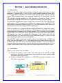
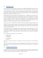
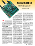
The NUE-PSK Digital Modem is a standalone, battery-operated digital modem using
Microchip dsPIC technology. Weighing about 12 ounces and requiring only 60ma at 12V
DC, the modem is easily taken to the field. For easy visibility in high or low ambient
light, the NUE-PSK modem’s backlit graphic LCD displays transmit and receive text
data, as well as band spectrum and tuning indicator. When coupled with a standard PS2
or USB keyboard and an SSB-capable transceiver, you can have an effective portable
digital mode station for PSK31, RTTY and CW modes, with a special Keyer mode for
“headless operating”! Optional internal USB card provides for saving QSO text files,
easy software updates, and real time clock.
NUE-PSK Digital Modem Operating Manual, ver 5
1
Copyright 2008-2012, Midnight Design Solutions, LLC
SECTION 1: Basic Modem Operation
1) Introduction ..................................................................................................... 4
2) Connections .................................................................................................... 4
3) Specifications .................................................................................................. 5
4) Power .............................................................................................................. 6
5) Signal Connections ......................................................................................... 6
6) Keyboard ......................................................................................................... 6
7) Operation ........................................................................................................ 7
8) RTTY Operating Details .................................................................................. 8
9) Using the “Download Config” and “Upload Config” Features ........................ 10
10) Real Time Clock Calendar (RTCC) ............................................................... 14
12) Macros .......................................................................................................... 14
13) Configuration Menu ....................................................................................... 16
14) Updating Modem Software ............................................................................ 18
15) Capabilities and usage of the optional internal USB Card ............................. 20
16) Tips & Techniques, and “Things to Watch Out For” ...................................... 23
17) Technical Support ......................................................................................... 25
SECTION 2: CW Mode Operation
SECTION 3: CW Mode QuickStart Guide
SECTION 4: RTCC Operation
SECTION 5: Keyer Mode Operation
SECTION 6: Keyer Mode QuickStart Guide
NUE-PSK Digital Modem Operating Manual, ver 5
2
Copyright 2008-2012, Midnight Design Solutions, LLC
Section 7: APPENDICES
Appendix A:
The Radio Cable
Appendix B:
Modem Schematic
Appendix C:
Optional USB+RTCC Card Schematic (rev B2a)
Appendix D:
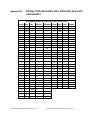
Recognized Prosigns
Appendix E:
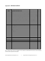
Morse Encoding with Prosigns and ASCII Equivalents
Appendix F:
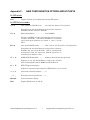
New Configuration Options and Hot Keys
Appendix G:
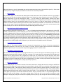
EEPROM Contents
Appendix H:
Config.txt
Appendix I:
Hot Key Map
VERSION HISTORY
The version number of this manual corresponds to the software version running in the modem,
which is displayed in the display’s “splash screen” when the modem is initially turned on. (The
small letter after the version number in the splash screen differentiates minor fixes for the
specific version.)
ver 1.15 – Initial production release.
ver 1.20 – Improved speed tuning, F10 for Tx mode, Ctrl-S char, backspace and CWID fixes,
and improved displaying/saving/loading of configurable modem settings.
ver 1.30 – Initial support for the optional USB add-on hardware and improved text entry
keyboard sequences and commands.
ver 1.33 – Full USB support adds PC Bootload and Flash Bootload capabilities.
ver 1.34 – Beacon Operating Mode added.
ver 2.10 – RTTY Operating Mode added.
ver 2.33 – Added: Upload / Download Config, spectral display improvements, Beacon Counter.
ver 3.00 – Added: Real Time Clock Calendar feature (RTCC).
Ver 4.00 – Added: CW Operating Modes (Normal, Direct, Practice) and Morse Reader
Ver 5.00 – Added Keyer Modes (for headless operating: user interface with Keyer input, Morse
output)
NUE-PSK Digital Modem Operating Manual, ver 5
3
Copyright 2008-2012, Midnight Design Solutions, LLC
SECTION 1: BASIC MODEM OPERATION
1) Introduction
PSK31 is one of the latest communications modes to capture the interest of hams
worldwide. Its inherent ability to dig out weak, nearly-inaudible signals is ideally suited
for low power QRP enthusiasts. The PSK31 digital modem engine, however, requires
intense DSP processing that is only commonly available in PC sound card. Thus the
PSK operator desiring portability for field operation is locked into using a laptop
computer as a controller, which results in a cumbersome station. But there’s hope!
The NUE-PSK Digital Modem offers a unique way for hams to get on the air using the
digital modes. No PC is required, thus enabling one to communicate using PSK31. This
self-contained, hand-held modem connects to your SSB transceiver and allows you
send and receive text data using the PSK31 digital mode.
PSK31 is actually one of many modulation techniques within the “phase shift keying”
family of communication. PSK31 operates at 31.25 bits/second, while other speeds may
be achieved using variations to the software algorithm. PSK is perhaps more accurately
termed BPSK, for bi-phase shift keying, whereby two distinct phase states separated by
180 degrees are used to convey the information. Four states may also be
encoded/decoded, as is done with QPSK (quad-phase shift keying), in order to provide
higher speeds with greater error correction ability.
The NUE-PSK digital modem can currently support the digital modes of BPSK and
QPSK, and now also support RTTY. The modem may soon support other modes such
as MSFK and even CW. In fact, the field updating capability – that is, the ability to
download new/improved programs from the Internet and simply program them into the
modem –allows users to stay current with new features and modes for years to come!
2) Connections
Ideally, you just need to use two cables:
a) Connect the modem’s “radio” cable to the “data” jack on the back of your SSB
transceiver. Most radio manufacturers today provide this way for getting audio
modulated tones to/from the rig.
b) Connect a standard PS2 keyboard, or a PS2/USB combination keyboard, to the
“Kbd” jack on the modem.
NUE-PSK Digital Modem Operating Manual, ver 5
4
Copyright 2008-2012, Midnight Design Solutions, LLC
You are now ready to rock ‘n roll using the digital modes … read on and enjoy!
3) Specifications
>
Standalone, half-duplex modulator/demodulator for amateur radio digital mode
communications
>
Handheld unit ... no PC required
>
Menus select operating modes, Squelch Thresh, PGA Gain, CW ID, Beacon, more
>
128 x 64 pixel graphic LCD displays audio signal spectrum 500 Hz to 2.5 kHz (with
backlight)
>
Tx and Rx buffers and menu system displayed in lower half of LCD using four 20character lines of text
>
“Tune” dial controls modem position along audio spectrum
>
Modes currently supported: BPSK31, QPSK, QPSK reversed, and RTTY
>
External keyboard jack: 6-pin mini-DIN, PS2-compatible
>
Standard PS2-style or dual-mode USB/PS2 keyboard (user-supplied) provides text
input for Tx entry, command/mode selection and modem frequency adjustment
>
Connection to SSB transceiver: 8-pin mini-DIN (audio in, audio out, PTT, power)
>
Powered by two internal 9V batteries (not included) or an externally-applied supply
via 2.1mm coaxial jack
>
Power requirements: 9-18V DC. Current at 12V is 60 ma without backlight, 80 mA
with backlight. The current decreases as input supply voltage is increased.
>
Field reprogrammability of internal microcontroller allows software updating in the
field by the owner
>
Aluminum enclosure provides for rugged portable use while shielding transceiver
from digital EMI
>
Enclosure dimensions: 7" x 4" x 1"
>
Single 3.75" x 5.25” pc board contains all components and connectors
>
Lightweight: < 1 lb with batteries.
>
“Tx Audio” control for precise audio level control to transceiver
>
Cable assembly provided (plug and shielded cable) for connection to the SSB
transceiver
>
Optional USB plug-in card provides ability to Record QSO text and save to USB
flash memory device. The USB port also can be used for easy software upgrades.
The USB option includes an independently powered Real Time Clock Calendar.
>
Beacon Mode provides auto-repeating message buffer for far-signal measurement
experiments.
NUE-PSK Digital Modem Operating Manual, ver 5
5
Copyright 2008-2012, Midnight Design Solutions, LLC
4) Power
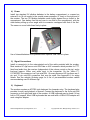
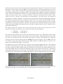
Install two standard 9V alkaline batteries in the battery compartment, or connect an
external 9-to-18 volt supply to the coaxial power connector (2.1mm) on the right end of
the modem. The two 9V alkaline batteries nestle tightly against the pc board in the
compartment. One battery lies flat and over to one side in the compartment, with the
other battery sitting up at an angle with its connector overlapped with that of the first.
The screw-on cover holds them firmly in place.
Use of internal batteries is not possible when optional USB card is in place.
5) Signal Connections
Install a connector(s) to the unterminated end of the cable provided with the modem.
Most modern HF rigs have a mini-DIN Data or AUX connector which provides for PTT,
fixed level audio from the receiver (independent of the volume control on the rig), and a
line-level (approx 100mv rms) audio input to the transmitter. On the Yaesu FT817/857/897 this connector is a 6-pin mini-DIN. On many Kenwood HF rigs there are 6pin and 13 pin mini-DIN connectors that may be used. See Appendix A for wiring
details. See the website Ordering page for a list of pre-assembled modem cables
accommodating over 50 different rigs.
6) Keyboard
The modem requires an AT/PS2 style keyboard for character entry. The keyboard also
provides for entry and playback of macros. Connect the keyboard to the 6-pin mini-DIN
connector on the right-hand side of the modem. A USB keyboard may be used if it has
built-in PS2 support. Most USB keyboards that are sold with a USB-to-PS2 adapter will
work using this adapter.
NUE-PSK Digital Modem Operating Manual, ver 5
6
Copyright 2008-2012, Midnight Design Solutions, LLC
7) Operation
Once you have the cable between the modem and the rig connected, keyboard
attached, and power available, you are ready to operate. But first, some additional setup
may also be desired, as described next.
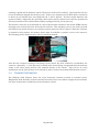
Turn on the modem. If the cabling between the rig and modem is wired correctly, you
should see evidence of signals and/or noise on the top half of the display (the spectrum
area). Tune your rig to one of the PSK sub-bands. These are typically 70-to-74 kHz
above the lower band edge on 40 and 20 meters. If there is digital activity on the band,
you should see peaks on the graphic display. The horizontal location of the peaks
corresponds to the audio frequency of each signal relative to the tuned frequency of the
rig. For example, if the rig is tuned to 14070 kHz, the display shows audio frequencies
from 500 Hz to 2500 Hz, or actual RF frequencies from 14070.5-to-14072.5 kHz.
Now for the fun ... tuning! Turn the “Tune” dial clockwise, or counterclockwise, to move
the cursor to a higher or lower frequency. The cursor is the small triangular icon just
below the spectrum display. The audio frequency is displayed when turning the dial.
Try to align the cursor with one of the peaks on the display. Don’t worry if it is not
exactly aligned. Once close to the peak, stop turning the encoder. The modem now
attempts to “lock” onto the signal and fine-tune the frequency if needed. If the modem is
able to lock onto a PSK signal, it will very shortly begin decoding the signal, and then
display characters on the screen. The time it takes for decoded characters to appear
depends on the ability of the modem to estimate the center frequency of the incoming
signal and the signal to noise ratio. Tuning can also be done by using the arrow keys on
the keyboard. The right and left arrow keys provide finer tuning, while the up and down
arrow keys provide faster tuning. The tuning rate of the encoder on the modem can also
be selected from a menu setting. Note: When tuning in receive mode, the spectral
display is frozen - this is intentional.
Now on to setup for transmission. If you have a dummy load for your rig, connect it
now.
Since PSK signals generated by the modem contain simultaneous multiple frequencies
(over a very narrow bandwidth), it is imperative that the audio output from the modem
not overdrive the input to the rig; otherwise very poor signal quality will result. To
facilitate setting the audio drive to the rig, a potentiometer on the modem may be used
to adjust the level. In addition, the modem includes provision for “measuring” the
position of the potentiometer so that it can be easily reset to the same setting in the
future. More on this later.
We have found that the best way to set up for PSK operation is to initially set up the
transceiver for normal SSB operation, including whatever power setting you usually
employ. For example, if you have a 100 watt PEP rig, set it up for 100 watts on SSB.
Switch to Digital mode if your rig provides that option; otherwise retain the SSB mode.
Then press F8 on the keyboard. This places the modem in the TUNE state, which is
denoted by “TUNE” at the top left of the display. The modem is now generating a
continuous single tone, which is fed to the audio input of the rig. The PTT signal from
NUE-PSK Digital Modem Operating Manual, ver 5
7
Copyright 2008-2012, Midnight Design Solutions, LLC
the modem should also cause the transceiver to switch to Transmit. At this point, the
“Tx Audio” control on the modem just to the right of the display can be adjusted to set
the power level of the transceiver. A transmit power of 15%-to-40% of the rig’s rated
power is recommended. (That is, 15-to-40 Watts with a 100 Watt rig). Keeping the
power at this level does two things. First, it minimizes distortion due to clipping.
Second, it avoids excessive heating in the rig finals since PSK is a 100% duty cycle
mode. A power meter is very handy for making this setting. Once the Tx Audio control
has been set, press F8 again to return to RECEIVE mode.
You should now be ready for transmitting PSK.
Pressing F10 will place the modem in TRANSMIT mode, but with a PSK idle tone being
generated, unlike the single tone used in TUNE. If you are ready to give it a try, Press
F10. At this point anything that you type on the keyboard will be converted into Varicode
characters and transmitted using PSK modulation. Pressing F10 again, will toggle back
to RECEIVE. When in TRANSMIT mode, “TX” will appear at the top left of the display.
8) RTTY Operating Details
Starting with software version 2.10, the NUE-PSK Digital Modem is now able support
full RTTY transmit and receive. Use of the modem for this older-yet-still-popular digital
mode is very similar to the other modes we support (PSK, QPSK), and is great for long
ragchews, sending “brag files” describing equipment, and contesting. Decoding
sensitivity is a bit less than with PSK31 (a mode that has been optimized for low power
operation), but tuning in someone calling CQ is a bit easier and some people say there
are more RTTY-capable hams around for potential contact, continuing the age-old
enjoyment of the hobby.
We are initially supporting 45 baud operation with 170 Hz shift between mark and space
frequencies, which classically tends to characterize the majority of RTTY use over the
years – especially with the older and original TTY equipment. We also simplify the
upper/lower sideband confusion that can exist these days by allowing the user to flip the
order of the mark and space frequencies, thus accommodating a variety of users over
all the bands.
RTTY Specs:
45 Baud, 170 Hz shift. (Other speeds and shifts may be supported later.)
Normal operating convention is to use USB for RTTY. In the event that the
station that you are attempting to connect with is instead using LSB, you may
“reverse” the Mark and Space frequencies to allow this “cross-mode” connection.
Normal mode, with the lower Mark frequency, is indicated by an N in the upper
right corner of the LCD.
Reverse mode, with the higher Mark frequency, is indicated by an R in the upper
right corner of the LCD.
NUE-PSK Digital Modem Operating Manual, ver 5
8
Copyright 2008-2012, Midnight Design Solutions, LLC
Normal and Reverse may be toggled by typing Ctrl-R while the modem is in
Receive mode. Typical usage of this toggling is to help the modem decode when
the transmitter is on a different sideband.
Generally, Normal mode is used when both transmitting and receiving stations
are on the same sideband. (USB-USB or LSB-LSB.) When the stations are on
different sidebands (USB-LSB or LSB-USB), type Ctrl-R to toggle to Reverse
mode in order to enable proper transmit and receive.
An L or F is also displayed in the upper right portion of the LCD, corresponding to
LTRS or FIGS being received by the modem. The L and F may be toggled by
typing Ctrl-C, which is useful if the corresponding LTRS or FIGS character is
missing from the incoming data stream. Thus the user can correct such an error
condition.
Setting the Modem for RTTY Operation:
Select the Mode item in the Config menu. (Press the Select pushbutton for about
2 seconds, release and rotate the Tune encoder one position clockwise.)
Rotate the Tune dial until the RTTY menu item is shown. Press the Select
pushbutton to change to that mode. The press the pushbutton again to exit back
to normal modem operation.
Notice that the spectral display now shows two cursors. These cursors are used
when tuning to a RTTY signal that has two characteristic spectral peaks
separated by 170 Hz. When the frequency is properly adjusted, each cursor will
point to a spectral peak.
Two techniques may be used for adjusting the frequency to place the cursors
beneath the two spectral peaks of the desired incoming signal. The modem’s
Tune dial may be used in the conventional manner to slide over to the received
signal. Otherwise, the receiver’s frequency dial may be adjust to move the
spectral peaks of the desired signal such that they are positioned over the two
cursors.
If the modem does not immediately start properly decoding the incoming data
stream, try pressing Ctrl-R to reverse the mark-space frequencies as described
above. The sending operator might be on an opposite sideband from what you
are using, and the mark-space frequencies would need to be the same for proper
decoding.
RTTY Operating Tips:
When using RTTY with your transceiver set to USB, the actual RF frequency is
simply the addition of the transceiver setting plus the display frequency on the
NUE-PSK modem. Further, most Digital modes (with the exception of RTTY) are
usually run in USB.
NUE-PSK Digital Modem Operating Manual, ver 5
9
Copyright 2008-2012, Midnight Design Solutions, LLC
It should be noted that RTTY will not decode weak signals as well as PSK31.
This is because the filters for RTTY are not as narrow. The modem will decode a
PSK signal that is about one S-unit lower than what can be decoded with RTTY
Macros work just fine in RTTY mode – same as in other modes, and is quite
convenient for the “brag files” that are commonly used in RTTY.
Beacon Mode works well with RTTY as well.
If you wish to use RTTY mode exclusively for a while, it may be convenient to
select Save Config from the Configure menu, thus saving your current mode
(RTTY) so it comes up by default when you next turn on the modem.
Some typed characters do not appear on the LCD. The older, 5-bit “Baudot code”
used in RTTY communications is limited in the number of characters that are
supported. Thus, only capital letters are able to be transmitted, and the only
supported “FIGS” include: -, ?, :, &, !, &, #, ‘, (, ), /, “, comma, semicolon and
period. (Characters not transmitted or displayed on the modem LCD include: %,
@, ^, *, {, }, [, ], |, \, +, =, ~, `, _, -, <, and >.) So be careful not to use these
characters when doing RTTY communications … otherwise your messages may
be received in an unusual manner. (For example: “My email is george
verizon.net”, “It costs 23.44”, “The Dow is up 2.1”, “John I went home”, etc.)
We have implemented the US version of Baudot character representation. For
example, someone on a mechanical TTY keyboard (such as the Teletype Model
19) who types a FIGS key followed by the H key, a pound sign (#) will be sent
and displayed on the NUE-PSK display. Correspondingly from the NUE-PSK
modem keyboard, pressing the # key will transmit the FIGS code followed by the
H code (or just the H code if the FIGS code was previously sent) and the #
character will be printed on the receive side.
9) Using the “Download Config” and “Upload Config” Features
This new feature pair, accessed from the modem’s CONFIG menu (beneath the Select
pushbutton), allows the operator to send (Upload) the modem’s current “configuration
settings” (user settings and macro strings) to a text file on the USB Flash Drive; edit this
text file on a PC; and then load (Download) that modified text file into the modem. This
is a great way to create macro strings offline and save them for later reminder or
modification. This is a very convenient way to ...
Send the modem's current configuration parameter settings and the current
macro strings (found under the Function keys F1-thru-F7) as a text file to the
USB thumb drive;
Edit all of the above on the PC by plugging the USB thumb drive into the PC; and
Load the modified text settings back to the modem by plugging the USB flash
drive into the modem and "Downloading" the config.txt file.
NUE-PSK Digital Modem Operating Manual, ver 5
10
Copyright 2008-2012, Midnight Design Solutions, LLC
The best way to use the new Download/Upload capabilities ...
1)
Download the blank template to your PC from http://www.nuepsk.com/software/CONFIG.TXT (right-click the link and save file to a known
location on your computer. The file is also shown at the end of this section.)
2) Open the config.txt file on your PC using the WordPad text editor. WordPad can
be found in the Start->Programs->Accessories location on your computer. (The
Microsoft NotePad text editor produces unexpected formatting problems for us.)
3) Edit the config.txt template to reflect your preferences for the modem. You can
change the text lines in the template to reflect your favorite mode, your callsign,
and other settings that you would like the modem to have when you turn power
on each time. Additionally, and most powerfully, you can edit and manage the
text strings used as the F1-through-F7 macros on the modem. For example,
changing one word in Macro 5 (F5) is much easier to do by editing here on the
PC than by re-entering the entire string anew with the modem's keyboard.
Editing Config.txt
It is very important to keep several in mind when editing the config.txt file ... The
Instructions written out at the top of the file, briefly describing how to successfully
edit the various lines. Read these instructions carefully. In short ...
1) You can ONLY edit the text on each of the 15 lines after the colon and the
space;
2) The ONLY allowable text after the colon+space on lines 1-thru-8 are shown in
the parentheses for that line. You must enter the desired option exactly as
shown, or the selected edit will not be put in place when the file is later
Downloaded to the modem.
3) You MUST be sure to retain the line termination character "|" at the end of
each macro string (lines 9-thru-15). This is the "pipe" character typically
located on the right side of one's keyboard as a shift character for the
backslash key. Failure to retain the this special character at the end of the
macro string will case a run-on (merge) of the two adjacent macro strings
when loaded back into the modem;
After edits have been made, save the file to your computer using the same
filename (i.e., you must keep the same filename config.txt), and copy that
config.txt to your USB thumb drive.
4) Load the config.txt file into your modem -- Plug your thumb drive into your
modem's USB port and in the CONFIG menu, dial up the Download Config
menu item and select Start Download. See the modem port LED blink for
perhaps about 3 seconds. The modem will then automatically reset and repower up with the new (edited) configuration parameters and/or macro strings
in place. They are automatically "saved to EEPROM" such that each time the
modem is started up in the future, the new settings will be in effect.
NUE-PSK Digital Modem Operating Manual, ver 5
11
Copyright 2008-2012, Midnight Design Solutions, LLC
Upload Config
The Upload Config feature is a lesser-needed capability that copies the modems
config settings and macro text strings to the USB thumb drive. One could use this
as a starting point for making text edits as described above, instead of using the
blank template to start with. However an updated "C02" firmware file needs to be
loaded into the USB chip, and a hardware modification is needed on the modem pcb
for this feature to work for modems purchased prior to Feb 1, 2010. See the web
page Using the USB Card (http://www.nue-psk.com/usb/using.html) and follow the
steps described in the section Installing the USB Card for the hardware mod, and
the section Programming the USB Card for installing the C02 firmware on the USB
chip.
Note that the Upload Config command is completely optional and the modem will
work just fine even if you don't make the hardware modification. Of course you won't
have the ability to send the modem's config and macro strings to the thumb drive,
but most people (including modem designers Milt and George) only use the
Download Config feature to get the edited config.txt file from the PC into the
modem. This is the most common and most useful aspect of the feature-pair.
All new modems going out the door here with USB cards, and those that have the
Full Factory Upgrade made, will indeed have the extra signal wire and the updated
"C02" USB chip firmware. This will enable those new modem users to use the
Upload Config feature as well as future features coming downstream.
However, if you chose to make the optional hardware modification, you will be able
to use the Upload Config feature, and at least one other feature coming soon -support for a USB printer. So perhaps making the simple modification when
convenient, or perhaps sending it back to us to do the low-cost mod, would be a
good thing to plan on doing. Once the hardware modification is done to support
Upload Config, you will be able to send the config and macro text to the USB thumb
drive ...
1) Place the thumb drive in the modem's USB port.
2) Selecting Upload Config from the CONFIG menu. (Press-and-hold the Select
pushbutton for a couple seconds, release and turn dial to Config Upload, and
tap the Select pushbutton to initiate the feature.)
3) See the USB port LED blink rapidly for about 15 seconds while the modem's
parameters and macro strings are written to the config.txt text file on the
USB thumb drive.
4) When the blinking has stopped and control is returned to the modem's LCD
screen, remove the USB thumb drive and place into the USB port of your PC.
You can save this file away for safe keeping or use it (instead of the
Template) as a starting point for making some edits.
See Appendix
NUE-PSK Digital Modem Operating Manual, ver 5
12
Copyright 2008-2012, Midnight Design Solutions, LLC
Default Template for Config.txt File
--------------------------------------------------------------------NUE-PSK CONFIG
--------------------------------------------------------------------Configuration file for the NUE-PSK Digital Modem for device settings and macro strings.
DESCRIPTION ... This file is generated by the 'Upload Config' selection in the
modem's CONFIGURE menu, and is written to a USB flash drive inserted into the modem.
CONFIG.TXT ... This file reflects all the current settings of the modem, and may be
modified as desired on a PC by using a simple text editor like Microsoft WordPad.
EDITING ... Editing this text file must be done very carefully by changing characters after
the colon and space. The options available for each field are listed in parentheses
for each field and must be entered exactly as shown. Special control characters are
entered into macro strings as <TXON>, <TXOFF>, <MYCALL> and <THEIRCALL>. For example ...
<TXON>Thanks <THEIRCALL>. QTH HERE IS BALTIMORE, de <MYCALL><TXOFF>
Be sure to leave the special termination character '|' in as the last string character.
LOADING INTO MODEM ... The settings and strings contained in the CONFIG.TXT file may loaded
into the modem by placing the file onto the flash drive, inserting it into the modem,
and then selecting 'Download Config' in the modem's CONFIGURE menu.
RESULTS ... If the modem is able to successfully read and transfer all settings to the modem,
'Exit' will be displayed and pressing the Select pushbutton will bring you back to the
normal operating mode of the mode with the new settings in effect. Otherwise, the modem
will beep will beep and the Download Config operation will terminate.
--------------------------------------------------------------------1) My Call: N2APB
2) Log Fname: NUE-PSK.txt
3) PGA (x1,x5,x16,x32): x16
4) Mode (BPSK,QPSK,QPSK/R,RTTY): BPSK
5) BackLight (ON,OFF): ON
6) SQLCH (25, 50): 25
7) AFC (ON,OFF): ON
8) CWID (ON,OFF): OFF
9) Macro 1: <TXON>CQ CQ CQ CQ CQ de <MYCALL> <MYCALL> <MYCALL> PSE K <TXOFF> |
10) Macro 2: My Macro 2 |
11) Macro 3: My Macro 3 |
12) Macro 4: My Macro 4 |
13) Macro 5: My Macro 5 |
14) Macro 6: My Macro 6 |
15) Macro 7: My Beacon Macro |
NUE-PSK Digital Modem Operating Manual, ver 5
13
Copyright 2008-2012, Midnight Design Solutions, LLC
10) Real Time Clock Calendar (RTCC)
In receive and transmit modes, the date and time are displayed on the top line of the
128 x 64 graphical display. In other modes, the entire screen is used so the date and
time are not displayed; however, the date and time are maintained so they will be
current when next displayed. When first powered up, the time is initialized as “00:00:00”
and the date is not displayed until the date is input to the modem either by the operator
(see Configuration Menu) or by the optional USB option card (automatic, if installed). If
the time is not updated, it can serve as a running time meter showing how long the
modem has been turned on. The operator may also choose to turn the date and time
displays off.
The date display is located in the upper left corner as an eight-character string
formatted as: “MM/DD/YYYY. The time display is located in the upper right corner as
an eight-character string formatted as: “hh:mm:ss” in a 24-hour format. To conserve
display space, both are displayed using a special 3 x 5 font with no space between
characters instead of the standard screen font which is a 5 x 7 font with one column of
pixels between characters (6 x 7 pixels used per character).
The time is updated every second either by the Real Time Clock Calendar (RTCC)
circuits on the USB option card or, when the USB option card is not installed, by a onesecond timer in the modem. The main differences between these two approaches are
accuracy and persistence. The RTCC on the USB option card uses the same type of
crystal used in quartz watches to generate a very accurate time base. The modem time
base is derived from the main system clock and is less accurate. The RTCC is powered
by its own separate battery so it will maintain accurate time even when the modem
power is turned off. Each time the modem is turned on, it verifies that the RTCC is
present and automatically sets its copy of the date and time from the current RTCC
settings. When the RTCC is not detected, the user must manually enter the date and
time each time the modem is powered up.
When the USB option card is first installed, the date and time settings will not be
accurate. The operator must enter them once. From then on, the RTCC will maintain
them whether or not the modem is powered on. The RTCC knows nothing about time
zones and daylight savings time. The operator can choose to use either local time or
Universal Time and must change the time ahead or back one hour to account for
daylight savings time, if desired. The RTCC programming is aware of leap years so it is
not necessary for the operator to make leap year adjustments in the date. Of course,
the operator will have to reenter the date and time after replacing the RTCC battery.
(Note: Whenever a battery is installed onto the USB card, pin 4 of PIC controller U3
should be grounded quickly once with a touch of a clip lead in order to properly reset the
PIC and start the clock programming.)
12) Macros
a) General Macro Usage
NUE-PSK Digital Modem Operating Manual, ver 5
14
Copyright 2008-2012, Midnight Design Solutions, LLC
Macros are pre-recorded strings of characters for subsequent convenient
playback. If you wish to use macros, now is a good time to do it.
For those already familiar with PSK operations, macro setup is similar to many of
the popular PSK programs.
Macro recording is initiated by pressing the Ctrl key plus the function key that you
want to be associated with your macro. Let’s go through an example of entering
your callsign into EEPROM memory and setting up a CQ calling sequence, as
shown below. I’ll use my callsign in this example, but of course you should use
your own.
a) Record your callsign into EEPROM …
Ctrl-M
n2apb
Ctrl-Z
b) Record the CQ calling sequence into the F1 macro ….
Ctrl-F1 Ctrl-S cq cq cq de Alt-M k Ctrl-Q Ctrl-Z
Now play the macro by pressing F1 and see …
Tx comes on, “cq cq cq de n2apb k”, Tx turns off
You can also record the other station’s call sign “TheirCall” in RAM (not in
nonvolatile EEPROM) by pressing Ctrl+T, TheirCall and Ctrl-Z to end the entry.
To insert the other station’s call sign into a macro, simply use Alt+T in the macro.
Then, when you play the macro the other station’s call sign will be inserted into
the macro. In this way whenever you enter a new call sign using Ctrl+T, you do
not need to re-record the macro to use the new call sign.
b) Special macro usage: Beacon Mode
Using this feature, the user is able to specify a text string up to 256 characters in
length into macro buffer F7 and then turn on Beacon Mode by pressing Shift-F9.
The F7 macro should contain the Tx-ON control character Ctrl-S at the start of
the string and the Tx-OFF control character Ctrl-Q at the end. The beacon
transmission will then start and stop automatically with nothing being transmitted
during the pauses.
Once in Beacon mode, the reverse-video characters "BCN" are displayed at the
right edge of the display and the F7 buffer begins transmitting as the text is
displayed on the LCD.
Since the Tx-OFF control character Ctrl-Q is the last character in the string, the
modem drops out of Tx mode and the modem stays in Rx mode until the Beacon
Interval timer expires.
When the Beacon Interval time expires (which must be greater than the time
required to transmit the F7 buffer), the F7 buffer transmit cycle begins again.
This "beacon cycle" continues as long as the modem is powered (i.e., transmit
F7 buffer, wait for Beacon Interval to timeout, transmit F7 buffer, ...)
Beacon mode may be turned off at any time by pressing Alt-F9.
NUE-PSK Digital Modem Operating Manual, ver 5
15
Copyright 2008-2012, Midnight Design Solutions, LLC
The Beacon Interval is able to be set within the modem's Configure menus ...
press-hold the Select pushbutton, dial two positions counter-clockwise and select
Beacon Interval. Adjust the dial to select time in seconds for the start of every F7
buffer transmit cycle. It is important that the time be greater than the time
required for F7 buffer to transmit. A good guideline is to first program the F7
buffer with the desired string and play the F7 buffer once by pressing F7 while in
Tx mode. Time the transmission and add the number of seconds desired before
the next transmission. That combined time will be the Beacon Interval.
The user-set Beacon Interval time in the Config menus is retained only as long
as modem power is applied. You will need to re-enter the time each time you
power up the modem. The default Beacon Interval is 60 seconds.
Usage Example: A beacon is desired for sending "v v v v N2APB 10mW PSK
Beacon"
a) Enter string to F7:
"Ctrl-F7, Ctrl-S v v v v N2APB 10mw PSK Beacon Ctrl-Q, Ctrl-Z"
b) Send F7 buffer to determine length: F7 (Takes about 6 seconds)
c) Set Beacon Interval to 15 seconds:
- press-hold Select, dial to Beacon Interval and select it;
- dial to 15 seconds;
- tap Select twice to exit back to normal modem display.
d) Turn on Beacon Mode: press Shft-F9
... see modem transmit F7 buffer on 15 second intervals
e) Turn off Beacon Mode: press Alt-F9
13) Configuration Menu
Configuration of the modem is accomplished by using a menu system. For example,
you can select among the available modes PSK, RTTY, QPSK, and QPSK reversed.
You can also change the software squelch setting, the gain of the programmable gain
amplifier (PGA), turn CW Identification on or off, turn the display backlight on or off,
change the tuning “increment”, monitor battery voltage, or monitor the setting of the TX
audio potentiometer. Other items may be added to the menu at a later time.
The method of menu access is through the “Select” button on the menu and the Tune
dial. Pressing and holding the Select button for more than ½ second will activate the
menu system. When initially activated, the display will show “Configure” on one line,
followed by “Exit” on the line below. If you wish to abort configuration, simply tap the
Select button at this time. If, on the other hand, you wish to configure one of the modem
settings, simply rotate the dial clockwise or counter clockwise to cycle through the top
level menu selection. Once you see an item that you wish to change, tap the Select
button again. This will then allow you to cycle through a list of choices, again by rotating
the Tune dial. When the choice you wish to make appears on the display, tap the Select
button again. This will record your choice, and the menu will revert to the top level,
showing “Exit” as the default choice. You can now make additional changes or tap the
Select button again to exit the Configuration menu.
NUE-PSK Digital Modem Operating Manual, ver 5
16
Copyright 2008-2012, Midnight Design Solutions, LLC
The current menu choice is the item initially displayed when a given menu is selected.
For example, if you dial up Squelch Threshold menu item and change it to show “25”,
the next time you access this menu item it will still show as “25”, thus allowing you to
always see the current setting before (possibly) changing it.
Another way to see a full “status display” of current settings is to press the F12 key.
This function shows the current value for each of the changeable settings: Mode,
Squelch, CwID, Backlight and PGA. This is a convenient way to determine at a glance
how your modem is currently configured.
Once a change is made in Config mode, the display shows “Exit” as a prompt for you to
tap the Select button to get out of Config mode; and once you exit that change will be
effect as long as the modem has power applied. However, you have an opportunity to
save any changed Configuration settings to nonvolatile memory such that those new
settings will be in effect the next time you power up the modem. Just turn the Tune dial
one position counterclockwise and see the option for “Save Config”. Tapping Select at
this point will save the current settings to EEPROM and they will be loaded and put into
effect when you next turn on the modem.
See a useful list of available menus and hot key assignments in the APPENDIX, along
with a sample usage scenario for saving data to the USB device.
NUE-PSK Digital Modem Operating Manual, ver 5
17
Copyright 2008-2012, Midnight Design Solutions, LLC
14) Updating Modem Software
Increasingly today, microcontrolled devices have an ability to be “field updated” with
new features and software updates made available by the designers. So instead of
needing to send your modem back for re-programming to get these new capabilities and
bug fixes, you can simply download the latest-and-greatest software from the Internet
and send it to the modem and the hardware automatically updates its internal memory
with the new program. What a great way to keep your project completely up to date with
the latest features!
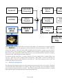
Three methods are available to perform this field updating of the software:
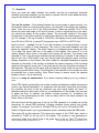
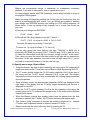
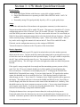
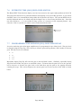
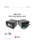
a) External Serial Adapter between Modem and PC – With this method you just
need to connect your PC serial port to the modem using a simple adapter, and
send it the new software obtained from the NUE-PSK website whenever new
capabilities are made available. We designed a TTL serial port into the modem,
accessible via a 4-pin connector P4 located inside the battery compartment. Just
connect your computer’s USB port to an inexpensive USB-to-TTL adapter such
as the CP2102 from SparkFun9, and plug the adapter into P4. When you select
the PC Bootload option in the Config menu and run the ‘prog’ loader program on
your PC, the new software will be transferred to the modem. Once you powercycle the modem, the modem will be running the latest software release
containing, for example, a new digital mode, some new I/O capabilities, and so
on. This is really quite a convenient and powerful capability for the project.
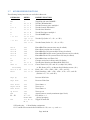
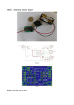
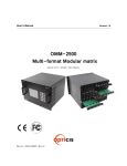
Photo 10: CP2102 USB-to-TTL interface from
SparkFun
Figure 5: Schematic of an easy RS-232 interface
to the NUE-PSK Digital Modem
b) PC Bootload using optional internal USB Card – Connect the modem to a
USB port on the PC using an A/B USB cable and upgrade the modem software
from the PC in the same manner as with the external serial adapter. Just dial up
the PC Bootload function in the Select menu, activate the same "prog" program
on your PC as before, and watch your modem software get upgraded.
NUE-PSK Digital Modem Operating Manual, ver 5
18
Copyright 2008-2012, Midnight Design Solutions, LLC
c) Flash Bootload using optional internal USB card – Use a USB flash “thumb
drive” to load new software into the modem, thus eliminating any need for cable
connection to the PC. See the USB section for details.
Loading New Software using an External Serial Adapter
In general, the process is simply to select PC Bootload item in the modem’s Config
menu, connect the serial adapter, and run a program called prog on your PC.
Important ... If you haven't yet proved out your serial adapter connection between
your PC and modem, you should first follow the steps outlined on the web page
Serial Interface Checkout (http://www.nue-psk.com/serial_interface). If you
cannot do the operation specified there, you will not be successful trying to load new
software into the modem.
First, you'll need to "get ready" by first doing a couple of things ...
1) Determine the COM port number of your USB or RS-232 serial port -- You can find
this out by clicking START and then right-clicking My Computer. Select Properties and then
the Hardware tab. Click Device Manager and find the Ports line item in the list. Expand that
line item and see that the Communications Port will have a COM number shown. That is the
serial COM port number that you'll use.
2) Get the PROG program onto your local computer -- You can download prog from
http://www.nue-psk.com/serial_interface/prog.exe. Save the file in a convenient place,
like at the root of your C drive. (When your computer prompts for the save location, enter C:\
)
3) Download the latest modem software to your computer -- Download the software file
modem2_10h.zip from the Software section on the website www.nue-psk.com, and place
it in the same location as you did the prog program above.
Next, perform the following steps to connect the PC to your modem using your serial
port ...
4) Connect the serial adapter between the modem and the PC -- You will either (a)
connect a serial adapter to a serial port cable that is plugged into your computer, and then
connect the adapter to the 4-position "Field Programming" pinheader (P4) located on the
bottom side of the modem pc board, as accessed form the battery compartment; or (b)
connect an A/B USB cable between the PC and the USB card’s square connector on the
side of your modem.
5) Open a Command Window on the PC -- You can bring up this window by clicking in
START, Run ... and enter Command. Navigate to where you saved the prog.exe program.
If this was at the root of the C drive, just enter CD \ .
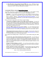
6) Enter command to run the "prog" program -- From the prompt inside the Command
Prompt window, type the following command line ... but do not yet press <Enter>. For
example, on my system that uses the COM1 serial port, I would type ....
prog -i com1 modem3_0(modem+lowboot).hex
NUE-PSK Digital Modem Operating Manual, ver 5
19
Copyright 2008-2012, Midnight Design Solutions, LLC
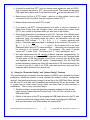
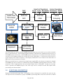
7) Start the PC Bootload process – Select the PC Bootload function in the modem’s
Config menu, and then select Start Download. Next press the "Enter" key on the PC
keyboard to execute the command you previously entered.
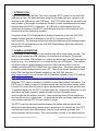
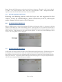
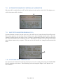
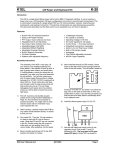
8) See the PC screen start displaying the downloading indicators -- See the PC screen
show a series of "periods" as the software gets downloaded to the modem and burned into
flash. You will see about 3 rows of the periods and then it will stop. At that point the modem
will automatically restart and you'll see the splash screen display the new version number
"2.10h".
(NOTE: This screenshot shows the command line for loading version 1.20 software. The sequence is
the same for all version numbers, but instead using the filename of the latest software version.)
15) Capabilities and usage of the optional internal USB Card
Three major features are enabled by having the USB card installed: REC mode, Flash
Bootload, and PC Bootload. These features are very powerful and will greatly
enhance your digital modem experience.
Software v1.34 (or later) must be loaded for these features to work as described ... and
you must have firmware "C01" loaded on your USB card. See the USB web page for
instructions on loading C01 firmware if you constructed the USB card from a kit.
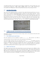
= = = = = = = = = = = = = = = = = = = = = = = = = = = = = = = = = = =
REC MODE -- Recording QSOs to a USB flash memory device
Insert a USB flash memory device into the modem connector. The LED on the side
of the modem will come on.
Type Ctrl-U on the modem keyboard to place the modem into RECORD mode. You
will see “REC” displayed on the right side of the modem display and the LED on the
USB port will start blinking rapidly, indicating that it is ready to receive any text that
NUE-PSK Digital Modem Operating Manual, ver 5
20
Copyright 2008-2012, Midnight Design Solutions, LLC
you may type in Tx mode or any text that is coming across the LCD in Rx mode.
(Note: If the USB card is not in place, or not working, the REC will be shown briefly
on the display and a beep will be sounded by the modem to indicate that an error
condition is present.)
Assuming things are working (no beep and the LED blinking rapidly), place the
modem into Tx mode (press F10) and start typing some text. You do not need to be
connected to your transceiver to try this out. You will see the text displayed on the
modem LCD of course, but it is also being simultaneously written to your USB flash
device.
Type Ctrl-U again to stop the REC mode and you will see the USB port LED stop
blinking and remain on continuously.
Remove the USB device and plug it into your computer. You will notice a new file on
the stick called NUE-PSK.TXT. If you open this file you will see the text that you
typed while in Tx mode, and any other text that might have been displayed while in
Rx mode.
As summarized on the Command Reference sheet, two other USB-related features
are available to you. One is that you may specify your own unique filename for the
data being recorded to the USB device while plugged into the modem. Before
turning on REC mode (CTRL-U), you may type CTRL-N and you will be prompted at
the top of the modem display to enter a filename. Give it any standard 8.3 format
filename that is useful to you. (8.3 is 8 characters followed by a period and 3 more
characters as an extension, like “Test1234.txt”.) Don’t forget to use CTRL-Z key to
end this entry.)
The other USB-related feature is that you may Insert your own text into the data
stream being recorded to your USB flash device. For example, after getting into REC
mode (CTRL-U) but before starting up a QSO, you might wish to enter the current
date, time or operator name in order to have a better record of the QSO
downstream. To do this, type CTRL-I and you will prompted at the top of the screen
to enter this “offline” text. Don’t forget to end your entry with a CTRL-Z in order to
return back to Tx or Rx mode. Remember, what you enter in this Insert mode is not
transmitted, but it is only text that is inserted into the stream of data going to your
USB flash memory device.
The QSO recording format
The QSO recording format for flash drives is enhanced with additional information including
date and time. At the start of each recording session (initiated by a CTRL-U) the following
text block is written to the file:
*****************************************
* START RECORDING <MM/DD/YY hh:mm:ss> *
*****************************************
This text block is always followed by a blank line. At the end of the recording session
(terminated by another CTRL-U), the following text block is written to the file:
****************************************
* STOP RECORDING <MM/DD/YY hh:mm:ss> *
****************************************
This text block is always preceded by a blank line.
NUE-PSK Digital Modem Operating Manual, ver 5
21
Copyright 2008-2012, Midnight Design Solutions, LLC
The start of each recorded receive session contains the following preamble text:
* * * RECEIVING:
<hh:mm:ss>
This text is followed by a single space character and then the received text as received, no
formatting.
The start of each recorded transmit session contains the following preamble text:
* * * TRANSMITTING:
<hh:mm:ss>
This text is followed by a single space character and then the transmitted text as
transmitted, no additional formatting.
When the operator inserts text in the recording (CTRL-I), the following text is inserted in the
file:
* * * INSERTING:
<hh:mm:ss>
This text is followed by a single space character and then the operator-keyed text, no
additional formatting. When the operator ends the insert operation with CTRL-Z, the modem
resumes recording the interrupted mode with the appropriate RECEIVING or
TRANSMITTING preamble.
= = = = = = = = = = = = = = = = = = = = = = = = = = = = = = = = = = = = =
FLASH BOOTLOAD -- Loads new modem software from a flash device
This feature allows you to upgrade your modem software from a file placed onto a
USB thumb drive. Just place the latest version of the modem software (in a special
format, named mem.dat) onto your USB drive, as downloaded from the NUE-PSK
website. This file is then automatically loaded into your modem. Thus, you no longer
need to use a serial adapter to upgrade your modem software!
1) Download the modem software mem.dat to your computer from the Latest
Software section of the modem web page, and then copy the file to your thumb
drive.
2) Insert the USB drive into the modem and select the Flash Bootload function in the
modem menu within the Select pushbutton items list. (Hold the Select pushbutton
down for more than 1/2 second and turn the dial counterclockwise until Flash
Bootload is displayed, and tap Select again to select this menu item.)
3) Turn the dial until “Start Bootload” is showing then tap the Select pushbutton. You
will note some blinking of the LED on the USB drive itself (if it has an LED), and in
about 15 seconds the modem will reboot and start up the software version just
loaded.
= = = = = = = = = = = = = = = = = = = = = = = = = = = = = = = = = = =
PC BOOTLOAD -- Loads new modem software from your PC
This feature allows you to load a new version of a software hex file onto your modem
from your PC, much in the same way as you did previously when using a serial
adapter.
NUE-PSK Digital Modem Operating Manual, ver 5
22
Copyright 2008-2012, Midnight Design Solutions, LLC
1) Download from the modem website the software you wish to load into your
modem, for example modem2_10h(modem+lowboot).hex, and then connect your
modem to the USB port on your PC. You will use a suitable cable that plugs into the
square USB jack on the modem and into the rectangular USB jack on the PC. When
you plug in both ends of the cable, the computer will recognize the USB port.
2) Ready your PC in the same fashion as done previously when using the separate
serial adapter. Bringing up a Command Prompt window on the PC, navigating to the
location where the PROG program and your modem software hex file reside (the
root
of
the
C:
drive
is
convenient)
and
type:
prog -i com5 modem2_10h(modem+lowboot).hex where the COM port number is
that used by your PC for the USB ports. Do not hit <Enter> yet until you have
readied the modem side of the connection.
3) Select the PC Bootload function in the modem menu underneath the Select
pushbutton. (Hold the Select pushbutton down for more than 1/2 second and turn
the dial counterclockwise until Flash Bootload is displayed.)
4) Press the Select pushbutton and turn the dial one notch to see "Start Bootload"
displayed.
5) Tap the Select pushbutton to select the Start Bootload item on the modem, and
then press the <Enter> key on the PC keyboard to run the PROG program. You will
see the standard series of about 100 dots appear on the PC screen to signify the
program download process. When the dots stop appearing, the modem will reset
and the new software will be running.
NOTE 1: You will need to have the FTDI USB driver installed on your PC before
attempting to use this PC Bootload feature. To install the driver, download the driver
installation zip file from:
www.nue-psk.com/software/CDM%202.04.06%20WHQL%20Certified.zip
and expand it onto a temporary file on your PC, and then plug in the cable from your
modem. With the modem power turned on, the PC will recognize that a new USB
device is plugged in and Device Found Wizard will pop to lead you through the
process of installing the new driver. At the appropriate point indicate that you wish
to specify that that PC searches for the driver at the location you have the temporary
folder. When the PC indicates that the device is successfully installed, you can use
the PC Bootload feature. NOTE: If you need help with this process, you can
download and study the FDTI application note called "AN232R-03 Driver PreInstallation Document”, located at:
http://www.nue-psk.com/usb/AN232R-03_DriverPreInstallation.pdf
16) Tips & Techniques, and “Things to Watch Out For”
Here is a useful section that will undoubtedly grow in length over time. Please be sure
to often check the NUE-PSK website for the latest online information.
NUE-PSK Digital Modem Operating Manual, ver 5
23
Copyright 2008-2012, Midnight Design Solutions, LLC
a) Signal Level – Setting the right drive level to your SSB rig is essential to success
when operating the PSK31 mode. Please be sure to read the corresponding
section on the NUE-PSK website containing lots of tips on this topic.
b) Inserting Plugs to the Modem – You will want to be sure that you fuly insert the
Radio and Keyboard plugs into the connectors on the modem. Failure to do so
could well result in unusual, intermittent or “noisy signal” symptoms during usage.
When inserting, be sure to press firmly in the direction of insertion – do not
“wiggle the plug while inserting. Same for unplugging – just pull it back firmly.
(Care in this area will save the life of the connectors on the modem.)
c) Tap-Hold to Select Config – As described elsewhere in this manual, you can
get into the Configuration menu in order to make various settings in your modem.
Config is entered by a press-and-hold of the Select pushbutton … just press the
pushbutton for about one second (say “one one thousand”) and release it to see
the options that you can further select by rotating the Tune control. You can
select any other operation or menu selection merely with a quick tap of Select.
d) Tx Audio Level Setting – This menu selection in Config will show you the
relative position of the mini-pot used for the control on the top of the modem.
The control currently ranges from 0%-to-26%, or -60%, -125% or even -160%,
etc. Don’t worry about the specific number at this time; we will make the
readings more consistent from unit-to-unit in a future software release.
e) Spectrum Artifacts – When viewing a moderately-strong signal at the midscale
point on the modem’s LCD spectrum (which corresponds to 1500 Hz), “noise” will
also be seen on the far right and far left ends of the spectrum display. This is
common and is an artifact of the DSP process of the signal, and it will occur even
when viewing received signals a bit below or above the spectrum midpoint.
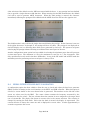
f) How We Tested the Modem (in part) – Some might find this info helpful in
testing their own modems. We had direct audio connections to a laptop running
Digipan, with the audio in/out cables connected to the soundcard headphone/mic
connectors, respectively. We then commanded the modem to transmit at 1500
Hz and viewed the classic two-tone “railroad track” signal on the Digipan waterfall
display. Ensuring that the Digipan frequency (i.e., the red diamond) was
centered on the tracks to ensure we were tuned to the modem’s signal, we
adjusted the Tx Audio level control fully counterclockwise to generate no signal,
then increased it slowly in a clockwise direction while viewing the IMD reading on
the Digipan window. We stopped turning the control when the IMD reading got to
a -54 dB level, after which turning it further has no more effect. We found this
level to be an ideal setting of the Tx Audio level delivered by the modem.
Characters typed on the modem keyboard could then be seen on the Digipan
receive window. We then turned the channel around (i.e., set Digipan to Tx and
the modem to Rx), and saw n the modem display the characters typed into
Digipan. [Note, you should follow the adjustment procedure elsewhere in this
manual when connected to a radio.]
NUE-PSK Digital Modem Operating Manual, ver 5
24
Copyright 2008-2012, Midnight Design Solutions, LLC
17) Technical Support
In case of questions or problems, feel free to send an email with your comments to us at
[email protected].
Be sure to also check the NUE-PSK website at www.nue-psk.com for the latest
information, software availability and tips & techniques to make your digital mode
operating experience enjoyable. This printed manual will be updated frequently with
corrections and new capabilities presented in the current software, so be sure to always
check out the website.
Another great source of information and camaraderie with fellow owners of the digital
modem is the NUE-PSK email reflector on Yahoo Groups. If not already signed up for
this great communication forum, go to www.yahoogroups.com and search for the
group called NUE-PSK. You can view all the messages posted there, and if you join (for
free!), you will be able to post questions and comments yourself, as well as access the
files in the group.
NUE-PSK Digital Modem Operating Manual, ver 5
25
Copyright 2008-2012, Midnight Design Solutions, LLC
Section 2: CW Mode Operation
1.
INTRODUCTION ............................................................................................................................ 3
2.
GENERAL DESCRIPTION ................................................................................................................. 4
3.
2.1
TUNING ................................................................................................................. 4
2.2
CW RECEPTION...................................................................................................... 5
2.3
CW TRANSMISSION ............................................................................................... 6
FUNCTIONAL DESCRIPTION ........................................................................................................... 6
3.1
CW TRANSMISSION ............................................................................................... 7
3.1.1 3.1.1 Status Display ............................................................................................ 7
3.1.2 Transmit Side Tone ............................................................................................. 7
3.1.3 Keyboard Input.................................................................................................... 8
3.1.4 Transmit Text Display ......................................................................................... 9
3.1.5 CW Macros .......................................................................................................... 9
3.2
CW RECEPTION.................................................................................................... 10
3.2.1 SPACE Processing ........................................................................................... 10
3.2.2 MARK Processing ............................................................................................. 11
3.2.3 Receive Text Display ........................................................................................ 12
NUE-PSK Digital Modem Operating Manual, ver 5
1
Copyright 2008-2011, Midnight Design Solutions, LLC
3.2.4 Spectrum Display .............................................................................................. 13
3.2.5 Receive Decode Parameters ............................................................................ 13
4.
5.
CONFIGURATION ............................................................................................................................ 16
4.1
EEPROM MAP ....................................................................................................... 16
4.2
CONFIG.TXT FILE ................................................................................................. 16
OTHER CHANGES ........................................................................................................................... 17
5.1
DATE FORMATS ................................................................................................... 17
5.2
ENTERING THEIR CALL AND MY CALL.............................................................. 17
5.3
SERIAL NUMBERS ............................................................................................... 19
5.4
KEYER INPUT ....................................................................................................... 20
5.5
DEFAULT RECORD (LOG) FILE NAME ............................................................... 21
5.6
BATTERY VOLTAGE DISPLAY ............................................................................ 21
NUE-PSK Digital Modem Operating Manual, ver 5
2
Copyright 2008-2011, Midnight Design Solutions, LLC
1. INTRODUCTION
This section describes the CW operating mode. This added operating mode is implemented
in firmware and is available with all hardware versions and options. Adding the CW
operating mode to an existing NUE-PSK modem will only require a firmware update. Before
getting into the details, some definitions are in order.
Throughout this specification the term “SPACE” refers to a key-up condition and the term
“MARK” refers to a key-down condition. The term “DIT” refers to the MARK duration of a
Morse code dot and the term “DAH refers to the MARK duration of a Morse code dash.
DITs and DAHs are referred to as “Morse elements”. Morse elements are combined to form
characters. Characters can be letters, numbers, punctuation marks, and prosigns. A
prosign is a combination of elements representing something other than the characters and,
in this context, something unique to amateur radio. Throughout this specification, prosigns
are represented by two, lower-case, boldface letters the Morse code characters for which
are sent, run together, with no inter-character space between them. Familiar prosigns
include bk (BreaK and sk (Silent Key). Normal, alpha Morse characters are represented as
upper-case, boldface letters.
The terms “intra-character SPACE” and “inter-element SPACE” refer to the duration of the
SPACE between DITs and DAHs within a character. The term “inter-character SPACE”
refers to the SPACE duration between characters. The term “inter-word SPACE” refers to
the SPACE duration between words.
A basic time unit (Tcw) is used to quantify time durations of Morse code elements and
SPACEs. Standard Morse code durations for Morse elements and SPACEs are as follows:
DIT ................................. 1 x Tcw (“short MARK”)
DAH ............................... 3 x Tcw (“longer MARK”)
Inter-element SPACE..... 1 x Tcw (between DITs and DAHs within a character)
Inter-character SPACE .. 3 x Tcw (between characters)
Inter-word SPACE.......... 7 x Tcw (minimum, between words)
Since all timing is derived from Tcw, its duration determines the transmission rate
commonly stated in “words per minute” or “wpm”. A standard “word” has been defined for
computing wpm. That word is “PARIS ” which, in Morse code, has ten DITs and four DAHs
and contains exactly 50 Tcw including the ending inter-word SPACE. Using this standard
word, the relationship between Tcw and wpm is: wpm = 1200 / Tcw, where Tcw is
expressed in milliseconds and all element and SPACE durations are standard as listed
above.
NUE-PSK Digital Modem Operating Manual, ver 5
3
Copyright 2008-2011, Midnight Design Solutions, LLC
2. GENERAL DESCRIPTION
While receiving CW, the modem will copy and display standard Morse code characters
received through an audio output from a transceiver. While transmitting, the modem will
transmit standard Morse code characters as entered by the operator or contained in macros
via the audio input to a transceiver. The transceiver shall be in DATA, PACKET, or SSB
mode, not CW mode. CW mode is selected for the modem using the MODE entry in the
configuration menu system. Once CW mode is activated, the modem will be in the receive
state until transmission is activated. The transmit state may be activated or deactivated in a
number of ways as described below.
2.1 TUNING
Normally, the transceiver translates received RF to baseband audio referenced to the
frequency displayed on the transceiver dial. The modem uses DSP techniques to analyze
and demodulate the audio signal and extract the desired information according to the mode
the modem is operating in. The modem can process signals in a 2 KHz spectrum of audio
frequencies ranging from 500 Hz to 2500 Hz; however, in CW mode, the tuning range is
limited to 1500 Hz at the top end. Tuning is aided with a spectrum display representing the
energy detected in each of 128 frequency slices or “buckets”. Each bucket represents a
15.625 Hz slice of the spectrum and is displayed as a vertical bar chart or histogram. The
length of each of the 128 bars represents the amount of energy detected in the associated
bucket. The histogram data is generated by a 512 term, Fast Fourier Transform with a
sampling rate of 8,000 samples per second.
The spectrum display includes a cursor representing the current frequency of interest. The
cursor may be moved in a couple of ways by the operator. During normal operation, the
operator sets the transceiver frequency dial to a base frequency and can then tune the
modem to cover a range of between 500 Hz and 1500 Hz above the base frequency.
Tuning can also be done by leaving the modem cursor at a fixed position (e.g., at 800 Hz)
and tuning the transceiver to move displayed bars to the cursor. Generally it is more
convenient to do gross tuning (1 KHz increments) with the transceiver and fine tuning with
the modem
The normal modem tuning features are available in CW mode; however, the tuning range is
limited to a maximum of 1500 Hz and confined to the left half of the display. During
operation, the transceiver is tuned to get the desired signal’s bucket on the display. This is
done by listening to the transceiver audio and watching the modem display as the
transceiver is tuned. Fine tuning is then done by moving the cursor to the bucket. The
modem tuning controls allow tuning in steps of 10, 5, 2, or 1 bucket from the keyboard. The
modem also provides a tuning dial that can be rotated left or right to move the cursor down
NUE-PSK Digital Modem Operating Manual, ver 5
4
Copyright 2008-2011, Midnight Design Solutions, LLC
or up the spectrum display. In receive mode, pressing the End key on the keyboard will
activate the Acquire function and the cursor will automatically be moved to the bucket with
the most energy within two buckets of the current bucket. The Acquire function is
automatically activated after a short timeout following any tuning of the modem.
It will not be apparent to the operator but the dial frequencies on the two transceivers will be
off by the modem tuning frequency when the remote transceiver is operating in CW mode.
For example, if the local transceiver is tuned to 14,060.00 KHz and the modem is tuned to
800 Hz, the remote transceiver will be tuned to 14,060.80 when its tuning indicator indicates
“on frequency”.
Note that the FFT generation is much too slow to be used for demodulating the CW signal.
It is only intended as an aid to tuning. Instead, a specialized DFT algorithm called a
“Goertzel filter” is used to process the raw ADC output. The Goertzel algorithm is very fast
to compute and very efficient when the application only requires analysis of a small number
of frequencies when only energy levels are needed and phase information is not needed.
The most common use for Goertzel filters is to decode the DTMF tones generated by
telephone keypads.
2.2 CW RECEPTION
In order to receive CW accurately, the signal must have certain characteristics often
attributed to an operator with, what is commonly referred to as, a “good fist”. Best results
will be obtained by the modem when the signal is generated by a computer (or a
microcontroller) and strictly follows normal Morse code standards (e.g., a DAH is three times
a DIT, inter-word SPACEs are at least 7 DITs, etc.). This case includes modem-to-modem
CW communication. The most probable causes of errors will be received signal fading
(QSB), interference from other stations operating near our operating frequency (QRM), or
excessive noise (low Signal-to-Noise ratio) in the receive channel. Some of these sources
can be handled through filtering, adjusting the gain of the input amplifier, or adjusting the
MARK-SPACE threshold level. There are limits, however, and solid CW copy by the
modem will require a fairly strong, distinct, and clear tone from the receiver audio channel
with the receiver tuned to produce a CW side tone within the 1 KHz audio spectrum
processed by the modem in CW mode.
The second-best choice would be an electronic keyer operating in fully automatic mode so
that it will strictly control the duration of DITs and DAHs and the SPACE between them. In
this mode, the transmitting operator is responsible for inter-character and inter-word SPACE
duration. The receive algorithm will try to accommodate variations in this timing but there
are limits. (Some of the parameters used to define various CW elements can be tweaked
NUE-PSK Digital Modem Operating Manual, ver 5
5
Copyright 2008-2011, Midnight Design Solutions, LLC
manually by the operator.) The following are some of the problems that will occur when
these limits are exceeded:
Inter-word SPACE too short .........words run together
Inter-character SPACE too long ...extra spaces between characters
Inter-character SPACE too short ..characters run together
The third-best choice would be an electronic keyer operating in semi-automatic (“bug”)
mode where the keyer controls the DOT duration and the SPACE between consecutive
DOTs and but the operator is responsible for DASH durations, the SPACES before and after
DASHES, and those items listed above for an electronic keyer in fully automatic mode.
Exceeding limits in these areas adds the following to our list of problems:
DASH duration too short ..............DASHs interpreted as DOTs
Inter-DASH SPACE too long ........characters split into two or more false characters
Inter-element SPACE too short ....missed DOTs (combined into long DASHs)
Inter-DASH SPACE too short .......missed DASHs (combined into very long DAHs)
These conditions can also cause the modem to recalculate an inaccurate Tcw which will
affect the accuracy of decoding following characters.
2.3 CW TRANSMISSION
During CW transmission, the operator selects a transmission speed (words per minute or
“wpm”) and all Morse elements, inter element, and inter character durations are determined
by that selection. A minimum inter-word duration is determined by the modem but this
duration may be extended by keying additional spaces between words or by pauses in the
keyed input. The minimum, transmitted inter-word SPACE duration is set at seven Tcw.
Transmitted inter-element SPACE durations are set at one Tcw; inter-character SPACE
durations are set at three Tcw. The primary objective in transmit mode is to send perfect
Morse code according to the standards described in the INTRODUCTION above.
3. FUNCTIONAL DESCRIPTION
The heartbeat of CW mode is a timer that generates an interrupt every millisecond. The
interrupt service routine (ISR) increments three counters: space_msec, mark_msec, and
last_trans. The first two are used to time SPACEs and MARKs, respectively, during CW
receive operations. The third is used to time how long it has been since the last transition
between a SPACE and MARK levels and is used to filter out short noise bursts in the
receive channel. The general firmware structure is such that the time spent in the ISR is
minimized. All the processing functions are called from the main control loop, outside of any
ISR. The CW control loop has two function calls. A state variable (cw_state) determines
NUE-PSK Digital Modem Operating Manual, ver 5
6
Copyright 2008-2011, Midnight Design Solutions, LLC
which of two CW receive functions is called. One receive function runs during key-up
(SPACE) and the other during key-down (MARK).
3.1 CW TRANSMISSION
The modem always starts CW mode in receive state. Transmit state is activated when one
of the following occurs:
The operator presses and releases F10
A macro is played containing a <TXON> tag at the start of the macro.
The modem will return to receive state when one of the following occurs:
The operator presses and releases F10
A macro is played containing a <TXOFF> tag
The same display area is used to display received and transmitted text, one at a time. The
transceiver is always in transmit mode when the modem is in CW transmit state. The
transceiver will not go into receive mode until the modem state is changed to receive which
releases PTT. Because of this, it is not possible to “hear” received characters between
transmitted characters and true QSK operation cannot be supported.
3.1.1 3.1.1 Status Display
At this point, the spectrum display is cleared and replaced by the following status
information displayed on the second and third lines of the LCD display:
“TX CW WPM: WW
SIDE TONE: SSSS Hz”
Where “WW” is a two-digit representation of the current wpm (words per minute) setting.
The wpm setting may be varied between 5 wpm and 50 wpm by turning the tuning knob
when the above status is displayed (modem in the CW transmit state).
3.1.2 Transmit Side Tone
As an added feature, the modem’s beeper may be used to generate a side tone so the
operator can listen to the Morse code being transmitted. The transmit side tone generator is
toggled on and off by pressing and releasing the ESC key while in CW transmit state. The
side tone frequency can be adjusted by holding the CONTROL key down while turning the
tuning knob. The frequency can be adjusted to any of nine frequencies between 400 and
2,000 Hz. There is no volume control; however, the frequency response of the “speaker” is
such that some frequencies sound much louder than others. Changing the side tone
NUE-PSK Digital Modem Operating Manual, ver 5
7
Copyright 2008-2011, Midnight Design Solutions, LLC
frequency offers some control of the side tone apparent volume. (My preferred side tone
frequency is 1333 Hz.)
The three or four digit display “SSSS” is the current side tone frequency in Hertz. Note that
side tone frequency is only displayed and can only be changed in transmit state when the
transmit side tone is turned on. The side tone frequency selection applies to both the
transmit and the receive side tones. The on-off state of the side tone, the side tone
frequency, and the wpm will be saved with a saved configuration and automatically restored
each time the modem is powered up. They are also included in the CONFIG.TXT file.
3.1.3 Keyboard Input
In CW mode, the keyboard is forced into Caps Lock mode where all keyed alpha characters
will be entered as upper-case letters unless a SHIFT key is pressed. All alpha characters
keyed while the SHIFT key is depressed will be entered as lower-case letters. Lower-case
letters are transmitted as prosigns by following the last CW element with a single (one Tcw)
inter-element SPACE instead of the normal (three Tcw) inter-character SPACE. For
example, keying Shift-B, K, and Space will result in the prosign bk being transmitted as “-....-”.
During CW transmission, keystrokes are queued as ASCII characters in a first-in-first-out
(FIFO) buffer until a code representing a space code is buffered. At this point, characters
are read, one at a time, from the FIFO, translated to Morse characters, and transmitted up to
and including the space character which is transmitted as an inter-word SPACE. Sending
words as a contiguous block of Morse characters avoids pauses in the input keying causing
the insertion of unwanted, inter-word SPACEs in the transmitted text. The inter-word
SPACE duration is only specified as minimum so longer pauses between words generally
do not cause a problem (assuming the delay does not exceed the receiving operator’s level
of patience). This approach also allows error correction and editing within words. When the
operator continues keying during transmission, space characters are counted as they are
entered into the FIFO. This count is decremented each time a space character is removed
from the FIFO. As long as the space count is greater than zero, transmission will continue.
Note that Prosigns follow the same rules as other characters and will not be transmitted until
they are followed by a space character in the FIFO.
The transmit FIFO is 256 characters deep and is a circular or “ring” buffer. That means that
after the last character position in the buffer is loaded, the next character will be loaded in
the first character position of the buffer. There is no overrun check, if buffer input gets 256
characters ahead of the transmitted data stream, the 256-character contents of the buffer
will be lost and will not be transmitted. It is recommended that the operator not have more
text queued for transmit than will fit in the transmit text area of the LCD display. This
NUE-PSK Digital Modem Operating Manual, ver 5
8
Copyright 2008-2011, Midnight Design Solutions, LLC
corresponds to about 80-character type-ahead. (The full 256 character FIFO capacity is
required for queuing macros for transmission.)
3.1.4 Transmit Text Display
Keyed CW text characters are displayed on the lower four lines of the graphic LCD display
as they are entered even though there will usually be a time delay until they are transmitted.
Keyed characters are displayed on the LCD with a continuous over line. For example:
_____
AD7JT
If this is all that is keyed, nothing will be transmitted. The first character is only transmitted
after a space code is keyed and entered in the buffer. As each character is transmitted, the
over line is removed to indicate to the operator what has been transmitted and what remains
queued to be transmitted. The modem maintains a count of the number of un-transmitted
space codes in the transmit buffer. This count is incremented each time a space code is
inserted into the transmit buffer and is decremented each time a space code is read from
the buffer. Transmission will continue as long as the space count is greater than zero.
When the space count is decremented to zero, transmission will pause until another space
code is inserted in the buffer.
Since CW text is essentially transmitted in words, it is not possible to backspace in (or into)
a word that has started to be transmitted. In other words, the backspace key will not work
when the space count is equal to one. It will work when the space count is equal to zero
indicating there is only one word to be transmitted in the buffer and a trailing space has not
been entered. It will work when the space count is greater than one indicating there are at
least two words in the buffer and the last one has not started to be transmitted. It is not
possible to backspace into a word on the display that has already been transmitted (no over
line). Backspacing is also limited to the bottom two lines of the text display.
The hot-keys Alt-M, Alt-T, and Alt-S may be used to insert “My Call”, “Their Call” and a serial
number (see Section 5.3) in the transmit buffer. In these cases, the characters are entered
as if the operator keyed them and they are displayed with the over line. They will not be
transmitted until a following space code is keyed. The call signs must be entered (Ctrl+M
and Ctrl+T) with upper-case letters to avoid generating unwanted prosigns. Spaces in a call
sign are not allowed and may cause erratic behavior.
3.1.5 CW Macros
When macros are played, the characters are displayed as they are transmitted so over lines
are not used. They also do not require an ending space code to transmit the last word in the
macro. If a macro does not end in a space code or <TXOFF>, a space code will be
NUE-PSK Digital Modem Operating Manual, ver 5
9
Copyright 2008-2011, Midnight Design Solutions, LLC
automatically added to the end of the macro as it is buffered for transmission. The CW
macros are a different set of macros than the ones used by the other, digital modem modes.
They are accessed normally (F1 – F7) but only when the modem is in CW mode. The
normal Ctrl-key combinations may be used to insert <TXON>, <TXOFF>, <MYCALL>,
<THEIRCALL> and <SERIALNO> (see Section 5.3) codes in macros. Note that the data is
case sensitive. Normal alpha text must be entered as upper case letters. Lower-case
letters will generate prosigns as described above. Each of the seven CW macro buffers can
hold up to 255 characters.
3.2 CW RECEPTION
As previously described, during CW reception, the transceiver audio is monitored over a
specific frequency spectrum and shown in the spectrum display in the top three lines of the
LCD display. A Goertzel filter is used to detect the MARK-SPACE signals being received in
a pass band centered on the selected bin of the FFT process. The output of the Goertzel
filter is processed by one of two functions. Which is used depends on the last noted state of
the received signal. These functions time the duration of the received MARKs and SPACEs
and determine the type of elements and SPACEs received. The MARK types (DOT and
DASH) are buffered until an inter-character SPACE is received. The buffered MARK types
are interpreted and translated to a Morse character or a prosign and displayed on the lower
half of the graphics display as described above.
3.2.1 SPACE Processing
When CW mode is first entered, it is assumed the receive state is SPACE. The SPACE
processor first checks the state of the received signal to determine if it is still SPACE. If it is,
it then determines the duration of the current SPACE. This is done by testing the value of
the space_msec counter. This counter is cleared when the received signal transitions from
MARK to SPACE so it will contain the duration of the current SPACE code in milliseconds.
When the received signal changes back to MARK in less than 5 milliseconds, the SPACE is
assumed to be the result of noise in the input and is ignored. In this case, the modem goes
back to MARK processing as if the transition to SPACE had not occurred. Note that the
mark_msec timer is still running so no time information is lost.
When the SPACE duration is greater than the Tcw count limit for inter-character SPACE, the
accumulated MARKs are translated to ASCII per the table in Appendix A and displayed.
After each character is displayed, the current wpm is calculated and displayed at the center
of the top line of the graphic LCD display. Note that the wpm will not be displayed until at
least one character has been received and Tcw can be calculated.
NUE-PSK Digital Modem Operating Manual, ver 5
10
Copyright 2008-2011, Midnight Design Solutions, LLC
When the SPACE duration exceeds the Tcw count threshold for inter-word SPACE, a space
character is displayed on the graphic display. At this point, the received signal is only
monitored to determine when it transitions from SPACE to MARK. At that point, the receive
state is changed to MARK, the mark_msec timer is reset to zero, and the next call from the
main control loop will be to the MARK processing function.
During SPACE processing, two thresholds or fences are computed and used to detect intercharacter and inter-word SPACEs in the received signal. The durations of the last ten
spaces that are shorter than the current inter-word SPACE are saved and their average
computed each time a new SPACE is added to the buffer. The character SPACE fence is
set to twice this average. (Remember that intra-character SPACE durations are nominally
one Tcw and inter-character SPACE durations are nominally three Tcw, giving an average
of two Tcw durations.) The second fence is used to detect inter-word spaces. It is
nominally set to 2.5 times the character SPACE fence. Both of these fences can be
adjusted by the operator in increments of tenths of one Tcw duration as described in later
sections.
3.2.2 MARK Processing
MARK processing consists of measuring and buffering the duration of each MARK received
and the recalculation of Tcw to adapt to changes in received data rates. All MARK
processing is done when the function detects the received signal has transitioned from
MARK to SPACE. The first check is to make sure the MARK duration is greater than 5
milliseconds. If it is not, it is ignored and the receive state is changed back to SPACE. Note
that the space_msec counter has not been reset and is still measuring the SPACE duration.
It is assumed that any MARK shorter than this is the result of signal interference. (At 99
wpm, the shortest MARK is about 12 milliseconds long.) This action constitutes a noise
filter.
After the MARK to SPACE transition has been validated, the MARK duration is noted and
compared with a “fence” that is computed by analyzing the last 32 elements received.
When the duration is greater than the fence, it is recorded as a DASH; otherwise it is
recorded as a DOT. After a MARK is classified as a DOT or a DASH, it is buffered in a
MARK buffer. Each entry consists of a code identifying it as a DOT or a DASH.
The MARK buffer can contain up to 8 MARKs. When this limit is exceeded (buffer overflow),
the buffer is cleared and a pound sign (‘#’) is displayed. The average duration and the
average mean deviation of the last 32 MARKs received and saved are calculated. The
results of these calculations are used to generate new values for Tcw and the DOT-DASH
fence. To avoid skewing these results when long strings of DOTs or DASHs are received,
all repeated Morse elements after a specific number (the zkew limit) are left out of the
NUE-PSK Digital Modem Operating Manual, ver 5
11
Copyright 2008-2011, Midnight Design Solutions, LLC
average calculations. An element is considered to be repeated when its duration is within
+/- 12.5% of the duration of the last element received and saved. An exception is made if
four times the absolute value of the mean deviation average is greater than the current
MARK average. In this case, the current MARK is accepted regardless of the value of the
proceeding MARK duration. This algorithm decreases the amount of time required to adapt
to rapid changes in received wpm which may occur, for example, when changing
frequencies.
The fence (used to differentiate between DOTs and DASHs) is calculated as the average of
all the values in the MARK buffer plus the average mean deviation. Ideally, the buffer will
contain an equal number of DOTs (1 x Tcw) and DASHs (3 x Tcw) and the average mean
deviation will be zero resulting in a fence value of 2 Tcw.
Making these calculations at the end of each MARK received enables the receive function to
adapt to changes in received wpm. The number of samples used by these calculations
determines the speed and accuracy of the results. The lower the number, the faster it will
adapt. The higher the number, the more accurate the results will be. The number of
samples currently used for these calculations is 32. If desirable, in a future release, this
number may be adjusted somewhat by the operator to better suit requirements and band
conditions. [The mechanism for this is TBD].
Note that similar analysis is done on SPACE time durations but not as thorough (or as
complex) as is done on MARK time durations. This is because MARK durations are
generally determined by a keyer or a computer and are, therefore, much more accurate than
spaces which can depend on the skill of the sending operator. The Tcw calculated from
MARKs is used as a time base for SPACE duration fences.
3.2.3 Receive Text Display
In receive state, received and decoded CW text is displayed on the bottom four lines of the
graphic LCD display. Each line displays up to 20 characters. As in other modes, lines are
scrolled up when the end of the bottom (eighth) line is reached. Characters are displayed
as they are decoded. Normal text is displayed as upper-case letters; recognized prosigns
are displayed as pairs of lower-case letters. Recognized prosigns are listed in Appendix C.
Unrecognized (invalid) Morse characters are displayed as a single asterisk (‘*’). When a
character overflows the 8-entry MARK buffer the buffer is cleared and a pound sign (‘#’) is
displayed.
NUE-PSK Digital Modem Operating Manual, ver 5
12
Copyright 2008-2011, Midnight Design Solutions, LLC
3.2.4 Spectrum Display
The standard FFT display covering the range of 0.5 to 2.5 KHz (above the frequency the
receiver is set to) is displayed on the top half of the graphic LCD display along with the
optional RTCC date and time information. In receive state, the current, computed receive
wpm is displayed in the center of the top line.
In receive mode, the right half of the spectrum display can used to display and/or modify/edit
one of a number of parameters as described in following subsections. In all cases, pressing
Enter will clear this portion of the display. Switching to transmit mode will also clear this
portion of the display but it will be refreshed after switching back to receive mode. The
refreshed screen will be displaying the same parameter(s) that was (were) displayed when
the modem last switched to transmit mode.
3.2.5 Receive Decode Parameters
There are four parameters affecting the decode operation which may be adjusted within
limits by the operator. Two of the parameters define the thresholds for recognizing a
SPACE as being inter-character or inter-word. These thresholds are expressed in Tcws.
The third parameter specifies the number of (near) equal, consecutive MARK durations that
will be accepted and used for timing calculations. The fourth parameter is the Goertzel filter
threshold level or fence between MARK and SPACE levels. These parameters and their
range limits are as follows:
Inter-character SPACE (Char):... 1.6 to 6.0 Tcw with 0.1 Tcw precision
Inter-word SPACE (Word): ......... (Char + 0.5) to 12.0 Tcw with 0.1 Tcw precision
Skew Limit (Zkew): ..................... 2 to 6 MARKs
Goertzel threshold (Th): ............. 200 to 250,000 in steps of 200 (Th <=10,000) or
1000 (Th >10,000)
Bandwidth (BW) ......................... 100 to 1000 Hz, nine selections
These parameters may be displayed in CW receive state by the operator depressing any
one of the first letters in the parameter name (‘C’, ‘W’, ‘Z’, ‘T’ (or ‘G’), or ‘B’). When one of
these characters is depressed, the right half of the spectrum display area is used to display
the parameter name abbreviation, the allowed range, and the current value. Received data
continues to be displayed on the lower four lines of the LCD display.
NUE-PSK Digital Modem Operating Manual, ver 5
13
Copyright 2008-2011, Midnight Design Solutions, LLC
The Char display is as follows:
“2011-09-14 13.5 V. 26 WPM 17:48:16”
“
Char: 1.8”
“
(1.6- 6.0)”
“ |_^_|
”
The Word display is as follows:
“2011-09-14 13.5 V. 26 WPM 17:48:16”
“
Word: 5.1”
“
(2.1-12.0)”
“ |_^_|
”
The Zkew display is as follows:
“2011-09-14 13.5 V. 26 WPM 17:48:16”
“
Zkew: 02”
“
(02-06)”
“ |_^_|
”
The Th display is as follows:
“2011-09-14 13.5 V. 26 WPM 17:48:16”
“
Th: 3326”
“
(64K-200)”
“ |_^_|
”
The BW display is as follows:
“2011-09-14 13.5 V. 26 WPM 17:48:16”
“
CW BW: ”
“
400 Hz”
“ |_^_|
”
The lower four lines of the display continue to display received CW text and the FFT
spectrum display continues to operate.
Changes to the displayed parameter are made with the ‘+’ and ‘-’ keys. The plus will add
0.1 to Char or Word, 1 to Zkew, or 200 to Th. The minus key will subtract 0.1 from Char or
Word, 1 from Zkew, and 200 from Th. The range allowed for the parameter is displayed on
line three below the parameter name. The minimum for Word is computed to be 0.5 greater
than the current value of Char. When the operator tries to change a parameter to a value
outside the displayed range, the parameter is restrained to the displayed limit. When Char
NUE-PSK Digital Modem Operating Manual, ver 5
14
Copyright 2008-2011, Midnight Design Solutions, LLC
is changed, the minimum limit for Word will be changed accordingly and if the changed Char
value is less than 0.5 below the current Word value, the current Word value (and minimum)
will be changed to the Char value plus 0.5.
The significance of Char, Word, and Zkew should be obvious from the above discussion.
The significance of Th is a little more obscure. The Goertzel filter a fence used to determine
whether the received signal is a MARK or a SPACE is computed as previously described.
The units used are not standardized so only relative values are used. The energy level
computations tend to range between 100 and over 250,000 units and are affected by the
gain of both the transceiver and the modem. Normally, the Goertzel function calculates the
fence value based on two running averages, one for high levels (above the current fence)
and one for low levels (below the current fence).
When the operator presses a ‘T’, the current threshold fence value is displayed. Since the
display is constantly updated, the operator can watch how the threshold is changing with
incoming signal strength. When the operator presses a ‘+’ or ‘-’ key, the fence value
calculation is suspended (is locked) and the fence value comes under control of the operator
until the Enter key is pressed. When the operator presses the Enter key in receive state, the
fence value is unlocked and is again calculated by the Goertzel filter function.
The Char and Word values are also continuously calculated by the modem. When one of
these is selected, the displayed value will be updated continuously. When the operator
presses a ‘+’ or ‘-’ key, the value is locked and comes under control of the operator until the
Enter key is pressed. Note that any or all three (Char, Word, and Th) may be locked at the
same time. Zkew and CW BW are always locked and under control of the operator.
The CW BW display allows selection of one of nine bandwidths for the Goertzel filter. When
the operator presses a ‘B’, the current bandwidth is displayed. Pressing the ‘+’ or ‘-’ key will
move up or down through the available bandwidths. The following options are available:
100 Hz
125 Hz
160 Hz
200 Hz
250 Hz
400 Hz
500 Hz
800 Hz
1000 Hz
(Default)
NUE-PSK Digital Modem Operating Manual, ver 5
15
Copyright 2008-2011, Midnight Design Solutions, LLC
Note that the narrower bandwidths may reduce the top keying speed (wpm) the modem can
copy. The bandwidth is not saved in the EEPROM nor is it saved or restored with the
writing or reading of the CONFIG.TXT file. Each time the modem is turned on, the
bandwidth is set to the default value. The current pass band is shown graphically as a box
around the cursor.
Pressing the Enter key will return the upper portion of the LCD display to the normal FFT
spectrum display. At this point, any locked parameters will be unlocked and will again come
under control of the modem. Note that none of the keys listed in this section are case (or
shift) sensitive and the shift key is ignored. This includes the ‘+’ (or ‘=’) and ‘-’ (or ‘_’) keys.
4. CONFIGURATION
A number of modem configuration parameters have been added to support the CW mode of
operation. These parameters can be saved in the EEPROM so they will be reloaded each
time the modem is powered up. When the USB option is installed, the contents of the
EEPROM may be saved to or loaded from a USB thumb drive.
4.1 EEPROM MAP
The current contents of the EEPROM are shown in Appendix D. The new entries supporting
CW operation are shown in bold face type.
4.2 CONFIG.TXT FILE
The CONFIG.TXT file format has been extended to include several CW-specific entries.
The new file format is shown in Appendix E. The added items are on lines 16 through 29.
Most of the items should be self-explanatory. Line 17 configures the side tone frequency for
both the RX and TX side tones. The parameter value for this line may have any integer
value between 2 and 10. The side tone frequency is equal to 4000/N Hz, where N is the
parameter. This gives the following frequency options:
N
10
9
8
7
6
5
4
3
2
FREQ
400 Hz
444 Hz
500 Hz
571 Hz
666 Hz
800 Hz
1000 Hz
1333 Hz
2000 Hz
NUE-PSK Digital Modem Operating Manual, ver 5
16
Copyright 2008-2011, Midnight Design Solutions, LLC
5. OTHER CHANGES
The following features are not strictly CW features but were added to the same release
introducing CW mode.
5.1 DATE FORMATS
Version 3.01 changed the date format from “MM/DD/CCYY” to “CCYY-MM-DD”. This
version adds a configuration option to select one of three date formats. A “Save Config”
operation will save the current date configuration in the EEPROM. Each time the modem is
powered up, the saved date format will be initialized to the value in the EEPROM. The date
format is not, however, saved with an “Upload Config” operation nor is it changed by a
“Download Config” operation.
The user may select any one of the following date formats:
“CCYY-MM-DD”
“MM/DD/CCYY”
“DD/MM/CCYY”
(default)
Where:
“CC” is the century number (00 through 84)
“YY” is the year number (00 through 99)
“MM” is the month number (01 through 12)
“DD” is the day of the month(01 through 27, 28, 30, or 31 depending on the month
and leap year status)
The selected date format will be used to display the date on the LCD screen and to format
the dates in timestamps when logging transmitted and received data. The selected date
format is also used when manually entering a new date (Ctrl-D).
5.2
ENTERING THEIR CALL AND MY CALL
Previous versions cleared the LCD screen and paused the receive operation while the user
entered “Their Call” and “My Call”. This version allows the entering of “Their Call” and “My
Call” and the incrementing and decrementing of a three-digit serial number (see Section
5.3) without interrupting the receive operation. This change applies to all modes of
operation, the old, full-screen method is no longer provided for entering Their Call and My
Call. The new method uses the second and third lines of the right side of the LCD display
while the received characters continue to be displayed on the last four lines of the display.
This is especially convenient for entering Their Call since it leaves the received call sign
displayed while it is being entered. The modem continues to receive and display characters
NUE-PSK Digital Modem Operating Manual, ver 5
17
Copyright 2008-2011, Midnight Design Solutions, LLC
so Their Call can be entered during the initial exchange without waiting for the end of the
received transmission.
The enter My Call (Ctrl-M) display is as follows:
“2011-09-14 13.5 V. 26 WPM 17:48:16”
“
My Call: ”
“
AD7JT
”
“ |_^_|
”
The enter Their Call (Ctrl-T) display is as follows:
“2011-09-14 13.5 V. 26 WPM 17:48:16”
“
Their Call:”
“
N2APB
”
“ |_^_|
”
In both cases, the current call letters will be displayed when the Ctrl-M or Ctrl-T key is
pressed and the cursor positioned just to the right of the last character displayed. There is
no visual cursor.
The displayed call sign can be edited by using the backspace key to delete characters and
move the cursor to the left. Pressing the home key will clear the current call sign and
position the cursor in the first character position. Since Space characters are not allowed in
call signs, any Space character keyed by the operator while entering a call sign will be
ignored.
After My Call has been entered or edited, pressing Enter (or Ctrl-Z) will save it to EEPROM
and it will be persisted when modem power is turned off. Their Call is maintained in RAM
and is updated in-place and will not be persisted when modem power is turned off. Their
Call can be used immediately, it is not necessary to press Enter (or Ctrl-Z) to save it. Both
call signs are limited to 11 characters (previous firmware versions allowed up to 12
characters).
The information is displayed as an overlay. That is, it is ORed with the spectrum display so
that the spectrum information can still be seen when entering call signs. The ORing is done
in such a way as to display this information in reverse video when it overlaps bars in the
spectrum display.
Note that displays that include call signs may be cleared using either of two key sequences
Enter or Ctrl-Z. They both clear the current display but Enter will also unlock the Word,
Char, and Th parameters if they are locked when Enter is pressed. Ctrl-Z will not unlock
NUE-PSK Digital Modem Operating Manual, ver 5
18
Copyright 2008-2011, Midnight Design Solutions, LLC
these parameters. Note also that pressing Enter at any time while in receive mode will
unlock these three parameters whether or not any of them are displayed when Enter is
pressed.
5.3 SERIAL NUMBERS
Many amateur radio contests require each QSO exchange to include a serial number that
usually starts at 001 and is incremented by one for each QSO logged. This release includes
a new tag “<SERIALNO>” for macros to insert a three-digit serial number in the transmit
data stream. It also includes hot-keys for incrementing, decrementing, and resetting the
serial number. The serial number value is stored in the EEPROM but is not included in the
CONFIG.TXT file. This allows the serial number to be preserved when modem power is
turned off and to not be disturbed when downloading CONFIG.TXT to, for example, update
macros. There are actually two different displays associated with serial numbers.
The basic Serial Number display is activated when in receive state by pressing ‘S’ or ‘s’.
The display is as follows:
“2011-09-14 13.5 V. 26 WPM 17:48:16”
“
S/N: 123
”
“
- - - - - -”
“ |_^_|
”
Pressing the ‘+’ (or ‘=’) key will increment the serial number by one. Pressing the ‘-’ (or ‘_’)
key will decrement the serial number by one. Pressing the Home key will reset the serial
number to 001. The allowed range is 001 through 999. Attempting to change the value to
less than 001 or more than 999 will cause an audible Beep and the number will not change.
This display can be closed by pressing Enter or any of the other recognized receive state
hot keys.
The second display containing the serial number also displays Their Call. This allows the
operator to manage both the serial number and Their Call while in receive state. As is the
case for all displays using the upper-right portion of the display, the receive operation
continues and received characters will be displayed on the last four lines of the display.
The combined Serial Number and Their Call display is activated when in receive state by
pressing ‘X’ or ‘x’ while in receive state. The display is as follows:
“2011-09-14 13.5 V. 26 WPM 17:48:16”
“
S/N: 123
”
“
N2APB
”
“ |_^_|
”
NUE-PSK Digital Modem Operating Manual, ver 5
19
Copyright 2008-2011, Midnight Design Solutions, LLC
When this display is shown, the keyboard control functions for both the Serial Number and
Their Call are available to the operator with one exception. The exception is the Home key.
In the basic Serial Number display, pressing the Home key will reset the serial number to
001. Here, pressing the Home key will clear Their Call. This has the advantage of
protecting the operator from inadvertently clearing the Serial Number in the heat of a
contest. The displayed call sign can be edited as described above for the Their Call display.
Both the serial number and Their Call are updated immediately so it is not necessary to exit
the display before using new values.
Since all the letter and number keys are available for editing Their Call, this display can only
be closed by pressing the Enter key (or Ctrl-Z). This is the recommended display for actual
contesting because of the protection against resetting the serial number. If the operator is
not using Their Call (e.g., when only answering CQs in “seek and pounce” mode), just press
Home to clear the Their Call line making the spectrum display more visible.
When serial numbers are transmitted in CW mode, each leading zero is replaced with a
single DASH (‘T’). For example, a serial number of 005 will be transmitted as “TT5”. This is
a common convention followed by most CW contest participants. In all other modes,
leading zeroes are transmitted as zeroes (‘0’).
When recording a macro, pressing Alt-X or Alt-S will enter the serial number tag into the
macro text. When the macro is played back, the then-current serial number will replace the
tag in the transmitted text. When keying transmit data in transmit state, pressing Alt-X or
Alt-S will insert the then-current serial number in the transmit buffer. In CW mode, the serial
number will be displayed with an over line indicating the text has not been transmitted.
Transmission of the serial number will not start until at least one space character is entered
following the serial number. At any time before the modem has started to transmit the serial
number, the serial number may be edited or deleted by the operator using the Back Space
key.
5.4 KEYER INPUT
This change is related to CW mode but is not required for CW operation. Expansion pad b
on the main modem board is used as an input to allow and external keyer to be used as
input to the CW decode logic. This input is ORed with the Goertzel filter output. To use this
feature, add a wire to expansion pad b and 2-pin connector. The second pin is to be
grounded. Shorting the two pins together will present a key-down (MARK) to the decode
logic. This feature was added primarily as a test and debug aid for developing the CW
decode logic but it would have some value as a CW training and / or demonstration aid.
NUE-PSK Digital Modem Operating Manual, ver 5
20
Copyright 2008-2011, Midnight Design Solutions, LLC
5.5 DEFAULT RECORD (LOG) FILE NAME
Previous versions required a valid Log File name in the EEPROM for RECording mode to
work properly. If the EEPROM did not contain a file name, a no-name file would be created
on the flash drive which results in Illegal Path errors when attempting to read the file on a
PC. This can happen, for example, when a CONFIG.TXT file is downloaded with a blank
Log Fname field. When this happened, the only way to clear the error was to reformat the
flash drive. This version added a check of the saved file name and if none, uses a default
file name. The default file name is “REC.TXT”.
5.6 BATTERY VOLTAGE DISPLAY
A constant display of the current battery voltage was added to the top line of the display.
The battery voltage display was removed from the splash screen and the configuration
menu.
“2011-09-14 13.5 V. 26 WPM 17:48:16”
“
”
“
”
“ |_^_|
”
When the voltage drops below 9 volts or rises above 40 volts, the battery voltage will be displayed in
reverse video. This is the input voltage range specified for the modem’s five volt regulator.
“2011-09-14
“
“
“ |_^_|
8.8 V.
26 WPM
”
”
”
NUE-PSK Digital Modem Operating Manual, ver 5
7:48:16”
21
Copyright 2008-2011, Midnight Design Solutions, LLC
Section 3: CW Mode QuickStart Guide
Requirements:
NUE-PSK Digital Modem with firmware version 4.00 or higher installed.
Single-Side-Band transceiver operating in SSB USB or DIGITAL mode – NOT CW
MODE!
Reasonably strong CW signal preferably keyed by a PC or a good quality keyer.
Setup:
Connect the audio interface of the modem to the appropriate connector(s) on the transceiver.
Turn on the modem and press F10 to enable TX mode. (The transceiver should be off.) Use the
configuration menu to select CW mode. Press F10 to enable TX mode. Use the tuning dial to
select the WPM you want to transmit at. Press Esc to turn on the side tone if it is not already on.
Hold Ctrl down while rotating the tuning dial to select the desired side tone frequency. The tone
can be tested by keying a character followed by a space. There is no volume control. The Esc
key can be used to toggle the transmit side tone on and off. Press F10 to enable RX mode.
If desired, use the configuration menu to save the settings to EEPROM.
Turn on the transceiver and tune to the CW portion of the desired band.
Receive Operation:
Tune the transceiver until a good CW signal is heard and observed on the modem spectrum
display near the cursor. Tune the modem by turning the tuning knob or pressing the arrow keys
to center the cursor on the highest bar in the spectrum display. If you get it within a couple bars,
the AFC logic will fine tune the cursor for you. You can activate a fine tune (acquire) by
pressing the End key. The AFC logic will seek to the highest bar within two bars of the present
location.
If the signal is strong enough and clear enough and the transmitting operator presents a fairly
good “fist”, the CW receive channel should sync in fairly rapidly and start displaying the
received characters. If characters are not displayed, press ‘T’ to bring up the Goertzel filter
MARK-SPACE threshold fence setting. If you can clearly hear the CW signal but the modem
cannot, the threshold may be set too high or too low. If the displayed setting is high in the
allowed range, use the ‘-‘ key to lower it. Continue to lower it until characters start to appear on
the display. This indicates the fence is between the MARK and SPACE levels. Press Enter to
clear the display and allow the firmware to take control of the threshold level. Similarly, if the
threshold seems too low (not a common occurrence), use the ‘+’ key to raise it until characters
start to appear on the display. It is best to not keep the threshold locked. This prevents the
firmware from following varying band conditions (QSB).
If displayed characters have extra spaces between them, the code may be being sent in
Farnsworth mode where the characters are sent at one speed and the inter-character spaces are
extended. Sometimes operators send in this manner when band conditions are bad because it can
NUE-PSK Digital Modem Operating Manual, ver 5
1
Copyright 2008-2011, Midnight Design Solutions, LLC
Section 3: CW Mode QuickStart Guide
be easier to copy. If this is the case, press the ‘W’ key to bring up the Word multiple display.
This is the time threshold used to identify the end of a character. The fence time can be
extended, one tenth of a Tcw at a time, by pressing the ‘+’ key. Repeatedly press the ‘+’ key
until the character spacing looks normal. Similarly, if words appear to be run together, the Word
multiple can be reduced by pressing the ‘-‘ key. Once this setting is changed, it will remain
locked at that value until the Enter key is pressed then it will revert to the settings computed by
the firmware.
If characters are broken up into “sub characters” (e.g., all dots appear as ‘E’ and all dashes
appear as ‘T’, the inter character spacing may be too short. This is rare but can happen at very
low speeds. The inter-character spacing fence can be adjusted by pressing the ‘C’ key and using
the ‘+’ and ‘-’ keys to lengthen of shorten the fence.
If the band is crowded and you are bothered by QRM (or even QRN) filters may be used to
adjust the receiving bandwidth. The transceiver’s built in filters can be used but this will limit
the bandwidth displayed on the modem’s spectrum display and make it harder to tune. The
modem’s bandwidth can be adjusted by pressing the ‘B’ key and using the ‘+’ and ‘-’ keys to
step through the available options. Doing the filtering at the modem has the advantage of
keeping the passband centered on the cursor position. Adjusting the transceiver’s filters may
move the passband far enough to require retuning to get the cursor centered again. Some
transceivers have a control to shift the filter range with respect to the dial frequency which helps
but it can still be hard to tell when the transceiver’s pass band is centered on the cursor. The
band width display is cleared by pressing the Enter key but the selected band width remains in
effect.
When the band width is set too narrow, it make it harder for the firmware to decode faster CW
transmissions. This will be apparent by observing the WPM displayed on the top line of the
LCD display. When this condition is present, the displayed WPM value will vary over 5 to 10,
or more, WPM and there will probably be more errors in the decoding.
In RX mode, pressing the Esc key will toggle the receive side tone generator on and off. The
side tone frequency is the same for both receive and transmit side tones and can only be changed
while in TX mode.
Four special displays are available as operator aids while in RX mode. The first is My Call
which is activated by pressing Ctrl-M. This displays the current call stored in the EEPROM and
allows editing (backspace) or clearing (Home) of the current value. My Call is stored directly
into and recalled from the EEPROM.
The second is Their Call which is activated by pressing Ctrl-T. The value shown may be edited
or cleared in the same manner as My Call. Their call is stored in volatile RAM and will not be
saved and restored when power is cycled.
NUE-PSK Digital Modem Operating Manual, ver 5
2
Copyright 2008-2011, Midnight Design Solutions, LLC
Section 3: CW Mode QuickStart Guide
The third is Serial Number which is activated by pressing ‘S’. The serial number can be
incremented by pressing ‘+’ and decremented by pressing ‘-‘. The serial number value is entered
directly into EEPROM and will persist through power cycling.
The fourth is a combination of Serial Number and Their Call and is activated by pressing ‘X’.
The serial number value can be change with the ‘+’ and ‘-‘ keys but the Home key will not reset
it. Their Call can be cleared by the Home key and entered or edited from the keyboard.
All four of these special displays are cleared and the entered value(s) saved when the Enter key
is pressed. If the modem is toggled to TX mode while one of these displays is shown, the current
state will be preserved and the display will be restored the next time the modem goes into RX
mode. Note that the entered values are effective immediately, it is not necessary to press Enter
to activate them.
Transmit Operation:
The F10 key toggles the firmware between TX and RX modes. When TX mode is displayed, the
spectrum display is replaces with the TX WPM display. This also enables the tuning knob to be
used to adjust the WPM value. In TX mode, pressing the Esc key will toggle the transmit side
tone generator and the side tone display on and off. When the side tone is on, the side tone
frequency can be changed as described above in the Setup section.
Once TX mode is enabled, all keyed characters will be displayed on the LCD display but only
valid Morse characters will be transmitted. In CW mode, the keyboard is forced into Caps Lock
state and all alpha characters will be entered as capital letters. Simultaneously pressing a Shift
key will enter alpha characters as lower-case letters. Capital letters are transmitted normally,
lower-case letters are transmitted without inter character spaces after them and are used to form
prosigns (e.g., “bk” for BREAK).
Characters entered from the keyboard are displayed on the LCD display with over lines. The
over lines are cleared when the character is transmitted. Morse characters are transmitted in
words only. A series of characters will only be transmitted after a following space character has
been entered. Limited editing of input is possible on words that still have the over line displayed
(no trailing space). Editing is limited to using the Backspace key and rekeying the text.
All the normal hot keys for entering canned strings (e.g., My Call) are available in CW mode
plus Alt-S and Alt-T which enter the current serial number. Similarly, all the standard hot keys
for entering special codes in macros are available in CW mode plus Alt-X and Alt-S insert the
serial number tag into the macro text. Tags are replaced with the current corresponding
value/text when the macro is played.
I hope you enjoy your new CW operating mode and bag lots of DX.
Dave Collins – AD7JT
NUE-PSK Digital Modem Operating Manual, ver 5
3
Copyright 2008-2011, Midnight Design Solutions, LLC
Section 4: RTCC Operation
Real Time Clock Calendar
Contents
1.
INTRODUCTION .................................................................................................................................... 2
2.
GENERAL DESCRIPTION ........................................................................................................................ 2
3.
FUNCTIONAL DESCRIPTION .................................................................................................................. 3
3.1
RTCC HARDWARE .......................................................................................................................... 3
3.1.1
RTCC Controller ................................................................................................................. 3
3.1.2
Serial Bus Switch................................................................................................................ 3
3.1.3
32.768 KHz Crystal ............................................................................................................ 4
3.1.4
Three-Volt Battery .............................................................................................................. 4
3.2
INTERFACE PROTOCOL .................................................................................................................. 4
3.3
FIRMWARE .................................................................................................................................... 6
3.3.1
RTCC Firmware Implementation ..................................................................................... 7
3.3.1.1
System Clock Calibration .......................................................................................... 7
3.3.1.2
Time and Date Update Sequence ........................................................................... 8
3.3.1.3
Modem Request Processing..................................................................................... 8
3.3.2
Modem Firmware Extensions ........................................................................................... 9
3.3.2.1
Date and Time Display .............................................................................................. 9
3.3.2.2
RTCC Updates by the User .................................................................................... 10
3.3.2.3
Basic, Standalone RTCC Modem Functions ....................................................... 11
3.3.2.4
Time Stamping QSO Recording Files ................................................................... 11
NUE-PSK Digital Modem Operating Manual, ver 5
1
Copyright 2008-2011, Midnight Design Solutions, LLC
1. INTRODUCTION
This section describes the Real Time Clock Calendar (RTCC) option for the NUE-PSK
USB add-on card. The basic hardware design for this option has been included in all
versions of the USB add-on card PCB layout. The RTCC option was not included in the
early releases of the modem firmware and the add-on cards (assemblies and kits) were
shipped without the RTCC components. All USB add-on cards shipped after the
completion and release of the RTCC option firmware early this year include the RTCC
components and the supporting firmware.
Completion of the RTCC implementation required extensions to the basic NUE-PSK
modem firmware and the development of the RTCC firmware for the RTCC
microcontroller. The following sections describe the hardware and firmware associated
with the RTCC implementation in the NUE-PSK Digital Modem (here after referred to
simply as the “modem”).
2. GENERAL DESCRIPTION
The USB add-on card interfaces to the modem card with a simple serial interface. The
add-on card contains two USB interfaces, one master and one device. The primary
function of the master USB interface is to output transmitted and received messages for
archiving (e.g., in a “thumb drive”) or for direct printing on a USB printer. This interface
can also be used to update firmware in both the USB controller (VNC1L) and the
modem controller (dsPIC33FJ128MC706) from a flash drive. The device interface can
be used to update firmware directly from a PC. These functions are described in detail
in the USB Card Operator’s Manual available on the NUE-PSK web site
(http://www.nue-psk.com ) and in the VNC1L Datasheet available on the FTDI web site
(http://www.ftdichip.com/Support/Documents/DataSheets/ICs/DS_VNC1L.pdf ).
When the RTCC option is installed, it maintains current date and time information. The
RTCC option is battery powered to maintain proper date and time when modem power
is turned off or even when the add-on card is disconnected from the main modem card.
To maximize battery life, the RTCC controller goes into “sleep mode” whenever it is idle
and “wakes up” when needed to update the date and time information and to
communicate with the modem controller. After completing either of these operations,
the controller returns to sleep mode. It is expected that one new battery shall be able to
continuously power the RTCC for six months or longer.
The RTCC monitors the serial interface between the modem and the add-on card.
When the modem generates a special control sequence on it’s transmit line, the RTCC
controller disconnects the USB controller from the serial interface and takes over
communications with the modem. This communication consists of two basic functions:
NUE-PSK Digital Modem Operating Manual, ver 5
2
Copyright 2008-2011, Midnight Design Solutions, LLC
setting and reading the current RTCC date and time. Additional functionality may be
added in the future.
3. FUNCTIONAL DESCRIPTION
The RTCC option consists of three basic elements:
3.1
The RTCC hardware
The RTCC firmware
The modem firmware extensions
RTCC HARDWARE
The USB add-on card schematic is shown in Figure 1.0. The major RTCC components
are the PIC16F688 microcontroller (U3), the FST3126 4-bit bus switch (U4), the 32.768
KHz quartz crystal (X2), and the 3V battery (BATT).
3.1.1 RTCC Controller
The RTCC controller is an 8-bit Microchip microcontroller with 4,096 14-bit words of
flash memory for program storage, 256 bytes of SRAM for data storage, and 256 bytes
of EEPROM storage. The RTCC controller utilizes the built-in UART to monitor the
serial interface between the add-on card and the modem and to communicate with the
modem. It also uses one of the two built-in timers (T1) to generate interrupts to update
the date and time information. The 32.768 KHz crystal is used as a time base for this
timer. The timer is, basically, a 16-bit counter that is preloaded to 0x8000 (decimal 32768) and counted up. An interrupt is generated each time the counter overflows
(from 0xFFFF to 0x0000) which gives a one-second interrupt rate. The interrupt routine
sets the most-significant bit of the count to one to assure the count overflows occur at
one second intervals. Since the counter keep running after the overflow, this approach
maintains an accurate, long-term time base independent of any delays there may be in
the RTCC controller’s interrupt response time.
3.1.2 Serial Bus Switch
Two of the RTCC controller PIO lines (PA1 and PA0) are used to control the serial bus
switch which is connected in line with the serial interface between the USB controller
and the modem. Two of the four bus switches connect or disconnect transmit and
receive lines between the two controllers. These two switches are controlled by PA0. A
third switch position is used to connect or disconnect the RTCC UART transmit line
(TX2) to the modem controller receive line (TX). This switch is controlled by PA1. The
fourth switch position is not used.
NUE-PSK Digital Modem Operating Manual, ver 5
3
Copyright 2008-2011, Midnight Design Solutions, LLC
3.1.3 32.768 KHz Crystal
The crystal is a standard, cylinder case unit as used in quartz watches. It has a
frequency tolerance of plus or minus 20 parts per million (PPM). This is a worst-case
error of about 10.5 minutes per year. The crystal oscillator increments the Timer 1 (T1)
counter in the RTCC controller.
T1 consists of a 16-bit counter accessible as two 8-bit halves. The lower counter is
incremented which each cycle of the 32.768 KHz oscillator. The upper counter is
incremented each time the lower counter overflows (from 0xFF to 0x00). An interrupt is
generated when the upper counter overflows. The incrementing continues as long as
T1 is enabled (which is always). If the count is allowed to run unchanged, the next
overflow and the next interrupt will occur after two seconds (65,536 counts). To
generate an interrupt each second, the 16-bit count must be incremented by 32,768 or
0x8000 sometime between each interrupt. When the interrupt is serviced, the RTCC
controller sets the most-significant bit of the upper counter to 1 within one second of an
overflow to avoid missing the next overflow. This essentially eliminates any tight timing
requirements on servicing the timer interrupt.
3.1.4 Three-Volt Battery
The battery used to power the RTCC controller is a coin-type 3.0 volt lithium battery
type BR1225 (Digi-Key part number P191-ND or equivalent) rated at 48 mAh. The
battery plugs into a PCBA mounted header and is accessible by removing the modem
top cover. The current drain on the battery typically measures less than 8 uA when the
RTCC is attached to the modem and operating normally. This indicates a typical battery
life of 6,000 hours.
3.2
INTERFACE PROTOCOL
During normal operation, the interface protocol used between the USB controller and
the modem controller is set by the USB controller protocol definition. (See Vinculum
Firmware User Manual at
http://www.ftdichip.com/Firmware/Precompiled/UM_VinculumFirmware_V205.pdf .) To
direct messages to the RTCC controller, a special control sequence is generated by the
modem controller. The special control sequence consists of a break sequence followed
by two or more control characters. A break sequence is a series of 10 or more SPACE
(0 or low level) bits. When received as a normal character, a break sequence will be
seen as a character of all zeroes (NUL) with a framing error (missing STOP bit). Break
characters are generally ignored by receiving devices and are sometimes used to force
character synchronization. All messages to and from the RTCC controller are ended
with a CR character (0x0D) which is consistent with the USB controller protocol.
NUE-PSK Digital Modem Operating Manual, ver 5
4
Copyright 2008-2011, Midnight Design Solutions, LLC
The RTCC controller will normally be in sleep mode with the UART interface AUTOWAKE-UP ON BREAK mode enabled. In this mode, a receive interrupt is generated
when a MARK to SPACE (one to zero) transition occurs on the receive data line. In
sleep mode, all clocks in the RTCC controller are turned off to minimize the amount of
power required. (The 32.768 KHz oscillator and T1 remain active in sleep mode.) The
interrupt starts the system clock and, after a start-up delay, the controller responds by
executing the interrupt routine. When the RTCC controller recognizes a valid break
sequence, it disconnects the USB controller from the serial interface and reads the
following data characters. When the RTCC does not recognize a valid break sequence,
it leaves the serial interface connected to the USB controller and returns to sleep mode.
The first character following the break sequence must be 0x55. When this character is
followed immediately by a check character and a message end character (CR or 0x0D)
it is interpreted as a request for the RTCC controller to return the current date and time.
When this character is followed by seven characters followed by a check character
followed by a message end character it is interpreted as a request to update the current
date and time. When either of these two messages is received correctly, without error,
by the RTCC controller, it returns a message to the modem controller containing the
current date and time information. When the request message received by the RTCC
controller is received in error (e.g., a framing error) or is not of one of the two expected
lengths or any received character is not properly formatted (e.g., month number greater
than 12), the message is ignored, no response is generated, and the RTCC controller
returns to sleep mode. The receive operation is timed by the RTCC and if the end of
message character (CR) is not received within about 1.5 ms, the communication is
aborted and the RTCC controller returns to sleep mode.
NUE-PSK Digital Modem Operating Manual, ver 5
5
Copyright 2008-2011, Midnight Design Solutions, LLC
Initially, only two message formats will be used, future product enhancements may add
more. The two acceptable message formats are as follows:
BK 0x55 CK CR
BK 0x55 CC YY MM DD hh mm ss CK CR
Where:
BK = the break sequence
CC = current century (binary value of the two most-significant year digits)
YY = current year (binary value of the two least-significant year digits)
MM = current month of the year (1 – 12)
DD = current day of the month (1 – 31)
hh = current hour of the day (0 – 23)
mm = current minute of the hour (0 – 59)
ss = current second of the minute (0 – 59)
CK = check character
CR = carriage return character (end of message 0x0D)
The check character is computed so that summing (modulo 256) all characters after the
break sequence and before the end character (0x0D) will result in 0xFF. Note that the
check character for the first message format will always be 0xAA (0x55 + 0xAA = 0xFF).
When the RTCC receives a valid message it returns a message in the following format:
0xAA CC YY MM DD hh mm ss CK CR
These fields are formatted as described above for the messages received by the RTCC
controller.
The RTCC must respond to a valid modem controller message within 2 ms to avoid the
modem controller timing out and assume a transmission error has occurred. When the
modem controller detects an error in a received message (framing error, improper
length, check digit error, or time-out) it will ignore the response.
3.3
FIRMWARE
The RTCC option requires firmware development in two areas: implementation of the
RTCC controller firmware and modifications or extensions to the modem controller
firmware.
NUE-PSK Digital Modem Operating Manual, ver 5
6
Copyright 2008-2011, Midnight Design Solutions, LLC
3.3.1 RTCC Firmware Implementation
The RTCC controller firmware performs two major functions. First, it must update the
time and date values every second and, second, it must respond to requests from the
modem controller. These functions are to be implemented as efficiently as possible to
minimize power requirements and maximize battery life. To minimize power
requirements, the RTCC controller will be put in power-down or “sleep” mode whenever
possible. In sleep mode all clock activity except the 32.768 KHz oscillator is suspended
including the timing source for the UART baud rate generator. The controller is
conditioned to wake on either of two conditions: the T1 interrupt (which will occur every
second) and a possible break condition on the serial interface. Interrupts are only
enabled while the RTCC controller is in sleep mode.
3.3.1.1 System Clock Calibration
The PIC16F688 has several clocking options. The one used in the RTCC application is
an internal RC oscillator set to run at a nominal 4 MHz. The internal RC oscillator is
calibrated during production but can be adjusted over a limited range by the firmware
writing to the “OSCTUNE” register which will shift the frequency above or below the
nominal frequency depending on the sign of the contents of the OSCTUNE register.
The serial interface between the option card and the modem controller operates at
115,200 bits per second. The RTCC controller’s UART’s baud rate generator uses the
controller system clock to generate the timing for asynchronous communications. It
turns out that the baud rate generator cannot generate an accurate enough time base
for reliable communications at 115,200 bits per second with a 4 MHz system clock. To
fix this problem, the RTCC controller’s initialize sequence recalibrates the system clock
to run at 3.6864 MHz. This minimizes the baud rate error and allows reliable
asynchronous communication at 115,200 bits per second.
The recalibration is done using the 32.768 KHz oscillator as the time reference. Each
instruction execution takes four system clock cycles. With a system clock frequency of
3.6864 MHz, each instruction execution takes 4.3403 us. The 32.768 KHz counter is
set to -32 and started. The counter should then overflow 32 cycles later or 977 us. A
small loop of four instructions is executed so that the number of instructions executed
before the counter overflows can be measured. In 977 us, the loop should be executed
225 times. After the loop count is determined, the OSCTUNE value is adjusted up or
down one increment. This process is repeated until the loop count is within one of 225.
Clock calibration is done by the RTCC controller initialization sequence which is only
performed once when battery power is first applied to the RTCC controller. Normally,
the initialization sequence will not be performed again until the battery is replaced. To
compensate for any long-term drift there may be in the system, the calibration sequence
NUE-PSK Digital Modem Operating Manual, ver 5
7
Copyright 2008-2011, Midnight Design Solutions, LLC
is executed every time the RTCC detects a receive communication error. The
calibration sequence takes less than one ms to complete.
3.3.1.2 Time and Date Update Sequence
The time and date update sequence is pretty straight forward. First the second count is
incremented by one. When the second count is incremented to 60, it is reset to zero
and the minute count is incremented by one. When the minute count is incremented to
60, it is reset to zero and the hour count is incremented by one. When the hour count is
incremented to 24, it is reset to zero and the day count is incremented by one. When
the day count is incremented to one more that the number of days in the current month,
it is reset to one and the month count is incremented by one. When the month count is
incremented to 13, it is reset to one and the year count is incremented by one. When
the year count is incremented to 100, it is reset to zero and the century count is
incremented by one.
The number of days of the month is usually determined by a hard-coded table in the
firmware. An exception is made for February (month two). February has 28 days
except during a leap year when it has 29 days. Leap years are all years evenly divisible
by 4 except when the year can be evenly divided by 100 unless the century can be
evenly divided by 4.
The execution time will vary, depending on how far a carry must be propagated, but
should never take more than 100 us. This delay may cause the controller to miss an
occasional break sequence but these cases will be very rare because the update
execution time is such a small fraction of the one second interval between timer
interupts.
3.3.1.3 Modem Request Processing
The auto-wake-on-break sequence is started by the transmit line (from the modem)
going to the SPACE (0 or low) state. This is also the case at the start of each character
during normal data transmission. A normal data character of all zeroes will be
transmitted as SPACE for nine bit times followed by a MARK bit (the STOP bit). The
break sequence looks the same except the space condition will be maintained for at
least 13 bit times. After wake-up and the system clock has restarted, the RTCC must
recognize a break sequence as a SPACE lasting more than nine bit times. When the
SPACE state is shorter than this, the sequence is aborted and the RTCC returns to
sleep mode. The RTCC also makes sure the break condition does not exceed about 15
bit times.
When a valid break sequence is detected, the RTCC disconnects the USB controller
from the serial interface and waits for the request message from the modem controller.
NUE-PSK Digital Modem Operating Manual, ver 5
8
Copyright 2008-2011, Midnight Design Solutions, LLC
To further validate the request, the RTCC will wait a maximum of 1.5 ms for the
message from the modem controller to complete. When the message is not received
within this time period, the RTCC controller will abort the sequence, reconnect the USB
controller to the serial interface, and return to sleep mode.
When the serial interface operates at the planned bit rate of 115,200 bits per second,
the total time to receive the worst-case message transmission time will be about 2.0 ms.
This delay will not lock out the timer interrupt long enough to cause RTCC timing errors.
3.3.2 Modem Firmware Extensions
The following functions are added to the modem controller firmware:
Display time information on the modem’s graphic display
Accept user input to update the RTCC date and time
Provide a limited set of RTCC functions when the option is not installed
Add time stamps to messages logged to a USB flash memory stick
Add QSO logging capability with time stamps on each entry (future feature?)
3.3.2.1 Date and Time Display
The Date and time are displayed on the top line of the 128 x 64 graphical display. The
date is located in the upper left corner as an eight-character string formatted as:
“MM/DD/YY” (the century number, CC, is not displayed). The time is located in the
upper right corner as an eight-character string formatted as: “hh:mm:ss”. To conserve
space, both are displayed using a special 3 x 5 font with no space between characters
instead of the standard screen font which is a 5 x 7 font with one column of pixels
between characters (6 x 7 pixels used per character).
In receive mode, the time and date displays are merged (Ored) with the spectrum
display pixels. In transmit mode, the spectrum display is not active so the time and date
are displayed alone. During data entry, the input function takes over the entire screen
so the time and date displays will not be shown in data entry mode. In this case, the
RTCC keeps running so when it is again displayed, the date and time will be correct.
In record mode (“REC”) the write operation to the flash drive “hogs” the serial bus to the
USB option card so the modem is unable to access the RTCC. Instead, the modem’s
local copy of the RTCC is updated by the modem using a local, one-second timer.
Once the modem exits REC mode, the RTCC is again available and the local copy is
updated with the RTCC responses.
NUE-PSK Digital Modem Operating Manual, ver 5
9
Copyright 2008-2011, Midnight Design Solutions, LLC
In any of the data input modes, the entire LCD display is dedicated to the input function
and the date and time cannot be displayed. The local RTCC copy is maintained and will
be accurate when next displayed after the data input mode ends.
By default, the date and time are displayed as described above. There is a CONFIG
menu option available to disable and enable the time and data display. To use this
option, press the Select button for about one second, release the button and turn the
Tune knob counter clockwise until “RTCC Display” is displayed, momentarily press the
Select button, use the Tune knob to select “ON” or “OFF”, momentary press the Select
button two more times to exit the CONFIG menu.
A one-second timer in the modem triggers the request to the RTCC for an update.
When the RTCC is not installed, the modem will use this timer to independently update
its local copy of the RTCC. In this case, the initial time is set to “00:00:00” and the date
display is disabled. This provides an elapse time meter. The user may update the date
and time as described in the following subsection. Once the date has been updated by
the user, it will be displayed as it is when the RTCC is present.
3.3.2.2 RTCC Updates by the User
Added modem keyboard functions enable the user to set the RTCC date and time
individually. Once set, the RTCC will maintain the correct date and time even when the
modem power is switched off as long as the battery power source is above about 2.0
volts. During date or time input by the operator, all other modem functions are
suspended except for the constant running RTCC.
The RTCC cannot adjust for time zones or daylight savings time. The user must
initialize the date and time settings to the desired time zone and, if appropriate, reset
the time to account for daylight savings time.
To set the date, the user enters Ctrl-D (or d) and the date data input screen is
displayed. The first two lines of the modem display are as follows:
DATE?
“MM/DD/YYYY”
The cursor (a single underline) is placed in the lower left corner of the display, ready for
user input. The date must be entered as 10 characters, including the slash characters
(‘/’). The MM and DD fields must be entered as two digits each, The YYYY must be
entered as four digits. A leading zero must be input when a field value is less than 10.
When the user has entered the correct date, Ctrl-z (or Z) must be entered to complete
the input operation. The values input are checked and must be valid for that field. If the
number of characters input is not exactly 10 or the slash characters are not input or the
NUE-PSK Digital Modem Operating Manual, ver 5
10
Copyright 2008-2011, Midnight Design Solutions, LLC
value inputted in any field is invalid, the modem will beep and return to the initial date
input screen. The validation includes the number of days in a month based on the value
in the MM field and takes leap year into account. The user may exit the date input
mode at any time by pressing the Esc key. The RTCC date is not updated until a valid
character string has been entered and accepted. Updating the RTCC date has no
effect on the RTCC time.
To set the time, the user enters Alt-D (or d) and the time data input screen is displayed.
The first two lines of the modem display are as follows:
TIME?
“hh:mm:ss”
The cursor (a single underline) is placed in the lower left corner of the display, ready for
user input. The date must be entered as exactly 8 characters, including the colon
characters (‘:’). The hh, mm, and ss fields must be entered as two characters each. A
leading zero must be input when the field value is less than 10. When the user has
entered the correct time, Ctrl-Z (or z) must be entered to complete the input operation.
The values input are checked and must be valid for that field. If the number of
characters input is not exactly 8 or the colons are not input or the value inputted in any
field is invalid, the modem will beep and return to the initial time input screen. The user
may exit the time input mode at any time by pressing the Esc key. The RTCC time is
not updated until a valid character string has been entered and accepted. Updating the
RTCC time has no effect on the RTCC date.
3.3.2.3 Basic, Standalone RTCC Modem Functions
The modem controller has an RTCC timer that interrupts it every second to interrogate
the RTCC controller and update its RTCC copy. When the RTCC option is not
available, the modem will attempt to maintain it local RTCC copy by updating it when its
RTCC timer interrupts. This timer is not as accurate as the RTCC option timer and,
when operating stand-alone, the user must enter the date and time every time the
modem is powered up. Also, the modem may not be able to update the RTCC values
when the modem is in data entry mode. Once set, the modem will make all the RTCC
functionality available. The only difference will be in the accuracy of the time and date
values.
3.3.2.4 Time Stamping QSO Recording Files
The recording format for flash drives has been enhanced with additional information
including date and time. At the start of each recording session (initiated by Ctrl-U) the
following text block is written to the file:
NUE-PSK Digital Modem Operating Manual, ver 5
11
Copyright 2008-2011, Midnight Design Solutions, LLC
*****************************************
* START RECORDING <MM/DD/YY hh:mm:ss> *
*****************************************
This text block is always followed by a blank line. At the end of the recording session
(terminated by another Ctrl-U), the following text block is written to the file:
****************************************
* STOP RECORDING <MM/DD/YY hh:mm:ss> *
****************************************
This text block is always preceded by a blank line.
The start of each recorded receive session contains the following preamble text:
* * * RECEIVING:
<hh:mm:ss>
This text is followed by a single space character and then the received text as received,
no formatting.
The start of each recorded transmit session contains the following preamble text:
* * * TRANSMITTING: <hh:mm:ss>
This text is followed by a single space character and then the transmitted text as
transmitted, no additional formatting.
When the operator inserts text in the recording (Ctrl-I), the following text is inserted in
the file:
* * * INSERTING:
<hh:mm:ss>
This text is followed by a single space character and then the operator-keyed text, no
additional formatting. When the operator ends the insert operation with a Ctrl-Z, the
modem resumes recording the interrupted mode with the appropriate RECEIVING or
TRANSMITTING preamble.
Following the heading text block, the appropriate preamble is also inserted in the
recording.
NUE-PSK Digital Modem Operating Manual, ver 5
12
Copyright 2008-2011, Midnight Design Solutions, LLC
CW Keyer Manual
(and other functional enhancements)
NUE-PSK Modem
Version 5.00
David Collins – AD7JT
29 November 2011
Version 5.01
03 February 2012
Version 5.02
10 June 2012
Version 5.02b
25 February 2013
Page 1 of 31
Table of Contents
1.0
INTRODUCTION ................................................................................................................................... 4
2.0
GENERAL DESCRIPTION ................................................................................................................... 4
2.1
INTERFACE CONNECTIONS ......................................................................................................... 5
2.2
TRANSMIT OPERATION ................................................................................................................. 6
2.3
RECEIVE OPERATION .................................................................................................................... 7
3.0
FUNCTIONAL DESCRIPTION ............................................................................................................ 8
3.1
EXTERNAL (PRACTICE) KEYER INPUT PROCESSING ............................................................ 9
3.2
BUILT-IN KEYER INPUT PROCESSING ...................................................................................... 9
3.3
KEYER SIDE TONE ........................................................................................................................ 10
3.4
KEYER ESCAPE CODE .................................................................................................................. 10
3.5
KEYED COMMON FUNCTIONS ................................................................................................... 11
3.6
KEYED TRANSMIT FUNCTIONS ................................................................................................ 12
3.7
KEYED RECEIVE FUNCTIONS ................................................................................................... 13
3.8
KEYED MACRO FUNCTIONS ....................................................................................................... 14
4.0
DLE SEQUENCE DISPLAY ............................................................................................................... 14
5.0
KEYER SPEED CONTROL ................................................................................................................ 14
6.0
CW PRACTICE MODE ........................................................................................................................ 15
7.0
OTHER CHANGES INCORPORATED IN THIS RELEASE ........................................................... 15
7.1
CW VOCABULARY ADDITIONS ................................................................................................... 15
7.2
DIRECT KEYING CW ..................................................................................................................... 15
7.2.1
Interface Cable ............................................................................................................................. 16
7.2.2
Keying Characteristics ................................................................................................................. 16
7.2.3
Tx Side Tone Control ................................................................................................................... 16
7.3
TRANSMIT SIDE TONE TWEAK .................................................................................................. 17
7.4
ENTER FILE NAME (Ctrl-N) DISPLAY RELOCATION ............................................................. 17
7.5
ENTER RTCC DATE (Ctrl-D) DISPLAY RELOCATION ............................................................. 18
7.6
ENTER RTCC TIME (Alt-D) DISPLAY RELOCATION ............................................................... 19
7.7
PROGRAMMABLE GAIN AMPLIFIER (PGA) GAIN LEVEL DISPLAY ................................... 19
7.8
AUTOMATIC FREQUENCY CONTROL (AFC) INDICATOR ..................................................... 20
7.9
SAVE TEXT ON SWITCH FROM Rx TO Tx ................................................................................. 20
7.10
CONFIGURE MENU TERMINOLOGY ......................................................................................... 20
7.11
MACRO OPERATION ..................................................................................................................... 21
7.12
NAME AND CALL SIGN ................................................................................................................ 21
Page 2 of 31
8.0
CONFIGURATION MENU OPTIONS ............................................................................................... 22
8.1
KEYER MODE SELECTION .......................................................................................................... 22
8.2
CW PADDLE REVERSE ................................................................................................................. 22
8.3
PSK AND RTTY TEXT ENTRY FROM CW KEYER .................................................................... 22
8.4
SERIAL INTERFACE BAUD RATE CALIBRATION ................................................................... 23
APPENDIX A.
MORSE CODE ENCODING WITH PROSIGNS AND ASCII EQUIVALENTS. ......... 25
APPENDIX B.
EEPROM CONTENT MAP ............................................................................................. 27
APPENDIX C.
HOT KEY ASSIGNMENTS ............................................................................................. 29
APPENDIX D.
CONFIGURATION MENU ............................................................................................. 31
Page 3 of 31
1.0
INTRODUCTION
This document describes the functional enhancements in the NUE-PSK Digital Modem firmware version
5. A major part of these enhancements includes a built in keyer for using CW to enter Tx text and
modem commands that can process input from either iambic or single-lever paddles. The built-in keyer
implementation makes it possible to operate the modem without requiring a keyboard. This document
assumes that the reader is familiar with the CW Mode Operating Section of the NUE-PSK Digital
Modem Operating Manual (for firmware version 4).
The firmware will also process input from an external keyer or a straight key in a “practice mode”.
Since the firmware processes input from a straight key the same way it processes input from an external
keyer, this document will generally refer to either of these simply as an “external keyer”. In practice
mode, the external keyer drives the Morse code decoding logic in receive mode and displays the ASCII
decode of the Morse characters. This mode was introduced in previous firmware versions and is
completely independent of the full-function keyer implemented in this firmware version. In the
remainder of this document, the term “keyer” pertains only to the built-in keyer.
The keyer is a new user input device and may be used with or without a keyboard attached to the
modem. The keyer can provide all the control and text input functions normally provided by the
keyboard. This functionality is available in all operating modes, not just CW mode, thus enabling PSK
and RTTY operation without requiring a keyboard. Support for the external keyer and practice modes
are only available in CW mode.
To utilize keyer functions, a CW paddle must be interfaced to the modem assembly and wired to two
expansion pads on the main modem PCBA. This document recommends a method for adding a connector
to the modem assembly but the user may use other methods as long as the required interface
connections are provided. A minor modification to the modem chassis may be required to accommodate
the connector.
The keyer supports the following keyer operating modes:
Iambic type A
Iambic type B
Dot Preferred
Dash Preferred
Ultimatic
Note that semi-automatic (bug) mode is not supported. The keyer operating mode is a Configure Menu
selection.
Normally, the left paddle will generate dots and the right paddle will generate dashes. Some left-handed
operators prefer to reverse the paddle functions. CW paddle reversal is implemented as a Configuration
Menu option
2.0
GENERAL DESCRIPTION
Keyer functions make maximum use of existing CW support functions. Keyer input is always translated
to ASCII for processing by the modem firmware. This approach simplifies the keyer implementation and
results in a high level of consistency between keyer and keyboard input.
Page 4 of 31
2.1
INTERFACE CONNECTIONS
The major digital modem system components are shown in the following diagram:
A common interface of two signal lines plus ground is used to interface either a CW paddle or an
external keyer to the modem. The signal lines are labeled “DIT” and “DAH” and must be connected to
the dsPIC expansion pads ‘b’ (DIT) and ‘a’ (DAH) on the main modem PCBA. Note that there is a
conductor from the three-wire cable to the USB option card connected to expansion pad ‘a’. This signal is
no longer used so the wire can be disconnected and insulated so it does not cause a short to components
or etch on the main modem board. The signal attached to expansion pad ‘a’ also requires a 10 K ohm
pull up resistor to 3.3 volts. Expansion pad ‘b’ uses a weak pull up built into the dsPIC I/O pin. The
following schematic shows the keyer interface connection using a 3.5 MM stereo connector (Digi-Key P/N
SC1464-ND or equivalent).
+3.3 V
10 K
2
DAH
3
RING
TIP
4
5
1
0.1 uF
N.C.
DIT
EXPANSION PAD ‘a’
(RD0)
EXPANSION PAD ‘b’
(RC13)
0.1 uF
When the modem is powered up, the signal level on expansion pad ‘a’ (DAH) is checked. If it is at ground
level, the firmware assumes a monaural phone plug is plugged into the connector, all keyer functions
Page 5 of 31
requiring a paddle will be disabled, and the CW practice mode will be enabled. (Note that this will also
be true if nothing is plugged into the keyer jack.) In this case, expansion pad ‘b’ (DIT) will be assumed to
be driven by an external keyer and expansion pad ‘a’ will be ignored. All other modem functions will
operate normally. Optionally, the grounding contact (pin 3) may be omitted (or not wired to ground) and
the keyer functions will be enabled when nothing is plugged into the jack at power up.
The interface connector can be mounted on a metal angle bracket attached to the modem PCBA with the
mounting screw located just below the keyboard connector. This mounting screw is also used to ground
the PCBA to the modem chassis so no separate ground connection will be required. When the connector
is installed in this position, the modem chassis must be modified to provide access to the connector.
The following picture illustrates this connector mounting method:
Note that the connector opening in the flange on the chassis has been widened to accommodate the
connector. Optionally, a ¼ inch hole may be drilled in the chassis flange (at approximately the positions
shown in the above photo) and the jack mounted directly to the chassis. This may be an easier
modification but the jack will have to be removed in order to remove the modem PCBA from the chassis.
2.2
TRANSMIT OPERATION
The following block diagram shows the major functional elements involved in transmit modes.
Emphasized (with shadows) elements and interconnections have been added to support keyer functions;
the other elements were included in previous firmware releases.
Page 6 of 31
Keyboard
Scan Code
Processing
ASCII to
Morse
Pha
Modu
EEPROM
Macro
Playback
LCD Graphic
Display
Aud
Transc
BUILT-IN
KEYER
Morse to
ASCII
USB Option
Card
Flash
Process Hot
Keys
EXTERNAL CW
PADDLE
After the firmware determines whether an external CW paddle or an external keyer is plugged into the
keyer connector, it sets up the appropriate routing through the functional firmware blocks. When an
external CW paddle is connected, inputs (DIT and DAH) from the interface connector are processed by
the built-in keyer logic to generate groups of MARKs (dots and dashes) comprising Morse characters.
Each group is then translated to ASCII and passed on to the standard firmware functions to display,
transmit, record, and/or interpret as hotkey functions.
To facilitate hot-key simulation, an escape character has been defined using a unique Morse code
character. This code is only recognized when generated by a CW paddle. It will be treated like an
undefined Morse character when decoded in received text. The escape character and its uses are
described in detail in later sections.
2.3
RECEIVE OPERATION
The following block diagram shows the major functional elements involved in receive modes. Elements
and interconnections with shadows are added to support keyer functions; the non-shadowed elements
were included in previous firmware releases. The dashed routing paths through the Morse to ASCII
block represent special routing to facilitate keyer-initiated functions.
Page 7 of 31
Goertzel Tweaking Fence Tweaking
Level Tune Bandpass Character Word
AGC
Audio from
Transceiver
BUILT-IN
KEYER
Keyboard
PGA and
ADC
Goertzel
Filter
Morse to
ASCII
LCD Graphic
Display
Process Hot
Keys
USB Option
Card
Mark
Grouping
Flash Drive
Scan Code
Processing
The same blocks are used to generate MARK character groups in receive mode as are used in transmit
mode as described above. The routing through the Morse to ASCII block is modified when the source of
the MARK groups is the keyer. Only MARK groups from the keyer are analyzed for hot-key functions
and they are not displayed with the received text on the LCD display. A special area of the screen is
used to display these control sequences. This display information is not recorded on the flash drive in
REC mode, only received text is recorded.
When an external keyer is connected, the single input signal (DIT or key-down) is analyzed to identify
the MARK types (dot or dash) to be combined into groups of MARKs comprising Morse characters. This
operation is more complicated than the processing of inputs from a CW paddle. In this case, the logic
used to generate the MARK groups is the same logic used to analyze received CW signals after
processing by the Goertzel filter.
3.0
FUNCTIONAL DESCRIPTION
Firmware operation with input from a CW paddle or from a keyboard is essentially the same once the
CW input has been translated to groups of MARKs representing Morse characters and then to ASCII
Page 8 of 31
characters. As the keyer input is processed, a side tone is generated to give the user audio feedback.
When using the keyer the user will normally have the transmit side tone turned off.
3.1
EXTERNAL (PRACTICE) KEYER INPUT PROCESSING
The same firmware used to group MARKs from the Goertzel filter is used to generate MARK groups
from an external keyer. In this case, MARK types (dots and dashes) and character and word boundaries
are identified by measuring the duration of the MARKs and SPACEs in the input stream. The input
timing also determines the CW speed (wpm) of the input keying. This same logic is used to process the
output from the Goertzel filter in receive mode which must be processed independently from the external
keyer input. This mode of operation is only intended for off-line practice and demonstrations, keyed data
is only displayed, and it is never transmitted.
3.2
BUILT-IN KEYER INPUT PROCESSING
Since the built-in keyer has separate inputs for dots and dashes, it can generate MARK groups without
having to determine Tcw from the paddle input. Instead, the operator sets the transmit keying rate
which determines Tcw. Training is not required to determine Tcw as is needed to accurately decode
received CW text. MARK groups are generated directly from the states of the DIT and DAH inputs at
specific time intervals that are multiples of Tcw.
For example, when the DIT input is active, the keyer logic buffers a dot in the current MARK group then
monitors the input for two Tcw. If the DIT input is still active, it buffers another dot and waits two more
Tcw. If, instead, the DAH input is active, a dash is buffered and the keyer logic waits four Tcw before
checking the inputs. If neither the DIT nor the DAH inputs are active, the current MARK group is
complete and passed on to be processed as a Morse character and the keyer logic waits two more Tcw
before checking the inputs again. If one of the inputs is active at that time, a new MARK group is
started otherwise a space (end of word) is inserted in the character stream. After an end of word, the
keyer logic goes idle until an input goes active signaling the start of the next MARK group.
When using an iambic (two-lever) paddle, the above sequence is modified to handle the case where both
inputs are active. In this case, keyer processing is governed by a Configure Menu option as follows:
Page 9 of 31
IAMBIC KEYER MODE
PADDLE SQUEEZE ACTION
Iambic-A
Alternate dots and dashes, immediate end
Iambic-B
Alternate dots and dashes, one element added
Dot Preferred
Repeated dots
Dash Preferred
Repeated dashes
Ultimatic
Repeat last selected
In iambic-A mode, the alternate dot - dash generation will terminate as soon as the keyer senses one or
both of the inputs are inactive. In iambic-B mode, one more complete element is generated after the
keyer senses one or both of the inputs are inactive. The additional element will be the opposite of the
last one generated while both inputs were active. Of course, none of these modes apply when a singlelever paddle is used for input.
3.3
KEYER SIDE TONE
A 400 Hz side tone is generated when the keyer is used. The side tone is normally enabled and the
frequency is fixed. The only time this side tone can be disabled is in CW Direct mode where the
transceiver side tone can be used to hear the keyer output. The low frequency was selected to make it
easy to distinguish between it and the Rx and Tx side tones. The Rx and Tx side tones will be blocked by
the keyer side tone and for approximately ¼ second after the last dot or dash sounded by the keyer side
tone. This avoids mixing the two tones in the modem’s piezo speaker.
3.4
KEYER ESCAPE CODE
In general, the generation of special hotkeys with the keyer requires a mechanism to identify the input
as a hot-key sequence. To satisfy this requirement, a special prosign has been defined for use as an
escape character. The prosign chosen for the escape character is not defined in standard and extended
(international) Morse code sets and is relatively easy to key. The chosen prosign is:
..-..(uU). This prosign cannot be generated by the keyboard but can be generated by tapping the Select
button when not in the CONFIGURE menu. This is the recommended method for starting DLE
sequence in CW Direct mode (see the section on CW Direct mode later in this document). The uU
prosign will be represented by and displayed as a backward slash character (‘\’). All keyed hotkey
sequences must start and end with this character which will be referred to as a “Data Link Escape” or
“DLE” character.
When a DLE character is entered, it indicates the start or end of a hotkey sequence. Hotkey sequences
consist of the DLE character followed by one or two characters followed by another DLE character. Once
the first DLE character is recognized, all inter-word SPACEs are ignored. Hotkey sequences never
contain space characters. When the ending DLE character is entered, the hotkey sequence is validated
and, if valid for the current mode, it is processed and executed immediately. If a hotkey sequence is not
valid for the current mode, it is simply ignored; there is no explicit error indication. When entering
Page 10 of 31
hotkey sequences, the prosign “hH” (eight or more dots) will be processed as a backspace. The preceding
character will be deleted. Note that the starting DLE character cannot be deleted. To cancel a hotkey
sequence after it is started, simply key in an illegal character sequence followed by the closing DLE
character.
Wherever possible, the characters used for keyed hotkeys are the same as those used for keyboard
hotkeys. Leading letters ‘A’ and ‘C’ are used to indicate Alt- and Ctrl- prefixes. For example, to insert
THEIRCALL in transmit text from a keyboard enter Alt-T and from the keyer enter “\AT\”. Two
consecutive DLE characters perform the same function as the Esc key on the keyboard (i.e., toggle Rx or
Tx side tone on and off).
Function keys F1 through F10 are input as just the numbers 1 through 9 and 0. For example, ‘F1’ on the
keyboard is entered with the keyer as “\1\”, Ctrl-F5 is entered as “\C5\”, and Alt-F9 is entered as
“\A9\”. Function key F10 is entered as “\0\” or “\10\”.
In most cases, keyer input characters not preceded by a DLE character in Rx mode will be ignored. The
exceptions are single-letter hot keys used in Rx mode. Since keyboard input is not part of the receive
processes, keyboard inputs are always processed as hotkeys. Defined Rx hotkeys are processed,
unrecognized keyboard inputs are ignored. The same is true for keyed characters in Rx mode. For
example, tweak CW bandwidth may be initiated by keying either “\B\” or the single character “B”. This
is only possible for single-character hotkey sequences where the keyboard character is the same as the
keyed character. Keyer input characters not preceded by a DLE character in Tx mode will generate
ASCII characters to be encoded and transmitted.
3.5
KEYED COMMON FUNCTIONS
The following hotkey functions are available in both Tx and Rx modes:
KEYBOARD
KEYER
HOTKEY FUNCTION
Ctrl-Tab
F1 – F7
F8
Shift-F9
or Ctrl-F9**
Alt-F9
F11
F12
Ctrl-U
Ctrl-A
Alt-A
Ctrl-O
Ctrl-L
Ctrl-F
Alt-F
\?\
\1\ – \7\
\8\
\C9\
Display current frequency
Play macro 1 - 7
Toggle Tune mode ON/OFF
Turn Beacon mode ON
\A9\
\11\
\12\
\CU\
\CA\
\AA\
\CO\
\CL\
\CF\
\AF\
Turn beacon mode OFF
Display My Call
Display/Hide Config
Toggle RECord mode ON / OFF
Enable AFC
Disable AFC
Toggle LCD display back light ON/OFF
Clear text display
Save current frequency in EEPROM
Set current frequency from EEPROM
** New Hotkey assignment
Note that the Ctrl-I hotkey function is not implemented for keyer input. This operation uses the
Buffered_Text_Capture function which is not capable of accepting keyer input.
Page 11 of 31
3.6
KEYED TRANSMIT FUNCTIONS
The following hotkey functions are available in Tx mode:
KEYBOARD
KEYER
HOTKEY FUNCTION
Esc
\\
Toggle Tx side tone ON/OFF
Shift
im
Change case of next PSK text character
entered with the keyer.
Alt-K
Alt-M
Alt-N**
Alt-S or Alt-X
Alt-T
\AK\
\AM\ or mc
\AN\
\AS\ or \AX\
\AT\ or tc
Insert Beacon Count
Insert My Call (“or”)
Insert Name
Insert Serial Number
Insert Their Call (“mr”)
F1 – F7
End
\1\ - \7\
or m1 – m2
(none)
Play Macro 1 - 7
(special prosigns)
Terminate macro and clear Tx buffer.
F10
or _K_***
or _kn_ or _KN_
or _bk_ or _BK_
or _sk_ or _SK_
\10\ or
or _K_
or _kn_
or _bk_
or _sk_
\0\
or _KN_
or _BK_
or _SK_
Toggle Tx mode OFF
** New Hotkey assignment
*** ‘_’ represents a keyboard space character or a CW inter-word SPACE (5+ Tcw)
Note: Tx mode is toggled off by a “normal” end of transmission character sequence. These prosigns and
one and two character sequences must be preceded and followed by an inter-word SPACE followed by
nothing. The end of transmission sequence must be the last thing in the transmit buffer for it to be
acted on. The end of transmission characters will be transmitted before toggling Tx mode off.
Page 12 of 31
3.7
KEYED RECEIVE FUNCTIONS
The following hotkey functions are available in Rx mode:
KEYBOARD
KEYER
HOTKEY FUNCTION
Esc
B
C
G or T
S
W
Z
+ or U**
\\
\B\ or B
\C\ or C
\G\ or G
\S\ or S
\W\ or W
\Z\ or Z
\U\ or U****
\up\ or up
\D\ or D****
\do\ or do
Toggle Rx side tone ON/OFF *
Tweak CW Bandwidth *
Tweak Character space multiple *
Tweak Goertzel Threshold *
Tweak Serial Number
Tweak Word space multiple *
Tweak MARK limit *
Alt-D
Ctrl-D
Ctrl-M
Ctrl-N
Ctrl-T
N
Tab
X
Home or
Shift-Bksp
Ctrl-Z or F9
Enter
\AD\
\CD\
\CM\
\CN\
\CT\
\N\ or N
aa
\X\ or X
\bk\ or bk
Enter/Edit Time (current time may be edited)
Enter Date (current date is cleared)
Enter/Edit My Call (current My Call may be edited)
Enter/Edit RECord file name (current file name may be edited)
Enter/Edit Their Call (current Their Call may be edited)
Enter/Edit Name and Their Call
Changes active line in Name and Call display
Tweak Serial Number and Enter/Edit Their Call
Clears Their Call (\CT\ and \X\) or My Call (\CM\)
or File Name (\CN\) or Resets Serial Number to 001 (\S\)
Ends \AD\, \CD\, \CM\, \CN\, \CT\, and \X\
Ends Tweaking, \AD\, \CD\, \CM\, \CN\, \CT\, and \X\
(Unlocks \C\, \G\, and \W\)
Page Up
Page Down
\PU\
\PD\
Increase PGA Gain
Decrease PGA Gain
Left Arrow
Right Arrow
Down Arrow
Up Arrow
End
F1 – F7
\LA\
\RA\
\DA\
\UA\
\AQ\
\1\ - \7\
or m1 – m2
\10\ or \0\
or ct
Tune down x 1
Tune up x 1
Tune down x 2
Tune up x 2
Acquire (tune to nearby maximum signal level)
Play Macro 1 - 7
(special prosigns)
Toggle Tx mode ON
- or D**
F10
\CZ\ or \9\
\ar\ or ar
Tweaks Up (Locks \C\, \G\, or \W\)
Tweaks Down (Locks \C\, \G\, or \W\)
* CW mode only. ** New Hotkey assignment.
**** U and D will not tweak Serial Number in \X\, use ‘up’ and ‘do’.
Page 13 of 31
Note: Prosigns in DLE sequences can be keyed as discrete characters. Therefore “\bk\” may be keyed
as “\BK\”, “\ar\” may be keyed as “\AR\”, and “\do\” may be keyed as “\DO\”. Prosigns not in DLE
sequences must be entered without the intra character SPACE.
3.8
KEYED MACRO FUNCTIONS
Entering and deleting macros with the keyer are not supported in this
release. It may be considered for a future release but, to do so, will require
major changes to basic parts of the firmware.
4.0
DLE SEQUENCE DISPLAY
When a DLE character is keyed, the modem will display a backwards slash (‘\’) character in the first
column of the third line of the LCD display screen. The next one or two characters keyed will be
displayed after the DLE as they are keyed. When the ending DLE is keyed and the sequence is valid, it
will be acted on. If the sequence is not valid it will be ignored. In either case, the DLE display will be
cleared. The ending DLE is never displayed.
.
5.0
KEYER SPEED CONTROL
In CW mode, the keyer speed is the same as the CW transmit speed (keying rate). The keying rate can
be changed to any value between 5 wpm and 50 wpm when in Tx mode by turning the tune control.
Since the keyer can be used in any operating mode, the keying rate control has been included in the Tx
display for all modes. In operating modes other than CW, the keying rate can only be adjusted and the
rate will only be displayed when the keyer is enabled.
Page 14 of 31
An additional field has also been added to the Tx display to identify the current operating mode. The
operating mode is displayed as: “BPSK”, “QPSK”, “QPSK/R”, “RTTY”, “CW”, or “CWD”. When the keyer
is not enabled, the TX display line will be truncated immediately after the operating mode field.
6.0
CW PRACTICE MODE
Since some of the operating procedures to perform all the modem functions from the keyer are new, a
practice mode is included in this firmware release to help the user get familiar with them. Practice
mode is selected from the CONFIGURE>MODE menu like any other operating mode. To activate
practice mode, select “CW Practice” from the menu. This will activate all the normal CW features and
keyer functions except the transceiver’s PTT line will not be keyed and received text will not be
displayed on the receive text area of the LCD. CW Practice mode will not be saved with a Save
Configuration nor will it be restored on power up. If a Save Configuration is performed in CW Practice
mode, the modem will restart in CW mode. The same is true of Upload Config and Download Config.
7.0
OTHER CHANGES INCORPORATED IN THIS RELEASE
The following subsections describe those functional changes made in this firmware version other than
the CW Keyer support.
7.1
CW VOCABULARY ADDITIONS
The CW vocabulary has been expanded to include ‘@’ (.--.-.). This character was added to
International Morse Code in the 2004 version of Recommendation ITU-R M.1677.
The CW and PSK vocabularies have been expanded to include ‘é’ (..-..) . The ASCII code for this
character is 0xE9 (233) which exceeds the upper limit for a 7-bit code (0x7F or 127). Internally, the
firmware uses ASCII code 0x40 (64) to represent this character. The 0x40 ASCII code is normally
assigned to ‘`’ (grave accent) which has little or no use as a stand-alone character in normal text.
Some international keyboards use this key to apply the grave accent to the following character.
7.2
DIRECT KEYING CW
CW support in previous versions of the modem firmware requires the transceiver be in SSB mode. Rigs
that do not support SSB operation could not be used with the modem. This includes many older rigs,
QRP rigs, kits, and homebrew rigs. This version of the firmware supports a direct keying CW mode
where the rig can be operated in CW mode and the modem keys its PTT interface line. This operating
mode is enabled by selecting the “CW DIRECT” mode from the modem configuration menu.
Page 15 of 31
7.2.1 Interface Cable
CW DIRECT may require a special cable to connect the modem PTT line (J3, pin 8) to the rig’s key-in
jack and the modem audio input interface line to the rig’s audio-out jack. This cable will only work in
CW DIRECT mode. In some cases, an interface adapter may be required for, circuit isolation, voltage
level translation, and/or signal polarity conversion (e.g., for vacuum tube keying).
The following cable (or equivalent) can be used for direct keying CW with virtually any CW transceiver:
8
7
6
5
4
3
2
1
J3 RADIO
PTT
Audio In
GRD
N.C.
N.C.
N.C.
N.C.
N.C.
DIT
N.C.
DAH
Keyer
COMMON
Audio
N.C.
Phones
COMMON
This cable can be made as a stand-alone interface or incorporated into a standard modem-to-transceiver
cable or as an adaptor between the standard cable and the modem.
Note: Many commercial transceivers have an option that enables transmitter keying using the data
interface PTT line in CW mode. It those cases, the standard modem data mode interface cable can be
used. Check your transceiver operating manual.
7.2.2 Keying Characteristics
When in CW Direct mode and using the modem’s built-in keyer, the keyer will key the PTT line directly,
keyed text will be displayed on the LCD but without the over line. Text is transmitted as keyed without
regard to word boundaries. In this mode, text entered from the keyboard will only be transmitted in
whole words. When using both the keyer and the keyboard to enter transmit text, the operator must be
careful to not start using the keyer until the text entered from the keyboard has been completely
processed.
Note: When entering DLE sequences in CW Direct mode, DLE sequences are not used to key the
transmitter but the leading DLE prosign (uU) cannot be recognized by the firmware until it has been
completely keyed. By this time the DLE prosign will have been transmitted. For this reason, it is
recommended that, in CW Direct mode, the Select button be tapped to start a DLE sequence instead of
keying the DLE prosign (uU).
7.2.3 Tx Side Tone Control
In CW Direct mode you will normally listen to the side tone generated by the transceiver as it is keyed
by the modem. When using the built-in keyer, this side tone will be in sync with the side tone generated
by the keyer and, therefore, redundant. Similarly, the side tone generated by the keyboard keyer will
also be in sync with the side tone generated by the keyboard keyer. This makes the modem generated
transmit side tone redundant and can be distracting. For this reason, the transmit side tone on/off
control (Esc key) will toggle both the keyer and the keyboard keyer side tones on and off when entering
transmit text.
Page 16 of 31
The keyer side tone will, however, be activated automatically when entering DLE sequences which are
not generally transmitted so they cannot be heard with the transceiver’s side tone. If the DLE sequence
is started by entering the DLE prosign with the built-in keyer, the prosign (uU) will be transmitted
because the modem firmware cannot recognize the DLE prosign until it has been fully keyed. For this
reason, it is recommended that, when transmitting, the user tap the Select button to enter the leading
DLE character to start the sequence. This will start the DLE sequence and enable the keyer side tone
without transmitting the leading DLE prosign. At the end of the DLE sequence, the ending prosign may
be entered with either the keyer or the Select button since the DLE sequence is still active blocking the
keying of the PTT line.
7.3
TRANSMIT SIDE TONE TWEAK
Previous versions required the Ctrl key to be held down to adjust the Tx and Rx side tone frequency with
the tuning knob. This version allows the frequency adjustment when either the Ctrl key or the Select
button is pressed. Note that the side tone frequency applies to both Tx and Rx side tones but the
frequency can only be adjusted in Tx mode. This change allows the side tone frequency to be adjusted
without a keyboard attached to the modem.
7.4
ENTER FILE NAME (Ctrl-N) DISPLAY RELOCATION
The Enter File Name function display area has been moved to the upper right quadrant of the LCD.
This allows the function to be performed without interrupting an in-process Rx operation. It also allows
the file name to be entered/edited using either the keyboard or the keyer. The current File Name is
initially displayed and may be edited using the backspace key or cleared using the Home key.
The function has also been enhanced to validate the file name format. When the function is activated,
the file name shown will be exactly as it is in the EEPROM (up to a maximum of 12 characters). Since
this file name may be entered from a CONFIG.TXT file, it may be anything including an invalid format.
If the format is invalid, only a Backspace or Home key will be accepted for editing the file name. If the
format is still invalid after a backspace has deleted the last character on the display, a beep will be
sounded. Pressing any other key will result in only a beep. The Home key will clear the file name field
and will also beep because an empty file name is not valid. The Enter key will only be accepted when
the displayed file name is valid. The file name validation rules are as follows:
Only ASCII codes greater than 0x20 will be accepted (other illegal ASCII codes may be detected
by the VNC1L in which case an error message will be displayed when trying to open the file).
A file name with no extension must have between 1 and 8 (non-period) characters in it.
A file name with an extension must have between 1 and 8 (non-period) characters before the
period (dot).
File name extensions must have between 1 and 3 (non-period) characters after the period (dot).
Page 17 of 31
File names can have no more than one period in them.
During file name editing, no key will be accepted that would make the displayed file name invalid.
Attempting to do so will result in a beep.
If an improperly formatted file name is entered into the EEPROM from a CONFIG.TXT file and is used
without editing it (Ctrl-N), the VNC1L will accept the file name and truncate it to the longest valid file
name format possible. The following rules are used for truncation:
If the file name has no extension and the main part of the name is longer than 8 characters,
characters 9 onwards are used as the file name extension (a period is implied between the 8 th
and 9th characters).
If the file name has an extension and the main part of the name is longer than 8 characters, the
main part of the name will be truncated to 8 characters.
If the file name extension is greater than 3 characters long it will be truncated to 3 characters
and all following characters will be ignored.
Also, if the file name contains an ASCII character code the VNC1L considers to be invalid, no file will be
opened and an error message will be returned and displayed along with a beep.
It is recommended that invalid file names not be entered into the EEPROM. If there is any doubt about
the validity of a file name, use the Ctrl-N configuration function to check and, if necessary, correct the
file name.
7.5
ENTER RTCC DATE (Ctrl-D) DISPLAY RELOCATION
The Enter RTCC Date function display area has been moved to the upper right quadrant of the LCD.
This allows the function to be performed without interrupting an in-process Rx operation. It also allows
the RTCC date to be entered using either the keyboard or the keyer. The date entry is initially cleared
so the entire date must be entered. Note that the date separators (‘-’and ‘/’) are not verified as long
as there is a character in the assigned position. The forward slash may be input with a keyer but the
dash cannot. Any character, such as a period or a comma, can be used instead of the dash (or the slash).
Page 18 of 31
7.6
ENTER RTCC TIME (Alt-D) DISPLAY RELOCATION
The Enter RTCC Time function display area has been moved to the upper right quadrant of the LCD.
This allows the function to be performed without interrupting an in-process Rx operation. It also allows
the RTCC time to be entered/edited using either the keyboard or the keyer. The current RTCC time is
initially displayed and may be edited using the backspace key or cleared using the Home key. Note that
the time separator (‘:’) is not verified as long as there is a character in the assigned position. Any
character, such as a period or a comma, can be used instead of the colon.
7.7
PROGRAMMABLE GAIN AMPLIFIER (PGA) GAIN LEVEL DISPLAY
In receive mode the gain of the input amplifier may be programmed to one of four levels. The gain level
is changed using the Page Up (\PU\) hot key to increase gain and Page Down (\PD\) hotkey to decrease
gain. The four levels are as follows:
x1
x2
x16
x32
Repeatedly keying Page Up will raise the gain to x32 and hold it there. Similarly, repeatedly keying
Page Down will reduce the gain to x1 and hold it there. To know what the gain level was, the operator
had to increase or decrease the gain level to the limit then step the gain in the opposite direction
counting the steps. This release displays the current gain level on the top line of the LCD as shown
below:
Page 19 of 31
7.8
AUTOMATIC FREQUENCY CONTROL (AFC) INDICATOR
When the AFC is enabled (Ctrl-A) “AFC” will be displayed on the top line of the LCD. This display area
will be blank when AFC is disabled.
7.9
SAVE TEXT ON SWITCH FROM Rx TO Tx
Previous firmware versions clear the text area of the LCD on any change between Rx and Tx modes.
This version preserves the last three lines of the Rx screen when changing from Rx mode to Tx mode.
Instead of clearing the text area of the screen, a marker (a right pointing triangle) is placed at the end of
the current line and the text is scrolled up one line. This allows to operator to see up to three lines of Rx
text as he/she starts to key a response. The text area is still cleared on a change from Tx mode to Rx
mode.
7.10 CONFIGURE MENU TERMINOLOGY
The “Upload” and “Download” terminology formerly used to select reading and writing the CONFIG.TXT
file was confusing to some users. This terminology has been changed to “Export” and “Import” to be
more definitive.
Page 20 of 31
7.11 MACRO OPERATION
Text may be entered while a macro is playing. In CW mode, the macro text will stop displaying and the
entered text will be displayed with the over line indicating it has not been transmitted. After the macro
has completed, the entered text will be transmitted and the over lines removed as each character is
transmitted. In other operating modes (e.g., BPSK) the macro text continues to be displayed as it is
transmitted and the keyed text is not displayed as it is entered. After the macro has ended, the keyed
text will be displayed, one character at a time as each character is transmitted.
Note that the <TXOFF> tag must be the last thing in the Tx buffer to be affective. If there is some
additional text in the buffer, either from another macro or entered by the operator, the <TXOFF> tag
will be ignored and transmission will continue.
An in process macro will be abruptly terminated by pressing the End key. The modem will remain in Tx
mode and the Tx buffer will be cleared. This means any characters entered by the operator while the
macro is playing, will be deleted also.
7.12 NAME AND CALL SIGN
The <NAME> tag reserves space in a macro to insert a name field in transmitted text. This field may
also be inserted in the transmit text string by pressing Alt-N on the keyboard or keying \AN\ with the
keyer. The field is entered or edited by pressing or keying ‘N’ in Rx mode. The Name field is always
displayed for entry or edit with Their Call Sign. If neither of these fields has been entered, the enter/edit
display will be as shown in the picture on the left. The field name (“name” or “call sign”) will be replaced
with keyed text as shown in the picture on the right.
The right-pointing triangle indicates the current active line, the one that keyed text will be entered into.
The triangle is moved between the two lines by pressing the Tab key or by keying the prosign ‘aa’. Note
that the Name field will allow spaces when entered from the keyboard. There currently is no way to
generate spaces with the keyer. If a separator is required, it will have to be a valid Morse character such
as a period, comma, or forward slash. The maximum length of the Name field is eleven characters, same
as the call sign field.
Page 21 of 31
The Name text string is stored in volatile memory and is cleared every time modem power is turned on.
It is a convenient way to “remember” the name of the operator at the other end of the QSO but it can
also be used for any text string to be inserted in transmit text such as the received exchanges during a
contest.
8.0
CONFIGURATION MENU OPTIONS
This release adds the following selections to the configuration menu.
8.1
KEYER MODE SELECTION
The following keyer modes are supported:
CONFIGURE menu selection: Keyer Mode
Iambic A
Iambic B
Dot Preferred
Dash Preferred
Ultimatic
A Save Config operation will save the current keyer mode in the EEPROM so it will be restored the
when modem power is turned on. The keyer mode is not saved in the config.txt file.
8.2
CW PADDLE REVERSE
The CW paddle dot-dash designations may be interchanged as follows:
CONFIGURE menu selection: CW Paddle Reverse
Normal (DOT: left paddle, DASH: right paddle)
Reverse (DOT: right paddle, DASH: left paddle)
A Save Config operation will save the current CW Paddle Reverse selection in the EEPROM so it will be
restored the when modem power is turned on. The CW Paddle Reverse selection is not saved in the
config.txt file.
8.3
PSK AND RTTY TEXT ENTRY FROM CW KEYER
It is now possible to operate in any of the digital modes without a keyboard. Since Morse code does not
recognize case, all keyer data is entered as upper case text. This is required for normal CW operation
since lower-case characters are used to form prosigns. To allow lower-case letters to be transmitted in
the three PSK modes that support lower-case encoding, a configuration menu option has been added to
Page 22 of 31
allow selection of the default case for PSK text entered with the keyer. A new prosign has been defined
(im) to provide a single-character shift function. When entering text for PSK transmission, the default
case will be used to generate ASCII characters. When the shift prosign is entered, the character
immediately following the prosign will be shifted and the ASCII character will have the opposite case.
The shift function is only valid for the single character following the prosign. If that character is not one
of the alpha characters ‘A’ through ‘Z’, the prosign will have no effect. The prosign is not displayed on
the LCD display nor is a following (inter-word) space generated by the keyer. The operator can pause
after keying the prosign without inserting an unwanted inter-word space in the text.
Another configuration menu option has been added for selecting the minimum pause that will generate
an inter-word space. The minimum is 5 Tcw, the maximum is 9-3/4 Tcw in ¼ Tcw increments. This
delay specification is only used in the three PSK modes. In any of the CW modes and in RTTY mode the
minimum pause for generating an inter-word space is always 5 Tcw.
8.4
SERIAL INTERFACE BAUD RATE CALIBRATION
A configuration option has been added to allow the user to check and adjust the baud rate generator
(BRG) used for bit timing on the serial interface to the RTCC and USB controller. When this option is
selected, a screen similar to the ones shown below is generated. The numbers on the left side of the
screen are values used by the BRG. The center column contains the frequency measured by the
firmware for the five values. The last column shows the amount of error compared to the target baud
rate of 115,200 Hz. The display line shown in reverse video is the current selection. The selection is
changed by turning the Tune knob. Each time the knob is turned, the display is regenerated. The
current selection is always the center one and is displayed in reverse video. It takes approximately 6
seconds to regenerate the screen.
Page 23 of 31
The baud rate generator has two modes of operation, high-speed and low-speed. To generate the 115,200
Hz baud rate in low-speed mode, the BRG value should be about 21 which should result in an error of
less than 2%. Finer control is available with the high-speed mode but, according to Microchip, there may
be problems maintaining synchronization with received data when the BRG is operating in high-speed
mode. Using the manufacturer’s formulas, the optimum BRG values should be 86 which, theoretically,
results in an error of only -0.22%. In practice, however, values of 87 and 88 give better results. These
values may not be valid for all generations of microcontrollers. For this reason, two methods of
calibration are included. Method 1 essentially gives the theoretical results from Microchip’s formulas.
The numbers are derived, however by using the system clock as a time base and eliminating all latency
by using the UART transmit buffers. Method 2 does not use the transmit buffers so there is some,
unpredictable, latency in the transmit data flow. My experience has shown that Method 2 gives better
results for setting the BRG for high-speed mode of operation. Either method seems to work for the lowspeed mode of operation.
The display shows the results for the current selection and two above and two below the current
selection. The range of values that can be selected is restricted to the following:
Low-Speed:
High-Speed:
18 through 25
84 through 91
The selected value should be the one with the least (absolute value) error. Tapping the Select button
will rerun the calibration sequence and regenerate the screen display. Holding the Select button down
for about one second (until the lower portion of the LCD is cleared) will terminate the calibration
operation, save the currently selected value in EEPROM, and reset the modem. The new BRG value can
be verified by noting the proper indication of the USB controller and RTCC firmware versions on the
flash screen (assuming the options are installed).
The following two screen shots show the results for low-speed and high-speed runs. The optimum
selections are shown for each. (Note, other modems may give slightly different results.) The top line of
the display (under the RTCC display) shows the method used to generate the results (method 2 in this
case) and the BRG value in use when the calibration sequence was started (87 in this case). Turning the
Tune knob will change the current selected value through the above range. Note that all values are used
sequentially and it is possible to have displays with both low-speed and high-speed values on the display.
The baud rate calibration is generated using the system clock as a time base to time how long it takes to
transmit 100,000 bits. The actual baud rate is calculated from the measured time to transmit.
Page 24 of 31
APPENDIX A.
CHAR
MORSE CODE ENCODING WITH PROSIGNS AND ASCII
EQUIVALENTS.
STANDARD MORSE ENCODING AND ASCII EQUIVALENTS
DEC
HEX
MORSE
PROSIGN CHAR DEC
HEX
32
33
34
35
36
37
38
39
40
41
42
43
44
45
46
0x20
0x21
0x22
0x23
0x24
0x25
0x26
0x27
0x28
0x29
0x2A
0x2B
0x2C
0x2D
0x2E
W SPACE
!
"
#
$
%
&
'
(
)
*
+
,
.
/
47
0x2F
-..-.
0
48
0x30
-----
1
49
0x31
2
50
0x32
3
4
51
52
0x33
0x34
...-....-
5
6
7
8
9
:
;
53
54
55
56
57
58
59
0x35
0x36
0x37
0x38
0x39
0x3A
0x3B
.....
-....
--...
---..
----.
---...
-.-.-.
<
=
60
61
0x3C
0x3D
-...-
62
63
0x3E
>
?
0x3F
MORSE
@
A
B
C
D
E
F
G
H
I
J
K
L
M
N
64
65
66
67
68
69
70
71
72
73
74
75
76
77
78
0x40
0x41
0x42
0x43
0x44
0x45
0x46
0x47
0x48
0x49
0x4A
0x4B
0x4C
0x4D
0x4E
.--.-.
.-...
-.-.
-..
.
..-.
--.
....
..
.---..-..
--.
O
79
0x4F
---
P
80
0x50
.--.
.----
Q
81
0x51
--.-
..---
R
82
0x52
.-.
S
T
83
84
0x53
0x54
...
-
U
V
W
X
Y
Z
é
85
86
87
88
89
90
64
0x55
......--..-.---..
..-..
.-..-.
-.--.
kn
...-..-.-.
--..--.--..-.-.-
sk
ar
bt
..--..
Page 25 of 31
0x56
0x57
0x58
0x59
0x5A
0x60
APPENDIX A.
MORSE CODE ENCODING WITH PROSIGNS AND ASCII
EQUIVALENTS. (cont.)
STANDARD PROSIGNS
MORSE
PROSIGN
.-.-..
.-.-.
.-...
-...-.-...-.-..-..
-.-.--.-.-.........
al
ar
as
bk
bt
cl
cq
ct
hh
..--.-
iq
-.--.
...-....-.
kn
sk
sn
MEANING
All Right
wait A Sec
BacK-to-you
CLear
Commence Transmission
error
DESCRIPTION
???
end of message
stand by
BreaK
Separator
CLosing down
Calling
start of message
HuH?
???
oK, Named-station
Silent Key
Sho' 'Nuff
Kalled statioN only
end of contact
understood
NON-STANDARD PROSIGNS USED BY THE NUE-PSK DIGITAL MODEM
MORSE
PROSIGN
MEANING
DESCRIPTION
..-..-
uu
Start/End DLE Sequence
Keyed modem hot keys
..-.--.
up
UP
Tweak up
-..----.-.
do
tc
DOwn
Their Call
Tweak down
Insert TC in Tx text
---.-.
mc
Insert MC in Tx text
..--
im
My Call
Macro 1
thru
Macro 7
Shift
----
mm
tune / F8
Activate Tune mode
.-.-
aa
Tab
Changes pointer in Name and Call display
--.---thru
----...
m1
thru
m7
Play Macro 1 thru Macro 7
Change case of next char (PSK special)
Page 26 of 31
APPENDIX B.
EEPROM CONTENT MAP
(HEX)
CONTENT
ENTER
CHARS
00000
00001
00002
00003
00004
00005
00006
00007
00008
00009
0000A-0000B
0000C
0000D
0000E-0001F
00020
00021
00022
00023-0002F
00030-0003F
00040 - 0004F
00050
00051-00059
0005A-0005F
0005A-000FF
00100-001FF
00200-002FF
00300-003FF
00400-004FF
00500-005FF
00600-006FF
00700-007FF
00800-03FFF
04000-040FF
04100-041FF
04200-042FF
04300-043FF
04400-043FF
04500-045FF
04600-046FF
04700-047FF
04800-07FFF
's' (indicates saved config is valid)
CFG1 (PGA + mMode)
CFG2 (BL + SQTH + AFC + CWID)
CFG3 (CW side tone enables and RTCC display enable flags)
CW TX Speed (05 – 50 WPM)
CW Side-Tone Period (2 – 10, 400 – 2000 Hz)
CW RX inter-char Tcw x 10 (20 – 40)
CW RX inter-word Tcw x10 (25 – 70)
CW RX skew limit (2 – 6)
Date Display Format (0: Y-M-D, 1: M-D-Y, 2:M/D/Y)
Serial Number (001 - 999)
Baud Rage Generation Constant
PSK CW Word Space Count
Reserved
'd'
'e'
' '
My Call Sign (11 char max, null terminated)
Saved Frequency
(unassigned)
' '
Log File Name (8.3)
(unassigned)
(unassigned)
Macro 1
Macro 2
Macro 3
Macro 4
Macro 5
Macro 6
Macro 7
(unassigned)
(unassigned)
CW Macro 1
CW Macro 2
CW Macro 3
CW Macro 4
CW Macro 5
CW Macro 6
CW Macro 7
(unassigned)
-
1
1
1
1
1
1
1
1
1
1
2
1
1
20
1
1
1
13
4
16
1
12
6
166
255
255
255
255
255
255
255
14336
256
255
255
255
255
255
255
255
14336
Esc
CW Mode + Tuning
CW Mode + Ctrl-Tuning
'C' +/'W' +/'S' +/Config option
'N'/'X' +/-/Home
Config option
5 – 9-3/4
Ctrl+M
Ctrl+F
Ctrl+N
Ctrl+F1
Ctrl+F2
Ctrl+F3
Ctrl+F4
Ctrl+F5
Ctrl+F6
Ctrl+F7
Ctrl+F1
Ctrl+F2
Ctrl+F3
Ctrl+F4
Ctrl+F5
Ctrl+F6
Ctrl+F7
-
Note: Address range is shown for 24AA256. Some modems use 24AA1025 which has four times the
capacity but the modem only uses the first quarter.
Page 27 of 31
APPENDIX B.
EEPROM CONTENT MAP (cont.)
Configuration byte bit and field definitions:
ADRS
BYTE
Bit 7
00001
00002
CFG1
CFG2
00003
CFG3
X
X
PSK CW
Text
Case
Bit 6
Bit 5
Bit 4
X
PGA
BL
X
K Swap
CW RX ST
CW TX ST
Keyer Mode
Bit 3
SQTH
Bit 2
Bit 1
OPERATING MODE
AFC
Keyer Mode
OPERATING MODE
VALUE
MODE
VALUE
MODE
0
1
2
3
4
5
6
7
Iambic A
Iambic B
Dot Preferred
Dash Preferred
Ultimatic
0
1
2
3
4
5
6
7
BPSK_MODE
QPSKU_MODE
QPSKL_MODE
(TUNE_MODE)
(TUNE_MODE_WID)
(CWID_MODE)
RTTY_MODE
CW_MODE
8
9
A
(PSK63_MODE)
CW_DIR_MODE
(CW_PRACTICE)
Note: Modes shown in parentheses
are used internally and are not
entered in the EEPROM. They are
shown here for reference only.
Page 28 of 31
Bit 0
CWID
RTCC
APPENDIX C.
KEY
A
B
C
D
E
F
G
H
I
J
K
L
M
N
O
P
Q
R
S
T
U
V
W
X
Y
Z
F1
F2
F3
F4
F5
F6
F7
F8
F9
F10
F11
HOT KEY ASSIGNMENTS
--CW Goertzel Bandwidth
CW Char SPACE fence
Tweak Down
Ctrl-
Alt-
Enable AFC
Clear internal buffers
Toggle RTTY FIGS
Enter date
Disable AFC
Save freq in EEPROM
Retrieve saved freq
Enter Time
CW Goertzel threshold
Reset Entry (CANCEL, DLE
only)
Enter text to be RECed
Toggle Tx mode ON
Enter Name and Call
Serial Number
CW Goertzel threshold
Tweak Up
Clear keyboard buffer
Clear text display
Enter My Call
Enter REC file name
Toggle back light
Keyboard to Tx buffer
Insert Tx OFF in macro
Reverse RTTY Mark & Space
Insert Tx ON in macro
Enter Their Call
Toggle REC mode
CW Word SPACE fence
Serial Number/Their Call
CW Skew count
Play macro 1
Play macro 2
Play macro 3
Play macro 4
Play macro 5
Play macro 6
Play macro 7
Toggle TUNE mode
Save_Macro (0x1A)
Toggle Rx & Tx
Display My Call
Insert beacon count
Insert My Call
Insert Serial No.
Insert Their Call
Insert Serial No.
Input string terminator
Record macro 1
Record macro 2
Record macro 3
Record macro 4
Record macro 5
Record macro 6
Record macro 7
Delete macro 1
Delete macro 2
Delete macro 3
Delete macro 4
Delete macro 5
Delete macro 6
Delete macro 7
Beacon ON
Beacon OFF
Page 29 of 31
KEY
F12
Tab
Pg-Up
Pg-Dn
End
Home
L-Arrow
R-Arrow
D-Arrow
U-Arrow
ESC
---
Ctrl-
Alt-
Toggle settings display
Display current freq
Increase PGA gain
Decrease PGA gain
Acquire
Reset Entry (CANCEL)
Tune down x 1
Tune up x 1
Tune down x 2
Tune up x 2
Toggle CW Side Tone (TX
or RX)
Tune down x 5
Tune up x 5
Tune down x 10
Tune up x 10
Page 30 of 31
APPENDIX D.
CONFIGURATION MENU
CONFIGURE MENU
CONFIGURE MENU
CATEGORY
Exit
SELECTIONS
n/a
BPSK
Flash
Bootload
QPSK/R
RTTY
PC Bootload
CW
Beacon
Interval
Save Config
Import
CONFIG.TXT
Export
CONFIG.TXT
CW Direct
CW Practice
Squelch
Threshold
CWID
25
50
OFF
ON
x1
PGA Gain
RTCC Display
x5
x16
Date Format
x32
Tune Rate
Normal
Fast
Iambic A
Iambic B
Keyer Mode
Dot Preferred
Dash Preferred
Ultimatic
TX Audio
Level
Backlight
QSPK
Mode
CATEGORY
CW Paddle
Reverse
PSK CW Text
Mode
PSK CW Word
Space
BRG
Calibrate
Page 31 of 31
SELECTIONS
%= (0 - 1096)
OFF
ON
Abort
Start Bootload
Abort
Start Bootload
0 to 13700
Seconds
n/a
Abort
Start Import
Abort
Start Export
ON
OFF
YYYY-MM-DD
MM/DD/YYYY
DD/MM/YYYY
Normal
Reverse
Upper Case
Lower Case
75 - 95
Section 6:
Keyer Mode QuickStart Guide
OVERVIEW
The biggest change in Version 5 is the addition of a built-in keyer. After making a simple modification to install a connector
for a CW paddle, the operator will be able to key in transmit text as well as operate and control the modem without a
keyboard. Nearly all modem control functions that can be initiated from the keyboard can be initiated with the CW paddle.
(Entering macros still requires either a keyboard or a CONFIG.TXT file on a USB flash drive.)
DLE code, or tap of the Select pushbutton, identifies control characters
Keyer modes supports: Iambic A & B, Dot preferred and Ultimatic
The CW control sequences are essentially the same as those used with a keyboard. A special Data Link Escape (DLE)
code has been defined to identify control character sequences where necessary to avoid ambiguity. Where ever possible,
control sequences may be entered with or without DLE characters – operator’s choice. Keyer input of text and control
characters is available in all operating modes, not just in CW mode. The keyer may be configured to operate in any of five
modes: Iambic A, Iambic B, Dot Preferred, Dash Preferred, and Ultimatic. The keyer may be used in any operating mode,
not just CW mode.
Hot keys available with paddle input
The control characters or CW “hot keys” are the same or similar to the hot keys entered with the keyboard so it is not
necessary for the operator to learn a new “language”. Where appropriate, the letter ‘A’ is used to indicate the Alt- key and
the letter ‘C’ is used to indicate the Ctrl- key. All control sequences are one or two characters long. Where there are no
Morse code equivalents for special function keys, common sense letter combinations are used. For example “LA” is used
for “Left Arrow” and “PD” is used for “Page Down”. There are a few things that that may require some practice for the
operator to get comfortable with.
CW Practice Mode available
CW Practice mode has been added to the Configure mode menu. This capability allows all normal modem functions to
work but does not key the transceiver. The built-in keyer always generates a 400 Hz side tone making it easy to
distinguish it from the normal Rx or Tx side tones which are generally set to higher frequencies.
CW Direct Mode allows use of any transceiver (SSB and CW) with the Modem in CW Mode
In addition to the keyer and the CW Practice operating mode, Version 5 includes a number of additional enhancements
and increased functionality. One significant enhancement is a new operating mode: CW Direct. In this mode, the modem
keys the PTT line so the transceiver can be operated in CW mode. The rig does not need to be in Data, Packet, or SSB
mode, thus allowing the modem to be used with virtually any transceiver, with or without SSB modes. CW Direct mode
eliminates the frequency offset problems experienced with some transceivers and allows QSK operation which cannot be
done using SSB tone generation. Many modern transceivers have a setup option where the transceiver’s keyer and the
data input share a common PTT line. CW Direct mode can be used with these transceivers without requiring a different
NUE-PSK Digital Modem Operating Manual, ver 5
1
Copyright 2008-2011, Midnight Design Solutions, LLC
cable. CW-only and many QRP rigs will require a special modem interface cable with two plugs at the rig end: one for the
key jack and one for the phones jack.
Normal QSO practices automatically switch back to Rx mode
Another cool Version 5 feature is the automatic switching from Tx mode to Rx mode after sending any normal, Tx ending
character sequence. This includes ‘K’, “KN”, “BK”, and “SK” and the corresponding prosigns ‘kn’, ‘bk’, and ‘sk’. This
feature works in all operating modes: PSK, RTTY and CW.
New status information in the modem display
There have also been a couple additions to the top line of the LCD display. Indicators have been added to show when
AFC is active and to indicate the current gain level (x1, x5, x16, and x32) of the Programmable Gain Amplifier (PGA).
Version 5 also does not clear the text display when switching from Rx mode to Tx mode as previous versions did. Instead,
Version 5 places a marker at the end of the last line of the Rx text display, scrolls up one line and displays transmit text
starting with the first character position of the bottom line.
KEYER MODE TUTORIAL
This section contains references to the CW Keyer Manual. You can (and should) download this document from
the NUE-PSK web site. It is your main reference for Version 5.
Many new capabilities are present in the Version 5 software, so it would be a good idea to play with it for a while before
going online. The easiest way to become familiar with the new software would be to sit down with the modem and go
through the commands and hot keys, both with the keyboard and with a CW paddle. Practice can be done in any
operating mode with the transceiver turned off or unplugged from the modem. For full featured practice mode, select the
CW Practice operating mode with the transceiver turned on. This will enable you to use all the modem’s features without
keying the transceiver. We recommend and assume you will have a keyboard plugged into the modem and the modem in
CW Practice mode while going through the following tutorial.
Try Out the Keyer
After the modem is powered up, familiarize yourself with the keyer by keying the word “TESTING” while still in Rx mode.
You will hear the keyer but the keyed text will not be displayed. Do not worry about the text appearing in the upper right
corner of the LCD, it is appearing because the letters ‘T’, ‘S’, and ‘G’ are hot keys. After you are done keying, you should
see the Goertzel threshold display since the last hotkey in “TESTING” is a ‘G’ which is a hot key for this display. The
threshold display can be turned off by either pressing the Enter key on the keyboard or by entering the prosign ‘ar’ with
the keyer. (Remember that lower-case letters represent Morse codes that are combined with the following character with
no inter-character space between them to form prosigns.)
Keyer Set Up
Before going on, let us set up the keyer to meet your preferences. The CONFIGURE menu can be used to select the type
of iambic keyer operation you are used to (see 3.2). If you are curious, try them all and see what happens when you
squeeze the paddles together. Now, let us switch to transmit mode and see how good you are with the CW paddles. This
can be done by pressing F10 on the keyboard or by keying the prosign ‘ka’. Note the right-pointing triangle at the end of
line six of the LCD. This marker indicates the end of received text and the start of transmit text. Now you can use the Tune
control to adjust the CW rate (wpm, see 5.0). The same rate is used for both transmit text input and modem control input.
You can also adjust the Rx and Tx side tone frequency by holding down the Select button while turning the Tune control.
(If the tone display is not shown, the Tx side tone is turned off. Press Esc to turn the side and the display on.) The same
NUE-PSK Digital Modem Operating Manual, ver 5
2
Copyright 2008-2011, Midnight Design Solutions, LLC
side tone frequency is used for transmitted and received text but the keyer input is fixed at 400 Hz (see 3.3). Set the side
tone frequency to a higher frequency like 800 Hz to make the two tones easily identified.
Keyer Practice
Key “TESTING” again. You should see the letters appear on the bottom line of the LCD with an over line. If your timing is
good, you should see all seven letters displayed in upper case followed by a space followed by the cursor (“TESTING _”)
with no extra spaces. If you see something like “NSD* _”, you are running your letters together, increase your space
between letters. (An asterisk will be displayed for Morse characters not recognized by the modem.) If you see extra
spaces between letters, your inter-character spacing is too long, close it up. After the trailing space is displayed, the
modem will “transmit” the word, clearing the over lines as each character is transmitted. You should hear the Tx side tone
as the text is “keyed”. Practice keying general text, pausing for transmission after each word to avoid mixing the side
tones. Normally, the Tx side tone will be turned off when transmitting text from the keyer.
Data Link Escape (DLE) and More Practice
Next, practice keying the DLE character (‘uu’ or ..-..- see 3.4). Nothing should be displayed on the bottom line of the LCD.
Instead, a backward slash (‘\’) will be displayed at the start of the third line(see 4.0). Key it a second time and the Tx side
tone will be disabled. Key it twice more and the Tx side tone will be enabled. This is the same as pressing the Esc key on
the keyboard. Go back and practice keying transmit text with the Tx side tone turned off. Alternatively, you can also
enter the DLE character with a quick tap of the modem’s Select pushbutton. This is may be your preferred method
for entering command mode when first learning the Keyer mode operation, as well as while transmitting since it avoids
inadvertently inserting garbage in the transmit text stream when the DLE character is miss keyed. But as you become
more proficient in reliably keying the DLE character, your will benefit from full paddle control of the modem.
Automatic Return to Rx Mode
Key a single ‘K’. The modem recognizes this as a normal end of transmission so, after the ‘K’ has been transmitted it
automatically switches to Rx mode. Key ‘ct’ to return to Tx mode. There are several other normal end of transmission
character sequences (see 3.6), try them all and practice toggling between Tx and Rx modes.
DLE Modem Control Sequences
We have seen how two DLE characters will toggle the side tone on and off. Hot keys are simulated by keying one or two
characters between two DLE characters. There are a number of Tx mode hotkeys for entering things like call signs into
transmit text, for playing macros, and for toggling to Rx mode (see 3.6). Practice them and see how they work. Some
hotkeys, like Insert Beacon Count, probably do not make much sense to key, as they are better suited for use in macros.
They have only been included here for the sake of completeness. If you have not set up My Call and Their Call, go back
to Rx Mode and do it. Try setting them up using only the keyer (see 3.7).
Entering Text Strings
The Rx hotkey list (see 3.7) contains a number of text enter functions for entering date and time, call signs, and RECord
file name (\CN\). (Note that an early version of the manual failed to include “\CN\” but it could have been surmised since
“CN” represents Ctrl-N on the keyboard.) When entering text for these functions, pauses (spaces) in the keyed input is
ignored, text strings cannot contain spaces and special hot keys are used to terminate the input. This greatly simplifies
inputting these text strings. Now, while in receive mode, key a single ‘X’. You should see the S/N (serial number) display
in the upper right corner of the LCD with a blank line under it. Key my call letters “AD7JT”. They should appear on the
blank line under the S/N display. In this mode, entering eight or more dots (‘hh’ or error code) will simulate a single
backspace. Keying this prosign in five times will completely erase my call sign. My call sign can also be erased by keying
NUE-PSK Digital Modem Operating Manual, ver 5
3
Copyright 2008-2011, Midnight Design Solutions, LLC
\BK\ or the prosign ‘bk’. Now enter George’s call sign “N2APB”. Call signs up to 11 characters long can be entered. The
th
modem will beep if you try to enter a 12 character. There is no check on characters; anything will be accepted.
Tweaking
Several parameters can be tweaked with the ‘+’ and ‘-’ keys on the keyboard or by keying \U\ and \D\. Try these DLE
sequences and watch the serial number increment and decrement. The serial number can also be incremented by keying
the prosign ‘up’ and decremented by keying the prosign ‘do’. If you miss key these prosigns, you will probably see some
unwanted characters at the end of the call sign.
Exiting Text String Entry
Serial number and call sign values are effective immediately; you do not have to terminate the input operation to complete
the change. This allows you to leave the X display active continuously during a contest and just update the display as
needed without closing the display for each contact. Time and date and file name entry must be terminated for the
changes to become effective. Text entry is terminated by DLE sequences and by the prosign ‘ar’ (All Right). Key ‘ar’ with
the X display on the LCD then key ‘X’ again. Note that the display is the same; nothing is changed by activating the
display. This is true of all the enter text hot keys (see 3.7).
More Tweaking
Many variables associated with CW receive operation can be tweaked (“tweak” is a highly technical term for making an
incremental adjustment like adding one to a serial number). In Rx mode, key a single B (CW Bandwidth) and then key ‘U’
to tweak the bandwidth up and ‘D’ to tweak the bandwidth down. With each change you should see the value change and
the bandwidth indicator centered on the cursor. Note that this method of tweaking will not work with the ‘X’ display
because all normal characters are acceptable in the call sign. This method will work with all other tweaks.
Gain and Tuning
Key \PU\ and \PD\ and see the gain display just in front of the time display on the top line change accordingly. These DLE
sequences simulate the Page Up and Page Down keys. The Arrow keys are simulated by a DLE sequence with an ‘A’
proceeded by a single letter indicating the arrow direction (L, R, U, and D). These DLE sequences will tune the modem as
if the corresponding arrow keys were pressed.
PLAY TIME!
By now you should be pretty familiar with the keyer operation and entering hot keys with the keyer. Try the above
exercises in other operating modes. Some of the tweaking functions only apply to CW mode so those displays cannot be
activated in other operating modes.
Now go have a ball with your newly updated, Version 5.00 NUE-PSK Digital Modem!
NUE-PSK Digital Modem Operating Manual, ver 5
4
Copyright 2008-2011, Midnight Design Solutions, LLC
Section 7: APPENDICES
Appendix A: The Radio Cable
This diagram represents what is shipped with your NUE-PSK modem. Since the modem
can interface with literally hundreds of different SSB transceivers, it will be necessary for you
to connect the “unfinished end” of the Radio cable to properly interface with your specific
radio. Once you have the proper connector in hand for your radio, the task is simple – just
use the signal names and wire colors here as a guide to get the PTT signal and audio tones
to your rig.
The cable supplied with the modem has color-coded wires on one end, either as shown in
Figure A or in Figure B below. You will need to determine which type you have before
attaching the connector required for the data connection to your specific radio.
You can easily determine which cable type you have by using a VOM to check for continuity
from pin 8 on the molded Radio plug to the blue wire on the other end of the cable. If there
is continuity, you have Cable Type A. Otherwise, with pin 8 continuity to the black wire, you
have Cable Type B
OR …
To help owners get on the air as quickly as possible with their new modems, we have prefab cables, supporting over 50 popular transceiver models, available for purchase from the
NUE-PSK website. See www.nue-psk.com for details.
NUE-PSK Digital Modem Operating Manual, ver 5
1
Copyright 2008-2011, Midnight Design Solutions, LLC
Appendix B: Modem Schematic
NUE-PSK Digital Modem Operating Manual, ver 5
2
Copyright 2008-2011, Midnight Design Solutions, LLC
Appendix C: Optional USB+RTCC Card Schematic (rev B2a)
NUE-PSK Digital Modem Operating Manual, ver 5
3
Copyright 2008-2011, Midnight Design Solutions, LLC
Appendix D: RECOGNIZED PROSIGNS
MORSE
PROSIGN
MEANING
DESCRIPTION
.-.-..
al
???
.-.-.
ar
All Right
end of message
.-...
as
wait A Sec
stand by
-...-.-
bk
BacK-to-you/let me in
BreaK
-...-
bt
-.-..-..
cl
-.-.--.-
cq
-.-.-
ct
Commence Transmission
start of message
........
hh
error
HuH?
..--.-
iq
-.--.
kn
oK, Named-station
Kalled statioN only
...-.-
sk
Silent Key
end of contact
...-.
sn
Sho' 'Nuff
understood
Separator
CLear
CLosing down
Calling
???
NUE-PSK Digital Modem Operating Manual, ver 5
4
Copyright 2008-2011, Midnight Design Solutions, LLC
Appendix E:
CHAR
MORSE CODE ENCODING WITH PROSIGNS AND ASCII
EQUIVALENTS
STANDARD MORSE ENCODING AND ASCII EQUIVALENTS
DEC
HEX
MORSE
PROSIGN CHAR DEC
HEX
0x20
0x21
0x22
0x23
0x24
0x25
0x26
0x27
0x28
0x29
0x2A
0x2B
0x2C
0x2D
0x2E
W SPACE
!
"
#
$
%
&
'
(
)
*
+
,
.
32
33
34
35
36
37
38
39
40
41
42
43
44
45
46
/
47
0x2F
0
48
0x30
49
0x31
2
50
0x32
..---
3
4
51
52
0x33
0x34
...-....-
5
6
7
8
9
:
;
53
54
55
56
57
58
59
0x35
0x36
0x37
0x38
0x39
0x3A
0x3B
.....
-....
--...
---..
----.
---...
-.-.-.
<
=
60
61
0x3C
0x3D
-...-
>
?
62
63
0x3E
1
0x3F
MORSE
@
A
B
C
D
E
F
G
H
I
J
K
L
M
N
64
65
66
67
68
69
70
71
72
73
74
75
76
77
78
0x40
0x41
0x42
0x43
0x44
0x45
0x46
0x47
0x48
0x49
0x4A
0x4B
0x4C
0x4D
0x4E
.--.-.
.-...
-.-.
-..
.
..-.
--.
....
..
.---..-..
--.
-..-.
O
79
0x4F
---
-----
P
80
0x50
.--.
81
0x51
--.-
R
82
0x52
.-.
S
T
83
84
0x53
0x54
...
-
U
V
W
X
Y
Z
é
85
86
87
88
89
90
64
0x55
......--..-.---..
..-..
.-..-.
-.--.
kn
...-..-.-.
--..--.--..-.-.-
sk
ar
.----
Q
0x56
0x57
0x58
0x59
0x5A
0x60
bt
..--..
NUE-PSK Digital Modem Operating Manual, ver 5
5
Copyright 2008-2011, Midnight Design Solutions, LLC
STANDARD PROSIGNS
MORSE
PROSIGN
.-.-..
.-.-.
.-...
-...-.-...-.-..-..
-.-.--.-.-.........
al
ar
as
bk
bt
cl
cq
ct
hh
..--.-
iq
-.--.
...-....-.
kn
sk
sn
MEANING
DESCRIPTION
???
end of message
stand by
BreaK
Separator
CLosing down
Calling
start of message
HuH?
All Right
wait A Sec
BacK-to-you
CLear
Commence Transmission
error
???
oK, Named-station
Silent Key
Sho' 'Nuff
Kalled statioN only
end of contact
understood
NON-STANDARD PROSIGNS USED BY THE NUE-PSK DIGITAL MODEM
MORSE
PROSIGN
MEANING
DESCRIPTION
..-..-
uu
Start/End DLE Sequence
Keyed modem hot keys
..-.--.
up
UP
Tweak up
-..----.-.
do
tc
DOwn
Their Call
Tweak down
Insert TC in Tx text
---.-.
mc
Insert MC in Tx text
----
mm
My Call
Macro
thru
Macro 7
tune / F8
.-.-
aa
Tab
--.---thru
----...
m1
thru
m7
NUE-PSK Digital Modem Operating Manual, ver 5
1
Play Macro 1 thru Macro 7
Activate Tune mode
Changes pointer in Name and Call display
6
Copyright 2008-2011, Midnight Design Solutions, LLC
Appendix F:
NEW CONFIGURATION OPTIONS AND HOT-KEYS
In CW mode:
F10:
Toggles between receive (RX) and transmit (TX) modes.
In CW Receive mode:
C or c:
Inter-character SPACE (char): .... 1.6 to 6.0 Tcw with 0.1 Tcw precision
Determines the threshold between received intra-character
SPACEs and inter-character SPACEs.
Z or z:
Skew Limit (Zkew):......................... 2 to 6 MARKs
Number of MARKs of equal duration that will be used to
calculate thresholds. Consecutive MARKs are considered
equal when their durations are within +/- 12.5 % of each
other.
W or w:
Inter-word SPACE (word): ............. (char + 0.5) to 12.0 Tcw with 0.1 Tcw precision
Determines the threshold between received inter-character
SPACEs and inter-word SPACEs. Will be automatically
incremented when the Inter-char SPACE parameter is
incremented to within 0.5 Tcw.
T or t:
MARK-SPACE threshold ............... 64,000 to 200 with 200 unit precision
Displays or sets the threshold/fence used by the Goertzel
filter to distinguish between MARK and SPACE levels.
F or f:
FFT CW Spectrum display
Displays a numerical representation of FFT buckets 18, 19, and 20.
+ or =:
Increment selected parameter ....... +1
- or _:
Decrement selected parameter ...... -1
Enter:
Clears parameter display.
Esc:
Toggles RX side tone on and off.
NUE-PSK Digital Modem Operating Manual, ver 5
7
Copyright 2008-2011, Midnight Design Solutions, LLC
In CW Transmit mode:
F1 – F7
Transmit the selected CW macro.
If not in transmit mode when the function key is pressed,
the macro must start with <TXON> or the macro will not
be processed. Note, the CW macros are separate from the
macros used in other modes.
TUNE:
Adjusts the transmit rate ............... 5 to 99 wpm
Ctrl-TUNE: Adjusts the side tone freq............... 400 to 2000 Hz
Nine discreet frequencies are available: 400, 444, 500, 571,
666, 800, 1000, 1333, and 2000 Hz (4000/N where N is an
integer between 10 and 2, inclusive).
Esc:
Toggles TX side tone and TX side tone display on and off.
NUE-PSK Digital Modem Operating Manual, ver 5
8
Copyright 2008-2011, Midnight Design Solutions, LLC
Appendix G: EEPROM CONTENTS
(HEX)
CONTENT
ENTER
CHARS
00000
00001
00002
00003
00004
00005
00006
00007
00008
00009
0000A-0000B
0000C-0001F
00020
00021
00022
00023-0002F
00030-0003F
00040 - 0004F
00050
00051-00059
0005A-0005F
0005A-000FF
00100-001FF
00200-002FF
00300-003FF
00400-004FF
00500-005FF
00600-006FF
00700-007FF
00800-03FFF
04000-040FF
04100-041FF
04200-042FF
04300-043FF
04400-043FF
04500-045FF
04600-046FF
04700-047FF
04800-07FFF
's' (indicates saved config is valid)
CFG1 (PGA + mMode)
CFG2 (BL + SQTH + AFC + CWID)
CFG3 (CW side tone enables and RTCC display enable flags)
CW TX Speed (05 – 50 WPM)
CW Side-Tone Period (2 – 10, 400 – 2000 Hz)
CW RX inter-char Tcw x 10 (20 – 40)
CW RX inter-word Tcw x10 (25 – 70)
CW RX skew limit (2 – 6)
Date Display Format (0: Y-M-D, 1: M-D-Y, 2:M/D/Y)
Serial Number (001 - 999)
Reserved
'd'
'e'
' '
My Call Sign (11 char max, null terminated)
Saved Frequency
(unassigned)
' '
Log File Name (8.3)
(unassigned)
(unassigned)
Macro 1
Macro 2
Macro 3
Macro 4
Macro 5
Macro 6
Macro 7
(unassigned)
(unassigned)
CW Macro 1
CW Macro 2
CW Macro 3
CW Macro 4
CW Macro 5
CW Macro 6
CW Macro 7
(unassigned)
-
1
1
1
1
1
1
1
1
1
1
2
20
1
1
1
13
4
16
1
12
6
166
255
255
255
255
255
255
255
14336
256
255
255
255
255
255
255
255
14336
Esc
CW Mode + Tuning
CW Mode + Ctrl-Tuning
'C' +/'W' +/'S' +/Config option
'N'/'X' +/-/Home
Ctrl+M
Ctrl+F
Ctrl+N
Ctrl+F1
Ctrl+F2
Ctrl+F3
Ctrl+F4
Ctrl+F5
Ctrl+F6
Ctrl+F7
Ctrl+F1
Ctrl+F2
Ctrl+F3
Ctrl+F4
Ctrl+F5
Ctrl+F6
Ctrl+F7
-
Note: Address range is shown for 24AA256. Some modems use 24AA1025 which has four times the capacity
but the modem only uses the first quarter.
NUE-PSK Digital Modem Operating Manual, ver 5
9
Copyright 2008-2011, Midnight Design Solutions, LLC
Configuration byte bit and field definitions:
ADRS
BYTE
Bit 7
Bit 6
Bit 5
00001
CFG1
X
00002
CFG2
X
X
BL
X
00003
CFG3
X
K Swap
CW RX ST
CW TX ST
Bit 3
Bit 2
PGA
Keyer Mode
VALUE
Bit 4
Bit 1
OPERATING MODE
SQTH
AFC
Keyer Mode
OPERATING MODE
MODE
VALUE
MODE
0
Iambic A
0
BPSK_MODE
1
Iambic B
1
QPSKU_MODE
2
Dot Preferred
2
QPSKL_MODE
3
Dash Preferred
3
(TUNE_MODE)
4
Ultimatic
4
(TUNE_MODE_WID)
5
5
(CWID_MODE)
6
6
RTTY_MODE
7
7
CW_MODE
8
(PSK63_MODE)
9
CW_DIR_MODE
A
(CW_PRACTICE)
Note: Modes shown in parentheses are
used internally and are not entered in the
EEPROM.
They are shown here for
reference only.
NUE-PSK Digital Modem Operating Manual, ver 5
10
Bit 0
Copyright 2008-2011, Midnight Design Solutions, LLC
CWID
RTCC
Appendix H: CONFIG.TXT FILE
==============================================================================================
NUE-PSK CONFIG
==============
Configuration file for the NUE-PSK Digital Modem for device settings and macro strings.
DESCRIPTION ... This file is generated by the 'Upload Config' selection in the
modem's CONFIGURE menu, and is written to a USB flash drive inserted into the modem.
CONFIG.TXT ... This file reflects all the current settings of the modem, and may be
modified as desired on a PC by using a simple text editor like Microsoft WordPad.
EDITING ... Editing this text file must be done very carefully by changing characters after
the colon and space. The options available for each field are listed in parentheses
for each field and must be entered exactly as shown. Special control characters are
entered into macro strings as <TXON>, <TXOFF>, <MYCALL> <THEIRCALL> and <SERIALNO>.
For example ...<TXON>Thanks <THEIRCALL>. QTH HERE IS BALTIMORE, de <MYCALL><TXOFF>
LOADING INTO MODEM ... The settings and strings contained in the CONFIG.TXT file may loaded
into the modem by placing the file onto the flash drive, inserting it into the modem,
and then selecting 'Download Config' in the modem's CONFIGURE menu.
RESULTS ... If the modem is able to successfully read and transfer all the settings to the modem,
'Exit' will be displayed and pressing the Select pushbutton will bring you back to the
normal operating mode of the mode with the new settings in effect. Otherwise, the modem
will beep will beep and the Download Config operation will terminate.
===============================================================================================
1)
My Call: AD7JT
2)
Log Fname: NUE-PSK.txt
3)
PGA (x1,x5,x16,x32): x32
4)
Mode (BPSK,QPSK,QPSK/R,RTTY,CW): BPSK
5)
BackLight (ON,OFF): ON
6)
SQLCH (25, 50): 50
7)
AFC (ON,OFF): ON
8)
CWID (ON,OFF): OFF
9)
Macro 1: <TXON>CQ CQ CQ DE <MYCALL> <MYCALL> <MYCALL> PSE K<TXOFF>|
10) Macro 2: <TXON><THEIRCALL> <THEIRCALL> <THEIRCALL> DE <MYCALL> <MYCALL> <MYCALL> PSE K <TXOFF>|
11) Macro 3: |
12) Macro 4:
HERE IN SUN CITY WEST, AZ (NW SUBURB OF PHOENIX) NAME HERE IS DAVE DAVE. HOW COPY?
<THEIRCALL> DE <MYCALL> K<TXOFF>|
13) Macro 5: RIG HERE IS YAESU FT-897D RUNNING ABOUT 40 WATTS CONTROLLED BY A NUE-PSK DIGITAL MODEM
WITH NO PC. MY ANT IS A 20M VERTICAL ATTACHED TO THE SIDE OF THE HOUSE. THE ANT IS DISGUISED BECAUSE
OUR HOA EXPLICITLY FORBIDS HAM ANTENNAS|
14) Macro 6: I WAS FIRST LICENSED IN MN AS W0LSH IN 1952 AT THE AGE OF 13 BUT LET MY LICENSE LAPSE IN
THE 70S DUE TO THE DEMANDS OF STARTING A CAREER AND A FAMILY. I RETIRED IN 2005, MOVED FROM SO CA TO
AZ AND GOT RELICENSED IN THE FALL OF 2006.|
15) Macro 7: |
16) CW TX WPM (5 - 99): 20
NUE-PSK Digital Modem Operating Manual, ver 5
11
Copyright 2008-2011, Midnight Design Solutions, LLC
17) CW Side Tone Frequency (10 => 400 Hz, 2 => 2000 Hz): 03
18) CW TX Side Tone (ON, OFF): OFF
19) CW RX Side Tone (ON, OFF): OFF
20) CW RX Inter-Char Tcw (2.0 - 4.0):2.0
21) CW RX Inter-Word Tcw (2.5 - 7.0):2.5
22) CW RX Max Skew Count (2 - 6):2
23) CW Macro 1: <TXON>CQ TEST CQ TEST DE <MYCALL> <MYCALL> TEST K<TXOFF>|
24) CW Macro 2: <TXON><THEIRCALL> 5NN <SERIALNO> <TXOFF>|
25) CW Macro 3: <TXON>TU QRZ TEST DE <MYCALL> TEST K<TXOFF>|
26) CW Macro 4: <TXON><MYCALL><TXOFF>|
27) CW Macro 5: <TXON><THEIRCALL> <THEIRCALL> <THEIRCALL> DE <MYCALL> <MYCALL> <MYCALL> kn<TXOFF>|
28) CW Macro 6: <TXON><THEIRCALL> DE <MYCALL> RIG HERE IS FT2000 RUNNING 100W TO A 20M VERTICAL.
ALSO USING A NUE PSK MODEM WITH NEW CW MODE I AM TESTING. HOW DOES IT SOUND? <THEIRCALL> DE <MYCALL>
kn <TXOFF>|
29) CW Macro 7: |
NUE-PSK Digital Modem Operating Manual, ver 5
12
Copyright 2008-2011, Midnight Design Solutions, LLC
Appendix I: HOT KEY MAP
KEY
---
A
CtrlEnable AFC
AltDisable AFC
B
CW Goertzel Bandwidth
Clear internal buffers
C
CW Char SPACE fence
Toggle RTTY FIGS
D
Tweak Down
Enter date
Enter Time
Save freq in EEPROM
Retrieve saved freq
E
F
G
H
CW Goertzel threshold
Reset Entry (CANCEL, DLE
only)
I
Enter text to be RECed
J
K
Toggle Tx mode ON
Clear keyboard buffer
L
Clear text display
M
Enter My Call
N
Enter Name and Call
Insert beacon count
Insert My Call
Enter REC file name
O
Toggle back light
P
Keyboard to Tx buffer
Q
Insert Tx OFF in macro
R
Reverse RTTY Mark & Space
S
Serial Number
Insert Tx ON in macro
Insert Serial No.
T
CW Goertzel threshold
Enter Their Call
Insert Their Call
U
Tweak Up
Toggle REC mode
V
W
CW Word SPACE fence
X
Serial Number/Their Call
Insert Serial No.
Y
Z
CW Skew count
Input string terminator
F1
Play macro 1
Record macro 1
Delete macro 1
F2
Play macro 2
Record macro 2
Delete macro 2
F3
Play macro 3
Record macro 3
Delete macro 3
F4
Play macro 4
Record macro 4
Delete macro 4
F5
Play macro 5
Record macro 5
Delete macro 5
F6
Play macro 6
Record macro 6
Delete macro 6
F7
Play macro 7
Record macro 7
Delete macro 7
F8
Toggle TUNE mode
F9
Save_Macro (0x1A)
Beacon ON
Beacon OFF
F10
Toggle Rx & Tx
F11
Display My Call
F12
Toggle settings display
Tab
NUE-PSK Digital Modem Operating Manual, ver 5
Display current freq
13
Copyright 2008-2012, Midnight Design Solutions, LLC
KEY
---
Pg-Up
Increase PGA gain
Pg-Dn
Decrease PGA gain
End
Home
Ctrl-
Alt-
Acquire
Reset Entry (CANCEL)
L-Arrow
Tune down x 1
Tune down x 5
R-Arrow
Tune up x 1
Tune up x 5
D-Arrow
Tune down x 2
Tune down x 10
U-Arrow
Tune up x 2
Toggle CW Side Tone (TX or
RX)
Tune up x 10
ESC
NUE-PSK Digital Modem Operating Manual, ver 5
14
Copyright 2008-2012, Midnight Design Solutions, LLC