1
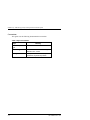
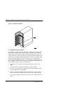
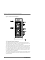
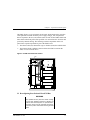
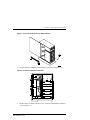
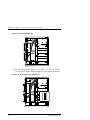
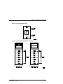
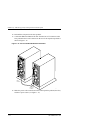
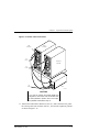
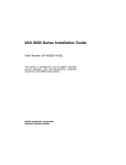
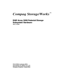
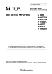
RAID Array 3000 Storage Subsystem
Expansion Pedestal Option
Installation Guide
EK–SM3KA–IG. A01
Digital Equipment Corporation
Maynard, Massachusetts
First Edition, January, 1998
The disclosure of this information does not grant to the user a license under any patents, pending
patents, trademarks, or copyrights or other rights of Digital Equipment Corporation, or of any
third party.
This software is proprietary to and embodies the confidential technology of Digital Equipment
Corporation.
Possession, use or copying of the software described in this publication is authorized only
pursuant to a valid written license from Digital Equipment Corporation or an authorized
sublicensor.
Digital Equipment Corporation makes no representation that the use of its products in the
manner described in this publication will not infringe on existing or future patent rights, nor do
the descriptions contained in this publication imply the granting of licenses to make, use, or sell
equipment or software in accordance with the description.
The following are trademarks of Digital Equipment Corporation:
DEC, DIGITAL, RAID Array 3000, StorageWorks, and the DIGITAL Logo.
All other trademarks and registered trademarks are the property of their respective owners.
©Digital Equipment Corporation 1998
Printed in USA
All Rights Reserved
Contents
Revision Record ............................................................................................... v
About This Guide .......................................................................................... vii
Chapter 1 Expansion Pedestal Option
1.0
Introduction........................................................................................................... 1–1
2.0
2.1
2.2
2.3
Product Description............................................................................................... 1–1
Expansion Pedestal Cabinet.............................................................................. 1–2
Expansion Pedestal Components ...................................................................... 1–4
Reconfiguring the SCSI Bus............................................................................. 1–5
Figure
1–1 Expansion Pedestal .....................................................................................1–2
1–2 Expansion Pedestal Slot Locations and ID Addresses .................................1–3
1–3 Expansion Pedestal Power Supplies ............................................................1–4
1–4 EMU Circuit Board Location......................................................................1–5
1–5 Remove Side Cover from Base Pedestal .....................................................1–7
1–6 Remove SCSI Bus Terminator....................................................................1–7
1–7 Disconnect SCSI Cable...............................................................................1–8
1–8 Connect SCSI Jumper.................................................................................1–8
1–9 Remove Connector Knockout Plate ............................................................1–9
1–10 Connect SCSI Cable .................................................................................1–10
1–11 Set Configuration Switch to 7...................................................................1–10
1–12 Configuration Switch................................................................................1–11
1–13 Reconfigured SCSI Bus Addresses............................................................1–11
1–14 Connect SCSI Cable Between Pedestals ...................................................1–12
1–15 Power Cable Connections .........................................................................1–13
1–16 Transfer Drives.........................................................................................1–14
EK–SM3KA–IG. A01
iii
Revision Record
This Revision Record provides a concise publication history of this guide. It lists the
revision levels, release dates, and summary of changes.
The following revision history lists all revisions of this publication and their effective
dates. The publication part number is included in the Revision Level column, with the
last entry denoting the latest revision. This publication supports the StorageWorks
RAID Array 3000 Expansion Pedestal Enclosure.
Revision Level
EK–SM3KA–IG. A01
EK–SM3KA–IG. A01
Date
January, 1998
Summary of Changes
Original release
v
About This Guide
This section identifies the audience of this guide and describes the contents (chapter-bychapter) and structure. In addition, this section includes a list of associated documents
and the conventions used in this guide.
Intended Audience
This guide is intended for installers and operators of the RAID Array 3000
storage subsystem. Installing the subsystem requires a general understanding of
basic SCSI terminology and product installation procedures.
Document Structure
This guide contains the following sections:
Chapter 1 Chapter 1 describes the Expansion Pedestal Option and how to install it.
1.0 Introduction Introduction provides a summaryof the content of this
guide.
2.0 Product Description Product Description describes the major
features of the expansion enclosure and its major components and how to
convert the UltraSCSI bus in the base pedestal from a split-bus to a through–
bus configuration.
Associated Documents
In addition to this guide, the following documentation is useful to the reader:
Table 1 Associated Documents
Document Title
StorageWorks RAID Array 3000 Storage Subsystem
Hardware User’s Guide
StorageWorks RAID Array 3000 Configuration and
Maintenance Guide
Installation Instructions for the RAID Array
Replacement Controller – SWXRC-03
EK–SM3KA–IG. A01
Order Number
EK–SMCPO–UG
EK–SMCS2–UG
EK–SMCPL–PN
vii
RAID Array 3000 Storage Subsystem Expansion Pedestal Option
Conventions
This guide uses the following documentation conventions:
Table 2 Style Conventions
Style
viii
Meaning
plain monospace
type
Text
boldface type
For the first instance of terms being
defined in text, or both.
italic type
For emphasis, manual titles, chapter
summaries, keyboard key names.
EK–SM3KA–IG. A01
About This Guide
Support and Services
Who to contact in the Americas
Information and Product Questions:
Local Sales Office / StorageWorks Hotline
1-800-786-7967
Installation Support:
Contact the DIGITAL Distributor where the
Storage Solution was Purchased / Local Digital
Sales Office.
DIGITAL Multivendor Customer Service (MCS):
Installation
Contact the DIGITAL Customer Support Center
(CSC).
Warranty
Contact the DIGITAL Customer Support Center
(CSC) for warranty service after solution is
installed and operating.
Remedial
Contact the DIGITAL Customer Support Center
(CSC)
Note: A Service Contract is recommended when
the equipment is out of warranty. Contact the
local DIGITAL Sales Office.
Customer Support Center (CSC)
1 800-354-9000
Who to contact in Europe
Information and Product Questions: Contact the DIGITAL Distributor or reseller
Installation Support and Installation: Contact the DIGITAL Distributor or reseller from
whom the Storage Solution was purchased.
For Warranty Service
See the Warranty Card packaged with the
product.
For Remedial Service
Contact the DIGITAL Distributor or reseller from
whom the Storage Solution was purchased.
Note: A Service Contract is recommended
when the equipment is out of warranty.
Who to contact in Asia Pacific
For all services, contact the DIGITAL Distributor or reseller from whom the
equipment was purchased
EK–SM3KA–IG. A01
ix
1
Expansion Pedestal Option
This guide describes how to install the Expansion Pedestal Option to expand the storage
capability of the RAID Array 3000 subsystem. The guide provides a product description
of the option and how to connect it to the base pedestal to create an enhanced storage
subsystem.
1.0
Introduction
This guide contains installation instructions needed to interface the expansion
pedestal to the base pedestal to create your expanded storage subsystem. The
guide is divided into the following sections:
• Product Description
• Expansion Cabinet and Components
• Reconfiguring the Base Pedestal UltraSCSI Bus
2.0
Product Description
The StorageWorks pedestal expansion option (Figure 1-1) is designed to expand
the storage capacity of the RAID Array 3000 subsystem. When connected to the
RAID Array 3000 base pedestal, the expansion option contains the basic components required to create a dual-pedestal storage array with a 16-bit, single-ended
Ultra-SCSI bus. The option enables a user to add up to seven 3½-inch SBBs to
create a 14-device storage array. The expanded array is controlled and operated
in an identical fashion as the base RAID Array 3000 subsystem.
EK–SM3KA–IG. A01
1–1
RAID Array 3000 Storage Subsystem Expansion Pedestal Option
Figure 1–1 Expansion Pedestal
2.1 Expansion Pedestal Cabinet
The expansion pedestal cabinet is a modular free-standing storage cabinet that is
completely self contained with dual fan-cooled power supplies, an internal UltraSCSI single-ended extender module, and an internal EMU circuit board. The
cabinet dimensions are the same as the subsystem base pedestal which houses the
controller and is normally installed within one meter of the base cabinet to facilitate the cable connections between the two units. Figure 1-2 identifies the expanded subsystem's SBB slots and they’re corresponding SCSI Id addresses. Figure 1-3 identifies the items on the rear panel power supplies. The characteristics
of the expansion pedestal cabinet are outlined below.
1–2
•
The storage device capacity of the expansion pedestal is seven 3½-inch
SBBs
•
The pedestal slots are numbered 0 through 6 from top to bottom
•
There are seven SCSI bus device addresses (target Ids) 8 through 14 which
can be assigned to the 3½-inch SBBs
•
There is a single 68-pin, VHDC female SCSI connector on the rear panel
which interconnects the SBB expansion pedestal to the controller pedestal
•
The rear panel contains an alarm switch and an external fault condition connector
EK–SM3KA–IG. A01
Chapter 1. Expansion Pedestal Option
•
The expansion pedestal contains two interchangeable fan-cooled ac power
supplies for redundant power
•
The expansion pedestal is equipped with an internal configuration switch
which selects one of the eight (0 through 7) subsystem configurations (set to
the correct configuration setting at the factory to properly integrate the expansion pedestal to the controller pedestal)
Figure 1–2 Expansion Pedestal Slot Locations and ID Addresses
SLOT 0
ID = 8
SLOT 1
SLOT 2
SLOT 3
SLOT 4
SLOT 5
SLOT 6
ID = 1 4
E XPAN S ION P ED ES TAL
300 0-19 A
EK–SM3KA–IG. A01
1–3
RAID Array 3000 Storage Subsystem Expansion Pedestal Option
Figure 1–3 Rear Panel Power Supplies
2.2 Expansion Pedestal Components
The expansion pedestal contains a 16-bit, wide/differential UltraSCSI bus, an
Environmental Monitor Unit (EMU), a SCSI bus extender module, and two universal 50/60 Hz, 100 – 240 Vac fan-cooled power supplies.
The single-ended UltraSCSI bus is factory-configured as one continuous bus that
runs along the backplane between the disk drive connectors and the internal cables. These cables connect the drives to the connectors located on the rear panel
of the expansion pedestal. The device addresses on the bus are set at the factory
by an internal configuration switch. When set to a specific position, the switch
controls the addresses of each SBB slot.
The SCSI bus extender module extends the allowable electrical length of the bus
to accommodate longer physical SCSI cable connections between the base and
expansion pedestals.
1–4
EK–SM3KA–IG. A01
Chapter 1. Expansion Pedestal Option
The EMU (Figure 1-4) is an internal circuit board, which monitors the operation
of the pedestal. The EMU monitors power supply voltages, fans, temperatures
that are reported to the user, and controls (turns on and off) the audible alarm and
status LED on the front panel of the pedestal. It is connected to the SCSI bus and
powered by internal cabling. The following external components on the rear
panel of the expansion pedestal are part of the EMU board:
•
The alarm switch (S1) that enables (up) or disables (down) the audible alarm
•
The External Fault Condition connector allows the EMU to monitor the
status of a user-selected device
Figure 1–4 EMU Circuit Board Location
EM U
3 000 -37
2.3 Reconfiguring Base Pedestal UltraSCSI Bus
WARNING
Only qualified service personnel should reconfigure the base pedestal. Dangerous voltages are
present within the subsystem. To prevent electrical shock, always turn the subsystem off and disconnect the power cords before removing the side
panel.
EK–SM3KA–IG. A01
1–5
RAID Array 3000 Storage Subsystem Expansion Pedestal Option
The RAID Array 3000 base pedestal is factory-configured for split-bus operation.
You must reconfigure the bus in the base subsystem from split-bus to a “throughbus” configuration prior to connecting the expansion cabinet to the base subsystem. The components needed to reconfigure the split-bus in the base subsystem
are included with your pedestal expansion kit option.
CAUTION
To prevent electrostatic discharge (ESD) from
damaging the controller, always wear an ESD
wrist strap connected to a suitable ground whenever you handle any of the electronic components.
Perform the following procedure to reconfigure the SCSI bus in the base pedestal
from a “split-bus” to a “through-bus” configuration:
1.
2.
Perform an inventory of the bus conversion items supplied with the pedestal
expansion kit option. The items should consist of:
•
SCSI bus jumper cable 17-04166-03
•
SCSI cable 17-04454-01
Quiesce the host bus by shutting down the host system.
CAUTION
To allow the UPS to supply power while the cache
is being flushed to disk, do not unplug the base
pedestal from the UPS.
1–6
2.
Unplug the base power cord from the wall outlet.
3.
Unplug the UPS power cord from the wall outlet, the UPS will now signal
the controller to flush the cache.
4.
Wait until the UPS shuts down completely (this may take several minutes).
5.
Power off the base pedestal and plug the UPS into the wall outlet.
6.
Remove the side cover from the base pedestal (Figure 1-5).
EK–SM3KA–IG. A01
Chapter 1. Expansion Pedestal Option
Figure 1–5 Remove Side Cover from Base Pedestal
8.
Remove the bus terminator from backplane connector J11 (Figure 1-6).
Figure 1–6 Remove SCSI Bus Terminator
R e m o v e Te rm in ato r
9.
3000-40
Remove the SCSI cable from device # 1 connector and backplane connector
J16 (see Figure 1-7).
EK–SM3KA–IG. A01
1–7
RAID Array 3000 Storage Subsystem Expansion Pedestal Option
Figure 1–7 Disconnect SCSI Cable
R em ove SC S I C a ble
3000- 41
10. Connect jumper cable 17-04166-03 between the backplane connector J11
and the backplane connector J16 (see Figure 1-8).
Figure 1–8 Connect SCSI Jumper
J11
J16
C onnect Jum pe r C able
1–8
3000- 42
EK–SM3KA–IG. A01
Chapter 1. Expansion Pedestal Option
11. Remove the “knock-out” plate located above the D1 OUT label on the rear
panel of the base pedestal (see Figure 1-9).
Figure 1–9 Remove Connector Knockout Plate
R em ove Kn ockou t
from D 1 O ut
3 0 0 0 -4 5
12. Connect cable assembly 17-04454-01 between the D1 OUT bulkhead opening and the device # 1 backplane connector (see Figure 1-10). Secure the
bulkhead connector by tightening the two 6-32 SEM screws.
EK–SM3KA–IG. A01
1–9
RAID Array 3000 Storage Subsystem Expansion Pedestal Option
Figure 1–10 Connect SCSI Cable
C o n n e c t S C S I C a b le
30 00 -43
13. Set the bus configuration switch to “7” (see Figures 1-11 and 1-12). Figure
1-13 shows the reconfigured SCSI bus addresses of the expanded subsystem.
Figure 1–11 Set Configuration Switch to 7
7
3 00 0- 44
1–10
EK–SM3KA–IG. A01
Chapter 1. Expansion Pedestal Option
Figure 1–12 Configuration Switch
Figure 1–13 Reconfigured SCSI Bus Addresses
EK–SM3KA–IG. A01
1–11
RAID Array 3000 Storage Subsystem Expansion Pedestal Option
14. Reinstall the side panel on the base pedestal.
15. Connect the HD68-to-HD68 SCSI cable from the D1 OUT connector on the
base pedestal to the D1 IN connector on the rear of the expansion pedestal as
shown in Figure 1-14.
Figure 1–14 Connect SCSI Cable Between Pedestals
Base
P e d es ta l
E xpa ns io n
P e de stal
3000-4 7
16. Make the power cable connections between the expansion pedestal, the UPS,
and the ac power source (see Figure 1-15).
1–12
EK–SM3KA–IG. A01
Chapter 1. Expansion Pedestal Option
Figure 1–15 Power Cable Connections
UPS
C on n ec to r
B as e
P e d e stal
AC
P o w er
Ex pa nsio n
P e de sta l
AC
Power
AC
Power
U PS
30 00-5 0
CAUTION
If you want to maintain the existing RAID level
configuration, three drives must be relocated from
the base pedestal to specific slots in the expansion pedestal as described in step 17.
17. Transfer the bottom three disk drives (slots 4, 5, and 6) from the base pedestal to the top three slot locations (slots 0, 1, and 2) in the expansion pedestal
as shown in Figure 1-16.
EK–SM3KA–IG. A01
1–13
RAID Array 3000 Storage Subsystem Expansion Pedestal Option
Figure 1–16 Transfer Drives from Base to Expansion Pedestal
ID = 8
ID = 8
ID = 9
ID = 9
ID = 10
ID = 10
ID = 11
ID = 11
ID = 8
ID = 12
ID = 9
ID = 13
ID = 10
ID = 14
B ase Pedestal
E xpansion P edes ta l
3 0 00 -4 6
18. Install the new drives in the remaining slots each pedestal to complete the
installation.
19. Power up the UPS and the two pedestals and then proceed to StorageWorks
RAID 3000 Configuration and Maintenance Guide to configure the expanded subsystem.
1–14
EK–SM3KA–IG. A01
Reader’s Comments
Manual Order Number:
EK–SM3KA–IG. A01
RAID Array 3000 Expansion Pedestal Option Installation Guide
Digital is committed to providing the best possible products and services. Since our manuals are
important components of our products, we value your comments, corrections, and suggestions
for improvements. Please take a few minutes to fill out and return this form, attaching additional
sheets, if needed. Thank you.
Manual Rating
Excellent
Good
Fair
Poor
Accuracy (correct presentation of facts)
Completeness (adequate information)
Clarity (easy to understand)
Organization (logical sequence of information)
Layout (easy to follow subject matter)
Indexing (easy to locate desired information)
[
[
[
[
[
[
[
[
[
[
[
[
[
[
[
[
[
[
[
[
[
[
[
[
]
]
]
]
]
]
]
]
]
]
]
]
]
]
]
]
]
]
Errors Noted (please include page, paragraph, table or figure number)
Return Address:
Name
Customer Research
Title
Phone
Response Center
Digital Equipment Corporation
334 South Street, SHR3-2/S27
Company
Street Address
Shrewsbury, MA 01545
Mail Stop
City
Country (if other than USA)
State
ZIP
]
]
]
]
]
]