1
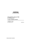
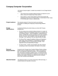
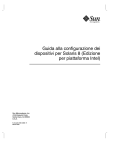
Getting Started
RAID Array 410 for Windows NT – Intel
Installation Guide
Order Number: EK–SMRAC-IG. C01
Digital Equipment Corporation
Maynard, Massachusetts
Third Edition, June 1996
The disclosure of this information does not grant to the user a license under any patents, pending
patents, trademarks, or copyrights or other rights of Digital Equipment Corporation, or of any third
party.
This software is proprietary to and embodies the confidential technology of Digital Equipment
Corporation.
Possession, use or copying of the software described in this publication is authorized only pursuant to
a valid written license from Digital Equipment Corporation or an authorized sublicensor.
Digital Equipment Corporation makes no representation that the use of its products in the manner
described in this publication will not infringe on existing or future patent rights, nor do the
descriptions contained in this publication imply the granting of licenses to make, use, or sell
equipment or software in accordance with the description.
© Digital Equipment Corporation 1996. All Rights Reserved
Printed in U. S. A.
The following are trademarks of Digital Equipment Corporation:
DEC, RAID Array 410, StorageWorks, and the Digital Logo.
Adaptec is a registered trademark of Adaptec Co.
Intel is a registered trademark of Intel Corporation.
Microsoft and MS-DOS are registered trademarks and Windows NT is a trademark of Microsoft
Corporation
Contents
Revision Record ...................................................................................................... v
About This Guide.................................................................................................. vii
Getting Started ...................................................................................................... ix
1 Unpacking and Setting Up Your RAID Array 410 Subsystem Components
1.1
1.2
1.3
1.4
1.5
1.6
1.6.1
1.6.2
1.7
1.8
1.9
Site Preparation .......................................................................................................... 1–1
Unpacking the RAID Array 410 (SWXRA-Yx) .......................................................... 1–2
Removing the RAID Array 410 from the Pallet .......................................................... 1–2
Placing the RAID Array 410 Enclosure ...................................................................... 1–4
Installing the SWXRC-04 Controller and Write-back Cache Module .......................... 1–4
Installing the PC (Program) Card in the Controller ..................................................... 1–4
PC (Program) Card Handling Precautions................................................................ 1–5
Installing PC (Program) Card in Controller ............................................................. 1–5
Connecting the Controller to Computer ...................................................................... 1–6
Installing Additional Disk SBBs in the StorageWorks Enclosure ................................ 1–6
Charging the RAID Array Controller Write-Back Cache Batteries .............................. 1–7
2 Host Adapter Installation
2.1
2.1.1
2.1.2
2.2
2.3
2.4
2.4.1
2.4.2
2.5
2.6
Install the Host Adapter .............................................................................................. 2–1
Preparing to Install the Host Adapter ....................................................................... 2–2
Installing the Host Adapter...................................................................................... 2–2
Installing the Subsystem ............................................................................................. 2–3
Configuration Utilities................................................................................................ 2–5
Loading the Adapter Driver for Use with Windows NT .............................................. 2–5
Windows NT Not Installed on System..................................................................... 2–5
Windows NT Previously Installed ........................................................................... 2–6
Installing the Device Driver (HSZDISK.SYS) ............................................................ 2–6
Verifying the System Recognizes the Host Adapter .................................................... 2–7
3 Installing and Using the RAID Manager for Windows NT
3.1
3.2
3.3
3.4
3.5
3.6
3.6.1
3.6.2
3.6.3
3.6.4
3.6.5
3.6.6
RAID Manager for Windows NT................................................................................ 3–1
Overview: Installing and Using the RAID Manager for Windows NT......................... 3–1
Installing the RAID Manager Software ....................................................................... 3–2
Setting Controller Communications............................................................................ 3–2
Setting the Controller Configuration ........................................................................... 3–3
Creating an Initial Configuration ................................................................................ 3–5
Displaying Physical/Logical View of System .......................................................... 3–5
Practice Example: Creating a Single Disk................................................................ 3–7
Practice Example: Creating a Stripeset .................................................................... 3–8
Practice Example: Creating a Mirrorset ................................................................... 3–9
Practice Example: Adding a Spare Disk................................................................. 3–10
Practice Example: Deleting Storagesets ................................................................. 3–10
EK–SMRAC–IG. C01
iii
Getting Started - RAID Array 410 for Windows NT – Intel
3.7
Saving the RAID Configuration ............................................................................... 3–12
4 Completing your Configuration Setup under Windows NT
4.1
4.1.1
4.1.2
4.1.3
Completing Configurations under Windows NT ......................................................... 4–1
Verifying that hszdisk.sys Loaded........................................................................... 4–1
Completing a New RAID Array Configuration........................................................ 4–2
Changes to RAID Array Configuration ................................................................... 4–7
Appendix A Configuration Records – Blank Forms
Appendix B Accessing the Command Line Interpreter (CLI)
Figures
1–1
1–2
1–3
1–4
1–5
1–6
2–1
2–2
2–3
3–1
3–2
3–3
3–4
3–5
3–6
3–7
3–8
3–9
3–10
4–1
4–2
4–3
4–4
4–5
4–6
4–7
iv
Minimum Installation Clearance Measurements ......................................................... 1–1
Unpacking the RAID Array 410 ................................................................................. 1–3
Installation of Ramp on Shipping Pallet ..................................................................... 1–3
PC (Program) Card Slot Location............................................................................... 1–6
StorageWorks SCSI Bus Port and SCSI ID Assignment ............................................. 1–7
SWXSC-AA Components .......................................................................................... 1–9
Connecting SCSI Cable.............................................................................................. 2–3
SCSI Cable Connection to Controller (Single Controller) ........................................... 2–4
SCSI Cable Connection to Controller (Dual Controller) ............................................. 2–4
RAID Manager Main Window (Upper Portion) .......................................................... 3–2
The System ID Window ............................................................................................. 3–3
Controller Configuration Window (Upper Portion)..................................................... 3–4
Physical View ............................................................................................................ 3–6
Updated Physical View .............................................................................................. 3–7
Create Window .......................................................................................................... 3–7
Updated Physical View – Disk (JBOD) Added ........................................................... 3–8
Updated Physical View – Stripeset Added.................................................................. 3–9
Updated Physical View – Mirrorset Added............................................................... 3–10
Delete Window ........................................................................................................ 3–11
How The hszdisk Entry Appears When It Loads Successfully .................................... 4–1
How the hszdisk Entry Appears When It Fails To Load.............................................. 4–2
Disk Administrator Screen Display............................................................................. 4–3
Partition Pull-Down Menu.......................................................................................... 4–5
Create Primary Partition Window............................................................................... 4–5
Tools Pull-Down Choices........................................................................................... 4–6
Format Menu.............................................................................................................. 4–7
EK–SMRAC–IG. B01
Revision Record
This Revision Record provides a concise publication history of this manual. It lists the manual
revision levels, release dates, and reasons for the revisions. It also describes how the changes
to affected pages are marked in the manual.
The following revision history lists all revisions of this publication and their effective dates.
The publication part number is included in the Revision Level column, with the last entry denoting the latest revision. This publication supports the StorageWorks RAID Array 410 Subsystem.
Revision Level
Date
Summary of Changes
EK–SMRAC–IG. A01
February 1996
Initial Release
EK–SMRAC–IG. B01
April 1996
Updates
EK–SMRAC–IG. C01
June 1996
Updates
EK–SMRAC–IG. C01
v
About This Guide
This section identifies the audience of this guide and describes the contents (chapter by chapter) and structure.
In addition, this section includes a list of associated documents and the conventions used in this guide.
This guide provides the following:
•
Description of how to unpack and assemble the RAID Array 410 Subsystem
•
How to install the Host Adapter board into your Intel-based system.
•
Installing and using the RAID Array 410 Manager for Windows NT.
•
Configuring the RAID Array using the RAID Array 410 Manager.
Audience
This guide is intended for administrators and system integrators of StorageWorks RAID Array
410 Subsystems. Installing the StorageWorks RAID Array 410 Subsystem requires a general
understanding of RAID concepts, Windows NT, and product installation procedures
Document Structure
This guide contains the following chapters:
Chapter 1: Unpacking and Setting Up Your RAID Array 410 Subsystem Components
This chapter describes how to unpack and place the Office Expansion RAID Enclosure. The
chapter also describes how install the SWXRC-04 RAID controller and its PC (Program) card,
and how to recharge the write-back cache batteries.
Chapter 2: Host Adapter Installation
This chapter describes the steps required to install the host adapter in your Intel-based system.
Chapter 3: Installing and Using the RAID Array 410 Manager for Windows NT
This chapter describes how to install and use of the RAID Array 410 Manager for Windows
NT. The chapter also describes how to create your initial configuration.
Chapter 4: Completing your Configuration Setup under Windows NT
This chapter describes how to use Disk Administrator in Windows NT to complete the installation.
EK–SMRAC–IG. C01
vii
Getting Started - RAID Array 410 for Windows NT – Intel
Appendix A: Configuration Record
This appendix contains blank forms that may be used to provide a record of your system configuration.
Appendix B: Accessing the Command Line Interpreter (CLI)
This appendix contains procedures to access the RAID Array controller (SWXRC-04) Command Line Interpreter (CLI).
Associated Documents
In addition to this guide, the following documentation is useful to the reader:
Table 1 Associated Documents
Document Title
Order Number
SWXSC-AA Office Expansion RAID Enclosure User’s Guide
SWXRC RAID Array Controller User’s Guide
RAID 410 Manager for Alpha/Intel User’s Guide
EK-SMCPD-UG
EK-SMCS1-UG
AA-QU63A-TE
Conventions
This guide uses the following documentation conventions:
Table 2 Style Conventions
viii
Style
Meaning
boldface monospace type
plain monospace type
italic type
To be input by the user
Screen text
For emphasis, manual titles, utilities, menus, screens, and filenames
EK–SMRAC–IG. B01
Getting Started
This section provides an overview for preparing and installing the RAID Array 410 for Windows NT in your Intelbased system. Detailed information is contained in Chapters 1 through 5.
Thank you for purchasing a StorageWorks RAID Array 410 Subsystem. You should have received the following:
•
StorageWorks RAID Array 410 Manager for Windows NT platform kit
•
StorageWorks RAID Array 410 Subsystem (SWXRA-Yx)
NOTE
• Installing the StorageWorks RAID Array 410 Subsystem
requires a technical understanding of the following:
• Intel-based Computer System
• RAID array concepts
• Windows NT
• Basic hardware installation procedures
• Or, contact your supplier or service representative for installation assistance.
The major steps for installing and setting up the StorageWorks RAID Array 410 Subsystem
include the following:
1. Performing the pre-installation steps listed below.
2. Unpacking and locating the RAID Array 410 Subsystem, installing the SWXRC-04
RAID Array controller, PC (Program) card, and write-back cache module, if they have
not been installed, and charging the write-back cache module batteries. (Chapter 1)
3. Unpacking and installing the host adapter in your computer system and connecting the
host adapter to the RAID controller. The host adapters that qualified to be used are:
• SWIA3-BB (Model AHA-2744W) for Intel-based EISA systems (Chapter 2)
• SWXA3-BC (Model AHA-2944W for Intel-based PCI systems (Chapter 2)
4. Installing the RAID Array 410 Manager for Windows NT (Chapter 3)
5. Configuring the communications port settings (Chapter 3)
6. Creating an Initial Configuration (Chapter 3)
7. Completing the Installation under Windows NT (Chapter 4)
EK–SMRAC-IG. C01
ix
Getting Started - RAID Array 410 for Windows NT – Intel
Installation “Checklist”
This section expands upon the preceding steps to provide a “checklist” or “roadmap” to assist
you during the installation process. Detailed procedures are provided in subsequent chapters
in this guide. Depending upon your specific configuration requirements, however, you may
not need to perform all the tasks identified:
1. Perform the pre-installation steps listed below (see this Getting Started chapter).
2. Plan your configuration: This means “mapping out” how you are going to set up your
single disks (JBODs), Stripesets, Mirrorsets, and RAIDsets in your RAID Array. (Useful
tools for this purpose are the configuration record sheets provided in Chapter 3 and the
Appendix of this guide.)
3. Unpack and locate the RAID Array 410 Subsystem. This includes:
•
Positioning the RAID Array subsystem
•
Installing the SWXRC-04 RAID Array controller, if it has not already been installed.
This also includes the controller’s PC (Program) card, and the write-back cache
module (Chapter 1)
•
Connecting the RAID Array maintenance port to the system using the serial cable
(Chapter 1)
• Charging the write-back cache module batteries (Chapter 1)
4. Unpack and install the host adapter in your system, connect it to the RAID Array, and
verify it is recognized by your system. This guide covers the following host adapters
models:
•
5.
6.
7.
8.
9.
Host adapter for an Intel-based system (Chapter 2)
− SWIA3-BB (Model AHA-2744W) for Intel-based EISA systems
− SWXA3-BC (Model AHA-2944W for Intel-based PCI systems
Install the RAID Array 410 Manager for Windows NT software (Chapter 3).
Set the Controller communications parameters (Chapter 3).
Create an initial configuration (Chapter 3).
Record your RAID configuration (Chapter 3).
Complete your RAID configuration using Windows NT Disk Administrator (Chapter 4).
Pre-installation Steps:
Before starting your installation, follow these pre-installation steps:
•
•
•
•
Back up your system files using your normal procedure.
Verify the availability of user-supplied hardware and software.
Inventory the contents of the StorageWorks RAID Array 410 Subsystem platform kit.
Inventory the contents of the StorageWorks RAID Array 410 Subsystem.
Perform a System Backup
Follow normal procedures to backup your system before installing the subsystem.
x
EK–SMRAC-IG. C01
Getting Started
Verify User-Supplied Hardware and Software (System Requirements)
The StorageWorks RAID Array 410 Subsystem requires the following user-supplied hardware and software:
• Intel-based PCI or EISA system with an available PCI or EISA slot (depending upon the
host adapter used)
• The associated system hardware manual(s)
• Appropriate tools to service your computer
• The Windows NT operating system – Version 3.51
Inventory the StorageWorks RAID Array 410 Subsystem Platform Kit Components
The Storage Works RAID Array 410 Platform Kit provides the following components:
•
•
•
•
•
•
•
•
One of the following host adapters:
− SWIA3-BB (Model AHA-2744W) for Intel-based EISA systems
− SWXA3-BC (Model AHA-2944W for Intel-based PCI systems
SCSI cable, with a right-angle high-density 68-pin connector on one end and a
straight high-density 68-pin connector on the other (BN21K-05)
PC (Program) Card for SWXRC-04
Media for RAID 410 Manager and host adapter drivers
RAID 410 Manager for Alpha/Intel User’s Guide (AA-QU63A-TE)
This Getting Started – RAID Array for Windows NT – Alpha/Intel Installation Guide
Release Notes containing version-specific instructions for system installation
RAID Array 410 Controller Firmware License Keys
The StorageWorks RAID Array 410 Subsystem (SWXRA-Yx) provides the following components:
•
•
•
•
•
•
•
•
•
The StorageWorks Storage Expansion Enclosure
The SWXSC-AA Office Expansion RAID Enclosure User’s Guide
The StorageWorks RAID Array 410 controller (SWXRC-04)
The SWXRC RAID Controller User’s Guide
Disk drive(s)
Serial cable (RJ12 to 9-pin serial) for connecting the maintenance port of the RAID
controller to the serial port of your system, PC, or maintenance terminal
9-pin to 25-pin adapter
Power Cable
Enclosure keys
NOTE
Retain the Firmware License Keys information in a safe
place. They are required if it becomes necessary to reinitialize the RAID Array Controller. Information for use is in the
SWXRC-04 RAID Controller User’s Guide.
EK–SMRAC-IG. C01
xi
1
Unpacking and Setting Up Your RAID Array 410
Subsystem Components
This chapter describes the site preparation and unpacking procedures for the RAID Array 410 Subsystem. It
also describes the procedure to recharge the controller write-back cache batteries.
1.1
Site Preparation
Before installing the enclosure, make sure that adequate space is available in front of the enclosure for opening the front door (19 inches clearance) and around the enclosure for adequate airflow. See Figure 1–1 for specific space requirements.
Figure 1–1 Minimum Installation Clearance Measurements
EK–SMRAC–IG. C01
1–1
Getting Started - RAID Array 410 for Windows NT – Intel
1.2
Unpacking the RAID Array 410 (SWXRA-Yx)
The RAID Array 410 is packed in a corrugated carton attached to a wooden shipping pallet,
as shown in Figure 1–2A. Unpack the unit as follows:
NOTE
Before unpacking the equipment, inspect the shipping carton for
signs of external damage. Report any damage to the local carrier
and to your sales representative.
1. Remove the shipping straps (Figure 1–2A).
2. Remove the top cover (Figure 1–2B).
3. Remove the ramp from the top of the shipping carton (Figure 1–2B) and set it aside for
subsequent use in moving the RAID Array 410 off the pallet.
4. Remove the two foam cushions from the top of the RAID Array 410 container
(Figure 1–2B).
5. Remove the sealed cardboard box packed beside the subsystem unit. It contains a cable
and documentation.
6. Remove the cardboard carton surrounding the RAID Array 410 (Figure 1–2B).
7. Remove the plastic barrier bag (Figure 1–2C).
8. Once the RAID Array 410 is exposed (Figure 1–2D), examine the equipment for any apparent damage. Report any such problems immediately to your sales representative.
1.3
Removing the RAID Array 410 from the Pallet
Use the following procedure to remove the RAID Array 410 from the shipping pallet:
WARNING
Serious personnel injury can result if correct safety precautions
are not taken during the removal procedure.
We recommend that three people perform the task of unloading
the RAID Array 410 Array from its shipping pallet. Failure to use
sufficient personnel can result in personnel injury and equipment
damage.
CAUTION
Do not drop the RAID Array 410 array from a height of more than
two inches, as serious structural damage to the enclosure can result.
1. Attach the ramp to the shipping pallet by fitting the lip of the ramp into the groove on the
pallet, as shown in Figure 1–3.
2. Lift the lock lever on each front caster to its up position so that the RAID Array 410 enclosure can be moved.
1–2
EK–SMRAC–IG. C01
Chapter 1. Unpacking and Setting Up Your RAID Array 410 Subsystem Components
Figure 1–2 Unpacking the RAID Array 410
Figure 1–3 Installation of Ramp on Shipping Pallet
EK–SMRAC–IG. C01
1–3
Getting Started - RAID Array 410 for Windows NT – Intel
3. Grasping the sheet metal base assembly, carefully lift the rear of the RAID Array 410
enclosure over the “hump” in the center of the pallet and then roll the RAID Array 410
enclosure off the pallet and down the ramp to the floor. If any further lifting of the RAID
Array 410 is required, grasp the sheet metal base assembly on the side and lift it carefully.
4. Retain the shipping container and all packing materials.
1.4
Placing the RAID Array 410 Enclosure
Use the following procedure to move the enclosure to its designated site:
WARNING
To prevent damage to the RAID Array and injury to personnel,
make sure to provide a clear path for the casters.
1. Roll the enclosure to the desired location.
2. If required, engage the lock on each front caster to prevent the enclosure from moving.
1.5
Installing the SWXRC-04 Controller and Write-Back Cache Module
Unlock the enclosure, if necessary, using the keys provided. If the SWXRC-04 RAID Array
controller and the write-back cache module have not been installed in your StorageWorks
enclosure, you should install them at this time. Do so by referring to Chapter 3, Installing
the Storage Subsystem, in the SWXRC RAID Array Controller User’s Guide
(EK-SMCS1-UG), included with the subsystem.
If your system is to be configured for dual-redundant controller operation, install the second
controller and associated components at this time . Refer to Chapter 3, Installing the Storage
Subsystem, in the SWXRC RAID Array Controller User’s Guide (EK-SMCS1-UG).
NOTE
Review the information contained in any Release Notes included
with the system. The Release Notes contain version-specific information, including controller configuration notes. Retain the Release Notes for future reference.
1.6
Installing the PC (Program) Card in the Controller
CAUTIONS
Follow these precautions and PC (program) card handling guidelines when installing or replacing the card. Install the (PC) program
card in the SWXRC-04 RAID controller after the controller has
been installed in a properly grounded SWXSC-AA cabinet. Otherwise, damage to the card may result.
The PC (program) card electrostatic discharge (ESD) shield must
remain installed over the card during controller operation to protect
it from electrostatic discharge that may cause the contents of the
card to be damaged.
1–4
EK–SMRAC–IG. C01
Chapter 1. Unpacking and Setting Up Your RAID Array 410 Subsystem Components
Follow these electrostatic discharge (ESD) precautions when handling the PC (program)
card.
•
Keep the PC (program) card in its original carrying case unless installing it.
•
Do not twist or bend the card.
•
Do not touch the contacts.
•
Keep out of direct sunlight.
•
DO NOT immerse the card in water or chemicals.
•
Always push the eject button to remove the card (see Figure 1–4).
•
A properly worn and attached ESD strap is required for installation and removal of the
card.
1.6.1 PC (Program) Card Handling Precautions
•
Obtain and attach an ESD wrist strap to your wrist. Make sure the strap fits snugly on your
wrist.
•
Plug (or clip) the other end to your cabinet's grounding stud (or other chassis grounding
point).
•
Remain grounded while working with the PC (program) card.
•
Remove the ESD connection from the cabinet ground stud or other chassis grounding
point.
•
Remove the ESD wrist strap from your wrist.
1.6.2 Installing PC (Program) Card in Controller
Refer to Figure 1–4 for the location of the PC (program) card slot, the eject button, and the
Operator Control Panel (OCP) LEDs on the controller.
For clarity, the ESD shield is not shown in the illustration. The ESD shield attaches to the
controller and covers the exposed edge of the PC (program) card and the PC (program) card
eject button.
Use the following procedure to install the PC (program) card:
1. Unsnap and remove the ESD shield covering the PC (program) card opening. The ESD
shield covers the card opening and the card eject button. The ESD shield is secured to the
controller with two “push/pull” fasteners. To remove the ESD shield, gently pull both
fastener shafts outward, approximately one-eighth inch and remove the ESD shield.
2. While holding the controller RESET depressed, insert the PC (program) card (label
side up). The card eject button extends when the card is fully inserted.
NOTE
Keep the RESET button depressed while inserting the card to
minimize the possibility of transients damaging the card contents
and also to ensure that the controller reinitializes when the button
is released.
EK–SMRAC–IG. C01
1–5
Getting Started - RAID Array 410 for Windows NT – Intel
3. Replace the ESD shield over the PC (program) card. To do so, first ensure the ESD
shield fastener shafts are extended outward, away from the contact surface of the ESD
shield. Place the ESD shield over the PC card and eject button and insert the ESD shield
fastener clasps in their mounting holes on the controller chassis. Then, gently push the
fastener shafts inward, approximately one-eighth inch, to engage the fastener clasps.
Figure 1–4 PC (Program) Card Slot Location
1.7
Connecting the Controller to Computer
Follow the steps below to connect the RAID Array 410 controller to a communications
(serial) port on your Intel-based system.
1. Locate the connecting cable that came with the RAID subsystem. It has an RJ12 connector (similar to some telephone plugs) on one end and a 9-pin serial connector on the other
end.
2. Plug the RJ12 connector into the maintenance port on the RAID Array 410 controller
(see Figure 1–4).
3. Plug the serial connector into an available 9-pin serial port on your Intel-based system. If
your system does not have a 9-pin serial port, use the 9-pin to 25-pin adapter supplied
with your StorageWorks RAID Array 410 Subsystem. Note which serial port you use,
because you will need that information when using the RAID 410 Manager program to
set the communications parameters.
1.8
Installing Additional Disk SBBs in the StorageWorks Enclosure
You may install additional disk SBBs in the StorageWorks enclosure at this time. To improve performance and reliability, we recommend that you install additional SBBs in the
StorageWorks enclosure from left to right, bottom to top (as viewed facing the front of the
enclosure). Doing so improves reliability by permitting you to create RAIDsets that span
more than one controller channel. Also, because more than one channel (bus) is being used,
throughput is improved.
1–6
EK–SMRAC–IG. C01
Chapter 1. Unpacking and Setting Up Your RAID Array 410 Subsystem Components
To install an SBB, hold it in both hands, insert it into the guide slots, and firmly push it into
the shelf until the mounting tabs snap in place. Installing the SBBs in this sequence distributes the SBBs among the SCSI ports of the RAID Array 410. Figure 1–5 shows a layout of
the SCSI bus ports and corresponding SCSI ID assignments in the enclosure. Refer to
Chapter 3, Configuration Rules and Restrictions, in the SWXSC-AA Office Expansion RAID
Enclosure User Guide (EK-SMCPD-UG), included with your system.
Figure 1 –5 StorageWorks SCSI Bus Port and SCSI ID Assignment
1.9
Charging the RAID Array Controller Write-back Cache Batteries
The Write-back Cache Module contains batteries that may have discharged since the time the
controller was factory-installed. If you place the controller into operation and attempt to initiate RAID commands when the battery charge is low, performance may be degraded. For
more information on this subject, refer to the manual, SWXRC RAID Array Controller User’s
Guide (EK-SMCS1-UG).
We recommend that you wait until the batteries are fully charged before placing the RAID
Array into operation.
We suggest you take this opportunity now to recharge the batteries. This is accomplished by
doing the following:
1. Install the power cable by routing the power cable through the cable access holes at the
bottom of the enclosure. Connect the female end of the power cable to the StorageWorks
enclosure’s AC Power Entry Controller, located in the lower portion of the enclosure (see
Figure 1–6).
2. Connect the other end of the power cable into a 110/220 VAC line voltage source (the
power supply automatically senses the voltage level and will work with either voltage).
EK–SMRAC–IG. C01
1–7
Getting Started - RAID Array 410 for Windows NT – Intel
3. Apply power to the controller, by using the power switch on the AC Power Entry Controller. You should hear a momentary audible tone (beep), and see the indicator LEDs illuminate. In addition, the controller reset button (see Figure 1–4) contains a green LED, which
should flash at approximately 1 Hz. For additional information, refer to the SWXRC RAID
Array Controller User’s Guide (EK-SMCS1-UG) and the SWXSC-AA Office Expansion
RAID Enclosure User’s Guide (EK-SMCPD-UG), included with these systems.
Power on the RAID Controller. The batteries should be fully recharged within six hours.
NOTE
As an alternative to waiting six hours, you may proceed now with
the installation and getting started steps described in subsequent
chapters of this manual. Then, when you perform the steps described in Chapter 4, Installing and Using the RAID Array 410
Manager for Windows NT, you will be able to check the status of
the batteries. This is described in Section 4.4, Setting Controller
Communications. If the battery status shows “good,” you may then
continue, and create your configuration.
1–8
EK–SMRAC–IG. C01
Chapter 1. Unpacking and Setting Up Your RAID Array 410 Subsystem Components
Figure 1–6 SWXSC-AA Components (Cabinet removed for clarity)
EK–SMRAC–IG. C01
1–9
2
Host Adapter Installation –
Intel-based System
In preparing your array for first time use, you need to connect your Intel-based system to the RAID subsystem
through the host adapter board. This chapter, along with your system and the associated StorageWorks RAID
Array 410 Subsystem manuals, provides instructions for preparing and installing the host adapter and the subsystem enclosure, and installing the appropriate drivers on the computer system..
CAUTION
The Host Adapters listed below are the only ones that, to date, are
qualified for use with StorageWorks RAID 410. The revision level
of the qualified boards are listed in the Check List document (EKSM1CU-CC) included in the StorageWorks RAID Array 410 Manager for Windows NT platform kit. Only boards with the listed revision levels should be used.
2.1
Install the Host Adapter
The host adapter is a SCSI-2 fast wide (16-bit) differential host adapter. Two versions of the
adapter are available and are discussed in this chapter, depending upon whether your computer is an EISA- or PCI- based system:
Table 2−
−1 RAID Array 410 Qualified Adapters
Adapter
Firmware
Revision
BIOS Revision
Family
Manager
Set
NT V3.51 Driver and
Date
SWXA3−BC
AHA−2944W
PCI
927000−01 A
or B
927201−00 A
or B
V 1.16
V1.20
AIC78XX.SYS
8/14/95
SWIA3−BB
2744W
EISA
909900−01 A
549306−00D
V2.11
V2.1
ARROW.SYS
3/13/96
The respective adapter installs in either your EISA- or PCI-based computer. In doing so, the
adapter connects your computer to the StorageWorks RAID Array 410 Subsystem through
the connecting SCSI cable.
EK–SMRAC–IG. C01
2–1
Getting Started - RAID Array 410 for Windows NT – Intel
You need the following before you begin:
• The appropriate host adapter (SWIA3-BB or SWXA3-BC). Use precautions to protect the
board from static discharge.
• Your computer system hardware manual
• Host adapter User’s Guide
• Appropriate tools to service your computer
• The SCSI cable (BN21K-05), with a right angle high density 68-pin connector on one end
and a straight high density 68-pin connector on the other
• Media labeled RAID 300, 400 Series WNT Intel Drivers (contains the HSZDISK.SYS
driver)
Refer to your computer system manual for any additional reference information on installing
a host adapter.
2.1.1 Preparing to Install the Host Adapter
Before installing the adapter in your host system, take precautions to protect the board from
electrostatic discharge.
CAUTION
To protect the board from static discharge, always use proper ESD
procedures. In addition, do not remove the board from its antistatic protective cover until you are ready to install the adapter.
Install the host adapter by performing the following steps:
1. Shut down your operating system.
2. When the system has halted, power down the host computer and all attached peripherals.
Disconnect power cables from the host computer.
WARNING
Failure to remove power from the host computer and peripherals
can introduce a personal hazard, or can result in damage to the
host computer or loss of stored data.
2. Open the computer to gain access to the motherboard, and locate an appropriate available
slot to install the adapter. Refer to your computer system manual for assistance in how to
gain access to the mother board and for identifying the appropriate slot in which to install
the adapter. Refer to your host adapter user manual for any guidelines or restrictions regarding slot selection for the adapter.
2.1.2 Installing the Host Adapter
The following steps must be performed to successfully install the host adapter:
1. Install the host adapter board in your computer; the board connector is held in place with
the screw you removed from the blank panel. Ensure that the board end plate metal tab
aligns in the computer chassis opening properly; otherwise the adapter will not seat
properly.
2. Replace your host computer covers; refer to your host computer manual for additional information, if necessary.
2–2
EK–SMRAC–IG. C01
Chapter 2. Host Adapter Installation – Intel-Based System
Connect the SCSI cable to the host adapter as shown in Figure 3–1.
3. The adapter is now physically installed. Later in the installation process, you will power
on your system and load the appropriate software for the required host adapter drivers.
Figure 2–1 Connecting SCSI Cable
2.2
Installing the Subsystem
1. Unlock the RAID Array Enclosure, if necessary, using the keys provided, and open the
enclosure front door.
2. Turn off AC power to the enclosure.
3. Install the SCSI cable between the host system and the RAID Controller.
•
•
Route the right angle connector end of the cable under the SWXRA-Yx Subsystem
enclosure and up through the front access hole closest to the connector on the RAID
controller.
Install the connector with the cable dressed to the right by firmly pushing it onto the
mating connector on the controller’s trilink connector. For a single controller configuration (see Figure 3–2), the other side of the trilink contains a terminator. For dual
controller configurations, one trilink contains a terminator and is connected to the
trilink on the other controller (see Figure 3–3) through an interconnecting SCSI cable
(BN21L-0B).
EK–SMRAC–IG. C01
2–3
Getting Started - RAID Array 410 for Windows NT – Intel
Secure the SCSI cable to the trilink on the controller by tightening the two screws on
the cable connector.
Figure 2–2 SCSI Cable Connection to Controller (Single Controller)
Figure 2–3 SCSI Cable Connection to Controller (Dual Controller)
2–4
EK–SMRAC–IG. C01
Chapter 2. Host Adapter Installation – Intel-Based System
4. Connect the power cable to the storage enclosure if it has not yet been installed. Do so by
connecting the female end of the power cable to the RAID Controller power controller located at the lower right front corner of the array. Plug the power cable into a 110/220
VAC line voltage source (the power supply automatically senses the voltage level and
will work with either voltage).
5. If you have not already applied power to the RAID Controller for up to 6 hours, as described in Chapter One of this manual, do so at this time. Doing so will recharge the
write-back cache batteries that may have discharged since the time they were factoryinstalled. The batteries should be fully recharged in the time specified. If you attempt to
initiate any RAID commands when the batteries are not charged, performance may be degraded.
NOTE
We recommend that you wait until the batteries are fully charged
before placing the RAID Array into operation. If you place the controller into operation and attempt to initiate RAID commands when
the battery charge is low, performance may be degraded. For
more information, refer to Chapter 1, Unpacking and Setting Up
Your RAID Array 410 Subsystem Components, in this guide.
2.3
Configuration Utilities
Some PCI- or EISA-system environments may require that you run configuration utilities
after installing the adapter. Be sure to consult your system documentation to verify if your
EISA- or PCI-based system requires you to run such configuration utilities (e.g., EISA configuration utility).
If such utilities need to be run, follow the instructions described in your system documentation.
Adapter-specific software that is required during this process is included in your adapter
package. Utilize only the adapters and software supplied with the Windows NT platform kit
as these are tested and certified to function with the SWXRC-04 RAID Controller.
2.4
Loading the Adapter Driver for Use with Windows NT
The software drivers used by Windows NT for the adapter can be loaded in one of two ways,
depending upon whether Windows NT is already loaded on your system. If Windows NT is
not install, perform paragraph 2.4.1 followed by 2.4.2. If Windows NT is already installed,
perform only paragraph 2.4.2. It is important that the software drivers supplied with the platform kit are used in the final installation of the adapter.
2.4.1 Windows NT Not Installed on System
If Windows NT was not present on the system when the adapter was installed, you should
load Windows NT at this time. As part of its installation sequence, Windows NT will automatically determine that the adapter has been physically installed in the system. Windows
NT will then automatically load the appropriate Adaptec adapter driver from the Windows
NT CDROM.
EK–SMRAC–IG. C01
2–5
Getting Started - RAID Array 410 for Windows NT – Intel
After Windows NT is installed, replace the device driver and install the device driver with
the one on the enclosed Windows NT disk.
2.4.2 Windows NT Previously Installed
If Windows NT was already present on the system when the adapter was installed, you need
to load the appropriate Adaptec adapter driver at this time. The Adaptec driver is contained
on the Adaptec Windows NT diskette.
To install the drivers, follows these steps:
1. Log into the Windows NT system with Administrator privileges.
2. Click on the Windows NT Setup icon in the main program group.
3. Select the Options menu in the Windows NT Setup window.
4. Select the Add/Remove SCSI Adapter function.
5. Click on the Add button in the dialog box.
6. A warning message is displayed; click on the OK button in the Confirm box.
7. From the list of adapters on the display, scroll to the end of the list, and select Other.
You may have to click on the list to reveal all of the options including the "Other" option. The Insert Disk window appears.
8. Insert the Adaptec Family Manager set diskette for Windows NT into your system's
floppy drive.
9. Type, for example: A:\winnt\3_5 and Click OK. Windows NT Setup momentarily
displays a window and then displays the Select OEM Option window.
10. Click OK to select the driver entry displayed in the Select OEM Option window. The
Select SCSI Adapter Option window appears.
11. Click Install to add the selected driver displayed in the Select SCSI Adapter Option window. The SCSI Adapter Setup Window appears.
12. Click Close to close the SCSI Adapter Setup Window.
13. Restart your system for the new driver to take effect.
2.5
Installing the RAID 300, 400 Series WNT Device Driver (HSZDISK.SYS Driver)
Locate the diskette labeled RAID 300, 400 Series WNT Intel Drivers. It contains the
HSZDISK.SYS driver.
Install the HSZDISK.SYS driver by performing the following steps:
1. Insert the RAID 300, 400 Series WNT Intel Drivers diskette into your floppy drive.
2. From Windows NT, click on command prompt in the Main program group.
3. Type the drive letter corresponding to your floppy drive (e.g., A:).
4. Change to the i386 sub-directory by typing the following command: CD \i386
5. Type the following command:
hszinstl drive_letter:\NT_root_directory
2–6
EK–SMRAC–IG. C01
Chapter 2. Host Adapter Installation – Intel-Based System
where:
“drive_letter” and “NT_root_directory” correspond to the root path of your
Windows NT system files on your system (e.g., hszinstl c:\winnt35).
6. The installation process copies the driver into the correct subdirectory and creates the
necessary Registry entries.
2.6
Verifying the System Recognizes the Host Adapter
Part of your computer’s start-up sequence (self-test and sizing checks) includes identifying
and displaying the names of the adapters installed in your system. The displays are in the
form of momentary screen displays during the start up sequence. You may utilize these momentary screen displays to verify that the system recognizes the installed adapter.
The device driver is now installed. Reboot your system now to load the driver.
Although it is not a necessary step in the Getting Started process, you may want to restart
your computer at this time and verify that the system recognizes the installed adapter.
Congratulations!
You may now proceed to "Installing and Using the RAID Array 410 Manager for Windows
NT," Chapter 3 this guide. Each time you reboot your system, following the completion of
"Creating RAIDsets," your Adaptec adapter will be ready for use with your system.
EK–SMRAC–IG. C01
2–7
3
Installing and Using the RAID Manager for
Windows NT
This chapter contains instructions for installing the RAID Manager software, configuring the system, and creating an initial configuration. This chapter also contains sheets for recording your configuration.
NOTE
The procedures in this chapter assume that the write-back cache
module batteries have been fully recharged, as described in
Chapter 1 of this guide. If you have not yet recharged your writeback cache batteries, you should do so at this time.
3.1
RAID Manager for Windows NT
The RAID Manager for Windows NT is a graphical user interface that facilitates configuring
and monitoring your RAID 410 subsystem.
Some capabilities of the manager include:
•
•
•
•
•
Creates single-disk units, RAID 0 (Stripesets), RAID 1 (Mirrorsets), RAID 0+1, and
RAID 5/3 (RAIDsets), and Spares.
Examines and modifies LUN parameters
Examines and modifies controller parameters
Monitors the addition and removal of disk drives from the array
Permits you to identify hot-spare drives that the system can use for automatic LUN reconstruction
Additional information regarding the RAID Manager for Windows NT is contained in the
manual, RAID 410 Manager for Alpha/Intel User’s Guide, (AA–QU63C–TE). For additional
background information regarding RAID and RAIDsets, refer to the manual, SWXRC RAID
Array Controller User’s Guide (EK–SMCS1–UG).
3.2
Overview: Installing and Using the RAID Manager for Windows NT
The steps required to Install and run the RAID Manager for Windows NT include the following:
•
Install the RAID Manager software on your computer system. This can be the system to
which the RAID Array 410 is attached, or it can be on a different Windows NT system.
•
Set the communications parameters required by the maintenance port on the SWXRC-04
controller.
EK–SMRAC–IG. C01
3–1
Getting Started - RAID Array 410 for Windows NT – Intel
3.3
•
Identify the controller as Model SWXRC-04.
•
Set up your initial RAID configuration using the RAID Manager.
Installing the RAID Manager Software
Locate the diskette, RAID 300, 400 Series for Windows NT RAID Manager, and insert it in
your disk drive.
Access Program Manager in Windows NT.
From the Program Manager, click on File and select Run from the pull-down menu.
At the Run command line, enter the name of the disk drive you inserted the disk in, followed
by this command: SETUP.EXE (i.e., A:\SETUP.EXE)
Doing so will load the RAID Manager software in your system, creating the necessary directories and icons. The default directory into which the software is loaded is RAID (e.g.,
C:\RAID).
3.4
Setting Controller Communications
The following procedures set the communications parameters for the serial link to the
SWXRC-04 maintenance port and identify the controller as SWXRC-04. To do so, perform
the following steps:
1. Click on the RAID Manager icon to access the RAID Manager. Doing so opens the
RAID Manager main window (see Figure 3–1). The main window contains five pulldown menu choices: File, View, Configuration, Settings, and Help.
Figure 3–1 RAID Manager Main Window (Upper Portion)
2. From the RAID Manager main window, click on Settings. This opens the Settings pulldown menu, which provides a number of choices including: Controller Communications, Fault Notification, System ID, Select Physical View, Physical View Preferred,
Logical View Preferred, and Password.
3. Select System ID.
The System ID window contains two fill-in boxes, as shown in Figure 3−2. Verify that
the field labeled System Name for the 6 channel RAID Controller identifies SWXRC-04
as the 6-channel RAID Controller. If not, type: SWXRC-04 in that field. Click OK when
you finish.
3–2
EK–SMRAC–IG. C01
Chapter 3. Installing and Using the RAID Array 410 Manager for Windows NT
Figure 3−
− 2 The System ID Window
4. At the RAID Manager main window, again click on Settings. This time, from the list of
choices in the Settings pull-down menu, select Controller Communications.
The Controller Communications window opens. At the Controller Communications window, make the following selections:
•
Choose the COM port (COM1, COM2, COM3, etc.) used to connect to the
SWXRC-04 maintenance port.
•
For Baud Rate, choose 9600 from the list of choices.
•
For the Connect interval, choose Continuous from the list of choices.
5. When finished making your choices, click on Connect at the Controller Communications window. The RAID Manager returns you back to the RAID Manager main window. Note that the narrow status bar that extends across the window (about one third of
the way from the top) has changed color from red to green, if you have connected successfully.
3.5
Setting the Controller Configuration
At the RAID Manager main window, click on the Configuration pull-down menu. The
Configuration pull-down menu provides the following choices: Create Storageset, Delete
Storageset, Modify, Controller, Configure from File, Delete All Storagesets, Controller
Firmware Load.
Select the choice, Controller. For our example, Figure 3–2 shows the upper portion of the
Controller Configuration Window.
Make the following two selections in the Controller Configuration Window:
• Select “A” for Cache Policy; this sets cache policy “A” mode. Cache policy A mode
(the default) provides write-back caching. Refer to the SWXRC RAID Array Controller
User’s Guide (EK-SMCS1-UG) for more information regarding caching and cache policy.
EK–SMRAC–IG. C01
3–3
Getting Started - RAID Array 410 for Windows NT – Intel
Select the choice, “D” for Host Functionality; this sets the controller to operate in Windows NT mode. This choice is required for the controller to operate correctly with Windows NT. Refer to the release notes for this product for more information.
•
Go to the bottom of the window and enter a value of 5 for the Cache Flush
Timer/Timers.
NOTE
It is mandatory that you select choice “D” for Host Functionality for
the SWXRC-04 controller to operate correctly with Windows NT. It
is also mandatory that the Cache Flush Timer/Timers be set to 5.
Click on OK after making the above selections.
Figure 3–3 Controller Configuration Window
At this point, your initial set up procedure is complete. You may now configure your system
using the RAID Manager graphical user interface. The RAID Manager graphical user interface facilitates the configuration process for you.
NOTE
You may not be able to create RAIDsets or mirrorsets if the writeback cache batteries are not fully charged.
To check controller battery status, click on the Controller button at
the left of the window. Doing so brings up the Controller Status
display, which includes the battery status. When the battery status
shows “good,” you may continue and create your initial configuration.
3–4
EK–SMRAC–IG. C01
Chapter 3. Installing and Using the RAID Array 410 Manager for Windows NT
To help you get started, and to familiarize you with the manager, we have provided simplified practice examples for setting up an initial configuration. (Your display screens may look
slightly different from those shown here, depending upon the version of your RAID Manager
software.) Complete instructions for using the manager are contained in the manual, RAID
410 Manager for Alpha/Intel User’s Guide, (AA-QU63C-TE), included with the system.
NOTE
The RAID Manager graphical user interface facilitates configuring
your system. However, the configuration process is not finished
until you complete the steps described in Chapter 4, Completing
Your Configuration Setup under Windows NT.
You may use the examples in the following sections to practice setting up your configuration. The examples shown describe how to configure a disk, a Mirrorset, Stripeset, and a
Spare disk. Configurations other than those described are set up in manner similar to the examples shown. When you have finished with the examples, you may delete the practice configuration.
3.6
Creating an Initial Configuration
The following steps describe creating an initial configuration for your subsystem.
NOTES
If you have not already done so, you may wish to take this opportunity now to plan how you are going to configure your system using disks (JBODs), Stripesets, Mirrorsets, RAIDsets, or combinations. This will allow you to better make use of the examples given.
For background information relative to the above terms, refer to
the SWXRC RAID Array Controller User’s Guide (EK-SMCS1-UG),
especially Appendix C, Working with RAIDsets.
The procedures described in this section are summary in nature.
For more information, refer to the manual, RAID 410 Manager for
Alpha/Intel User’s Guide (AA-QU63C-TE).
3.6.1 Displaying Physical/Logical View of System
The RAID Manager allows you to view your configuration in either a physical view or a
logical view. In our examples, we use the physical view. Select physical view by performing
the following steps:
1. Activate the RAID Manager by clicking on the RAID Manager icon (typically accessed
from the Windows NT Program Manager).
Doing so brings up the RAID Manager main window (see Figure 3–1). (While the window is being displayed, the screen momentarily displays the message: Please Wait.
Scanning Your System.
2. Click on the Settings pull-down menu. From the Settings pull-down menu choices,
choose Physical View Preferred (for our examples) from the choices offered.
EK–SMRAC–IG. C01
3–5
Getting Started - RAID Array 410 for Windows NT – Intel
3. Return to the main window and again click on the Settings pull-down menu. This time,
from the choices offered, choose Select Physical View and be sure to include SWXRC04 in the choice, so that the correct enclosure type will be displayed in the physical view.
4. Click on the Show Detail button to cause the physical view to be displayed.
For our example, the following image is displayed (see Figure 3–4). The image shows
one disk in the enclosure, at the lower left corner.
Figure 3–4 Physical View
NOTE
The number of disks in the display shown may not match the actual number of disks installed in the cabinet. This is because the
RAID Manager has not yet been told to add any new disks to the
configuration. This is accomplished in the following steps.
5. At the window menu choices, click on the Configuration pull down menu.
6. Choose Modify from the choices listed.
The Modify window appears, and lists the following choices: Add Devices, Remove
Devices, and Change Devices.
7. Select (click on) Add Devices from the choices listed, then click on OK.
Doing so brings up a message screen that advises you: Please install the new devices into
your system, then press OK to have the controller scan for these devices.
8. You should add any additional disks at this time if you have not already done so. In this
example, we add six disks to make a total of seven disks in the enclosure.
When you have finished adding disks, click on OK. The RAID Manager scans the system for
any new devices, then displays the updated view of the system. Figure 3–4 shows the updated physical view (for our example) with seven disks displayed.
3–6
EK–SMRAC–IG. C01
Chapter 3. Installing and Using the RAID Array 410 Manager for Windows NT
Figure 3–5 Updated Physical View
3.6.2 Practice Example: Creating a Single Disk
Click on the Configure button near the top of the main window. Doing so displays three
configuration buttons in the right side of the window: Create, Modify, and CLI.
To create a single disk, perform the following steps:
1.
Click on the Create button.
The Create button opens and displays the Create window (see Figure 3–5). Use the
Create window to select from the following choices: SPARE, RAID 0 - Stripeset,
RAID 1 - Mirrorset, RAID 5/3 - Raidset, RAID 0+1, and Single Disk - JBOD.
CAUTION
EISA (SWIA3-BB) limitation:
If you are using an EISA SWIA3-BB (Adaptec 2744W) host system
adapter, you are limited to four target Ids and only LUN0 per target
ID. Multiple LUNs under a target ID is not supported. A maximum
of four storage sets are allowed with a different target ID for each
storage set.
Figure 3–6 Create Window
EK–SMRAC–IG. C01
3–7
Getting Started - RAID Array 410 for Windows NT – Intel
2. For this example, select Single Disk - JBOD and choose a target ID (by default you can
create up to eight logical units under a single ID). Click on OK.
The RAID Manager responds by displaying a message window advising you to click on
the disk we wish to use (in our physical view) for the single disk. In our example, we
select (click on) the disk in the lower, left corner of the physical view.
3. After selecting the disk, click on Create in the message window
The RAID Manager responds by updating the physical view (see Figure 3–7). The physical view now shows the lower left disk superimposed with the letter “J,” to indicate
JBOD (Single Disk). Note also that the status bar at the bottom of the window has been
updated to reflect the added component. Figure 3–7 Updated Physical View – Disk
(JBOD) Added
3.6.3 Practice Example: Creating a Stripeset
Click on the Configure button near the top of the main window, if necessary, to display the
three configuration buttons in the right side of the window: Create, Modify, and CLI.
To create a Stripeset, perform the following steps:
1. Click on Create.
The Create button opens and displays the Create window (see Figure 3–6). Use the Create window to select from the following choices of storageset types: SPARE, RAID 0 Stripeset, RAID 1 - Mirrorset, RAID 5/3 - Raidset, RAID 0+1, and Single Disk - JBOD
CAUTION
The EISA SWIA3-BB (Adaptec 2744W) is limited to one LUN per
target ID. You must choose a different target ID for each storage
set.
2. For this example, select RAID 0 - Stripeset. Then, in the Set Name box, supply (enter) a
name for the Stripeset. For our example, the name is “Stripe1”. Click on OK when finished.
3–8
EK–SMRAC–IG. C01
Chapter 3. Installing and Using the RAID Array 410 Manager for Windows NT
The RAID Manager responds by displaying a message window advising you to click on
at least two disks (in our physical view) to use for the Stripeset.
3. Select the disks to use for the Stripeset. In our example, we select (click on) the two
bottom disks disk in the lower, right corner of the physical view. When finished, click on
Create in the message window.
The RAID Manager responds by updating the physical view (see Figure 3–8). The physical view now shows the two Stripeset disks superimposed with the letter “0,” to indicate
RAID 0 - Stripeset. Note also that the status bar at the bottom of the window has been
updated to reflect the added component.
Figure 3–8 Updated Physical View – Stripeset Added
3.6.4 Practice Example: Creating a Mirrorset
Click on the Configure button near the top of the main window, if necessary, to display the
three configuration buttons in the right side of the window: Create, Modify, and CLI.
To create a Mirrorset, perform the following steps:
1. Click on Create.
The Create button opens and displays the Create window (see Figure 4–5). Use the Create window to select from the following choices of strongest types: SPARE, RAID 0 Stripeset, RAID 1 - Mirrorset, RAID 5/3 - Raidset, RAID 0+1, and Single Disk - JBOD.
CAUTION
The EISA SWIA3-BB (Adaptec 2744W) is limited to one LUN per
target ID. You must choose a different target ID for each storage
set.
EK–SMRAC–IG. C01
3–9
Getting Started - RAID Array 410 for Windows NT – Intel
2. For this example, select RAID 1 - Mirrorset, then, in the Set Name box, supply (enter) a
name for the Mirrorset. For our example, the name is “Mirr1”. Click on OK when finished.
The RAID Manager responds by displaying a message window advising you to click on
at least two disks (in our physical view) to use for the Mirrorset.
3. Select the disks to use for the Mirrorset. In our example, we select (click on) the three
remaining disks in the bottom row of the enclosure. When finished, click on Create in
the message window.
The RAID Manager responds by updating the physical view (see Figure 3–8). The physical view now shows the three Mirrorset disks superimposed with the letter “1,” to indicate RAID 1 - Mirrorset. Note also that the status bar at the bottom of the window has
been updated to reflect the added component.
Figure 3–9 Updated Physical View – Mirrorset Added
3.6.5 Practice Example: Adding a Spare Disk
Click on the Configure button near the top of the main window, if necessary, to display the
three configuration buttons in the right side of the window: Create, Modify, and CLI.
To create a spare by using the remaining disk in our example, (left, second row), perform the
following steps:
1. Click on Create.
The Create button opens and displays the Create window (see Figure 4–5). Use the Create window to select from the following choices of strongest types: SPARE, RAID 0 Stripeset, RAID 1 - Mirrorset, RAID 5/3 - Raidset, RAID 0+1, and Single Disk - JBOD.
3–10
EK–SMRAC–IG. C01
Chapter 3. Installing and Using the RAID Array 410 Manager for Windows NT
2. Choose (click on) Spare from the choices listed, then click on OK.
When the physical view window opens, click on the disk to be identified as a spare, then
Create.
3.6.6 Practice Example: Deleting Storagesets
To delete storageset elements, perform the following steps:
1. Select the Configuration pull down menu. The choices include: Create Storageset,
Delete Storageset, Modify, Controller, Configure from File, Delete All Storagesets,
Controller Firmware Load.
2. For this example, choose (click on) Delete Storageset from the choices listed.
The RAID Manager opens the Delete window (see Figure 3–10).
Figure 3–10 Delete Window
3. Select Mirr1 for the first storageset to delete in our example.
Doing so opens a message window to confirm the delete operation. The message window
asks if you are sure you want to delete the set and advises you to type yes to verify the
delete command.
4. Type yes in the message window to confirm your intent to delete, then click on OK.
Doing so causes the RAID Manager to delete the set and to update the physical view.
5. Continue to delete remaining Storagesets or single disks by returning to the main window, choosing the Configuration pull-down menu, and repeating the above steps to delete the remaining practice examples.
Congratulations!
You may now configure your system. Use the RAID 410 Manager for Alpha/Intel User’s
Guide (AA-QU63C-TE) and the skills learned during the practice examples to set up
your specific configuration. When finished, save your configuration for future reference,
then proceed to Chapter 5, Completing your Configuration under Windows NT, in this
guide.
EK–SMRAC–IG. C01
3–11
Getting Started - RAID Array 410 for Windows NT – Intel
NOTE
After saving (or recording) your configuration, you must reboot
your system, then use Windows NT Disk Administrator to complete the configuration under Windows NT. Doing so ensures that
Windows NT recognizes the partition/format configuration information.
You must also use Windows NT Disk Administrator to complete
the configuration under Windows NT when changes are made to
the configuration. This is described in Chapter 4, Completing your
Configuration Setup under Windows NT.
3.7
Saving the RAID Configuration
You may save your configuration information in two ways.
1. Access the RAID Manager File pull-down menu. From the choices listed, choose
Save. The RAID Manager saves the configuration information in a configuration
file. The file may be accessed later by selecting the Configuration pull-down menu,
then choosing the selection, Configure from File.
2. You may record your configuration on the sheets contained in this guide, to provide
a hard copy of your configuration information. Target and LUN information can be
found in the status bar below the physical view of the configuration (see Figure 3–7).
You have now completed the steps required to create an initial configuration for your controller using the RAID Manager. You must now complete the installation by referring to Chapter 5, Completing your Configuration Set Up under Windows NT. At this point, you may
wish to record your configuration for future reference. Additional worksheets are provided in
Appendix A for recording future new or modified configurations.
If you need information relative to accessing the Command Line Interpreter (to run maintenance or diagnostic programs), refer to Appendix B, Accessing the Command Line Interpreter
(CLI), in this guide.
3–12
EK–SMRAC–IG. C01
Chapter 3. Installing and Using the RAID Array 410 Manager for Windows NT
Record the information in the following table:
Date__________________
Name of RAIDset
EK–SMRAC–IG. C01
Type of RAIDset
Target
LUN
Disk(s) Used
3–13
4
Completing your Configuration Setup under
Windows NT
This chapter contains instructions for how to complete your configuration set up through Disk Administrator
under Windows NT.
4.1
Completing Configurations under Windows NT
In order for Windows NT to recognize new RAID Array 410 devices or changes to existing
configurations, you must reboot your system to restart Windows NT.
4.1.1 Verifying that hszdisk.sys Loaded
Prior to running Disk Administrator, verify that hszdisk recognizes the devices that you created in the RAID Array 410 Subsystem.
To verify hszdisk, follow these steps:
1. Find the Event Viewer in the Administrative Tools group and open it.
Look for an entry for hszdisk in the Event Viewer window.
If no entry for the hszdisk appears in the Event View window, go to Chapter 2 of this
guide and reinstall hszdisk.
If an entry for hszdisk appears with 0 in the Event column, similar to the screen shown in
Figure 4−1, the hszdisk loaded successfully and connected to at least one logical drive in
the RAID Array 410. Go on to Section 4.1.3 to complete the new array configuration.
Figure 4−
− 1 How The hszdisk Entry Appears When It Loads Successfully.
EK–SMRAC–IG. C01
4–1
Chapter 4. Completing Your Configuration Setup Under Windows NT
If an entry for hszdisk appears with a 1 in the Event column, similar to the screen shown
Figure 4−2, the hszdisk did not load successfully due to its not finding any logical
drives. If the hszdisk did not load successfully, go to Chapter 3 of this guide, and reconfigure the array. If after reconfiguring the array, hszdisk still fails to load, contact your
Sales Representative.
Figure 4−
− 2 How The hszdisk Entry Appears When It Fails To Load.
3. Close the Event Viewer when you finish verifying hszdisk.sys.
4.1.2 Completing a New RAID Array Configuration
The steps listed in this section are necessary to complete your RAID Array installation. This
section describes how to use Disk Administrator to complete a new configuration under
Windows NT. The instructions listed here are summary in nature. For additional information,
refer to your Windows NT documentation.
NOTE
To safeguard critical data, backup your system using normal
backup procedures before altering device partitions.
To begin, run Disk Administrator from within Windows NT by performing the following
steps:
1. Select Program Manager
2. Select Administrative Tools
3. Select Disk Administrator
4–2
EK–SMRAC–IG. C01
Getting Started - RAID Array 410 for Windows NT – Intel
NOTE
The first time you run Disk Administrator after adding new disks,
one or more message window(s) may appear asking you to confirm whether you want to have Disk Administrator provide its
“signature” on the new disks. Confirm doing so (by clicking on
Yes) in order to have Disk Administrator recognize these new
disks. For more information on this subject, refer to your Windows
NT documentation.
Figure 4–1 shows the partial screen display for a representative configuration.
Understanding the Disk Administrator Display
Disk Administrator creates a “Bar Chart” display of your disk configuration (see
Figure 4–3), The figure shows that Windows NT has named the various devices that were
created using the RAID Array 410 manager graphical user interface. Each disk device found
by Windows NT is given a name, e.g., Disk 0, Disk 1, etc. There should be an entry (device)
shown for each disk (JBOD) or storageset created.
Windows NT assigns disk names based on the order in which the system drivers “find” disks
during Windows NT boot. The RAID Array 410 uses a special disk class driver
(HSZDISK.SYS) that connects to all SWXRC-04 disks before any other disks present in the
system are connected. Therefore, the first entries in the Disk Administrator display
(see Figure 4–3) should represent all your RAID Array 410 Logical Disks.
Figure 4–3 Disk Administrator Screen Display
EK–SMRAC–IG. C01
4–3
Chapter 4. Completing Your Configuration Setup Under Windows NT
The figure also shows the corresponding free space for each entity. There should be an entry
(device) shown for each disk (JBOD) or storageset created.
Before proceeding, you should verify the following:
1. There should be an entry in the Disk Administrator display for each of your disks or
RAID Array 410 logical disks.
If there is not, you should go back and recheck your configuration. You may need to
verify either the logical or physical (or both) configuration of your RAID Array 410.
2. The capacity shown for each device should match the size of the physical disk or the
RAID Array 410 storageset.
NOTE
Disk Administrator displays the “usable” capacity of a RAIDset and
Mirrorset, not the combined total of the physical members.
If it does not, you should recheck the logical configuration for the RAID Array 410
and its members.
To complete your configuration under Windows NT, perform the following steps:
1. Create partitions as follows:
•
•
For each disk shown by first select (click on) the partition area that you wish to
create.
Then, click on the Partition pull-down menu. From the Partition pull-down
menu, choose Create (see Figure 4–4).
Doing so opens the Create window (see Figure 4–5).
NOTE
A disk cannot be accessed unless it contains at least 1 valid partition that was created under disk administrator.
4–4
EK–SMRAC–IG. C01
Getting Started - RAID Array 410 for Windows NT – Intel
Figure 4–4 Partition Pull-Down Menu
See Figure 4–5 Create Primary Partition Window
In the window, enter the size partition you want, then click on OK. (Depending upon
the partition size you choose, a message window may appear asking you to confirm
your selection.)
2. Continue to create new partitions until all disks have been partitioned.
3. Optional: Make disk logical names permanent.
The process of creating partitions assigns a logical name (the letter “C,” “D,” etc.) to
each partition. These letter assignments, under Windows NT, will normally “float.”
That is, they are subject to changing (after reboot), if the disk configuration changes.
EK–SMRAC–IG. C01
4–5
Chapter 4. Completing Your Configuration Setup Under Windows NT
You may, however, make these assignments “permanent.” (For more information on
this subject, you should consult your Windows NT documentation.) If you wish to
make the letter assignments “permanent,” access the Tools pull-down menu. From
the choices given, select Drive Letter then choose To Assign. This process must be
repeated for each partition (drive letter) that you wish to make “permanent.”
4. When you have created all your partitions, go back to the Partition pull down menu
and click on Commit Changes Now (see Figure 4–4).
A message window will then appear asking you to confirm that you wish to commit
these changes.
After confirming that you wish to commit the changes, a new message screen should
appear advising that the commit changes action was successful.
NOTE
A message window will appear following this step asking you if you
wish to save a copy of the configuration to a floppy. You may do
so at this time, as prompted by the screen display.
5. While still running Disk Administrator, click on the Tools pull-down menu, then
select Format (see Figure 4–6).
The Format menu choices (see Figure 4–7) allow you to choose either FAT or
NTFS. You must select one of these file system options for the disk to be usable.
You may also choose the Quick Format option. Select OK to begin the format process. For further information regarding these options, refer to your Windows NT
documentation.
A message window appears advising you when the formatting is complete.
NOTE
A third format, HPFS, is not an available choice under Disk Administrator. The HPFS format choice may only be made from a command prompt window. Refer to your Windows NT documentation
for more details on this subject.
Figure 4–6 Tools Pull-Down Choices
4–6
EK–SMRAC–IG. C01
Getting Started - RAID Array 410 for Windows NT – Intel
Figure 4–7 Format Menu
6. Continue to format each new partition until all partitions have been formatted.
7. When all partitions have been formatted, close Disk Administrator. At this point, the
configuration has been completed, and is recognized by Windows NT.
4.1.3 Changes to RAID Array Configuration
NOTE
To safeguard critical data, backup your system using normal
backup procedures before altering device partitions.
Do not alter partitions that contain important data.
When making changes to an existing RAID Array configuration, any existing disk partitions
to be changed (or removed) must first be deleted using Windows NT Disk Administrator.
After they have been deleted, you may use the RAID Array 410 Manager to create new Storagesets (refer to the RAID Array 410 Manager for Windows NT, to make the changes).
To remove disk partitions, run Disk Administrator from within Windows NT by performing
the following steps:
1. Select Program Manager
2. Select Administrative Tools
3. Select Disk Administrator
Delete the partitions you intend to change (or remove) by performing the following steps:
1. From Disk Administrator, select (click on) the partition you wish to delete.
2. Pull down the Partition menu.
3. Choose Delete, then continue.
4. Continue selecting and deleting the partitions until you have done so to all the partitions
you wish to change.
5. Go back to the Partition pull down menu and click on Commit Changes Now.
6. At this point all the disks you intend to reconfigure have been deleted from Windows
NT. You may now reconfigure the RAID Array using the RAID Array 410 Manager as
described in the manual RAID Array 410 Manager for Windows NT User’s Guide.
EK–SMRAC–IG. C01
4–7
Chapter 4. Completing Your Configuration Setup Under Windows NT
7. You now need to reboot your system for changes made thus far to be recognized by
Windows NT.
8. After rebooting, you need to perform the steps listed at the beginning of this chapter,
Section 4.1.1, Completing a New RAID Array Configuration, in order for the changes to
take effect.
9. After completing the steps described in Section 4.1.1, Completing a New RAID Array
Configuration, you are done.
4–8
EK–SMRAC–IG. C01
A
Configuration Records – Blank Forms
This contains copies of the table used in Chapter 3 to record the configuration of your system. If additional copies are required, these tables can be reproduced as necessary.
EK–SMRAC–IG. C01
A–1
Getting Started – RAID Array 410 for Windows NT – Intel
Date__________________
Name of RAIDset
A–2
Type of RAIDset
Target
LUN
Disk(s) Used
EK–SMRAC–IG. C01
Appendix A. Configuration Records – Blank Forms
Date__________________
Name of RAIDset
EK–SMRAC–IG. C01
Type of RAIDset
Target
LUN
Disk(s) Used
A–3
Getting Started – RAID Array 410 for Windows NT – Intel
Date__________________
Name of RAIDset
A–4
Type of RAIDset
Target
LUN
Disk(s) Used
EK–SMRAC–IG. C01
B
Accessing the Command Line Interpreter (CLI)
This chapter contains instructions for accessing the Command Line Interpreter (CLI). The CLI is used to access
various maintenance and diagnostic programs.
B.1
What is the CLI?
The Command Line Interpreter (CLI) is an alternate user interface for the RAID 410 controller. Using a connection between the controller’s maintenance port and your computer system’s communications port, the CLI can be used to enter commands, access various reports,
and run diagnostic tools. For additional information regarding these commands, reports, and
tools, refer to the SWXRC RAID Array Controller User’s Guide (EK-SMCS1-UG).
B.2
Accessing the CLI
NOTE
Before performing the following procedures, you must exit and
close the RAID Array 410 manager graphical user interface. This
is necessary to permit the serial data line and associated communications port on the computer system to run with the terminal
emulator program, as described below.
The CLI is accessed from your system’s Windows NT Terminal program (in the Accessories
group). The Terminal program uses the serial data line that connects the maintenance port on
a SWXRC-04 controller to your computer system communications port (Com1, Com2, etc.).
Although you may use a separate maintenance terminal, we recommend using the Terminal
program. Doing so simplifies the procedure because the serial data line already has been connected as part of your system installation procedure. You can also use most commerciallyavailable communications programs.
The Following procedures assumes your serial data line remains connected from the
SWXRC-04 controller maintenance port to the communications port on your computer system. Follow these procedures to access the CLI:
1. Start the communications program on your system.
2. Set the communications program to use the serial port (COM1, COM2, etc.) that is connected to the controller.
EK–SMRAC-IG. C01
B–1
Getting Started – RAID Array 410 for Windows NT –Intel
3. Set the communications parameters to:
•
•
•
•
9600 baud
8 bits
1 stop bit
No parity
4. From your communication program, issue a connect command to establish a connection
with the controller, and then press the Enter key. You should see the CLI prompt, which
looks similar to
SWXRC>
From this prompt, you may issue your CLI commands. For further information regarding
CLI commands, reports, etc., refer to the SWXRC RAID Array Controller User’s Guide (EKSMCS1-UG).
B–2
EK–SMRAC-IG. C01
Reader’s Comments
Manual Order Number:
EK–SMRAC–IG. C01
Digital is committed to providing the best possible products and services. Since our manuals are important
components of our products, we value your comments, corrections, and suggestions for improvements. Please take a
few minutes to fill out and return this form, attaching additional sheets, if needed. Thank you.
Manual Rating
Excellent
Accuracy (correct presentation of facts)
Completeness (adequate information)
Clarity (easy to understand)
Organization (logical sequence of information)
Layout (easy to follow subject matter)
Indexing (easy to locate desired information)
[
[
[
[
[
[
]
]
]
]
]
]
Good
[
[
[
[
[
[
]
]
]
]
]
]
Fair
Poor
[
[
[
[
[
[
[
[
[
[
[
[
Errors Noted (please include page, paragraph, table or figure number)
Most-Liked Features
Least-Liked Features
Suggestions for Improvement
Name
Phone
Return Address:
Title
Digital Equipment Corporation
Customer Research
Response Center
Company
Street Address
334 South Street, SHR3-2/S27
Shrewsbury, MA 01545
Mail Stop
City
Country (if other than USA)
State
ZIP
]
]
]
]
]
]
]
]
]
]
]
]