1
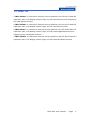
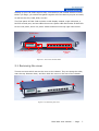
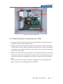
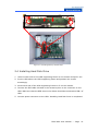
FWA-3180
Rackmount Internet Security
Platform with 8 Front LAN
Ports/ PCI Expansion Slot/
LCD Display
Advantech
Internet Security Platform
Copyright Notice
This document is copyrighted, 2004. All rights are reserved. The original
manufacturer reserves the right to make improvements to the products described in
this manual at any time without notice. No part of this manual may be reproduced,
copied, translated or transmitted in any form or by any means without the prior
written permission of the original manufacturer. Information provided in this
manual is intended to be accurate and reliable. However, the original manufacturer
assumes no responsibility for its use, nor for any infringements upon the rights of
third parties which may result from its use.
CE Notification
The FWA-3180, developed by Advantech Co., Ltd., has passed the CE test for
environment specifications when shielded cables are used for external wiring. We
recommend the use of shielded cables.
1st Edition
Printed in Taiwan
June 2004
FWA-3180 User Manual --- Page
II
Product warranty
Advantech warrants to you, the original purchaser, that each of its products will be
free from defects in materials and workmanship for two year from the date of
purchase.
This warranty does not apply to any products which have been repaired or altered
by persons other than repair personnel authorized by Advantech, or which have
been subject to misuse, abuse, accident or improper installation. Advantech
assumes no liability under the terms of this warranty as a consequence of such
events.
Because of Advantech’s high quality-control standards and rigorous testing, most of
our customers never need to use our repair service. If an Advantech product is
defective, it will be repaired or replaced at no charge during the warranty period. For
out-of-warranty repairs, you will be billed according to the cost of replacement
materials, service time and freight. Please consult your dealer for more details.
If you think you have a defective product, follow these steps:
1. Collect all the information about the problem encountered. For example, CPU
speed, Advantech products used, other hardware and software used, etc. Note
anything abnormal and list any on-screen messages you get when the problem
occurs.
2. Call your dealer and describe the problem. Please have your manual, product,
and any helpful information readily available.
3. If your product is diagnosed as defective, obtain an RMA (return merchandise
authorization) number from your dealer. This allows us to process your return more
quickly.
4. Carefully pack the defective product, a fully-completed Repair and Replacement
Order Card and a photocopy proof of purchase date (such as your sales receipt) in
a shippable container. A product returned without proof of the purchase date is not
eligible for warranty service.
5. Write the RMA number visibly on the outside of the package and ship it prepaid to
your dealer.
FWA-3180 User Manual --- Page
III
Packing List
Before installation, ensure that the following materials have been received:
• One FWA-3180 Internet Security Platform
• One box of accessories
• One CD-ROM for user manual (PDF file)
If any of these items are missing or damaged, contact your distributor or sales
representative immediately.
Technical Support and Sales Assistance
If you have any technical questions about the FWA-3180 or any other Advantech
products, please visit our support website at:
• http://www.advantech.com.tw/support
For more information about Advantech's products and sales information, please
visit:
• http://www.advantech.com.
FWA-3180 User Manual --- Page
IV
Contents
1. General Information....................................... 1
1.1 Introduction......................................................................... 2
1.2 Features................................................................................. 2
1 . 3 S p e c i f i c a t i on s . . . . . . . . . . . . . . . . . . . . . . . . . . . . . . . . . . . . . . . . . . . . . . . . . . . . . . . . . . . . . . . . . . . 2
1.4 Dimensions....................................................................4
1.5 Model List....................................................................5
2. System Setup............................................... 6
2.1 Removing the cover............................................................................. 7
2.2 Installing Central Processing Unit (CPU)...................................... 8
2.3 Installing Memory Module............................................................9
2.4 Installing Hard Drive........................................................................10
2.5 Installing Compact Flash...................................................11
2.6 Setting LAN Bypass function.........................................................12
Appendix A...................................................15
A.1 NAME-3180 Mother Board...............................................16
FWA-3180 User Manual --- Page
V
Figures
Figure 1-1: FWA-3180 dimensions................................................................... 4
Figure 1-2: Outlook of FWA-3180......................................................................... 4
Figure 2-1: Front view of FWA-3180.......................................................... 7
Figure 2-2: Removing the cover............................................................. 7
Figure 2-3: Top view of FWA-3180.......................................................... 8
Figure 2-4: Installing Central Processing Unit steps..................................... 9
Figure 2-5: Installing Memory Module steps.................................................. 10
Figure 2-6: Installing Hard Disk Drive steps............................................. 11
Figure 2-7: Installing Compact Flash steps.................................... 12
Figure 2-8: The illustration of LAN Bypass function.................... 12
Figure 2-9: LAN Bypass function jumps....................................... 13
FWA-3180 User Manual --- Page
VI
1
General Information
FWA-3180 User Manual --- Page
1
1.1 Introduction
Conceived as a powerful rackmount Internet Security platform, the FWA-3180 was
specifically designed for Internet secure connectivity. Designed with the Intel®
Pentium® 4 processor, it provides high performance and meets the requirements of
Internet security appliances. The system supports Compact Flash for OS and
Internet security applications. This avoids service disruption caused by hard disk
mechanical / magnetic failures. In addition, the FWA-3180 can support system
memory up to 2 GB DDR memory. Both Compact Flash and memory can be
accessed and replaced for software upgrades through an easily removable cover.
Designed with the Plug-and-Serve concept in mind, the FWA-3180 offers eight
10/100/1000 Mbps auto-sensing LAN ports in the front panel. There are two LED
Indicators which monitor power and HDD activities. For easy access, the front panel
has a 9-pin, RS-232 serial port for local system management, maintenance and
diagnostics. The FWA-3180 provides optional 3.5” IDE HDD and one PCI slot. It is
FCC and CE compliant. Please see the FWA-3180 user manual for more details.
1.2 Features
• 1U rackmount Internet security platform
• Socket 478 Intel® Pentium® 4
• One 32-bit/33 MHz PCI expansion slots
• Eight 10/100 Fast Ethernet or 10/100/1000 Gigabit Ethernet ports
• Console port for local setting
• Hard drive mounting bracket for 3.5” drive
• LCD display module
• LAN Bypass function
1.3 Specifications
• Processor System:
CPU: Intel Pentium 4 , 3.06G Hz
Max. Speed: 533/400 MHz FSB
L2 Cache: 512/256KB
Chipset: Intel 845GV, ICH4
BIOS: Award 2 Mb Flash
• Memory: Support DDR 266/200, Max. Capacity 2 GB, Socket 184-pin DIMM x 2
• Ethernet: 10/100 Fast Ethernet or 10/100/1000 Gigabit Ethernet, RJ-45 x 8
FWA-3180 User Manual --- Page
2
• Drive Bay: 3.5”HDD x1
• Management: Console RS-232 x1
• Cooling: Fan (15 CFM) x2, Blower x1
• Miscellaneous: Power Switch, 2 LED indicators for Power/HDD, CompactFlash
Socket x1, LCD Display Module x1
• Adapter Power Requirement:
Input: ATX PS, AC 90 ~ 264 V @ 47 ~ 63 Hz, full range
Output: 250W
• Operating Environment:
Operating: Temperature 0 ~ 40 °C (32 ~ 104 °F), Humidity 5 ~ 85 %
Non-Operating: Temperature -20 ~ 75 °C (-4 ~ 167 °F), Humidity 5 ~ 95 %
• Dimensions (W x H x D):
1U: 426 x 44.4 x 380 mm (16.7” x 1.7” x 14.9”)
• Weight: 4.5 Kg (9.9 lb)
FWA-3180 User Manual --- Page
3
1.4 Dimensions
Figure 1-1: FWA-3180 dimensions.
Figure 1-2: Outlook of FWA-3180
FWA-3180 User Manual --- Page
4
1.5 Model List
• FWA-3180 A: 1U rackmount Internet security platform, One 32-bit/33 MHz PCI
expansion slots, LCD display module, Eight 10/100 Fast Ethernet ports supporting
four LAN Bypass function.
• FWA-3180 B: 1U rackmount Internet security platform, One 32-bit/33 MHz PCI
expansion slots, LCD display module, Eight 10/100 Fast Ethernet ports.
• FWA-3180 C: 1U rackmount Internet security platform, One 32-bit/33 MHz PCI
expansion slots, LCD display module, Eight 10/100/1000 Gigabit Ethernet ports
supporting four LAN Bypass function.
• FWA-3180 D: 1U rackmount Internet security platform, One 32-bit/33 MHz PCI
expansion slots, LCD display module, Eight 10/100/1000 Fast Ethernet ports.
FWA-3180 User Manual --- Page
5
2
System Setup
FWA-3180 User Manual --- Page
6
Setting up your FW-3180 requires only a screwdriver and a small amount of time.
Before you begin, you should also gather together all of the device you plan to install,
as well as the CPU, RAM, HDD, and etc.
The front panel of FWA-3180 includes a LCD display module, eight LAN ports, a
RS-232 console port, and two LEDs where one is power LED and another is HDD LED.
On the rear panel, there is a power switch located on the top right hand corner.
Power switch
LCD display module
RS-232
Console
port
Eight LAN
ports
Figure 2-1: Front view of FWA-3180
2.1 Removing the cover
There are screws which secure the cover to the chassis. They are along the sides,
near the top. Remove them, and then slide the cover to the rear of the chassis.
Figure 2-2: Removing the cover
FWA-3180 User Manual --- Page
7
Two 15-CFM
cooling fan
Power supply
3.5” HDD Space
One PCI slot
Figure 2-3: Top view of FWA-3180
2.2 Installing Central Processing Unit (CPU)
1. Locate the 478-pin CPU ZIF socket on the motherboard. And pull the Socket
actuation lever to the 90-degree directly.
2. Position the CPU above the socket that its marked corner (golden cut edge on
the CPU upper corner) matches the base of the socket lever. Insert the CPU into
the socket. (Do not force the CPU into the socket.) Then push down the socket
lever to secure the CPU.
3. Apply the thermal tape to provide better heat conduction between your CPU and
cooling fan. Position the cooling fan on top of the CPU. Align and snap the four
hooks of the retention mechanism to the holes on each corner of the module
base.
4. Make sure the CPU fan power connector is plugged to the motherboard fan
power connector, than installing CPU is completed.
FWA-3180 User Manual --- Page
8
1.
2.
3.
4.
Figure 2-4: Installing Central Processing Unit steps
2.3 Installing Memory Module
Please note that FSB 533 Pentium 4 processor will support DDR333/DDR266
memory module and FSB 400 Pentium 4 processor will only support DDR266
memory module.
1. Unlock a DIMM socket by. Align the notch of the DIMM memory module to match
on the socket and insert the DIMM into the socket until the DIMM is properly
seated.
2. Press the retaining clips inward to lock the DIMM memory module. Installing
memory module is completed.
FWA-3180 User Manual --- Page
9
1.
2.
Figure 2-5: Installing Memory Module steps
2.4 Installing Hard Disk Drive
1. Unscrew each side of the HDD supporting frame on the chassis and pull it out.
2. Put the HDD above the HDD supporting frame and position the screws
accordingly.
3. Screw each side of the HDD supporting frame to fix on the chassis.
4. Connect the IDE cable included in the accessory box to the connector on the
HDD. Make sure that the RED wire on the ribbon should be connected to PIN 1 of
HDD.
5. Connect power connector to the HDD. Installing Hard Disk Drive is completed.
FWA-3180 User Manual --- Page
10
1.
2.
3.
5.
4.
Figure 2-6: Installing Hard Disk Drive steps
2.5 Installing Compact Flash
1. Position a CompactFlash disk accordingly in the CompactFlash disk socket and
push it inward. Installing CompactFlash disk is completed.
FWA-3180 User Manual --- Page
11
1.
Figure 2-7: Installing Compact Flash steps
2.6 Setting LAN Bypass function
FWA-3180 provides LAN Bypass function showed as Figure 2-8. When system shuts
down, LAN1-LAN2, LAN3-LAN4, LAN5-LAN6, LAN7-LAN8 will connect directly to
avoid network broken.
Network appliance
software
Network appliance
software
Rx Tx Rx Tx Rx Tx Rx Tx Rx Tx Rx Tx Rx Tx Rx Tx
Rx Tx Rx Tx Rx Tx Rx Tx Rx Tx Rx Tx Rx Tx Rx Tx
Rx Tx Rx Tx Rx Tx Rx Tx Rx Tx Rx Tx Rx Tx Rx Tx
Rx Tx Rx Tx Rx Tx Rx Tx Rx Tx Rx Tx Rx Tx Rx Tx
Figure 2-8: The illustration of LAN Bypass function
The jump "J4" allows you to set LAN Bypass function. (See J4 pins assignment in
APPENDIX A.1 NAME-3180 MOTHER BOARD)
FWA-3180 User Manual --- Page
12
Pins 1-3: Monitor network mechanism with watchdog timer
Pins 3-5: Turn off LAN Bypass
N. C.: Turn on LAN Bypass
Pins 2-4: Set LAN Bypass enable automatically when system shut down
Pins 4-6: Set LAN Bypass enable / disable via BIOS
2
4
6
J3-J6 : LAN Bypass Control
1
J3-J6
3
5
1-3 :WATCH DOG
(Default)
3-5 :LAN Bypass Off
2-4 :AUTO On
(Default)
4-6 :GPIO Control
N.C. :LAN Bypass On
Figure 2-9: LAN Bypass function jumps
When jumper keeps on pins 4-6, follow below steps to set LAN Bypass function via
BIOS.
1. Turn on FWA-3180 platform. Then hold down the <Delete> key during the boot
process to enter BIOS menu.
2. Move to "LAN Bypass Control" Item
3. Press <PageUp> or <PageDown> key to change the condition option of "LAN
Bypass Control" Item. Condition option [Enabled]: Set LAN Bypass function
enable. Condition option [Disabled]: Set LAN Bypass function disable.
4. Press <F10> to save and exit BIOS menu.
Figure 2-10: Setting LAN Bypass function from BIOS
FWA-3180 User Manual --- Page
13
A
Pin Assignments
APPENDIX
FWA-3180 User Manual --- Page
14
A.1 NAME-3180 Mother Board
1. CONNECTORS
CONNECTOR
DESCRIPTION
CN19 / CN22
Primary/ Secondary IDE Bus
CN1 / CN8-10/ CN14
FAN Speed Sense and function
CN23
GPIO Output Control
CN24
Floppy Connector
CN15 / CN17
Power, Reset and LAN Active
CN26
Parallel Port Connector
CN4 / CN5
USB Port Connector
CN29
PS/2 KB and Mouse Connector
CN7 / CN3 / CN6
Com Port Connector
CN12
VGA Connector
J1
Clear CMOS
J2
Intruder Function
J3-6
LAN Bypass Control
ATX
ATX Power Connector
FWA-3180 User Manual --- Page
15
2. PIN ASSIGNMENTS
PIN
NAME
CN3
CN24
CN19 / CN22
PIN
NAME
PIN
NAME
PIN
NAME
1
IDE_RST
2
GND
1
Vcc
2
INDEX#
3
D7
4
D8
3
Vcc
4
DRVSLT#
5
D6
6
D9
5
Vcc
6
DSKCHG#
7
D5
8
D10
7
9
11
13
15
17
D4
10
D3
12
D2
14
D1
16
D0
18
D12
D13
D14
D15
8
9
D11
10
11
13
15
17
12
DRVDEN0
14
GND
16
GND
18
WRTDALT#
WRTGATE#
20
NC
19
GND
20
TRACK0#
#RE0
22
GND
21
GND
22
WRTPRT#
23
#IOW
24
GND
23
GND
24
RDDATA#
25
#IOR
26
GND
25
GND
26
SIDESLT#
DAck
30
33
35
37
IR0
32
ADDR1
34
ADDR0
36
#CS0
38
DCD
1
GND
2
SIN
2
Vcc
3
SOUT
3
MSDAT
4
DTR
4
MSCLK
5
GND
5
GND
6
DSR
6
Vcc
7
RTS
7
KBDAT
8
CTS
8
KBCLK
9
RI
CN6
PIN
NAME
1
DCD
2
DSR
3
SIN
4
RTS
5
SOUT
6
CTS
7
DTR
8
RI
9
GND
GND
PIN
31
1
NC
CN17
29
NAME
PIN
NAME
NC
1
LAN5 LED
2
LAN5 LED
3
LAN6 LED
4
LAN6 LED
5
LAN7 LED
6
LAN7 LED
66DET
ADDR2
#CS1
7
39
#HD_ACT
40
GND
41
Vcc
42
Vcc
43
GND
44
NC
LAN8 LED
8
LAN8 LED
CN15
CN9
PIN
CN26
NAME
PIN
NAME
1
PANSWIN
2
Power SW
10
NC
NAME
3
#WG_RST
4
Reset SW
1
STB
2
#AFD
5
Vcc
6
Power LED
3
PD0
4
#ERR
7
5VSB
8
Standby
LED
1
Vcc
5
PD1
6
#SLIN
9
LAN1 LED
10
LAN1 LED
2
Vcc
11
LAN2 LED
12
LAN2 LED
3
Data-
13
LAN3 LED
14
LAN3 LED
4
Data-
15
LAN4 LED
16
LAN4 LED
5
Data+
17
Vcc
18
IDE LED
6
Data+
PIN
NAME
7
9
11
13
PIN
PD2
8
PD3
10
PD4
12
PD5
14
NAME
STEP#
GND
28
PIN
DRTSLT#
21
RDY
CN29
NAME
MTRON#
19
27
PIN
CN4 / CN5
PIN
NAME
GND
GND
GND
GND
15
PD6
16
GND
17
PD7
18
GND
CN12
19
#ACK
20
GND
PIN
21
Busy
22
GND
1
VGA_R
23
PE
24
GND
3
25
SLCT
26
GND
7
GND
NAME
8
GND
2
NC
9
GND
VGA_G
4
GND
5
VGA_B
6
NC
7
NC
8
V_SDAT
CN1 / CN8-10 /
CN14
NAME
PIN
10
NC
ATX
PIN
1
3
NAME
3.3V (+)
GND
PIN
2
4
9
GND
10
HSYNC
PIN
11
GND
12
VSYNC
1
NAME
GND
13
GND
14
V_SCLK
2
Power
NC
3
FANIO
NAME
3.3V (+)
5V (+)
15
GND
16
5
GND
6
5V (+)
7
GND
8
NC
J3-6
9
5V STB
10
12V (+)
PIN
FUNCTION
PIN
FUNCTION
11
3.3V (+)
12
12V (-)
1-3
2-4
13
GND
14
PS-ON
Watch dog
(Default)
AUTO ON
(Default)
15
GND
16
GND
3-5
LAN Bypass
OFF
4-6
GPIO
Control
NC
LAN Bypass
ON
17
GND
18
5V (-)
19
5V (+)
20
5V (+)
FWA-3180 User Manual --- Page
16