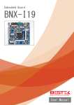
1
P4 Socket 478 Motherboard
IN845GVD
User’s Manual
http://www.bcmcom.com
Declaration
Rights:
No part of this manual, including but not limited to the products and software described in it, may
be reproduced, transmitted, transcribes, stored in a retrieval system, or translated in any form or by
any means without the expressed written permission from the manufacturer.
Products and corporate names appearing in this manual may or may not be registered trademarks or
copyrights of their respective companies and are used only for identification or explanation
purposes without intent to infringe.
z
Intel, Pentium® 4 are registered trademarks of Intel Corporation.
z
Microsoft and Windows® are registered trademarks of Microsoft Corporation.
z
Phoenix® and Award® are registered trademarks of Phoenix Technologies LTD..
Responsibility:
This manual is provided “As-Is” with no warranties of any kind, either expressed or implied,
including, but not limited to the implied warranties or conditions of this product’s fitness for any
particular purpose. In no event shall we be liable for any loss of profits, loss of business, loss of
data, interruption of business, or indirect, special, incidental, or consequential damages of any kind,
even the possibility of such damages arising from any defect or error in this manual or product.
We reserve the right to modify and update the user manual without prior notice.
WARNING:
Replace your system’s CMOS RAM battery only with the identical CR-2032 3V Lithium-Ion coin
cell (or equivalent) battery type to avoid risk of personal injury or physical damage to your
equipment. Always dispose of used batteries according to the manufacturer’s instructions, or as
required by the local ordinance (where applicable).
References:
This manual is created and written by BCM Technical Dept., but not limited, to the information
from the IN845GVD External Production Specifications, and IN845GVD Specifications. If any
comments, suggestions, or errors for this manual, please write an e-mail to [email protected].
Compliance & Certificate
Compliance & Certificate
ISO 9001 Certificate:
This device was produced in our plant with advanced quality system certified by DNV QA Ltd. in
according to ISO 9001. This Certificate is valid for:
DESIGN & MANUFACTURE OF MOTHERBOARD AND PERSONAL COMPUTERS.
CE Declaration:
CE marking is a visible declaration by the manufacturer or his authorized representatives that the
electrical equipment to which it relates satisfies all the provisions of the 1994 Regulations.
FCC Compliance:
FCC stands for Federal Communications Commission.
This product complies with FCC Rules Part 15 and has been tested, and complied with the EMI
rules by a certified body. In normal operation, there shall be no harmful interference caused by this
device nor shall this device accept any interference received, including interference that may cause
undesired operation of this product.
Year 2000 Compliance:
This product is test to be qualified to bear the NSTL Year 2000 Compliant logo. Year 2000
problem is mainly a problem of computer software (OS), and the hardware issue. With the support
of BIOS on motherboard, the Y2K problem can be thoroughly conquered.
Easy Installation
Ea s y Ins ta lla tio n
Easy Installation Steps
The following “Easy Installation” steps are for users
accustomed to the assembly of a computer system. For those
individuals requiring more specific information, please refer
to the more detailed descriptions located within the latter
chapters of this manual.
Note: You must keep your power cable unplugged until the
following installation steps are completed.
Getting Started
Touch a grounded metal surface to release static electricity
stored in your body before unpacking your motherboard. For
details please refer to Precaution.
Install the CPU by correctly aligning the CPU with the socket
478 as noted in the motherboard diagram. Once aligned,
press down on the CPU gently but firmly and lock it. Next,
install the 3.3 volt un-buffered DDR SDRAM into the 184
pin DIMM slots.
Plug in any peripheral card(s) that you want to be included in
the setup.
Plug in all cables included in the package except for the
power cord.
Please recheck all steps to ensure no mistakes have been
made and then plug in the power cord and turn on the power
to enter the BIOS setup, Chapter 3.
TABLE OF CONTENT
USER’S NOTICE
MANUAL REVISION INFORMATION
COOLING SOLUTIONS
CHAPTER 1 INTRODUCTION OF IN845GVD MOTHERBOARD
1-1 FEATURE OF MOTHERBOARD
1-2 SPECIFICATION
1-3 LAYOUT DIAGRAM & JUMPER SETTING
CHAPTER 2 HARDWARE INSTALLATION
2-1 HARDWARE INSTALLATION STEPS
2-2 CHECKING MOTHERBOARD'S JUMPER SETTING
2-3 INSTALL CPU
2-3-1 GLOSSARY
2-3-2 ABOUT INTEL PENTIUM 4 478-PIN CPU
2-4 INSTALL MEMORY
2-5 EXPANSION CARD
2-5-1 PROCEDURE FOR EXPANSION CARD INSTALLATION
2-5-2 ASSIGNING IRQ FOR EXPANSION CARD
2-5-3 INTERRUPT REQUEST TABLE FOR THIS MOTHERBOARD
2-6 CONNECTORS, HEADERS
2-6-1 CONNECTORS
2-6-2 HEADERS
2-7 STARTING UP YOUR COMPUTER
CHAPTER 3 INTRODUCING BIOS
3-1 ENTERING SETUP
3-2 GETTING HELP
3-3 THE MAIN MENU
3-4 GENERAL CONFIGURATION
3-5 ADVANCED CONFIGURATION
3-6 PRIMARY IDE DRIVES/ SECONDARY IDE DRIVES
3-7 INTEGRATED PERIPHERALS
3-8 POWER MANAGEMENT
3-9 PCI/PNP CONFIGURATION
3-10 HARDWARE MONITOR
3-11 RESTORE MANUFACTURE SETTINGS
3-12 EXIT
23
23
24
26
28
30
32
34
36
37
38
38
Mechanical Draw
39
i
1
1
2
3
4
5
7
7
9
9
10
11
12
12
12
13
13
13
17
22
USER’S NOTICE
COPYRIGHT OF THIS MANUAL BELONGS TO THE MANUFACTURER. NO PART OF THIS
MANUAL, INCLUDING THE PRODUCTS AND SOFTWARE DESCRIBED IN IT MAY BE
REPRODUCED, TRANSMITTED OR TRANSLATED INTO ANY LANGUAGE IN ANY FORM OR BY
ANY MEANS WITHOUT WRITTEN PERMISSION OF THE MANUFACTURER.
THIS MANUAL CONTAINS ALL INFORMATION NECESSARY TO USE OF RX845GL/IN845GL
MOTHER-BOARD AND WE DO ASSURE THIS MANUAL CONTENT AS MANY INFORMATION AS
POSSIBLE, BUT WE RESERVE RIGHT TO CHANGE, UPDATE ANYTIME WITHOUT PRIOR NOTICE.
MANUFACTURER PROVIDES THIS MANUAL “AS IS” WITHOUT WARRANTY OF ANY KIND,
AND WILL NOT BE LIABLE FOR ANY INDIRECT, SPECIAL, INCIDENTIAL OR
CONSEQUENTIAL DAMAGES (INCLUDING DAMANGES FOR LOSS OF PROFIT, LOSS OF
BUSINESS, LOSS OF USE OF DATA, INTERRUPTION OF BUSINESS OF ANY KIND ALIKE).
PRODUCTS AND CORPORATE NAMES APPEARING IN THIS MANUAL MAY OR MAY NOT BE
REGISTERED TRADEMARKS OR COPYRIGHTS OF THEIR RESPECTIVE COMPANIES, AND
THEY ARE USED ONLY FOR IDENTIFICATION OR EXPLANATION AND TO THE OWNER’S
BENEFIT, WITHOUT INTENT TO INFRINGEMENT.
Manual Revision Information
Reversion
1.0
Revision History
First Release
Mar. 2005
Item Checklist
5
5
5
5
5
IN845GVD Mainboard
□
Cable for USB Port 3/4 (Optional)
Date
Cable for IDE/Floppy
CD for Mainboard Driver Utilities/ Manual
IN845GVD Quick Installation Guide
ATX I/O Shield
1
Intel Pentium 4 Processor Family
Cooling Solutions
As processor technology pushes to faster speeds and higher performance, thermal management becomes
increasingly crucial when building computer systems. Maintaining the proper thermal environment is
key to reliable, long-term system operation. The overall goal in providing the proper thermal
environment is keeping the processor below its specified maximum case temperature. Heatsinks induce
improved processor heat dissipation through increased surface area and concentrated airflow from
attached fans. In addition, interface materials allow effective transfers of heat from the processor to the
heatsink. For optimum heat transfer, Intel recommends the use of thermal grease and mounting clips to
attach the heatsink to the processor.
When selecting a thermal solution for your system, please refer to the website below for collection of
heatsinks evaluated and recommended by Intel for use with Intel processors. Note, those heatsinks are
recommended for maintaining the specified Maximum T case requirement. In addition, this collection is
not intended to be a comprehensive listing of all heatsinks that support Intel processors.
For vendor list of heatsink and fan, please visit :
http://developer.intel.com/design/Pentium4/components/index
2
Chapter 1
Introduction of IN845GVD Motherboard
1-1 Feature of motherboard
The IN845GVD motherboard has been updated to support Intel latest Celeron D and Intel Pentium 4
Processor in 478 Pin Package up to 533Mhz FSB Processor with Hyper-Threading Technology support,
the Intel 845GV Chipset delivers a high performance and professional platform solution. Which utilize
the P4 Socket 478 design and the memory size expandable to 2.0GB.
IN845GVD motherboard use the Intel 845GV Chipset Supports 400/533MHz System Bus in data
transfer rate, This motherboard provided a wide range of memory choices with 133 SDRAM clock
frequency to support DDR333/266/200 DDR SDRAM. This motherboard offers ULTRA ATA 100 to
provide speedier HDD throughout that boosts overall system performance.
With integrated 2D/3D Graphics Accelerator which supports 256 bit graphics core, and supports hardware
motion compensation assist for software MPEG/DVD decode, makes this board a low cost alternative to a
add on video card. The IN845GVD also provide LVDS DFP support those who wish to use of a digital
display.
The IN845GVD motherboard including PCI LAN Controller chip support 10/100 Mb/sec Base transfer
rate.
Its also has integrated onboard AC’97 2.1 audio CODEC support 3D surround positioning Audio,
which is fully compatible with Sound Blaster Pro® that gives you the best sound quality and
compatibility.
With USB control as well as capability of expanding to 6 USB2.0 function ports to meet faster data
transfer, built-in hardware monitor function. This enable system monitor and protect your computer.
These motherboards provided design in hardware to protect BIOS from virus crash BIOS data.
IN845GVD provides high value for embedded application. It is really wise choice of computing
solution.
3
1-2 Specification
Spec
Description
Design
∗
Chipset
∗
CPU Socket
(mPGA478B Socket)
Graphics
Memory Socket
Expansion Slot &
Headers
Integrate IDE
LAN On Board
Audio
BIOS
Multi I/O
∗
∗
∗
∗
∗
∗
∗
∗
∗
∗
∗
∗
∗
∗
∗
∗
∗
∗
∗
∗
∗
∗
∗
∗
∗
∗
∗
∗
Micro ATX form factor 4 layers PCB size: 9.5”(W) x 9(D)
(24.4x23.0cm)
Intel 845GV Graphics Memory Controller Hub (GMCH)
Chipset for IN845GVD
Intel 82801DB I/O Controller Hub (ICH4) Chipset
Support Intel Pentium 4/Celeron/Celeron D 478 Pin package
utilizes Flip-Chip Pin Grid Array (FC-PGA2) package
processor
Support CPU Frequency 400MHz & 533MHz
Support 1..5G∼3.0G 478 Pin Pentium 4 processor
Reserves support for future Intel Pentium 4 processors
Integrated Intel High Performance Extreme Graphics 2 2D/3D
24-bit Single/Dual Channel LVDS Interface
184-pin DDR SDRAM module socket x2
Support Memory Type 64Mb to 512Mb Technology
Support Only 8x and 16x SDRAM device with 4 banks
Support DDR333/DDR266/DDR200 SDRAM (DDR333 at
533MHz FSB Only)
Expandable to 2.0GB
32-bit PCI slot x3
CNR slot x1 (Optional)
Two PCI IDE controllers support PCI Bus Mastering, ATA
PIO/DMA and the ULTRA DMA 33/66/100 functions that
deliver the data transfer rate up to 100 MB/s
Realtek RTL8100BL PCI LAN Controller chip
Supports 10/100 Mb/sec data transfer rate
AC’97 Digital Audio controller integrated
AC’97 2.1 Audio CODEC on board
Sound Blaster Pro compliant
Audio driver and utility included
Award 2MB Flash ROM
PS/2 keyboard and PS/2 mouse connectors
Floppy disk drive connector x1
Parallel port x1, Serial port x2
USB 2.0 connector x2
USB 2.0 headers x2 (connecting cable option)
Audio connector Line-in, Line-out, MIC & Game Port
4
1-3 Layout Diagram & Jumper Setting
LAN
GAME/MIDI PORT
PRINT
PS/2 MOUSE
PS/2 Keyboard
USB
COM1
VGA
ATX 12V Power Conn.
MIC
LINE-IN
LINE-OUT
CPU 478 Socket
PS2 KB/Mouse Port
CPU FAN
USB Port
/LAN Connector
ATX P9 Power Conn.
DDR DIMM X2
ATX Power Conn.
COM2 Connector
Floppy Connector
PC99 Back Panel
ATA 100 IDE Conn.
Intel 845GV Chip
Front Panel Audio
DFP LVDS Conn
CD Audio
Wake On LAN
Clear CMOS (JP4)
SYSFAN2
Speaker
2MBit Flash ROM BIOS
PCI Slot
Front Panel Connector
IR Connector
SYSFAN
(USB3, USB2)
USB Port
5
Jumpers
Jumper
JP4
JP5
JP7
JP8
Name
CMOS RAM Clear
BIOS Protect
LCD P4 Power Select LCD
P2 Power Select
Description
3-pin Block
4-pin Block
6-pin Block
3-pin Block
Page
P.7
P.8
P.21
P.21
Connectors
Connector
ATXPWR
ATX12V
ATXP9
PS2 KB/MOUSE
Name
ATX Power Connector
ATX 12V Power Connector
ATX P9 Power Connector
PS/2 Mouse & PS/2 Keyboard Connector
Description
20-pin Block
4-pin Block
6-pin Block
6-pin Female
Page
P.13
P.14
P.14
P.14
USB
LAN
LPT
VGA
COM1
GAME
FDD
IDE1/IDE2
USB Port Connector
LAN Connector
Parallel Port Connector
VGA Display Connector
Serial Port COM1 Connector
Audio/Game Connector
Floppy Driver Connector
Primary/Secondary IDE Connector
4-pin Connector
RJ-45 Connector
25-pin Female
15-pin Female Connector
9-pin Connector
3 phone jack + 15-pin Connector
34-pin Block
40-pin Block
P.14
P.14
P.14
P.15
P.15
P.15
P.15
P.15
Headers
Header
Name
COM2
AUDIO
USB2/USB3
SPEAKER
J1
WOL
SYSFAN, SYSFAN2, CPUFAN
IR
CDIN
J3
J2
J4
Chassis Intrusion
Serial Port COM2 Header
Line-In/Out, MIC header
USB Port Headers
Speaker Connector
Front Panel Header
(including Power LED/IDE activity LED/
Reset switch/Power On Button lead)
Wake On-LAN Headers
FAN Speed Headers
IR infrared module Headers
CD Audio-In Headers
LCD LVDS Panel Connector
LCD-Inverter
TV-Out
Chassis Intrusion
Description
Page
9-pin Block
9-pin Block
9-pin Block
4-pin Block
9-pin Block
P.17
P.17
P.17
P.18
P.17
3-pin Block
3-pin Block
5-pin Block
4-pin Block
40-pin Block
5-pin Block
5-pin Block
2-pin Block
P.18
P.19
P.19
P.20
P.20
P.20
P.21
P.19
Expansion Sockets
Socket/Slot
ZIF Socket 478
DDR1, DDR2
Name
CPU Socket
DDR Module Socket
Description
478-pin mPGAB CPU Socket
184-pin DDR SDRAM Module Expansion Socket
6
Page
P.10
P.11
Chapter 2
Hardware installation
2-1 Hardware installation Steps
Before using your computer, you had better complete the following steps:
1. Check motherboard jumper setting
2. Install CPU and Fan
3. Install System Memory (DIMM)
4. Install Expansion cards
5. Connect IDE and Floppy cables, Front Panel /Back Panel cable
6. Connect ATX Power cable
7. Power-On and Load Standard Default
8. Reboot
9. Install Operating System
10. Install Driver and Utility
2-2 Checking Motherboard’s Jumper Setting
(1) CMOS RAM Clear (3-pin) : JP4
A battery must be used to retain the motherboard configuration in CMOS RAM short 1-2
pins of JP4 to store the CMOS data.
To clear the CMOS, follow the procedure below:
1. Turn off the system and unplug the AC power
2. Remove ATX power cable from ATX power connector
3. Locate JP4 and short pins 2-3 for a few seconds
4. Return JP4 to its normal setting by shorting pins 1-2
5. Connect ATX power cable back to ATX power connector
Note: When should clear CMOS
1. Troubleshooting
2. Forget password
3. After over clocking system boot fail
1
3
JP4
1
3
JP4
1-2 closed
Normal (Default)
2-3 closed
CMOS RAM Clear Setting
7
Clear CMOS
(2) BIOS Protect (4-pin) : JP5
1
4
JP5
1
4
JP5
1-2 boot block protect
2-3
Un-protect (Default)
1
3-4 all write protect
FWH Write Protect Setting
8
4
JP5
2-3 Install CPU
2-3-1 Glossary
Chipset (or core logic) - two or more integrated circuits which control the interfaces between
the system processor, RAM, I/O devises, and adapter cards.
Processor slot/socket - the slot or socket used to mount the system processor on the
motherboard.
Slot (AGP, PCI, ISA, RAM) - the slots used to mount adapter cards and system RAM.
PCI - Peripheral Component Interconnect - a high speed interface for video cards, sound cards,
network interface cards, and modems; runs at 33MHz.
ISA - Industry Standard Architecture - a relatively low speed interface primarily used for
sound cards and modems; runs at approx. 8MHz.
Serial Port - a low speed interface typically used for mouse and external modems.
Parallel Port - a low speed interface typically used for printers.
PS/2 - a low speed interface used for mouse and keyboards.
USB - Universal Serial Bus - a medium speed interface typically used for mouse, keyboards,
scanners, and some digital cameras.
Sound (interface) - the interface between the sound card or integrated sound connectors and
speakers, MIC, game controllers, and MIDI sound devices.
LAN (interface) - Local Area Network - the interface to your local area network.
BIOS (Basic Input/Output System) - the program logic used to boot up a computer and
establish the relationship between the various components.
Driver - software, which defines the characteristics of a device for use by another device or
other software.
Processor - the "central processing unit" (CPU); the principal integrated circuit used for doing
the "computing" in "personal computer"
Front Side Bus Frequency - the working frequency of the motherboard, which is generated
by the clock generator for CPU, DRAM and PCI BUS.
CPU L2 Cache - the flash memory inside the CPU, normally Athlon CPU has 256K or above,
while Duron will have 64K.
9
2-3-2 About Intel Pentium 4 478-pin CPU
This motherboard provides a 478-pin surface mount, Zero Insertion Force (ZIF) socket,
referred to as the mPGA478B socket supports Intel Pentium 4 processor in the 478 Pin
package utilizes Flip-Chip Pin Grid Array (FC-PGA2) package technology.
The CPU should have a cooling FAN attached to prevent overheating. If this is not the case,
then purchase a correct cooling FAN before you turn on your system.
WARNING!
Be sure that there is sufficient air circulation across the processor’s heatsink
and CPU cooling FAN is working correctly, otherwise it may cause the
processor and motherboard overheat and damage, you may install an
auxiliary cooling FAN, if necessary.
To install a CPU, first turn off your system and remove its cover. Locate the ZIF socket and
open it by first pulling the level sideways away from the socket then upward to a 90-degree
angle. Insert the CPU with the correct orientation as shown below. The notched corner should
point toward the end of the level. Because the CPU has a corner pin for two of the four
corners, the CPU will only fit in the orientation as shown.
mPGA478B
Colden Arrow
CPU ZIF mPGAB Socket
When you put the CPU into the ZIF socket. No force require to insert of the CPU, then press
the level to Locate position slightly without any extra force.
10
2-4 Install Memory
This motherboard provides two 184-pin DUAL INLINE MEMORY MODULES (DIMM) sites
for memory expansion available from minimum memory size of 64MB to maximum memory
size of 2.0GB DDR SDRAM.
Valid Memory Configurations
Bank
184-Pin DIMM
Bank 0, 1 (DDR1)
Bank 2, 3 (DDR2)
Total
NOTE!
DDR333/DDR266
DDR SDRAM Module
DDR333/DDR266
DDR SDRAM Module
System Memory (Max. 2.0GB)
Total Memory
X1
64MB∼1.0GB
X1
64MB∼1.0GB
2
64MB∼2.0GB
Make sure the installed memory are DDR266 SDRAM support 133MHz memory
clock, otherwise the system may hang during startup. PC2100/ PC2700 DDR are
recommended. Only 533MHz FSB Processor are capable of support DDR333
Memory performance, 400MHz FSB platforms does not support DDR333 .
DDR2 (BANK2+BANK3)
DDR1 (BANK0+BANK1)
Generally, installing DDR SDRAM modules to your motherboard is very easy, you can refer
to figure 2-4 to see what a 184-Pin DDR333/DDR266 SDRAM module looks like.
Figure 2-4
NOTE!
WARNING!
When you install DIMM module fully into the DIMM socket the eject tab should be
locked into the DIMM module very firmly and fit into its indention on both sides.
For the DDR SDRAM CLOCK is set at 133MHz, use only DDR266-compliant DDR
Modules. When this motherboard operate at 133Mhz, most system will not even
boot if non-compliant modules are used because of the strict timing issues, if your
SDR Modules are not DDR266-compliant, set the DDR SDRAM clock to 100MHz
to ensure system stability.
11
2-5 Expansion Cards
WARNING!
Turn off your power when adding or removing expansion cards or other system
components. Failure to do so may cause severe damage to both your motherboard
and expansion cards.
2-5-1 Procedure For Expansion Card Installation
1. Read the documentation for your expansion card and make any necessary hardware or
software setting for your expansion card such as jumpers.
2. Remove your computer’s cover and the bracket plate on the slot you intend to use.
3. Align the card’s connectors and press firmly.
4. Secure the card on the slot with the screen you remove above.
5. Replace the computer system’s cover.
6. Set up the BIOS if necessary.
7. Install the necessary software driver for your expansion card.
2-5-2 Assigning IRQs For Expansion Card
Some expansion cards need an IRQ to operate. Generally, an IRQ must exclusively assign to
one use. In a standard design, there are 16 IRQs available but most of them are already in use.
Standard Interrupt Assignments
IRQ
0
1
2
3*
4*
5*
6*
7*
8
9*
10 *
11 *
12 *
13
14 *
15 *
Priority
N/A
N/A
N/A
8
9
6
11
7
N/A
10
3
2
4
N/A
5
1
Standard function
System Timer
Keyboard Controller
Programmable Interrupt
Communications Port (COM2)
Communications Port (COM1)
Sound Card (sometimes LPT2)
Floppy Disk Controller
Printer Port (LPT1)
System CMOS/Real Time Clock
ACPI Mode when enabled
IRQ Holder for PCI Steering
IRQ Holder for PCI Steering
PS/2 Compatible Mouse Port
Numeric Data Processor
Primary IDE Channel
Secondary IDE Channel
* These IRQs are usually available for ISA or PCI devices.
12
2-5-3 Interrupt Request Table For This Motherboard
Interrupt request are shared as shown the table below:
INT A INT B INT C INT D INT E
√
Slot 1
Slot 2
Slot 3
Onboard VGA
Onboard LAN
Onboard USB 1
Onboard USB 2
Onboard USB 3
AC97/MC97
IMPORTANT!
INT F
INT G INT H
√
√
√
√
√
√
√
√
If using PCI cards on shared slots, make sure that the drivers support
“Shared IRQ” or that the cards don’t need IRQ assignments. Conflicts will
arise between the two PCI groups that will make the system unstable or
cards inoperable.
2-6 Connectors, Headers
2-6-1 Connectors
(1)
Power Connector (20-pin block) : ATXPWR
ATX Power Supply connector. This is a new defined 20-pins connector that usually
comes with ATX case. The ATX Power Supply allows to use soft power on momentary
switch that connect from the front panel switch to 2-pins Power On jumper pole on the
motherboard. When the power switch on the back of the ATX power supply turned on,
the full power will not come into the system board until the front panel switch is
momentarily pressed. Press this switch again will turn off the power to the system board.
P in 1
13
PIN
RO W 2
1
3.3V
RO W 1
3.3V
2
-12V
3.3V
3
G ND
G ND
4
Soft Power O n
5V
5
G ND
G ND
6
G ND
5V
7
G ND
G ND
8
-5V
Power O K
9
+5V
+5V (for Soft Logic)
10
+5V
+12V
(2) ATX 12V Power Connector (4-pin block) : ATX12V
This is a new defined 4-pins connector that usually comes with ATX Power Supply. The
ATX Power Supply which fully support Pentium 4 processor must including this
connector for support extra 12V voltage to maintain system power consumption. Without
this connector might cause system unstable because the power supply can not provide
sufficient current for system.
Pin 1
(3) ATX P9 Power Connector (6-pin block) : ATXP9
This is a new defined 6-pins connector that usually comes with ATX Power Supply. The
ATX Power Supply which fully support Pentium 4 processor must including this
connector for support extra 3.3V and 5V voltage to maintain system power consumption.
Without this connector might cause system unstable because the power supply can not
provide sufficient current for system.
GND
BLK
GND
GND
3.3V
BLK
3.3V
ORG
RED
5V
Power Connector on Motherboard
(4)
(5)
(6)
(7)
BLK
ORG
Power Plugs from Power Supply
PS/2 Mouse & PS/2 Keyboard Connector: PS2 KB/MOUSE
The connectors for PS/2 keyboard and PS/2 Mouse.
USB Port connector: USB (USB1)
The connectors are 4-pin connector that connect USB devices to the system board.
LAN Port connector: LAN
This connector is standard RJ45 connector for Network connector.
Parallel Port Connector (25-pin female): LPT
Parallel Port connector is a 25-pin D-Subminiature Receptacle connector. The On-board
Parallel Port can be disabled through the BIOS SETUP. Please refer to Chapter 3
“INTEGRATED PERIPHERALS SETUP” section for more detail information.
14
(8)
(9)
Audio and Game Connector : GAME
This Connector are 3 phone Jack for LINE-OUT, LINE-IN, MIC and a 15-pin
D-Subminiature Receptacle Connector for joystick/MIDI Device.
Audio output to speaker
Line-out :
Audio input to sound chip
Line-in :
Microphone Connector
MIC :
Game/MIDI : For joystick or MIDI Device
VGA Connector (15-pin D-Sub) Connector: VGA
VGA is the 15-pin D-Subminiature female connector for display monitor.
(10) Serial Port COM1: COM1
COM1 is the 9-pin D-Subminiature mail connector. The On-board serial port can be
disabled through BIOS SETUP. Please refer to Chapter 3 “INTEGRATED PERIPHERALS
SETUP” section for more detail information.
PS/2
Mouse
LAN
PRINT
PS/2
Keyboard USB COM1
GAME/MIDI PORT
MIC
LINE-IN
VGA
LINE-OUT
(11) Floppy drive Connector (34-pin block): FDD
This connector supports the provided floppy drive ribbon cable. After connecting the
single plug end to motherboard, connect the two plugs at other end to the floppy drives.
FDD
Pin 1
Floppy Drive Connector
15
(12) Primary IDE Connector (40-pin block): IDE1
This connector supports the provided IDE hard disk ribbon cable. After connecting the
single plug end to motherboard, connect the two plugs at other end to your hard disk(s).
If you install two hard disks, you must configure the second drive to Slave mode by
setting its jumpers accordingly. Please refer to the documentation of your hard disk for
the jumper settings.
IDE1
Pin 1
Primary IDE Connector
(13) Secondary IDE Connector (40-pin block): IDE2
This connector connects to the next set of Master and Slave hard disks. Follow the same
procedure described for the primary IDE connector. You may also configure two hard
disks to be both Masters using one ribbon cable on the primary IDE connector and
another ribbon cable on the secondary IDE connector.
IDE2
Pin 1
Secondary IDE Connector
•
Two hard disks can be connected to each connector. The first HDD is referred to as the
“Master” and the second HDD is referred to as the “Slave”.
•
For performance issues, we strongly suggest you don’t install a CD-ROM or DVD-ROM
drive on the same IDE channel as a hard disk. Otherwise, the system performance on this
channel may drop.
16
2-6-2 Headers
(1)
Serial Port2 COM2 Header (9-pin) : COM2
COM2
SIGNAL
DCD#1 C
RXD#1 C
TXD1 C
DTR#1 C
GND
Pin 1
Serial Port2 COM2 Header
(2)
PIN
1
2
3
4
5
6
7
8
9
SIGNAL
DSR#1 C
RTS#1 C
CTS#1 C
RI#1 C
Note: Orient the read marking on the
COM2 ribbon cable to pin 1
Line-Out, MIC Header (9-pin): AUDIO
This header connect to Front Panel Line-out, MIC connector with cable.
10
9
AUDIO
AUD-RET-L
2
Pin 1
AUD-RET-R
AUD-VCC
AUD-GND
10
8
6
4
2
9
7
5
3
1
AUD-FPOUT-L
HP-0N
AUD-FPOUT-R
AUD-MIC-BIAS
AUD-MIC
Line-Out, MIC Headers
VCC
-DATA
+DATA
GND
OC
VCC
+DATA
GND
Pin 1
USB2
-DATA
+DATA
GND
OC
USB3
VCC
USB Port Headers (9-pin) : USB2, USB3
These headers are used for connecting the additional USB port plug. By attaching an
option USB cable, your can be provided with two additional USB plugs affixed to the
back panel.
-DATA
(3)
+DATA
GND
VCC
-DATA
Pin 1
USB Port Headers
(4)
IDE Activity LED: IDE LED
This connector connects to the hard disk activity indicator light on the case.
17
(5)
Reset switch lead: RESET
This 2-pin connector connects to the case-mounted reset switch for rebooting your
computer without having to turn off your power switch. This is a preferred method of
rebooting in order to prolong the lift of the system’s power supply. See the figure below.
(6)
Speaker connector: SPEAKER
This 4-pin connector connects to the case-mounted speaker. See the figure below.
(7)
Power LED: PWR LED
The Power LED is light on while the system power is on. Connect the Power LED from
the system case to this pin.
(8)
Power switch: PWR BTN
This 2-pin connector connects to the case-mounted power switch to power ON/OFF the
system.
SPEAKER
VCC5
NC
NC
SPKR
Pin 1
FP
NC
PANSWIN
PWRBT
RSTSW
GND
HDDLE
VCC3
VCC5SB
GND
PWR LED
VCC3
RESET
HDLED
Pin 1
System Case Connections
(9)
Wake On-LAN Headers (3-pin) : WOL
This connector connects to a LAN card with a WAKE ON-LAN output. This connector
power up the system when a wake up signal is received through the LAN card.
NOTE: This feature requires that Wake On LAN or Ring In Wake up is enabled.
WOL
3
3
2
1
1
WOL
GND
5VSB
Wake-On-LAN Headers
18
(10) Chassis Intrusion
SIGNAL
GND
CHASSIS#
11)
PIN
1
2
FAN Speed Headers (3-pin) : SYSFAN, SYSFAN2, CPUFAN
These connectors support cooling fans of 350mA (4.2 Watts) or less, depending on the
fan manufacturer, the wire and plug may be different. The red wire should be positive,
while the black should be ground. Connect the fan’s plug to the board taking into
consideration the polarity of connector.
CPUFAN
3
1
SYSFAN2
3
1
1
3
SYSFAN
FAN Speed Headers
IRDA
GND
IRRX
(12) IR infrared module Headers (5-pin) : IR
This connector supports the optional wireless transmitting and receiving infrared module.
You must configure the setting through the BIOS setup to use the IR function.
2
6
5
NC
VCC5
IRTX
Pin 1
SIGNAL
NC
VCC5
IRTX
1
3
5
PIN
2
4
6
IR infrared module Headers
19
SIGNAL
GND
IRRX
(13) CD Audio-In Headers (4-pin) : CDIN
CDIN are the connectors for CD-Audio Input signal. Please connect it to CD-ROM CDAudio output connector.
CDIN
4
1
SIGNAL
L
GND
GND
PIN
1
2
3
R
4
CD Audio-In Headers
14)
2
1
40
39
(13) LCD LVDS Connector (40-pin): J3
SIGNAL
EN_BKL
GND
GND
GND
X
A0M
GND
A1P
A2M
GND
CLK1P
A3M
GND
A4P
A5M
GND
A6P
CLK2M
GND
A7P
PIN
1
3
5
7
9
11
13
15
17
19
21
23
25
27
29
31
33
35
37
39
LCD INV-1 5pin : J2
SIGNAL
VCC12
GND
VR1
EN_BKL
VCC5
20
PIN
1
2
3
4
5
2
4
6
8
10
12
14
16
18
20
22
24
26
28
30
32
34
36
38
40
SIGNAL
LCD-P2
LCD-P4
LCD-P4
LCD-P4
X
A0P
A1M
GND
A2P
CLK1M
GND
A3P
A4M
GND
A5P
A6M
GND
CLK2P
A7M
GND
(15) LCD P2 Voltage Select 3 pin : JP8
JP8
1
1-2 LCD P2 +5V
2-3 LCD P2 +12V
Default=1-2
3
LCD P2 Voltage Select
(16) LCD P4 Pin Voltage Select 6 pin : JP7
JP7
1
1-2
LCD-P4=+3.3V
3-4
LCD-P4=+5V
5-6
LCD-P4=+12V
DEFAULT=1-2
5
LCD P4 Pin Voltage Select
(17) TV-Out 5 pin: J4
J4
1
5
SIGNAL
Y
FB->GND
C
FB->GND
CVBS
TV-Out Headers
21
PIN
1
2
3
4
5
2-7 Starting Up Your Computer
1. After all connection are made, close your computer case cover.
2. Be sure all the switch are off, and check that the power supply input voltage is set to the
local voltage, usually in-put voltage is 220V∼240V or 110V∼120V depending on your
country’s voltage used.
3. Connect the power supply cord into the power supply located on the back of your system
case according to your system user’s manual.
4. Turn on your peripheral as following order:
a. Your monitor.
b. Other external peripheral (Printer, Scanner, External Modem etc…)
c. Your system power. For ATX power supplies, you need to turn on the power supply
and press the ATX power switch on the front side of the case.
5. The power LED on the front panel of the system case will light. The LED on the monitor
may light up or switch between orange and green after the system is on. If it complies
with green standards or if it is has a power standby feature. The system will then run
power-on test. While the test are running, the BIOS will alarm beeps or additional
message will appear on the screen.
If you do not see any thing within 30 seconds from the time you turn on the power. The
system may have failed on power-on test. Recheck your jumper settings and connections
or call your retailer for assistance.
Beep
Meaning
One short beep when displaying logo
No error during POST
Long beeps in an endless loop
No DRAM install or detected
One long beep followed by three short beeps
Video card not found or video card memory bad
High frequency beeps when system is working CPU overheated
System running at a lower frequency
6. During power-on, press <Del> key to enter BIOS setup. Follow the instructions in BIOS
SETUP.
7. Power off your computer: You must first exit or shut down your operating system before
switch off the power switch. For ATX power supply, you can press ATX power switching
after exiting or shutting down your operating system. If you use Windows 9X, click
“Start” button, click “Shut down” and then click “Shut down the computer?” The
power supply should turn off after windows shut down.
22
Chapter 3
Introducing BIOS
The BIOS is a program located on a Flash Memory on the motherboard. This program is a bridge
between motherboard and operating system. When starting the computer, the BIOS program gain
control. The BIOS first operates an auto-diagnostic test called POST (power on self test) for all the
necessary hardware, it detects the entire hardware device and configures the parameters of the hardware
synchronization. Only when these tasks are completed done it gives up control of the computer to
operating system (OS). Since the BIOS is the only channel for hardware and software to communicate,
it is the key factor for system stability, and in ensuring that your system performance as its best.
In the BIOS Setup main menu of Figure 3-1, you can see several options. We will explain these options
step by step in the following pages of this chapter, but let us first see a short description of the function
keys you may use here:
•
Press <Esc> to quit the BIOS Setup.
•
Press ↑ ↓ ← → (up, down, left, right) to choose, in the main menu, the option you want to confirm
or to modify.
•
Press <F10> when you have completed the setup of BIOS parameters to save these parameters and
to exit the BIOS Setup menu.
•
Press Page Up/Page Down or +/– keys when you want to modify the BIOS parameters for the
active option.
3-1 Entering Setup
Power on the computer and by pressing <F2> immediately allows you to enter Setup.
If the message disappears before your respond and you still wish to enter Setup, restart the system to try
again by turning it OFF then ON or pressing the “RESET” button on the system case. You may also
restart by simultaneously pressing <Ctrl>, <Alt> and <Delete> keys. If you do not press the keys at the
correct time and the system does not boot, an error message will be displayed and you will again be
asked to
Press <F1> to continue, <F2> to enter Setup
3-2 Getting Help
Main Menu
The on-line description of the highlighted setup function is displayed at the right top of the
screen.
23
3-3 The Main Menu
Once you enter Whizpro® BIOS CMOS Setup Utility, the Main Menu (Figure 3-1) will appear
on the screen. The Main Menu allows you to select from fourteen setup functions and two exit
choices. Use arrow keys to select among the items and press <Enter> to accept or enter the
sub-menu.
Whizpro BIOS from Whizpro Technology Co., Ltd.
Main Menu
Display System information
System Information
General Configuration
Advanced Configuration
Primary IDE Drive
Secondary IDE Drive
Peripherals
Power Management
PCI & PnP
Hardware Monitor
Restore Default Settings
Exit
↑↓
ENTER
ESC
F9
F10
:
:
:
:
:
Select a menu
enter a menu
quit & exit
load default CMOS settings
save settings and exit
Figure 3-1
System Information
Display system information
General Configuration
Use this Menu for basic date/ time, floppy types … boot sector protection.
Advanced Configuration
Configure multi-sector transfer and IDE drive delay.
Primary IDE Drive
Configure primary IDE channel drive.
Secondary IDE Drive
Configure secondary IDE channel drive.
Peripherals
24
Enable/Disable peripheral controller, configure serial and parallel ports.
Power Management
Configure Power Management modes, timers, events, device control…
PCI & PnP
PnP OS flag, PnP configuration data, ISA memory & IRQ reservation.
Hardware Monitor
This entry shows your current system health status.
Restore Default Settings
Load factory default or fail-safe settings.
Exit
Leave SETUP program, system will restart after saving setting to CMOS.
25
3-4 General Configuration
The items in General Configuration Menu are divided into several categories. Each category
includes no, one or more than one setup items. Use the arrow keys to highlight the item and
then use the <PgUp> or <PgDn> keys to select the value you want in each item.
Whizpro BIOS SETUP Utility
General Configuration
Date
Time
: 03/04/02005
: 18:20:00
Floppy A : 1.44
Floppy B : None
st
1
Boot Device : Floppy A
2nd
Boot Device : HDD0
rd
Boot Device : CDROM
TH
Boot Device : Disable
3
4
Power Up NumLock : On
Power up Floppy Seek : Enabled
Select Primary VGA : GFX/AGP
Boot Sector Protection : Disable
Password Required On : Diable
User Password : --
↑↓
ENTER
ESC
F9
F10
Supervisor Password : --
:
:
:
:
:
Select a menu
enter a menu
quit & exit
load default CMOS settings
save settings and exit
Date:
The date format is <month><date><year>.
Month The month from Jan. through Dec.
Date
The date from 1 to 31 can be keyed by numeric function keys.
Year
The year depends on the year of the BIOS.
Time :
The time format is <hour><minute><second>.
Floppy A/B:
The available selection are 360KB, 720KB, 1.2MB, 1.44MB, 2.88MB.
26
First/Second/Third/Fourth Boot Device
The BIOS attempts to load the operating system from the devices in the sequence selected in
these items. The settings are Floppy, LS/ZIP, HDD-0/HDD-1/HDD-3, SCSI, CDROM, LAD
and Disabled.
Power Up NumLock Status
The default value is On.
On (default)
Keypad is numeric keys.
Off
Keypad is arrow keys.
Power Up Floppy Seek
During POST, BIOS will determine if the floppy disk drive installed is 40 or 80 tracks. 360K
type is 40 tracks while 760K, 1.2M and 1.44M are all 80 tracks.
Select Primary VGA
Select which VGA device to be the primary display. The available selection are GFX/ AGP or
PCI.
Boot Sector Protection
Enabling boot sector protection will disallow software to write to the boot sector and the
partition table of the hard drive.
Password Required On
If password is enabled and a supervisor password is entered, supervisor password is required
at selected option. The selection are Disable, Boot & Setup, Setup Only.
27
3-5 Advanced Configuration
Whizpro BIOS SETUP Utility
Advanced Configuration
IDE Drive Delay : Disabled
Multi Sector Transfer : Auto
Hyper-Threading Technology : Disabled
Memory Test : Quick
Halt on POST Error : Any error
Video BIOS Cacheable : Disabled
Typematic Rate Setting : Disabled
Typematic Rate : -Typematic Delay : --
Quiet Boot : Disabled
Frame Buffer for IGD : 32MB
Internal Display Output: VBIOS Default
LCD Panel Resolution : 01
TV Format : Auto
↑↓
ENTER
ESC
F9
F10
:
:
:
:
:
Select a menu
enter a menu
quit & exit
load default CMOS settings
save settings and exit
Spread Spectrum : Disabled
IDE Drive Delay
Configure IDE drive delay.
Multi-Sector Transfer
Configure multi-sector transfer
Hyper-Threading Technology
Enabled for Windows XP and Linux 2.4.x for hyper-threading technology optimizations.
Disable if other OS not supporting hyper-threading technology.
Memory Test
Select Memory Test at boot, available choice are Quick, Full or Disabled.
Halt on POST Error
Halt system if error occur during POST
28
Video BIOS Cacheable
Allow to select video BIOS cache enable or disable.
Typematic Rate Settings
Allow to enable or disable typematic rate.
Quiet Boot
Enable to display only error messages during boot.
Frame Buffer for IGD
Allocate a frame buffer for on chip integrate graphics.
Internal Display Output
Select boot display device.
LCD Panel Resolution
Select the panel type correspond to the panel native display resolution.
TV Format
Select TV Format
Spread Spectrum
Enable/ Disable spread spectum.
29
3-6 Primary IDE Drives/ Secondary IDE Drives
Whizpro BIOS SETUP Utility
Primary IDE Drives
Primary Master
Drive Type : None
Drive Mode : -UDMA Mode : -Cylindre : -Head : -Sector : -Size<MB> : -Primary Slave
Drive Type : None
Drive Mode : -UDMA Mode : -Cylindre : -Head : --
↑↓
ENTER
ESC
F9
F10
Sector : -Size<MB> : --
Drive Type
Select from None, Auto or Manual.
Drive Mode
Selecting Drive Mode .
UDMA Mode
Select Enabled or Disabled UDMA mode.
Cylinder
Enter drive cylinder.
Head
Enter drive number of head.
Sector
Enter drive sector number.
30
:
:
:
:
:
Select a menu
enter a menu
quit & exit
load default CMOS settings
save settings and exit
Whizpro BIOS SETUP Utility
Secondary IDE Drives
Secondary Master
Drive Type : None
Drive Mode : -UDMA Mode : -Cylindre : -Head : -Sector : -Size<MB> : -Secondary Slave
Drive Type : None
Drive Mode : -UDMA Mode : -Cylindre : -Head : --
↑↓
ENTER
ESC
F9
F10
Sector : -Size<MB> : --
Drive Type
Select from None, Auto or Manual.
Drive Mode
Selecting Drive Mode .
UDMA Mode
Select Enabled or Disabled UDMA mode.
Cylinder
Enter drive cylinder.
Head
Enter drive number of head.
Sector
Enter drive sector number.
31
:
:
:
:
:
Select a menu
enter a menu
quit & exit
load default CMOS settings
save settings and exit
3-7 Peripherals
Whizpro BIOS SETUP Utility
Peripherals
Floppy Controller : Enabled
Primary IDE : Enabled
Secondary IDE : Enabled
Serial Port 1 : Enabled
Serial Port 2 : Enabled
Mode : -Parallèle Port : Enabled
Mode :
ECP DMA :
Onboard USB Controller : Enabled
USB Legacy Support : -USB Disk Emulation : --
AC97 Audio : Disabled
Onboard LAN Controller : Enabled
LAN Boot Rom: --
Game Port and Midi Port : Enabled
↑↓
ENTER
ESC
F9
F10
Game Port IO : 200-207h
MIDI Port IO : 330-331h
MIDI Port IRQ : IRQ3
Floppy Controller
Enabled / Disable on-board floppy controller.
Primary IDE
Enabled/ Disable primary IDE controller.
Secondary IDE
Enabled/ Disable secondary IDE controller
Serial Port 1
Select serial port 1 settings.
Serial Port 2
32
:
:
:
:
:
Select a menu
enter a menu
quit & exit
load default CMOS settings
save settings and exit
Select an address and corresponding interrupt for the first and the second serial ports. The
settings are: 3F8/IRQ4, 2E8/IRQ3, 3E8/IRQ4, 2F8/IRQ3, Disabled, Auto.
UART2 Mode
This item allows you to determine which InfraRed(IR) function of the onboard I/O chip, this
functions uses.
Parallel Port
There is a built-in parallel port on the on-board Super I/O chipset that Provides Standard, ECP,
and EPP features. It has the following option:
Disabled
(3BCH/IRQ7)/
Line Printer port 0
(278H/IRQ5)/
Line Printer port 2
Line Printer port 1
(378H/IRQ7)
Parallel Port Mode
SPP
: Standard Parallel Port
EPP
: Enhanced Parallel Port
ECP
: Extended Capability Port
SPP/EPP/ECP/ECP+EPP
To operate the onboard parallel port as Standard Parallel Port only, choose “SPP.” To
operate the onboard parallel port in the EPP modes simultaneously, choose “EPP.” By
choosing “ECP”, the onboard parallel port will operate in ECP mode only. Choosing
“ECP+EPP” will allow the onboard parallel port to support both the ECP and EPP modes
simultaneously. The ECP mode has to use the DMA channel, so choose the onboard
parallel port with the ECP feature. After selecting it, the following message will appear:
“ECP Mode Use DMA” at this time, the user can choose between DMA channels 3 to 1.
The onboard parallel port is EPP Spec. compliant, so after the user chooses the onboard
parallel port with the EPP function, the following message will be displayed on the screen:
“EPP Mode Select.” At this time either EPP 1.7 spec. or EPP 1.9 spec. can be chosen.
Onboard USB Controller
Select Enabled if your system contains a Universal Serial Bus (USB) controller and you have a
USB peripherals. The settings are: Enabled, Disabled.
USB Legacy Support
Select Enabled if your system contains a Universal Serial Bus (USB) controller and you have a
USB keyboard. The settings are: Enabled, Disabled
USB Disk Emulation
Select Enabled if your system contains a Universal Serial Bus (USB) controller and you have a
USB Disk. The settings are: Enabled, Disabled
Game Port Address/Midi Port Address
This selection allow you to Enabled, Disabled, select which Address and IRQ for the Game
Port/Midi Port will be used.
33
3-8 Power Management Setup
The Power Management Setup allows you to configure your system to most effectively save
energy saving while operating in a manner consistent with your own style of computer use.
Whizpro BIOS SETUP Utility
Power Management
Power Management : Enabled
Stand-by Timer : Off
Suspend Timer : Off
Hard Disk Power Down : Disable
Video Off : Disabled
Power Button : Delay 4 Sec.
Modem Uses IRQ : Enabled
Wake On PME : Disabled
Wake On RI : Disabled
Wake on RTC Alarm : Disabled
Alarm Date : --
↑↓
ENTER
ESC
F9
F10
Alarm Time : --:--:--
Power on After Power Loss : On
:
:
:
:
:
Select a menu
enter a menu
quit & exit
load default CMOS settings
save settings and exit
Power Management
This item allows you to select Enabled/Disabled the Power Management, APM or ACPI. The settings are
Enabled and Disabled.
Stand-By Timer
This item allow you to set system inactive time period prior BIOS enter the system into stand-by state in
APM mode.
Suspend Timer
This item allow you to set system inactive time period prior BIOS enter the system into suspend state in
APM mode.
Hard Disk Power Down
This item allow you to set system inactive time period prior BIOS shutdown IDE drives in APM mode.
Video Off
This item allow you to set system inactive time period prior BIOS shutdown video in APM mode.
Power Button
34
Pressing the power button for more than 4 seconds forces the system to enter the Soft-Off state. The
settings are: Delay 4 Sec, Instant-Off.
Modem Use IRQ
This determines the IRQ in which the MODEM can use.
The settings are: 3, 4, 5, 7, 9, 10, 11, NA.
Wake On PME
When enabled, BIOS will enable PCI devices to drive PME signal to wake up the system.
Wake On RI
When enabled, an input signal from the ring indicator line will awaken the system from soft-off state.
Wake Up on RTC Alarm
This function is for setting date and time for your computer to boot up. During Disabled, you cannot
use this function. During Enabled, choose the Date and Time Alarm:
Date(of month) Alarm
You can choose which month the system will boot up. Set to 0, to boot every day.
Time(hh:mm:ss) Alarm
You can choose what hour, minute and second the system will boot up.
Note:
If you have change the setting, you must let the system boot up until it goes to the
operating system, before this function will work
Power On After Power Loss
Power on resume state after power failure.
35
3-9 PCI PnP Configuration
Whizpro BIOS SETUP Utility
PCI & PnP
PnP OS Installed : Yes
Reset Configure Data : No
PCI VGA Palette Snoop : Disabled
Reserved ISA Memory Space
C800-CC00: No
CC00-D000: No
D000-D400: No
D400-D800: No
D800-DC00: No
DC00-E000: No
IRQ Reserved to ISA Device
IRQ: None
IRQ: None
IRQ: None
↑↓
ENTER
ESC
F9
F10
IRQ: None
:
:
:
:
:
Select a menu
enter a menu
quit & exit
load default CMOS settings
save settings and exit
Reset Configuration Data
Normally, you leave this field Disabled. Select Enabled to reset Extended System Configuration
Data (ESCD) when you exit Setup if you have installed a new add-on and the system
reconfiguration has caused such a serious conflict that the operating system can not boot. The
settings are: Enabled and Disabled.
PCI/VGA Palette Snoop
Leave this field at Disabled. The settings are Enabled, Disabled.
Reserve ISA Memory Space
ISA Memory reservation.
IRQ Resources
When resources are controlled manually, assign each system interrupt a type, depending on the
type of device using the interrupt.
36
3-10 Hardware Monitor
This section shows the Status of you CPU, Fan, Warning for overall system status. This is
only available if there is Hardware Monitor onboard.
Whizpro BIOS SETUP Utility
Hardware Monitor
Chassis Intrusion Detect: Disabled
CPU Voltage :
FSB Voltage :
3.3 Volt :
5.0 Volt :
12.0 Volt :
-12.0 Volt :
-5.0 Volt :
CPU Fan Rotation:
System Fan Rotation:
System Fan 2 Rotation:
CPU Temperature :
System 1 Temperature :
↑↓
ENTER
ESC
F9
F10
:
:
:
:
:
Select a menu
enter a menu
quit & exit
load default CMOS settings
save settings and exit
Chassis Intrusion Detect
Enable/ Disable chassis intrusion detection.
Current CPU Temperature/Current System Temp/Current FAN1, FAN2 Speed/Vcore/
Vdd/3.3V/+5V/+12V/-12V/VBAT(V)/5VSB(V)
This will show the CPU/FAN/System voltage chart and FAN Speed.
37
3-11 Restore Manufacture Settings
When you press <Enter> on this item, you get confirmation dialog box with a message similar
to:
Restore Manufacture Settings (Y/N)? N
Pressing <Y> loads the BIOS default values for the most stable, minimal-performance system
operations.
Restore Fail-Safe Settings
When you press <Enter> on this item, you get a confirmation dialog box with a message
similar to:
Restore Fail-Safe Settings (Y/N)? N
Pressing <Y> loads the default values that are factory settings for optimal performance system
operations.
3-12 Exit
Leave Setup program, System will restart after saving setting to CMOS when “Save Change
and Exit” is selected. If “Discard change and Exit” is selected, system will restart without
saving any changes.
38
Mechanical Draw
39