1
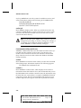
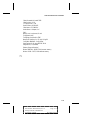
Installation Guide
APA-460 SlimSCSI
PCMCIA-to-SCSI Host Adapter
A
AAAAAAAAAAAAAAAAAAAAAAAAAAAAAAAAAAAAAAAAAAAAAAAAAAAAAAAAAAAAA
AA
A
APA-460 Installation Guide
A
AA
A
A
Stock Number: TR510070-00, Rev. B
Page: Front Cover AA
A
A
AA
A
Print Spec Number: TR490120-00
A
AA
A
A
Current Date: 3/25/94
ECN Date: 4/5/94 AA
A
AAAA
A
AAAAAAAA
A
AAAAAAAA
AAAAAAAA
AAAAAAAA
AAAAAAAA
AAAAAAAA
AAAAAAAA
AAAAAAAA
AAAAAAAA
AAAAAAAA
AAAAAAAA
AAAAAAAA
AAAAAAAA
AAAAAAAA
AAAAAA
Adaptec, Inc.
691 South Milpitas Boulevard
Milpitas, CA 95035
Copyright © 1993, 1994, Adaptec, Inc.
All rights reserved. Adaptec and the
Adaptec logo are registered trademarks
of Adaptec, Inc.
Printed in Singapore
STOCK NO.: TR510070-00, Rev. B CV 4/94
A
AAAAAAAAAAAAAAAAAAAAAAAAAAAAAAAAAAAAAAAAAAAAAAAAAAAAAAAAAAAAA
AA
A
APA-460 Installation Guide
A
AA
A
A
Stock Number: TR510070-00, Rev. B
Page: Back Cover AA
A
A
AA
A
Print Spec Number: TR490120-00
A
AA
A
A
Current Date: 3/25/94
ECN Date: 4/5/94 AA
A
AAAA
A
AAAAAAAA
A
AAAAAAAA
AAAAAAAA
AAAAAAAA
AAAAAAAA
AAAAAAAA
AAAAAAAA
AAAAAAAA
AAAAAAAA
AAAAAAAA
AAAAAAAA
AAAAAAAA
AAAAAAAA
AAAAAAAA
AAAAAA
APA-460 SlimSCSI
PCMCIA-to-SCSI Host Adapter
Installation Guide
R
A
AAAAAAAAAAAAAAAAAAAAAAAAAAAAAAAAAAAAAAAAAAAAAAAAAAAAAAAAAAAAA
AA
A
APA-460 Installation Guide
A
AA
A
A
Stock Number: TR510070-00, Rev. B
Page: i AA
A
A
AA
A
Print Spec Number: TR490120-00
A
AA
A
A
Current Date: 3/25/94
ECN Date: 4/5/94 AA
A
AAAA
A
AAAAAAAA
A
AAAAAAAA
AAAAAAAA
AAAAAAAA
AAAAAAAA
AAAAAAAA
AAAAAAAA
AAAAAAAA
AAAAAAAA
AAAAAAAA
AAAAAAAA
AAAAAAAA
AAAAAAAA
AAAAAAAA
AAAAAA
Copyright
Copyright © 1993, 1994 Adaptec, Inc. All rights reserved. No part of this publication
may be reproduced, stored in a retrieval system, or transmitted in any form or by any
means, electronic, mechanical, photocopying, recording or otherwise, without the
prior written consent of Adaptec, Inc., 691 South Milpitas Blvd., Milpitas, CA 95035.
Trademarks
Adaptec, the Adaptec logo, and SlimSCSI are registered trademarks and APA is a
trademark of Adaptec, Inc.
Bernoulli is a registered trademark of Iomega Corporation.
Cirrus is a registered trademark of Cirrus Logic, Inc.
Databook is a registered trademark of WordPerfect Corporation.
Floptical is a registered trademark of Insite Peripherals.
HP and ScanJet are registered trademarks of Hewlett-Packard Company.
IBM and OS/2 are registered trademarks of International Business Machines
Corporation.
Intel is a registered trademark of Intel Corporation.
Kodak is a registered trademark and Photo CD is a trademark of Eastman Kodak
Company.
Magic Lantern is a trademark of Incat Systems srl.
Microsoft and MS-DOS are registered trademarks of Microsoft Corporation.
Motorola is a registered trademark of Motorola, Inc.
Music Box, SCSIworks!, and Tape Mate are registered trademarks and Trantor and the
Trantor logo are trademarks of Trantor Systems Limited, an Adaptec company.
Novell and NetWare are registered trademarks of Novell, Inc.
SyQuest is a registered trademark of SyQuest Technology, Inc.
SystemSoft is a registered trademark and CardSoft is a trademark of SystemSoft
Corporation.
Changes
The material in this guide is for information only and is subject to change without
notice. While reasonable efforts have been made in the preparation of this guide to
assure its accuracy, Adaptec, Inc. assumes no liability resulting from errors or omissions in this guide, or from the use of the information contained herein.
Adaptec reserves the right to make changes in the product design without reservation
and without notification to its users.
Adaptec Technical Support
APA-460 host adapters have been specifically developed for easy installation and use.
We believe that our guides and the on-screen instructions and help are complete and
clear enough to meet your needs. If you need further help, please contact us.
ii
A
AAAAAAAAAAAAAAAAAAAAAAAAAAAAAAAAAAAAAAAAAAAAAAAAAAAAAAAAAAAAA
AA
A
APA-460 Installation Guide
A
AA
A
A
Stock Number: TR510070-00, Rev. B
Page: ii AA
A
A
AA
A
Print Spec Number: TR490120-00
A
AA
A
A
Current Date: 3/25/94
ECN Date: 4/5/94 AA
A
AAAA
A
AAAAAAAA
A
AAAAAAAA
AAAAAAAA
AAAAAAAA
AAAAAAAA
AAAAAAAA
AAAAAAAA
AAAAAAAA
AAAAAAAA
AAAAAAAA
AAAAAAAA
AAAAAAAA
AAAAAAAA
AAAAAAAA
AAAAAA
●
The Adaptec Electronic Bulletin Board Service (BBS) provides information on
software upgrades, new releases, technical advice, and other topics. The BBS is
available 24 hours a day at 408-945-7727; 1200/2400/9600/14400 baud, 8 data bits,
1 stop bit, no parity.
●
To contact the Adaptec Technical Support Hot Line, call 800-959-SCSI (7274) or
408-945-2550; M–Th: 6:00 a.m. to 5:00 p.m., F: 6:00 a.m. to 3:00 p.m., Pacific Time.
Interactive FAX Service
The Adaptec Interactive FAX Service provides the latest on-line information about
Adaptec products and services. The Adaptec Interactive FAX Service is available
23 hours a day, seven days a week, at 408-957-7150.
Ordering Software and Cables
To order Adaptec software and SCSI cables, call 800-442-SCSI (7274), M–F: 5:00 a.m. to
6:00 p.m., Pacific Time.
Literature Hotline
To request additional documentation for Adaptec products, call 800-934-2766,
M–F: 5:00 a.m. to 6:00 p.m., Pacific Time.
FCC Compliance Statement
This equipment has been tested and found to comply with the limits for a Class B digital device,
pursuant to Part 15 of the FCC rules. These limits are designed to provide reasonable protection
against harmful interference in residential installations. This equipment generates, uses, and can
radiate radio frequency energy, and if not installed and used in accordance with the instructions,
may cause harmful interference to radio communications. However, there is no guarantee that
interference will not occur in a particular installation.
If this equipment does cause interference to radio or television equipment reception, which can be
determined by turning the equipment off and on, the user is encouraged to try to correct the interference by one or more of the following measures:
• Reorient or relocate the receiving antenna
• Move the equipment away from the receiver
• Plug the equipment into an outlet on a circuit different from that to which the receiver is
powered
• If necessary, the user should consult the dealer or an experienced radio/television technician
for additional suggestions
CAUTION: Only equipment certified to comply with Class B (computer input/output devices,
terminals, printers, etc.) should be attached to this equipment, and must have shielded interface
cables.
Finally, any changes or modifications to the equipment by the user not expressly approved by the
grantee or manufacturer could void the user ’s authority to operate such equipment.
Each APA-460 host adapter is equipped with an FCC compliance label which shows only the FCC
identification number. The full text of the associated label follows:
This device complies with part 15 of the FCC rules. Operation is subject to the following
two conditions: (1) this device may not cause harmful interference and (2) this device
must accept any interference received, including interference that may cause undesired
operation.
iii
A
AAAAAAAAAAAAAAAAAAAAAAAAAAAAAAAAAAAAAAAAAAAAAAAAAAAAAAAAAAAAA
AA
A
APA-460 Installation Guide
A
AA
A
A
Stock Number: TR510070-00, Rev. B
Page: iii AA
A
A
AA
A
Print Spec Number: TR490120-00
A
AA
A
A
Current Date: 3/25/94
ECN Date: 4/5/94 AA
A
AAAA
A
AAAAAAAA
A
AAAAAAAA
AAAAAAAA
AAAAAAAA
AAAAAAAA
AAAAAAAA
AAAAAAAA
AAAAAAAA
AAAAAAAA
AAAAAAAA
AAAAAAAA
AAAAAAAA
AAAAAAAA
AAAAAAAA
AAAAAA
A
AAAAAAAAAAAAAAAAAAAAAAAAAAAAAAAAAAAAAAAAAAAAAAAAAAAAAAAAAAAAA
AA
A
APA-460 Installation Guide
A
AA
A
A
Stock Number: TR510070-00, Rev. B
Page: iv AA
A
A
AA
A
Print Spec Number: TR490120-00
A
AA
A
A
Current Date: 3/25/94
ECN Date: 4/5/94 AA
A
AAAA
A
AAAAAAAA
A
AAAAAAAA
AAAAAAAA
AAAAAAAA
AAAAAAAA
AAAAAAAA
AAAAAAAA
AAAAAAAA
AAAAAAAA
AAAAAAAA
AAAAAAAA
AAAAAAAA
AAAAAAAA
AAAAAAAA
AAAAAA
▼ ▼ ▼ ▼
Table of Contents
Preface
Inside This Guide ix
Conventions x
Advisories xi
1 Introduction
About This Chapter 1-1
SlimSCSI Features and Benefits 1-3
Hardware Requirements 1-4
Checklist 1-4
Installation and Operation Overview 1-5
2 SlimSCSI Hardware Installation
About This Chapter 2-1
Hardware Installation 2-3
SCSI Connector Pinouts 2-7
3 SlimSCSI Adapter Operation
About This Chapter 3-1
Notes on SCSIworks! Software Installation 3-3
Operation 3-3
Common Error Messages and Remedies 3-4
A Card and Socket Services Installation
About This Appendix A-1
Introduction A-3
Installation A-3
Modem and Memory Card Support within
Windows 3.1 A-6
Installation Notes A-7
Drivers and Utilities A-8
v
A
AAAAAAAAAAAAAAAAAAAAAAAAAAAAAAAAAAAAAAAAAAAAAAAAAAAAAAAAAAAAA
AA
A
APA-460 Installation Guide
A
AA
A
A
Stock Number: TR510070-00, Rev. B
Page: v AA
A
A
AA
A
Print Spec Number: TR490120-00
A
AA
A
A
Current Date: 3/25/94
ECN Date: 4/5/94 AA
A
AAAA
A
AAAAAAAA
A
AAAAAAAA
AAAAAAAA
AAAAAAAA
AAAAAAAA
AAAAAAAA
AAAAAAAA
AAAAAAAA
AAAAAAAA
AAAAAAAA
AAAAAAAA
AAAAAAAA
AAAAAAAA
AAAAAAAA
AAAAAA
APA-460 Installation Guide
B CardSoft Software Configuration
About This Appendix B-1
Configuration Notes B-3
Configuration Utility B-3
Device Line Parameters B-3
Running the Configuration Utility B-4
Accessing Menu Items B-5
Exiting the Configuration Utility B-5
Editing PC Card Configuration Parameters B-5
Saving PC Card Configuration Parameters B-10
Allocating System Resources for Card
Services B-10
Changing the Configuration Utility Display
Mode B-14
vi
A
AAAAAAAAAAAAAAAAAAAAAAAAAAAAAAAAAAAAAAAAAAAAAAAAAAAAAAAAAAAAA
AA
A
APA-460 Installation Guide
A
AA
A
A
Stock Number: TR510070-00, Rev. B
Page: vi AA
A
A
AA
A
Print Spec Number: TR490120-00
A
AA
A
A
Current Date: 3/25/94
ECN Date: 4/5/94 AA
A
AAAA
A
AAAAAAAA
A
AAAAAAAA
AAAAAAAA
AAAAAAAA
AAAAAAAA
AAAAAAAA
AAAAAAAA
AAAAAAAA
AAAAAAAA
AAAAAAAA
AAAAAAAA
AAAAAAAA
AAAAAAAA
AAAAAAAA
AAAAAA
▼ ▼ ▼ ▼
List of Figures
Figure
1-1
APA-460 SlimSCSI Adapter 1-3
2-1
2-2
Installing the SlimSCSI Adapter 2-4
2-3
2-4
Connecting Multiple External SCSI Devices 2-6
B-1
B-2
B-3
B-4
B-5
B-6
B-7
B-8
Configuration Utility Screen (Option 1) B-4
Connecting the SlimSCSI Male SCSI Connector to the
SCSI Device 2-5
Female SCSI Device Connector 2-7
Edit Configuration Menu B-6
Card Insertion Parameters Menu B-7
Modem Card Configuration Menu B-8
Network Card Information Menu B-9
ATA Parameters Menu B-10
Resource Allocation Menu B-11
Add A New Resource Screen B-12
vii
A
AAAAAAAAAAAAAAAAAAAAAAAAAAAAAAAAAAAAAAAAAAAAAAAAAAAAAAAAAAAAA
AA
A
APA-460 Installation Guide
A
AA
A
A
Stock Number: TR510070-00, Rev. B
Page: vii AA
A
A
AA
A
Print Spec Number: TR490120-00
A
AA
A
A
Current Date: 3/25/94
ECN Date: 4/5/94 AA
A
AAAA
A
AAAAAAAA
A
AAAAAAAA
AAAAAAAA
AAAAAAAA
AAAAAAAA
AAAAAAAA
AAAAAAAA
AAAAAAAA
AAAAAAAA
AAAAAAAA
AAAAAAAA
AAAAAAAA
AAAAAAAA
AAAAAAAA
AAAAAA
A
AAAAAAAAAAAAAAAAAAAAAAAAAAAAAAAAAAAAAAAAAAAAAAAAAAAAAAAAAAAAA
AA
A
APA-460 Installation Guide
A
AA
A
A
Stock Number: TR510070-00, Rev. B
Page: viii AA
A
A
AA
A
Print Spec Number: TR490120-00
A
AA
A
A
Current Date: 3/25/94
ECN Date: 4/5/94 AA
A
AAAA
A
AAAAAAAA
A
AAAAAAAA
AAAAAAAA
AAAAAAAA
AAAAAAAA
AAAAAAAA
AAAAAAAA
AAAAAAAA
AAAAAAAA
AAAAAAAA
AAAAAAAA
AAAAAAAA
AAAAAAAA
AAAAAAAA
AAAAAA
▼ ▼ ▼ ▼
Preface
Inside This Guide
This guide describes installation and operation of the
Adaptec® APA™-460 SlimSCSI™ PCMCIA-to-SCSI
adapter (hereafter referred to as the SlimSCSI
adapter) for PCMCIA type II-compatible computer
systems. The SlimSCSI also works with PCMCIA
type III slots or Toshiba type IV slots. This guide also
contains installation and operation of CardSoft™ Card
and Socket Services software.
Here are brief descriptions of each chapter.
Chapter 1
Introduction
explains the features and benefits of the APA-460
SlimSCSI host adapter.
Chapter 2
SlimSCSI Hardware Installation
explains how to install the APA-460 SlimSCSI into a
system and connect SCSI devices.
Chapter 3
SlimSCSI Adapter Operation
explains how to install SCSIworks!™ software and
operate the SlimSCSI host adapter.
Appendix A
Card and Socket Services Installation
explains features and installation procedures for
CardSoft Card and Socket Services software.
Appendix B
CardSoft Software Configuration
explains how to configure and use Card and Socket
Services software.
ix
A
AAAAAAAAAAAAAAAAAAAAAAAAAAAAAAAAAAAAAAAAAAAAAAAAAAAAAAAAAAAAA
AA
A
APA-460 Installation Guide
A
AA
A
A
Stock Number: TR510070-00, Rev. B
Page: ix AA
A
A
AA
A
Print Spec Number: TR490120-00
A
AA
A
A
Current Date: 3/25/94
ECN Date: 4/5/94 AA
A
AAAA
A
AAAAAAAA
A
AAAAAAAA
AAAAAAAA
AAAAAAAA
AAAAAAAA
AAAAAAAA
AAAAAAAA
AAAAAAAA
AAAAAAAA
AAAAAAAA
AAAAAAAA
AAAAAAAA
AAAAAAAA
AAAAAAAA
AAAAAA
APA-460 Installation Guide
Conventions
The following typographic conventions are used in
this guide.
bold
Used for keystrokes (… press the Enter key …).
Helvetica
Used for operator entry that must be typed exactly as
shown (… device=c:aspi2dos.sys …) and for messages on the screen (… Enter Password …).
Helvetica Italics
Used as a place holder for text you must determine
and type in (… enter nn for number …). Also used for
program and file names that appear in body text
(… the autoexec.bat file …).
Italics
Used for emphasis (… is only supported …) and for
document references (… refer to Chapter 1,
Introduction…).
Hexadecimal Numbers
Are followed by an ‘h’, e.g., 330h.
End Mark
The ❐ symbol marks the end of a chapter or other
section.
x
A
AAAAAAAAAAAAAAAAAAAAAAAAAAAAAAAAAAAAAAAAAAAAAAAAAAAAAAAAAAAAA
AA
A
APA-460 Installation Guide
A
AA
A
A
Stock Number: TR510070-00, Rev. B
Page: x AA
A
A
AA
A
Print Spec Number: TR490120-00
A
AA
A
A
Current Date: 3/25/94
ECN Date: 4/5/94 AA
A
AAAA
A
AAAAAAAA
A
AAAAAAAA
AAAAAAAA
AAAAAAAA
AAAAAAAA
AAAAAAAA
AAAAAAAA
AAAAAAAA
AAAAAAAA
AAAAAAAA
AAAAAAAA
AAAAAAAA
AAAAAAAA
AAAAAAAA
AAAAAA
Preface
Advisories
Advisories are quick notes that stress an important
point or warn of a potential hazard to your system or
your data. This guide uses one kind of advisory:
Note: Text set off in this way presents reminders, tips, or suggestions that may make it easier for you to install, configure, and use your
host adapter.
Use caution when handling any electrical equipment.
Advisories in this guide can only cover the procedures contained here, and not all situations may have
been addressed. Adaptec does not claim to have
included every condition or situation that might
require a Caution or Warning. You must refer to the
documentation for your computer peripheral equipment when you are installing equipment or changing
its configuration.
❒
xi
A
AAAAAAAAAAAAAAAAAAAAAAAAAAAAAAAAAAAAAAAAAAAAAAAAAAAAAAAAAAAAA
AA
A
APA-460 Installation Guide
A
AA
A
A
Stock Number: TR510070-00, Rev. B
Page: xi AA
A
A
AA
A
Print Spec Number: TR490120-00
A
AA
A
A
Current Date: 3/25/94
ECN Date: 4/5/94 AA
A
AAAA
A
AAAAAAAA
A
AAAAAAAA
AAAAAAAA
AAAAAAAA
AAAAAAAA
AAAAAAAA
AAAAAAAA
AAAAAAAA
AAAAAAAA
AAAAAAAA
AAAAAAAA
AAAAAAAA
AAAAAAAA
AAAAAAAA
AAAAAA
A
AAAAAAAAAAAAAAAAAAAAAAAAAAAAAAAAAAAAAAAAAAAAAAAAAAAAAAAAAAAAA
AA
A
APA-460 Installation Guide
A
AA
A
A
Stock Number: TR510070-00, Rev. B
Page: xii AA
A
A
AA
A
Print Spec Number: TR490120-00
A
AA
A
A
Current Date: 3/25/94
ECN Date: 4/5/94 AA
A
AAAA
A
AAAAAAAA
A
AAAAAAAA
AAAAAAAA
AAAAAAAA
AAAAAAAA
AAAAAAAA
AAAAAAAA
AAAAAAAA
AAAAAAAA
AAAAAAAA
AAAAAAAA
AAAAAAAA
AAAAAAAA
AAAAAAAA
AAAAAA
▼ ▼ ▼ ▼
1
Introduction
About This Chapter
Read this chapter to find out about
■
SlimSCSI features and benefits
■
System requirements
1-1
A
AAAAAAAAAAAAAAAAAAAAAAAAAAAAAAAAAAAAAAAAAAAAAAAAAAAAAAAAAAAAA
AA
A
APA-460 Installation Guide
A
AA
A
A
Stock Number: TR510070-00, Rev. B
Page: 1-1 AA
A
A
AA
A
Print Spec Number: TR490120-00
A
AA
A
A
Current Date: 3/25/94
ECN Date: 4/5/94 AA
A
AAAA
A
AAAAAAAA
A
AAAAAAAA
AAAAAAAA
AAAAAAAA
AAAAAAAA
AAAAAAAA
AAAAAAAA
AAAAAAAA
AAAAAAAA
AAAAAAAA
AAAAAAAA
AAAAAAAA
AAAAAAAA
AAAAAAAA
AAAAAA
A
AAAAAAAAAAAAAAAAAAAAAAAAAAAAAAAAAAAAAAAAAAAAAAAAAAAAAAAAAAAAA
AA
A
APA-460 Installation Guide
A
AA
A
A
Stock Number: TR510070-00, Rev. B
Page: 1-2 AA
A
A
AA
A
Print Spec Number: TR490120-00
A
AA
A
A
Current Date: 3/25/94
ECN Date: 4/5/94 AA
A
AAAA
A
AAAAAAAA
A
AAAAAAAA
AAAAAAAA
AAAAAAAA
AAAAAAAA
AAAAAAAA
AAAAAAAA
AAAAAAAA
AAAAAAAA
AAAAAAAA
AAAAAAAA
AAAAAAAA
AAAAAAAA
AAAAAAAA
AAAAAA
Introduction
▼ ▼ ▼ ▼
1
SlimSCSI Features and Benefits
Your SlimSCSI adapter has been designed to provide simple, flexible
control of most SCSI hard disks, removable-cartridge disks,
Floptical® drives, magneto-optical drives, SCSI-interfaced
Bernoulli® and SyQuest® drives, SCSI floppy and tape drives,
CD-ROMs (including single and multisession Kodak® Photo CD™),
and HP ® ScanJet® II scanners. Figure 1-1 illustrates the SlimSCSI
adapter.
Figure 1-1. APA-460 SlimSCSI Adapter
Some of the important features include the following:
■
High-speed operation
■
Simple installation, just plug the reversible 3-foot cable into
your SlimSCSI adapter and connect it to your SCSI device(s)
■
Standard SCSI interface connector, permitting the use of almost
any SCSI-compatible device
■
Small size and light weight for easy portability
1-3
A
AAAAAAAAAAAAAAAAAAAAAAAAAAAAAAAAAAAAAAAAAAAAAAAAAAAAAAAAAAAAA
AA
A
APA-460 Installation Guide
A
AA
A
A
Stock Number: TR510070-00, Rev. B
Page: 1-3 AA
A
A
AA
A
Print Spec Number: TR490120-00
A
AA
A
A
Current Date: 3/25/94
ECN Date: 4/5/94 AA
A
AAAA
A
AAAAAAAA
A
AAAAAAAA
AAAAAAAA
AAAAAAAA
AAAAAAAA
AAAAAAAA
AAAAAAAA
AAAAAAAA
AAAAAAAA
AAAAAAAA
AAAAAAAA
AAAAAAAA
AAAAAAAA
AAAAAAAA
AAAAAA
APA-460 Installation Guide
■
■
Easy-to-use SystemSoft® CardSoft Card and Socket Services
software to enable plug and play features in your PCMCIA
system
Easy-to-use SCSIworks! software with SlimSCSI support for
most SCSI devices in the DOS and Windows operating systems; also includes Magic Lantern™ photo CD viewer,
Music Box® CD-ROM audio control software, and
Tape Mate® II SCSI tape backup software
Note: Though SCSIworks! software includes drivers
for OS/2® and NetWare®, these operating systems do
not yet provide support for PCMCIA-to-SCSI adapters, such as the SlimSCSI adapter.
Hardware Requirements
The SlimSCSI adapter is designed to be as universally usable as
possible, but there are four important hardware compatibility
requirements:
■
The SCSI bus properly terminated as per ANSI SCSI
specifications
■
A computer with a PCMCIA type II or type III slot, or Toshiba
type IV slot
■
The host PCMCIA controller supported by CardSoft software
■
A 100% IBM®-compatible BIOS (operation with an incompatible BIOS may be possible but is not guaranteed.)
Checklist
You should have received the following items in your SlimSCSI
adapter package:
■
SlimSCSI host adapter and cable
■
3.5-inch, 720-KByte low-density CardSoft software distribution
diskette
■
3.5-inch, 1.44-MByte high-density SCSIworks! software distribution diskette(s)
1-4
A
AAAAAAAAAAAAAAAAAAAAAAAAAAAAAAAAAAAAAAAAAAAAAAAAAAAAAAAAAAAAA
AA
A
APA-460 Installation Guide
A
AA
A
A
Stock Number: TR510070-00, Rev. B
Page: 1-4 AA
A
A
AA
A
Print Spec Number: TR490120-00
A
AA
A
A
Current Date: 3/25/94
ECN Date: 4/5/94 AA
A
AAAA
A
AAAAAAAA
A
AAAAAAAA
AAAAAAAA
AAAAAAAA
AAAAAAAA
AAAAAAAA
AAAAAAAA
AAAAAAAA
AAAAAAAA
AAAAAAAA
AAAAAAAA
AAAAAAAA
AAAAAAAA
AAAAAAAA
AAAAAA
Introduction
■
APA-460 SlimSCSI Installation Guide (this document)
■
SCSIworks! Software User Guide
■
Product Registration card
■
Microsoft® MSCDEX Software Registration card
If anything is missing, please contact your dealer immediately.
Installation and Operation Overview
Follow these steps, in this order, to install and use the SlimSCSI
adapter:
1
Install Card and Socket Services software if your system did
not come with this software already installed. (This software
enables PCMCIA slot plug and play features.) Adaptec has
supplied CardSoft Card and Socket Services software with
your SlimSCSI adapter; see Appendix A, Card and Socket Services Installation, for complete installation instructions.
2
Install the SlimSCSI adapter into your PCMCIA-compatible
computer. See Chapter 2, SlimSCSI Hardware Installation, for
details.
3
Install SCSIworks! software and operate the SlimSCSI adapter.
See Chapter 3, SlimSCSI Adapter Operation, for details; this
chapter also includes common error messages and their
remedies.
❒
1-5
A
AAAAAAAAAAAAAAAAAAAAAAAAAAAAAAAAAAAAAAAAAAAAAAAAAAAAAAAAAAAAA
AA
A
APA-460 Installation Guide
A
AA
A
A
Stock Number: TR510070-00, Rev. B
Page: 1-5 AA
A
A
AA
A
Print Spec Number: TR490120-00
A
AA
A
A
Current Date: 3/25/94
ECN Date: 4/5/94 AA
A
AAAA
A
AAAAAAAA
A
AAAAAAAA
AAAAAAAA
AAAAAAAA
AAAAAAAA
AAAAAAAA
AAAAAAAA
AAAAAAAA
AAAAAAAA
AAAAAAAA
AAAAAAAA
AAAAAAAA
AAAAAAAA
AAAAAAAA
AAAAAA
A
AAAAAAAAAAAAAAAAAAAAAAAAAAAAAAAAAAAAAAAAAAAAAAAAAAAAAAAAAAAAA
AA
A
APA-460 Installation Guide
A
AA
A
A
Stock Number: TR510070-00, Rev. B
Page: 1-6 AA
A
A
AA
A
Print Spec Number: TR490120-00
A
AA
A
A
Current Date: 3/25/94
ECN Date: 4/5/94 AA
A
AAAA
A
AAAAAAAA
A
AAAAAAAA
AAAAAAAA
AAAAAAAA
AAAAAAAA
AAAAAAAA
AAAAAAAA
AAAAAAAA
AAAAAAAA
AAAAAAAA
AAAAAAAA
AAAAAAAA
AAAAAAAA
AAAAAAAA
AAAAAA
▼ ▼ ▼ ▼
2
SlimSCSI
Hardware
Installation
About This Chapter
Read this chapter to find out about
■
Hardware installation for the SlimSCSI
■
SCSI connector pinouts
2-1
A
AAAAAAAAAAAAAAAAAAAAAAAAAAAAAAAAAAAAAAAAAAAAAAAAAAAAAAAAAAAAA
AA
A
APA-460 Installation Guide
A
AA
A
A
Stock Number: TR510070-00, Rev. B
Page: 2-1 AA
A
A
AA
A
Print Spec Number: TR490120-00
A
AA
A
A
Current Date: 3/25/94
ECN Date: 4/5/94 AA
A
AAAA
A
AAAAAAAA
A
AAAAAAAA
AAAAAAAA
AAAAAAAA
AAAAAAAA
AAAAAAAA
AAAAAAAA
AAAAAAAA
AAAAAAAA
AAAAAAAA
AAAAAAAA
AAAAAAAA
AAAAAAAA
AAAAAAAA
AAAAAA
A
AAAAAAAAAAAAAAAAAAAAAAAAAAAAAAAAAAAAAAAAAAAAAAAAAAAAAAAAAAAAA
AA
A
APA-460 Installation Guide
A
AA
A
A
Stock Number: TR510070-00, Rev. B
Page: 2-2 AA
A
A
AA
A
Print Spec Number: TR490120-00
A
AA
A
A
Current Date: 3/25/94
ECN Date: 4/5/94 AA
A
AAAA
A
AAAAAAAA
A
AAAAAAAA
AAAAAAAA
AAAAAAAA
AAAAAAAA
AAAAAAAA
AAAAAAAA
AAAAAAAA
AAAAAAAA
AAAAAAAA
AAAAAAAA
AAAAAAAA
AAAAAAAA
AAAAAAAA
AAAAAA
SlimSCSI Hardware Installation
▼ ▼ ▼ ▼
2
Hardware Installation
Hardware installation involves plugging the SlimSCSI adapter into
a PCMCIA type II or type III slot (or Toshiba type IV slot) and connecting it to the applicable SCSI device(s), as described in the following steps. Please see Common Error Messages and Remedies on page
3-4 for troubleshooting assistance with possible problems which
may develop.
Note: If your system did not come with Card and Socket
Services software installed, you must install CardSoft Card
and Socket Services software provided by Adaptec now. If
you do not install Card and Socket Services software your
system will not recognize the PCMCIA slot(s) or the adapters and devices connected. See Appendix A, Card and Socket
Services Installation.
2-3
A
AAAAAAAAAAAAAAAAAAAAAAAAAAAAAAAAAAAAAAAAAAAAAAAAAAAAAAAAAAAAA
AA
A
APA-460 Installation Guide
A
AA
A
A
Stock Number: TR510070-00, Rev. B
Page: 2-3 AA
A
A
AA
A
Print Spec Number: TR490120-00
A
AA
A
A
Current Date: 3/25/94
ECN Date: 4/5/94 AA
A
AAAA
A
AAAAAAAA
A
AAAAAAAA
AAAAAAAA
AAAAAAAA
AAAAAAAA
AAAAAAAA
AAAAAAAA
AAAAAAAA
AAAAAAAA
AAAAAAAA
AAAAAAAA
AAAAAAAA
AAAAAAAA
AAAAAAAA
AAAAAA
APA-460 Installation Guide
1
Connect your SlimSCSI adapter to its proprietary cable connector; the reversible connector allows it to be connected either
way (see Figure 2-1).
Figure 2-1. Installing the SlimSCSI Adapter
2
Insert the SlimSCSI adapter into the PCMCIA type II, type III,
or Toshiba type IV slot (see Figure 2-1).
3
Connect the first external SCSI device to the SCSI connector on
the SlimSCSI adapter (see Figure 2-2).
External SCSI devices use a 50-pin shielded cable with an
external connector. External cable connectors are keyed and
2-4
A
AAAAAAAAAAAAAAAAAAAAAAAAAAAAAAAAAAAAAAAAAAAAAAAAAAAAAAAAAAAAA
AA
A
APA-460 Installation Guide
A
AA
A
A
Stock Number: TR510070-00, Rev. B
Page: 2-4 AA
A
A
AA
A
Print Spec Number: TR490120-00
A
AA
A
A
Current Date: 3/25/94
ECN Date: 4/5/94 AA
A
AAAA
A
AAAAAAAA
A
AAAAAAAA
AAAAAAAA
AAAAAAAA
AAAAAAAA
AAAAAAAA
AAAAAAAA
AAAAAAAA
AAAAAAAA
AAAAAAAA
AAAAAAAA
AAAAAAAA
AAAAAAAA
AAAAAAAA
AAAAAA
SlimSCSI Hardware Installation
can only be plugged-in one way; pin-1 orientation is
automatic.
SCSI Device
Terminator
SlimSCSI Adapter
(male) SCSI Connector
Figure 2-2. Connecting the SlimSCSI Male SCSI Connector to the SCSI Device
4
To connect other SCSI devices (up to seven total), obtain additional external cables and daisy-chain each device to the previous device until all SCSI devices have been connected.
Daisy-chaining means that a simple two-ended cable runs
from the host adapter to the connector on the first external
SCSI device; a second connector on the back of the external
SCSI device allows another cable to connect it with the second
SCSI device in the chain. Up to seven external SCSI devices can
be included in the daisy-chain (as shown on the next page).
2-5
A
AAAAAAAAAAAAAAAAAAAAAAAAAAAAAAAAAAAAAAAAAAAAAAAAAAAAAAAAAAAAA
AA
A
APA-460 Installation Guide
A
AA
A
A
Stock Number: TR510070-00, Rev. B
Page: 2-5 AA
A
A
AA
A
Print Spec Number: TR490120-00
A
AA
A
A
Current Date: 3/25/94
ECN Date: 4/5/94 AA
A
AAAA
A
AAAAAAAA
A
AAAAAAAA
AAAAAAAA
AAAAAAAA
AAAAAAAA
AAAAAAAA
AAAAAAAA
AAAAAAAA
AAAAAAAA
AAAAAAAA
AAAAAAAA
AAAAAAAA
AAAAAAAA
AAAAAAAA
AAAAAA
APA-460 Installation Guide
Figure 2-3 shows three SCSI devices in a daisy-chain.
SCSI Devices
Terminator
Figure 2-3. Connecting Multiple External SCSI Devices
5
Terminate the last (or only) SCSI device connected to the
SlimSCSI adapter, per manufacturer’s specifications. Most
SCSI devices use a jumper or switch near their SCSI connector(s) to control termination. On some SCSI devices, you must
physically remove or install terminator resistor modules. An
external terminator is installed in Figures 2-2 and 2-3. See your
device documentation for termination information.
Note: The SlimSCSI adapter itself is actively terminated by default and cannot be changed, since both
ends of the SCSI bus must be terminated.
6
If the SCSI device(s) connected to the SlimSCSI adapter
requires term power output, this output must be provided by
the device itself. The SlimSCSI adapter does not provide term
power. See your SCSI device documentation for more
information.
7
If you connect more than one SCSI device to your SlimSCSI
adapter simultaneously, make sure that each device’s SCSI ID
(device number between 0 and 6) is different. ID 7 is reserved
for the SlimSCSI adapter. Different IDs are essential to prevent
conflicts when the SlimSCSI adapter communicates with the
devices.
2-6
A
AAAAAAAAAAAAAAAAAAAAAAAAAAAAAAAAAAAAAAAAAAAAAAAAAAAAAAAAAAAAA
AA
A
APA-460 Installation Guide
A
AA
A
A
Stock Number: TR510070-00, Rev. B
Page: 2-6 AA
A
A
AA
A
Print Spec Number: TR490120-00
A
AA
A
A
Current Date: 3/25/94
ECN Date: 4/5/94 AA
A
AAAA
A
AAAAAAAA
A
AAAAAAAA
AAAAAAAA
AAAAAAAA
AAAAAAAA
AAAAAAAA
AAAAAAAA
AAAAAAAA
AAAAAAAA
AAAAAAAA
AAAAAAAA
AAAAAAAA
AAAAAAAA
AAAAAAAA
AAAAAA
SlimSCSI Hardware Installation
The SCSI ID on most SCSI devices is set with jumpers or
switches. Refer to the SCSI device documentation for information on changing the SCSI ID.
SCSI Connector Pinouts
This section documents the SCSI interface connectors on the
SlimSCSI adapter cable as well as the typical mating connectors
found on SCSI devices. The connector on the SlimSCSI adapter and
the connector that attaches the SlimSCSI cable to the adapter are
proprietary. See Figure 2-1.
A typical single-ended, shielded female SCSI device 50-pin connector is shown in Figure 2-4. This connector is most often used with
external SCSI devices; the SCSI (male) connector on the SlimSCSI
adapter connects to it.
Figure 2-4. Female SCSI Device Connector
Table 1 lists the pin assignments for each connector type. Definitions
of the various signals may be found in any SCSI design reference
book. The SCSI interface is fully defined in ANSI X3.131-1986, which
is available from Global Engineering Documents, 2805 McGaw Ave.,
Irvine, CA 92713-9539 USA, telephone (714) 261-1455.
2-7
A
AAAAAAAAAAAAAAAAAAAAAAAAAAAAAAAAAAAAAAAAAAAAAAAAAAAAAAAAAAAAA
AA
A
APA-460 Installation Guide
A
AA
A
A
Stock Number: TR510070-00, Rev. B
Page: 2-7 AA
A
A
AA
A
Print Spec Number: TR490120-00
A
AA
A
A
Current Date: 3/25/94
ECN Date: 4/5/94 AA
A
AAAA
A
AAAAAAAA
A
AAAAAAAA
AAAAAAAA
AAAAAAAA
AAAAAAAA
AAAAAAAA
AAAAAAAA
AAAAAAAA
AAAAAAAA
AAAAAAAA
AAAAAAAA
AAAAAAAA
AAAAAAAA
AAAAAAAA
AAAAAA
APA-460 Installation Guide
1
Signal Name
Pinout1
Pinout1
Signal Name
Ground
1
26
-DB(0)
Ground
2
27
-DB(1)
Ground
3
28
-DB(2)
Ground
4
29
-DB(3)
Ground
5
30
-DB(4)
Ground
6
31
-DB(5)
Ground
7
32
-DB(6)
Ground
8
33
-DB(7)
Ground
9
34
-DB(P)
Ground
10
35
Ground
Ground
11
36
Ground
Ground
12
37
Ground
Open
13
38
Term Power
Ground
14
39
Ground
Ground
15
40
Ground
Ground
16
41
-ATN
Ground
17
42
Ground
Ground
18
43
-BSY
Ground
19
44
-ACK
Ground
20
45
-RST
Ground
21
46
-MSG
Ground
22
47
-SEL
Ground
23
48
-C/D
Ground
24
49
-REQ
Ground
25
50
-I/O
See Figure 2-2.
❒
2-8
A
AAAAAAAAAAAAAAAAAAAAAAAAAAAAAAAAAAAAAAAAAAAAAAAAAAAAAAAAAAAAA
AA
A
APA-460 Installation Guide
A
AA
A
A
Stock Number: TR510070-00, Rev. B
Page: 2-8 AA
A
A
AA
A
Print Spec Number: TR490120-00
A
AA
A
A
Current Date: 3/25/94
ECN Date: 4/5/94 AA
A
AAAA
A
AAAAAAAA
A
AAAAAAAA
AAAAAAAA
AAAAAAAA
AAAAAAAA
AAAAAAAA
AAAAAAAA
AAAAAAAA
AAAAAAAA
AAAAAAAA
AAAAAAAA
AAAAAAAA
AAAAAAAA
AAAAAAAA
AAAAAA
▼ ▼ ▼ ▼
3
SlimSCSI Adapter
Operation
About This Chapter
Read this chapter to find out about
■
SCSIworks! software installation
■
SlimSCSI operation and use
3-1
A
AAAAAAAAAAAAAAAAAAAAAAAAAAAAAAAAAAAAAAAAAAAAAAAAAAAAAAAAAAAAA
AA
A
APA-460 Installation Guide
A
AA
A
A
Stock Number: TR510070-00, Rev. B
Page: 3-1 AA
A
A
AA
A
Print Spec Number: TR490120-00
A
AA
A
A
Current Date: 3/25/94
ECN Date: 4/5/94 AA
A
AAAA
A
AAAAAAAA
A
AAAAAAAA
AAAAAAAA
AAAAAAAA
AAAAAAAA
AAAAAAAA
AAAAAAAA
AAAAAAAA
AAAAAAAA
AAAAAAAA
AAAAAAAA
AAAAAAAA
AAAAAAAA
AAAAAAAA
AAAAAA
A
AAAAAAAAAAAAAAAAAAAAAAAAAAAAAAAAAAAAAAAAAAAAAAAAAAAAAAAAAAAAA
AA
A
APA-460 Installation Guide
A
AA
A
A
Stock Number: TR510070-00, Rev. B
Page: 3-2 AA
A
A
AA
A
Print Spec Number: TR490120-00
A
AA
A
A
Current Date: 3/25/94
ECN Date: 4/5/94 AA
A
AAAA
A
AAAAAAAA
A
AAAAAAAA
AAAAAAAA
AAAAAAAA
AAAAAAAA
AAAAAAAA
AAAAAAAA
AAAAAAAA
AAAAAAAA
AAAAAAAA
AAAAAAAA
AAAAAAAA
AAAAAAAA
AAAAAAAA
AAAAAA
SlimSCSI Adapter Operation
▼ ▼ ▼ ▼
3
Notes on SCSIworks! Software Installation
Note: Make sure you have installed CardSoft software (if
Card and Socket Services software is not already installed)
before you install SCSIworks! software. See Appendix A,
Card and Socket Services Installation.
Here are a few brief notes on installing SCSIworks! software.
1
Insert SCSIworks! diskette #1 and type a:\install.
2
Load the software as explained in the SCSIworks! Software Users
Guide.
Operation
Make sure the SlimSCSI is attached and the devices are connected to
it and turned ON at bootup, especially for CD-ROM or hard disk
drives. This allows the device drivers to load. However, if you are
using tape drives, it is not necessary to have them installed at
bootup because they work directly through the ASPI manager and
not through a device driver.
Once you have installed SCSIworks! software you may remove and
insert the SlimSCSI adapter at any time except when data is being
transferred via the SCSI bus and SlimSCSI adapter; the device busy
light is ON when data is being transferred.
If the SlimSCSI adapter is not installed when you try to access a
device connected to it, you will receive a message similar to Read
Fault Error Reading Drive X. Reinsert the SlimSCSI adapter into the
PCMCIA socket. It will work correctly if no changes have been
made to the SCSI configuration.
3-3
A
AAAAAAAAAAAAAAAAAAAAAAAAAAAAAAAAAAAAAAAAAAAAAAAAAAAAAAAAAAAAA
AA
A
APA-460 Installation Guide
A
AA
A
A
Stock Number: TR510070-00, Rev. B
Page: 3-3 AA
A
A
AA
A
Print Spec Number: TR490120-00
A
AA
A
A
Current Date: 3/25/94
ECN Date: 4/5/94 AA
A
AAAA
A
AAAAAAAA
A
AAAAAAAA
AAAAAAAA
AAAAAAAA
AAAAAAAA
AAAAAAAA
AAAAAAAA
AAAAAAAA
AAAAAAAA
AAAAAAAA
AAAAAAAA
AAAAAAAA
AAAAAAAA
AAAAAAAA
AAAAAA
APA-460 Installation Guide
Common Error Messages and Remedies
The following are error messages or descriptions of problems you
may encounter. Be sure to read the Troubleshooting and Error Messages
in the SCSIworks! Software User Guide for other software related error
messages and remedies.
I can't boot from a device connected to the SlimSCSI adapter.
Even though you may create a bootable partition with your
SlimSCSI adapter using tformat, you will not be able to boot your
computer with this partition through your SlimSCSI adapter. Your
computer does not expect to boot from a device connected to the
PCMCIA adapter. Therefore, your SlimSCSI adapter device drivers
must be loaded during the boot process from another disk.
“0 Host Adapter Found” message appears during bootup.
Insert the SlimSCSI adapter with devices connected and reboot.
I receive a “Read Fault Error Reading Drive X.”
Reinsert the SlimSCSI adapter, with devices connected, into any
PCMCIA type II slot.
During bootup, the driver recognizes the SlimSCSI adapter and the
SCSI device(s), then stops with a “No SCSI Functions in Use”
message.
The software driver is looking for a different device. For example,
you may have the CD-ROM driver loaded, but you are trying to
work with a hard disk drive, or vice versa. Each software driver recognizes the existence of all SCSI devices attached to the SCSI bus,
but device drivers only work with the device for which they were
written (i.e. hard disk drivers see CD-ROM drives but only communicate with hard disk drives). Install the correct driver or remove an
unwanted driver from your config.sys file using a text editor program or rerun the SCSIworks! Install program.
This message also appears when the device is not formatted correctly. Use an appropriate formatting utility to format the device.
SCSIworks! software contains a formatting utility called tformat;
see your SCSIworks! Software User Guide.
❒
3-4
A
AAAAAAAAAAAAAAAAAAAAAAAAAAAAAAAAAAAAAAAAAAAAAAAAAAAAAAAAAAAAA
AA
A
APA-460 Installation Guide
A
AA
A
A
Stock Number: TR510070-00, Rev. B
Page: 3-4 AA
A
A
AA
A
Print Spec Number: TR490120-00
A
AA
A
A
Current Date: 3/25/94
ECN Date: 4/5/94 AA
A
AAAA
A
AAAAAAAA
A
AAAAAAAA
AAAAAAAA
AAAAAAAA
AAAAAAAA
AAAAAAAA
AAAAAAAA
AAAAAAAA
AAAAAAAA
AAAAAAAA
AAAAAAAA
AAAAAAAA
AAAAAAAA
AAAAAAAA
AAAAAA
▼ ▼ ▼ ▼
A
Card and Socket
Services
Installation
About This Appendix
Read this appendix to find out about
■
Installing Card and Socket Services
software
A-1
A
AAAAAAAAAAAAAAAAAAAAAAAAAAAAAAAAAAAAAAAAAAAAAAAAAAAAAAAAAAAAA
AA
A
APA-460 Installation Guide
A
AA
A
A
Stock Number: TR510070-00, Rev. B
Page: A-1 AA
A
A
AA
A
Print Spec Number: TR490120-00
A
AA
A
A
Current Date: 3/25/94
ECN Date: 4/5/94 AA
A
AAAA
A
AAAAAAAA
A
AAAAAAAA
AAAAAAAA
AAAAAAAA
AAAAAAAA
AAAAAAAA
AAAAAAAA
AAAAAAAA
AAAAAAAA
AAAAAAAA
AAAAAAAA
AAAAAAAA
AAAAAAAA
AAAAAAAA
AAAAAA
A
AAAAAAAAAAAAAAAAAAAAAAAAAAAAAAAAAAAAAAAAAAAAAAAAAAAAAAAAAAAAA
AA
A
APA-460 Installation Guide
A
AA
A
A
Stock Number: TR510070-00, Rev. B
Page: A-2 AA
A
A
AA
A
Print Spec Number: TR490120-00
A
AA
A
A
Current Date: 3/25/94
ECN Date: 4/5/94 AA
A
AAAA
A
AAAAAAAA
A
AAAAAAAA
AAAAAAAA
AAAAAAAA
AAAAAAAA
AAAAAAAA
AAAAAAAA
AAAAAAAA
AAAAAAAA
AAAAAAAA
AAAAAAAA
AAAAAAAA
AAAAAAAA
AAAAAAAA
AAAAAA
Card and Socket Services Installation
▼ ▼ ▼ ▼
A
Introduction
Your SlimSCSI adapter, PCMCIA-compatible system, and
SCSIworks! software package require Card and Socket Services to
function properly. CardSoft software provided by SystemSoft is the
PCMCIA solution enabling the computer to recognize the PCMCIA
slots and allocate system resources, providing you with a complete
plug and play system for DOS.
CardSoft software includes an installation program and a configuration utility. The Install program installs the CardSoft software components onto the system with the option of a standard or custom
installation.
The configuration utility lets you change any CardSoft parameters
that were set up during installation. By using this utility, you avoid
having to modify parameters located in your config.sys file.
Installation
This easy-to-use program installs all or some of the CardSoft components onto the system, with the option of a standard or custom
installation. Follow these instructions for installing CardSoft
software:
Note: Although the installation procedure is the recommended method for installing the software, you can copy
the CardSoft files from the CardSoft diskette into any specified directory. You then must add the appropriate device
lines in the config.sys. See Device Line Parameters on page
B-3 for more information on device line parameters.
1
Insert the diskette containing the CardSoft software.
2
At the DOS command line, type A:, then press Enter.
3
Type install, and press Enter.
A-3
A
AAAAAAAAAAAAAAAAAAAAAAAAAAAAAAAAAAAAAAAAAAAAAAAAAAAAAAAAAAAAA
AA
A
APA-460 Installation Guide
A
AA
A
A
Stock Number: TR510070-00, Rev. B
Page: A-3 AA
A
A
AA
A
Print Spec Number: TR490120-00
A
AA
A
A
Current Date: 3/25/94
ECN Date: 4/5/94 AA
A
AAAA
A
AAAAAAAA
A
AAAAAAAA
AAAAAAAA
AAAAAAAA
AAAAAAAA
AAAAAAAA
AAAAAAAA
AAAAAAAA
AAAAAAAA
AAAAAAAA
AAAAAAAA
AAAAAAAA
AAAAAAAA
AAAAAAAA
AAAAAA
APA-460 Installation Guide
4
A screen appears stating Press [Esc] to quit, or any other key to
continue. Press Escape to quit or any other key to continue.
5
Select First Time Install or Upgrade Install (whichever is
appropriate) and press Enter.
6
Follow the instructions on the screen. During the installation
procedure, you are presented with two types of installation
methods listed as follows:
Standard Installation
Custom Installation
Little user-intervention.
More choices during the installation
procedure.
Allows you to specify the number of
PCMCIA slots in the system.
Allows you to specify the number of
PCMCIA slots in the system.
Allows you to specify the drive and
directory location where the CardSoft
components will be installed.
Allows you to specify the drive and
directory location where the CardSoft
components will be installed.
Installs all CardSoft components into
the newly-created directory.
Allows you to install only the CardSoft
components and utilities you want.
Automatically updates config.sys
with the necessary drivers. Creates a
backup copy of your old config.sys.
Allows you to make your own modifications to config.sys.
7
To select standard installation, press Enter. To select custom
installation, use the Down Arrow key to highlight the item and
press Enter. (For both standard and custom installations, steps
7 through 9 are the same.)
8
A window appears prompting you to choose the number that
corresponds to the number of PCMCIA sockets in your system.
Use the Up Arrow or Down Arrow keys to select the appropriate number and press Enter.
9
Another window appears displaying all available drives in the
system. Use the Up Arrow or Down Arrow keys to select the
drive where the CardSoft files will be installed. Press Enter
when finished.
10
A window appears with the name of the directory that will be
created during installation. The default name is cardsoft. All
CardSoft files will be placed into this directory. To keep the
default directory name, press Enter. To change the directory
A-4
A
AAAAAAAAAAAAAAAAAAAAAAAAAAAAAAAAAAAAAAAAAAAAAAAAAAAAAAAAAAAAA
AA
A
APA-460 Installation Guide
A
AA
A
A
Stock Number: TR510070-00, Rev. B
Page: A-4 AA
A
A
AA
A
Print Spec Number: TR490120-00
A
AA
A
A
Current Date: 3/25/94
ECN Date: 4/5/94 AA
A
AAAA
A
AAAAAAAA
A
AAAAAAAA
AAAAAAAA
AAAAAAAA
AAAAAAAA
AAAAAAAA
AAAAAAAA
AAAAAAAA
AAAAAAAA
AAAAAAAA
AAAAAAAA
AAAAAAAA
AAAAAAAA
AAAAAAAA
AAAAAA
Card and Socket Services Installation
name, use the Backspace key to delete the directory name,
then type in a new name. Press Enter when finished.
11 A screen appears to confirm the drive and directory. Press Y to
confirm or N to change the selection. Then press Enter. If you
pressed N, you return to the screen described in step 9.
12 For standard installation, the utility copies all files from the
diskette to the destination drive and directory.
For custom installation, the window lists all installable
CardSoft components. To install components, make sure the
specified components are set to Yes and then press Enter. To
toggle to Yes or No, move the highlight bar onto the component and press the Spacebar. The utility copies the selected
files from the diskette to the destination drive.
13 For standard installation, the utility automatically modifies the
config.sys file by adding the appropriate drivers to it. Your
original config.sys is saved and given a new name. (The installation program displays the new name on the screen.) After the
configuration file is modified, you are prompted to press Enter
to continue.
For custom installation, the utility halts and asks whether you
want to have the utility automatically modify config.sys. Press
Y to modify config.sys or N to leave it unmodified. If you press
N, you must add the device lines that appear on the screen.
14 A screen appears telling you to remove all PC Cards. Remove
all PC Cards from the PCMCIA slots at this time. Press any key
to continue.
15 When the installation program is complete, remove the
diskette from the drive and reboot the computer to activate
CardSoft parameters.
16 To operate the SlimSCSI adapter, see Chapter 3, SlimSCSI
Adapter Operation.
A-5
A
AAAAAAAAAAAAAAAAAAAAAAAAAAAAAAAAAAAAAAAAAAAAAAAAAAAAAAAAAAAAA
AA
A
APA-460 Installation Guide
A
AA
A
A
Stock Number: TR510070-00, Rev. B
Page: A-5 AA
A
A
AA
A
Print Spec Number: TR490120-00
A
AA
A
A
Current Date: 3/25/94
ECN Date: 4/5/94 AA
A
AAAA
A
AAAAAAAA
A
AAAAAAAA
AAAAAAAA
AAAAAAAA
AAAAAAAA
AAAAAAAA
AAAAAAAA
AAAAAAAA
AAAAAAAA
AAAAAAAA
AAAAAAAA
AAAAAAAA
AAAAAAAA
AAAAAAAA
AAAAAA
APA-460 Installation Guide
Modem and Memory Card Support within Windows 3.1
SystemSoft provides a modified virtual COM device driver (VCD)
for use with Windows 3.1. This component permits hot insertion
and removal of communications and memory cards while you are
running Windows. To install Windows support for PCMCIA, follow
these steps:
1
Copy the file ssvcd.386 into the system subdirectory under
your Windows root directory.
2
Open the system.ini file and comment out the following device
line located in the [386Enh] section. Comment out the line by
adding a semicolon (;) at the beginning of the line.
;device=*vcd
3
Add the following line to the [386Enh] section.
device=ssvcd.386
4
Add the following lines to the [386Enh] section.
comxirq=yyy
comxbase=zzz
comxnonremovable=false
This information configures the COM ports to recognize nonremovable cards. In the above lines, x represents the number of
the COM port where the PCMCIA modem card will reside
(1 - 4), yyy is the IRQ the PCMCIA modem card will use (in
decimal), and zzz is the base I/O address to which the
PCMCIA modem card will respond (in hexadecimal).
For example, if the PCMCIA modem card was configured as
COM4, using IRQ5, and residing at I/O base address 2E8, you
would add the following lines:
com4irq=5
com4base=2e8
com4nonremovable=false
5
Since some PC Cards use memory windows, you must tell
Windows to exclude these memory regions. To do this, add a
line similar to the one below.
emmexclude=d000-dfff
A-6
A
AAAAAAAAAAAAAAAAAAAAAAAAAAAAAAAAAAAAAAAAAAAAAAAAAAAAAAAAAAAAA
AA
A
APA-460 Installation Guide
A
AA
A
A
Stock Number: TR510070-00, Rev. B
Page: A-6 AA
A
A
AA
A
Print Spec Number: TR490120-00
A
AA
A
A
Current Date: 3/25/94
ECN Date: 4/5/94 AA
A
AAAA
A
AAAAAAAA
A
AAAAAAAA
AAAAAAAA
AAAAAAAA
AAAAAAAA
AAAAAAAA
AAAAAAAA
AAAAAAAA
AAAAAAAA
AAAAAAAA
AAAAAAAA
AAAAAAAA
AAAAAAAA
AAAAAAAA
AAAAAA
Card and Socket Services Installation
The range that you specify must match the ranges specified in
the Card Installation Client and memory card drivers. You can
exclude more than one range.
The above line excludes regions D000h through DFFFh from
being used by Windows.
Installation Notes
■
Although the installation procedure is the recommended
method for installing the software, you can copy the CardSoft
files from the CardSoft diskette into any specified directory.
You then must add the appropriate device lines in the
config.sys. See Device Line Parameters on page B-3 for more
information.
■
As previously mentioned, CardSoft configurations may not
consist of all components and utilities that SystemSoft provides. In fact, some components cannot exist together. For
example, the memory card drivers sramdrv.exe and
memdrv.exe cannot be installed into config.sys together.
Use one or the other.
■
The installation program currently loads all drivers found on
the diskette (with the exception of Windows 3.1 support). If it
finds both sramdrv.exe and memdrv.exe , it installs both drivers
into config.sys. However, it is expected that only one memory
card driver would ever be present on the diskette. If you
receive both memory card drivers, simply edit config.sys and
remove the device line that is not being used.
■
In order to use the memory card driver, memdrv.exe, you must
obtain the ms-flash driver from Microsoft Corporation. The
Installation Utility adds a device line for the ms-flash driver if
your configuration contains the memdrv.exe driver.
■
The installation program does not currently install the driver
for PCMCIA support while you are running Windows 3.1. The
ssvcd.386 driver neither resides in the same directory as the
other CardSoft components, nor does it appear as a device line
in config.sys. (Windows files reside in the cardview directory,
and DOS files reside in the cardsoft directory.) For information
on installing this driver, refer to Appendix B, CardSoft Software
Configuration.
A-7
A
AAAAAAAAAAAAAAAAAAAAAAAAAAAAAAAAAAAAAAAAAAAAAAAAAAAAAAAAAAAAA
AA
A
APA-460 Installation Guide
A
AA
A
A
Stock Number: TR510070-00, Rev. B
Page: A-7 AA
A
A
AA
A
Print Spec Number: TR490120-00
A
AA
A
A
Current Date: 3/25/94
ECN Date: 4/5/94 AA
A
AAAA
A
AAAAAAAA
A
AAAAAAAA
AAAAAAAA
AAAAAAAA
AAAAAAAA
AAAAAAAA
AAAAAAAA
AAAAAAAA
AAAAAAAA
AAAAAAAA
AAAAAAAA
AAAAAAAA
AAAAAAAA
AAAAAAAA
AAAAAA
APA-460 Installation Guide
Drivers and Utilities
The CardSoft solution consists of the following drivers and utilities:
Socket Services
Socket Services provides a standard software interface to host controller chips such as the Intel® 82365SL PCMCIA, ASCII, Cirrus®,
Vadem, Motorola®, and the DataBook® TCIC-2/N and isolates the
socket hardware from higher level software. Socket Services
includes functions such as configuring a socket for an I/O interface
and controlling socket power voltages. The Socket Services driver
installed for your system depends upon your host controller chip.
Card Services (cs.exe)
The Card Services driver manages competition for system resources,
adapter and card resources, and configuration.
Card Identification (cardid.exe)
This client device driver detects the insertion and removal of
PCMCIA PC Cards, automatically determines the card type upon
insertion, and then configures the card and socket/adapter. This
driver communicates with PCMCIA-aware device drivers.
Memory Card Driver (memdrv.exe)*
memdrv.exe is SystemSoft’s version of the Microsoft memory card
driver for SRAM and flash card support. It provides the interface to
the Flash File System that is provided through Microsoft’s
ms-flash.sys. memdrv allows booting from memory cards. You can
remark out the line referring to this driver from the autoexec.bat
file, if you are not using a memory card in your PCMCIA slot.
SRAM Card Driver (sramdrv.exe)*
This SystemSoft device driver recognizes and supports SRAM cards
and is used in place of memdrv.exe and ms-flash.exe if you are
using SRAM cards only. You can remark out the line referring to this
driver from the autoexec.bat file, if you are not using a SRAM card
in your PCMCIA slot.
* These drivers do not apply to the SlimSCSI adapter.
A-8
A
AAAAAAAAAAAAAAAAAAAAAAAAAAAAAAAAAAAAAAAAAAAAAAAAAAAAAAAAAAAAA
AA
A
APA-460 Installation Guide
A
AA
A
A
Stock Number: TR510070-00, Rev. B
Page: A-8 AA
A
A
AA
A
Print Spec Number: TR490120-00
A
AA
A
A
Current Date: 3/25/94
ECN Date: 4/5/94 AA
A
AAAA
A
AAAAAAAA
A
AAAAAAAA
AAAAAAAA
AAAAAAAA
AAAAAAAA
AAAAAAAA
AAAAAAAA
AAAAAAAA
AAAAAAAA
AAAAAAAA
AAAAAAAA
AAAAAAAA
AAAAAAAA
AAAAAAAA
AAAAAA
Card and Socket Services Installation
IDE/ATA Support (atadrv.exe and atainit.exe)*
atadrv.exe is a block device driver that supports ATA/Type 3 hard
drive PCMCIA cards. The atainit.exe utility places a hard disk partition table onto a blank ATA drive. This utility initializes the ATA
drive in the same manner as fdisk does with a standard hard drive.
Windows Enhanced Mode PCMCIA Support (ssvcd.386)*
This Virtual Communications driver permits hot insertion/removal
of communications I/O and memory cards within Windows.
Card Boot*
The Card Boot (int13.rom, endbootb.com, endbootr.com,
flashfmt.exe) product consists of a suite of components that provide
boot capabilities to SRAM or Intel Series II cards.
int13.rom, the boot extension ROM, redirects reads of drive A to the
PCMCIA card. int13.rom is a binary image of a ROM file that should
be put into the system ROM and will be found during the standard
BIOS extension ROM scan.
endbootb.com and endbootr.com turn off the drive A redirection,
making floppy drive A accessible after the boot from the PCMCIA
card is complete. endbootb.com is used if the boot code is included
in the Int13 handler of a SystemSoft BIOS. endbootr.com is used if
the boot code is included in extension ROM.
The flashfmt.exe utility creates a bootable partition on a Series 2
Flash card.
Resource Allocation Utility (csalloc.exe)
csalloc is a DOS utility that scans the system for available memory,
I/O Port, and IRQ resources. It then writes this information to the
file csalloc.ini, which is used by Card Services to determine what
system resources are available for PC Card configuration.
csalloc can be run in two modes, both of which must be run from the
DOS command line (they cannot be run from within a Microsoft
Windows MS-DOS® Prompt window).
csalloc /g
Runs csalloc in nondisplay mode. When you enter this command at
the DOS prompt, you are prompted to remove PC Cards that are
present in the system. Remove any inserted PC Cards, then press
A-9
A
AAAAAAAAAAAAAAAAAAAAAAAAAAAAAAAAAAAAAAAAAAAAAAAAAAAAAAAAAAAAA
AA
A
APA-460 Installation Guide
A
AA
A
A
Stock Number: TR510070-00, Rev. B
Page: A-9 AA
A
A
AA
A
Print Spec Number: TR490120-00
A
AA
A
A
Current Date: 3/25/94
ECN Date: 4/5/94 AA
A
AAAA
A
AAAAAAAA
A
AAAAAAAA
AAAAAAAA
AAAAAAAA
AAAAAAAA
AAAAAAAA
AAAAAAAA
AAAAAAAA
AAAAAAAA
AAAAAAAA
AAAAAAAA
AAAAAAAA
AAAAAAAA
AAAAAAAA
AAAAAA
APA-460 Installation Guide
any key. csalloc then scans the system for available resources, and
writes information similar to the following in the csalloc.ini file.
mem=c000-cfff,d000-dfff
iop=108-16f,178-1ef,1f8-1ff,208-36f,380-3bf, 3e0-3ef
riop=170-177,370-377,3f0-3ff irq=3,a-b,f
csalloc/g/d
Runs csalloc in display mode. When you add the /d switch to the
command, csalloc displays a series of messages as it scans system
resources, then lists the available resources on the screen (in the
same format shown above).
Note: You should run the csalloc utility whenever you have
changed I/O port, IRQ, or memory settings (for example, if
you change your COM port settings in Windows, or you
enable EMM386 or another memory manager).
Card Information Utility (cardinfo.exe)
cardinfo is a DOS utility that scans the PCMCIA sockets on the system and lists their contents on the screen. It can be run in two
modes, both of which must be run from the DOS command line
(they cannot be run from within a Microsoft Windows MS-DOS
Prompt window).
cardinfo
Runs cardinfo in nonverbose mode. When you enter this command
at the DOS prompt, information similar to the following appears:
Slot 1: Memory card, or unknown I/O card
cardinfo /v
Runs cardinfo in verbose mode, which displays more extensive
information about the PCMCIA slots. (We recommend that you use
the DOS more switch with this command, since the information may
fill more than one screen.) Here is a sample of cardinfo information
using the /v switch. The type of information that appears on your
monitor depends on the type of cards that are present in the slots.
A-10
A
AAAAAAAAAAAAAAAAAAAAAAAAAAAAAAAAAAAAAAAAAAAAAAAAAAAAAAAAAAAAA
AA
A
APA-460 Installation Guide
A
AA
A
A
Stock Number: TR510070-00, Rev. B
Page: A-10 AA
A
A
AA
A
Print Spec Number: TR490120-00
A
AA
A
A
Current Date: 3/25/94
ECN Date: 4/5/94 AA
A
AAAA
A
AAAAAAAA
A
AAAAAAAA
AAAAAAAA
AAAAAAAA
AAAAAAAA
AAAAAAAA
AAAAAAAA
AAAAAAAA
AAAAAAAA
AAAAAAAA
AAAAAAAA
AAAAAAAA
AAAAAAAA
AAAAAAAA
AAAAAA
Card and Socket Services Installation
Client Information for handle 738E:
Client Revision = 1.18
CS Support Level = 2.01
Revision Date = 09-30-1993
Client Name = “SCSIMGR$”
Vendor Name = “Adaptec, Inc.”
Slot 1:
Memory card, or unknown I/O card
[Configuration Info]
Configuring client handle is 738E
Memory+I/O interface, Vcc 50, Vpp1 0, Vpp2 0
Config base 80000000, Config values:
Option value: 48 I/O range 360-36F, 16-bit
Assigned IRQ is 3 (enabled)
[Memory Range Information]
Window 1B3E000 - 1B51FFF, 8-bit common memory
Window 1C000 - 31FFF, 16-bit attribute memory
❒
A-11
A
AAAAAAAAAAAAAAAAAAAAAAAAAAAAAAAAAAAAAAAAAAAAAAAAAAAAAAAAAAAAA
AA
A
APA-460 Installation Guide
A
AA
A
A
Stock Number: TR510070-00, Rev. B
Page: A-11 AA
A
A
AA
A
Print Spec Number: TR490120-00
A
AA
A
A
Current Date: 3/25/94
ECN Date: 4/5/94 AA
A
AAAA
A
AAAAAAAA
A
AAAAAAAA
AAAAAAAA
AAAAAAAA
AAAAAAAA
AAAAAAAA
AAAAAAAA
AAAAAAAA
AAAAAAAA
AAAAAAAA
AAAAAAAA
AAAAAAAA
AAAAAAAA
AAAAAAAA
AAAAAA
A
AAAAAAAAAAAAAAAAAAAAAAAAAAAAAAAAAAAAAAAAAAAAAAAAAAAAAAAAAAAAA
AA
A
APA-460 Installation Guide
A
AA
A
A
Stock Number: TR510070-00, Rev. B
Page: A-12 AA
A
A
AA
A
Print Spec Number: TR490120-00
A
AA
A
A
Current Date: 3/25/94
ECN Date: 4/5/94 AA
A
AAAA
A
AAAAAAAA
A
AAAAAAAA
AAAAAAAA
AAAAAAAA
AAAAAAAA
AAAAAAAA
AAAAAAAA
AAAAAAAA
AAAAAAAA
AAAAAAAA
AAAAAAAA
AAAAAAAA
AAAAAAAA
AAAAAAAA
AAAAAA
▼ ▼ ▼ ▼
B
CardSoft Software
Configuration
About This Appendix
Read this appendix to find out about
■
CardSoft configuration parameters and
changing these parameters
■
CardSoft software utilities and options
■
Using other PC Cards in your notebook
B-1
A
AAAAAAAAAAAAAAAAAAAAAAAAAAAAAAAAAAAAAAAAAAAAAAAAAAAAAAAAAAAAA
AA
A
APA-460 Installation Guide
A
AA
A
A
Stock Number: TR510070-00, Rev. B
Page: B-1 AA
A
A
AA
A
Print Spec Number: TR490120-00
A
AA
A
A
Current Date: 3/25/94
ECN Date: 4/5/94 AA
A
AAAA
A
AAAAAAAA
A
AAAAAAAA
AAAAAAAA
AAAAAAAA
AAAAAAAA
AAAAAAAA
AAAAAAAA
AAAAAAAA
AAAAAAAA
AAAAAAAA
AAAAAAAA
AAAAAAAA
AAAAAAAA
AAAAAAAA
AAAAAA
A
AAAAAAAAAAAAAAAAAAAAAAAAAAAAAAAAAAAAAAAAAAAAAAAAAAAAAAAAAAAAA
AA
A
APA-460 Installation Guide
A
AA
A
A
Stock Number: TR510070-00, Rev. B
Page: B-2 AA
A
A
AA
A
Print Spec Number: TR490120-00
A
AA
A
A
Current Date: 3/25/94
ECN Date: 4/5/94 AA
A
AAAA
A
AAAAAAAA
A
AAAAAAAA
AAAAAAAA
AAAAAAAA
AAAAAAAA
AAAAAAAA
AAAAAAAA
AAAAAAAA
AAAAAAAA
AAAAAAAA
AAAAAAAA
AAAAAAAA
AAAAAAAA
AAAAAAAA
AAAAAA
CardSoft Software Configuration
▼ ▼ ▼ ▼
B
Configuration Notes
CardSoft components have various parameters that can be modified
to suit your particular configuration. Parameters can be modified
using either of the following methods:
■
Running the Configuration Utility
■
Adding or modifying the device line parameters associated
with the device drivers in config.sys file
Configuration Utility
The Configuration Utility is an easy-to-use program for changing
the CardSoft components. You have the option of using the keyboard, a pointing device, or both to maneuver around the screen.
The Configuration Utility makes modifications to the cardid.ini and
csalloc.ini files (the initiator files for cardid and csalloc). When modifications are made to any of the CardSoft components, the time and
date of the file name is changed to reflect the change (the size of the
file, however, never changes).
Device Line Parameters
CardSoft components can also be changed by adding or modifying
device line parameters. Instead of modifying the executable file,
parameters are added to the appropriate device driver within
config.sys. The following is an example of how the CardSoft device
lines might appear in config.sys.
device=c:\cardsoft\ss365sl.exe /sirm=ffff /skt=3
device=c:\cardsoft\cs.exe
device=c:\cardsoft\atadrv.exe
device=c:\cardsoft\memdrv.exe
(or device=drive:\path\sramdrv.exe)
device=c:\cardsoft\ms-flash.sys
(do not use if sramdrv.exe is installed)
Parameters consist of an /idstring and a value. The /idstring must
always match exactly one of the available strings. The value is
B-3
A
AAAAAAAAAAAAAAAAAAAAAAAAAAAAAAAAAAAAAAAAAAAAAAAAAAAAAAAAAAAAA
AA
A
APA-460 Installation Guide
A
AA
A
A
Stock Number: TR510070-00, Rev. B
Page: B-3 AA
A
A
AA
A
Print Spec Number: TR490120-00
A
AA
A
A
Current Date: 3/25/94
ECN Date: 4/5/94 AA
A
AAAA
A
AAAAAAAA
A
AAAAAAAA
AAAAAAAA
AAAAAAAA
AAAAAAAA
AAAAAAAA
AAAAAAAA
AAAAAAAA
AAAAAAAA
AAAAAAAA
AAAAAAAA
AAAAAAAA
AAAAAAAA
AAAAAAAA
AAAAAA
APA-460 Installation Guide
entered as ASCII hexadecimal or ASCII decimal. For example, in the
example above the /sirm is the required idstring and ffff is the value.
Running the Configuration Utility
The Configuration Utility interface uses windows with pull down
menus. You have the option of using the keyboard, a pointing
device, or both to maneuver around the screen. The Configuration
Utility
■
Configures and recognizes various PC Cards
■
Modifies the CardSoft executable files
■
Determines available system resources
To run the Configuration Utility, change to the directory containing
the utility (i.e., cd\cardsoft) and type config. A screen appears as
shown in Figure B-1.
CardSoft (TM) Configuration Utility
File
Utility Options
Help
Welcome to CONFIG.EXE, the CardSoft Configuration utility.
This utility allows you to change the default configuration for your
PCMCIA cards (Modem and Network cards) and select your
card insertion feedback.
To alter your PC Card Configuration, select the Edit Configuration
item from the File Menu
< OK >
Figure B-1. Configuration Utility Screen (Option 1)
The initial Configuration Utility screen consists of a menu bar at the
top and a help text section at the bottom. When a Card Library file
is selected, the card records in that file appear on the left in the
Current File list box. A second Card Library can be opened in view/
copy mode; the records in this file appear on the right in the Card
Library list box.
B-4
A
AAAAAAAAAAAAAAAAAAAAAAAAAAAAAAAAAAAAAAAAAAAAAAAAAAAAAAAAAAAAA
AA
A
APA-460 Installation Guide
A
AA
A
A
Stock Number: TR510070-00, Rev. B
Page: B-4 AA
A
A
AA
A
Print Spec Number: TR490120-00
A
AA
A
A
Current Date: 3/25/94
ECN Date: 4/5/94 AA
A
AAAA
A
AAAAAAAA
A
AAAAAAAA
AAAAAAAA
AAAAAAAA
AAAAAAAA
AAAAAAAA
AAAAAAAA
AAAAAAAA
AAAAAAAA
AAAAAAAA
AAAAAAAA
AAAAAAAA
AAAAAAAA
AAAAAAAA
AAAAAA
CardSoft Software Configuration
Accessing Menu Items
Each menu bar item contains a pull down menu with various selections. To access each pull down menu, click the left mouse button on
the desired item or press Alt + the highlighted key. For example, to
access the File menu, click on the word File or press
Alt + F. When the pull down menu appears, select the desired
item by
■
Clicking on it with the left mouse button
■
Pressing the Down Arrow key to highlight the item and then
pressing Enter
■
Pressing the key that corresponds to the highlighted letter
Exiting the Configuration Utility
To exit the Configuration Utility, select Exit from the File pull down
menu. If the Current File has been modified, a dialog box appears
that allows you to save your changes or discard them before exiting.
Select Yes to save your changes, No to discard them, or Cancel to
return to the Main menu and continue your editing session.
Editing PC Card Configuration Parameters
The Configuration Utility enables you to edit the configuration
parameters for Fax/Modem, Modem, LAN, and ATA cards. The
configuration parameters include items such as COM port, LAN
port, and ATA port information, as well as general parameters such
as having a beep enabled on card insertion.
To edit PC Card configuration parameters, follow these steps:
1
Select the record you want to edit from the Current File list
box.
B-5
A
AAAAAAAAAAAAAAAAAAAAAAAAAAAAAAAAAAAAAAAAAAAAAAAAAAAAAAAAAAAAA
AA
A
APA-460 Installation Guide
A
AA
A
A
Stock Number: TR510070-00, Rev. B
Page: B-5 AA
A
A
AA
A
Print Spec Number: TR490120-00
A
AA
A
A
Current Date: 3/25/94
ECN Date: 4/5/94 AA
A
AAAA
A
AAAAAAAA
A
AAAAAAAA
AAAAAAAA
AAAAAAAA
AAAAAAAA
AAAAAAAA
AAAAAAAA
AAAAAAAA
AAAAAAAA
AAAAAAAA
AAAAAAAA
AAAAAAAA
AAAAAAAA
AAAAAAAA
AAAAAA
APA-460 Installation Guide
2
Select Edit Configuration from the File pull down menu. The
Edit Configuration menu appears (see Figure B-2).
CardSoft (TM) Configuration Utility
File
Edit
Utility Options
Current File
Untitiled (Card Library)
Help
Card Library
Edit Configuration
<Modem Card Configuration>
<Network Card Information>
<ATA Card Configuration>
<Card Insertion Parameters>
< OK >
<Cancel>
< Help >
<Alt-M=Modem> <Alt-N=Network> <Alt-A=ATA> <Alt-C=Card> <F1=Help>
Figure B-2. Edit Configuration Menu
3
If you are configuring a Fax/Modem or Modem card, select
Modem Card Configuration.
If you are configuring a LAN card, select Network Card
Information.
If you are configuring an ATA card, select ATA Card Configuration. Then click on OK. The following sections describe the
screens for each of these configuration functions.
B-6
A
AAAAAAAAAAAAAAAAAAAAAAAAAAAAAAAAAAAAAAAAAAAAAAAAAAAAAAAAAAAAA
AA
A
APA-460 Installation Guide
A
AA
A
A
Stock Number: TR510070-00, Rev. B
Page: B-6 AA
A
A
AA
A
Print Spec Number: TR490120-00
A
AA
A
A
Current Date: 3/25/94
ECN Date: 4/5/94 AA
A
AAAA
A
AAAAAAAA
A
AAAAAAAA
AAAAAAAA
AAAAAAAA
AAAAAAAA
AAAAAAAA
AAAAAAAA
AAAAAAAA
AAAAAAAA
AAAAAAAA
AAAAAAAA
AAAAAAAA
AAAAAAAA
AAAAAAAA
AAAAAA
CardSoft Software Configuration
4
When you are finished configuring the port information for the
card, select Card Insertion Parameters. The Card Insertion
Parameters screen appears (see Figure B-3).
CardSoft (TM) Configuration Utility
File
Edit
Utility
Options
Current File
Untitiled (Card Library)
Help
Card Library
Card Insertion Parameters
[X]
[X]
[X]
[X]
[X]
[X]
[X]
Beep in DOS
Beep in Windows
Beep in configuration failure
Beep on unrecognized card
Beep on rejected card
Continue on configuration failure
Read entire initialization file at startup
< OK >
<Enter=OK>
<Cancel>
<Esc=Cancel>
< Help >
<F1=Help>
Figure B-3. Card Insertion Parameters Menu
The Beep in DOS and Beep in Windows parameters control
whether any beeps are produced in DOS and Windows (which
includes the Windows DOS box), respectively. The other beep
parameters control whether the specified conditions cause
beeps when beeps are enabled in the current system. If Continue on Configuration Failure is enabled, CardID continues to
search card library records when a card configuration is
attempted and fails. If Read Entire Initialization File at startup
is enabled, all card records are read into memory when CardID
is first run. This gives improved performance, compared with
reading card records as the cards are inherited. An x indicates
that the feature is enabled.
5
When you have defined the PC Card configuration, click on
OK from the Edit Configuration screen to return to the Main
menu.
B-7
A
AAAAAAAAAAAAAAAAAAAAAAAAAAAAAAAAAAAAAAAAAAAAAAAAAAAAAAAAAAAAA
AA
A
APA-460 Installation Guide
A
AA
A
A
Stock Number: TR510070-00, Rev. B
Page: B-7 AA
A
A
AA
A
Print Spec Number: TR490120-00
A
AA
A
A
Current Date: 3/25/94
ECN Date: 4/5/94 AA
A
AAAA
A
AAAAAAAA
A
AAAAAAAA
AAAAAAAA
AAAAAAAA
AAAAAAAA
AAAAAAAA
AAAAAAAA
AAAAAAAA
AAAAAAAA
AAAAAAAA
AAAAAAAA
AAAAAAAA
AAAAAAAA
AAAAAAAA
AAAAAA
APA-460 Installation Guide
Modem Card Configuration
The Modem Card Configuration screen is where you define the
behavior of Modem and Fax/Modem cards. You can define I/O
ports and IRQ values for as many as four COM ports and the COM
Port Assignment Order (the order in which the ports will be selected
for configuring Modem or Fax/Modem cards). This order is either
Insertion order (First is the first card inserted) or Socket order (First
is the card inserted in the first PCMCIA socket). You can also specify
whether to enable Audio and Ring Indicate Wakeup mode on cards
that support those features (see Figure B-4).
CardSoft (TM) Configuration Utility
File
Edit
Utility
Options
Help
Current File
Untitiled (Card Library)
Card Library
Modem Card Configuration
Com Port Order
First: Port 1
Second: Port 2
Third: Port 3
Fourth: Port 4
Com Port Definition
Port 1: 3F8, IRQ 4
Port 2: 2F8, IRQ 3
Port 3: 3E8, IRQ 4
Port 4: 2E8, IRQ 3
COM Port Assignment Order
( ) Insertion Order
( ) Socket Order
< OK >
<Enter=OK>
Other Settings
[X] Enable Audio
[X] Enable Ring Indicate
<Cancel>
<Esc=Cancel>
< Help >
<F1=Help>
Figure B-4. Modem Card Configuration Menu
To change the COM Port Order, position the cursor under the value
and type in the new value.
To change the Port Address or IRQ line, position the cursor under
the value and type the new value.
To select the Assignment Order, click on the desired item, or highlight it and press the Spacebar. The selected item is marked with a
bullet.
To enable/disable Audio or Ring Indicate, click on the item, or highlight it and press the Spacebar (x indicates it is enabled).
B-8
A
AAAAAAAAAAAAAAAAAAAAAAAAAAAAAAAAAAAAAAAAAAAAAAAAAAAAAAAAAAAAA
AA
A
APA-460 Installation Guide
A
AA
A
A
Stock Number: TR510070-00, Rev. B
Page: B-8 AA
A
A
AA
A
Print Spec Number: TR490120-00
A
AA
A
A
Current Date: 3/25/94
ECN Date: 4/5/94 AA
A
AAAA
A
AAAAAAAA
A
AAAAAAAA
AAAAAAAA
AAAAAAAA
AAAAAAAA
AAAAAAAA
AAAAAAAA
AAAAAAAA
AAAAAAAA
AAAAAAAA
AAAAAAAA
AAAAAAAA
AAAAAAAA
AAAAAAAA
AAAAAA
CardSoft Software Configuration
Network Card Information
The Network Card Information screen is where you specify the base
I/O address, the IRQ, and up to two memory windows for use with
a LAN card. The base I/O address is specified in hexadecimal.
Except for rare cases, the value should be between 100h and 3FFh.
The IRQ, specified in decimal, may be any value between 3 and 15
that is available on your computer. The memory windows are paragraph values between C000h and EF00h. Since the last two digits
must be zero, you need only enter the first two digits (see
Figure B-5).
CardSoft (TM) Configuration Utility
File
Edit
Utility
Options
Current File
Untitiled (Card Library)
Help
Card Library
Network Card Information
Port 300
Irq 5
Memory 1 d800
Memory 2 dc00
< OK >
<Cancel>
< Help >
<Card Insertion Parameters>
< OK >
<Enter=OK>
<Cancel>
<Esc=Cancel>
< Help >
<F1=Help>
Figure B-5. Network Card Information Menu
To edit the information on this screen, simply position the cursor on
the value you want to change, then type in the new value. When you
are done, click on OK.
ATA Card Configuration
The ATA Card Configuration screen is where you specify how
cardid will attempt to configure ATA cards (including flash disks
and rotating-media disks). You can specify whether cardid should
try the standard primary and secondary ATA addresses, and
whether it should try to use the linear-address mode available on
most ATA cards. It is generally best to avoid the primary ATA
B-9
A
AAAAAAAAAAAAAAAAAAAAAAAAAAAAAAAAAAAAAAAAAAAAAAAAAAAAAAAAAAAAA
AA
A
APA-460 Installation Guide
A
AA
A
A
Stock Number: TR510070-00, Rev. B
Page: B-9 AA
A
A
AA
A
Print Spec Number: TR490120-00
A
AA
A
A
Current Date: 3/25/94
ECN Date: 4/5/94 AA
A
AAAA
A
AAAAAAAA
A
AAAAAAAA
AAAAAAAA
AAAAAAAA
AAAAAAAA
AAAAAAAA
AAAAAAAA
AAAAAAAA
AAAAAAAA
AAAAAAAA
AAAAAAAA
AAAAAAAA
AAAAAAAA
AAAAAAAA
AAAAAA
APA-460 Installation Guide
address, unless you are certain there is no disk installed on your
computer that uses that address (see Figure B-6).
CardSoft (TM) Configuration Utility
File
Edit
Utility
Options
Current File
Untitiled (Card Library)
Help
Card Library
ATA Parameters
[X] Try Primary ATA Address
[X] Try Secondary ATA Address
[X] Try Any Linear ATA Address
< OK >
<Cancel>
< Help >
<Card Insertion Parameters>
< OK >
<Enter=OK>
<Cancel>
<Esc=Cancel>
< Help >
<F1=Help>
Figure B-6. ATA Parameters Menu
An x indicates that the item is enabled. To enable/disable an item,
click on the item, or highlight it and press the Spacebar to toggle the
x on/off.
Saving PC Card Configuration Parameters
Once you have edited a PC Card configuration, you must save your
settings by selecting Save Configuration from the File pull down
menu. The Save Configuration selection is available only if you have
edited the PC Card configuration for the highlighted record in the
Current File list box.
Allocating System Resources for Card Services
The Resource Allocation screen lists the system resources that
csalloc has determined are available for use by Card Services. It
enables you to add resources to or delete resources from the resource
lists if you are sure that csalloc has incorrectly identified the
resources that are available. You can also specify that particular
resources are reserved for use by a PC Card, change the range of
available resources, or scan for available resources.
B-10
A
AAAAAAAAAAAAAAAAAAAAAAAAAAAAAAAAAAAAAAAAAAAAAAAAAAAAAAAAAAAAA
AA
A
APA-460 Installation Guide
A
AA
A
A
Stock Number: TR510070-00, Rev. B
Page: B-10 AA
A
A
AA
A
Print Spec Number: TR490120-00
A
AA
A
A
Current Date: 3/25/94
ECN Date: 4/5/94 AA
A
AAAA
A
AAAAAAAA
A
AAAAAAAA
AAAAAAAA
AAAAAAAA
AAAAAAAA
AAAAAAAA
AAAAAAAA
AAAAAAAA
AAAAAAAA
AAAAAAAA
AAAAAAAA
AAAAAAAA
AAAAAAAA
AAAAAAAA
AAAAAA
CardSoft Software Configuration
To access the Resource Allocation screen, select Resource Allocation
from the Utility menu, then select Open from the dialog box that
appears. A screen similar to Figure B-7 appears.
CardSoft (TM) Configuration Utility
File
Edit
Utility
Options
Current File
Untitiled <Card Library>
Memory Address
C800-DFFF
<Enter=OK>
Help
Card Library
Resource Allocation
IO Ports
IRQs
100-16F
170-177 R
178-1EF
208-2E7
2E8-2EF R
2F0-2F7
2F8-2FF R
300-35F
370-377 R
380-3BF
<Esc=Cancel>
3
5
10-11
< OK >
<Cancel>
< Help >
< Edit >
< Scan >
<F1=Help>
<Alt-E=Edit>
<Alt-S=Scan>
Figure B-7. Resource Allocation Menu
The Memory Address list box displays the memory address ranges
that csalloc has determined are not reserved by other system
resources (drivers, adapters, etc.). The memory addresses listed here
are made available to Card Services at system initialization. The
values are expressed in 16-byte paragraphs and are restricted to
4-KByte boundaries. A line with a single value represents a single
4-KByte area.
Similarly, the IO Ports list box displays the I/O port address ranges
that are unused, and therefore available for Card Services management. The values are expressed in bytes. A line with a single value
represents a single I/O port.
The IRQs box displays the IRQs that csalloc has determined are
unused by the system. A single value represents a single IRQ. Multiple values on one line indicate a range of values (e.g., 11-15 means
that IRQs 11, 12, 13, 14, and 15 are available to Card Services).
B-11
A
AAAAAAAAAAAAAAAAAAAAAAAAAAAAAAAAAAAAAAAAAAAAAAAAAAAAAAAAAAAAA
AA
A
APA-460 Installation Guide
A
AA
A
A
Stock Number: TR510070-00, Rev. B
Page: B-11 AA
A
A
AA
A
Print Spec Number: TR490120-00
A
AA
A
A
Current Date: 3/25/94
ECN Date: 4/5/94 AA
A
AAAA
A
AAAAAAAA
A
AAAAAAAA
AAAAAAAA
AAAAAAAA
AAAAAAAA
AAAAAAAA
AAAAAAAA
AAAAAAAA
AAAAAAAA
AAAAAAAA
AAAAAAAA
AAAAAAAA
AAAAAAAA
AAAAAAAA
AAAAAA
APA-460 Installation Guide
Adding/Appending a New Resource
To add or append a new resource to a resource list, follow these
steps:
1
Highlight the resource before which (or after which) you want
to add another resource.
2
Click on Edit (or press Alt + E). An Edit Options screen
appears.
3
Click on Add New (or press Alt + A). The Add New Resource
screen appears.
4
Click on Insert (or press Alt + I) to insert a resource before the
item you highlighted in Step 1, or click on Append (or press
Alt + A) to add a resource after the item you highlighted in
Step 1. For example, if you highlighted 3E0-3EF in the IO Ports
list box, and you want to add the range 3F0-3F7, select
Append; if you want to add the range 3C0-3CF, click on
Insert. The Add New Resource dialog box appears as shown
in Figure B-8.
CardSoft (TM) Configuration Utility
File
Edit
Utility
Options
Current File
Untitiled <Card Library>
Help
Card Library
Resource Allocation
Memory Address
Add New Resource
C800-DFFF
Memory Addresses
C000 - C7FF
Minimum C000
Maximum C7FF
< OK >
< OK >
<Cancel>
< Help >
< Help >
< Edit >
[ ] Reserved
<Enter=OK>
<Esc=Cancel>
<Cancel>
< Scan >
<F1=Help>
Figure B-8. Add A New Resource Screen
Type in the values. To reserve this resource, click on Reserved,
or highlight it and press the Spacebar to mark it with an x.
5
Type in the value (or range of values) you want to make available to Card Services, then click on OK.
B-12
A
AAAAAAAAAAAAAAAAAAAAAAAAAAAAAAAAAAAAAAAAAAAAAAAAAAAAAAAAAAAAA
AA
A
APA-460 Installation Guide
A
AA
A
A
Stock Number: TR510070-00, Rev. B
Page: B-12 AA
A
A
AA
A
Print Spec Number: TR490120-00
A
AA
A
A
Current Date: 3/25/94
ECN Date: 4/5/94 AA
A
AAAA
A
AAAAAAAA
A
AAAAAAAA
AAAAAAAA
AAAAAAAA
AAAAAAAA
AAAAAAAA
AAAAAAAA
AAAAAAAA
AAAAAAAA
AAAAAAAA
AAAAAAAA
AAAAAAAA
AAAAAAAA
AAAAAAAA
AAAAAA
CardSoft Software Configuration
Deleting a Resource
To delete a resource from a resource list, follow these steps:
1
Highlight the resource that you want to delete, or that contains
the range of values you want to delete. For example, if you
want to delete the I/O port range 3A0-3AF, highlight 380-3BF.
2
Click on Edit (or press Alt + E). An Edit Options screen
appears.
3
Click on Change (or press Alt + D). The Delete Resource screen
(similar to the Add New Resource screen) appears.
4
If you want to delete the entire range of values that you
selected, simply click on OK. If you only want to delete part of
the selected range of values, type in the range of values in the
fields provided, then click on OK. For example, if you selected
the I/O port range 380-3BF, and you want to delete the range
3A0-3AF, type 3A0-3AF in the fields provided.
5
A Confirmation screen appears. Click on OK to delete the
specified resource, or click on Cancel to cancel the delete
operation.
Reserving/Unreserving Resources
Resources can be reserved so that they are not available for assignment by Card Services. Basically, a resource should be reserved if
you have a PC Card that requires specific resources. For example, if
you have a modem card that can only use I/O ports 370-377 and
IRQ 15, you must reserve those resources so that Card Services does
not assign them to another PC Card when it requests resources from
Card Services. An r to the right of a resource indicates it is reserved.
Reserved resources are not used unless they are specifically
requested by Card Services.
To reserve/unreserve a resource range (or part of a listed resource
range), follow these steps:
1
Highlight the resource you want to change.
2
Click on Edit (or press Alt + E).
3
Click on Change (or press Alt + C). A Change Resource screen
(similar to the Add New Resource screen) appears.
B-13
A
AAAAAAAAAAAAAAAAAAAAAAAAAAAAAAAAAAAAAAAAAAAAAAAAAAAAAAAAAAAAA
AA
A
APA-460 Installation Guide
A
AA
A
A
Stock Number: TR510070-00, Rev. B
Page: B-13 AA
A
A
AA
A
Print Spec Number: TR490120-00
A
AA
A
A
Current Date: 3/25/94
ECN Date: 4/5/94 AA
A
AAAA
A
AAAAAAAA
A
AAAAAAAA
AAAAAAAA
AAAAAAAA
AAAAAAAA
AAAAAAAA
AAAAAAAA
AAAAAAAA
AAAAAAAA
AAAAAAAA
AAAAAAAA
AAAAAAAA
AAAAAAAA
AAAAAAAA
AAAAAA
APA-460 Installation Guide
4
If you want to reserve/unreserve part of the selected resource
range, type in the value range you want to change.
For example, if resource range 380-39F is reserved, and you
want to unreserve the range from 380-38F, type 380-38F in the
fields provided. Then click on Resource to toggle the x off (a
resource is reserved when an x appears between the brackets).
If you want to reserve/unreserve the entire range, simply click
on Resource to toggle the x on/off.
5
When done, click on OK to have the change take effect.
Scanning for Resources
The Scan function on the Resource Allocation screen enables you to
scan the system for available resources. Basically, Scan has the same
functionality as csalloc. Also, if you have modified the resource lists,
this function can be used to revert to the original values that were
listed when you first accessed the Resource Allocation screen.
To use the Scan function, simply click on Scan (or press Alt + S). The
resource lists will then be updated to reflect the resources that are
available for use by Card Services.
Saving a Modified Resource List
Once you have modified the available resources, you need to save
your changes. To do so, select OK from the Resource Allocation
screen, then select Save from the dialog box that appears. A message
box appears to inform you that your changes have been saved.
Select Done after the changes have been saved.
You also have the option to cancel the changes you made to the
resource lists by selecting Done before you select Save. If you select
Done, a confirmation box appears. Select Yes to save the changes
you made or No to cancel them.
Changing the Configuration Utility Display Mode
The Configuration Utility can be displayed in three modes: color,
monochrome, or LCD. To change the display mode, select the
Options pull down menu, then select the type of display you want
to use. The current display mode is indicated by a check mark.
❒
B-14
A
AAAAAAAAAAAAAAAAAAAAAAAAAAAAAAAAAAAAAAAAAAAAAAAAAAAAAAAAAAAAA
AA
A
APA-460 Installation Guide
A
AA
A
A
Stock Number: TR510070-00, Rev. B
Page: B-14 AA
A
A
AA
A
Print Spec Number: TR490120-00
A
AA
A
A
Current Date: 3/25/94
ECN Date: 4/5/94 AA
A
AAAA
A
AAAAAAAA
A
AAAAAAAA
AAAAAAAA
AAAAAAAA
AAAAAAAA
AAAAAAAA
AAAAAAAA
AAAAAAAA
AAAAAAAA
AAAAAAAA
AAAAAAAA
AAAAAAAA
AAAAAAAA
AAAAAAAA
AAAAAA