1
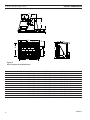
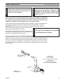
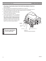
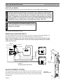
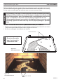
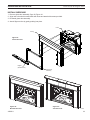
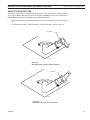
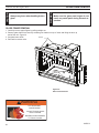
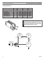
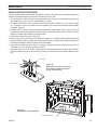
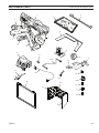
ILDV Series Direct Vent Gas Fireplace Insert Models: iLDV20NV & iLDV20PV ILDV30NV & ILDV30PV ILDV40NV & ILDV40PV WARNING If the information in these instructions is not followed exactly, a fire or explosion may result causing property damage, personal injury or loss of life. – Do not store or use gasoline or other flammable vapors and liquids in the vicinity of this or any other appliance. – WHAT TO DO IF YOU SMELL GAS • Do not try to light any appliance. • Do not touch any electrical switch; do not use any phone in your building. •Immediately call your gas supplier from a neighbor's phone. Follow the gas supplier's instructions. •If you cannot reach your gas supplier, call the fire department. –Installation and service must be performed by a qualified installer, service agency or the gas supplier. WARNING: Improper installation, adjustment, alteration, services or maintenance can cause injury or property damage. Refer to this manual. For assistance or additional information consult a qualified installer, service agency or the gas supplier. This appliance may be installed in an aftermarket*, permanently located, manufactured home (USA only) or mobile home, where not prohibited by local codes. This appliance is only for use with the type of gas indicated on the rating plate. This appliance is not convertible for use with other gases, unless a certified kit is used. * Aftermarket: Completion of sale, not for purpose of resale, from the manufacturer. Installation and Operating Instructions 0511 ILDV cover 9/08 DUE TO HIGH TEMPERATURES, THE APPLIANCE SHOULD BE LOCATED OUT OF TRAFFIC AND AWAY FROM FURNITURE AND DRAPERIES. CHILDREN AND ADULTS SHOULD BE ALERTED TO THE H A Z A R D S O F HI G H S U R FA CE TEMPERATURE AND SHOULD STAY AWAY TO AVOID BURNS OR CLOTHING IGNITION. YOUNG CHILDREN SHOULD BE SUPERVISED WHEN THEY ARE IN THE SAME ROOM AS THE APPLIANCE. CLOTHING OR OTHER FLAMMABLE MATERIAL SHOULD NOT BE PLACED ON OR NEAR THE APPLIANCE. Keep the room area clear and free from combustible materials, gasoline, and other flammable vapors and liquids. INSTALLER: Leave this manual with the appliance. CONSUMER: Retain this manual for future reference. 83D0511 8/11 Rev. 8 ILDV20/30/40 Fireplace Insert CONTENTS Important Safety Information.......................................3 Check Gas Pressure...................................................18 Code Approval...............................................................4 Electrical Installation..................................................19 Electrical Wiring......................................................19 Remote Wall Mounted Switch.................................19 Hand Held Remote Control.....................................19 Product Features High Elevations.........................................................5 Gas Pressures..........................................................5 Gas Specifications....................................................5 Log Placement.............................................................20 Insert Dimensions.........................................................6 Surround Installation..................................................23 Installation Information.................................................7 Before You Start........................................................7 Insert Applications.....................................................7 Clearances................................................................7 Operating Instructions................................................24 Lighting Pilot for the First Time...............................24 Lighting Pilot...........................................................25 Lighting Burner........................................................26 To Turn Off Gas.......................................................26 Adjusting Blower Speed..........................................26 Clearances.....................................................................8 Insert Clearances......................................................8 Mantel Clearances....................................................8 Hearth Requirements................................................8 Installation......................................................................9 Insert Placement.......................................................9 Zero-Clearance Fireplace Requirements................10 Venting Installation......................................................11 Installation Precautions...........................................11 Venting Requirements.............................................12 Altitude Considerations...........................................13 Venting Configurations............................................14 Manifold Removal and Installation..........................15 Insert Installation.........................................................16 Check Gas Type.....................................................16 Install Gas to Insert Location..................................16 Installation Items Needed.......................................16 Air Shutter Adjustment...............................................27 Glass Replacement.....................................................28 Blower Removal and Assembly.................................29 Blower Parts............................................................30 Cleaning and Maintenance.........................................31 Venting System.......................................................31 Pilot and Burner Flames.........................................31 Firebox Cleaning.....................................................32 Maintaining Your Heater's Appearance...................32 Yearly Service Procedure........................................33 Troubleshooting..........................................................34 Replacement Parts......................................................35 Optional Accessories..............................................37 For Massachusetts Residents ONLY.........................38 Warranty.......................................................................39 Efficiencies..................................................................40 83D0511 IMPORTANT SAFETY INFORMATION INSTALLER WARNING Please leave these instructions with the appliance. ILDV20/30/40 Fireplace Insert OWNER Please retain these instructions for future reference. • Read this owner’s manual carefully and completely before trying to assemble, operate, or service this fireplace. • Any change to this fireplace or its controls can be dangerous. • Improper installation or use of this fireplace can cause serious injury or death from fire, burns, explosions, electrical shock and carbon monoxide poisoning. This fireplace is a vented product. This fireplace must be properly installed by a qualified service person. The glass door must be properly seated and sealed. If this unit is not properly installed by a qualified service person with glass door properly seated and sealed, combustion leakage can occur. CARBON MONOXIDE POISONING: Early signs of carbon monoxide poisoning are similar to the flu with headaches, dizziness and/or nausea. If you have these signs, the fireplace may not have been installed properly. Get fresh air at once! Have the fireplace inspected and serviced by a qualified service person. Some people are more affected by carbon monoxide than others. These include pregnant women, people with heart or lung disease or anemia, those under the influence of alcohol, and those at high altitudes. Propane/LP gas and natural gas are both odorless. An odor-making agent is added to each of these gases. The odor helps you detect a gas leak. However, the odor added to these gases can fade. Gas may be present even though no odor exists. Make certain you read and understand all warnings. Keep this manual for reference. It is your guide to safe and proper operation of this fireplace. 1. This appliance is only for use with the type of gas indicated on the rating plate. This appliance is not convertible for use with other gases unless a certified kit is used. 2. For propane/LP fireplace, do not place propane/LP supply tank(s) inside any structure. Locate propane/LP supply tank(s) outdoors. To prevent performance problems, do not use propane/LP fuel tank of less than 100 lbs. capacity. 3. If you smell gas • shut off gas supply. • do not try to light any appliance. • do not touch any electrical switch; do not use any phone in your building . • immediately call your gas supplier from a neighbor’s phone. Follow the gas supplier’s instructions. 83D0511 4. Never install the fireplace • in a recreational vehicle • where curtains, furniture, clothing, or other flammable objects are less than 36" from the front, top, or sides of the fireplace • in high traffic areas • in windy or drafty areas 5. This fireplace reaches high temperatures. Keep children and adults away from hot surfaces to avoid burns or clothing ignition. Fireplace will remain hot for a time after shutdown. Allow surfaces to cool before touching. 6. Carefully supervise young children when they are in the room with fireplace. 7. Do not modify fireplace under any circumstances. Any parts removed for servicing must be replaced prior to operating fireplace. 8. Turn fireplace off and let cool before servicing, installing, or repairing. Only a qualified service person should install, service, or repair the fireplace. Have burner system inspected annually by a qualified service person. 9. You must keep control compartments, burners, and circulating air passages clean. More frequent cleaning may be needed due to excessive lint and dust. Turn off the gas valve and pilot light before cleaning fireplace. 10. Have venting system inspected annually by a qualified service person. If needed, have venting system cleaned or repaired. Refer to Cleaning and Maintenance, Page 31. 11. Keep the area around your fireplace clear of combustible materials, gasoline, and other flammable vapor and liquids. Do not run fireplace where these are used or stored. Do not place items such as clothing or decorations on or around fireplace. 12. Do not use this fireplace to cook food or burn paper or other objects. 13. Never place anything on top of fireplace. Continued on page 4 IMPORTANT SAFETY INFORMATION & code approval Continued from page 3 14. Do not use any solid fuels (wood, coal, paper, cardboard, etc.) in this fireplace. Use only the gas type indicated on rating plate. 15. This appliance, when installed, must be electrically grounded in accordance with local codes or in the absence of local codes, with the National Electrical Code, ANSI/NFPA 70, or the Canadian Electrical Code, CSA C22.1. 16. Do not obstruct the flow of combustion and ventilation air in any way. Provide adequate clearances around air openings into the combustion chamber along with adequate accessibility clearance for servicing and proper operation. 17. Do not use fireplace if any part has been exposed to or has been under water. Immediately call a qualified service technician to inspect the appliance and replace any part of the control system and any gas control which as been submerged in water. 18. Do not operate fireplace if any log is broken. 19. Do not use a blower insert, heat exchanger insert, or any other accessory not approved for use with this fireplace. 20. Do not operate the fireplace with glass door removed, cracked, or broken. Code Approval Direct Vent type appliances draw all combustion air from outside of the dwelling through the vent pipe. IMPORTANT: PLEASE READ THE FOLLOWING CAREFULLY It is normal for fireplaces fabricated of steel to give off some expansion and/or contraction noises during the start up or cool down cycle. Similar noises are found with your furnace heat exchanger or car engine. IMPORTANT: PLEASE READ THE FOLLOWING CAREFULLY It is not unusual for gas fireplaces to give off some odor the first time it is burned. This is due to the manufacturing process. Please ensure that your room is well ventilated during burn off — open all windows. It is recommended that you burn your fireplace for at least ten (10) hours the first time you use it. Place the fan switch in the “OFF” position during this time. WARNING ILDV20/30/40 Fireplace Insert Never connect unit to private (non-utility) gas wells. This gas is commonly known as wellhead gas. These appliances have been tested by CSA and found to comply with the established standards for DIRECT VENT GAS FIREPLACE HEATERS in the USA and Canada as follows: LISTED VENTED GAS FIREPLACE HEATER TESTED TO: ANSI Z21.88-2009/CSA 2.33-2009 STANDARDS A manufactured home (USA only) or mobile home OEM installation must conform with the Manufactured Home Construction and Safety Standard, Title 24 CFR, Part 3280, or when such a standard is not applicable, the Standard for Manufactured Home Installations, ANSI/ NCSBCS A225.1, or Standard for Gas Equipped Recreational Vehicles and Mobile Housing, CSA Z240.4. ! WARNING HOT GLASS WILL CAUSE BURNS. DO NOT TOUCH GLASS UNTIL COOLED. NEVER ALLOW CHILDREN TO TOUCH GLASS. 83D0511 product features ILDV20/30/40 Fireplace Insert product SPECIFICATIONS • This appliance has been certified for • • • • • • use with either natural or propane gas. Refer to the appropriate data plates. This appliance is not for use with solid fuels. The appliance is approved for bedroom or bedsitting room installations. The appliance must be installed in accordance with local codes if any. If none exist use the current installation code. ANSI Z223.1/NFPA 54 in the USA, CSA B149 in Canada. This appliance is mobile home approved. The appliance must be properly connected to a venting system. The appliance is not approved for closet or recessed installations. Blower Gas ShutOff Valve Blower Knob ON/OFF Switch OFF/Pilot/ON Knob Figure 1 ILDV Series Fireplace Insert HI/LO Knob Piezo HIGH ELEVATIONS Input ratings are shown in BTU per hour and are certified without deration for elevations up to 4,500 feet (1,370 m) above sea level. For elevations above 4,500 feet (1,370 m) in USA, installation must be in accordance with the current ANSI Z223.1/NFPA 54 and/or local codes having jurisdiction. In Canada, please consult provincial and/or local authorities having jurisdiction for installation at elevations above 4,500 feet (1,370 m). GAS pressures Inlet Minimum Inlet Maximum Manifold Pressure 83D0511 Natural Propane (LP) 4.5” w.c. 11.0” w.c. 10.5” w.c. 13.0” w.c. 3.5” w.c. 10.0” w.c. Gas Specifications & ORIFICE SIZE FP1919 ILDV parts 9/08 Max.Input Min. Input Orifice Model Fuel BTU/h BTU/h Size ILDV20NV Nat.20,000 13,000 #44 ILDV20PV LP20,000 16,000 1.35 mm ILDV30NV Nat. 30,00020,500 #37 ILDV30PV LP 30,00023,000 #51 ILDV40NV Nat. 39,00027,000 #31 ILDV40PV LP 38,000 30,000 #49 NOTE: The ILDV Series fireplace inserts work without any electrical supply. The blower must be attached to 110/120V AC. insert dimensions ILDV20/30/40 Fireplace Insert I G H J K C L D F B E A Figure 2 ILDV Fireplace Insert Dimensions 0511 ILDV dims Ref.ILDV20ILDV30ILDV40 A21Z\v" (540 mm)25Z\v" (641 mm)28Z\v" (718 mm) 9/08 B 13C\zn" C 13M\," D24" E 17M\," F 6Z\v" G 16B\," H 8C\," I 3Z\," J2Z\," K 6C\," L2C\v" (335 mm) 16C\zn" (352 mm) 14B\," (610 mm)28Z\," (454 mm)20C\v" (159 mm) 6Z\v" (422 mm)20C\zn" (213 mm) 9M\," (79 mm) 4" (54 mm)2C\zn" (162 mm) 7B\," (70 mm) 3" (411 mm) 18Z\," (372 mm) 15C\," (714 mm) 31C\zn" (527 mm)23C\," (159 mm) 6Z\v" (513 mm)22Z\x" (251 mm) 11Z\v" (102 mm) 5Z\," (56 mm)2ZC\zn" (194 mm) 8Z\v" (76 mm) 3" (460 mm) (391 mm) (792 mm) (594 mm) (159 mm) (572 mm) (286 mm) (130 mm) (71 mm) (210 mm) (76 mm) 83D0511 general installation INFORMATION ILDV20/30/40 Fireplace Insert Before You Start Read this homeowner manual thoroughly and follow all instructions carefully. Inspect all contents for shipping damage and immediately inform your dealer if any damage is found. Do not install any unit with damaged, incomplete, or substitute parts. Check your packing list to verify that all listed parts have been received. The following factors should be taken into consideration: • This insert should have sufficient access for its safe operation and maintenance. • The flow of combustion and ventilation air must not be obstructed. • Minimum clearances to combustibles, such as mantels, must be maintained. Refer to Pages 8 and 9, Figures 3 and 4. • Never obstruct the front opening of the insert. • Do not install in the vicinity where gasoline or other flammable liquids may be stored. • These units can be installed in a bedroom. Refer to National Fuel Gas Code ANSI Z233.1/ NFPA 54 (current edition), the Uniform Mechanical Code (current edition), and Local Building Codes for specific installation requirements. IMPORTANT: Your direct vent insert was designed to be installed in an existing wood burning fireplace. The location and clearances are subject to local building codes. INSERT APPLICATIONS Before installing the gas fireplace insert, consider the functioning needs of the fireplace. Confirm the size of the fireplace cavity, the design of the chimney, and the availability of the gas supply and electricity for the insert fan. IMPORTANT: Your direct vent insert is designed to be only vented vertically with a minimum height of 10 feet. When the unit is installed into a wood burning fireplace, the minimum distance the mantel can be placed above the fireplace is governed by local building codes applicable to wood burning fireplaces. Consult local authorities having jurisdiction for these clearances. The underside of the mantel will become warm. Use only finishes which are heat resistant and do not discolor. WARNING CLEARANCES MINIMUM FIREPLACE SIZE/CLEARANCES TO COMBUSTIBLES The dimensions shown on Pages 8 and 9, Figures 3 and 4, are minimum clearances to maintain when installing this heater. Follow these instructions carefully to ensure safe installation. Failure to follow instructions exactly can create a fire hazard. 83D0511 clearances ILDV20/30/40 Fireplace Insert INSERT Clearances no combustibles (ie: drapes, doors) may be within, or swing within 36" of the front of the insert. Co mb To p F ing tib le Ma nte l Side Facing Side Wall ac us 12” (305 mm) 9” (228 mm) 12” (305 mm) Maximum Depth 3/4” (19 mm) Maximum Depth Combustible Facing NOTE: Side clearance to combustibles is 10" (254 mm) from opening whether it is side wall or mantel legs. 10” (254 mm) Minimum 12” (305 mm) Minimum 42” (1067 mm) Minimum FP1947 Figure 3 Mantel Clearances mantel clearances NOTE: The combustible area above the facing must not protrude more than 3/4" from the facing. If it does, it is considered a mantel FP1947and must meet the mantel requirements listed in this manual. insert clearances HEARTH REQUIREMENTS 9/08 The insert must be installed on a noncombustible hearth extending a minimum of 12" from the fireplace opening (local codes may require a larger hearth). The hearth must also extend to both sides of the face (Refer to the table on Page 7). 83D0511 INSTALLATION ILDV20/30/40 Fireplace Insert INSERT PLACEMENT • The insert must be placed within a code-conforming masonry fireplace or a tested and listed zero-clearance (UL-127, solid fuel) fireplace. Repair any fireplace damage prior to installation. • Because the insert uses a circulation blower, clean the fireplace, smoke shelf and chimney before installing. • This heater may be placed in a bedroom. Please be aware of the large amount of heat this appliance produces when determining a location. 18" 15Z\," 21" 18" 22Z\x" 28" 14" 16" ILDV30 ILDV20 23" Figure 4 Minimum Openings 23Z\x" 31" 16Z\x" ILDV40 fp1959 FIREBOX DIMS 83D0511 installation ILDV20/30/40 Fireplace Insert ZERO-CLEARANCE (METAL) FIREPLACE REQUIREMENTS • The damper and grate must be removed. • The smoke shelf, internal baffles, screen, refractory and metal or glass doors may be removed (if applicable). • Do not remove or alter the insulation or any structured rigid frame members (metal sides, floor, door frames, face of the fireplace, etc.). WARNING • Installer must attach red warning plate to the inside of the firebox of fireplace with screws supplied. • Do not cut any sheet metal parts of the fireplace in which this gas fireplace insert is installed. THIS IS STRICTLY PROHIBITED! • If factory-built fireplace has no gas access hole(s) provided, drill a 1.5" (37.5 mm) or less through lower sides or bottom of firebox. You must plug the access hole with noncombustible insulation after gas supply line has been installed. • If your factory-built fireplace has air passages on the face for zero clearance, DO NOT BLOCK THESE PASSAGES! Insulation Sm Shelf Screen Masonry Lining or Refractory r pe m Da al rn te es In affl B Metal or Glass Doors oke Grate Masonry Lining or Refractory Figure 5 Metal Fireplace Zero-Clearance Requirements &P ZEROCLEARANCEREQUIREMENTS IMPORTANT: Please review the following carefully. It is normal for inserts fabricated of steel to give off some expansion and/or contraction noises during the start up or cool down cycle. Similar noises are found with your furnace heat exchanger or car engine. It is not unusual for your insert to give off some odor the first time it is burned. This is due to the curing of the paint and any undetected oil from the manufacturing process. Please ensure that your room is well ventilated. OPEN ALL WINDOWS DURING INITIAL BURN OFF/CURING PHASE. Burn your insert for at least six (6) hours on "HIGH" the first time you use it. Place the fan in the "OFF" position during this time. 10 83D0511 NOTICE WARNING VentING installation ILDV20/30/40 Fireplace Insert Read all instructions completely and thoroughly before attempting installation. Failure to do so could result in serious injury, property damage or loss of life. Operation of improperly installed and maintained venting system could result in serious injury, property damage or loss of life. Failure to follow these instructions will void the warranty. INSTALLATION PRECAUTIONS Consult local building codes before beginning the installation. The installer must make sure to select the proper vent system for installation. Before installing vent kit, the installer must read this insert manual and vent kit instructions. Only a qualified installer/service person should install venting system. The installer must follow these safety rules: • Wear gloves and safety glasses for protection. • Use extreme caution when using ladders or when on rooftops. • Be aware of electrical wiring locations in walls and ceiling. The following actions will void the warranty on your venting system: WARNING • • • • Installation of any damaged venting component. Unauthorized modification of the venting system. Installation of any component part not manufactured or approved by MHSC. Installation other than permitted by these instructions. This insert must be vented to the outside. The venting system must NEVER be attached to a chimney serving a separate solid fuel burning appliance. Each gas appliance must use a separate vent system. Do not use common vent systems. 83D0511 11 venting installation ILDV20/30/40 Fireplace Insert WARNING VENTING REQUIREMENTS • Make sure the exhaust pipe on heater connects to exhaust portion of cap. Attach flex liners. Figure 6 • Do not crimp or rupture liner when bending it into chimney offsets. • The exhaust vent must reline the entire length of chimney and terminate above chimney top. • Vent must meet all vent manufacturer's requirements when installed. • Make sure you have the following before installing unit: • 3" and 3" UL 1777 Listed gas liner for air inlet and exhaust. • Vertical Terminations kits: ILDV20/ILDV30: HEDV32T812, HEDV32T1212, HEDVRT, AI31TK33A ILDV40: HEDV32T812, HEDV32T1212, HEDVRT Figure 6 Venting Unit Inlet Exhaust Maximum Height 40' (12.9 m) Minimum Height 10' (3 m) FP1922 12 FP1922 vent requirements 9/08 83D0511 venting installation ILDV20/30/40 Fireplace Insert ALTITUDE CONSIDERATIONS WARNING This heater has been tested at altitudes ranging from sea level to 4,500 feet (1,370 m). In this testing, heater with standard orifice burns correctly with just an air shutter adjustment. If you need to resize orifice for use at high altitude, contact your dealer. Failure to adjust air shutter properly may lead to improper combustion which can create a safety hazard. Consult your dealer or installer if you suspect an improperly adjusted air shutter. Termination Kit (Refer to Page 12) High Temp Silicone Apply high-temperature silicone to lines on both ends and secure with two (2) screws FP1923 3" and 3" UL 1777 Gas Liner Figure 7 Connecting Vent Pipe to Heater FP1923 exhaust pipe 9/08 83D0511 13 venting installation ILDV20/30/40 Fireplace Insert VENTING CONFIGURATIONS Termination Kits (Refer to Page 12) Exhaust Inlet 3" (75 mm) Exhaust UL 1777 Gas Liner 3" (75 mm) Inlet Recommended block-off plate (noncombustible metal). Prevents odors from chimney entering room. UL 127 Solid Fuel Z.C Firebox FP1924 Figure 8 Inlet and Exhaust Reline FP1924 NOTE: You may use either reline configuration with a masonry inlet exhaust reline or zero-clearance fireplace. 9/08 14 83D0511 venting installation ILDV20/30/40 Fireplace Insert INTAKE MANIFOLD VENT INSTALLATION Before insert is placed back into fireplace opening, attach intake flex pipe to intake manifold, located in rear lower left corner with hose clamp (not supplied) or other approved method. EXHAUST MANIFOLD REMOVAL AND VENT INSTALLATION The exhaust manifold is shipped attached to insert. It may be removed to allow tight installation. 1. Remove glass door assembly following instructions on Page 29, Figure 33. 2. Lightly tap on flange of exhaust baffle assembly towards you until disengaged. Remove baffle, manifold and gasket from unit. Figure 9 3. ILDV20: Attach the solid closed baffle plate. ILDV30: Attach the slotted baffle plate. ILDV40: There is no adjustable baffle on the ILDV40, however, attach the slotted baffle plate for extended vertical applications only if needed to improve flame appearance.. Figure 10 4. Feed exhaust flex through hole on top of insert and attach to manifold with hose clamp (not provided) or other approved methods (check local codes). Insure the gasket is in place before securing the flex to the manifold. 5. Re-attach exhaust baffle and manifold assembly in reverse order of Step 2. 6. Re-attach glass door in reverse order. NOTE: The ILDV30 has an adjustable baffle and may be adjusted as needed by loosening four (4) screws. Figure 11. When using the baffle on the ILDV40 to improve flame appearance, the baffle is used in the open position only. Gasket Flex Vent Manifold Baffle Assembly FP1960 Side View Front View Figure 9 Remove Manifold and Attach to Flex Vent FP1961 Baffle Plate (For ILDV20) Loosen Four (4) Screws to Adjust FP1960 manifold assembly 9/08 Bottom View Closed Position FP2156 Closed Baffle Plate Must use on ILDV20 for All VerBaffle tical Applications Assembly Baffle Assembly fp2156ILDV20 ILDVBaffle baffle assembly Plate Figure 10 12/08 Baffle Assembly and Adjustment NOTE: Make sure the correct baffle plate is used. 83D0511 Bottom View Open Position ILDV30 - Baffle Plate FP1961 ILDV30: Adjust for extended vertical applications. baffle adjustment 9/08 ILDV40 Baffle Plate With Baffle Plate for Extended Vertical Applications FP2640 Use Fully Open ONLY 15 ILDV40 baffle No Baffle Plate INSERT INSTALLATION ILDV20/30/40 Fireplace Insert check gas type Use proper gas type for the insert you are installing. If you have conflicting gas type, do not install insert. See dealer where you purchased the insert for proper insert according to your gas type. WARNING A qualified installer or service person must connect appliance to gas supply. Follow all local codes. CAUTION Install gas piping to insert location For propane/LP units, never connect insert directly to the propane/LP supply. This burner system requires an external regulator (not supplied). Install the external regulator between the burner system and propane/LP supply. installation items needed Make sure you have the items listed below before installing appliance. • External regulator (supplied by installer) • Piping (check local codes) •Test gauge connection* • Sealant (resistant to propane/LP gas) • Sediment trap (optional but recommended) • Tee joint • Pipe wrench • approved flexible gas line with gas connector (if allowed by local codes — not provided) * A CSA design-certified equipment shutoff valve with 1/8" NPT tap is an acceptable alternative to test gauge connection. Purchase the CSA design-certified equipment shutoff valve from your dealer. For propane/LP connections only, the installer must supply an external regulator. The external regulator will reduce incoming gas pressure. You must reduce incoming gas pressure to between 11 and 13 inches of water. If you do not reduce incoming gas pressure, burner system regulator damage could occur. Install external regulator with the vent pointing down as shown in Figure 11. Pointing the vent down protects it from freezing rain or sleet. 100 gal. (min. Propane/LP Supply Tank CAUTION External Regualtor Vent Pointing Down Use only new black iron or steel pipe. Internally tinned copper or copper tubing can be used per National Fuel Gas Code, Section 2.6.3, providing gas meets hydrogen sulfide limits, and where permitted by local codes. Gas piping system must be sized to provide minimum inlet pressure (listed on data plate) at the maximum flow rate (BTU/hr). Undue pressure loss will occur if the pipe is too small. FP1930 Figure 11 - External Regulator with Vent Pointing Down (Propane/LP Only) 16 &0 EXTERNALREGULATOR 83D0511 ILDV20/30/40 Fireplace Insert Only persons licensed to work with gas piping may make the necessary gas connections to this appliance. CAUTION WARNING INSERT installation A manual shut-off valve is factory installed upstream of the appliance. Union tee and plugged 1/8" NPT pressure tapping point should be installed upstream of the appliance. Figure 12 NOTE : The gas line connection may be made using 1/2" rigid tubing or an approved flex connector. Since some municipalities have additional local codes it is always best to consult your local authorities and the current edition of the National Fuel Gas Code ANSI.Z223.1, NFPA54. In Canada CSA-B149 (1 or 2) Installation Code. A listed manual shutoff is factory installed upstream of appliance. Union tee and plugged 1/8" NPT pressure tapping point should be installed upstream of the appliance. Figure 12 Check your building codes for any special requirements for locating equipment shutoff valve to inserts. Apply pipe joint sealant lightly to threads. This will prevent excess sealant from going into pipe. Excess sealant in pipe could result in clogged burner system valves. CAUTION IMPORTANT: The main gas valve is for turning on or shutting off the gas to the insert. Use pipe joint sealant that is resistant to liquid petroleum (LP) gas. We recommend that you install a sediment trap/drip leg in supply line as shown in Figure 12. Locate sediment trap/drip leg where it is within reach for cleaning. Install in piping system between fuel supply and burner system. Locate sediment trap/drip leg where trapped matter is not likely to freeze. A sediment trap traps moisture and contaminants. This keeps them from going into the burner system gas controls. If sediment trap/drip leg is not installed or is installed wrong, burner system may not run properly. Approved Flexible Gas Line Supplied with Appliance Natural Gas From Gas Meter (4.5" w.c. to 10.5" w.c. Pressure) Propane/LP From External Regulator (11" w.c. to 13" w.c. Pressure) Tee Joint Pipe Nipple Figure 12 Gas Connection 83D0511 Cap FP1931 gas connection 9/08 3" Mi nim um 17 CHECK GAS PRESSURE ILDV20/30/40 Fireplace Insert 1. Check gas type. The gas supply must be the same as stated on the appliance’s rating decal. If the gas supply is different from the fireplace, STOP! Do not install the appliance. Contact your dealer immediately. 2. Install and attach flex line provided with on this appliance to 1/2" gas line. 3. After completing gas line connection, purge air from gas line and test all gas joints from the gas meter to the fireplace for leaks. Use a soap and water solution or a gas sniffer. 4. To adjust flame height, turn HI/LO knob to HI to get maximum pressure to burner. Turn HI/LO knob to LO to get minimum pressure. 5. To check gas pressures at valve, turn captured screw counter clockwise 2 or 3 turns and then place tubing to pressure gauge over test point. Turn unit to high. Figure 13. After taking pressure reading, be sure and turn captured screw clockwise firmly to reseal. Do not over torque. Check test points for gas leaks with a soap and water solution or an electronic gas leak detector. Pressure Test "IN" FP1932 WARNING Pressure Test "OUT" HI/LO Knob Do not use open flame to check for gas leaks. Pilot Adjustment Screw Figure 13 Gas Pressure Check at Gas Valve FP1932 valve regulator with knobs 18 83D0511 ELECTRICAL INSTALLATION ILDV20/30/40 Fireplace Insert Electrical Wiring CAUTION WARNING This insert will work without any electrical supply. Electricity is only needed to operate blower. Electrical connections should only be performed by a qualified, licensed electrician. Main power must be off when connecting to main electrical power supply or performing service. All wiring shall be in compliance with all local, city and state codes. The appliance, when installed, must be electrically grounded in accordance with local codes, or in the absence of local codes, with the National Electrical Code ANSI/NFPA 70 (latest edition) and Canadian Electrical Code, CSA C22.1. Label all wires before disconnecting when servicing controls. Wiring errors can cause improper and dangerous operation. Verify proper operation after servicing. Remote Wall mounted Switch A remote wall switch and up to fifteen (15) feet of 18 Ga. wire may be used with this appliance. Attach the wall switch in a junction box at the desired location on the wall. Figure 14. NOTE: Extended lengths of wire may cause the fireplace not to function properly. Longer length of wire is permitted if the wire is made out of larger gauge (diameter) wire. Always check with local code. Sparker Thermocouple Pilot Assembly Piezo Igniter Switch ON Optional 15' Wall Switch OFF ON HI ON OFF PILOT Thermopile LO OFF TH TP TH/TP Millivolt Valve Optional Remote Control ON Figure 14 Wiring Diagram for Wall Switch OFF Remote Receiver HAND HELD REMOTE CONTROL The remote control receiver may be installed in the control panel by removing the ON/OFF switch and the knock-out plate. Slide the receiver into the space where the knock-out plate was removed. FP1933Refer to remote instructions for wiring and operation. wall switch wiring Figure 15 Remote Receiver FP2177 83D0511 19 FP2177 remote receiver log placement ILDV20/30/40 Fireplace Insert WARNING Before you begin - This unit is supplied with six (6) ceramic fiber logs. Do not handle these logs with your bare hands. Always wear gloves to prevent skin irritation from ceramic fibers. After handling the logs, wash your hands gently with soap and water to remove any traces of fibers. The positioning of the logs is critical to the safe and clean operation of this heater. Sooting and other problems may result if the logs are not properly and firmly positioned in the appliance. Never add additional logs or embellishments such as pine cones or vermiculite to the heater. Only use the logs supplied with the unit. Failure to position the parts in accordance with diagrams below or to use only parts specifically approved for this heater may result in property damage or personal injury. INSTALL LOGS AND ROCK WOOL (EMBER MATERIAL) IN FIREBOX 1. Break up rock wool (ember material) into dime-sized pieces. Place evenly as shown. Do not exceed 1" layer covering all round burner ports. Refer to Figures 16a and 16b. 2. Do not cover rectangular slots located at rear of burner. WARNING Ember Material Area Do not use the entire bag of rock wool to cover burner area. Figure 16a Ember Material Area FP1968 FP1968 ember material area 9/08 LG536 Figure 16b Place Ember Material Ember Material 83D0511 20 LG536 ILDV log placement ILDV20/30/40 Fireplace Insert Figure 17 Place Log #6 3. Align the two pin holes on Log #6 onto the burner. Figure 17 LG537 Log #6 LG537 ILDV log 6 Figure 18 9/08 Log #1 Place Log #1 4. Place log #1 by aligning the holes to the burner pin. Figure 18 LG538 LG538 log #1 9/08 LogILDV #2 Figure 19 Place Log #2 5. Position log #2 so that it is resting on log #1. Figure 19 LG539 83D0511 LG539 ILDV log #2 9/08 21 log placement ILDV20/30/40 Fireplace Insert Log #3 6. ILDV20: Position log #3 so the bottom right end is resting behind log #2 and the left end is resting on the flat area on log #2. ILDV30/40: Position log #3 so that the bottom right end is resting on the pad on log #2 and the left end is resting on the flat spot on log #1. Figure 20 Figure 20 Place Log #3 LG540 LG540 ILDV log #3 9/08 Log #4 Figure 21 Place Log #4 7. Align log #4 hole to the burner pin and rest on log #1. Figure 21 LG541 8. Align the cutout on the bottom LG541 of log #5 and fit it into log #4. Figure 22 Log #5ILDV log #4 9/08 Figure 22 Place Log #5 LG542 83D0511 22 LG542 surround installation ILDV20/30/40 Fireplace Insert INSTALL SURROUND 1. Remove glass door assembly. Page 29, Figure 34 2. Align cast or beveled surround holes with insert and attach with screws provided. 3. Re-attach glass door assembly. 4. Attach filigree to face by gently pushing into place. Insert Facing Figure 23 Install Surround FP1962 Filigree (Floral Shown) Glass Door Assembly FP1962 install surround 9/08 Figure 24 Beveled Surround Figure 25 Cast Surround 83D0511 FP1934 23 FP1934 OPERATING INSTRUCTIONS ILDV20/30/40 Fireplace Insert WARNING for your safety read before lighting If you do not follow these instruction exactly, a fire or explosion may result causing property damage, personal injury or loss of life. A. This appliance is equipped with a pilot which must be lit with built-in piezo ignitor while following these instructions exactly. B. BEFORE OPERATING smell all around the appliance area for gas. Be sure to smell next to the floor because some gas is heavier than air and will settle on the floor. WHAT TO DO IF YOU SMELL GAS: • Turn off all gas to the appliance. • Open windows. • Do not attempt to light any appliance. • Do not touch any electric switch; do not use any phone in your building. • Immediately call your gas supplier from a neighbor's phone. Follow the gas supplier's instructions. • If you cannot reach your gas supplier, call the fire department. C. Use only your hand to push in, or turn the gas control knob. Never use tools. If the knob will not push in or turn by hand, don't try to repair it. Call a qualified service technician. Force or attempted repair may result in a fire or explosion. D. Do not use this appliance if any part of it has been under water. Immediately call a qualified service technician to inspect the appliance and to replace any part of the control system and any gas control that has been under water. WARNING Lighting pilot for the first time initial lighting Never use an open flame to Purge air from the supply line as follows: check for gas leak. • Open main shutoff valve. • Unscrew main pressure test point. • Leave inlet test screw open until gas comes in. • When gas is flowing, tighten inlet screw immediately. leak testing 1. Follow the pipe from the gas supply line connection to the gas valve. Check connection for leaks with soap and water mixture. 2. Next check for gas leaks at the burner with soap and water mixture. 3. Check the pilot for gas leaks with soap and water mixture. 24 83D0511 OPERATING INSTRUCTIONS ILDV20/30/40 Fireplace Insert Lighting pilot for the first time You may check for gas leaks with the following methods only: • Soap and water solution • An approved leak testing spray WARNING approved leak testing method If using a soap and water solution to test for leaks, DO NOT spray solution onto control body. danger • Electronic sniffer Never check for gas leak with open flame! NOTE: Remove any excessive pipe compound from the connections. Excessive pipe compound can set off electronic sniffers. Check for gas leaks in each of the following locations: • Pipe from the gas supply line connection to the gas valve • Burner connections • Field made joints / gas shutoff valve • Pilot • Factory made joints • Each joint or connection • All joints on valve and control body WARNING Lighting pilot The control has an interlock device that does not allow the lighting of the fireplace up to the moment the safety device of the flame has not interrupted the gas flow. After that period of time (when the magnet is closed), it is possible to start the lighting operation. The gas control knob is designed to be operated by hand. DO NOT use any tools during this operation. Damaged knobs may result in serious injury. 1. Depress and turn knob counterclockwise to pilot position. WARNING 83D0511 F PILOT ON OF 2. Depress fully and hold pilot gas knob. Depress piezo igniter as many times as needed to ignite pilot. Keep knob fully depressed for a few seconds. Release and check that pilot continues to burn. If the knob does not "pop" If the pilot does not stay lit, out to its original position repeat steps 1 and 2. when released, turn off gas to appliance and contact qualified service technician. PIL OT Figure 26 - Pilot Position Continued on next page 25 OPERATING INSTRUCTIONS ILDV20/30/40 Fireplace Insert Lighting burner main burner switch The “ON/OFF” switch for the main burner can be found on the right side of insert surround. This switch allows you to turn on and to turn off the main burner without using the gas valve knob. Make sure the button is in the “ON” position to light the main burner. Figure 27 Lighting the burner Depress and turn the knob counterclockwise than four (4) seconds for the burner to ignite. to the “ON” position. Figure 28 It will take less Pilot position Depress and turn knob to pilot position to keep burner off while maintaining the pilot light. Figure 29 PILOT ON F P ILOT Figure 27 On/Off Switch OFF F OF ON OF ON PIL PIL OT OT Figure 28 - On Position Figure 29 - Pilot Position to turn off gas FP1937 Depress and turn knob clockwise tocontrol “OFF”knob posi-on tion. Figure 30 ON OFF PI L O T PIL OT Figure 30 - Off Position adjusting blower speed The internal blower helps transfer heat from heater into room. It will not turn on until heater is up to temperature (approximately 10 minutes after starting). To turn blower off, turn knob all the way counterclockwise . One click clockwise turns blower to high speed. Turning knob clockwise from high position decreases speed of blower. Figure 31 Figure 31 - Blower Knob 83D0511 26 FP1939 fan control knob AIR SHUTTER ADJUSTMENT (NATURAL GAS ONLY) ILDV20/30/40 Fireplace Insert ADJUST THE AIR SHUTTER The venturi of the burner is equipped with an air shutter. The opening of the venturi has been set at 1/4" for Natural Gas and fully open for Propane installation at sea level. The burner on Natural Gas models may be adjusted for high altitude as follows: • To increase air mixture, open the shutter more. This will reduce soot formation. Figure 32 • To decrease air mixture, close the shutter. Flames will be more yellow. Figure 33 Air Shutter FP1940 Figure 32 Push Adjustment Lip Up to Open Air Shutter FP1940 air shutter part open Air Shutter FP1941 Figure 33 Pull Adjustment Lip to Close Air Shutter FP1941 air shutter fully open 83D0511 27 GLASS FRAME REMOVAL Always use gloves when handling broken glass. WARNING CAUTION ILDV20/30/40 Fireplace Insert Make sure the glass panel edges do not touch any metal parts during thermal expansion. GLASS FRAME REMOVAL 1. Carefully remove upper filigree by pulling straight out. 2. Remove glass frame from insert by releasing two latches on top of insert and lifting the door up and off the unit. Figure 34 3. Set glass frame aside. Latches 4. Re-install in reverse order. FP1942 Figure 34 Glass Frame Removal FP1942 install glass frame 9/08 ! WARNING HOT GLASS WILL CAUSE BURNS. DO NOT TOUCH GLASS UNTIL COOLED. NEVER ALLOW CHILDREN TO TOUCH GLASS. 28 83D0511 BLOWER REMOVAL and ASSEMBLY ILDV20/30/40 Fireplace Insert BLOWER REPLACEMENT Turn off the unit and allow to cool completely. Turn off gas at shut-off and disconnect all electricity to unit. 1. Remove the decorative filigree by gently pulling it out. 2. Rotate the cam on the glass toward the center. 3. Tilt the glass out, lift and release it from the track. 4. Set the glass on a towel out of the way. 5. Remove the logs and bricks. To remove the brick, unfasten the brackets located on the right and left. 6. Unfasten the brick support plate fastened to the burner. 7. Unfasten the rectangular plate located at the rear of the firebox by only removing the six (6) screws around the perimeter of the plate. 8. Lift the plate up and slide to the left. You may have to rotate the plate to clear the blower through the hole. 9. Disconnect the two (2) wires to free the blower. 10.Reassemble the blower in reverse order. Brick Retainers Brick Panels FP1963 Blower Assembly Glass Door Assembly 83D0511 Figure 35 Blower Removal and Assembly FP1963 blower assey replace 9/08 29 BLOWER REMOVAL and ASSEMBLY ILDV20/30/40 Fireplace Insert BLOWER PARTS LIST: CAUTION DescriptionQty.ILDV20ILDV30ILDV40 Blower 1 53D2196 56D2196 56D2196 Parts not shown Disc Bracket 1 39D0098 39D0098 39D0098 Blower Snap Disc 126D287026D287026D2870 Speed Control 126D074626D074626D0746 Wire Assembly 34" 1 83D0521 83D0521 83D0521 Wire Assembly 16"2 83D0522 83D0522 83D0522 Power Cord 126D061926D061926D0619 Variable Speed 1 Control 2 FP1945 blower OFF 110/115 V AC Blower Plug Black Label all wires prior to disconnection when servicing controls. Wiring errors can cause improper and dangerous operation. Verify proper operation after servicing. Hi-Temp Blower Snap Disc ON White (Hi Temp) Hi-Temp Blower Motor White Green FP1946 FP1946 blower wiring diagram 30 83D0511 CLEANING and MAINTENANCE ILDV20/30/40 Fireplace Insert Make sure the gas valve knob is in the “OFF” position. Wait at least five (5) minutes before start-ing maintenance. Venting system A qualified agency should examine the venting system annually. Cleaning glass Clean the ceramic glass periodically. Condensation will sometimes form on the glass during a cold startup. This is normal for all gas fireplaces and inserts. This condensation often attracts dust and lint to the surface of the glass. The initial paint curing of the appliance can also leave a slight film on the glass. This is a temporary problem. You should clean the glass after the first two weeks of use. After that, you should clean the glass no more than two or three times a season. Use a mild glass cleaner to clean the door. Do not use abrasive cleaners. They will damage the glass surface. pilot and burner flames Visually check pilot and burner flames periodically. Refer to Figure 36 for typical burner flame. Refer to Figure 37 for typical pilot flame. LG535 Figure 36 Typical Burner Flame LG535 ILDV log flame 9/08 Thermopile Thermocouple Figure 37 Typical Pilot Flame FP1943 83D0511 FP1943 pilot flame 31 ILDV20/30/40 Fireplace Insert CLEANING and MAINTENANCE WARNING firebox cleaning • Allow logs to cool completely before cleaning. Logs reach high temperatures. • Make sure clearances to combustibles leave enough room for maintenance and service. • Carefully reassemble and reseal insert properly after any cleaning or servicing. 1. Carefully remove log set, and embers from combustion chamber. 2. Vacuum burner compartment thoroughly. 3. Vacuum any dust off logs. 4. Remove any lint from main burner and pilot. 5. Carefully replace log set, and embers in their correct positions. Refer to Pages 21 through 23. 6. Replace door. 7. Relight pilot. Refer to Page 26. 8. Turn on main burners. 32 83D0511 MAINTENANCE ILDV20/30/40 Fireplace Insert Yearly service procedure Failure to inspect and maintain heater may lead to improper combustion and a potentially dangerous situation. A qualified technician should do the following once a year. 1. Check pilot flame. Flame should touch approximately 3/8" of the top of thermopile and touch top of thermocouple. Figure 38 If not, contact dealer for service. 2. Turn gas control knob to “OFF” position to shut off gas to heater. See step “To Turn Off Gas”, Page 27. Let heater cool for 15 minutes. Remove faceplate (see instructions included with face plate) and glass. Page 29. 3. Carefully remove log set. If logs are severely deteriorated, replace logs. Check logs for sooting. A small amount of soot along bottom of logs is normal. If excessive sooting is found, heater must be adjusted. Contact dealer where you bought heater. 4. Clean burner and burner ports. Figure 39 5. Replace log set and rock wool per instructions on Pages 21-23. Replace glass. Make sure gasket along perimeter of glass contacts face of firebox and forms an airtight seal. Realign if airtight seal is not formed. Replace glass and glass frame if damaged. 6. Inspect area behind face plate. Clean if necessary. Check gas control valve and all gas lines. If damaged, do not use heater. Contact your dealer. 7. Start pilot and turn on main burner. Flames should be orange/yellow and not touch top of firebox. If pilot or main burners do not burn correctly, contact your dealer for service. Monitor blower operation. Thermopile Thermocouple Figure 38 Before taking unit apart, check pilot flame. Flame should touch thermocouple and thermopile. FP1943 FP1943 pilot flame Figure 39 Check Burner Ports and Burners Check Burner Ports FP1944 83D0511 33 FP1944 TROUBLESHOOTING WARNING ILDV20/30/40 Fireplace Insert Turn appliance OFF and allow to cool before servicing. Only a qualified service person should service and repair the heater. NOTE: All troubleshooting items are listed in order of operation. OBSERVED PROBLEM POSSIBLE CAUSE REMEDY Piezo ignitor will not light the pilot after repeated pressing of piezo ignitor. 1. Defective ignitor 1. Check connections to ignitor. Replace ignitor if ignitor connections are good, but there is no spark. 2. Check for spark arcing from the electrode to pilot. Adjust and retighten. Pilot will not stay lit. 1. Defective thermocouple. Loose thermocouple 2. Air in gas line 3. No gas 1. Check for proper connection of thermocouple to rear of valve. 2. Bleed line. Contact dealer 3. Check shutoff valve and gas supply (LPG tank) Burner will not light when valve and burner switch are both on. 1. Defective switch 1. Check switch connections. Jump wires at switch. 2. Check connections to valve. Contact dealer. 3. Turn up thermostat to start unit. Check thermostat connections. 2. Misaligned spark electrode 2. Defective thermopile 3. Thermostat set too low/defective Glass fogs up Blue flames Sooting 34 1. Normal condition 1. Allow appliance to warm up. Glass will clear. Additives in the gas may dirty glass. Clean glass when cool. 1. Normal during start up 1. Flames will yellow as appliance heats up. 1. Flame impingement 1. Check log position. Open shutters to increase primary air. 83D0511 REPLACEMENT PARTS ILDV20/30/40 Fireplace Insert 3 9 7 5 8 2 4 6 1 14 10 11 15 12/13 17 18 19 20 22 24 16 28 26 23 25 21 23 27 0511 ILDV parts 9/08 83D0511 35 REPLACEMENT PARTS ILDV20/30/40 Fireplace Insert ILDV20NVILDV20PVILDV30NVILDV30PVILDV40NVILDV40PV DescriptionQty. Natural Propane Natural Propane Natural Propane Log #1 1 83D2026 83D2026 83D1047 83D1047 83D2595 83D2595 Log #2 1 83D2027 83D2027 83D1049 83D1049 83D2596 83D2596 Log #3 1 83D2028 83D2028 83D1045 83D1045 83D2597 83D2597 Log #4 1 83D2029 83D2029 83D1048 83D1048 83D2598 83D2598 Log #5 1 83D2030 83D2030 83D1050 83D1050 83D2599 83D2599 Log #6 1 83D2031 83D2031 83D1046 83D1046 83D2600 83D2600 Burner Assembly 1 83D2261 83D2261 83D1267K 83D1267K 83D2518 83D2518 Support Brick Rear 1 83D2009K 83D2009K 83D1026K 83D1026K 83D2554K 83D2554K Support Brick Front 1 83D2010K 83D2010K 83D1027K 83D1027K 83D2553K 83D2553K SIT820 Nova Valve 1 37D0117 37D0118 37D0117 37D0118 37D0117K 37D0118K Injector 1 59D0062 69D0079 62D300320H3144 70D0064 57D0612 Tube from Valve 1 83D5053 83D5053 83D1040K 83D1040K 83D1040 83D1040 Tube from Venturi 1 83D2037 83D2037 83D1039K 83D1039K 54D0564 54D0564 Pilot Assembly 1 37D0018 37D0019 37D0018 37D0019 37D0018 37D0019 Rocker Switch 1 32D0232 32D0232 32D0232 32D0232 32D0232 32D0232 Shutoff Valve 1 83D0503 83D0503 83D0503 83D0503 83D0503 83D0503 Venturi 1 45D0059 45D0059 45D0059 45D0059 69D1119 69D1026 Gasket Venturi 1 45D0032 45D0032 45D0032 45D0032 45D0032 45D0032 Piezo Ignitor 1 14D0503 14D0503 14D0503 14D0503 14D0503 14D0503 ON/OFF Wire Harness 1 48D0163 48D0163 48D0163 48D0163 48D0163 48D0163 Union 126D450026D450026D450026D450026D450026D4500 Elbow 127D730727D730727D730727D730727D730727D7307 Fitting227D702627D702627D702627D702627D702627D7026 Disk Bracket 126D332026D332026D332026D332026D332026D3320 Left Brick Liner 1 83D2019 83D2019 83D1042 83D1042 83D2542 83D2542 Rear Brick Liner 1 83D2020 83D2020 83D1043 83D1043 83D2543 83D2543 Right Brick Liner 1 83D2018 83D2018 83D1041 83D1041 83D2544 83D2544 Glass Door Assembly 1 83D2252K 83D2252K 83D1252K 83D1252K 83D2512K 83D2512K Blower (not shown) 1 56D2196 56D2196 56D2196 56D2196 56D2196 56D2196 Blower Snap Disc (not shown) 126D287026D287026D287026D287026D287026D2870 Speed Control (not shown) 126D074626D074626D074626D074626D074626D7046 Blower Wire Assembly 34" 1 83D0521 83D0521 83D0521 83D0521 83D0521 83D0521 (not shown) Wire Assembly 16" (not shown)2 83D0522 83D0522 83D0522 83D0522 83D0522 83D0522 Flex Line (not shown) 120H000220H000220H000220H000220H000220H0002 WARNING Ref. 1. 2. 3. 4. 5. 6. 7. 8. 9. 10. 11. 12. 13. 14. 15. 16. 17. 18. 19. 20. 21. 22. 23. 24. 25. 26. 27. 28. 29. 30. 31. 32. 33. 34. 36 Failure to position the parts in accordance with these diagrams or failure to use only parts specifically approved with this appliance may result in property damage or personal injury. 83D0511 REPLACEMENT PARTS ILDV20/30/40 Fireplace Insert OPTIONAL ACCESSORIES 1 2 3 Ref. 1. 1. 2. 2. 3. 3. DescriptionILDV20ILDV30ILDV40 Hood Top - Black Texture CF20BT CF30BT CF40BT Hood Top - Iron Age CF20IA CF30IA CF40IA Assembly Louver - Black Texture LF30BT LF30BT LF40BT Assembly Louver - Iron Age LF20IA LF30IA LF40IA Floral Filigree - Black Texture FF20BT FF30BT FF40BT Floral Filigree - Iron Age FF20IA FF30IA FF40IA Beveled Surround Black Texture IL20BSBT IL30BSBT IL40BSBT Colonial Surround Black Texture IL20CSBT IL30CSBT IL40CSBT Beveled Surround Iron Age IL20BSIA IL30BSIA IL40BSIA 830511 Colonial Surround Iron Age IL20CSIA IL30CSIA IL40CSIA ILDV access ON/OFF Remotes RCB, RCMT, RCBE, WMTD Thermostat Remotes RCST, RCT, RCSTE, WWTD Full Function Remotes RSCTEBA, RCSITEA Wall Switch MVWSK Thermostat WT 83D0511 37 ILDV20/30/40 Fireplace Insert Massachusetts Residents Only — Please read and follow these special requirements NOTE REGARDING VENTED PRODUCTS This product must be installed by a licensed plumber or gas fitter when installed within the Commonwealth of Massachusetts. Any residence with a direct vent product must have a CO detector installed in the residence. Installation of the fireplace or vented gas log in the State of Massachusetts requires the damper to be permanently removed or welded in the fully open position. In addition, a naturally vented gas log may not be installed in a bedroom or bathroom in the State of Massachusetts. Flex line installation must not exceed 36 inches and must have a T shutoff valve. NOTE REGARDING VENT FREE PRODUCTS This product must be installed by a licensed plumber or gas fitter when installed within the Commonwealth of Massachusetts. In addition, vent free products may not be installed in a bedroom or bathroom regardless of size or type in the State of Massachusetts. Flex line installation must not exceed 36 inches and must have a T shutoff valve. CARBON MONOXIDE DETECTOR REQUIREMENTS (2)Revise 10.8.3 by adding the following additional requirements: (a) For all side wall horizontally vented gas fueled equipment installed in every dwelling, building or structure used in whole or in part for residential purposes, including those owned or operated by the Commonwealth and where the side wall exhaust vent termination is less than seven (7) feet above finished grade in the area of the venting, including but not limited to decks and porches, the following requirements shall be satisfied: 1. Installation of carbon monoxide detectors. At the time of installation of the side wall horizontal vented gas fueled equipment, the installing plumber or gas fitter shall observe that a hard wired carbon monoxide detector with an alarm and battery back-up is installed on the floor level where the gas equipment is to be installed. In addition, the installing plumber or gas fitter shall observe that a battery operated or hard wired carbon monoxide detector with an alarm is installed on each additional level of the dwelling, building or structure served by the side wall horizontal vented gas fueled equipment. It shall be the responsibility of the property owner to secure the services of qualified licensed professionals for the installation of hard wired carbon monoxide detectors a. In the event that the side wall horizontally vented gas fueled equipment is installed in a crawl space or an attic, the hard wired carbon monoxide detector with alarm and battery back-up may be installed on the next adjacent floor level. b. In the event that the requirements of this subdivision can not be met at the time of completion of installation, the owner shall have a period of thirty (30) days to comply with the above requirements; provided, however, that during said thirty (30) day period, a battery operated carbon monoxide detector with an alarm shall be installed. 38 2. Approved Carbon Monoxide Detectors. Each carbon monoxide detector as required in accordance with the above provisions shall comply with NFPA 720 and be ANSI/UL 2034 listed and IAS certified. 3. Signage. A metal or plastic identification plate shall be permanently mounted to the exterior of the building at a minimum height of eight (8) feet above grade directly in line with the exhaust vent terminal for the horizontally vented gas fueled heating appliance or equipment. The sign shall read, in print size no less than one-half (1/2) inch in size, “GAS VENT DIRECTLY BELOW. KEEP CLEAR OF ALL OBSTRUCTIONS.” 4. Inspection. The state or local gas inspector of the side wall horizontally vented gas fueled equipment shall not approve the installation unless, upon inspection, the inspector observes carbon monoxide detectors and signage installed in accordance with the provisions of 248 CMR 5.08(2)(a)1 through 4. (b) Exemptions: The following equipment is exempt from 248 CMR 5.08(2)(a)1 through 4: 1. The equipment listed in Chapter 10 entitled "Equipment Not Required To Be Vented" in the most current edition of NFPA 54 as adopted by the Board; and 2. Product Approved side wall horizontally vented gas fueled equipment installed in a room or structure separate from the dwelling, building or structure used in whole or in part for residential purposes. (c) Manufacturer requirements — Gas Equipment Venting System Provided. When the manufacturer of Product Approved side wall horizontally vented gas equipment provides a venting system design or venting system components with the equipment, the instructions provided by the manufacturer for installation of the equipment and the venting system shall include: 1. Detailed instructions for the installation of the venting system design or the venting system components; and 2. A complete parts list for the venting system design or venting system. (d) Manufacturer requirements — Gas Equipment Venting System Not Provided. When the manufacturer of a Product Approved side wall horizontally vented gas fueled equipment does not provide the parts for venting the flue gases, but identifies “special venting systems,” the following requirements shall be satisfied by the manufacturer: 1. The referenced "special venting system" instructions shall be included with the appliance or equipment installation instructions; and 2. The “special venting systems” shall be Product Approved by the Board, and the instructions for that system shall include a parts list and detailed installation instructions. (e) A copy of all installation instructions for all Product Approved side wall horizontally vented gas fueled equipment, all venting instructions, all parts lists for venting instructions, and/or all venting design 83D0511 ILDV20/30/40 Fireplace Insert Limited lifetime warranty policy Lifetime Warranty The following components are warranted for life to the original owner, subject to proof of purchase: Firebox, Combustion Chamber, Heat Exchanger, Grate and Stainless Steel Burners. Five Year Warranty The following components are warranted five (5) years to the original owner, subject of proof of purchase: Ceramic Fiber Logs. Basic Warranty MHSC warrants the components and materials in your gas appliance to be free from manufacturing and material defects for a period of two years from date of installation. After installation, if any of the components manufactured by MHSC in the appliance are found to be defective in materials or workmanship, MHSC will, at its option, replace or repair the defective components at no charge to the original owner. MHSC will also pay for reasonable labor costs incurred in replacing or repairing such components for a period of two years from date of installation. Any products presented for warranty repair must be accompanied by a dated proof of purchase. This Limited Lifetime Warranty will be void if the appliance in not installed by a qualified installer in accordance with the installation instructions. The Limited Lifetime Warranty will also be void if the appliance is not operated and maintained according to the operating instructions supplied with the appliance, and does not extend to (1) firebox/burner assembly damage by accident, neglect, misuse, abuse, alterations, negligence of others, including the installation thereof by unqualified installers, (2) the costs of removal, reinstallation or transportation of defective parts on the appliance, or (3) incidental or consequential damage. All service work must be performed by an authorized service representative. This warranty is expressly in lieu of other warranties, express or implied, including the warranty of merchantability of fitness for purpose and of all other obligations or liabilities. MHSC does not assume for it any other obligations or liabilities in connection with sale or use of the appliance. It states that do not allow limitations on how long an implied warranty lasts, or do not allow exclusion of indirect damage, those limitations of exclusions may not apply to you. You may also have additional rights not covered in the Limited Lifetime Warranty. MHSC reserves the right to investigate any and all the claims against the Limited Lifetime Warranty and decide upon method of settlement. IF WARRANTY SERVICE IS NEEDED... 1. Contact your supplier. Make sure you have your warranty, your sales receipt and the model/ serial number of your MHSC product. 2. DO NOT ATTEMPT TO DO ANY SERVICE WORK YOURSELF. 83D0511 39 ILDV20/30/40 Fireplace Insert Efficiency Ratings ModelEnerGuide Ratings Fireplace Efficiency (%) ILDV20NV 67.5 ILDV20PV 73.9 ILDV30NV 71.9 ILDV30PV 83.7 ILDV40NV 70.8 ILDV40PV 79.8 Steady State (%) Fan-OFF Fan-ON 73.5 74.5 79.8 80.8 76.5 77.5 88.6 89.6 75.7 76.7 84.7 85.7 D.O.E. (AFUE%) 66.4 74.6 65.9 68.5 69.71 71.50 MHSC 149 Cleveland Drive • Paris, Kentucky 40361 www.mhsc.com 40 83D0511