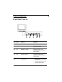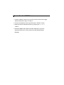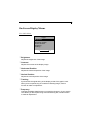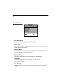
1
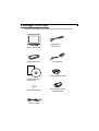
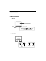
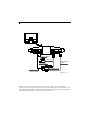
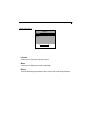
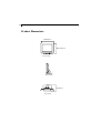
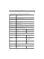
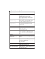
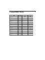
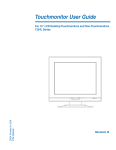
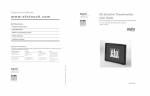
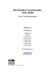
Copyright © 2001 Elo TouchSystems Inc. All Rights Reserved. No part of this publication may be reproduced, transmitted, transcribed, stored in a retrieval system, or translated into any language or computer language, in any form or by any means, including, but not limited to, electronic, magnetic, optical, chemical, manual, or otherwise without prior written permission of Elo TouchSystems. Disclaimer The information in this document is subject to change without notice. Elo TouchSystems makes no representations or warranties with respect to the contents hereof, and specifically disclaims any implied warranties of merchantability or fitness for a particular purpose. Elo TouchSystems reserves the right to revise this publication and to make changes from time to time in the content hereof without obligation of Elo TouchSystems to notify any person of such revisions or changes. Trademark Acknowledgments IntelliTouch, SecureTouch, AccuTouch, Entuitive, and MonitorMouse are trademarks of Elo TouchSystems, Inc. Other product names mentioned herein may be trademarks or registered trademarks of their respective companies. Elo TouchSystems claims no interest in trademarks other than its own. 2 Table of Contents Usage Notice Precautions ................................................................................. 3 Introduction About the Product ....................................................................... 4 Package Overview ...................................................................... 5 Installation Product Overview ........................................................................ 6 Start Your Installation .................................................................. 7 User Controls Front Panel Controls ................................................................... 9 How to Use the OSD Menus ....................................................... 10 On-Screen Display Menus ......................................................... 11 Appendices Troubleshooting ........................................................................... 14 Warning Signal ............................................................................ 15 Product Dimensions ................................................................... 16 Touchmonitor Specifications......................................................... 17 Compatibility Modes ................................................................... 19 Installing the Driver Software ....................................................... 20 Regulatory Information ................................................................. 23 Warranty ....................................................................................... 25 3 Usage Notice Warning- To prevent the risk of fire or shock hazards, do not expose this product to rain or moisture. Warning- Do not open or disassemble the product as this may cause electric shock. Precautions Follow all warnings, precautions and maintenance as recommended in this user’s manual to maximize the life of your unit. Do: q q q q q Turn off the product before cleaning. Use only a dry soft cloth or clean wipe when cleaning the LCD panel surface. Use a soft cloth moistened with mild detergent to clean the display housing. Use only high quality and safety approved AC/DC power adapter. Disconnect the power plug from AC outlet if the product is not used for a long period of time. Don’t: q q q Do not touch the LCD panel surface with sharp or hard objects. Do not use abrasive cleaners, waxes or solvents for your cleaning. Do not operate the product under the following conditions: - Extremely hot, cold or humid environment. - Areas susceptible to excessive dust and dirt. - Near any appliance generating a strong magnetic field. - Place in direct sunlight. 4 Introduction About the Product This product is a 12.1” SVGA TFT color LCD touchmonitor with the following features: q Direct analog RGB input q Active matrix TFT LCD technology q 12.1” diagonal screen size q 16.7 million displayable colors q SVGA 800 x 600 addressable pixels q Auto-adjustment q Full screen re-scaling capability q 31 ~ 54kHz horizontal scan q 56 ~ 85Hz high refresh rate q Multilingual OSD user controls q VESA DPMS power saving q Serial touch interface (RS232 cable) q Built-in speakers q Patented touch technology of Elo TouchSystems. For full product specifications refer to Touchmonitor Specifications, page 16. Package Overview 5 Check that the following 10 items are present and in good condition: LCD Touchmonitor VGA Signal Cable US/Canada Power Cord Power Adapter Manual CD Software European power cable User’s Guide and software CD Mac Video Adapter Audio-In Cable RS-232 Touchscreen Interface Cable 6 Installation Product Overview u Main Unit LCD Touchmonitor User Controls Stand MENU SELECT u Rear View Power Switch Audio In Ear Phone Power DC-In Display Input RS-232 Touch Interface 7 Start Your Installation u Connecting the Touchmonitor (Figure 7.1) To setup this touchmonitor, please refer to the following figure and procedures. 1. Be sure all equipment is off. 2. Connect the VGA signal cable from display input connector to the 15-pin connector of your host computer and tighten the screws. 3. Connect the female end of the touchscreen cable to the serial port on the back of your PC, and the male end of the cable to your touchmonitor. 4. Connect the DC power cord to the power connector; plug one end of the AC power cord into the power adapter, and then the other end into an electrical outlet. 5. Connect the Audio-In cable from audio input port of your touchmonitor to the Audio-out port of your computer. If you need to use earphone, connect your earphone cable to the earphone port of your display. 6. Turn on both your computer and touchmonitor. u Tilt Grasp both sides of the monitor screen with your hands and adjust the tilt as desired. u Install Driver Software Please refer to page 20 for driver software instructions. 8 Power Adapter Power Cord RS-232 Touch Cable Mac Adapter VGA Signal Cable Audio-In Cable (Figure 7.1) Notice: To ensure the LCD display works well with your computer, please configure the display mode of your graphic card to less than or equal to 800 x 600 resolution. Make sure the timing of the display mode is compatible with the LCD display. We have listed the Compatibility Modes of this LCD display in the appendices for your reference. User Controls 9 Front Panel Controls MENU SELECT No. / Icon Control Function MENU Menu button Displays the OSD menus SELECT Select Selects the adjustment items from OSD menus. 3 Decrease / Select Decreases value of the adjustment items or selects the functions. 4 Increase / Select Increases value of the adjustment items or selects the functions. Power LED 1. Green indicates the display is turned on. 2. Amber indicates the display in power-saving mode. 10 How to Use the OSD Menus 1. Press the “MENU” button to pop up the on-screen menu and to toggle between Main Menu Page 1 to Page 3. 2. Choose the adjustment items by pressing the “ SELECT” button. 3. Adjust the value of adjustment items by pressing the “ 3 ” & “ 4 ” buttons. 4. Press the “ MENU” button again to turn off the OSD menu. If you don’t operate the OSD menu in a pre-set time, the OSD will automatically disappear. 11 On-Screen Display Menus First OSD Menu: Main Menu Page 1 Brightness Contrast Horizontal Position Vertical Position Frequency Tracking -3 4+ 4 Brightness Adjusts the brightness of the image. 4 Contrast Adjusts the contrast of the display image. 4 Horizontal Position Adjusts the horizontal position of the image. 4 Vertical Position Adjusts the vertical position of the image. 4 Tracking Synchronizes the signal timing of the display to that of the graphic card. When you are experiencing an unstable or flickering image, use this function to make an adjustment. 4Frequency Changes the display data frequency to match the frequency of your graphic card. When you are experiencing a vertical flickering bar, use this function to make an adjustment. 12 Second OSD Menu: Main Menu Page 2 Auto-Adjustment Re-Scaling Display Mode OSD Off-Time Language Text-Graphic NO Yes 4Auto-Adjustment Choose this function to obtain an optimum image. 4Re-Scaling If the input resolution is less than 800 x 600, you can select this function to obtain the full screen image. 4Display Mode Select this function to demonstrate the display resolution, vertical refresh, and horizontal scan of the current mode. 4OSD Off-Time Adjusts the time period in which the OSD menu will disappear. 4Language Choose the language you need; English, French, German, Spanish and Japanese. 4Text-Graphic Toggles between VGA text mode (mode M03H) and graphic mode (mode M13H). 13 Third OSD Menu: Main Menu Page 3 Volume Mute Reset -3 4+ 4 Volume Allows you to control the volume of sound, 4 Mute Allows you to disable the sound immediately. 4 Reset Returns the display parameters of the current mode to the factory defaults. 14 Appendices Troubleshooting If you are experiencing trouble with the LCD display, refer to the following. If the problem persists, please contact your local dealer or our service center. Please refer to the back cover of this manual for the phone number of the Elo TouchSystems office nearest you. Problem: No image appears on screen. 4 Check that all the I/O and power connectors are correctly and well connected as described in the “ Installation ” section. 4 Make sure the pins of the connectors are not crooked or broken. Problem: Partial image or incorrectly displayed image. 4 Check to see if the resolution of your computer is higher than that of the LCD display. 4 Reconfigure the resolution of your computer to less than or equal to 800 x 600. Problem: Image has vertical flickering line bars. 4 Use “ Frequency ” to make an adjustment. 4 Check and reconfigure the display mode of the vertical refresh rate of your graphic card to make it compatible with the LCD display. Problem: Image is unstable and flickering 4 Use “ Tracking ” to make an adjustment. Problem: Image is scrolling 4 Make sure the VGA signal cable (or adapter) is well connected. 4 Check and reconfigure the display mode of the vertical refresh rate of your graphic card to make it compatible with the LCD display. Problem: Touch doesn’t work 4 Make sure the touchscreen cable is securely attached at both ends. 15 Warning Signal Sometimes you will see warning messages from the LCD screen. This means that the LCD display cannot receive the signal from the computer graphic card. There are three situations where this may happen. Please check the connected cables or contact your local dealer for more information. 4No Signal This message means that the LCD display has been powered on but it cannot receive any signal from the computer graphic card. Check all the power switches, power cables, and VGA signal cable. 4Going to Sleep This message means that the LCD display is in power saving mode. In addition, the LCD display will go to the sleep mode when experiencing a sudden signal disconnecting problem. 4Unsupport Mode This message means that the signal of the computer graphic card is not compatible with the LCD display. When the signal is not included in the compatibility mode we have listed in the Appendices of this manual, the LCD display will show this message. 16 Product Dimensions 340mm/13.4” 286.7mm/11.3” Front View Side View 170mm/6.7” Top View Touchmonitor Specifications 17 12” LCD Touchmonitor (ET12-XXWC-1) Specifications Display Type Active matrix, thin film transistor (TFT), liquid crystal display Size 12- inch diagonal 246 x 185 mm useful screen area N ative Resolution 800 x 600 Touchscreen AccuTouch, anti- glare Colors 16 million with dithering Display Brightness AccuTouch: 188 cd/m† typical Back- light Lamp Life 30,000 hours at full brightness typical Viewing Angle H or izont a l Ve r t ica l Contrast Ratio 100:1 typical +/- 30 or 60 degrees total +/10/- 20 or 30 degrees total Display Response Time 50 ms rise, 50 ms delay typical Environmental Mechanical O pe r a t ing Te mp St or a ge Te mp H umidit y Weight Size Electrical I nput Vide o I nput Powe r I nput Speakers 8 ohms, 1 watt per speaker Agencies Sa fe t y & EM C 10 C to 40 C - 20 C to +60 C 80% non- condensing actual 10 lbs. (5 kg) shipping 17 lbs. (8.5 kg) approx. weight. See drawings on page 15. VGA/SVGA/XGA analog video 100- 240 VAC, 50/60 Hz. Universal UL, cUL and TUV FCC, CE, C- Tick, VCCI 18 AccuTouch Touchmonitor Specifications M e cha nica l Construction Top: Polyester with outside hard- surface coating with clear or antiglare finish. Inside: Transparent conductive coating. Bottom: Glass substrate with uniform resistive coating. Top and bottom layers separated by Elo- patented separator dots. Positional Accuracy Standard deviation of error is less than 0.080 in. (2.03 mm). This equates to less than – 1%. Touchpoint Density More than 100,000 touchpoints/in† (15,500 touchpoints/cm†). Touch Activation Force Typically less than 4 ounces (113 grams). Surface Durability Meets Taber Abrasion Test (ASTM D1044), CS- 10F wheel, 500 g. Meets pencil hardness 3H. Expected Life Performance AccuTouch technology has been operationally tested to greater than 35 million touches in one location without failure, using a stylus similar to a finger. O pt ica l Light Transmission (per ASTM D1003 Typically 75% at 550- nm wavelength (visible light spectrum). Visual Resolution All measurements made using USAF 1951 Resolution Chart, under 30 X magnification, with test unit located approximately 1.5 in. (38 mm) from surface of resolution chart. Clear surface: N /A Antiglare surface: 6:1 minimum. Haze (per ASTM D1003 Clear surface: Less than 1.5%. Antiglare surface: Less than 15%. Gloss (per ASTM D2457) Clear surface: N /A Antiglare surface: 90 – 20 gloss units tested on a hard- coated front surface. 19 Compatibility Modes Mode Resolution V. Frequency (Hz) H. Frequency (kHz) IBM VGA 640 x 350 70 31.5 IBM VGA 640 x 400 70 31.5 IBM VGA 640 x 480 60 31.5 IBM VGA 720 x 400 70 31.5 VESA VGA 640 x 480 72 37.9 VESA VGA 640 x 480 75 37.5 VESA VGA 640 x 480 85 43.3 VESA SVGA 800 x 600 56 35.2 VESA SVGA 800 x 600 60 37.9 VESA SVGA 800 x 600 72 48.1 VESA SVGA 800 x 600 75 46.9 VESA SVGA 800 x 600 85 53.7 Apple Mac LC 640 x 480 67 34.9 Apple Mac II 640 x 480 67 35.0 20 Installing the Driver Software Elo TouchSystems provides driver software that allows your touchmonitor to work with your computer. Drivers are located on the enclosed CD-ROM for the following operating systems: Windows 2000 Windows Me Windows 98 Windows 95 Windows NT 4.0 Additional drivers and driver information for other operating systems (including MS DOS, Windows 3.x, OS/2, Macintosh and Linux) are available on the Elo TouchSystems web site at www.elotouch.com. Your Elo touchmonitor is plug-and-play compliant. Information on the video capabilities of your touchmonitor is sent to your video display adapter when Windows starts. If Windows detects your touchmonitor, follow the instructions on the screen to install a generic plug-and-play monitor. Installing the Touch Driver for Windows 2000, Me, 95/98 and NT 4.0 Refer to the appropriate following section for driver installation instructions. Note: For Windows 2000 and NT 4.0 you must have administrator access rights to install the driver. 1.Insert the Elo CD-ROM in your computer’s CD-ROM drive. If the AutoStart feature for your CD-ROM drive is active, the system automatically detects the CD and starts the setup program. 2. Follow the directions on the screen to complete the driver setup for your version of Windows. If the AutoStart feature is not active: 1. Click Start > Run. 2. Click the Browse button to locate the touch.exe program on the CD-ROM. 3. Click Open, then OK to run touch.exe. 4. Follow the directions on the screen to complete the driver setup for your version of Windows. Installing the Touch Driver for MS-DOS and Windows 3.1 You must have a DOS mouse driver (MOUSE.COM) installed for your mouse if you wish to continue using your mouse along with your touchmonitor in DOS. To install Windows 3.x and MS-DOS from Windows 95/98, follow the directions below: 1. Insert the Elo CD-ROM in your computer’s CD-ROM drive. 2. From DOS, type d:\EloDW to change to the correct directory on the CD-ROM (your CD-ROM drive may be mapped to a different drive letter). 3. Type install and press Enter to start the installation. 4. Align the touchscreen. Refer to Chapter 2 of the Elo DOS and Windows Driver Guide as necessary for additional installation information. The driver guide can be found on Elo’s web site at www.elotouch.com. 21 22 To run the INSTALL program: 1. Type INSTALL at the DOS prompt in the directory containing the driver install files. 2. INSTALL asks you to select the software to install. Then choose d:\EloDW from the displayed list. 3. INSTALL also asks you for the paths to use during installation, or you may use its defaults. INSTALL creates directories as necessary, and warns you if they exist. If you are updating your software, you may wish to specify the paths containing the earlier versions, and overwrite the obsolete files. All executable programs are upward compatible. For a list of differences from each previous version of the drivers, be sure to select “Differences from Previous Versions” during the installation process. INSTALL updates your AUTOEXEC.BAT file with the drivers you select. INSTALL makes a copy of your original AUTOEXEC.BAT called AUTOEXEC.OLD. If you already have Elo driver commands in your AUTOEXEC.BAT file, they will be commented out. When INSTALL is finished, it leaves a file called GO.BAT in the subdirectory you specified. GO loads the touchscreen driver, runs the calibration program ELOCALIB, and gives you some final instructions. If you are using Windows 3.1, you will also calibrate the touchscreen within Windows 3.1 with the Touchscreen Control Panel. Regulatory Information I. Electrical Safety Information: A) Compliance is required with respect to the voltage, frequency, and current requirements indicated on the manufacturer’s label. Connection to a different power source than those specified herein will likely result in improper operation, damage to the equipment or pose a fire hazard if the limitations are not followed. B) There are no operator serviceable parts inside this equipment. There are hazardous voltages generated by this equipment which constitute a safety hazard. Service should be provided only by a qualified service technician. C) This equipment is provided with a detachable power cord which has an integral safety ground wire and 3-prong connector intended for connection to a grounded safety outlet. 1) Do not substitute the cord with other than the provided approved type. Under no circumstances use an adapter plug to connect to a 2-wire outlet as this will defeat the continuity of the grounding wire. 2) The equipment requires the use of the ground wire as a part of the safety certification, modification or misuse can provide a shock hazard that can result in serious injury or death. 3) Contact a qualified electrician or the manufacturer if there are questions about the installation prior to connecting the equipment to mains power. II. Emissions and Immunity Information A) Notice to Users in the United States: This equipment has been tested and found to comply with the limits for a Class B digital device, pursuant to Part 15 of FCC Rules. These limits are designed to provide reasonable protection against harmful interference in a residential installation. This equipment generates, uses, and can radiate radio frequency energy, and if not installed and used in accordance with the instructions, may cause harmful interference to radio communications. B) Notice to Users in Canada: This equipment complies with the Class B limits for radio noise emissions from digital apparatus as established by the Radio Interference Regulations of Industrie Canada. C) Notice to Users in the European Union: Use only the provided power cords and interconnecting cabling provided with the equipment. Substitution of provided cords and cabling may compromise electrical safety or CE Mark Certification for emissions or immunity as required by the following standards: This Information Technology Equipment (ITE) is required to have a CE Mark on the manufacturer’s label which means that the equipment has been tested to the following Directives and Standards: This equipment has been tested to the requirements for the CE Mark as required by EMC Directive 89/336/EEC indicated in European Standard EN 55 022 Class B and the Low Voltage Directive 73/23/EEC as indicated in European Standard EN 60 950. D) General Information to all Users: This equipment generates, uses and can radiate radio frequency energy. If not installed and used according to this manual the equipment may cause interference with radio and television communications. There is, however, no guarantee that interference will not occur in any particular installation due to site-specific factors. 23 24 1) In order to meet emission and immunity requirements, the user must observe the following: a) Use only the provided I/O cables to connect this digital device with any computer. b) To ensure compliance, use only the provided manufacturer’s approved line cord. c) The user is cautioned that changes or modifications to the equipment not expressly approved by the party responsible for compliance could void the user’s authority to operate the equipment. 2) If this equipment appears to cause interference with radio or television reception, or any other device: a) Verify as an emission source by turning the equipment off and on. b) If you determine that this equipment is causing the interference, try to correct the interference by using one or more of the following measures: i) Move the digital device away from the affected receiver. ii) Reposition (turn) the digital device with respect to the affected receiver. iii) Reorient the affected receiver’s antenna. iv) Plug the digital device into a different AC outlet so the digital device and the receiver are on different branch circuits. v) Disconnect and remove any I/O cables that the digital device does not use. (Unterminated I/O cables are a potential source of high RF emission levels.) vi) Plug the digital device into only a grounded outlet receptacle. Do not use AC adapter plugs. (Removing or cutting the line cord ground may increase RF emission levels and may also present a lethal shock hazard to the user.) If you need additional help, consult your dealer, manufacturer, or an experienced radio or television technician. Warranty Except as otherwise stated herein or in an order acknowledgment delivered to Buyer, Seller warrants to Buyer that the Product shall be free of defects in materials and workmanship. The warranty for the touchmonitors and components of the product are: 3 years monitor, 10 years IntelliTouch screen, 5 years AccuTouch screen, 5 years Controller. Seller makes no warranty regarding the model life of components. Seller’s suppliers may at any time and from time to time make changes in the components delivered as Products or components. Buyer shall notify Seller in writing promptly (and in no case later than thirty (30) days after discovery) of the failure of any Product to conform to the warranty set forth above; shall describe in commercially reasonable detail in such notice the symptoms associated with such failure; and shall provide to Seller the opportunity to inspect such Products as installed, if possible. The notice must be received by Seller during the Warranty Period for such product, unless otherwise directed in writing by the Seller. Within thirty (30) days after submitting such notice, Buyer shall package the allegedly defective Product in its original shipping carton(s) or a functional equivalent and shall ship to Seller at Buyer’s expense and risk. Within a reasonable time after receipt of the allegedly defective Product and verification by Seller that the Product fails to meet the warranty set forth above, Seller shall correct such failure by, at Seller’s options, either (i) modifying or repairing the Product or (ii) replacing the Product. Such modification, repair, or replacement and the return shipment of the Product with minimum insurance to Buyer shall be at Seller’s expense. Buyer shall bear the risk of loss or damage in transit, and may insure the Product. Buyer shall reimburse Seller for transportation cost incurred for Product returned but not found by Seller to be defective. Modification or repair, of Products may, at Seller’s option, take place either at Seller’s facilities or at Buyer’s premises. If Seller is unable to modify, repair, or replace a Product to conform to the warranty set forth above, then Seller shall, at Seller’s option, either refund to Buyer or credit to Buyer’s account the purchase price of the Product less depreciation calculated on a straight-line basis over Seller’s stated Warranty Period. THESE REMEDIES SHALL BE THE BUYER’S EXCLUSIVE REMEDIES FOR BREACH OF WARRANTY. EXCEPT FOR THE EXPRESS WARRANTY SET FORTH ABOVE, SELLER GRANTS NO OTHER WARRANTIES, EXPRESS OR IMPLIED BY STATUTE OR OTHERWISE, REGARDING THE PRODUCTS, THEIR FITNESS FOR ANY PURPOSE, THEIR QUALITY, THEIR MERCHANTABILITY, THEIR NONINFRINGEMENT, OR OTHERWISE. NO EMPLOYEE OF SELLER OR ANY OTHER PARTY IS AUTHORIZED TO MAKE ANY WARRANTY FOR THE GOODS OTHER THAN THE WARRANTY SET FORTH HEREIN. 25 26 SELLER’S LIABILITY UNDER THE WARRANTY SHALL BE LIMITED TO A REFUND OF THE PURCHASE PRICE OF THE PRODUCT. IN NO EVENT SHALL SELLER BE LIABLE FOR THE COST OF PROCUREMENT OR INSTALLATION OF SUBSTITUTE GOODS BY BUYER OR FOR ANY SPECIAL, CONSEQUENTIAL, INDIRECT, OR INCIDENTAL DAMAGES. Buyer assumes the risk and agrees to indemnify Seller against and hold Seller harmless from all liability relating to (i) assessing the suitability for Buyer’s intended use of the Products and of any system design or drawing and (ii) determining the compliance of Buyer’s use of the Products with applicable laws, regulations, codes, and standards. Buyer retains and accepts full responsibility for all warranty and other claims relating to or arising from Buyer’s products, which include or incorporate Products or components manufactured or supplied by Seller. Buyer is solely responsible for any and all representations and warranties regarding the Products made or authorized by Buyer. Buyer will indemnify Seller and hold Seller harmless from any liability, claims, loss, cost, or expenses (including reasonable attorney’s fees) attributable to Buyer’s products or representations or warranties concerning same.