1
PRO VLA
PROFESSIONAL TWO CHANNEL VACTROL/TUBE
LEVELING AMPLIFIER
USER’S GUIDE
TABLE OF CONTENTS
Introduction
Registration
Features
Overview
Setting Up
Unpacking
AC Power Hookup
Audio Connections
Installation
Safety Precautions
Powering Up
Front Panel Controls and Indicators
Power
Threshold Control
Ratio Control
Output Level Control
VU Meter Input/Output Switch
Attack Time Switch
Release Time Switch
Bypass Switch
Stereo Link/Dual Mode Switch
Gain Reduction Meter
VU Level Meter
Rear Panel Connections
Input
Output
Applications
Tube Replacement
Warranty Information
Service Information
PRO VLA Specifications
On-line Information
2
2
3
4
5
5
5
5
5
6
6
6
6
7
7
8
8
8
8
9
9
10
10
10
11
11
11
12
12
13
14
14
212-5004-101
1
Introduction
Thank you for purchasing Applied Research and Technology’s
PRO VLA. Offering a superb level of sound quality, the PRO VLA
has a unique design which will enhance the sonic textures of
your audio system for years to come.
Registration
If you haven’t done so already, please take the time to fill out
the User Registration Card for your purchase. Having you in our
data base allows us to keep you informed of updates, application notes, and new product introductions. It only takes a
moment and will ensure you are constantly up to date with
your purchase.
Fill in the following for your future reference:
Date of purchase: ___________________
Purchased From: ____________________
Serial Number: 212-________
Features
The PRO VLA is one of the finest audio compressors available.
Developed in partnership with studio and live sound engineers,
the PRO VLA possesses a “sound” that is not available from any
other compressor on the market - at any price! A member of the
A R T Reference Series, the PRO VLA was designed and constructed with the absolute best components, assuring a lifetime
of quiet, reliable performance. The PRO VLA offers:
- Two channel Opto-isolator (Vactrol)/tube-based Leveling
Amplifier
- Stereo linking of channels
- Hand selected 12AX7 Tubes
- Vactrol - Optical electronic isolators
- Non-VCA design = transparent, classic sound
- VU metering of input and output levels
- XLR balanced inputs and outputs
- 1/4” TRS active balanced inputs and outputs
- Variable threshold ratio
- Auto and Fast attack and release settings
- Variable Threshold rotary controls
- Variable Output level rotary controls
- 10 segment Gain Reduction LED Array
- 10Hz to 20kHz Frequency Response (+/-0.5dB)
- >100dB Dynamic Range
- Extremely low noise (-99dBm ‘A’ weighted)
- Internal power supply
- 5-year parts and labor warranty
- Designed and manufactured in the USA
The PRO VLA is member of A R T’s Reference Series of professional signal processing products.
2
3
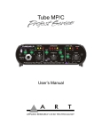
OVERVIEW
Design
The PRO VLA (Vactrol-based Leveling Amplifier) is a multi-purpose tool for audio engineering and recording. Enclosed in a
2U (3.5” high) rack-mountable chassis are two independent
channels of analog compression designed to work seamlessly
with any recording, sound-reinforcement, or electronic instrument setup.
A R T’s PRO VLA circuitry is a hybrid design utilizing the latest
and most advanced solid state and tube technology. Using a
transformerless design throughout, the PRO VLA maintains
exceptional signal integrity and extremely low noise. Its VCAless design utilizes optical electronics (Vactrol) coupled with a
12AX7 vacuum tube gain stage for superior musical performance.
The PRO VLA is a soft knee leveling amplifier by design.
Although it is capable of providing a thoughougly “squashed”
signal, the PRO VLA was designed to excel in areas where transparent, expressively musical dynamics control is desired.
Application
Compression is used to alter the dynamic range of a signal. In
recording and live sound situations, compression and limiting
is necessary to manage sounds with wide dynamic ranges.
Dynamic Range is measured as the difference between the loudest and softest level of a signal. (i.e. from a scream to a whisper). Once a signal rises above or falls below the set threshold
(selectable signal level), the compressor automatically changes
its gain to raise or lower the overall signal level. Think of this as
manually moving a fader up and down to try to keep a signal at
a consistent level.
Limiting can be described as a “ceiling”. When using a limiter,
once the signal level reaches the threshold, it is unable to go
any louder - it is limited to a desired level.
sion without sounding like you’re squashing the daylights out
of the signal. Unlike typical compressors which use VCA’s to
control level detection, the PRO VLA is very musical. The nature
of its operation is much like the way your eye adjusts to light.
Just as your eye transparently adjusts to changes in light, the
PRO VLA adjusts to changes in signal level.
SETTING UP
Unpacking
Your PRO VLA was packed with care at the factory. The shipping carton was designed to protect it during initial shipment.
Please retain this carton for use in transporting the PRO VLA
when it is not installed in a rack, or in the unlikely event that
you need to return your PRO VLA for servicing.
The shipping carton should contain:
- The PRO VLA
- The owner’s manual
- User Registration Card
AC Power Hookup
The PRO VLA has an internal power supply designed to operate
at 100 to 125VAC, 50 to 60Hz. Units manufactured for use outside of the United States of America have been modified to
comply with the required electrical specifications. Under no circumstances should the power cable be altered. If the cable
becomes cut or damaged,
discontinue its use and have it replaced before operating the
Pro VLA.
Audio Connections
Audio connections to and from the PRO VLA are balanced XLR
(Pin 2 Hot (+), Pin 3 Cold (-), Pin 1 Ground) and active balanced 1/4” TRS (Tip = Hot (+), Ring = Cold (-), Sleeve =
Ground). Unbalanced 1/4” cables may be used with no damage
to the PRO VLA. We recommend using only high-quality cables
equipped with the appropriate connectors.
In addition to making signal levels more manageable, it is common practice to apply compression or limiting to a signal to
make it louder or more “in-your-face”. The benefit of using the
PRO VLA for these applications is in its design. By utilizing
opto-electronics, the PRO VLA allows you to add more compres-
Installation
The PRO VLA may be employed in a number of setups including:
- Between a microphone preamplifier and a mixer, digital multi-
4
5
track recorder, DAT machine, hard disk recorder, or analog
recorder.
- In a mixer’s channel insert points.
- Between a microphone preamp and signal processors.
- Between preamplified electronic musical instruments (synthesizers, guitars, bass, samplers, acoustic instruments with pickups) and other line level equipment.
Note: the PRO VLA should be securely mounted in a standard
19” rack.
SAFETY PRECAUTIONS
Warning: To avoid the risk of shock or fire, do not expose this
unit to moisture. Do not remove metal panels from chassis
parts. Removing the chassis from its cabinet parts exposes dangerous high voltages. There are no user-serviceable parts inside.
Hazardous voltages are present inside the chassis. Refer all servicing to qualified personnel.
Caution: If your power cord becomes damaged and must be
replaced, always replace it with the proper type (3 prong).
POWERING UP
When the power switch is turned on, the VU meters will light.
LEDs will light if its associated switch is in its “in” position.
Power on the PRO VLA before any monitoring levels or power
amps are turned on.
Like all tube-based equipment, the PRO VLA needs to warm up
to operating temperature. The 12AX7 tubes will reach operating
temperature within one to three minutes. During this warm up
period you may experience variations due to the THD of the
tubes stabilizing. This is normal and the PRO VLA will provide
consistent results once this warm up period is over.
If the PRO VLA fails to power up when the power switch is
turned on, check to see that its power cord is plugged into an
active outlet. If the unit still fails to operate properly, turn it off
and unplug it. Then consult your dealer or A R T’s Customer
Service department.
6
FRONT PANEL CONTROLS & INDICATORS
Power
The Power switch supplies and removes power from the unit.
The PRO VLA should be powered “on” with all monitor levels
turned down to protect against any “thumping” caused by gain
settings. Likewise, the PRO VLA should be turned “off” after
turning all monitor levels down.
Threshold Control
The Threshold control sets the point at which the PRO VLA will
act on a signal. Turning this control counter-clockwise lowers
the threshold (adding more compression to a signal). Turning
this control clockwise raises the threshold.
Setting the Threshold control is dependent on the input signal.
The output from a guitar might be -20dB to -10dB, where the
level from an insert on a console might be -10dB to +15dB.
The easiest way to set the threshold control is to start with the
control fully clockwise. Slowly turn the control counter-clockwise (lowering threshold) until you see the yellow Threshold
LED light. Now adjust the control (either lower or higher) until
you have the amount of compression you desire. Use the Gain
Reduction meter as a visual guide to the amount of compression applied.
Ratio Control
The Ratio Control selects the “amount” of compression applied
to the input signal once that signal reaches or exceeds the
threshold. This compression amount is expressed as a ratio of
input to output. For example if a 4:1 compression ratio is chosen, for every 4dB over the threshold the input signal rises, the
output level only rises by 1dB. In this case if the input signal
was 12dB over the threshold, the output level would rise by
only 3dB.
Generally compression ratios of 10:1 and greater are considered limiting.
The range of the Ratio control is 2:1 to 10:1. The PRO VLA may
be used as either a compressor or limiter.
7
Output Control
The Output control sets the output gain of the PRO VLA. When
the control is fully counterclockwise, the output level of the
PRO VLA is attenuated by -83dB. Turning the control clockwise
adds gain (sometimes called “make-up” gain). Since levels can
be decreased when compression is applied, the PRO VLA has
the ability to apply gain to bring the processed signal back up
to unity (same as input level). To properly set the output level,
adjust the Output Control while switching between Active and
Bypass. When these two levels are equal in volume, the output
control is set properly.
VU Meter - Input/Output Switch
The VU Meter Input/Output Switch toggles the VU meter
between displaying either input or output signal levels. The
Input setting is the signal entering into the PRO VLA. The
Output setting is the signal (post-process) leaving the PRO VLA.
In stereo applications, place one switch in the Input position
and one switch in the Output position. This enables you to see
both levels at a single glance of the meters.
Note: The Zero (“0”) level of the VU meter is calibrated at
+4dBm when using the XLR connectors into a 600 Ohm load or - when using the 1/4” outputs into a high impedance load.
Attack Time Switch
The position of the Attack Time switch selects the attack characteristics for the channel of the PRO VLA. Attack Time refers to
how quickly compression is added after the input signal rises
above the Threshold. Since different signals have different
attack characteristics, it is important for a compressor to have
different settings which allow the action of the compressor to
sound more natural. The “out” position is the “Auto” setting.
The Auto setting is a program dependant attack time with 20ms
being the slowest the PRO VLA will take to achieve 20dB of
compression. In other words, the Attack Time circuitry in the
PRO VLA is designed to “adapt” to the signal characteristics of
the signal you are processing. The “in” position is the “Fast”
setting. This setting has a fixed attack time of 2ms. The Fast setting is ideal for punchy, repetitive signals.
acteristics for the channel of the PRO VLA. Release Time refers
to how quickly the channel returns to unity gain (no compression) after the input signal falls below the Threshold. Again,
since different signals have different decay characteristics, it is
important for a compressor to have different settings which
allow the action of the compressor to sound more natural. The
“out” position is the “Auto” setting. The Auto setting is an automatically adjusting (sometimes called “program dependent”)
release time with a range of 100ms to 3 seconds. The “in” position is the “Fast” setting. This setting has a fixed release time of
300ms. The Fast setting is ideal for punchy, repetitive signals.
Use the “auto” setting when the signal has varying characteristics (long decaying notes alternating with quick notes, mix
material, etc.).
Bypass Switch
A Bypass switch is included on each channel of the PRO VLA to
enable you to remove the unit from your signal chain. When set
to its “in” position, the channel of the PRO VLA allows signal to
pass from the input jacks to the output jacks with no processing. The LED will illuminate to inform you the channel is
bypassed. In its “out” position, the PRO VLA is active and the
input signal is processed. Use the Bypass switch when setting
the PRO VLA’s Output Level to achieve unity (no boost or cut)
gain. Unity gain is achieved when the active level is the same as
the bypassed level.
Release Time Switch
The position of the Release Time switch selects the release char-
Stereo Link/ Dual Mode Switch
The PRO VLA may be used as two independent channels of
compression/limiting or as a stereo processor. When the Stereo
Link/Dual Mode switch is in its “out” position, the PRO VLA
operates as two independent channels. With the switch in its
“in” position, the PRO VLA is a stereo unit. In this Linked mode
the Threshold, Ratio, Attack and Release controls of channel #1
are used to control both channels of the PRO VLA. You’ll notice
these controls on channel #2 are inactive when the Stereo
Link/Dual Mode switch is “in”. This design is common among
professional compressors. It ensures that each channel of the
stereo input signal is processed identically to prevent any shifting or distortion of the stereo image. The Output controls
remain independent in the Link Mode to allow for level matching. The LED will light when the switch is in the “in” (linked)
position.
8
9
equipment.
Gain Reduction Meter
Each channel of the PRO VLA has a ten segment LED gain
reduction meter. These meters provide a visual indication of
how much compression is taking place. The right-most LED in
these meters is the Threshold LED. The Threshold LED will
light when the input signal reaches the level set by the
Threshold control. The range of the meter is -1dB to -30dB.
VU Level Meter
Each channel of the PRO VLA has a backlit VU meter showing
either the input or output level (switch dependant). The zero
(“0”) level is calibrated to +4dBm (with a 600 ohm load on the
XLR output or a high impedance load on the 1/4” output). Use
the VU meter to view input (unprocessed) and output
(processed) levels. The meters are active when the PRO VLA is
in bypass.
Do not use both inputs on a channel at the same time.
Outputs
The outputs of the PRO VLA are active balanced. You may use
these in unbalanced configurations without harm to the output
circuitry. Use the unbalanced 1/4” jack for sending your signal
to amps, processors or other unbalanced configurations. Use
the XLR output to send signals to equipment which accepts XLR
connections. Both outputs may be used at the same time.
**Note: If you experience a grounding hum when using both
output connectors simultaneously, a ground loop may be the
problem. To remedy this problem, disconnect (lift) the ground
wire (pin 1) from the XLR cable plugged into the PRO VLA’s
output. This interrupts the ground path and therefore breaks
the loop.
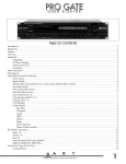
REAR PANEL CONNECTIONS
APPLICATIONS
It’s easy to interface the PRO VLA with other equipment.
Balanced XLR and balanced 1/4” phone, input and output connectors are located on the rear panel.
The PRO VLA’s XLR connectors follow the AES standard of: Pin
1 = Ground, Pin 2 = Hot (+), Pin 3 = Cold (-). The balanced
1/4” phone jacks are typical TRS connections: Tip - Hot (+),
Ring - Cold (-),
Sleeve - Ground.
Input
The PRO VLA provides both an XLR and 1/4” input jack. Both
jacks are balanced. The 1/4” jack can be used with unbalanced
signals by simply plugging in an unbalanced cable. The inputs
are designed for use with line level signals ranging from 30dBm to +20dBm. While it is possible to plug an instrument
directly into the PRO VLA, it is desirable to run the instrument
into a preamp before the signal runs into the PRO VLA. This
will provide a stronger signal and will keep noise to a minimum. Microphones must be run into a microphone preamplifier (like A R T’s PRO MPA) before being run into the PRO VLA.
Use the XLR input for use with equipment that provides an XLR
output. Use the 1/4” input jack for balanced or unbalanced 1/4”
10
Compressor/ limiter
The main application of the PRO VLA is to control the dynamic
range of a signal level. Plug a line level (post preamplifier or
other gain stage) source into either input and set the threshold
and output controls to provide the desired amount of compression to the input signal.
Stereo mix and mastering
Because of its low noise and excellent tonal qualities, the PRO
VLA is ideal for running mixes through before recording to
DAT, hard disk or analog recording devices. Used as a mastering device, the PRO VLA is capable of adding warmth and
impact to the overall signal level. The PRO VLA is ideal for live
use as well.
Vocal and instrument levelling
The musical nature of the PRO VLA makes it ideal for use on a
wide range of instruments and vocals. Place the PRO VLA into a
channel insert, after a preamplifier, or from a direct output of a
channel of a mixer. Adjust the controls of the PRO VLA to
achieve the desired amount of compression.
11
Tube Replacement
The two 12AX7A tubes in your PRO VLA have been specially
selected and sorted to specific operating tolerances. The origianl tubes should provide years of trouble-free performance. In
the event they need to be replaced, we reccommend replacing
them with tubes available from
A R T. We cannot guarantee consistent performance from “offthe-shelf” replacements.
WARRANTY AND SERVICE INFORMATION
Limited Warranty
Warranty service for this unit will be provided by Applied
Research & Technology, Inc. in accordance with the following
warrant statement.
Applied Research & Technology, Inc. (A R T) warrants to the
original purchaser that this product and the components thereof will be free from defects in workmanship and materials for a
period of five years from the date of purchase. Applied Research
& Technology, Inc. will, without charge, repair or replace, at its
option, defective product or component parts upon prepaid
delivery to the factory service department or authorized service
center, accompanied by proof of purchase date in the form of a
valid sales receipt.
EXCLUSIONS: This warranty does not apply in the event of misuse or abuse of the product or as a result of unauthorized alterations or repairs. This warranty is void if the serial number is
altered, defaced, or removed.
A R T reserves the right to make changes in design or make
additions to or improvements upon this product without any
obligation to install the same on products previously manufactured.
For units purchased outside the United States, service will be
provided by an authorized distributor of Applied Research and
Technology, Inc.
SERVICE
The following information is provided in the unlikely event that
your unit requires service.
1) Be sure that the unit is the cause of the problem. Check to
make sure the unit has power supplied, all cables are connected correctly, and the cables themselves are in working condition.
2) If you find the unit to be at fault, write down a complete
description of the problem, including how and when the problem occurs, and a description of your complete setup before
calling Customer Service.
3) Call our Customer Service department for a Return
Authorization (RA) number or questions regarding technical
assistance. Customer Service hours are 9:00am to 6:00pm
Eastern Time, Monday through Friday.
4) Pack the unit in its original carton or a reasonable substitute.
The packing box is not recommended for a shipping carton. Put
the packaged unit in another box for shipping. Print the RA
number clearly on the outside of the shipping box. Print your
return shipping address on the outside of the box.
5) Include with your unit: a return shipping address (we cannot
ship to a P.O. Box), a copy of your purchase receipt, a daytime
phone number, and a description of the problem. Keep your
manual!
6) Ship your unit to:
A R T shall not be liable for any consequential damages, including without limitation damages resulting from loss of use. Some
states do not allow limitation of incidental or consequential
damages, so the above limitation or exclusion may not apply to
you. This warranty gives you specific rights and you may also
have other rights which vary from state to state.
APPLIED RESEARCH AND TECHNOLOGY, INC.
215 TREMONT STREET
ROCHESTER, NEW YORK 14608
ATTN: REPAIR DEPARTMENT
RA#_______________________
12
13
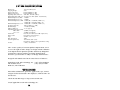
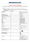
A R T PRO VLA SPECIFICATIONS
Dimensions
Shipping Weight
Input Connections
Output Connections
Input Impedance XLR, 1/4"
Output Impedance XLR, 1/4"
Maximum Input Level, XLR
Maximum Input Level, 1/4"
Maximum Output Level, XLR
19”W X 6.5”D X 3.5"H
9 Lbs
balanced XLR & 1/4" TRS
balanced XLR & 1/4" TRS
20K ohms, 1M ohms (unbal.)
600 ohm, 300 ohms (unbal - 600ohms bal.)
+21dBm
+21dBm
+27dBu (RL = 100Kohms, THD = 5%)
+21dBu (RL = 600ohms, THD = 5%)
Maximum Output Level, 1/4" +21dBu (RL = 100Kohms, THD = 5%)
Frequency Response
10Hz to 20kHz (+/- .5dB)
Dynamic Range
>100dB (20-20kHz)
THD @ 0dBm out:
<0.1% (typical)
Equivalent Input Noise (EIN)
XLR to XLR
-99dBm ('A' weighted)
1/4" to 1/4"
-97dBm ('A' weighted)
Attack Time
Fast 2ms, Slow 15ms (for 20dB compression)
Release Time
Fast-300ms, Slow 100ms-3sec.
Slope
Variable: 2:1 to >10:1
Max. Attenuation
30dB
Power Requirements:
100-125VAC, 25W - (USA)
Internal fuse. Other power requirements configured for
country of destination.
A R T retains a policy of constant product improvement. A R T
reserves the right to make changes in design or make additions
to or improvements upon this product without any obligation
to install the same on products previously manufactured.
Therefore, specifications are subject to change without notice.
Designed and manufactured in the United States of America.
Applied Research and Technology, Inc. (716) 436-2720 Phone
215 Tremont Street
(716) 436-3942 FAX
Rochester, NY 14608 USA
WE’RE ON-LINE!
For Product information, questions, applications, tips, answers
and general discussion with A R T employees, look for A R T on
the Internet..
Check out our Web Page at: http://www.artroch.com
©1996 Applied Research and Technology, Inc.
14