1
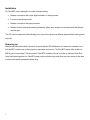
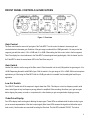
Tube MP/C
User’s Manual
IMPORTANT SAFETY INSTRUCTIONS – READ FIRST
This symbol, wherever it appears,
alerts you to the presence of uninsulated
dangerous voltage inside the enclosure. Voltage
that may be sufficient to constitute a risk of shock.
This symbol, wherever it appears, alerts
you to important operating and maintenance
instructions in the accompanying literature.
Please read manual.
Read instructions:
Retain these safety and operating instructions for future reference. Heed all warnings printed here and on the equipment. Follow the operating
instructions printed in this user guide.
Do not open:
Aside from two vacuum tubes, there are no user serviceable parts inside. Refer any service work to qualified technical personnel only.
Power sources:
Only connect the unit to mains power of the type marked on the rear panel. The power source must provide a good ground connection.
Power cord:
Use the power cord with the mains plug appropriate for your local mains supply as provided with the equipment. If the provided plug does not fit into
your outlet consult your service agent. Route the power cord so that it is not likely to be walked on, stretched or pinched by items placed upon or
against.
Grounding:
Do not defeat the grounding and polarization means of the power cord plug. Do not remove or tamper with the ground connection on the power cord.
Ventilation:
Do not position the unit where the air required for ventilation is impeded. If the unit is to be operated in a rack, case or other furniture, ensure that it is
constructed to allow adequate ventilation.
Moisture:
To reduce the risk of fire or electrical shock do not expose the unit to rain, moisture or use in damp or wet conditions. Do not place a container of
liquid on it, which may spill into any openings.
Heat:
Do not locate the unit in a place close to excessive heat or direct sunlight, as this could be a fire hazard. Locate the unit away from any equipment,
which produces heat such as: power supplies, power amplifiers and heaters.
Environment:
Protect from excessive dirt, dust, heat, and vibration when operating and storing. Avoid tobacco ash, drink spillage and smoke, especially that
associated with smoke machines.
Handling:
To prevent damage to the controls and cosmetics avoid rough handling and excessive vibration. Protect the controls from damage during transit. Use
adequate padding if you need to ship the unit. To avoid injury to yourself or damage to the equipment take care when lifting, moving or carrying the
unit.
Servicing:
Switch off the equipment and unplug the power cord immediately if it is exposed to moisture, spilled liquid, objects fallen into opening, or the power
cord or plug becomes damaged during a lightning storm or if smoke odor or noise is noted. Refer servicing to qualified technical personnel only.
Installation:
Install the unit in accordance with the instructions printed in the user guide.
II
IMPORTANT SAFETY INSTRUCTIONS – READ FIRST .................................. II
INTRODUCTION ............................................................................................. 1
OVERVIEW ..................................................................................................... 2
SETTING UP ................................................................................................... 2
Unpacking .................................................................................................................................... 2
AC Power Hookup ....................................................................................................................... 2
Installation .................................................................................................................................... 3
Powering up ................................................................................................................................. 3
FRONT PANEL CONTROLS & INDICATORS................................................... 4
Gain Control ................................................................................................................................. 4
Gain Switch .................................................................................................................................. 4
Low Cut Switch ............................................................................................................................. 4
Tube Drive Display ....................................................................................................................... 4
Threshold Control ......................................................................................................................... 5
Slope Switch ................................................................................................................................. 5
Speed Switch ................................................................................................................................ 5
Phase Switch ............................................................................................................................... 6
Opto Comp Switch ........................................................................................................................ 6
Gain Reduction Display ................................................................................................................ 6
The Output Level Control .............................................................................................................. 6
Output Level Display..................................................................................................................... 6
REAR PANEL FUNCTIONS ............................................................................. 7
Power ........................................................................................................................................... 7
Input and Output Connections ..................................................................................................... 7
Input ............................................................................................................................................. 7
Balanced Output ........................................................................................................................... 7
Unbalanced Output ....................................................................................................................... 8
Output Switch ............................................................................................................................... 8
Phantom Power Switch ................................................................................................................. 8
APPLICATIONS ............................................................................................. 9
Using the Tube MP/C as a DI ....................................................................................................... 9
Tracking ....................................................................................................................................... 9
Re-Amping ................................................................................................................................... 9
Special Effects ............................................................................................................................ 10
TUBE REPLACEMENT .................................................................................. 10
WARRANTY INFORMATION: ........................................................................ 11
SERVICE: ...................................................................................................... 11
SPECIFICATIONS: ........................................................................................ 12
III
INTRODUCTION
Thank you for purchasing Applied Research and Technology’s Tube MP/C. You’ve undoubtedly noticed that the Tube MP/C
is as cool sounding as it looks. After getting familiar with the Tube MP/C, you’ll realize what a great investment you’ve just
made. The Tube MP/C may be used everywhere! Anywhere you need level adjustments (gain or attenuation), and
anywhere you need compression - you’ll be using the Tube MP/C. Offering a superb level of sound quality, the Tube MP/C
will enhance the sonic textures of your audio system for years to come.
The Tube MP/C is a unique product. It contains two independent award-winning circuit designs - one of the finest tube
microphone preamplifiers available and one of the finest optical tube compressors available. Developed in partnership with
studio and live sound engineers, the Tube MP/C possesses a “sound” that is not available from any other product on the
market - at any price! The Tube MP/C was designed and constructed with the best components, assuring a lifetime of quiet,
reliable performance.
The Tube MP/C offers:
1
•
The award-winning A R T “SOUND”!
•
Tube-based mic/line preamplifier with up to 70 dB of gain
•
Hand-selected 12AX7a tube
•
Optical (VCA-less) compressor circuitry = transparent dynamics control
•
Bypassable compression circuitry
•
1/4” TS unbalanced inputs and outputs
•
XLR balanced inputs and outputs
•
Transformer isolated XLR output
•
Selectable output range for Line/Instrument interface levels
•
LED meters for Tube Warmth, Gain Reduction and Output level
•
+48V phantom power
•
Phase reversal switch
•
Selectable release time settings
•
>90dB dynamic range
•
Custom extruded aluminum chassis
OVERVIEW
The Tube MP/C (PreAmplifier/Compressor) is a multi-purpose tool for audio engineering and recording. Enclosed in a tabletop chassis are two independent circuits featuring a tube-based analog preamplifier and a VCA-less compressor with optical
gain reduction control. Used as a mic/line preamp or as a DI (direct) box, the Tube MP/C is designed to work seamlessly
with any recording, sound-reinforcement, or electronic instrument setup. A R T’s Tube MP/C circuitry is a hybrid design
utilizing the latest, most advanced, solid-state and tube technology. The Tube MP/C maintains exceptional signal integrity
and extremely low noise. A tube based opto-compressor circuit follows the tube preamp. While the preamp is always active,
the compressor may be bypassed. The preamplifier’s active balanced solid-state input provides extremely low noise and
excellent CMRR. The 1/4” input has a high impedance, which prevents the loading of any device connected to it and makes
the Tube MP/C perfect for DI or line level applications. The preamplifier’s second stage 12AX7a tube runs on a regulated
DC voltage providing an additional 20dB of gain. Our design causes the tube to overload before the input or output stage.
This allows you to manipulate the tube gain to meet different sonic requirements. The compression circuit features a VCAless design and utilizes optical electronics (Vactrol) coupled with a 12AX7a vacuum tube gain stage for superior musical
performance. The compressor is soft knee by design. Although it is capable of providing a thoroughly “squashed” signal in
"Limit" mode, it was designed to excel in areas where transparent and musical dynamics control is desired. The beauty of
the optical/tube design is its ability to apply heavy amounts of compression without pumping and breathing like VCA-based
compressors. In many cases you will hear the results of the compression without hearing the compressor.
SETTING UP
Unpacking
Your Tube MP/C was packed with care at the factory. The shipping carton was designed to protect it during initial shipment.
Please retain this carton for use in transporting the Tube MP/C, or in the unlikely event that you need to return your Tube
MP/C for servicing.
AC Power Hookup
The Tube MP/C has an external power supply designed to minimize noise and operate at 100 to 125VAC, 50 to 60Hz.
The unit requires a 9VAC power supply rated for at least 1000mA.
Audio Connections
Audio connections to and from the Tube MP/C are balanced XLR (Pin 2 Hot (+), Pin 3 Cold (-), Pin 1 Ground) and
unbalanced 1/4” (Tip Hot (+), Sleeve Ground.) We recommend using only high quality cables equipped with the appropriate
connectors.
2
Installation
The Tube MP/C may be employed in a number of setups including:
•
Between a microphone and a mixer, digital workstation, or analog recorder.
•
In a mixer’s channel insert points.
•
Between a microphone and signal processors.
•
Between electronic musical instruments (synthesizers, guitars, bass, samplers, acoustic instruments with pickups)
and other gear.
The XLR output is transformer isolated allowing you to connect the outputs to two different systems without creating ground
loop noise.
Powering up
When the rear panel power switch is turned on, the power indicator LED will illuminate. It is important to remember to turn
the Tube MP/C on before any monitoring levels or power amps are turned on. The Tube MP/C has the ability to add over
60dB of gain to its input signal. This can cause the Tube MP/C to produce a “thump” on power up and power down. Note:
Like all tube-based equipment, the Tube MP/C needs to warm up before being used. Allow one to two minutes for the tubes
to reach proper operating temperature before using.
3
FRONT PANEL CONTROLS & INDICATORS
Figure 1 - Front view
Gain Control
The Gain control sets the amount of input gain of the Tube MP/C. Turn the control clockwise to increase gain and
counterclockwise to decrease gain. Selection of the gain range is made with the +20dB gain switch. You may control two
ranges of gain with this control, +20 to +60dB and +0 to +40dB. When setting the Gain control, refer to the four segment
Tube Drive display for a visual reference to the Tube MP/C’s internal signal levels (applied gain). Hint: the “sweet” spot for
the Tube MP/C is when the second warm LED in the Tube Drive array is lit.
Gain Switch
Use the Gain switch to set the range of the Gain control. When the switch is in the out (0db) position the gain range is +0 to
+40dB. Depressing the switch adds 20dB of gain. With the switch in, the gain range is +20 to +60dB. With most microphone
applications you’ll find using the Tube MP/C with the +20dB gain switch in is needed. Use the setting that best fits your
application.
Low Cut Switch
The LOW CUT switch rolls off the response to signals lower than 70Hz. This helps to cut out low frequency rumble, wind
noise, and all types of very low frequency energy before it is amplified. When recording, this allows you to get more gain
before clipping the preamp, recorder, or computer and in a live situation you get more gain before clipping your amp.
Tube Drive Display
Four LEDs display how the tube gain is affecting the input signal. These LEDs are calibrated with the tube circuitry to give
you an accurate representation of the tube’s output signal (Note: these LEDs measure the signal level before the output
level control). Use this meter as a visual aid for setting the Gain level. The first LED is labeled “CLEAN”. The tube is
4
producing a clean output when this LED is lit. The next two LEDs are labeled “WARM.” This is the optimal operating range
for the Tube MP/C. At this level, the tube is producing an output signal which most would term “warm” (Whatever you would
like to call it is fine - simmering, toasty, etc.) You’ll find the output signal has an enhanced bottom to low mid quality with
smooth high frequency detail. The last LED is labeled “Clip.” This LED will light approximately 6dB before audible distortion
occurs. If this light flickers, do not panic. The unique design of the Tube MP/C allows the tube to distort well before any other
gain stage. When a tube goes into distortion it is a gradual process and tends to sound pleasing for a range before it turns
into a distortion box. After some use you’ll find the “sweet spot” of the Tube MP/C is with this light flashing fairly regularly.
You may find a “clipped” level is suitable for some applications.Note: Use the Tube Character display to aid in setting the
Gain Control.
Threshold Control
The Threshold control sets the point at which the compressor circuit will act on the input signal. Turning this control
counterclockwise lowers the threshold (adding more compression to a signal). Turning this control clockwise raises the
threshold. Setting the Threshold control is dependent on the Gain control. The easiest way to set the Threshold control is to
start with the control fully clockwise. After setting the Gain control, slowly turn the Threshold control counter-clockwise
(lowering the threshold) until you see the yellow (0dB) Threshold LED light. Now adjust the control (either lower or higher)
until you have the amount of compression you desire. Use the Gain Reduction meter as a visual guide to the amount of
compression applied.
Slope Switch
In its “out” position, the Tube MP/C’s compression ratio is an active 2.3:1 ratio. This means that for every 2.3dB over the
threshold the input signal rises, the compressor’s output will change by 1dB. This is a very mild and musical compression
ratio which is ideal for smoothing all types of signals. In its “in” position, the compression ratio is greater than 6:1. This is
typically called “soft limiting” as it allows only a 1dB change in signal level for any signal reaching over 6dB over the set
threshold. This setting is ideal for applications where exceeding a set level is undesirable (mixing, popping bass, digital
recording, etc.).
Speed Switch
The position of the Speed switch selects the release characteristics of the Tube MP/C’s compressor. The Fast position
allows the compressor to recover quickly once the signal falls below the threshold. The Auto position allows the compressor
to adjust itself depending on the characteristics of the input signal. Use the Fast setting when the signal has repetitive,
consistent characteristics (kick drum, snare, vocals, etc.). Use the Auto setting when the signal has varying characteristics
(long decaying notes alternating with quick notes, mix material, etc.).
5
Phase Switch
The Phase switch is provided to reverse the phase of a signal. This switch works on Pins 2 and 3 of the XLR Output jack
and also reverses the polarity of the 1/4” output jack. In the Normal (out) position, the signal is in-phase. In multiple
microphone applications, the placement of the microphones can affect the phase of a signal. If two microphones pick up the
same signal from different locations, the result can be a hollow or frequency “shifted” sound. In some cases it may sound as
if an instrument disappears if it happens to be 180 degrees out of phase. Depressing the Phase switch can remedy this
problem. Likewise, if a microphone cable is wired incorrectly, when used with a properly wired cable the signal will be out of
phase. Note: for single microphone applications, switching the phase switch in and out will produce little to no change in the
output signal.
Opto Comp Switch
An Opto Comp Bypass switch is included on the Tube MP/C to enable you to remove the compressor from your signal
chain. When set to its “out” (OFF) position, signal is allowed to pass from the preamp circuitry to the output level control
circuitry with no compression. The LED will glow green when the compressor is engaged. In its “out” position, the
compressor is bypassed. Use the Opto Comp switch when setting the Tube MP/C’s Output Level to achieve unity (no boost
or cut) gain. Unity gain is achieved when the "ON" level is the same as the "OFF" level.
Gain Reduction Display
The Gain Reduction display monitors the compressor gain. As an input signal exceeds the threshold level set by the user,
the compressor reduces its' gain. This Gain reduction is displayed by one of four LEDs.
For the most transparent results, adjust the threshold and slope to limit the average gain reduction to 9dB or less.
The Output Level Control
The Output Level control sets the output level of the Tube MP/C. When the control is fully counterclockwise, the output is
muted. Turning the control clockwise increases the level of the output to a maximum of +20dB of gain. If the Output Level
control is set very low (below the “-3” marking), you can set the Output switch to "Inst." level to better optimize the
TubeMP/C to your system's clip level. This is common when connecting to mic or guitar amp inputs.
Output Level Display
The Output Level LED display indicates the signal level present after the output control but before the Output switch. The
red CLIP LED lights a few dB before the internal circuitry actually clips. The yellow "0" LED lights when you have 12dB or
less of headroom before clipping. Note: The Level switch on the rear panel will shift the output level without changing the
level displayed on the Level display.
6
REAR PANEL FUNCTIONS
Figure 2 - Rear view
Power
The Power switch supplies and removes power from the unit. The Tube MP/C should be turned “on” only when all monitor
levels are turned down, or off, to protect against any “thumping” caused by high gain settings. Likewise, the Tube MP/C
should be turned “off” after turning all monitor levels down.
Input and Output Connections
The Tube MP/C’s XLR Input connector follows the AES standard: Pin 1 = Ground, Pin 2 = Hot (+), Pin 3 = Cold (-). The
unbalanced 1/4” phone jacks are typical Tip = Hot (+), Sleeve = Ground.
Input
One input jack can be selected at a time. However, because of its design, the Tube MP/C can be hard-wired without having
to disconnect the XLR. If the 1/4" input is used the unit switches over to this source automatically. When you plug into the
1/4" jack, you bypass the balanced amplification input section and go directly into a high impedance termination that is more
appropriate for an instrument. The bottom line on this is that your electric guitar or bass's character is better maintained.
Balanced Output
The Balanced output is a transformer isolated connection using a 3 pin XLR connector. Pins 2 and 3 provide the output
signal. Pin 1 floats, isolating the ground to the unit and preventing ground loops when using both output jacks. The
maximum output level is controlled by the Output switch.
Both balanced and unbalanced output connections may be used simultaneously. This is particularly useful when using the
Tube MP/C as a direct box for instruments or line level signals.
7
Unbalanced Output
The 1/4" output jack provides signal between the shield and the tip. It is intended for use with 1/4" mono plugs. The
maximum output level is controlled by the Output switch.
Output Switch
The Output switch controls the output level at both output jacks.
The Inst. position is intended for applications where the 1/4" output connects to an instrument input and/or the XLR output
connects to a Mic input on a console.
The Line setting provides more gain and maximum output level at both jacks. This is useful when connecting the output to
recording gear.
Phantom Power Switch
The Tube MP/C can power any microphone needing +48 volts DC phantom power. Consult your microphone’s
documentation to see if phantom power is required to power it. Phantom power is turned on and off with this switch and
supplies power to pins 2and 3 of the XLR input jack. It is best to have phantom power turned off when connecting
microphones to the Tube MP/C. Note: Be sure to turn down or mute the output of the Tube MP/C when engaging or
disengaging phantom power. Additionally, when disengaging, allow 30 - 45 seconds for the power to completely dissipate.
Most microphones will make a sound like air leaking from a tire when phantom power is disconnected, but some can make
some very nasty low rumbles and whines as well. Another note: Most dynamic microphones (we haven’t run across any)
should not be affected or damaged if they are plugged into the Tube MP/C when phantom power is turned on. However, if
the mic doesn’t need it, don’t use it. Some things are best left untested!
8
APPLICATIONS
The main application of the Tube MP/C is as a microphone preamplifier and compressor. To use the Tube MP/C as a mic or
line preamplifier only, simply release the Opto Comp switch to bypass the compression circuitry. Plug any microphone
directly into either input and set the input and output controls to provide an appropriate level into the next stage of your
system.
Using the Tube MP/C as a DI
The Tube MP/C is ideal for use as a DI box. Plug the instrument into either input and use the XLR, 1/4, or both outputs to
connect to your recorder, board, amp or PA system. Since the XLR output is transformer isolated you don't have to worry
about creating ground loops when connecting to recording gear with the XLR while the 1/4" output is connected to say a
guitar amp. Experiment with different input level settings for different textures. In most cases the Tube MP/C offers superior
performance to the on-board preamp on your console. To use the Tube MP/C instead of your on-board preamp, simply
connect the output of the Tube MP/C to the line input of your mixer’s input channel.
Note: you can connect the XLR output jack of the Tube MP/C to the XLR input of your mixer, however most affordable
mixers do not allow you to bypass their internal preamp when using the XLR jack. Use the Output switch and set it to the
Inst. mode when connecting to a mic preamp. This will lower the output noise of the Tube MP/C and prevent overloading the
input of the mic preamp.
Tracking
Because of its low noise and excellent tonal qualities, the Tube MP/C is ideal to run tracks through before recording. The
Tube MP/C is ideal for adding tube warmth to tracks. Use the Inst. input for line level inputs. The output of the Tube MP/C
can then connect to either a mic or line level return.
Used as a mastering device, the Tube MP/C is capable of adding warmth and gentle tube compression to the incoming
signal. Low noise, compression and variable Gain and Output level controls make the Tube MP/C ideal for level matching
material in post production situations.
Re-Amping
You can use the Tube MP/C to easily connect studio recording gear to a guitar amp. Simply connect the line out of your
recording gear to the Inst. input and set the Output switch to Inst. level. Connect either output to the instrument input of your
gear. You can then mic your gear and record the re-amped signal.
9
Special Effects
For industrial, metal, or just “flavor” textures, experiment with the Tube MP/C. Overdriving the preamp and compressor
circuitry can add interesting textures when blended with vocals and other instruments. Placing signals purposely out of
phase can also yield interesting results. No harm will come to the Tube MP/C with this type of experimentation. However, be
sure to have output and monitoring levels turned DOWN before “testing” the sound. Remember, you have a great amount of
gain available in the Tube MP/C!
TUBE REPLACEMENT
The tube in your Tube MP/C should last for many years. The tube used in your unit is hand selected for performance. In the
event that you need to replace it, A R T suggests that you do so with tubes available from A R T. These are matched to the
Tube MP/C and will yield consistent sonic results. You may replace the tube with other brands, however A R T assumes no
responsibility for the resulting sound quality. They may sound better, they may sound worse. The choice is yours. Please
realize that unauthorized alterations to the Tube MP/C will result in voiding the warranty.
10
WARRANTY INFORMATION:
Limited Warranty:
Applied Research and Technology will provide warranty and service for this unit in accordance with the following warrants:
Applied Research and Technology, (A R T) warrants to the original purchaser that this product and the components thereof
will be free from defects in workmanship and materials for a period of three years from the date of purchase. Applied
Research and Technology will, without charge, repair or replace, at its option, defective product or component parts upon
prepaid delivery to the factory service department or authorized service center, accompanied by proof of purchase date in
the form of a valid sales receipt.
Exclusions:
This warranty does not apply in the event of misuse or abuse of the product or as a result of unauthorized alterations or
repairs. This warranty is void if the serial number is altered, defaced, or removed.
A R T reserves the right to make changes in design or make additions to or improvements upon this product without any
obligation to install the same on products previously manufactured.
A R T shall not be liable for any consequential damages, including without limitation damages resulting from loss of use.
Some states do not allow limitations of incidental or consequential damages, so the above limitation or exclusion may not
apply to you. This warranty gives you specific rights and you may have other rights, which vary from state to state.
For units purchased outside the United States, an authorized distributor of Applied Research and Technology will provide
service.
SERVICE:
The following information is provided in the unlikely event that your unit requires service.
1) Be sure that the unit is the cause of the problem. Check to make sure the unit has power, all cables are connected
correctly, and the cables themselves are in working condition. You may want to consult with your dealer for assistance in
troubleshooting or testing your particular configuration.
2) If you believe the ART unit is at fault, go to www.artproaudio.com. You may contact Customer Service for more
assistance, or directly request a Return Authorization for service in the “resources” area of the website.
3) If you are returning the unit for service, pack the unit in its original carton or a reasonable substitute. The original
packaging may not be suitable as a shipping carton, so consider putting the packaged unit in another
4) Include, with your unit, a note with the RA number and your contact information including a daytime phone number,
preferably attached to the top of the unit.
11
SPECIFICATIONS:
Input Connections: ................................ XLR balanced or 1/4" unbalanced
Input Impedance: ................................... 1M Ohms 1/4" input, 5K Ohms XLR input
Output Connections: ............................. 1/4" unbalanced
................................................................ XLR balanced, transformer isolated.
Output Impedance: ................................ XLR: < 600 Ohms, 1/4": < 300 Ohms
Frequency Response: ............................. 30 Hz – 60 kHz +1 dB balanced output, 20Hz-60kHz +1dB 1/4” output
Maximum Gain: ..................................... +80 dB (balanced in-out), +64dB (unbalanced input, balanced output)
THD: ...................................................... <0.1% @ 1k Hz
CMRR: ................................................... >60 dB @ max gain
Equivalent Input Noise: ......................... -128 dBu typical (“A” wtd., Shorted XLR balanced input, gain @ max)
Maximum Input Level: .......................... unbalanced (Inst): +15 dBu, balanced (mic): +10dBu
Max Output Level: ................................. +19dBu (Line mode)
Phantom Power: ..................................... Switch selectable, +48Volts DC, filtered, current limited
Tube Type............................................... Hand selected 12AX7a
Compressor Slope: ................................. 2:1 (Comp.) / 11:1 (Limit)
Attack Time ............................................ <1mSec (limit), 20mSec (comp.)
Release Time .......................................... 150mSec (Fast), 20mSec – 3 Sec Program dependent (Auto)
Low Cut Filter ........................................ -3dB @ 70Hz, 6dB/Octave
Chassis Type: ......................................... All aluminum black anodized with integral rubber sides
Power Requirements: ............................. 9VAC @ 1000mA (external)
Dimensions: ........................................... 1.75”H x 5.9”W x 6.5”D (44.5mm x 150mm x 165mm)
Weight: ................................................... 2.9 lbs. (1.32 kg) with power supply and packaging
Note: 0 dBu = 0.775Vrms
12
www.artproaudio.com
E-mail: [email protected]
TubeMP/C
131a-5004-001