1
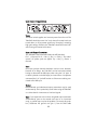
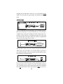
TUBE PAC
PROFESSIONAL TUBE PREAMPLIFIER/COMPRESSOR
USER’S GUIDE
TABLE OF CONTENTS
Introduction
Registration
Features
Overview
Setting Up
Unpacking
AC Power Hookup
Audio Connections
Installation
Safety Precautions
Powering Up
Front Panel Controls and Indicators
Gain Control
Gain Switch
Phantom Power Switch
Tube Drive/ Gain Reduction Display
Threshold Control
Slope Switch
Speed Switch
Phase Switch
Output Level Control
Bypass Switch
Rear Panel Connections
Power Switch
Input
Output
Applications
Tube Replacement
Specifications
On-line Information
Warranty Information
Service Information
131-5004-101
1
2
2
3
4
5
5
5
5
5
6
6
6
6
7
7
8
8
9
9
9
10
10
11
11
11
11
12
13
14
15
16
16
Introduction
Thank you for purchasing Applied Research and Technology’s
Tube PAC. You’ve undoubtably noticed that the Tube PAC is as cool
sounding as it looks. After getting familiar with the Tube PAC,
you’ll realize what a great investment you’ve just made. The Tube
PAC may be used everywhere! Anywhere you need level adjustments (gain or attenuation), and anywhere you need compression
- you’ll be using the Tube PAC. Offering a superb level of sound
quality, the Tube PAC will enhance the sonic textures of your audio
system for years to come.
Registration
If you haven’t done so already, please take the time to fill out the
User Registration Card for your purchase. Having you in our database allows us to keep you informed of updates, application
notes, and new product introductions. It only takes a moment, and
it will ensure you are constantly up to date with your purchase.
Fill in the following for your future reference:
Date of purchase: ___________________
Purchased From: ____________________
Serial Number: 131-________
2
Features
The Tube PAC is a unique product. It contains two independent
award-winning circuit designs - one of the finest tube microphone
preamplifiers available and one of the finest optical tube compressors available. Developed in partnership with studio and live
sound engineers, the Tube PAC possesses a “sound” that is not
available from any other product on the market - at any price! The
Tube PAC was designed and constructed with the best components, assuring a lifetime of quiet, reliable performance. The Tube
PAC offers:
-
The award-winning A R T “SOUND”!
Tube-based mic/line preamplifier
Tube-based optical compressor
Hand-selected 12AX7a tubes
VCA-less compressor circuitry = transparent dynamics control
Unique tube drive and gain reduction metering
Bypassable compression circuitry
XLR balanced inputs and outputs
1/4” TS unbalanced inputs and outputs
Custom extruded aluminum chassis
+48V phantom power
Phase reversal
Over 70dB of gain
Independent input and output level controls
Detented rotary controls
Compression and limiting ratios
Selectable release time settings
>90dB dynamic range
Internal power supply
One year warranty
Designed and manufactured in the USA
3
OVERVIEW
The Tube PAC (PreAmplifier/Compressor) is a multi-purpose tool
for audio engineering and recording. Enclosed in a table-top (and
1/2 rack-able) chassis are two independent circuits featuring a
tube-based analog preamplifier and a VCA-less, tube-based
compressor with optical gain reduction control. Used as a mic/line
preamp or as a DI (direct) box, the Tube PAC is designed to work
seamlessly with any recording, sound-reinforcement, or electronic
instrument setup.
A R T’s Tube PAC circuitry is a hybrid design utilizing the latest,
most advanced, solid-state and tube technology. Using a transformerless design throughout, the Tube PAC maintains exceptional signal integrity and extremely low noise. The compressor circuit
follows the preamp. While the preamp is always active, the compressor may be bypassed.
The preamplifier’s active balanced solid-state input provides
extremely low noise and excellent CMRR. The 1/4” input has a
high impedance, which prevents the loading of any device connected to it and makes the Tube PAC perfect for DI or line level
applications. The preamplifier’s second stage 12AX7a tube runs
on a regulated DC voltage providing an additional 40dB of gain.
Our design causes the tube to overload before the input or output
stage. This allows you to manipulate the tube gain to meet different sonic requirements.
The compression circuit features a VCA-less design and utilizes
optical electronics (Vactrol) coupled with a 12AX7 vacuum tube
gain stage for superior musical performance. The compressor is
soft knee by design. Although it is capable of providing a thoroughly “squashed” signal, it was designed to excel in areas where
transparent and musical dynamics control is desired. The beauty
of the optical/tube design is its ability to apply heavy amounts of
compression without pumping and breathing like VCA-based
compressors. In many cases you will hear the results of the com-
4
pression without hearing the compressor.
SETTING UP
Unpacking
Your Tube PAC was packed with care at the factory. The shipping
carton was designed to protect it during initial shipment. Please
retain this carton for use in transporting the Tube PAC, or in the
unlikely event that you need to return your Tube PAC for servicing.
AC Power Hookup
The Tube PAC has an internal power supply designed to operate
at 100 to 125VAC, 50 to 60Hz. Units manufactured for use outside of the United States of America have been modified to comply with the required electrical specifications. Under no circumstances should the power cable be altered. If the cable becomes
cut or damaged, discontinue its use and have it replaced before
operating the Tube PAC.
Audio Connections
Audio connections to and from the Tube PAC are balanced XLR
(Pin 2 Hot (+), Pin 3 Cold (-), Pin 1 Ground) and unbalanced 1/4”
(Tip Hot (+), Sleeve Ground.) We recommend using only highquality cables equipped with the appropriate connectors.
Installation
The Tube PAC may be employed in a number of setups
including:
- Between a microphone and a mixer, digital multi-track recorder,
DAT machine, hard disk recorder, or analog recorder.
- In a mixer’s channel insert points.
- Between a microphone and signal processors.
- Between electronic musical instruments (synthesizers, guitars,
bass, samplers, acoustic instruments with pickups) and
other gear.
5
SAFETY PRECAUTIONS
Warning: To avoid the risk of shock or fire, do not expose this unit
to moisture. Do not remove metal panels from chassis parts.
Removing the chassis from its cabinet parts exposes dangerous
high voltages. There are no user-serviceable parts inside. Refer all
servicing to qualified personnel. Note: If your power cord
becomes damaged and must be replaced, always replace it with
the proper type (3 prong.)
POWERING UP
When the rear panel power switch is turned on, the power indicator LED will illuminate. It is important to remember to turn the Tube
PAC on before any monitoring levels or power amps are turned
on. The Tube PAC has the ability to add over 60dB of gain to its
input signal. This can cause the Tube PAC to produce a “thump”
on power up and power down.
Note: Like all tube-based equipment, the Tube PAC needs to warm
up before being used. Allow one to two minutes for the tubes to
reach proper operating temperature before using.
If the Tube PAC fails to power up when the power switch is turned
on, check to see that its power cord is plugged into an active outlet. If the unit still fails to operate properly, turn it off and unplug
it. Then consult your dealer or A R T’s Customer Service department.
FRONT PANEL CONTROLS & INDICATORS
Gain Control
The Gain control sets the amount of input gain of the Tube PAC.
Turn the control clockwise to increase gain and counterclockwise
6
to decrease gain. Selection of the gain range is made with the
+20dB gain switch. You may control two ranges of gain with this
control, +26 to +60dB and +6 to +40dB. When setting the Gain
control, refer to the 4 segment Tube Drive Array for a visual reference to the Tube PAC’s internal signal levels (applied gain). Hint:
the “sweet” spot for the Tube PAC is when the second warm LED
in the Tube Drive array is lit.
Gain Switch
Use the Gain switch to set the range of the Gain control. When the
switch is in the out (0db) position the gain range is +6 to +40dB.
Depressing the switch adds 20dB of gain. With the switch in, the
gain range is +26 to +60dB. With most microphone applications
you’ll find using the Tube PAC with the +20dB gain switch in is
needed. Use the setting that best fits your application.
Phantom Power Switch
The Tube PAC can power any microphone needing +48 volts DC
phantom power. Consult your microphone’s documentation to see
if phantom power is required to power it. Phantom power is turned
on and off with this switch and supplies power to pins 2 and 3 of
the XLR input jack. It is best to have phantom power turned off
when connecting microphones to the Tube PAC.
Note: Be sure to turn down or mute the output of the Tube PAC
when engaging or disengaging phantom power. Additionally,
when disengaging, allow 30 - 45 seconds for the power to completely dissipate. Most microphones will make a sound like air
leaking from a tire when phantom power is disconnected, but
some can make some very nasty low rumbles and whines as well.
Another Note: MOST dynamic microphones should not be affected or damaged if they are plugged into the Tube PAC when phantom power is turned on (we haven’t run across any). However, if
the mic doesn’t need it, don’t use it. Some things are best left
untested!
7
Tube Drive/Gain Reduction Display
Four LEDs display how the tube gain is affecting the input signal.
These LEDs are calibrated with the tube circuitry to give you an
Note: these
accurate representation of the tube’s output signal (N
LEDs measure the signal level before the output level control). Use
this meter as a visual for setting the Gain level. The first LED is
labeled “Cln”. The tube is producing a clean output when this LED
is lit.
The next two LEDs are labeled “warm.” This is the optimal operating range for the Tube PAC. At this level, the tube is producing
an output signal which most would term “warm” (Whatever you
would like to call it is fine - simmering, toasty, etc.) You’ll find the
output signal has an enhanced bottom to low mid quality with
smooth high frequency detail.
The last LED is labeled “Clip.” This LED will light approximately
6dB before audible distortion occurs. If this light flickers, do not
panic. The unique design of the Tube PAC allows the tube to distort well before any other gain stage. When a tube goes into distortion it is a gradual process and tends to sound pleasing for a
range before it turns into a distortion box. After some use you’ll
find the “sweet spot” of the Tube PAC is with this light flashing fairly regularly. You may find a “clipped” level is suitable for some
applications.
Note: Use the Tube Character Array to aid in setting the Input
Level Control.
Threshold Control
The Threshold control sets the point at which the compressor circuit will act on the input signal. Turning this control counterclockwise lowers the threshold (adding more compression to a signal).
Turning this control clockwise raises the threshold.
Setting the Threshold control is dependent on the Gain control.
8
The easiest way to set the threshold control is to start with the control fully clockwise. After setting the Gain control, slowly turn the
Threshold control counter-clockwise (lowering threshold) until you
see the yellow (0dB) Threshold LED light. Now adjust the control
(either lower or higher) until you have the amount of compression
you desire. Use the Gain Reduction meter as a visual guide to the
amount of compression applied.
Slope Switch
In its “out” position, the Tube PAC’s compression ratio is an active
2.3:1 ratio. This means that for every 2.3dB over the threshold the
input signal rises, the compressor’s output will change by 1dB.
This is a very mild and musical compression ratio which is ideal
for smoothing all types of signals.
In its “in” position, the compression ratio is greater than 6:1. This
is typically called “soft limiting” as it allows only a 1dB change in
signal level for any signal reaching over 6dB over the set threshold. This setting is ideal for applications where exceeding a set
level is not desirable (mixing, popping bass, digital recording,
etc.).
Speed Switch
The position of the Speed switch selects the release characteristics
of the Tube PAC’s compressor. The “out” position allows the compressor to recover quickly once the signal falls below the threshold. The “in” position allows the compressor to adjust itself
depending on the characteristics of the input signal. Use the “fast”
setting when the signal has repetitive, consistent characteristics
(kick drum, snare, vocals, etc.). Use the “auto” setting when the
signal has varying characteristics (long decaying notes alternating
with quick notes, mix material, etc.).
Phase Switch
The Phase switch is provided to reverse the phase of a signal. This
switch works on Pins 2 and 3 of the XLR Output jack. The Phase
9
switch also reverses the polarity of the 1/4” output jack. In the
Normal (out) position, the signal is in-phase. In the Reverse (in)
position, Pins 2 and 3 are reversed as the signal is changed to 180
degrees out of phase.
In multiple microphone applications, the placement of the microphones can affect the phase of a signal. If two microphones pick
up the same signal from different locations, the result can be a
hollow or frequency “shifted” sound. In some cases it may sound
as if an instrument disappears if it happens to be 180 degrees out
of phase. Depressing the Phase switch can remedy this problem.
Likewise, if a microphone cable is wired incorrectly, when used
with a properly wired cable the signal will be out of phase.
Note: for single microphone applications, switching the phase
switch in and out will produce little to no change in the output signal.
Output Level Control
The Output Level control sets the output level of the Tube PAC.
When the control is fully counterclockwise, there is no output.
Turning the control clockwise increases the level of the output to a
maximum of +10dB of gain. When setting the Output Level control, refer to the level meter on your recorder or mixer.
Bypass Switch
A Bypass switch is included on the Tube PAC to enable you to
remove the compressor from your signal chain. When set to its
“in” (bypass) position, signal is allowed to pass from the preamp
circuitry to the output jacks with no compression. The LED will glow
red when Bypass is engaged. This informs you that the compressor is bypassed. In its “out” position, the compressor is active. Use
the Bypass switch when setting the Tube PAC’s Output Level to
achieve unity (no boost or cut) gain. Unity gain is achieved when
the active level is the same as the bypassed level.
10
REAR PANEL CONNECTIONS
Power
The Power switch supplies and removes power from the unit. The
Tube PAC should be turned “on” only when all monitor levels are
turned down, or off, to protect against any “thumping” caused by
high gain settings. Likewise, the Tube PAC should be turned “off”
after turning all monitor levels down.
Input and Output Connections
The Tube PAC’s XLR connectors follow the AES standard:
Pin 1 = Ground, Pin 2 = Hot (+), Pin 3 = Cold (-). The unbalanced 1/4” phone jacks are typical Tip = Hot (+), Sleeve =
Ground.
Input
One input jack per channel should be used at a time. However,
because of its design, the Tube PAC can be hard-wired without
having to disconnect the XLR inputs when using the 1/4” jacks. If
no load is placed on the XLR input (no instrument or microphone
connected) the 1/4” jack will function as if there was nothing connected to the XLR input.
Output
Both balanced and unbalanced output connections may be used
simultaneously. This is particularly useful when using the Tube PAC
as a direct box for instruments or line level signals.
Note: If you experience a hum when using both output connectors
simultaneously (one to the console and one to an instrument
amp), a ground loop may be the problem. To remedy this problem, disconnect the ground wire (pin 1) from the XLR cable
11
plugged into the Tube PAC’s output (or use a ground-lifted audio
cable). This interrupts the ground path and therefore breaks the
loop.
APPLICATIONS
The main application of the Tube PAC is as a microphone preamplifier and compressor. To use the Tube PAC as a mic or line preamplifier only, simply press the Bypass switch to bypass the compression circuitry. Plug any microphone directly into either input
and set the input and output controls to provide an appropriate
level into the next stage of your system.
The Tube PAC is ideal for use as a DI box. Plug the instrument into
either input and use the XLR, 1/4, or both outputs to connect to
your recorder, board, or PA system. Experiment with different input
level settings for different textures.
In most cases the Tube PAC offers superior performance to the onboard preamp on your console. To use the Tube PAC instead of
your on-board preamp, simply connect the output of the Tube PAC
to the line input of your mixer’s input channel. Note: you can con-
12
nect the XLR output jack of the Tube PAC to the XLR input of your
mixer, however most affordable mixers do not allow you to bypass
their internal preamp when using the XLR jack. You will cause no
harm to either unit when doing this but you will probably experience slightly higher noise. This is due to the fact that you are now
preamplifing your mixer’s preamp.
Mastering (2-mix processing)
Because of its low noise and excellent tonal qualities, the Tube PAC
is ideal to run mixes through before recording to DAT or cassette.
Used as a mastering device, the Tube PAC is capable of adding
warmth and gentle tube compression to the incoming signal.
Low noise, compression and variable Input and Output level controls make the Tube PAC ideal for level matching material in post
production situations.
Special Effects
For industrial, metal, or just “flavor” textures, experiment with the
Tube PAC. Overdriving the preamp and compressor circuitry can
add interesting textures when blended with vocals and other
instruments. Placing signals purposely out of phase can also yield
interesting results. No harm will come to the Tube PAC with this
type of experimentation. However, be sure to have output and
monitoring levels turned DOWN before “testing” the sound.
Remember, you have a great amount of gain available in the Tube
PAC!
TUBE REPLACEMENT
The Tubes in your Tube PAC should last for many years. The tubes
used in your unit are hand-sorted for performance. In the event
that you need to replace them, A R T suggests that you do so with
tubes available from A R T. These are matched to the Tube PAC
and will yield consistent sonic results. You can replace the tubes
with other brands, however A R T has no responsibility for the
resulting sound quality. They may sound better, they may sound
13
worse. The choice is yours. Please realize that unauthorized alterations to the Tube PAC will result in voiding the warranty.
A R T Tube PAC SPECIFICATIONS
Dimensions
5.25"D x 8.5"W x 1.65"H
Weight
6.0 lbs
Maximum Gain
XLR to XLR
70dB
1/4” to 1/4”
67dB
Phantom Power
+48v DC (switchable)
Compression Ratio
2.3:1 (comp)/ 6:1 (lim)
Attack Time
6.5ms
Release Time
200ms (fast), 70ms-1sec (auto)
Equivalent Input Noise
-129dBu (XLR to XLR, ‘A’ weighted)
Dynamic Range
>90dB (no weighting)
Input Impedance
1.67k ohms (XLR), 1M ohm (1/4”)
Output Impedance
600 ohms (XLR), 300 ohms (1/4”)
Maximum input Level
+15dBu (XLR), +21dBu (1/4”)
Maximum Output Level
+27dBu (XLR), +22dBu (1/4”)
CMRR
90dB (typical)
THD
<0.1% (typical)
Tubes
Two Hand-Selected 12AX7a
Power Requirements
100-125 VAC, 16W (Export units configured for country of destination)
A R T retains a policy of constant product improvement. A R T reserves the right to
make changes in design or make additions to or improvements upon this product
without any obligation to install the same on products previously manufactured. In
other words, specifications are subject to change without notice.
Designed and manufactured in the United States of America.
Applied Research and Technology, Inc.
215 Tremont Street
Rochester, NY 14608 USA
(716) 436-2720 (Phone)
(716) 436-3942 (FAX)
14
WE’RE ON-LINE!
For Product information, questions, applications, tips, answers and general discussion with A R T employees look for A R T on the Internet..
Look for the A R T folder on America Online in Craig Anderton’s Stage Studio and
Sound (keyword “SSS”) under the Manufacturer Supported Forums. Email us at
[email protected]
Look for the A R T supported area in the MIDI Forum B area on CompuServe (Go
MIDI). CompuServe address: 76702,3700. Email us at [email protected]
Check out our Web Page at: http:\\www.artroch.com
15
WARRANTY AND SERVICE INFORMATION
Limited Warranty
Warranty service for this unit will be provided by Applied Research and Technology,
Inc. in accordance with the following warranty statement.
Applied Research and Technology, Inc. (A R T) warrants to the original purchaser
that this product is free from defects in workmanship and materials for a period of
one year from the date of purchase. A R T will, without charge, repair or replace,
at its option, defective product or component parts upon prepaid delivery to the
factory service department or an authorized service center, accompanied by proof
of purchase date in the form of a valid sales receipt.
EXCLUSIONS: This warranty does not apply in the event of misuse or abuse of the
product or as a result of unauthorized alterations or repairs. This warranty is void
if the serial number is altered, defaced or removed.
A R T reserves the right to make changes in design and make additions or improvements upon this product without any obligation to install the same on products previously manufactured.
A R T should not be liable for any consequential damages, including without limitation damages resulting from the loss of use. Some states do not allow limitation
of incidental or consequential damages, so the above limitation or exclusion may
not apply to you. This warranty gives you specific rights and you may also have
other rights which vary from state to state.
For products purchased outside the United States, service will be provided by an
authorized distributor of Applied Research and Technology, Inc. products.
SERVICE
The following information is provided in the unlikely event that your unit requires
service. Use this procedure to return units in the United States only. For service outside the United States, please contact your authorized A R T distributor.
1) Be sure the unit is the cause of the problem. Check to make sure the unit has
power supplied, all cables are connected correctly, and the cables themselves are
in working condition.
2) If you find the unit to be at fault, write down a description of the problem, including how and when the problem occurs.
3) Call the factory for a Return Authorization (RA) number.
4) Pack the unit in its original carton or reasonable substitute. The packing box is
not recommended for a shipping carton. Put the packaged unit in another box for
shipping. Print the RA number clearly under the address.
16
5) Include with your unit: a return shipping address (we cannot ship to a P.O. Box),
a copy of your purchase receipt, a daytime phone number and the description of
the problem.
6) Ship the unit to:
Applied Research and Technology, Inc.
215 Tremont Street
Rochester, NY 14608
Atten: Repair Department
R.A.# _______________
7) Contact our Customer Service department at (716) 436-2720 for your Return
Authorization number or questions regarding your repair. Customer Service hours
are Monday through Friday 9:00AM to 5:00PM Eastern time.
©1997 Applied Research and Technology, Inc.
17