1
K2661
Musician’s Reference
©2003 All rights reserved. Kurzweil ® is a product line of Young Chang Co., Ltd. Young Chang®, Kurzweil ® , V. A. S. T. ®, KDFX®,
Pitcher®, and LaserVerb®, KSP8 ™, K2661™, K2600™, K2500™, and K2000™ are trademarks of Young Chang Co., Ltd. SmartMedia™ is a
trademark of Toshiba Corporation. ADAT® is a registered trademark of Alesis Corporation. All other products and brand names are
trademarks or registered trademarks of their respective companies. Product features and specifications are subject to change without notice.
You may legally print up to two (2) copies of this document for personal use. Commercial use of any copies of this document
is prohibited. Young Chang Co. retains ownership of all intellectual property represented by this document.
Part Number: 910400 Rev. A
The lightning flash with the arrowhead symbol,
within an equilateral triangle, is intended to alert
the user to the presence of uninsulated
"dangerous voltage" within the product's
enclosure that may be of sufficient magnitude
to constitute a risk of electric shock to persons.
CAUTION
RISK OF ELECTRIC SHOCK
DO NOT OPEN
CAUTION: TO REDUCE THE RISK OF ELECTRIC SHOCK,
DO NOT REMOVE THE COVER
NO USER SERVICEABLE PARTS INSIDE
REFER SERVICING TO QUALIFIED SERVICE PERSONNEL
The exclamation point within an equilateral
triangle is intended to alert the user to the
presence of important operating and
maintenance (servicing) instructions in the
literature accompanying the product.
IMPORTANT SAFETY & INSTALLATION INSTRUCTIONS
INSTRUCTIONS PERTAINING TO THE RISK OF FIRE, ELECTRIC SHOCK, OR INJURY TO PERSONS
WARNING: When using electric products, basic precautions should
always be followed, including the following:
1. Read all of the Safety and Installation Instructions and Explanation
of Graphic Symbols before using the product.
2. This product must be grounded. If it should malfunction or break
down, grounding provides a path of least resistance for electric
current to reduce the risk of electric shock. This product is equipped
with a power supply cord having an equipment-grounding
conductor and a grounding plug. The plug must be plugged into an
appropriate outlet which is properly installed and grounded in
accordance with all local codes and ordinances.
DANGER: Improper connection of the equipment-grounding
conductor can result in a risk of electric shock. Do not modify the
plug provided with the product - if it will not fit the outlet, have a
proper outlet installed by a qualified electrician. Do not use an
adaptor which defeats the function of the equipment-grounding
conductor. If you are in doubt as to whether the product is properly
grounded, check with a qualified serviceman or electrician.
3. WARNING: This product is equipped with an AC input voltage
selector. The voltage selector has been factory set for the mains
supply voltage in the country where this unit was sold. Changing
the voltage selector may require the use of a different power supply
cord or attachment plug, or both. To reduce the risk of fire or
electric shock, refer servicing to qualified maintenance personnel.
4. Do not use this product near water - for example, near a bathtub,
washbowl, kitchen sink, in a wet basement, or near a swimming
pool, or the like.
5. This product should only be used with a stand or cart that is
recommended by the manufacturer.
6. This product, either alone or in combination with an amplifier and
speakers or headphones, may be capable of producing sound
levels that could cause permanent hearing loss. Do not operate for
a long period of time at a high volume level or at a level that is
uncomfortable. If you experience any hearing loss or ringing in the
ears, you should consult an audiologist.
7.
8.
9.
10.
11.
12.
13.
14.
15.
The product should be located so that its location or position does
not interfere with its proper ventilation.
The product should be located away from heat sources such as
radiators, heat registers, or other products that produce heat.
The product should be connected to a power supply only of the type
described in the operating instructions or as marked on the product.
This product may be equipped with a polarized line plug (one blade
wider than the other). This is a safety feature. If you are unable to
insert the plug into the outlet, contact an electrician to replace your
obsolete outlet. Do not defeat the safety purpose of the plug.
The power supply cord of the product should be unplugged from the
outlet when left unused for a long period of time. When unplugging
the power supply cord, do not pull on the cord, but grasp it by the
plug.
Care should be taken so that objects do not fall and liquids are not
spilled into the enclosure through openings.
The product should be serviced by qualified service personnel
when:
A. The power supply cord or the plug has been damaged;
B. Objects have fallen, or liquid has been spilled into the product;
C. The product has been exposed to rain;
D. The product does not appear to be operating normally or
exhibits a marked change in performance;
E. The product has been dropped, or the enclosure damaged.
Do not attempt to service the product beyond that described in the
user maintenance instructions. All other servicing should be
referred to qualified service personnel.
WARNING: Do not place objects on the product's power supply
cord, or place the product in a position where anyone could trip
over, walk on, or roll anything over cords of any type. Do not allow
the product to rest on or be installed over cords of any type.
Improper installations of this type create the possibility of a fire
hazard and/or personal injury.
RADIO AND TELEVISION INTERFERENCE
WARNING: Changes or modifications to this instrument not expressly
approved by Young Chang could void your authority to operate the
instrument.
IMPORTANT: When connecting this product to accessories and/or other
equipment use only high quality shielded cables.
NOTE: This instrument has been tested and found to comply with the
limits for a Class B digital device, pursuant to Part 15 of the FCC Rules.
These limits are designed to provide reasonable protection against
harmful interference in a residential installation. This instrument
generates, uses, and can radiate radio frequency energy and, if not
installed and used in accordance with the instructions, may cause
harmful interference to radio communications. However, there is no
guarantee that interference will not occur in a particular installation. If
this instrument does cause harmful interference to radio or television
reception, which can be determined by turning the instrument off and on,
the user is encouraged to try to correct the interference by one or more
of the following measures:
• Reorient or relocate the receiving antenna.
• Increase the separation between the instrument and the receiver.
• Connect the instrument into an outlet on a circuit other than the one
to which the receiver is connected.
• If necessary consult your dealer or an experienced radio/television
technician for additional suggestions.
NOTICE
This apparatus does not exceed the Class B limits for radio noise
emissions from digital apparatus set out in the Radio Interference
Regulations of the Canadian Department of Communications.
AVIS
Le present appareil numerique n’emet pas de bruits radioelectriques
depassant les limites applicables aux appareils numeriques de la
class B prescrites dans le Reglement sur le brouillage radioelectrique
edicte par le ministere des Communications du Canada.
SAVE THESE INSTRUCTIONS
ii
Important Safety Instructions
1)
2)
3)
4)
5)
6)
7)
Read these instructions
Keep these instructions.
Heed all warnings.
Follow all instructions.
Do not use this apparatus near water.
Clean only with dry cloth.
Do not block any of the ventilation openings. Install in accordance with the manufacturer’s
instructions.
8) Do not install near any heat sources such as radiators, heat registers, stoves, or other apparatus (including amplifiers) that produce heat.
9) Do not defeat the safety purpose of the polarized or grounding-type plug. A polarized plug
has two blades with one wider than the other. A grounding type plug has two blades and a
third grounding prong. The wide blade or the third prong are provided for your safety. If the
provided plug does not fit into your outlet, consult an electrician for replacement of the obsolete outlet.
10) Protect the power cord from being walked on or pinched, particularly at
plugs, convenience receptacles, and the point where they exit from the apparatus.
11) Only use attachments/accessories specified by the manufacturer.
12) Use only with a cart, stand, tripod, bracket, or table specified by the manufacturer, or sold with the apparatus. When a cart is used, use caution when
moving the cart/apparatus combination to avoid injury from tip-over.
13) Unplug this apparatus during lightning storms or when unused for long periods of time.
14) Refer all servicing to qualified service personnel. Servicing is required when the apparatus
has been damaged in any way, such as power-supply cord or plug is damaged, liquid has
been spilled or objects have fallen into the apparatus, the apparatus has been exposed to rain
or moisture, does not operate normally, or has been dropped.
Warning- To reduce the risk of fire or electric shock, do not expose this apparatus to rain or moisture. Do not expose this equipment to dripping or splashing and ensure that no objects filled with
liquids, such as vases, are placed on the equipment.
To completely disconnect this equipment from the AC Mains, disconnect the power supply cord
plug from the AC receptacle.
iii
Kurzweil International Contacts
Contact the nearest Kurzweil office listed below to locate your local Kurzweil representative.
Kurzweil Co., Ltd.
Daerung Technotown 6th, 306
493-6 Gasan, Gumcheon, Seoul, Korea
Tel: (+82) 2-2108-5700
Fax: (+82) 2-2108-5729
A N D Music Corp.
P.O. Box 99995
Lakewood, WA 98499-0995, USA
Tel: (253) 589-3200
Fax: (253) 984-0245
Young Chang Canada Corp.
250 Victoria Park Ave. Suite # 105
Toronto, Ontario Canada M2H 3P7
Tel: (905) 948-8052
Team Kurzweil Europe
Gl. Donsvej 8
6000 Kolding
Phone: (+45) 75 56 96 44
Fax: (+45) 75 56 96 55
Official distributors in other countries are listed on the web site.
World Wide Web Home Page:
http://www.kurzweilmusicsystems.com
iv
Contents
Kurzweil International Contacts..................................................................................................................................... iv
World Wide Web Home Page: ......................................................................................................................................... iv
Chapter 1
Front Panel
Front Panel Quick Reference ......................................................................................................................................... 1-1
Volume Knob/ Slider .............................................................................................................................................. 1-1
Mode Buttons............................................................................................................................................................ 1-1
Chan/Bank Buttons ................................................................................................................................................. 1-1
Edit Button ................................................................................................................................................................ 1-1
Soft Buttons ............................................................................................................................................................... 1-2
Exit Button................................................................................................................................................................. 1-2
Cursor Buttons.......................................................................................................................................................... 1-2
Alpha Wheel ............................................................................................................................................................. 1-2
Plus / Minus Buttons (- and +) .............................................................................................................................. 1-2
Alphanumeric Buttonpad ....................................................................................................................................... 1-2
The Display ............................................................................................................................................................... 1-3
Solo Button................................................................................................................................................................ 1-3
Mixdown Button ...................................................................................................................................................... 1-3
MIDI Faders button ................................................................................................................................................. 1-4
Assignable Controllers (Buttons 1–8 and Sliders A–H)...................................................................................... 1-4
PSw1, PSw2 (Buttons 9 and 10).............................................................................................................................. 1-4
Record, Play/Pause, Stop ....................................................................................................................................... 1-4
Special Button Functions................................................................................................................................................ 1-4
Special Button Functions: Double Button Presses ...................................................................................................... 1-6
Chapter 2
LFOs
LFO Shapes ...................................................................................................................................................................... 2-1
Chapter 3
DSP Algorithms
Chapter 4
Control Sources
Control Source Lists ........................................................................................................................................................ 4-3
Descriptions of Control Sources.................................................................................................................................... 4-4
MIDI Control Source List ............................................................................................................................................... 4-5
Main Control Source List ............................................................................................................................................... 4-8
Constant Control Sources............................................................................................................................................. 4-15
Keyboard Shortcuts for Control Sources ................................................................................................................... 4-16
Chapter 5
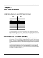
MIDI Note Numbers
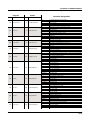
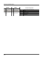
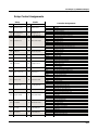
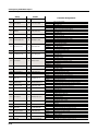
K2661 Note Numbers and MIDI Note Numbers........................................................................................................ 5-1
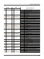
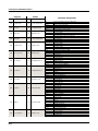
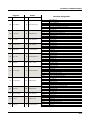
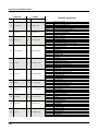
Note Numbers for Percussion Keymaps ..................................................................................................................... 5-1
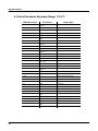
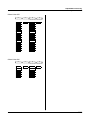
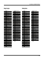
5-Octave Percussion Keymaps (Range: C2–C7).................................................................................................. 5-2
2-Octave Percussion Keymaps (Range: C3 - C5) ................................................................................................ 5-3
K2661 Musician’s Reference
Chapter 6
MIDI, SCSI, and Sample Dumps
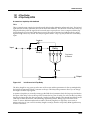
SCSI Guidelines ............................................................................................................................................................... 6-1
Disk Size Restrictions .............................................................................................................................................. 6-1
Configuring a SCSI Chain....................................................................................................................................... 6-1
K2661 and Macintosh Computers 6-3
The MIDI Sample Dump Standard............................................................................................................................... 6-4
Loading Samples with the MIDI Standard Sample Dump ................................................................................ 6-4
Getting a Sample into a Sample Editor from the K2661..................................................................................... 6-5
Loading a Sample into the K2661 from another K2661 ...................................................................................... 6-5
Dumping from the K2661 to a Sampler ................................................................................................................ 6-5
Dumping a Sample from the K2661 to a MIDI Data Recorder.......................................................................... 6-5
Loading a Sample into the K2661 from a MIDI Data Recorder......................................................................... 6-5
Accessing a New K2661 Sample ............................................................................................................................ 6-6
Troubleshooting a MIDI Sample Dump ............................................................................................................... 6-6
Aborting a MIDI Sample Dump ............................................................................................................................ 6-7
SMDI Sample Transfers .................................................................................................................................................. 6-8
Chapter 7
System Exclusive Protocol
K2661 System Exclusive Implementation.................................................................................................................... 7-1
Common Format ...................................................................................................................................................... 7-1
Messages.................................................................................................................................................................... 7-3
Master Parameters ................................................................................................................................................... 7-7
Button Press Equivalence Tables............................................................................................................................ 7-7
Chapter 8
Maintenance and Troubleshooting
Preventive Maintenance................................................................................................................................................. 8-1
Cleaning Your K2661 ............................................................................................................................................... 8-1
Battery Replacement ....................................................................................................................................................... 8-2
Scanner Diagnostics ........................................................................................................................................................ 8-3
Maximizing Music and Minimizing Noise.................................................................................................................. 8-3
Ground Hum ............................................................................................................................................................ 8-4
Power Problems and Solutions ..................................................................................................................................... 8-5
Troubleshooting............................................................................................................................................................... 8-5
Other Possible Problems ......................................................................................................................................... 8-6
Chapter 9
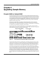
Upgrading Sample Memory
Program RAM vs. Sample RAM ................................................................................................................................... 9-1
Viewing RAM Objects ............................................................................................................................................. 9-2
Choosing and Installing a SIMM for K2661 Sample Memory .................................................................................. 9-2
SIMM Specifications ................................................................................................................................................ 9-2
Installing Sample RAM ........................................................................................................................................... 9-3
Chapter 10 KDFX Reference
In This Chapter .............................................................................................................................................................. 10-1
KDFX Algorithms.......................................................................................................................................................... 10-2
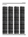
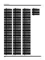
FX Presets ....................................................................................................................................................................... 10-3
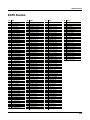
KDFX Studios................................................................................................................................................................. 10-5
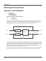
KDFX Algorithm Specifications .................................................................................................................................. 10-6
vi
K2661 Musician’s Reference
Chapter 11 Glossary
Chapter 12 Triple Modular Processing
Overview ........................................................................................................................................................................ 12-1
Triples and Polyphony .......................................................................................................................................... 12-2
Soloing and Muting ............................................................................................................................................... 12-2
KB3 Programs ......................................................................................................................................................... 12-2
Live Mode ............................................................................................................................................................... 12-2
Algorithms for Triple Modular Processing ........................................................................................................ 12-3
Compatibility with Other Kurzweil Instruments.............................................................................................. 12-3
Creating Triples ............................................................................................................................................................. 12-4
Editing Triples................................................................................................................................................................ 12-5
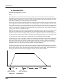
Amplitude Envelopes............................................................................................................................................ 12-6
Other Considerations ............................................................................................................................................ 12-9
Algorithm Reference................................................................................................................................................... 12-12
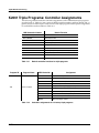
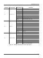
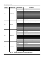
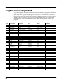
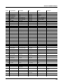
K2661 Triple Programs: Controller Assignments ................................................................................................... 12-36
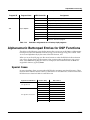
Alphanumeric Buttonpad Entries for DSP Functions............................................................................................ 12-39
Special Cases......................................................................................................................................................... 12-39
Appendix A Specifications
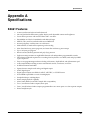
K2661 Features................................................................................................................................................................ A-1
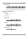
Environmental Specifications ....................................................................................................................................... A-2
Temperature Ranges ............................................................................................................................................... A-2
Relative Humidity Ranges (Non-condensing).................................................................................................... A-2
Physical Specifications................................................................................................................................................... A-2
Electrical Specifications ................................................................................................................................................. A-2
Safe Voltage Ranges ................................................................................................................................................ A-3
Analog Audio Specifications ........................................................................................................................................ A-3
Audio Jacks .............................................................................................................................................................. A-3
Separate Outputs..................................................................................................................................................... A-3
Mix Outputs............................................................................................................................................................. A-3
Headphone Output................................................................................................................................................. A-3
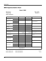
MIDI Implementation Chart......................................................................................................................................... A-4
Appendix B SysEx Control of KDFX
SysEx Message Structure................................................................................................................................................ B-1
Header ....................................................................................................................................................................... B-1
Body ........................................................................................................................................................................... B-2
End ............................................................................................................................................................................. B-2
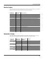
Device Codes.................................................................................................................................................................... B-3
Parameter Codes ............................................................................................................................................................. B-3
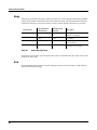
MSB and LSB.................................................................................................................................................................... B-4
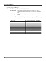
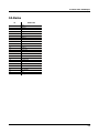
Appendix C Standard K2661 ROM Objects
Groove Setups...........................................................................................................................................................C-1
Special Purpose Setups............................................................................................................................................C-2
QA Banks...................................................................................................................................................................C-3
Setups.........................................................................................................................................................................C-4
Songs ..........................................................................................................................................................................C-5
Programs ...................................................................................................................................................................C-6
vii
K2661 Musician’s Reference
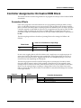
Appendix D Contemporary ROM Block Objects
Programs.......................................................................................................................................................................... D-2
Keymaps .......................................................................................................................................................................... D-3
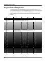
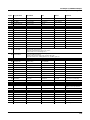
Program Control Assignments ..................................................................................................................................... D-4
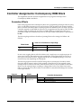
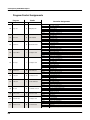
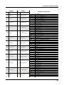
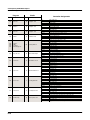
Controller Assignments: Contemporary ROM Block ............................................................................................... D-7
Secondary Effects .................................................................................................................................................... D-7
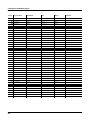
Program Control Assignments.............................................................................................................................. D-8
Setup Control Assignments ................................................................................................................................. D-17
Appendix E Orchestral ROM Block Objects
Programs........................................................................................................................................................................... E-2
Keymaps ........................................................................................................................................................................... E-3
Program Control Assignments ...................................................................................................................................... E-4
Controller Assignments: Orchestral ROM Block ........................................................................................................ E-7
Secondary Effects ..................................................................................................................................................... E-7
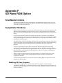
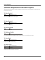
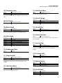
Appendix F SD Piano ROM Option
SmartMedia Contents ..................................................................................................................................................... F-1
Sympathetic Vibrations .................................................................................................................................................. F-1
Modifying SD Piano Programs .............................................................................................................................. F-1
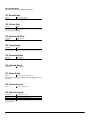
Controller Assignments for SD Piano Programs ........................................................................................................ F-2
Appendix G Vintage Electric Pianos ROM Option
Fender Rhodes......................................................................................................................................................... G-3
Wurlitzer................................................................................................................................................................... G-3
Hohner Pianet.......................................................................................................................................................... G-3
Yamaha CP-80.......................................................................................................................................................... G-4
RMI Electra-Piano ................................................................................................................................................... G-4
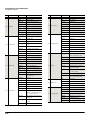
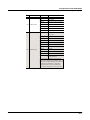
Vintage EP Programs ..................................................................................................................................................... G-5
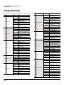
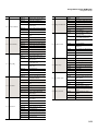
Vintage EP Setups ........................................................................................................................................................ G-18
Vintage Electric Piano Keymaps ................................................................................................................................ G-20
Vintage Electric Piano Samples .................................................................................................................................. G-20
Vintage Electric Piano Studios.................................................................................................................................... G-20
Appendix H General MIDI
Inside GM Mode............................................................................................................................................................. H-1
General MIDI Programs ................................................................................................................................................ H-2
GM Drum Kits ......................................................................................................................................................... H-3
Standard Mode Controller Assignments .................................................................................................................... H-4
Appendix I Live Mode Objects
Live Mode Programs ....................................................................................................................................................... I-1
Index
viii
Front Panel
Front Panel Quick Reference
Chapter 1
Front Panel
Front Panel Quick Reference
This section describes the features of the front panel of your K2661.
Volume Knob/ Slider
Controls mixed audio outputs and headphone jack only. Does not send MIDI Volume (MIDI 07).
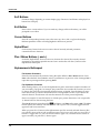
Mode Buttons
Press any of these eight buttons to enter the corresponding mode.
Chan/Bank Buttons
Scroll through the layers of the current program while in the Program Editor. Scroll through the
zones in the current setup while in Setup mode. Scroll through the Quick Access banks while in
Quick Access mode.
Edit Button
Functional in most modes. Press Edit to modify the currently selected object or parameter. If it’s
not editable, pressing Edit will do nothing. There are editors available from every mode but
Disk mode. The effect of pressing Edit in each of the modes is listed below.
When in this mode
Pressing the Edit button…
Program mode
…enters the Program Editor, where you can edit the currently selected program. Chapter 6
in the Musician’s Guide covers the Program Editor.
Setup mode
…enters the Setup Editor, where you can edit the currently selected setup. Chapter 7 in the
Musician’s Guide describes the Setup Editor.
Quick Access mode
…enters the Quick Access Editor, where you can change the program or setup assigned to
the bank slot that was selected when you entered the Quick Access Editor. See Chapter 8
in the Musician’s Guide.
Effects mode
…if the Studio parameter is highlighted, enters the Studio Editor, where you can edit the
currently selected studio. Chapters 9 and 15 in the Musician’s Guide explain studios, the
Studio Editor, FX presets, and the FX Preset Editor.
MIDI mode
…enters the Velocity Map or Pressure Map Editor if the Velocity or Pressure Map
parameter is selected on either the TRANSMIT page or the RECEIVE page. See Chapter
18 in the Musician’s Guide. Takes you to the Program Editor if the Program parameter is
selected on the CHANLS page. See Chapter 6 in the Musician’s Guide.
Master mode
…enters the Velocity Map, Pressure Map, or Intonation Table Editor if the VelTouch,
PressTouch, or Intonation parameter is selected. See Chapter 18 in the Musician’s Guide.
Song mode
…enters the Song Editor. The Song Editor is discussed in Chapter 12 in the Musician’s
Guide. Takes you to the Program Editor if the Program parameter is highlighted when Edit
is pressed.
Disk mode
…has no effect.
1-1
Front Panel
Front Panel Quick Reference
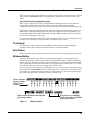
Soft Buttons
Functions change depending on current display page. Function of each button is displayed on
bottom line of display.
Exit Button
Press to leave various editors. If you’ve made any changes while in the editor, you will be
prompted to save them.
Cursor Buttons
Press the corresponding button to move the cursor up, down, left, or right in the display.
Different parameter values will be highlighted as buttons are pressed.
Alpha Wheel
For data entry. Rotate clockwise to increase value of currently selected parameter,
counterclockwise to decrease.
Plus / Minus Buttons (- and +)
Under the Alpha Wheel. Press to increase or decrease the value of the currently selected
parameter by the smallest possible amount. Don’t confuse this with the +/- button on the
alphanumeric buttonpad.
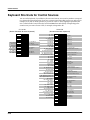
Alphanumeric Buttonpad
For Numeric Characters
Enter the value numerically instead of using the Alpha Wheel or Plus/Minus buttons. Press
Enter when finished. Press Cancel to restore a parameter to its previous value. Pressing Clear is
equivalent to pressing 0 without pressing Enter.
For Alphabetic Characters
When naming objects, you can use the alphanumeric pad to enter letters instead of numbers. If
you’re renaming a program, for example, just position the cursor under the character you want
to change, then press the corresponding numeric button, as labeled. Press the button as many
times as necessary to enter the desired character. Pressing Clear will enter a space before the
selected character. The 0 button will enter the numerals 0–9 when pressed repeatedly.
Here’s an example. To enter the letter C in a blank space, press 1 three times. You can press the
+/- button before or after entering the letter.
The Cancel button is equivalent to the >>> soft button, and Enter is the same as OK. The Clear
button replaces the currently selected character with a space. The +/– button toggles between
uppercase and lowercase letters.
When you press the +/– button on the alphanumeric pad, the currently selected character (the
one with the cursor under it) will switch from upper case to lower case, and vice versa. The +/–
button is a toggle; that is, if you switch from lower to upper case, all further entries will be in
upper case until you press the +/– button again.
1-2
Front Panel
Front Panel Quick Reference
There are several punctuation characters available as well, but they can be entered only with the
Alpha Wheel or Plus/Minus buttons. The punctuation characters are between z (lower case)
and 0.
Special Alphanumeric Buttonpad Functions
When you’re in Quick Access mode, the Alphanumeric buttonpad can be used to select the
entries in the current Quick Access bank. The layout of the alphanumeric buttonpad
corresponds to the layout of Quick Access bank entries as seen on the Quick Access-mode page.
There’s also a shortcut for selecting different QA banks while in QA mode. Just press the +/– or
Clear button on the alphanumeric pad, and you’ll be prompted to enter a bank number. Type
the desired number on the alphanumeric pad, then press Enter. The bank will be selected, and
you’ll return to the Quick Access page.
You can also use the alphanumeric pad to select strings to search for in the currently selected list
of objects, and to enter new strings to search for (see the Musician’s Guide.).
The Display
You may want to adjust the contrast and brightness of the display for different lighting
conditions. There are two adjustment knobs on the rear panel of the K2661.
Solo Button
Mutes all zones in setup except the current one. The button of the zone being soloed glows red.
Mixdown Button
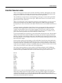
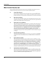
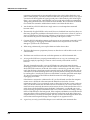
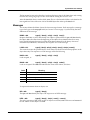
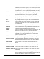
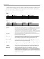
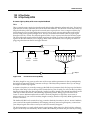
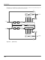
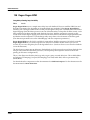
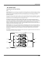
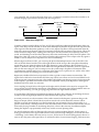
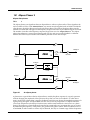
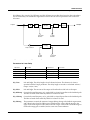
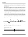
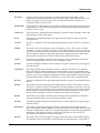
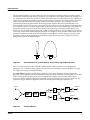
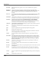
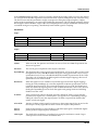
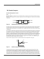
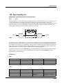
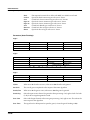
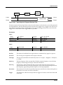
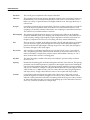
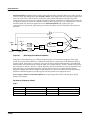
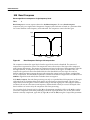
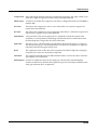
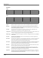
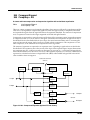
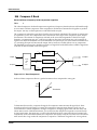
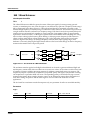
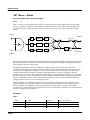
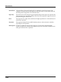
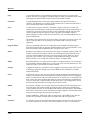
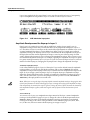
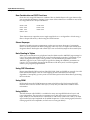
Brings up the Mixdown page, as shown in the following diagram. From this page you can
choose how the K2661’s physical sliders function during MIDI mixdown. In the example below,
Sliders A-H will control the volume level of MIDI channels 1-8. By pressing the Pan soft button,
you would change the function of the sliders to control panning for channels 1-8; or, you could
press the 9-16 soft button to have the sliders affect channels 9-16.
You can also use the cursor buttons to highlight the pan or volume control for a channel and use
the Alpha Wheel or Plus/Minus buttons to change the pan or volume level. In the screen below,
for example, you could use the Alpha Wheel to control panning on channel 9 at the same time
that you are using the sliders to control volume on channels 1-8.
Shows whether
physical sliders
control pan or
volume.
Mixdown||||<>Prog:|36|DuckWalk||||||||||
|||WXWXWXWX|WXWXWXWX|WXWXWXWX|WXWXWXWX||
|||wxwxC{wx|wxwxwxwx|wxwxwxwx|wxwxwxwx||
>>||z|z}~|z||z|z|z|z||z|z|z|z||z|z|z|z||
||||_|_|_|_||_|_|_|_||_|_|_|_||_|_|_|_||
||||||||||||||||||||||||||||||||||||||||
|||*****************||||||||||||||||||||
|Pan|||Volume|Ch|1-8|Ch9-16|||||||||Done
Shows which channels are affected
by physical sliders.
Figure 1-1
Soft buttons for indicating
which channels are affected
by physical sliders.
Mixdown Control
1-3
Front Panel
Special Button Functions
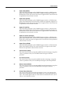
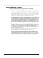
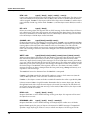
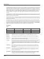
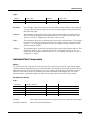
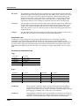
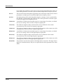
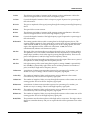
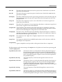
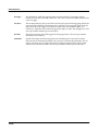
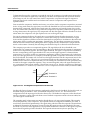
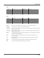
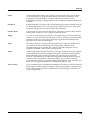
MIDI Faders button
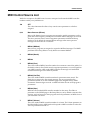
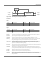
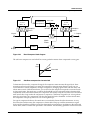
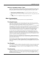
When you press the MIDI Faders button, the K2661’s sliders take on the functions assigned on
the current MIDI Faders page. From the MIDI Faders display you can define four different pages
that define how the K2661’s physical sliders will work. In the display shown below, for example,
the eight sliders are each defined to send MIDI 6 (Data) on Channels 9 through 16. Press one of
the Page soft buttons to use (or create) a different page of MIDI fader assignments. Use the Send
soft button to transmit values without moving the faders.
The MIDI Faders pages is saved as part of the Master table object.
MIDI|Faders:Page2|||||||||||||||||||||||
Chan|:|9|||10||11||12|||13|||14||15||16|
Ctl||:|6|||6|||6|||6||||6||||6|||6|||6||
Value:|0|||0|||0|||0||||0||||0|||0|||0||
||||||||||||||||||||||||||||||||||||||||
||||||\]||}~||\]||}~||||\]||}~||\]||}~||
|||||||_|||_|||_|||_|||||_|||_|||_|||_||
Page1||Page2||Page3||Page4|||Send|||Done
Assignable Controllers (Buttons 1–8 and Sliders A–H)
The function of these controllers will depend on how they’ve been defined within a setup.
Buttons 1–8 control either zone muting or KB3 features, depending on the value of the value of
the Mutes parameter on the COMMON page in the Setup Editor. The SLIDER and SLID/2 pages
configure the functions of Sliders A–H.
PSw1, PSw2 (Buttons 9 and 10)
The function of these controllers depends on how they’ve been defined on the SWITCH page in
the Setup Editor.
Record, Play/Pause, Stop
These buttons duplicate the functions of the corresponding soft buttons in Song mode, allowing
you to conveniently record, play, pause, and stop the current song.
Special Button Functions
The Mode buttons and the Chan/Bank Down button have additional functions, depending on
the mode or editor you’re in. When you’re in the Program or Setup Editor, they function
according to the blue labeling under each button. They also work as track mutes on the MIX
page of Song mode.
1-4
Front Panel
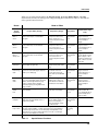
Special Button Functions
When you’re in the Sample Editor, the Program, Setup, Q Access, MIDI, Master, and Song
mode buttons function according to the orange labeling near each button. Table 1-1 describes all
of the special button functions.
Button
White
Orange
Light Grey
Mode or Editor
Program Editor (Orange)
Setup Editor (Orange)
Song Mode
Sample Editor (Light
Grey)
Program
Mute 1
Zoom-
Mutes Layer 1 of current program, or
mutes current layer of current drum
program
Mutes Zone 1 of current
setup if 3 or fewer zones;
mutes current zone of
current setup if more than 3
zones
On MIX page,
mutes Track 1
or 9
On TRIM and LOOP
pages, decreases
horizontal dimension of
current sample in
display
Setup
Mute 2
Zoom+
Mutes Layer 2 of current program, or
solos current layer of current drum
program
Mutes Zone 2 of current
setup if 3 or fewer zones;
solos current zone of
current setup if more than 3
zones
On MIX page,
mutes Track 2
or 10
On TRIM and LOOP
pages, increases
horizontal dimension of
current sample in
display
Q Access
Mute 3
Samp / Sec
Mutes Layer 3 of current program, or
solos current layer of current drum
program
Mutes Zone 3 of current
setup if 3 or fewer zones;
solos current zone of
current setup if more than 3
zones
On MIX page,
mutes Track 3
or 11
Toggles between units
used to identify location
within sample— either
number of samples from
start, or time in seconds
from start
Effects
FX Bypass
Bypasses (mutes) current program’s FX
preset (plays program dry)
Bypasses (mutes) current
setup’s studio (plays studio
dry)
On MIX page,
mutes Track 4
or 12
MIDI
Previous Pg
Gain -
Successive presses take you back to
four most recent editor pages; 5th press
takes you to ALG page
Successive presses take
you back to four most
recent editor pages; 5th
press takes you to CH/PRG
page
On MIX page,
mutes Track 5
or 13
On TRIM and LOOP
pages, decreases
vertical dimension of
current sample in
display
Master
Mark
Gain +
“Remembers” current editor page, so
you can recall multiple pages with Jump
button; asterisk appears before page
name to indicate that it’s marked;
unmark pages by pressing Mark when
page is visible
Same as for Program
Editor; pages common to
both editors are marked or
unmarked for both editors
On MIX page,
mutes Track 6
or 14
On TRIM and LOOP
pages, increases
vertical dimension of
current sample in
display
Song
Jump
Link
Jumps to marked pages in order they
were marked
Jumps to marked pages in
order they were marked
On MIX page,
mutes Track 7
or 15
Preserves interval
between Start, Alt,
Loop, and End points of
current sample; press
again to unlink
Disk
Compare
Negates effect of unsaved edits and
plays last-saved (unedited) version of
object being edited
Same as for Program
mode; display reminds you
that you’re comparing;
press any button to return
to edited version
On MIX page,
mutes Track 8
or 16
Chan / Bank
Layer / Zone
In Program Editor, these two buttons scroll through layers of current
program; in Effects Editor, scroll through FX presets; in Keymap Editor,
scroll through velocity levels of current keymap; in Setup Editor, scroll
through zones of current setup; in Quick Access mode, scroll through
entries in current Quick Access bank
Edit
Whenever cursor is highlighting an editable object or parameter, takes you to corresponding editor or programming page
Table 1-1
Change
recording
track
Special Button Functions
1-5
Front Panel
Special Button Functions: Double Button Presses
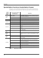
Special Button Functions: Double Button Presses
Pressing two or more related buttons simultaneously executes a number of special functions
depending on the currently selected mode. Make sure to press them at exactly the same time.
In this
mode or
editor…
Program
mode
Master mode
Song mode
Disk mode
Program
Editor
Keymap
Editor
Sample
Editor
Any Editor
Save Dialog
…pressing these buttons
simultaneously…
Octav-, Octav+
Reset MIDI transposition to 0 semitones. Double-press again to
go to previous transposition.
Chan–, Chan+
Set current MIDI channel to 1.
Plus/Minus
Step to next Program bank (100, 200, etc.)
Chan/Bank
Enables Guitar/Wind Controller mode.
Left/Right cursor buttons
Toggle between Play and Stop.
Up/Down cursor buttons
Toggle between Play and Pause.
Chan/Bank
Select all tracks on any TRACK page in Song Editor.
2 leftmost soft buttons
Issue SCSI Eject command to currently selected SCSI device.
Chan/Bank
Hard format SCSI device. List selected objects when saving
objects.
Left/Right cursor buttons
Select all items in a list. Move cursor to end of name in naming
dialog.
up/down cursor buttons
Clear all selections in a list. Move cursor to beginning of name
in naming dialog.
Chan/Bank
Select Layer 1.
Plus/Minus
With cursor on the Coarse Tune parameter, toggles between
default Coarse Tune of sample root and transposition of sample
root.
2 leftmost soft buttons
Toggle between default zoom setting and current zoom setting.
Plus/Minus buttons
Set the value of the currently selected parameter at the next
zero crossing.
Plus/Minus
Scroll through the currently selected parameter’s list of values
in regular or logical increments (varies with each parameter).
2 leftmost soft buttons
Reset MIDI transposition to 0 semitones. Double-press again to
go to previous transposition.
Center soft buttons
Select Utilities menu (MIDIScope, Stealer, etc.).
2 rightmost soft buttons
Sends all notes/controllers off message on all 16 channels
(same as Panic soft button).
Left/Right cursor buttons
Toggle between Play and Stop of current song.
Up/Down cursor buttons
Toggle between Play and Pause of current song.
Plus/Minus buttons
Toggle between next free ID and original ID.
Table 1-2
1-6
…does this:
Double Button Presses
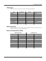
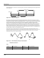
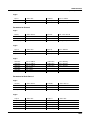
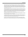
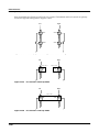
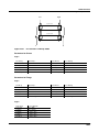
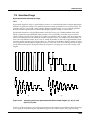
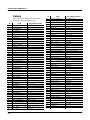
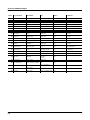
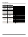
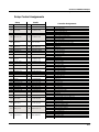
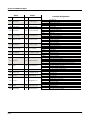
LFOs
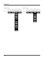
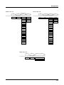
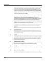
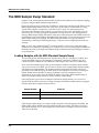
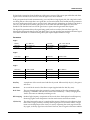
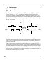
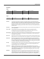
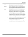
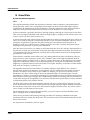
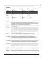
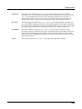
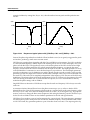
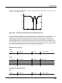
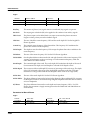
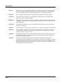
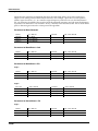
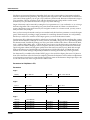
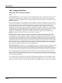
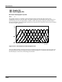
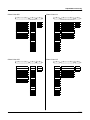
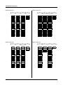
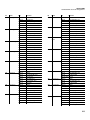
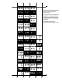
LFO Shapes
Chapter 2
LFOs
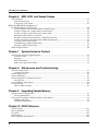
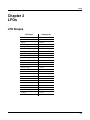
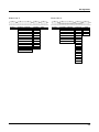
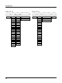
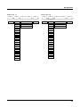
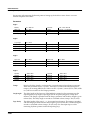
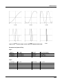
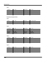
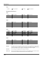
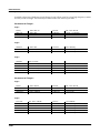
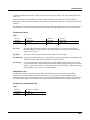
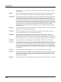
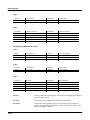
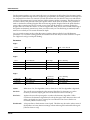
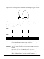
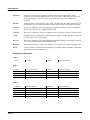
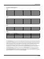
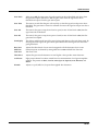
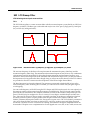
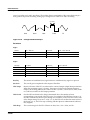
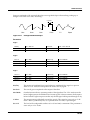
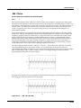
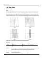
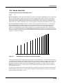
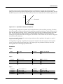
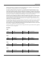
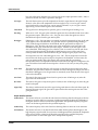
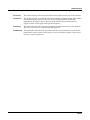
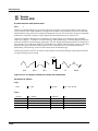
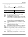
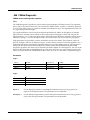
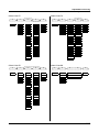
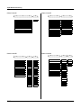
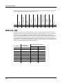
LFO Shapes
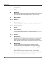
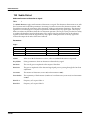
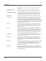
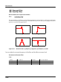
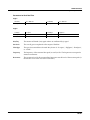
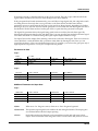
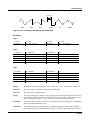
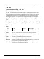
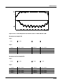
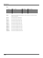
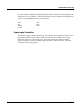
LFO Shape
Displayed As
Sine
Sine
Positive Sine
+Sine
Square
Square
Positive Square
+Squar
Triangle
Triang
Positive Triangle
+Trian
Rising Sawtooth
Rise S
Positive Rising Sawtooth
+Rise
Falling Sawtooth
Fall S
Positive Falling Sawtooth
+Fall
3 Step
3 Step
Positive 3 Step
+3 Ste
4 Step
4 Step
Positive 4 step
+4 Ste
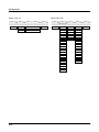
5 Step
5 Step
Positive 5 Step
+5 Ste
6 Step
6 Step
Positive 6 Step
+6 Ste
7 Step
7 Step
Positive 7 Step
+7 Ste
8 Step
8 Step
Positive 8 Step
+8 Ste
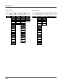
10 Step
10 Ste
Positive 10 Step
+10 St
12 Step
12 Ste
Positive 12 Step
+12 St
2-1
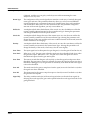
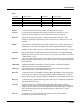
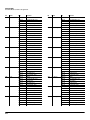
LFOs
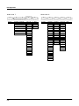
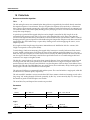
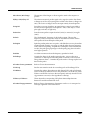
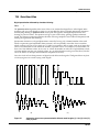
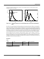
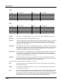
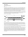
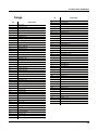
LFO Shapes
Positive Sine
Sine
+1
+1
-1
0°
270°
180°
0°
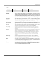
Triangle
180°
360° / 0°
0°
270°
180°
360° / 0°
+1
0°
180°
360° / 0°
0°
180°
360° / 0°
0°
4 Step
180°
360° / 0°
180°
360° / 0°
0°
270°
180°
90°
360° / 0°
0°
0°
360° / 0°
+1
-1
90°
360° / 0°
270°
180°
Positive 5 Step
-1
180°
360° / 0°
-1
0°
270°
270°
180°
Positive 3 Step
+1
90°
0°
5 Step
-1
270°
90°
360° / 0°
+1
90°
+1
-1
180°
3 Step
Positive 4 Step
+1
90°
0°
270°
360° / 0°
-1
-1
90°
270°
180°
Positive Rising Sawtooth
270°
+1
-1
0°
+1
90°
Positive Falling Sawtooth
270°
90°
360° / 0°
Rising Sawtooth
270°
+1
-1
180°
-1
90°
Falling Sawtooth
90°
0°
270°
+1
-1
90°
-1
90°
+1
-1
2-2
270°
Positive Triangle
+1
+1
-1
90°
360° / 0°
Positive Sq uare
+1
-1
90°
0°
Sq uare
270°
180°
90°
360° / 0°
0°
270°
180°
360° / 0°
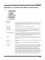
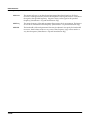
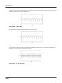
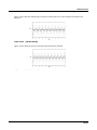
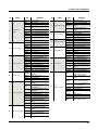
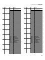
LFOs
LFO Shapes
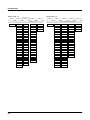
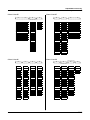
6 Step
+1
-1
0°
270°
180°
0°
8 Step
270°
180°
360° / 0°
270°
180°
0°
270°
180°
0°
360° / 0°
270°
180°
360° / 0°
Positive 10 Step
+1
-1
90°
0°
12 Step
270°
180°
90°
360° / 0°
0°
270°
180°
360° / 0°
Positive 12 Step
+1
+1
-1
-1
90°
0°
90°
360° / 0°
-1
90°
360° / 0°
180°
+1
-1
90°
0°
270°
10 Step
+1
-1
-1
90°
Positive 8 Step
+1
+1
-1
90°
360° / 0°
Positive 7 Step
+1
-1
90°
0°
7 Step
6 Step
Positive Sine
+1
270°
180°
90°
360° / 0°
0°
270°
180°
360° / 0°
2-3
LFOs
LFO Shapes
2-4
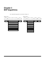
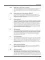
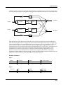
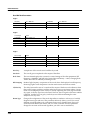
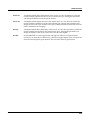
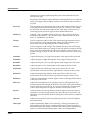
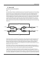
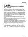
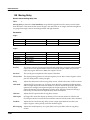
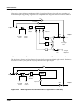
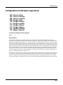
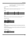
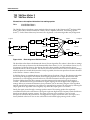
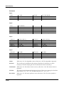
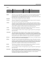
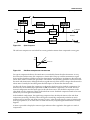
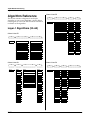
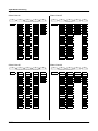
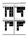
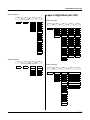
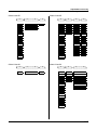
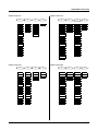
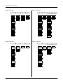
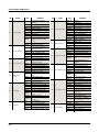
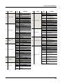
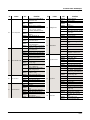
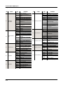
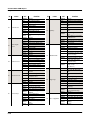
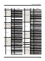
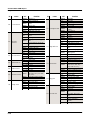
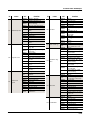
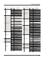
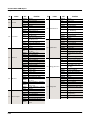
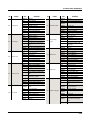
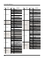
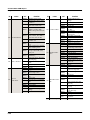
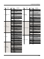
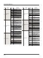
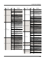
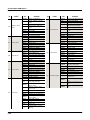
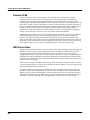
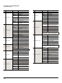
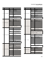
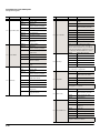
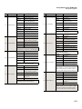
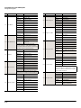
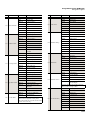
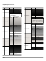
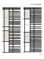
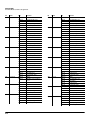
Chapter 3
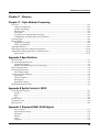
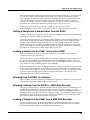
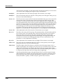
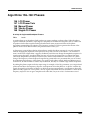
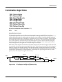
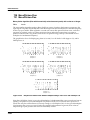
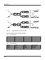
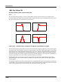
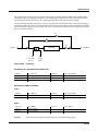
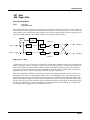
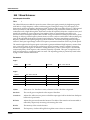
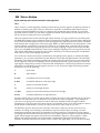
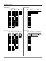
DSP Algorithms
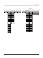
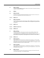
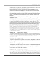
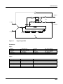
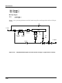
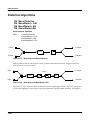
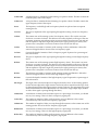
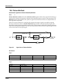
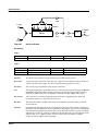
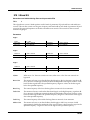
Note: Triple Mode algorithms are described in Chapter 12.
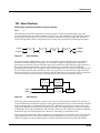
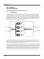
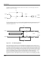
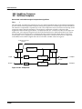
Algorithm|1||||||||||||||||||||||||||||||
|||||||||||||||||||||||||||||||||||||||||
errR®rrterrR®rrrrrrR®rrrrrrR®rrterrR®rrt|
d||||||gk||||||||||||||||||||||gk||||||gh
cvvvvvvbcvvvvvvvvvvvvvvvvvvvvvvbcvvvvvvb|
PITCH
HIFREQ STIMULATOR
AMP
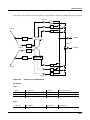
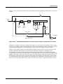
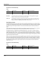
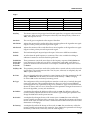
Algorithm|2||||||||||||||||||||||||||||||
|||||||||||||||||||||||||||||||||||||||||
errR®rrterrR®rrrrrrR®rrterrR®rrtYrrR®rrty
d||||||gk||||||||||||||gk||||||G;||||||GH
cvvvvvvbcvvvvvvvvvvvvvvbcvvvvvvbNvvvvvvbn
PITCH
2PARAM SHAPER
PARAMETRIC EQ
2POLE LOWPASS
STEEP RESONANT BASS
BANDPASS FILT
4POLE LOPASS W/SEP
NOTCH FILTER
4POLE HIPASS W/SEP
2POLE ALLPASS
TWIN PEAKS BANDPASS
PARA BASS
DOUBLE NOTCH W/SEP
PARA TREBLE
NONE
PARA MID
NONE
PANNER
AMP
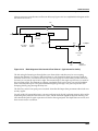
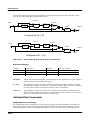
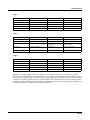
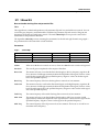
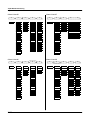
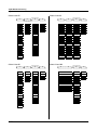
DSP Algorithms
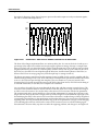
Algorithm|3||||||||||||||||||||||||||||||
|||||||||||||||||||||||||||||||||||||||||
errR®rrterrR®rrrrrrR®rrtyrrR®rrrrrrR®rrty
d||||||jk||||||||||||||u:||||||||||||||GH
cvvvvvvm,..............M/vvvvvvvvvvvvvvbn
PITCH
2PARAM SHAPER
AMP U
AMP L
2POLE LOWPASS
BAL
AMP
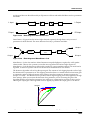
Algorithm|4||||||||||||||||||||||||||||||
|||||||||||||||||||||||||||||||||||||||||
errR®rrterrR®rrrrrrR®rrterrR®rrterrR®rrt|
d||||||gk||||||||||||||gk||||||gk||||||gh
cvvvvvvbcvvvvvvvvvvvvvvbcvvvvvvbcvvvvvvb|
PITCH
2PARAM SHAPER
LPCLIP
2POLE LOWPASS
SINE+
BANDPASS FILT
BANDPASS FILT
NOISE+
NOTCH FILTER
NOTCH FILTER
LOPASS
2POLE ALLPASS
2POLE ALLPASS
HIPASS
NONE
PARA BASS
ALPASS
PARA TREBLE
GAIN
PARA MID
SHAPER
NONE
DIST
SW+SHP
SAW+
SW+DST
NONE
3-2
AMP
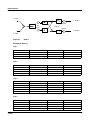
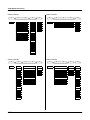
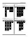
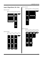
DSP Algorithms
Algorithm|5||||||||||||||||||||||||||||||
|||||||||||||||||||||||||||||||||||||||||
errR®rrterrR®rrrrrrR®rrterrR®rrterrR®rrt|
d||||||gk||||||||||||||gk||||||gk||||||gh
cvvvvvvbcvvvvvvvvvvvvvvbcvvvvvvbcvvvvvvb|
PITCH
2PARAM SHAPER
LP2RES
2POLE LOWPASS
2PARAM SHAPER
LPCLIP
x AMP
SHAPE2
2POLE LOWPASS
SINE+
+ AMP
BANDPASS FILT
BAND2
BANDPASS FILT
NOISE+
! AMP
NOTCH FILTER
NOTCH2
NOTCH FILTER
LOPASS
2POLE ALLPASS
LOPAS2
2POLE ALLPASS
HIPASS
PARA BASS
HIPAS2
NONE
ALPASS
PARA TREBLE
LPGATE
GAIN
PARA MID
NONE
SHAPER
NONE
AMP
Algorithm|6||||||||||||||||||||||||||||||
|||||||||||||||||||||||||||||||||||||||||
errR®rrterrR®rrrrrrR®rrterrR®rrtYrrR®rrt|
d||||||jk||||||||||||||gk||||||u:||||||gh
cvvvvvvm,..............M,......M/vvvvvvb|
PITCH
DIST
SW+SHP
SAW+
SW+DST
NONE
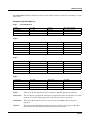
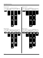
3-3
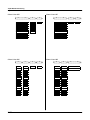
DSP Algorithms
Algorithm|7||||||||||||||||||||||||||||||
|||||||||||||||||||||||5rrrrrrrr6||||||||
errR®rrterrR®rrrrrrR®rrTerrR®rrt7rrR®rrt|
d||||||jk||||||||||||||u?||||||i;||||||gh
cvvvvvvm,..............M/vvvvvvbNvvvvvvb|
PITCH
2PARAM SHAPER
LPCLIP
x AMP
2POLE LOWPASS
SINE+
BANDPASS FILT
NOISE+
NOTCH FILTER
Algorithm|8||||||||||||||||||||||||||||||
|||||||||||||||||||||||||||||||||||||||||
errR®rrterrR®rrterrR®rrterrR®rrterrR®rrt|
d||||||gk||||||gk||||||gk||||||gk||||||gh
cvvvvvvbcvvvvvvbcvvvvvvbcvvvvvvbcvvvvvvb|
LOPASS
LOPASS
LPCLIP
+ AMP
HIPASS
HIPASS
SINE+
! AMP
ALPASS
ALPASS
NOISE+
LOPASS
GAIN
GAIN
LOPASS
2POLE ALLPASS
HIPASS
SHAPER
SHAPER
HIPASS
NONE
ALPASS
DIST
DIST
ALPASS
GAIN
PWM
SW+SHP
GAIN
SHAPER
SINE
SAW+
SHAPER
DIST
LF SIN
WRAP
DIST
SINE
SW+SHP
NONE
SW+SHP
LF SIN
SAW+
SAW+
SW+SHP
SAW
SW+DST
SAW+
LF SAW
NONE
SW+DST
SQUARE
NONE
LF SQR
PITCH
WRAP
NONE
3-4
AMP
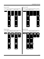
DSP Algorithms
Algorithm|9||||||||||||||||||||||||||||||
|||||||||||||||||||||||||||||||||||||||||
errR®rrterrR®rrterrR®rrterrR®rrterrR®rrt|
d||||||gk||||||gk||||||gk||||||gk||||||gh
cvvvvvvbcvvvvvvbcvvvvvvbcvvvvvvbcvvvvvvb|
PITCH
LOPASS
LOPASS
LP2RES
HIPASS
HIPASS
ALPASS
Algorithm|10|||||||||||||||||||||||||||||
|||||||||||||||5rrrrrrrr6||||||||||||||||
errR®rrterrR®rrTerrR®rrt7rrR®rrtYrrR®rrt|
d||||||jk||||||u?||||||JU||||||u:||||||gh
cvvvvvvm,......M/vvvvvvm,......M/vvvvvvb|
LOPASS
LOPASS
LPCLIP
x AMP
SHAPE2
HIPASS
HIPASS
SINE+
+ AMP
ALPASS
BAND2
ALPASS
ALPASS
NOISE+
! AMP
GAIN
GAIN
NOTCH2
GAIN
GAIN
LOPASS
SHAPER
SHAPER
LOPAS2
SHAPER
SHAPER
HIPASS
DIST
DIST
HIPAS2
DIST
DIST
ALPASS
PWM
SW+SHP
LPGATE
PWM
SINE
GAIN
SINE
SAW+
NONE
SINE
LF SIN
SHAPER
LF SIN
WRAP
LF SIN
SW+SHP
DIST
SW+SHP
NONE
SW+SHP
SAW+
SW+SHP
SAW+
SAW+
SAW
SAW+
SAW
SAW
LF SAW
SW+DST
LF SAW
LF SAW
SQUARE
NONE
SQUARE
SQUARE
LF SQR
LF SQR
LF SQR
WRAP
WRAP
WRAP
NONE
NONE
NONE
AMP
PITCH
3-5
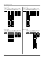
DSP Algorithms
Algorithm|11|||||||||||||||||||||||||||||
|||||||||||||||5rrrrrrrr6||||||||||||||||
errR®rrterrR®rrTerrR®rrt7rrR®rrtYrrR®rrt|
d||||||gk||||||fk||||||jU||||||u:||||||gh
cvvvvvvbcvvvvvvbcvvvvvvm,......M/vvvvvvb|
PITCH
LOPASS
LOPASS
LPCLIP
x AMP
HIPASS
HIPASS
SINE+
ALPASS
ALPASS
NOISE+
GAIN
GAIN
SHAPER
LOPASS
LOPASS
LPCLIP
x AMP
+ AMP
HIPASS
HIPASS
SINE+
+ AMP
! AMP
ALPASS
ALPASS
NOISE+
! AMP
LOPASS
GAIN
GAIN
LOPASS
SHAPER
HIPASS
SHAPER
SHAPER
HIPASS
DIST
DIST
ALPASS
DIST
DIST
ALPASS
PWM
SINE
GAIN
PWM
PWM
GAIN
SINE
LF SIN
SHAPER
SINE
SINE
SHAPER
LF SIN
SW+SHP
DIST
LF SIN
LF SIN
DIST
SW+SHP
SAW+
SINE
SW+SHP
SW+SHP
SW+SHP
SAW+
SAW
LF SIN
SAW+
SAW+
SAW+
SAW
LF SAW
SW+SHP
SAW
SAW
SW+DST
LF SAW
SQUARE
SAW+
LF SAW
LF SAW
NONE
SQUARE
LF SQR
SW+DST
SQUARE
SQUARE
LF SQR
WRAP
NONE
LF SQR
LF SQR
WRAP
NONE
WRAP
WRAP
NONE
NONE
NONE
3-6
Algorithm|12|||||||||||||||||||||||||||||
|||||||||||||||||||||||||||||||||||||||||
errR®rrterrR®rrterrR®rrterrR®rrtYrrR®rrt|
d||||||gk||||||jk||||||gk||||||u:||||||gh
cvvvvvvbcvvvvvvm,......M,......M/vvvvvvb|
PITCH
DSP Algorithms
Algorithm|13|||||||||||||||||||||||||||||
|||||||||||||||||||||||||||||||||||||||||
errR®rrterrR®rrterrR®rrterrR®rrtYrrR®rrty
d||||||gk||||||gk||||||gk||||||G;||||||GH
cvvvvvvbcvvvvvvbcvvvvvvbcvvvvvvbNvvvvvvbn
PITCH
LOPASS
LOPASS
HIPASS
PANNER
AMP
Algorithm|14|||||||||||||||||||||||||||||
|||||||||||||||5rrrrrrrr6||||||||||||||||
errR®rrterrR®rrTerrR®rrt7rrR®rrrrrrR®rrty
d||||||jk||||||u?||||||i;||||||||||||||GH
cvvvvvvm,......M/vvvvvvbNvvvvvvvvvvvvvvbn
PITCH
LOPASS
LOPASS
AMP U
AMP L
HIPASS
HIPASS
HIPASS
BAL
AMP
ALPASS
ALPASS
ALPASS
ALPASS
GAIN
GAIN
GAIN
GAIN
SHAPER
SHAPER
SHAPER
SHAPER
DIST
DIST
DIST
DIST
PWM
SW+SHP
SINE
SINE
SINE
SAW+
LF SIN
LF SIN
LF SIN
WRAP
SW+SHP
SW+SHP
SW+SHP
NONE
SAW+
SAW+
SAW+
SAW
SAW
SAW
LF SAW
LF SAW
LF SAW
SQUARE
SQUARE
SQUARE
LF SQR
LF SQR
LF SQR
WRAP
WRAP
WRAP
NONE
NONE
NONE
3-7
DSP Algorithms
Algorithm|15|||||||||||||||||||||||||||||
|||||||||||||||||||||||||||||||||||||||||
errR®rrterrR®rrterrR®rrtYrrR®rrrrrrR®rrty
d||||||gk||||||jk||||||u:||||||||||||||GH
cvvvvvvbcvvvvvvm,......M/vvvvvvvvvvvvvvbn
PITCH
LOPASS
LOPASS
AMP U
AMP L
HIPASS
HIPASS
BAL
AMP
ALPASS
PITCH
LOPASS
PARA BASS
HIPASS
PARA TREBLE
ALPASS
ALPASS
NONE
GAIN
GAIN
GAIN
SHAPER
SHAPER
SHAPER
DIST
DIST
DIST
PWM
SINE
SINE
SINE
LF SIN
LF SIN
LF SIN
SW+SHP
SW+SHP
SW+SHP
SAW+
SAW+
SAW+
SAW
SAW
SAW
LF SAW
LF SAW
LF SAW
SQUARE
SQUARE
SQUARE
LF SQR
LF SQR
LF SQR
WRAP
WRAP
WRAP
NONE
NONE
NONE
3-8
Algorithm|16|||||||||||||||||||||||||||||
|||||||||||||||||||||||||||||||||||||||||
errR®rrterrR®rrterrR®rrrrrrR®rrterrR®rrt|
d||||||gk||||||gk||||||||||||||gk||||||gh
cvvvvvvbcvvvvvvbcvvvvvvvvvvvvvvbcvvvvvvb|
AMP
DSP Algorithms
Algorithm|17|||||||||||||||||||||||||||||
|||||||||||||||||||||||||||||||||||||||||
errR®rrterrR®rrterrR®rrrrrrR®rrterrR®rrt|
d||||||gk||||||gk||||||||||||||gk||||||gh
cvvvvvvbcvvvvvvbcvvvvvvvvvvvvvvbcvvvvvvb|
PITCH
LOPASS
SHAPE MOD OSC
HIPASS
ALPASS
AMP
Algorithm|18|||||||||||||||||||||||||||||
|||||||||||||||||||||||||||||||||||||||||
errR®rrterrR®rrtYrrR®rrrrrrR®rrterrR®rrt|
d||||||jk||||||u:||||||||||||||gk||||||gh
cvvvvvvm,......M/vvvvvvvvvvvvvvbcvvvvvvb|
PITCH
LOPASS
x SHAPEMOD OSC
AMP MOD OSC
HIPASS
+ SHAPEMOD OSC
NONE
ALPASS
NONE
GAIN
GAIN
SHAPER
SHAPER
DIST
DIST
PWM
SINE
SINE
LF SIN
LF SIN
SW+SHP
SW+SHP
SAW+
SAW+
SAW
SAW
LF SAW
LF SAW
SQUARE
SQUARE
LF SQR
LF SQR
WRAP
WRAP
NONE
AMP
NONE
3-9
DSP Algorithms
Algorithm|19|||||||||||||||||||||||||||||
|||||||||||||||||||||||||||||||||||||||||
errR®rrterrR®rrterrR®rrrrrrR®rrterrR®rrt|
d||||||gk||||||gk||||||||||||||gk||||||gh
cvvvvvvbcvvvvvvbcvvvvvvvvvvvvvvbcvvvvvvb|
PITCH
LOPAS2
SHAPE MOD OSC
NONE
NONE
AMP
Algorithm|20|||||||||||||||||||||||||||||
|||||||||||||||||||||||||||||||||||||||||
errR®rrterrR®rrtYrrR®rrterrR®rrterrR®rrt|
d||||||jk||||||u:||||||gk||||||gk||||||gh
cvvvvvvm,......M/vvvvvvbcvvvvvvbcvvvvvvb|
PITCH
LOPASS
x GAIN
LPCLIP
HIPASS
+ GAIN
SINE+
ALPASS
XFADE
NOISE+
GAIN
AMPMOD
LOPASS
SHAPER
NONE
HIPASS
DIST
ALPASS
SINE
GAIN
LF SIN
SHAPER
SW+SHP
DIST
SAW+
SW+SHP
SAW
SAW+
LF SAW
SW+DST
SQUARE
NONE
LF SQR
WRAP
NONE
3-10
AMP
DSP Algorithms
Algorithm|21|||||||||||||||||||||||||||||
|||||||||||||||||||||||||||||||||||||||||
errR®rrterrR®rrtYrrR®rrterrR®rrterrR®rrt|
d||||||jk||||||u:||||||gk||||||gk||||||gh
cvvvvvvm,......M/vvvvvvbcvvvvvvbcvvvvvvb|
PITCH
Algorithm|22|||||||||||||||||||||||||||||
|||||||||||||||5rrrrrrrr6||||||||||||||||
errR®rrterrR®rrTYrrR®rrt7rrR®rrtYrrR®rrt|
d||||||jk||||||u:||||||JU||||||u:||||||gh
cvvvvvvm,......M/vvvvvvm,......M/vvvvvvb|
LOPASS
x GAIN
LPCLIP
x AMP
SHAPE2
HIPASS
+ GAIN
SINE+
+ AMP
XFADE
BAND2
ALPASS
XFADE
NOISE+
! AMP
GAIN
AMPMOD
NOTCH2
GAIN
AMPMOD
LOPASS
SHAPER
NONE
LOPAS2
SHAPER
NONE
HIPASS
DIST
HIPAS2
DIST
ALPASS
SINE
LPGATE
SINE
GAIN
LF SIN
NONE
LF SIN
SHAPER
SW+SHP
SW+SHP
DIST
SAW+
SAW+
SINE
SAW
SAW
LF SIN
LF SAW
LF SAW
SW+SHP
SQUARE
SQUARE
SAW+
LF SQR
LF SQR
SW+DST
WRAP
WRAP
NONE
NONE
NONE
LOPASS
x GAIN
LP2RES
HIPASS
+ GAIN
ALPASS
AMP
PITCH
3-11
DSP Algorithms
Algorithm|23|||||||||||||||||||||||||||||
|||||||||||||||||||||||||||||||||||||||||
errR®rrterrR®rrtYrrR®rrterrR®rrtYrrR®rrt|
d||||||jk||||||u:||||||jk||||||u:||||||gh
cvvvvvvm,......M/vvvvvvm,......M/vvvvvvb|
PITCH
LOPASS
x GAIN
LPCLIP
x AMP
HIPASS
+ GAIN
SINE+
ALPASS
XFADE
NOISE+
GAIN
AMPMOD
SHAPER
NONE
LOPASS
x GAIN
+ AMP
HIPASS
+ GAIN
! AMP
ALPASS
XFADE
LOPASS
GAIN
AMPMOD
HIPASS
SHAPER
NONE
DIST
ALPASS
DIST
SINE
GAIN
SINE
LF SIN
SHAPER
LF SIN
SW+SHP
DIST
SW+SHP
SAW+
SINE
SAW+
SAW
LF SIN
SAW
LF SAW
SW+SHP
LF SAW
SQUARE
SAW+
SQUARE
LF SQR
SW+DST
LF SQR
WRAP
NONE
WRAP
NONE
3-12
Algorithm|24|||||||||||||||||||||||||||||
|||||||||||||||||||||||||||||||||||||||||
errR®rrterrR®rrtYrrR®rrterrR®rrtYrrR®rrty
d||||||jk||||||u:||||||gk||||||G;||||||GH
cvvvvvvm,......M/vvvvvvbcvvvvvvbNvvvvvvbn
PITCH
NONE
PANNER
AMP
DSP Algorithms
Algorithm|25|||||||||||||||||||||||||||||
|||||||||||||||5rrrrrrrr6||||||||||||||||
errR®rrterrR®rrTYrrR®rrt7rrR®rrrrrrR®rrty
d||||||jk||||||u:||||||i;||||||||||||||GH
cvvvvvvm,......M/vvvvvvbNvvvvvvvvvvvvvvbn
PITCH
LOPASS
x GAIN
AMP U
AMP L
HIPASS
+ GAIN
BAL
AMP
ALPASS
XFADE
GAIN
AMPMOD
SHAPER
NONE
Algorithm|26|||||||||||||||||||||||||||||
|||||||||||||||||||||||||||||||||||||||||
||||||||errR®rrterrR®rrterrR®rrtYrrR®rrty
||||||||d||||||©d||||||gk||||||G;||||||GH
||||||||cvvvvvvbcvvvvvvbcvvvvvvbNvvvvvvbn
SYNC M
SYNC S
PANNER
AMP
DIST
SINE
LF SIN
SW+SHP
SAW+
SAW
LF SAW
SQUARE
LF SQR
WRAP
NONE
3-13
DSP Algorithms
Algorithm|27|||||||||||||||||||||||||||||
|||||||||||||||||||||||||||||||||||||||||
||||||||errR®rrterrR®rrterrR®rrterrR®rrt|
||||||||d||||||©d||||||gk||||||gk||||||gh
||||||||cvvvvvvbcvvvvvvbcvvvvvvbcvvvvvvb|
SYNC M
SYNC S
LPCLIP
SYNC M
SYNC S
LP2RES
SINE+
SHAPE2
NOISE+
BAND2
LOPASS
NOTCH2
HIPASS
LOPAS2
ALPASS
HIPAS2
GAIN
LPGATE
SHAPER
NONE
DIST
SINE
LF SIN
SW+SHP
SAW+
SW+DST
NONE
3-14
AMP
Algorithm|28|||||||||||||||||||||||||||||
|||||||||||||||||||||||||||||||||||||||||
||||||||errR®rrterrR®rrterrR®rrterrR®rrt|
||||||||d||||||©d||||||gk||||||gk||||||gh
||||||||cvvvvvvbcvvvvvvbcvvvvvvbcvvvvvvb|
AMP
DSP Algorithms
Algorithm|29|||||||||||||||||||||||||||||
|||||||||||||||||||||||5rrrrrrrr6||||||||
||||||||errR®rrterrR®rrTerrR®rrt7rrR®rrt|
||||||||d||||||jd||||||u?||||||i;||||||gh
||||||||cvvvvvvm,......M/vvvvvvbNvvvvvvb|
SYNC M
SYNC S
LPCLIP
x AMP
SINE+
NOISE+
Algorithm|30|||||||||||||||||||||||||||||
|||||||||||||||||||||||||||||||||||||||||
||||||||errR®rrterrR®rrtYrrR®rrtYrrR®rrt|
||||||||d||||||jd||||||G;||||||u:||||||gh
||||||||cvvvvvvm,......ML......M/vvvvvvb|
SYNC M
SYNC S
LPCLIP
x AMP
+ AMP
SINE+
+ AMP
! AMP
NOISE+
! AMP
LOPASS
LOPASS
HIPASS
HIPASS
ALPASS
ALPASS
GAIN
GAIN
SHAPER
SHAPER
DIST
DIST
SINE
SINE
LF SIN
LF SIN
SW+SHP
SW+SHP
SAW+
SAW+
SW+DST
SW+DST
NONE
NONE
Algorithm|31|||||||||||||||||||||||||||||
|||||||||||||||||||||||||||||||||||||||||
||||||||errR®rrterrR®rrtYrrR®rrrrrrR®rrty
||||||||d||||||jd||||||u:||||||||||||||GH
||||||||cvvvvvvm,......M/vvvvvvvvvvvvvvbn
SYNC M
SYNC S
AMP U
AMP L
BAL
AMP
3-15
DSP Algorithms
3-16
Control Sources
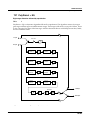
Chapter 4
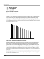
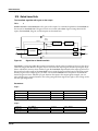
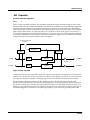
Control Sources
Control sources are assigned as values for control source parameters, like Src1 and Src2, Depth
Control for Src2, and LFO rate control. Assigning a control source to one of these parameters is
like connecting control source outputs to various inputs on early modular synthesizers. You can
think of each control source parameter as the input to a synthesizer module, and the values for
those parameters as the outputs of modules generating control signals.
For the control sources to have an effect, two things have to happen. First, the control source
must be assigned as the value for (patched to) a control source parameter like Src1. In other
words, for a control source parameter to have an effect, it must be programmed to respond to a
particular control message. Second, the control source must generate a signal. The level of the
control source’s signal determines how much effect it has on the control source parameter to
which it’s assigned.
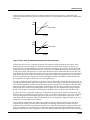
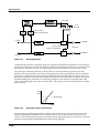
In terms of generating signals, there are two types of control sources. The first, which might be
called hardware control sources, require some physical movement to transmit them. The control
source called MWheel (MIDI 01) is probably the most prominent example of this type of control
source. When you move your MIDI controller’s Mod Wheel, it sends a Modulation message
(MIDI 01), unless you’ve programmed it to send something else. By default, when the K2661
receives a MIDI 01 message, it responds by sending a control signal to whatever control source is
assigned as the value for the MWhl parameter on the MIDI-mode RECEIVE page. Of course,
you can program the MWhl parameter to send any available control source signal in response to
MIDI 01 messages.
Some of these hardware control sources have physical controls “hard-wired” to transmit them.
That is, there are certain physical controls that always generate these control signals. Every time
you strike one of your MIDI source’s keys (or pluck a string, or whatever), for example, a
Note On message is generated, along with an Attack Velocity message. So any time you strike a
key, any control source parameter that has AttVel assigned as its value will be affected by the
Attack Velocity message. Similarly, every time you move the physical Pitch Wheel, a PWheel
message is generated. Whether this affects anything depends on whether you have assigned any
control source parameters to respond to the PWheel message (in other words, whether any
control source parameter has PWheel assigned as its value).
In the Setup Editor you’ll find several parameters that correspond to the standard physical
controllers found on many keyboards. The values you assign for these parameters determine
which control messages will be transmitted to the K2661 and to its MIDI Out port when you
move the corresponding controls on your MIDI source. If you look at the WHEEL page in the
Setup Editor, you’ll see that the parameter called MWhl has a default value of MWheel. You can
interpret this as follows: “Moving the Mod Wheel on my MIDI source sends the MWheel
(Modulation, MIDI 01) message to the K2661’s sound engine, and, if the K2661’s LocalKbdCh
parameter matches my controller’s transmit channel, also sends it to the K2661’s MIDI Out
port.”
4-1
Control Sources
If you change the value of the MWhl parameter, the Mod Wheel will no longer send the MWheel
message, and any control source parameter with MWheel assigned as its value will no longer
respond to movement of the Mod Wheel. All of the control assignment parameters in the Setup
Editor can be programmed to send any of the MIDI controller numbers. For example, if you
assign Foot (MIDI 04) as the value for the Press parameter, then generating mono pressure
messages from your MIDI source will send a Foot (MIDI 04) message to the K2661’s sound
engine, and will affect any control source parameter that has Foot assigned as its value.
The other type of control source is independent of the movement of physical controls. These
control sources generate their control signals internally, and might be called software control
sources. They either run automatically (like A Clock and RandV1), or they’re programmed to
generate their signals according to parameters of their own (as with the LFOs and FUNs). The
software control sources must have some nonzero value set for one or more of their parameters
before they’ll generate control signals.
To summarize, there are two different cases in which you’ll assign control sources. One, the
transmit case, determines what control message will be sent by a particular physical control. For
example, MWheel is set by default to be transmitted by the Mod Wheel. The other case, the
receive case, determines which control message will activate a particular control source
parameter. For example, if you assign MPress as the value for the Src1 parameter on the PITCH
page in the Program Editor, then that layer’s pitch will be affected whenever an MPress message
is generated by any physical controller.
4-2
Control Sources
Control Source Lists
Control Source Lists
There’s one long list of control sources stored in the K2661’s memory, although not all control
sources are available for all control source parameters. With time you’ll become familiar with
the types of control sources available for various control source parameters.
The available list of control sources varies depending on the type of control source parameter
you’re programming. There are four basic types: MIDI control sources, local control sources,
global control sources, and FUNs.
When you’re setting the control assignment parameters in the Setup Editor, you’ll see only the
portion of the Control Source list that has values appropriate to MIDI controller messages.
Consequently we refer to this subset of the Main Control Source list as the MIDI Control Source
list.
You’ll see variations on the Main Control Source list as you program the other control source
parameters. We’ll explain these variations, but it’s not important that you memorize each
variation. The lists differ to prevent you from assigning a control source where it would be
ineffective. All you have to do is to scroll through the list of control sources available for any
given control source parameter, and choose from the available values.
If you’re programming one of the FUNs, you’ll see the Main Control Source list, which includes
almost every control source from the MIDI Control Source list (with the exception of Data Inc,
Data Dec, and Panic, which belong exclusively to the MIDI Control Source list). The list for the
FUNs also includes a set of constant values, that set an unvarying control signal level for one or
both of the FUN’s inputs.
For most other control source parameters, you’ll see the Main Control Source list (without the
FUN constants and the three special MIDI control sources we mentioned above). There are two
exceptions to this rule, which have to do with global control source parameters. Globals affect
every note in each program’s layer(s). Consequently they can’t use local control sources as their
values, since local control sources affect each note independently.
One control source parameters is always global: the Enable parameter on the LAYER page
(Program Editor). When programming this parameter, you’ll see the Main Control Source list
minus the three special MIDI control sources, minus the following local control sources:
Note St
VTRIG2
Key St
RandV1
KeyNum
RandV2
BKeyNum
ASR1
AttVel
LFO1
InvAVel
FUN1
PPress
FUN3
BPPress
Loop St
RelVel
PB Rate
Bi-AVel
AtkSt
VTRIG1
Rel St
Finally, if you’ve turned on the Globals parameter on the COMMON page in the Program
Editor, the available values for GLFO2, and the values for GASR2’s trigger will lack the local
control sources listed above, as well as the three special MIDI control sources and the FUN
constants. The available values for GFUN2 and GFUN4 will exclude the same list of local control
sources, but will include the FUN constants.
4-3
Control Sources
Descriptions of Control Sources
Descriptions of Control Sources
This section is organized into two sets of descriptions: the MIDI Control Source list, and the rest
of the control sources. The numeral preceding the name of each control source can be entered on
the alphanumeric pad to select the control source directly (press Enter after typing the numeral).
Many of the MIDI control sources are assigned as default values for the control assignment
parameters in the Setup Editor. We’ll indicate these assignments as they appear, simply by
mentioning that they’re the default control source for a control assignment parameter.
4-4
Control Sources
MIDI Control Source List
MIDI Control Source List
With a few exceptions, the MIDI control sources correspond to the standard MIDI controller
numbers used by every MIDI device.
128
OFF
This value eliminates the effect of any control source parameter to which it’s
assigned.
0, 33
Mono Pressure (MPress)
Many of the K2661’s factory programs are assigned to modify parameters such as
pitch, filter cutoff frequency, and depth control when MPress messages are received.
The mono pressure (Press) control assignment parameters in MIDI and Setup
modes are set by default to transmit MPress messages when mono pressure
messages are received from a controller.
1
MIDI 01 (MWheel)
Many factory programs are assigned to respond to MWheel messages. The MWhl
parameter in the Setup Editor is set by default to transmit MWheel.
2
MIDI 02 (Breath)
3
MIDI 03
4
MIDI 04 (Foot)
This is the standard MIDI Controller number for continuous control foot pedals. It’s
the default value for the CPedal control assignment parameter, so a control pedal on
your MIDI controller which sends MIDI controller 04 messages will send MIDI
controller 04 messages to the K2661 by default.
5
MIDI 05 (PortTim)
This is the standard MIDI controller number for portamento time control. The
K2661 always responds to this control message. For any program that has
portamento turned on (on the COMMON page in the Program Editor), MIDI
Portamento Time messages received via MIDI will affect the rate of the program’s
portamento.
6
MIDI 06 (Data)
MIDI 06 is the standard MIDI controller number for data entry. The Slider A
parameter on the SLIDER page in the Setup Editor is set by default to transmit this
message, and can be used to select programs and edit parameters on MIDI slaves if
your controller can send it.
7
MIDI 07 (Volume)
This is the standard MIDI controller number for volume. The Volume parameter on
the CHANNELS page in MIDI mode will respond to MIDI controller 07 unless the
VolLock parameter is turned on.
4-5
Control Sources
MIDI Control Source List
4-6
8
MIDI 08 (Balance)
9
MIDI 09
10
MIDI 10 (Pan)
MIDI controller 10 is defined as Pan control. The Pan parameter on the CHANNELS
page in MIDI mode will respond to MIDI controller 10 unless the PanLock
parameter is turned on.
11
MIDI 11 (Express)
12—14
MIDI 12—14
15
MIDI 15 (AuxBend2)
The K2661 interprets MIDI Controller 15 as AuxBend2. A value of 64 is centered.
16—19
MIDI 16—19 (Ctl A—D)
20
MIDI 20
21
MIDI 21 (AuxBend1)
The K2661 interprets MIDI Controller 21 as AuxBend1, which is assigned by default
to the long ribbon (above the keyboard). A value of 64 is centered.
22—31
MIDI 22—31
64
MIDI 64 (Sustain)
This is the standard MIDI Controller number for Sustain. The control assignment
parameter FtSw1 is set by default to MIDI Controller 64, so a switch pedal on your
MIDI controller that sends MIDI 64 will send sustain messages to the K2661 by
default. The K2661 will always respond to sustain messages by sustaining currently
active notes.
65
MIDI 65 (PortSw)
This is the standard MIDI Controller number for Portamento Switch. The
Portamento parameter on the COMMON page in the Program Editor always
responds to this controller, and will turn Portamento on for monophonic programs
when the controller signal is at 64 or above. It won’t affect polyphonic programs.
66
MIDI 66 (SostPD)
MIDI Controller 66 is defined as Sostenuto Switch. The control assignment
parameter FtSw2 is set by default to MIDI Controller 66, so a switch pedal on your
MIDI controller that sends MIDI 66 will send sostenuto messages to the K2661 by
default. The K2661 will always respond to sostenuto messages.
Control Sources
MIDI Control Source List
67
MIDI 67 (SoftPd)
This is the standard MIDI Controller number for Soft Pedal. The K2661 will always
respond to Soft pedal messages.
68
MIDI 68
69
MIDI 69 (FrezPd)
The K2661 will always respond to this message. It causes all notes to be frozen at
their current amplitude levels while the function is on.
70—74
MIDI 70—74
75
MIDI 75 (LegatoSw)
The K2661 always responds to this message. When a MIDI Controller 75 message
with a value above 64 is received, the K2661 will force polyphonic programs to be
monophonic.
76—79
MIDI 76—79
80—83
MIDI 80—83 (Ctl E—H)
84—90
MIDI 84—90
91
MIDI 91 (FXDep)
The MIDI specification defines this Controller as External Effects Depth. If the
FX Mode parameter is set to Master, and the FX Channel parameter is set to a
specific MIDI channel, the K2661 will respond to this message when it is received on
the FX channel. It responds by adjusting the Wet/Dry mix of the current studio.
92—95
MIDI 92—95
96
MIDI 96 (DataInc)
This is defined as Data Increment. It’s intended to be assigned to a switch control.
When the control is on (value 127), the currently selected parameter’s value will be
increased by one increment. This could be assigned to FtSw2, for example, to scroll
through the program list while in Program mode.
97
MIDI 97 (DataDec)
This is defined as Data Decrement. It’s intended to be assigned to a switch control.
When the control is on (value 127), the currently selected parameter’s value will be
decreased by one increment.
123
MIDI 123 (Panic)
The K2661 always responds to this message by sending an All Notes Off and All
Controllers Off message on all 16 MIDI channels.
4-7
Control Sources
Main Control Source List
Main Control Source List
This list contains all but the last three control sources in the MIDI Control Source list. It also
contains the following control sources. All are local unless specified as global.
32
Channel State (Chan St)
Chan St refers to whether any notes are currently active on a given MIDI channel.
Chan St switches on whenever a note is started, and switches off when a Note Off
has been received for each current note on that channel, even if notes are sustained.
33
Mono Pressure (MPress)
This is the same as the MPress control source in the MIDI Control Source list, but is
assigned by entering 33 on the alphanumeric pad when used with a parameter that
takes its values from the Main Control Source list.
34
Bipolar Mono Pressure (BMPress)
This control source generates a control signal of -1 when the value of the control to
which it’s assigned is at its minimum, and +1 when the control is at its maximum.
For example, if you had the MPress control assignment parameter assigned to send
BMPress, and you had Src1 on a program layer’s PITCH page assigned to BMPress,
with its depth parameter set to 1200 cents, then the layer would be transposed
down an octave when no pressure (value 0) was applied to your controller’s keys
(assuming it sends mono pressure). Maximum pressure (value 127) would
transpose the layer up an octave, while a pressure level of 64 would leave the pitch
unchanged.
35
Pitch Wheel Message (PWheel)
The K2661 is hard-wired to respond to this message. Any parameter with PWheel
assigned as its value will be affected when your MIDI controller’s Pitch Wheel is
moved.
36
Bipolar Mod Wheel (Bi-Mwl)
This control source will always respond to MIDI controller 01 (MWheel). Control
source parameters set to this value will generate control signals of -1 when the MIDI
Controller 01 message value is 0, and will generate a control signal of +1 when the
MIDI Controller 01 message is at 127, scaling all values in between. For example,
you might set Src1 on a program layer’s PITCH page to a value of Bi-Mwl, and its
depth parameter to 1200 cents. Then as long as the MWhl control assignment
parameter is set to a value of MWheel, your controller’s Mod Wheel will be bipolar;
in this case it will bend the layer’s pitch down as you move the Mod Wheel toward
minimum, and bend the pitch up as you move the Mod Wheel toward maximum.
37
Absolute Value of Pitch Wheel (AbsPwl)
This control source always responds to movement of your MIDI controller’s Pitch
Wheel, but makes the Pitch Wheel unipolar. Whereas pulling the Pitch Wheel fully
down usually generates a control signal value of -1, this control source generates a
value of +1 when the Pitch Wheel is pulled fully down.
4-8
Control Sources
Main Control Source List
38
Global ASR (GASR2)
When the Globals parameter on the COMMON page is turned on, ASR2 becomes
global, and is labeled GASR2. The functions of ASRs are explained in Chapter 6 of
the Musician’s Guide. This control source does not appear in the Control Source list
for parameters whose functions are local.
39
Global FUN2 (GFUN2)
When the Globals parameter on the COMMON page is turned on, FUN2 becomes
global, and is labeled GFUN2. The functions of FUNs are explained in Chapter 17 of
the Musician’s Guide. This control source does not appear in the Control Source list
for parameters whose functions are local.
40
Global LFO (GLFO2)
When the Globals parameter on the COMMON page is turned on, LFO2 becomes
global, and is labeled GLFO2. The functions of LFOs are explained in Chapter 6 of
the Musician’s Guide. This control source does not appear in the Control Source list
for parameters whose functions are local.
41
Global LFO Phase (GLFO2ph)
When the Globals parameter on the COMMON page is turned on, LFO2 becomes
global, and is labeled GLFO2. The functions of LFOs are explained in the Musician’s
Guide. This control source does not appear in the Control Source list for parameters
whose functions are local.
42
Global FUN 4 (GFUN4)
When the Globals parameter on the COMMON page is turned on, FUN 4 becomes
global, and is labeled GFUN4. This control source does not appear in the Control
Source list for parameters whose functions are local.
43
Volume Control (VolCtl)
This control source will always respond to MIDI Controller 07 messages. Assign this
value to a parameter when you want MIDI volume messages to affect the
parameter.
44
Pan Control (PanCtl)
This control source always responds to MIDI Controller 10 messages. Assign this
value to a parameter when you want MIDI pan messages to affect the parameter.
45
Balance Control (BalCtl)
This control source will always respond to MIDI Controller 08 messages. Assign this
value to a parameter when you want MIDI balance messages to affect the
parameter.
46
Channel Count (ChanCnt)
This control source keeps track of the total number of active voice channels (how
many notes are playing), and converts the number into a control signal between 0
and +1. The control signal’s value is 1 when all 48 voice channels are active, and 0
when no voice channels are active.
4-9
Control Sources
Main Control Source List
You can use this control source in several ways. One example is to limit the volume
of each note so that you have a more nearly constant volume regardless of how
many notes you’re playing (this is independent of the effect of attack velocity on
volume). To set this up, you would go to the F4 AMP page in the Program Editor,
and set the Src1 parameter to a value of ChanCnt. Then set the Depth parameter to
a negative value. This will decrease the overall amplitude of each note as you play
more simultaneous notes. This example works best with short-release sounds. It’s
great for an organ program, for example.
Channel count is also useful for controlling the modulation applied to a sound. For
example, you may have a sound that you use both as a lead and for rhythm.
Suppose you want a deep vibrato when you’re soloing, but less vibrato when you’re
playing chords. Set up the vibrato by using LFO1 as the value for the Src2
parameter on the PITCH page in the Program Editor. Set the MinDpt parameter to
72 cts, and the MaxDpt parameter to 12 cts. Then set the value of the DptCtl
parameter to ChanCnt, and You’ll get maximum vibrato depth when only one note
is active. (Channel count outputs a control signal of 0 when no notes are playing, so
with only one note playing, its value is near 0, which causes the DptCtl parameter to
generate a value near its minimum: 72 cents in this case.)
If you want to increase the depth of the vibrato as you increase the number of active
notes, set the value of the MaxDpt parameter higher than that of the MinDpt
parameter.
Note: There are no control sources that correspond to the numeric entries 47—54.
4-10
55
Sync State (SyncSt)
This unipolar control source responds to MIDI clock messages received from an
external MIDI device. Sync State switches on (+1) at each clock start, and switches
off (0) with each clock stop.
56
A Clock
This is a unipolar square wave that responds to MIDI clock messages. It switches to
+1 and back to 0 with every clock beat. This control source looks first for externally
received MIDI clock messages, and if none is received, it responds to the K2661’s
internal clock, which is always running. The internal clock speed is set with the
Tempo parameter in Song mode.
57
Negative A Clock (~A Clock)
This is the opposite of A clock, that is, it switches from 0 to +1 with every clock beat
(the square wave is 180 degrees out of phase with that of A Clock).
58
B Clock
This is similar to A Clock, but it’s bipolar—it switches from +1 to -1 with every clock
beat.
59
Negative B Clock (~B Clock)
The opposite of B Clock, this bipolar control source switches from -1 to +1 with
every clock beat (the square wave is 180 degrees out of phase with that of B Clock).
Control Sources
Main Control Source List
60, 61
Global Phase 1 and 2 (G Phase 1, G Phase 2)
These bipolar global control sources are both rising sawtooth waves that rise from 1 to +1 with each MIDI clock beat. Like A Clock and B clock, they look for an
external clock signal, and if none is received, they respond to the K2661’s internal
clock.
62, 63
Global Random Variant 1 and 2 (GRandV 1, GRandV 2)
These are also bipolar and global, and generate random control signal values
between -1 and +1 when assigned to a control source parameter. There is a subtle
difference in the randomness of the signals they generate, therefore choosing
between them is a matter of preference.
96
Note State (Note St)
At any moment, any given note is either on or off; this is its Note State. Note State
can be used as a unipolar control source that responds to each note that’s played. It
switches to +1 when the note starts, and stays on as long as the note is held on (by
the sustain pedal, for example), or by holding down the trigger for that note. It
switches to 0 when the note is no longer sustained by any means. For example, if
you play a note, then hold it with the sustain pedal, its Note State is still on (+1)
even if you’ve released the key that triggered the note. As soon as you release the
sustain pedal, the note’s Note State switches to off (0), even if it has a long release
and you can still hear the release section of the note.
97
Key State (Key St)
This is a unipolar control source that responds to the motion of your MIDI source’s
keys (or other note trigger). It switches to +1 when a key is pressed, and switches
to 0 when the key is released. Its effect differs from Note State in that when the key
that switched it on is released, it will switch off even if the note is sustained. If
you’re using a non-keyboard MIDI source, Key State switches to 0 when the
equivalent of a key release is sent.
98
Key Number (KeyNum)
This is a unipolar control source that generates its signal value based on the MIDI
key number of each note triggered. That is, it generates a value of 0 in response to
MIDI key number 0, a value of 64 in response to MIDI key number 64, and so on.
Note that some parameters, such as Enable Sense on the Program Editor Layer
Page, will not accept this parameter. GKeyNum, controller number 129, would be
acceptable however.
99
Bipolar Key Number (BKeyNum)
This is like KeyNum, but generates a signal value of -1 in response to MIDI key
number 0, a value of 0 in response to MIDI key number 64, and a value of +1 in
response to MIDI key number 127.
100
Attack Velocity (AttVel)
This unipolar control source responds to Attack velocity values received at the
K2661’s MIDI In port. Velocity values of 0 cause it to generate a signal value of 0,
while velocity values of 127 will generate a value of +1. All other velocity values
will result in signal values proportionally scaled between 0 and +1. Note that some
parameters, such as Enable Sense on the Program Editor Layer Page, will not accept
this control source. GAttVel, controller number 130, would be acceptable however.
4-11
Control Sources
Main Control Source List
4-12
101
Inverse Attack Velocity (InvAttVel)
This is the opposite of AttVel, generating a signal value of 0 in response to attack
velocity values of 127.
102
Polyphonic Pressure (PPress)
This unipolar control source responds to poly pressure (aftertouch) messages
received via MIDI. It generates a signal value scaled from 0 to +1 based on the poly
pressure value range of 0—127.
103
Bipolar Polyphonic Pressure (BPPress)
This is like PPress, but scales its signal value from -1 to +1.
104
Release Velocity (RelVel)
Also unipolar, this control source scales its signal value from 0 to +1 in response to
release velocity values from 0—127.
105
Bipolar Attack Velocity (Bi-AVel)
This is similar to AttVel, but scales its signal values from -1 to +1.
106, 107
Velocity Triggers 1 and 2 (VTRIG1, VTRIG2)
These unipolar control sources are switch controls, that is, they generate signal
values of either 0 or +1. These must be programmed in order to have an effect; their
programming parameters are found on the VTRIG page in the Program Editor.
When a VTRIG’s Sense parameter is set to normal, it switches to +1 when a note
plays at a dynamic level exceeding the dynamic level set for its Level parameter. See
Chapter 6 of the Musician’s Guide for more information.
108, 109
Random Variants 1 and 2 (RandV1, RandV2)
These are similar to GRandV1 and GRandV2, but are local, so will affect each
control source parameter independently.
110, 111
ASR1, ASR2
These are programmable envelopes with three segments, Attack, Sustain, and
Release. Their control source signals are unipolar. See Chapter 6 of the Musician’s
Guide for a thorough explanation.
112, 113
FUN1, FUN2
These generate their control source signals by combining the control signal values
of two programmable inputs, and performing a mathematical function on the
result. Their control signals can be unipolar or bipolar, depending on the control
sources assigned as their inputs. See Chapter 6 of the Musician’s Guide. FUN2
becomes global (GFUN2) when the Globals parameter on the COMMON page in
the Program Editor is set to On.
114
LFO1
LFO1 can be unipolar or bipolar depending on the value set for the Shape
parameter on its programming page. See Chapter 6 of the Musician’s Guide.
Control Sources
Main Control Source List
115
LFO1 Phase (LFO1ph)
This bipolar control source generates it signal based on the cycle of LFO1. When the
phase of LFO1 is 0 degrees, the signal value of LFO1ph is 0. When the phase of
LFO1 is 90 degrees, the signal value of LFO1ph is 1. When the phase of LFO1 is 180
degrees, the signal value of LFO1ph is 0. When the phase of LFO1 is 270 degrees, the
signal value of LFO1ph is -1.
116
LFO2
This functions exactly the same as LFO1, when the Globals parameter is set to Off
(on the COMMON page in the Program Editor). When the Globals parameter is set
to On, LFO2 becomes global (GLFO2).
117
LFO2 Phase (LFO2ph)
This functions exactly the same as LFO1ph, responding to the cycle of LFO2.
118, 119
FUN3, FUN4
These function exactly the same as FUNs 1 and 2, when the Globals parameter is set
to Off (on the COMMON page in the Program Editor). When the Globals parameter
is set to On, FUN4 becomes global (GFUN4).
120
Amplitude Envelope (AMPENV)
This programmable unipolar control source lets you vary the effect of a control
source parameter over time. See Chapter 6 of the Musician’s Guide.
121, 122
Envelopes 2 and 3 (ENV2, ENV3)
These are programmed in the same way as AMPENV, but they can be bipolar.
123
Loop State (Loop St)
This unipolar control source switches to +1 when the currently playing sample
reaches its LoopStart point. If you’ve programmed a sound with a User amplitude
envelope, Loop St will always be on (+1) for that sound. See Chapter 14 of the
Musician’s Guide for more about sample loops.
124
Sample Playback Rate (PB Rate)
The signal value of this bipolar control source is determined by the sample playback
rate of each note. The playback rate is a function of the amount of transposition
applied to a sample root to play it at the proper pitch for each note. If you trigger a
note where a sample root is assigned, the PB Rate signal value for that note is 0. If
the note is above the sample root, the sample is transposed upward, and its
playback rate is higher than that of the sample root. Consequently the PB Rate
signal value for that note will be positive. If the note is below the sample root, the
PB Rate signal value will be negative.
125
Attack State (Atk State)
This unipolar control source switches to +1 and back to 0 very quickly with each
note start.
4-13
Control Sources
Main Control Source List
126
Release State (Rel State)
This unipolar control source switches to +1 when a note is released, and stays on
until the note has completed its release (faded to silence), then it switches to 0. It
will stay on if a note is sustained, even if its trigger (key, string, whatever) is
released.
127
ON
This generates a constant control signal value of +1.
128
-ON
This generates a constant control signal value of -1 (the numeric entry 128 selects a
value of OFF in the MIDI Control Source list).
129
GKeyNum
Uses the key number (global) to modify whatever it is patched into. Higher notes
will have a very different effect than will lower notes. Users can use this new Source
to control any K2661 parameters, or to scale amplitude or pitch.
130
GAttVel
This is updated every time you strike another key (kind of a multi- trigger function).
In addition to enabling (triggering) layers from any controller (works like an on/off
switch), you can set the assigned controller’s threshold (value, or range of values
from 0-127), thus defining the controller’s active range where it will enable the
layer.
For example, you could create a 32-layer nylon guitar in which each layer is
assigned to a different VAST algorithm and each layer is enabled by discrete narrow
velocity ranges. This would produce 32 different sounding layers with 32 cross
switch points emulating a picked guitar where no two attacks are exactly alike. If
the layers' velocity ranges were very close together yet not overlapping, you could
create very subtle nonrepeating changes. This kind of power usually eludes most
sample playback devices, as this technique uses only one layer of polyphony, due to
cross switching versus cross fading.
131, 132
4-14
GHiKey, GLoKey
These control sources work the same as GKeyNum except that they track the
highest key currently held and the lowest key currently held respectively. By using
one of these as the only source for pitch tracking, you can create monophonic-like
layers within a polyphonic program.
Control Sources
Constant Control Sources
Constant Control Sources
The remaining control sources are constants, which appear only when you’re assigning control
sources as inputs for the FUNs. Assigning one of these values fixes the input’s control signal
value at a steady level.
Assigned
Value
Corresponding Constant
Assigned
Value
Corresponding Constant
133
-0.99
201
0.09
134
-0.98
202
0.10
135
-0.97
203
0.12
136-140
-0.96 to -0.92
204
0.14
141
-0.91
205
0.16
142
-0.90
206-210
0.18 to 0.26
143-145
-0.88 to -0.84
211-215
0.28 to 0.36
146-150
-0.82 to -0.74
216-220
0.38 to 0.46
151-155
-0.72 to -0.64
221-225
0.48 to 0.56
156-160
-0.62 to -0.54
226-230
0.58 to 0.66
161-165
-0.52 to -0.44
231-235
0.68 to 0.76
166-170
-0.42 to -0.34
236-240
0.78 to 0.86
171-175
-0.32 to -0.24
241
0.88
176-180
-0.22 to -0.14
242
0.90
181
-0.12
243
0.91
182
-0.10
244
0.92
183
-0.09
245
0.93
184
-0.08
246-250
0.94 to 0.98
185
-0.07
251
0.99
186-190
-0.06 to -0.02
256
OFF
191
-0.01
192
0.00
193
0.01
194
0.02
195
0.03
196-200
0.04 to 0.08
Note: There are no control sources that correspond to numeric entries 252—254.
4-15
Control Sources
Keyboard Shortcuts for Control Sources
Keyboard Shortcuts for Control Sources
You can use the keyboard of your K2661 to choose control sources, since most key numbers correspond
to a value on the Control Source list. If you have a certain control source that you use over and over (for
example, LFO1), this can be the quickest way to enter its value. To do this, highlight a parameter that
uses a value from the Control Source list, hold down Enter, then strike the key corresponding to the
control source you want to choose. LFO1, for example, corresponds to B5.
C-1 to A0
(Below Standard 88-note Keyboard)
C -1
01 - Mod Wheel
03 - MIDI 03
02 - Breath
04 - Foot
06 - Data
07 - Volume
05 - Portamento Time
08 - Balance
10 - Pan
09 - MIDI 09
11 - Expression
12 - MIDI 12
14 - MIDI 14
A0
13 - MIDI 13
15 - MIDI 15
A0 to C8
(Standard 88-note Keyboard)
16 - Ctl A
18 - Ctl C
19 - Ctl D
21 - Aux Bend 1
23 - MIDI 23
24 - MIDI 24
26 - MIDI 26
28 - MIDI 28
30 - MIDI 30
31 - OFF
33 - Mono Pressure
35 - Pitch Wheel
36 - Bipolar Mod Wheel
38 - Global ASR (ASR 2)
40 - Global LFO (LFO 2)
42 - Global FUN 2 (FUN 4)
47 - A Clk4
49 - B Clk4
51 - A Clk2
52 - ~A Clk2
54 - –B Clk2
56 - A Clock
58 - B Clock
59 - –B Clk
61 - Global Phase 2
63 - Global Random Variant 2
96 - Note State
98 - Key Number
100 - Attack Velocity
102 - Poly Pressure
103 - Bipolar Poly Pressure
105 - Bipolar Attack Velocity
107- VTRIG 2
108 - Rand Variant 1
110 - ASR 1
112 - FUN 1
114 - LFO 1
115 - LFO 1 Phase
117 - LFO 2 Phase
119 - FUN 4
120 - Amp Envelope
122 - Envelope 3
124 - Sample PB Rate
126 - Release State
127 - ON
129 - GKeyNum
A0
20 - MIDI 20
22 - MIDI 22
25 - MIDI 25
27 - MIDI 27
29 - MIDI 29
32 - Channel State
34 - Bipolar Mono Pressure
37 - Pitch Wheel Absolute Value
39 - Global FUN (FUN 2)
41 - Global LFO Phase
48 - ~A Clk4
50 - –B Clk4
53 - B Clk2
55 - Sync State
57 - ~A Clk
C4
60 - Global Phase 1
62 - Global Random Variant 1
97 - Key State
99 - Bipolar Key Number
101 - Inverse Attack Velocity
104 - Release Velocity
106 - VTRIG 1
109 - Rand Variant 2
111 - ASR 2
113 - FUN 2
116 - LFO 2
118 - FUN 3
121 - Envelope 2
123 - Loop State
125 - Attack State
128 - GHiKey
130 - GAttVel
131 - GLowKey
C8
4-16
17 - Ctl B
MIDI Note Numbers
K2661 Note Numbers and MIDI Note Numbers
Chapter 5
MIDI Note Numbers
K2661 Note Numbers and MIDI Note Numbers
K2661
MIDI
C -1–B -1
0–11
C 0–B 0
12–23
C 1–B 1
24–35
C 2–B 2
36–47
C 3–B 3
48–59
C 4 (Middle C)–B 4
60–71
C 5–B 5
72–83
C 6–B 6
84–95
C 7–B 7
96–107
C 8–B 8
108–119
C 9–G 9
120–127
You can assign samples to keymaps in the range from C 0 to G 9. The K2661 will respond to
MIDI events in the octave from C -1 to B -1. If a Note On event is generated in the range from C 1 to B -1, the K2661 will respond by setting the Intonation key correspondingly (C -1 will set it to
C, C# -1 will set it to C#, etc.)
Note Numbers for Percussion Keymaps
Most of the K2661’s percussion programs have keymaps that place the various percussion
timbres at standardized key locations. The K2661 includes the following drum keymaps:
Preview Drums, five 5-octave kits (two dry and three ambient), a 2-octave kit, and the General
MIDI kits. The keymap 30 General MIDI Kit adheres as closely as possible to the General MIDI
standard for placement of timbres. As a rule, programs that use this keymap can be assigned in
percussion tracks for prerecorded sequences and will play appropriate timbres for all percussion
notes.
The timbres are located consistently within the 5-octave kit keymaps so you can interchange
keymaps within percussion programs freely without changing the basic timbres assigned to
various notes (snare sounds will always be at and around Middle C, for example). The note
assignments for the timbres in the 5-octave kit and 2-octave kit keymaps are listed below. MIDI
note number 60 (Middle C) is defined as C 4.
5-1
MIDI Note Numbers
Note Numbers for Percussion Keymaps
5-Octave Percussion Keymaps (Range: C2–C7)
MIDI Note Number
5-2
Key Number
Sample Root
36-37
C2-C#2
Low Tom
38-39
D2-D#2
Low Mid Tom
40-41
E2-F2
Mid Tom
42-43
F#2-G2
Hi MidTom
44-45
G#2-A2
Mid Hi Tom
46
A# 2
Hi Tom
47–51
B
52–54
E3–F#3
Snare (Sidestick)
55-56
G3-G#3
Low Snare (dual vel. on Dry Kit 1)
57-59
A3-B3
Mid Snare (dual vel. on Dry Kit 1)
60-61
C4-C#4
Hi Snare (dual vel. on Dry Kit 1)
62–64
D 4–E 4
Closed HiHat
65–67
F 4–G 4
Slightly Open HiHat
68–69
G#
Open HiHat
70–71
A# 4–B 4
Open to Closed HiHat
72
C5
Foot-closed HiHat
73-74
C#5-D5
Low Crash Cymbal
75-78
D#5-F#5
Pitched Crash Cymbals
79
G5
Splash Cymbal
80
G# 5
Ride Cymbal (Rim)
81-82
A5-A#5
Ride Cymbal (Rim and Bell)
83-84
B5-C6
Ride Cymbal (Bell)
85
C#
Cowbell
86
D6
Handclap
87
D#
Timbale
88
E6
Timbale Shell
89
F6
Conga Tone
90
F
#6
91
G6
Conga Slap
92
G# 6
Conga Bass Low
93
A6
Clave
94
A#
Cabasa
95–96
B 6–C 7
2–D#
3
4–A 4
6
6
6
Kick
Conga Bass Hi
Tambourine Shake
MIDI Note Numbers
Note Numbers for Percussion Keymaps
2-Octave Percussion Keymaps (Range: C3 - C5)
MIDI Note Number
Key Number
Sample Root
48–49
C
50
D3
Low Tom
51
D#
Cowbell
52
E3
Low Tom
53
F3
Mid Tom
54
F#
3
Cowbell
55
G3
Mid Tom
56
G#
Timbale
57
A3
High Tom
58
A#
Snare (Sidestick)
59
B3
High Tom
60-61
C4-C#4
Snare (dual velocity)
62
D4
Closed HiHat
63
D# 4
Ride Cymbal (Rim and Bell)
64
E4
Closed HiHat
65
F4
Slightly Open HiHat
66
F#
Crash Cymbal
67
G4
Slightly Open HiHat
68
G# 4
Crash Cymbal
69
A4
Open HiHat
70
A#
Crash Cymbal
71
B4
Open to Closed HiHat
72
C5
Foot-closed HiHat
3–C#
3
3
3
4
4
3
Kick
5-3
MIDI Note Numbers
Note Numbers for Percussion Keymaps
5-4
MIDI, SCSI, and Sample Dumps
SCSI Guidelines
Chapter 6
MIDI, SCSI, and Sample Dumps
SCSI Guidelines
The following sections contain information on using SCSI with the K2661, as well as specific
sections dealing with the Mac and the K2661.
Disk Size Restrictions
The K2661 can address up to 8 Gigabytes (8 G) of hard-disk space, in 2-G partitions. This is true
for any hard disk formatted with the DOS-compatible FAT-16 format. Hard disks larger than 8 G
can be formatted to make 8 G (in four partitions) accessible to the K2661. If you attach a formatted
disk larger than 8 gigabytes, the K2661 may not be able to work with it; you could reformat the
disk, but this—of course—would erase the disk entirely.
Configuring a SCSI Chain
Here are some basic guidelines to follow when configuring a SCSI chain. For additional
information, refer to:
http://www.kurzweilmusicsystems.com/html/scsi_help.html
http://www.kurzweilmusicsystems.com/html/drive_compatibility_info.html
1. According to the SCSI Specification, the maximum SCSI cable length is 6 meters
(19.69 feet). You should limit the total length of all SCSI cables connecting external SCSI
devices with Kurzweil products to 17 feet (5.2 meters). To calculate the total SCSI cable
length, add the lengths of all SCSI cables, plus eight inches for every external SCSI device
connected. No single cable length in the chain should exceed eight feet.
2. The first and last devices in the chain must be terminated. The K2661 is peramanently
terminated, so it will always act as an end device on the SCSI chain.
Poor termination is a common cause of SCSI problems. Having more than two terminators
on the bus will overload the bus drivers, but this should not cause permanent damage to
the hardware. Poor termination can corrupt the data on your disk, however, as can bad
SCSI cables.
A note about active termination: The K2661 uses active termination of the SCSI bus.
Active termination has some benefits over traditional passive termination. Some people
view active termination as a cure for all SCSI problems, but this isn’t true. Active
terminators are appropriate at the end of a SCSI chain. All APS SR2000-series external
drives use internal active termination that can be switched on or off.
3. Each device in the chain (including internal hard drives) must have its own unique
SCSI ID. The default K2661 ID is 6. Macintoshes® use 7 and 0.
4. Use only true SCSI cables: high quality, twisted pair, shielded SCSI cable. Do not use
RS432 or other nonSCSI cables.
The majority of SCSI cables we’ve tested were poorly made and could damage data
transferred to and from the disk. Nearly all the SCSI data problems Young Chang’s
6-1
MIDI, SCSI, and Sample Dumps
SCSI Guidelines
engineering department has encountered have been due to bad cables that didn’t twist
pairs of wires properly. Correctly made SCSI cables have one ground wire for every signal
wire and twist them together in signal/ground pairs. Cables made by APS Technologies
(http://www.apstech.com, 1-800-395-5871) are very good and are highly recommended.
Young Chang manufactures 1 and 2 meter 25-25 SCSI cables, that we can also recommend.
Good cables are essential to reliable data transfers to and from the disk drive.
5. You should buy all SCSI cables from a single source to avoid impedance mismatch
between cables.
6. Theoretically all eight SCSI IDs can be used. However, feedback from users has shown us
that many people have problems with more than five or six devices in a chain. If you have
seven or eight devices and are having problems, your best bet is to make sure you have
followed all of the previous information, especially with respect to cables.
7. Connect all SCSI cables before turning on the power on any equipment connected by SCSI
cables. Plugging or unplugging SCSI cables while devices are powered on can cause
damage to your devices or instrument.
8. When using a Macintosh, power up the K2661 and other devices first.
9. The K2661 file format is a proprietary format; no other device will be able to read or write
a Kurzweil file.
10. The K2661 can read from and write to the first partition on a DOS-formatted disk.
11. As long as the SCSI bus is properly terminated there is no way you can damage your
hardware simply by operating it. There are a few hazards you should be aware of,
however:
The only damage that usually occurs to SCSI hardware comes from static electricity
discharging to SCSI connector pins when the cables are disconnected. The silver colored
shell of the SCSI connector on the end of the cable is connected to ground and is safe to
touch, but the brass colored pins inside eventually lead to the SCSI interface chip and are
vulnerable. You should discharge static from your body before touching SCSI connectors,
by touching the 1/4-inch jacks on the rear of the K2661 or another grounded metal object.
Any devices connected to the SCSI bus should be turned off when plugging or
unplugging SCSI cables.
If the K2661 is connected to a Macintosh or PC you should make sure that the computer
cannot access a SCSI disk at the same time the K2661 does (see below for more
information on this). If you occasionally want to share a drive, but don’t want to take any
risks, you should connect and disconnect devices as needed. If you want to share drives
often and cannot constantly disconnect and reconnect devices, make sure the Mac or PC is
really done with the disk before using the K2661. Furthermore, you should quit or exit
from all running programs and disable screen savers, email, network file sharing, and any
INITs or TSRs that run in the background. If the computer and K2661 access the disk at the
same time there will be no damage to the hardware, but the bits on the disk, K2661, and
computer memory can easily be corrupted. You may not know that damage has been done
to these bits until unexpected things start to happen for no apparent reason.
12. A good way to verify your SCSI hookup is to save and load some noncritical files.
6-2
MIDI, SCSI, and Sample Dumps
SCSI Guidelines
K2661 and Macintosh Computers
There are several points to consider when using a Macintosh with the K2661:
1. The Mac is not well equipped for having another SCSI master on the bus (that is, the
K2661). It assumes that it owns the bus and its drives—consequently it will not allow the
K2661 to address any of its drives. Therefore, you should not attempt to read from or
write to any drive mounted on the Mac’s desktop. Even more fundamental is the problem
that the Mac assumes that the bus is always free, so if it tries to do anything via SCSI when
the K2661 is doing anything via SCSI, you’ll have problems. The only solution is to wait
until your Mac is completely idle before accessing SCSI from the K2661.
2. The Mac and the K2661 cannot share a drive in any way, with or without partitions. If you
are using a removable-media drive (like a Syquest or Zip drive), you can’t easily use it for
both Mac-formatted disks and K2661-formatted disks. To prevent problems, you will need
to unmount the drive from the Mac desktop before using a K2661-formatted disk in the
drive. The Mac will basically ignore the disk if it’s not in Mac format, but once you insert a
Mac-formatted volume, the Mac owns it. Don’t forget: inserting a disk in a removable
drive will cause the Mac to access SCSI, so don’t try to use the K2661 at that moment.
3. The only good reason for connecting the Mac and the K2661 on the same SCSI bus is to
use Alchemy or the equivalent. If you’re using a patch editor or librarian, you can connect
via MIDI. Connecting via SCSI will allow fast sample transfers through the SMDI
protocol. In this type of configuration the easiest solution is to let the K2661 have its own
drive, and the Mac have its own drive.
However, we have discovered that when using a K2661 with a Mac and a removable
media drive in the middle of the chain, the following scenario will work:
Start with a Mac-formatted disk in the drive. When you want to use the K2661, put the
drive to sleep from the K2661. You can then change to a K2661-formatted disk and
perform whatever disk operations you need. When you want to go back to the Mac, put
the drive to sleep again, switch disks, and then wake up the drive by pressing Load. Of
course the K2661 will tell you it can’t read the disk, but the Mac will be able to.
6-3
MIDI, SCSI, and Sample Dumps
The MIDI Sample Dump Standard
The MIDI Sample Dump Standard
Samples can be transferred between the K2661 and most other samplers and computer sampling
programs using the MIDI Sample Dump Standard.
Due to the relatively slow transfer rate of MIDI data, transferring samples into the K2661 via the
MIDI Sample Dump Standard can take a long time, on the order of a coffee break for a large
sample. Most samplers, synthesizers, and software will “freeze up” during this process,
preventing other features of the machine or program from being used. Your K2661, however,
will allow you to continue playing the instrument or using any of its sound editing features
during a MIDI Sample Dump! The transfer takes place in the background; the MIDI-mode LED
on the K2661’s front-panel flashes repeatedly during the transfer, so you will always know if the
MIDI Sample Dump is proceeding. The MIDI-mode LED flashes only when the K2661 is
transmitting or receiving a MIDI Sample Dump, or when it receives a MIDI System Exclusive
message.
Note: if you’re using Sound Designer® to transfer samples, you’ll have to offset the sample
number by 2 to transfer the right sample. For example, if you want to dump sample ID 208 from
the K2661, then when you begin the sample fetching command from Sound Designer, instruct it
to get sample 210.
Loading Samples with the MIDI Standard Sample Dump
To load a sample into the K2661 from an external source such as a computer or sampler, first
connect the MIDI Out port of the sampler (or computer) to the K2661’s MIDI In port, and
connect the K2661’s MIDI Out to the MIDI In of the sampler. This is known as a MIDI loop.
Next, access the Sample Dump facility on the sampler. In addition to selecting which sample
you wish to transfer over MIDI, you will need to set the correct sample dump channel number
and destination sample number. The channel number should match the K2661’s SysEx ID
parameter (on the RECEIVE page in MIDI mode). If the sampler has no facility for setting the
Sample Dump channel number, try setting the K2661’s SysEx ID parameter to 0 or 1.
Alternatively, if you set the SysEx ID to 127, the K2661 will accept a MIDI Sample Dump no
matter what Sample Dump channel is used to send the sample dump.
If the sampler has a provision for setting the destination sample number, you can use it to
specify the ID the K2661 will use for storing the sample. The K2661 sample number is mapped
from the destination sample number as follows:
Sample Number
K2661 ID
0
uses lowest unassigned ID between 200 and 999.
1-199
adds 200 to the ID (for example, 5 becomes 205 in the K2661.)
200-999
ID is the same number.
If the sample number maps to a number already assigned to a RAM sample in the K2661, the
RAM sample will be deleted before the K2661 loads the new sample. The K2661 will always
map sample number zero to an unassigned ID, and therefore no samples will be overwritten
when zero is specified.
6-4
MIDI, SCSI, and Sample Dumps
The MIDI Sample Dump Standard
Some computer-based sample editing software limits the sample numbers to a low range such
as 1-128. This conflicts with the K2661, which reserves IDs 1-199 for ROM samples, which
cannot be loaded or dumped. To get around this, the K2661 adds 200 to any numbers between
1 and 199. Therefore, if you want to load a sample into the K2661 at number 219, but your
program can’t transfer samples at numbers greater than 128, specify number 19 (There’s an
exception to this; please see Troubleshooting a MIDI Sample Dump on page 6-6).
At this point, you’re ready to try loading a sample. See Accessing a New K2661
Sample on page 6-6 to learn how to use samples once they’ve been dumped to the K2661.
Getting a Sample into a Sample Editor from the K2661
Connect the MIDI ports of the K2661 and the computer/sampler in a MIDI loop as described for
the Sampler/Computer to K2661 procedure above.
Access the computer software’s “Get Sample” page (it might be called something different). As
with loading a sample into the K2661, the K2661 adds 200 to dump request sample numbers
between 1 and 199. K2661 samples with IDs from 1 to 199 are ROM samples, and cannot be
dumped. Therefore, if you want to get sample number 219 from the K2661 but your program
can’t transfer samples at numbers greater than 128, specify number 19 (There’s an exception to
this; please see Troubleshooting a MIDI Sample Dump on page 6-6).
Loading a Sample into the K2661 from another K2661
Connect the MIDI ports of the two K2661s in a MIDI loop as described for the Sampler/
Computer to K2661 procedure above.
On the source K2661, go to the Sample Editor and select the sample you wish to transfer. To do
this, start in Program mode and press Edit, followed by the KEYMAP soft button. Now you
should be on the KEYMAP page. Now move the cursor to the Sample parameter, use any data
entry method to select the desired sample, then press Edit.
To start the sample transfer, press the Dump soft button. A dialog will appear, suggesting the ID
for the sample to be dumped to the destination K2661. The source K2661 will suggest the same
ID as it uses for the sample, but you can change the destination ID with any data entry method.
If you choose the default by pressing Yes, the sample will transfer to the same ID on the
destination K2661 as it is on the source K2661.
Dumping from the K2661 to a Sampler
This procedure is the same as dumping a sample from one K2661 to another. This will work only
if the sampler supports the MIDI Sample Dump Standard.
Dumping a Sample from the K2661 to a MIDI Data Recorder
This can be accomplished by connecting the MIDI Out port of the K2661 to the MIDI In port of
the MIDI Data Recorder. Go to the Sample Editor and select the K2661 sample you wish to
transfer. Set up the MIDI Data Recorder to begin recording, and press the Dump soft button on
the Sample Editor page. This will bring up a dialog allowing you to change the sample number
in the dump if you wish. In most cases, you will just use the default value. The K2661’s MIDI
mode LED will flash while the data transfer is in progress.
Loading a Sample into the K2661 from a MIDI Data Recorder
Connect the MIDI Out port of the Data Recorder to the MIDI In port of the K2661. Load the
appropriate file containing the MIDI Sample Dump data into the Data Recorder, and send the
file. The K2661’s MIDI mode LED will flash during this procedure.
6-5
MIDI, SCSI, and Sample Dumps
The MIDI Sample Dump Standard
Accessing a New K2661 Sample
First, select the K2661 program you wish to play the new sample from, and press Edit. Then
select the layer you wish (using the Chan/Bank buttons if necessary), press the KEYMAP soft
button, and select a keymap. Use the default keymap called 168 Silence if you don’t want to
alter any existing keymaps.
Now, enter the Keymap Editor by pressing Edit once again. Use the Sample parameter to select
the new sample. If the new sample was loaded from another K2661, it will have the same ID as it
did on the other K2661. If the sample was loaded from any other source, its ID will be defined as
described in Loading Samples with the MIDI Standard Sample Dump on page 6-4).
The name of the sample will be assigned by the K2661 if the sample has been assigned to a
previously unused ID. In most cases, the sample will have a name of New Sample - C 4.
The name will be New Sample! - C 4 (note the exclamation point) if checksum errors were
detected by the K2661. Checksum errors are usually not serious, since they may just mean the
source sampler doesn’t adhere to the MIDI Sample Dump Standard checksum calculation. In
other cases, a checksum error could indicate that the MIDI data flow was interrupted during the
sample transfer.
You can now press Edit to edit the parameters of the new sample such as Root Key, Volume
Adjust, Pitch Adjust, and Loop Start point. You can also rename the sample. Be sure to save the
parameters you change when you press Exit. Once the sample is adjusted to your liking, you
can assign it to any Keymap.
Troubleshooting a MIDI Sample Dump
This section will help you identify what has gone wrong if your MIDI sample dumps fail to
work.
When Loading Samples to the K2661
There are two reasons a K2661 will not accept a MIDI Sample Dump. First, a dump will not be
accepted if the destination sample number maps to a K2661 sample that is currently being
edited—that is, if you’re in the Sample Editor, and the currently selected sample has the same ID
as the sample you’re trying to dump. Second, a dump will not be accepted if the length of the
sample to be dumped exceeds the available sample RAM in the K2661. There may be samples in
the K2661 RAM that you can save to disk (if not already saved) and then delete from RAM to
free up sample RAM space. You can delete the current sample by pressing the Delete soft button
while in the Sample Editor.
Note that when you’re loading a sample to an ID that’s already in use, the K2661 will not accept
a MIDI Sample Dump if the length of the sample to be loaded exceeds the amount of available
sample RAM plus the length of the existing sample. If the K2661 accepts the sample load, the
previously existing sample will be deleted.
Also note that certain computer-based editing programs will subtract one from the sample
number when performing MIDI sample transfers to remote devices. So if you instruct these
programs to send a sample to the K2661 as sample ID 204, the program will send the sample as
203. The only way to know if your program behaves in this manner is to try a MIDI Sample
Dump and see what happens.
6-6
MIDI, SCSI, and Sample Dumps
The MIDI Sample Dump Standard
When Dumping Samples From the K2661
Certain computer-based sample editing programs subtract one from the sample number when
performing MIDI Sample transfers to remote devices. For instance, if you tell these programs to
get sample number 204, the programs will request that the K2661 dump sample ID 203, which
would ordinarily dump a different sample from the one you intended, possibly causing the
dump to fail. The K2661 automatically counteracts this offset by adding a number to sample
requests. This was done because more sample editing programs create this offset than do not. If
you find that the K2661 is sending samples with higher IDs than the ones you requested, you
can compensate by requesting the sample ID one lower than the one you want. For example, if
you want the K2661 to dump sample 205, ask for sample 204.
Some samples in the K2661 are copy-protected. These include all ROM samples and possibly
some third-party samples. The K2661 will not dump these samples.
Aborting a MIDI Sample Dump
The Abort soft button in the Sample Editor can be used to cancel any sample load into the K2661
from an external source (for example, a computer or a sampler). This button will also halt a
sample dump from the K2661. The K2661 will ask for confirmation before it aborts the sample
dump.
6-7
MIDI, SCSI, and Sample Dumps
SMDI Sample Transfers
SMDI Sample Transfers
You can use the SMDI data transfer format (SMDI stands for SCSI Musical Data Interchange—
pronounced smiddy) to transfer mono and stereo samples to and from the K2661. SMDI is
parallel, not serial, so sample transfers can be made much faster than with the MIDI sample
dump standard. Cycling '74’s Max/MSP (http://www.cycling74.com) is a SMDI-capable
Macintosh software package. Other applications that may be useful include:
Bias' Peak (http://www.bias-inc.com)
Mark Of The Unicorn's Digital Performer (http://www.motu.com)
Dissidents' Sample Wrench (http://www.dissidents.com)
Sonic Foundry's Sound Forge (http://www.sonicfoundry.com)
Propellerhead's ReCycle (http://www.propellerheads.se)
Applications such as these have commands for getting and sending samples, which is how
you’ll make the transfer from your offline storage to the K2661. Once the samples have been
loaded to the K2661, you can use the Keymap and Sample Editors as you would with any other
sample.
When transferring samples via SMDI, the K2661’s sound engine is disabled, so you can’t play it
during a SMDI transfer as you can during a MIDI sample transfer. The average SMDI sample
transfer time is about 20K per second.
6-8
System Exclusive Protocol
K2661 System Exclusive Implementation
Chapter 7
System Exclusive Protocol
K2661 System Exclusive Implementation
The MIDI System Exclusive capabilities of the K2661 allow you to manipulate objects in the
K2661’s memory from a computer system, another K2661, or a MIDI data recorder. The
following is a reference to the SysEx protocol used by the K2661. This information can be used to
build a simple object librarian software program. A word of advice—before you begin
experimenting with SysEx, make sure you have saved anything of value in RAM to disk.
NOTE: To support new features and changes in the K2661 line of products, the internal program
structure has been changed from that of the K2000. Due to these changes, you cannot transfer a K2000
program to a K2661, or a K2661 program to a K2000 via MIDI system exclusive.
Common Format
In the following discussion, the fields of the K2661 System Exclusive Protocol messages are
notated as field(length), where field is the name of the particular information field in the
message, and (length) is either 1, 2, 3, or n, representing the number of sequential MIDI bytes
that make up the field. A length of n means that the field is of a variable length that is
determined by its contents or subfields.
All K2661 SysEx messages have the common format:
sox(1) kid(1) dev-id(1) pid(1) msg-type(1) message(n) eox(1)
sox is always F0h, and represents start of System Exclusive.
kid must be 07h, and is the Kurzweil Manufacturer ID.
dev-id is Device ID. The K2661 will recognize a SysEx message if dev-id is the same is the
SysEx ID parameter from the MIDI-mode RECEIVE page. If the K2661’s SysEx ID parameter is
set to 127, it will recognize SysEx messages no matter what the value of dev-id is.
pid is the Product Identifier, and must be 78h (120 decimal), indicating the SysEx message is for
the K2661.
msg-type is the identifier of one of the K2661 SysEx messages defined below, and message is the
variable-length message contents.
eox is always F7h, for end of System Exclusive.
7-1
System Exclusive Protocol
K2661 System Exclusive Implementation
Data Formats
K2661 SysEx messages are subdivided into fields that contain data in different formats. The
various fields are shown in the Messages section below. Within a message, any fields for values
that can be bigger than 7 bits are broken into 7 bit chunks. Thus two MIDI bytes gives 14 bits,
three bytes gives 21 bits. The significant bits are right justified in the field. All bytes in a field
must be present no matter what the value is. For example, an object type of 132 would be split
into two MIDI bytes in a type field as 01 04:
decimal:
132
binary:
10000100
binary encoding for type(2) field:
0000001 0000100
decimal encoding for type(2) field:
1 4
Object name fields are sent as a string of ASCII values in a name field, with one MIDI byte of
zero as a string terminator. For example, the name Glass Kazoo would be sent as follows:
hex encoding
for name field:
G
l
a
s
s
_
K
a
z
o
o
<null>
47
6C
61
73
73
20
4B
61
7A
6F
6F
00
Data sizes and offsets are sent in the size and offs fields.These values refer to quantities of 8-bit
bytes in the K2661’s memory, which is packed in the data field.
Binary data in the data field are sent in one of two formats, according to the value of the form
field. If the form field equals zero, the data are transmitted as 4 bits or one “nibble” in every
MIDI byte. If the form field equals one, then the data are sent as a compressed bit-stream, with 7
bits per MIDI byte. The bit-stream format is more efficient for data transmission, while the
nibble format is easier to read (and write software for).
For example, to send the following four K2661 data bytes,
hex:
4F
D8
01
29
decimal:
79
216
1
41
binary:
01001111
11011000
00000001
00101001
eight MIDI bytes are sent in “nibble” format:
hex
04
0F
0D
08
00
01
02
09
decimal
4
15
13
8
0
1
2
9
binary
0000100
0001111
0001101
0001000
0000000
0000001
0000010
0001001
five MIDI bytes are sent in bit-stream format:
7-2
hex:
27
76
0
12
48
decimal:
39
118
0
18
72
binary:
0100111
1110110
0000000
0010010
1001000
System Exclusive Protocol
K2661 System Exclusive Implementation
The bit-stream format can be thought of as taking the binary bits of the K2661 data and, starting
from the left, slicing off groups of 7 bits. Note that the trailing bits are set to zero.
After the data field, there is another field, xsum. This is a checksum field that is calculated as the
least significant 7-bits of the sum of all of the MIDI bytes that make up the data field.
Messages
This section defines the K2661 System Exclusive message formats. Each message has a message
type, which goes in the msg-type field (see Common Format on page 7-1), followed by the field
definitions of the message.
DUMP = 00h
type(2) idno(2) offs(3) size(3) form(1)
Requests the K2661 to send a data dump of an object or portion thereof. type and idno identify
the object. offs is the offset from the beginning of the object’s data; size describes how many
bytes should be dumped starting from the offset. form indicates how the binary data are to
transmitted (0=nibblized, 1=bit stream). The response is a LOAD message:
LOAD = 01h
type(2) idno(2) offs(3) size(3) form(1) data(n) xsum(1)
This writes data into the specified object, which must exist. Both load and dump operate on the
object data only. The response to a load message will be the following:
DACK = 02h
Load accepted, or
type(2) idno(2) offs(3) size(3)
DNAK = 03h
type(2) idno(2) offs(3) size(3) code(1)
Load not accepted. The code field indicates the cause of the failure, as follows:
Code
Meaning
1
Object is currently being edited
2
Incorrect checksum
3
ID out of range (invalid)
4
Object not found (no object with that ID exists)
5
RAM is full
To request information about an object, use:
DIR = 04h
type(2) idno(2)
The type and idno identify the object. The response is an INFO message:
INFO = 05h
type(2) idno(2) size(3) ramf(1) name(n)
This is the response to DIR, NEW, or DEL. If object is not found, size will be zero and name will
be null. ramf is 1 if the object is in RAM.
7-3
System Exclusive Protocol
K2661 System Exclusive Implementation
NEW = 06h
type(2) idno(2) size(3) mode(1) name(n)
Creates a new object and responds with an INFO message of the created object. The object’s data
will not be initialized to any default values. If idno is zero, the first available object ID number
will be assigned. If mode is 0, the request will fail if the object exists. If mode is 1, and the object
exists in ROM, a RAM copy will be made. If mode is 1, and the object exists in RAM, no action is
taken.
DEL = 07h
type(2) idno(2)
Deletes an existing object and responds with an INFO message for the deleted object. If there is
only a RAM copy of the object, the response will indicate that the object doesn’t exist anymore.
However, if the deletion of a RAM object uncovers a ROM object, the INFO response will refer
to the ROM object. A ROM object cannot be deleted.
CHANGE = 08h
type(2) idno(2) newid(2) name(n)
Changes the name and/or ID number of an existing object. If newid is zero or newid equals idno,
the ID number is not changed. If newid is a legal object id number for the object’s type, then the
existing object will be relocated in the database at the new ID number. This will cause the
deletion of any object which was previously assigned to the newid. If the name field is null, the
name will not change. Otherwise, the name is changed to the (null-terminated) string in the
name field.
WRITE = 09h
type(2) idno(2) size(3) mode(1) name(n) form(1) data(n) xsum(1)
Writes an entire object’s data directly into the database. It functions like the message sequence
DEL followed by NEW followed by a LOAD of one complete object data structure. It first
deletes any object already existing at the same type/ID. If no RAM object currently exists there,
a new one will be allocated and the data will be written into it. The object name will be set if the
name string is non-null. The response to this message will either be a DACK or a DNAK, as with
the load message. The offs field of the response will be zero. The K2661 will send a WRITE
message whenever an object is dumped from the front-panel (using a Dump soft button), or in
response to a READ message.
The mode field is used to determine how the idno field is interpreted.
If mode = 0, the idno specifies the absolute ID number to write to, which must exist (must be
valid). If idno equals zero, write to the first available ID number.
If mode = 1, the object is written at the first available ID number after what is specified by idno.
It doesn’t matter if idno is a legal ID number. Remember that for certain object types, the 100s
through 900s banks allow fewer than 100 objects to be stored (for example, the 100s bank will
store Quick-Access banks at IDs 100–119 only). In this mode, if idno were 313, the object would
be written to ID 400 if available.
READ = 0Ah
type(2) idno(2) form(1)
Requests the K2661 to send a WRITE message for the given object. No response will be sent if
the object does not exist.
READBANK = 0Bh
type(2) bank(1) form(1) ramonly(1)
Requests the K2661 to send a WRITE message for multiple objects within one or all banks.
type and bank specify the group of objects to be returned in WRITE messages. The type field
specifies a single object type, unless it is zero, in which case objects of all user types will be
7-4
System Exclusive Protocol
K2661 System Exclusive Implementation
returned (see object type table below). The bank field specifies a single bank, 0–9, unless it is set
to 127, in which case objects from all banks will be returned.
form requests the format of the binary data in the WRITE messages. If ramonly is one, only
objects in RAM will be returned. If ramonly is zero, both RAM and ROM objects are returned.
The responses, a stream of complete WRITE messages, will come out in order of object type,
while objects of a given type are in order by ID number, from lowest to highest. If no objects are
found that match the specifications, no WRITE messages will be returned. After the last WRITE
message, an ENDOFBANK message (defined below) is sent to indicate the completion of the
bank dump.
The K2661 will insert a small delay (50ms) between WRITE messages that it issues in response to
a READBANK message.
A bank dump can be sent in its entirety to another K2661, which will add all of the objects
contained in the dump to its own object database. Important: If the K2661 receives a large bank
dump for a bank or banks that already contain objects, errors may result unless the sender waits
for the DACK message before sending the next object’s WRITE message. One way to avoid
transmission errors such as this is to make sure that the bank being dumped is clear in the K2661
before sending the dump, so that the K2661 will not miss parts of the dump while its CPU is
busy deleting already existing objects. This can be done using the DELBANK message (defined
below). If the destination bank in the K2661 is clear, it is not necessary to wait for the DACK
before sending. Even if the sender chooses not to wait for the DACK before sending the next
message, it may be necessary to preserve the 50ms delay between the WRITE messages.
Due to the large amount of incoming data during a bank dump containing many objects, the
receiving K2661 may have a more sluggish response to front-panel use and keyboard playing
during the data transfer. This is normal behavior and the machine will become fully responsive
as soon as the dump is finished.
DIRBANK = 0Ch
type(2) bank(1) ramonly(1)
This is similar to the READBANK message. The DIRBANK message requests an INFO message
(containing object size, name, and memory information) be returned for each object meeting the
specifications in the type and bank fields. Following the last INFO response will be an
ENDOFBANK message.
ENDOFBANK = 0Dh type(2) bank(1)
This message is returned after the last WRITE or INFO response to a READBANK or DIRBANK
message. If no objects matched the specifications in one of these messages, ENDOFBANK will
be the only response.
DELBANK = 0Eh
type(2) bank(1)
This message will cause banks of objects (of one or all types) to be deleted from RAM. The type
and bank specifications are the same as for the READBANK message. The deletion will take
place with no confirmation. Specifically, the sender of this message could just as easily delete
every RAM object from the K2661 (for example, type = 0 and bank = 127) as it could delete all
studios from bank 7 (for example, type = 113, bank = 7.)
MOVEBANK = 0Fh
type(2) bank(1) newbank(1)
This message is used to move entire banks of RAM objects from one bank to another. A specific
object type may be selected with the type field. Otherwise, if the type field is unspecified (0), all
object types in the bank will be moved. The bank and newbank fields must be between 0 and 9.
The acknowledgement is an ENDOFBANK message, with the bank field equal to the new bank
7-5
System Exclusive Protocol
K2661 System Exclusive Implementation
number. If the operation can’t be completed because of a bad type or bank number, the
ENDOFBANK message will specify the old bank number.
LOADMACRO = 10h
Tells K2661 to load in the macro currently in memory.
MACRODONE = 11h code(1)
Acknowledges loading of macro. Code 0 indicates success; code 1 means failure.
PANEL = 14h
buttons(3n)
Sends a sequence of front-panel button presses that are interpreted by the K2661 as if the buttons
were pressed at its front panel. The button codes are listed in tables beginning on page 7-7. The
K2661 will send these messages if the Buttons parameter on the TRANSMIT page in MIDI mode
is set to On. Each button press is 3 bytes in the message. The PANEL message can include as
many 3-byte segments as necessary.
Byte 1
Button event type:
08h
Button up
09h
Button down
0Ah
Button repeat
0Dh
Alpha Wheel
Byte 2
Button number (see table)
Byte 3
Repeat count (number of clicks) for Alpha Wheel; the count is the delta (difference) from
64—that is, the value of the byte minus 64 equals the number of clicks. A Byte 3 value of
46h (70 dec) equates to 6 clicks to the right. A Byte 3 value of 3Ah (58 dec) equates to
six clicks to the left. For example, the equivalent of 6 clicks to the right would be the
following message: (header) 14h 0Dh 40h 46 (eox)
For efficiency, multiple button presses should be handled by sending multiple Button down
bytes followed by a single Button up byte (for incrementing with the Plus button, for instance).
7-6
System Exclusive Protocol
K2661 System Exclusive Implementation
Object Types
These are the object types and the values that represent them in type fields:
Type
ID (decimal)
ID (hex)
ID (hex, type field)
Program
132
84h
01h 04h
Keymap
133
85h
01h 05h
Studio
113
71h
00h 71h
Song
112
70h
00h 70h
Setup
135
87h
01h 07h
Soundblock
134
86h
01h 06h
Velocity Map
104
68h
00h 68h
Pressure Map
105
69h
00h 69h
Quick Access Bank
111
6Fh
00h 6Fh
Intonation Table
103
67h
00h 67h
Master Parameters
The Master parameters can be accessed as type 100 (00h 64h), ID number 16. Master parameters
cannot be accessed with any of the Bank messages.
Button Press Equivalence Tables
Alphanumeric pad
Button
Soft-Buttons A-F
Code (hex)
Button
Code(hex)
zero
00
A (leftmost)
22
one
01
B
23
two
02
C
24
three
03
D
25
four
04
E
26
five
05
F (rightmost)
27
six
06
AB
28
seven
07
CD (two center)
29
eight
08
EF
2A
nine
09
YES
26
+/-
0A
NO
27
7-7
System Exclusive Protocol
K2661 System Exclusive Implementation
Alphanumeric pad
Button
Edit / Exit
Code (hex)
Button
Cancel
0B
Edit
20
Clear
0C
Exit
21
Enter
0D
Navigation
Button
Mode Selection
Code (hex)
Button
Code(hex)
Plus (+)
16
Program
40
Minus (-)
17
Setup
41
Plus and Minus
1E
Quick Access
42
Chan/Bank Inc
14
Effects
47
Chan/Bank Dec
15
Midi
44
Chan/Bank Inc/Dec
1C
Master
43
Cursor Left
12
Song
46
Cursor Right
13
Disk
45
Cursor Left/Right
1A
Cursor Up
10
Cursor Down
11
Cursor Up/Down
18
Button
7-8
Code(hex)
Code (hex)
Play
48
Stop
4A
Record
4B
Slider1
4E
Slider2
50
Slider3
52
Slider4
54
Slider5
56
Slider6
58
Slider7
5A
Slider8
5C
MIDI Faders
5E
Mixdown
60
Solo
62
System Exclusive Protocol
K2661 System Exclusive Implementation
The next four commands allow you to read the screen display, both text and graphics layers.
ALLTEXT = 15h
…requests all text in the K2661’s display.
PARAMVALUE = 16h
…requests the current parameter value.
PARAMNAME = 17h
…requests the current parameter name.
GETGRAPHICS = 18h
…requests the current graphics layer.
SCREENREPLY = 19h
This is the reply to ALLTEXT, PARAMVAL, PARAMNAME, GETGRAPHICS, or
SCREENREPLY.
The reply to ALLTEXT will be 320 bytes of ASCII text (the display has 8 rows of 40 characters
each). If you receive less than that, then the screen was in the middle of redrawing and you
should request the display again.
The reply to PARAMVALUE will be a variable length ASCII text string. Some values (like
keymaps, programs, samples, etc.) include their ID number in the text string (for example,
983 OB Wave 1). Some messages are also padded with extra spaces.
The reply to PARAMNAME will be a variable length ASCII text string. In cases where there is no
parameter name (like on the program page) there will just be the single 00 null terminator.
The reply to GETGRAPHICS will be 2560 bytes of information. The 6 least significant bits of
each byte indicate whether a pixel is on or off. If pixels are on over characters, the text becomes
inverted. Characters on the K2661 display are a monospaced font with a height of 8 pixels and a
width of 6 pixels.
7-9
System Exclusive Protocol
K2661 System Exclusive Implementation
7-10
Maintenance and Troubleshooting
Preventive Maintenance
Chapter 8
Maintenance and Troubleshooting
Preventive Maintenance
With a modicum of care, your K2661 will give you years of use and enjoyment. There are just a
few important points to keep in mind.
Proper installation is essential to the health and welfare of your K2661. It should always rest on
a hard flat surface—and on its rubber feet, not on the bottom panel.
Never block the ventilation openings; doing so can cause overheating that will seriously damage
your K2661. To provide adequate ventilation, the rear panel should be at least four inches from
any vertical surface. Try to minimize the amount of dust in the environment.
The K2661’s RAM backup battery, along with any sample RAM, or ROM block options you may
install, are the only user-serviceable parts in the K2661. The only part you should ever
disassemble on your K2661 is the access panel on the bottom of the instrument—removing
anything else will void your product warranty.
Cleaning Your K2661
It’s a good idea to remove dust from your K2661 occasionally. You may also want to remove
fingerprints. You can clean the K2661’s front panel with a soft damp cloth, and use a mild soap
or detergent. Never use strong cleaners or solvents, and never spray anything on the front panel
or into the ventilation holes. Any cleaners you may want to use should be applied to your
cleaning cloth; you can then carefully wipe the surfaces of the K2661.
8-1
Maintenance and Troubleshooting
Battery Replacement
Battery Replacement
The K2661 uses a 3-volt lithium coin-cell battery (CR2032) for program RAM backup (sample
RAM is not battery-backed). Unlike a typical alkaline battery—whose voltage output declines
over the life of the battery—a lithium cell maintains a stable voltage until it’s almost out of
power. Once it has used up almost all of its power, however, its voltage drops rapidly.
Consequently, to avoid the risk of losing the contents of your program RAM, you should replace
the battery as soon as your K2661 warns of low battery voltage.
The battery in your K2661 will last for several years.You’ll know the battery is losing power
when the display says BATTERY VOLTAGE IS LOW during powerup. When you see this
warning, replace the battery as soon as possible.
Replacing the battery requires you to open an access panel on the underside of your instrument.
This is the same panel you would open to install sample RAM, or ROM sound block options.
1. Obtain a CR2032 lithium coin cell; any store that sells batteries for small electronic
appliances is likely to have them in stock.
2. Make sure you have backups of any RAM objects (not including samples) in the K2661
that you really care about. A quick way to make backups is to use the save function in
Disk mode, and choose to save everything instead of choosing one bank at a time.
Warning: Turn off your K2661 and disconnect the power cable!
3. Carefully place your K2661 upside down on a padded level surface, with the front of the
instrument toward you. Use soft, sturdy foam under the ends of the instrument, to protect
the wheels and sliders.
4. Locate the access panel. It’s about 6 by 13 inches in size, slightly to the right of center,
toward the back of the instrument.
5. Remove the screws that hold the access panel in place, and swing the panel open from the
front. It hinges at the back, and rests in a position that’s convenient for referring to the
diagram that’s printed on the inside of the panel.
6. Locate the battery slot. It’s toward the far edge of the circuit board, toward the rear of the
instrument.
7. Put the new battery in an easily-accessible location. Once you remove the old battery,
you’ll have about 30 seconds to install the new one before you lose data from program
RAM. If you install the new battery within 30 seconds, you probably won’t have to reload
any program-RAM objects.
8. To snap the old battery out of its retaining clip, lift up on the front of the battery (there’s a
notch at the front of the clip, where you can get a bit of leverage), then push the battery
toward you from behind. If necessary, carefully use a small screwdriver or other object to
push the battery out.
9. Snap the new battery in place, with the plus side up. Make sure that it snaps securely into
the retaining clip.
10. Replace the access panel and loosely install the screws, starting with those closest to the
hinge (the back) of the access panel. When the screws are loosely in place, tighten them all.
8-2
Maintenance and Troubleshooting
Scanner Diagnostics
Scanner Diagnostics
There’s an onboard diagnostic program that enables you to check your battery and confirm front
panel button functions.
To enter the Scanner Diagnostics, simply press 4, 5, and 6 (on the alphanumeric buttonpad)
simultaneously while in Program mode. The K2661 responds by lighting each LED in sequence
and then displaying something like the following.
K2661|SCANNER|DIAGNOSTICS|VERSION|5.00||
(PRESS|"EXIT"|AND|"ENTER"|TO|EXIT)||||||
BATTERY=3.2VOLTS,|WHEEL|CENTER=128||||||
||||||||||||||||||||||||||||||||||||||||
XXXXXX||||||||||||||||||||||||||||||||||
||||||||||||||||||||||||||||||||||||||||
||||||||||||||||||||||||||||||||||||||||
The battery voltage and wheel center values may be different on your unit. The line represented
by XXXX gives a readout identifying the buttons you press.
The diagnostic program can also be used to check out the front panel components. If you move
the Alpha Wheel clockwise, the numbers will go 0-1-2-3-0-1-2...while counterclockwise should
produce 3-2-1-0-3-2-1... If you press a button, its name will be shown and if it is one of the mode
buttons, its associated LED should flash.
The third line of the display shows the results of two measurements that are made whenever
your K2661 is turned on. The battery voltage will be about 4.3 volts for new batteries, gradually
declining over time to 3.2 volts, at which point you will begin to receive warnings (see Battery
Replacement on page 8-2).
Maximizing Music and Minimizing Noise
Your K2661 quite possibly has the lowest noise and widest dynamic range of any instrument in
your studio. The following tips will enable you to make the most of this, and optimize the
K2661’s audio interface to your other equipment.
Setting your audio levels appropriately is the key to optimizing the signal-to-noise ratio of any
piece of equipment. It’s best to increase the output level digitally (by editing programs) instead
of increasing the gain of your amplifier or mixing board. This is because a digital gain increase is
completely noiseless, whereas an analog increase will proportionally increase hum and noise
from the connecting cabling and from the K2661 itself.
Increasing the volume digitally can be accomplished in three different ways. You can increase
the volume of all programs assigned to a given MIDI channel by selecting the CHANNELS page
in MIDI mode and setting the OutGain parameter to the desired level (in 6dB steps). For songs
that use multiple MIDI channels, you’ll need to do this for each channel. Alternatively you can
increase the volume of a single program by going to the OUTPUT page in the Program Editor
and setting the Gain parameter to the desired level, again in 6dB steps. For finer adjustment,
there’s the Adjust parameter on the F4 AMP page.
Increasing the level too much can cause clipping distortion when multiple notes are triggered
with high attack velocity. For dense songs played through the same outputs, you will probably
be able to increase the volume by only 6 dB or so without risk of distortion. For monophonic
instruments (lead guitar) or single instrument tracks (such as drums), a substantially greater
boost is generally possible.
8-3
Maintenance and Troubleshooting
Maximizing Music and Minimizing Noise
For the absolute maximum signal quality (with the exception of digital output, of course), use
the separate analog outputs. These are connected almost directly to the 18-bit digital-to-analog
converters with a minimum of noise-inducing processing circuitry. A total dynamic range of
over 100dB is available at these outputs. The MIX outputs are naturally somewhat noisier
because they represent the noise of the individual outputs mixed together, and the signal must
travel through more circuitry to reach them.
Ground Hum
A common problem with all electrical musical gear is the hum that can occur in connecting
cables due to AC ground loops. The best way to avoid ground loop noise when integrating the
K2661 into a stage or studio environment is to use the K2661’s balanced audio outputs, and to be
sure that the mixing board, amplifier, or other equipment receiving the K2661 audio signal has a
balanced input circuit.
If you can’t use the K2661 audio outputs in a balanced manner, there are a few things you can do
to reduce ground hum. Although “3-prong to 2-prong” AC adapters are frequently used to
break ground loops, they also break the safety ground that protects you from electric shock.
These adapters can be dangerous; don’t use them! Furthermore, although using these adapters
may reduce low-frequency hum, high-frequency line noise (such as motor switching noise) is
likely to get worse in this case, since the K2661’s AC noise filter will have no output for the noise
it filters if you disable the ground.
You can effectively reduce hum by increasing your output signal levels as described in the
previous section. Other safe procedures include plugging your mixing board and amplifier into
the same AC output as your K2661, and making sure that all of your gear is properly grounded.
If you’re using an external SCSI device, plug it into the same outlet as well.
AC isolation transformers are extremely effective at eliminating ground loops, and are
recommended for critical installations in which you can’t use the K2661’s balanced outputs.
A 75-watt transformer is sufficient for the K2661.
Use the shortest possible cable, with the heaviest possible ground (shield) wire, to connect your
K2661 to the mixing board or amplifier. This helps to reduce the potential difference between the
chassis of the K2661 and the chassis of a mixing board or amplifier that has unbalanced inputs—
thus reducing the level of ground hum.
Finally, magnetic fields can be a source of interference. The area surrounding the K2661’s Alpha
Wheel and alphanumeric buttonpad is sensitive to fields from large transformers in power
amps; keep them at least a foot away from the K2661’s front panel. Smaller gear like drum
machines and hardware sequencers can also cause interference.
8-4
Maintenance and Troubleshooting
Power Problems and Solutions
Power Problems and Solutions
The K2661 is quite tolerant of voltage fluctuations, noise, and transients in the AC power it
receives. The input line filter and grounded power cable will protect against even large amounts
of noise from motors and the like while the built-in filter coupled with the fuse will protect
against all but the largest transients. If your installation is actually suffering from line noise or
transients, most likely your other equipment will be suffering more than your K2661.
Very low line voltage or severe voltage dips are a problem for any computer-based instrument.
When the K2661 is set for 120 volt input (the normal North American setting), it should function
down to 90 volts. If the line voltage drops below 90 volts, a special circuit halts all activity to
protect against software crashes or damage. When the line voltage returns to and stays at an
acceptable level for at least one second, the computer will automatically restart. The net effect is
just as if you had performed a soft reset. Continuous low line voltage or transient dips will never
produce symptoms other than unexpected soft resets as just described. Any other problems such
as distortion, disk errors, or lost data are caused by something other than line voltage
fluctuations.
Soft resets from line voltage dips are most common. These are easily identified because the reset
occurs coincident with the building lights dimming, stage lights or power amps being switched
on, or air-conditioning equipment starting up. The solution in all cases is to get a more direct
connection between your K2661 (and any other computer-based equipment) and the building’s
power. Floodlights, large power amplifiers, and motor-operated devices should use a separate
extension cord; preferably they should be plugged into a separate circuit.
Chronic low line voltage is best confirmed by measurement. Readings below 100-105 volts mean
that even small dips could cause resets, while readings below 95 volts (accounting for meter
inaccuracies) are a definite problem. Again, the best solution is to separate your heavy lighting
and amplifier loads from your K2661 and other synths on separate extension cords or separate
circuits when possible. If the actual building voltage is that low, we recommend using an
external step-up transformer or voltage regulator. We do not recommend changing the line
voltage selector to 100 volts (or 230 volts in Europe) because overheating or blown fuses may
occur if you leave the K2661 at the lower setting and use it later at a normal voltage level.
Troubleshooting
If you’re not seeing the proper display or hearing the sounds you expect, carefully check the
following things:
•
Make sure that your power supply is at the right voltage, and is functioning properly.
•
Make sure the power cable is connected properly.
•
Adjust the display contrast and brightness if necessary (there are two knobs on the rear
panel). If you still have trouble seeing the display, it’s time to contact your dealer.
•
Make sure your audio cables are fully connected to the K2661 and to your sound system.
You may want to switch your audio cables, unless you’re sure they’re functioning properly.
•
Check that the K2661’s Volume slider is at least partially up.
•
Check the volume level of your sound system.
•
Lower the volume of your sound system, and turn the K2661 off, then on again (this is called
a power cycle).
•
Press the +/-, 0, and Clear buttons (on the alphanumeric buttonpad) at the same time. This is
called a soft reset.
8-5
Maintenance and Troubleshooting
Troubleshooting
•
As a last resort, save any RAM objects you’ve created to disk or SmartMedia, and perform a
hard reset. Do this by pressing the Master-mode button, followed by the MAST2 soft
button, then pressing the Reset soft button (at the lower right of the display). The K2661 will
warn you about deleting everything (only RAM objects will be deleted). Press Yes. After a
few seconds, the power-up display should appear.
Other Possible Problems
No Sound, No Display, No LEDs Illuminated
1. AC line cord not fully inserted into outlet or unit. If using a multiple outlet box, check its
plug.
2. Power not on at AC power source (wall outlet). Check with a different appliance.
3. Power switch not on (either the unit or multiple outlet box).
4. Incorrect voltage selection setting. REFER TO QUALIFIED SERVICE PERSONNEL.
No Sound
1. Volume control turned all the way down on the K2661 or on amplifier or mixer.
2. Amplifier or mixer not turned on.
3. Cabling is not correct; see Chapter 2 of the Musician’s Guide, and read about the various
cable connections you need to make: power, audio, MIDI. There’s more about audio
configurations in Chapter 19 of the Musician’s Guide. Also check that your amplifier, mixer
and speaker connections are correct.
4. MIDI volume has been assigned to a control source which has sent a value of 0. Pressing
the Panic soft button will reset all controls, and resolve this problem.
Left MIX Output Seems Louder Than Right MIX Output When Used Individually
This is normal. When a cable is plugged into the left MIX output alone, both the left AND the
right audio signals are routed to the jack. When a cable is plugged into the right MIX output
alone, only the right channel audio signal is heard.
Volume Knob Has No Effect
1. Separate outputs are in use; the volume knob does not affect the separate outputs.
2. MIDI volume has been assigned to a control source which has sent a value of 0.
Programs, Setups, Songs, or Other Objects Are Missing
Battery has run down or has been disconnected. If the battery has failed, the message “Battery
voltage is low - X.X volts” (where X.X is less than 3.0) will appear in the display on powerup. All
user data will be permanently lost if this occurs. See Battery Replacement on page 8-2.
No Signal at ADAT In
To use ADAT In, the K2661's ADAT Out cable must also be connected to the sending device.
Since the K2661 must be the “master,” the other device(s) must “slave” to it.
8-6
Upgrading Sample Memory
Program RAM vs. Sample RAM
Chapter 9
Upgrading Sample Memory
Program RAM vs. Sample RAM
If you’re creating a lot of your own programs, and using samples loaded from disk, here are
some things you should know. First of all, there’s an important distinction between sample RAM
and program RAM. Sample RAM refers to the SIMM (Single In-line Memory Module) installed
in your K2661 specifically for storing sample data. This RAM is reserved exclusively for sample
storage; nothing else is stored there. Sample RAM is volatile; that is, when you power down
your K2661, the data stored there is immediately erased. That’s why you have to load RAM
samples every time you power up.
The amount of sample RAM in your K2661 is indicated in the center of the top line of the
Disk-mode page. If the center of the display’s top line is blank when you’re on this page, it
means that there is no sample RAM installed in your K2661 (or that the K2661 isn’t recognizing
it, in which case you should see your dealer or service center).
Program RAM is where all the other RAM objects you create (programs, setups, QA banks,
songs, keymaps, etc.) are stored. The amount of free program RAM is indicated at the right side
of the top line of the display in Song mode and Disk mode.
Sample RAM (SIMMs)
Program RAM
DiskMode||||Samples:64008K|Memory:1502K|
Path|=|\DRUMS\||||||||||||||||||||||||||
(Macro|on)||||||||||||||||||||||||||||||
CurrentDisk:SCSI|4||||||||Startup:Off|||
||||||||||||||||||||||||||Library:Off|||
Direct|Access,|121MB||||||Verify|:Off|||
TAXMOR|XL3-1001||||1.07|||||||||||||||||
<more|||Load|||Save||Macro||Delete|more>
Figure 9-1
Disk mode page showing Sample RAM and Program RAM
Program RAM is battery-backed, so anything that’s stored there will be preserved even when
you power down (as long as your battery is functional). A fresh lithium battery should last for
several years, so you’ll have very few worries about losing your RAM program information.
Nonetheless, we recommend that you back up programs, songs, etc. by saving them to disk or
SmartMedia. This offers insurance in the unlikely event that the RAM becomes corrupted.
If you create a program that uses a disk-loaded sample, the program information (number of
layers, keymap assignment, output group, algorithm, etc.) is stored in program RAM. All RAM
samples associated with the program are stored in sample RAM. This means that when you
power down, the RAM samples associated with your programs will disappear. The program
information, however, will remain in program RAM indefinitely. When you power up again,
your RAM programs will still appear in the display as you scroll through the program list, but
they won’t play if they use RAM samples, because the RAM samples are lost when you power
down.
9-1
Upgrading Sample Memory
Choosing and Installing a SIMM for K2661 Sample Memory
Viewing RAM Objects
If you’re a heavy Disk-mode user, you’ll often be faced with the decision to overwrite, merge, or
append objects when you load files from disk. If you’re loading into a memory bank that’s
nearly full, this can be a tricky call, because if you decide to merge or append, there may not be
enough open slots in the memory bank to accommodate the objects you load. In this case, the
extra objects will be loaded into the next-higher memory bank.
Things get even trickier if you save dependent objects when you save to disk. (A dependent
object is any object that’s associated with another object stored in a different memory bank—for
example, a RAM sample with ID 301 that’s used in a program with ID 200. See the discussions of
dependent objects in Chapter 13 of the Musician’s Guide. If you load a file that contains a number
of dependent objects, some of them may be loaded into a higher memory bank than the one you
specified in the Bank dialog before you loaded the file. A quick way to see where the objects you
loaded ended up is to use the Objects utility function in Master mode.
Select Master mode and press the Utility soft button. Press the Objects soft button, and a list of
RAM objects will appear. Use the Alpha Wheel to scroll through the list of objects. You’ll see the
type, ID, name, and size (in bytes) of each object.
Choosing and Installing a SIMM for K2661 Sample Memory
If your K2661 has a 64 M SIMM installed, you can replace it with a 128 M SIMM to increase your
sample memory.
SIMM Specifications
SIMMs for sample RAM must have the following characteristics:
•
72-pin noncomposite single, in-line memory modules (SIMMs), in sizes of 64 M, or 128 M
•
8- or 9-bit
•
3-volt or 5-volt (most SIMMS currently on the market are 5-volt)
•
Fast-page (FPM) or extra data output (EDO) (80-nanosecond or faster)
There is space for a single SIMM, up to a total of 128 M.
These companies make SIMMs that work with the K2661 (many other sources are also likely to
have the proper configurations):
Newer RAM
(800) 678-3726 or (316) 943-0222
Chip Merchant
(800) 808-2447 or (619) 268-4774
Kamel Peripherals
(508) 435-7771 or (888) 295-2635
Lifetime Memory
(800) 233 6233 or (714) 794-9000
Caution: Do not use composite SIMMs. A composite SIMM is one that uses a PAL or other additional
circuitry to make multiple DRAM chips act like bigger chips. Non-composite SIMMs (acceptable) have no
chips other than DRAM memory chips soldered to the board. SIMMs with PALs, buffers, or other logic
components will not work in a K2661; do not use them. Composite SIMMs may appear to work in some
cases, but they will be unreliable.
9-2
Upgrading Sample Memory
Choosing and Installing a SIMM for K2661 Sample Memory
Installing Sample RAM
There’s an access panel on the underside of your K2661, which you’ll need to open to install
your sample RAM. This is the same panel you would open to install a replacement battery or
ROM sound block options.
Warning: Turn off your K2661 and disconnect the power cable!
1. Carefully place your K2661 upside down on a padded level surface, with the front of the
instrument toward you. Use soft, sturdy foam under the ends of the instrument, to protect
the wheels and sliders.
2. Locate the access panel. It’s about 6 by 13 inches in size, slightly to the right of center,
toward the back of the instrument.
3. Remove the eight screws that hold the access panel in place, and swing the panel open
from the front. It hinges at the back, and rests in a position that’s convenient for referring
to the diagram that’s printed on the inside of the panel.
4. Locate the socket for sample RAM.
5. Remove the installed SIMM and store it in a static-proof bag.
6. Place the new SIMM into the sample RAM socket. There’s only one way that a SIMM will
fit into the socket. Be sure the clips at the sides of the sockets snap into place.
7. Check the setting of the voltage jumper, and change it if it doesn’t match the voltage of
your SIMMs. The K2661 arrives from the factory with the jumper set for 3-volt SIMMs.
Since most SIMMs these days are 5-volt, you’ll probably need to change the jumper
setting.
The jumper is a small piece of molded plastic with a wire loop at the top. It has two slots
that slide over two of the three pins that stick up from the circuit board. The pins are
numbered from 1 to 3, right-to-left. Put the jumper on pins 2 and 1 (the two right-most
pins) to configure the K2661 for 5-volt SIMMs, or on pins 3 and 2 (the two left-most pins)
to configure it for 3-volt SIMMS. The circuit board is labeled accordingly.
We set the configuration for 3 volts so that if you were to install 3-volt SIMMs while
thinking you were installing 5-volt SIMMS, you wouldn’t pose any risk to your
instrument.
8. Replace the access panel and loosely install the screws, starting with those closest to the
hinge (the back) of the access panel. When the screws are loosely in place, tighten them all.
9-3
Upgrading Sample Memory
Choosing and Installing a SIMM for K2661 Sample Memory
9-4
KDFX Reference
In This Chapter
Chapter 10
KDFX Reference
In This Chapter
•
KDFX Algorithms. . . . . . . . . . . . . . . . . . . . . . . . . . . . . . . . . . . . 10-2
•
FX Presets. . . . . . . . . . . . . . . . . . . . . . . . . . . . . . . . . . . . . . . . . . . 10-3
•
KDFX Studios . . . . . . . . . . . . . . . . . . . . . . . . . . . . . . . . . . . . . . . 10-5
•
KDFX Algorithm Specifications . . . . . . . . . . . . . . . . . . . . . . . . 10-6
10-1
KDFX Reference
KDFX Algorithms
KDFX Algorithms
Reverb Algorithms
ID
Name
1
2
3
4
5
6
7
8
9
10
11
12
13
14
15
MiniVerb
Dual MiniVerb
Gated MiniVerb
Classic Place
Classic Verb
TQ Place
TQ Verb
Diffuse Place
Diffuse Verb
OmniPlace
OmniVerb
Panaural Room
Stereo Hall
Grand Plate
Finite Verb
Delay Algorithms
ID
130
131
132
133
134
135
136
138
139
140
Name
Complex Echo
4-Tap Delay
4-Tap Delay BPM
8-Tap Delay
8-Tap Delay BPM
Spectral 4-Tap
Spectral 6-Tap
Degen Regen BPM
Switch Loops
Moving Delay
Chorus / Flange /
Phaser Algorithms
Combination Algs
ID
Name
700
701
702
703
704
705
706
707
708
709
710
711
712
713
714
715
716
717
718
719
720
721
722
723
790
792
Chorus+Delay
Chorus+4Tap
Chorus<>4Tap
Chor+Dly+Reverb
Chorus<>Reverb
Chorus<>LasrDly
Flange+Delay
Flange+4Tap
Flange<>4Tap
Flan+Dly+Reverb
Flange<>Reverb
Flange<>LasrDly
Flange<>Pitcher
Flange<>Shaper
Quantize+Flange
Dual MovDelay
Quad MovDelay
LasrDly<>Reverb
Shaper<>Reverb
Reverb<>Compress
MonoPitcher+Chor
MonoPitcher+Flan
Pitcher+Chor+Dly
Pitcher+Flan+Dly
Gate+Cmp[EQ]+Vrb
Gate+TubeAmp
Distortion Algorithms
ID
724
725
726
727
728
729
730
731
732
Name
Mono Distortion
MonoDistort+Cab
MonoDistort + EQ
PolyDistort + EQ
StereoDistort+EQ
TubeAmp<>MD>Chor
TubeAmp<>MD>Flan
PolyAmp<>MD>Chor
PolyAmp<>MD>Flan
Tone Wheel Organ Algs
ID
150
151
152
153
154
155
156
157
158
159
160
161
781
784
10-2
Name
Chorus 1
Chorus 2
Dual Chorus 1
Dual Chorus 2
Flanger 1
Flanger 2
LFO Phaser
LFO Phaser Twin
Manual Phaser
Vibrato Phaser
SingleLFO Phaser
Allpass Phaser 3
St Chorus+Delay
St Flange+Delay
ID
733
734
735
736
737
738
739
740
741
742
743
744
745
746
Name
VibChor+Rotor 2
Distort + Rotary
KB3 FXBus
KB3 AuxFX
VibChor+Rotor 4
VC+Dist+1Rotor 2
VC+Dist+HiLoRotr
VC+Tube+Rotor 4
Rotor 1
VC+Dist+HiLoRot2
Subtle Distort
Quantize+Alias
Pitcher+Miniverb
Reverb+Compress
Special FX Algorithms
ID
900
901
902
903
904
905
906
907
908
909
910
911
912
913
914
915
916
917
918
919
920
948
949
971
972
975
Name
Env Follow Filt
TrigEnvelopeFilt
LFO Sweep Filter
Resonant Filter
Dual Res Filter
EQ Morpher
Mono EQ Morpher
Ring Modulator
Pitcher
Super Shaper
3 Band Shaper
Mono LaserVerb
LaserVerb Lite
LaserVerb
Reverse LaserVerb
Gated LaserVerb
Poly Pitcher
Frequency Offset
MutualFreqOffset
WackedPitchLFO
Chaos!
Band Compress
CompressDualTime
3 Band EQ
HF Stimulate 1
Harmonic Suppress
Studio / Mixdown Algs
ID
950
951
952
953
954
955
956
957
958
959
960
961
962
963
964
965
966
967
968
969
970
Name
HardKneeCompress
SoftKneeCompress
Expander
Compress w/SC EQ
Compress/Expand
Comp/Exp + EQ
Compress 3 Band
Gate
Super Gate
2 Band Enhancer
3 Band Enhancer
Tremolo
Tremolo BPM
AutoPanner
Dual AutoPanner
SRS
Stereo Image
Mono -> Stereo
Graphic EQ
Dual Graphic EQ
5 Band EQ
Tools
ID
998
999
Name
FXMod Diagnostic
Stereo Analyze
KDFX Reference
FX Presets
FX Presets
1
2
3
4
5
6
7
8
9
10
11
15
16
17
18
19
20
21
22
23
24
25
26
27
28
29
30
31
40
41
42
43
44
45
46
47
48
55
56
57
58
59
60
61
62
63
64
65
66
67
68
69
70
71
72
73
74
75
76
77
78
79
NiceLittleBooth
Small Wood Booth
Natural Room
PrettySmallPlace
Sun Room
Soundboard
Add More Air
Standard Booth
A Distance Away
Live Place
Viewing Booth
BrightSmallRoom
Bassy Room
Percussive Room
SmallStudioRoom
ClassRoom
Utility Room
Thick Room
The Real Room
Sizzly Drum Room
Real Big Room
The Comfy Club
Spitty Drum Room
Stall One
Green Room
Tabla Room
Large Room
Platey Room
SmallDrumChamber
Brass Chamber
Sax Chamber
Plebe Chamber
In The Studio
My Garage
School Stairwell
JudgeJudyChamber
Bloom Chamber
Grandiose Hall
Elegant Hall
Bright Hall
Ballroom
Spacious Hall
Classic Chapel
Semisweet Hall
Pipes Hall
Reflective Hall
Smoooth Hall
Splendid Palace
Pad Space
Bob'sDiffuseHall
Abbey Piano Hall
Short Hall
The Long Haul
Predelay Hall
Sweeter Hall
The Piano Hall
Bloom Hall
Recital Hall
Generic Hall
Burst Space
Real Dense Hall
Concert Hall
80
81
82
83
84
85
86
87
95
96
97
98
99
100
101
102
103
104
105
106
107
108
109
110
111
112
113
114
115
116
117
118
119
120
121
122
123
124
125
126
127
128
129
130
131
132
133
134
135
136
137
138
139
140
141
142
143
144
145
146
147
148
Standing Ovation
Flinty Hall
HighSchool Gym
My Dreamy 481!!
Deep Hall
Immense Mosque
Dreamverb
Huge Batcave
Classic Plate
Weighty Platey
Medm Warm Plate
Bloom Plate
Clean Plate
Plate Mail
RealSmoothPlate
Huge Tight Plate
BigPredelayPlate
Cool Dark Place
Gunshot Verb
Rvrb Compression
Snappy Drum Room
Roomitizer
Live To Tape
L:SmlRm R:LrgRm
L:SmlRm R:Hall
Gated Reverb
Gate Plate
Exponent Booth
Drum Latch1
Drum Latch2
Diffuse Gate
Acid Trip Room
Furbelows
Festoons
Reverse Reverb
Reverse Reverb 2
Rvrs Laserverb
Growler
Ringy Drum Plate
Oil Tank
Wobbly Plate
Pitcher Hall
Distant Pitch Room
Guitar Echo
Stereo Echoes1
Stereo Echoes2
4-Tap Delay
OffbeatFlamDelay
8-Tap Delay
Spectral 4-Tap
Astral Taps
SpectraShapeTaps
Fanfare in Gmaj
Basic Delay 1/8
Diffuse Slaps
Multitaps ms
Timbre Taps
Ecko Plecks
Degenerator
Nanobot Feedback
Takes a while...
Wait for UFO
149
150
151
152
153
154
155
156
157
158
159
160
161
162
163
164
165
166
167
168
169
170
171
172
173
174
175
176
177
178
179
180
181
182
183
184
185
186
187
188
189
190
191
192
193
194
195
196
197
198
199
700
701
702
703
704
705
706
707
708
709
710
News Update
Basic Chorus
Chorus Comeback
Chorusier
Ordinary Chorus
SlowSpinChorus
Chorus Morris
Everyday Chorus
Thick Chorus
Soft Chorus
Rock Chorus
Sm Stereo Chorus
Lg Stereo Chorus
Full Chorus
Dense Gtr Chorus
Standard Gtr Chorus
Bass Chorus
StChorus+Delay
StChor+3vs2Delay
CDR for Lead Gtr
PinchChorusDelay
Big Slow Flange
Wetlip Flange
Sweet Flange
Throaty Flange
Delirium Tremens
Flanger Double
Squeeze Flange
Simply Flange
Analog Flanger
Soft Edge Flange
Ned Flangers
Wispy Flange
Crystal Flange
NarrowResFlange
TightSlapFlange
Flanged Taps
StFlange+Delay
StFlng+3vs2Delay
Singing Flanger
DampedEchoFlange
Circles
Slow Deep Phaser
Manual Phaser
Vibrato Phaser
ThunderPhaser
Saucepan Phaser
Static Phaser
Slippery Slope
Westward Waves
No Effect
Chorus Delay
Chorus PanDelay
Doubler & Echo
Chorus VryLngDelay
FastChorusDouble
BasicChorusDelay
MultiTap Chorus
ThickChorus no4T
Chorused Taps
Chorus Slapbacks
MultiEchoChorus
711
712
713
714
715
716
717
718
719
720
721
722
723
724
725
726
727
728
729
730
731
732
733
734
735
736
737
738
739
740
741
742
743
744
745
746
747
748
749
750
751
752
753
754
755
756
757
758
759
760
761
762
763
764
765
766
767
768
769
770
771
772
ChorusDelayHall
ChorDelayRvb Lead
ChorDelayRvb Lead2
Fluid ChorDelayRvb
ChorLite DelayHall
ChorusSmallRoom
DeepChorDelayHall
Chorus PercHall
Chorus Booth
ClassicEP ChorRm
ChorusMedChamber
Vanilla ChorRvb
Chorus Slow Hall
SoftChorus Hall
ChorBigBrtPlate
Chorus Air
Chorus HiCeiling
Chorus MiniHall
CathedralChorus
PsiloChorusHall
GuitarChorLsrDelay
Flange + Delay
ThroatyFlangeDelay
Flange + 4Tap
Bap ba-da-dap
Slapback Flange
Quantize+Flange
FlangeDelayHall
FlangeDelayRoom
SloFlangeDelayRoom
FlangeDelayBigHall
Flange Theatre
FlangeVerb Clav
FlangeVerb Gtr
Flange Hall
Flange Booth
Flange->LaserDelay
FlangeTap Synth
Lazertag Flange
Flange->Pitcher
Flange->Shaper
Shaper->Flange
Warped Echoes
L:Flange R:Delay
StereoFlamDelay
2Delays Ch Fl Mono
LaserDelay->Rvb
Shaper->Reverb
MnPitcher+Chorus
MnPitcher+Flange
Pitcher+Chor+Delay
Pitcher+Flng+Delay
SubtleDistortion
Synth Distortion
Dist Cab EPiano
Distortion+EQ
Burnt Transistor
TubeAmp DelayChor
TubeAmp DelayChor2
TubeAmp DelayFlnge
TubeAmp Flange
PolyAmp Chorus
10-3
KDFX Reference
FX Presets
773
774
775
776
777
778
779
780
781
782
783
784
785
786
787
788
789
790
791
792
793
794
795
796
797
798
799
800
801
802
803
804
805
806
807
808
809
810
811
812
813
814
815
816
817
818
819
820
821
822
823
824
825
826
827
828
829
830
831
832
833
834
835
836
837
10-4
PolyAmp DelayFlnge
VibrChor Rotors
SlightDistRotors
Rotostort
VibrChor Rotors2
Full VbCh Rotors
KB3 FXBus
KB3 AuxFX
Pitch Spinner
VibrChrDstRotor1
VibrChrDstRotor2
VibChrDstRotor3
FullVbChTubeRotr
ChorDelayHall 2
Flange Hall 2
SpeeChorusDeep
Fluid Wash
VC+DistRotor
Slow Res Rotor
Smooth Rotors
Very Nazty Rotor
80’s Funk Guitar
Mean 70’sFunkGtr
Crunch Guitar
Classic Gtr Dist
SaturatedGtrDist
TubeDist DlyChor
Sweet Hall
Small Hall
Medium Hall
Large Hall
Big Gym
Bright Plate 1
Opera House
Live Chamber
Bathroom
Med Large Room
Real Room
Drum Room
Small Dark Room
Small Closet
Add Ambience
Gated Reverb
Reverse Reverb
Non-Linear
Slapverb
Full Bass
Room + Delay
Delay Big Hall
Chorus Room
Chorus Smallhall
Chorus Med Hall
Chorus Big Hall
Chor-Delay Room
Chor-Delay Hall
Flange-Delay Room
Flange-Delay Hall
Stereo Chorus
Stereo Flanger
Stereo Delay
4-Tap Delay
Chorus Delay
Flange Delay
Chorus 4-Tap
Flange 4 Tap
838
839
840
841
842
843
844
845
846
847
848
849
850
851
852
853
854
855
856
857
858
859
860
861
862
863
864
865
866
867
868
869
870
881
882
883
884
885
886
887
900
901
902
903
904
905
906
907
908
909
910
911
912
913
914
915
916
917
918
919
920
921
922
923
924
Chorus Echo
Chorus Echoverb
Fast Flange
Wash
Into The Abyss
Space Flanger
Flange Room
Predelay Hall
Flange Echo
Rotary Club
Rotary Hall
Chorus
Soundbrd/rvb
Percussive Room
Brt Empty Room
Mosque Room
New Gated
Chorus Slap Room
Chorus Bass Room
New Chorus Hall
Spacious
Wash Lead
New Hall Wet/Dryelay
Rich Delay
Glass Delay
Real Plate
Real Niceverb
ClassicalChamber
Empty Stage
Long & Narrow
Far Bloom
Floyd Hall
With A Mic
Chorus PanDelay
Flange + Delay
TubeAmp DlyChor
StChor+3vs2Delay
TubeAmp DlyChor2
Drum Crusher
Bass Env Filt 2
Basic Env Filter
Phunk Env Filter
Synth Env Filter
Bass Env Filter
EPno Env Filter
Trig Env Filter
LFO Sweep Filter
DoubleRiseFilter
Circle Bandsweep
Resonant Filter
Dual Res Filter
EQ Morpher
Mono EQ Morpher
Ring Modulator
PitcherA
PitcherB
SuperShaper
SubtleDrumShape
3 Band Shaper
LaserVerb
Laserwaves
Crystallizer
Spry Young Boy
Cheap LaserVerb
Drum Neurezonate
925
926
927
928
929
930
931
932
933
934
935
936
937
938
939
940
941
942
943
944
945
946
947
948
949
950
951
952
953
954
955
956
957
958
959
960
961
962
963
964
965
966
967
968
969
970
971
972
973
974
975
976
977
978
979
980
981
982
983
984
985
986
987
988
989
LazerfazerEchoes
Simple Lazerverb
TripFilter
Gated Laserverb
Waterford
A little dirty
Slight Overload
Blown Speaker
Ring Linger
Drum Shaper
Aliaser
Quantize+Alias1
Quantize+Alias2
Drum Mortar
Superphasulate
Rich Noodle
Nickel Chorus
HF Stimulator
OddHarmSuppress
AM Radio
U-Shaped EQ
Drum Crusher
Vocal Room
Vocal Stage
Mid Compressor
HKCompressor 3:1
DrumKompress 5:1
SK FB Comprs 6:1
SKCompressor 9:1
SKCompressr 12:1
Compress w/SC EQ
Compress/Expand
Comprs/Expnd +EQ
Reverb>Compress
Reverb>Compress2
Drum Comprs>Rvb
Expander
3Band Compressor
Simple Gate
Gate w/ SC EQ
Graphic EQ
5 Band EQ
ContourGraphicEQ
Dance GraphicEQ
OldPianoEnhancer
3 Band Enhancer
3 Band Enhancer2
Extreem Enhancer
Tremolo
Dual Panner
SRS
Widespread
Mono->Stereo
3 Band Compress
Simple Panner
Big Bass EQ
Poly Pitcher
CheapVoxChanger
Hip Hop Aura
Woodenize
Marimbafication
Frequency Offset
Drum Loosener
Drum Tightener
Vox Honker
990
991
992
993
994
995
996
997
998
999
Glacial Canyon
Spring Thing
Contact
Drum Frightener
Mad Hatter
Fallout
Ascension
60Hz Buzz Kill
Stereo Analyze
FX Mod Diag
KDFX Reference
KDFX Studios
KDFX Studios
ID
1
2
3
4
5
6
7
8
9
10
11
12
13
14
15
16
17
18
19
20
21
22
23
24
25
26
27
28
29
30
31
32
33
34
35
36
37
38
39
40
41
42
43
44
45
46
47
48
49
50
51
52
53
54
55
56
57
58
59
60
61
Name
ID
Name
ID
Name
ID
Name
RoomChorDly Hall
RmChorChRv Hall
RoomChorCDR Hall
RoomChor Hall
RoomChrCh4T Hall
RoomFlngCDR Hall
RoomFlgEcho Hall
RmFlngStImg Garg
RmFlgChDly Room
ChmbFlgGtRv Hall
RoomFlngCDR Hall
RoomFlngLsr Echo
RmFlgFXFlng Flng
SpaceFlng Hall
ChmbFlngCDR Verb
RoomPhsrCDR Hall
RmPhsrQuFlg Hall
RoomPhsr Space
RmEQmphEcho Comp
RmEQmphEcho Hall
RmEQmph4Tp Space
RmEQmph4Tap Hall
RmSweepEcho Hall
RoomResEcho Hall
RmRotoFl4T CmpRv
RoomSrsCDR Hall
RoomSRSRoom Room
RoomSRSChDl Hall
RoomSrsCDR CDR
RmStImgChDl Hall
RoomSRSRoom Chmb
RoomSRSRoom Hall
ChmbCompCDR Hall
RoomCmpChor Hall
RoomComp Hall
RoomComp Hall
BthComp SRS Hall
RoomCmpCh4T Hall
RmDsRotFl4t RvCm
RoomRmHall Hall
Room Room SRS2
RoomRmHall Hall
Room Room Hall
Room Hall Hall
Room Room Hall2
Room Room Hall2
Room Room Hall2
Room Hall Hall2
Sndbrd Room Hall
Sndbrd Rm Hall2
Room Room Hall3
auxChrMDly Room
auxFlngChRv Room
auxShp4MDly Hall
auxDistLasr Room
auxEnhSp4T Class
auxDistLasr Acid
EnhcManPhs Room
EnhrFlg8Tap Room
EnhcCmpFlng Room
CompEQmphCh Room
62
63
64
65
66
67
68
69
70
71
72
73
74
75
76
77
78
79
80
81
82
83
84
85
86
87
88
89
90
91
92
93
94
95
96
97
98
99
100
101
102
103
104
105
106
107
108
109
110
111
112
113
114
115
116
117
118
119
120
121
122
BthQFlg4Tap Hall
ChmbTremCDR Room
ChmbCmpFlRv Hall
ChamDstEcho Room
ChamFlg4Tap Hall
ChmbEnv4Tap GtRv
CmbrShapLsr Hall
auxPtchDst+ Chmb
auxChorFlRv Cmbr
auxChorFlRv Cmb2
auxChorFlRv Cmb3
auxChorFlRv Cmb4
HallFlgChDl Room
HallPtchLsr Hall
HallGateFl4T Bth
HallChorFDR Room
HallPtchPtFl Lsr
HallFlng8Tp Room
HallChrEcho Room
HallChorCDR Hall
HallRsFltChDl Rm
Hall ChDly Hall
HallFlgChDl Hall
Hall Room SRS
Hall Room Room
Hall
CmpRvb
Hall Flng Hall
HallRoomChr Hall
auxPhsrFDR Hall
auxChrDist+ Hall
auxFlgDist+ Hall
auxChrDst+ Hall
auxChorMDly Hall
auxChorSp6T Hall
auxChorChDl Hall
auxPhasStIm Hall
auxFlngCDR Hall
auxPhsrFldblHall
auxSRSRoom Hall
auxFlLsr SwHall
auxEnh4Tap Hall
EnhcChorCDR Hall
EnhChorChDl Hall
EnhcChor Plate
CompFlgChor Hall
ChorChorFlg Hall
ChapelSRS Hall
ChapelSRS Hall2
Chapel Room Hall
PltEnvFl4T Room
PlatEnvFl4T Filt
PltEnvFl4T Plate
PltTEnvFlg Plate
PlateRngMd Hall
auxDist+Echo Plt
auxEnvSp4T Plate
auxShap4MD Plate
auxChorDist+ Plt
auxShFlgChDl Plt
auxMPFlgLasr Plt
auxShap4MD Plate
123
124
125
126
127
128
129
130
131
132
133
134
135
136
137
138
139
140
141
142
143
144
145
146
147
148
149
150
151
152
153
154
155
156
157
158
159
160
161
162
198
199
700
701
702
703
704
705
706
707
708
709
710
711
712
713
714
715
716
717
718
FlgEnv4Tap Plate
EnhrFlgCDR Plate
auxRingPFD Plate
GtRvShapMDl Room
GtdEnhcStIm Room
Gtd2ChrEcho 2Vrb
GtdEnhcStIm Hall
auxEnvSp4T GtVrb
GtRbSwpFlt Lasr
GtRbSwpFlt FlDly
ChRvStIEcho Hall
ChorChorCDR Spac
ChDlDstEQ Hall
auxDPanCDR ChPlt
AuxChorFlng CDR
auxEnhcSp4T CDR
auxPtchDst+ ChRv
EnhcChorChDl PCD
auxPoly
FDR
EnhcChorChDl FDR
EnhcChrChDl FDR2
auxRotoSp4T FlRv
auxRotaryFDR Plt
RotoOrgFX Hall
CmpRvbFlDl Hall
auxEnhSp4T CmpRv
auxPtchRoom RvCm
PhsrChorCDR Phsr
ChDlSp4TFlDl Phs
auxFlgDst+ ChLsD
auxFlgDst+ ChLs2
RoomRoomSRS CmRv
RoomRoom Room
GtRvPlate Hall
RoomRoom SRS
EnhcSp4T Hall
Room RoomChr SRS
KB3 V/C ->Rotary
EQStImg 5BndEQ
aux5BeqStIm Hall
Pre-KDFX Studio
Default Studio
Flanger Trio
Thin Cloud Layer
Fazetortion
Ultraphasulate
Chutney Squishy
BuddMeets Tomita
2 Buses 2 Chains
RingMod Envelope
Drum Megashaper
Dist Lead Guitar
Blues/R&R Guitar
Clean Rhythm Gtr
Sweeping Verb
Pad Ambience
Coming of Dawn
Wide Raindrops
Robot Voice
Before the Crash
Piano Multi-verb
719
749
750
751
752
753
754
755
756
757
758
759
760
761
762
763
764
765
766
767
768
769
770
771
772
773
774
Mastering Studio
E Pno Amp
Tron Effects
70s EfxDistB
Flange Tap Synth
HlFlgChDl Rm LD1
Hall CabDst Hall
2 Bus 2 Chain 2
Ster ChorusDelay
Phsr Trpflt
Jazzy Room
Drum Crusher
Verb Roto Room
Flt Cmp Ch4T
DrCmpr CDR
Chor Cmp Verb
Cmpr ChrDbl
ChorRotoCmp Rev
RevCmp Hall
Filt Chaos Room
SKComp MTChor
Qntflg Cmp Chor
SKCmp FlngVerb
CDR Cmp FlgHll
CDR Pan FlgHll
Verb RvCmp Delay
Chor&Flng Delays
10-5
KDFX Reference
KDFX Algorithm Specifications
KDFX Algorithm Specifications
Algorithms 1 and 2: MiniVerbs
1 MiniVerb
2 Dual MiniVerb
Versatile, small stereo and dual mono reverbs
PAUs:
1 for MiniVerb
2 for Dual MiniVerb
MiniVerb is a versatile stereo reverb found in many combination algorithms, but is equally useful on its
own because of its small size. The main control for this effect is the Room Type parameter. Room Type
changes the structure of the algorithm to simulate many carefully crafted room types and sizes. Spaces
characterized as booths, small rooms, chambers, halls and large spaces can be selected.
Dry
L Input
L PreDelay
L Output
Miniverb
Core
R Input
R PreDelay
Wet
Out Gain
R Output
Dry
Figure 10-1
Simplified Block Diagram of MiniVerb
Each Room Type incorporates different diffusion, room size and reverb density settings. The Room Types
were designed to sound best when Diff Scale, Size Scale and Density are set to the default values of 1.00x.
If you want a reverb to sound perfect immediately, set the Diff Scale, Size Scale and Density parameters to
1.00x, pick a Room Type and you’ll be on the way to a great sounding reverb. But if you want to
experiment with new reverb flavors, changing the scaling parameters away from 1.00x can cause a subtle
(or drastic!) coloring of the carefully crafted Room Types.
Diffusion characterizes how the reverb spreads the early reflection out in time. At very low settings of Diff
Scale, the early reflections start to sound quite discrete, and at higher settings the early reflections are
10-6
KDFX Reference
KDFX Algorithm Specifications
seamless. Density controls how tightly the early reflections are packed in time. Low Density settings have
the early reflections grouped close together, and higher values spread the reflections for a smoother reverb.
Pan
Dry
L Output
L Input
MiniVerb
Wet
Balance
R Input
MiniVerb
Wet
Balance
R Output
Dry
Pan
Figure 10-2
Simplified Block Diagram of Dual MiniVerb
Dual MiniVerb has a full MiniVerb, including Wet/Dry, Pre Delay and Out Gain controls, dedicated to
both the left and right channels. In Figure 10-2, the two blocks labeled MiniVerb contain a complete copy
of the contents of Figure 10-1. Dual MiniVerb gives you indepenent reverbs on both channels which has
obvious benefits for mono material. With stereo material, any panning or image placement can be
maintained, even in the reverb tails! This is pretty unusual behavior for a reverb, since even real halls will
rapidly delocalize acoustic images in the reverberance. Since maintaining image placement in the
reverberation is so unusual, you will have to carefully consider whether it is appropriate for your
particular situation. To use Dual MiniVerb to maintain stereo signals in this manner, set the reverb
parameters for both channels to the same values. The Dry Pan and Wet Bal parameters should be fully left
(-100%) for the left MiniVerb and fully right (100%) for the right MiniVerb.
MiniVerb Parameters
Page 1
Wet/Dry
0 to 100%wet
Out Gain
Off, -79.0 to 24.0 dB
Rvrb Time
0.5 to 30.0 s, Inf
HF Damping
16 to 25088 Hz
L Pre Dly
0 to 620 ms
R Pre Dly
0 to 620 ms
Hall1
Diff Scale
0.00 to 2.00x
Size Scale
0.00 to 4.00x
Density
0.00 to 4.00x
Page 2
Room Type
10-7
KDFX Reference
KDFX Algorithm Specifications
Dual MiniVerb Parameters
Page 1
L Wet/Dry
0 to 100%wet
R Wet/Dry
0 to 100%wet
L Out Gain
Off, -79.0 to 24.0 dB
R Out Gain
Off, -79.0 to 24.0 dB
L Wet Bal
-100 to 100%
R Wet Bal
-100 to 100%
L Dry Pan
-100 to 100%
R Dry Pan
-100 to 100%
Page 2
L RoomType
Hall1
L RvrbTime
0.5 to 30.0 s, Inf
L Diff Scl
0.00 to 2.00x
L Density
0.00 to 4.00x
L Size Scl
0.00 to 4.00x
L HF Damp
16 to 25088 Hz
L PreDlyL
0 to 620 ms
L PreDlyR
0 to 620 ms
Page 3
10-8
R RoomType
Hall1
R RvrbTime
0.5 to 30.0 s, Inf
R Diff Scl
0.00 to 2.00x
R Density
0.00 to 4.00x
R Size Scl
0.00 to 4.00x
R HF Damp
16 to 25088 Hz
R PreDlyL
0 to 620 ms
R PreDlyR
0 to 620 ms
Wet/Dry
A simple mix of the reverb sound with the dry sound.
Out Gain
The overall gain or amplitude at the output of the effect.
Rvrb Time
The reverb time displayed is accurate for normal settings of the other parameters (HF
Damping = 25088kHz, and Diff Scale, Room Scale and Density = 1.00x). Changing Rvrb
Time to Inf creates an infinitely sustaining reverb.
HF Damping
Reduces high frequency components of the reverb above the displayed cutoff frequency.
Removing higher reverb frequencies can often make rooms sound more natural.
L/R Pre Dly
The delay between the start of a sound and the output of the first reverb reflections from
that sound. Longer pre-delays can help make larger spaces sound more realistic. Longer
times can also help improve the clarity of a mix by separating the reverb signal from the
dry signal, so the dry signal is not obscured. Likewise, the wet signal will be more audible
if delayed, and thus you can get by with a dryer mix while maintaining the same
subjective wet/dry level.
Room Type
Changes the configuration of the reverb algorithm to simulate a wide array of carefully
designed room types and sizes. This parameter effectively allows you to have several
different reverb algorithms only a parameter change away. Smaller Room Types will
sound best with shorter Rvrb Times, and vice versa. (Note that since this parameter
changes the structure of the reverb algorithm, you don’t want to modulate it.)
KDFX Reference
KDFX Algorithm Specifications
Diff Scale
A multiplier which affects the diffusion of the reverb. At 1.00x, the diffusion will be the
normal, carefully adjusted amount for the current Room Type. Altering this parameter
will change the diffusion from the preset amount.
Size Scale
A multiplier which changes the size of the current room. At 1.00x, the room will be the
normal, carefully tweaked size of the current Room Type. Altering this parameter will
change the size of the room, and thus will cause a subtle coloration of the reverb (since the
room’s dimensions are changing).
Density
A multiplier which affects the density of the reverb. At 1.00x, the room density will be the
normal, carefully set amount for the current Room Type. Altering this parameter will
change the density of the reverb, which may color the room slightly.
Wet Bal
In Dual MiniVerb, two mono signals (left and right) are fed into two separate stereo
reverbs. If you center the wet balance (0%), the left and right outputs of the reverb will be
sent to the final output in equal amounts. This will add a sense of spaciousness
10-9
KDFX Reference
KDFX Algorithm Specifications
3 Gated MiniVerb
A reverb and compressor in series.
PAUs:
2
This algorithm is a small reverb followed by a gate. The main control for the reverb is the Room Type
parameter. The main control for the reverb is the Room Type parameter. Room Type changes the structure
of the algorithm to simulate many carefully crafted room types and sizes. Spaces characterized as booths,
small rooms, chambers, halls and large spaces can be selected.
Each Room Type incorporates different diffusion, room size and reverb density settings. The Room Types
were designed to sound best when Diff Scale, Size Scale and Density are set to the default values of 1.00x.
If you want a reverb to sound perfect immediately, set the Diff Scale, Size Scale and Density parameters to
1.00x, pick a Room Type and you’ll be on the way to a great sounding reverb. But if you want experiment
with new reverb flavors, changing the scaling parameters away from 1.00x can cause a subtle (or drastic!)
coloring of the carefully crafted Room Types.
Diffusion characterizes how the reverb spreads the early reflection out in time. At very low settings of Diff
Scale, the early reflections start to sound quite discrete, and at higher settings the early reflections are
seamless. Density controls how tightly the early reflections are packed in time. Low Density settings have
the early reflections grouped close together, and higher values spread the reflections for a smoother reverb.
The gate turns the output of the reverb on and off based on the amplitude of the input signal.
A gate behaves like an on off switch for a signal. One or both input channels is used to control whether the
switch is on (gate is open) or off (gate is closed). The on/off control is called “side chain” processing. You
select which of the two input channels or both is used for side chain processing. When you select both
channels, the sum of the left and right input amplitudes is used. The gate is opened when the side chain
amplitude rises above a level that you specify with the Threshold parameter.
The gate will stay open for as long as the side chain signal is above the threshold. When the signal drops
below the threshold, the gate will remain open for the time set with the Gate Time parameter. At the end of
the Gate Time, the gate closes. When the signal rises above threshold, it opens again. What is happening is
that the gate timer is being constantly retriggered while the signal is above threshold.
1
0
attack
time
signal rises
above threshold
Figure 10-3
10-10
gate
time
signal falls
below threshold
Gate Behavior
release
time
KDFX Reference
KDFX Algorithm Specifications
If Gate Duck is turned on, then the behavior of the gate is reversed. The gate is open while the side chain
signal is below threshold, and it closes when the signal rises above thresold.
If the gate opened and closed instantaneously, you would hear a large digital click, like a big knife switch
was being thrown. Obviously that’s not a good idea, so Gate Atk (attack) and Gate Rel (release) parameters
are use to set the times for the gate to open and close. More precisely, depending on whether Gate Duck is
off or on, Gate Atk sets how fast the gate opens or closes when the side chain signal rises above the
threshold. The Gate Rel sets how fast the gate closes or opens after the gate timer has elapsed.
The Signal Dly parameter delays the signal being gated, but does not delay the side chain signal. By
delaying the main signal relative to the side chain signal, you can open the gate just before the main signal
rises above threshold. It’s a little like being able to pick up the telephone before it rings!
Parameters
Page 1
Wet/Dry
0 to 100%wet
Out Gain
Off, -79.0 to 24.0 dB
Rvrb Time
0.5 to 30.0s, Inf
HF Damping
16 to 25088 Hz
L Pre Dly
0 to 620ms
R Pre Dly
0 to 620 ms
Hall1
Diff Scale
0.00 to 2.00x
Size Scale
0.00 to 4.00x
Density
0.00 to 4.00x
Page 2
Room Type
Page 3
Gate Thres
-79.0 to 0.0 dB
Gate Time
0 to 3000 ms
Gate Duck
In or Out
Gate Atk
0.0 to 228.0 ms
Gate Rel
0 to 3000 ms
GateSigDly
0.0 to 25.0 ms
Reduction
-dB 60 40 * 16 * 8 4 0
Wet/Dry
A simple mix of the reverb sound with the dry sound. When set fully dry (0%), the gate is
still active.
Out Gain
An overall level control of the effect’s output (applied after the Wet/Dry mix).
Rvrb Time
The reverb time displayed is accurate for normal settings of the other parameters (HF
Damping = 25088kHz, and Diff Scale, Room Scale and Density = 1.00x). Changing Rvrb
Time to Inf creates an infinitely sustaining reverb.
HF Damping
Reduces high frequency components of the reverb above the displayed cutoff frequency.
Removing higher reverb frequencies can often make rooms sound more natural.
L/R Pre Dly
The delay between the start of a sound and the output of the first reverb reflections from
that sound. Longer pre-delays can help make larger spaces sound more realistic. Longer
times can also help improve the clarity of a mix by separating the reverb signal from the
dry signal, so the dry signal is not obscured. Likewise, the wet signal will be more audible
10-11
KDFX Reference
KDFX Algorithm Specifications
if delayed, and thus you can get by with a dryer mix while maintaining the same
subjective wet/dry level.
10-12
Room Type
The configuration of the reverb algorithm to simulate a wide array of carefully designed
room types and sizes. This parameter effectively allows you to have several different
reverb algorithms only a parameter change away. Smaller Room Types will sound best
with shorter Rvrb Times, and vice versa. (Note that since this parameter changes the
structure of the reverb algorithm, you may not modulate it.)
Diff Scale
A multiplier which affects the diffusion of the reverb. At 1.00x, the diffusion will be the
normal, carefully adjusted amount for the current Room Type. Altering this parameter
will change the diffusion from the preset amount.
Size Scale
A multiplier which changes the size of the current room. At 1.00x, the room will be the
normal, carefully tweaked size of the current Room Type. Altering this parameter will
change the size of the room, and thus will cause a subtle coloration of the reverb (since the
room’s dimensions are changing).
Density
A multiplier which affects the density of the reverb. At 1.00x, the room density will be the
normal, carefully set amount for the current Room Type. Altering this parameter will
change the density of the reverb, which may color the room slightly.
Gate Thres
The input signal level in dB required to open the gate (or close the gate if Gate Duck is on).
Gate Duck
When set to “Off”, the gate opens when the signal rises above threshold and closes when
the gate time expires. When set to “On”, the gate closes when the signal rises above
threshold and opens when the gate time expires.
Gate Time
The time in seconds that the gate will stay fully on after the signal envelope rises above
threshold. The gate timer is started or restarted whenever the signal envelope rises above
threshold. If Retrigger is On, the gate timer is continually reset while the side chain signal
is above the threshold.
Gate Atk
The attack time for the gate to ramp from closed to open (reverse if Gate Duck is on) after
the signal rises above threshold.
Gate Rel
The release time for the gate to ramp from open to closed (reverse if Gate Duck is on) after
the gate timer has elapsed.
Signal Dly
The delay in milliseconds (ms) of the reverb signal relative to the side chain signal. By
delaying the reverb signal, the gate can be opened before the reverb signal rises above the
gating threshold.
KDFX Reference
KDFX Algorithm Specifications
Algorithms 4–11: Classic / TQ / Diffuse / Omni Reverbs
4
5
6
7
8
9
10
11
Classic Place
Classic Verb
TQ Place
TQ Verb
Diffuse Place
Diffuse Verb
OmniPlace
OmniVerb
Parameters
Absorption
This controls the amount of reflective material that is in the space being
emulated, much like an acoustical absorption coefficient. The lower the setting,
the longer it will take for the sound to die away. A setting of 0% will cause an
infinite decay time.
Rvrb Time
Adjusts the basic decay time of the late portion of the reverb.
LateRvbTim
Adjusts the basic decay time of the late portion of the reverb after diffusion.
HF Damping
This controls the amount of high frequency energy that is absorbed as the
reverb decays. The values set the cutoff frequency of the 1 pole (6dB/oct) lopass
filter within the reverb feedback loop.
L Pre Dly, R Pre Dly
These control the amount that each channel of the reverb is delayed relative to
the dry signal. Setting different lengths for both channels can de-correlate the
center portion of the reverb image and make it seem wider. This only affects the
late reverb in algorithms that have early reflections.
Lopass
Controls the cutoff frequency of a 1 pole (6dB/oct) lopass filter at the output of
the reverb. This only affects the late reverb in algorithms that have early
reflections.
EarRef Lvl
Adjusts the mix level of the early reflection portion of algorithms offering early
reflections.
Late Lvl
Adjusts the mix level of the late reverb portion of algorithms offering early
reflections.
Room Type
This parameter selects the basic type of reverb being emulated, and should be
your starting point when creating your own reverb presets. Due to the inherent
complexity of reverb algorithms and the sheer number of variables responsible
for their character, the Room Type parameter provides condensed preset
collections of these variables. Each Room Type preset has been painstakingly
selected by Kurzweil engineers to provide the best sounding collection of
mutually complementary variables modelling an assortment of reverb families.
When a room type is selected, an entire incorporated set of delay lengths and
diffusion settings are established within the algorithm. By using the Size Scale,
DiffAmtScl, DiffLenScl, and Inj Spread parameters, you may scale individual
elements away from their preset value. When set to 1.00x, each of these
10-13
KDFX Reference
KDFX Algorithm Specifications
elements are accurately representing their preset values determined by the
current Room Type.
Room Types with similar names in different reverb algorithms do not sound the
same. For example, Hall1 in Diffuse Verb does not sound the same as Hall1 in
TQ Verb.
10-14
Size Scale
This parameter scales the inherent size of the reverb chosen by Room Type. For
a true representation of the selected Room Type size, set this to 1.00x. Scaling
the size below this will create smaller spaces, while larger scale factors will
create large spaces. See Room Type for more detailed information.
InfinDecay
Found in “Verb” algorithms. When turned “On”, the reverb tail will decay
indefinitely. When turned “Off”, the decay time is determined by the “Rvrb
Time” or “LateRvbTim” parameters.
LF Split
Used in conjunction with LF Time. This controls the upper frequency limit of
the low frequency decay time multiplier. Energy below this frequency will
decay faster or slower depending on the LF Time parameter.
LF Time
Used in conjunction with LF Split. This modifies the decay time of the energy
below the LF Split frequency. A setting of 1.00x will make low frequency energy
decay at the rate determined by the decay time. Higher values will cause low
frequency energy to decay slower, and lower values will cause it to decay more
quickly.
TrebShlf F
Adjusts the frequency of a high shelving filter at the output of the late reverb.
TrebShlf G
Adjusts the gain of a high shelving filter at the output of the late reverb.
BassShlf F
Adjusts the frequency of a low shelving filter at the output of the late reverb.
BassShlf G
Adjusts the gain of a low shelving filter at the output of the late reverb.
DiffAmtScl
Adjusts the amount of diffusion at the onset of the reverb. For a true
representation of the selected Room Type diffusion amount, set this to 1.00x.
DiffLenScl
Adjusts the length of the diffusion at the onset of the reverb. For a true
representation of the selected Room Type diffusion length, set this to 1.00x.
DiffExtent
Adjust the onset diffusion duration. Higher values create longer diffuse bursts
at the onset of the reverb.
Diff Cross
Adjusts the onset diffusion cross-coupling character. Although subtle, this
parameter bleeds left and right channels into each other during onset diffusion,
and also in the body of the reverb. 0% setting will disable this. Increasing this
value in either the positive or negative direction will increase its affect.
Expanse
Amount of late reverb energy biased toward the edges of the stereo image. A
setting of 0% will bias energy towards the center. Moving away from 0% will
bias energy towards the sides. Positive and negative values will have a different
character.
LFO Rate
Adjusts the rate at which certain reverb delay lines move. See LFO Depth for
more information.
LFO Depth
Adjusts the detuning depth in cents caused by a moving reverb delay line.
Moving delay lines can imitate voluminous flowing air currents and reduce
unwanted artifacts like ringing and flutter when used properly. Depth settings
under 1.5ct with LFO Rate settings under 1.00Hz are recommended for
KDFX Reference
KDFX Algorithm Specifications
modeling real spaces. High depth settings can create chorusing qualities, which
won’t be unsuitable for real acoustic spaces, but can nonetheless create
interesting effects. Instruments that have little if no inherent pitch fluctuation
(like piano) are much more sensitive to this LFO than instruments that normally
have a lot of vibrato (like voice) or non-pitched instruments (like snare drum).
Inj Build
Used in conjunction with Inj Spread, this adjusts the envelope of the onset of the
reverb. Specifically, it tapers the amplitudes of a series of delayed signals
injected into the body of the reverb. Values above 0% will produce a faster
build, while values below 0% will cause the build to be more gradual.
Inj Spread
Used in conjunction with Inj Build, this scales the length of the series of delays
injected into the body of the reverb. For a true representation of the selected
Room Type injector spread, set this to 1.00x.
Inj LP
This adjusts the cutoff frequency of a 1 pole (6dB/oct) lopass filter applied to
the signal being injected into the body of the reverb.
Inj Skew
Adjusts the amount of delay applied to either the left or right channel of the
reverb injector. Positive values delay the right channel while negative values
delay the left channel.
E DiffAmt
Adjusts the amount of diffusion applied to the early reflection network.
E DfLenScl
Adjusts the length of diffusion applied to the early reflection network. This is
influenced by E PreDlyL and E PreDlyR.
E Dly Scl
Scales the delay lengths inherent in the early reflection network.
E Build
Adjusts the envelope of the onset of the early reflections. Values above 0% will
create a faster attack while values below 0% will create a slower attack.
E Fdbk Amt
Adjusts the amount of the output of an early reflection portion that is fed back
into the input of the opposite channel in front of the early pre-delays. Overall, it
lengthens the decay rate of the early reflection network. Negative values
polarity invert the feedback signal.
E HF Damp
This adjusts the cutoff frequency of a 1 pole (6dB/oct) lopass filter applied to
the early reflection feedback signal.
E PreDlyL, E PreDlyR
Adjusts how much the early reflections are delayed relative to the dry signal.
These are independent of the late reverb predelay times, but will influence E
Dly Scl.
E Dly L, E Dly R
Adjusts the left and right early reflection delays fed to the same output
channels.
E Dly LX, E Dly RX
Adjusts the left and right early reflection delays fed to the opposite output
channels.
E DifDlyL, E DifDlyR
Adjusts the diffusion delays of the diffusers on delay taps fed to the same
output channels.
E DifDlyLX, E DifDlyRX Adjusts the diffusion delays of the diffusers on delay taps fed to the opposite
output channels.
E X Blend
Adjusts the balance between early reflection delay tap signals with diffusers fed
to their same output channel, and those fed to opposite channels. 0% will only
allow delay taps being fed to opposite output channels to be heard, while 100%
allows only delay taps going to the same channels to be heard.
10-15
KDFX Reference
KDFX Algorithm Specifications
12 Panaural Room
Room reverberation algorithm
PAUs:
3
The Panaural Room reverberation is implemented using a special network arrangement of many delay
lines that guarantees colorless sound. The reverberator is inherently stereo with each input injected into
the "room" at multiple locations. The signals entering the reverberator first pass through a shelving bass
equalizer with a range of +/-15dB. To shorten the decay time of high frequencies relative to mid
frequencies, low pass filters controlled by HF Damping are distributed throughout the network. Room
Size scales all the delay times of the network (but not the Pre Dly or Build Time), to change the simulated
room dimension over a range of 1 to 16m. Decay Time varies the feedback gains to achieve decay times
from 0.5 to 100 seconds. The Room Size and Decay Time controls are interlocked so that a chosen Decay
Time will be maintained while Room Size is varied. A two input stereo mixer, controlled by Wet/Dry and
Out Gain, feeds the output.
Dry
L Input
PreDelay
L Output
Reverb
R Input
PreDelay
Wet
Out Gain
R Output
Dry
Figure 10-4
Simplified block diagram of Panaural Room.
The duration and spacing of the early reflections are influenced by Room Size and Build Time, while the
number and relative loudness of the individual reflections are influenced by Build Env. When Build Env is
near 0 or 100%, fewer reflections are created. The maximum number of important early reflections, 13, is
achieved at a setting of 50%.
To get control over the growth of reverberation, the left and right inputs each are passed through an
"injector" that can extend the source before it drives the reverberator. Only when Build Env is set to 0% is
the reverberator driven in pure stereo by the pure dry signal. For settings of Build Env greater than 0%, the
reverberator is fed multiple times. Build Env controls the injector so that the reverberation begins abruptly
(0%), builds immediately to a sustained level (50%), or builds gradually to a maximum (100%). Build Time
varies the injection length over a range of 0 to 500ms. At a Build Time of 0ms, there is no extension of the
build time. In this case, the Build Env control adjusts the density of the reverberation, with maximum
density at a setting of 50%. In addition to the two build controls, there is an overall Pre Dly control that can
delay the entire reverberation process by up to 500ms.
10-16
KDFX Reference
KDFX Algorithm Specifications
Parameters
Page 1
Wet/Dry
0 to 100%wet
Room Size
1.0 to 16.0 m
Pre Dly
0 to 500 ms
HF Damping
16 to 25088 Hz
Out Gain
Off, -79.0 to 24.0
Decay Time
0.5 to 100.0 s
Build Time
0 to 500 ms
Build Env
0 to 100%
Page 2
Bass Gain
-15 to 15 dB
Wet/Dry
The amount of the stereo reverberator (wet) signal relative to the original input (dry)
signal to be output. The dry signal is not affected by the Bass Gain control. The wet signal
is affected by the Bass Gain control and by all the other reverberator controls. The balance
between wet and dry signals is an extremely important factor in achieving a good mix.
Emphasizing the wet signal gives the effect of more reverberation and of greater distance
from the source.
Out Gain
The overall output level for the reverberation effect, and controls the level for both the wet
and dry signal paths.
Decay Time
The reverberation decay time (mid-band "RT60"), the time required before the
reverberation has died away to 60dB below its "running" level. Adjust decay time
according to the tempo and articulation of the music and to taste.
HF Damping
Adjusts low pass filters in the reverberator so that high frequencies die away more quickly
than mid and low frequencies. This shapes the reverberation for a more natural, more
acoustically accurate sound.
Bass Gain
Shapes the overall reverberation signal's bass content, but does not modify the decay time.
Reduce the bass for a less muddy sound, raise it slightly for a more natural acoustic effect.
Room Size
Choosing an appropriate room size is very important in getting a good reverberation
effect. For impulsive sources, such as percussion instruments or plucked strings, increase
the size setting until discrete early reflections become audible, and then back it off slightly.
For slower, softer music, use the largest size possible. At lower settings, Room Size leads
to coloration, especially if the Decay Time is set too high.
Pre Dly
Introducing predelay creates a gap of silence between that allows the dry signal to stand
out with greater clarity and intelligibility against the reverberant background. This is
especially helpful with vocal or classical music.
Build Time
Similar to predelay, but more complex, larger values of Build Time slow down the
building up of reverberation and can extend the build up process. Experiment with Build
Time and Build Env and use them to optimize the early details of reverberation. A Build
Time of 0ms and a Build Env of 50% is a good default setting that yields a fast arriving,
maximally dense reverberation.
Build Env
When Build Time has been set to greater than about 80ms, Build Env begins to have an
audible influence on the early unfolding of the reverberation process. For lower density
reverberation that starts cleanly and impulsively, use a setting of 0%. For the highest
density reverberation, and for extension of the build up period, use a setting of 50%. For
10-17
KDFX Reference
KDFX Algorithm Specifications
an almost reverse reverberation, set Build Env to 100%. You can think of Build Env as
setting the position of a see-saw. The left end of the see-saw represents the driving of the
reverberation at the earliest time, the pivot point as driving the reverberation at mid-point
in the time sequence, and the right end as the last signal to drive the reverberator. At
settings near 0%, the see-saw is tilted down on the right: the reverberation starts abruptly
and the drive drops with time. Near 50%, the see-saw is level and the reverberation is
repetitively fed during the entire build time. At settings near 100%, the see-saw is tilted
down on the left, so that the reverberation is hit softly at first, and then at increasing level
until the end of the build time.
10-18
KDFX Reference
KDFX Algorithm Specifications
13 Stereo Hall
A stereo hall reverberation algorithm.
PAUs:
3
The Stereo Hall reverberation is implemented using a special arrangement of all pass networks and delay
lines which reduces coloration and increases density. The reverberator is inherently stereo with each input
injected into the "room" at multiple locations. To shorten the decay time of low and high frequencies
relative to mid frequencies, bass equalizers and low pass filters, controlled by Bass Gain and by HF
Damping, are placed within the network. Room Size scales all the delay times of the network (but not the
Pre Dly or Build Time), to change the simulated room dimension over a range of 10 to 75m. Decay Time
varies the feedback gains to achieve decay times from 0.5 to 100 seconds. The Room Size and Decay Time
controls are interlocked so that a chosen Decay Time will be maintained while Room Size is varied. At
smaller sizes, the reverb becomes quite colored and is useful only for special effects. A two input stereo
mixer, controlled by Wet/Dry and Out Gain, feeds the output. The Lowpass control acts only on the wet
signal and can be used to smooth out the reverb high end without modifying the reverb decay time at high
frequencies.
Dry
PreDelay
L Input
L Output
Wet
Reverb
PreDelay
R Input
Out Gain
R Output
Dry
Figure 10-5
Simplified block diagram of Stereo Hall.
Within the reverberator, certain delays can be put into a time varying motion to break up patterns and to
increase density in the reverb tail. Using the LFO Rate and Depth controls carefully with longer decay
times can be beneficial. But beware of the pitch shifting artifacts which can accompany randomization
when it is used in greater amounts. Also within the reverberator, the Diffusion control can reduce the
diffusion provided by some all pass networks. While the reverb will eventually reach full diffusion
regardless of the Diffusion setting, the early reverb diffusion can be reduced, which sometimes is useful to
help keep the dry signal "in the clear".
The reverberator structure is stereo and requires that the dry source be applied to both left and right
inputs. If the source is mono, it should still be applied (pan centered) to both left and right inputs. Failure
to drive both inputs will result in offset initial reverb images and later ping-ponging of the reverberation.
Driving only one input will also increase the time required to build up reverb density.
To gain control over the growth of reverberation, the left and right inputs each are passed through an
"injector" that can extend the source before it drives the reverberator. Only when Build Env is set to 0% is
the reverberator driven in pure stereo by the pure dry signal. For settings of Build Env greater than 0%, the
reverberator is fed multiple times. Build Env controls the injector so that the reverberation begins abruptly
(0%), builds immediately to a sustained level (50%), or builds gradually to a maximum (100%). Build Time
10-19
KDFX Reference
KDFX Algorithm Specifications
varies the injection length over a range of 0 to 500ms. At a Build Time of 0ms, there is no extension of the
build time. In this case, the Build Env control adjusts the density of the reverberation, with maximum
density at a setting of 50%. In addition to the two build controls, there is an overall Pre Dly control that can
delay the entire reverberation process by up to 500ms.
Parameters
Page 1
Wet/Dry
0 to 100%wet
Out Gain
Off, -79.0 to 24.0 dB
Room Size
2.0 to 15.0 m
Diffusion
0 to 100%
Pre Dly
0 to 500 ms
Decay Time
0.5 to 100.0 ms
HF Damping
16 to 25088 Hz
Page 2
10-20
Bass Gain
-15 to 0 dB
Build Time
0 to 500 ms
Lowpass
16 to 25088 Hz
Build Env
0 to 100%
LFO Rate
0.00 to 5.10 Hz
LFO Depth
0.00 to 10.20 ct
Wet/Dry
The amount of the stereo reverberator (wet) signal relative to the original input
(dry) signal to be output. The dry signal is not affected by the HF Roll control.
The wet signal is affected by the HF Roll control and by all the other
reverberator controls. The balance between wet and dry signals is an extremely
important factor in achieving a good mix. Emphasizing the wet signal gives the
effect of more reverberation and of greater distance from the source.
Out Gain
The overall output level for the reverberation effect, and controls the level for
both the wet and dry signal paths.
Decay Time
The reverberation decay time (mid-band "RT60"), the time required before the
reverberation has died away to 60dB below its "running" level. Adjust decay
time according to the tempo and articulation of the music and to taste.
HF Damping
Adjusts low pass filters in the reverberator so that high frequencies die away
more quickly than mid and low frequencies. This shapes the reverberation for a
more natural, more acoustically accurate sound.
Bass Gain
Adjusts bass equalizers in the reverberator so that low frequencies die away
more quickly than mid and high frequencies. This can be used to make the
reverberation less muddy.
Lowpass
Used to shape the overall reverberation signal's treble content, but does not
modify the decay time. Reduce the treble for a softer, more acoustic sound.
Room Size
Choosing an appropriate room size is very important in getting a good
reverberation effect. For impulsive sources, such as percussion instruments or
plucked strings, increase the size setting until discrete early reflections become
audible, and then back it off slightly. For slower, softer music, use the largest
size possible. At lower settings, RoomSize leads to coloration, especially if the
DecayTime is set too high.
KDFX Reference
KDFX Algorithm Specifications
Pre Dly
Introducing predelay creates a gap of silence between that allows the dry signal
to stand out with greater clarity and intelligibility against the reverberant
background. This is especially helpful with vocal or classical music.
Build Time
Similar to predelay, but more complex, larger values of BuildTime slow down
the building up of reverberation and can extend the build up process.
Experiment with BuildTime and BuildEnv and use them to optimize the early
details of reverberation. A BuildTime of 0ms and a BuildEnv of 0% is a good
default setting that yields fast arriving, natural reverberation.
Build Env
When BuildTime has been set to greater than about 80ms, BuildEnv begins to
have an audible influence on the early unfolding of the reverberation process.
For lower density reverberation that starts cleanly and impulsively, use a
setting of 0%. For the highest density reverberation, and for extension of the
build up period, use a setting of 50%. For an almost reverse reverberation, set
BuildEnv to 100%. You can think of BuildEnv as setting the position of a seesaw. The left end of the see-saw represents the driving of the reverberation at
the earliest time, the pivot point as driving the reverberation at mid-point in the
time sequence, and the right end as the last signal to drive the reverberator. At
settings near 0%, the see-saw is tilted down on the right: the reverberation starts
abruptly and the drive drops with time. Near 50%, the see-saw is level and the
reverberation is repetitively fed during the entire build time. At settings near
100%, the see-saw is tilted down on the left, so that the reverberation is hit softly
at first, and then at increasing level until the end of the build time.
LFO Rate and Depth
Within the reverberator, the certain delay values can be put into a time varying
motion to break up patterns and to increase density in the reverb tail. Using the
LFO Rate and Depth controls carefully with longer decay times can be
beneficial. But beware of the pitch shifting artifacts which can accompany
randomization when it is used in greater amounts.
Diffusion
Within the reverberator, the Diffusion control can reduce the diffusion provided
some of the all pass networks. While the reverb will eventually reach full
diffusion regardless of the Diffusion setting, the early reverb diffusion can be
reduced, which sometimes is useful to help keep the dry signal "in the clear."
10-21
KDFX Reference
KDFX Algorithm Specifications
14 Grand Plate
A plate reverberation algorithm.
PAUs:
3
This algorithm emulates an EMT 140 steel plate reverberator. Plate reverberators were manufactured
during the 1950's, 1960's, 1970's, and perhaps into the 1980's. By the end of the 1980's, they had been
supplanted in the marketplace by digital reverbertors, which first appeared in 1976. While a handful of
companies made plate reverberators, EMT (Germany) was the best known and most popular.
A plate reverberator is generally quite heavy and large, perhaps 4 feet high by 7 feet long and a foot thick.
They were only slightly adjustable, with controls for high frequency damping and decay time. Some were
stereo in, stereo out, others mono in, mono out.
A plate reverb begins with a sheet of plate steel suspended by its edges, leaving the plate free to vibrate. At
one (or two) points on the plate, an electromagnetic driver (sort of a small loudspeaker without a cone) is
arranged to couple the dry signal into the plate, sending out sound vibrations into the plate in all
directions. At one or two other locations, a pickup is placed, sort of like a dynamic microphone whose
diaphragm is the plate itself, to pick up the reverberation.
Since the sound waves travel very rapidly in steel (faster than they do in air), and since the dimensions of
the plate are not large, the sound quickly reaches the plate edges and reflects from them. This results in a
very rapid build up of the reverberation, essentially free of early reflections and with no distinguishable
gap before the onset of reverb.
Plates offered a wonderful sound of their own, easily distinguished from other reverberators in the predigital reverb era, such as springs or actual "echo" chambers. Plates were bright and diffused (built up
echo density) rapidly. Curiously, when we listen to a vintage plate today, we find that the much vaunted
brightness is nothing like what we can accomplish digitally; we actually have to deliberately reduce the
brightness of a plate emulation to match the sound of a real plate. Similarly, we find that we must throttle
back on the low frequency content as well.
The algorithm developed for Grand Plate was carefully crafted for rapid diffusion, low coloration,
freedom from discrete early reflections, and "brightness." We also added some controls that were never
present in real plates: size, pre delay of up to 500ms, LF damping, low pass roll off, and bass roll off.
Furthermore, we allow a wider range of decay time adjustment than a conventional plate. Once the
algorithm was complete, we tuned it by presenting the original EMT reverb on one channel and the Grand
Plate emulation on the other. A lengthy and careful tuning of Grand Plate (tuning at the micro detail level
of each delay and gain in the algorithm) was carried out until the stereo spread of this reverb was matched
in all the time periods--early, middle, and late.
The heart of this reverb is the plate simulation network, with its two inputs and two outputs. It is a full
stereo reverberation network, which means that the left and right inputs get slightly different treatment in
the reverberator. This yields a richer, more natural stereo image from stereo sources. If you have a mono
source, assign it to both inputs for best results.
The incoming left source is passed through predelay, low pass (Lowpass), and bass shelf (Bass Gain)
blocks. The right source is treated similarly.
There are low pass filters (HF Damping) and high pass filters (LF Damping) embedded in the plate
simulation network to modify the decay times. The reverb network also accomodates the Room Size and
Decay Time controls.
An output mixer assembles dry and wet signals.
10-22
KDFX Reference
KDFX Algorithm Specifications
Parameters
Page 1
Wet/Dry
0 to 100%wet
Room Size
1.00 to 4.00 m
Out Gain
Off, -79.0 to 24.0 dB
Pre Dly
0 to 500 ms
Decay Time
0.2 to 5.0 s
HF Damping
16 to 25088 Hz
LF Damping
1 to 294 Hz
16 to 25088 Hz
Bass Gain
-15 to 0 dB
Page 2
Lowpass
Wet/Dry
The amount of the stereo reverberator (wet) signal relative to the original input (dry)
signal sent to the output. The dry signal is not affected by the Lowpass or Bass Gain
controls. The wet signal is affected by the Lowpass and Bass Gain controls and by all the
other reverberator controls. The balance between wet and dry signals is an extremely
important factor in achieving a good mix. Emphasizing the wet signal gives the effect of
more reverberation and of greater distance from the source.
Out Gain
The overall output level for the reverberation effect and controls the level for both the wet
and dry signal paths.
Room Size
Choosing an appropriate room size is very important in getting a good reverberation
effect. For impulsive sources, such as percussion instruments or plucked strings, increase
the size setting until discrete reflections become audible, and then back it off slightly. For
slower, softer music, use the largest size possible. At lower settings, Room Size leads to
coloration, especially if the Decay Time is set too high. To emulate a plate reverb, this
control is typically set to 1.9m.
Pre Dly
Introducing predelay creates a gap of silence between the dry sound and the
reverberation, allowing the dry signal to stand out with greater clarity and intelligibility
against the reverberant background. Especially helpful with vocals or classical music.
Decay Time
The reverberation decay time (mid-band "RT60"), the time required before the
reverberation has died away to 60dB below its "running" level. Adjust decay time
according to the tempo and articulation of the music. To emulate a plate reverb, this
control is typically set in the range of 1 to 5 seconds.
HF Damping
Adjusts low pass filters in the reverberator so that high frequencies die away more quickly
than mid and low frequencies. This shapes the reverberation for a more natural, more
acoustically accurate sound. To emulate a plate reverb, a typical value is 5920Hz.
LF Damping
Adjusts high pass filters in the reverberator so that low frequencies die away more quickly
than mid and high frequencies. This shapes the reverberation for a more natural, more
acoustically accurate sound. To emulate a plate reverb, this control is typically set to 52
Hz.
Lowpass
Shapes the overall reverberation signal's treble content, but does not modify the decay
time. Reduce the treble for a duller, more natural acoustic effect. To emulate a plate reverb,
this control is typically set to 3951Hz.
Bass Gain
Shapes the overall reverberation signal's bass content, but does not modify the decay time.
Reduce the bass for a less muddy sound. To emulate a plate reverb, this control is typically
set to -12dB.
10-23
KDFX Reference
KDFX Algorithm Specifications
15 Finite Verb
Reverse reverberation algorithm.
PAUs:
3
The left and right sources are summed before being fed into a tapped delay line which directly simulates
the impulse response of a reverberator. The taps are placed in sequence from zero delay to a maximum
delay value, at quasi-regular spacings. By varying the coefficients with which these taps are summed, one
can create the effect of a normal rapidly building/slowly decaying reverb or a reverse reverb which builds
slowly then stops abruptly.
A special tap is picked off the tapped delay line and its length is controlled by Dly Length. It can be
summed into the output wet mix (Dly Lvl) to serve as the simulated dry source that occurs after the
reverse reverb sequence has built up and ended. It can also be fed back for special effects. Fdbk Lvl and HF
Damping tailor the gain and spectrum of the feedback signal. Despite the complex reverb-like sound of the
tapped delay line, the Feedback tap is a pure delay. Feeding it back is like reapplying the source, as in a
simple tape echo.
Dly Length and Rvb Length range from 300 to 3000 milliseconds. With the R1 Rvb Env variants, Rvb
Length corresponds to a decay time (RT60).
To make things a little more interesting, the tapped delay line mixer is actually broken into three mixers,
an early, middle, and late mixer. Each mixes its share of taps and then applies the submix to a low pass
filter (cut only) and a simple bass control (boost and cut). Finally, the three equalized sub mixes are mixed
into one signal. The Bass and Damp controls allow special effects such as a reverb that begins dull and
increases in two steps to a brighter sound.
The Rvb Env control selects 27 cases of envelope gains for the taps. Nine cases emulate a normal forward
evolving reverb, but with some special twists. Cases FWD R1xx have a single reverb peak, with a fast
attack and slower decay. The sub cases FWD R1Sx vary the sharpness of the envelope, from dullest (S1) to
sharpest (S3). The sub cases FWD R2xx have two peaks; that is, the reverb builds, decays, builds again, and
decays again. The sub cases FWD R3xx have three peaks.
The sub cases SYM have a symmetrical build and decay time. The cases R1 build to a single peak, while R2
and R3 have two and three peaks, respectively.
The sub cases REV simulate a reverse reverb effect. REV R1xx imitates a backward running reverb, with a
long rising "tail" ending abruptly (followed, optionally, by the "dry" source mixed by Dly Lvl). Once again,
the number of peaks and the sharpness are variable.
The usual Wet/Dry and Output Gain controls are provided.
Parameters
Page 1
Wet/Dry
0 to 100%wet
Fdbk Lvl
0 to 100%
HF Damping
16 to 25088 Hz
Out Gain
Off, -79.0 to 24.0 dB
Page 2
10-24
Dly Lvl
0 to 100%
Rvb Env
REV R1S1
Dly Length
300 to 3000 ms
Rvb Length
300 to 3000 ms
KDFX Reference
KDFX Algorithm Specifications
Page 3
Early Bass
-15 to 15 dB
Early Damp
Mid Bass
-15 to 15 dB
Mid Damp
16 to 25088 Hz
16 to 25088 Hz
Late Bass
-15 to 15 dB
Late Damp
16 to 25088 Hz
Wet/Dry
Wet/Dry sets the relative amount of wet signal and dry signal. The wet signal
consistts of the reverb itself (stereo) and the delayed mono signal arriving after
the reverb has ended (simulating the dry source in the reverse reverb sequence).
The amount of the delayed signal mixed to the Wet signal is separately
adjustable with the Dly Lvl control. The Dry signal is the stereo input signal.
Out Gain
This controls the level of the output mix, wet and dry, sent back into the K2661.
Fdbk Lvl
This controls the feedback gain of the separate, (mono) delay tap. A high value
contributes a long repeating echo character to the reverb sound.
HF Damping
HF Damping adjusts a low pass filter in the late delay tap feedback path so that
high frequencies die away more quickly than mid and low frequencies.
Dly Lvl
This adjusts the level of the separate, (mono) delay tap used to simulate the dry
source of a reverse reverb effect. This same tap is used for feedback.
Dly Length
Sets the length (in milliseconds), of the separate, (mono) delay tap used to
simulate the dry source of a reverse reverb effect. This same tap is used for
feedback.
Rvb Env
The Rvb Env control selects 27 cases of envelope gains for the taps. Nine cases
emulate a normal forward evolving reverb, another nine emulate a reverb
building symmetrically to a peak at the mid point, while the last nine cases
emulate a reverse building reverb. For each major shape, there are three
variants of one, two, and three repetitions and three variants of envelope
sharpness.
Rvb Length
Sets the length (in milliseconds), from start to finish, of the reverberation
process. This parameter is essentially the decay time or RT60 for the Rvb Env
cases ..R1.. where there is only one repetition.
Bass
Early, Mid, and Late. These bass controls shape the frequency response (boost
or cut) of the three periods of the finite reverb sequence. Use them to tailor the
way the reverb bass content changes with time.
Damp
Early, Mid, and Late. These treble controls shape the frequency response (cut
only) of the three periods of the finite reverb sequence. Use them to tailor the
way the reverb treble content changes with time.
10-25
KDFX Reference
KDFX Algorithm Specifications
130 Complex Echo
Multitap delay line effect consisting of 6 independent output taps and 4 independent feedback taps
PAUs:
1
Complex Echo is an elaborate delay line with 3 independent output taps per channel, 2 independent
feedback taps per channel, equal power output tap panning, feedback diffuser, and high frequency
damping. Each channel has three ouptut taps which can each be delayed up to 2600ms (2.6 sec) then
panned at the output. Feedback taps can also be delayed up to 2600ms, but both feedback channels do
slightly different things. Feedback line 1 feeds the signal back to the delay input of the same channel, while
feedback line 2 feeds the signal back to the opposite channel. Feedback line 2 may also be referred to as a
“ping-pong” feedback. Relative levels for each feedback line can be set with the “FB2/FB1>FB” control
where 0% only allows FB1 to be used, and 100% only allows FB2 to be used.
The diffuser sits at the beginning of the delay line, and consists of three controls. Separate left and right
Diff Dly parameters control the length that a signal is smeared from 0 to 100ms as it passes through these
diffusers. Diff Amt adjusts the smearing intensity. Short diffuser delays can diffuse the sound while large
delays can drastically alter the spectral flavor. Setting all three diffuser parameters to 0 disables the
diffuser.
10-26
KDFX Reference
KDFX Algorithm Specifications
Also at the input to the delays are 1 pole (6dB/oct) lopass filters controlled by the HF Damping parameter.
L Tap Levels
Pan
Pan
L Input
Pan
Delay
Diffuser
FB1
L Output
FB2
Out Gains
Blend
Feedback
R Output
FB2/FB1 > FB
Blend
FB1
Diffuser
FB2
Delay
Pan
R Input
Pan
Pan
R Tap Levels
Figure 10-6
Signal flow of Complex Echo
Parameters
Page 1
Wet/Dry
0 to 100 %wet
Out Gain
Feedback
0 to 100 %
L Diff Dly
Off, -79.0 to 24.0 dB
0 to 100 ms
FB2/FB1>FB
0 to 100 %
R Diff Dly
0 to 100 ms
HF Damping
16 to 25088 Hz
Diff Amt
0 to 100 %
L Fdbk1 Dly
0 to 2600 ms
R Fdbk1 Dly
0 to 2600 ms
L Fdbk2 Dly
0 to 2600 ms
R Fdbk2 Dly
0 to 2600 ms
Page 2
10-27
KDFX Reference
KDFX Algorithm Specifications
L Tap1 Dly
0 to 2600 ms
R Tap1 Dly
0 to 2600 ms
L Tap2 Dly
0 to 2600 ms
R Tap2 Dly
0 to 2600 ms
L Tap3 Dly
0 to 2600 ms
R Tap3 Dly
0 to 2600 ms
L Tap1 Lvl
0 to 100 %
R Tap1 Lvl
0 to 100 %
L Tap2 Lvl
0 to 100 %
R Tap2 Lvl
0 to 100 %
L Tap3 Lvl
0 to 100 %
R Tap3 Lvl
0 to 100 %
L Tap1 Pan
-100 to 100 %
R Tap1 Pan
-100 to 100 %
L Tap2 Pan
-100 to 100 %
R Tap2 Pan
-100 to 100 %
L Tap3 Pan
-100 to 100 %
R Tap3 Pan
-100 to 100 %
Page 3
Page 4
Wet/Dry
The relative amount of input signal and effected signal that is to appear in the final effect
output mix. When set to 0%, the output is taken only from the input (dry). When set to
100%, the output is all wet.
Out Gain
The overall gain or amplitude at the output of the effect.
Feedback
The amplitude of the feedback tap(s) fed back to the beginning of the delay.
FB2 / FB1>FB Balance control between feedback line 1 and line 2. 0% turns off feedback line 2 only
allowing use of feedback line 1. 50% is an even mix of both lines, and 100% turns off line 1.
10-28
HF Damping
The amount of high frequency content of the signal to the input of the delay. This control
determines the cutoff frequency of the one-pole (-6dB/octave) lowpass filters.
Diff Dly
Left and Right. Adjusts delay length of the diffusers.
Diff Amt
Adjusts the diffuser intensity.
L Fdbk1 Dly
Adjusts the delay length of the left channel’s feedback tap fed back to the left channel’s
delay input.
L Fdbk2 Dly
Adjusts the delay length of the left channel’s feedback tap fed back to the right channel’s
delay input.
R Fdbk1 Dly
Adjusts the delay length of the right channel’s feedback tap fed back to the right channel’s
delay input.
R Fdbk2 Dly
Adjusts the delay length of the right channel’s feedback tap fed back to the left channel’s
delay input.
Tapn Dly
Left and Right. Adjusts the delay length of the left and right channel’s three output taps.
Tapn Lvl
Left and Right. Adjusts the listening level of the left and right channel’s three output taps.
Tapn Pan
Left and Right. Adjusts the equal power pan position of the left and right channel’s three
output taps. 0% is center pan, negative values pan to left, and positive values pan to the
right.
KDFX Reference
KDFX Algorithm Specifications
131 4-Tap Delay
132 4-Tap Delay BPM
A stereo four tap delay with feedback
PAUs:
1
This is a simple stereo 4 tap delay algorithm with delay lengths defined in milliseconds (ms). The left and
right channels are fully symmetric (all controls affect both channels). The duration of each stereo delay tap
(length of the delay) and the signal level from each stereo tap may be set. Prior to output each delay tap
passes through a level and left-right balance control. The taps are summed and added to the dry input
signal through a Wet/Dry control. The delayed signal from the “Loop” tap may be fed back to the delay
input.
Feedback
Delay
Input
High Freq
Damping
Tap Levels
& Balance
Wet
Output
Dry
Figure 10-7
Left Channel of 4-Tap Delay
The delay length for any given tap is the sum of the coarse and fine parameters for the tap multiplied by
the DelayScale parameter which is common to all taps. The DelayScale parameter allows you to change
the lengths of all the taps together.
A repetitive loop delay is created by turning up the Fdbk Level parameter. Only the Loop tap is fed back to
the input of the delay, so this is the tap which controls the loop rate. Usually you will want the Loop delay
length to be longer than the other tap lengths. Set the Loop delay length to the desired length then set the
other taps to fill in the measure with interesting rhythmical patterns. Setting tap levels allows some
“beats” to receive different emphasis than others. The delay lengths for 4-Tap Delay are in units of
milliseconds (ms). If you want to base delay lengths on tempo, then the 4-Tap Delay BPM algorithm may
be more convenient.
10-29
KDFX Reference
KDFX Algorithm Specifications
The feedback (Fdbk Level) controls how long a sound in the delay line takes to die out. At 100% feedback,
your sound will be repeated indefinitely. HF Damping selectively removes high frequency content from
your delayed signal and will also cause your sound to eventually disappear.
The Hold parameter is a switch which controls signal routing. When turned on, Hold will play whatever
signal is in the delay line indefinitely. Hold overrides the feedback parameter and prevents any incoming
signal from entering the delay. You may have to practice using the Hold parameter. Each time your sound
goes through the delay, it is reduced by the feedback amount. If feedback is fairly low and you turn on
Hold at the wrong moment, you can get a disconcerting jump in level at some point in the loop. The Hold
parameter has no effect on the Wet/Dry or HF Damping parameters, which continue to work as usual, so
if there is some HF Damping, the delay will eventually die out.
See also the versions of these algorithms which specify delay lengths in terms of tempo and beats.
Parameters for Algorithm 131 4-Tap Delay
Page 1
Wet/Dry
0 to 100%wet
Out Gain
Off, -79.0 to 24.0 dB
Fdbk Level
0 to 100%
Dry Bal
-100 to 100%
HF Damping
16 Hz to 25088 Hz
Hold
On or Off
Loop Crs
0 to 2540 ms
DelayScale
0.00x to 10.00x
Loop Fine
-20 to 20 ms
Page 2
Tap1 Crs
0 to 2540 ms
Tap3 Crs
0 to 2540 ms
Tap1 Fine
-20 to 20 ms
Tap3 Fine
-20 to 20 ms
Tap2 Crs
0 to 2540 ms
Tap4 Crs
0 to 2540 ms
Tap2 Fine
-20 to 20 ms
Tap4 Fine
-20 to 20 ms
Loop Level
0 to 100 %
Loop Bal
-100 to 100 %
Tap2 Level
0 to 100 %
Tap2 Bal
-100 to 100 %
Tap3 Level
0 to 100 %
Tap3 Bal
-100 to 100 %
Tap4 Level
0 to 100 %
Tap4 Bal
-100 to 100 %
Page 3
10-30
Wet/Dry
The relative amount of input signal and delay signal that is to appear in the final effect
output mix. When set to 0%, the output is taken only from the input (dry). When set to
100%, the output is all wet.
Out Gain
The overall gain or amplitude at the output of the effect.
Fdbk Level
The percentage of the delayed signal to feed back or return to the delay input. Turning up
the feedback will cause the effect to repeatedly echo or act as a crude reverb.
HF Damping
The -3 dB frequency in Hz of a one pole lowpass filter (-6 dB/octave) placed in front of the
delay line. The filter is specified for a signal passing through the filter once. Multiple
passes through the feedback will cause the signal to become more and more dull.
KDFX Reference
KDFX Algorithm Specifications
Dry Bal
The left-right balance of the dry signal. A setting of -100% allows only the left dry signal to
pass to the left output, while a setting of 100% lets only the right dry signal pass to the
right output. At 0%, equal amounts of the left and right dry signals pass to their respective
outputs.
Hold
A switch which when turned on, locks any signal currently in the delay to play until Hold
is turned off. When Hold is on, no signal can enter the delay and Feedback is set to 100%
behind the scenes. Hold does not affect the HF Damping or Wet/Dry mix.
Loop Crs
The coarse delay length of the Loop tap. If the feedback is turned up, this parameter sets
the repeating delay loop length. The resolution of the coarse adjust is 20 milliseconds, but
finer resolution can be obtained using the Loop Fine parameter. The maximum delay
length is 2.55 seconds (2550ms) for the 4-Tap Delay.
Loop Fine
A fine adjustment to the Loop tap delay length. The delay resolution is 0.2 milliseconds
(ms). Loop Fine is added to Loop Crs (coarse) to get the actual delay length.
Tapn Crs
The coarse delay lengths of the output taps (n = 1...4). The resolution of the coarse adjust
is 20 milliseconds, but finer resolution can be obtained using the Tapn Fine parameters.
The maximum delay length is 2.55 seconds (2550ms) for the 4-Tap Delay.
Tapn Fine
A fine adjustment to the output tap delay lengths (n = 1...4). The delay resolution is 0.2
milliseconds (ms). Tapn Fine is added to Tapn Crs (coarse) to get actual delay lengths.
Tapn Level
The amount of signal from each of the taps (n = 1...4) which get sent to the output. With
the Loop Lvl control, you can give different amounts of emphasis to various taps in the
loop.
Tapn Bal
The left-right balance of each of the stereo taps (n = 1...4). A setting of -100% allows only
the left tap to pass to the left output, while a setting of 100% lets only the right tap pass to
the right output. At 0%, equal amounts of the left and right taps pass to their respective
outputs.
Algorithm 132 4-Tap Delay BPM
In this Algorithm, the delay length for any given tap is determined by the tempo, expressed in beats per
minute (BPM), and the delay length of the tap expressed in beats (bts). The tempo alters all tap lengths
together. With the tempo in beats per minute and delay lengths in beats, you can calculate the length of a
delay in seconds as beats/tempo * 60 (sec/min). IMPORTANT NOTE: KDFX has a limited amount of
delay memory available (over 2.5 seconds for 4-Tap BPM). When slow tempos and/or long lengths are
specified, you may run out of delay memory, at which point the delay length will be cut in half. When you
slow down the tempo, you may find the delays suddently getting shorter.
A repetitive loop delay is created by turning up the feedback parameter (Fdbk Level). Only the Loop tap is
fed back to the input of the delay, so this is the tap which controls the loop rate. Usually you will want the
Loop tap (LoopLength parameter) to be longer than the other tap lengths. To repeat a pattern on a 4/4
measure (4 beats per measure) simply set LoopLength to 4 bts. The output taps can then be used to fill in
the measure with interesting rhythmical patterns. Setting tap levels allows some “beats” to receive
different emphasis than others.
10-31
KDFX Reference
KDFX Algorithm Specifications
Parameters
Page 1
Wet/Dry
0 to 100%wet
Out Gain
Off, -79.0 to 24.0 dB
Fdbk Level
0 to 100%
Tempo
System, 1 to 255 BPM
Dry Bal
-100 to 100%
HF Damping
16 Hz to 25088 Hz
Hold
On or Off
Page 2
LoopLength
0 to 32 bts
Tap1 Delay
0 to 32 bts
Tap2 Delay
0 to 32 bts
Tap3 Delay
0 to 32 bts
Tap4 Delay
0 to 32 bts
Page 3
10-32
Tap1 Level
0 to 100 %
Tap1 Bal
-100 to 100 %
Tap2 Level
0 to 100 %
Tap2 Bal
-100 to 100 %
Tap3 Level
0 to 100 %
Tap3 Bal
-100 to 100 %
Tap4 Level
0 to 100 %
Tap4 Bal
-100 to 100 %
Tempo
Basis for the delay lengths, as referenced to a musical tempo in bpm (beats per minute).
When this parameter is set to “System”, the tempo is locked to the internal sequencer
tempo or to incoming MIDI clocks. When it is set to “System”, sources (FUNs, LFOs, ASRs
etc.) will have no effect on the Tempo parameter.
LoopLength
The delay length of the Loop tap. If the feedback is turned up, this parameter sets the
repeating delay loop length. LoopLength sets the loop delay length as a tempo beat
duration. The tempo is specified with the Tempo parameter and the delay length is given
in beats (bts). The delay length in seconds is calculated as beats/tempo * 60 (sec/min).
Tapn Delay
The delay lengths of the taps (n = 1...4) as tempo beat durations. The tempo is specified
with the Tempo parameter and the delay length is given in beats (bts). The delay length in
seconds is calculated as beats/tempo * 60 (sec/min). Use the output taps to create
interesting rhythmic patterns within the repeating loop.
KDFX Reference
KDFX Algorithm Specifications
133 8-Tap Delay
134 8-Tap Delay BPM
A stereo eight tap delay with cross-coupled feedback
PAUs:
2
This is a simple stereo 8 tap delay algorithm with delay lengths defined in milliseconds (ms). The left and
right channels are fully symmetric (all controls affect both channels). The duration of each stereo delay tap
(length of the delay) and the signal level from each stereo tap may be set. Prior to output each delay tap
passes through a level and left-right balance control. Pairs of stereo taps are tied together with balance
controls acting with opposite left-right sense. The taps are summed and added to the dry input signal
throught a Wet/Dry control. The delayed signal from the “Loop” tap may be fed back to the delay input.
The sum of the input signal and the feedback signal may be mixed or swapped with the input/feedback
signal from the other channel (cross-coupling). When used with feedback, cross-coupling can achieve a
ping-pong effect between the left and right channels.
Feedback
Delay
L Input
High Freq
Damping
From Right
Channel
Top Levels
& Balance
To Right
Channel
Wet
L Output
Dry
Figure 10-8
Left Channel of 8-Tap Delay
The delay length for any given tap is the sum of the coarse and fine parameters for the tap multiplied by
the DelayScale parameter which is common to all taps. The DelayScale parameter allows you to change
the lengths of all the taps together.
A repetitive loop delay is created by turning up the Fdbk Level parameter. Only the Loop tap is fed back to
the input of the delay, so this is the tap which controls the loop rate. Usually you will want the Loop delay
length to be longer than the other tap lengths. Set the Loop delay length to the desired length then set the
other taps to fill in the measure with interesting rhythmical patterns. Setting tap levels allows some
“beats” to receive different emphasis than others. The delay lengths for 8-Tap Delay are in units of
milliseconds (ms). If you want to base delay lengths on tempo, then the 8-Tap Delay BPM algorithm may
be more convenient.
The feedback (Fdbk Level) controls how long a sound in the delay line takes to die out. At 100% feedback,
your sound will be repeated indefinitely. HF Damping selectively removes high frequency content from
your delayed signal and will also cause your sound to eventually disappear.
The Hold parameter is a switch which controls signal routing. When turned on, Hold will play whatever
signal is in the delay line indefinitely. Hold overrides the feedback parameter and prevents any incoming
10-33
KDFX Reference
KDFX Algorithm Specifications
signal from entering the delay. You may have to practice using the Hold parameter. Each time your sound
goes through the delay, it is reduced by the feedback amount. If feedback is fairly low and you turn on
Hold at the wrong moment, you can get a disconcerting jump in level at some point in the loop. The Hold
parameter has no effect on the Wet/Dry or HF Damping parameters, which continue to work as usual, so
if there is some HF Damping, the delay will eventually die out.
See also the versions of these algorithms which specify delay lengths in terms of tempo and beats.
Parameters for Algorithm 133 8-Tap Delay
Page 1
Wet/Dry
0 to 100%wet
Fdbk Level
0 to 100%
Out Gain
Off, -79.0 to 24.0 dB
Xcouple
0 to 100%
Dry Bal
-100 to 100%
HF Damping
16 Hz to 25088 Hz
Hold
On or Off
Loop Crs
0 to 5100 ms
DelayScale
0.00x to 10.00x
Loop Fine
-20 to 20 ms
Page 2
Tap1 Crs
0 to 5100 ms
Tap3 Crs
0 to 5100 ms
Tap1 Fine
-20 to 20 ms
Tap3 Fine
-20 to 20 ms
Tap2 Crs
0 to 5100 ms
Tap4 Crs
0 to 5100 ms
Tap2 Fine
-20 to 20 ms
Tap4 Fine
-20 to 20 ms
Tap5 Crs
0 to 5100 ms
Tap7 Crs
0 to 5100 ms
Tap5 Fine
-20 to 20 ms
Tap7 Fine
-20 to 20 ms
Tap6 Crs
0 to 5100 ms
Tap8 Crs
0 to 5100 ms
Tap6 Fine
-20 to 20 ms
Tap8 Fine
-20 to 20 ms
Tap1 Level
0 to 100 %
Tap5 Level
0 to 100 %
Tap2 Level
0 to 100 %
Tap6 Level
0 to 100 %
Tap3 Level
0 to 100 %
Tap7 Level
0 to 100 %
Tap4 Level
0 to 100 %
Tap8 Level
0 to 100 %
Tap1/-5Bal
-100 to 100 %
Tap3/-7Bal
-100 to 100 %
Tap2/-6Bal
-100 to 100 %
Tap4/-8Bal
-100 to 100 %
Page 3
Page 4
10-34
Wet/Dry
The relative amount of input signal and delay signal that is to appear in the final effect
output mix. When set to 0%, the output is taken only from the input (dry). When set to
100%, the output is all wet.
Out Gain
The overall gain or amplitude at the output of the effect.
KDFX Reference
KDFX Algorithm Specifications
Fdbk Level
The percentage of the delayed signal to feed back or return to the delay input. Turning up
the feedback will cause the effect to repeatedly echo or act as a crude reverb.
Xcouple
8 Tap Delay is a stereo effect. The cross coupling control lets you send the feedback from a
channel to its own input (0% cross coupling) or to the other channel’s input (100% cross
coupling) or somewhere in between. This control has no effect if the Fdbk Level control is
set to 0%.
HF Damping
The -3 dB frequency in Hz of a one pole lowpass filter (-6 dB/octave) placed in front of the
delay line. The filter is specified for a signal passing through the filter once. Multiple
passes through the feedback will cause the signal to become more and more dull.
Dry Bal
The left-right balance of the dry signal. A setting of -100% allows only the left dry signal to
pass to the left output, while a setting of 100% lets only the right dry signal pass to the
right output. At 0%, equal amounts of the left and right dry signals pass to their respective
outputs.
Hold
A switch which when turned on, locks any signal currently in the delay to play until Hold
is turned off. When Hold is on, no signal can enter the delay and Feedback is set to 100%
behind the scenes. Hold does not affect the HF Damping or Wet/Dry mix.
Loop Crs
The coarse delay length of the Loop tap. If the feedback is turned up, this parameter sets
the repeating delay loop length. The resolution of the coarse adjust is 20 milliseconds, but
finer resolution can be obtained using the Loop Fine parameter. The maximum delay
length is 5.10 seconds (5100ms) for the 8-Tap Delay.
Loop Fine
A fine adjustment to the Loop tap delay length. The delay resolution is 0.2 milliseconds
(ms). Loop Fine is added to Loop Crs (coarse) to get the actual delay length.
Tapn Crs
The coarse delay lengths of the output taps (n = 1...8). The resolution of the coarse adjust
is 20 milliseconds, but finer resolution can be obtained using the Tapn Fine parameters.
The maximum delay length is 5.1 seconds (5100ms) for the 8-Tap Delay.
Tapn Fine
A fine adjustment to the output tap delay lengths (n = 1...8). The delay resolution is 0.2
milliseconds (ms). Tapn Fine is added to Tapn Crs (coarse) to get actual delay lengths.
Tapn Level
The amount of signal from each of the taps (n = 1...8) which get sent to the output.
Tapm/-n Bal
The left-right balance of each of the stereo taps. The balances are controlled in pairs of
taps: 1 & 5, 2 & 6, 3 & 7, and 4 & 8. The balance controls work in opposite directions for the
two taps in the pair. When the balance is set to -100%, the first tap of the pair is fully right
while the second is fully left. At 0%, equal amounts of the left and right taps pass to their
respective outputs.
Algorithm 134: 8-Tap Delay BPM
In this Algorithm the delay length for any given tap is determined by the tempo, expressed in beats per
minute (BPM), and the delay length of the tap expressed in beats (bts). The tempo alters all tap lengths
together. With the tempo in beats per minute and delay lengths in beats, you can calculate the length of a
delay in seconds as beats/tempo * 60 (sec/min). IMPORTANT NOTE: KDFX has a limited amount of
delay memory available (over 5 seconds for 8 Tap Delay BPM). When slow tempos and/or long lengths
are specified, you may run out of delay memory, at which point the delay length will be cut in half. When
you slow down the tempo, you may find the delays suddenly getting shorter.
A repetitive loop delay is created by turning up the feedback parameter (Fdbk Level). Only the Loop tap is
fed back to the input of the delay, so this is the tap which controls the loop rate. Usually you will want the
Loop tap (LoopLength parameter) to be longer than the other tap lengths. To repeat a pattern on a 4/4
measure (4 beats per measure) simply set LoopLength to 4 bts. The output taps can then be used to fill in
10-35
KDFX Reference
KDFX Algorithm Specifications
the measure with interesting rhythmical patterns. Setting tap levels allows some “beats” to receive
different emphasis than others.
Parameters
Page 1
Wet/Dry
0 to 100%wet
Out Gain
Off, -79.0 to 24.0 dB
Fdbk Level
0 to 100%
Tempo
System, 1 to 255 BPM
Xcouple
0 to 100%
Dry Bal
-100 to 100%
HF Damping
16 Hz to 25088 Hz
Hold
On or Off
Page 2
LoopLength
0 to 32 bts
Tap1 Delay
0 to 32 bts
Tap5 Delay
0 to 32 bts
Tap2 Delay
0 to 32 bts
Tap6 Delay
0 to 32 bts
Tap3 Delay
0 to 32 bts
Tap7 Delay
0 to 32 bts
Tap4 Delay
0 to 32 bts
Tap8 Delay
0 to 32 bts
Tap1 Level
0 to 100 %
Tap5 Level
0 to 100 %
Tap2 Level
0 to 100 %
Tap6 Level
0 to 100 %
Tap3 Level
0 to 100 %
Tap7 Level
0 to 100 %
Tap4 Level
0 to 100 %
Tap8 Level
0 to 100 %
Tap1 Bal
-100 to 100 %
Tap5 Bal
-100 to 100 %
Tap2 Bal
-100 to 100 %
Tap6 Bal
-100 to 100 %
Tap3 Bal
-100 to 100 %
Tap7 Bal
-100 to 100 %
Tap4 Bal
-100 to 100 %
Tap8 Bal
-100 to 100 %
Page 3
Page 4
10-36
Tempo
Basis for the delay lengths, as referenced to a musical tempo in bpm (beats per minute).
When this parameter is set to “System”, the tempo is locked to the internal sequencer
tempo or to incoming MIDI clocks. When it is set to “System”, sources (FUNs, LFOs, ASRs
etc.) will have no effect on the Tempo parameter.
LoopLength
The delay length of the Loop tap. If the feedback is turned up, this parameter sets the
repeating delay loop length. LoopLength sets the loop delay length as a tempo beat
duration. The tempo is specified with the Tempo parameter and the delay length is given
in beats (bts). The delay length in seconds is calculated as beats/tempo * 60 (sec/min).
Tapn Delay
The delay lengths of the taps (n = 1...8) as tempo beat durations. The tempo is specified
with the Tempo parameter and the delay length is given in beats (bts). The delay length in
seconds is calculated as beats/tempo * 60 (sec/min). Use the output taps to create
interesting rhythmic patterns within the repeating loop.
KDFX Reference
KDFX Algorithm Specifications
135 Spectral 4-Tap
136 Spectral 6-Tap
Tempo based 4 and 6 tap delays with added shapers and resonant comb filters on each tap
PAUs:
2 for Spectral 4-Tap
3 for Spectral 6-Tap
Spectral 4 Tap and Spectral 6 Tap are respectively 2 and 3 processing allocation unit (PAU) tempo based
multi-tap delay effects. They are similar to a simple 4 and 6 tap delays with feedback, but have their
feedback and output taps modified with shapers and filters. In the feedback path of each are a diffuser,
hipass filter, lopass filter, and imager. Each delay tap has a shaper, comb filter, balance and level controls
with the exception of Tap 1, which does not have a comb filter (Figure 1).
Diffusers add a quality that can be described as “smearing” the feedback signal. The more a signal has
been regenerated through feedback and consequently fed through the diffuser, the more it is smeared. It
requires two parameters, one for the duration a signal is smeared labeled Diff Delay, and the other for the
amount it is smeared labeled Diff Amt. Positive diffusion settings will add diffusion while maintaining
image integrity. Negative diffusion amounts will cause the feedback image to lose image integrity and
become wide. Short Diff Delay settings have subtle smearing effects. Increasing Diff Delay will be more
noticeable, and long delay settings will take on a ringy resonant quality. To disable the diffuser, both Diff
Delay and Diff Amt should be set to zero.
Two 1 pole 6dB/oct filters are also in the feedback path: hipass and lopass. The hipass filter roll-off
frequency is controlled with LF Damping, and the lopass filter roll-off frequency is controlled by HF
Damping.
The imager (found on PARAM2) shifts the stereo input image when fed through feedback. Small positive
or negative values shift the image to the right or left respectively. Larger values shift the image so much
that the image gets scrambled through each feedback generation.
On each output tap is a shaper. For an overview of shaper functionality, refer to the section on shapers in
the Musician’s Guide. The Spectral Multi-Tap shapers offer 4 shaping loops as opposed to 8 found in the
VAST shapers, but can allow up to 6.00x intensity (Figure 2). Immediately following the shapers on taps 2
and above are resonant comb filters tuned in semitones. These comb filters make the taps become pitched.
When a comb filter is in use, the shaper before it can be used to intensify these pitched qualities.
Each tap also has separate balance and level controls.
Since these are tempo based effects, tap delay values and feedback delay (labeled LoopLength on
PARAM2) values are set relative to a beat. The beat duration is set be adjusting Tempo in BPM. The tempo
can be synced to the system clock by setting Tempo to System. Each tap’s delay is adjusted relative to 1
beat, in 1/24 beat increments. Notice that 24 is a musically useful beat division because it can divide a beat
into halves, 3rds, 4ths, 6ths, 8ths, 12ths, and of course 24ths. For example, setting LoopLength to “1 12/
24bts” will put the feedback tap at 1 1/2 beats (dotted quarter note in 4/4 time) of delay making the
feedback repetition occur every one and a half beats. This is equivalent to 3/4 of a second at 120 BPM.
10-37
KDFX Reference
KDFX Algorithm Specifications
When Temp is set to 60 BPM, each 1/24th of a beat is equivalent to 1/24th of a second. When tempo is set
to 250 BPM, each 1/24th of a beat is equivalent to 10ms of delay.
L Dry
Shaper
L Output
Comb
(Individual Shaper, Comb
and Gain for Taps 2-6)
Shaper
Tap 1
L Input
Delay
Diffuser
Imaging
Feedback
Delay
Diffuser
R Input
Tap 1
Shaper
(Individual Shaper, Comb
and Gain for Taps 2-6)
Shaper
R Output
Comb
R Dry
Figure 10-9
10-38
Spectral 6 Tap
KDFX Reference
KDFX Algorithm Specifications
0 .1 0 x
0 .2 0 x
1 .0 0 x
2 .0 0 x
Figure 10-10
0 .5 0 x
6 .0 0 x
Various shaper curves used in the Spectral Multi-Taps
Parameters for Spectral 4-Tap
Page 1
Wet/Dry
0 to 100 %
Out Gain
Off, -79.0 to 24.0 dB
Fdbk Level
0 to 100 %
Tempo
System, 0 to 255 BPM
HF Damping
16 to 25088 Hz
Diff Delay
0 to 20.0 ms
LF Damping
16 to 25088 Hz
Diff Amt
-100 to 100 %
Page 2
LoopLength
On or Off
Tap2 Delay
0 to 32 bts
Fdbk Image
-100 to 100 %
Tap2 Shapr
0.10 to 6.00 x
Tap1 Delay
0 to 32 bts
Tap2 Pitch
C-1 to C8
Tap1 Shapr
0.10 to 6.00 x
Tap2 PtAmt
0 to 100%
Tap1 Level
0 to 100 %
Tap2 Level
0 to 100%
Tap1 Bal
-100 to 100 %
Tap2 Bal
-100 to 100%
10-39
KDFX Reference
KDFX Algorithm Specifications
Page 3
Tap3 Delay
0 to 32 bts
Tap4 Delay
0 to 32 bts
Tap3 Shapr
0.10 to 6.00 x
Tap4 Shapr
0.10 to 6.00 x
Tap3 Pitch
C-1 to C8
Tap4 Pitch
C-1 to C8
Tap3 PtAmt
0 to 100%
Tap4 PtAmt
0 to 100%
Tap3 Level
0 to 100%
Tap4 Level
0 to 100%
Tap3 Bal
-100 to 100%
Tap4 Bal
-100 to 100%
Parameters for Spectral 6-Tap
Page 1
Wet/Dry
0 to 100 %
Out Gain
Off, -79.0 to 24.0 dB
Fdbk Level
0 to 100 %
Tempo
System, 0 to 255 BPM
HF Damping
16 to 25088 Hz
Diff Delay
0 to 20.0 ms
LF Damping
16 to 25088 Hz
Diff Amt
-100 to 100 %
Page 2
LoopLength
On or Off
Tap2 Delay
0 to 32 bts
Fdbk Image
-100 to 100 %
Tap2 Shapr
0.10 to 6.00 x
Tap1 Delay
0 to 32 bts
Tap2 Pitch
C-1 to C8
Tap1 Shapr
0.10 to 6.00 x
Tap2 PtAmt
0 to 100%
Tap1 Level
0 to 100 %
Tap2 Level
0 to 100%
Tap1 Bal
-100 to 100 %
Tap2 Bal
-100 to 100%
Page 3
Tap3 Delay
0 to 32 bts
Tap4 Delay
0 to 32 bts
Tap3 Shapr
0.10 to 6.00 x
Tap4 Shapr
0.10 to 6.00 x
Tap3 Pitch
C-1 to C8
Tap4 Pitch
C-1 to C8
Tap3 PtAmt
0 to 100%
Tap4 PtAmt
0 to 100%
Tap3 Level
0 to 100%
Tap4 Level
0 to 100%
Tap3 Bal
-100 to 100%
Tap4 Bal
-100 to 100%
Page 4
10-40
Tap5 Delay
0 to 32 bts
Tap6 Delay
0 to 32 bts
Tap5 Shapr
0.10 to 6.00 x
Tap6 Shapr
0.10 to 6.00 x
Tap5 Pitch
C-1 to C8
Tap6 Pitch
C-1 to C8
Tap5 PtAmt
0 to 100%
Tap6 PtAmt
0 to 100%
Tap5 Level
0 to 100%
Tap6 Level
0 to 100%
Tap5 Bal
-100 to 100%
Tap6 Bal
-100 to 100%
KDFX Reference
KDFX Algorithm Specifications
Wet/Dry
The relative amount of input signal and effected signal that is to appear in the final effect
output mix. When set to 0%, the output is taken only from the input (dry). When set to
100%, the output is all wet. Negative values polarity invert the wet signal.
Out Gain
The overall gain or amplitude at the output of the effect.
Fdbk Level
The amount that the feedback tap is fed to the input of the delay.
HF Damping
The amount of high frequency content of the signal to the input of the delay. This control
determines the cutoff frequency of the one-pole (-6dB/octave) lopass filters.
LF Damping
The amount of low frequency content of the signal to the input of the delay. This control
determines the cutoff frequency of the one-pole (-6dB/octave) lopass filters.
Tempo
Basis for the rates of the delay times, as referenced to a musical tempo in BPM (beats per
minute). When this parameter is set to “System”, the tempo is locked to the internal
sequencer tempo or to incoming MIDI clocks. When it is set to “System”, sources (FUNs,
LFOs, ASRs etc.) will have no effect on the Tempo parameter.
Diff Dly
The length that the diffuser smears the signal sent to the input of the delay.
Diff Amt
The intensity that the diffuser smears the signal sent to the input of the delay. Negative
values decorrelate the stereo signal.
LoopLength
The delay length of the feedback tap in 24ths of a beat.
Fdbk Image
Sets the amount the stereo image is shifted each time it passes through the feedback line.
Tap n Delay
Adjusts the length of time in 24ths of a beat each output tap is delayed.
Tap n Shapr
Adjusts the intensity of the shaper at each output tap.
Tap n Pitch
Adjusts the frequency in semitones of the comb filter at each output tap.
Tap n PtAmt
Adjusts the intensity of the comb filter at each output tap.
Tap n Level
Adjusts the relative amplitude that each output tap is heard.
Tap n Bal
Adjusts the left/right balance of each output tap. Negative values bring down the right
channel, and positive values bring down the left channel.
10-41
KDFX Reference
KDFX Algorithm Specifications
138 Degen Regen BPM
Long delay allowing loop instability
PAUs:
4 each
Degen Regen BPM starts as a simple mono delay line with feedback. However with the Fdbk Gain and
Dist Drive parameters, the algorithm can be pushed hard into instability. When Degen Regen BPM is
unstable, your sound gets a little louder on each pass through the delay line. Eventually the sound will hit
digital clipping when the effects processor runs out of headroom bits. To keep this all under control, a softknee compressor has been included inside the delay line loop. With the compressor properly set, the
sound never reaches digital clipping, but it does become more and more distorted as it gets pushed harder
and harder into the compressor. To make things really nasty, there’s also a distortion in the delay path.
(The distortion parameters are on the PARAM4 page with the compressor parameters.)
Degen Regen BPM uses all 4 PAUs available for insert effects. With the resources of all 4 PAUs available,
Degen Regen BPM lets you set the longest mono delay line available in KDFX which is just over 20
seconds. If you want a long delay, this is the algorithm to do it. (You don’t have to over-drive the feedback
or use the distortion.)
The delay has two output taps in addition to the feedback tap. Each tap may be moved along the delay line
using an LFO (internal to the effects processor). The output taps have separate controls for level and
panning (in the stereo configurations).
Throw a few filters into the delay line loop, and you get a pretty versatile delay line. The available filters
are highpass (LF Damping), lowpass (HF Damping), bass shelf, treble shelf, and two parametric EQs
(Mid1, Mid2).
For details about the compressor see the documentation for SoftKneeCompress. For the distortion see the
documentation for Mono Distortion.
10-42
KDFX Reference
KDFX Algorithm Specifications
Dry
L Output
Pan
Level
Wet
Pan
L Input
Level
R Output
Delay
Compressor
R Input
Distortion
Filters
Feedback
Dry
Figure 11
Degen Regen BPM
Parameters:
Page 1
Wet/Dry
-100 to 100%wet
Out Gain
Off, -79.0 to 24.0 dB
Loop Gain
Off, -79.0 to 24.0 dB
Tempo
System, 1 to 255 BPM
Loop Lvl
-100 to 100%
Send Gain
Off, -79.0 to 24.0 dB
HF Damping
8 to 25088 Hz
LF Damping
8 to 25088 Hz
Page 2
LoopLength
0 to 32 bts
Mid1 Gain
-79.0 to 24.0 dB
LFO Period
1/24 to 32 bts
Mid1 Freq
8 to 25088 Hz
Bass Gain
-79.0 to 24.0 dB
Mid1 Width
0.010 to 5.000 oct
Bass Freq
8 to 25088 Hz
Mid2 Gain
-79.0 to 24.0 dB
Treb Gain
-79.0 to 24.0 dB
Mid2 Freq
8 to 25088 Hz
Treb Freq
8 to 25088 Hz
Mid2 Width
0.010 to 5.000 oct
10-43
KDFX Reference
KDFX Algorithm Specifications
Page 3
LpLFODepth
0.0 to 230.0 ct
Tap1 Delay
0 to 32 bts
LpLFOPhase
0.0 to 360.0 deg
Tap1 Level
0 to 100 %
T1LFODepth
0.0 to 230.0 ct
Tap1 Pan
-100 to 100%
T1LFOPhase
0.0 to 360.0 deg
Tap2 Delay
0 to 32 bts
T2LFODepth
0.0 to 230.0 ct
Tap2 Level
0 to 100 %
T2LFOPhase
0.0 to 360.0 deg
Tap2 Pan
-100 to 100%
Comp Atk
0.0 to 228.0 ms
Comp Ratio
1.0:1 to 100.0:1, Inf:1
Comp Rel
0 to 3000 ms
Comp Thres
-79.0 to 0.0 dB
CompSmooth
0.0 to 228.0 ms
Dist Drive
0 to 96 dB
DistWarmth
8 to 25088 Hz
Page 4
||||||||||||||||||||||||||||||
-dB
10-44
40
20
12
8
6
4
Reduction
2
0
Wet/Dry
The relative amount of input signal and delay signal that is to appear in the final effect
output mix. When set to 0%, the output is taken only from the input (dry). When set to
100%, the output is all wet.
Out Gain
The overall gain or amplitude at the output of the effect.
Send Gain
The input gain or amplitude to the Degen Regen BPM delay loop.
Loop Gain
Controls the signal level of the signal which is fed back to the input of the delay line. If
other elements of Degen Regen BPM were removed (set flat), then Loop Gain would
cause the algorithm to become unstable above 0 dB. However other parameters interact
resulting in a more complex gain structure. See also Loop Lvl.
Loop Lvl
A convenience parameter which may be used to reduce the Fdbk Gain feedback strength.
It may be helpful if you are used to dealing with feedback as a linear (percent) control. At
100%, the feedback strength is as you have it set with Loop Gain. Lower levels reduce the
feedback signal, so at 50% the feedback signal is reduced by -6 dB from the selected Loop
Gain level. Negative values polarity invert the feedback loop signal.
Tempo
In Degen Regen BPM, Tempo is the basis for the delay lengths, as referenced to a musical
tempo in bpm (beats per minute). When this parameter is set to System, the tempo is
locked to the internal sequencer tempo or to incoming MIDI clocks. In this case, FXMods
(FUNs, LFOs, ASRs etc.) will have no effect on the Tempo parameter.
LF Damping
The -3 dB frequency in Hz of a one-pole highpass filter (6 dB/octave) placed in the
feedback path of the delay line. The signal does not go through the filter the first time
through the delay line. Multiple passes through the feedback will cause the signal to
become more and more bright (removing low frequencies).
HF Damping
The -3 dB frequency in Hz of a one-pole lowpass filter (-6 dB/octave) placed in the
feedback path of the delay line. The signal does not go through the filter the first time
through the delay line. Multiple passes through the feedback will cause the signal to
become more and more dull.
KDFX Reference
KDFX Algorithm Specifications
LoopLength
The delay length of the feedback tap. If feedback is turned up from 0%, this parameter sets
the repeating delay loop length. In Degen Regen BPM, the loop length is specified as a
fraction or multiple of the tempo, in “beats.” The length of a delay loop in seconds can be
calculated from beats as T = (beats/tempo) ❃ 60.
LFO Period
The feedback tap and the output taps lengths can be modulated with an LFO internal to
the effects processor. The rate at which the tap positions move are tied to a common
period control (time for one complete cycle) which is expressed in beats. The LFO Period
control is specific to Degen Regen BPM. The depth of modulation is specified by the
LpLFODepth parameter. Frequency in Hz can be calculated from the period in beats as
F = tempo/(beats ❃ 60). Since this moving delay tap is part of the feedback path through
the delay, subsequent passes of the signal through the delay may result in some strange
pitch modulations. It is possible to set LFO Period with LoopLength so that alternate
passes through the loop detune then retune the signal (for example, set the LFO period to
double the LoopLength). The maximum pitch shift up is not identical to the maximum
pitch shift down, so the alternating detune/retune effect is not perfect.
Bass Gain
The amount of boost or cut in dB that the bass shelving filter should apply to the low
frequency signal components. Every increase of 6 dB approximately doubles the
amplitude of the signal. Positive values boost the bass signal below the specified
frequency. Negative values cut the bass signal below the specified frequency. Since the
filters are in the delay feedback loop, the cut or boost is cumulative on each pass the
sound makes through the loop.
Bass Freq
The center frequency of the bass shelving filter in intervals of one semitone.
Treb Gain
The amount of boost or cut in dB that the treble shelving filter should apply to the high
frequency signal components. Every increase of 6 dB approximately doubles the
amplitude of the signal. Positive values boost the treble signal above the specified
frequency. Negative values cut the treble signal above the specified frequency. Since the
filters are in the delay feedback loop, the cut or boost is cumulative on each pass the
sound makes through the loop.
Treb Freq
The center frequency of the treble shelving filter in intervals of one semitone.
Midn Gain
The amount of boost or cut in dB that the parametric filter should apply to the specified
signal band. Every increase of 6 dB approximately doubles the amplitude of the signal.
Positive values boost the signal at the specified frequency. Negative values cut the signal
at the specified frequency. Since the filters are in the delay feedback loop, the cut or boost
is cumulative on each pass the sound makes through the loop.
Midn Freq
The center frequency of the parametric EQ in intervals of one semitone. The boost or cut
will be a maximum at this frequency.
Midn Width
The bandwidth of the parametric EQ may be adjusted. You specify the bandwidth in
octaves. Small values result in a very narrow (high-Q) filter response. Large values result
in a very broad response.
LpLFODepth
The feedback (loop) delay tap will have its position modulated by an LFO (internal to the
FX processor) if the LpLFODepth parameter is non-zero. A moving tap on a delay line will
result in a pitch shift, and LpLFODepth sets the maximum pitch shift (up and down) in
cents.
LpLFOPhase
Specifies the phase angle of the feedback (loop) LFO relative to the output tap LFOs and
the system (or MIDI) tempo clock, if turned on (see Tempo). For example, if one LFO is set
to 0° and another is set to 180°, then when one LFO delay tap is at its shortest, the other
will be at its longest. If the system (or MIDI) tempo clock is turned on , the LFOs are
synchronized to the clock with absolute phase.
10-45
KDFX Reference
KDFX Algorithm Specifications
TnLFODepth
The output delay taps (1 and 2) will have their positions modulated by an LFO (internal to
the FX processor) if the TnLFODepth parameter is non-zero. A moving tap on a delay line
will result in a pitch shift, and TnLFODepth sets the maximum pitch shift (up and down)
in cents.
TnLFOPhase
Specifies the phase angle of the output LFO tap (1 or 2) relative to the other output LFO
tap, the feedback (loop) LFO tap, and the system (or MIDI) tempo clock, if turned on (see
Tempo). For example, if one LFO is set to 0° and another is set to 180°, then when one LFO
delay tap is at its shortest, the other will be at its longest. If the system (or MIDI) tempo
clock is turned on, the LFOs are synchronized to the clock with absolute phase.
Tapn Delay
The delay length of the output tap 1 or 2. In Degen Regen BPM, the tap length is specified
as a fraction or multiple of the tempo, in “beats.” The length of a delay tap in seconds can
be calculated from beats as T = (beats/tempo) ❃ 60.
Tapn Level
The level of the output tap 1 or 2 expressed as a percent.
Tapn Pan
The output taps 1 and 2 are mono sources that can be panned to the left or right output
channels. A pan setting of -100% is fully left while 100% is fully right.
Comp Atk
The time for the compressor to start to cut in when there is an increase in signal level
(attack) above the threshold.
Comp Rel
The time for the compressor to stop compressing when there is a reduction in signal level
(release) from a signal level above the threshold.
CompSmooth A lowpass filter in the compressor control signal path. It is intended to smooth the output
of the expander’s envelope detector. Smoothing will affect the attack or release times
when the smoothing time is longer than one of the other times.
10-46
Comp Ratio
The compression ratio. High ratios are highly compressed; low ratios are moderately
compressed.
Comp Thres
The threshold level in dBFS (decibels relative to full scale) above which the signal begins
to be compressed.
Dist Drive
Applies a boost to the feedback signal to overdrive the distortion algorithm. When
overdriven, the distortion algorithm will soft-clip the signal. Since distortion drive will
make your signal very loud, you may have to reduce the feedback amount or turn on the
compressor as the drive is increased.
DistWarmth
A lowpass filter in the distortion control path. This filter may be used to reduce some of
the harshness of some distortion settings without reducing the bandwidth of the signal.
KDFX Reference
KDFX Algorithm Specifications
139 Switch Loops
Looped delay lines with input switching
PAUs:
2
Switch Loops allows you to run up to four parallel recirculating delay lines of different lengths, switching
which delay line(s) are receiving the input signal at a given moment. The stereo input is summed to mono
and sent to any of the four delay lines. You can select which delay lines are receiving input with the
DlySelect parameters.
The gain in decibels of each of the four delays can be set individually. The amount of feedback to apply to
each delay is set with a DecayRate parameter. The DecayRate controls how many decibels the signal will
be reduced for every second the signal is recirculating in the delay.
The length of the delays are set based on tempo (system tempo or set locally) and duration in beats.
Assuming a 4/4 time signature with tempo beats on the quarter note, 8/24 bts is an eighth triplet (8/24
equals 1/3 of a quarter note), 12/24 bts is an eighth, 16/24 bts is a quarter triplet, and 1 bts is a quarter note
duration. Dividing the quarter note into 24ths, allows delay lengths based on the most common note
lengths. To determine a delay length in seconds, divide the length of the delay (in beats) by the tempo and
multiply by 60 seconds/minute (beats/tempo ❃ 60).
Switch Loops has a few more specialized parameters. HF Damping controls a one pole lowpass filter on
each of the delay lines. Max Fdbk overrides all of the DecayRate parameters and prevents the signals in the
delay lines from decaying at all. Fdbk Kill will override the DecayRate parameters and the Max Fdbk
parameter by completely turning of the feedback for all the delays. Fdbk Kill stops all the delay line
recirculation.
The outputs of all the delay lines are summed, and the output gain is applied to the mono result which can
be panned between the two output channels.
Dry Gain
Dry In/Out
Decay Rate A
Delay
Select
Gain A
(
Fdbk Kill = 0
Max Fdbk = 1
)
HF Damping
Delay A
Decay Rate B
Delay
Select
Gain B
HF Damping
Delay B
L Input
L Output
Decay Rate C
Delay
Select
Out Gain
Pan
Gain C
HF Damping
R Input
Delay C
R Output
Decay Rate D
Delay
Select
Gain D
HF Damping
Delay D
Dry In/Out
Figure 12
Dry Gain
Switch Loops
10-47
KDFX Reference
KDFX Algorithm Specifications
Parameters:
Page 1
Dry In/Out
In or Out
Out Gain
Off, -79.0 to 24.0 dB
Dry Gain
Off, -79.0 to 24.0 dB
Tempo
System, 1 to 255 BPM
Fdbk Kill
On or Off
Pan
-100 to 100 %
Max Fdbk
On or Off
HF Damping
8 to 25088 Hz
Page 2
DlySelect1
Off, A, B, C, D
DlySelect2
Off, A, B, C, D
DlySelect3
Off, A, B, C, D
DlySelect4
Off, A, B, C, D
Page 3
Dly Len A
0 to 32 bts
Dly Len C
0 to 32 bts
DecayRateA
0.0 to 230.0 dB/s
DecayRateC
0.0 to 230.0 dB/s
Off, -79.0 to 24.0 dB
Gain
10-48
Off, -79.0 to 24.0 dB
Gain
Dly Len B
A
0 to 32 bts
Dly Len D
0 to 32 bts
DecayRateB
0.0 to 230.0 dB/s
DecayRateD
0.0 to 230.0 dB/s
Gain
Off, -79.0 to 24.0 dB
Gain
Off, -79.0 to 24.0 dB
B
C
D
Out Gain
The overall gain or amplitude at the output of the effect.
Dry In/Out
If set to In, Dry In/Out allows the dry input signal to be added to the final algorithm
output.
Dry Gain
If Dry In/Out is In, then Dry Gain controls the level of the dry input signal that is
summed to the final algorithm output.
Fdbk Kill
Forces the delay recirculation of all delay lines to stop by turning off the delay line
feedback. Fdbk Kill provides a quick way to silence the algorithm to start over with new
sounds in the delays. Fdbk Kill overrides the Max Fdbk and DecayRate parameters.
Max Fdbk
Prevents the recirculating delay lines from decaying by turning the delay line feedback
fully on. Max Fdbk overrides the DecayRate parameters, but does not function when Fdbk
Kill is On.
Tempo
Tempo is the basis for the delay lengths, as referenced to a musical tempo in bpm (beats
per minute). When this parameter is set to System, the tempo is locked to the internal
sequencer tempo or to incoming MIDI clocks. In this case, FXMods (FUNs, LFOs, ASRs
etc.) will have no effect on the Tempo parameter.
Pan
The summed mono signal from the delay lines may be panned between left and right
output channels. -100% is panned fully left, 0% is centered, and 100% is fully right.
HF Damping
The -3 dB frequency in Hz of a one-pole lowpass filter (-6 dB/octave) placed in the
feedback path of each delay line. Multiple passes through the feedback will cause the
signal to become more and more dull.
KDFX Reference
KDFX Algorithm Specifications
DlySelectn
You select which delay lines (A, B, C, or D) receive the mono input signal with the
DlySelect (1, 2, 3, or 4) parameters. Since there are four delay lines, you can turn on none,
1, 2, 3, or 4 of the delay lines. All four of the DlySelect parameters are equivalent—it
doesn’t matter which you use. If you turn on a particular delay line in more than one
DlySelect parameter, it’s the same as turning it on in just one DlySelect parameter.
Dly Len n
The delay length of the delay line n (n = A, B, C, or D). If the DecayRate for the delay is
low or Max Fdbk is On, this parameter sets the repeating delay loop length for this delay.
The delay length is specified as a fraction or multiple of the tempo, in “beats.” The length
of a delay loop in seconds can be calculated from beats as T = (beats/tempo) ❃ 60.
DecayRaten
The rate at which the delay line n (n = A, B, C, or D) will decay or reduce in level.
DecayRate controls a feedback level which is calculated based on DecayRate and Dly Len.
By basing the feedback gain on DecayRate, all four of the delay lines can decay at the
same rate in spite of differing delay lengths. DecayRate is expressed as decibels of signal
reduction per second.
Gain n
The level of the delay n (n = A, B, C, or D) output tap expressed in decibels.
10-49
KDFX Reference
KDFX Algorithm Specifications
140 Moving Delay
Generic stereo moving delay lines
PAUs:
1
Moving Delay is identical to Dual MovDelay except that the algorithm now has stereo controls rather
than dual mono. This means all the controls except L Pan and R Pan are no longer dual left and right but
are ganged into single controls controlling both left and right channels.
Parameters:
Page 1
Wet/Dry
0 to 100 %
Out Gain
Off, -79.0 to 24.0 dB
L Pan
-100 to 100 %
R Pan
-100 to 100 %
Page 2
10-50
Delay
0.0 to 1000.0 ms
LFO Mode
ChorTri, ChorTrap, Delay, Flange
LFO Rate
0.00 to 10.00 Hz
LFO Depth
0.0 to 200.0 %
Feedback
-100 to 100 %
HF Damping
8 to 25088 Hz
Wet/Dry
The relative amount of input signal and effected signal that is to appear in the final effect
output mix for each input channel. When set to 0%, the output is taken only from the
input (dry) signal. When set to 100%, the output is all wet.
Out Gain
The overall gain or amplitude at the output of the effect.
L Pan, R Pan
The output panning position of each moving delay circuit. 0% is center; Negative values
pan left, while positive values pan right.
Delay
Adjusts the delay time for the moving delay circuits, which is the center of LFO excursion.
LFO Mode
Adjusts the LFO excursion type. In Flange mode, the LFO is optimized for flange effects
and LFO Dpth adjusts the excursion amount. In ChorTri and ChorTrap modes, the LFO is
optimized for triangle and trapezoidal pitch envelopes respectively, and LFO Dpth
adjusts the amount of chorus detuning. In Delay mode, the LFO is turned off leaving a
basic delay. LFO Rate and LFO Dpth in Delay mode are disabled.
LFO Rate
Adjusts the LFO speed for the moving delay circuits.
LFO Depth
In Flange LFO mode, this adjusts an arbitrary LFO excursion amount. In ChorTri and
ChorTrap modes, this controls the chorus detune amount. In delay mode, this is disabled.
Feedback
Adjusts the level of the moving delay circuits’ output signal fed back into their own
inputs. Negative values polarity invert the feedback signal.
HF Damping
Adjusts the cutoff frequency of a 1-pole (6dB/oct) lowpass filter in the moving delay
circuits.
KDFX Reference
KDFX Algorithm Specifications
Algorithms 150–153: Choruses
150
151
152
153
Chorus 1
Chorus 2
Dual Chorus 1
Dual Chorus 2
One and three tap dual mono choruses
PAUs:
1 for Chorus 1 (both)
2 for Chorus 2 (both)
Chorus is an effect that gives the illusion of multiple voices playing in unison. The effect is achieved by
detuning copies of the original signal and summing the detuned copies back with the original. Low
frequency oscillators (LFOs) are used modulate the positions of output taps from a delay line. The delay
line tap modulation causes the pitch of the signal to shift up and down, producing the required detuning.
The choruses are available as stereo or dual mono. The stereo choruses have the parameters for the left
and right channels ganged.
F
Dry
Feedback
Delay
L Input
High Freq
Damping
From Right
Channel
Tap Levels
To Right
Channel
Wet
L Output
Chorus
2 of left channel of Chorus 2
Block diagram
Figure 10-13
Right channel is the same.
10-51
KDFX Reference
KDFX Algorithm Specifications
Chorus 2 is a 2 unit allocation multi-tapped delay (3 taps) based chorus effect with cross-coupling and
individual output tap panning. Figure 10-13 is a simplified block diagram of the left channel of Chorus 2.
Dry
Feedback
Delay
L Input
High Freq
Damping
Tap Levels
L Output
Wet
From Right
Channel
To Right
Channel
Pan
From Right
Pans
Pan
Pan
To Right
Wet
Figure 10-14
Output Sum
Block Diagram of Left Channel of Dual Chorus 2 (right channel is similar)
The dual mono choruses are like the stereo choruses but have separate left and right controls. Dual mono
choruses also allow you to pan the delay taps between left or right outputs
Dry
Feedback
Delay
L Input
High Freq
Damping
Tap Level
From Right
Channel
Figure 10-15
10-52
To Right
Channel
Wet
Block diagram of left channel of Chorus 1 (right channel is the same)
L Output
KDFX Reference
KDFX Algorithm Specifications
Chorus 1 uses just 1 unit allocation and has one delay tap. Figure 10-15 is a simplified block diagram of the
left channel of Chorus 1.
Dry
Feedback
Delay
L Input
High Freq
Damping
Tap Level
From Right
Channel
To Right
Channel
L Output
Wet
Pan
From Right
Pans
To Right
Wet
Figure 10-16
Output Sum
Block diagram of left channel of Dual Chorus 1 (right channel is similar)
The left and right channels pass through their own chorus blocks and there may be cross-coupling
between the channels. For Chorus 2 and Dual Chorus 2, each channel has three moving taps which are
summed, while Chorus 1 and Dual Chorus 2 have one moving tap for both channels. For the dual mono
choruses you can pan the taps to left or right. The summed taps (or the single tap of Chorus 1) is used for
the wet output signal. The summed tap outputs, weighted by their level controls, are used for feedback
back to the delay line input. The input and feedback signals go through a one pole lowpass filter (HF
Damping) before going entering the delay line.
The Wet/Dry control is an equal power crossfade. Note that the Output Gain parameters affects both wet
and dry signals.
For each of the LFO tapped delay lines, you may set the tap levels, the left/right pan position, delays of the
modulating delay lines, the rates of the LFO cycles, and the maximum depths of the pitch detuning. The
LFOs detune the pitch of signal copies above and below the original pitch. The depth units are in cents, and
there are 100 cents in a semitone.
10-53
KDFX Reference
KDFX Algorithm Specifications
In the stereo Chorus 1 and Chorus 2, the relative phases of the LFOs modulating the left and right channels
may be adjusted.
Range of LFO
Center
of LFO
Shortest
Delay
Delay Input
LFO Xcurs
Longest
Delay
LFO Xcurs
Tap Dly
Figure 10-17
Delay for a Single LFO
The settings of the LFO rates and the LFO depths determine how far the LFOs will sweep across their
delay lines from the shortest delays to the longest delays (the LFO excursions). The Tap Delays specify the
average amount of delay of the LFO modulated delay lines, or in other words the delay to the center of the
LFO excursion. The center of LFO excursion can not move smoothly. Changing the center of LFO
excursion creates discontinuities in the tapped signal. It is therefore a good idea to adjust the Tap Dly
parameter to a reasonable setting (one which gives enough delay for the maximum LFO excursion), then
leave it. Modulating Tap Dly will produce unwanted zipper noise. If you increase the LFO modulation
depth or reduce the LFO rate to a point where the LFO excursion exceeds the specified Tap Dly, the center
of LFO excursion will be moved up, and again cause signal discontinuities. However, if enough Tap Dly is
specified, Depth and Rate will be modulated smoothly.
Pit ch
As the LFOs sweep across the delay lines, the signal will change pitch. The pitch will change with a
triangular envelope (rise-fall-rise-fall) or with a trapezoidal envelope (rise-hold-fall-hold). You can choose
the pitch envelope with the Pitch Env parameter. Unfortunately rate and depth cannot be smoothly
modulated when set to the “Trapzoid” setting.
Time
Time
(i)
Figure 10-18
(ii)
Pitch Envelopes (i) Triangle and (ii) Trapzoid
Parameters for Chorus 1
Page 1
10-54
Wet/Dry
-100 to 100%wet
Fdbk Level
-100 to 100%
Xcouple
0 to 100%
HF Damping
16 Hz to 25088 Hz
Out Gain
Off, -79.0 to 24.0 dB
Pitch Env
Triangle or Trapzoid
KDFX Reference
KDFX Algorithm Specifications
Page 2
Tap Lvl
-100 to 100%
LFO Rate
0.01 to 10.00 Hz
Tap Dly
0.0 to 1000.0 ms
LFO Depth
0.0 to 50.0 ct
L/R Phase
0.0 to 360.0 deg
Out Gain
Off, -79.0 to 24.0 dB
Parameters for Chorus 2
Page 1
Wet/Dry
-100 to 100%wet
Fdbk Level
-100 to 100%
Xcouple
0 to 100%
HF Damping
16 Hz to 25088 Hz
Pitch Env
Triangle or Trapzoid
Tap1 Lvl
-100 to 100 %
Tap1 Dly
4.0 to 1000.0 ms
Tap2 Lvl
-100 to 100 %
Tap2 Dly
4.0 to 1000.0 ms
Tap3 Lvl
-100 to 100 %
Tap3 Dly
4.0 to 1000.0 ms
LFO1 Rate
0.01 to 10.00 Hz
LFO1 LRPhs
0.0 to 360.0 deg
LFO2 Rate
0.01 to 10.00 Hz
LFO2 LRPhs
0.0 to 360.0 deg
LFO3 Rate
0.01 to 10.00 Hz
LFO3 LRPhs
0.0 to 360.0 deg
LFO1 Dpth
0.0 to 50.0 ct
LFO2 Dpth
0.0 to 50.0 ct
LFO3 Dpth
0.0 to 50.0 ct
-100 to 100%wet
R Wet/Dry
-100 to 100%wet
L Out Gain
Off, -79.0 to 24.0 dB
R Out Gain
Off, -79.0 to 24.0 dB
L Fdbk Lvl
-100 to 100%
R Fdbk Lvl
-100 to 100%
Xcouple
0 to 100%
Page 2
Page 3
Parameters for Dual Chorus 1
Page 1
L Wet/Dry
Page 2
L Tap Lvl
-100 to 100%
R Tap Lvl
-100 to 100%
L Tap Pan
-100 to 100%
R Tap Pan
-100 to 100%
L LFO Rate
0.01 to 10.00 Hz
R LFO Rate
0.01 to 10.00 Hz
L LFODepth
0.0 to 50.0 ct
R LFO Depth
0.0 to 50.0 ct
L Tap Dly
0.0 to 1000.0 ms
R Tap Dly
0.0 to 1000.0 ms
L HF Damp
16 Hz to 25088 Hz
R HF Damp
16 Hz to 25088 Hz
10-55
KDFX Reference
KDFX Algorithm Specifications
Page 3
L PitchEnv
Triangle or Trapzoid
R PitchEnv
Triangle or Trapzoid
Parameters for Dual Chorus 2
Page 1
L Wet/Dry
-100 to 100%wet
R Wet/Dry
-100 to 100%wet
L Out Gain
Off, -79.0 to 24.0 dB
R Out Gain
Off, -79.0 to 24.0 dB
L Fdbk Lvl
-100 to 100%
R Fdbk Lvl
-100 to 100%
Xcouple
0 to 100%
Page 2
L Tap1 Lvl
-100 to 100 %
R Tap1 Lvl
-100 to 100 %
L Tap2 Lvl
-100 to 100 %
R Tap2 Lvl
-100 to 100 %
L Tap3 Lvl
-100 to 100 %
R Tap3 Lvl
-100 to 100 %
L Tap1 Pan
-100 to 100 %
R Tap1 Pan
-100 to 100 %
L Tap2 Pan
-100 to 100 %
R Tap2 Pan
-100 to 100 %
L Tap3 Pan
-100 to 100 %
R Tap3 Pan
-100 to 100 %
L LFO1Rate
0.01 to 10.00 Hz
R LFO1Rate
0.01 to 10.00 Hz
L LFO2Rate
0.01 to 10.00 Hz
R LFO2Rate
0.01 to 10.00 Hz
L LFO3Rate
0.01 to 10.00 Hz
R LFO3Rate
0.01 to 10.00 Hz
L LFO1Dpth
0.0 to 50.0 ct
R LFO1Dpth
0.0 to 50.0 ct
L LFO2Dpth
0.0 to 50.0 ct
R LFO2Dpth
0.0 to 50.0 ct
L LFO3Dpth
0.0 to 50.0 ct
R LFO3Dpth
0.0 to 50.0 ct
L Tap1 Dly
0.0 to 1000.0 ms
R Tap1 Dly
0.0 to 1000.0 ms
L Tap2 Dly
0.0 to 1000.0 ms
R Tap2 Dly
0.0 to 1000.0 ms
L Tap3 Dly
0.0 to 1000.0 ms
R Tap3 Dly
0.0 to 1000.0 ms
L HF Damp
16 Hz to 25088 Hz
R HF Damp
16 Hz to 25088 Hz
L PitchEnv
Triangle or Trapzoid
R PitchEnv
Triangle or Trapzoid
Page 3
Page 4
10-56
Wet/Dry
The relative amount of input (dry) signal and chorus (wet) signal that is to appear in the
final effect output mix. When set to 0%, the output is taken only from the input. When set
to 100%, the output is all wet. Negative values polarity invert the wet signal.
Out Gain
The overall gain or amplitude at the output of the effect.
Fdbk Level
The level of the feedback signal into the delay line. The feedback signal is taken from the
LFO1 delay tap. Negative values polarity invert the feedback signal.
KDFX Reference
KDFX Algorithm Specifications
Xcouple
Controls how much of the left channel input and feedback signals are sent to the right
channel delay line and vice versa. At 50%, equal amounts from both channels are sent to
both delay lines. At 100%, the left feeds the right delay and vice versa.
HF Damping
The amount of high frequency content of the signal that is sent into the delay lines. This
control determines the cutoff frequency of the one-pole (-6dB/octave) lowpass filter.
Pitch Env
The pitch of the chorus modulation can be made to follow a triangular “Triangle”
envelope (rise-fall-rise-fall) or a trapezoidal “Trapzoid” envelope (rise-hold-fall-hold).
Tap Lvl
Levels of the LFO modulated delay taps. Negative values polarity invert the signal.
Setting any tap level to 0% effectively turns off the delay tap. Since these controls allow
the full input level to pass through all the delay taps, a 100% setting on all the summed
taps will significantly boost the wet signal relative to dry. A 50% setting may be more
reasonable.
Tap Pan
The left or right output panning of the delay taps. The range is -100% for fully left to 100%
for fully right. Setting the pan to 0% sends equal amounts to both left and right channels
for center or mono panning. [Dual Chorus 1 & 2 only]
LFO Rate
Used to set the speeds of modulation of the delay lines. Low rates increase LFO excursion
(see LFO Dpth below). If Pitch Env is set to “Trapzoid”, you will be unable to put the rate
on an FXMod or otherwise change the rate without introducing discontinuities (glitches
or zippering) to your output signal. The triangular “Triangle” Pitch Env setting does allow
smooth rate modulation, provided you’ve specified enough delay.
LFO Depth
The maximum depths of detuning of the LFO modulated delay lines. The depth controls
range from 0 to 50 cents. (There are 100 cents in a semitone.) If you do not have enough
delay specified with Tap Dly to get the depth you’ve dialed up, then Tap Dly will be
forced to increase (with signal disconinuities if signal is present). The LFOs move a tap
back and forth across the delay lines to shift the pitch of the tapped signal. The maximum
distance the taps get moved from the center position of the LFO is called the LFO
excursion. Excursion is calculated from both the LFO depth and rate settings. Large
depths and low rates produce large excursions. If Pitch Env is set to “Trapzoid”, you will
be unable to put the depth on an FXMod or otherwise change the depth without
introducing discontinuities (glitches or zippering) to your output signal. The triangular
“Triangle” Pitch Env setting does allow smooth depth modulation, provided you’ve
specified enough delay.
Tap Dly
The average delay length, or the delay to the center of the LFO sweep. If the delay is
shorter than the LFO excursion, then the Tap Dly will be forced to a longer length equal to
the amount of required excursion (the parameter display will not change though).
Changing this parameter while signal is present will cause signal discontinuities. It’s best
to set and forget this one. Set it long enough so that there are no discontinuities with the
largest Depth and lowest Rates that you will be using.
L/R Phase
(Or LFOn LRPhs) In the stereo Chorus 1 and Chorus 2, the relative phases of the LFOs for
the left and right channels may be adjusted.
10-57
KDFX Reference
KDFX Algorithm Specifications
154 Flanger 1
155 Flanger 2
Multi-tap flangers
PAUs:
1 for Flanger 1
2 for Flanger 2
Flanger 1 is a 1 processing allocation unit (PAU) multi-sweep Thru-zero flanger effect with two LFOs per
channel.
Dry
L Input
Delay
High Freq
Damping
From Right
Channel
To Right
Channel
LFO
Tap
Levels
Static
Tap
Level
L Output
Feedback
Wet
Figure 10-19
10-58
Out Gain
Simplified block diagram of the left channel of Flanger 1 (right channel is similar)
KDFX Reference
KDFX Algorithm Specifications
Flanger 2 is a 2 processing allocation unit (PAU) multi-sweep Thru-zero flanger effect with two LFOs per
channel.
Dry
Noise
L Input
Delay
High Freq
Damping
From Right
Channel
To Right
Channel
LFO
Tap
Levels
Static
Tap
Level
LFO Feedback
Wet
L Output
Static Tap Feedback
Out Gain
Figure 10-20
Simplified block diagram of the left channel of Flanger 2 (right channel is similar)
Flanging was originally created by summing the outputs of two un-locked tape machines while varying
their sync by pressing a hand to the outside edge of one reel, thus the historic name reel-flanging. The key
to achieving the flanging effect is the summing of a signal with a time-displaced replica of itself.
Adding or subtracting a signal with a time-displaced replica of itself results in a series of notches in the
frequency spectrum. These notches are equally spaced in (linear) frequency at multiples whose
wavelengths are equal to the time delay. The result is generally referred to as a comb filter (the name
arising from the resemblance of the spectrum to a comb). See Figure 10-20. If the levels of the signals being
added or subtracted are the same, the notches will be of infinite depth (in dB) and the peaks will be up 6
dB. Flanging is achieved by time-varying the delay length, thus changing the frequencies of the notches.
The shorter the delay time, the greater the notch separation. This delay time variation imparts a sense of
motion to the sound. Typically the delay times are on the order of 0-5 ms. Longer times begin to get into
10-59
KDFX Reference
KDFX Algorithm Specifications
the realm of chorusing, where the ear begins to perceive the audio output as nearly two distinct signals,
but with a variable time displacement.
10
Amp
(dB)
0
10
20
Frequency
Figure 10-21
Comb Filters : Solid Line for Addition; Dashed Line for Subtraction
The heart of the flanger implemented here is a multi-tap delay line. You can set the level of each tap as a
percentage of the input level, and the level may be negative (phase inverting). One tap is a simple static
delay over which you can control the length of delay (from the input tap). Four of the taps can have their
lengths modulated up and down by a low frequency oscillator (LFO). You are given control of the rate of
the LFOs, how far each LFO can sweep through the delay line, and the relative phases of the LFOs. (i.e.
Where is the LFO in its sweep: going away from the input tap or coming toward it?)
The flanger uses tempo units (based on the sequencer tempo or MIDI clock if you like), together with the
number of tempo beats per LFO cycle. Thus if the tempo is 120 bpm (beats per minute) and the LFO Period
is set to 1, the LFOs will pass through 120 complete cycles in a minute or 2 cycles per second (2 Hz).
Increasing the LFO Period increases the period of the LFOs (slows them down). An LFO Period setting of
16 will take 4 measures (in 4/4 time) for a complete LFO oscillation.
You can set how far each LFO can sweep through the delay line with the excursion controls (Xcurs). The
excursion is the maximum distance an LFO will move from the center of its sweep, and the total range of
an LFO is twice the excursion. You set the delay to the center of LFO excursion with the Dly parameters.
The excursion and delay controls both have coarse and fine adjustments. By setting the excursion to zero
length, the LFO delay tap becomes a simple static tap with its length set to the minimum tap length. Note
that modifying the delay to the center of LFO excursion will result in a sudden change of delay length and
consequently, a discontinuity in the signal being read from the delay line. This can produce a characteristic
zippering effect. The Dly parameters should be as long as the Xcurs parameters or longer, or else changing
(or modulating) the excursion will force the center of LFO excursion to move with the resulting signal
discontinuities. The static delay tap does not suffer the zippering problem, and changes to its length will
10-60
KDFX Reference
KDFX Algorithm Specifications
occur smoothly. You can assign the static delay tap to a continuous controller and use the controller to do
manual flanging. Figure 4 shows the delay line for a single LFO.
Delay Input
Range of LFO
Center
of LFO
Shortest
Delay
LFO Xcurs
Longest
Delay
LFO Xcurs
Tap Dly
Figure 10-22
Delay for a Single LFO
Consider a simple example where you have an LFO tap signal being subtracted from the static delay tap
signal. If the delays are set such that at certain times both taps are the same length, then both taps have the
same signal and the subtraction produces a null or zero output. The effect is most pronounced when the
static tap is set at one of the ends of the LFO excursion where the LFO tap motion is the slowest. This is the
classic Thru-Zero flanger effect. Adding other LFO taps to the mix increases the complexity of the final
sound, and obtaining a true Thru-Zero effect may take some careful setting of delays and LFO phases. The
flanger has a Wet/Dry control as well, which can further add complexity to the output as the dry signal is
added to various delayed wet components for more comb filtering.
When using more than one LFO, you can set up the phase relationships between each of the LFOs. The
LFOs of the left channel and the LFOs of the right channel will be set up in the same phase relationship
except that you may offset the phases of the right channel as a group relative to the left channel (L/R
Phase). L/R Phase is the only control which treats left and right channels differently and has a significant
effect on the stereo image. If you have tempo set to the system tempo, the phases will maintain their
synchronization with the tempo clock. At the beat of the tempo clock, a phase set to 0° will be at the center
of the LFO excursion and moving away from the delay input.
Regenerative feedback has been incorporated in order to produce a more intense resonant effect. The
signal which is fed back is from the first LFO delay tap (LFO1), but with its own level control (Fdbk Level).
In-phase spectral components arriving at the summer add together, introducing a series of resonant peaks
in the frequency spectrum between the notches. The amplitude of these peaks depends on the degree of
feedback and can be made very resonant.
Cross-coupling (Xcouple) allows the signals of the right and left channels to be mixed or swapped. The
cross-coupling is placed after the summation of the feedback to the input signal. When feedback and crosscoupling are turned up, you will get a ping-pong effect between right and left channels.
A lowpass filter (HF Damping) right before the input to the delay line is effective in emulating the classic
sounds of older analog flangers with their limited bandwidths (typically 5-6kHz).
As stated previously, it is the movement of the notches created in the frequency spectrum that give the
flanger its unique sound. It should be obvious that sounds with a richer harmonic structure will be
effected in a much more dramatic way than harmonically starved sounds. Having more notches, i.e. a
greater ‘notch-density’, should produce an even more intense effect. This increase in notch-density may be
achieved by having a number of modulating delay lines, all set at the same rate, but different depths.
Setting the depths in a proportianally related way results in a more pleasing effect.
An often characteristic effect of flanging is the sound of system noise being flanged. Various pieces of
analog gear add noise to the signal, and when this noise passes through a flanger, you can hear the noise
“whooshing.” In the K2661, the noise level is very low, and in fact if no sound is being played, there is no
noise at all at this point in the signal chain. To recreate the effect of system noise flanging, white noise may
10-61
KDFX Reference
KDFX Algorithm Specifications
be added to the input of the flanger signal (Flanger 2 only). White noise has a lot of high frequency content
and may sound too bright. The noise may be tamed with a first order lowpass filter.
Parameters for Flanger 1
Page 1
Wet/Dry
-100 to 100% wet
Out Gain
Off, -79.0 to 24.0 dB
Fdbk Level
-100 to 100%
LFO Tempo
System, 1 to 255 BPM
Xcouple
0 to 100%
LFO Period
1/24 to 32 bts
HF Damping
16 to 25088 Hz
Page 2
StatDlyLvl
-100 to 100%
L/R Phase
0.0 to 360.0 deg
LFO1 Level
-100 to 100%
LFO1 Phase
0.0 to 360.0 deg
LFO2 Level
-100 to 100%
LFO2 Phase
0.0 to 360.0 deg
Page 3
StatDlyCrs
0.0 to 228.0 ms
StatDlyFin
-127 to 127 samp
Xcurs1 Crs
0.0 to 228.0 ms
Dly1 Crs
0.0 to 228.0 ms
Xcurs1 Fin
-127 to 127 samp
Dly1 Fin
-127 to 127 samp
Xcurs2 Crs
0.0 to 228.0 ms
Dly2 Crs
0.0 to 228.0 ms
Xcurs2 Fin
-127 to 127 samp
Dly2 Fin
-127 to 127 samp
Parameters for Flanger 2
Page 1
Wet/Dry
-100 to 100%wet
Out Gain
Off, -79.0 to 24.0 dB
LFO Fdbk
-100 to 100%
Stat Fdbk
-100 to 100%
Xcouple
0 to 100%
LFO Tempo
System, 1 to 255 BPM
HF Damping
16 Hz to 25088 Hz
LFO Period
1/24 to 32 bts
Noise Gain
Off, -79.0 to -30.0 dB
Noise LP
16 to 25088 Hz
StatDlyLvl
-100 to 100 %
L/R Phase
0.0 to 360.0 deg
LFO1 Level
-100 to 100 %
LFO1 Phase
0.0 to 360.0 deg
LFO2 Level
-100 to 100 %
LFO2 Phase
0.0 to 360.0 deg
LFO3 Level
-100 to 100 %
LFO3 Phase
0.0 to 360.0 deg
LFO4 Level
-100 to 100 %
LFO4 Phase
0.0 to 360.0 deg
Page 2
10-62
KDFX Reference
KDFX Algorithm Specifications
Page 3
StatDlyCrs
0.0 to 228.0 ms
StatDlyFin
-127 to 127 samp
Xcurs1 Crs
0.0 to 228.0 ms
Xcurs3 Crs
0.0 to 228.0 ms
Xcurs1 Fin
-127 to 127 samp
Xcurs3 Fin
-127 to 127 samp
Xcurs2 Crs
0.0 to 228.0 ms
Xcurs4 Crs
0.0 to 228.0 ms
Xcurs2 Fin
-127 to 127 samp
Xcurs4 Fin
-127 to 127 samp
Page 4
Dly1 Crs
0.0 to 228.0 ms
Dly3 Crs
0.0 to 228.0 ms
Dly1 Fin
-127 to 127 samp
Dly3 Fin
-127 to 127 samp
Dly2 Crs
0.0 to 228.0 ms
Dly4 Crs
0.0 to 228.0 ms
Dly2 Fin
-127 to 127 samp
Dly4 Fin
-127 to 127 samp
Wet/Dry
The relative amount of input signal and flanger signal that is to appear in the final effect
output mix. When set to 0%, the output is taken only from the input (dry). When set to
100%, the output is all wet. Negative values polarity invert the wet signal.
Out Gain
The overall gain or amplitude at the output of the effect.
Fdbk Level
The level of the feedback signal into the delay line. The feedback signal is taken from the
LFO1 delay tap. Negative values polarity invert the feedback signal.
Xcouple
How much of the left channel input and feedback signals are sent to the right channel
delay line and vice versa. At 50%, equal amounts from both channels are sent to both
delay lines. At 100%, the left feeds the right delay and vice versa. Xcouple has no effect if
Fdbk Level is set to 0%.
HF Damping
The amount of high frequency content of the signal sent into the delay lines. This control
determines the cutoff frequency of the one-pole (-6dB/octave) lowpass filters.
LFO Tempo
Basis for the rates of the LFOs, as referenced to a musical tempo in bpm (beats per
minute). When this parameter is set to “System”, the tempo is locked to the internal
sequencer tempo or to incoming MIDI clocks. When it is set to “System”, sources (FUNs,
LFOs, ASRs etc.) will have no effect on the Tempo parameter.
LFO Period
Sets the LFO rate based on the Tempo determined above: the number of beats
corresponding to one period of the LFO cycle. For example, if the LFO Period is set to “4”,
the LFOs will take four beats to pass through one oscillation, so the LFO rate will be 1/4th
of the Tempo setting. If it is set to “6/24” (=1/4), the LFO will oscillate four times as fast as
the Tempo. At “0”, the LFOs stop oscillating and their phase is undetermined (wherever
they stopped).
Noise Gain
The amount of noise (dB relative to full scale) to add to the input signal. In many flangers,
you can hear the noise floor of the signal being flanged, but in the K2661, if there is no
input signal, there is no noise floor unless it is explicitly added. [Flanger 2 only]
Noise LP
The cut-off frequency of a one pole lowpass filteracting on the noise injection signal. The
lowpass removes high frequencies from an otherwise pure white noise signal. [Flanger 2
only]
StatDlyCrs
The nominal length of the static delay tap from the delay input. The name suggests the tap
is stationary, but it can be connected to a control source such as a data slider, a ribbon, or a
10-63
KDFX Reference
KDFX Algorithm Specifications
VAST function to smoothly vary the delay length. The range for all delays and excursions
is 0 to 230 ms, but for flanging the range 0 to 5 ms is most effective.
10-64
StatDlyFin
A fine adjustment to the static delay tap length. The resolution is one sample.
StatDlyLvl
The level of the static delay tap. Negative values polarity invert the signal. Setting any tap
level to 0% turns off the delay tap.
Xcurs n Crs
The LFO excursion controls set how far the LFO modulated delay taps can move from the
center of their ranges. The total range of the LFO sweep is twice the excursion. If the
excursion is set to 0, the LFO does not move and the tap behaves like a simple delay line
set to the minimum delay. The excursion cannot be made longer than than the delay to the
center of excursion (see Dly Crs & Dly Fin below) because delays cannot be made shorter
than 0. If you attempt longer excursions, the length of the Dly Crs/Fin will be forced to
increase (though you will not see the increased length displayed in the Dly Crs/Fin
parameters). The range for all delays and excursions is 0 to 230 ms, but for flanging the
range 0 to 5 ms is most effective. This parameter is a coarse adjustment for the excursion.
Xcurs n Fin
A fine adjustment for the LFO excursions. The resolution is one sample.
Dly n Crs
The delay to the center of LFO tap range. The maximum delay will be this delay plus the
LFO excursion delay. The minimum delay will be this delay minus the LFO excursion
delay. Since delays cannot be less than 0 ms in length, the this delay length will be
increased if LFO excursion is larger than this delay length. The range for all delays and
excursions is 0 to 230 ms, but for flanging the range 0 to 5 ms is most effective. This
parameter is a coarse adjustment for the delay.
Dly n Fin
A fine adjustment to the minimum delay tap lengths. The resolution is one sample.
LFOn Level
The levels of the LFO modulated delay taps. Negative values polarity invert the signal.
Setting any tap level to 0% turns off the delay tap.
LFOn Phase
The phase angles of the LFOs relative to each other and to the system tempo clock, if
turned on (see Tempo). For example, if one LFO is set to 0° and another is set to 180°, then
when one LFO delay tap is at its shortest, the other will be at its longest. If the system
tempo clock is on, the LFOs are synchronized to the clock with absolute phase. A phase of
0° will put an LFO tap at the center of its range and its lengthening.
L/R Phase
Adds the specified phase angle to the right channel LFOs. In all other respects the right
and left channels are symmetric. By moving this control away from 0°, the stereo sound
field is broken up and a stereo image becomes difficult to spatially locate. The effect is
usually described as “phasey.” It tends to impart a greater sense of motion.
KDFX Reference
KDFX Algorithm Specifications
Algorithms 156–160: Phasers
156
157
158
159
160
LFO Phaser
LFO Phaser Twin
Manual Phaser
Vibrato Phaser
SingleLFO Phaser
A variety of single notch/bandpass Phasers
PAUs:
1 each
A simple phaser is an algorithm which produces an vague swishing or phasey effect. When the phaser
signal is combined with the dry input signal or the phaser is fed back on itself, peaks and/or notches can
be produced in the filter response making the effect much more pronounced. Most of the phaser
algorithms presented here have built in low frequency oscillators (LFOs) to generate the motion of the
phasers. In the case of Manual Phaser, the phaser motion is left to you.
A phaser uses a special filter called an allpass filter to modify the phase response of a signal’s spectrum
without changing the amplitude of the spectrum. Okay, that was a bit of a mouthful — so what does it
mean? As the term “allpass filter” suggests, the filter by itself does not change the amplitude response of a
signal passing through it. An allpass filter does not cut or boost any frequencies. An allpass filter does
cause some frequencies to be delayed a little in time, and this small time shift is also known as a phase
change. The frequency where the phase change has its greatest effect is a parameter that you can control.
By modulating the frequency of the phaser, you get the swishy phaser sound. With a modulation rate of
around 6 Hz, an effect similar to vibrato may be obtained, but only in a limited range of filter frequencies.
By adding the phaser output to the dry input using, for example, a Wet/Dry parameter, you can produced
peaks and notches in the frequency response. At frequencies where the phaser is “in phase” with the dry
signal, the signal level doubles (or there is a 6 dB level increase approximately). At frequencies where the
phaser and dry signals are “out of phase”, the two signals cancel each other out and there is a notch in the
frequency response. You can get a complete notch when Wet/Dry is set to 50%. If subtraction is used
10-65
KDFX Reference
KDFX Algorithm Specifications
instead of addition by setting Wet/Dry to -50%, then the notches become peaks and the peaks become
notches.
Gain
Gain
0 dB
0 dB
-20
-20
-40
-40
10 Hz
100
(i)
Figure 10-23
1000
Freq
10k
10 Hz
100
1000
Freq
10k
(ii)
Response of typical phaser with (i) Wet/Dry = 50% and (ii) WetDry = -50%.
Some of the phaser algorithms have feedback. When feedback is used, it can greatly exaggerate the peaks
and notches, producing a much more resonant sound.
LFO Phasor is a simple phaser algorithm with Wet/Dry and Fdbk Level parameters. Two LFOs are built in
to control the filter frequency and the depth of the resulting notch. You can control the depths, rates, and
phases of both the LFOs. The algorithm is stereo so the relative phases of the LFOs for the left and right
channels can be set. When setting the LFO which controls the filter frequency, you specifiy the center
frequency around which the LFO will modulate and the depth of the LFO. The depth specifies how many
cents (hundredths of a semitone) to move the filter frequency up and down. The NotchDepth parameter
provides an alternative way of combining wet and dry phaser signals to produce a notch. In this case the
parameter specifies the depth of the notch in decibels (dB). The depth of the notch can be modulated with
the notch LFO. The notch LFO is completely independent of the frequency LFO. The rates of the LFOs may
be different. The relative phases of the notch and frequency LFOs (N/F Phase) only has meaning when the
LFOs are running at the same rate. As with all KDFX LFO phases, it is not a recommended to directly
modulate the phase settings with an FXMod.
SingleLFO Phaser is identical to LFO Phaser except that the notch and frequency LFOs always run at the
same rate.
As mentioned earlier, Manual Phaser leaves the phaser motion up to you, so it has no built in LFOs.
Manual Phaser has a Notch/BP parameter which produces a complete notch at the center frequency when
Wet/Dry is set to -100% and a resonant bandpass when set to 100%. At 0% the signal is dry. To get phaser
motion, you have to change the filter center frequencies (left and right channels) yourself. The best way to
do this is with an FXMod. There are also feedback parameters for the left and right channels.
LFO Phaser Twin produces a pair of notches separated by a spectral peak. The center frequency parameter
sets the frequency of the center peak. Like LFO Phaser, the filter frequency can be modulated with a built
in LFO. The Notch/Dry parameter produces a pair of notches when set to 100%. The output signal is dry
10-66
KDFX Reference
KDFX Algorithm Specifications
when set to 0% and at 200%, the signal is a pure (wet) allpass response. LFO Phaser Twin does not have
Out Gain or feedback parameters.
Gain
0 dB
-20
-40
10 Hz
Figure 10-24
100
1000
Freq
10k
Response of LFO Phaser Twin with Wet/Dry set to 100%.
The Vibrato Phaser algorithm has a couple of interesting twists. The bandwidth of the phaser filter can be
adjusted exactly like a parametric EQ filter. The built in LFO can be made to run at audio rates by
multiplying the LFO Rate parameter with the Rate Scale parameter. Running the LFO at audio rates
produces strange frequency modulation effects. The In Width controls how the stereo input signal is
routed through the effect. At 100% In Width, left input is processed to the left output, and right to right.
Lower In Width values narrow the input stereo field until at 0%, the processing is mono. Negative values
reverse left and right channels. The dry signal is not affected by In Width. As described earlier setting Wet/
Dry to 50% will produce a full notch. At -50% Wet/Dry, you get a bandpass.
Parameters for LFO Phaser
Page 1
Wet/Dry
0 to 100%wet
Fdbk Level
-100 to 100%
Out Gain
Off, -79.0 to 24.0 dB
-79.0 to 6.0 dB
Page 2
CenterFreq
16 to 25088 Hz
NotchDepth
FLFO Depth
0 to 5400 ct
NLFO Depth
0 to 100 %
FLFO Rate
0.00 to 10.00 Hz
NLFO Rate
0.00 to 10.00 Hz
FLFO LRPhs
0.0 to 360.0 deg
NLFO LRPhs
0.0 to 360.0 deg
N/F Phase
0.0 to 360.0 deg
Out Gain
Off, -79.0 to 24.0 dB
Parameters for SingleLFO Phaser
Page 1
Wet/Dry
0 to 100%wet
Fdbk Level
-100 to 100%
10-67
KDFX Reference
KDFX Algorithm Specifications
Page 2
LFO Rate
0.00 to 10.00 Hz
N/F Phase
CenterFreq
16 to 25088 Hz
NotchDepth
-79.0 to 6.0 dB
FLFO Depth
0 to 5400 ct
NLFO Depth
0 to 100 %
FLFO LRPhs
0.0 to 360.0 deg
NLFO LRPhs
0.0 to 360.0 deg
Wet/Dry
The amount of phaser (wet) signal relative to unaffected (dry) signal as a percent.
Out Gain
The output gain in decibels (dB) to be applied to the combined wet and dry signals.
Fdbk Level
The phaser output can be added back to its input to increase the phaser resonance.
Negative values polarity invert the feedback signal.
LFO Rate
The rate of both the center frequency LFO and the notch depth LFO for the SingleLFO
Phaser algorithm.
CenterFreq
The nominal center frequency of the phaser filter. The frequency LFO modulates the
phaser filter centered at this frequency.
FLFO Depth
The depth in cents that the frequency LFO sweeps the phaser filter above and below the
center frequency.
FLFO Rate
The rate of the center frequency LFO for the LFO Phaser algorithm.
FLFO LRPhs
Sets the phase difference between the left and right channels of the center frequency LFO.
A setting of 180 degrees results in one being at a at the minimum frequency while the
other channel is at the maximum.
NotchDepth
The nominal depth of the notch. The notch depth LFO modulates the depth of the notch.
For maximum LFO depth, set NotchDepth to 0 dB and NLFO Depth to 100%.
NLFO Depth
The excursion of the notch depth LFO in units of percentage of the total range. The depth
of the LFO is limited to the range of the NotchDepth parameter such that a full 100%
modulation is only possible with the NotchDepth is at the center of its range (0 dB).
NLFO Rate
The rate of the notch depth LFO for the LFO Phaser algorithm.
NLFO LRPhs
The phase difference between the left and right channels of the notch depth LFO. A setting
of 180 degrees results in one channel being at highest amplitude while the other channel is
at lowest amplitude.
N/F Phase
The phase difference between the notch depth and center frequency LFOs. For LFO
Phaser, this parameter is largely meaningless unless the FMod Rate and NMod Rate are
set identically.
Parameters for Manual Phaser
Page 1
10-68
Notch/BP
-100 to 100%
Out Gain
Off, -79.0 to 24.0 dB
L Feedback
-100 to 100%
R Feedback
-100 to 100%
L Ctr Freq
16 to 25088 Hz
R Ctr Freq
16 to 25088 Hz
KDFX Reference
KDFX Algorithm Specifications
Notch/BP
The amount of notch depth or bandpass. At -100% there is a complete notch at the center
frequency. At 100% the filter response is a peak at the center frequency. 0% is the dry
unaffected signal.
Out Gain
The output gain in decibels (dB) to be applied to the final output.
Feedback
The phaser output can be added back to its input to increase the phaser resonance (left
and right). Negative values polarity invert the feedback signal.
Ctr Freq
The nominal center frequency of the phaser filter (left and right). For a true phaser effect
you may want to modulate these parameters by setting up FX Mods.
Parameters for LFO Phaser Twin
Page 1
Notch/Dry
0 to 200%
CenterFreq
16 to 25088 Hz
LFO Rate
0.00 to 10.00 Hz
LFO Depth
0 to 5400 ct
L/R Phase
0.0 to 360.0 deg
Notch/Dry
The amount of phaser (wet) signal relative to unaffected (dry) signal as a percent. At 100%
the phaser produces a pair of full notches above and below the center frequency. At 200%
the output is a pure allpass response (no amplitude changes, but phase changes centered
about the center frequency).
CenterFreq
The nominal center frequency of the phaser filter. When configured for a maximum notch
(Notch/Dry is 100%), the CenterFreq specifies the frequency of the peak between two
notches. The LFO modulates the phaser filter centered at this frequency.
LFO Rate
The rate of the phaser frequency modulating LFO in Hertz.
LFO Depth
The depth in cents that the frequency LFO sweeps the phaser filter above and below the
center frequency.
L/R Phase
The phase difference between the left and right channels of the LFO. A setting of 180
degrees results in one being at the minimum frequency while the other channel is at the
maximum.
Parameters for Vibrato Phaser
Page 1
Wet/Dry
-100 to 100%wet
Out Gain
Off, -79.0 to 24.0 dB
CenterFreq
16 to 25088 Hz
Bandwidth
0.010 to 5.000 oct
LFO Depth
0 to 100%
L/R Phase
0.0 to 360.0 deg
LFO Rate
0.00 to 10.00 Hz
Rate Scale
1 to 25088x
In Width
-100 to 100%
Page 2
10-69
KDFX Reference
KDFX Algorithm Specifications
10-70
Wet/Dry
The amount of phaser (wet) signal relative to unaffected (dry) signal as a percent. When
set to 50% you get a complete notch. When set to -50%, the response is a bandpass filter.
100% is a pure allpass filter (no amplitude changes, but a strong phase response).
Out Gain
The output gain in decibels (dB) to be applied to the combined wet and dry signals.
CenterFreq
The nominal center frequency of the phaser filter. The frequency LFO modulates the
phaser filter centered at this frequency.
Bandwidth
If the phaser is set to behave as a sweeping notch or bandpass, the bandwidth of the notch
or bandpass is set with Bandwidth. This parameter works the same as for parametric EQ
filter bandwidths.
LFO Depth
The depth that the frequency LFO sweeps the phaser filter above and below the center
frequency as a percent.
LFO Rate
The rate of the LFO in Hertz. The LFO Rate may be scaled up by the Rate Scale parameter.
Rate Scale
A rate multiplier value which may be used to increase the LFO frequency to audio rates.
For example, if LFO Rate is set to 1.00 Hz and Rate Scale is set to 1047x, then the LFO
frequency is 1047 x 1.00 Hz = 1047 Hz.
L/R Phase
Sets the phase difference between the left and right channels of the center frequency LFO.
A setting of 180 degrees results in one being at a at the minimum frequency while the
other channel is at the maximum.
In Width
The width of the stereo field that passes through the stereo phaser filtering. This
parameter does not affect the dry signal. When set to 100%, the left and right channels are
processed to their respective outputs. Smaller values narrow the stereo image until at 0%
the input channels are summed to mono and set to left and right outputs. Negative values
interchange the left and right channels.
KDFX Reference
KDFX Algorithm Specifications
161 Allpass Phaser 3
Allpass filter phasers
PAUs:
3
The allpass phasers are algorithms that use allpass filters to achieve a phaser effect. These algorithms do
not have built in LFOs, so like Manual Phaser, any motion must be supplied with an FXMod. Unlike the
other phasers, the allpass phasers use high order allpass filters. The order of the allpass filters sets the
number of notches that will appear in the frequency response when the dry and filtered signals are mixed.
The number of notches in the frequency response ranges from 3 to 6 for Allpass Phaser 3 . The allpass
phaser algorithms use a typical signal routing with wet/dry and cross-coupled feedback. A different
number of notches may be chosen for the feedback path than for the direct output.
Dry
L Output
Out
Allpass
FB
L Input
Wet
Out Gain
Feedback
X-Couple
R Input
FB
Allpass
Wet
Out Gain
Out
R Output
Dry
Figure 25
An allpass phaser
A phaser uses a special filter called an allpass filter to modify the phase response of a signal’s spectrum
without changing the amplitude of the spectrum. Okay, that was a bit of a mouthful—so what does it
mean? As the term “allpass filter” suggests, the filter by itself does not change the amplitude response of a
signal passing through it. An allpass filter does not cut or boost any frequencies. An allpass filter does
cause some frequencies to be delayed a little in time, and this small time shift is also known as a phase
change. The frequency where the phase change has its greatest effect is a parameter that you can control.
By modulating the frequency of the phaser, you get the swishy phaser sound. With a modulation rate of
around 6 Hz, an effect similar to vibrato may be obtained, but only in a limited range of filter frequencies.
10-71
KDFX Reference
KDFX Algorithm Specifications
By adding the phaser output to the dry input using, for example, a Wet/Dry parameter, you can produced
peaks and notches in the frequency response. At frequencies where the phaser is “in phase” with the dry
signal, the signal level doubles (or there is a 6 dB level increase approximately). At frequencies where the
phaser and dry signals are “out of phase,” the two signals cancel each other out and there is a notch in the
frequency response. You can get a complete notch when Wet/Dry is set to 50%. If subtraction is used
instead of addition by setting Wet/Dry to -50%, then the notches become peaks and the peaks become
notches.
As mentioned earlier, allpass phasers leave the phaser motion up to you, so they have no built in LFOs. To
get phaser motion, you have to change the filter center frequencies (left and right channels) yourself. The
best way to do this is with an FXMod.
When feedback is used, it can greatly exaggerate the peaks and notches, producing a much more resonant
sound. Cross-coupling (XCouple) the feedback between the left an right channels increases the complexity
of the frequency response.
In the figure above, you’ll notice that the spacing of the notches and peaks are not harmonically related.
When a lot of feedback is used, the non-harmonic structure produces very bell-like tones, particularly with
XCouple set to 100%. (Don’t modulate the frequencies to get this effect.) Try experiments using different
allpass orders for the feedback, different frequency arrangements, changing the sign (+/-) of the feedback
(Fdbk Level) parameter, and different input sources (drums are a good starting point).
Parameters:
Page 1
10-72
Wet/Dry
-100 to 100%wet
Out Gain
Off, -79.0 to 24.0 dB
Fdbk Level
-100 to 100%
XCouple
0 to 100%
LCenterFreq
8 to 25088 Hz
RCenterFreq
8 to 25088 Hz
FB APNotch
3 to 6 or 7 to 10
OutAPNotch
3 to 6 or 7 to 10
Wet/Dry
The amount of phaser (wet) signal relative to unaffected (dry) signal as a percent.
Out Gain
The output gain in decibels (dB) to be applied to the combined wet and dry signals.
Fdbk Level
The phaser output can be added back to its input to increase the phaser resonance.
Negative values polarity invert the feedback signal.
XCouple
Determines how much of the right feedback signal to feed into the left input channel and
how much left feedback to feed into the right input channel. When increasing crosscoupling, the amount of feedback from one channel into its own input is reduced, so that
at 100% the left feeds back entirely to the right channel and vice versa. [Stereo versions
only]
CenterFreq
The nominal center frequency of the phaser filter. The frequency LFO modulates the
phaser filter centered at this frequency. There are separate left and right controls in the
stereo version.
FB APNotch
The number of notches the allpass filter can produce when summed with a dry signal.
Used in the feedback loop. Higher values produce more resonant peaks, for a more
complex resonant structure.
OutAPNotch
The number of notches the allpass filter can produce when summed with a dry signal.
Used on the algorithm output. Higher values produce a steeper, longer phase response
resulting in more peaks and notches when combined with the dry signal.
KDFX Reference
KDFX Algorithm Specifications
Combination Algorithms
700
701
703
706
707
709
722
723
Chorus+Delay
Chorus+4Tap
Chor+Dly+Reverb
Flange+Delay
Flange+4Tap
Flan+Dly+Reverb
Pitcher+Chor+Dly
Pitcher+Flan+Dly
A family of combination effect algorithms (“+”)
PAUs:
1 or 2
Signal Routing (2 effects)
The algorithms listed above with 2 effects can be arranged in series or parallel. Effect A and B are
respectively designated as the first and second listed effects in the algorithm name. The output effect A is
wired to the input of effect B, and the input into effect B is a mix of effect A and the algorithm input dry
signal. The effect B input mix is controlled by a parameter A/Dry>B. where A is effect A, and B is effect B.
For example, in Chorus+Delay, the parameter name is “Ch/Dry>Dly”. The value functions much like a
wet/dry mix where 0% means that only the algorithm input dry signal is fed into effect B (putting the
effects in parallel), and 100% means only the output of effect A is fed into effect B (putting the effects in
series). See Figure 10-26 for signal flow of Chorus+4Tap as an example.
Both effect A and B outputs are mixed at the algorithm output to become the wet signal. These mix levels
are controlled with the 2 parameters that begin with “Mix”. These allow only one or both effect outputs to
be heard. Negative mix amounts polarity invert the signal which can change the character of each effect
when mixed together or with the dry signal. The Wet/Dry parameter adjusts the balance between the sum
of both effects determined by the Mix parameters, and the input dry signal. Negative Wet/Dry values
polarity invert the summed wet signal relative to dry.
A/Dry->B
Mix Chorus
Input
4-Tap
Delay
Blend
2-Tap
Chorus
Mix 4 Tap
Wet/Dry
Output
Blend
Out Gain
Figure 10-26
An
of
C example
fi
d routing
Ch using
4TChorus+4Tap
10-73
KDFX Reference
KDFX Algorithm Specifications
Parameters for Two-effect Routing
Page 1
Wet/Dry
-100 to 100 %
Mix Effect
-100 to 100 %
Mix Effect
-100 to 100 %
Out Gain
Off; -79.0 to 24.0 dB
A/Dry->B
0 to 100%
Mix Effect
Adjusts the amount of each effect that is mixed together as the algorithm wet signal.
Negative values polarity invert that particular signal.
A/Dry->B
This parameter controls how much of the A effect is mixed with dry and fed into the B
effect. A and B are designated in the algorithm name. This control functions like a wet/
dry mix, where 0% is completely dry and 100% is effect A only.
Signal Routing (3 effects)
The algorithms listed above with 3 effects allow serial or parallel routing between any two effects. Effects
A, B, and C are designated respectively by their order in the algorithm name. Effect A is wired to the input
of effect B and C, and effect B is wired into effect C. The input of effect B is a mix between effect A and the
algorithm dry input. The input into effect C is a three-way mix between effect A, effect B, and the dry
signal.
Like in the 2 effect routing, the input of effect B is controlled by a parameter A/Dry>B. where A is effect A,
and B is effect B. For example, in Chor+Dly+Rvb, the parameter name is “Ch/Dry>Dly”.
The input into effect C is controlled by 2 parameters named A/B ->* and */Dry->C where A, B, and C
correspond to the names of effects A, B, and C. The first parameter mixes effect A and B into a temporary
buffer represented by the symbol “*”. The second parameter mixes this temporary buffer “*” with the dry
signal to be fed into effect C. These mixing controls function similarly to Wet/Dry parameters. A setting of
0% only mixes the denominator, while 100% only mixes the numerator. Negative values polarity invert the
signal associated with the numerator.
Effects A, B, and C outputs are mixed at the algorithm output to become the wet signal. Separate mixing
levels are provided for left and right channels, and are named “L Mix” or “R Mix”. Negative mix amounts
polarity invert the signal which can change the character of each effect when mixed together or with the
dry signal. The Wet/Dry parameter adjusts the balance between the sum of all effects determined by the
Mix parameters, and the input dry signal. Negative Wet/Dry values polarity invert the summed wet
signal relative to dry.
Parameters for Three-effect Routing
Page 1
10-74
Wet/Dry
-100 to 100 %
Out Gain
Off; -79.0 to 24.0 dB
L Mix Effect A
-100 to 100 %
R Mix Effect A
-100 to 100 %
L Mix Effect B
-100 to 100 %
R Mix Effect B
-100 to 100 %
L Mix Effect C
-100 to 100 %
R Mix Effect C
-100 to 100 %
KDFX Reference
KDFX Algorithm Specifications
Page 2
A/Dry>B
-100 to 100 %
A/Dry>B
-100 to 100 %
A/B ->*
-100 to 100 %
A/B ->*
-100 to 100 %
Mix Effect
Left and Right. Adjusts the amount of each effect that is mixed together as the algorithm
wet signal. Separate left and right controls are provided. Negative values polarity invert
that particular signal.
A/Dry>B
This parameter controls how much of the A effect is mixed with dry and fed into the B
effect. A and B are designated in the algorithm name. This control functions like a wet/
dry mix, where 0% is completely dry and 100% is effect A only.
A/B ->*
This parameter is first of two parameters that control what is fed into effect C. This adjusts
how much of the effect A is mixed with effect B, the result of which is represented as the
symbol “*”. 0% is completely B effect, and 100% is completely A effect. Negative values
polarity invert the A effect.
*/Dry->C
This parameter is the second of two parameters that control what is fed into effect C. This
adjusts how much of the “*” signal (sum of effects A and B determined by A/B ->*) is
mixed with the dry signal and fed into effect C. 0% is completely dry signal, and 100% is
completely “*” signal.
Individual Effect Components
Chorus
The choruses are basic 1 tap dual choruses. Separate LFO controls are provided for each channel. Slight
variations between algorithms may exist. Some algorithms offer separate left and right feedback controls,
while some offer only one for both channels. Also, cross-coupling and high frequency damping may be
offered in some and not in others. Parameters associated with chorus control begin with “Ch” in the
parameter name. A general description of chorus functionality can be found in the Chorus section.
Parameters for Chorus
Page 1
Ch PtchEnv
Triangle or Trapzoid
Ch Rate L
0.01 to 10.00 Hz
Ch Rate R
Ch Depth L
0.0 to 100 ct
Ch Depth R
0.0 to 100 ct
Ch Delay L
0 to 1000 ms
Ch Delay R
0 to 1000 ms
Ch HF Damp
16 to 25088 Hz
Ch Fdbk
-100 to 100 %
Ch Xcouple
0 to 100%
0.01 to 10.00 Hz
Ch Fdbk
This controls the amount that the output of the chorus is fed back into the input.
All Other Parameters
Refer to Chorus documentation.
10-75
KDFX Reference
KDFX Algorithm Specifications
Flange
The flangers are basic 1 tap dual flangers. Separate LFO controls are provided for each channel. Slight
variations between algorithms may exist. Some algorithms offer separate left and right feedback controls,
while some offer only one for both channels. Also, cross-coupling and high frequency damping may be
offered in some and not in others. Parameters associated with chorus control begin with “Ch” in the
parameter name. A general description of chorus functionality can be found in the Chorus section.
In addition to the LFO delay taps, some flangers may offer a static delay tap for creating through-zero
flange effects. The maximum delay time for this tap is 230ms and is controlled by the Fl StatDly parameter.
Its level is controlled by the Fl StatLvl parameter.
Parameters for Flange
Page 1
Fl Tempo
System; 1 to 255 BPM
Fl Rate
0.01 to 10.00 Hz
Fl HF Damp
16 to 25088 Hz
Fl Xcurs L
Fl Delay L
0 to 230 ms
Fl Xcurs R
0 to 230 ms
0 to 230 ms
Fl Delay R
0 to 230 ms
Fl Fdbk L
-100 to 100 %
Fl Fdbk R
-100 to 100 %
Fl Phase L
0 to 360 deg
Fl Phase R
0 to 360 deg
Page 2
Fl HF Damp
16 to 25088 Hz
Fl Xcouple
0 to 100%
Fl StatDly
0 to 230 ms
Fl StatLvl
-100 to 100 %
Fl Phase
Left and Right. These adjust the corresponding LFO phase relationships
between themselves and the internal beat clock.
Fl StatDly
Sets the delay time for the non-moving delay tap for through-zero flange effects.
Fl StatLvl
Adjusts the mix amount for the static tap. Negative values polarity invert the
static tap signal.
All other parameters
Refer to Flange documentation. Parameters with a 1 or 2 correspond to LFO
taps organized as described above.
Delay
The Delay is a basic tempo based dual channel delay with added functionality, including image shifting,
and high frequency damping. Separate left and right controls are generally provided for delay time and
feedback, and laser controls. Parameters associated with Laser Verb in a combination algorithm begin with
Dly.
The delay length for each channel is determined by Dly Tempo, expressed in beats per minute (BPM), and
the delay length (Dly Time L and Dly Time R) of each channel is expressed in beats (bts). The tempo alters
both channel delay lengths together. With the tempo in beats per minute and delay lengths in beats, you
can calculate the length of a delay in seconds as beats/tempo * 60 (sec/min). Since KDFX has a limited
amount of delay memory available (usually 1.5 seconds for these delays), selecting slow tempos and/or
long delay lengths may cause you to run out of delay memory. At this point, each delay will pin at it’s
10-76
KDFX Reference
KDFX Algorithm Specifications
maximum possible time. Because of this, when you slow down the tempo, you may find the delays lose
their sync.
Delay regeneration is controlled by Dly Fdbk. Separate left and right feedback control is generally
provided, but due to resource allocation, some delays in combinations may have a single control for both
channels.
Dly FBImag and Dly HFDamp are just like the HFDamp and Image parameters found in other algorithms.
Not all delays in combination algorithms will have both of these parameters due to resource allocation.
Parameters for Delay
Page 1
Dly Time L
0 to 32 bts
Dly Time R
0 to 32 bts
Dly Fdbk L
-100 to 100 %
Dly Fdbk R
-100 to 100 %
Dly HFDamp
0 to 32 bts
Dly Imag
-100 to 100 %
Dly Time
Left and Right. The delay lengths of each channel in beats. The duration of a beat is
specified with the Tempo parameter. The delay length in seconds is calculated as beats/
tempo * 60 (sec/min).
Dly Fdbk
The amount of the output of the effect that is fed back to the input.
Dly HFDamp
Controls the cutoff frequency of a 1 pole (6dB/oct slope) lopass filter in the feedback path.
The filter is heard when either Dly Fdbk or LsrCntour is used.
Dly FBImag
Controls the amount of image shifting during each feedback regeneration, and is heard
only when Dly Fdbk is used. Small positive values shift the image to the right, while small
negative values shift to the left. Larger values tend to shift the image so far that the image
gets scrambled, and in some cases create ambience.
Combination 4-Tap
Combination 4-Tap is a tempo based 4 tap delay with feedback used in combination algorithms.
Parameters associated with the 4 tap effect start with “4T”. The control over the feedback tap and
individual output taps is essentially the same as the 4-Tap Delay BPM algorithm, with the exception that
the delay times will pin at the maximum delay time instead of automatically cutting their times in half.
Parameters for Combination 4-Tap
Page 1
4T Tempo
System; 1 to 255 BPM
4T LoopLen
0 to 8 bts
4T FB Lvl
-100 to 100 %
10-77
KDFX Reference
KDFX Algorithm Specifications
Page 2
Tap1 Delay
0 to 8 bts
Tap3 Delay
0 to 8 bts
Tap1 Level
-100 to 100 %
Tap3 Level
-100 to 100 %
Tap1 Bal
-100 to 100 %
Tap3 Bal
-100 to 100 %
Tap2 Delay
0 to 8 bts
Tap4 Delay
0 to 8 bts
Tap2 Level
-100 to 100 %
Tap4 Level
-100 to 100 %
Tap2 Bal
-100 to 100 %
Tap4 Bal
-100 to 100 %
Reverb
The reverbs offered in these combination effects is MiniVerb. Information about it can be found in the
MiniVerb documentation. Parameters associated with this reverb begin with Rv.
MiniVerb
Rv Type
10-78
Hall1
Rv Time
0.5 to 30.0 s; Inf
Rv DiffScl
0.00 to 2.00x
Rv Density
0.00 to 4.00x
Rv SizeScl
0.00 to 4.00x
Rv HF Damp
16 to 25088 Hz
Rv PreDlyL
0 to 620 ms
Rv PreDlyR
0 to 620 ms
KDFX Reference
KDFX Algorithm Specifications
Configurable Combination Algorithms
702
704
705
708
710
711
712
713
714
715
Chorus<>4Tap
Chorus<>Reverb
Chorus<>LasrDly
Flange<>4Tap
Flange<>Reverb
Flange<>LasrDly
Flange<>Pitcher
Flange<>Shaper
LasrDly<>Reverb
Shaper<>Reverb
A family of combination effect algorithms
PAUs:
2
Signal Routing
Each of these combination algorithms offer 2 separate effects combined with flexible signal routing
mechanism. This mechanism allows the 2 effects to either be in series bi-directionally or in parallel. This is
done by first designating one effect “A”, and the other “B” where the output of effect A is always wired to
effect B. A and B are assigned with the A->B cfg parameter. For example, when A->B cfg is set to Ch->Dly,
then effect A is the chorus, and effect B is the delay, and the output of the chorus is wired to the input of the
delay. The amount of effect A fed into effect B is controlled by the A/Dry->B parameter. This controls the
balance between effect A output, and the algorithm dry input signal fed into effect B behaving much like a
wet/dry mix. When set to 0%, only the dry signal is fed into B allowing parallel effect routing. At 100%,
only the A output is fed into B, and at 50%, there is an equal mix of both. For an example of signal flow in
the Chor<>4Tap algorithm, see Figure 10-27.
Both effect A and B outputs are mixed at the algorithm output to become the wet signal. These mix levels
are controlled with the 2 parameters that begin with “Mix”. These allow only one or both effect outputs to
be heard. Negative mix amounts polarity invert the signal which can change the character of each effect
when mixed together or with the dry signal. The Wet/Dry parameter adjusts the balance between the sum
10-79
KDFX Reference
KDFX Algorithm Specifications
of both effects determined by the Mix parameters, and the input dry signal. Negative Wet/Dry values
polarity invert the summed wet signal relative to dry.
A/Dry->B
Mix Chorus
Input
Blend
4-Tap
Delay
2-Tap
Chorus
Mix 4 Tap
Wet/Dry
Output
Blend
Out Gain
Configured as Ch -> 4T
A/Dry->B
Mix 4 Tap
Input
Blend
2-Tap
Chorus
4-Tap
Delay
Wet/Dry
Mix Chorus
Output
Blend
Out Gain
Configured as 4T -> Ch
Figure 10-27
Chor<>4Tap with A->B cfg set to Ch->4T and 4T->Ch
Bi-directional Routing
Wet/Dry
-100 to 100 %
Mix Effect
-100 to 100 %
Mix Effect
-100 to 100 %
A->B cfg
EffectA->EffectB
Out Gain
Off; -79.0 to 24.0 dB
A/Dry->B
0 to 100%
Mix Effect
Adjusts the amount of each effect is mixed together as the algorithm wet signal. Negative
values polarity invert that particular signal.
A->B cfg
This parameter controls the order of the effects routing. The output of effect A is wired
into the input of effect B. So, when set to Ch->4T for example, effect A is chorus, and effect
B is 4-tap. This is used in conjunction with the A/Dry->B parameter.
A/Dry->B
This parameter controls how much of the A effect is mixed with dry and fed into the B
effect. A and B are determined by the A->B cfg parameter. This works like a wet/dry mix,
where 0% is completely dry and 100% is effect A only.
Individual Effect Components
Configurable Chorus and Flange
The configurable chorus and flange have 2 moving delay taps per channel. Parameters associated with
chorus control begin with “Ch” in the parameter name, and those associated with flange begin with Fl.
General descriptions of chorus and flange functionality can be found in the Chorus or Flange sections.
10-80
KDFX Reference
KDFX Algorithm Specifications
Since these effects have 2 taps per channel, control over 4 LFOs is necessary with a minimum number of
user parameters (Figure 2). This is accomplished by offering 2 sets of LFO controls with three user
interface modes: Dual1Tap, Link1Tap, or Link2Tap. These are selectable with the LFO cfg parameter and
affect the functionality of the 2 sets of rate, depth and delay controls (and also phase and feedback controls
for the flange). Each parameter is labeled with a 1 or a 2 in the parameter name to indicate to which control
set it belongs. Control set 1 consists of controls whose name ends with a 1, and control set 2 consists of
controls whose name ends with a 2.
In Dual1Tap mode (Figure 3), each control set independently controls 1 tap in each channel. This is useful
for dual mono applications where separate control over left and right channels is desired. Control set 1
controls the left channel, and control set 2 controls the right channel. The second pair of moving delay taps
are disabled in this mode. LRPhase is unpredictable unless both rates are set to the same speed. Then, the
phase value is accurate only after the LFOs are reset. LFOs can be reset by either changing the LFO cfg
parameter, or loading in the algorithm by selecting a preset or studio that uses it. For user-friendly
LRPhase control, use either the Link1Tap or Link2Tap modes.
In Link1Tap mode (Figure 4), control set 1 controls 1 tap in both the left and right channels. Control set 2
has no affect, and the second pair of LFO delay taps are disabled. This mode is optimized for an accurate
LRPhase relationship between the left and right LFOs.
In Link2Tap mode (Figure 5), control set 1 controls the first left and right pair of LFOs, while control set 2
controls the second pair. This mode uses all 4 LFOs for a richer sound, and is optimized for LRPhase
relationships. Each of the 2 taps per channel are summed together at the output, and the Fdbk parameters
control the sum of both LFO taps on each channel fed back to the input.
In addition to the LFO delay taps, the flange offers a static delay tap for creating through-zero flange
effects. The maximum delay time for this tap is 230ms and is controlled by the Fl StatDly parameter. Its
feedback amount is controlled by the Fl StatFB. Separate mix levels for the LFO taps and the static tap are
10-81
KDFX Reference
KDFX Algorithm Specifications
then controlled by the Fl StatLvl and Fl LFO Lvl controls. The feedback and level controls can polarity
invert each signal be setting them to negative values.
Left
Right
LFO1R
LFO2R
LFO2L
Figure 10-28
Delay
Delay
LFO1L
LFO delay taps in the configurable chorus and flange
Left
Right
Control Set 1
Contro l Set 2
LFOL
LFOR
Delay
Delay
Figure 10-29
LFO control in Dual1Tap mode
Left
Right
Contro l Set 1
LFOL
10-82
LFO control in Link1Tap mode
Delay
Delay
Figure 10-30
LFOR
KDFX Reference
KDFX Algorithm Specifications
Left
Right
Contro l Set 1
LFO1L
LFO1R
Delay
Delay
Contro l Set 2
LFO2R
Figure 10-31
LFO2L
LFO control in Link2Tap mode
Parameters for Chorus
Page 1
Ch LFO cfg
Dual1Tap...
Ch LRPhase
0 to 360 deg
Ch Rate 1
0.01 to 10.00 Hz
Ch Rate 2
0.01 to 10.00 Hz
Ch Depth 1
0.0 to 100 ct
Ch Depth 2
0.0 to 100 ct
Ch Delay 1
0 to 1000 ms
Ch Delay 2
0 to 1000 ms
Ch Fdbk L
-100 to 100 %
Ch Fdbk R
-100 to 100 %
Ch Xcouple
0 to 100%
Ch HF Damp
16 to 25088 Hz
Parameters for Flange
Page 1
Fl LFO cfg
Dual1Tap...
Fl LRPhase
0 to 360 deg
Fl Rate 1
0.01 to 10.00 Hz
Fl Rate 2
0.01 to 10.00 Hz
Fl Xcurs 1
0 to 230 ms
Fl Xcurs 2
0 to 230 ms
Fl Delay 1
0 to 1000 ms
Fl Delay 2
0 to 1000 ms
Fl Fdbk 1
-100 to 100 %
Fl Fdbk 2
-100 to 100 %
Fl Phase 1
0 to 360 deg
Fl Phase 2
0 to 360 deg
Page 2
Fl HF Damp
16 to 25088 Hz
Fl Xcouple
0 to 100%
Fl StatDly
0 to 230 ms
Fl StatFB
-100 to 100 %
Fl StatLvl
-100 to 100 %
Fl LFO Lvl
-100 to 100 %
10-83
KDFX Reference
KDFX Algorithm Specifications
Ch LFO cfg
Sets the user interface mode for controlling each of the 4 chorus LFOs.
Ch LRPhase
Controls the relative phase between left channel LFOs and right channel
LFOs. In Dual1Tap mode, however, this parameter is accurate only when
Ch Rate 1 and Ch Rate 2 are set to the same speed, and only after the Ch
LFO cfg parameter is moved, or the algorithm is called up.
Ch Fdbk L, Ch Fdbk R
These control the amount that the output of the chorus is fed back into the
input.
All other Chorus parameters
Refer to Chorus documentation.
Fl LFO cfg
Sets the user interface mode for controlling each of the 4 flange LFOs.
Fl LRPhase
Controls the relative phase between left channel LFOs and right channel
LFOs. In Dual1Tap mode, however, this parameter is accurate only when
Fl Rate 1 and Fl Rate 2 are set to the same speed, and only after the Fl LFO
cfg parameter is moved, or the algorithm is called up.
Fl Phase 1, Fl Phase 2
These adjust the corresponding LFO phase relationships between
themselves and the internal beat clock.
All other Flange parameters
Refer to Flange documentation. Parameters with a 1 or 2 correspond to
LFO taps organized as described above.
Laser Delay
Laser Delay is a tempo based delay with added functionality, including image shifting, cross-coupling,
high frequency damping, low frequency damping, and a LaserVerb element. Separate left and right
controls are provided for delay time, feedback, and laser controls. Parameters associated with Laser Verb
in a combination algorithm begin with “Dly” or “Lsr”.
The delay length for each channel is determined by Dly Tempo, expressed in beats per minute (BPM), and
the delay length (Dly Time L and Dly Time R) of each channel is expressed in beats (bts). The tempo alters
both channel delay lengths together. With the tempo in beats per minute and delay lengths in beats, you
can calculate the length of a delay in seconds as beats/tempo * 60 (sec/min). Since KDFX has a limited
amount of delay memory available (usually 1.5 seconds for Laser Delay), selecting slow tempos and/or
long delay lengths may cause you to run out of delay memory. At this point, each delay will pin at it’s
maximum possible time. When you slow down the tempo, you may find the delays lose their sync.
The laser controls perform similarly to those found in LaserVerb, and affect the laser element of the effect.
The LsrCntour changes the laser regeneration envelope shape. Higher values increase the regeneration
amount, and setting it to 0% will disable the Laser Delay portion completely turning the effect into a basic
delay. LsrSpace controls the impulse spacing of each regeneration. Low values create a strong initial
pitched quality with slow descending resonances, while higher values cause the resonance to descend
faster through each regeneration. See the LaserVerb section for more detailed information.
Delay regeneration is controlled collectively by the Dly Fdbk and LsrCntour parameters since the laser
element contains feedback within itself. Setting both to 0% defeats all regeneration, including the laser
element entirely. Increasing either one will increase regeneration overall, but with different qualities. Dly
Fdbk is a feedback control in the classic sense, feeding the entire output of the effect back into the input,
with negative values polarity inverting the signal. The LsrCntour parameter adds only the Laser Delay
portion of the effect, including it’s own regeneration. For the most intense laser-ness, keep Dly Fdbk at 0%
while LsrCntour is enabled.
10-84
KDFX Reference
KDFX Algorithm Specifications
Dly FBImag, Dly Xcouple, Dly HFDamp, and Dly LFDamp are just like those found in other algorithms.
Not all Laser Delays in combination algorithms will have all four of these parameters due to resource
allocation.
L Input
Delay
XCouple
From Right
Channel
Laser
Element
L Output
To Right
Channel
Imaging
Delay Feedback
To Right
Channel
Figure 10-32
From Right
Channel
Laser Delay (left channel)
Parameters for Laser Delay
Dly Time L
0 to 6 bts
Dly Time R
0 to 6 bts
Dly Fdbk L
-100 to 100 %
Dly Fdbk R
-100 to 100 %
Dly HFDamp
0 to 32 bts
Dly FBImag
-100 to 100 %
Dly LFDamp
0.10 to 6.00 x
Dly Xcple
0 to 100%
LsrCntourL
0 to 100 %
LsrCntourR
0 to 100 %
LsrSpace L
0 to 100 samp
LsrSpace R
0 to 100 samp
Dly Time
Left and Right. The delay lengths of each channel in beats. The duration of a beat is
specified with the Tempo parameter. The delay length in seconds is calculated as beats/
tempo * 60 (sec/min).
Dly Fdbk
Left and Right. The amount of the output of the effect that is fed back to the input.
Dly HFDamp
Controls the cutoff frequency of a 1 pole (6dB/oct slope) lopass filter in the feedback path.
The filter is heard when either Dly Fdbk or LsrCntour is used.
Dly LFDamp
Controls the cutoff frequency of a 1 pole (6dB/oct slope) hipass filter in the feedback path.
The filter is heard when either Dly Fdbk or LsrCntour is used.
Dly FBImag
This parameter controls the amount of image shifting during each feedback regeneration,
and is heard only when Dly Fdbk is used. Small positive values shift the image to the
right, while small negative values shift to the left. Larger values tend to shift the image so
far that the image gets scrambled, and in some cases create ambience.
10-85
KDFX Reference
KDFX Algorithm Specifications
Dly Xcple
This parameter controls the amount of signal that is swapped between the left and right
channels through each feedback generation when Dly Fdbk is used. A setting of 0% has no
affect. 50% causes equal amounts of signal to be present in both channels causing the
image to collapse into a center point source. A setting of 100% causes the left and right
channels to swap each regeneration, which is also referred to as “ping-ponging”. The
regeneration affects of cross-coupling are not heard when LsrCntour is used by itself.
LsrCntour
Left and Right. Controls the overall envelope shape of the laser regeneration. When set to
a high value, sounds passing through will start at a high level and slowly decay. As the
control value is reduced, it takes some time for the effect to build up before decaying.
When the Contour is set to zero, the laser portion is turned off turning regeneration into
straight feedback.
LsrSpace
Left and Right. Determines the starting pitch of the descending resonance and how fast it
descends. See the section on Laser Delay for more detailed information.
Combination 4-Tap
Combination 4-Tap is a tempo based 4 tap delay with feedback used in combination algorithms.
Parameters associated with the 4 tap effect start with “4T”. The control over the feedback tap and
individual output taps is essentially the same as the 4-Tap Delay BPM algorithm, with the exception that
the delay times will pin at the maximum delay time instead of automatically cutting their times in half.
Additionally, the feedback path may also offer cross-coupling, an imager, a hipass filter, and/or a lopass
filter.
Parameters for Combination 4-Tap
Page 1
4T LoopLen
0 to 32 bts
4T FB Lvl
-100 to 100 %
4T FB Imag
-100 to 100 %
4T FB XCpl
0 to 100 %
4T HF Damp
16 to 25088 Hz
4T LF Damp
16 to 25088 Hz
Page 2
10-86
Tap1 Delay
0 to 32 bts
Tap3 Delay
0 to 32 bts
Tap1 Level
-100 to 100 %
Tap3 Level
-100 to 100 %
Tap1 Bal
-100 to 100 %
Tap3 Bal
-100 to 100 %
Tap2 Delay
0 to 32 bts
Tap4 Delay
0 to 32 bts
Tap2 Level
-100 to 100 %
Tap4 Level
-100 to 100 %
Tap2 Bal
-100 to 100 %
Tap4 Bal
-100 to 100 %
4T FB Imag
This parameter controls the amount of image shifting during each feedback
regeneration. Small positive values shift the image to the right, while small
negative values shift to the left. Larger values tend to shift the image so far that
the image gets scrambled, and in some cases create ambience.
4T FB Xcpl
This parameter controls the amount of signal that is swapped between the left
and right channels through each feedback regeneration. A setting of 0% has no
affect. 50% causes equal amounts of signal to be present in both channels
KDFX Reference
KDFX Algorithm Specifications
causing the image to collapse into a center point source. A setting of 100%
causes the left and right channels to swap each regeneration, which is also
referred to as “ping-ponging”.
All other parameters
Refer to 4-Tap Delay BPM documentation.
Reverb
The reverbs offered in these combination effects is MiniVerb. Information about it can be found in the
MiniVerb documentation. Parameters associated with this reverb begin with Rv.
MiniVerb
Rv Type
Hall1
Rv Time
0.5 to 30.0 s; Inf
Rv DiffScl
0.00 to 2.00x
Rv Density
0.00 to 4.00x
Rv SizeScl
0.00 to 4.00x
Rv HF Damp
16 to 25088 Hz
Rv PreDlyL
0 to 620 ms
Rv PreDlyR
0 to 620 ms
Pitcher
The pitchers offered in these effects are the same as that found in its stand alone version. Review the
Pitcher section for more information. Parameters associated with this effect begin with Pt.
Parameters for Pitcher
Pt Pitch
C-1 to G9
Pt Offset
-12.0 to 12.0 ST
Pt Odd Wts
-100 to 100 %
Pt PairWts
-100 to 100 %
Pt 1/4 Wts
-100 to 100 %
Pt 1/2 Wts
-100 to 100 %
Shaper
The shaper offered in these combination effects have the same sonic qualities as those found in VAST.
Refer to the section on shapers in the Musician’s Guide for an overview. Parameters associated with this
effect begin with Shp.
This KDFX shaper also offers input and output 1 pole (6dB/oct) lopass filters controlled by the Shp Inp LP
and Shp Out LP respectively. There is an additional output gain labeled Shp OutPad to compensate for the
added gain caused by shaping a signal.
Parameters for Shaper
Shp Inp LP
16 to 25088 Hz
Shp Amt
0.10 to 6.00 x
Shp Out LP
16 to 25088 Hz
Shp OutPad
Off; -79.0 to 0.0 dB
10-87
KDFX Reference
KDFX Algorithm Specifications
10-88
Shp Inp LP
Adjusts the cutoff frequency of the 1 pole (6dB/oct) lopass filter at the input of the shaper.
Shp Out LP
Adjusts the cutoff frequency of the 1 pole (6dB/oct) lopass filter at the output of the
shaper.
Shp Amount
Adjusts the shaper intensity. This is exactly like the one in VAST.
Shp OutPad
Adjusts the output gain at the output of the shaper to compensate for added gain caused
by the shaper.
KDFX Reference
KDFX Algorithm Specifications
714 Quantize+Flange
Digital quantization followed by flanger
PAUs:
1
Digital audio engineers will go to great lengths to remove, or at least hide the effects of digital quantization
distortion. In Quantize+Flange we do quite the opposite, making quantization an in-your-face effect. The
quantizer will give your sound a dirty, grundgy, perhaps industrial sound. As you’ve already gathered
from the name, the quantization is followed by a flanger. Quantize+Flange is a stereo effect.
Quantization distortion is a digital phenomenon caused by having only a limited number of bits with
which to represent signal amplitudes (finite precision). You are probably aware that a bit is a number
which can have only one of two values: 0 or 1. When we construct a data or signal word out of more than
one bit, each additional bit will double the number of possible values. For example a two bit number can
have one of four different values: 00, 01, 10 or 11. A three bit number can take one of eight different values,
a four bit number can take one of sixteen values, etc. The 18 bits of the K2661’s digital to analog converter
(DAC) represents 262144 different amplitude levels (218). Let’s take a look at how finite precision of digital
words affects audio signals. The figures following are plots of a decaying sine wave with varying word
lengths.
Figure 10-33
(i)
(ii)
(iii)
(iv)
A decaying sine wave represented with different word lengths: (i) 1-bit, (ii) 2-bit,
(iii) 3-bit, (iv) 4-bit.
Clearly a one bit word gives a very crude approximation to the original signal while four bits is beginning
to do a good job of reproducing the original decaying sine wave. When a good strong signal is being
10-89
KDFX Reference
KDFX Algorithm Specifications
quantized (its word length is being shortened), quantization usually sounds like additive noise. But notice
that as the signal decays in the above figures, fewer and fewer quantization levels are being exercised
until, like the one bit example, there are only two levels being toggled. With just two levels, your signal has
become a square wave.
Controlling the bit level of the quantizer is done with the DynamRange parameter (dynamic range). A 0
dB we are at a one bit word length. Every 6 dB adds approximately one bit, so at 144 dB, the word length is
24 bits . The quantizer works by cutting the gain of the input signal, making the lowest bits fall off the end
of the word. The signal is then boosted back up so we can hear it. At very low DynamRange settings, the
step from one bit level to the next can become larger than the input signal. The signal can still make the
quantizer toggle between bit level whenever the signal crosses the zero signal level, but with the larger bit
levels, the output will get louder and louder. The Headroom parameter prevents this from happening.
When the DynamRange parameter is lower than the Headroom parameter, no more signal boost is added
to counter-act the cut used to quantize the signal. Find the DynamRange level at which the output starts to
get too loud, then set Headroom to that level. You can then change the DynamRange value without
worrying about changing the signal level. Headroom is a parameter that you set to match your signal
level, then leave it alone.
At very low DynamRange values, the quantization becomes very sensitive to dc offset. It affects where
your signal crosses the digital zero level. A dc offset adds a constant positive or negative level to the signal.
By adding positive dc offset, the signal will tend to quantize more often to a higher bit level than to a lower
bit level. In extreme cases (which is what we’re looking for, after all), the quantized signal will sputter, as it
is stuck at one level most of the time, but occasionally toggles to another level.
A flanger with one LFO delay tap and one static delay tap follows the quantizer. See the section on multitap flangers (Flanger1 and Flanger2) for a detailed explanation of how the flanger works.
Dry
Dry
Wet
Input
Wet
Out Gain
Output
Flanger
Quantizer
Figure 10-34
Block diagram of one channel of Quantize+Flange.
Quant W/D is a wet/dry control setting the relative amount of quantized (wet) and not quantized (dry)
signals being passed to the flanger. The Flange W/D parameter similarly controls the wet/dry mix of the
flanger. The dry signal for the flanger is the wet/dry mix output from the quantizer.
Parameters for Quantize + Flange
Page 1
10-90
In/Out
In or Out
Out Gain
Off, -79.0 to 24.0 dB
Quant W/D
0 to 100%
DynamRange
0 to 144 dB
Flange W/D
-100 to 100%
dc Offset
-79.0 to 0.0 dB
Headroom
0 to 144 dB
KDFX Reference
KDFX Algorithm Specifications
Page 2
Fl Tempo
System, 1 to 255 BPM
Fl Period
0 to 32 bts
Fl Fdbk
-100 to 100%
Fl L Phase
0.0 to 360.0 deg
Fl R Phase
0.0 to 360.0 deg
Fl StatLvl
-100 to 100%
Fl LFO Lvl
-100 to 100%
Page 3
FlStatDlyC
0.0 to 230.0 ms
Fl Xcurs C
0.0 to 230.0 ms
FlStatDlyF
-127 to 127 samp
Fl Xcurs F
-127 to 127 samp
Fl Delay C
0.0 to 230.0 ms
Fl Delay F
-127 to 127 samp
In/Out
When set to “In”, the quantizer and flanger are active; when set to “Out”, the quantizer
and flanger are bypassed.
Out Gain
The overall gain or amplitude at the output of the effect.
Quant W/D
The relative amount of quantized (wet) to unaffected (dry) signal passed to the flanger. At
100%, you hear only quantized signal pass to the flanger.
Flange W/D
The relative amount of input signal (from the quantizer) and flanger signal that is to
appear in the final effect output mix. When set to 0%, the output is taken only from the
quantizer (dry). When set to 100%, the output is all wet. Negative values polarity invert
the wet signal.
DynamRange The digital dynamic range controls signal quantization, or how many bits to remove from
the signal data words. At 0 dB the hottest of signals will toggle between only two bit (or
quantization) levels. Every 6 dB added doubles the number of quantization levels. If the
signal has a lot of headroom (available signal level before digital clipping), then not all
quantization levels will be reached.
Headroom
When the signal has a lot of headroom (available signal level before digital clipping),
turning down DynamRange can cause the amplitude of adjacent quantization levels to
exceed the input signal level. This causes the output to get very loud. Set Headroom to
match the amount of digital signal level still available (headroom). This is easily done by
finding the DynamRange level at which the signal starts getting louder and matching
Headroom to that value.
dc Offset
Adds a positive dc Offset to the input signal. By adding dc Offset, you can alter the
position where digital zero is with respect to you signal. At low DynamRange settings,
adding dc Offset can may the output sputter. dc Offset is expressed in decibels (dB)
relative to full scale digital.
Fl Tempo
Basis for the rates of the LFOs, as referenced to a musical tempo in bpm (beats per
minute). When this parameter is set to “System”, the tempo is locked to the internal
sequencer tempo or to incoming MIDI clocks. When it is set to “System”, sources (FUNs,
LFOs, ASRs etc.) will have no effect on the Tempo parameter.
Fl Period
Sets the LFO rate based on the Tempo determined above: the number of beats
corresponding to one period of the LFO cycle. For example, if the Fl Period is set to “4”,
the LFOs will take four beats to pass through one oscillation, so the LFO rate will be 1/4th
of the Tempo setting. If it is set to “6/24” (=1/4), the LFO will oscillate four times as fast as
10-91
KDFX Reference
KDFX Algorithm Specifications
the Tempo. At “0”, the LFOs stop oscillating and their phase is undetermined (wherever
they stopped).
10-92
Fl Fdbk
The level of the flanger feedback signal into the flanger delay line. The feedback signal is
taken from the LFO delay tap. Negative values polarity invert the feedback signal.
Fl L/R Phase
The phase angles of the left and right LFOs relative to each other and to the system tempo
clock, if turned on (see Fl Tempo). In all other respects the right and left channels are
symmetric. For example, if one LFO is set to 0° and another is set to 180°, then when one
LFO delay tap is at its shortest, the other will be at its longest. If the system tempo clock is
on, the LFOs are synchronized to the clock with absolute phase. A phase of 0° will put an
LFO tap at the center of its range and its lengthening. Using different phase angles for left
and right, the stereo sound field is broken up and a stereo image becomes difficult to
spatially locate. The effect is usually described as “phasey”. It tends to impart a greater
sense of motion.
Fl StatLvl
The level of the flanger static delay tap. Negative values polarity invert the signal. Setting
the tap level to 0% turns off the delay tap.
Fl LFO Lvl
The level of the flanger LFO modulated delay tap. Negative values polarity invert the
signal. Setting the tap level to 0% turns off the delay tap.
FlStatDlyC
The nominal length of the flanger static delay tap from the delay input. The name
suggests the tap is stationary, but it can be connected to a control source such as a data
slider, a ribbon, or a V.A.S.T. function to smoothly vary the delay length. The range for all
delays and excursions is 0 to 230 ms, but for flanging the range 0 to 5 ms is most effective.
FlStatDlyF
A fine adjustment to the flanger static delay tap length. The resolution is one sample.
Fl Xcurs C
The flanger LFO excursion controls set how far the LFO modulated delay taps can move
from the center of their ranges. The total range of the LFO sweep is twice the excursion. If
the excursion is set to 0, the LFO does not move and the tap behaves like a simple delay
line set to the minimum delay. The range for all delays and excursions is 0 to 230 ms, but
for flanging the range 0 to 5 ms is most effective. This parameter is a coarse adjustment for
the excursion.
Fl Xcurs F
A fine adjustment for the flanger LFO excursions. The resolution is one sample.
Fl Delay C
The minimum delay for the flanger LFO modulated delay taps. The maximum delay will
be the minimum plus twice the excursion. The range for all delays and excursions is 0 to
230 ms, but for flanging the range 0 to 5 ms is most effective. This parameter is a coarse
adjustment for the delay.
Fl Delay F
A fine adjustment to the minimum flanger delay tap lengths. The resolution is one sample.
KDFX Reference
KDFX Algorithm Specifications
715 Dual MovDelay
716 Quad MovDelay
Generic dual mono moving delay lines
PAUs:
1 for Dual
2 for Quad
Each of these algorithms offers generic moving delay lines in a dual mono configuration. Each separate
moving delay can be used as a flanger, chorus, or static delay line selectable by the LFO Mode parameter.
Both flavors of chorus pitch envelopes are offered: ChorTri for triangle, and ChorTrap for trapezoidal pitch
shifting. Refer to the Chorus section for more information on these envelope shapes.
The value functions much like a wet/dry mix where 0% means that only the algorithm input dry signal is
fed into effect B (putting the effects in parallel), and 100% means only the output of effect A is fed into
effect B (putting the effects in series). See Figure 1 for signal flow of Chorus+4Tap as an example.
10-93
KDFX Reference
KDFX Algorithm Specifications
720 MonoPitcher+Chor
721 MonoPitcher+Flan
Mono pitcher algorithm (filter with harmonically related resonant peaks) with a chorus or flanger
PAUs:
2 each
The mono pitcher algorithm applies a filter which has a series of peaks in the frequency response to the
input signal. The peaks may be adjusted so that their frequencies are all multiples of a selectable frequency,
all the way up to 24 kHz. When applied to a sound with a noise-like spectrum (white noise, with a flat
spectrum, or cymbals, with a very dense spectrum of many individual components), an output is
produced which sounds very pitched, since most of its spectral energy ends up concentrated around
multiples of a fundamental frequency.
The graphs below show Pt PkSplit going from 0% to 100%, for a Pt Pitch of 1 khz (approx. C6), and Pt
PkShape set to 0.
dB
dB
Khz
Khz
PeakShape = 0
PeakSplit = 0%
dB
PeakShape = 0
PeakSplit = 25%
dB
Khz
Khz
PeakShape = 0
PeakSplit = 50%
PeakShape = 0
peakSplit = 75%
dB
Khz
PeakShape = 0
PeakSplit = 100%
Figure 10-35
Response of Pitcher with different PkSplit settings. Pitch is C6 and PkShape is 0.
Note that a Pt PkSplit of 100% gives only odd multiples of a fundamental that is one octave down from no
splitting. The presence of only odd multiples will produce a hollow sort of sound, like a square wave
(which also only has odd harmonics.) Curiously enough, at a Pt PkSplit of 50% we also get odd multiples
of a frequency that is now two octaves below the original Pitch parameter. In general, most values of
PkSplit will give peak positions that are not harmonically related.
10-94
KDFX Reference
KDFX Algorithm Specifications
The figures below show Pt PkShape of -1.0 and 1.0, for a Pitch of C6 and a PkSplit of 0%.
dB
dB
Figure 10-36
Khz
Khz
PeakShape = 1.0
PeakSplit = 0%
PeakShape = -1.0
PeakSplit = 0%
Response of Pitcher with different PkShape settings.
Applying Pitcher to sounds such as a single sawtooth wave will tend to not produce much output, unless
the sawtooth frequency and the Pitcher frequency match or are harmonically related, because otherwise
the peaks in the input spectrum won't line up with the peaks in the Pitcher filter. If there are enough peaks
in the input spectrum (obtained by using sounds with noise components, or combining lots of different
simple sounds, especially low pitched ones, or severly distorting a simple sound) then Pitcher can do a
good job of imposing its pitch on the sound.
Multiple Pitcher algorithms can be run (yes, it takes all of KDFX to get three) to produce chordal output.
A vocoder-like effect can be produced, although in some sense it works in exactly an opposite way to a real
vocoder. A real vocoder will superimpose the spectrum of one signal (typically speech) onto a musical
signal (which has only a small number of harmonically related spectral peaks.) Pitcher takes an input such
as speech, and then picks out only the components that match a harmonic series, as though they were from
a musical note.
Configurable Flange
The flange in alg 721 is a configurable flange. Refer to the section on Configurable Chorus and Flange for
details about this effect.
Chorus
The chorus used in alg 720 is a basic dual channel chorus. Refer to Chorus documentation for more
information on the effect.
Parameters for MonoPitcher + Chor
Page 1
Wet/Dry
100 to 100%wet
Mix Pitchr
-100 to 100%
Mix Chorus
-100 to 100%
Pt/Dry->Ch
0 to 100%
Out Gain
Off, -79.0 to 24.0 dB
10-95
KDFX Reference
KDFX Algorithm Specifications
Page 2
Pt Inp Bal
-100 to 100%
Pt Out Pan
Pt Pitch
C-1 to G 9
Pt Offset
-100 to 100%
-12.0 to 12.0 ST
Pt PkSplit
0 to 100%
Pt PkShape
-1.0 to 1.0
ChPtchEnvL
Triangle or Trapzoid
ChPtchEnvL
Triangle or Trapzoid
Ch Rate L
0.01 to 10.00 Hz
Ch Rate R
0.01 to 10.00 Hz
Ch Depth L
0.0 to 100.0 ct
Ch Depth R
0.0 to 100.0 ct
Ch Delay L
0.0 to 720.0 ms
Ch Delay R
0.0 to 720.0 ms
Ch Fdbk L
-100 to 100%
Ch Fdbk R
-100 to 100%
Ch Xcouple
0 to 100%
Ch HF Damp
16 to 25088 Hz
Out Gain
Off, -79.0 to 24.0 dB
Fl Tempo
System, 1 to 255 BPM
Page 3
Parameters for MonoPitcher + Flan
Page 1
Wet/Dry
100 to 100%wet
Mix Pitchr
-100 to 100%
Mix Flange
-100 to 100%
Pt/Dry->Fl
0 to 100%
Page 2
Pt Inp Bal
-100 to 100%
Pt Out Pan
-100 to 100%
Pt Pitch
C-1 to G 9
Pt Offset
-12.0 to 12.0 ST
Pt PkSplit
0 to 100%
Pt PkShape
-1.0 to 1.0
Fl LFO cfg
Dual1Tap
Fl LRPhase
0.0 to 360.0 deg
Fl Rate 1
0 to 32 bts
Fl Rate 2
0 to 32 bts
Fl Xcurs 1
0.0 to 230.0 bts
Fl Xcurs 2
0.0 to 230.0 bts
Fl Delay 1
0.0 to 230.0 ms
Fl Delay 2
0.0 to 230.0 ms
Fl Phase 1
0.0 to 360.0 deg
Fl Phase 2
0.0 to 360.0 deg
Fl Fdbk
-100 to 100%
Fl HF Damp
16 to 25088 Hz
Page 3
10-96
Wet/Dry
This is a simple mix of the pitched and chorused or flanged signal relative
to the dry input signal.
Out Gain
The overall gain or amplitude at the output of the effect.
Mix Pitchr
The amount of the pitcher signal to be sent directly to the output as a
percent. Any signal that this parameter sends to the output does not get
sent to the chorus or flanger.
KDFX Reference
KDFX Algorithm Specifications
Mix Chorus, Mix Flange
The amount of the flanger or chorus signal to send to the output as a
percent.
Pt/Dry->Ch, Pt/Dry->Fl
The relative amount of pitcher signal to dry signal to send to the chorus
or flanger. At 0% the dry input signal is routed to the chorus or flanger. At
100%, the chorus or flanger receives its input entirely from the pitcher.
Pt Inp Bal
Since this is a mono algorithm, an input balance control is provided to
mix the left and right inputs to the pitcher. -100% is left only, 0% is left
plus right, and 100% is right only.
Pt Out Pan
Pans the mono pitcher output from left (-100%) to center (0%) to right
(100%)
Pt Pitch
The "fundamental" frequency of the Pitcher output. This sets the
frequency of the lowest peak in terms of standard note names. All the
other peaks will be at multiples of this pitch.
Pt PkSplit
Splits the pitcher peaks into two peaks, which both move away from their
original unsplit position, one going up and the other down in frequency.
At 0% there is no splitting; all peaks are at multiples of the fundamental.
At 100% the peak going up merges with the peak going down from the
next higher position.
Pt Offset
An offset in semitones from the frequency specified in Pitch.
Pt PkShape
Controls the shape of the pitcher spectral peaks. 0.0 gives the most
"pitchiness" to the output, in that the peaks are narrow, with not much
energy between them. -1.0 makes the peaks wider. 1.0 brings up the level
between the peaks.
All other Chorus parameters
Refer to Chorus documentation.
Fl LFO cfg
Sets the user interface mode for controlling each of the 4 flange LFOs.
Fl LRPhase
Controls the relative phase between left channel LFOs and right channel
LFOs. In Dual1Tap mode, however, this parameter is accurate only when
Fl Rate 1 and Fl Rate 2 are set to the same speed, and only after the Fl LFO
cfg parameter is moved, or the algorithm is called up.
Fl Phase 1, Fl Phase 2
These adjust the corresponding LFO phase relationships between
themselves and the internal beat clock.
All other Flange parameters
Refer to Flange documentation. Parameters with a 1 or 2 correspond to
LFO taps organized as described above.
10-97
KDFX Reference
KDFX Algorithm Specifications
Distortion Algorithms
724
725
726
728
Mono Distortion
MonoDistort + Cab
MonoDistort + EQ
StereoDistort+EQ
Small distortion algorithms
PAUs:
1 for Mono Distortion
2 for MonoDistort + Cab
2 for MonoDistort + EQ
3 for StereoDistort + EQ
L Input
L Output
Distortion
R Input
R Output
Figure 10-37
Block diagram of Mono Distortion
Mono Distortion sums its stereo input to mono, performs distortion followed by a highpass filter and
sends the result as centered stereo.
Input
L Output
Cabinet
Distortion
Input
EQ
R Output
Figure 10-38
Block diagram of MonoDistort + EQ
MonoDistort + EQ is similar to Mono Distortion except the single highpass filter is replaced with a pair of
second-order highpass/lowpass filters to provide rudimentary speaker cabinet modeling. The highpass
10-98
KDFX Reference
KDFX Algorithm Specifications
and lowpass filters are then followed by an EQ section with bass and treble shelf filters and two parametric
mid filters.
L Input
Distortion
EQ
L Output
R Input
Distortion
EQ
R Output
Figure 10-39
Block diagram of StereoDistort+EQ
StereoDistort + EQ processes the left and right channels separately, though there is only one set of
parameters for both channels. The stereo distortion has only 1 parametric mid filter.
L Input
L Output
Cabinet
Distortion
Pan
Filter
R Output
R Input
Figure 10-40
Block diagram of MonoDistort + Cab
MonoDistort + Cab is also similar to Mono Distortion except the highpass is replaced by a full speaker
cabinet model. There is also a panner to route the mono signal between left and right outputs. In
MonoDistort + Cab, the distortion is followed by a model of a guitar amplifier cabinet. The model can be
bypassed, or there are 8 presets which were derived from measurments of real cabinets.
The distortion algorithm will soft clip the input signal. The amount of soft clipping depends on how high
the distortion drive parameter is set. Soft clipping means that there is a smooth transition from linear gain
to saturated overdrive. Higher distortion drive settings cause the transition to become progressively
sharper or “harder”. The distortion never produces hard or digital clipping, but it does approach it at high
drive settings. When you increase the distortion drive parameter you are increasing the gain of the
algorithm until the signal reaches saturation. You will have to compensate for increases in drive gain by
reducing the output gain. These algorithm will not digitally clip unless the output gain is over-driven.
Output
Input
Figure 10-41
Input/Output Transfer Characteristic of Soft Clipping at Various Drive Settings
10-99
KDFX Reference
KDFX Algorithm Specifications
Signals that are symmetric in amplitude (they have the same shape if they are inverted, positive for
negative) will usually produce odd harmonic distortion. For example, a pure sine wave will produce
smaller copies of itself at 3, 5, 7, etc. times the original frequency of the sine wave. In the MonoDistort +
EQ, a dc offset may be added to the signal to break the amplitude symmetry and will cause the distortion
to produce even harmonics. This can add a “brassy” character to the distorted sound. The dc offset added
prior to distortion gets removed at a later point in the algorithm.
Parameters for Mono Distortion
Wet/Dry
0 to 100%wet
Dist Drive
0 to 96 dB
Warmth
16 to 25088 Hz
Highpass
16 to 25088 Hz
Out Gain
Off, -79.0 to 24.0 dB
Out Gain
Off, -79.0 to 24.0 dB
Cab Bypass
In or Out
Cab Preset
Plain
Out Gain
Off, -79.0 to 24.0 dB
Parameters for MonoDistort + Cab
Wet/Dry
0 to 100%wet
Dist Drive
0 to 96 dB
Warmth
16 to 25088 Hz
Parameters for MonoDistort + EQ
Page 1
Wet/Dry
0 to 100%wet
Dist Drive
0 to 96 dB
Warmth
16 to 25088 Hz
dc Offset
-100 to 100%
Cabinet HP
16 to 25088 Hz
Cabinet LP
16 to 25088 Hz
Bass Gain
-79.0 to 24.0 dB
Treb Gain
-79.0 to 24.0 dB
Bass Freq
16 to 25088 Hz
Treb Freq
16 to 25088 Hz
Mid1 Gain
-79.0 to 24.0 dB
Mid2 Gain
-79.0 to 24.0 dB
Page 2
Mid1 Freq
16 to 25088 Hz
Mid2 Freq
16 to 25088 Hz
Mid1 Width
0.010 to 5.000 oct
Mid2 Width
0.010 to 5.000 oct
Out Gain
Off, -79.0 to 24.0 dB
Cabinet LP
16 to 25088 Hz
Parameters for StereoDistort + EQ
Page 1
10-100
Wet/Dry
0 to 100%wet
Dist Drive
0 to 96 dB
Warmth
16 to 25088 Hz
Cabinet HP
16 to 25088 Hz
KDFX Reference
KDFX Algorithm Specifications
Page 2
Bass Gain
-79.0 to 24.0 dB
Treb Gain
-79.0 to 24.0 dB
Bass Freq
16 to 25088 Hz
Treb Freq
16 to 25088 Hz
Mid Gain
-79.0 to 24.0 dB
Mid Freq
16 to 25088 Hz
Mid Width
0.010 to 5.000 oct
Wet/Dry
The amount of distorted (wet) signal relative to unaffected (dry) signal.
Out Gain
The overall gain or amplitude at the output of the effect. For distortion, it is often
necessary to turn the output gain down as the distortion drive is turned up.
Dist Drive
Applies a boost to the input signal to overdrive the distortion algorithm. When
overdriven, the distortion algorithm will soft-clip the signal. Since distortion drive will
make your signal very loud, you may have to reduce the Out Gain as the drive is
increased.
Warmth
A lowpass filter in the distortion control path. This filter may be used to reduce some of
the harshness of some distortion settings without reducing the bandwidth of the signal.
Cab Bypass
The guitar amplifier cabinet simulation may be bypassed. When set to “In”, the cabinet
simulation is active; when set to “Out”, there is no cabinet filtering. [MonoDistort + Cab]
Cab Preset
Eight preset cabinets have been created based on measurements of real guitar amplifier
cabinets. The presets are Plain, Lead 12, 2x12, Open 12, Open 10, 4x12, Hot 2x12, and Hot
12. [MonoDistort + Cab]
Highpass
Allows you to reduce the bass content of the distortion content. If you need more filtering
to better simulate a speaker cabinet, you will have to choose a larger distortion algorithm.
[Mono Distortion]
Cabinet HP
A highpass filter which controls the low frequency limit of a simulated loudspeaker
cabinet. [MonoDistort + EQ and StereoDistort+EQ]
Cabinet LP
A lowpass filter which controls the high frequency limit of a simulated loudspeaker
cabinet. [MonoDistort + EQ and StereoDistort+EQ]
Bass Gain
The amount of boost or cut that the bass shelving filter should apply to the low frequency
signals in dB. Every increase of 6 dB approximately doubles the amplitude of the signal.
Positive values boost the bass signal below the specified frequency. Negative values cut
the bass signal below the specified frequency. [MonoDistort + EQ and StereoDistort+EQ]
Bass Freq
The center frequency of the bass shelving filter in intervals of one semitone. [MonoDistort
+ EQ and StereoDistort+EQ]
Treb Gain
The amount of boost or cut that the treble shelving filter should apply to the high
frequency signals in dB. Every increase of 6 dB approximately doubles the amplitude of
the signal. Positive values boost the treble signal above the specified frequency. Negative
values cut the treble signal above the specified frequency. [MonoDistort + EQ and
StereoDistort+EQ]
Treb Freq
The center frequency of the treble shelving filter in intervals of one semitone.
[MonoDistort + EQ and StereoDistort+EQ]
10-101
KDFX Reference
KDFX Algorithm Specifications
10-102
Mid Gain
The amount of boost or cut that the mid parametric filter should apply in dB. Every
increase of 6 dB approximately doubles the amplitude of the signal. Positive values boost
the signal at the specified frequency. Negative values cut the signal at the specified
frequency. [MonoDistort + EQ and StereoDistort+EQ]
Mid Freq
The center frequency of the mid parametric filter in intervals of one semitone. The boost or
cut will be at a maximum at this frequency. [MonoDistort + EQ and StereoDistort+EQ]
Mid Wid
The bandwidth of the mid parametric filter may be adjusted. You specify the bandwidth
in octaves. Small values result in a very narrow filter response. Large values result in a
very broad response. [MonoDistort + EQ and StereoDistort+EQ]
KDFX Reference
KDFX Algorithm Specifications
727 PolyDistort + EQ
Eight stage distortion followed by equalization
PAUs:
2
PolyDistort + EQ is a distortion algorithm followed by equalization. The algorithm consists of an input
gain stage, and then eight cascaded distortion stages. Each stage is followed by a one pole LP filter. There
is also a one pole LP in front of the first stage. After the distortion there is a 4 band EQ section: Bass, Treble,
and two Parametric Mids.
Dry
L Input
Dist Drive
LP0
R Input
Distort
Curve 1
Distort
Curve 2
LP1
LP2
Distort
Curve 4
Distort
Curve 3
LP3
LP4
Distort
Curve 6
Distort
Curve 5
LP5
LP6
Distort
Curve 8
Distort
Curve 7
LP7
LP8
L Output
Parametric
Bass
Treble
Mid1
Mid2
Wet
R Output
Dry
Figure 10-42
Block diagram of PolyDistort + EQ
10-103
KDFX Reference
KDFX Algorithm Specifications
PolyDistort is an unusual distortion algorithm which provides a great number of parameters to build a
distortion sound from the ground up. The eight distortion stages each add a small amount of distortion to
your sound. Taken together, you can get a very harsh heavy metal sound. Between each distortion stage is
a low pass filter. The low pass filters work with the distortion stages to help mellow out the sound.
Without any low pass filters the distortion will get very harsh and raspy.
Stages of distortion can be removed by setting the Curve parameter to 0. You can then do a 6, 4, or 2 stage
distortion algorithm. The corresponding low passes should be turned off if there is no distortion in a
section. More than 4 stages seem necessary for lead guitar sounds. For a cleaner sound, you may want to
limit yourself to only 4 stages.
Once you have set up a distorted sound you are satisfied with, the Dist Drive parameter controls the input
gain to the distortion, providing a single parameter for controlling distortion amount. You will probably
find that you will have to cut back on the output gain as you drive the distortion louder.
Post distortion EQ is definitely needed for make things sound right. This should be something like a guitar
speaker cabinet simulator, although not exactly, since we are already doing a lot of low pass filtering inside
the distortion itself. Possible EQ settings you can try are Treble -20 dB at 5 Khz, Bass -6 dB at 100 Hz, Mid1,
wide, +6 dB at 2 kHz, Mid2, wide, +3 dB at 200 Hz, but of course you should certainly experiment to get
your sound. The Treble is helping to remove raspiness, the Bass is removing the extreme low end like an
open-back guitar cabinet (not that guitar speaker have that much low end anyway), Mid1 adds enough
highs so that things can sound bright even in the presence of all the HF roll-off, and Mid2 adds some
warmth. Your favorite settings will probably be different. Boosting the Treble may not be a good idea.
Pre distortion EQ, available on the Studio INPUT page, is also useful for shaping the sound. EQ done in
front of the distortion will not be heard as simple EQ, because the distortion section makes an adjustment
in one frequency range felt over a much wider range due to action of the distortion. Simple post EQ is a bit
too obvious for the ear, and it can get tired of it after a while.
Parameters for PolyDistort + EQ
Parameters
Page 1
Wet/Dry
0 to 100%wet
Dist Drive
Off, -79.0 to 48.0 dB
Out Gain
Off, -79.0 to 24.0 dB
Page 2
Curve 1
0 to 127%
Curve 5
0 to 127%
Curve 2
0 to 127%
Curve 6
0 to 127%
Curve 3
0 to 127%
Curve 7
0 to 127%
Curve 4
0 to 127%
Curve 8
0 to 127%
Page 3
10-104
LP0 Freq
16 to 25088 Hz
LP1 Freq
16 to 25088 Hz
LP5 Freq
16 to 25088 Hz
LP2 Freq
16 to 25088 Hz
LP6 Freq
16 to 25088 Hz
LP3 Freq
16 to 25088 Hz
LP7 Freq
16 to 25088 Hz
LP4 Freq
16 to 25088 Hz
LP8 Freq
16 to 25088 Hz
KDFX Reference
KDFX Algorithm Specifications
Page 4
Bass Gain
-79.0 to 24.0 dB
Treb Gain
Bass Freq
16 to 25088 Hz
Treb Freq
-79.0 to 24.0 dB
16 to 25088 Hz
Mid1 Gain
-79.0 to 24.0 dB
Mid2 Gain
-79.0 to 24.0 dB
Mid1 Freq
16 to 25088 Hz
Mid2 Freq
16 to 25088 Hz
Mid1 Width
0.010 to 5.000 oct
Mid2 Width
0.010 to 5.000 oct
Wet/Dry
This is a simple mix of the distorted signal relative to the dry undistorted input signal.
Out Gain
The overall gain or amplitude at the output of the effect. For distortion, it is often
necessary to turn the output gain down as the distortion drive is turned up.
Dist Drive
Applies gain to the input prior to distortion. It is the basic “distortion drive” control.
Anything over 0 dB could clip. Normally clipping would be bad, but the distortion
algorithm tends to smooth things out. Still, considering that for some settings of the other
parameters you would have to back off the gain to -48 dB in order to get a not very
distorted sound for full scale input, you should go easy on this amount.
Curve n
The curvature of the individual distortion stages. 0% is no curvature (no distortion at all).
At 100%, the curve bends over smoothly and becomes perfectly flat right before it goes
into clipping.
LP n Freq
These are the one pole low pass controls. LP0 Freq handles the initial low pass prior to the
first distortion stage. The other low pass controls follow their respective distortion stages.
With all low passes out of the circuit (set to the highest frequency), the sound tends to be
too bright and raspy. With less distortion drive, less filtering is needed. If you turn off a
distortion stage (set to 0%), you should turn of the low pass filter by setting it to the
highest frequency.
Bass Gain
The amount of boost or cut that the bass shelving filter should apply to the low frequency
signals in dB. Every increase of 6 dB approximately doubles the amplitude of the signal.
Positive values boost the bass signal below the specified frequency. Negative values cut
the bass signal below the specified frequency.
Bass Freq
The center frequency of the bass shelving filter in intervals of one semitone.
Treb Gain
The amount of boost or cut that the treble shelving filter should apply to the high
frequency signals in dB. Every increase of 6 dB approximately doubles the amplitude of
the signal. Positive values boost the treble signal above the specified frequency. Negative
values cut the treble signal above the specified frequency.
Treb Freq
The center frequency of the treble shelving filter in intervals of one semitone.
Mid Gain
The amount of boost or cut that the mid parametric filter should apply in dB. Every
increase of 6 dB approximately doubles the amplitude of the signal. Positive values boost
the signal at the specified frequency. Negative values cut the signal at the specified
frequency.
Mid Freq
The center frequency of the mid parametric filter in intervals of one semitone. The boost or
cut will be at a maximum at this frequency.
Mid Wid
The bandwidth of the mid parametric filter may be adjusted. You specify the bandwidth
in octaves. Small values result in a very narrow filter response. Large values result in a
very broad response.
10-105
KDFX Reference
KDFX Algorithm Specifications
733 VibChor+Rotor 2
737 VibChor+Rotor 4
Vibrato/chorus into optional distortion into rotating speaker
PAUs:
2 for VibChor+Rotor 2
4 for VibChor+Rotor 4
The VibChor+Rotor algorithms contain multiple effects designed for the Hammond B3® emulation (KB3
mode). These effects are the Hammond® vibrato/chorus, amplifier distortion, and rotating speaker
(Leslie®). Each of these effects may be turned off or bypassed, or the entire algorithm may be bypassed.
Pan
L Input
Cabinet
L Output
Rotator
Pan
Distortion
(Optional)
Vibrato/
Chorus
Mic Levels
Out Gain
Pan
Cabinet
Rotator
Pan
R Output
Figure 10-43
R Output
Block diagram of VibChor+Rotor
The first effect in the chain is the Hammond vibrato/chorus algorithm. The vibrato/chorus has six settings
which are the same as those used in the Hammond B3: three vibrato (V1, V2, V3) and three chorus (C1, C2,
C3) settings. In VibChor+Rotor 4, the vibrato chorus has been carefully modelled after the electromechanical vibrato/chorus in the B3. The vibrato/chorus in VibChor+Rotor 2 uses a conventional design,
which has been set to match the B3 sound as closely as possible, but does not quite have the same character
as the VibChor++Rotor 4 vibrato/chorus.
In VibChor+Roto 4 an amplifier distortion algorithm follows the vibrato/chorus. The distortion algorithm
will soft clip the input signal. The amount of soft clipping depends on how high the distortion drive
parameter is set. Soft clipping means that there is a smooth transition from linear gain to saturated
overdrive. Higher distortion drive settings cause the transition to become progressively sharper or
“harder”. The distortion never produces hard or digital clipping, but it does approach it at high drive
settings. When you increase the distortion drive parameter you are increasing the gain of the algorithm
until the signal reaches saturation. You will have to compensate for increases in drive gain by reducing the
output gain. These algorithm will not digitally clip unless the output gain is over-driven.
Finally the signal passes through a rotating speaker routine. The rotating speaker has separately
controllable tweeter and woofer drivers. The signal is split into high and low frequency bands and the two
bands are run through separate rotators. The upper and lower rotors each have a pair of virtual
microphones which can be positioned at varying positions (angles) around the rotors. An angle of 0° is
loosely defined as the front. You can also control the levels and left-right panning of each virtual
10-106
KDFX Reference
KDFX Algorithm Specifications
microphone. The signal is then passed through a final lowpass filter to simulate the band-limiting effect of
the speaker cabinet.
Figure 10-44
Rotating speaker with virtual microphones
For the rotating speakers, you can control the cross-over frequency of the high and low frequency bands
(the frequency where the high and low frequencies get separated). The rotating speakers for the high and
low frequencies have their own controls. For both, the rotation rate, the effective driver size and tremolo
can be set. The rotation rate of course sets how fast the rotating speaker is spinning. The effective driver
size is the radius of the path followed by the speaker relative to its center of rotation. This parameter is
used to calculate the resulting Doppler shift of the moving speaker. Doppler shift is the pitch shift that
occurs when a sound source moves toward or away from you the listener. In a rotating speaker, the
Doppler shift will sound like vibrato. As well as Doppler shift, there will be some acoustic shadowing as
the speaker is alternately pointed away from you and toward you. The shadowing is simulated with a
tremolo over which you can control the tremolo depth and “width”. The high frequency driver (rotating
horn) will have a narrower acoustic beam width (dispersion) than the low frequency driver, and the
widths of both may be adjusted. Note that it can take up to one full speaker rotation before you hear
changes to tremolo when parameter values are changed. Negative microphone angles take a longer time to
respond to tremolo changes than positive microphone angles.
(i)
Figure 10-45
(ii)
Acoustic beams for (i) low frequency driver and (ii) high frequency driver
You can control resonant modes within the rotating speaker cabinet with the Lo and Hi Resonate
parameters. For a realistic rotating speaker, the resonance level and delay excursion should be set quite
low. High levels will give wild pitch shifting.
10-107
KDFX Reference
KDFX Algorithm Specifications
Parameters
Page 1
In/Out
In or Out
Out Gain
Off, -79.0 to 24.0 dB
VibChInOut
In or Out
Dist Drive
0 to 96 dB
Vib/Chor
V1
DistWarmth
16 to 25088 Hz
Roto InOut
In or Out
Cabinet LP
16 to 25088 Hz
Page 2
Xover
16 to 25088 Hz
Lo Gain
Off, -79.0 to 24.0 dB
Hi Gain
Off, -79.0 to 24.0 dB
Lo Rate
-10.00 to 10.00 Hz
Hi Rate
-10.00 to 10.00 Hz
Lo Size
0 to 250 mm
Hi Size
0 to 250 mm
Lo Trem
0 to 100%
Hi Trem
0 to 100%
Lo Beam W
45.0 to 360.0 deg
Hi Beam W
45.0 to 360.0 deg
LoMicA Pos
-180.0 to 180.0 deg
LoMicB Pos
-180.0 to 180.0 deg
LoMicA Lvl
0 to 100%
LoMicB Lvl
0 to 100%
LoMicA Pan
-100 to 100%
LoMicB Pan
-100 to 100%
HiMicA Pos
-180.0 to 180.0 deg
HiMicB Pos
-180.0 to 180.0 deg
Page 3
HiMicA Lvl
0 to 100%
HiMicB Lvl
0 to 100%
HiMicA Pan
-100 to 100%
HiMicB Pan
-100 to 100%
Page 4
10-108
LoResonate
0 to 100%
HiResonate
0 to 100%
Lo Res Dly
10 to 2550 samp
Hi Res Dly
10 to 2550 samp
LoResXcurs
0 to 510 samp
HiResXcurs
0 to 510 samp
ResH/LPhase
0.0 to 360.0 deg
In/Out
When set to “In”, the algorithm is active; when set to “Off” the algorithm is bypassed.
Out Gain
The overall gain or amplitude at the output of the effect. For distortion, it is often
necessary to turn the output gain down as the distortion drive is turned up.
VibChInOut
When set to “In” the vibrato/chorus is active; when set to “Out” the vibrato/chorus is
bypassed.
Vib/Chor
This control sets the Hammond B3® vibrato/chorus. There are six settings for this effect:
three vibratos “V1”, “V2”, “V3”, and three choruses “C1”, “C2”, “C3”
Roto InOut
When set to “In” the rotary speaker is active; when set to “Out” the rotary speaker is
bypassed.
KDFX Reference
KDFX Algorithm Specifications
Dist Drive
Applies a boost to the input signal to overdrive the distortion algorithm. When
overdriven, the distortion algorithm will soft-clip the signal. Since distortion drive will
make your signal very loud, you may have to reduce the Out Gain as the drive is
increased. [VibChor+Rotor 4 only]
DistWarmth
A lowpass filter in the distortion control path. This filter may be used to reduce some of
the harshness of some distortion settings without reducing the bandwidth of the signal.
[VibChor+Rotor 4 only]
Cabinet LP
A lowpass filter to simulate the band-limiting of a speaker cabinet. The filter controls the
upper frequency limit of the output.
Xover
The frequency at which high and low frequency bands are split and sent to separate
rotating drivers.
Lo Gain
The gain or amplitude of the signal passing through the rotating woofer (low frequency
driver.
Lo Rate
The rotation rate of the rotating woofer (low frequency driver). The woofer can rotate
clockwise or counter-clockwise. The direction of rotation depends on the sign of the rate
parameter. Assuming microphone angles are set toward the front (between -90° and 90°)
and microphones at positive angles are panned to the right (positive pan values), then
positive rates correspond to clockwise rotation when viewed from the top.
Lo Size
The effective size (radius of rotation) of the rotating woofer in millimeters. Affects the
amount of Doppler shift or vibrato of the low frequency signal.
Lo Trem
Controls the depth of tremolo of the low frequency signal. Expressed as a percentage of
full scale tremolo.
Lo Beam W
The rotating speaker effect attempts to model a rotating woofer for the low frequency
driver. The acoustic radiation pattern of a woofer tends to range from omnidirectional
(radiates in directions in equal amounts) to a wide beam. You may adjust the beam width
from 45° to 360°. If you imagine looking down on the rotating speaker, the beam angle is
the angle between the -6 dB levels of the beam. At 360°, the woofer is omnidirectional.
Hi Gain
The gain or amplitude of the signal passing through the rotating tweeter (high frequency
driver.
Hi Rate
The rotation rate of the rotating tweeter (high frequency driver). The tweeter can rotate
clockwise or counter-clockwise. The direction of rotation depends on the sign of the rate
parameter. Assuming microphone angles are set toward the front (between -90° and 90°)
and microphones at positive angles are panned to the right (positive pan values), then
positive rates correspond to clockwise rotation when viewed from the top.
Hi Size
The effective size (radius of rotation) of the rotating tweeter in millimeters. Affects the
amount of Doppler shift or vibrato of the high frequency signal.
Hi Trem
Controls the depth of tremolo of the high frequency signal. Expressed as a percentage of
full scale tremolo.
Hi Beam W
The rotating speaker effect attempts to model a rotating horn for the high frequency
driver. The acoustic radiation pattern of a horn tends to be a narrow beam. You may adjust
the beam width from 45° to 360°. If you imagine looking down on the rotating speaker, the
beam angle is the angle between the -6 dB levels of the beam. At 360°, the horn is
omnidirectional (radiates in all directions equally).
Mic Pos
The angle of the virtual microphones in degrees from the “front” of the rotating speaker.
This parameter is not well suited to modulation because adjustments to it will result in
10-109
KDFX Reference
KDFX Algorithm Specifications
large sample skips (audible as clicks when signal is passing through the effect). There are
four of these parameters to include 2 pairs (A and B) for high and low frequency drivers.
10-110
Mic Lvl
The level of the virtual microphone signal being sent to the output. There are four of these
parameters to include 2 pairs (A and B) for high and low frequency drivers.
Mic Pan
Left-right panning of the virtual microphone signals. A settings of -100% is panned fully
left, and 100% is panned fully right. There are four of these parameters to include 2 pairs
(A and B) for high and low frequency drivers.
LoResonate
A simulation of cabinet resonant modes express as a percentage. For realism, you should
use very low settings. This is for the low frequency signal path.
Lo Res Dly
The number of samples of delay in the resonator circuit in addition to the rotation
excursion delay. This is for the low frequency signal path.
LoResXcurs
The number of samples of delay to sweep through the resonator at the rotation rate of the
rotating speaker. This is for the low frequency signal path.
HiResonate
A simulation of cabinet resonant modes express as a percentage. For realism, you should
use very low settings. This is for the high frequency signal path.
Hi Res Dly
The number of samples of delay in the resonator circuit in addition to the rotation
excursion delay. This is for the high frequency signal path.
HiResXcurs
The number of samples of delay to sweep through the resonator at the rotation rate of the
rotating speaker. This is for the high frequency signal path.
ResH/LPhs
This parameter sets the relative phases of the high and low resonators. The angle value in
degrees is somewhat arbitrary and you can expect the effect of this parameter to be rather
subtle.
KDFX Reference
KDFX Algorithm Specifications
734 Distort + Rotary
Small distortion followed by rotary speaker effect
PAUs:
2
Distort + Rotary models an amplifier distortion followed by a rotating speaker. The rotating speaker has
separately controllable tweeter and woofer drivers. The algorithm has three main sections. First, the input
stereo signal is summed to mono and may be distorted by a tube amplifier simulation. The signal is then
passed into the rotator section where it is split into high and low frequency bands and the two bands are
run through separate rotators. The two bands are recombined and measured at two positions, spaced by a
controllable relative angle (microphone simulation) to obtain a stereo signal again. Finally the signal is
passed through a speaker cabinet simulation.
L Input
Rotator
L Output
Distortion
Cabinet
Out Gain
R Output
R Output
Figure 10-46
Rotator
Block diagram of Distort + Rotary
The first part of Distort + Rotary is a distortion algorithm. The distortion algorithm will soft clip the input
signal. The amount of soft clipping depends on how high the distortion drive parameter is set. Soft
clipping means that there is a smooth transition from linear gain to saturated overdrive. Higher distortion
drive settings cause the transition to become progressively sharper or “harder”. The distortion never
produces hard or digital clipping, but it does approach it at high drive settings. When you increase the
distortion drive parameter you are increasing the gain of the algorithm until the signal reaches saturation.
You will have to compensate for increases in drive gain by reducing the output gain. These algorithm will
not digitally clip unless the output gain is over-driven.
Next the signal passes through a rotating speaker routine. The rotating speaker has separately controllable
tweeter and woofer drivers. The signal is split into high and low frequency bands and the two bands are
run through separate rotators. The upper and lower rotors each have a pair of virtual microphones which
can be positioned at varying positions (angles) around the rotors. The positions of the microphones for the
upper and lower drivers is the same. The Mic Angle parameter sets the anglular position of the
microphones relative to the loosely defined “front” of the speaker. There are microphones for left and right
outputs. As the Mic Angle is increased from 0°, the left microphone moves further to the left and the right
microphone moves further to the right. The signal finally passes through a final lowpass and highpass
filter pair to simulate the band-limiting effect of the speaker cabinet.
Figure 10-47
Rotating speaker with virtual microphones
10-111
KDFX Reference
KDFX Algorithm Specifications
For the rotating speakers, you can control the cross-over frequency of the high and low frequency bands
(the frequency where the high and low frequencies get separated). The rotating speakers for the high and
low frequencies have their own controls. For both, the rotation rate, the effective driver size and tremolo
can be set. The rotation rate of course sets how fast the rotating speaker is spinning. The effective driver
size is the radius of the path followed by the speaker relative to its center of rotation. This parameter is
used to calculate the resulting Doppler shift of the moving speaker. Doppler shift is the pitch shift that
occurs when a sound source moves toward or away from you the listener. In a rotating speaker, the
Doppler shift will sound like vibrato. As well as Doppler shift, there will be some acoustic shadowing as
the speaker is alternately pointed away from you and toward you. The shadowing is simulated with a
tremolo over which you can control the tremolo depth.
You can control resonant modes within the rotating speaker cabinet with the Lo and Hi Resonate
parameters. For a realistic rotating speaker, the resonance level and delay excursion should be set quite
low. High levels will give wild pitch shifting.
Parameters
Page 1
In/Out
In or Out
Out Gain
Off, -79.0 to 24.0 dB
Cabinet HP
16 to 25088 Hz
Dist Drive
0 to 96 dB
Cabinet LP
16 to 25088 Hz
DistWarmth
16 to 25088 Hz
Page 2
Xover
16 to 25088 Hz
Mic Angle
0.0 to 360.0 deg
Lo Gain
Off, -79.0 to 24.0 dB
Hi Gain
Off, -79.0 to 24.0 dB
Lo Rate
-10.00 to 10.00 Hz
Hi Rate
-10.00 to 10.00 Hz
Lo Size
0 to 250 mm
Hi Size
0 to 250 mm
Lo Trem
0 to 100%
Hi Trem
0 to 100%
ResH/LPhs
0.0 to 360.0 deg
0 to 100%
HiResonate
0 to 100%
Lo Res Dly
10 to 2550 samp
Hi Res Dly
10 to 2550 samp
LoResXcurs
0 to 510 samp
HiResXcurs
0 to 510 samp
Page 3
LoResonate
10-112
In/Out
When set to “In”, the algorithm is active; when set to “Off” the algorithm is bypassed.
Out Gain
The overall gain or amplitude at the output of the effect. For distortion, it is often
necessary to turn the output gain down as the distortion drive is turned up.
Dist Drive
Applies a boost to the input signal to overdrive the distortion algorithm. When
overdriven, the distortion algorithm will soft-clip the signal. Since distortion drive will
make your signal very loud, you may have to reduce the Out Gain as the drive is
increased. [VibChor+Rotor 4 only]
DistWarmth
A lowpass filter in the distortion control path. This filter may be used to reduce some of
the harshness of some distortion settings without reducing the bandwidth of the signal.
[VibChor+Rotor 4 only]
KDFX Reference
KDFX Algorithm Specifications
Cabinet HP
A highpass filter to simulate the band-limiting of a speaker cabinet. The filter controls the
lower frequency limit of the output.
Cabinet LP
A lowpass filter to simulate the band-limiting of a speaker cabinet. The filter controls the
upper frequency limit of the output.
Xover
The frequency at which high and low frequency bands are split and sent to separate
rotating drivers.
Lo Gain
The gain or amplitude of the signal passing through the rotating woofer (low frequency
driver.
Lo Rate
The rotation rate of the rotating woofer (low frequency driver). The woofer can rotate
clockwise or counter-clockwise. The direction of rotation depends on the sign of the rate
parameter. Assuming microphone angles are set toward the front (between -90° and 90°)
and microphones at positive angles are panned to the right (positive pan values), then
positive rates correspond to clockwise rotation when viewed from the top.
Lo Size
The effective size (radius of rotation) of the rotating woofer in millimeters. Affects the
amount of Doppler shift or vibrato of the low frequency signal.
Lo Trem
Controls the depth of tremolo of the low frequency signal. Expressed as a percentage of
full scale tremolo.
Hi Gain
The gain or amplitude of the signal passing through the rotating tweeter (high frequency
driver.
Hi Rate
The rotation rate of the rotating tweeter (high frequency driver). The tweeter can rotate
clockwise or counter-clockwise. The direction of rotation depends on the sign of the rate
parameter. Assuming microphone angles are set toward the front (between -90° and 90°)
and microphones at positive angles are panned to the right (positive pan values), then
positive rates correspond to clockwise rotation when viewed from the top.
Hi Size
The effective size (radius of rotation) of the rotating tweeter in millimeters. Affects the
amount of Doppler shift or vibrato of the high frequency signal.
Hi Trem
Controls the depth of tremolo of the high frequency signal. Expressed as a percentage of
full scale tremolo.
Mic Angle
The angle of the virtual microphones in degrees from the “front” of the rotating speaker.
For the left microphone the angle increases clockwise (when viewed from the top), while
for the right microphone the angle increases counter-clockwise. This parameter is not well
suited to modulation because adjustments to it will result in large sample skips (audible
as clicks when signal is passing through the effect).
LoResonate
A simulation of cabinet resonant modes express as a percentage. For realism, you should
use very low settings. This is for the low frequency signal path.
Lo Res Dly
The number of samples of delay in the resonator circuit in addition to the rotation
excursion delay. This is for the low frequency signal path.
LoResXcurs
The number of samples of delay to sweep through the resonator at the rotation rate of the
rotating speaker. This is for the low frequency signal path.
HiResonate
A simulation of cabinet resonant modes express as a percentage. For realism, you should
use very low settings. This is for the high frequency signal path.
Hi Res Dly
The number of samples of delay in the resonator circuit in addition to the rotation
excursion delay. This is for the high frequency signal path.
10-113
KDFX Reference
KDFX Algorithm Specifications
10-114
HiResXcurs
The number of samples of delay to sweep through the resonator at the rotation rate of the
rotating speaker. This is for the high frequency signal path.
ResH/LPhs
This parameter sets the relative phases of the high and low resonators. The angle value in
degrees is somewhat arbitrary and you can expect the effect of this parameter to be rather
subtle.
KDFX Reference
KDFX Algorithm Specifications
KB3 FX Algorithms
735 KB3 FXBus
736 KB3 AuxFX
Vibrato/chorus into distortion into rotating speaker into cabinet
PAUs:
7 for full working effect
4 for KB3 FXBus
3 for KB3 AuxFX
The KB3 FXBus and KB3 AuxFX algorithms contain multiple effects designed for the Hammond B3®
emulation (KB3 mode). For correct operation both effects must be running at the same time with the
output of KB3 FXBus feeding the input of KB3 AuxFX. The two algorithms work as one algorithm which
use all the available KDFX resources. While the input to KB3 FXBus is stereo (which gets summed to
mono) and the output from KB3 AuxFX is stereo, the signals between the two algorithms are the low
frequency (left) and high frequency (right) signal bands used to drive the lower and upper rotary speakers.
It is possible to run these two algorithms as independent effects, but the results will be somewhat unusual,
and therefore not generally recommended.
These effects are the Hammond vibrato/chorus, amplifier distortion, and rotating speaker (Leslie®)
emulations. Each of these effects may be turned off or bypassed, or the entire algorithm may be bypassed.
To bypass the rotary, the switches in both KB3 FXBus and KB3 AuxFX must be set to Out.
Hi Gain
L Input
L Output
Vibrato/
Chorus
Cabinet
Filter
Distortion
Lo Gain
R Input
R Output
Figure 10-48
Block diagram of KB3 FXBus
Pan
L Input
L Output
Rotator
Pan
Mic Levels
Out Gain
Pan
R Input
R Output
Rotator
Pan
Figure 10-49
Block diagram of KB3 AuxFX
The first effect in the chain is the Hammond vibrato/chorus algorithm. The vibrato/chorus has six settings
which are the same as those used in the Hammond B3®: three vibrato (V1, V2, V3) and three chorus (C1,
10-115
KDFX Reference
KDFX Algorithm Specifications
C2, C3) settings. The vibrato chorus has been carefully modelled after the electro-mechanical vibrato/
chorus in the B3.
An amplifier distortion algorithm follows the vibrato/chorus. The distortion algorithm will soft clip the
input signal. The amount of soft clipping depends on how high the distortion drive parameter is set. Soft
clipping means that there is a smooth transition from linear gain to saturated overdrive. Higher distortion
drive settings cause the transition to become progressively sharper or “harder”. The distortion never
produces hard or digital clipping, but it does approach it at high drive settings. When you increase the
distortion drive parameter you are increasing the gain of the algorithm until the signal reaches saturation.
You will have to compensate for increases in drive gain by reducing the output gain. These algorithm will
not digitally clip unless the output gain is over-driven.
The distorted signal is next passed to a cabinet emulation filter and a pair of crossover filters for band
splitting. The measurements of a real Leslie® speaker was used in the design of these filters. Default
parameter values reflect these measurements, but you may alter them if you like. The Lo HP parameter
controls a highpass filter which defines the lowest frequency to pass through the speaker. Likewise the Hi
LP parameter is a lowpass filter controlling the the highest frequency. The crossover filters for the lower
and upper drivers may be set independently. A small amount of overlap seems to work well. The gains of
the high and low band signals may also be separately controlled.
At this point KB3 FXBus has finished its processing and passes the high and low signals to the KB3 AuxFX
algorithm which contains the rotating speaker routine. The rotating speaker has separately controllable
tweeter and woofer drivers. The signal is split into high and low frequency bands and the two bands are
run through separate rotators. The upper and lower rotors each have a pair of virtual microphones which
can be positioned at varying positions (angles) around the rotors. An angle of 0° is loosely defined as the
front. You can also control the levels and left-right panning of each virtual microphone. The signal is then
passed through a final lowpass filter to simulate the band-limiting effect of the speaker cabinet.
Figure 10-50
Rotating speaker with virtual microphones
The rotating speakers for the high and low frequencies have their own controls. For both, the rotation rate,
the effective driver size and tremolo can be set. The rotation rate of course sets how fast the rotating
speaker is spinning. The effective driver size is the radius of the path followed by the speaker relative to its
center of rotation. This parameter is used to calculate the resulting Doppler shift of the moving speaker.
Doppler shift is the pitch shift that occurs when a sound source moves toward or away from you the
listener. In a rotating speaker, the Doppler shift will sound like vibrato. As well as Doppler shift, there will
be some acoustic shadowing as the speaker is alternately pointed away from you and toward you. The
shadowing is simulated with a tremolo over which you can control the tremolo depth and “width”. The
high frequency driver (rotating horn) will have a narrower acoustic beam width (dispersion) than the low
frequency driver, and the widths of both may be adjusted. Note that it can take up to one full speaker
10-116
KDFX Reference
KDFX Algorithm Specifications
rotation before you hear changes to tremolo when parameter values are changed. Negative microphone
angles take a longer time to respond to tremolo changes than positive microphone angles.
(i)
Figure 10-51
(ii)
Acoustic beams for (i) low frequency driver and (ii) high frequency driver
You can control resonant modes within the rotating speaker cabinet with the Lo and Hi Resonate
parameters. For a realistic rotating speaker, the resonance level and delay excursion should be set quite
low. High levels will give wild pitch shifting.
Parameters for KB3 FXBus
Page 1
In/Out
In or Out
Out Gain
Off, -79.0 to 24.0 dB
VibChInOut
In or Out
Dist Drive
0 to 96 dB
Vib/Chor
V1
DistWarmth
16 to 25088 Hz
Page 2
RotoInOut
In or Out
Lo Gain
Off, -79.0 to 24.0 dB
Hi Gain
Off, -79.0 to 24.0 dB
Lo Xover
16 to 25088 Hz
Hi Xover
16 to 25088 Hz
Lo HP
16 to 25088 Hz
Hi LP
16 to 25088 Hz
In/Out
When set to “In”, the algorithm is active; when set to “Off” the algorithm is bypassed. For
the entire algorithm to be active, KB3 AuxFX must also be active.
Out Gain
The overall gain or amplitude at the output of the effect. For distortion, it is often
necessary to turn the output gain down as the distortion drive is turned up.
VibChInOut
When set to “In” the vibrato/chorus is active; when set to “Out” the vibrato/chorus is
bypassed.
Vib/Chor
This control sets the Hammond B3 vibrato/chorus. There are six settings for this effect:
three vibratos “V1”, “V2”, “V3”, and three choruses “C1”, “C2”, “C3”
Roto InOut
When set to “In” the rotary speaker is active; when set to “Out” the rotary speaker is
bypassed. By bypassing the rotary effect in KB3 FXBus, only the crossover filters are
bypassed. You must also bypass KB3 AuxFX to completely bypass the rotary speakers.
Likewise, for the entire rotary to be active, KB3 AuxFX must also be active.
10-117
KDFX Reference
KDFX Algorithm Specifications
Dist Drive
Applies a boost to the input signal to overdrive the distortion algorithm. When
overdriven, the distortion algorithm will soft-clip the signal. Since distortion drive will
make your signal very loud, you may have to reduce the Out Gain as the drive is
increased.
Warmth
A lowpass filter in the distortion control path. This filter may be used to reduce some of
the harshness of some distortion settings without reducing the bandwidth of the signal.
Lo Gain
The gain or amplitude of the signal passing through the rotating woofer (low frequency
driver. The control is also available in KB3 AuxFX.
Lo Xover
The crossover frequency for the low frequency driver. Lo Xover controls a lowpass filter.
Lo HP
A highpass filter to simulate the band-limiting of a speaker cabinet. The filter controls the
lower frequency limit of the output.
Hi Gain
The gain or amplitude of the signal passing through the rotating tweeter (high frequency
driver. The control is also available in KB3 AuxFX.
Hi Xover
The crossover frequency for the high frequency driver. Hi Xover controls a highpass filter.
Hi LP
A lowpass filter to simulate the band-limiting of a speaker cabinet. The filter controls the
upper frequency limit of the output.
Parameters for KB3 AuxFX
Page 1
In/Out
In or Out
Out Gain
Off, -79.0 to 24.0 dB
Lo Gain
Off, -79.0 to 24.0 dB
Hi Gain
Off, -79.0 to 24.0 dB
Lo Rate
-10.00 to 10.00 Hz
Hi Rate
-10.00 to 10.00 Hz
Lo Size
0 to 250 mm
Hi Size
0 to 250 mm
Page 2
Lo Trem
0 to 100%
Hi Trem
0 to 100%
Lo Beam W
45.0 to 360.0 deg
Hi Beam W
45.0 to 360.0 deg
-180.0 to 180.0 deg
LoMicB Pos
-180.0 to 180.0 deg
Page 3
LoMicA Pos
10-118
LoMicA Lvl
0 to 100%
LoMicB Lvl
0 to 100%
LoMicA Pan
-100 to 100%
LoMicB Pan
-100 to 100%
HiMicA Pos
-180.0 to 180.0 deg
HiMicB Pos
-180.0 to 180.0 deg
HiMicA Lvl
0 to 100%
HiMicB Lvl
0 to 100%
HiMicA Pan
-100 to 100%
HiMicB Pan
-100 to 100%
KDFX Reference
KDFX Algorithm Specifications
Page 4
LoResonate
0 to 100%
HiResonate
0 to 100%
Lo Res Dly
10 to 2550 samp
Hi Res Dly
10 to 2550 samp
LoResXcurs
0 to 510 samp
HiResXcurs
0 to 510 samp
ResH/LPhs
0.0 to 360.0 deg
In/Out
When set to “In”, the algorithm is active; when set to “Off” the algorithm is bypassed. For
the entire algorithm to be active, KB3 FXBus must also be active with its Roto InOut
parameter set to “In”. To completely bypass the rotary, one or both of the In/Out or Roto
InOut parameters in KB3 FXBus must also be bypassed.
Out Gain
The overall gain or amplitude at the output of the effect.
Lo Gain
The gain or amplitude of the signal passing through the rotating woofer (low frequency
driver. The control is also available in KB3 FXBus.
Lo Rate
The rotation rate of the rotating woofer (low frequency driver). The woofer can rotate
clockwise or counter-clockwise. The direction of rotation depends on the sign of the rate
parameter. Assuming microphone angles are set toward the front (between -90° and 90°)
and microphones at positive angles are panned to the right (positive pan values), then
positive rates correspond to clockwise rotation when viewed from the top.
Lo Size
The effective size (radius of rotation) of the rotating woofer in millimeters. Affects the
amount of Doppler shift or vibrato of the low frequency signal.
Lo Trem
Controls the depth of tremolo of the low frequency signal. Expressed as a percentage of
full scale tremolo.
Lo Beam W
The rotating speaker effect attempts to model a rotating woofer for the low frequency
driver. The acoustic radiation pattern of a woofer tends to range from omnidirectional
(radiates in directions in equal amounts) to a wide beam. You may adjust the beam width
from 45° to 360°. If you imagine looking down on the rotating speaker, the beam angle is
the angle between the -6 dB levels of the beam. At 360°, the woofer is omnidirectional.
Hi Gain
The gain or amplitude of the signal passing through the rotating tweeter (high frequency
driver. The control is also available in KB3 FXBus.
Hi Rate
The rotation rate of the rotating tweeter (high frequency driver). The tweeter can rotate
clockwise or counter-clockwise. The direction of rotation depends on the sign of the rate
parameter. Assuming microphone angles are set toward the front (between -90° and 90°)
and microphones at positive angles are panned to the right (positive pan values), then
positive rates correspond to clockwise rotation when viewed from the top.
Hi Size
The effective size (radius of rotation) of the rotating tweeter in millimeters. Affects the
amount of Doppler shift or vibrato of the high frequency signal.
Hi Trem
Controls the depth of tremolo of the high frequency signal. Expressed as a percentage of
full scale tremolo.
Hi Beam W
The rotating speaker effect attempts to model a rotating horn for the high frequency
driver. The acoustic radiation pattern of a horn tends to be a narrow beam. You may adjust
the beam width from 45° to 360°. If you imagine looking down on the rotating speaker, the
beam angle is the angle between the -6 dB levels of the beam. At 360°, the horn is
omnidirectional (radiates in all directions equally).
10-119
KDFX Reference
KDFX Algorithm Specifications
10-120
Mic Pos
The angle of the virtual microphones in degrees from the “front” of the rotating speaker.
This parameter is not well suited to modulation because adjustments to it will result in
large sample skips (audible as clicks when signal is passing through the effect). There are
four of these parameters to include 2 pairs (A and B) for high and low frequency drivers.
Mic Lvl
The level of the virtual microphone signal being sent to the output. There are four of these
parameters to include 2 pairs (A and B) for high and low frequency drivers.
Mic Pan
Left-right panning of the virtual microphone signals. A settings of -100% is panned fully
left, and 100% is panned fully right. There are four of these parameters to include 2 pairs
(A and B) for high and low frequency drivers.
LoResonate
A simulation of cabinet resonant modes express as a percentage. For realism, you should
use very low settings. This is for the low frequency signal path.
Lo Res Dly
The number of samples of delay in the resonator circuit in addition to the rotation
excursion delay. This is for the low frequency signal path.
LoResXcurs
The number of samples of delay to sweep through the resonator at the rotation rate of the
rotating speaker. This is for the low frequency signal path.
HiResonate
A simulation of cabinet resonant modes express as a percentage. For realism, you should
use very low settings. This is for the high frequency signal path.
Hi Res Dly
The number of samples of delay in the resonator circuit in addition to the rotation
excursion delay. This is for the high frequency signal path.
HiResXcurs
The number of samples of delay to sweep through the resonator at the rotation rate of the
rotating speaker. This is for the high frequency signal path.
ResH/LPhs
This parameter sets the relative phases of the high and low resonators. The angle value in
degrees is somewhat arbitrary and you can expect the effect of this parameter to be rather
subtle.
KDFX Reference
KDFX Algorithm Specifications
Rotary Effects
738
739
740
741
742
VC+Dist+1Rotor 2
VC+Dist+HiLoRotr
VC+Tube+Rotor 4
Rotor 1
VC+Dist+HiLoRot2
Rotating speaker algorithms
PAUs:
1 for Rotor 1
2 each for VC+Dist+1Rotor 2, VC+Dist+HiLoRotr,
and VC+Dist+HiLoRot2
4 for VC+Tube+Rotor 4
The rotary algorithms contain multiple effects designed for the Hammond B3® emulation (KB3 mode).
These effects may include the Hammond® vibrato/chorus, amplifier distortion, cabinet emulation and
rotating speaker (Leslie®). A variety of rotating speaker algorithms have been designed to deal with
different circumstances Some of the algorithms are designed to trade off features or model quality to allow
the rotating speaker model to work in fewer PAUs.
The first effect in the chain is often the Hammond vibrato/chorus algorithm. The vibrato/chorus has six
settings which are the same as those used in the Hammond B3: three vibrato (V1, V2, V3) and three chorus
(C1, C2, C3) settings. In VC+Tube+Rotor 4, the vibrato chorus has been carefully modeled after the
electromechanical vibrato/chorus in the B3. The vibrato/chorus in the other smaller algorithms use a
conventional design, which has been set to match the B3 sound as closely as possible, but does not quite
have the same character as the fully modeled vibrato/chorus.
The final section of each of the rotary algorithms is the rotating speaker routine. The various algorithms
may trade off some features of the rotating speaker routine and the tradeoffs will be discussed for each
algorithm separately. However as an introduction, let’s discuss a full featured rotating speaker.
The rotating speaker has separately controllable tweeter and woofer drivers. The signal is split into high
and low frequency bands and the two bands are run through separate rotors. The upper and lower rotors
each have a pair of virtual microphones that can be positioned at varying positions (angles) around the
rotors. An angle of 0° is loosely defined as the front of the speaker. You can also control the levels and leftright panning of each virtual microphone. The signal is then passed through a final lowpass filter to
simulate the band-limiting effect of the speaker cabinet.
Figure 52
Rotating speaker with virtual microphones
10-121
KDFX Reference
KDFX Algorithm Specifications
For the rotating speakers, you can control the crossover frequency of the high and low frequency bands
(the frequency where the high and low frequencies get separated). The rotating speakers for the high and
low frequencies have their own controls. For both, the rotation speed, the effective driver size, and tremolo
can be set. The rotation rate sets how fast the rotating speaker is spinning. The effective driver size is the
radius of the path followed by the speaker relative to its center of rotation. This parameter is used to
calculate the resulting Doppler shift of the moving speaker. Doppler shift is the pitch shift that occurs
when a sound source moves toward or away from you the listener. In a rotating speaker, the Doppler shift
will sound like vibrato. As well as Doppler shift, there will be some acoustic shadowing as the speaker is
alternately pointed away from you and toward you. The shadowing is simulated with a tremolo over
which you can control the tremolo depth and “width.” The high frequency driver (rotating horn) will have
a narrower acoustic beam width (dispersion) than the low frequency driver, and the widths of both may be
adjusted. Note that it can take up to one full speaker rotation before you hear changes to tremolo when
parameter values are changed. Negative microphone angles take a longer time to respond to tremolo
changes than positive microphone angles.
(i)
Figure 53
(ii)
Acoustic beams for (i) low frequency driver and (ii) high frequency driver
You can control resonant modes within the rotating speaker cabinet with the Lo and Hi Resonate
parameters. For a realistic rotating speaker, the resonance level and delay excursion should be set quite
low. High levels will give wild pitch shifting.
VC+Dist+1Rotor 2 models a single rotating speaker in a two-PAU algorithm. In other respects the
algorithm is quite full featured and includes the Hammond vibrato/chorus model, distortion, full control
of the rotating speaker model (speed, size for Doppler shift, tremolo, acoustic beam width, cabinet
resonance) and microphone positions and panning. You get all the features, but only for one driver. The
signal does not get split into a high band and low band and passed through separate drivers.
L Output
L Input
Pan
Out Gain
Vibrato/
Chorus
Distortion
Rotator
Mic Levels
Cabinet
Out Gain
Pan
R Input
Figure 54
10-122
R Output
VC+Dist+1Rotor 2
KDFX Reference
KDFX Algorithm Specifications
Parameters (VC+Dist+1Rotor 2):
Page 1
In Gain
Off, -79.0 to 24.0 dB
In/Out
In or Out
Out Gain
Off, -79.0 to 24.0 dB
VibChInOut
In or Out
Dist Drive
0.0 to 96.0 dB
Vib/Chor
V1
DistWarmth
8 to 25088 Hz
Roto InOut
In or Out
Cabinet LP
8 to 25088 Hz
Page 2
Gain
Off, -79.0 to 24.0 dB
Rate
-10.00 to 10.00 Hz
Size
0 to 250 mm
Tremolo
0 to 100%
Beam Width
45.0 to 360.0 deg
Page 3
Mic A Pos
-180.0 to 180.0 deg
Mic B Pos
-180.0 to 180.0 deg
Mic A Lvl
0 to 100%
Mic B Lvl
0 to 100%
Mic A Pan
-100 to 100%
Mic B Pan
-100 to 100%
Page 4
Resonate
0 to 100%
Res Dly
10 to 2550 samp
Res Xcurs
0 to 510 samp
Res Phs
0.0 to 360.0 deg
VC+Dist+HiLoRotr gives you a model of the Hammond vibrato/chorus, distortion and the band splitting
for high and low frequency drivers. To pack all this into a two-PAU algorithm, a few sacrifices had to be
made to the list of parameters for the rotating speaker model. So what’s missing? The resonance controls
for the low frequency driver are gone. There is no control of the acoustic beam width for the low driver.
The microphone panning is gone and there is a single microphone level control for the A and B
microphones. The distortion used is a smaller version of PolyDistort+EQ. Even with fewer features, this
algorithm gives a convincing Leslie effect while allowing space for more algorithms on other buses.
VC+Dist+HiLoRot2 makes different tradeoffs than VC+Dist+HiLoRotr. The distortion is the same as
used in Mono Distortion. This distortion uses more processor resources than the PolyDistort+EQ, so
VC+Dist+HiLoRot2 does not include the acoustic beam width control for either the high or low frequency
drivers. The signal flow is the same as for VC+Dist+HiLoRotr.
10-123
KDFX Reference
KDFX Algorithm Specifications
L Output
L Input
Rotator
Vibrato/
Chorus
Distortion
Out Gain
Mic Levels
Out Gain
Rotator
R Input
R Output
L Output
L Input
Rotator
Out Gain
Vibrato/
Chorus
Distortion
Mic Levels
Out Gain
Rotator
R Input
R Output
Figure 55
VC+Dist+HiLoRotr and VC+Dist+HiLoRot2
Parameters (VC+Dist+HiLoRotr and VC+Dist+HiLoRot2):
Page 1
In Gain
Off, -79.0 to 24.0 dB
In/Out
In or Out
Out Gain
Off, -79.0 to 24.0 dB
VibChInOut
In or Out
Dist Drive
Off, -79.0 to 48.0 dB
Vib/Chor
V1
Dist Curve
0 to 127%
Roto InOut
In or Out
DistLPFreq
8 to 25088 Hz
Page 1
10-124
(VC+Dist+HiLoRotr)
(VC+Dist+HiLoRot2)
In/Out
In or Out
In Gain
Off, -79.0 to 24.0 dB
VibChInOut
In or Out
Out Gain
Off, -79.0 to 24.0 dB
Vib/Chor
V1
Dist Drive
0.0 to 96.0 dB
Roto InOut
In or Out
Dist Warmth
8 to 25088 Hz
KDFX Reference
KDFX Algorithm Specifications
Page 2
Xover
8 to 25088 Hz
Lo Rate
-10 to 10 Hz
Hi Rate
-10 to 10 Hz
Lo Size
0 to 250 mm
Hi Size
0 to 250 mm
Lo Trem
0 to 100%
Hi Trem
0 to 100%
Hi Beam W
45.0 to 360.0 deg
LoMicB Pos
-180.0 to 180.0 deg
HiSlow>Fst
0.10 to 10.00 s
HiMicB Pos
-180.0 to 180.0 deg
HiResonate
0 to 100%
Page 3
LoMic Lvls
0 to 100%
LoMicA Pos
-180.0 to 180.0 deg
HiMic Lvls
0 to 100%
HiMicA Pos
-180.0 to 180.0 deg
Page 4
Hi Res Dly
10 to 2550 samp
HiResXcurs
0 to 510 samp
Res HiPhs
0.0 to 360.0 deg
Rotor 1 is a rotating speaker model on a budget. Its most attractive feature is its small size (one PAU).
Obviously a few things had to be scaled back. There is no vibrato/chorus model and no distortion control.
There is only a single rotating driver rather than a pair for high and low frequency bands. Aside from these
omissions, the rotating speaker model is quite full featured. It includes full control of the rotating speaker
including speed, size for Doppler shift, tremolo, acoustic beam width, cabinet lowpass filter and resonance
and full microphone control for two microphone positions.
10-125
KDFX Reference
KDFX Algorithm Specifications
L Input
L Output
Pan
Out Gain
Rotator
Mic
Levels
Cabinet
Out Gain
Pan
R Output
R Input
Figure 56
Rotor 1
Parameters (Rotor 1):
Page 1
In/Out
In or Out
In Gain
Off, -79.0 to 24.0 dB
Out Gain
Off, -79.0 to 24.0 dB
Cabinet LP
8 to 25088 Hz
Page 2
Gain
Off, -79.0 to 24.0 dB
Rate
-10 to 10 Hz
Size
0 to 250 mm
Trem
0 to 100%
Beam W
45.0 to 360.0 deg
Page 3
Mic A Pos
-180.0 to 180.0 deg
Mic B Pos
-180.0 to 180.0 deg
Mic A Lvl
0 to 100%
Mic B Lvl
0 to 100%
Mic A Pan
-100 to 100%
Mic B Pan
-100 to 100%
Page 4
Resonate
10-126
0 to 100%
Res Dly
10 to 2550 samp
Res Xcurs
0 to 510 samp
Res Phs
0.0 to 360.0 deg
KDFX Reference
KDFX Algorithm Specifications
VC+Tube+Rotor 4 faithfully models the response and smooth distortion caused by overloading a vacuum
tube circuit.
Parameters (VC+Tube+Rotor 4):
Page 1
(VC+Tube+Rotor 4)
In/Out
In or Out
In Gain
Off, -79.0 to 24.0 dB
VibChInOut
In or Out
Out Gain
Off, -79.0 to 24.0 dB
Vib/Chor
V1
Tube Drive
Off, -79.0 to 60.0 dB
Roto InOut
In or Out
Cabinet LP
8 to 25088 Hz
Off, -79.0 to 24.0 dB
Page 2
Xover
8 to 25088 Hz
Lo Gain
Off, -79.0 to 24.0 dB
Hi Gain
Lo Rate
-10 to 10 Hz
Hi Rate
-10 to 10 Hz
Lo Size
0 to 250 mm
Hi Size
0 to 250 mm
Lo Trem
0 to 100%
Hi Trem
0 to 100%
Hi Beam W
45.0 to 360.0 deg
Page 3
LoMicA Pos
-180.0 to 180.0 deg
LoMicB Pos
-180.0 to 180.0 deg
LoMicA Lvl
0 to 100%
LoMicB Lvl
0 to 100%
LoMicA Pan
-100 to 100%
LoMicB Pan
-100 to 100%
HiMicA Pos
-180.0 to 180.0 deg
HiMicB Pos
-180.0 to 180.0 deg
HiMicA Lvl
0 to 100%
HiMicB Lvl
0 to 100%
HiMicA Pan
-100 to 100%
HiMicB Pan
-100 to 100%
Page 4
LoResonate
0 to 100%
HiResonate
0 to 100%
Lo Res Dly
10 to 2550 samp
Hi Res Dly
10 to 2550 samp
LoResXcurs
0 to 510 samp
HiResXcurs
0 to 510 samp
ResH/LPhase
0.0 to 360.0 deg
In/Out
When set to In, the algorithm is active; when set to Out the algorithm is bypassed.
In/Out Gain
The overall gain or amplitude at the input or output of the effect. For distortion, it is often
necessary to turn the output gain down as the distortion drive is turned up.
VibChInOut
When set to In the vibrato/chorus is active; when set to Out the vibrato/chorus is
bypassed.
Vib/Chor
This control sets the Hammond B3 vibrato/chorus. There are six settings for this effect:
three vibratos V1, V2, and V3, and three choruses C1, C2, and C3.
10-127
KDFX Reference
KDFX Algorithm Specifications
10-128
Roto InOut
When set to In the rotary speaker is active; when set to Out the rotary speaker is
bypassed.
Dist Drive or
Tube Drive
Applies a boost to the input signal to overdrive the distortion algorithm. When
overdriven, the distortion algorithm will soft-clip the signal. Since distortion drive will
make your signal very loud, you may have to reduce the Out Gain as the drive is
increased.
Dist Curve
Controls the curvature of the distortion. 0% is no curvature (no distortion at all). At 100%,
the curve bends over smoothly and becomes perfectly flat right before it goes into
clipping.
DistWarmth
A lowpass filter in the distortion control path. This filter may be used to reduce some of
the harshness of some distortion settings without reducing the bandwidth of the signal.
DistLPFreq
Controls one-pole lowpass filters in the PolyDistort+EQ (in VC+Dist+HiLoRotr).
Without the lowpass filters, the sound tends to be too bright and raspy. With less
distortion drive, less filtering is needed. If you turn off the distortion curve (set to 0%),
you should turn off the lowpass filter by setting it to the highest frequency.
Cabinet LP
A lowpass filter to simulate the band-limiting of a speaker cabinet. The filter controls the
upper frequency limit of the output.
Xover
The frequency at which high and low frequency bands are split and sent to separate
rotating drivers.
Gain
The gain or amplitude of the signal passing through the rotating speaker.
Rate
The speed of the speaker rotation.
Size
The effective size (radius of rotation) of the rotating speaker in millimeters. Affects the
amount of Doppler shift or vibrato of signal.
Tremolo
Controls the depth of tremolo of the signal. Expressed as a percentage of full scale
tremolo.
Beam Width
The rotating speaker effect models the acoustic radiation pattern of a speaker ranging
from omnidirectional (radiates in directions in equal amounts) to a wide beam. You may
adjust the beam width from 45° to 360°. If you imagine looking down on the rotating
speaker, the beam angle is the angle between the -6 dB levels of the beam. At 360°, the
speaker is omnidirectional.
Resonate
A simulation of cabinet resonant modes expressed as a percentage. For realism, you
should use very low settings.
Res Dly
The number of samples of delay in the resonator circuit in addition to the rotation
excursion delay.
Res Xcurs
The number of samples of delay to sweep through the resonator at the rotation rate of the
rotating speaker.
Res Phs
This parameter sets the relative phases the resonators. The angle value in degrees is
somewhat arbitrary and you can expect the effect of this parameter to be rather subtle.
Lo Gain
The gain or amplitude of the signal passing through the rotating woofer (low frequency)
driver.
Lo Rate
The speed of the woofer rotation.
KDFX Reference
KDFX Algorithm Specifications
Lo Size
The effective size (radius of rotation) of the rotating woofer in millimeters. Affects the
amount of Doppler shift or vibrato of the low frequency signal.
Lo Trem
Controls the depth of tremolo of the low frequency signal. Expressed as a percentage of
full scale tremolo.
Hi Gain
The gain or amplitude of the signal passing through the rotating tweeter (high frequency)
driver.
Hi Rate
The speed of the tweeter rotation.
Hi Size
The effective size (radius of rotation) of the rotating tweeter in millimeters. Affects the
amount of Doppler shift or vibrato of the high frequency signal.
Hi Trem
Controls the depth of tremolo of the high frequency signal. Expressed as a percentage of
full scale tremolo.
Hi Beam W
The rotating speaker effect models a rotating horn for the high frequency driver. The
acoustic radiation pattern of a horn tends to be a narrow beam. You may adjust the beam
width from 45° to 360°. If you imagine looking down on the rotating speaker, the beam
angle is the angle between the -6 dB levels of the beam. At 360°, the horn is
omnidirectional (radiates in all directions equally).
Mic Pos
The angle of the virtual microphones in degrees from the “front” of the rotating speaker.
This parameter is not well suited to modulation because adjustments to it result in large
sample skips (audible as clicks when signal is passing through the effect). There are two
pairs of microphones (A and B) for high and low frequency drivers.
Mic Lvl
The level of the virtual microphone signal being sent to the output. There are two pairs of
microphones (A and B) for high and low frequency drivers.
Mic Pan
Left-right panning of the virtual microphone signals. A setting of -100% is panned fully
left, and 100% is panned fully right. There are four of these parameters to include two
pairs (A and B) for high and low frequency drivers.
LoResonate
A simulation of cabinet resonant modes expressed as a percentage. For realism, you
should use very low settings. This is for the low frequency signal path.
Lo Res Dly
The number of samples of delay in the resonator circuit in addition to the rotation
excursion delay. This is for the low frequency signal path.
LoResXcurs
The number of samples of delay to sweep through the resonator at the rotation rate of the
rotating speaker. This is for the low frequency signal path.
HiResonate
A simulation of cabinet resonant modes expressed as a percentage. For realism, you
should use very low settings. This is for the high frequency signal path.
Hi Res Dly
The number of samples of delay in the resonator circuit in addition to the rotation
excursion delay. This is for the high frequency signal path.
HiResXcurs
The number of samples of delay to sweep through the resonator at the rotation rate of the
rotating speaker. This is for the high frequency signal path.
ResH/LPhs
This parameter sets the relative phases of the high and low resonators. The angle value in
degrees is somewhat arbitrary and you can expect the effect of this parameter to be rather
subtle.
10-129
KDFX Reference
KDFX Algorithm Specifications
743 Subtle Distort
Adds small amount of distortion to signal.
PAUs:
1
Use Subtle Distort to apply small amounts of distortion to a signal. The distortion characteristic is set with
the Curvature and EvenOrders parameters. Increasing Curvature increases the distortion amount while
EvenOrders increases the asymmetry of the distortion, adding even distortion harmonics. The distorted
signal then is sent through two one-pole lowpass filters and added to the dry input signal. The lowpass
filters can reduce any harshness from the raw distortion operation. The Dry In/Out is provided as a utility
to audition the distortion signal in the absence of dry signal. Out Gain and Dist Gain can be adjusted
together to match the level of the bypassed (dry only) signal. Adding distortion to the dry signal will
increase the output level unless Out Gain is reduced.
Parameters:
Page 1
10-130
In/Out
In or Out
Out Gain
Off, -79.0 to 24.0 dB
Dry In/Out
In or Out
Dist Gain
Off, -79.0 to 0.0 dB
Curvature
0 to 100 %
Dist LP A
8 to 25088 Hz
EvenOrders
0 to 100 %
Dist LP B
8 too25088 Hz
In/Out
When set to In the distortion is active; when set to Out the distortion is bypassed.
Dry In/Out
Utility parameter to listen to distortion without the dry signal.
Out Gain
The overall gain or amplitude at the output of the effect.
Dist Gain
The gain or amplitude of the distorted signal path prior to passing through the Out Gain
adjustment.
Curvature
The amount of distortion; none at 0% and maximum at 100%.
Even Orders
The asymmetry of the distortion (number of even harmonics); none at 0% and maximum
at 100%.
Dist LP A
Frequency of Lowpass Filter A.
Dist LP B
Frequency of Lowpass Filter B.
KDFX Reference
KDFX Algorithm Specifications
744 Quantize+Alias
Digital quantization followed by simulated aliasing.
PAUs:
1
The Quantize+Alias algorithm offers some of the worst artifacts that digital has to offer! Digital audio
engineers will go to great lengths to remove, or at least hide the effects of digital quantization distortion
and sampling aliasing. In Quantize+Alias we do quite the opposite, making both quantization and
aliasing in-your-face effects. The quantizer will give your sound a dirty, grundgy, perhaps industrial
sound. The aliasing component simulates the effect of having sampled a sound without adequately band
limiting the signal (anti-alias filtering).
Quantization distortion is a digital phenomenon caused by having only a limited number of bits with
which to represent signal amplitudes (finite precision). You are probably aware that a bit is a number
which can have only one of two values: 0 or 1. When we construct a data or signal word out of more than
one bit, each additional bit will double the number of possible values. For example a two bit number can
have one of four different values: 00, 01, 10 or 11. A three bit number can take one of eight different values,
a four bit number can take one of sixteen values, etc. An 18-bit digital-to-analog converter (DAC) like the
one in the K2661 can interpret 262,144 different amplitude levels (218).
Let’s take a look at how finite precision of digital words affects audio signals. The figures below are plots
of a decaying sine wave with varying word lengths.
Figure 57
(i)
(ii)
(iii)
(iv)
A decaying sine wave represented with different word lengths: (i) 1-bit, (ii) 2-bit, (iii)
3-bit, (iv) 4-bit.
10-131
KDFX Reference
KDFX Algorithm Specifications
Clearly a one-bit word gives a very crude approximation to the original signal while four bits is beginning
to do a good job of reproducing the original decaying sine wave. When a good strong signal is being
quantized (its word length is being shortened), quantization usually sounds like additive noise. But notice
that as the signal decays in the above figures, fewer and fewer quantization levels are being exercised
until, like the one bit example, there are only two levels being toggled. With just two levels, your signal has
become a square wave.
Controlling the bit level of the quantizer is done with the DynamRange parameter (dynamic range). At
0 dB we are at a one-bit word length. Every 6 dB adds approximately one bit, so at 144 dB, the word length
is 24 bits. The quantizer works by cutting the gain of the input signal, making the lowest bits fall off the
end of the word. The signal is then boosted back up so we can hear it. At very low DynamRange settings,
the step from one bit level to the next can become larger than the input signal. The signal can still make the
quantizer toggle between bit level whenever the signal crosses the zero signal level, but with the larger bit
levels, the output will get louder and louder. The Headroom parameter prevents this from happening.
When the DynamRange parameter is lower than the Headroom parameter, no more signal boost is added
to counter-act the cut used to quantize the signal. Find the DynamRange level at which the output starts to
get too loud, then set Headroom to that level. You can then change the DynamRange value without
worrying about changing the signal level. Headroom is a parameter that you set to match your signal
level, then leave it alone.
At very low DynamRange values, the quantization becomes very sensitive to DC offset. It affects where
your signal crosses the digital zero level. A DC offset adds a constant positive or negative level to the
signal. By adding positive DC offset, the signal will tend to quantize more often to a higher bit level than to
a lower bit level. In extreme cases (which is what we’re looking for, after all), the quantized signal will
sputter, as it is stuck at one level most of the time, but occasionally toggles to another level.
Aliasing is an unwanted artifact (usually!) of digital sampling. It’s an established rule in digital sampling
that all signal frequency components above half the sampling frequency (the Nyquist rate) must be
removed with a lowpass filter (anti-aliasing filter). If frequencies above the Nyquist rate are not removed,
you will hear aliasing. A digital sampler cannot represent frequencies above the Nyquist rate, but rather
than remove the high frequencies, the sampler folds the high frequencies back down into the lower
frequencies where they are added to the original low frequencies. If you were to play a rising pure tone
through a sampler without an anti-alias filter, you would hear the tone start to fall when it past the
Nyquist rate. The pitch will continue to drop as the input tone’s frequency increases until the input tone
reaches the sampling rate. The sampled tone would then have reached dc (frequency is 0) and will start to
rise again. Usually a lowpass anti-aliasing filter is placed before the sampler to prevent this from
happening.
Fn=Fs/2
(i)
Figure 58
10-132
Fs
Fn=Fs/2
Fs
(ii)
Spectra of (i) an analog signal and the (ii) same signal after sampling without
filtering
KDFX Reference
KDFX Algorithm Specifications
In the Quantize+Alias algorithms, we do not actually sample the incoming signal at a lower rate. Instead
we use a special modulation algorithm to simulate the effect of pitches falling when they should be rising.
The Pitch (coarse and fine) parameters roughly correspond to setting the Nyquist frequency. Higher
pitches result in modulating your input signal with higher frequencies. The LFO Depth parameter changes
the strength of the modulation. Larger values of LFO Depth produce a deeper modulation which may be
considered analogous to inputting a insufficiently band-limited signal for sampling.
Parameters:
Page 1
In/Out
In or Out
Out Gain
Off, -79.0 to 24.0 dB
Quant W/D
0 to 100 %wet
DynamRange
0 to 144 dB
Alias W/D
0 to 100 %wet
dc Offset
-79.0 to 0.0 dB
Lowpass
8 to 25088 Hz
Headroom
0 to 144 dB
Page 2
Pitch Crs
8 to 25088 Hz
Pitch Fine
-100 to 100 ct
LFO Depth
1 to 49 samp
In/Out
When set to In, the quantizer and aliaser are active; when set to Out, the quantizer and
aliaser are bypassed.
Out Gain
The overall gain or amplitude at the output of the effect.
DynamRange The digital dynamic range controls signal quantization, or how many bits to remove from
the signal data words. At 0 dB the hottest of signals will toggle between only two bit (or
quantization) levels. Every 6 dB added doubles the number of quantization levels. If the
signal has a lot of headroom (available signal level before digital clipping), then not all
quantization levels will be reached.
Headroom
When the signal has a lot of headroom (available signal level before digital clipping),
turning down DynamRange can cause the amplitude of adjacent quantization levels to
exceed the input signal level. This causes the output to get very loud. Set Headroom to
match the amount of digital signal level still available (headroom). This is easily done by
finding the DynamRange level at which the signal starts getting louder and matching
Headroom to that value.
dc Offset
Adds a positive DC offset to the input signal. By adding DC offset, you can alter the
position where digital zero is with respect to you signal. At low DynamRange settings,
adding DC offset can may the output sputter. dc Offset is expressed in decibels (dB)
relative to full-scale digital.
Alias W/D
Amount of aliaser output signal (wet) relative to aliaser input signal (dry) to send to the
final output. The dry signal here is taken to mean the output of the quantizer.
Pitch C
Pitch F
Pitch sets the frequency (coarse and fine) at which the input signal is modulated. Higher
pitches produce a high frequency modulation.
LFO Depth
The depth of the modulation, controlling how strong the modulation sounds. Larger
values produce a more extreme modulation effect.
10-133
KDFX Reference
KDFX Algorithm Specifications
745 Pitcher+MiniVerb
Combination algorithm of Pitcher followed by MiniVerb
PAUs:
2
Pitcher+MiniVerbis Pitcher followed by MiniVerb. Pitcher applies a filter to the signal, the filter having a
regular series of peaks in its frequency response which generally imposes a pitch on the input signal. The
MiniVerb reverb is then applied to the “pitched” signal. See the relevant sections for complete details on
these algorithm components.
There are several parameters for controlling the routing and mixing of signals. As might be expected,
Wet/Dry sets the level of the wet (Pitcher+MiniVerb) signal relative to the main dry input signal. The
Mix Pitcher and Mix Reverb parameters set the amounts of the outputs of both of the component effects to
send to the main algorithm outputs. The Pch/Dry>Rv parameter sets the amount of pitcher signal to feed
to the reverb relative to dry input signal.
Dry
Pch/Dry > Rv
Mix
Reverb
Pitcher
MiniVerb
Wet
Out Gain
Mix Pitcher
Figure 59
Signal flow of Pitcher+MiniVerb
Parameters:
Page 1
Wet/Dry
0 to 100%wet
Mix Pitcher
0 to 100%
Mix Reverb
0 to 100%
Page 2
Pt Pitch
10-134
C -1 to G 9
Pt Offst
-12.0 to 12.0 ST
Pt Odd Wts
-100 to 100%
Pt Pair Wts
-100 to 100%
Pt 1/4 Wts
-100 to 100%
Pt 1/2 Wts
-100 to 100%
Out Gain
Off, -79.0 to 24.0 dB
KDFX Reference
KDFX Algorithm Specifications
Page 3
Pch/Dry>Rv
0 to 100 %
Rv Type
Hall1, ...
Rv Time
0.5 to 30.0 s, Inf
Rv DiffScl
0.00 to 2.00x
Rv Density
0.00 to 4.00x
Rv SizeScl
0.00 to 4.00x
Rv HFDamp
8 to 25088 Hz
Rv PreDlyL
0 to 620 ms
Rv PreDlyR
0 to 620 ms
Wet/Dry
The relative amount of input signal and effected signal that is to appear in the final effect
output mix. When set to 0%, the output is taken only from the input (dry). When set to
100%, the output is all wet.
Out Gain
The overall gain or amplitude at the output of the effect.
Mix Pitcher
Adjusts the amount of the pitcher effect that is mixed together as the algorithm wet signal.
Negative values polarity invert that particular signal.
Mix Reverb
Adjusts the amount of the reverb effect that is mixed together as the algorithm wet signal.
Negative values polarity invert that particular signal.
Pt Pitch
The fundamental pitch imposed upon the input. Values are in MIDI note numbers.
Pt Offst
An offset from the pitch frequency in semitones. This is also available for adding an
additional continuous controller mod like pitch bend.
Pt Odd Wts
Pt Pair Wts
Pt 1/4 Wts
Pt 1/2 Wts
These parameters control the exact shape of the frequency response of Poly Pitcher An
exact description of what each one does is, unfortunately, impossible, since there is a
great deal of interaction between them. For examples, examine the figures in the section
on Pitcher.
Pch/Dry->Rv
This parameter controls how much of the pitcher effect is mixed with dry and fed into the
reverb effect. This control functions like a wet/dry mix, where 0% is completely dry and
100% is pitcher effect only.
Rv Time
The reverb time displayed is accurate for normal settings of the other parameters (Rv HF
Damp = 25088 kHz, and Rv DiffScl, Rv SizeScl and Rv Density = 1.00x). Changing
Rv Time to Inf creates an infinitely sustaining reverb.
Rv Type
The configuration of the reverb algorithm to simulate a wide array of carefully designed
room types and sizes. This parameter effectively allows you to have several different
reverb algorithms only a parameter change away. Smaller Rv Types will sound best with
shorter Rv Times, and vice versa. (Note that since this parameter changes the structure of
the reverb algorithm, you may not modulate it.)
Rv DiffScl
A multiplier that affects the diffusion of the reverb. At 1.00x, the diffusion will be the
normal, carefully adjusted amount for the current Rv Type. Altering this parameter will
change the diffusion from the preset amount.
Rv SizeScl
A multiplier that changes the size of the current room. At 1.00x, the room will be the
normal, carefully tweaked size of the current Rv Type. Altering this parameter will change
the size of the room, and thus will cause a subtle coloration of the reverb (since the room’s
dimensions are changing).
Rv Density
A multiplier that affects the density of the reverb. At 1.00x, the room density will be the
normal, carefully set amount for the current Rv Type. Altering this parameter will change
the density of the reverb, which may color the room slightly.
10-135
KDFX Reference
KDFX Algorithm Specifications
Rv HFDamp
Reduces high frequency components of the reverb above the displayed cutoff frequency.
Removing higher reverb frequencies can often make rooms sound more natural.
Rv PreDlyL/R The delay between the start of a sound and the output of the first reverb reflections from
that sound. Longer predelays can help make larger spaces sound more realistic. Longer
times can also help improve the clarity of a mix by separating the reverb signal from the
dry signal, so the dry signal is not obscured. Likewise, the wet signal will be more audible
if delayed, and thus you can get by with a dryer mix while maintaining the same
subjective wet/dry level.
10-136
KDFX Reference
KDFX Algorithm Specifications
746 Reverb+Compress
A reverb and compressor in series.
PAUs:
2
Reverb+Compress is configured as a reverb followed by a compressor. The reverbs used are the same as
MiniVerb. The compressor is a soft-knee compressor and can be configured as a feed-forward or feedback
compressor.
L Input
L Output
Reverb
Compress
R Input
Figure 60
R Output
Simplified block diagrams of Reverb+Compress
The main control for the reverbs is the Rv Type parameter. Rv Type changes the structure of the algorithms
to simulate many carefully crafted room types and sizes. Spaces characterized as booths, small rooms,
chambers, halls and large spaces can be selected. For a complete discussion on the reverbs see the sections
on MiniVerb.
The compressor reduces the signal level when the signal exceeds a threshold. The amount of compression
is expressed as a ratio. The compression ratio is the inverse of the slope of the compressor input/output
characteristic. The amount of compression is based on the sum of the magnitudes of the left and right
channels. A compression ratio of 1:1 will have no effect on the signal. An infinite ratio, will compress all
signal levels above the threshold level to the threshold level (zero slope). For ratios in between infinite and
1:1, increasing the input will increase the output, but by less than it would if there was no compression.
The threshold is expressed as a decibel level relative to digital full-scale (dBFS) where 0 dBFS is digital
full-scale and all other available values are negative.
In the soft-knee compressor there is a gradual transition from compressed to unity gain.
Out
Amp
Threshold
In Amp
Figure 61
Soft-Knee compression characteristics
To determine how much to compress the signal, the compressor must measure the signal level. Since
musical signal levels will change over time, the compression amounts must change as well. You can
control the rate at which compression changes in response to changing signal levels with the attack and
release time controls. With the attack time, you set how fast the compressor responds to increased levels.
At long attack times, the signal may overshoot the threshold level for some time before it becomes fully
compressed, while at short attack times, the compressor will rapidly clamp down on the level. The release
10-137
KDFX Reference
KDFX Algorithm Specifications
time controls how long it takes the compressor to respond to a reduction in signal levels. At long release
times, the signal may stay compressed well after the signal falls below threshold. At short release times,
the compressor will open up almost as soon as the signal drops.
For typical compressor behavior, the attack time is considerably shorter than the release time. At very
short attack and release times, the compressor is almost able to keep up with the instantaneous signal
levels and the algorithm will behave more like distortion than compression. In addition to the attack and
release times, there is another time parameter: CompSmooth. The smoothing parameter will increase both
the attack and release times, although the effect is significant only when its time is longer than the attack or
release time. Generally the smoothing time should be kept at or shorter than the attack time.
You have the choice of using the compressors configured as feed-forward or feedback compressors. For
feed-forward, set the FdbkComprs parameter to Out; for feedback compression, set it to In. The feedforward configuration uses the input signal as the side-chain source. The feedback compressor on the
other hand uses the compressor output as the side-chain source. Feedback compression tends to be more
subtle, but you cannot get an instant attack.
In the feedback configuration, the signal being compressed may be delayed relative to the side chain
compression processing. The delay allows the signal to start being compressed just before an attack
transient arrives. Since the side chain processing “knows” what the input signal is going to be before the
main signal path does, it can tame down an attack transient by compressing the attack before it actually
happens. In the feed-forward configuration, the delay affects both the main signal and the side chain, and
so is of limited usefulness. In compressors which use more than 1 PAU, the delay affects the main signal
only, regardless of the side chain configuration.
A meter displays the amount of gain reduction applied to the signal as a result of compression.
Parameters:
Page 1
In/Out
In or Out
ReverbGain
Off, -79.0 to 24.0 dB
Reverb W/D
0 to 100 %wet
Rv Time
0.5 to 30.0 s, Inf
Rv PreDlyL
0 to 620 ms
Rv PreDlyR
0 to 620 ms
Rv HFDamp
8 to 25088 Hz
CompIn/Out
In or Out
Hall1, etc.
Rv DiffScl
0.00 to 2.00 x
Rv SizeScl
0.00 to 4.00 x
Rv Density
0.00 to 4.00 x
Comp Ratio
1.0:1 to 100.0:1, Inf:1
Page 2
Rv Type
Page 3
Comp Atk
0.0 to 228.0 ms
Comp Rel
0 to 3000 ms
Comp Thres
-79.0 to 0.0 dB
CompSmooth
0.0 to 228.0 ms
CompMakeUp
Off, -79.0 to 24.0 dB
CompSigDly
0.0 to 25.0 ms
FdbkComprs
In or Out
||||||||||||||||||||||||||||||
Reduction
6
0
-dB
10-138
40
20
12
8
4
2
KDFX Reference
KDFX Algorithm Specifications
In/Out
When set to In the overall algorithm is active; when set to Out the algorithm is bypassed.
ReverbW/D
This is a simple mix of the reverb input (dry) with the reverb output (wet) to produce the
final reverb output.
ReverbGain
An overall level control of the reverb’s output (applied after the reverb Wet/Dry mix).
Rv HFDamp
Reduces high frequency components of the reverb above the displayed cutoff frequency.
Removing higher reverb frequencies can often make rooms sound more natural.
Rv PreDlyL/R The delay between the start of a sound and the output of the first reverb reflections from
that sound. Longer predelays can help make larger spaces sound more realistic. Longer
times can also help improve the clarity of a mix by separating the reverb signal from the
dry signal, so the dry signal is not obscured. Likewise, the wet signal will be more audible
if delayed, and thus you can get by with a dryer mix while maintaining the same
subjective wet/dry level.
CompIn/Out
When set to In the compressor is active; when set to Out the compressor is bypassed.
Rv Type
Changes the configuration of the reverb algorithm to simulate a wide array of carefully
designed room types and sizes. This parameter effectively allows you to have several
different reverb algorithms only a parameter change away. Smaller Rv Types will sound
best with shorter Rv Times, and vice versa. (Note that since this parameter changes the
structure of the reverb algorithm, you may not modulate it.)
Comp Atk
The time for the compressor to start to cut in when there is an increase in signal level
(attack) above the threshold.
Comp Rel
The time for the compressor to stop compressing when there is a reduction in signal level
(release) from a signal level above the threshold.
CompSmooth A lowpass filter in the control signal path. It is intended to smooth the output of the
expander’s envelope detector. Smoothing will affect the attack or release times when the
smoothing time is longer than one of the other times.
CompSigDly
The time in ms by which the input signal should be delayed with respect to compressor
side chain processing (i.e. side chain predelay). This allows the compression to appear to
take effect just before the signal actually rises.
Comp Ratio
The compression ratio. High ratios are highly compressed; low ratios are moderately
compressed.
Comp Thres
The threshold level in dBFS (decibels relative to full scale) above which the signal begins
to be compressed.
CompMakeUp Provides an additional control of the output gain. The Out Gain and MakeUpGain
controls are additive (in decibels) and together may provide a maximum of 24 dB boost to
offset gain reduction due to compression.
FdbkComprs
A switch to set whether the compressor side chain is configured for feed-forward (Out) or
feedback (In).
10-139
KDFX Reference
KDFX Algorithm Specifications
781 St Chorus+Delay
784 St Flange+Delay
Combination effect algorithms using time/frequency units instead of tempo
PAUs:
1 or 2
The algorithms listed here are identical in most respects to combination effects elsewhere documented. For
example, St Chorus+Delay is closely based on Chorus+Delay. The difference for algorithms with “St” in
the name is that they use stereo controls (ganged controls) rather than dual mono controls for the chorus
and flange components of the algorithms.
10-140
KDFX Reference
KDFX Algorithm Specifications
790 Gate+Cmp[EQ]+Vrb
Combination algorithm designed for vocal processing.
PAUs:
4 each
This algorithm is provided with vocal processing in mind. It includes a gate followed by a compressor and
a reverb. Equalization is included as part of the compressor’s side-chain processing. Side-chain
equalization allows some interesting processing possibilities including “de-essing” (by boosting the treble
in the side-chain). For each configuration of compressor and EQ, the EQ includes bass, treble and mid
controls (gain and frequency for each plus width for the mid EQ).
EQ
SC
Compress
Input
Figure 62
Gate
Reverb
Output
Gate+Cmp[EQ]+Vrb
The gate (same gate as Gate) allows you to cut out noise during vocal silence. You must decide whether to
gate based on left or right channels or to gate based on both channels (average magnitude). Both the gate
and compressor have their own side-chain processing paths. For both the gate and compressor, side-chain
input may be taken from either the left or right channels, or the average signal magnitude of the left and
right channels may be selected using the GateSCInp or CompSCInp parameters.
The reverb is the same as used in MiniVerb. You will find all the same controls and room settings. In the
FXPreset editor, you will have to scroll with the more> soft button to find the PARAM5 soft button
containing the reverb parameters.
Parameters:
Page 1
GateIn/Out
In or Out
Out Gain
Off, -79.0 to 24.0 dB
GateSCInp
L, R, (L+R)/2
CompIn/Out
In or Out
CompSCInp
L, R, (L+R)/2
FdbkComprs
In or Out
Page 2
Gate Thres
-79.0 to 0.0 dB
Gate Time
25 to 3000 ms
Gate Duck
On or Off
Gate Atk
0.0 to 228.0 ms
Gate Rel
0 to 3000 ms
GateSigDly
0.0 to 25.0 ms
Reduction
-dB 60 40 ❃ 16 ❃ 8 4 0
10-141
KDFX Reference
KDFX Algorithm Specifications
Page 3
Comp Atk
0.0 to 228.0 ms
Comp Ratio
Comp Rel
0 to 3000 ms
Comp Thres
1.0:1 to 100:1, Inf:1
-79.0 to 0.0dB
CompSmooth
0.0 to 228.0 ms
CompMakeUp
Off, -79.0 to 24.0 dB
CompSigDly
0.0 to 25.0ms
Page 4
CmpSCBassG
-79.0 to 24.0 dB
CmpSCTrebG
-79.0 to 24.0 dB
CmpSCBassF
8 to 25088 Hz
CmpSCTrebF
8 to 25088 Hz
CmpSCMidG
-79.0 to 24.0 dB
Comp SC EQ
In or Out
CmpSCMidF
8 to 25088 Hz
CmpSCMidW
0.010 to 5.000 oct
Page 5
10-142
Reverb W/D
0 to 100 %wet
Rv Type
Hall1, etc.
Rv Time
0.5 to 30.0 s, Inf
Rv DiffScl
0.00 to 2.00x
Rv Density
0.00 to 4.00x
Rv SizeScl
0.00 to 4.00x
Rv HF Damp
8 to 25088 Hz
Rv PreDlyL
0 to 620 ms
Rv PreDlyR
0 to 620 ms
Out Gain
The overall gain or amplitude at the output of the entire algorithm.
GateIn/Out
When set to In the gate is active; when set to Out the gate is bypassed.
GateSCInp
Select the input source channel for gate side-chain processing—left, right or both. For both
(L+R)/2 the averaged magnitude is used.
CompIn/Out
When set to In the compressor is active; when set to Out the compressor is bypassed.
CompSCInp
Select the input source channel for compressor side-chain processing—Left, Right or
Both. For both (L+R)/2 the averaged magnitude is used.
FdbkComprs
A switch to set whether the compressor side-chain is configured for feed-forward (Out) or
feedback (In).
Gate Thres
The signal level in dB required to open the gate (or close the gate if Gate Duck is on).
Gate Duck
When set to Off, the gate opens when the signal rises above threshold and closes when
the gate time expires. When set to On, the gate closes when the signal rises above
threshold and opens when the gate time expires.
Gate Time
The time in seconds that the gate will stay fully on after the signal envelope rises above
threshold. The gate timer is started or restarted whenever the signal envelope rises above
threshold. If Retrigger is On, the gate timer is continually reset while the side chain signal
is above the threshold.
KDFX Reference
KDFX Algorithm Specifications
Gate Atk
The time for the gate to ramp from closed to open (reverse if Gate Duck is on) after the
signal rises above threshold.
Gate Rel
The time for the gate to ramp from open to closed (reverse if Gate Duck is On) after the
gate timer has elapsed.
GateSigDly
The delay in milliseconds (ms) of the signal to be gated relative to the side chain signal. By
delaying the main signal, the gate can be opened before the main signal rises above the
gating threshold.
Comp Atk
The time for the compressor to start to cut in when there is an increase in signal level
(attack) above the threshold.
Comp Rel
The time for the compressor to stop compressing when there is a reduction in signal level
(release) from a signal level above the threshold.
CompSmooth A lowpass filter in the compressor side-chain signal path. It is intended to smooth the
output of the compressor’s envelope detector. Smoothing will affect the attack or release
times when the smoothing time is longer than one of the other times.
CompSigDly
The time in ms by which the input signal should be delayed with respect to compressor
side-chain processing (i.e. side-chain predelay). This allows the compression to appear to
take effect just before the signal actually rises.
Comp Ratio
The compression ratio. High ratios are highly compressed; low ratios are moderately
compressed.
Comp Thres
The compressor threshold level in dBFS (decibels relative to full scale) above which the
signal begins to be compressed.
CompMakeUp
A gain or amplitude control provided to offset gain reduction due to compression.
The EQ parameters with names starting with CmpSC refer to EQ filters in the side-chain processing path
of Gate+Cmp[EQ]+Vrb.
CmpSCBassG, Bass Gain
The amount of boost or cut that the bass shelving filter should apply to
the low frequency signals in dB. Every increase of 6 dB approximately
doubles the amplitude of the signal. Positive values boost the bass signal
below the specified frequency. Negative values cut the bass signal below
the specified frequency.
CmpSCBassF, Bass Freq
The center frequency of the bass shelving filter in intervals of one
semitone.
CmpSCTrebG, Treb Gain
The amount of boost or cut that the treble shelving filter should apply to
the high frequency signals in dB. Every increase of 6 dB approximately
doubles the amplitude of the signal. Positive values boost the treble
signal above the specified frequency. Negative values cut the treble signal
above the specified frequency.
CmpSCTrebF, Treb Freq
The center frequency of the treble shelving filters in intervals of one
semitone.
CmpSCMidG, Mid Gain
The amount of boost or cut that the parametric mid filter should apply in
dB to the specified frequency band. Every increase of 6 dB approximately
doubles the amplitude of the signal. Positive values boost the signal at the
10-143
KDFX Reference
KDFX Algorithm Specifications
specified frequency. Negative values cut the signal at the specified
frequency.
10-144
CmpSCMidF, Mid Freq
The center frequency of the parametric mid filter in intervals of one
semitone. The boost or cut will be at a maximum at this frequency.
CmpSCMidW, Mid Width
The bandwidth of the side chain parametric mid filter may be adjusted.
You specify the bandwidth in octaves. Small values result in a very
narrow filter response. Large values result in a very broad response.
Reverb W/D
A simple mix of the reverb sound with the dry (compressed) sound.
Rv PreDlyL/R
The delay between the start of a sound and the output of the first reverb
reflections from that sound. Longer predelays can help make larger
spaces sound more realistic. Longer times can also help improve the
clarity of a mix by separating the reverb signal from the dry signal, so the
dry signal is not obscured. Likewise, the wet signal will be more audible
if delayed, and thus you can get by with a dryer mix while maintaining
the same subjective wet/dry level.
Rv Time
The reverb time displayed is accurate for normal settings of the other
parameters (HF Damping = 25088 kHz, and Rv DiffScl, Rv SizeScl and
Rv Density = 1.00x). Changing Rv Time to Inf creates an infinitely
sustaining reverb.
Rv Type
Changes the configuration of the reverb algorithm to simulate a wide
array of carefully designed room types and sizes. This parameter
effectively allows you to have several different reverb algorithms only a
parameter change away. Smaller Rv Types will sound best with shorter
Rv Times, and vice versa. (Note that since this parameter changes the
structure of the reverb algorithm, you may not modulate it.)
Rv HF Damp
Reduces high frequency components of the reverb above the displayed
cutoff frequency. Removing higher reverb frequencies can often make
rooms sound more natural.
Rv DiffScl
A multiplier which affects the diffusion of the reverb. At 1.00x, the
diffusion will be the normal, carefully adjusted amount for the current
Rv Type. Altering this parameter will change the diffusion from the
preset amount.
Rv SizeScl
A multiplier which changes the reverb size of the current room. At 1.00x,
the room will be the normal, carefully tweaked size of the current
Rv Type. Altering this parameter will change the size of the room, and
thus will cause a subtle coloration of the reverb (since the room’s
dimensions are changing).
Rv Density
A multiplier which affects the density of the reverb. At 1.00x, the room
density will be the normal, carefully set amount for the current Rv Type.
Altering this parameter will change the density of the reverb, which may
color the room slightly.
KDFX Reference
KDFX Algorithm Specifications
792 Gate+TubeAmp
Combination algorithm designed for guitar processing.
PAUs:
3
This algorithm is provided with guitar processing in mind. It sends the signal through a gate, tone
controls, tube distortion and cabinet simulation or EQ section. Also depending on the algorithm selected,
the signal may pass through one or more of compressor, equalization, chorus, flange, moving delay or
reverb. The algorithm is mono, though the chorus or flange can provide stereo spreading at the output.
L Input
Gate
Tone
R Input
Figure 63
Tube
Amp
Cabinet
L Outp ut
R Outp ut
Gate+TubeAmp
The gate (same gate as Gate) allows you to cut out noise during silence. Both the gate and compressor
have their own side-chain processing paths, and a number of signal routing options for side-chain
processing are provided. The gate side-chain input may be taken from either the left or right channels, or
the average signal magnitude of the left and right channels may be selected with the GateSCInp
parameter. Also you may choose to gate the sum of left and right channels or just one of the channels with
the Gate Chan parameter. Since the effect is mono, if you gate only one channel (left or right), then that
channel will be sent to the next stage of the effect, and the channel that is not selected will be discarded. If
you choose both (L+R)/2, the sum (mix) of both channels will be used for further processing.
Select
L, R, or Sum
L Input
R Input
Figure 64
Side Chain
Processing
Select
L, R, or Sum
Gate
Gate routings
Each of the guitar combi algorithms contains a tone control and tube distortion model. The 3-band tone
control authentically recreates the response in many guitar preamps based on real measurements collected
by Kurzweil engineers. It is adjusted with the Bass Tone, Mid Tone, and Treb Tone controls with values
ranging from 0 to 10 commonly found on many guitar amps. The flattest frequency response is obtained
by setting Mid Tone to 10, and both Bass and Treb Tone controls to 0. The Tube Drive parameter faithfully
model the response and smooth distortion caused by overloading a vacuum tube circuit.
Following the tube distortion is cabinet simulation or an EQ section with parametric bass, treble and midrange equalization filters. The cabinet simulator models the responses of various types of mic’d guitar
cabinets. The preset can be selected using the Cab Preset parameter. The presets are described below.
10-145
KDFX Reference
KDFX Algorithm Specifications
Basic
Lead 12
2x12
Open 12
Open 10
4x12
Hot 2x12
Hot 12
Flat response from 100 Hz to 4 khz with 24dB/oct rolloffs on each end
Open back hard American type with one 12” driver
Closed back classic American type with two 12” drivers
Open back classic American type with one 12” driver
Open back classic American type with one 10” driver
Closed back British type with four 12” drivers
Closed back hot rod type with two 12” drivers
Open back hot rod type with one 12” driver
Parameters (Gate+TubeAmp):
Page 1
In/Out
In or Out
GateIn/Out
In or Out
GateSCInp
L, R, (L+R)/2
Gate Chan
L, R, (L+R)/2
Out Gain
Off, -79.0 to 24.0 dB
Page 2
Gate Thres
-79.0 to 0.0 dB
Gate Time
25 to 3000 ms
Gate Duck
On or Off
Gate Atk
0.0 to 228.0 ms
Gate Rel
0 to 3000 ms
GateSigDly
0.0 to 25.0 ms
||||||||||||||||||||||||||||||
-dB
60
40
❃
16
❃
8
4
Reduction
0
Page 3
10-146
Bass Tone
0.0 to 10.0
Tube Drive
Off, -79.0 to 60.0 dB
Mid Tone
0.0 to 10.0
Warmth
8 to 25088 Hz
Treb Tone
0.0 to 10.0
Cab Preset
Open 12, ...
In/Out
When set to In the effect is active; when set to Out the effect is bypassed.
Out Gain
The overall gain or amplitude at the output of the entire algorithm.
GateIn/Out
When set to In the gate is active; when set to Out the gate is bypassed.
GateSCInp
Select the input source channel for gate side-chain processing—left, right or both. For both
(L+R)/2 the averaged magnitude is used.
Gate Chan
Select which input channel will receive gate processing—left, right or mix. This selects the
mono input for the algorithm.
Gate Thres
The signal level in dB required to open the gate (or close the gate if Ducking is On).
KDFX Reference
KDFX Algorithm Specifications
Gate Duck
When set to Off, the gate opens when the signal rises above threshold and closes when
the gate time expires. When set to On, the gate closes when the signal rises above
threshold and opens when the gate time expires.
Gate Time
The time in seconds that the gate will stay fully on after the signal envelope rises above
threshold. The gate timer is started or restarted whenever the signal envelope rises above
threshold.
Gate Atk
The time for the gate to ramp from closed to open (reverse if Gate Duck is On) after the
signal rises above threshold.
Gate Rel
The time for the gate to ramp from open to closed (reverse if Gate Duck is On) after the
gate timer has elapsed.
GateSigDly
The delay in milliseconds (ms) of the signal to be gated relative to the side chain signal. By
delaying the main signal, the gate can be opened before the main signal rises above the
gating threshold.
Bass Tone
Mid Tone
Treb Tone
Adjusts the three bands of tone control integrated with the distortion drive circuit.
Flattest response is obtained by setting Mid Tone to 10.0 and both Bass Tone and
Treb Tone to 0.0.
Tube Drive
Adjusts the gain into the distortion circuit. Higher values produce more distortion.
Cab Preset
Eight preset cabinets have been created based on measurements of real guitar amplifier
cabinets. The presets are Basic, Lead 12, 2x12, Open 12, Open 10, 4x12, Hot 2x12, and
Hot 12.
Warmth
Adjusts a 1 pole (6dB/oct) lowpass filter applied after distortion.
10-147
KDFX Reference
KDFX Algorithm Specifications
900 Env Follow Filt
Envelope following stereo 2 pole resonant filter
PAUs:
2
The envelope following filter is a stereo resonant filter with the resonant frequency controlled by the
envelope of the input signal (the maximum of left or right). The filter type is selectable and may be one of
low pass (i), high pass (ii), band pass (iii), or notch (iv).
Figure 10-65
(i)
(ii)
(iii)
(iv)
Resonant Filters: (i) lowpass; (ii) highpass; (iii) bandpass; (iv) notch
The resonant frequency of the filter will remain at the minimum frequency (Min Freq) as long as the signal
envelope is below the Threshold. The Freq Sweep parameter controls how much the frequency will change
with changes in envelope amplitude. The frequency range is 0 to 8372 Hz, though the minimum setting for
Min Freq is 58 Hz. Note that the term minimum frequency is a reference to the resonant frequency at the
minimum envelope level; with a negative Freq Sweep, the filter frequency will sweep below the Min Freq.
A meter is provided to show the current resonance frequency of the filter.
The filter Resonance level may be adjusted. The resonance is expressed in decibels (dB) of gain at the
resonant frequency. Since 50 dB of gain is available, you will have to be careful with your gain stages to
avoid clipping.
The attack and release rates of the envelope follower are adjustable. The rates are expressed in decibels per
second (dB/s). The envelope may be smoothed by a low pass filter which can extend the attack and release
times of the envelope follower. A level meter with a threshold marker is provided.
10-148
KDFX Reference
KDFX Algorithm Specifications
Envelope
Follower
L Input
L Input
Resonant Filter
R Input
Figure 10-66
R Input
Block diagram of envelope following filter
Parameters
Page 1
Wet/Dry
0 to 100%wet
Out Gain
Off, -79.0 to 24.0 dB
FilterType
Lowpass
Min Freq
58 to 8372 Hz
F
Freq Sweep
-100 to 100%
0Hz 2k 4k 6k
Resonance
0 to 50 dB
Atk Rate
0.0 to 300.0 dB/s
Rel Rate
0.0 to 300.0 dB/s
Smth Rate
0.0 to 300.0 dB/s
Page 2
Threshold
-79.0 to 0.0 dB
Wet/Dry
The amount of modulated (wet) signal relative to unaffected (dry) signal as a percent.
Out Gain
The overall gain or amplitude at the output of the effect.
FilterType
The type of resonant filter to be used. Lowpass, Highpass, Bandpass, or Notch.
Min Freq
The base frequency of the resonant filter. The filter resonant frequency is set to the Min
Freq while the signal envelope is at its minimum level or below the threshold.
Freq Sweep
How far the filter frequency can change from the Min Freq setting as the envelope
amplitude changes. Freq Sweep may be positive or negative so the filter frequency can
rise above or fall below the Min Freq setting.
Resonance
The resonance level of the resonant filter. Resonance sets the level of the resonant peak (or
the amount of cut in the case of the notch filter).
Threshold
Tthe level above which signal envelope must rise before the filter begins to follow the
envelope. Below the threshold, the filter resonant frequency remains at the Min frequency.
Atk Rate
Adjusts the upward slew rate of the envelope detector.
Rel Rate
Adjusts the downward slew rate of the envelope detector.
Smth Rate
Smooths the output of the envelope follower. Smoothing slows down the envelope
follower and can dominate the attack and release rates if set to a lower rate than either of
these parameters.
10-149
KDFX Reference
KDFX Algorithm Specifications
901 TrigEnvelopeFilt
Triggered envelope following stereo 2 pole resonant filter
PAUs:
2
The triggered envelope following filter is used to produce a filter sweep when the input rises above a
trigger level. The triggered envelope following filter is a stereo resonant filter with the resonant frequency
controlled by a triggered envelope follower. The filter type is selectable and may be one of low pass (i),
high pass (ii), band pass (iii), or notch (iv).
Figure 10-67
(i)
(ii)
(iii)
(iv)
Resonant Filters: (i) lowpass; (ii) highpass; (iii) bandpass; (iv) notch
The resonant frequency of the filter will remain at the minimum frequency (Min Freq) prior to being
triggered. On a trigger, the resonant frequency will sweep to the maximum frequency (Max Freq). The
minimum and maximum frequencies may be set to any combination of frequencies between 58 and 8372
Hz. Note that the terms minimum and maximum frequency are a reference to the resonant frequencies at
the minimum and maximum envelope levels; you may set either of the frequencies to be larger than the
other. A meter is provided to show the current resonance frequency of the filter.
The filter Resonance level may be adjusted. The resonance is expressed in decibels (dB) of gain at the
resonant frequency. Since 50 dB of gain is available, you will have to be careful with your gain stages to
avoid clipping.
When the input signal envelope rises above the trigger level, an envelope generator is started which has an
instant attack and exponential decay. The generated attack may be lengthened with the the smoothing
parameter. The smoothing parameter can also lengthen the generated decay if the smoothing rate is lower
than the decay. The generated envelope is then used to control the resonant frequency of the filter.
10-150
KDFX Reference
KDFX Algorithm Specifications
Envelope
Follower
Trigger
Generator
Triggered
Envelope
Generator
L Input
L Input
Resonant Filter
R Input
R Input
Figure 10-68
Block diagram of Triggered Envelope Filter
The time constant of the envelope follower may be set (Env Rate) as well as the decay rate of the generated
envelope (Rel Rate). After the detected envelope rises above the Trigger level, a trigger event cannot occur
again until the signal drops below the Retrigger level. In general, Retrigger should be set lower than the
Trigger level. A level meter with a trigger marker is provided.
Parameters
Page 1
Wet/Dry
0 to 100%wet
Out Gain
Off, -79.0 to 24.0 dB
FilterType
Lowpass
Min Freq
58 to 8372 Hz
F
Max Freq
58 to 8372 Hz
0Hz 2k 4k 6k
Resonance
0 to 50 dB
Page 2
Trigger
-79.0 to 0.0 dB
Env Rate
0.0 to 300.0 dB/s
Retrigger
-79.0 to 0.0 dB
Rel Rate
0.0 to 300.0 dB/s
Smth Rate
0.0 to 300.0 dB/s
Wet/Dry
The amount of modulated (wet) signal relative to unaffected (dry) signal as a percent.
Out Gain
The overall gain or amplitude at the output of the effect.
FilterType
The type of resonant filter to be used. May be one of “Lowpass”, “Highpass”, “Bandpass”,
or “Notch”.
Min Freq
The base frequency of the resonant filter. The filter resonant frequency is set to the base
frequency while the signal envelope is below the threshiold.
Max Freq
The frequency of the resonant filter that can be reached when the envelope follower
output reaches full-scale. The resonant frequency will sweep with the envelope from the
base frequency, approaching the limit frequency with rising amplitudes.
Resonance
The resonance level of the resonant filter. Resonance sets the level of the resonant peak (or
the amount of cut in the case of the notch filter).
Trigger
The threshold at which the envelope detector triggers in fractions of full scale where 0dB
is full scale.
10-151
KDFX Reference
KDFX Algorithm Specifications
10-152
Retrigger
The threshold at which the envelope detector resets such that it can trigger again in
fractions of full scale where 0dB is full scale. This value is only useful when it is below the
value of Trigger.
Env Rate
The envelope detector decay rate which can be used to prevent false triggering. When the
signal envelope falls below the retrigger level, the filter can be triggered again when the
signal rises above the trigger level. Since the input signal can fluctuate rapidly, it is
necessary to adjust the rate at which the signal envelope can fall to the retrigger level. The
rate is provided in decibels per second (dB/s).
Rel Rate
The downward slew rate of the triggered envelope generator. The rate is provided in
decibels per second (dB/s).
Smth Rate
Smooths the output of the envelope generator. Smoothing slows down the envelope
follower and can dominate the release rate if set lower rate than this parameter. You can
use the smoothing rate to lengthen the attack of the generated envelope which would
otherwise have an instant attack. The rate is provided in decibels per second (dB/s).
KDFX Reference
KDFX Algorithm Specifications
902 LFO Sweep Filter
LFO following stereo 2 pole resonant filter
PAUs:
2
The LFO following filter is a stereo resonant filter with the resonant frequency controlled by an LFO (lowfrequency oscillator). The filter type is selectable and may be one of low pass (i), high pass (ii), band pass
(iii), or notch (iv) (see figure below).
Figure 10-69
(i)
(ii)
(iii)
(iv)
Resonant Filters: (i) lowpass; (ii) highpass; (iii) bandpass; (iv) notch
The resonant frequency of the filter will sweep between the minimum frequency (Min Freq) and the
maximum frequency (Max Freq). The minimum and maximum frequencies may be set to any combination
of frequencies between 58 and 8372 Hz. Note that the terms minimum and maximum frequency are a
reference to the resonant frequencies at the minimum and maximum envelope levels; you may set either of
the frequencies to be larger than the other, though doing so will just invert the direction of the LFO. Meters
are provided to show the current resonance frequencies of the left and right channel filters.
The filter Resonance level may be adjusted. The resonance is expressed in decibels (dB) of gain at the
resonant frequency. Since 50 dB of gain is available, you will have to be careful with your gain stages to
avoid clipping.
You can set the frequency of the LFO using the LFO Tempo and LFO Period controls. You can explicitly set
the tempo or use the system tempo from the sequencer (or MIDI clock). The LFO Period control sets the
period of the LFO (the time for one complete oscillation) in terms of the number of tempo beats per LFO
period. The LFO may be configured to one of a variety of wave shapes. Available shapes are Sine, Saw+,
Saw-, Pulse and Tri (Figure 2). Sine is simply a sinusoid waveform. Tri produces a triangular waveform,
and Pulse produces a series of square pulses where the pulse width can be adjusted with the “LFO
PlsWid” parameter. When pulse width is 50%, the signal is a square wave. The “LFO PlsWid” parameter is
only active when the Pulse waveform is selected. Saw+ and Saw- produce rising and falling sawtooth
waveforms. The Pulse and Saw waveforms have abrupt, discontinuous changes in amplitude which can
be smoothed. The pulse wave is implemented as a hard clipped sine wave, and, at 50% width, it turns into
10-153
KDFX Reference
KDFX Algorithm Specifications
a sine wave when set to 100% smoothing. The sudden change in amplitude of the sawtooths develops a
more gradual slope with smoothing, ending up as triangle waves when set to 100% smoothing.
PulseWidth
Sine
Figure 10-70
Saw+
Saw-
Pulse
Tri
Configurable Wave Shapes
Parameters
Page 1
Wet/Dry
0 to 100%wet
Out Gain
Off, -79.0 to 24.0 dB
LFO Tempo
System, 1 to 255 BPM
LFO Shape
Sine
LFO Period
1/24 to 32 bts
LFO PlsWid
0 to 100%
LFO Smooth
0 to 100%
Min Freq
58 to 8372 Hz
Max Freq
58 to 8372 Hz
Page 2
FilterType
L Phase
10-154
Lowpass
0.0 to 360.0 deg
Resonance
0 to 50 dB
R Phase
0.0 to 360.0 deg
L
R
0Hz 2k 4k 6k
0Hz 2k 4k 6k
Wet/Dry
The amount of modulated (wet) signal relative to unaffected (dry) signal as a percent.
Out Gain
The overall gain or amplitude at the output of the effect.
LFO Tempo
Basis for the rates of the LFO, as referenced to a musical tempo in bpm (beats per minute).
When this parameter is set to “System”, the tempo is locked to the internal sequencer
tempo or to incoming MIDI clocks. When it is set to “System”, sources (FUNs, LFOs, ASRs
etc.) will have no effect on the Tempo parameter.
LFO Period
Sets the LFO rate based on the Tempo determined above: the number of beats
corresponding to one period of the LFO cycle. For example, if the LFO Period is set to “4”,
the LFOs will take four beats to pass through one oscillation, so the LFO rate will be 1/4th
of the Tempo setting. If it is set to “6/24” (=1/4), the LFO will oscillate four times as fast as
the Tempo. At “0”, the LFOs stop oscillating and their phase is undetermined (wherever
they stopped).
LFO Shape
The waveform type for the LFO. Choices are Sine, Saw+, Saw-, Pulse, and Tri.
KDFX Reference
KDFX Algorithm Specifications
LFO PlsWid
When the LFO Shape is set to Pulse, the PlsWid parameter sets the pulse width as a
percentage of the waveform period. The pulse is a square wave when the width is set to
50%. This parameter is active only when the Pulse waveform is selected.
LFO Smooth
Smooths the Saw+, Saw-, and Pulse waveforms. For the sawtooth waves, smoothing
makes the waveform more like a triangle wave. For the Pulse wave, smoothing makes the
waveform more like a sine wave.
FilterType
The type of resonant filter to be used. May be one of “Lowpass”, “Highpass”, “Bandpass”,
or “Notch”.
Min Freq
The minimum frequency of the resonant filter. This is the resonant frequency at one of the
extremes of the LFO sweep. The resonant filter frequency will sweep between the Min
Freq and Max Freq.
Max Freq
The maximum frequency of the resonant filter. This is resonant frequency at the other
extreme of the LFO sweep. The resonant filter frequency will sweep between the Min Freq
and Max Freq.
Resonance
The resonance level of the resonant filter. Resonance sets the level of the resonant peak (or
the amount of cut in the case of the notch filter).
L Phase
The phase angle of the left channel LFO relative to the system tempo clock and the right
channel phase.
R Phase
The phase angle of the right channel LFO relative to the system tempo clock and the left
channel phase.
10-155
KDFX Reference
KDFX Algorithm Specifications
903 Resonant Filter
904 Dual Res Filter
Stereo and dual mono 2 pole resonant filters
PAUs:
1 for Resonant Filter
1 for Dual Res Filter
The resonant filter is available as a stereo (linked parameters for left and right) or dual mono (independent
controls for left and right). The filter type is selectable and may be one of low pass (i), high pass (ii), band
pass (iii), or notch (iv) (see figure below).
Figure 10-71
(i)
(ii)
(iii)
(iv)
Resonant Filters: (i) lowpass; (ii) highpass; (iii) bandpass; (iv) notch
You can adjust he resonant frequency of the filter and the filter resonance level.
Parameters for Resonant Filter
Page 1
10-156
Wet/Dry
0 to 100%wet
FilterType
Lowpass
Frequency
58 to 8372 Hz
Resonance
0 to 50 dB
Out Gain
Off, -79.0 to 24.0 dB
KDFX Reference
KDFX Algorithm Specifications
Parameters for Dual Res Filter
Page 1
L Wet/Dry
0 to 100%wet
R Wet/Dry
0 to 100%wet
L Output
Off, -79.0 to 24.0 dB
R Output
Off, -79.0 to 24.0 dB
Highpass
Page 2
L FiltType
Lowpass
R FiltType
L Freq
58 to 8372 Hz
R Freq
58 to 8372 Hz
LResonance
0 to 50 dB
RResonance
0 to 50 dB
Wet/Dry
The amount of filtered (wet) signal relative to unaffected (dry) signal.
Out Gain
The overall gain or amplitude at the output of the filter.
FilterType
The type of resonant filter to be used. May be one of “Lowpass”, “Highpass”, “Bandpass”,
or “Notch”.
Frequency
The frequency of the resonant filter peak (or notch) in Hz. The frequencies correspond to
semitone increments.
Resonance
The resonance level of the resonant filter. Resonance sets the level of the resonant peak (or
the amount of cut in the case of the notch filter).
10-157
KDFX Reference
KDFX Algorithm Specifications
905 EQ Morpher
906 Mono EQ Morpher
Parallel resonant bandpass filters with parameter morphing
PAUs:
4 for EQ Morpher
2 for Mono EQ Morpher
The EQ Morpher algorithms have four parallel bandpass filters acting on the input signal and the filter
results are summed for the final output. EQ Morpher is a stereo algorithm for which the left and right
channels receive separate processing using the same linked controls. Mono EQ Morpher sums the input
left and right channels into a mono signal, so there is only one channel of processing. Both algorithms have
output panning. In EQ Morpher, a stereo panner like that in INPUT page is used and includes a width
parameter to control the width of the stereo field. Mono EQ Morph uses a standard mono panner for
positioning the mono signal between the left and right speakers.
EQ Gain
#1
EQ Gain
In/Out
L Input
L Output
#2
Out Gain
Pan
R Input
Figure 10-72
R Output
#3
EQ Gain
#4
EQ Gain
Mono EQ Morpher (EQ Morpher is similar)
For each filter, there are two sets of parameters, A and B. The parameter Morph A>B determines which
parameter set is active. When Morph A>B is set to 0%, you are hearing the A parameters; when set to
100%, you are hearing the B parameters. The filters may be gradually moved from A to B and back again
by moving the Morph A>B parameter between 0 and 100%.
The four filters are parametric bandpass filters. These are not the usual parametric filters you are familiar
with. Normal parametric filters boost or cut the signal at the frequency you specify relative to the signal at
other frequencies. The bandpass filters used here pass only signals at the frequency you specify and cut all
other frequencies. The gain controls for the filters set the levels of each filter’s output. Like the normal
parametric filters, you have control of the filters’ frequencies and bandwidths. The Freq Scale parameters
may be used to adjust the A or B filters’ frequencies as a group. This allows you to maintain a constant
spectral relationship between your filters while adjusting the frequencies up and down. The filters are
10-158
KDFX Reference
KDFX Algorithm Specifications
arranged in parallel and their outputs summed, so the bandpass peaks are added together and the
multiple resonances are audible.
0 dB
Amp
0 dB
Bandwidth
-10
-10
-20
-20
-30
Freq
-30
(i)
Figure 10-73
Freq
(ii)
Frequency response of (i) a single bandpass filter; (ii) the sum of two bandpass
filters
Now that we’ve gone through what the algorithm does, the question becomes “Why are we doing this?”
With careful thought to parameter settings, EQ Morph does an excellent job of simulating the resonances
of the vocal tract. A buzz or sawtooth signal is a good choice of source material to experiment with the EQ
Morphers. Set the Morph A>B parameter to 0%, and find a combination of A filter settings which give an
interesting vowel like sound. It may help to start from existing ROM presets. Next set Morph A>B to 100%
and set the B parameters to a different vowel-like sound. You can now set up some FXMods on Morph
A>B to morph between the two sets of parameters, perhaps using Freq Scale to make it more expressive.
When morphing from the A parameters to the B parameters, A filter #1 moves to B filter #1, A filter #2
moves to B filter #2, and so on. For the most normal and predictable results, it’s a good idea not to let the
frequencies of the filters cross each other during the morphing. You can ensure this doesn’t happen by
making sure the four filters are arranged in ascending order of frequencies. Descending order is okay too,
provided you choose an order and stick to it.
Parameters
Page 1
In/Out
In or Out
Out Gain
Off, -79.0 to 24.0 dB
Morph A>B
0 to 100%
Out Pan
-100 to 100%
AFreqScale
1.
-8600 to 8600 ct
Out Width1
-100 to 100%
BFreqScale
-8600 to 8600 ct
EQ Morpher only
10-159
KDFX Reference
KDFX Algorithm Specifications
Page 2
A Freq 1
16 to 25088 Hz
B Freq 1
16 to 25088 Hz
A Width 1
0.010 to 5.000 oct
B Width 1
0.010 to 5.000 oct
A Gain 1
-79.0 to 24.0 dB
B Gain 1
-79.0 to 24.0 dB
A Freq 2
16 to 25088 Hz
B Freq 2
16 to 25088 Hz
A Width 2
0.010 to 5.000 oct
B Width 2
0.010 to 5.000 oct
A Gain 2
-79.0 to 24.0 dB
B Gain 2
-79.0 to 24.0 dB
Page 3
A Freq 3
16 to 25088 Hz
B Freq 3
16 to 25088 Hz
A Width 3
0.010 to 5.000 oct
B Width 3
0.010 to 5.000 oct
A Gain 3
-79.0 to 24.0 dB
B Gain 3
-79.0 to 24.0 dB
A Freq 4
16 to 25088 Hz
B Freq 4
16 to 25088 Hz
A Width 4
0.010 to 5.000 oct
B Width 4
0.010 to 5.000 oct
A Gain 4
-79.0 to 24.0 dB
B Gain 4
-79.0 to 24.0 dB
In/Out
When set to “In” the algorithm is active; when set to “Out” the algorithm is bypassed.
Out Gain
An overall level control of the EQ Morpher output.
Out Pan
Provides panning of the output signal between left and right output channels. A setting of
-100% is panned left and 100% is panned right. For EQ Morph, this is a stereo panner
which pans the entire stereo image as is done with the input sends on the INPUT page
when set to the “SP” mode.
Out Width
The width of the stereo field is controlled by this parameter. A setting of 100% is the same
full width as the input signal. At 0% the left and right channels are narrowed to the point
of being mono. Negative values reverse the left and right channels. This parameter is
available in EQ Morpher and not Mono EQ Morpher.
Morph A>B
When set to 0% the “A” parameters are controlling the filters, and when set to 100%, the
“B” parameters control the filters. Between 0 and 100%, the filters are at interpolated
positions. When morphing from A to B settings, the A filter #1 will change to the B filter
#1, A filter #2 moves to B filter #2, and so on.
FreqScale
The filter frequencies for the A and B parameter sets may be offset with the FreqScale
parameters. After setting the filter parameters, the FreqScale parameters will move each of
the four filter frequencies together by the same relative pitch.
For the two filter sets A & B, there are four filters 1, 2, 3 and 4:
10-160
Freq
The center frequency of the bandpass filter peak in Hz. This frequency may be offset by
the FreqScale parameter.
Width
The bandwidth of the bandpass filter in octaves. Narrow bandwidths provide the most
convincing vocal sounds.
Gain
The level of the bandpass filter output. At 0 dB, a sine wave at the same frequency as the
filter will be neither boost not cut. At settings greater than 0 dB, the (hypothetical) sine
wave is boosted, and below 0 dB the sine wave is cut. Signals at frequencies other than the
filter frequency are always cut more than a signal at the filter frequency. The amount that
other frequencies are cut depends on the bandwidth of the bandpass filter.
KDFX Reference
KDFX Algorithm Specifications
907 Ring Modulator
A configurable ring modulator
PAUs:
1
Ring modulation is a simple effect in which two signals are multiplied together. Typically, an input signal
is modulated with a simple carrier waveform such as a sine wave or a sawtooth. Since the modulation is
symmetric (a*b = b*a), deciding which signal is the carrier and which is the modulation signal is a question
of perspective. A simple, unchanging waveform is generally considered the carrier.
To see how the ring modulator works, we’ll have to go through a little high school math and trigonometry.
If you like, you can skip the how’s and why’s and go straight to the discussion of controlling the
algorithm. Let’s look at the simple case of two equal amplitude sine waves modulating each other. Real
signals will be more complex, but they will be much more difficult to analyse. The two sine waves
generally will be oscillating at different frequencies. A sine wave signal at any time t having a frequency f
is represented as sin(ft + φ) where φ is constant phase angle to correct for the sine wave not being 0 at t = 0.
The sine wave could also be represented with a cosine function which is a sine function with a 90° phase
shift. To simply matters, we will write A = f1t + φ1 for one of the sine waves and B = f2t + φ2 for the other
sine wave. The ring modulator multiplies the two signals to produce sin A sin B. We can try to find a
trigometric identity for this, or we can just look up in a trigonometry book:
2 sin A sin B = cos(A - B) - cos(A + B).
Magnitude
This equation tells us that multiplying two sine waves produces two new sine waves (or cosine waves) at
the sum and difference of the original frequencies. The following figure shows the output frequencies
(solid lines) for a given input signal pair (dashed lines):
B-A
Figure 10-74
A
B
A+B Frequency
Result of Modulating Two Sine Waves A and B
This algorithm has two operating modes which is set with the Mod Mode parameter. In “L*R” mode, you
supply the modulation and carrier signals as two mono signals on the left and right inputs. The output in
“L*R” mode is also mono and you may use the L*R Pan parameter to pan the output. The oscillator
10-161
KDFX Reference
KDFX Algorithm Specifications
parameters on parameter pages 2 and three will be inactive while in “L*R” mode. Figure 2 shows the
signal flow when in “L*R” mode:
Dry
Out Gain
L Input
L Output
Pan
R Output
Wet
R Input
Figure 10-75
“L*R” Mode Ring Modulator
The other modulation mode is “Osc”. In “Osc” mode, the algorithm inputs and outputs are stereo, and the
carrier signal for both channels is generated inside the algorithm. The carrier signal is the sum of five
oscillators (see Figure 10-76).
Dry
L Input
Wet
Osc1 + Sine2 + Sine3 + Sine4 + Sine5
L Output
Out Gain
Wet
R Output
R Input
Dry
Figure 10-76
“Osc” Mode Ring Modulator
Four of the oscillators are simple sine waves and a fifth may be configured to one of a variety of wave
shapes. With all oscillators, you can set level and frequency. The configurable oscillator also lets you set the
wave shape. Available shapes are Sine, Saw+, Saw-, Pulse, Tri and Expon (Figure 4). Sine is simply another
sine waveform. Tri produces a triangular waveform, and Expon produces a waveform with narrow, sharp
peaks which seems to rise exponentially from 0. Pulse produces a series of square pulses where the pulse
width can be adjusted with the “Osc1PlsWid” parameter. When pulse width is 50%, the signal is a square
wave. The “Osc1PlsWid” parameter is only active when the Pulse waveform is selected. Saw+ and Sawproduce rising and falling sawtooth waveforms. The Pulse and Saw waveforms have abrupt,
discontinuous changes in amplitude which can be smoothed. The pulse wave is implemented as a hard
clipped sine wave, and, at 50% width, it turns into a sine wave when set to 100% smoothing. The sudden
10-162
KDFX Reference
KDFX Algorithm Specifications
change in amplitude of the sawtooths develops a more gradual slope with smoothing, ending up as
triangle waves when set to 100% smoothing.
PulseWidth
Sine
Figure 10-77
Saw+
Saw-
Pulse
Tri
Expon
Configurable Wave Shapes
Parameters
Page 1
Wet/Dry
0 to 100%wet
Out Gain
Off, -79.0 to 24.0 dB
Mod Mode
L*R or Osc
L*R Gain
Off, -79.0 to 48.0 dB
L*R Pan
-100 to 100%
Osc1 Freq
16 to 25088 Hz
Page 2
Osc1 Lvl
0 to 100%
Osc1 Shape
Sine
Osc1PlsWid
0 to 100%
Osc1Smooth
0 to 100%
Page 3
Sine2 Lvl
0 to 100%
Sine2 Freq
16 to 25088 Hz
Sine3 Lvl
0 to 100%
Sine3 Freq
16 to 25088 Hz
Sine4 Lvl
0 to 100%
Sine4 Freq
16 to 25088 Hz
Sine5 Lvl
0 to 100%
Sine5 Freq
16 to 25088 Hz
Wet/Dry
The amount of modulated (wet) signal relative to unaffected (dry) signal as a percent.
When in “L*R” mode, the left input will be used as the dry signal.
Out Gain
The overall gain or amplitude at the output of the effect.
Mod Mode
Switches between the two operating modes of the algorithm. The “L*R” mode treats the
left and right inputs as the modulator and carrier signals. It does not matter which input is
left and which is right except to note that only the left signal will be passed through as dry.
L*R Pan
The output panning of the both wet and dry signals. This control is active only in “L*R”
mode. -100% is panned fully left, 0% is panned center and 100% is panned right.
Osc1 Lvl
The level of the configurable oscillator. 0% is off and 100% is maximum. This parameter is
active only in “Osc” mode.
10-163
KDFX Reference
KDFX Algorithm Specifications
10-164
Osc1 Freq
The fundamental frequency of the configurable oscillator. The oscillators can be set
through the audible frequencies 16-25088 Hz with 1 semitone resolution. This parameter
is active only in “Osc” mode.
Osc1Shape
Shape selects the waveform type for the configurable oscillator. Choices are Sine, Saw+,
Saw-, Pulse, Tri, and Expon. This parameter is active only in “Osc” mode.
Osc1PlsWid
When the configurable oscillator is set to Pulse, the PlsWid parameter sets the pulse width
as a percentage of the waveform period. The pulse is a square wave when the width is set
to 50%. This parameter is active only in “Osc” mode and when the Pulse waveform is
selected.
Osc1Smooth
Smooths the Saw+, Saw-, and Pulse waveforms. For the sawtooth waves, smoothing
makes the waveform more like a triangle wave. For the Pulse wave, smoothing makes the
waveform more like a sine wave.
Sinen Lvl
The four sine wave oscillators (n = 2...5) may have their levels set between 0% (off) and
100% (maximum). This parameter is active only in “Osc” mode.
Sinen Freq
The four sine wave oscillators (n = 2...5) may have their frequencies set with this
parameter. The oscillators can be set through the audible frequencies 16-25088 Hz with 1
semitone resolution. This parameter is active only in “Osc” mode.
KDFX Reference
KDFX Algorithm Specifications
908 Pitcher
Creates pitch from pitched or non-pitched signal
PAUs:
1
This algorithm applies a filter which has a series of peaks in the frequency response to the input signal.
The peaks may be adjusted so that their frequencies are all multiples of a selectable frequency, all the way
up to 24 kHz. When applied to a sound with a noise-like spectrum (white noise, with a flat spectrum, or
cymbals, with a very dense spectrum of many individual components), an output is produced which
sounds very pitched, since most of its spectral energy ends up concentrated around multiples of a
fundamental frequency.
If the original signal has no signficant components at the desired pitch or harmonics, the output level
remains low. The left and right inputs are processed independently with common controls of pitch and
weighting. Applying Pitcher to sounds such as a single sawtooth wave will tend to not produce much
output, unless the sawtooth frequency and the Pitcher frequency match or are harmonically related,
because otherwise the peaks in the input spectrum won't line up with the peaks in the Pitcher filter. If
there are enough peaks in the input spectrum (obtained by using sounds with noise components, or
combining lots of different simple sounds, especially low pitched ones, or severly distorting a simple
sound) then Pitcher can do a good job of imposing its pitch on the sound.
The four weight parameters named “Odd Wts”, “Pair Wts”, “Quartr Wts” and “Half Wts” control the
exact shape of the frequency response of Pitcher. An exact description of what each one does is,
unfortunately, impossible, since there is a great deal of interaction between them. Here are some examples
with a Pitch setting of 1 Khz, which is close to a value of C6. Weight settings are listed in brackets
following this format: [Odd, Pair, Quartr, Half].
dB
Khz
Figure 10-78
[100, 100, 100, 100]
In Figure 10-78, all peaks are exact multiples of the fundamental frequency set by the Pitch parameter.
This setting gives the most "pitchiness" to the output.
dB
Khz
Figure 10-79
[-100, 100, 100, 100]
10-165
KDFX Reference
KDFX Algorithm Specifications
In Figure 10-79, peaks are odd multiples of a frequency one octave down from the Pitch setting. This gives
a hollow, square-wavey sound to the output.
dB
Khz
Figure 10-80
[100, 0, 0, 0]
In Figure 10-80, there are deeper notches between wider peaks
dB
Khz
Figure 10-81
[-100, 0, 0, 0]
In Figure 10-81, there are peaks on odd harmonic multiples and notches on even harmonic multiples of a
frequency one octave down from the Pitch setting.
dB
Khz
Figure 10-82
10-166
[0, 100, 100, 100]
KDFX Reference
KDFX Algorithm Specifications
Figure 10-82 is like [100,100,100,100], except that all the peaks are at (all) multiples of half the Pitch
frequency.
dB
Khz
Figure 10-83
[50,100,100,100]
Figure 10-83 is halfway between [0,100,100,100] and [100,100,100,100].
dB
Khz
Figure 10-84
[-50,100,100,100]
10-167
KDFX Reference
KDFX Algorithm Specifications
Figure 10-84 is halfway between [0,100,100,100] and [-100,100,100,100]. If the Odd parameter is modulated
with an FXMOD, then one can morph smoothly between the [100,100,100,100] and [-100,100,100,100]
curves.
dB
Khz
Figure 10-85
[100, -100, 100, 100]
dB
Khz
Figure 10-86
[100, 100, -100, 100]
dB
Khz
Figure 10-87
[100, 100, 100, -100]
The other 1,632,240,792 response curves have been omitted to save space.
Parameters
10-168
Wet/Dry
0 to 100 %wet
Out Gain
Pitch
C-1 to G9
Ptch Offst
Off, -79.0 to 24.0 dB
-12.0 to 12.0 ST
Odd Wts
-100 to 100 %
Quartr Wts
-100 to 100 %
Pair Wts
-100 to 100 %
Half Wts
-100 to 100 %
KDFX Reference
KDFX Algorithm Specifications
Wet/Dry
The relative amount of input signal and effected signal that is to appear in the
final effect output mix. When set to 0%, the output is taken only from the input
(dry). When set to 100%, the output is all wet.
Out Gain
The overall gain or amplitude at the output of the effect.
Pitch
The fundamental pitch imposed upon the input. Values are in MIDI note
numbers.
Ptch Offst
An offset from the pitch frequency in semitones. This is also available for
adding an additional continuous controller mod like pitch bend.
All other parameters
These parameters control the exact shape of the frequency response of Pitcher.
An exact description of what each one does is, unfortunately, impossible, since
there is a great deal of interaction between them. For examples, examine the
figures above.
10-169
KDFX Reference
KDFX Algorithm Specifications
909 Super Shaper
Ridiculous shaper
PAUs:
1
The Super Shaper algorithm packs 2-1/2 times the number of shaping loops, and 8 times the gain of the
VAST shaper. Refer to the section on shapers in the Musician’s Guide for an overview of VAST shaper.
Setting Super Shaper amount under 1.00x produces the same nonlinear curve as that found in the VAST
shaper. At values above 1.00x where the VAST shaper will pin at zero, the Super Shaper provides 6 more
sine intervals before starting to zero-pin at 2.50x. The maximum shaper amount for Super Shaper is 32.00x.
Figure 10-88
1.0 0x
2.5 0x
4.0 0x
3 2.00 x
Super Shaper: Four Values of the Amount Parameter
Parameters
10-170
Wet/Dry
-100 to 100%
Amount
0.10 to 32.00 x
Out Gain
Off, -79.0 to 24.0 dB
Wet/Dry
The relative amount of input signal and effected signal that is to appear in the final effect
output mix. When set to 0%, the output is taken only from the input (dry). When set to
100%, the output is all wet. Negative values polarity invert the wet signal.
Out Gain
The overall gain or amplitude at the output of the effect.
Amount
Adjusts the shaper intensity.
KDFX Reference
KDFX Algorithm Specifications
910 3 Band Shaper
3 band shaper
PAUs:
2
The 3 Band Shaper non-destructively splits the input signal into 3 separate bands using 1 pole (6dB/oct)
filters, and applies a VAST-type shaper to each band separately. Refer to the Musicians Guide for an
overview of VAST shaping. The cutoff frequencies for these filters are controlled with the CrossOver1 and
CrossOver2 parameters. The low band contains frequencies from 0 Hz (dc) to the lower of the 2 CrossOver
settings. The mid band contains frequencies between the 2 selected frequencies, and the hi band contains
those from the higher of the 2 CrossOver settings all the way up to 24kHz.
Each frequency band has an enable switch for instantly bypassing any processing for that band , and a Mix
control for adjusting the level of each band that is mixed at the output. negative Mix values polarity invert
that band. The shaper Amt controls provide the same type of shaping as VAST shapers, but can go to 6.00x.
Parameters
Page 1
Wet/Dry
-100 to 100%
CrossOver1
17 to 25088 Hz
CrossOver2
17 to 25088 Hz
Out Gain
Off, -79.0 to 24.0 dB
On or Off
Page 2
Lo Enable
On or Off
Lo Enable
Lo Amt
0.10 to 6.00x
Lo Amt
0.10 to 6.00x
Lo Mix
-100 to 100%
Lo Mix
-100 to 100%
Mid Enable
On or Off
Mid Amt
0.10 to 6.00x
Mid Mix
-100 to 100%
In/Out
When set to “In” the effect is active; when set to “Out” the effect is bypassed.
Out Gain
The overall gain or amplitude at the output of the effect.
CrossOver1
Adjusts one of the -6dB crossover points at which the input signal will be divided into the
high, mid and low bands.
CrossOver2
Adjusts the other -6dB crossover points at which the input signal will be divided into the
high, mid and low bands.
Enable
Low, Mid, and High. Turns processing for each band on or off. Turning each of the 3 bands
Off results in a dry output signal.
Amt
Low, Mid, and High. Adjusts the shaper intensity for each band.
Mix
Low, Mid, and High. Adjusts the level that each band is summed together as the wet
signal. Negative values polarity invert the particular bands signal.
10-171
KDFX Reference
KDFX Algorithm Specifications
911 Mono LaserVerb
912 LaserVerb Lite
913 LaserVerb
A bizarre reverb with a falling buzz
PAUs:
1 for Mono LaserVerb
2 for LaserVerb Lite
3 for LaserVerb
LaserVerb is a new kind of reverb sound that has to be heard to be believed! When it is fed an impulsive
sound such as a snare drum, LaserVerb plays the impulse back as a delayed train of closely spaced
impulses, and as time passes, the spacing between the impulses gets wider. The close spacing of the
impulses produces a discernable buzzy pitch which gets lower as the impulse spacing increases. The
following figure is a simplified representation of the LaserVerb impulse response. (An impulse response of
a system is what you would see if you had an oscilloscope on the system output and you gave the system
an impulse or a spike for an input.)
t = 0
Figure 10-89
time
Simplified Impulse Response of LaserVerb
With appropriate parameter settings this effect produces a decending buzz or whine somewhat like a
diving airplane or a siren being turned off. The descending buzz is most prominent when given an
impulsive input such as a drum hit. When used as a reverb, it tends to be highly metallic and has high
pitched tones at certain parameter settings. To get the decending buzz, start with about half a second of
delay, set the Contour parameter to a high value (near 1), and set the HF Damping to a low value (at or
near 0). The Contour parameter controls the overall shape of the LaserVerb impulse response. At high
values the response builds up very quickly decays slowly. As the Contour value is reduced, the decay
becomes shorter and the sound takes longer to build up. At a setting of zero, the response degenerates to a
simple delay.
The Spacing parameter controls the initial separation of impulses in the impulse response and the rate of
their subsequent separation. Low values result in a high initial pitch (impulses are more closely spaced)
and takes longer for the pitch to lower.
10-172
KDFX Reference
KDFX Algorithm Specifications
The output from LaserVerb can be fed back to the input. By turning up the feedback, the duration of the
LaserVerb sound can be greatly extended. Cross-coupling may also be used to move the signal between
left and right channels, producing a left/right ping-pong effect at the most extreme settings.
The 2 processing allocation unit (PAU) version is a sparser version than the 3 PAU version. It’s buzzing is
somewhat coarser. The 1 PAU version is like the 2 PAU version except the two input channels are summed
and run through a single mono LaserVerb. The 1 PAU version does not have the cross-coupling control but
does have output panning.
Dry
Feedback
Wet
L Input
L Output
LaserVerb
From Right
Channel
Figure 10-90
To Right
Channel
LaserVerb
Parameters for LaserVerb and LaserVerb Lite
Wet/Dry
0 to 100%wet
Fdbk Lvl
0 to 100%
Xcouple
0 to 100%
HF Damping
16 to 25088Hz
Out Gain
Off, -79.0 to 24.0dB
Parameters for Mono LaserVerb
Page 1
Wet/Dry
0 to 100%wet
Out Gain
Off, -79.0 to 24.0dB
Fdbk Lvl
0 to 100%
Pan
-100 to 100%
HF Damping
16 to 25088Hz
Contour
0.0 to 100.0%
Page 2
Dly Coarse
0 to 5000ms
Dly Fine
-20.0 to 20.0ms
Spacing
0.0 to 40.0samp
Wet/Dry
The amount of reverbed (wet) signal relative to unaffected (dry) signal.
10-173
KDFX Reference
KDFX Algorithm Specifications
10-174
Out Gain
The overall gain or amplitude at the output of the effect.
Fdbk Lvl
The percentage of the reverb output to feed back or return to the reverb input. Turning up
the feedback is a way to stretch out the duration of the reverb, or, if the reverb is set to
behave as a delay, to repeat the delay. The higher feedback is set, the longer the decay or
echo will last.
Xcouple
LaserVerb & LaserVerb Lite are stereo effects. The cross-coupling control lets you send the
sum of the input and feedback from one channel to its own LaserVerb effect (0% cross
coupling) or to the other channel’s effect (100% cross coupling) or somewhere in between.
This control is not available in Mono LaserVerb.
HF Damping
The damping of high frequencies relative to low frequencies. When set to the highest
frequency (25088 Hz), there is no damping and all frequencies decay at the same rate. At
lower frequency settings, high frequency signal components will decay faster than low
frequency components. If set too low, everything will decay almost immediately.
Pan
The Pan control is available in the Mono LaserVerb. The left and right inputs get summed
to mono, the mono signal passes through the LaserVerb, and the final mono output is
panned to the left and right outputs. Panning ranges from -100% (fully left), through 0%
(centered), through to 100% (fully right).
Dly Coarse
You can set the overall delay length from 0 to 2 seconds (3 PAU) or 0 to 1.3 seconds (2
PAU). Lengthening the delay will increase the duration or decay time of the reverb. To
reduce LaserVerb to a simple delay, set the Contour and Feedback controls to 0. Use a
delay of about half a second as a starting point.
Dly Fine
The delay fine adjust is added to the delay coarse adjust to provide a delay resolution
down to 0.1 ms.
Spacing
Determines the starting pitch of the decending buzz and how fast it decends. The Spacing
parameter sets the initial separation of impulses in the impulse response and subsequent
rate of increasing impulse separation. The spacing between impulses is given in samples
and may be a fraction of a sample. (A sample is the time between successive digital words
which is 20.8 µs or 1/48000 seconds.) For low values, the buzz starts at high frequencies
and drops slowly. At high values the buzz starts at a lower pitch and drops rapidly.
Contour
Controls the overall envelope shape of the reverb. When set to a high value, sounds
passed through the reverb start at a high level and slowly decay. As the control value is
reduced, it takes some time for the effect to build up before decaying. At a value of around
34, the reverb is behaving like a reverse reverb, building up to a hit. When the Contour is
set to zero, LaserVerb is reduced to a simple delay.
KDFX Reference
KDFX Algorithm Specifications
914 Revrse LaserVerb
A bizarre reverb which runs backwards in time.
PAUs:
4
Revrse LaserVerb is a mono effect that simulates the effect of running the LaserVerb in reverse. When you
play a sound through the algorithm, it starts out relatively diffuse then builds to the final “hit.” Since
KDFX cannot break the universal rules of causality (sorry, KDFX doesn’t know what you are about to
play!), there can be a significant delay between what you play and when you hear it. In addition to the
normal Wet/Dry control, with the Rvrs W/D, the dry signal is considered to be the delayed “hit” signal.
Revrse LaserVerb is LaserVerb in reverse, so when it is fed an impulsive sound such as a snare drum, it
plays the impulse back as a delayed train of closely spaced impulses, and as time passes, the spacing
between the impulses gets closer until they coalesce at the “hit.” The close spacing of the impulses
produces a discernible buzzy pitch which gets higher as the impulse spacing decreases. The following
figure is a simplified representation of the Revrse LaserVerb impulse response. (An impulse response of a
system is what you would see if you had an oscilloscope on the system output and you gave the system an
impulse or a spike for an input.)
t= 0
Figure 91
" hit"
Simplified impulse response of Revrse LaserVerb
With appropriate parameter settings this effect produces an ascending buzz or whine. The ascending buzz
is most prominent when given an impulsive input such as a drum hit. To get the ascending buzz, start with
about half a second of delay and set the Contour parameter to a high value (near 100%). The Contour
parameter controls the overall shape of the LaserVerb impulse response. At high values the response
builds up slowly to the “hit.” As the Contour value is reduced, the response starts out lower and rises
more rapidly to the “hit.”
The Spacing parameter controls the initial separation of impulses in the impulse response and the rate of
their subsequent separation. Low values result in a high initial pitch (impulses are more closely spaced)
and takes longer for the pitch to lower.
10-175
KDFX Reference
KDFX Algorithm Specifications
Wet
L Input
Contour
L Output
Delay
Pan
"Dry"
Out Gain
R Output
R Input
Figure 92
Revrse LaserVerb
Parameters:
Page 1
Wet/Dry
0 to 100 %wet
Out Gain
Off, -79.0 to 24.0 dB
Rvrs W/D
0 to 100 %wet
Pan
-100 to 100 %
Dly Coarse
0 to 5000 ms
Contour
0.0 to 100.0 %
Dly Fine
-20.0 to 20.0 ms
Spacing
0 to 200 samp
Page 2
10-176
Wet/Dry
The amount of reverbed (wet) signal relative to unaffected (dry) signal.
Rvrs W/D
A special wet/dry control in which the “dry” signal is in fact delayed so that it is the last
sound to be sent to the output, as if the LaserVerb is being played in reverse.
Out Gain
The overall gain or amplitude at the output of the effect.
Pan
The left and right inputs get summed to mono, the mono signal passes through the Revrse
LaserVerb, and the final mono output is panned to the left and right outputs. Panning
ranges from -100% (fully left), through 0% (centered), through to 100% (fully right).
Dly Coarse
You can set the overall delay length from 0 to 5 seconds. Lengthening the delay will
increase the duration or decay time of the reverb.
Dly Fine
The delay fine adjust is added to the delay coarse adjust to provide a delay resolution
down to 0.2 ms.
Spacing
Determines the starting pitch of the ascending buzz and how fast it ascends. The Spacing
parameter sets the initial separation of impulses in the impulse response and subsequent
rate of decreasing impulse separation. The spacing between impulses is given in samples
and may be a fraction of a sample. (A sample is the time between successive digital words
which is 20.8 µs or 1/48000 seconds.) For low values, the buzz builds to a higher
frequency than for higher Spacing settings.
KDFX Reference
KDFX Algorithm Specifications
Contour
Controls the overall envelope shape of the reverb. When set to a high value, sounds start
at a high level and build slowly to the final “hit.” As the control value is reduced, sounds
start lower and build rapidly to the final “hit.”
10-177
KDFX Reference
KDFX Algorithm Specifications
915 Gated LaserVerb
The LaserVerb algorithm with a gate on the output.
PAUs:
3
Gated LaserVerb is LaserVerb Lite with a gate on the output. For a detailed explanation of LaserVerb see
the section for LaserVerb Lite. The gate controls are covered under Gate. Signal routings between the
inputs, the LaserVerb, the gate, and the outputs are described here.
Dry
Gate
Source
"Input"
Select
L, R, or Sum
Side Chain
Processing
"Output"
L Input
L Output
Gate
LaserVerb
Wet
Gate
R Output
R Input
Dry
Figure 93
Signal flow of Gated LaserVerb
LaserVerb is a stereo algorithm that produces interesting sounds in the reverb decay. However, the decay
often lasts longer than desired. The gate may be used to cut the output signal after the input signal drops
below a threshold. You may select whether to gate the LaserVerb output based on the input signal level or
the signal level at the output of the LaserVerb. In most cases the gate would be based on the input signal.
When you gate on the output signal, you must wait for the LaserVerb tail to drop below the threshold
before the gate will close. Whether you gate based on the input or the output signal strength, you can
select which input or output channel to use as the gating side chain signal: left, right, or the average of the
left and right magnitudes.
Parameters:
Page 1
Wet/Dry
0 to 100 %wet
Out Gain
Off, -79.0 to 24.0 dB
Fdbk Lvl
0 to 100 %
GateIn/Out
In or Out
Xcouple
0 to 100 %
GateSCInp
L, R, (L+R)/2
HF Damping
8 to 25088 Hz
GateSCSrc
Input or Output
Delay Crs
0 to 5000 ms
Contour
0.0 to 100.0 %
Delay Fine
-20.0 to 20.0 ms
Spacing
0.0 to 40.0 samp
Page 2
10-178
KDFX Reference
KDFX Algorithm Specifications
Page 3
Gate Thres
-79.0 to 0.0 dB
Gate Time
25 to 3000 ms
Gate Duck
On or Off
Gate Atk
0.0 to 228.0 ms
Gate Rel
0 to 3000 ms
GateSigDly
0.0 to 25.0 ms
||||||||||||||||||||||||||||||
-dB
60
40
❃
16
❃
8
4
Reduction
0
Wet/Dry
The amount of reverbed and gated (wet) signal relative to unaffected (dry) signal. The
gate is on the wet signal path.
Out Gain
The overall gain or amplitude at the output of the effect.
Fdbk Lvl
The percentage of the reverb output to feed back or return to the reverb input. Turning up
the feedback is a way to stretch out the duration of the reverb, or, if the reverb is set to
behave as a delay, to repeat the delay. The higher feedback is set, the longer the decay or
echo will last.
Xcouple
LaserVerb Lite is a stereo effect. The cross-coupling control lets you send the sum of the
input and feedback from one channel to its own LaserVerb effect (0% cross coupling) or to
the other channel’s effect (100% cross coupling) or somewhere in between.
HF Damping
The damping of high frequencies relative to low frequencies. When set to the highest
frequency (25088 Hz), there is no damping and all frequencies decay at the same rate. At
lower frequency settings, high frequency signal components will decay faster than low
frequency components. If set too low, everything will decay almost immediately.
GateIn/Out
Enables (On) or disables (Off) the gate. Not affected by Wet/Dry.
GateSCInp
Select whether the gate side chain signal should use the left (L) channel, right (R) channel
or the average magnitude of left and right channels ((L+R)/2) to control the gate.
GateSCSrc
Select whether the gate side chain signal should be taken from the algorithm input or from
the LaserVerb output.
Dly Coarse
You can set the overall delay length from 0 to 5 seconds. Lengthening the delay will
increase the duration or decay time of the reverb. To reduce LaserVerb to a simple delay,
set the Contour and Feedback controls to 0%. Use a delay of about half a second as a
starting point.
Dly Fine
The delay fine adjust is added to the delay coarse adjust to provide a delay resolution
down to 0.1 ms.
Spacing
Determines the starting pitch of the descending buzz and how fast it descends. The
Spacing parameter sets the initial separation of impulses in the impulse response and
subsequent rate of increasing impulse separation. The spacing between impulses is given
in samples and may be a fraction of a sample. (A sample is the time between successive
digital words which is 20.8 µs or 1/48000 seconds.) For low values, the buzz starts at high
frequencies and drops slowly. At high values the buzz starts at a lower pitch and drops
rapidly.
Contour
Controls the overall envelope shape of the reverb. When set to a high value, sounds
passed through the reverb start at a high level and slowly decay. As the control value is
reduced, it takes some time for the effect to build up before decaying. At a value of
around 34, the reverb is behaving like a reverse reverb, building up to a hit. When the
Contour is set to 0, LaserVerb is reduced to a simple delay.
10-179
KDFX Reference
KDFX Algorithm Specifications
10-180
Gate Thresh
The signal level in dB required to open the gate (or close the gate if Ducking is on).
Gate Duck
When set to Off, the gate opens when the signal rises above threshold and closes when
the gate time expires. When set to On, the gate closes when the signal rises above
threshold and opens when the gate time expires.
Gate Time
The time in seconds that the gate will stay fully on after the signal envelope rises above
threshold. The gate timer is started or restarted whenever the signal envelope rises above
threshold.
Gate Atk
The time for the gate to ramp from closed to open (reverse if Ducking is on) after the
signal rises above threshold.
Gate Rel
The time for the gate to ramp from open to closed (reverse if Ducking is on) after the gate
timer has elapsed.
GateSigDly
The delay in milliseconds (ms) of the signal to be gated relative to the side chain signal. By
delaying the main signal, the gate can be opened before the main signal rises above the
gating threshold.
KDFX Reference
KDFX Algorithm Specifications
916 Poly Pitcher
Creates pitch from pitched or non-pitched signal—twice.
PAUs:
2
Poly Pitcher is closely based on Pitcher, and most of the features of Poly Pitcher are covered in the section
on Pitcher. Poly Pitcher is really just a pair of Pitcher algorithms (A and B) using the same inputs and
summing to the same outputs. There is one set of weight parameters (Odd Wts, Pair Wts, Quartr Wts, and
Half Wts), which are applied to both pitcher sections. However, the actual pitch settings for the two
pitchers can be set independently. You can also set the relative level of the two pitchers with the A/B Mix
parameter. One last difference from Pitcher is that there are separate pitch offset parameters for left and
right channels for both pitchers. With separate left/right controls for the pitch offset, you can produce a
greater sense of stereo separation.
Parameters:
Page 1
Wet/Dry
0 to 100 %wet
Out Gain
Off, -79.0 to 24.0 dB
Odd Wts
-100 to 100 %
Quartr Wts
-100 to 100 %
Pair Wts
-100 to 100 %
Half Wts
-100 to 100 %
PchOffs AR
-12.0 to 12.0 ST
PchOffs BR
-12.0 to 12.0 ST
Page 2
A/B Mix
0 to 100 %
Pitch A
C -1 to G 9
PchOffs AL
-12.0 to 12.0 ST
Pitch B
C -1 to G 9
PchOffs BL
-12.0 to 12.0 ST
Wet/Dry
The relative amount of input signal and effected signal that is to appear in the final effect
output mix. When set to 0%, the output is taken only from the input (dry). When set to
100%, the output is all wet.
Out Gain
The overall gain or amplitude at the output of the effect.
Odd Wts
Pair Wts
Quartr Wts
Half Wts
These parameters control the exact shape of the frequency response of Poly Pitcher. An
exact description of what each one does is, unfortunately, impossible, since there is a
great deal of interaction between them. For examples, examine the figures in the section
on Pitcher.
A/B Mix
The relative amount of pitcher A and pitcher B to mix to the final output. At 0%, only
pitcher A can be heard at the output, and at 100%, you can hear only pitcher B.
50% produces equal amounts of both.
10-181
KDFX Reference
KDFX Algorithm Specifications
10-182
Pitch A, B
The fundamental pitch imposed upon the input expressed in semitone scale intervals.
Pitcher A and pitcher B may be set independently.
PchOff AL
PchOff AR
PchOff BL
PchOff BR
An offset from the pitch frequency in semitones. Not only are the A and B pitchers
treated separately, the left and right channels have their own controls for increased
stereo separation. Pitch offset may be useful as a modifiable control resembling pitch
bend.
KDFX Reference
KDFX Algorithm Specifications
917 Frequency Offset
918 MutualFreqOffset
Single Side Band Modulation
PAUs:
2
Frequency Offset and MutualFreqOffset perform single side band (SSB) modulation. Essentially what
this means is that every frequency component of your input sound will be offset (in frequency) or
modulated by the same amount. In the Frequency Offset algorithm, if you have the OffsetFreq and
Offs Scale parameters set to a frequency of 100 Hz, then all frequencies in your sound will be offset up (or
down) by 100 Hz. Both algorithms produce modulation both up and down and you can control the
relative amount of up and down modulation with separate level and pan controls. The Frequency Offset
algorithms are very similar to Ring Modulator, which is a dual side band modulator. If you set the up and
down level parameters to match, the output will be quite close to the Ring Modulator output. Unlike Ring
Modulator however, you can choose to listen to just the up modulation or the down modulation, and not
necessarily both. In addition, you can pan the up and down modulation outputs in different directions
(left or right).
B- A
A B
Figure 94
Frequency
A B
A+ B
B- A
A B
A+ B
Single side band modulation (frequency offset) (i) down and (ii) up. When combined
(iii) we get dual side band modulation (ring modulation).
Frequency Offset is a mono algorithm that modulates your input signal with a pure sine wave. A sine
wave contains a single frequency, so your input signal will be offset in frequency by the frequency of the
sine wave.
Dry
L Output
L Input
Pan
SSB
Modulator
Lowpass
R Input
Figure 95
Sine
Generator
Wet
Pan
R Output
Block diagram of Frequency Offset
10-183
KDFX Reference
KDFX Algorithm Specifications
MutualFreqOffset modulates the two input signals (left and right) with each other. If one of the signals is
a sine wave, the algorithm behaves like Frequency Offset. Now imagine that one of the input signals is the
sum of two sine waves. Both of the two sine waves will modulate the signal on the other input. For
example, if the two sine waves are at 100 Hz and 200 Hz, upward modulation of another signal at 1000 Hz
will produce pitches at 1100 Hz and 1200 Hz. Obviously this is going to get very complicated to work out
when the inputs are more than simple sine waves. MutualFreqOffset may require extra gain
compensation so separate left, right input gain controls and a gain control for the final (wet) output are
provided.
Dry
L Output
In Gain L
L Input
Pan
Up
Low Pass
SSB
Modulator
Wet/Wet Gain
R Output
Down
Pan
R Input
In Gain R
Figure 96
Block diagram of MutualFreqOffset
With downward modulation, you will hear the pitch drop as you increase the frequency of the input
sound. The downward modulation is a difference (subtraction) in frequencies. If the difference drops to
negative values, the frequency will start to rise again. It doesn’t matter which frequency gets subtracted
from the other, since the result will sound the same. For example 1000 Hz - 100 Hz = 900 Hz will produce
the same pitch as 100 Hz - 1000 Hz = -900 Hz. Similarly, upward modulation is a sum of frequencies and
pitch will rise as you increase the frequency of input sound. However in a digital sampled system,
frequencies higher than half the sample rate (the Nyquist rate, 24 kHz in KDFX) cannot be represented.
When the summed frequencies pass the Nyquist rate, the pitch starts coming back down.
Both Frequency Offset and MutualFreqOffset provide panning with width of the dry input signals
directly to the output.
Parameters (Frequency Offset):
Page 1
10-184
Wet/Dry
0 to 100 %wet
In Lowpass
8 to 25088 Hz
Out Gain
Off, -79.0 to 24.0 dB
KDFX Reference
KDFX Algorithm Specifications
Page 2
OffsetFreq
0.00 to 10.00 Hz
Offs Scale
1 too25088x
DwnOffsLvl
0 to 100 %
UpOffsLvl
0 to 100 %
DwnOffsPan
-100 to 100 %
UpOffsPan
-100 to 100 %
Parameters (MutualFreqOffset):
Page 1
Wet/Dry
0 to 100 %wet
Out Gain
Off, -79.0 to 24.0 dB
In Gain L
Off, -79.0 to 24.0 dB
Wet Gain
Off, -79.0 to 24.0 dB
InLowpassR
8 to 25088 Hz
In Gain R
Off, -79.0 to 24.0 dB
InLowpassL
8 to 25088 Hz
Page 2
DwnOffsLvl
0 to 100 %
UpOffsLvl
0 to 100 %
DwnOffsPan
-100 to 100 %
UpOffsPan
-100 to 100 %
Wet/Dry
The amount of modulated (wet) signal relative to the unaffected (dry) signal as a percent.
Out Gain
The overall gain or amplitude at the output of the effect.
In Lowpass
A first-order lowpass filter is provided to reduce the bandwidth of the input signal.
Considering the many new frequency components that will be created, the lowpass filter
may help tame the sound. MutualFreqOffset has separate controls for left and right input
channels.
OffsetFreq
Frequency Offset algorithm only. The frequency when multiplied with Offs Scale which
is the modulation frequency. The offset or modulation frequency is the frequency in Hz
which is added to and/or subtract from all the frequencies of the input signal.
Offs Scale
Frequency Offset algorithm only. A scale factor which is multiplied with the OffsetFreq
parameter to produce the offset or modulation frequency.
In Gain L/R
MutualFreqOffset algorithm only. Two independent gain controls (left and right) to
adjust the amplitude of the input signals. (See Wet Gain.)
Wet Gain
The gain or amplitude of the modulated (wet) signal. The Wet Gain parameter and the In
Gain L/R parameters are for the MutualFreqOffset algorithm which produces an output
based on multiplying the left and right inputs. This is very different from adding signals,
and controlling levels can be tricky. Ideally you would set the input gains and the wet gain
so that the signal level remains flat when you adjust Wet/Dry while ensuring you hear no
internal clipping. Use Out Gain for overall level control.
DwnOffsLvl
The level of the down modulated signal. Negative values polarity invert the signal.
UpOffsLvl
The level of the up modulated signal. Negative values polarity invert the signal.
10-185
KDFX Reference
KDFX Algorithm Specifications
10-186
DwnOffsPan
The down modulated signal may be panned to the left or right algorithm outputs. -100%
sends the signal to the left output and 100% sends the signal to the right output.
UpOffsPan
The up modulated signal may be panned to the left or right algorithm outputs. -100%
sends the signal to the left output and 100% sends the signal to the right output.
KDFX Reference
KDFX Algorithm Specifications
919 WackedPitchLFO
An LFO based pitch shifter.
PAUs:
3
Okay, it ain’t pretty, but WackedPitchLFO uses LFO modulated delay lines with cross fades to produce a
shift of signal pitch. You can set the amount of shift in coarse steps of semitones or fine steps of cents
(hundredths of a semitone). This shifter works using the same concepts used to detune a sound in a chorus
algorithm. In a chorus algorithm, an LFO is used to change the length of a delay line. By smoothly
changing a delay line length from long to short to long, the signal is effectively resampled at a new rate
causing the pitch to rise and fall. In the WackedPitchLFO algorithm, the signal level is made to rise and
fall in time with the delay line movement so that we only hear signal from the delay line when the pitch is
rising (or falling). By overlapping and adding several delay taps moved by several LFOs, we can then
produce a relatively smooth pitch shifted signal.
Relatively.
It is possible for sounds coming out of the delay lines to be out of phase, which means that a certain
amount of cancellation can occur. The result sounds like there is a certain amount of tremolo in the pitch
shifted signal. The depth of the tremolo will depend on the pitch of the signal, the rate of the LFO and the
amount of pitch shifting—it will be different for every pitch. The rate of the tremolo is the rate of the LFO.
At higher rates the tremolo can be objectionable. At slow LFO rates, the pitch shifting is quite clean,
though you will hear some flanging. However longer delay line lengths are needed at slower LFO rates for
a given amount of pitch shift. The delays can get quite long, and it is possible to run out of available delay
(in which case you will get less pitch shift than you request). The trade-off is tremolo for delay. Higher
frequency signals will sound better when pitch shifted than lower frequency signals. Increasing the
amount of pitch shift will increase both the amount of tremolo and the amount of delay.
You can introduce feedback in WackedPitchLFO. When you do, the signal can be made to continuously
rise (or fall) as it repeatedly passes through the feedback loop.
The pitch shifter is based on delay lines. Changing the amount of pitch shift will produce large jumps in
delay line lengths, and you will hear the jumps as clicks if you are playing a sound while changing the
shift amount. For this reason, the shift amount parameters will not work well as modifiable parameters on
an FXMOD page.
Parameters:
Page 1
Wet/Dry
-100 to 100 %wet
Out Gain
Off, -79.0 to 24.0 dB
Feedback
0 to 100 %
Highpass
8 to 25088 Hz
LFO Rate
0.01 to 10.00 Hz
Shift Crs
-24 to 24 ST
Lowpass
8 to 25088 Hz
Shift Fine
-100 to 100 ct
Wet/Dry
The relative amount of input signal and pitch shifted signal that is to appear in the final
effect output mix. When set to 0%, the output is taken only from the input (dry). When set
to 100%, the output is all wet.
Out Gain
The overall gain or amplitude at the output of the effect.
Feedback
By introducing feedback, the pitch can be made to continually rise or fall as the signal
makes successive passes through the pitch shifter.
10-187
KDFX Reference
KDFX Algorithm Specifications
10-188
LFO Rate
The frequency of the LFOs that drive the pitch shifter. The pitch shifter produces a certain
amount of tremolo that will oscillate based on this rate. However reducing the rate will
increase the delay lengths needed by the pitch shifter.
Shift Crs
A coarse adjust to the pitch shift amount from -24 to +24 semitones. The algorithm
performs best when the amount of pitch shift is small.
Shift Fine
A fine adjust to the pitch shift amount from -100 to +100 cents (hundredths of a semitone).
Lowpass
A lowpass filter in the algorithm feedback loop. Use the lowpass to tame some of the
higher frequency artifacts. This is especially important when using feedback.
Highpass
A highpass filter in the algorithm feedback loop. Use the highpass to tame the lower
frequencies when using feedback.
KDFX Reference
KDFX Algorithm Specifications
920 Chaos!
Fun with chaos and instability
PAUs:
2
The moment you scroll to the Chaos! algorithm, you will discover it is wildly unstable. Chaos! is a delay
feedback algorithm which includes lots of gain with distortion plus plenty of filters tweaking the sound.
Modifying the parameters will often cause the algorithm to jump from one chaotic instability state to
another, often unpredictably. For the most part Chaos! howls and resonates on its own, and while an input
signal can affect the output, the effect of the input signal on the output is usually small. When selfresonating, the sound you can get can be very strange. It is particularly interesting if you keep modifying
the parameters. What do you use this effect for? Well, that’s the creative challenge!
You should be very careful with the Out Gain or Drive Cut settings with Chaos! If you start the algorithm
in a stable state (not self resonating) and start increasing gains (in the distortion drive or filters), the output
level can build. The feedback can be every bit as unpleasant as putting a microphone next to a
loudspeaker! (There’s an application: simulating PA system feedback!)
Let’s take a closer look at Chaos!
L Output
L Input
+/- FB
Invert
Distort
LP
HP
Bass
Treble
Mid
Mid
R Output
R Input
Delay
Figure 97
In/Out
Chaos!
As advertised, Chaos! is a feedback loop with delay, distortion and lots of filters. Most of the effects in
KDFX carefully manage levels on feedback loops to prevent instability. In a digital system, uncontrolled
instability will usually rapidly enter digital clipping with full scale signal output. Very nasty. Chaos! also
keeps a lid on levels, preventing digital clipping but allowing instability. You will still need to cut back on
Out Gain (or Drive Cut) to bring the signal down to reasonable levels.
The distortion drive when turned up, will push Chaos! into instability unless Drive Cut is used to hold the
level down. As the sound starts becoming unstable, your input signal will still have a strong effect on the
output. As more and more drive is applied, the self-resonance dominates the output.
The delay length is expressed as a frequency where the length of the delay in seconds is 1/frequency. Why
do this? A short delay line with a lot of feedback will resonate at a frequency of 1/length of the delay. It is
the resonant behavior of Chaos! which is particularly interesting, which make the delay more naturally
expressed as a frequency. Not only will the delay resonate at its natural frequency (1/length), but you may
also hear many overtones (or harmonics). There is a switch to invert the feedback (FB Invert). When set to
In, FB Invert will cause the natural frequency and its harmonics to be suppressed while frequencies
between the harmonics now resonate. In this case the frequency one octave down and its odd harmonics
are resonating.
10-189
KDFX Reference
KDFX Algorithm Specifications
F
F
( i)
Figure 98
( i i)
Resonating frequencies with FB Invert set to (i) Out and set to (ii) In.
In addition to the distortion warmth filter, there are six filters built into the delay line loop: a highpass, a
lowpass, a treble and a bass shelf, and two parametric midrange filters. Boosting the shelves or mids
increases the strength of instability at the boosted frequencies. Since overall level is controlled, the net
effect is to reduce the level of the other frequencies. Using filters to cut frequencies is similar, but with cut
it is possible to remove so much signal that the algorithm drops into stability and stops self-resonating.
The individual elements of Chaos! (filters and so forth) are fairly basic, and you may understand them
well. When put together as the Chaos! algorithm, the interactions become very complex and many of the
old rules don’t seem to apply. Keep plugging at it.
Parameters:
Page 1
In/Out
In or Out
Out Gain
Off, -79.0 to 24.0 dB
Drive
0 to 96 dB
FB Invert
In or Out
Drive Cut
Off, -79.0 to 0.0 dB
Dly FreqC
8 to 25088 Hz
Warmth
8 to 25088 Hz
Dly FreqF
-100 to 100 ct
Highpass
8 to 25088 Hz
Lowpass
8 to 25088 Hz
Bass Gain
-79.0 to 24.0 dB
Treb Gain
-79.0 to 24.0 dB
Bass Freq
8 to 25088 Hz
Treb Freq
8 to 25088 Hz
Mid1 Gain
-79.0 to 24.0 dB
Mid2 Gain
-79.0 to 24.0 dB
Mid1 Freq
8 to 25088 Hz
Mid2 Freq
8 to 25088 Hz
Mid1 Width
0.010 to 5.000 oct
Mid2 Width
0.010 to 5.000 oct
Page 2
10-190
In/Out
When set to In, the effect is active. When set to Out, the effect is bypassed.
Out Gain
The overall gain or amplitude at the output of the effect. The output gain is outside and
after the feedback loop.
Drive
Sets how high the distortion is to be driven. The distortion and its drive gain are inside the
feedback loop.
KDFX Reference
KDFX Algorithm Specifications
Drive Cut
Reduces the signal level after the distortion. By reducing the signal level after the
distortion, Chaos! can be returned to stability while still producing a lot of distortion.
Drive Cut is also inside the feedback loop.
Warmth
Warmth affects the character of the distortion. Warmth reduces (at low settings) the higher
frequency distortion components without making the overall signal dull.
Dly FreqC
The feedback signal path includes a short delay line which will tend to resonate at a
frequency of 1/length of the delay. The delay length is therefore expressed as the resonant
frequency. Note that all the filters in the feedback loop also add delay, so with more
filtering, the resonance tuning will drift flat.
Dly FreqF
The resonant frequency of the feedback delay line can be tuned sharp or flat in one cent
(hundredths of a semitone) increments.
FB Invert
The feedback signal can be inverted (subtracted instead of added) so that instead of
resonance at the specified frequency and its harmonics, the resonance occurs between
those frequencies. This is like setting resonance one octave lower, but using only the odd
harmonics.
Highpass
The highpass filter removes frequencies below the specified cut-off frequency. The filter is
first order, cutting signal level at 6 dB per octave of frequency. When set to the lowest
frequency, the filter is performing very little cut of the low frequencies. When Chaos! is
self-resonating, turning up the highpass frequency will cause high frequencies to be
emphasized.
Lowpass
The lowpass filter removes frequencies above the specified cut-off frequency. The filter is
first order, cutting signal level at 6 dB per octave of frequency. When set to the highest
frequency, the filter is performing very little cut of the high frequencies. When Chaos! is
self-resonating, turning down the lowpass frequency will cause low frequencies to be
emphasized.
Bass Gain
The amount of boost or cut in decibels to apply to the bass shelf filter inside the feedback
loop. Boost will emphasize frequencies below the filter frequency, while cut will
emphasize frequencies above the filter frequency.
Bass Freq
The frequency in Hz below which the bass shelf filter performs boost or cut.
Treb Gain
The amount of boost or cut in decibels to apply to the treble shelf filter inside the feedback
loop. Boost will emphasize frequencies above the filter frequency, while cut will
emphasize frequencies below the filter frequency.
Treb Freq
The frequency in Hz above which the treble shelf filter performs boost or cut.
Midn Gain
The amount of boost or cut in decibels to apply to the midrange parametric filter n (1 or 2)
inside the feedback loop. Boost will emphasize the specified filter frequency while cut will
emphasize all other frequencies.
Midn Freq
The frequency in Hz at which the midrange parametric filter n (1 or 2) performs boost or
cut.
Midn Width
The width of the frequency band in octaves of the midrange parametric filter n (1 or 2).
When the filter is set for boost, a narrow band (low settings) will cause the resonating
output to approach a pure tone more rapidly.
10-191
KDFX Reference
KDFX Algorithm Specifications
948 Band Compress
Stereo algorithm to compress a single frequency band
PAUs:
3
Band Compress is in most respects identical to SoftKneeCompress. However, Band Compress
compresses only on a single band of frequencies. Frequency band selection is based on a parametric filter.
You control the filter center frequency and bandwidth. The compressor controls the filter gain.
Gain
0 dB
- 20
- 40
10 Hz
Figure 99
100
1000
Freq
10 k
Band Compress filtering at full compression
The compressor reduces the signal level when the signal level exceeds a threshold. The amount of
compression is expressed as a ratio. The compression ratio is the inverse of the slope of the compressor
input/output characteristic. The amount of compression is based on the sum of the magnitudes of the left
and right channels. A compression ratio of 1:1 will have no effect on the signal. An infinite ratio, will
compress all signal levels above the threshold level to the threshold level (zero slope). For ratios in
between infinite and 1:1, increasing the input will increase the output, but by less than it would if there
was no compression. The threshold is expressed as a decibel level relative to digital full-scale (dBFS) where
0 dBFS is digital full-scale and all other available values are negative.
With Band Compress, the side chain processing acts only on a specified band of frequencies. At the input
of the side chain is a bandpass filter which passes only the frequency band of interest. The side chain
output then controls the gain of a band cut filter acting on the main signal path. The bandpass and band
cut filters both are set to the same center frequency and bandwidth which you control. The depth of the
band cut filter is of course set by the compressor side chain processing.
You can select which channel, left (L), right (R) or the maximum amplitude of the two (L & R) is used to
control the compression (side chain processing) with the SC Input parameter. You can also select which
channel is actually compressed, again left (L), right (R) or both (L & R) using the ComprsChan parameter.
10-192
KDFX Reference
KDFX Algorithm Specifications
Select
L, R or
Max L, R
Filter Gain
Compressor
Computation
L, R,
or L&R
Bandpass
Filters
Compress
Channel
Select
L, R or
Max L, R
Bandpass
Filters
L Input
L Output
Delay
Notch
Filters
Out
Gain
Delay
R Input
Figure 100
R Output
Band Compress block diagram
The soft-knee compressor is used which has a more gradual transition from compressed to unity gain.
Out
Amp
Threshold
In Amp
Figure 101
Soft-Knee compression characteristic
To determine how much to compress the signal, the compressor must measure the signal level. Since
musical signal levels will change over time, the compression amounts must change as well. You can
control the rate at which compression changes in response to changing signal levels with the attack and
release time controls. With the attack time, you set how fast the compressor responds to increased levels.
At long attack times, the signal may overshoot the threshold level for some time before it becomes fully
compressed, while at short attack times, the compressor will rapidly clamp down on the level. The release
time controls how long it takes the compressor to respond to a reduction in signal levels. At long release
times, the signal may stay compressed well after the signal falls below threshold. At short release times,
the compressor will open up almost as soon as the signal drops.
For typical compressor behavior, the attack time is considerably shorter than the release time. At very
short attack and release times, the compressor is almost able to keep up with the instantaneous signal
levels and the algorithm will behave more like distortion than compression. In addition to the attack and
release times, there is another time parameter: SmoothTime. The smoothing parameter will increase both
10-193
KDFX Reference
KDFX Algorithm Specifications
the attack and release times, although the effect is significant only when its time is longer than the attack or
release time. Generally the smoothing time should be kept at or shorter than the attack time.
You have the choice of using the compressors configured as feed-forward or feedback compressors. For
feed-forward, set the FdbkComprs parameter to Out; for feedback compression, set it to In. The feedforward configuration uses the input signal as the side-chain source. The feedback compressor on the
other hand uses the compressor output as the side-chain source. Feedback compression tends to be more
subtle, but you cannot get an instant attack.
In the feedback configuration, the signal being compressed may be delayed relative to the side chain
compression processing. The delay allows the signal to start being compressed just before an attack
transient arrives. Since the side chain processing “knows” what the input signal is going to be before the
main signal path does, it can tame down an attack transient by compressing the attack before it actually
happens.
A meter is provided to display the amount of gain reduction that is applied to the signal as a result of
compression.
Parameters:
Page 1
In/Out
In or Out
Out Gain
Off, -79.0 to 24.0 dB
Band FreqC
8 to 25088 Hz
FdbkCmprs
In or Out
Band FreqF
-100 to 100 ct
SC Input
L, R, L & R
Band Width
0.010 to 5.000 oct
ComprsChan
L, R, L & R
Atk Time
0.0 to 228.0 ms
Ratio
1.0:1 to 100.0:1, Inf:1
Rel Time
0 to 3000 ms
Threshold
-79.0 to 0.0 dB
SmoothTime
0.0 to 228.0 ms
MakeUpGain
Off, -79.0 to 24.0 dB
Signal Dly
0.0 to 25.0 ms
Page 2
-dB
10-194
40
20
12
8
||||||||||||||||||||||||||||||
Reduction
6
0
4
2
In/Out
When set to In the compressor is active; when set to Out the compressor is bypassed.
Out Gain
The output gain parameter may be used to increase the gain by as much as 24 dB, or
reduce the gain to nothing. Note that the Out Gain parameter does not control the signal
level when the algorithm is set to Out.
Band FreqC
The coarse control for the center frequency of the filter band to be compressed. Only
signal components centered in the band will be compressed.
Band FreqF
The fine control for the center frequency of the filter band to be compressed. Only signal
components centered in the band will be compressed.
Band Width
The width of the frequency band to be compressed in octaves. Small values compress a
very narrow range of frequencies. Large values compress a broad range of frequencies.
SC Input
Select the input source channel for side-chain processing—left (L), right (R) or both
(L & R). When set to L & R, the maximum amplitude is used.
KDFX Reference
KDFX Algorithm Specifications
ComprsChan
Select which input channel will receive compression processing—left, right or both. If you
select left or right, the opposite channel will pass through unaffected.
FdbkComprs
A switch to set whether the compressor side chain is configured for feed-forward (Out) or
feedback (In).
Atk Time
The time for the compressor to start to cut in when there is an increase in signal level
(attack) above the threshold.
Rel Time
The time for the compressor to stop compressing when there is a reduction in signal level
(release) from a signal level above the threshold.
SmoothTime
A lowpass filter in the control signal path. It is intended to smooth the output of the
compressor’s envelope detector. Smoothing will affect the attack or release times when
the smoothing time is longer than one of the other times.
Signal Dly
The time in ms by which the input signal should be delayed with respect to compressor
side chain processing (i.e. side chain predelay). This allows the compression to appear to
take effect just before the signal actually rises.
Ratio
The compression ratio in effect above the compression threshold. High ratios are highly
compressed; low ratios are moderately compressed.
Threshold
The compression threshold level in dBFS (decibels relative to full scale) above which the
signal begins to be compressed.
MakeUpGain Provides an additional control of the output gain. The Out Gain and MakeUpGain
controls are additive (in decibels) and together may provide a maximum of 24 dB boost to
offset gain reduction due to compression.
10-195
KDFX Reference
KDFX Algorithm Specifications
949 CompressDualTime
Compression with 2 release time constants
PAUs:
2
CompressDualTime is a basic compressor with two different release rates, which change from one rate to
another as the compression gain reduction crosses a threshold set by the Rel Thres (release threshold)
parameter. Except for the additional release rate and release threshold parameters, this compressor is like
SoftKneeCompress.
Like a normal compressor, this compressor reduces the gain of a signal as the signal increases above the
compression threshold set with CompThres parameter. The amount of compression is expressed as a ratio.
The compression ratio is the inverse of the slope of the compressor input/output characteristic. The
amount of compression is based on the side chain input signal (left, right or larger of left and right
magnitudes). A compression ratio of 1:1 will have no effect on the signal. An infinite ratio, will compress
all signal levels above the threshold level to the threshold level (zero slope). For ratios in between infinite
and 1:1, increasing the input will increase the output, but by less than it would if there was no
compression. The threshold is expressed as a decibel level relative to digital full-scale (dBFS) where
0 dBFS is digital full-scale and all other available values are negative.
To determine how much to compress the signal, the compressor must measure the signal level. Since
musical signal levels will change over time, the compression amounts must change as well. You can
control the rate at which compression changes in response to changing signal levels with the attack and
release time controls. With the attack time, you set how fast the compressor responds to increased levels.
At long attack times, the signal may overshoot the threshold level for some time before it becomes fully
compressed, while at short attack times, the compressor will rapidly clamp down on the level. The release
time controls how long it takes the compressor to respond to a reduction in signal levels. At long release
times, the signal may stay compressed well after the signal falls below threshold. At short release times,
the compressor will open up almost as soon as the signal drops.
CompressDualTime has a special way of handling the release time. There are in fact two release times: Rel
Time A and Rel Time B. There is also a release threshold (Rel Thres) parameter. While the amount of
compression gain reduction exceeds the release threshold, the release time will be determined by Rel Time
A. As soon as the amount of reduction is less than the threshold, the release time changes to Rel Time B.
You can set the release times so that the release is initially very fast, and then let it slow down when it
crosses the release threshold. Likewise, you can have a very slow release, which suddenly speeds up as
reduction reaches the release threshold. Be sure to watch the reduction meter to follow what is happening
as you change the parameters.
You can select which channel, left (L), right (R) or the maximum amplitude of the two (L & R) is used to
control the compression (side chain processing) with the SC Input parameter. You can also select which
channel is actually compressed, again left (L), right (R) or both (L & R) using the ComprsChan parameter.
10-196
KDFX Reference
KDFX Algorithm Specifications
Maximum
Magnitude
Maximum
Magnitude
Compressor
Computations
L Input
L Output
Delay
Compressor
Out Gain
Delay
Compressor
R Input
Figure 102
R Output
Opto Compress
The soft-knee compressor is used which has a more gradual transition from compressed to unity gain.
Out
Amp
Threshold
In Amp
Figure 103
Soft-Knee compression characteristic
For typical compressor behavior, the attack time is considerably shorter than the release time. At very
short attack and release times, the compressor is almost able to keep up with the instantaneous signal
levels and the algorithm will behave more like distortion than compression. In addition to the attack and
release times, there is another time parameter: SmoothTime. The smoothing parameter will increase both
the attack and release times, although the effect is significant only when its time is longer than the attack or
release time. Generally the smoothing time should be kept at or shorter than the attack time.
You have the choice of using the compressors configured as feed-forward or feedback compressors. For
feed-forward, set the FdbkComprs parameter to Out; for feedback compression, set it to In. The feedforward configuration uses the input signal as the side-chain source. The feedback compressor on the
other hand uses the compressor output as the side-chain source. Feedback compression tends to be more
subtle, but you cannot get an instant attack.
In the feedback configuration, the signal being compressed may be delayed relative to the side chain
compression processing. The delay allows the signal to start being compressed just before an attack
transient arrives. Since the side chain processing “knows” what the input signal is going to be before the
main signal path does, it can tame down an attack transient by compressing the attack before it actually
happens.
A meter is provided to display the amount of gain reduction that is applied to the signal as a result of
compression.
10-197
KDFX Reference
KDFX Algorithm Specifications
Parameters:
Page 1
In/Out
In or Out
Out Gain
Off, -79.0 to 24.0 dB
FdbkComprs
In or Out
SC Input
L, R, L & R
Signal Dly
0.0 to 25.0 ms
ComprsChan
L, R, L & R
Atk Time
0.0 to 228.0 ms
Ratio
1:1.0 to 1:17.0
Rel Time A
0 to 3000 ms
Comp Thres
-79.0 to 0.0 dB
Rel Time B
0 to 3000 ms
Rel Thres
-79.0 to 0.0 dB
SmthTime
0.0 to 228.0 ms
MakeUpGain
Off, -79.0 to 24.0 dB
Page 2
||||||||||||||||||||||||||||||
-dB
10-198
40
20
12
8
6
4
2
Reduction
0
In/Out
When set to In the compressor is active; when set to Out the compressor is bypassed.
Out Gain
The output gain parameter may be used to increase the gain by as much as 24 dB, or
reduce the gain to nothing. Note that the Out Gain parameter does not control the signal
level when the algorithm is set to Out.
SC Input
Select the input source channel for side-chain processing—left (L), right (R) or both
(L & R). When set to L & R, the maximum amplitude is used.
ComprsChan
Select which input channel will receive compression processing—left, right or both. If you
select left or right, the opposite channel will pass through unaffected.
FdbkComprs
A switch to set whether the compressor side chain is configured for feed-forward (Out) or
feedback (In).
Atk Time
The time for the compressor to start to cut in when there is an increase in signal level
(attack) above the threshold.
Rel Time A
The time for the compressor to stop compressing when there is a reduction in signal level
(release) from a signal level above the threshold. This release time is active while the
signal is reduced by more than the release threshold setting.
Rel Time B
The time for the compressor to stop compressing when there is a reduction in signal level
(release) from a signal level above the threshold. This release time is active while the
signal is reduced by less than the release threshold setting.
Rel Thres
When the signal is reduced by more than this release threshold, the release time is set by
Rel Time A. Otherwise the release time is set by Rel Time B.
SmthTime
A lowpass filter in the control signal path. It is intended to smooth the output of the
compressor’s envelope detector. Smoothing will affect the attack or release times when
the smoothing time is longer than one of the other times.
Signal Dly
The time in ms by which the input signal should be delayed with respect to compressor
side chain processing (i.e. side chain predelay). This allows the compression to appear to
take effect just before the signal actually rises.
KDFX Reference
KDFX Algorithm Specifications
Ratio
The compression ratio in effect above the compression threshold. High ratios are highly
compressed; low ratios are moderately compressed.
Comp Thres
The compression threshold level in dBFS (decibels relative to full scale) above which the
signal begins to be compressed.
MakeUpGain Provides an additional control of the output gain. The Out Gain and MakeUpGain
controls are additive (in decibels) and together may provide a maximum of 24 dB boost to
offset gain reduction due to compression.
10-199
KDFX Reference
KDFX Algorithm Specifications
950 HardKnee Compress
951 SoftKneeCompress
Stereo hard- and soft-knee signal compression algorithms
PAUs:
1
The stereo hard- and soft-knee compressors are very similar algorithms and provide identical parameters
and user interface. Both algorithms compress (reduce) the signal level when the signal exceeds a threshold.
The amount of compression is expressed as a ratio. The compression ratio is the inverse of the slope of the
compressor input/output characteristic. The amount of compression is based on the sum of the
magnitudes of the left and right channels. A compression ratio of 1:1 will have no effect on the signal. An
infinite ratio, will compress all signal levels above the threshold level to the threshold level (zero slope).
For ratios in between infinite and 1:1, increasing the input will increase the output, but by less than it
would if there was no compression. The threshold is expressed as a decibel level relative to digital fullscale (dBFS) where 0 dBFS is digital full-scale and all other available values are negative.
Feedback/Feedforward
Switches
Compressor
Computation
Sum
Magnitude
L Input
Delay
Sum
Magnitude
Compressor
L Output
Out Gain
R Input
Delay
Figure 10-104 Compressor
10-200
Compressor
R Output
KDFX Reference
KDFX Algorithm Specifications
In the hard-knee compressor, there is a sudden transition from uncompressed to compressed at the
compression threshold. In the soft-knee compressor there is a more gradual transition from compressed to
unity gain.
Out
Amp
Threshold
In Amp
Out
Amp
Threshold
In Amp
Figure 10-105 Hard- and Soft-Knee Compression Characteristics
To determine how much to compress the signal, the compressor must measure the signal level. Since
musical signal levels will change over time, the compression amounts must change as well. You can
control the rate at which compression changes in response to changing signal levels with the attack and
release time controls. With the attack time, you set how fast the compressor responds to increased levels.
At long attack times, the signal may over-shoot the threshold level for some time before it becomes fully
compressed, while at short attack times, the compressor will rapidly clamp down on the level. The release
time controls how long it takes the compressor to respond to a reduction in signal levels. At long release
times, the signal may stay compressed well after the signal falls below threshold. At short release times,
the compressor will open up almost as soon as the signal drops.
For typical compressor behaviorbehavior, the attack time is considerably shorter than the release time. At
very short attack and release times, the compressor is almost able to keep up with the instantaneous signal
levels and the algorithm will behave more like distortion than compression. In addition to the attack and
release times, there is another time parameter: “SmoothTime”. The smoothing parameter will increase
both the attack and release times, although the effect is significant only when its time is longer than the
attack or release time. Generally the smoothing time should be kept at or shorter than the attack time.
You have the choice of using the compressors configured as feed-forward or feedback compressors. For
feed-forward, set the FdbkComprs parameter to “Out”; for feedback compression, set it to “In”. The feedforward configuration uses the input signal as the side-chain source. The feedback compressor on the
other hand uses the compressor output as the side-chain source. Feedback compression tends to be more
subtle, but you cannot get an instant attack.
In the feedback configuration, the signal being compressed may be delayed relative to the side chain
compression processing. The delay allows the signal to start being compressed just before an attack
transient arrives. Since the side chain processing “knows” what the input signal is going to be before the
main signal path does, it can tame down an attack transient by compressing the attack before it actually
happens. In the feed-forward configuration, the delay affects both the main signal and the side chain, and
10-201
KDFX Reference
KDFX Algorithm Specifications
so is of limited usefulness. In compressors which use more than 1 PAU, the delay affects the main signal
only, regardless of the side chain configuration.
A meter is provided to display the amount of gain reduction that is applied to the signal as a result of
compression.
Parameters
Page 1
In/Out
In or Out
FdbkComprs
In or Out
Out Gain
Off, -79.0 to 24.0 dB
Page 2
Atk Time
0.0 to 228.0 ms
Ratio
1.0:1 to 100:1, Inf:1
Rel Time
0 to 3000 ms
Threshold
-79.0 to 0.0dB
SmoothTime
0.0 to 228.0 ms
MakeUpGain
Off, -79.0 to 24.0 dB
Signal Dly
0.0 to 25.0ms
In/Out
When set to “In” the compressor is active; when set to “Out” the compressor is bypassed.
Out Gain
Compressing the signal causes a reduction in signal level. To compensate, the output gain
parameter may be used to increase the gain by as much as 24 dB. Note that the Out Gain
parameter does not control the signal level when the algorithm is set to “Out”.
FdbkComprs
A switch to set whether the compressor side chain is configured for feed-forward (Out) or
feedback (In).
Atk Time
The time for the compressor to start to cut in when there is an increase in signal level
(attack) above the threshold.
Rel Time
The time for the compressor to stop compressing when there is a reduction in signal level
(release) from a signal level above the threshold.
SmoothTime
A lowpass filter in the control signal path. It is intended to smooth the output of the
expander’s envelope detector. Smoothing will affect the attack or release times when the
smoothing time is longer than one of the other times.
Signal Dly
For the feed-forward setting, Signal Dly is the time in ms by which the input signal should
be delayed with respect to compressor side chain processing (i.e. side chain pre-delay).
This allows the compression to appear to take effect just before the signal actually rises.
For feedback compression, this parameter causes both the side-chain and main signal path
to be delayed together for limited benefit.
Ratio
The compression ratio. High ratios are highly compressed; low ratios are moderately
compressed.
Threshold
The threshold level in dBFS (decibels relative to full scale) above which the signal begins
to be compressed.
MakeUpGain Provides an additional control of the output gain. The Out Gain and MakeUpGain
controls are additive (in decibels) and together may provide a maximum of 24 dB boost to
offset gain reduction due to compression.
10-202
KDFX Reference
KDFX Algorithm Specifications
952 Expander
A stereo expansion algorithm
PAUs:
1
This is a stereo expander algorithm. The algorithms expands the signal (reduced the signal’s gain) when
the signal falls below the expansion threshold. The amount of expansion is based on the larger magnitude
of the left and right channels. The amount of expansion is expressed as an expansion ratio. Expanding a
signal reduces its level below the threshold. The expansion ratio is the inverse of the slope of the expander
input/output characteristic. An expansion ratio of 1:1 will have no effect on the signal. A zero ratio (1:∞),
will expand all signal levels below the threshold level to the null or zero level. (This expander expands to
1:17 at most.) Thresholds are expressed as a decibel level relative to digital full-scale (dBFS) where 0 dBFS
is digital full-scale and all other available values are negative.
Feedback/Feedforward
Switches
Expander
Computation
Sum
Magnitude
L Input
Delay
Sum
Magnitude
L Output
Expander
Out Gain
R Input
Delay
Expander
R Output
Figure 10-106 Expander
To determine how much to expand the signal, the expander must measure the signal level. Since musical
signal levels will change over time, the expansion amounts must change as well. You can control how fast
the expansion changes in response to changing signal levels with the attack and release time controls.
The attack time is defined as the time for the expansion to turn off when the signal rises above the
threshold. This time should be very short for most applications. The expander release time is the time for
the signal to expand down after the signal drops below threshold. The expander release time may be set
quite long. An expander may be used to suppress background noise in the absence of signal, thus typical
expander settings use a fast attack (to avoid losing real signal), slow release (to gradually fade out the
10-203
KDFX Reference
KDFX Algorithm Specifications
noise), and the threshold set just above the noise level. You can set just how far to drop the noise with the
expansion ratio.
Out
Amp
Threshold
In Amp
Figure 10-107 Expansion Transfer Characteristic
The signal being expanded may be delayed relative to the side chain processing. The delay allows the
signal to stop being expanded just before an attack transient arrives. Since the side chain processing
“knows” what the input signal is going to be before the main signal path does, it can tame down an attack
transient by releasing the expander before the attack actually happens.
A meter is provided to display the amount of gain reduction that is applied to the signal as a result of
expansion.
Parameters
Page 1
In/Out
In or Out
Out Gain
Off, -79.0 to 24.0 dB
0.0 to 228.0 ms
Ratio
1:1.0 to 1:17.0
Page 2
Atk Time
10-204
Rel Time
0 to 3000 ms
Threshold
-79.0 to 0.0 dB
SmoothTime
0.0 to 228.0 ms
MakeUpGain
Off, -79.0 to 24.0 dB
Signal Dly
0.0 to 25.0 ms
In/Out
When set to “In” the expander is active; when set to “Out” the expander is bypassed.
Out Gain
The output gain parameter may be used to increase the gain by as much as 24 dB, or
reduce the gain to nothing. Note that the Out Gain parameter does not control the signal
level when the algorithm is set to “Out”.
Atk Time
The time for the expander to increase the gain of the signal (turns off the expander) after
the signal rises above threshold.
Rel Time
The time for the expander to reduce the signal level when the signal drops below the
threshold (turning on expansion).
SmoothTime
A lowpass filter in the control signal path. It is intended to smooth the output of the
expander’s envelope detector. Smoothing will affect the attack or release times when the
smoothing time is longer than one of the other times.
KDFX Reference
KDFX Algorithm Specifications
Signal Dly
The time in ms by which the input signal should be delayed with respect to expander side
chain processing (i.e. side chain pre-delay). This allows the expansion to appear to turn off
just before the signal actually rises.
Ratio
The expansion ratio. High values (1:17 max) are highly expanded, low values (1:1 min) are
moderately expanded.
Threshold
The expansion threshold level in dBFS (decibels relative to full scale) below which the
signal begins to be expanded.
MakeUpGain Provides an additional control of the output gain. The Out Gain and MakeUpGain
controls are additive (in decibels) and together may provide a maximum of 24 dB boost to
offset gain reduction due to expansion.
10-205
KDFX Reference
KDFX Algorithm Specifications
953 Compress w/SC EQ
Stereo soft-knee compression algorithm with filtering in the side chain
PAUs:
2
The Compress w/SC EQ algorithm is the same as the SoftKneeCompress algorithm except that
equalization has been added to the side chain signal path. The equaliztion to the side chain includes bass
and treble shelf filters and a parametric mid-range filter.
Feedback Switch
2
2
2
EQ
Maximum
Magnitude
Compressor
Computation
L Input
Compress
R Input
Compress
Delay
Compress
L Output
Out Gain
Delay
Compress
R Output
Figure 10-108 Compressor with side chain equalization.
Using side chain equalization allows you to compress your signal based on the spectral (frequency)
content of your signal. For example, by boosting the treble shelf filter, you can compress the signal only
when there is a lot of high frequencies present.
Parameters
Page 1
10-206
In/Out
In or Out
FdbkComprs
In or Out
Out Gain
Off, -79.0 to 24.0 dB
KDFX Reference
KDFX Algorithm Specifications
Page 2
Atk Time
0.0 to 228.0 ms
Ratio
1.0:1 to 100.0:1, Inf:1
Rel Time
0 to 3000 ms
Threshold
-79.0 to 24.0 dB
SmoothTime
0.0 to 228.0 ms
MakeUpGain
Off, -79.0 to 24.0 dB
Signal Dly
0.0 to 25.0 ms
Page 3
SCBassGain
-79.0 to 24.0 dB
SCTrebGain
-79.0 to 24.0 dB
SCBassFreq
16 to 25088 Hz
SCTrebFreq
16 to 25088 Hz
SCMidGain
-79.0 to 24.0 dB
SCMidFreq
16 to 25088 Hz
SCMidWidth
0.010 to 5.000 oct
In/Out
When set to “In” the compressor is active; when set to “Out” the compressor is bypassed.
Out Gain
Compressing the signal causes a reduction in signal level. To compensate, the output gain
parameter may be used to increase the gain by as much as 24 dB. Note that the Out Gain
parameter does not control the signal level when the algorithm is set to “Out”.
FdbkComprs
A switch to set whether the compressor side chain is configured for feed-forward (Out) or
feedback (In).
Atk Time
The time for the compressor to start to cut in when there is an increase in signal level
(attack) above the threshold.
Rel Time
The time for the compressor to stop compressing when there is a reduction in signal level
(release) from a signal level above the threshold.
SmoothTime
A lowpass filter in the control signal path. It is intended to smooth the output of the
expander’s envelope detector. Smoothing will affect the attack or release times when the
smoothing time is longer than one of the other times.
Signal Dly
The time in ms by which the input signal should be delayed with respect to compressor
side chain processing (i.e. side chain pre-delay). This allows the compression to appear to
take effect just before the signal actually rises.
Ratio
The compression ratio. High ratios are highly compressed; low ratios are moderately
compressed.
Threshold
The threshold level in dBFS (decibels relative to full scale) above which the signal begins
to be compressed.
MakeUpGain Provides an additional control of the output gain. The Out Gain and MakeUpGain
controls are additive (in decibels) and together may provide a maximum of 24 dB boost to
offset gain reduction due to compression.
SCBassGain
The amount of boost or cut that the side chain bass shelving filter should apply to the low
frequency signals in dB. Every increase of 6 dB approximately doubles the amplitude of
the signal. Positive values boost the bass signal below the specified frequency. Negative
values cut the bass signal below the specified frequency.
SCBassFreq
The center frequency of the side chain bass shelving filter in intervals of one semitone.
10-207
KDFX Reference
KDFX Algorithm Specifications
10-208
SCTrebGain
The amount of boost or cut that the side chain treble shelving filter should apply to the
high frequency signals in dB. Every increase of 6 dB approximately doubles the amplitude
of the signal. Positive values boost the treble signal above the specified frequency.
Negative values cut the treble signal above the specified frequency.
SCTrebFreq
The center frequency of the side chain treble shelving filters in intervals of one semitone.
SCMidGain
The amount of boost or cut that the side chain parametric mid filter should apply in dB to
the specified frequency band. Every increase of 6 dB approximately doubles the
amplitude of the signal. Positive values boost the signal at the specified frequency.
Negative values cut the signal at the specified frequency.
SCMidFreq
The center frequency of the side chain parametric mid filter in intervals of one semitone.
The boost or cut will be at a maximum at this frequency.
SCMidWidth
The bandwidth of the side chain parametric mid filter may be adjusted. You specify the
bandwidth in octaves. Small values result in a very narrow filter response. Large values
result in a very broad response.
KDFX Reference
KDFX Algorithm Specifications
954 Compress/Expand
955 Comp/Exp + EQ
A stereo soft-knee compression and expansion algorithm with and without equalization
PAUs:
2 for Compress/Expand
3 for Cmp/Exp + EQ
These are a stereo compressor and expander algorithms. One version is followed by equalization and the
other is not. The algorithms compress the signal level when the signal exceeds a compression threshold
and expands the signal when the signal falls below the expansion threshold. The amount of compression
and/or expansion is based on the larger magnitude of the left and right channels.
Compression is expressed as a ratio: the inverse of the slope of the compressor input/output characteristic.
A compression ratio of 1:1 has no effect on the signal. An infinite ratio compresses all signal levels above
the threshold level to the threshold level (zero slope). For ratios between infinite and 1:1, increasing the
input will increase the output, but by less than it would without compression. The compressor is a softknee compressor, so the transition from compressed to linear is gradual.
The amount of expansion is expressed as an expansion ratio. Expanding a signal reduces its level below
the threshold. The expansion ratio is the inverse of the slope of the expander input/output characteristic.
An expansion ratio of 1:1 will have no effect on the signal. A zero ratio (1:∞), will expand all signal levels
below the threshold level to the null or zero level. (This expander expands to 1:17 at most.) Thresholds are
expressed as a decibel level relative to digital full-scale (dBFS) where 0 dBFS is digital full-scale and all
other available values are negative.
Feedback/Feedforward
Switches
Maximum
Magnitude
Expander
Computation
Compressor
Computation
Maximum
Magnitude
L Input
Compress/
Expand
R Input
Compress/
Expand
Delay
Compress/
Expand
L Output
Out Gain
Delay
Compress/
Expand
R Output
Figure 10-109 Compressor/Expander (optional EQ not shown)
10-209
KDFX Reference
KDFX Algorithm Specifications
To determine how much to compress or expand the signal, the compressor/expander must measure the
signal level. Since musical signal levels will change over time, the compression and expansion amounts
must change as well. You can control how fast the compression or expansion changes in response to
changing signal levels with the attack and release time controls. Compression and expansion have
separate controls.
First consider the compressor. With the attack time, you set how fast the compressor responds to increased
levels. At long attack times, the signal may over-shoot the threshold level for some time interval before it
becomes fully compressed, while at short attack times, the compressor will rapidly clamp down on the
level. The release time controls how long it takes the compressor to respond to a reduction in signal levels.
At long release times, the signal may stay compressed well after the signal falls below threshold. At short
release times, the compressor will open up almost as soon as the signal drops.
For typical compressor behavior, the attack time is considerably shorter than the release time. At very
short attack and release times, the compressor is almost able to keep up with the instantaneous signal
levels and the algorithm will behave more like distortion than compression. In addition to the attack and
release times, there is another time parameter: “SmoothTime”. The smoothing parameter will increase
both the attack and release times, although the effect is significant only when its time is longer than the
attack or release times. Generally the smoothing time should be kept at or shorter than the attack time.
This compressor provides two compressed segments. The signal below the lower threshold is not
compressed. The compression ratio corresponding to the lower threshold sets the amount of compression
for the lower compression segment. Above the upper threshold, the signal is compressed even further by
the ratio corresponding to the upper threshold. You may use the upper segment as a limiter (infinite
compression), or you may use the two compression segments to produce compression with a softer knee
than you would get otherwise. For example, to make the algorithm a compressor and limiter, first choose
the two thresholds. The limiter will of course have the higher threshold. Set the compression ratio for the
higher threshold to “Inf:1”. This gives you your limiter. Finally set the compression ratio for the lower
threshold to the amount of compression that you want. Either pair of threshold and ratio parameters may
be used for the upper compression segment -- they are interchangeable. Above the upper threshold, the
two compression ratios become additive. If both ratios are set to 3.0:1, then the compression of the upper
segment will be 6.0:1. Another way to think of it is as two compressors wired in series (one after the other).
Out
Amp
Threshold 2
Threshold 1
In Amp
Figure 10-110 Two Segment Compression Characteristic
You have the choice of using the compressor configured as feed-forward or feedback. For feed-forward, set
the FdbkComprs parameter to “Out”; for feedback compression, set it to “In”. The feed-forward
configuration uses the input signal as the side-chain source. The feedback compressor on the other hand
uses the compressor output as the side-chain source. Feedback compression tends to be more subtle, but
you cannot get an instant attack.
The expander attack/release times are similar, though there is only one expand segment. The expander
works independently of the compressor. The expander cannot be configured for feedback (if it could, it
would alway shut itself off permanently). The signal delay path does affect the expander. The attack time
is defined as the time for the expansion to turn off when the signal rises above the threshold. This time
should be very short for most applications. The expander release time is the time for the signal to expands
down after the signal drops below threshold. The expander release time may be set quite long. An
10-210
KDFX Reference
KDFX Algorithm Specifications
expander may be used to suppress background noise in the absence of signal, thus typical expander
settings use a fast attack (to avoid losing real signal), slow release (to gradually fade out the noise), and the
threshold set just above the noise level. You can set just how far to drop the noise with the expansion ratio.
Out
Amp
Threshold
In Amp
Figure 10-111 Expansion Transfer Characteristic
The signal being compressed/expanded may be delayed relative to the side chain processing. The delay
allows the signal to start being compressed (or stop being expanded) just before an attack transient arrives.
Since the side chain processing “knows” what the input signal is going to be before the main signal path
does, it can tame down an attack transient by compressing the attack before it actually happens (or
releasing the expander before the attack happens). This feature works whether the side chain is configured
for feed-forward or feedback.
A meter is provided to display the amount of gain reduction that is applied to the signal as a result of
compression and expansion.
The algorithm Comp/Exp + EQ differs from Compress/Expand in that the compressor and expander
sections are followed by equalization filters. The output signal may be filtered with bass and treble
shelving filters and a mid-range parameteric filter.
Parameters
Page 1
In/Out
In or Out
FdbkComprs
In or Out
Out Gain
Off, -79.0 to 24.0 dB
Page 2
Comp Atk
0.0 to 228.0 ms
Exp Atk
0.0 to 228.0 ms
Comp Rel
0 to 3000 ms
Exp Rel
0 to 3000 ms
SmoothTime
0.0 to 228.0 ms
Signal Dly
0.0 to 25.0 ms
Exp Ratio
1:1.0 to 1:17.0
Page 3
Comp1Ratio
1.0:1 to 100.0:1, Inf:1
Comp1Thres
-79.0 to 0.0 dB
Exp Thres
-79.0 to 0.0 dB
Comp2Ratio
1.0:1 to 100.0:1, Inf:1
MakeUpGain
Off, -79.0 to 24.0 dB
Comp2Thres
-79.0 to 0.0 dB
10-211
KDFX Reference
KDFX Algorithm Specifications
Page 4
10-212
Bass Gain
-79.0 to 24.0 dB
Treb Gain
-79.0 to 24.0 dB
Bass Freq
16 to 25088 Hz
Treb Freq
16 to 25088 Hz
Mid Gain
-79.0 to 24.0 dB
Mid Freq
16 to 25088 Hz
Mid Wid
0.010 to 5.000 oct
In/Out
When set to “In” the compressor/expander is active; when set to “Out” the compressor/
expander is bypassed.
Out Gain
Compressing the signal causes a reduction in signal level. To compensate, the output gain
parameter may be used to increase the gain by as much as 24 dB. Note that the Out Gain
parameter does not control the signal level when the algorithm is set to “Out”.
FdbkComprs
A switch to set whether the compressor side chain is configured for feed-forward (Out) or
feedback (In). The expander is unaffected.
Comp Atk
The time for the compressor to start to cut in when there is an increase in signal level
(attack) above the threshold.
Comp Rel
The time for the compressor to stop compressing when there is a reduction in signal level
(release) from a signal level above the threshold.
Exp Atk
The time for the expander to increase the gain of the signal (turns off the expander) after
the signal rises above threshold.
Exp Rel
The time for the expander to reduce the signal level when the signal drops below the
threshold (turning on expansion).
SmoothTime
A lowpass filter in the control signal path. It is intended to smooth the output of the
expander’s envelope detector. Smoothing will affect the attack or release times when the
smoothing time is longer than one of the other times.
Signal Dly
The time in ms by which the input signal should be delayed with respect to compressor
side chain processing (i.e. side chain pre-delay). This allows the compression to appear to
take effect just before the signal actually rises.
Comp1Ratio
The compression ratio in effect above compression threshold #1 (Comp1Thres). High
ratios are highly compressed; low ratios are moderately compressed.
Comp1Thres
One of two compression threshold levels. Threshold is expressed in dBFS (decibels
relative to full scale) above which the signal begins to be compressed.
Comp2Ratio
The compression ratio in effect above compression threshold #2 (Comp2Thres). High
ratios are highly compressed; low ratios are moderately compressed.
Comp2Thres
One of two compression threshold levels. Threshold is expressed in dBFS (decibels
relative to full scale) above which the signal begins to be compressed.
Exp Ratio
The expansion ratio. High values (1:17 max) are highly expanded, low values (1:1 min) are
moderately expanded.
Exp Thres
The expansion threshold level in dBFS (decibels relative to full scale) below which the
signal begins to be expanded.
KDFX Reference
KDFX Algorithm Specifications
MakeUpGain Provides an additional control of the output gain. The Out Gain and MakeUpGain
controls are additive (in decibels) and together may provide a maximum of 24 dB boost to
offset gain reduction due to compression or expansion.
Bass Gain
The amount of boost or cut that the bass shelving filter should apply to the low frequency
signals in dB. Every increase of 6 dB approximately doubles the amplitude of the signal.
Positive values boost the bass signal below the specified frequency. Negative values cut
the bass signal below the specified frequency. [Comp/Exp + EQ only]
Bass Freq
The center frequency of the bass shelving filter in intervals of one semitone. [Comp/Exp +
EQ only]
Treb Gain
The amount of boost or cut that the treble shelving filter should apply to the high
frequency signals in dB. Every increase of 6 dB approximately doubles the amplitude of
the signal. Positive values boost the treble signal above the specified frequency. Negative
values cut the treble signal above the specified frequency. [Comp/Exp + EQ only]
Treb Freq
The center frequency of the treble shelving filter in intervals of one semitone. [Comp/Exp
+ EQ only]
Mid Gain
The amount of boost or cut that the mid parametric filter should apply in dB. Every
increase of 6 dB approximately doubles the amplitude of the signal. Positive values boost
the signal at the specified frequency. Negative values cut the signal at the specified
frequency. [Comp/Exp + EQ only]
Mid Freq
The center frequency of the mid parametric filter in intervals of one semitone. The boost or
cut will be at a maximum at this frequency. [Comp/Exp + EQ only]
Mid Wid
The bandwidth of the mid parametric filter may be adjusted. You specify the bandwidth
in octaves. Small values result in a very narrow filter response. Large values result in a
very broad response. [Comp/Exp + EQ only]
10-213
KDFX Reference
KDFX Algorithm Specifications
956 Compress 3 Band
Stereo soft-knee 3 frequency band compression algorithm
PAUs:
4
The 3 band compressor divides the input stereo signal into 3 frequency bands and runs each band through
its own stereo soft-knee compressor. After compression, the bands are summed back together to produce
the output. You may set the frequencies at which the bands are split.
The compressors reduce the signal level when the signal exceeds a threshold. The amount of compression
is expressed as a ratio. The compression ratio is the inverse of the slope of the compressor input/output
characteristic. The amount of compression is based on the sum of the magnitudes of the left and right
channels. A compression ratio of 1:1 will have no effect on the signal. An infinite ratio, will compress all
signal levels above the threshold level to the threshold level (zero slope). For ratios in between infinite and
1:1, increasing the input will increase the output, but by less than it would if there was no compression.
The threshold is expressed as a decibel level relative to digital full-scale (dBFS) where 0 dBFS is digital fullscale and all other available values are negative.
2
2
Compressor
L Input
R Input
L Output
Band
Split
Filters
2
2
Compressor
2
R Output
2
2
Compressor
Figure 10-112 Band Compressor
In the soft-knee compressor there is a gradual transition from compressed to unity gain.
Out
Amp
Threshold
In Amp
Figure 10-113 Soft-Knee Compression Characteristics
To determine how much to compress the signal, the compressor must measure the signal level. Since
musical signal levels will change over time, the compression amounts must change as well. You can
control the rate at which compression changes in response to changing signal levels with the attack and
release time controls. With the attack time, you set how fast the compressor responds to increased levels.
At long attack times, the signal may over-shoot the threshold level for some time before it becomes fully
compressed, while at short attack times, the compressor will rapidly clamp down on the level. The release
time controls how long it takes the compressor to respond to a reduction in signal levels. At long release
10-214
KDFX Reference
KDFX Algorithm Specifications
times, the signal may stay compressed well after the signal falls below threshold. At short release times,
the compressor will open up almost as soon as the signal drops.
For typical compressor behavior, the attack time is considerably shorter than the release time. At very
short attack and release times, the compressor is almost able to keep up with the instantaneous signal
levels and the algorithm will behave more like distortion than compression. In addition to the attack and
release times, there is another time parameter: “Smth Band”. The smoothing parameter will increase both
the attack and release times, although the effect is significant only when its time is longer than the attack or
release time. Generally the smoothing time should be kept at or shorter than the attack time.
You have the choice of using the compressors configured as feed-forward or feedback compressors. For
feed-forward, set the FdbkComprs parameter to “Out”; for feedback compression, set it to “In”. The feedforward configuration uses the input signal as the side-chain source. The feedback compressor on the
other hand uses the compressor output as the side-chain source. Feedback compression tends to be more
subtle, but you cannot get an instant attack.
The signal being compressed may be delayed relative to the side chain compression processing. The delay
allows the signal to start being compressed just before an attack transient arrives. Since the side chain
processing “knows” what the input signal is going to be before the main signal path does, it can tame
down an attack transient by compressing the attack before it actually happens. This feature works whether
the side chain is configured for feed-forward or feedback.
A meter is provided for each compression band to display the amount of gain reduction that is applied to
the signal as a result of compression.
Parameters
Page 1
In/Out
In or Out
Out Gain
Off, -79.0 to 24.0 dB
FdbkComprs
In or Out
Crossover1
16 to 25088 Hz
Signal Dly
0.0 to 25.0 ms
Crossover2
16 to 25088 Hz
Atk Low
0.0 to 228.0 ms
Ratio Low
1.0:1 to 100.0:1, Inf:1
Rel Low
0 to 3000 ms
Thres Low
-79.0 to 24.0 dB
Smth Low
0.0 to 228.0 ms
MakeUp Low
Off, -79.0 to 24.0 dB
Atk Mid
0.0 to 228.0 ms
Ratio Mid
1.0:1 to 100.0:1, Inf:1
Rel Mid
0 to 3000 ms
Thres Mid
-79.0 to 24.0 dB
Smth Mid
0.0 to 228.0 ms
MakeUp Mid
Off, -79.0 to 24.0 dB
Atk High
0.0 to 228.0 ms
Ratio High
1.0:1 to 100.0:1, Inf:1
Rel High
0 to 3000 ms
Thres High
-79.0 to 24.0 dB
Smth High
0.0 to 228.0 ms
MakeUpHigh
Off, -79.0 to 24.0 dB
Page 2
Page 3
Page 4
10-215
KDFX Reference
KDFX Algorithm Specifications
10-216
In/Out
When set to “In” the compressor is active; when set to “Out” the compressor is bypassed.
Out Gain
Compressing the signal causes a reduction in signal level. To compensate, the output gain
parameter may be used to increase the gain by as much as 24 dB. Note that the Out Gain
parameter does not control the signal level when the algorithm is set to “Out”.
FdbkComprs
A switch to set whether the compressor side chain is configured for feed-forward (Out) or
feedback (In).
Signal Dly
The time in ms by which the input signal should be delayed with respect to compressor
side chain processing (i.e. side chain pre-delay). This allows the compression to appear to
take effect just before the signal actually rises.
CrossoverN
The Crossover parameters (1 and 2) set the frequencies which divide the three
compression frequency bands. The two parameters are interchangeable, so either may
contain the higher frequency value.
Atk
Low, Mid or High. The time for the compressor to start to cut in when there is an increase
in signal level (attack) above the threshold.
Rel
Low, Mid, and High. The time for the compressor to stop compressing when there is a
reduction in signal level (release) from a signal level above the threshold.
Smth
Low, Mid, and High. A lowpass filter in the control signal path. It is intended to smooth
the output of the expander’s envelope detector. Smoothing will affect the attack or release
times when the smoothing time is longer than one of the other times.
Ratio
Low, Mid, and High. The compression ratio. High ratios are highly compressed; low ratios
are moderately compressed.
Thres
Low, Mid, and High. The threshold level in dBFS (decibels relative to full scale) above
which the signal begins to be compressed.
KDFX Reference
KDFX Algorithm Specifications
957 Gate
958 Super Gate
Signal gate algorithms
PAUs:
1 for Gate
2 for Super Gate
Gate and Super Gate do stand alone gate processing and can be configured as a stereo or mono effects. As
a stereo effect, the stereo signal gates itself based on its amplitude. As a mono effect, you can use one mono
input signal to gate a second mono input signal (or one channel can gate itself). Separate output gain and
panning for both channels is provided for improved mono processing flexibility.
Channel
Select
Gate
Side Chain
L Out Gain
L Input
Delay
Gate
Pan
R Input
Delay
Gate
Pan
L Output
R Output
R Out Gain
Figure 10-114 Gate
A gate behaves like an on off switch for a signal. One or both input channels is used to control whether the
switch is on (gate is open) or off (gate is closed). The on/off control is called “side chain” processing. You
select which of the two input channels or both is used for side chain processing. When you select both
channels, the sum of the left and right input amplitudes is used. The gate is opened when the side chain
amplitude rises above a level that you specify with the Threshold parameter.
Super Gate will behave differently depending on whether the Retrigger parameter is set to off or on. For
the simpler Gate, there is no Retrigger parameter, and it is as if Retrigger is always on. If Retrigger is on,
the gate will stay open for as long as the side chain signal is above the threshold. When the signal drops
below the threshold, the gate will remain open for the time set with the Gate Time parameter. At the end of
the Gate Time, the gate closes. When the signal rises above threshold, it opens again. What is happening is
that the gate timer is being constantly retriggered while the signal is above threshold. You will typically
use the gate with Retrigger set to on for percussive sounds.
10-217
KDFX Reference
KDFX Algorithm Specifications
1
0
attack
time
signal rises
above threshold
gate
time
release
time
signal falls
below threshold
Figure 10-115 Signal envelope for Gate and Super Gate when Retrigger is “On”
If Retrigger is off (Super Gate only), then the gate will open when the side chain signal rises above
threshold as before. The gate will then close as soon as the gate time has elapsed, whether or not the signal
is still above threshold. The gate will not open again until the envelope of the side chain signal falls below
the threshold and rises above threshold again. Since an envelope follower is used, you can control how fast
the envelope follows the signal with the Env Time parameter. Retrigger set to off is useful for gating
sustained sounds or where you need precise control of how long the gate should remain open.
1
0
attack
time
release
time
gate
time
signal rises
above threshold
first time
Figure 10-116 Super Gate signal envelope when Retrigger is “Off”
10-218
KDFX Reference
KDFX Algorithm Specifications
If Ducking is turned on, then the behavior of the gate is reversed. The gate is open while the side chain
signal is below threshold, and it closes when the signal rises above thresold.
If the gate opened and closed instantaneously, you would hear a large digital click, like a big knife switch
was being thrown. Obviously that’s not a good idea, so Atk Time (attack) and Rel Time (release)
parameters are use to set the times for the gate to open and close. More precisely, depending on whether
Ducking is off or on, Atk Time sets how fast the gate opens or closes when the side chain signal rises above
the threshold. The Rel Time sets how fast the gate closes or opens after the gate timer has elapsed.
The Signal Dly parameter delays the signal being gated, but does not delay the side chain signal. By
delaying the main signal relative to the side chain signal, you can open the gate just before the main signal
rises above threshold. It’s a little like being able to pick up the telephone before it rings!
For Super Gate (not the simpler Gate), filtering can be done on the side chain signal. There are controls for
a bass shelf filter, a treble shelf filter and a parametric (mid) filter. By filtering the side chain, you can
control the sensitivity of the gate to different frequencies. For example, you can have the gate open only if
high frequencies are present -- or only if low frequencies are present.
Parameters for Gate
Page 1
In/Out
In or Out
L Out Gain
Off, -79.0 to 24.0 dB
R Out Gain
Off, -79.0 to 24.0 dB
L Pan
-100 to 100%
R Pan
-100 to 100%
SC Input
(L+R)/2
Page 2
Threshold
-79.0 to 24.0 dB
Gate Time
0 to 3000 ms
Ducking
On or Off
Atk Time
0.0 to 228.0 ms
Retrigger [Super]
On or Off
Rel Time
0 to 3000 ms
Env Time [Super]
0 to 3000 ms
Signal Dly
0.0 to 25.0 ms
Additional Parameters for Super Gate
Page 1
SCBassGain
-79.0 to 24.0 dB
SCTrebGain
-79.0 to 24.0 dB
SCBassFreq
16 to 25088 Hz
SCTrebFreq
16 to 25088 Hz
SCMidGain
-79.0 to 24.0 dB
SCMidFreq
16 to 25088 Hz
SCMidWidth
0.010 to 5.000 oct
In/Out
When set to “In” the gate is active; when set to “Out” the gate is bypassed.
L/R Out Gain
The separate output signal levels in dB for the left and right channels. The output gains
are calculated before the final output panning.
L/R Pan
Both of the gated signal channels can be panned between left and right prior to final
output. This can be useful when the gate is used as a mono effect, and you don’t want to
10-219
KDFX Reference
KDFX Algorithm Specifications
hear one of the input channels, but you want your mono output panned to stereo. -100% is
panned to the left, and 100% is panned to the right.
SC Input
The side chain input may be the amplitude of the left L input channel, the right R input
channel, or the sum of the amplitudes of left and right (L+R)/2. You can gate a stereo
signal with itself by using the sum, a mono signal with itself, or you can gate a mono
signal using a second mono signal as the side chain.
Threshold
The signal level in dB required to open the gate (or close the gate if Ducking is on).
Ducking
When set to “Off”, the gate opens when the signal rises above threshold and closes when
the gate time expires. When set to “On”, the gate closes when the signal rises above
threshold and opens when the gate time expires.
Retrigger
If Retrigger is “On”, the gate timer is constantly restarted (retriggered) as long as the side
chain signal is above the threshold. The gate then remains open (assuming Ducking is
“Off”) until the signal falls below the threshold and the gate timer has elapsed. If
Retrigger is “Off”, then the gate timer starts at the moment the signal rises above the
threshold and the gate closes after the timer elapses, whether or not the signal is still
above threshold. With Retrigger off, use the Env Time to control how fast the side chain
signal envelope drops below the threshold. With Retrigger set to off, the side chain
envelope must fall below threshold before the gate can open again. [Super Gate only]
Env Time
Envelope time is for use when Retrigger is set to “Off”. The envelope time controls the
time for the side chain signal envelope to drop below the threshold. At short times, the
gate can reopen rapidly after it has closed, and you may find the gate opening
unexpectedly due to an amplitude modulation of the side chain signal. For long times, the
gate will remain closed until the envelope has a chance to fall, and you may miss gating
events.
Gate Time
The time in seconds that the gate will stay fully on after the signal envelope rises above
threshold. The gate timer is started or restarted whenever the signal envelope rises above
threshold. If Retrigger is On, the gate timer is continually reset while the side chain signal
is above the threshold.
Atk Time
The time for the gate to ramp from closed to open (reverse if Ducking is on) after the
signal rises above threshold.
Rel Time
The time for the gate to ramp from open to closed (reverse if Ducking is on) after the gate
timer has elapsed.
Signal Dly
The delay in milliseconds (ms) of the signal to be gated relative to the side chain signal. By
delaying the main signal, the gate can be opened before the main signal rises above the
gating threshold.
Super Gate Parameters
SCBassGain
The amount of boost or cut that the side chain bass shelving filter should apply to the low
frequency signals in dB. Every increase of 6 dB approximately doubles the amplitude of
the signal. Positive values boost the bass signal below the specified frequency. Negative
values cut the bass signal below the specified frequency.
10-220
SCBassFreq
The center frequency of the side chain bass shelving filters in intervals of one semitone.
SCTrebGain
The amount of boost or cut that the side chain treble shelving filter should apply to the
high frequency signals in dB. Every increase of 6 dB approximately doubles the amplitude
of the signal. Positive values boost the treble signal above the specified frequency.
Negative values cut the treble signal above the specified frequency.
KDFX Reference
KDFX Algorithm Specifications
SCTrebFreq
The center frequency of the side chain treble shelving filters in intervals of one semitone.
SCMidGain
The amount of boost or cut that the side chain parametric mid filter should apply in dB to
the specified frequency band. Every increase of 6 dB approximately doubles the
amplitude of the signal. Positive values boost the signal at the specified frequency.
Negative values cut the signal at the specified frequency.
SCMidFreq
The center frequency of the side chain parametric mid filter in intervals of one semitone.
The boost or cut will be at a maximum at this frequency.
SCMidWidth
The bandwidth of the side chain parametric mid filter may be adjusted. You specify the
bandwidth in octaves. Small values result in a very narrow filter response. Large values
result in a very broad response.
10-221
KDFX Reference
KDFX Algorithm Specifications
959 2 Band Enhancer
2 band spectral modifier
PAUs:
1
The 2 Band Enhancer modifies the spectral content of the input signal primarily by brightening signals
with little or no high frequency content, and boosting pre-existing bass energy. First, the input is nondestructively split into 2 frequency bands using 6 dB/oct hipass and lopass filters (Figure 1). The hipassed
band is processed to add additional high frequency content by using a nonlinear transfer function in
combination with a high shelving filter. Each band can then be separately delayed to sample accuracy and
mixed back together in varying amounts. One sample of delay is approximately equivalent to 20
microseconds, or 180 degrees of phase shift at 24 khz. Using what we know about psychoacoustics, phase
shifting, or delaying certain frequency bands relative to others can have useful affects without adding any
gain. In this algorithm, delaying the lopassed signal relative to the hipass signal brings out the high
frequency transient of the input signal giving it more definition. Conversely, delaying the hipass signal
relative to the lopass signal brings out the low frequency transient information which can provide punch.
The transfer applied to the hipass signal can be used to generate additional high frequency content when
set to a non-zero value. As the value is scrolled away from 0, harmonic content is added in increasing
amounts to brighten the signal. In addition to adding harmonics, positive values impose a dynamically
compressed quality, while negative values sound dynamically expanded. This type of compression can
bring out frequencies in a particular band even more. The expanding quality is particularly useful when
trying to restore transient information.
Parameters
Page 1
In/Out
In or Out
CrossOver
17 to 25088 Hz
Out Gain
Off, -79.0 to 24.0 dB
Page 2
Hi Drive
10-222
Off, -79.0 to 24.0 dB
Hi Xfer
-100 to 100%
Hi Shelf F
16 to 25088 Hz
Hi Shelf G
-96 to 24 dB
Hi Delay
0 to 500 samp
Lo Delay
0 to 500 samp
Hi Mix
Off, -79.0 to 24.0 dB
Lo Mix
Off, -79.0 to 24.0 dB
In/Out
When set to “In” the effect is active; when set to “Out” the effect is bypassed.
Out Gain
The overall gain or amplitude at the output of the effect.
CrossOver
Adjusts the -6dB crossover point at which the input signal will be divided into the hipass
band and a lopass bands.
Hi Drive
Adjusts the gain into the transfer function. The affect of the transfer can be intensified or
reduced by respectively increasing or decreasing this value.
Hi Xfer
The intensity of the transfer function.
Hi Shelf F
The frequency of where the high shelving filter starts to boost or attenuate.
KDFX Reference
KDFX Algorithm Specifications
Hi Shelf G
The boost or cut of the high shelving filter.
Hi Delay
Adjusts the number of samples the hipass signal is delayed.
Hi Mix
Adjusts the output gain of the hipass signal.
Lo Delay
Adjusts the number of samples the lopass signal is delayed.
Lo Mix
Adjusts the output gain of the lopass signal.
10-223
KDFX Reference
KDFX Algorithm Specifications
960 3 Band Enhancer
3 band spectral modifier
PAUs:
2
The 3 Band Enhancer modifies the spectral content of the input signal by boosting existing spectral
content, or stimulating new ones. First, the input is non-destructively split into 3 frequency bands using 6
dB/oct hipass and lopass filters (Figure 1). The high and mid bands are separately processed to add
additional high frequency content by using two nonlinear transfer functions. The low band is processed by
a single nonlinear transfer to enhance low frequency energy. Each band can also be separately delayed to
sample accuracy and mixed back together in varying amounts. One sample of delay is approximately
equivalent to 20 microseconds, or 180 degrees of phase shift with the KDFX 24 khz sampling rate. Using
what we know about psychoacoustics, phase shifting, or delaying certain frequency bands relative to
others can have useful affects without adding any gain. In this algorithm, delaying the lower bands
relative to higher bands brings out the high frequency transient of the input signal giving it more
definition. Conversely, delaying the higher bands relative to the lower bands brings out the low frequency
transient information which can provide punch.
Drive
Hi
L Input
Crossover
Mid
Lo
Mix
Delay
XFer
Out Gain
XFer 1
XFer 2
Delay
XFer 1
XFer 2
Delay
L Output
Figure 10-117 One channel of 3 Band Enhancer
The nonlinear transfers applied to the high and mid bands can be used to generate additional high and
mid frequency content when Xfer1 and Xfer2 are set to non-zero values. As the value is scrolled away from
0, harmonic content is added in increasing amounts. In addition, setting both positive or negative will
respectively impose a dynamically compressed or expanded quality. This type of compression can bring
out frequencies in a particular band even more. The expanding quality is useful when trying to restore
transient information. More complex dynamic control can be obtained by setting these independent of
each other. Setting one positive and the other negative can even reduce the noise floor in some
applications.
The low band has a nonlinear transfer that requires only one parameter. Its affect is controlled similarly.
Parameters
Page 1
10-224
In/Out
In or Out
CrossOver1
17 to 25088 Hz
CrossOver2
17 to 25088 Hz
Out Gain
Off, -79.0 to 24.0 dB
KDFX Reference
KDFX Algorithm Specifications
Page 2
Lo Enable
On or Off
Mid Enable
On or Off
Lo Drive
Off, -79.0 to 24.0 dB
Mid Drive
Off, -79.0 to 24.0 dB
Lo Xfer
-100 to 100%
Mid Xfer1
-100 to 100%
Mid Xfer2
-100 to 100%
Lo Delay
0 to 1000 samp
Mid Delay
0 to 500 samp
Lo Mix
Off, -79.0 to 24.0 dB
Mid Mix
Off, -79.0 to 24.0 dB
Page 3
Hi Enable
On or Off
Hi Drive
Off, -79.0 to 24.0 dB
Hi Xfer1
-100 to 100%
Hi Xfer2
-100 to 100%
Hi Delay
0 to 500 samp
Hi Mix
Off, -79.0 to 24.0 dB
In/Out
When set to “In” the effect is active; when set to “Out” the effect is bypassed.
Out Gain
The overall gain or amplitude at the output of the effect.
CrossOver1
Adjusts one of the -6dB crossover points at which the input signal will be divided into the
high, mid and low bands.
CrossOver2
Adjusts the other -6dB crossover points at which the input signal will be divided into the
high, mid and low bands.
Enable
Low, Mid, and High. Turns processing for each band on or off. Turning each of the 3 bands
off results in a dry output signal.
Drive
Low. Mid, and High. Adjusts the input into each transfer. Increasing the drive will
increase the effects.
Xfer
Low, Mid, and High; Xfer1 and Xfer2 for Mid and High. Adjusts the intensity of the
transfer curves.
Delay
Low, Mid, and High. Adjusts the number of samples the each signal is delayed.
Mix
Low, Mid, and High. Adjusts the output gain of each band.
10-225
KDFX Reference
KDFX Algorithm Specifications
961 Tremolo
962 Tremolo BPM
A stereo tremolo or auto-balance effect
PAUs:
1
Tremolo and Tremolo BPM are 1 processing allocation unit (PAU) stereo tremolo effects. In the classical
sense, a tremolo is the rapid repetition of a single note created by an instrument. Early music synthesists
imitated this by using an LFO to modulate the amplitude of a tone. This is the same concept as amplitude
modulation, except that a tremolo usually implies that the modulation rate is much slower.
Tremolo and Tremolo BPM provide six different LFO shapes (Figure 2), an additional shape modifier
called “50% Weight”, “L/R Phase” for auto-balancing, and LFO metering. L/R Phase flips the LFO phase
of the left channel for auto-balancing applications. The 50% Weight parameter bends the LFO shape up or
down relative to it’s -6dB point (Figure 1). At 0dB, there is no change to the LFO shape. Positive values will
bend the LFO up towards unity, while negative values will bend it down towards full attenuation.
Additionally, LFO metering can be viewed on the bottom of PARAM2 page.
Tremolo also includes an LFO rate scale for AM synthesis, and Tremolo BPM provides tempo based LFO
syncing including system syncing.
PulseWidth
Sine
Saw+
Saw-
Pulse
Tri
Expon
Figure 10-118 LFO Shapes available for Tremolo and Tremolo BPM
Parameters for Tremolo
Page 1
In/Out
In or Out
Out Gain
Off, -79.0 to 24.0 dB
Page 2
LFO Rate
0 to 10.00 Hz
LFO Shape
Tri
Rate Scale
1 to 25088 x
PulseWidth
0 to 100 %
Depth
0 to 100 %
50% Weight
-6 to 3 dB
L/R Phase
In or Out
A
0% 50% 100%
10-226
KDFX Reference
KDFX Algorithm Specifications
Parameters for Tremolo BPM
Page 1
In/Out
In or Out
Out Gain
Off, -79.0 to 24.0 dB
Tempo
System, 0 to 255 BPM
Page 2
LFO Rate
0 to 12.00 x
LFO Shape
Tri
LFO Phase
0.0 to 360.0 deg
PulseWidth
0 to 100 %
Depth
0 to 100 %
50% Weight
-6 to 3 dB
L/R Phase
In or Out
A
0% 50% 100%
In/Out
When set to “In” the effect is active; when set to “Out” the effect is bypassed.
Out Gain
The overall gain or amplitude at the output of the effect.
Tempo
For Tremolo BPM. Basis for the rate of the LFO, as referenced to a musical tempo in BPM
(beats per minute). When this parameter is set to “System”, the tempo is locked to the
internal sequencer tempo or to incoming MIDI clocks. When it is set to “System”, sources
(FUNs, LFOs, ASRs etc.) will have no effect on the Tempo parameter.
LFO Rate
For Tremolo. The speed of the tremolo LFO in cycles per second.
LFO Rate
For Tremolo BPM. The number of LFO cycles in one beat relative to the selected Tempo.
For example, 1.00x means the LFO repeats once per beat; 2.00x twice per beat; etc...
Rate Scale
For Tremolo. This multiplies the speed of the LFO rate into the audio range. When above
19x, the values increment in semitone steps. These steps are accurate when LFO Rate is set
to 1.00 Hz.
LFO Phase
For Tremolo BPM. This parameter shifts the phase of the tremolo LFO relative to an
internal beat reference. It is most useful when Tempo is set to “System” and LFO Phase
controls the phase of the LFO relative to MIDI clock.
Depth
This controls the amount of attenuation applied when the LFO is at its deepest excursion
point.
LFO Shape
The waveform type for the LFO. Choices are Sine, Saw+, Saw-, Pulse, Tri, and Expon.
PulseWidth
When the LFO Shape is set to Pulse, this parameter sets the pulse width as a percentage of
the waveform period. The pulse is a square wave when the width is set to 50%. This
parameter is active only when the Pulse waveform is selected.
50% Weight
The relative amount of attenuation added when the LFO is at the -6dB point. This causes
the LFO shape to bow up or down depending on whether this parameter is set positive or
negative (Figure 1).
L/R Phase
LFO phase relationship of the left channel. Flipping the left channel’s LFO out of phase
causes the effect to become an auto-balancer.
10-227
KDFX Reference
KDFX Algorithm Specifications
963 AutoPanner
A stereo auto-panner
PAUs:
1
AutoPanner is a 1 processing allocation unit (PAU) stereo auto pan effect. The process of panning a stereo
image consists of shrinking the image width of the input program then cyclically moving this smaller
image from side to side while maintaining relative distances between program point sources (Figure 1).
This effect provides six different LFO shapes (Figure 2), variable center attenuation, and a rate scaler that
scales LFO rate into the audible range for a new flavor of amplitude modulation effects.
Final image placement can be monitored on the lower right of the PARAM2 page. The top meter labeled
“L” shows the left edge of the image while the second meter labeled “R” shows the right edge. The entire
image will fall between these two marks.
Left
Right
ImageWidth
Image
Time
Origin
PanWidth
Figure 10-119 Stereo Autopanning
In Figure 10-119, ImageWidth is set to 50%, LFO Shape is set to Sine, Origin is set to 0%, and PanWidth is
set to 100%
PulseWidth
Sine
Saw+
Saw-
Figure 10-120 LFO Shapes available for AutoPanner
10-228
Pulse
Tri
Expon
KDFX Reference
KDFX Algorithm Specifications
Parameters
Page 1
In/Out
In or Out
Out Gain
Off, -79.0 to 24.0 dB
Page 2
LFO Rate
0 to 10.00 Hz
LFO Shape
Tri
Rate Scale
1 to 25088 x
PulseWidth
0 to 100%
Origin
-100 to 100 %
PanWidth
0 to 100 %
L
ImageWidth
0 to 100 %
R
CentrAtten
-12 to 0 dB
L
C
R
In/Out
When set to “In” the auto-panner is active; when set to “Out” auto-panner is bypassed.
Out Gain
The overall gain or amplitude at the output of the effect.
LFO Rate
The speed of the panning motion.
Rate Scale
Multiplies the speed of the LFO rate into the audio range. When above 19x, the values
increment in semitone steps. These steps are accurate when LFO Rate is set to 1.00 Hz.
Origin
The axis for the panning motion. At 0%, panning excursion is centered between the
listening speakers. Positive values shift the axis to the right, while negative values shift it
to the left. At -100% or +100%, there is no room for panning excursion.
Pan Width
The amount of auto pan excursion. This value represents the percentage of total panning
motion available after Origin and ImageWidth are set.
ImageWidth
The width of the original input program material before it is auto panned. At 0%, the
input image is shrunk to a single point source allowing maximum panning excursion. At
100%, the original width is maintained leaving no room for panning excursion.
CentrAtten
Amount the signal level is dropped as it is panned through the center of the listening
stereo speaker array. For the smoothest tracking, a widely accepted subjective reference is
-3dB. Values above -3dB will cause somewhat of a bump in level as an image passes
through the center. Values below -3dB will cause a dip in level at the center.
LFO Shape
The waveform type for the LFO. Choices are Sine, Saw+, Saw-, Pulse, Tri, and Expon.
PulseWidth
When the LFO Shape is set to Pulse, this parameter sets the pulse width as a percentage of
the waveform period. The pulse is a square wave when the width is set to 50%. This
parameter is active only when the Pulse waveform is selected.
10-229
KDFX Reference
KDFX Algorithm Specifications
964 Dual AutoPanner
A dual mono auto-panner
PAUs:
2
Dual AutoPanner is a 2 processing allocation unit (PAU) dual mono auto pan effect. Left and right inputs
are treated as two mono signals which can each be independently auto-panned. Parameters beginning
with “L” control the left input channel, and parameters beginning with “R” control the right input
channel. Autopanning a mono signal consists of choosing an axis offset, or Origin, as the center of LFO
excursion, then adjusting the desired excursion amount, or PanWidth. Note that the PanWidth parameter
is a percentage of the available excursion space after Origin is adjusted. If Origin is set to full left (-100%) or
full right (100%) then there will be no room for LFO excursion. Control of six different LFO shapes (Figure
2), variable center attenuation, and a rate scaler that scales LFO rate into the audible range for a new flavor
of amplitude modulation effects are also provided for each channel.
Final image placement can be seen on the bottom right of the PARAM2 and PARAM3 pages respectively
for left and right input channels. The moving mark represents the location of each channel within the
stereo field.
Left
Right
single
channel
Time
Origin
PanWidth
Figure 10-121 Mono autopanning
In Figure 10-121, LFO Shape is set to Sine, Origin is set to 15%, and PanWidth is set to 100%
10-230
KDFX Reference
KDFX Algorithm Specifications
PulseWidth
Sine
Saw+
Saw-
Pulse
Tri
Expon
Figure 10-122 LFO Shapes available for Dual AutoPanner
Parameters
Page 1
L In/Out
In or Out
R In/Out
In or Out
L Out Gain
Off, -79.0 to 24.0 dB
R Out Gain
Off, -79.0 to 24.0 dB
L LFO Rate
0 to 10.00 Hz
L LFO Shape
Tri
L RateScal
1 to 25088 x
L PlseWdth
0 to 100 %
Page 2
L Origin
-100 to 100 %
L PanWidth
0 to 100 %
L CentrAtt
0 to 100 %
L
L
C
R
Page 3
R LFO Rate
0 to 10.00 Hz
R LFO Shape
Tri
R RateScal
1 to 25088 x
R PlseWdth
0 to 100 %
R Origin
-100 to 100 %
R PanWidth
0 to 100 %
R CentrAtt
0 to 100 %
R
L
C
In/Out
When set to “In” the auto-panner is active; when set to “Out” auto-panner is bypassed.
Out Gain
The overall gain or amplitude at the output of the effect.
LFO Rate
The speed of the panning motion.
Origin
The axis for the panning motion. At 0%, panning excursion will be centered at the center
of the listening speakers. Positive values shift the axis to the right, while negative values
shift it to the left. At -100% or +100%, there is no room for panning excursion.
Pan Width
The amount of auto pan excursion. This value represents the percentage of total panning
motion available after Origin is set.
CentrAtten
Amount the signal level is dropped as it is panned through the center of the listening
stereo speaker array. For the smoothest tracking, a widely accepted subjective reference is
10-231
KDFX Reference
KDFX Algorithm Specifications
-3dB. Values above -3dB will cause somewhat of a bump in level as an image passes
through the center. Values below -3dB will cause a dip in level at the center.
10-232
LFO Shape
The waveform type for the LFO. Choices are Sine, Saw+, Saw-, Pulse, Tri, and Expon.
PulseWidth
When the LFO Shape is set to Pulse, this parameter sets the pulse width as a percentage of
the waveform period. The pulse is a square wave when the width is set to 50%. This
parameter is active only when the Pulse waveform is selected.
KDFX Reference
KDFX Algorithm Specifications
965 SRS
Licenced Sound Retrieval System® or SRSTM effect
PAUs:
1
The SRS TM algorithm has been licenced from SRS Labs, Inc. The following is from an SRS Labs press
release:
SRS, the Sound Retrieval System, is based on the human hearing system. It produces a fully immersive,
three-dimensional sound image from any audio source with two or more standard stereo speakers.
Whether the signal is mono, stereo, surround sound or encoded with any other audio enhancement
technology, SRS expands the material and creates a realistic, panoramic sound experience with no “sweet
spot” or centered listening position. SRS is single-ended, requiring no encoding or decoding, and uses no
artificial signal manipulation such as time delay or phase shift to produce its natural, true-to-life sound
image.
The four SRS parameters control the ambience of the image, and may have different optimal settings
depending on the amount of stereo content in the inputs. To match the optimal settings specified by SRS
Labs, the bass and treble gains should be set to 0 dB. This algorithm will have no effect on mono signals.
Parameters
Page 1
In/Out
In or Out
Out Gain
Off, -79.0 to 24.0 dB
Center
Off, -79.0 to 24.0 dB
Bass Gain
-79.0 to 24.0 dB
Space
Off, -79.0 to 24.0 dB
Treb Gain
-79.0 to 24.0 dB
In/Out
When set to “In” the effect is active; when set to “Out” the effect is bypassed.
Out Gain
The overall gain or amplitude at the output of the effect. Out Gain is not applied to the
signal when the effect is bypassed.
Center
The amount of “center channel” can be varied with this control.
Space
The width of the image is controlled with this parameter.
Bass Gain
The amount of ambience added to the Bass frequencies in the signals. A setting of 0 dB
gives a best match to the optimizations of SRS Labs.
Treb Gain
The amount of ambience added to the Treble frequencies in the signal. A setting of 0 dB
gives a best match to the optimizations of SRS Labs.
10-233
KDFX Reference
KDFX Algorithm Specifications
966 Stereo Image
Stereo enhancement with stereo channel correlation metering
PAUs:
1
Stereo Image is a stereo enhancement algorithm with metering for stereo channel correlation. The stereo
enhancement performs simple manipulations of the sum and difference of the left and right input
channels to allow widening of the stereo field and increased sound field envelopment. After manipulating
sum and difference signals, the signals are recombined (a sum and difference of the sum and difference) to
produce final left and right output.
Center Gain * 1/2
L Input
L Output
R Input
R Output
-
Diff Gain * 1/2
-
Figure 10-123 Block diagram of Stereo Image algorithm
The sum of left and right channels represents the mono or center mix of your stereo signal. The difference
of left and right channels contains the part of the signal that contains stereo spatial information. The Stereo
Image algorithm has controls to change the relative amounts of sum (or center) versus difference signals.
By increasing the difference signal, you can broaden the stereo image. Be warned, though, that too much
difference signal will make your stereo image sound “phasey”. With phasey stereo, acoustic images
become difficult to localize and can sound like they are coming from all around or from within your head.
A bass shelf filter on the difference signal is also provided. By boosting only the low frequencies of the
difference signal, you can greatly improve your sense of stereo envelopment without destroying your
stereo sound field. Envelopment is the feeling of being surrounded by your acoustic environment.
Localized stereo images still come from between your stereo loudspeakers, but there is an increased sense
of being wrapped in the sound field.
The Stereo Image algorithm contains a stereo correlation meter. The stereo correlation meter tells you how
alike or how different your output stereo channels are from each other. When the meter is at 100%
correlation, then your signal is essentially mono. At 0% correlation, your left and right channels are the
same, but polarity inverted (there is only difference signal). The correlation meter can give you an
indication of how well a recording will mix to mono. The meter follows RMS signal levels (root-meansquare) and the RMS Settle parameter controls how responsive the meter is to changing signals. The ‘M’
part of RMS is “mean” or average of the squared signal. Since a mean over all time is neither practical or
useful, we must calculate the mean over shorter periods of time. If the time is too short we are simply
following the signal wave form, which is not helpful either, since the meter would constantly bounce
around. The RMS Settle parameter provides a range of useful time scales.
See also the Stereo Analyze algorithm which allows you to experiment directly with sum and difference
signals.
10-234
KDFX Reference
KDFX Algorithm Specifications
Parameters
Page 1
L In Gain
Off, -79.0 to 24.0 dB
R In Gain
Off, -79.0 to 24.0 dB
CenterGain
Off, -79.0 to 24.0 dB
Diff Gain
Off, -79.0 to 24.0 dB
L/R Delay
-500.0 to 500.0 samp
RMS Settle
0.0 to 300.0 dB/s
Page 2
DiffBassG
-79.0 to 24.0 dB
DiffBassF
16 to 25088 Hz
Stereo Correlation
100
75
50
25
0%
L In Gain
The input gain of the left channel in decibels (dB).
R In Gain
The input gain of the right channel in decibels (dB).
CenterGain
The level of the sum of left and right channels in decibels (dB). The summed stereo signal
represents the mono or center mix.
Diff Gain
The level of the difference of left and right channels in decibels (dB). The difference signal
contains the spatial component of the stereo signal.
L/R Delay
If this parameter is positive, the left signal is delayed by the indicated amount. If it is
negative, the right channel is delayed. You can use this parameter to try to improve
cancellation of the difference signal if you suspect one channel is delayed with respect to
the other.
RMS Settle
Controls how fast the RMS meters can rise or fall with changing signal levels.
DiffBassG
By boosting the low frequency components of the difference signal you can increase the
sense of acoustic envelopment, the sense of being surrounded by an acoustic space.
DiffBassG is the gain parameter of a bass shelf filter on the difference signal. DiffBassG
sets how many decibels (dB) to boost or cut the low frequencies.
DiffBassF
The transition frequency in Hertz (Hz) of the difference signal bass shelf filter is set by
DiffBassF.
10-235
KDFX Reference
KDFX Algorithm Specifications
967 Mono -> Stereo
Stereo simulation from a mono input signal
PAUs:
1
Mono -> Stereo is an algorithms which creates a stereo signal from a mono input signal. The algorithm
works by combining a number of band-splitting, panning and delay tricks. The In Select parameter lets
you choose the left or right channel for you mono input, or you may choose to sum the left and right
inputs.
L Input
L Output
Delay
Pan
Delay
Pan
Delay
Pan
Center Gain
1/2
-
Diff Gain
-
R Output
R Input
Figure 10-124 Block diagram of Mono -> Stereo effect.
The mono input signal is split into three frequency bands (Low, Mid, and High). The frequencies at which
the bands get split are set with the Crossover parameters. Each band can then be delayed and panned to
some position within your stereo field.
The final step manipulates the sum and difference signals of the pseudo-stereo signal created by
recombining the split frequency bands. The sum of left and right channels represents the mono or center
mix of your stereo signal. The difference of left and right channels contains the part of the signal that
contains stereo spatial information. The Stereo Image algorithm has controls to change the relative
amounts of sum (or center) versus difference signals. By increasing the difference signal, you can broaden
the stereo image. Be warned, though, that too much difference signal will make your stereo image sound
“phasey”. With phasey stereo, acoustic images become difficult to localize and can sound like they are
coming from all around you or from within your head.
A bass shelf filter on the difference signal is also provided. By boosting only the low frequencies of the
difference signal, you can greatly improve your sense of stereo envelopment without destroying your
stereo sound field. Envelopment is the feeling of being surrounded by your acoustic environment.
Localized stereo images still come from between your stereo loudspeakers, but there is an increased sense
of being wrapped in the sound field.
Parameters
Page 1
10-236
In/Out
In or Out
Out Gain
Off, -79.0 to 24.0 dB
CenterGain
Off, -79.0 to 24.0 dB
Diff Gain
Off, -79.0 to 24.0 dB
In Select
L, R, or (L+R)/2
DiffBassG
-79.0 to 24.0 dB
DiffBassF
16 to 25088 Hz
KDFX Reference
KDFX Algorithm Specifications
Page 2
Crossover1
16 to 25088 Hz
Crossover2
16 to 25088 Hz
Pan High
-100 to 100%
Delay High
0.0 to 1000.0 ms
Pan Mid
-100 to 100%
Delay Mid
0.0 to 1000.0 ms
Pan Low
-100 to 100%
Delay Low
0.0 to 1000.0 ms
In/Out
The algorithm is functioning when In/Out is set to “In”. If set to “Out, whatever is on the
input channels gets passed to the output unaltered.
Out Gain
The output gain of the pseudo-stereo signal in decibels (dB).
CenterGain
The level of the sum of the intermediate left and right stereo channels in decibels (dB). The
summed stereo signal represents the mono or center mix.
Diff Gain
The level of the difference of the intermediate left and right stereo channels in decibels
(dB). The difference signal contains the spatial component of the stereo signal.
In Select
The input signal may come from the left L or right R input channel, or the left and right
channels may be summed to obtain the mono signal (L+R)/2. You should set this
parameter to match your Studio configuration.
DiffBassG
By boosting the low frequency components of the difference signal of the intermediate
stereo result, you can increase the sense of acoustic envelopment, the sense of being
surrounded by an acoustic space. DiffBassG is the gain parameter of a bass shelf filter on
the difference signal. DiffBassG sets how many decibels (dB) to boost or cut the low
frequencies.
DiffBassF
The transition frequency in Hertz (Hz) of the difference signal bass shelf filter is set by
DiffBassF.
CrossoverN
The two Crossover parameters set the frequencies at which the band-split filters split the
mono signal into three bands. The two parameters are interchangeable: either may have a
higher frequency than the other.
Pan
Low, Mid, and High. The panning of each band is separately controllable. -100% is fully
left and 100% is fully right.
Delay
Low, Mid, and High. The delays are set in milliseconds (ms).
10-237
KDFX Reference
KDFX Algorithm Specifications
968 Graphic EQ
969 Dual Graphic EQ
Dual mono 10 band graphic equalizer
PAUs:
3
The graphic equalizer is available as stereo (linked parameters for left and right) or dual mono
(independent controls for left and right). The graphic equalizer has ten bandpass filters per channel. For
each band the gain may be adjusted from -12 dB to +24 dB. The frequency response of all the bands is
shown in the Figure 1. The dual graphic equalizer has a separate set of controls for the two mono channels
(see Stereo Graphic Equalizer).
Amp
(dB)
0
10
20
31
62
125
250
500
1000 2000 4000 8000 16000
Freq (Hz)
Figure 10-125 Filter Response of Each Bandpass Filter
Like all graphic equalizers, the filter response is not perfectly flat when all gains are set to the same level
(except at 0 dB), but rather has ripple from band to band (see Figure 2). To minimize the EQ ripple, you
should attempt to center the overall settings around 0 dB.
10-238
KDFX Reference
KDFX Algorithm Specifications
Amp
(dB)
10
0
10
31
62
125
250
500
1000 2000 4000 8000 16000
Freq (Hz)
Figure 10-126 Overall Response with All Gains Set to +12 dB, 0 dB and -6 dB
Parameters for Graphic EQ
Page 1
In/Out
In or Out
Page 2
31Hz G
-12.0 to 24.0dB
1000Hz G
-12.0 to 24.0dB
62Hz G
-12.0 to 24.0dB
2000Hz G
-12.0 to 24.0dB
125Hz G
-12.0 to 24.0dB
4000Hz G
-12.0 to 24.0dB
250Hz G
-12.0 to 24.0dB
8000Hz G
-12.0 to 24.0dB
500Hz G
-12.0 to 24.0dB
16000Hz G
-12.0 to 24.0dB
In or Out
R In/Out
In or Out
-12.0 to 24.0dB
L 1000Hz G
-12.0 to 24.0dB
Parameters for Dual Graphic EQ
Page 1
L In/Out
Page 2
L 31Hz G
L 62Hz G
-12.0 to 24.0dB
L 2000Hz G
-12.0 to 24.0dB
L 125Hz G
-12.0 to 24.0dB
L 4000Hz G
-12.0 to 24.0dB
L 250Hz G
-12.0 to 24.0dB
L 8000Hz G
-12.0 to 24.0dB
L 500Hz G
-12.0 to 24.0dB
L16000Hz G
-12.0 to 24.0dB
10-239
KDFX Reference
KDFX Algorithm Specifications
Page 3
10-240
R 31Hz G
-12.0 to 24.0dB
R 1000Hz G
R 62Hz G
-12.0 to 24.0dB
R 2000Hz G
-12.0 to 24.0dB
-12.0 to 24.0dB
R 125Hz G
-12.0 to 24.0dB
R 4000Hz G
-12.0 to 24.0dB
R 250Hz G
-12.0 to 24.0dB
R 8000Hz G
-12.0 to 24.0dB
R 500Hz G
-12.0 to 24.0dB
R16000Hz G
-12.0 to 24.0dB
In/Out
When set to In the left channel equalizer is active; when set to Out the left channel
equalizer is bypassed.
31Hz G
Gain of the left 31 Hz band in dB.
62Hz G
Gain of the left 62 Hz band in dB.
125Hz G
Gain of the left 125 Hz band in dB.
250Hz G
Gain of the left 250 Hz band in dB.
500Hz G
Gain of the left 500 Hz band in dB.
1000Hz G
Gain of the left 1000 Hz band in dB.
2000Hz G
Gain of the left 2000 Hz band in dB.
4000Hz G
Gain of the left 4000 Hz band in dB.
8000Hz G
Gain of the left 8000 Hz band in dB.
16000Hz G
Gain of the left 16000 Hz band in dB.
KDFX Reference
KDFX Algorithm Specifications
970 5 Band EQ
Stereo bass and treble shelving filters and 3 parametric EQs
PAUs:
3
This algorithm is a stereo 5 band equalizer with 3 bands of parametric EQ and with bass and treble tone
controls. The user has control over the gain, frequency and bandwidth of each band of parametric EQ and
control of the gain and frequencies of the bass and treble tone controls. The controls for the two stereo
channels are ganged.
Parameters
Page 1
In/Out
In or Out
Bass Gain
-79.0 to 24.0 dB
Treb Gain
-79.0 to 24.0 dB
Bass Freq
16 to 25088 Hz
Treb Freq
16 to 25088 Hz
Mid1 Gain
-79.0 to 24.0 dB
Mid2 Gain
-79.0 to 24.0 dB
Mid1 Freq
16 to 25088 Hz
Mid2 Freq
16 to 25088 Hz
Mid1 Width
0.010 to 5.000 oct
Mid2 Width
0.010 to 5.000 oct
Page 2
Page 3
Mid3 Gain
-79.0 to 24.0 dB
Mid3 Freq
16 to 25088 Hz
Mid3 Width
0.010 to 5.000 oct
In/Out
When set to “In” the tone controls are active; when set to “Out” the tone controls are
bypassed.
Bass Gain
The amount of boost or cut that the filter should apply to the low frequency signals in dB.
Every increase of 6 dB approximately doubles the amplitude of the signal. Positive values
boost the bass signal below the specified frequency. Negative values cut the bass signal
below the specified frequency.
Bass Freq
The center frequency of the bass shelving filters in intervals of one semitone.
Treb Gain
The amount of boost or cut that the filter should apply to the high frequency signals in dB.
Every increase of 6 dB approximately doubles the amplitude of the signal. Positive values
boost the treble signal above the specified frequency. Negative values cut the treble signal
above the specified frequency.
Treb Freq
The center frequency of the treble shelving filters in intervals of one semitone.
Midn Gain
The amount of boost or cut that the filter should apply in dB. Every increase of 6 dB
approximately doubles the amplitude of the signal. Positive values boost the signal at the
specified frequency. Negative values cut the signal at the specified frequency.
10-241
KDFX Reference
KDFX Algorithm Specifications
10-242
Midn Freq
The center frequency of the EQ in intervals of one semitone. The boost or cut will be at a
maximum at this frequency.
Midn Width
The bandwidth of the EQ may be adjusted. You specify the bandwidth in octaves. Small
values result in a very narrow filter response. Large values result in a very broad response.
KDFX Reference
KDFX Algorithm Specifications
971 3 Band EQ
Bass and treble shelving filter and parametric EQs
PAUs:
1
This algorithm is a multi-band equalizers with parametric EQ and bass and treble tone controls. You can
control the gain, frequency and bandwidth of each band of parametric EQ and control of the gain and
frequencies of the bass and treble tone controls. The small 3 Band EQ does not provide control of the
bandwidth for the parametric Mid filter.
The algorithm 3 Band EQ is stereo, meaning the parameters for the left and right channels are ganged—
the parameters have the same effect on both channels.
Parameters:
Page 1
(3 Band EQ)
In/Out
In or Out
Mid Gain
-79.0 to 24.0 dB
Out Gain
-79.0 to 24.0 dB
Mid Freq
8 to 25088 Hz
Bass Gain
-79.0 to 24.0 dB
Treb Gain
-79.0 to 24.0 dB
Bass Freq
8 to 25088 Hz
Treb Freq
8 to 25088 Hz
In/Out
When set to In the tone controls are active; when set to Out the tone controls are bypassed.
Out Gain
The overall gain or amplitude at the output of the effect.
Bass Gain
The amount of boost or cut that the filter should apply to the low frequency signals in dB.
Every increase of 6 dB approximately doubles the amplitude of the signal. Positive values
boost the bass signal below the specified frequency. Negative values cut the bass signal
below the specified frequency.
Bass Freq
The center frequency of the bass shelving filter in intervals of one semitone.
Treb Gain
The amount of boost or cut that the filter should apply to the high frequency signals in dB.
Every increase of 6 dB approximately doubles the amplitude of the signal. Positive values
boost the treble signal above the specified frequency. Negative values cut the treble signal
above the specified frequency.
Treb Freq
The center frequency of the treble shelving filter in intervals of one semitone.
Mid Gain
The amount of boost or cut that the filter should apply in dB. Every increase of 6 dB
approximately doubles the amplitude of the signal. Positive values boost the signal at the
specified frequency. Negative values cut the signal at the specified frequency.
Mid Freq
The center frequency of the EQ in intervals of one semitone. The boost or cut will be at a
maximum at this frequency.
10-243
KDFX Reference
KDFX Algorithm Specifications
972 HF Stimulate 1
High-frequency stimulator
PAUs:
1
The high-frequency stimulator algorithm is closely based on the V.A.S.T. High Frequency Stimulator DSP
function, and the manual description is repeated here (edited for KDFX specifics).
The overall effect of a high-frequency stimulator is to boost the high frequency partials of the signal, and
depending on the settings of the parameters, it can add high-frequency partials to the signal as well. It’s
useful for building sounds that cut through the mix, and have a bright crisp nature.
There’s more to the high-frequency stimulator than meets the eye. It works like this: the signal is run
through a highpass filter, then through a distortion function, then through a second highpass filter. Finally.
it’s mixed with the original signal after passing through the final Stim Gain level control of the algorithm.
The HF Stimulate 1 algorithm is a close copy of the V.A.S.T. DSP function, giving control of the first
highpass filter frequency, the distortion drive and the amplitude of the result (Stim Gain). As a bonus, the
distortion curve can also be adjusted.
Distortion
L Input
HighPass A
Figure 127
L Output
HighPass B
Stim
Gain
Out Gain
One channel of high-frequency stimulation
Parameters:
Page 1
Stim Gain
10-244
Off, -79.0 to 24.0 dB
Out Gain
Off, -79.0 to 24.0 dB
Dist Drive
-79.0 to 48.0 dB
Highpass
8 to 25088 Hz
Dist Curve
0 to 127%
Stim Gain
The gain of the high frequency stimulated signal applied prior to being added to the
original input signal.
Out Gain
The overall gain or amplitude at the output of the effect.
Dist Drive
The amount to boost (or cut) the signal level to drive the distortion. Higher values will
increase the distortion of high frequency signal components.
Dist Curve
The curvature of the distortion. 0% is no curvature (no distortion at all). At 100%, the
curve bends over smoothly and becomes perfectly flat right before it goes into digital
clipping.
Highpass
A first order highpass filter that removes low frequencies prior to being distorted.
KDFX Reference
KDFX Algorithm Specifications
975 HarmonicSuppress
Stereo algorithm to expand a single frequency band or harmonic bands.
PAUs:
2
HarmonicSuppress is a special expander algorithm. In most respects it is identical to Expander. However,
HarmonicSuppress expands on only harmonically related bands of frequencies. Why would we do this?
Imagine you are working with a sampled recording which contains an obnoxious 60 Hz hum. You can
suppress just the 60 Hz component witha parametric filter. Set the threshold above the level of the 60 Hz
tone so that real sounds in the 60 Hz range above threshold pass through the expander while 60 Hz hum
below threshold get squashed. If the 60 Hz is more of a hum or buzz than a tone, then distortion harmonics
are present. In this case, you might have more success using HarmonicSuppress.
HarmonicSuppress is based on comb filtering—a simple filter which removes harmonically related
frequency bands with a spectrum which looks like a comb. With the Harmonics parameter, you can choose
to expand the odd harmonics (including the fundamental) or even harmonics (not including the
fundamental) or all harmonics. (Choosing all harmonics is the same as choosing even harmonics at half the
frequency.
F
F
(i)
Figure 128
F
( ii )
linear Freq
( ii i)
HarmonicSuppress filtering at full expansion
F marks fundamental
Harmonics are Even (i), Odd (ii), All (iii)
The algorithms expand the signal in the specified band(s) (reduce the signal’s gain) when the signal falls
below the expansion threshold in the specified band(s). You can select which channel, left (L), right (R) or
the larger of the two (L & R) is used to control the expansion (side chain processing) with the SC Input
parameter. You can also select which channel is actually expanded, again left (L), right (R) or both (L & R)
using the ExpandChan parameter. The amount of expansion is expressed as an expansion ratio.
Expanding a signal reduces its level below the threshold. The expansion ratio is the inverse of the slope of
the expander input/output characteristic. An expansion ratio of 1:1 will have no effect on the signal.
A zero ratio (1:∞), will expand all signal levels below the threshold level to the null or zero level. (This
expander expands to 1:17 at most, but that’s a lot.) Thresholds are expressed as a decibel level relative to
digital full-scale (dBFS) where 0 dBFS is digital full-scale and all other available values are negative.
10-245
KDFX Reference
KDFX Algorithm Specifications
Select L,
R, or
Max L, R
Expander
Computation
Filter Gain
0 dB
0 dB
L, R,
Or L & R
Exp Channel
Analysis Filters
(Single or Multi Band)
L Input
L Output
Delay
Notch Filters
(Single or Multi Band)
Delay
R Output
R Input
Figure 129
Out Gain
Band suppression
To determine how much to expand the signal, the expander must measure the signal level. Since musical
signal levels will change over time, the expansion amounts must change as well. You can control how fast
the expansion changes in response to changing signal levels with the attack and release time controls.
The attack time is defined as the time for the expansion to turn off when the signal rises above the
threshold. This time should be very short for most applications. The expander release time is the time for
the signal to expand down after the signal drops below threshold. The expander release time may be set
quite long. An expander may be used to suppress background noise in the absence of signal, thus typical
expander settings use a fast attack (to avoid losing real signal), slow release (to gradually fade out the
noise), and the threshold set just above the noise level. You can set just how far to drop the noise with the
expansion ratio.
Out
Amp
Threshold
In Amp
Figure 130
Expansion transfer characteristic
The signal being expanded may be delayed relative to the side chain processing. The delay allows the
signal to stop being expanded just before an attack transient arrives. Since the side chain processing
“knows” what the input signal is going to be before the main signal path does, it can tame down an attack
transient by releasing the expander before the attack actually happens.
10-246
KDFX Reference
KDFX Algorithm Specifications
A meter is provided to display the amount of gain reduction that is applied to the signal as a result of
expansion.
Parameters:
Page 1
(HarmonicSuppress)
In/Out
In or Out
Harmonics
Even, Odd, All
Out Gain
Off, -79.0 to 24.0 dB
Fund FreqC
8 to 25088 Hz
SC Input
L, R, L & R
Fund FreqF
-100 to 100 ct
ExpandChan
L, R, L & R
0.0 to 228.0 ms
Ratio
1:1.0 to 1:17.0
Page 2
Atk Time
Rel Time
0 to 3000 ms
Threshold
-79.0 to 0.0 dB
SmoothTime
0.0 to 228.0 ms
MakeUpGain
Off, -79.0 to 24.0 dB
Signal Dly
0.0 to 25.0 ms
||||||||||||||||||||||||||||||
-dB
40
20
12
8
6
4
2
Reduction
0
In/Out
When set to In the expander is active; when set to Out the band suppressor is bypassed.
Out Gain
The output gain parameter may be used to increase the gain by as much as 24 dB, or
reduce the gain to nothing. Note that the Out Gain parameter does not control the signal
level when the algorithm is set to Out.
Fund FreqC
The coarse frequency control sets the fundamental frequency of the harmonic structure to
be expanded. Since the filter is a comb filter, the separation between harmonically related
expansion bands is also controlled.
Fund FreqF
The fine frequency control sets the fundamental frequency of the harmonic structure to be
expanded. Since the filter is a comb filter, the separation between harmonically related
expansion bands is also controlled.
Harmonics
Sets the harmonic structure of the expansion comb filter. When set to Even, only the even
harmonics of the specified fundamental frequency (including any dc signal level) are
expanded, with no expansion of the fundamental. When set to Odd, the odd harmonics,
including the fundamental, are expanded. The All setting expands all even and odd
harmonics including any dc signal level. The All setting is the same as the Even when the
Even frequency is set to half the value of All.
SC Input
Select the input source channel for side-chain processing—left (L), right (R) or both
(L & R). When set to L & R, the maximum of left and right amplitudes is used.
ExpandChan
Select which input channel will receive expander processing—left, right or both. If you
select left or right, the opposite channel will pass through unaffected.
Atk Time
The time for the expander to increase the gain of the signal (turns off the expander) after
the signal rises above threshold.
Rel Time
The time for the expander to reduce the signal level when the signal drops below the
threshold (turning on expansion).
10-247
KDFX Reference
KDFX Algorithm Specifications
SmoothTime
A lowpass filter in the control signal path. It is intended to smooth the output of the
expander’s envelope detector. Smoothing will affect the attack or release times when the
smoothing time is longer than one of the other times.
Signal Dly
The time in ms by which the input signal should be delayed with respect to expander side
chain processing (i.e. side chain predelay). This allows the expansion to appear to turn off
just before the signal actually rises.
Ratio
The expansion ratio. High values (1:17 max) are highly expanded, low values (1:1 min) are
moderately expanded.
Threshold
The expansion threshold level in dBFS (decibels relative to full scale) below which the
signal begins to be expanded.
MakeUpGain Provides an additional control of the output gain. The Out Gain and MakeUpGain
controls are additive (in decibels) and together may provide a maximum of 24 dB boost to
offset gain reduction due to expansion.
10-248
KDFX Reference
KDFX Algorithm Specifications
998 FXMod Diagnostic
FXMod source metering utility algorithm
PAUs:
1
The FXMod diagnostic algorithm is used to obtain a metered display of FXMod sources. This algorithm
allows you to view the current levels of any data sliders, MIDI controls, switches, or internally generated
V.A.S.T. LFOs, ASRs, FUNs, etc. which are available as modulation sources. This algorithm has no effect on
any signal being routed through it.
Up to eight modulation sources may be monitored simultaneously. Meters #1 through #4 can monitor
bipolar sources, meaning sources which can have both positive and negative values. The range of the
bipolar meters is -1 to +1. Four monopolar meters #5 through #8 provide better resolution, but the range is
limited to 0 though +1. Use the monopolar meters for sources which you do not expect to go negative.
Eight parameters are provided to connect modulation sources to the meters. The parameter values are
fixed at “NoDpth” and have no function except to connect sources to meters. To use the algorithm, save a
Multieffect and Studio containing the algorithm, then go to one of the FXMod pages of your Program or
Setup (with the Studio selected). Select the FX bus which contains the Multieffect using the FXMod
Diagnostic algorithm, and choose one of the meter parameters (Bipole N or Monopole N). You will not be
able to modify the Adjust or Depth fields, but you can select any source you want. Finally press the Edit
button to re-enter the Studio and Multieffect editor where you can view the meters on parameter page 2.
Parameters
Page 1
Bipole 1
NoDpth
Monopole 5
NoDpth
Bipole 2
NoDpth
Monopole 6
NoDpth
Bipole 3
NoDpth
Monopole 7
NoDpth
Bipole 4
NoDpth
Monopole 8
NoDpth
Page 2
1
5
2
-1
6
0
1
0
3
7
4
8
0.5
1
Bipole n
Use the Bipole parameters to attach bipolar modulation sources (can go positive or
negative) to the bipolar meters. The parameters are not adjustable.
Monopole n
Use the Monopole parameters to attach monopolar modulation sources (can go positive
only) to the monopolar meters. The parameters are not adjustable.
10-249
KDFX Reference
KDFX Algorithm Specifications
999 Stereo Analyze
Signal metering and channel summation utility algorithm
PAUs:
1
Stereo Analyze is a utility algorithm which provides metering of stereo signals as its primary function. In
addition to metering, the gains of the two channels are separately controllable, either channel may be
inverted, and sum and differences to the two channels may be metered and monitored. If you use this
algorithm with Live Mode, you can obtain a significant amount of information not only about your own
mix, but of any recording you have in your library.
There are separate meters for the left and right output channels. Two types of meters are provided: peak
and RMS. Meter display units are decibels relative to digital full scale (dBFS). The peak meters display the
levels of the maximum signal peak that occurred during the meter update period (every 40ms). The RMS
meter displays the average power of the input signal. RMS is an abbreviation for root-mean-square, so the
signal is squared, averaged and a square root is taken. For a real-time meter, we do not take an average
over all time, but rather average past signals with a stronger weighting to signals in the recent past than
the far past. The RMS Settle parameter controls how strong the weighting is for recent signals over much
older signals. RMS Settle is expressed in units of dB/s (decibels per second), meaning how fast the RMS
meter can rise or fall with changing signal levels.
You can choose to meter and monitor normal left (L) and right (R) stereo signals, or with the Out Mode
parameters, you can select normalized sum and differences of the left and right channels. The Out Mode
parameters control the signals being passed to the outputs and to the meters: what you see on the meters
are the signals to which you are listening. The Invert parameters provide a quick polarity reversal to the
input signals. This polarity reversal occurs before sum and differences. The Invert parameters are actually
redundant since Out Mode provides signal inversions as well. The left and right Out Mode parameters
may be set to any of the following:
L
left channel
R
right channel
(L+R)/2
normalized sum of left and right
(L-R)/2
normalized difference of left minus right
-L
polarity reversed left channel
-R
polarity reversed right channel
-(L+R)/2
polarity reversed and normalized sum of left and right
(R-L)/2
normailized difference of right minus left
You may well ask why you would want to meter or monitor reversals or sums or differences of your stereo
channels. One important case is to determine if your final mix is mono compatible -- very important if
your mix is ever going to be broadcast on radio or television. Set both the left and right Out Mode
parameters to (L+R)/2 to listen to the mono signal. If you find that parts of your mix disappear or start to
sound metallic (comb filtered), you may have to go back and do some work on your mix.
The difference signal (L-R)/2 provides a measure of the stereo content of your mix and can be very
indicative of mixing style. Listening to the difference signal of someone else’s recordings can often
demonstrate interesting techniques (and mistakes!) in stereo production. The difference signal contains
everything that doesn’t make it into the mono mix. Out of phase signals will appear only in the difference
signal. Panned signals will appear in both the sum and difference signals to varying degrees. A delay
between left and right channels will sound metallic (comb filtered or flanged) in both the sum and
difference channels. If the entire mix seems to have a relative left/right delay, you can use the L/R Delay
10-250
KDFX Reference
KDFX Algorithm Specifications
parameter to attempt to correct the problem. Positive delays are delaying the left channel, while negative
delays are delaying the right channel.
By inverting one channel with respect to the other, you can hear what is characterised as “phasey-ness”.
Usually in stereo recordings, you can localize the phantom image of sound sources somewhere between
the two loudspeakers. With a phasey signal, the localization cue get mixed up and you may hear the sound
coming from everywhere or within your head. Polarity reversals are provided in this algorithm so you can
test for mistakes, or simply for experimentation.
Parameters
Page 1
L In Gain
Off, -79.0 to 24.0 dB
R In Gain
Off, -79.0 to 24.0 dB
L Invert
In or Out
R Invert
In or Out
L Out Mode
L
R Out Mode
R
L/R Delay
-500.0 to 500.0 samp
RMS Settle
0.0 to 300.0 dB/s
Page 2
Peak (-dBFS)
L
R
55 40 * 16 8 4 0
55 40 * 16 8 4 0
L
R
RMS (-dBFS)
L In Gain
The input gain of the left channel in decibels (dB).
R In Gain
The input gain of the right channel in decibels (dB).
L Invert
When set to on, the polarity of the left channel is reversed.
R Invert
When set to on, the polarity of the right channel is reversed.
L Out Mode
Determines which signal is to be metered (left meter) and passed to the left output.
Choices are “L” (left), “R” (right), “(L+R)/2” (normalized sum), “(L-R)/2” (normalized
difference), and polarity inverted versions of these.
R Out Mode
Determines which signal is to be metered (right meter) and passed to the right output.
Choices are “L” (left), “R” (right), “(L+R)/2” (normalized sum), “(L-R)/2” (normalized
difference), and polarity inverted versions of these.
L/R Delay
If this parameter is positive, the left signal is delayed by the indicated amount. If it is
negative, the right channel is delayed. You can use this parameter to try to improve
cancellation of the difference signal if you suspect one channel is delayed with respect to
the other.
RMS Settle
RMS Settle controls how fast the RMS meters can rise or fall with changing signal levels.
Units are decibels per second (dB/s).
10-251
KDFX Reference
KDFX Algorithm Specifications
10-252
Glossary
Chapter 11
Glossary
Algorithm
In the K2661, a preset configuration of programmable digital signal processing
functions. Each of a program’s layers uses its own algorithm, which determines the
type of synthesis each layer uses to generate its sound. FX presets also use algorithms,
which determine what kind of DSP gets applied to the signal as it passes through a
studio.
Aliasing
A type of distortion that occurs in digitally sampled sounds when higher pitches
(increased sample playback rates) introduce partials that were not present in the
original sound. These partials may or may not be musically useful.
Amplitude
The intensity of a signal, perceived as loudness in the case of audio signals.
Analog
A term used widely in electronics-related fields to describe a method of representing
information, in which the method of representation resembles the information itself.
Analog synthesizers, for example, use gradual variations in electrical voltage to create
and modify sounds. The oscillations in voltage are analogous to the waveforms of the
sounds they generate. Compare Digital.
Bandwidth
In terms of sound generation, the range of frequencies within which a device
functions. The human ear has a “bandwidth” of almost 20 KHz (it can distinguish
sound at frequencies from 20 Hz to 20KHz). The K2661’s 20KHz bandwidth enables it
to produce sounds that span the entire range of humanly audible sound.
Bank
There are two types of banks in the K2661’s memory: memory banks, which store and
organize the programs and other objects you create, and Quick Access banks, where
you can store programs and setups for one-button access while in Quick Access mode.
Cent
1/100th of a semitone. The standard increment for fine adjustment of pitch.
Continuous control
A device that converts motion into a range of 128 possible values that can modulate a
sound source. The Mod Wheel, a standard volume pedal, and controllers like Breath
and Aftertouch are continuous controls. Compare Switch controls.
Control Source
Anything that can be used to modify some aspect of a program’s sound. LFOs,
envelopes, Mod Wheel messages (MIDI 01), and FUNs are just a few examples of the
K2661’s control sources.
DSP
Digital signal processing (see).
DSP Functions
The K2661’s collection of digital signal processing functions are what give the Variable
Architecture Synthesis system its flexibility. Within each layer’s algorithm, you can
select from a long list of DSP functions like filters, EQ, oscillators, and a few that are
unique to the K2661. Each DSP function has a corresponding page that enables you to
assign numerous control sources to define how the DSP functions affect the sound of
the program you’re editing.
Default
The starting condition of a system. The settings for the K2661’s parameters are at their
defaults when you unpack it, and they stay there until you change them. A hard reset
will erase RAM and restore all parameters to their defaults.
11-1
Glossary
Dialog
A page that prompts you to enter information that the K2661 needs in order to execute
an operation. Dialogs appear, for example, when you initiate a Save or Delete
operation.
Digital
A term used widely in electronics-related fields to describe a method of representing
information as a series of binary digits (bits)—1s and 0s. Digital computers process
these strings of 1s and 0s by converting them into an electrical signal that is always in
one of two very definite states: “on” or “off.” This is much more precise than the
analog method, therefore digital computers can operate at speeds unattainable by
analog devices. Digital synthesizers like the K2661 are actually computers that process
vast strings of digital information signals, eventually converting them (at the audio
output) into the analog signals that flow into PAs and other audio systems. See also
Analog.
Digital Signal Processing
The term “Signal processing” refers to a vast range of functions, all of which have in
common the fact that they act upon an electric current as it flows through a circuit or
group of circuits. A simple form of signal processing is the distortion box used by
many guitarists. Digital signal processing refers to similar processes that are
performed by digital (see) circuitry as opposed to analog (see) circuitry. Many of the
effects devices available today use digital signal processing techniques.
Drum Program
Any program consisting of more than three layers. So called because in the K2000, a
special channel was required to handle programs with more than three layers—which
typically were-multi-timbral percussion programs.
Editor
The complete set of parameters used to modify a particular aspect of the K2661, for
example, the currently selected Program, which is modified with the Program Editor.
The Program Editor spans several display pages, which can be viewed by using the
soft buttons (the ones labeled <more>).
Envelope
An aperiodic modifier. In other words, a way to cause a sound to change over time
without repeating the change (unlike periodic modifiers like LFOs, which repeat at
regular intervals).
File
A group of objects stored to a floppy or hard disk, or loaded into the K2661’s RAM
from disk.
Global
In this manual, used primarily in reference to control sources. A global control source
affects all notes in a layer uniformly. If a layer uses a global control source, that control
source begins to run as soon as the program containing it is selected. Its effect on each
note will be completely in phase, regardless how many notes are being played.
Compare Local.
Hard Reset
Resets all parameter values to their defaults, and completely erases the contents of
RAM. Press the Reset button in Master mode (Mast2 page) to do a hard reset. This is a
quick way to restore the factory defaults to your K2661, but everything in RAM (all the
objects you’ve created) will be erased, so objects you wish to keep should be saved to
disk or SyxEx dump. A hard reset should not be used to recover if your K2661 is hung
up, except as a last resort. See Soft Reset.
KB3 Program
Uses oscillators to emulate tone wheel organs. Doesn’t use VAST processing; no
layers, keymaps, or algorithms. Requires a special channel called the KB3 channel.
Keymap
A keymap is a collection of samples assigned to specific notes and attack velocities.
Keymaps usually contain numerous sample roots pitch-shifted across a range of
several notes. When you trigger a note, the keymap tells the K2661 what sound to
play, at what pitch, and at what loudness.
11-2
Glossary
LFO
Low frequency oscillator. An oscillator is an electrical signal that cycles regularly
between a minimum and maximum amplitude. The simplest oscillating waveform is
the sine wave, but an LFO waveform can have almost any shape. The number of times
each second that an oscillator repeats itself is called its frequency, which is measured
in Hertz (Hz). Anything up to 50 Hz is considered low-frequency in musical
applications. Use an LFO whenever you want to generate a periodic (repeating) effect.
Adjusting the rate of the LFO will change the repetition rate of the effect.
Layer
A layer consists of a keymap processed through an algorithm. Layers can be stacked
together within a program. Each layer uses one of the K2661’s 48 available voices.
Each K2661 program can contain up to 32 layers. Any program can contain up to 32
layers. Ones with more than three show up in display as "Drum" programs.
Leslie effect
This classic vibrato effect was originally created by mounting a speaker in its cabinet
so the speaker could be rotated at varying speeds. This applied a vibrato of varying
rate to all sounds played through the rotating speaker.
Local
In this manual, used primarily in reference to control sources. A local control source
affects each note in a layer independently. For example, if a local LFO is used as a
control source, a separate LFO cycle will begin with each note start. The LFOs don’t
run in phase unless notes are started simultaneously. Compare Global.
Memory banks
The K2661’s memory is divided into ten spaces where you can store any object you
edit. These spaces are called banks. Each bank can hold up to 100 objects of each type,
so we refer to them as the 100s bank, the 200s bank, and so on. The ID of an object
determines which bank it’s stored in. An object with an ID of 399, for example, would
be stored in the 300s bank. ROM objects are stored in the Zeros and 100s banks. RAM
objects can be stored in any bank.
MIDI
Musical Instrument Digital Interface. A specialized format for representing musical
information in terms of standardized computer data, which enables electronic musical
instruments to communicate with computers
MIDI device
Any device—keyboard, computer, wind instrument, etc.—that is capable of
transmitting and receiving MIDI messages. Also known as a MIDI controller, or a
MIDI source.
MIDI Master
A MIDI device that is configured to control one or more other MIDI devices. The
MIDI Out port of the master is connected by cable to the MIDI In port(s) of the slave
device(s).
MIDI Slave
A MIDI device that is configured to receive MIDI messages from a master device. The
MIDI In port of the slave is connected by cable to the MIDI Out port of the master.
Nonlinear DSP Function
Without getting technical, nonlinear DSP functions like SHAPER and WRAP add
waveforms to those already present in a sound, while linear DSP functions act upon
the existing waveforms without adding new ones.
Note State
Any K2661 note is either on or off; this is its note state. Normally, any given note’s
Note State switches on when you strike the key for that note. It switches off when you
release the key, and any sustain controls you may have applied to the note (Sustain or
Sostenuto pedal, etc.). Also see the index entry for Note State.
Object
A chunk of information stored in the K2661’s memory. Programs, setups, keymaps,
and samples are all objects. There are several others as well. Also see the index entry
for Objects.
11-3
Glossary
Page
A set of performance or programming parameters that appear as a group in the
display. The entry level page for each mode appears when you select the mode. Most
other pages are selected with the soft buttons, from within an editor.
Parameter
A programming feature. The name of the parameter describes the function it
controls—transposition, for example. Each parameter has a value associated with it,
which indicates the status of the parameter.
Pixel
A contraction of “picture element.” The K2661’s display consists of a screen with
small square dots (the pixels). Each pixel lets light through or blocks it depending on
whether it is receiving an electrical charge. The combination of light and dark dots
creates a pattern that you recognize as text or graphics. The K2661’s display is
240-by-64 pixels, in other words, 64 horizontal rows, each containing 240 pixels, for a
total of 15360 pixels.
Program
The K2661’s basic performance-level sound object. Programs can consist of up to (32
layers; each layer has its own keymap (set of samples) and sound-processing
algorithm.
Program Editor
The set of parameters that lets you modify the sound of ROM or RAM programs.
Enter the Program Editor by pressing the EDIT button while in Program mode, or any
time the currently selected parameter has a program as its value.
RAM
Random Access Memory, one of the two basic types of computer memory. RAM can
be both read from and written to. When you load samples into the K2661 they are
stored in sample RAM (and are not saved across power cycles). When you save a
program you’ve created, you’re writing to program RAM (P/RAM). P/RAM is
battery-backed, so it is saved from session to session. Compare ROM.
ROM
Read Only Memory, one of the two basic types of computer memory. You can retrieve
the information stored in ROM, but you can’t write (save) new information to it. The
onboard sounds of your K2661 are stored in ROM.
Sample
A digital recording of a sound that can be assigned to a keymap as part of the process
of building a program. Samples are stored in ROM (factory-installed) or in RAM
(loaded from disk).
SCSI
Pronounced “scuzzy,” this acronym stands for Small Computer Systems Interface. It’s
simply a standardized form of information exchange that allows any SCSI equipped
device to communicate with any other SCSI device. A SCSI device—a computer, hard
disk, printer, just about anything that sends or receives information in standardized
form—is connected via special cables to their SCSI ports. This configuration is much
faster than serial information exchange, the precursor to SCSI.
SMDI
Pronounced “smiddy,” this acronym stands for SCSI Musical Data Interchange. It’s a
new format for data transfer, based on the SCSI format, which uses parallel input/
output rather than serial, as used by MIDI and standard SCSI operations. This enables
data to flow much faster. You can use SMDI to transfer samples to and from the K2661
using software packages from Passport and Opcode.
SMF
Standard MIDI File. MIDI Type 0 files are single track, while MIDI Type 1 files are
multi-track. The K2661 can read and write Type 0 files and read Type 1 files.
Semitone
In “Western” music, the standard interval between the twelve notes in the scale. There
are twelve semitones to an octave. The interval between C and C# is one semitone.
11-4
Glossary
Setup
A multi-timbral performance object. A setup consists of three zones, each of which
can be assigned its own program, MIDI channel, and control assignments. These
assignments control the K2661’s operation while in Setup mode, as well as
determining the Program Change numbers and controller messages the K2661 sends
via MIDI.
Soft Reset
Returns the K2661 to Program mode without affecting the contents of RAM. Press the
+/-, 0, and Clear buttons to do a soft reset. If your K2661 is hung up for some reason,
this will usually get take care of the problem. See Hard Reset.
Switch control
A device that converts motion into discrete on/off signals. A switch control, like the
Sustain pedal, is either on or off. Compare continuous control.
Toggle
As a verb, to switch between (usually) two conditions using a device that makes the
switch. As a noun, the device that makes the switch. For example, pressing the View
soft button on the top level Program-mode page toggles between small-type and
large-type views of the current program.
Value
The current setting of a parameter. Each parameter has a range of available values,
one of which you select while editing. The Transposition parameter on the
Program-mode page, for example, has a default value of 0. Change the value to
change the parameter’s effect on the current program.
VAST
Variable Architecture Synthesis Technology. The term created by Kurzweil engineers
to describe the multi-faceted capabilities of the K2661, combining sample playback
(ROM and RAM), and waveform generation with a broad array of processing
functions. This architecture provides preset algorithms created by Kurzweil sound
engineers, which include filters, distortion, panning, EQ, waveform oscillators,
waveform shaper, hard sync oscillators, amplitude modulation, gain, crossfade, and
more. VAST is a registered trademark of Young Chang Akki Co. Ltd.
Zero Crossing
Any of a number points in the digital representation of a sound’s waveform where the
digital signal is neither positive or negative. When looping samples, starting the loop
at one of these points will reduce or eliminate the click or change in timbre that can
occur in sample loops.
11-5
Glossary
11-6
Chapter 12
Triple Modular Processing
Overview
Triple-modular processing is an
enhancement to Kurzweil’s VAST
synthesis model (VariableArchitecture Synthesis Technology).
The VAST model incorporates
multi-layer programs; each layer in
a VAST program uses an algorithm
that includes pitch control, the
renowned Kurzweil VAST DSP
(digital signal-processing) functions,
and amplitude control. This
provides for a huge number of
combinations.
Layer-1 algorithm
qwwerwwtqwwerwwwwwwerwwtqwwerwwwwwwerwt|
d||||||gk||||||||||||||gk|||||||||||||gh
CVVVVVVBCVVVVVVVVVVVVVVBCVVVVVVVVVVVVVB|
Layer-2 algorithm
qwwerwwtqwwerwwtqwwerwwwwwwerwwtqwwerwt|
d||||||gk||||||gk||||||||||||||gk|||||gh
CVVVVVVBCVVVVVVBCVVVVVVVVVVVVVVBCVVVVVB|
Layer-3 algorithm
qwwerwwtqwwerwwwwwwerwwtqwwerwwtqwwerwt|
d||||||gk||||||||||||||gk||||||gk|||||gh
CVVVVVVBCVVVVVVVVVVVVVVBCVVVVVVBCVVVVVB|
Figure 12-1
Algorithms of three possible
normal layers, with three separate
signal paths
Triple-modular processing makes
the VAST model even more flexible,
enabling you to create triple layers (or just triples)—specialized groups of three layers with one
continuous signal path. The audio signal from the first layer of a triple gets routed to the second
layer, where it’s mixed with whatever audio signal the second layer may be generating.
Similarly, the output of the second layer is routed to the third layer. The third layer’s output
goes to the input buses of KDFX, then to the physical audio outputs.
Algorithm for qwwerwwtqwwerwwwwwwerwwtqwwerwwwwwwerwt|
d||||||gk||||||||||||||gk|||||||||||||j||
Layer T1 of CVVVVVVBCVVVVVVVVVVVVVVBCVVVVVVVVVVVVVM||
triple
Algorithm for qwwerwwtqwwerwwt7wwerwwtqwwerwwwwwwerwwt|
Layer T2 of d||||||gk||||||i;||||||gk||||||||||||||j||
CVVVVVVBCVVVVVVBNVVVVVVBCVVVVVVVVVVVVVVM|
triple
||||||||qwwerwwwwwwerwwtqwwerwwtqwwerwt|
Algorithm
for
||||||||K||||||||||||||gk||||||gk|||||gh|
Layer
T3 of
||||||||CVVVVVVVVVVVVVVBCVVVVVVBCVVVVVB|
triple
Figure 12-2
Algorithm of a possible triple, with a single signal path
This enables you to create sophisticated signal paths and chains of DSP functions. For example,
you can mix the audio signal generated by one layer with the audio signal generated by the
following layer, or you can apply three layers of DSP to the audio signal generated by Layer 1.
There’s an almost limitless number of possible combinations (something like 30 billion,
depending on how you count).
In Figure 12-2, for example, the processed audio signal from Layer 1 (sample playback and/or
one or more DSP-generated waveforms) gets mixed with the processed audio signal from
Layer 2. The Layer-1 signal gets mixed with the Layer-2 signal just before the third DSP block. If
there were a different algorithm in Layer 2, the Layer-1 signal might get mixed with the Layer-2
signal at a different location, or in multiple locations (both Layer 2 and Layer 3 can have
multiple inputs from the previous layer).
Triple Modular Processing
Overview
Note that any processing in Layer 2 that’s “downstream” (to the right) of the input(s) from
Layer 1 gets applied to the signals from both Layer 1 and Layer 2. After the processing in
Layer 2, the signal passes to Layer 3 for still more processing before going to KDFX.
Any non-KB3 program can contain a triple, alone or in combination with normal layers and/or
other triples (KB3 programs don’t use layers, so they can’t contain triples). Each triple is a
contiguous set of three otherwise normal layers, with all the usual layer parameters. Because
their audio paths are linked, the layers of a triple are always numbered consecutively. You can’t
reorder the layers within a triple, but you can locate the triple anywhere within a program. For
example, a ten-layer program might contain two triples: one triple spanning Layers 2–4 and the
other spanning Layers 7–9 (with Layers 1, 5, 6, and 10 being normal layers).
Triples and Polyphony
Each triple uses three voices, the equivalent of three normal layers. By using a triple instead of
three normal layers, you add millions of sound-editing possibilities without using any more
voices. If you play enough notes to exceed the K2661’s polyphonic limit, the three voices used by
each triple get stolen as a unit, according to the priority set by the parameters on the AMPENV
page of Layer 3 of the triple.
Soloing and Muting
You can solo and mute triples much as you can normal layers. Soloing and muting always
affects the entire triple, however; you can’t solo or mute individual layers of a triple.
KB3 Programs
You can’t use triples in KB3 programs, since KB3 programs don’t use the VAST model. That is,
they don’t consist of layers like non-KB3 programs (instead, every KB3 program plays notes that
are generated by tone wheels that start running as soon as you select the program).
Consequently, KB3 programs can’t contain triples, because triples are specialized layers.
Even so, KB3 programs can coexist in setups with programs that use triples. Keep in mind
though, that since a typical KB3 program uses about 40 voices, any setup that uses one of these
programs has only eight voices left over. This means that you might not always hear every note
of a setup that contains both a KB3 program and one or more programs containing a triple (or
multiple triples). Whenever a KB3 note is playing, the K2661 can play a maximum of two notes
from triples.
Note: You can edit a KB3 program to reduce the number of tone wheels it uses, which frees up additional
voices (one voice for every two tone wheels).
Live Mode
Live Mode enables you to take an external audio signal and route it through the K2661’s VAST
sound engine. (This works only if you have the Sampling Option installed in your K2661.)
Triple-modular processing makes for an even greater number of possibilities in Live mode. For
example, a triple can route a single Live-mode input through three layers of DSP, or it can mix a
Live-mode input with an internally-generated K2661 sound. A triple can also mix two Livemode inputs with each other and/or with an internally-generated K2661 sound.
12-2
Triple Modular Processing
Overview
Algorithms for Triple Modular Processing
There are 94 new VAST algorithms, incorporating familiar Kurzweil DSP functions. The
algorithms are divided into three sets, each of which correspond to a specific layer within the
triple. In other words, certain algorithms are available only for certain layers.
Layer-1 Algorithms: 33–62
There are 30 algorithms available for Layer 1 of any triple. The output of each of these
algorithms is permanently configured to go to one or more inputs in a Layer-2 algorithm
(63–100). All of these algorithms begin with pitch blocks, like the normal VAST algorithms. This
ensures that every triple has an audio signal.
Layer-2 Algorithms: 63–100
There are 38 algorithms available for Layer 2 of any triple. The output of each of these
algorithms is permanently configured to go to one or more inputs in a Layer-3 algorithm
(101–127).
Some of the Layer-2 algorithms (63–80) begin with pitch blocks, and some (81–100) do not.
Layers that use algorithms 81–100 don’t make use of the parameters on the PITCH page in the
Program Editor.
Layer-3 Algorithms: 101–126
There are 26 algorithms available for Layer 3 of any triple. The output of each of these
algorithms is permanently configured to go to the input of KDFX. None of these algorithms has
a pitch block, so layers that use them don’t make use of the parameters on the PITCH page in the
Program Editor.
Algorithm Reference
Turn to page 12-12 for diagrams of each algorithm, including the DSP functions available for
each block in each algorithm.
Compatibility with Other Kurzweil Instruments
K2000s and K2500s (as well as all earlier models) can’t load programs that contain triples, since
they don’t have the software required to support triples. Similarly, you can’t load programs
containing triples into K2600s with operating system versions earlier than v2.0.
12-3
Triple Modular Processing
Creating Triples
Creating Triples
There are several ways to add a triple to a program. The most convenient method depends on
what you want to do.
In case you’re wondering, there’s no way to convert a normal layer to a triple. Whenever you
want to create a program containing a triple, or add a triple to a program, use one of the
following methods.
Creating a New Triple
Creating a new triple inserts a copy of Layers 1–3 of Program 739 into the current program. This
enables you to use Program 739 as a template for triples.
1. While in Program mode, select the program in which you want to create a triple.
2. Press Edit to enter the Program Editor.
3. Press <more, then press NewLyr. This displays a prompt asking you whether to create a
normal layer or a triple.
4. Press Triple. The K2661 creates the triple, adding three linked layers after the highestnumbered existing layer (for example, if the program contained three layers, the new
triple would occupy Layers 4–6). Adding the triple takes a few seconds; the display shows
you the K2661’s progress).
5. Rename and/or save the program as desired.
If you want to use one of your own triples as the template, edit the triple in Program 739, then
save the program with ID 739 (this creates a RAM version of the program, temporarily
overwriting the ROM version—you can restore the ROM version by deleting Program 739,
which erases the RAM version).
Copying a Program Containing a Triple
This method works well when you want to make a few relatively simple adjustments to an
existing program (without changing the original): changing keymaps, using a different
KDFX studio, tweaking an amplitude envelope, or adjusting one or more DSP blocks in the
triple itself.
1. While in Program mode, select the program you want to copy.
2. Press Edit to enter the Program Editor.
3. Press <more until you see the Name soft button.
4. Press Name, rename the program, and press OK.
5. Press Save, and save the program to a new ID (if you’re editing a RAM program, change
the ID to avoid replacing an existing program).
6. Edit the new program as desired.
As an alternative, you can use the Copy function in Master mode, as described in your
Musician’s Guide.
12-4
Triple Modular Processing
Editing Triples
Importing a Triple into a Program
Use this method when there’s an existing triple that you want to insert into a particular
program.
1. While in Program mode, select the program into which you want to import the triple.
2. Press Edit to enter the Program Editor.
3. Press <more, then press ImpLyr (Import Layer).
4. When the Import Layer dialog appears, select a program using the Left and Right cursor
buttons.
5. Select a triple using the Up and Down cursor buttons. As you scroll through the layers,
the display indicates which layers are triples. Notice that you can’t select individual layers
within a triple.
6. Press Import. The K2661 imports the specified triple, adding three linked layers after the
highest-numbered existing layer.
7. Rename and/or save the program as desired.
Editing Triples
The ALG page contains all the parameters for editing triples. The following diagram shows the
ALG page for Layer 2 of Program 739 Default Triple:
EditProg:ALG|||||||||||||||<>LyrT2:2/3||
||||||||||||||||||||||||||||||||||||||||
Algorithm:81|||||[Triple,|layer|2|of|3]|
|||||||6||||||||||||||||||||||||||||||||
|||||||0WWWERWWWWWWERWWWWWWERWWTqwwwerwt
|||||||KNONE|||||||||||||||||||©kGAIN||j
|||||||cvvvvvVvvvvvvVvvvvvvVvvvbcvVvvvvm
<more||ALG||||LAYER||KEYMAP|PITCH||more>|
Notice the arrow pointing to the left side of the first DSP block (not the arrows pointing to the
top of the block; these are the DSP block’s control inputs). The arrow pointing to the left side of
the DSP block represents the output from the first layer of the triple, which is the input for the
second layer of the triple.
The third line of the display clearly identifies the layer as part of a triple. The top line also
indicates that you’re looking at a triple: T2 indicates that the current layer is the first layer of a
triple, while 2/3 indicates that the current layer is Layer 2 of three layers in the program.
Similarly, LyrT3:6/8 would indicate that the current layer is Layer 3 of a triple, and is the sixth
layer in a program containing a total of eight layers.
There are four basic operations in editing a triple:
•
•
•
•
Selecting a layer with the Chan/Bank buttons
Selecting an algorithm
Changing DSP functions within the DSP blocks of an algorithm
Editing the control page for each DSP block in each layer
12-5
Triple Modular Processing
Editing Triples
The parameters on the ALG page consist of the algorithm itself, and the DSP blocks within the
algorithm (In the diagram, the second DSP block in the algorithm is selected). Use the cursor
buttons to select the parameters, and a data entry method to change the value of the selected
parameter.
Amplitude Envelopes
A layer’s amplitude envelope is a critical element of the layer’s sound; it determines the layer’s
attack, decay, and release times—among other things. These features are controlled in one of
two ways: by default settings stored in a layer’s keymap, or by the settings for the parameters
on the layer’s AMPENV page.
The amplitude envelope gets applied to a layer’s audio signal as it passes through the
algorithm’s AMP block (if it contains one). All the normal VAST algorithms (1–31) end with an
AMP block, so normal VAST layers always use an amplitude envelope. This isn’t true for all
triple algorithms, however.
All the Layer-3 algorithms (101–126) end with AMP blocks, which ensures that there’s at least
one amplitude envelope for every triple. For Layers 1 and 2 of a triple, the AMP block is
optional. To include an AMP block in an algorithm, assign a value of AMP in any one-stage DSP
block from F1 to F4 (the PITCH block, if the layer contains one, has a fixed value).
It’s important to keep in mind that whatever happens in the amplitude envelops in Layers 1
and 2 of a triple, the amplitude envelope in layer 3 affects the sound of the entire triple. For
example, if you have a long release in the amplitude envelope in Layer 1, but a short release in
the amplitude envelope in Layer 3, Layer 1’s release will continue only as long as Layer 3’s
release
AMP Blocks in Layers 1 and 2 of a Triple
When you put an AMP block in Layer 1 or 2 of a triple, that layer uses its own amplitude
envelope, as specified on the layer’s AMPENV page. This envelope affects only its own layer,
and not the subsequent layers in the triple. Also, amplitude envelopes (if any) applied to
Layers 1 and 2 don’t apply MIDI volume data; only the amplitude envelope in Layer 3 controls
overall volume.
A layer that doesn’t contain an AMP block ignores its own amplitude envelope. So, for example,
if Layer 1 of a triple has no AMP block, Layer 1’s output has no amplitude envelope. As the
signal from Layer 1 mixes with the signal from Layer 2, the amplitude envelope from Layer 2, if
any, may affect the sound from Layer 1 (this depends on Layer 2’s inputs—see Input Locations on
page 12-7.
When to Use AMP Blocks in Layers 1 and 2
Put an AMP block in Layer 1 or Layer 2 whenever you want that layer to use its own amplitude
envelope. This affects the layer’s sound to varying degrees, depending on two things: the
keymap assigned to the layer, and the mode (Natural or User) of the layer’s AMPENV.
AMP blocks can be particularly important in Layers 1 and 2 when those layers use keymaps that
contain ROM samples or edited versions of ROM samples (especially samples of acoustic
sounds like piano or strings). That’s because the factory-default (natural) amplitude envelopes
of many of these keymaps also control the decompression of the keymap’s samples (to
maximize audio quality, many samples are stored in compressed form, and are decompressed
just before playback). If there’s no AMP block, there’s no amplitude envelope, and therefore no
decompression information. This can alter the sound of a ROM sample drastically.
12-6
Triple Modular Processing
Editing Triples
When Layer 1 or 2 of a triple uses a keymap containing ROM samples (or edited ROM samples),
and you want the samples to sound relatively normal, you’ll generally need to do two things:
•
•
Include an AMP block in the layer
Use the layer’s default (natural) amplitude envelope
The AMP block ensures that the layer’s amplitude envelope gets applied to the layer. The
natural amplitude envelope ensures that the decompression information gets applied to the
layer (user-defined envelopes contain only Attack-Decay-Release information, and no
decompression information). Of course, you might like the way a layer sounds without the AMP
block, or with a user-defined amplitude envelope.
To check whether a layer’s keymap uses its default (natural) amplitude envelope or a userdefined amplitude envelope, go to the AMPENV page for that layer. If the only visible
parameter is Mode, with a value of Natural, the layer is using its natural amplitude envelope. If
you see a lot of parameters like Att1, Dec1, and Rel1, the layer is using a user-defined amplitude
envelope. To revert to the natural amplitude envelope, select the word User, and change it to
Natural by turning the Alpha Wheel one click in either direction.
Input Locations
We mentioned that Layer 2’s amplitude envelope may or may not affect the sound of Layer 1—it
depends on the location of Layer 2’s AMP block relative to the input(s) from Layer 1.
Figure 12-3 shows the algorithm for Layer 2 of a triple. The input point from Layer 1 is in the
third DSP block (F2, a crossfade mixer in this case), as indicated by the arrow entering the
F2 block from above the algorithm. Layer 2’s AMP block (F1, which is highlighted) is before the
input point, which means that the amplitude envelope for Layer 2 gets applied before the signal
from Layer 1 joins the signal from Layer 2. Consequently the amplitude envelope of Layer 2
affects only Layer 2, and doesn’t affect the sound of Layer 1.
EditProg:ALG|||||||||||||||<>LyrT2:2/3||
||||||||||||||||||||||||||||||||||||||||
Algorithm:65|||||[Triple,|layer|2|of|3]|
||||||||||||||||6|||||||||||||||||||||||
qwwwwwwtqWWERWWT7wwerwwtqwwerwwtqwwerwt|
dPITCH|gkAMP|||I;XFADE|gkNONE||gkALPASj|
cvvvvvVbcvvvvVvbnvvvVvvbcvvVvvvbcvVvvvm|
<more||F1|AMP|F2|XFD|F3|OFF|F4|FRQ|more>|
Figure 12-3
AMP block before input point
Figure 12-4 shows the same algorithm, with one change: the AMP block is now in F3
(highlighted), after the input point of Layer 2. This means that the amplitude envelope for
12-7
Triple Modular Processing
Editing Triples
Layer 2 gets applied after the signal from Layer 1 joins the signal from Layer 2. Consequently,
Layer 2’s amplitude envelope affects Layer 1’s sound as well as Layer 2’s sound.
EditProg:ALG|||||||||||||||<>LyrT2:2/3||
||||||||||||||||||||||||||||||||||||||||
Algorithm:65|||||[Triple,|layer|2|of|3]|
||||||||||||||||6|||||||||||||||||||||||
qwwerwwtqwwerwwt7wwerwwtqWWERWWTqwwerwt|
dPITCH|gkNONE||i;XFADE|gkAMP|||©kALPASj|
cvvvvvVbcvvvvVvbnvvvVvvbcvvVvvvbcvVvvvm|
<more||F1|OFF|F2|XFD|F3|AMP|F4|FRQ|more>|
Figure 12-4
AMP block after input point
Amplitude Envelopes and the Keymap in Layer 3
Since Layer 3 of a triple always ends with an AMP block, triples always apply Layer 3’s
amplitude envelope, which may override the effects of any amplitude envelopes in Layers 1
or 2. The effect of Layer 3’s envelope on the sound of the triple depends on whether Layer 3 uses
a natural amplitude envelope or a user-defined one. When Layer 3 of a triple uses a natural
amplitude envelope, the keymap used in Layer 3 determines the final amplitude envelope for
the triple (because the natural amplitude envelope is stored as part of the keymap). In other
words, changing the keymap for Layer 3 changes the amplitude envelope. This is an easy way to
use alternative amplitude envelopes—for example, applying the amplitude envelope of a piano
to a guitar sound generated in layer 1 or Layer 2. If you use a user envelope in Layer 3, it doesn’t
matter what the keymap is; changing the keymap doesn’t change the amplitude envelope.
The Natural Amplitude Envelope
Look at the AMPENV page for Layer 3 of the triple. If you see the default (natural) amplitude
envelope (that is, if you see only the Mode parameter with a value of Natural), the natural
amplitude envelope of the keymap used in Layer 3 defines the final amplitude envelope for the
triple. So if you assign a piano keymap to Layer 3, the piano keymap’s amplitude envelope
affects the sound of the entire triple—possibly overriding the amplitude envelopes of Layers 1
and 2. On the other hand, if you use a keymap that doesn’t produce a sound (like 0 None or
168 Silence), the triple produces no sound at all.
Note: When you’re using the Layer-3 keymap’s default (natural) amplitude envelope, changing the value
of the Xpose parameter on the KEYMAP page for Layer 3 changes the scaling of the amplitude envelope,
and consequently, the sound of the triple. In general, raising the value of Xpose decreases the duration of
each amplitude-envelope segment, while lowering the value of Xpose increases the duration of each
segment.
The User Envelope
You can use one of your own amplitude envelopes instead of the layer’s natural amplitude
envelope. On the AMPENV page for Layer 3, change the value of the Mode parameter from
Natural to User. This removes the default amplitude envelope, and applies a user-defined
envelope according to the values of the parameters on the AMPENV page (Att1, Dec1, Rel1,
etc.). In this case, it doesn’t matter which keymap you assign to Layer 3.
12-8
Triple Modular Processing
Editing Triples
Summary of Amplitude Envelopes in Triples
Because of the special nature of triples and their interactions with amplitude envelopes, you’ll
need to give some thought to the amplitude.in each layer of the triples you program. There are
three primary points to remember, each of which significantly affects the sound of a triple:
•
•
•
The optional use of AMP blocks in Layers 1 and 2 (which determines whether Layers 1
and 2 use their own amplitude envelopes)
The keymaps (if any) in each layer of a triple (which determine the sound produced by each
layer)
Choosing natural or user amplitude envelopes, especially in Layer 3
Other Considerations
Triples are a lot like normal layers, but there are a few important differences.
Processing-Only Layers
Layers that use Algorithms 81–127 can be processing-only layers—that is, they can provide
additional processing for the audio output of other layers, without generating their own sounds.
(They can provide additional processing and produce sound, as you’ll see.)
Layer 1 of a triple usually generates sound via sample playback (unless it uses Keymap 0 None
or 168 Silence). In other words, the sample playback of Layer 1 is routed to the input of
Layer 1’s algorithm. Consequently Layer 1 doesn’t work as a processing-only layer. In addition
to processing sample playback, most of the Layer-1 algorithms (33–62) can also generate
waveforms within the algorithms themselves, using DSP functions like SINE and SAW.
For some of the Layer-2 algorithms (63–80) the input is the sample playback from Layer 2,
mixed at one or more points with the output from Layer 1. For the remainder of the Layer-2
algorithms (81–100), the only input is the output from Layer 1; the sample playback from layer 2
(if any) is not routed to the inputs of these algorithms. Most of the Layer-2 algorithms can also
generate waveforms within the algorithms themselves.
The input for all of the Layer-3 algorithms is the output from Layer 2. These algorithms never
process the sample playback (if any) from Layer 3. Like the other algorithms, however, they can
generate their own waveforms.
Since layers that use Algorithms 81–127 don’t process their own sample playback data, they
have no pitch parameters, and their algorithm diagrams contain no pitch blocks. When you’re
editing a layer that uses one of these algorithms, if you press the PITCH soft button, you’ll see a
blank page.
Layer Parameters
Since a triple is essentially a single layer (except that it uses three voices per note), it has a single
set of layer parameters. You can view and edit these parameters by pressing the LAYER soft
button when Layer 1 of the triple is current. If you press LAYER when Layer 2 or 3 is current,
you see a blank page.
Output Parameters
Triples have a single set of output parameters controlling all three layers (again because triples
are essentially single layers). You can view and edit the output parameters by pressing the
OUTPUT soft button when Layer 3 of the triple is current. If you press OUTPUT when Layer 1
or 2 is current, you see a blank page.
12-9
Triple Modular Processing
Editing Triples
New Combinations of DSP Functions
Seven new two-stage DSP functions combine a filter or double shaper with a gain function (the
gain occurs after the filtering/shaping). One or more of these functions is available in most of the
two-stage DSP blocks. They’re listed below.
LOPAS2 GAIN
LP2RES GAIN
HIPAS2 GAIN
SHAPE2 GAIN
BAND2
LPGATE GAIN
GAIN
NOTCH2 GAIN
These functions are equivalent to two single-stage blocks in a v1.0 algorithm—a block using a
filter or shaper followed by a block using the GAIN function.
Stereo Keymaps
Because of sound-processing requirements, triples can’t use stereo keymaps. Consequently,
there’s no Stereo parameter on the Keymap page when any layer of a triple is the current layer.
Programs that use both triples and normal layers can use stereo keymaps for the normal layers.
Note Stealing in Triples
When you exceed the 48-voice polyphonic limit, the K2661 uses the AMPENV-page settings for
Layer 3 of a triple to determine how the voices from that triple get stolen. Consequently, if you
want to change how the triple’s notes get stolen, you should edit the parameters on the
AMPENV page for Layer 3 of the triple (as opposed to editing the AMPENV parameters for
Layers 1 or 2). For example, decreasing the duration of the decay and/or release segments
reduces your polyphony requirements.
Using DSP Waveforms
Keep in mind that the DSP waveforms (like SINE, SQR, SAW, and NOISE are typically 5 to 6 dB
hotter than ROM samples. This can cause clipping in some of the filters used in triple
algorithms. Consequently, you may want to reduce the input levels for filters that are processing
DSP waveforms.
Using PWM
DSP blocks that use the PWM function are meant to be followed by blocks using the DIST
function (this is true for normal VAST layers, as well). See your Musician’s Guide for more
information.
Using NOISE+
The DSP function called NOISE+ is available for many one-stage DSP blocks in Layer-2 and
Layer-3 algorithms. This provides a convenient way to add noise at one or more points in a
triple. When you use this function in a DSP block, it adds nearly-white noise—that is, an audio
signal with nearly equal amplitude at all audible frequencies—to the existing signal (unless the
existing signal has zero amplitude, in which case no noise gets added).
12-10
Triple Modular Processing
Editing Triples
In order to function as designed, DSP blocks that use NOISE+ must be followed immediately by
one of the DSP functions listed below. Otherwise, you won’t be able to attenuate the level of the
added noise. If you use NOISE+ in the last DSP block of a Layer-2 algorithm, the first DSP block
of Layer 3’s algorithm must be one of these functions.
NONE
+AMP
AMP
+GAIN
PANNER
XFADE
BAL AMP
Exploring the Possibilities
You may never exhaust the possible combinations of DSP functions available with triplemodular processing, but keep experimenting. We’ve found that using simple waveforms when
trying different DSP functions makes it easier to hear the effects of each function. Try using
SINE, SQR, and SAW in various DSP blocks. These block all incoming audio signals and
generate a simple waveform as output (as opposed to SINE+, SQR+, and SAW+, which add
waveforms to the existing signal).
12-11
Triple Modular Processing
Algorithm Reference
Algorithm Reference
This section contains a diagram for each triple
algorithm, as you see it in the K2661’s display. Below
each diagram is a list of the DSP functions available in
each block of the algorithm.
Algorithm:35
||||||||||||||||||||||||||||||||||||||||
qwwerwwtqwwerwwwwwwerwwtqwwerwwtqwwerwt|
d||||||gk||||||||||||||gk||||||gk|||||j|
CVVVVVVBCVVVVVVVVVVVVVVBCVVVVVVBCVVVVVM|
PITCH
Layer-1 Algorithms (33–62)
Algorithm:33
||||||||||||||||||||||||||||||||||||||||
qwwerwwtqwwerwwwwwwerwwtqwwerwwwwwwerwt|
d||||||gk||||||||||||||gk|||||||||||||j|
CVVVVVVBCVVVVVVVVVVVVVVBCVVVVVVVVVVVVVM|
PITCH
NONE
NONE
2PARAM SHAPER
2PARAM SHAPER
LOPAS2 GAIN
LOPAS2 GAIN
2POLE LOWPASS
2POLE LOWPASS
BANDPASS FILT
NOTCH FILTER
NOTCH FILTER
2POLE ALLPASS
2POLE ALLPASS
NONE
AMP
LOPAS2 GAIN
LOPASS
LOPASS
2POLE LOWPASS
HIPASS
HIPASS
BANDPASS FILT
ALPASS
ALPASS
NOTCH FILTER
GAIN
GAIN
2POLE ALLPASS
SHAPER
SHAPER
PARA BASS
DIST
DIST
PARA TREBLE
PWM
PWM
PARA MID
SINE
SINE
LF SIN
LF SIN
SW+SHP
SW+SHP
SAW+
SAW+
SAW
SAW
LF SAW
LF SAW
SQUARE
SQUARE
LF SQR
LF SQR
WRAP
WRAP
PARA BASS
PARA TREBLE
PARA TREBLE
PARA MID
PARA MID
Algorithm:34
||||||||||||||||||||||||||||||||||||||||
qwwerwwtqwwerwwtqwwerwwwwwwerwwtqwwerwt|
d||||||gk||||||gk||||||||||||||gk|||||j|
CVVVVVVBCVVVVVVBCVVVVVVVVVVVVVVBCVVVVVM|
12-12
NONE
AMP
BANDPASS FILT
PARA BASS
PITCH
NONE
2PARAM SHAPER
Algorithm:36
||||||||||||||||||||||||||||||||||||||||
qwwerwwtqwwerwwtqwwerwwtqwwerwwwwwwerwt|
d||||||gk||||||gk||||||gk|||||||||||||j|
CVVVVVVBCVVVVVVBCVVVVVVBCVVVVVVVVVVVVVM|
NONE
NONE
NONE
NONE
NONE
NONE
AMP
2PARAM SHAPER
AMP
AMP
AMP
2PARAM SHAPER
LOPASS
LOPAS2 GAIN
LOPASS
LOPASS
LOPASS
LOPAS2 GAIN
HIPASS
2POLE LOWPASS
HIPASS
HIPASS
HIPASS
2POLE LOWPASS
ALPASS
BANDPASS FILT
ALPASS
ALPASS
ALPASS
BANDPASS FILT
PITCH
GAIN
NOTCH FILTER
GAIN
GAIN
GAIN
NOTCH FILTER
SHAPER
2POLE ALLPASS
SHAPER
SHAPER
SHAPER
2POLE ALLPASS
DIST
PARA BASS
DIST
DIST
DIST
PARA BASS
PWM
PARA TREBLE
PWM
PWM
PWM
PARA TREBLE
SINE
PARA MID
PARA MID
SINE
SINE
SINE
LF SIN
LF SIN
LF SIN
LF SIN
SW+SHP
SW+SHP
SW+SHP
SW+SHP
SAW+
SAW+
SAW+
SAW+
SAW
SAW
SAW
SAW
LF SAW
LF SAW
LF SAW
LF SAW
SQUARE
SQUARE
SQUARE
SQUARE
LF SQR
LF SQR
LF SQR
LF SQR
WRAP
WRAP
WRAP
WRAP
Triple Modular Processing
Algorithm Reference
Algorithm:37
||||||||||||||||||||||||||||||||||||||||
qwwerwwtqwwerwwwwwwerwwwwwwerwwtqwwerwt|
d||||||gk||||||||||||||||||||||gk|||||j|
CVVVVVVBCVVVVVVVVVVVVVVVVVVVVVVBCVVVVVM|
PITCH
NONE
NONE
NONE
NONE
NONE
NONE
PARAMETRIC EQ
AMP
AMP
AMP
AMP
AMP
LOPASS
STEEP RESONANT BASS
PITCH
LOPASS
LOPASS
LOPASS
LOPASS
HIPASS
HIPASS
HIPASS
HIPASS
HIPASS
ALPASS
ALPASS
ALPASS
ALPASS
ALPASS
GAIN
GAIN
GAIN
GAIN
GAIN
SHAPER
SHAPER
SHAPER
SHAPER
SHAPER
DIST
DIST
DIST
DIST
DIST
PWM
PWM
PWM
PWM
PWM
SINE
SINE
SINE
SINE
SINE
LF SIN
LF SIN
LF SIN
LF SIN
LF SIN
SW+SHP
SW+SHP
SW+SHP
SW+SHP
SW+SHP
SAW+
SAW+
SAW+
SAW+
SAW+
SAW
SAW
SAW
SAW
SAW
LF SAW
LF SAW
LF SAW
LF SAW
LF SAW
SQUARE
SQUARE
SQUARE
SQUARE
SQUARE
LF SQR
LF SQR
LF SQR
LF SQR
LF SQR
WRAP
WRAP
WRAP
WRAP
WRAP
Algorithm:38
||||||||||||||||||||||||||||||||||||||||
qwwerwwtqwwerwwtqwwerwwwwwwerwwwwwwerwt|
d||||||gk||||||gk|||||||||||||||||||||j|
CVVVVVVBCVVVVVVBCVVVVVVVVVVVVVVVVVVVVVM|
PITCH
Algorithm:39
||||||||||||||||||||||||||||||||||||||||
qwwerwwtqwwerwwtqwwerwwtqwwerwwtqwwerwt|
d||||||gk||||||gk||||||gk||||||gk|||||j|
CVVVVVVBCVVVVVVBCVVVVVVBCVVVVVVBCVVVVVM|
Algorithm:40
||||||||||||||||||||||||||||||||||||||||
qwwerwwtqwwerwwtqwwerwwtqwwerwwt¥wwerwt|
d||||||gk||||||gk||||||jk||||||u:|||||j|
CVVVVVVBCVVVVVVBCVVVVVVM<>>>>>>S?VVVVVM|
NONE
NONE
NONE
NONE
NONE
NONE
AMP
PARAMETRIC EQ
PITCH
AMP
AMP
AMP
xGAIN
LOPASS
STEEP RESONANT BASS
+GAIN
LOPASS
LOPASS
LOPASS
HIPASS
HIPASS
HIPASS
HIPASS
XFADE
ALPASS
ALPASS
ALPASS
ALPASS
AMPMOD
GAIN
GAIN
GAIN
GAIN
SHAPER
SHAPER
SHAPER
SHAPER
DIST
DIST
DIST
DIST
PWM
PWM
PWM
PWM
SINE
SINE
SINE
SINE
LF SIN
LF SIN
LF SIN
LF SIN
SW+SHP
SW+SHP
SW+SHP
SW+SHP
SAW+
SAW+
SAW+
SAW+
SAW
SAW
SAW
SAW
LF SAW
LF SAW
LF SAW
LF SAW
SQUARE
SQUARE
SQUARE
SQUARE
LF SQR
LF SQR
LF SQR
LF SQR
WRAP
WRAP
WRAP
WRAP
12-13
Triple Modular Processing
Algorithm Reference
Algorithm:41
||||||||||||||||||||||||||||||||||||||||
qwwerwwtqwwerwwtqwwerwwtqwwerwwt¥wwerwt|
d||||||gk||||||jk||||||gk||||||u:|||||j|
CVVVVVVBCVVVVVVM<>>>>>>S<>>>>>>S?VVVVVM|
PITCH
NONE
NONE
NONE
NONE
NONE
NONE
NONE
NONE
AMP
AMP
AMP
xGAIN
AMP
AMP
xGAIN
AMP
LOPASS
LOPASS
LOPASS
+GAIN
LOPASS
LOPASS
+GAIN
LOPASS
HIPASS
HIPASS
HIPASS
XFADE
HIPASS
HIPASS
XFADE
HIPASS
ALPASS
ALPASS
ALPASS
AMPMOD
ALPASS
ALPASS
AMPMOD
ALPASS
GAIN
GAIN
GAIN
GAIN
GAIN
GAIN
SHAPER
SHAPER
SHAPER
SHAPER
SHAPER
SHAPER
DIST
DIST
DIST
DIST
DIST
DIST
PWM
PWM
PWM
PWM
PWM
PWM
SINE
SINE
SINE
SINE
SINE
SINE
12-14
PITCH
LF SIN
LF SIN
LF SIN
LF SIN
LF SIN
LF SIN
SW+SHP
SW+SHP
SW+SHP
SW+SHP
SW+SHP
SW+SHP
SAW+
SAW+
SAW+
SAW+
SAW+
SAW+
SAW
SAW
SAW
SAW
SAW
SAW
LF SAW
LF SAW
LF SAW
LF SAW
LF SAW
LF SAW
SQUARE
SQUARE
SQUARE
SQUARE
SQUARE
SQUARE
LF SQR
LF SQR
LF SQR
LF SQR
LF SQR
LF SQR
WRAP
WRAP
WRAP
WRAP
WRAP
WRAP
Algorithm:42
||||||||||||||||||||||||||||||||||||||||
qwwerwwtqwwerwwtqwwerwwtqwwerwwt¥wwerwt|
d||||||jk||||||gk||||||gk||||||u:|||||j|
CVVVVVVM<>>>>>>S<>>>>>>S<>>>>>>S?VVVVVM|
PITCH
Algorithm:43
||||||||||||||||||||||||||||||||||||||||
qwwerwwtqwwerwwtqwwerwwt¥wwerwwtqwwerwt|
d||||||gk||||||jk||||||u:||||||gk|||||j|
CVVVVVVBCVVVVVVM<>>>>>>S?VVVVVVBCVVVVVM|
Algorithm:44
||||||||||||||||||||||||||||||||||||||||
qwwerwwtqwwerwwtqwwerwwt¥wwerwwtqwwerwt|
d||||||jk||||||gk||||||u:||||||gk|||||j|
CVVVVVVM<>>>>>>S<>>>>>>S?VVVVVVBCVVVVVM|
NONE
NONE
NONE
NONE
NONE
NONE
NONE
NONE
AMP
AMP
AMP
xGAIN
PITCH
AMP
AMP
xGAIN
AMP
LOPASS
LOPASS
LOPASS
+GAIN
LOPASS
LOPASS
+GAIN
LOPASS
HIPASS
HIPASS
HIPASS
XFADE
HIPASS
HIPASS
XFADE
HIPASS
ALPASS
ALPASS
ALPASS
AMPMOD
ALPASS
ALPASS
AMPMOD
ALPASS
GAIN
GAIN
GAIN
GAIN
GAIN
GAIN
SHAPER
SHAPER
SHAPER
SHAPER
SHAPER
SHAPER
DIST
DIST
DIST
DIST
DIST
DIST
PWM
PWM
PWM
PWM
PWM
PWM
SINE
SINE
SINE
SINE
SINE
SINE
LF SIN
LF SIN
LF SIN
LF SIN
LF SIN
LF SIN
SW+SHP
SW+SHP
SW+SHP
SW+SHP
SW+SHP
SW+SHP
SAW+
SAW+
SAW+
SAW+
SAW+
SAW+
SAW
SAW
SAW
SAW
SAW
SAW
LF SAW
LF SAW
LF SAW
LF SAW
LF SAW
LF SAW
SQUARE
SQUARE
SQUARE
SQUARE
SQUARE
SQUARE
LF SQR
LF SQR
LF SQR
LF SQR
LF SQR
LF SQR
WRAP
WRAP
WRAP
WRAP
WRAP
WRAP
Triple Modular Processing
Algorithm Reference
Algorithm:45
||||||||||||||||||||||||||||||||||||||||
qwwerwwtqwwerwwt¥wwerwwtqwwerwwtqwwerwt|
d||||||jk||||||u:||||||gk||||||gk|||||j|
CVVVVVVM<>>>>>>S?VVVVVVBCVVVVVVBCVVVVVM|
PITCH
NONE
NONE
NONE
NONE
NONE
NONE
NONE
AMP
xGAIN
AMP
AMP
2PARAM SHAPER
AMP
xGAIN
LOPASS
+GAIN
LOPASS
LOPASS
LOPAS2 GAIN
LOPASS
+GAIN
HIPASS
XFADE
HIPASS
HIPASS
2POLE LOWPASS
HIPASS
XFADE
ALPASS
PITCH
AMPMOD
AMPMOD
ALPASS
ALPASS
BANDPASS FILT
ALPASS
GAIN
GAIN
GAIN
NOTCH FILTER
GAIN
SHAPER
SHAPER
SHAPER
2POLE ALLPASS
SHAPER
DIST
DIST
DIST
PARA BASS
DIST
PWM
PWM
PWM
PWM
PARA TREBLE
SINE
SINE
SINE
PARA MID
LF SIN
LF SIN
LF SIN
LF SIN
SW+SHP
SW+SHP
SW+SHP
SW+SHP
SAW+
SAW+
SAW+
SAW+
SAW
SAW
SAW
SAW
LF SAW
LF SAW
LF SAW
LF SAW
SQUARE
SQUARE
SQUARE
SQUARE
LF SQR
LF SQR
LF SQR
LF SQR
WRAP
WRAP
WRAP
WRAP
Algorithm:46
||||||||||||||||||||||||||||||||||||||||
qwwerwwtqwwerwwt¥wwerwwtqwwerwwwwwwerwt|
d||||||jk||||||u:||||||gk|||||||||||||j|
CVVVVVVM<>>>>>>S?VVVVVVBCVVVVVVVVVVVVVM|
PITCH
Algorithm:47
||||||||||||||||||||||||||||||||||||||||
qwwerwwtqwwerwwwwwwerwwtqwwerwwt¥wwerwt|
d||||||gk||||||||||||||jk||||||u:|||||j|
CVVVVVVBCVVVVVVVVVVVVVVM<>>>>>>S?VVVVVM|
SINE
Algorithm:48
||||||||||||||||||||||||||||||||||||||||
qwwerwwtqwwerwwtqwwerwwwwwwerwwt¥wwerwt|
d||||||gk||||||jk||||||||||||||u:|||||j|
CVVVVVVBCVVVVVVM<>>>>>>>>>>>>>>S?VVVVVM|
NONE
NONE
NONE
NONE
NONE
NONE
AMP
xGAIN
2PARAM SHAPER
PITCH
AMP
2PARAM SHAPER
xGAIN
LOPASS
+GAIN
LOPAS2 GAIN
LOPASS
LOPAS2 GAIN
+GAIN
HIPASS
XFADE
2POLE LOWPASS
HIPASS
2POLE LOWPASS
XFADE
ALPASS
AMPMOD
AMPMOD
BANDPASS FILT
ALPASS
BANDPASS FILT
GAIN
NOTCH FILTER
GAIN
NOTCH FILTER
SHAPER
2POLE ALLPASS
SHAPER
2POLE ALLPASS
DIST
PARA BASS
DIST
PARA BASS
PWM
PARA TREBLE
PWM
PARA TREBLE
SINE
PARA MID
SINE
PARA MID
LF SIN
LF SIN
SW+SHP
SW+SHP
SAW+
SAW+
SAW
SAW
LF SAW
LF SAW
SQUARE
SQUARE
LF SQR
LF SQR
WRAP
WRAP
12-15
Triple Modular Processing
Algorithm Reference
Algorithm:49
||||||||||||||||||||||||||||||||||||||||
qwwerwwtqwwerwwwwwwerwwtqwwerwwt¥wwerwt|
d||||||jk||||||||||||||gk||||||u:|||||j|
CVVVVVVM<>>>>>>>>>>>>>>S<>>>>>>S?VVVVVM|
PITCH
Algorithm:51
||||||||||||||||||||||||||||||||||||||||
qwwerwwtqwwerwwwwwwerwwwwwwerwwt¥wwerwt|
d||||||jk||||||||||||||||||||||u:|||||j|
CVVVVVVM<>>>>>>>>>>>>>>>>>>>>>>S?VVVVVM
NONE
NONE
NONE
2PARAM SHAPER
AMP
xGAIN
PITCH
PARAMETRIC EQ
NONE
NONE
xGAIN
LOPAS2 GAIN
LOPASS
+GAIN
STEEP RESONANT BASS
+GAIN
2POLE LOWPASS
HIPASS
XFADE
XFADE
BANDPASS FILT
ALPASS
AMPMOD
AMPMOD
NOTCH FILTER
GAIN
2POLE ALLPASS
SHAPER
PARA BASS
DIST
PARA TREBLE
PWM
PARA MID
SINE
LF SIN
SW+SHP
SAW+
SAW
LF SAW
SQUARE
LF SQR
WRAP
Algorithm:50
||||||||||||||||||||||||||||||||||||||||
qwwerwwtqwwerwwtqwwerwwwwwwerwwt¥wwerwt|
d||||||jk||||||gk||||||||||||||u:|||||j|
CVVVVVVM<>>>>>>S<>>>>>>>>>>>>>>S?VVVVVM|
PITCH
12-16
Algorithm:52
||||||||||||||||||||||||||||||||||||||||
qwwerwwtqwwerwwwwwwerwwt¥wwerwwtqwwerwt|
d||||||jk||||||||||||||u:||||||gk|||||j|
CVVVVVVM<>>>>>>>>>>>>>>S?VVVVVVBCVVVVVM|
NONE
NONE
NONE
NONE
NONE
NONE
AMP
2PARAM SHAPER
xGAIN
PITCH
2PARAM SHAPER
xGAIN
AMP
LOPASS
LOPAS2 GAIN
+GAIN
LOPAS2 GAIN
+GAIN
LOPASS
HIPASS
2POLE LOWPASS
XFADE
2POLE LOWPASS
XFADE
HIPASS
ALPASS
BANDPASS FILT
AMPMOD
BANDPASS FILT
AMPMOD
GAIN
NOTCH FILTER
NOTCH FILTER
SHAPER
2POLE ALLPASS
2POLE ALLPASS
SHAPER
DIST
PARA BASS
PARA BASS
DIST
PWM
PARA TREBLE
PARA TREBLE
PWM
SINE
PARA MID
PARA MID
SINE
ALPASS
GAIN
LF SIN
LF SIN
SW+SHP
SW+SHP
SAW+
SAW+
SAW
SAW
LF SAW
LF SAW
SQUARE
SQUARE
LF SQR
LF SQR
WRAP
WRAP
Triple Modular Processing
Algorithm Reference
Algorithm:53
||||||||||||||||||||||||||||||||||||||||
qwwerwwtqwwerwwt¥wwerwwtqwwerwwt¥wwerwt|
d||||||jk||||||u:||||||jk||||||u:|||||j|
CVVVVVVM<>>>>>>S?VVVVVVM<>>>>>>S?VVVVVM|
PITCH
NONE
NONE
NONE
NONE
NONE
NONE
NONE
NONE
AMP
xGAIN
AMP
xGAIN
AMP
xGAIN
xGAIN
AMP
LOPASS
+GAIN
LOPASS
+GAIN
LOPASS
+GAIN
+GAIN
LOPASS
HIPASS
XFADE
HIPASS
XFADE
HIPASS
XFADE
XFADE
HIPASS
ALPASS
PITCH
AMPMOD
ALPASS
AMPMOD
ALPASS
AMPMOD
AMPMOD
ALPASS
GAIN
GAIN
GAIN
GAIN
SHAPER
SHAPER
SHAPER
SHAPER
DIST
DIST
DIST
DIST
PWM
PWM
PWM
PWM
SINE
SINE
SINE
SINE
LF SIN
LF SIN
LF SIN
LF SIN
SW+SHP
SW+SHP
SW+SHP
SW+SHP
SAW+
SAW+
SAW+
SAW+
SAW
SAW
SAW
SAW
LF SAW
LF SAW
LF SAW
LF SAW
SQUARE
SQUARE
SQUARE
SQUARE
LF SQR
LF SQR
LF SQR
LF SQR
WRAP
WRAP
WRAP
WRAP
Algorithm:54
||||||||||||||||||||||||||||||||||||||||
qwwerwwtqwwerwwt¥wwerwwtqwwerwwt¥wwerwt|
d||||||jk||||||u:||||||gk||||||u:|||||j|
CVVVVVVM<>>>>>>S¿>>>>>>S<>>>>>>S?VVVVVM|
PITCH
Algorithm:55
||||||||||||||||||||||||||||||||||||||||
qwwerwwtqwwerwwt¥wwerwwt¥wwerwwtqwwerwt|
d||||||jk||||||u:||||||u:||||||gk|||||j|
CVVVVVVM<>>>>>>S¿>>>>>>S?VVVVVVBCVVVVVM|
Algorithm:56
||||||||||||||||||||||||||||||||||||||||
qwwerwwtqwwerwwtqwwerwwt¥wwerwwt¥wwerwt|
d||||||gk||||||jk||||||u:||||||u:|||||j|
CVVVVVVBCVVVVVVM<>>>>>>S¿>>>>>>S?VVVVVM|
NONE
NONE
NONE
NONE
NONE
NONE
NONE
NONE
AMP
xGAIN
AMP
xGAIN
PITCH
AMP
AMP
xGAIN
xGAIN
LOPASS
+GAIN
LOPASS
+GAIN
LOPASS
LOPASS
+GAIN
+GAIN
HIPASS
XFADE
HIPASS
XFADE
HIPASS
HIPASS
XFADE
XFADE
ALPASS
AMPMOD
ALPASS
AMPMOD
AMPMOD
AMPMOD
ALPASS
ALPASS
GAIN
GAIN
GAIN
GAIN
SHAPER
SHAPER
SHAPER
SHAPER
DIST
DIST
DIST
DIST
PWM
PWM
PWM
PWM
SINE
SINE
SINE
SINE
LF SIN
LF SIN
LF SIN
LF SIN
SW+SHP
SW+SHP
SW+SHP
SW+SHP
SAW+
SAW+
SAW+
SAW+
SAW
SAW
SAW
SAW
LF SAW
LF SAW
LF SAW
LF SAW
SQUARE
SQUARE
SQUARE
SQUARE
LF SQR
LF SQR
LF SQR
LF SQR
WRAP
WRAP
WRAP
WRAP
12-17
Triple Modular Processing
Algorithm Reference
Algorithm:57
||||||||||||||||||||||||||||||||||||||||
qwwerwwtqwwerwwtqwwerwwt¥wwerwwt¥wwerwt|
d||||||jk||||||gk||||||u:||||||u:|||||j|
CVVVVVVM<>>>>>>S<>>>>>>S¿>>>>>>S?VVVVVM|
PITCH
NONE
NONE
NONE
NONE
NONE
NONE
NONE
NONE
AMP
AMP
xGAIN
xGAIN
AMP
xGAIN
xGAIN
xGAIN
LOPASS
LOPASS
+GAIN
+GAIN
LOPASS
+GAIN
+GAIN
+GAIN
HIPASS
HIPASS
XFADE
XFADE
HIPASS
XFADE
XFADE
XFADE
ALPASS
ALPASS
AMPMOD
AMPMOD
ALPASS
AMPMOD
AMPMOD
AMPMOD
GAIN
GAIN
GAIN
SHAPER
SHAPER
SHAPER
DIST
DIST
DIST
PWM
PWM
PWM
SINE
SINE
SINE
LF SIN
LF SIN
LF SIN
SW+SHP
SW+SHP
SW+SHP
SAW+
SAW+
SAW+
SAW
SAW
SAW
LF SAW
LF SAW
LF SAW
SQUARE
SQUARE
SQUARE
LF SQR
LF SQR
LF SQR
WRAP
WRAP
WRAP
Algorithm:58
||||||||||||||||||||||||||||||||||||||||
qwwerwwtqwwerwwwwwwerwwt¥wwerwwt¥wwerwt|
d||||||jk||||||||||||||u:||||||u:|||||j|
CVVVVVVM<>>>>>>>>>>>>>>S¿>>>>>>S?VVVVVM|
PITCH
Algorithm:59
||||||||||||||||||||||||||||||||||||||||
qwwerwwtqwwerwwt¥wwerwwt¥wwerwwt¥wwerwt|
d||||||jk||||||u:||||||u:||||||u:|||||j|
CVVVVVVM<>>>>>>S¿>>>>>>S¿>>>>>>S?VVVVVM|
PITCH
Algorithm:60
||||||||||||||||||||||||||||||||||||||||
||||||||qwwerwwtqwwerwwtqwwerwwt¥wwerwt|
||||||||d||||||Jd||||||gk||||||u:|||||j|
||||||||CVVVVVVM<>>>>>>S<>>>>>>S?VVVVVM
NONE
NONE
NONE
NONE
NONE
2PARAM SHAPER
xGAIN
xGAIN
SYNCM
SYNCS
AMP
xGAIN
+GAIN
LOPAS2 GAIN
+GAIN
+GAIN
LOPASS
2POLE LOWPASS
XFADE
XFADE
HIPASS
XFADE
BANDPASS FILT
AMPMOD
AMPMOD
ALPASS
AMPMOD
NOTCH FILTER
GAIN
2POLE ALLPASS
SHAPER
PARA BASS
DIST
PARA TREBLE
PWM
PARA MID
SINE
LF SIN
SW+SHP
SAW+
SAW
LF SAW
SQUARE
LF SQR
WRAP
12-18
Triple Modular Processing
Algorithm Reference
Algorithm:61
||||||||||||||||||||||||||||||||||||||||
||||||||qwwerwwtqwwerwwt¥wwerwwtqwwerwt|
||||||||d||||||jd||||||u:||||||gk|||||j|
||||||||CVVVVVVM<>>>>>>S?VVVVVVBCVVVVVM|
SYNCM
SYNCS
NONE
NONE
xGAIN
AMP
Layer-2 Algorithms (63–100)
Algorithm:63
||||||||||||||||||||||||||||||||||||||||
qwwerwwt7wwerwwtqwwerwwtqwwerwwtqwwerwt|
d||||||i;||||||gk||||||gk||||||gk|||||j|
CVVVVVVBCVVVVVVBCVVVVVVBCVVVVVVBCVVVVVM|
+GAIN
LOPASS
XFADE
HIPASS
NONE
NONE
NONE
NONE
AMPMOD
ALPASS
xGAIN
AMP
AMP
AMP
GAIN
+GAIN
LOPASS
LOPASS
LOPASS
SHAPER
XFADE
HIPASS
HIPASS
HIPASS
DIST
AMPMOD
ALPASS
PITCH
ALPASS
ALPASS
PWM
GAIN
GAIN
GAIN
SINE
SHAPER
SHAPER
SHAPER
LF SIN
DIST
DIST
DIST
PWM
SINE
SINE
SINE
LFSIN
LFSIN
SAW
LF SIN
SW+SHP
SW+SHP
LF SAW
SW+SHP
SAW+
SAW+
SQUARE
SAW+
SW+DIST
SW+DIST
LF SQR
SAW
LPCLIP
LPCLIP
WRAP
LF SAW
SINE+
SINE+
SQUARE
NOISE+
NOISE+
SW+SHP
SAW+
LF SQR
Algorithm:62
||||||||||||||||||||||||||||||||||||||||
||||||||qwwerwwtqwwerwwt¥wwerwwt¥wwerwt|
||||||||d||||||jd||||||u:||||||u:|||||j|
||||||||CVVVVVVM<>>>>>>S¿>>>>>>S?VVVVVM|
SYNCM
SYNCS
NONE
NONE
xGAIN
xGAIN
+GAIN
+GAIN
XFADE
XFADE
AMPMOD
AMPMOD
WRAP
Algorithm:64
||||||||6|||||||||||||||||||||||||||||||
qwwerwwt7wwerwwtqwwerwwtqwwerwwwwwwerwt|
d||||||i;||||||gk||||||gk|||||||||||||j|
CVVVVVVBCVVVVVVBCVVVVVVBCVVVVVVVVVVVVVM|
PITCH
NONE
NONE
NONE
xGAIN
AMP
LOPAS2 GAIN
+GAIN
LOPASS
HIPAS2 GAIN
XFADE
HIPASS
BAND2
AMPMOD
ALPASS
NOTCH2 GAIN
GAIN
GAIN
LP2RES GAIN
SHAPER
SHAPE2 GAIN
DIST
LPGATE GAIN
PWM
PARA MID
SINE
LF SIN
SW+SHP
SAW+
SAW
LF SAW
SQUARE
LF SQR
WRAP
12-19
Triple Modular Processing
Algorithm Reference
Algorithm:65
||||||||||||||||6|||||||||||||||||||||||
qwwerwwtqwwerwwt7wwerwwtqwwerwwtqwwerwt|
d||||||gk||||||i;||||||gk||||||gk|||||j|
CVVVVVVBCVVVVVVBNVVVVVVBCVVVVVVBCVVVVVM|
PITCH
NONE
NONE
NONE
NONE
NONE
NONE
NONE
AMP
xGAIN
AMP
AMP
AMP
xGAIN
LOPAS2 GAIN
LOPASS
+GAIN
LOPASS
LOPASS
LOPASS
+GAIN
HIPAS2 GAIN
HIPASS
XFADE
HIPASS
HIPASS
HIPASS
XFADE
BAND2
ALPASS
AMPMOD
ALPASS
ALPASS
ALPASS
AMPMOD
NOTCH2 GAIN
12-20
PITCH
GAIN
GAIN
GAIN
GAIN
GAIN
LP2RES GAIN
SHAPER
SHAPER
SHAPER
SHAPER
SHAPE2 GAIN
DIST
DIST
DIST
DIST
LPGATE GAIN
PWM
SINE
SINE
PWM
PARA MID
SINE
LFSIN
LFSIN
SINE
LF SIN
SW+SHP
SW+SHP
LF SIN
SW+SHP
SAW+
SAW+
SW+SHP
SAW+
SW+DIST
SW+DIST
SAW+
SAW
LPCLIP
LPCLIP
SAW
LF SAW
SINE+
SINE+
LF SAW
SQUARE
NOISE+
NOISE+
SQUARE
LF SQR
LF SQR
WRAP
WRAP
Algorithm:66
||||||||||||||||6||||||5wwwwwwww6|||||||
qwwerwwtqwwerwwt7wwerww†qwwerwwt7wwerwt|
d||||||gk||||||i;||||||fk||||||i;|||||j|
CVVVVVVBCVVVVVVBNVVVVVVBCVVVVVVBNVVVVVM|
PITCH
Algorithm:67
||||||||||||||||6|||||||||||||||||||||||
qwwerwwtqwwerwwt7wwerwwtqwwerwwwwwwerwt|
d||||||gk||||||i;||||||gk|||||||||||||j|
CVVVVVVBCVVVVVVBNVVVVVVBCVVVVVVVVVVVVVM|
Algorithm:68
||||||||6|||||||||||||||||||||||||||||||
qwwerwwt7wwerwwt¥wwerwwtqwwerwwtqwwerwt|
d||||||jU||||||u:||||||gk||||||gk|||||j|
CVVVVVVM<>>>>>>S?VVVVVVBCVVVVVVBCVVVVVM|
NONE
NONE
NONE
NONE
NONE
NONE
NONE
AMP
xGAIN
AMP
xGAIN
PITCH
AMP
xGAIN
AMP
AMP
LOPASS
+GAIN
LOPASS
+GAIN
LOPASS
+GAIN
LOPASS
LOPASS
HIPASS
XFADE
HIPASS
!GAIN
HIPASS
XFADE
HIPASS
HIPASS
ALPASS
AMPMOD
ALPASS
ALPASS
AMPMOD
ALPASS
ALPASS
GAIN
GAIN
GAIN
GAIN
GAIN
SHAPER
SHAPER
SHAPER
SHAPER
SHAPER
DIST
DIST
DIST
DIST
DIST
PWM
SINE
PWM
SINE
SINE
SINE
LFSIN
SINE
LFSIN
LFSIN
LF SIN
SW+SHP
LF SIN
SW+SHP
SW+SHP
SW+SHP
SAW+
SW+SHP
SAW+
SAW+
SAW+
SW+DIST
SAW+
SW+DIST
SW+DIST
SAW
LPCLIP
SAW
LPCLIP
LPCLIP
LF SAW
SINE+
LF SAW
SINE+
SINE+
SQUARE
NOISE+
SQUARE
NOISE+
NOISE+
LF SQR
LF SQR
WRAP
WRAP
NONE
Triple Modular Processing
Algorithm Reference
Algorithm:69
||||||||6|||||||||||||||||||||||||||||||
qwwerwwt7wwerwwt¥wwerwwtqwwerwwwwwwerwt|
d||||||jU||||||u:||||||gk|||||||||||||j|
CVVVVVVM<>>>>>>S?VVVVVVBCVVVVVVVVVVVVVM|
PITCH
NONE
NONE
NONE
NONE
NONE
NONE
NONE
AMP
xGAIN
LOPAS2 GAIN
PITCH
AMP
AMP
AMP
xGAIN
LOPASS
+GAIN
HIPAS2 GAIN
LOPASS
LOPASS
LOPASS
+GAIN
HIPASS
XFADE
BAND2
HIPASS
HIPASS
HIPASS
!GAIN
ALPASS
AMPMOD
NOTCH2 GAIN
ALPASS
ALPASS
ALPASS
GAIN
LP2RES GAIN
GAIN
GAIN
GAIN
SHAPER
SHAPE2 GAIN
SHAPER
SHAPER
SHAPER
DIST
LPGATE GAIN
DIST
DIST
DIST
PWM
PARA MID
PWM
PWM
SINE
SINE
SINE
SINE
LFSIN
LF SIN
LF SIN
LF SIN
SW+SHP
SW+SHP
SW+SHP
SW+SHP
SAW+
SAW+
SAW+
SAW+
SW+DIST
SAW
SAW
SAW
LPCLIP
LF SAW
LF SAW
LF SAW
SINE+
SQUARE
SQUARE
SQUARE
NOISE+
LF SQR
LF SQR
LF SQR
WRAP
WRAP
WRAP
GAIN
Algorithm:70
||||||||6||||||5wwwwwwww6|||||||||||||||
qwwerwwt7wwerww†qwwerwwt7wwerwwt¥wwerwt|
d||||||jU||||||fO||||||jU||||||u:|||||j|
CVVVVVVM<>>>>>>S?VVVVVVM<>>>>>>S?VVVVVM|
PITCH
Algorithm:71
||||||||6||||||5wwwwwwwwwwwwwwww6|||||||
qwwerwwt7wwerww†qwwerwwtqwwerwwt7wwerwt|
d||||||jU||||||fO||||||gk||||||i;|||||j|
CVVVVVVM<>>>>>>S?VVVVVVBCVVVVVVBNVVVVVM|
Algorithm:72
||||||||6|||||||||||||||||||||||||||||||
qwwerwwt7wwerwwtqwwerwwtqwwerwwt¥wwerwt|
d||||||i;||||||gk||||||jk||||||u:|||||j|
CVVVVVVBNVVVVVVBCVVVVVVM<>>>>>>S?VVVVVM|
NONE
NONE
NONE
NONE
NONE
NONE
NONE
NONE
AMP
AMP
AMP
xGAIN
PITCH
xGAIN
AMP
AMP
xGAIN
LOPASS
LOPASS
LOPASS
+GAIN
+GAIN
LOPASS
LOPASS
+GAIN
HIPASS
HIPASS
HIPASS
!GAIN
XFADE
HIPASS
HIPASS
!GAIN
ALPASS
ALPASS
ALPASS
ALPASS
ALPASS
GAIN
GAIN
GAIN
GAIN
GAIN
SHAPER
SHAPER
SHAPER
SHAPER
SHAPER
DIST
DIST
DIST
DIST
DIST
PWM
PWM
SINE
PWM
SINE
SINE
SINE
LFSIN
SINE
LFSIN
LF SIN
LF SIN
SW+SHP
LF SIN
SW+SHP
SW+SHP
SW+SHP
SAW+
SW+SHP
SAW+
SAW+
SAW+
SW+DIST
SAW+
SW+DIST
SAW
SAW
LPCLIP
SAW
LPCLIP
AMPMOD
LF SAW
LF SAW
SINE+
LF SAW
SINE+
SQUARE
SQUARE
NOISE+
SQUARE
NOISE+
LF SQR
LF SQR
LF SQR
WRAP
WRAP
WRAP
12-21
Triple Modular Processing
Algorithm Reference
Algorithm:73
||||||||6||||||5wwwwwwwwwwwwwwww6|||||||
qwwerwwt7wwerww†qwwerwwtqwwerwwt7wwerwt|
d||||||J;||||||fO||||||gk||||||i;|||||j|
CVVVVVVM<>>>>>>S?VVVVVVBCVVVVVVBNVVVVVM|
PITCH
NONE
NONE
NONE
NONE
NONE
NONE
NONE
NONE
xGAIN
AMP
AMP
xGAIN
xGAIN
AMP
AMP
xGAIN
LOPASS
LOPASS
+GAIN
+GAIN
LOPASS
LOPASS
+GAIN
XFADE
HIPASS
HIPASS
!GAIN
XFADE
HIPASS
HIPASS
!GAIN
ALPASS
ALPASS
ALPASS
ALPASS
GAIN
GAIN
AMPMOD
GAIN
GAIN
SHAPER
SHAPER
SHAPER
SHAPER
DIST
DIST
DIST
DIST
PWM
SINE
PWM
SINE
SINE
LFSIN
SINE
LFSIN
LF SIN
SW+SHP
LF SIN
SW+SHP
SW+SHP
SAW+
SW+SHP
SAW+
SAW+
SW+DIST
SAW+
SW+DIST
SAW
LPCLIP
SAW
LPCLIP
LF SAW
SINE+
LF SAW
SINE+
SQUARE
NOISE+
SQUARE
NOISE+
LF SQR
LF SQR
WRAP
WRAP
Algorithm:74
||||||||6|||||||6|||||||||||||||||||||||
qwwerwwt7wwerwwt7wwerwwtqwwerwwt¥wwerwt|
d||||||i;||||||jU||||||gk||||||u:|||||j|
CVVVVVVBNVVVVVVM<>>>>>>S<>>>>>>S?VVVVVM|
Algorithm:76
||||||||6|||||||6||||||5wwwwwwww6|||||||
qwwerwwt7wwerwwt7wwerww†qwwerwwt7wwerwt|
d||||||i;||||||jU||||||fO||||||i;|||||j|
CVVVVVVBNVVVVVVM<>>>>>>S?VVVVVVBNVVVVVM|
NONE
NONE
NONE
NONE
NONE
NONE
NONE
NONE
xGAIN
AMP
AMP
xGAIN
xGAIN
AMP
AMP
xGAIN
PITCH
+GAIN
LOPASS
LOPASS
+GAIN
+GAIN
LOPASS
LOPASS
+GAIN
XFADE
HIPASS
HIPASS
!GAIN
XFADE
HIPASS
HIPASS
!GAIN
AMPMOD
12-22
PITCH
+GAIN
AMPMOD
PITCH
Algorithm:75
||||||||6||||||5wwwwwwww6|||||||||||||||
qwwerwwt7wwerww†qwwerwwt7wwerwwt¥wwerwt|
d||||||J;||||||fO||||||jU||||||u:|||||j|
CVVVVVVM<>>>>>>S?VVVVVVM<>>>>>>S?VVVVVM|
ALPASS
ALPASS
ALPASS
ALPASS
GAIN
GAIN
AMPMOD
GAIN
GAIN
SHAPER
SHAPER
SHAPER
SHAPER
DIST
DIST
DIST
DIST
PWM
SINE
PWM
SINE
SINE
LFSIN
SINE
LFSIN
LF SIN
SW+SHP
LF SIN
SW+SHP
SW+SHP
SAW+
SW+SHP
SAW+
SAW+
SW+DIST
SAW+
SW+DIST
SAW
LPCLIP
SAW
LPCLIP
LF SAW
SINE+
LF SAW
SINE+
SQUARE
NOISE+
SQUARE
NOISE+
LF SQR
LF SQR
WRAP
WRAP
Triple Modular Processing
Algorithm Reference
Algorithm:77
||||||||6||||||5wwwwwwww6|||||||||||||||
qwwerwwt7wwerww†qwwerwwt7wwerwwt¥wwerwt|
d||||||i;||||||fk||||||jU||||||u:|||||j|
CVVVVVVBNVVVVVVBCVVVVVVM<>>>>>>S?VVVVVM|
PITCH
NONE
NONE
NONE
NONE
NONE
NONE
NONE
NONE
xGAIN
AMP
AMP
xGAIN
xGAIN
AMP
AMP
xGAIN
PITCH
+GAIN
LOPASS
LOPASS
+GAIN
+GAIN
LOPASS
LOPASS
+GAIN
XFADE
HIPASS
HIPASS
!GAIN
XFADE
HIPASS
HIPASS
!GAIN
AMPMOD
ALPASS
ALPASS
ALPASS
ALPASS
GAIN
GAIN
AMPMOD
GAIN
GAIN
SHAPER
SHAPER
SHAPER
SHAPER
DIST
DIST
DIST
DIST
PWM
SINE
PWM
SINE
SINE
LFSIN
SINE
LFSIN
LF SIN
SW+SHP
LF SIN
SW+SHP
SW+SHP
SAW+
SW+SHP
SAW+
SAW+
SW+DIST
SAW+
SW+DIST
SAW
LPCLIP
SAW
LPCLIP
LF SAW
SINE+
LF SAW
SINE+
SQUARE
NOISE+
SQUARE
NOISE+
LF SQR
LF SQR
WRAP
WRAP
Algorithm:78
||||||||6||||||5wwwwwwwwwwwwwwww6|||||||
qwwerwwt7wwerww†qwwerwwtqwwerwwt7wwerwt|
d||||||i;||||||fk||||||gk||||||i;|||||j|
CVVVVVVBNVVVVVVBCVVVVVVBCVVVVVVBNVVVVVM|
PITCH
Algorithm:79
||||||||6||||||||||||||5wwwwwwww6|||||||
qwwerwwt7wwerwwtqwwerww†qwwerwwt7wwerwt|
d||||||i;||||||gk||||||fk||||||i;|||||j|
CVVVVVVBNVVVVVVBCVVVVVVBCVVVVVVBNVVVVVM|
Algorithm:80
||||||||6|||||||||||||||||||||||||||||||
qwwerwwt7wwerwwtqwwerwwwwwwerwwtqwwerwt|
d||||||i;||||||gk||||||||||||||gk|||||j|
CVVVVVVBNVVVVVVBCVVVVVVVVVVVVVVBCVVVVVM|
NONE
NONE
NONE
NONE
NONE
NONE
xGAIN
AMP
AMP
xGAIN
PITCH
xGAIN
PARA BASS
PARA TREBLE
+GAIN
LOPASS
LOPASS
+GAIN
+GAIN
XFADE
HIPASS
HIPASS
!GAIN
XFADE
AMPMOD
ALPASS
ALPASS
GAIN
GAIN
SHAPER
SHAPER
DIST
DIST
PWM
SINE
SINE
LFSIN
LF SIN
SW+SHP
SW+SHP
SAW+
SAW+
SW+DIST
SAW
LPCLIP
LF SAW
SINE+
SQUARE
NOISE+
GAIN
AMPMOD
LF SQR
WRAP
12-23
Triple Modular Processing
Algorithm Reference
Algorithm:81
||||||||6|||||||||||||||||||||||||||||||
||||||||0wwerwwwwwwerwwwwwwerwwtqwwerwt|
||||||||K||||||||||||||||||||||gk|||||j|
||||||||CVVVVVVVVVVVVVVVVVVVVVVBCVVVVVM|
NONE
GAIN
Algorithm:83
||||||||6|||||||||||||||||||||||||||||||
||||||||0wwerwwwwwwerwwtqwwerwwwwwwerwt|
||||||||K||||||||||||||gk|||||||||||||j|
||||||||CVVVVVVVVVVVVVVBCVVVVVVVVVVVVVB|
NONE
NONE
HIFREQ STIMULATOR
2PARAM SHAPER
LOPAS2 GAIN
PARAMETRIC EQ
LOPAS2 GAIN
HIPAS2 GAIN
STEEP RESONANT BASS
2POLE LOWPASS
BAND2
4POLE LOPASS W/SEP
BANDPASS FILT
NOTCH2 GAIN
4POLE HIPASS W/SEP
NOTCH FILTER
LP2RES GAIN
TWIN PEAKS BANDPASS
2POLE ALLPASS
SHAPE2 GAIN
DOUBLE NOTCH W/SEP
PARA BASS
LPGATE GAIN
PARA TREBLE
PARA MID
GAIN
PARA MID
Algorithm:82
||||||||6|||||||||||||||||||||||||||||||
||||||||0wwerwwwwwwerwwtqwwerwwtqwwerwt|
||||||||K||||||||||||||gk||||||gk|||||j|
||||||||CVVVVVVVVVVVVVVBCVVVVVVBCVVVVVM|
NONE
2PARAM SHAPER
LOPAS2 GAIN
AMP
LOPASS
NONE
AMP
LOPASS
2POLE LOWPASS
HIPASS
HIPASS
BANDPASS FILT
ALPASS
ALPASS
NOTCH FILTER
GAIN
GAIN
2POLE ALLPASS
SHAPER
SHAPER
PARA BASS
DIST
DIST
PARA TREBLE
PARA MID
12-24
NONE
SINE
LFSIN
SINE
LFSIN
SW+SHP
SW+SHP
SAW+
SAW+
SW+DIST
SW+DIST
LPCLIP
LPCLIP
SINE+
SINE+
NOISE+
NOISE+
Algorithm:84
||||||||6|||||||||||||||||||||||6|||||||
||||||||0wwerwwwwwwerwwtqwwerwwt7wwerwt|
||||||||K||||||||||||||gk||||||i;|||||j|
||||||||CVVVVVVVVVVVVVVBCVVVVVVBNVVVVVM|
NONE
NONE
NONE
2PARAM SHAPER
AMP
xGAIN
LOPAS2 GAIN
LOPASS
+GAIN
2POLE LOWPASS
HIPASS
!GAIN
BANDPASS FILT
ALPASS
NOTCH FILTER
GAIN
2POLE ALLPASS
SHAPER
PARA BASS
DIST
PARA TREBLE
SINE
PARA MID
LFSIN
SW+SHP
SAW+
SW+DIST
LPCLIP
SINE+
NOISE+
Triple Modular Processing
Algorithm Reference
Algorithm:85
||||||||6|||||||||||||||6|||||||||||||||
||||||||0wwerwwwwwwerwwt7wwerwwt¥wwerwt|
||||||||K||||||||||||||jU||||||u:|||||j|
||||||||CVVVVVVVVVVVVVVM<>>>>>>S?VVVVVM|
Algorithm:87
||||||||6|||||||||||||||||||||||||||||||
||||||||0wwerwwtqwwerwwtqwwerwwwwwwewwt|
||||||||K||||||gk||||||gk|||||||||||||j|
||||||||CVVVVVVBCVVVVVVBCVVVVVVVVVVVVVM|
NONE
NONE
NONE
NONE
NONE
2PARAM SHAPER
AMP
xGAIN
AMP
AMP
LOPAS2 GAIN
LOPAS2 GAIN
LOPASS
+GAIN
LOPASS
LOPASS
HIPAS2 GAIN
2POLE LOWPASS
HIPASS
!GAIN
HIPASS
HIPASS
BAND2
BANDPASS FILT
ALPASS
ALPASS
ALPASS
NOTCH2 GAIN
NOTCH FILTER
GAIN
GAIN
GAIN
LP2RES GAIN
2POLE ALLPASS
SHAPER
SHAPER
SHAPER
SHAPE2 GAIN
PARA BASS
DIST
DIST
DIST
LPGATE GAIN
PARA TREBLE
SINE
PWM
PWM
PARA MID
SINE
PARA MID
LFSIN
SINE
SW+SHP
LF SIN
LF SIN
SAW+
SW+SHP
SW+SHP
SW+DIST
SAW+
SAW+
LPCLIP
SAW
SAW
SINE+
LF SAW
LF SAW
NOISE+
SQUARE
SQUARE
Algorithm:86
||||||||6|||||||||||||||||||||||||||||||
||||||||0wwerwwtqwwerwwtqwwerwwtqwwerwt|
||||||||K||||||gk||||||gk||||||gk|||||j|
||||||||CVVVVVVBCVVVVVVBCVVVVVVBCVVVVVM|
LF SQR
LF SQR
WRAP
WRAP
NONE
GAIN
Algorithm:88
||||||||6|||||||6||||||5wwwwwwww6|||||||
||||||||0wwerwwt7wwerww†qwwerwwt7wwerwt|
||||||||K||||||jU||||||fO||||||i;|||||j|
||||||||CVVVVVVM<>>>>>>S?VVVVVVBNVVVVVM|
NONE
NONE
NONE
NONE
NONE
NONE
NONE
AMP
AMP
AMP
AMP
AMP
AMP
AMP
xGAIN
LOPASS
LOPASS
LOPASS
LOPASS
LOPASS
LOPASS
LOPASS
+GAIN
!GAIN
HIPASS
HIPASS
HIPASS
HIPASS
HIPASS
HIPASS
HIPASS
ALPASS
ALPASS
ALPASS
ALPASS
ALPASS
ALPASS
ALPASS
GAIN
GAIN
GAIN
GAIN
GAIN
GAIN
GAIN
SHAPER
SHAPER
SHAPER
SHAPER
SHAPER
SHAPER
SHAPER
DIST
DIST
DIST
DIST
DIST
DIST
DIST
PWM
PWM
SINE
SINE
PWM
PWM
SINE
SINE
SINE
LFSIN
LFSIN
SINE
SINE
LFSIN
LF SIN
LF SIN
SW+SHP
SW+SHP
LF SIN
LF SIN
SW+SHP
SW+SHP
SW+SHP
SAW+
SAW+
SW+SHP
SW+SHP
SAW+
SAW+
SAW+
SW+DIST
SW+DIST
SAW+
SAW+
SW+DIST
SAW
SAW
LPCLIP
LPCLIP
SAW
SAW
LPCLIP
LF SAW
LF SAW
SINE+
SINE+
LF SAW
LF SAW
SINE+
SQUARE
SQUARE
NOISE+
NOISE+
SQUARE
SQUARE
NOISE+
LF SQR
LF SQR
LF SQR
LF SQR
WRAP
WRAP
WRAP
WRAP
NONE
12-25
Triple Modular Processing
Algorithm Reference
Algorithm:89
||||||||6||||||5wwwwwwww6|||||||||||||||
||||||||0wwerww†qwwerwwt7wwerwwt¥wwerwt|
||||||||K||||||fk||||||jU||||||u:|||||j|
||||||||CVVVVVVBCVVVVVVM<>>>>>>S?VVVVVM|
NONE
NONE
NONE
NONE
NONE
NONE
AMP
AMP
AMP
xGAIN
AMP
PARA BASS
LOPASS
LOPASS
LOPASS
+GAIN
LOPASS
PARA TREBLE
HIPASS
HIPASS
HIPASS
!GAIN
HIPASS
ALPASS
ALPASS
ALPASS
ALPASS
GAIN
GAIN
GAIN
GAIN
SHAPER
SHAPER
SHAPER
SHAPER
DIST
DIST
DIST
DIST
PWM
PWM
SINE
PWM
SINE
SINE
LFSIN
SINE
LF SIN
LF SIN
SW+SHP
LF SIN
SW+SHP
SW+SHP
SAW+
SW+SHP
SAW+
SAW+
SW+DIST
SAW+
SAW
SAW
LPCLIP
SAW
LF SAW
LF SAW
SINE+
LF SAW
SQUARE
SQUARE
NOISE+
SQUARE
LF SQR
LF SQR
LF SQR
WRAP
WRAP
WRAP
Algorithm:90
||||||||6||||||5wwwwwwwwwwwwwwww6|||||||
||||||||0wwerww†qwwerwwtqwwerwwt7wwerwt|
||||||||K||||||fk||||||gk||||||i;|||||j|
||||||||CVVVVVVBCVVVVVVBCVVVVVVBNVVVVVM|
12-26
Algorithm:91
||||||||6|||||||||||||||||||||||||||||||
||||||||0wwerwwtqwwerwwwwwwerwwtqwwerwt|
||||||||K||||||gk||||||||||||||gk|||||j|
||||||||CVVVVVVBCVVVVVVVVVVVVVVBCVVVVVM|
GAIN
Algorithm:92
||||||||6|||||||||||||||||||||||||||||||
||||||||0wwerwwtqwwerwwwwwwerwwtqwwerwt|
||||||||K||||||gk||||||||||||||gk|||||j|
||||||||CVVVVVVBCVVVVVVVVVVVVVVBCVVVVVM|
NONE
NONE
NONE
NONE
NONE
NONE
AMP
AMP
AMP
xGAIN
AMP
SHAPE MOD OSC
LOPASS
LOPASS
LOPASS
+GAIN
LOPASS
AMP MOD OSC
HIPASS
HIPASS
HIPASS
!GAIN
HIPASS
ALPASS
ALPASS
ALPASS
ALPASS
GAIN
GAIN
GAIN
GAIN
SHAPER
SHAPER
SHAPER
SHAPER
DIST
DIST
DIST
DIST
PWM
PWM
SINE
PWM
SINE
SINE
LFSIN
SINE
LF SIN
LF SIN
SW+SHP
LF SIN
SW+SHP
SW+SHP
SAW+
SW+SHP
SAW+
SAW+
SW+DIST
SAW+
SAW
SAW
LPCLIP
SAW
LF SAW
LF SAW
SINE+
LF SAW
SQUARE
SQUARE
NOISE+
SQUARE
LF SQR
LF SQR
LF SQR
WRAP
WRAP
WRAP
GAIN
Triple Modular Processing
Algorithm Reference
Algorithm:93
||||||||6|||||||6|||||||||||||||||||||||
||||||||0wwerwwt7wwerwwwwwwerwwtqwwerwt|
||||||||K||||||i;||||||||||||||gk|||||j|
||||||||CVVVVVVBNVVVVVVVVVVVVVVBCVVVVVM|
GAIN
Algorithm:95
||||||||6|||||||6|||||||||||||||||||||||
||||||||0wwerwwt7wwerwwtqwwerwwtqwwerwt|
||||||||K||||||i;||||||gk||||||gk|||||j|
||||||||CVVVVVVBNVVVVVVBCVVVVVVBCVVVVVM|
NONE
NONE
NONE
NONE
NONE
AMP
x SHAPEMOD OSC
AMP
xGAIN
AMP
NONE
AMP
LOPASS
+ SHAPEMOD OSC
LOPASS
+GAIN
LOPASS
LOPASS
HIPASS
HIPASS
XFADE
HIPASS
HIPASS
ALPASS
ALPASS
AMPMOD
ALPASS
ALPASS
GAIN
GAIN
GAIN
GAIN
SHAPER
SHAPER
SHAPER
SHAPER
DIST
DIST
DIST
DIST
PWM
PWM
SINE
SINE
SINE
SINE
LFSIN
LFSIN
LF SIN
LF SIN
SW+SHP
SW+SHP
SW+SHP
SW+SHP
SAW+
SAW+
SAW+
SAW+
SW+DIST
SW+DIST
SAW
SAW
LPCLIP
LPCLIP
LF SAW
LF SAW
SINE+
SINE+
SQUARE
SQUARE
NOISE+
NOISE+
LF SQR
LF SQR
WRAP
WRAP
Algorithm:94
||||||||6|||||||||||||||||||||||||||||||
||||||||0wwerwwtqwwerwwwwwwerwwtqwwerwt|
||||||||K||||||gk||||||||||||||gk|||||j|
||||||||CVVVVVVBCVVVVVVVVVVVVVVBCVVVVVM|
LOPAS2
SHAPEMOD OSC
GAIN
Algorithm:96
||||||||6|||||||6|||||||||||||||||||||||
||||||||0wwerwwt7wwerwwtqwwerwwwwwwerwt|
||||||||K||||||i;||||||gk|||||||||||||j|
||||||||CVVVVVVBNVVVVVVBCVVVVVVVVVVVVVM|
NONE
NONE
AMP
xGAIN
NONE
LOPAS2 GAIN
LOPASS
+GAIN
HIPAS2 GAIN
HIPASS
XFADE
BAND2
ALPASS
AMPMOD
NOTCH2 GAIN
GAIN
GAIN
LP2RES GAIN
SHAPER
SHAPE2 GAIN
DIST
LPGATE GAIN
PWM
PARA MID
SINE
LF SIN
SW+SHP
SAW+
SAW
LF SAW
SQUARE
LF SQR
WRAP
12-27
Triple Modular Processing
Algorithm Reference
Algorithm:97
||||||||6|||||||6||||||5wwwwwwww6|||||||
||||||||0wwerwwt7wwerww†qwwerwwt7wwerwt|
||||||||K||||||J;||||||fO||||||i;|||||j|
||||||||CVVVVVVM<>>>>>>S?VVVVVVBNVVVVVM|
Algorithm:99
||||||||6||||||||||||||5wwwwwwww6|||||||
||||||||0wwerwwtqwwerww†qwwerwwt7wwerwt|
||||||||K||||||gk||||||fk||||||i;|||||j|
||||||||CVVVVVVBCVVVVVVBCVVVVVVBNVVVVVM|
\
NONE
NONE
NONE
NONE
NONE
NONE
NONE
AMP
xGAIN
AMP
xGAIN
AMP
AMP
AMP
xGAIN
LOPASS
+GAIN
LOPASS
+GAIN
LOPASS
LOPASS
LOPASS
+GAIN
HIPASS
XFADE
HIPASS
!GAIN
HIPASS
HIPASS
HIPASS
XFADE
ALPASS
AMPMOD
ALPASS
ALPASS
ALPASS
ALPASS
AMPMOD
GAIN
GAIN
GAIN
GAIN
GAIN
SHAPER
SHAPER
SHAPER
SHAPER
SHAPER
DIST
DIST
DIST
DIST
DIST
PWM
SINE
PWM
PWM
PWM
SINE
LFSIN
SINE
SINE
SINE
LF SIN
SW+SHP
LF SIN
LF SIN
LF SIN
SW+SHP
SAW+
SW+SHP
SW+SHP
SW+SHP
SAW+
SW+DIST
SAW+
SAW+
SAW+
SAW
LPCLIP
SAW
SAW
SAW
LF SAW
SINE+
LF SAW
LF SAW
LF SAW
SQUARE
NOISE+
SQUARE
SQUARE
SQUARE
LF SQR
LF SQR
LF SQR
LF SQR
WRAP
WRAP
WRAP
WRAP
Algorithm:98
||||||||6|||||||6||||||5wwwwwwww6|||||||
||||||||0wwerwwt7wwerww†qwwerwwt7wwerwt|
||||||||K||||||i;||||||fk||||||i;|||||j|
||||||||CVVVVVVBNVVVVVVBCVVVVVVBNVVVVVM|
Algorithm:100
||||||||6||||||||||||||5wwwwwwww6|||||||
||||||||0wwerwwwwwwerww†qwwerwwt7wwerwt|
||||||||K||||||||||||||fk||||||i;|||||j|
||||||||CVVVVVVVVVVVVVVBCVVVVVVBNVVVVVM|
NONE
NONE
NONE
NONE
NONE
NONE
NONE
AMP
xGAIN
AMP
xGAIN
2PARAM SHAPER
AMP
xGAIN
LOPASS
+GAIN
LOPASS
+GAIN
LOPAS2 GAIN
LOPASS
+GAIN
HIPASS
XFADE
HIPASS
!GAIN
2POLE LOWPASS
HIPASS
!GAIN
ALPASS
AMPMOD
ALPASS
ALPASS
BANDPASS FILT
GAIN
GAIN
NOTCH FILTER
GAIN
SHAPER
SHAPER
2POLE ALLPASS
SHAPER
DIST
DIST
PARA BASS
DIST
PWM
SINE
PARA TREBLE
SINE
SINE
LFSIN
PARA MID
LF SIN
SW+SHP
SW+SHP
SW+SHP
SAW+
SAW+
SAW+
SW+DIST
SW+DIST
SAW
LPCLIP
LPCLIP
LF SAW
SINE+
SINE+
SQUARE
NOISE+
NOISE+
LF SQR
WRAP
12-28
NONE
LFSIN
Triple Modular Processing
Algorithm Reference
Layer-3 Algorithms (101–126)
Algorithm:101
||||||||6|||||||||||||||||||||||||||||||
||||||||0wwerwwwwwwerwwtqwwerwwtqwwerwt|
||||||||K||||||||||||||gk||||||gk|||||gh
||||||||CVVVVVVVVVVVVVVBCVVVVVVBCVVVVVB|
NONE
NONE
LOPAS2 GAIN
AMP
HIPAS2 GAIN
LOPASS
BAND2
HIPASS
GAIN
NOTCH2 GAIN
ALPASS
LP2RES GAIN
GAIN
SHAPE2 GAIN
SHAPER
LPGATE GAIN
DIST
PARA MID
SINE
AMP
Algorithm:103
||||||||6|||||||||||||||||||||||||||||||
||||||||0wwerwwtqwwerwwwwwwerwwtqwwerwt|
||||||||K||||||gk||||||||||||||gk|||||gh
||||||||CVVVVVVBCVVVVVVVVVVVVVVBCVVVVVB|
NONE
NONE
AMP
LOPAS2 GAIN
AMP
LOPASS
HIPAS2 GAIN
HIPASS
BAND2
ALPASS
NOTCH2 GAIN
GAIN
GAIN
LP2RES GAIN
SHAPER
SHAPE2 GAIN
DIST
LPGATE GAIN
SINE
PARA MID
LFSIN
SW+SHP
SAW+
SW+DIST
LFSIN
LPCLIP
SW+SHP
SINE+
SAW+
NOISE+
SW+DIST
LPCLIP
SINE+
NOISE+
Algorithm:104
||||||||6|||||||||||||||||||||||||||||||
||||||||0wwerwwtqwwerwwtqwwerwwtqwwerwt|
||||||||K||||||gk||||||gk||||||gk|||||gh
||||||||CVVVVVVBCVVVVVVBCVVVVVVBCVVVVVB|
Algorithm:102
||||||||6|||||||||||||||||||||||||||||||
||||||||0wwerwwtqwwerwwtqwwerwwtqwwerwt|
||||||||K||||||gk||||||gk||||||gk|||||gh
||||||||CVVVVVVBCVVVVVVBCVVVVVVBCVVVVVB|
NONE
NONE
NONE
AMP
AMP
AMP
LOPASS
LOPASS
LOPASS
HIPASS
HIPASS
HIPASS
ALPASS
ALPASS
ALPASS
GAIN
GAIN
GAIN
SHAPER
SHAPER
SHAPER
DIST
DIST
DIST
SINE
SINE
SINE
LFSIN
LFSIN
LFSIN
SW+SHP
SW+SHP
SW+SHP
SAW+
SAW+
SAW+
SW+DIST
SW+DIST
SW+DIST
LPCLIP
LPCLIP
LPCLIP
SINE+
SINE+
SINE+
NOISE+
NOISE+
NOISE+
AMP
\
NONE
NONE
NONE
AMP
AMP
LOPAS2
LOPASS
LOPASS
HIPAS2
HIPASS
HIPASS
LPGATE
ALPASS
ALPASS
LP2RES
GAIN
GAIN
SHAPE2
SHAPER
SHAPER
DIST
DIST
SINE
SINE
LFSIN
LFSIN
SW+SHP
SW+SHP
SAW+
SAW+
SW+DIST
SW+DIST
LPCLIP
LPCLIP
SINE+
SINE+
NOISE+
NOISE+
AMP
12-29
Triple Modular Processing
Algorithm Reference
Algorithm:105
||||||||6|||||||||||||||||||||||||||||||
||||||||0wwerwwwwwwerwwtqwwerwwtqwwerwt|
||||||||K||||||||||||||gk||||||gk|||||gh
||||||||CVVVVVVVVVVVVVVBCVVVVVVBCVVVVVB|
NONE
NONE
LOPAS2 GAIN
LOPAS2
LOPAS2 GAIN
HIPAS2 GAIN
HIPAS2
HIPAS2 GAIN
BAND2
LPGATE
BAND2
NOTCH2 GAIN
LP2RES
NOTCH2 GAIN
LP2RES GAIN
SHAPE2
LP2RES GAIN
GAIN
AMP
NONE
PANNER
SHAPE2 GAIN
LPGATE GAIN
LPGATE GAIN
PARA MID
PARA MID
PANNER
AMP
AMP
GAIN
SHAPE2 GAIN
Algorithm:106
||||||||6|||||||||||||||||||||||||||||||
||||||||0wwerwwtqwwerwwtqwwerwwt¥wwerwty
||||||||K||||||gk||||||gk||||||G;|||||GH
||||||||CVVVVVVBCVVVVVVBCVVVVVVBNVVVVVBP
12-30
Algorithm:107
||||||||6|||||||||||||||||||||||||||||||
||||||||0wwerwwwwwwerwwtqwwerwwt¥wwerwty
||||||||K||||||||||||||gk||||||G;|||||GH
||||||||CVVVVVVVVVVVVVVBCVVVVVVBNVVVVVBP
Algorithm:108
||||||||6|||||||||||||||6|||||||||||||||
||||||||0wwerwwtqwwerwwt7wwerwwwwwwerwty
||||||||K||||||gk||||||i;|||||||||||||GH
||||||||CVVVVVVBCVVVVVVBCVVVVVVVVVVVVVBP
NONE
NONE
NONE
NONE
BAL
AMP
AMP
AMP
AMP
AMP
AMPU
AMPL
LOPASS
LOPASS
LOPASS
LOPASS
HIPASS
HIPASS
HIPASS
HIPASS
ALPASS
ALPASS
ALPASS
ALPASS
GAIN
GAIN
GAIN
GAIN
SHAPER
SHAPER
SHAPER
SHAPER
DIST
DIST
DIST
DIST
SINE
SINE
SINE
SINE
LFSIN
LFSIN
LFSIN
LFSIN
SW+SHP
SW+SHP
SW+SHP
SW+SHP
SAW+
SAW+
SAW+
SAW+
SW+DIST
SW+DIST
SW+DIST
SW+DIST
LPCLIP
LPCLIP
LPCLIP
LPCLIP
SINE+
SINE+
SINE+
SINE+
NOISE+
NOISE+
NOISE+
NOISE+
Triple Modular Processing
Algorithm Reference
Algorithm:109
||||||||6|||||||||||||||||||||||||||||||
||||||||0wwerwwwwwwerwwtqwwerwwt¥wwerwty
||||||||K||||||||||||||jk||||||u:|||||GH
||||||||CVVVVVVVVVVVVVVM<>>>>>>S?VVVVVBP
Algorithm:111
||||||||6|||||||||||||||||||||||||||||||
||||||||0wwerwwtqwwerwwwwwwerwwt¥wwerwt|
||||||||K||||||jk||||||||||||||u:|||||gh
||||||||CVVVVVVM<>>>>>>>>>>>>>>S?VVVVVB|
NONE
NONE
xAMP
NONE
NONE
LOPAS2 GAIN
AMP
+AMP
AMP
LOPAS2 GAIN
+AMP
HIPAS2 GAIN
LOPASS
!AMP
LOPASS
HIPAS2 GAIN
!AMP
BAND2
GAIN
xAMP
HIPASS
HIPASS
BAND2
NOTCH2 GAIN
ALPASS
ALPASS
NOTCH2 GAIN
LP2RES GAIN
GAIN
GAIN
LP2RES GAIN
SHAPE2 GAIN
SHAPER
SHAPER
SHAPE2 GAIN
LPGATE GAIN
DIST
DIST
LPGATE GAIN
PARA MID
SINE
SINE
PARA MID
LFSIN
LFSIN
SW+SHP
SW+SHP
SAW+
SAW+
SW+DIST
SW+DIST
LPCLIP
LPCLIP
SINE+
SINE+
NOISE+
NOISE+
Algorithm:110
||||||||6|||||||||||||||||||||||6|||||||
||||||||0wwerwwwwwwerwwtqwwerwwt7wwerwt|
||||||||K||||||||||||||gk||||||i;|||||gh
||||||||CVVVVVVVVVVVVVVBCVVVVVVBNVVVVVB|
GAIN
Algorithm:112
||||||||6|||||||||||||||||||||||6|||||||
||||||||0wwerwwtqwwerwwwwwwerwwt7wwerwt|
||||||||K||||||gk||||||||||||||i;|||||gh
||||||||CVVVVVVBCVVVVVVVVVVVVVVBNVVVVVB|
NONE
NONE
xAMP
NONE
NONE
LOPAS2 GAIN
AMP
+AMP
AMP
LOPAS2 GAIN
+AMP
HIPAS2 GAIN
LOPASS
!AMP
LOPASS
LP2RES GAIN
!AMP
BAND2
HIPASS
HIPASS
SHAPE2 GAIN
NOTCH2 GAIN
GAIN
ALPASS
ALPASS
LPGATE GAIN
LP2RES GAIN
GAIN
GAIN
NOISE+ GAIN
SHAPE2 GAIN
SHAPER
SHAPER
LPGATE GAIN
DIST
DIST
PARA MID
SINE
SINE
LFSIN
LFSIN
SW+SHP
SW+SHP
SAW+
SAW+
SW+DIST
SW+DIST
LPCLIP
LPCLIP
SINE+
SINE+
NOISE+
NOISE+
xAMP
12-31
Triple Modular Processing
Algorithm Reference
Algorithm:113
||||||||6|||||||||||||||||||||||6|||||||
||||||||0wwerwwtqwwerwwtqwwerwwt7wwerwt|
||||||||K||||||gk||||||gk||||||i;|||||gh
||||||||CVVVVVVBCVVVVVVBCVVVVVVBNVVVVVB|
NONE
NONE
NONE
xAMP
NONE
NONE
NONE
AMP
AMP
AMP
+AMP
AMP
AMP
AMP
+AMP
LOPASS
LOPASS
LOPASS
!AMP
LOPASS
LOPASS
LOPASS
!AMP
HIPASS
HIPASS
HIPASS
HIPASS
HIPASS
HIPASS
ALPASS
ALPASS
ALPASS
ALPASS
ALPASS
ALPASS
GAIN
GAIN
GAIN
GAIN
GAIN
GAIN
SHAPER
SHAPER
SHAPER
SHAPER
SHAPER
SHAPER
DIST
DIST
DIST
DIST
DIST
DIST
SINE
SINE
SINE
SINE
SINE
SINE
LFSIN
LFSIN
LFSIN
LFSIN
LFSIN
LFSIN
SW+SHP
SW+SHP
SW+SHP
SW+SHP
SW+SHP
SW+SHP
SAW+
SAW+
SAW+
SAW+
SAW+
SAW+
SW+DIST
SW+DIST
SW+DIST
SW+DIST
SW+DIST
SW+DIST
LPCLIP
LPCLIP
LPCLIP
LPCLIP
LPCLIP
LPCLIP
SINE+
SINE+
SINE+
SINE+
SINE+
SINE+
NOISE+
NOISE+
NOISE+
NOISE+
NOISE+
NOISE+
Algorithm:114
||||||||6|||||||||||||||||||||||||||||||
||||||||0wwerwwtqwwerwwtqwwerwwt¥wwerwt|
||||||||K||||||gk||||||jk||||||u:|||||gh
||||||||CVVVVVVBCVVVVVVM<>>>>>>S?VVVVVB|
12-32
Algorithm:115
||||||||6|||||||||||||||||||||||||||||||
||||||||0wwerwwtqwwerwwtqwwerwwt¥wwerwt|
||||||||K||||||jk||||||gk||||||u:|||||gh
||||||||CVVVVVVM<>>>>>>S<>>>>>>S?VVVVVB|
xAMP
Algorithm:116
||||||||6|||||||6|||||||||||||||||||||||
||||||||0wwerwwt7wwerwwtqwwerwwtqwwerwt|
||||||||K||||||i;||||||gk||||||gk|||||gh
||||||||CVVVVVVBNVVVVVVBCVVVVVVBCVVVVVB|
NONE
NONE
NONE
xAMP
NONE
NONE
NONE
AMP
AMP
AMP
+AMP
AMP
xGAIN
AMP
LOPASS
LOPASS
LOPASS
!AMP
LOPASS
+GAIN
LOPASS
HIPASS
HIPASS
HIPASS
HIPASS
!GAIN
ALPASS
ALPASS
ALPASS
ALPASS
HIPASS
ALPASS
GAIN
GAIN
GAIN
GAIN
GAIN
SHAPER
SHAPER
SHAPER
SHAPER
SHAPER
DIST
DIST
DIST
DIST
DIST
SINE
SINE
SINE
SINE
SINE
LFSIN
LFSIN
LFSIN
LFSIN
LFSIN
SW+SHP
SW+SHP
SW+SHP
SW+SHP
SW+SHP
SAW+
SAW+
SAW+
SAW+
SAW+
SW+DIST
SW+DIST
SW+DIST
SW+DIST
SW+DIST
LPCLIP
LPCLIP
LPCLIP
LPCLIP
LPCLIP
SINE+
SINE+
SINE+
SINE+
SINE+
NOISE+
NOISE+
NOISE+
NOISE+
NOISE+
AMP
Triple Modular Processing
Algorithm Reference
Algorithm:117
||||||||6|||||||6|||||||||||||||||||||||
||||||||0wwerwwt7wwerwwtqwwerwwtqwwerwt|
||||||||K||||||i;||||||gk||||||gk|||||gh
||||||||CVVVVVVBNVVVVVVBCVVVVVVBCVVVVVB|
AMP
Algorithm:119
||||||||6|||||||6|||||||||||||||||||||||
||||||||0wwerwwt7wwerwwtqwwerwwt¥wwerwt|
||||||||K||||||i;||||||jk||||||u:|||||gh
||||||||CVVVVVVBNVVVVVVM<>>>>>>S?VVVVVB|
NONE
NONE
NONE
NONE
NONE
NONE
AMP
xGAIN
LOPAS2
AMP
xGAIN
AMP
+AMP
LOPASS
+GAIN
HIPAS2
LOPASS
+GAIN
LOPASS
!AMP
HIPASS
!GAIN
!GAIN
LPGATE
HIPASS
ALPASS
LP2RES
ALPASS
GAIN
SHAPE2
xAMP
HIPASS
ALPASS
GAIN
GAIN
SHAPER
SHAPER
SHAPER
DIST
DIST
DIST
SINE
PWM
SINE
LFSIN
SINE
LFSIN
SW+SHP
LF SIN
SW+SHP
SAW+
SW+SHP
SAW+
SW+DIST
SAW+
SW+DIST
LPCLIP
SAW
LPCLIP
SINE+
LF SAW
SINE+
NOISE+
SQUARE
NOISE+
LF SQR
WRAP
Algorithm:118
||||||||6|||||||||||||||6|||||||6|||||||
||||||||0wwerwwtqwwerwwt7wwerwwt7wwerwt|
||||||||K||||||gk||||||i;||||||i;|||||gh
||||||||CVVVVVVBCVVVVVVBNVVVVVVBNVVVVVB|
Algorithm:120
||||||||6|||||||6|||||||||||||||6|||||||
||||||||0wwerwwt7wwerwwtqwwerwwt7wwerwt|
||||||||K||||||i;||||||gk||||||i;|||||gh
||||||||CVVVVVVBNVVVVVVBCVVVVVVBNVVVVVB|
NONE
NONE
NONE
xAMP
NONE
NONE
NONE
AMP
AMP
xGAIN
+AMP
AMP
xGAIN
AMP
xAMP
+AMP
LOPASS
LOPASS
+GAIN
!AMP
LOPASS
+GAIN
LOPASS
!AMP
HIPASS
HIPASS
!GAIN
HIPASS
!GAIN
ALPASS
ALPASS
ALPASS
GAIN
GAIN
GAIN
GAIN
SHAPER
SHAPER
SHAPER
SHAPER
DIST
DIST
DIST
DIST
SINE
SINE
SINE
SINE
LFSIN
LFSIN
LFSIN
LFSIN
SW+SHP
SW+SHP
SW+SHP
SW+SHP
SAW+
SAW+
SAW+
SAW+
SW+DIST
SW+DIST
SW+DIST
SW+DIST
LPCLIP
LPCLIP
LPCLIP
LPCLIP
SINE+
SINE+
SINE+
SINE+
NOISE+
NOISE+
NOISE+
NOISE+
HIPASS
ALPASS
12-33
Triple Modular Processing
Algorithm Reference
Algorithm:121
||||||||6|||||||6|||||||6|||||||6|||||||
||||||||0wwerwwt7wwerwwt7wwerwwt7wwerwt|
||||||||K||||||i;||||||i;||||||i;|||||gh
||||||||CVVVVVVBNVVVVVVBNVVVVVVBNVVVVVB|
Algorithm:123
||||||||6|||||||6|||||||6|||||||6|||||||
||||||||0wwerwwt7wwerwwt7wwerwwt7wwerwty
||||||||K||||||i;||||||JU||||||i;|||||uÓ
||||||||CVVVVVVBNVVVVVVM<>>>>>>SL>>>>>S»
NONE
NONE
NONE
xAMP
NONE
xAMP
NONE
AMP
xGAIN
xGAIN
+AMP
AMP
+AMP
AMP
+AMP
LOPASS
+GAIN
+GAIN
!AMP
LOPASS
!AMP
LOPASS
!AMP
HIPASS
!GAIN
!GAIN
HIPASS
HIPASS
ALPASS
ALPASS
ALPASS
GAIN
GAIN
GAIN
SHAPER
SHAPER
SHAPER
DIST
DIST
DIST
SINE
SINE
PWM
LFSIN
LFSIN
SINE
SW+SHP
SW+SHP
LFSIN
SAW+
SAW+
SW+SHP
SW+DIST
SW+DIST
SAW+
LPCLIP
LPCLIP
SW+DIST
SINE+
SINE+
LPCLIP
NOISE+
NOISE+
xAMP
SINE+
NOISE+
Algorithm:122
||||||||6|||||||6|||||||||||||||||||||||
||||||||0wwwwwwt7wwwwwwtqwwwwwwt¥wwwwwty
||||||||K||||||i;||||||gk||||||G;|||||GH
||||||||CVVVVVVBNVVVVVVBCVVVVVVBNVVVVVBP
12-34
PANNER
AMP
Algorithm:124
||||||||6|||||||6|||||||6|||||||||||||||
||||||||0wwwwwwt7wwwwwwt7wwwwwwtqwwwwwty
||||||||K||||||i;||||||JU||||||gk|||||uÓ
||||||||CVVVVVVBNVVVVVVM<>>>>>>S<>>>>>S»
NONE
NONE
NONE
xAMP
NONE
AMP
xGAIN
AMP
+AMP
LOPAS2
LOPASS
+GAIN
LOPASS
!AMP
HIPASS
!GAIN
HIPASS
LPGATE
ALPASS
ALPASS
LP2RES
GAIN
GAIN
SHAPE2
SHAPER
SHAPER
DIST
DIST
SINE
SINE
LFSIN
LFSIN
SW+SHP
SW+SHP
SAW+
SAW+
SW+DIST
SW+DIST
LPCLIP
LPCLIP
SINE+
SINE+
NOISE+
NOISE+
HIPAS2
AMP
Triple Modular Processing
Algorithm Reference
Algorithm:125
||||||||6|||||||||||||||6|||||||||||||||
||||||||0wwerwwtqwwerwwt7wwerwwtqwwerwty
||||||||K||||||gk||||||JU||||||gk|||||uÓ
||||||||CVVVVVVBCVVVVVVM<>>>>>>S<>>>>>S»
NONE
AMP
AMP
NONE
AMP
AMP
LOPASS
LOPASS
HIPASS
HIPASS
ALPASS
ALPASS
GAIN
GAIN
SHAPER
SHAPER
DIST
DIST
SINE
SINE
LFSIN
LFSIN
SW+SHP
SW+SHP
SAW+
SAW+
SW+DIST
SW+DIST
LPCLIP
LPCLIP
SINE+
SINE+
NOISE+
NOISE+
Algorithm:126
||||||||6|||||||||||||||6|||||||||||||||
||||||||0wwerwwtqwwerwwt7wwerwwtqwwerwty
||||||||K||||||gk||||||JU||||||gk|||||uÓ
||||||||CVVVVVVBCVVVVVVM<>>>>>>S<>>>>>S»
NONE
AMP
NONE
LOPAS2
LOPAS2
HIPAS2
HIPAS2
LPGATE
LPGATE
LP2RES
LP2RES
SHAPE2
SHAPE2
AMP
12-35
Triple Modular Processing
K2661 Triple Programs: Controller Assignments
K2661 Triple Programs: Controller Assignments
The following tables describe the controller assignments for the 10 ROM-base triple programs
provided with v2. Table 12-1 lists a series of MIDI Controller numbers and their default and/or
generic functions within triples. Table 12-2 lists each triple program and the specific assignments
for each MIDI controller number in Table 12-1.
MIDI Controller Number
MWheel MIDI01)
Pitch Modulation
Data (MIDI06)
Filter Attack Time
MIDI22
Filter Decay Time
MIDI23
Filter Frequency
MIDI24
Amplitude Release Time
MIDI25
Filter Resonance
MIDI26
LFO Depth (filter layers1–3, PWM layers 4–6)
MIDI27
Delay Wet/Dry
MIDI28
Reverb Wet/Dry
MIDI29
Switches Saws to PWM oscillator
Table 12-1
Program ID
730
Default controller functions for triple programs
Program Name
Shores of Tripoli
Table 12-2
12-36
Default Function
MIDI Controller
Assignment
MWheel
Sawtooth wave pitch
Data
Lowpass filter frequency
MIDI22
LP filter resonance (max --> min)
MIDI23
Crossfade: partials / sawtooth
MIDI24
Lowpass filter frequency (post-Saw)
MIDI25
Shaper amount
MIDI26
Resonant lowpass filter frequency
MIDI27
Bass rolloff, treble boost (via FX)
MIDI28
Reverb wet/dry & reverb time
MIDI29
Attack envelope control
Controller assignments for v2 factory triple programs
Triple Modular Processing
K2661 Triple Programs: Controller Assignments
Program ID
731
732
733
Program Name
Mono Triple Lead
Triple Play
ABCDE = ADSR+Res
Table 12-2
MIDI Controller
Assignment
MWheel
Pitch modulation
Data
Shaper amount
MIDI22
Lowpass filter frequency
MIDI23
X gain amount
MIDI24
Impact
MIDI25
Chorus-delay-reverb wet/dry amount
MIDI26
Chorus amount
MIDI27
Delay amount
MIDI28
Reverb time
MIDI29
Reverb switch (Aux /insert reverb)
MPress
Pitch modulation
MWheel
Pitch modulation
Data
LFO on/off, filter frequency
MIDI22
Filter resonance
MIDI23
Pitch (Saw 2)
MIDI24
AmpMod amount
MIDI25
Notch2 frequency
MIDI26
Notch2 amplitude
MIDI27
Reverb wet/dry
MIDI28
Pitch detune
MIDI29
Delay mix
MPress
Pitch modulation
MWheel
Pitch modulation
Data
Filter attack time
MIDI22
Filter decay time
MIDI23
Filter frequency
MIDI24
Amplitude release time
MIDI25
Filter resonance
MIDI26
LFO depth (filter layers1-3, PWM layers 4-6)
MIDI27
Delay wet/dry
MIDI28
Reverb wet/dry
MIDI29
Switches saws to PWM oscillator
Controller assignments for v2 factory triple programs
12-37
Triple Modular Processing
K2661 Triple Programs: Controller Assignments
Program ID
734
735
736
737
Program Name
StringMod Pad
Plucky Emu
Mad Three-Oh
Dastardly Drums
Table 12-2
12-38
MIDI Controller
Assignment
MWheel
Modulating sawtooth, flange rate (FX)
Data
Filter frequency
MIDI22
Amplitude modulation depth
MIDI23
Attack envelope control
MIDI24
Frizzle distortion
MIDI25
Aux reverb send & aux reverb time
MIDI26
Bus2 reverb wet/dry
MIDI27
Flange feedback
MIDI28
Aux Reverb wet/dry & attenuation
MIDI29
Flange rate shift
MWheel
Vibrato
Data
Hi-freq stimulation / lowpass filter frequency
MIDI22
Shaper & filter frequency / resonance
MIDI23
Decay envelope
MIDI24
Release envelope
MIDI25
Aux reverb send
MIDI26
Reverb decay time
MIDI27
Bus2 Reverb wet/dry, stereo delay level
MIDI28
FX2 input width, treble attenuation
MWheel
Pitch modulation
Data
Filter frequency
MIDI22
Filter resonance, separation, distortion, hipass gain
MIDI23
Envelope filter frequency
MIDI24
Filter envelope decay
MIDI25
XFade saw/square
MIDI26
LFO rate (for pitch modulation)
MIDI27
(Aux) Plate reverb amount
MIDI28
Delay mix
MIDI29
Flange mix, insert reverb wet/dry
MPress
Pitch modulation
Data
Filters, crossfades
MIDI22
Lowpass filters
MIDI23
Various boosts, cuts, filter control
MIDI24
Drum-piano intermodulation
MIDI25
Aux reverb sends
MIDI26
Hollow Laserverb effect
MIDI27
Aux reverb time & HF damping
MIDI28
FX distortion Level
MIDI29
Switch hi-hats to shaped noise waveform
Controller assignments for v2 factory triple programs
Triple Modular Processing
Alphanumeric Buttonpad Entries for DSP Functions
Program ID
738
Program Name
H.Sync Rhythm
Table 12-2
MIDI Controller
Assignment
MWheel
Clocked pitch effect depth
Data
Lowpass frequency
MIDI22
Lowpass2 freq / Parametric EQ frequency
MIDI23
Lowpass2 Gain / Shaper Amount
MIDI24
Crossfade master / slave
MIDI25
Stereo delay level
MIDI26
Stereo delay feedback
MIDI27
Chorus depth
MIDI28
Chorus feedback
MIDI29
Switch to alternative program
Controller assignments for v2 factory triple programs
Alphanumeric Buttonpad Entries for DSP Functions
The tables on the following pages list the entries that you can use on the K2661’s alphanumeric
buttonpad to select DSP functions without having to scroll through a long list of values. Table
12-3 is sorted alphabetically by the name of the DSP function, and
When you’re on the ALG page, use the cursor buttons to select the DSP block whose function
you want to change, then type the numeric value corresponding to the function you want to
select. Press Enter after typing the value. For example, to select a DSP function of None in a
single-block function, type 6, 0, Enter.
Special Cases
In some algorithms, there are nonstandard DSP blocks containing specialized functions. These
functions have different numeric entries, as listed below. In all other cases, numeric entries select
DSP functions as listed in Table 12-3 and Table 12-4.
Algorithm and DSP Block
F1 in Algorithm 126
F2 in Algorithms 123 and 124
Numeric Entry
DSP Function
105
xAMP
106
+AMP
107
!AMP
108
LP2RES
109
SHAPE2
110
BAND2
111
NOTCH2
112
LOPAS2
113
HIPAS2
114
LPGATE
12-39
Triple Modular Processing
Alphanumeric Buttonpad Entries for DSP Functions
Function Block
Size
DSP Function
Numeric
Entry
Function Block
Size
DSP Function
Numeric
Entry
!AMP
75
+ SHAPE MOD OSC
67
+AMP
49
2PARAM SHAPER
64
+GAIN
42
2POLE ALLPASS
5
ALPASS
17
2POLE LOPAS
2
110
AMP MOD OSC
72
AMPMOD
44
AMP U AMP L
38
BAND2
35
BAL AMP
39
DIST
20
BAND2 GAIN
85
GAIN
18
BANDPASS FILT
HIPAS2
52
HIPAS2 GAIN
84
HIPASS
16
LOPAS2 GAIN
83
LF SAW
28
LPGATE GAIN
89
LF SINE
24
LPRES2 GAIN
87
LF SQR
30
NONE
61
LOPAS2
37
NOTCH FILT
LOPASS
15
NOTCH2 GAIN
LP2RES
73
PARA BASS
LPCLIP
70
PARA MID
LPGATE
57
PARA TREBLE
MASTER
77
SHAPE MOD OSC
68
NOISE+
76
SHAPE2 GAIN
88
NONE
60
x SHAPE MOD OSC
66
NOTCH2
36
4 POLE HIPASS W/SEP
54
PWM
22
4 POLE LOPASS W/SEP
50
SAW
27
DOUBLE NOTCH W/SEP
56
SAW+
26
HIFREQ STIMULATOR
44
62
AMP
3
Two-block
4
86
8
51
9
Single-block
Three-block
Table 12-3
12-40
SHAPE2
74
NONE
SHAPER
19
PARAMETRIC EQ
13
SINE
23
STEEP RESONANT BASS
14
SINE+
71
TWIN PEAKS BANDPASS
55
SLAVE
78
SQUARE
29
SW+DST
53
SW+SHP
25
WRAP
31
XFADE
43
xAMP
48
xGAIN
41
Buttonpad entries for DSP functions
(sorted alphabetically)
Table 12-3
Buttonpad entries for DSP functions
(sorted alphabetically)
Triple Modular Processing
Alphanumeric Buttonpad Entries for DSP Functions
Function Block
Size
Numeric
Entry
DSP Function
Function Block
Size
Numeric
Entry
DSP Function
15
LOPASS
2
2POLE LOPAS
16
HIPASS
3
BANDPASS FILT
17
ALPASS
4
NOTCH FILT
18
GAIN
5
2POLE ALLPASS
19
SHAPER
8
PARA BASS
20
DIST
9
PARA TREBLE
22
PWM
38
AMP U AMP L
23
SINE
39
BAL AMP
24
LF SINE
51
PARA MID
25
SW+SHP
61
NONE
26
SAW+
64
2PARAM SHAPER
27
SAW
66
x SHAPE MOD OSC
28
LF SAW
67
+ SHAPE MOD OSC
29
SQUARE
68
SHAPE MOD OSC
30
LF SQR
72
AMP MOD OSC
31
WRAP
83
LOPAS2 GAIN
35
BAND2
84
HIPAS2 GAIN
36
NOTCH2
85
BAND2 GAIN
37
LOPAS2
86
NOTCH2 GAIN
41
xGAIN
87
LPRES2 GAIN
42
+GAIN
88
SHAPE2 GAIN
43
XFADE
89
LPGATE GAIN
44
AMPMOD
13
PARAMETRIC EQ
48
xAMP
14
STEEP RESONANT BASS
49
+AMP
44
HIFREQ STIMULATOR
52
HIPAS2
50
4 POLE LOPASS W/SEP
Two-block
Single-block
Three-block
53
SW+DST
54
4 POLE HIPASS W/SEP
57
LPGATE
55
TWIN PEAKS BANDPASS
60
NONE
56
DOUBLE NOTCH W/SEP
70
LPCLIP
62
NONE
71
SINE+
73
LP2RES
74
SHAPE2
75
!AMP
76
NOISE+
77
MASTER
78
SLAVE
110
Table 12-4
Table 12-4
Buttonpad entries for DSP functions
(sorted numerically)
AMP
Buttonpad entries for DSP functions
(sorted numerically)
12-41
Triple Modular Processing
Alphanumeric Buttonpad Entries for DSP Functions
12-42
Specifications
K2661 Features
Appendix A
Specifications
K2661 Features
•
•
•
•
•
•
•
•
•
•
•
•
•
•
•
•
•
•
•
•
•
•
•
•
•
61 note synth action keyboard with aftertouch
240 x 64-pixel backlit fluorescent graphic display with adjustable contrast and brightness
Power effects processor with 4 insert effects and 1 aux effect.
SmartMedia card slot for SmartMedia cards 4M and larger
MIDI In, Thru, and Out with selectable second MIDI Out
48-note polyphony with dynamic voice allocation
Multi-timbral, for multi-track sequencing and recording
More than 500 factory preset programs, and more than 100 factory preset setups
Up to 32 layers per program
Receives mono (channel) pressure and poly (key) pressure
Eight-zone setups transmit on eight MIDI channels with independent programmable controls
Fully featured onboard sequencer for recording from keyboard or via MIDI; loads and plays MIDI
Type 0 sequences
Easy-to-use programming interface including soft buttons, Alpha Wheel, and alphanumeric pad
16-bit sample ROM, including acoustic instrumental sounds, waveforms, and noise
20 KHz maximum bandwidth
Optional stereo sampler with analog and digital inputs
ADAT digital input
Digital optical output switchable for ADAT, AES/EBU, or S/PDIF format
Sound ROM expandable to a total of 28 Megabytes
Sample RAM up to 128 Megabytes
Stereo sample playback capability
Akai® S1000, Roland,® and EPS® sample disk compatibility
Two 1/4-inch mixed audio outputs (stereo pair)
Four 1/4-inch balanced audio outputs programmable as two stereo pairs or as four separate outputs
Stereo headphone jack
A-1
Specifications
Environmental Specifications
•
•
•
•
1500K battery-backed RAM for user programs, setups and other objects
One SCSI port for connection with an external SCSI disk, CD-ROM drive, or personal computer
Realtime DSP for each voice: 31 programmable DSP algorithms incorporating filters, EQ, distortion,
panning, pulse width modulation, and more; up to 3 programmable DSP functions per voice.
Additional algorithms available for Triple Mode.
Filters: Lowpass, Highpass, Allpass, Bandpass, Notch, programmable resonance
Programmable stereo multi-effects on balanced MIX outputs, including simultaneous reverb,
chorus, delay, flanging, EQ—and more
Realtime internal and MIDI control of effects parameters
•
•
•
MIDI standard sample dump/load capability
SMDI sample dump/load capability
System Exclusive implementation
•
MIDIScope™ for analyzing MIDI events
•
•
Environmental Specifications
Temperature Ranges
For operation:
For storage:
minimum
41° F (5° C)
maximum
104° F (40° C)
minimum
-13 ° F (-25° C)
maximum
186° F (85° C)
Relative Humidity Ranges (Non-condensing)
Operation and storage:
5—95%
Physical Specifications
K2661
Overall dimensions
Length
39.4 in
100.2 cm
Width
14.2 in
36 cm
Height
4.3 in
11 cm
Weight
35 lb
15.86 Kg
Electrical Specifications
AC supply: selectable; 100V, 120V, 230V, or 240V. 1.0 amps at 120 volts nominal
A-2
Specifications
Analog Audio Specifications
Safe Voltage Ranges
Voltage setting:
100V
120V
230V
240V
Safe voltage range:
85—107
95—125
180—232
190—250
Safe frequency range:
48—65
48—65
48—65
48—65
If the voltage drops below the minimum safe level at any voltage setting, the K2661 will reset,
but no data will be lost. If the voltage exceeds the maximum safe level, the K2661 may overheat.
Analog Audio Specifications
Audio Jacks
•
•
•
•
1/4-inch TRS balanced/unbalanced
Tip = Positive
Ring = Negative
Sleeve = Chassis Ground
Separate Outputs
Balanced
Unbalanced
Maximum Output
21 dBu
15 dBu
Output Impedance
200 Ω
200 Ω
Mix Outputs
Balanced
Unbalanced
Maximum Output
27 dBu
21 dBu
Output Impedance
200 Ω
200 Ω
Headphone Output
Maximum Output
21 dBu
Output Impedance
47 Ω
A-3
Specifications
MIDI Implementation Chart
MIDI Implementation Chart
Model: K2661
Manufacturer:
Young Chang
Date: 3/21/95
Version 1.0
Digital Synthesizers
Function
Basic Channel
Mode
Transmitted
Default
Recognized
1
Remarks
1
Memorized
Changed
1 - 16
1 - 16
Default
Mode 3
Mode 3
Use Multi mode for multitimbral applications
0 - 127
0–11 sets intonation key
0 - 127
0 - 127
Messages
Altered
Note Number
Velocity
After Touch
True Voice
Note ON
O
O
Note OFF
O
O
Keys
X
O
Channels
O
O
Pitch Bender
O
O
Control Change
Program Change
O
True #
O
1 - 999
O
System Real Time
Aux Messages
Notes
Mode 1: Omni On, Poly
Mode 3: Omni Off, Poly
A-4
0 - 31
32 - 63 (LSB)
64 - 127
1 - 999
0 - 127
0 - 127
System Exclusive
System Common
O
0 - 31
32 - 63 (LSB)
64 - 127
O
O*
Song Pos.
O
O
Song Sel.
O
O
Tune
X
X
Clock
O
O
Messages
O
O
Local Control
O
O
All Notes Off
O
O
Active Sense
X
X
Reset
X
X
Controller assignments are
programmable
Standard and custom
formats
*Manufacturer’s ID = 07
Device ID: default = 0;
programmable 0–127
Mode 2: Omni On, Mono
Mode 4: Omni Off, Mono
O = yes
X =no
SysEx Control of KDFX
SysEx Message Structure
Appendix B
SysEx Control of KDFX
Any KDFX parameter that can be set to a destination of FXMod can also be controlled by MIDI
system exclusive (SysEx) messages. This takes a little more effort, but allows more flexibility. It’s
especially useful when the K2661 is in Master effects mode (the FX Mode parameter on the
Effect-mode page is set to Master). It’s also a way to get additional real-time control—beyond
the 18 FXMods that are available for a given program or setup.
Note that using SysEx control temporarily disables FXMod control for the corresponding
parameter. For example, if a studio’s Mix level is controlled by an FXMod, then you send a
SysEx message to change it, the FXMod that was controlling the Mix level is disabled, and won’t
take effect again until the program or setup containing the FXMod gets selected.
You’ll find general information about the K2661’s SysEx implementation in Chapter 7.
SysEx Message Structure
A standard SysEx message is a string of hexadecimal numerals, each of which represents a byte
of MIDI data ranging in value from 0 to 127—for example 2A, which represents the decimal
numeral 42: (2 x 16) + 10). The hexadecimal numerals correspond to particular SysEx
commands. Many of these commands are standardized by the MIDI Specification. Others are
assignable by individual manufacturers.
Every SysEx command consists of three basic parts: header, body, and end. The header includes
general data, like where the message is intended to go, and what type of message it is. The body
issues the specific commands you want to send, and the end simply indicates that the SysEx
message is finished.
Header
The following table provides the header information required for sending a KDFX-control SysEx
message to the K2661.
Hexadecimal
Value
F0
Corresponding
Decimal Value
Corresponding SysEx Command
240
07
7
00
00
78
120
1B
27
Start of SysEx message
Manufacturer ID (7 is Kurzweil/Young Chang)
Unit ID; if you’re sending SysEx from the same source to multiple
K2661s, use a different ID value for each one
Product ID (78 is K2000/K2500/K2600/K2661)
Message type (1B is KDFX control)
Every KDFX-control SysEx message you send to the K2661 must start with this string of
numerals. This lets the K2661 know that the remainder of the message contains specific KDFXcontrol instructions.
B-1
SysEx Control of KDFX
SysEx Message Structure
Body
The body of each SysEx message is where you issue one or more specific commands for KDFX
control. Each specific command consists of four bytes (a string of four hexadecimal numerals).
Each SysEx message you send can contain as many of these specific commands as you want.
Command Type
Allowable Values
(Hexadecimal)
Allowable Values
(Decimal)
Device selection
00–2E
0–46
Studio component to be controlled
(FXBus1, for example)
Parameter selection
Depends on device
value
Depends on device
value
Parameter to be controlled (Mix Lvl,
for example)
Parameter value: MSB
00, 01, 7F
0, 1, 127
With LSB, sets value of parameter
to be controlled
Parameter value: LSB
00–7F
0–127
Combined with MSB, sets value of
parameter to be controlled
Table B-1
Description
SysEx Message Body
See MSB and LSB on page -4 for an explanation of how to use MSB and LSB to send values in the
range from -128 to 255.
End
The last hexadecimal numeral in a SysEx message is always F7 (127 decimal), which indicates
the end of the SysEx message.
B-2
SysEx Control of KDFX
Device Codes
Device Codes
These codes identify the studio component that you want to control via SysEx. Use one of these
values for the device selection byte in the body of your SysEx message.
Device Code
(Hexadecimal)
Device Code
(Decimal)
Studio Component
00
0
Send1 for Input A (or for A Left if Input A receives a mono signal)
01
1
Send1 for Input A Right (if Input A receives a mono signal)
02
2
Send1 for Input B (or for B Left if Input B receives a mono signal)
03
3
Send1 for Input B Right (if Input B receives a mono signal)
04
4
Send1 for Input C (or for C Left if Input C receives a mono signal)
05
5
Send1 for Input C Right (if Input C receives a mono signal)
06
6
Send1 for Input D (or for D Left if Input D receives a mono signal)
07
7
Send1 for Input D Right (if Input D receives a mono signal)
08–0F
8–15
10–17
16–23
Send2 for Inputs A–D (if input is stereo, use 08, 0A, 0C, and 0E)
1st EQ block for Inputs A–D
18–1F
24–31
20, 22, 24, 26
32, 34, 36, 38
Aux send for FXBuses 1–4
2nd EQ block for Inputs A–D
21, 23, 25, 27
33, 35, 37, 39
Mix send for FXBuses 1–4
28
40
Mix send for Aux bus
29
41
Final mix
2A
42
FX Preset for Aux bus
2B–2E
43–46
FX Preset for FXBuses 1–4
Parameter Codes
These codes identify the specific parameters for each studio component (device). Use one of
these values for the parameter selection byte in the body of your SysEx message.
Device Code
(Hexadecimal)
00–0F
Parameter Code
(Hexadecimal)
Parameter Code
(Decimal)
00
0
Level
01
1
Pan or Balance
02
2
Width (for stereo inputs only)
00
0
Gain (or Frequency if EQ block is hipass or
Lopass)
01
1
Frequency
00
0
Level
01
1
Balance
00
0
Wet/Dry (or In/Out)
01–2B
1–43
10–1F
20–29
2A–2E
Parameter
Variable, depending on FX Preset
B-3
SysEx Control of KDFX
MSB and LSB
End
Value LSB
Value MSB
Parameter Selection
Device Selection
Message Type
Product ID
Unit ID
Manufacturer ID
Start
Here’s an example, which sets a value of 50% for the Wet/Dry mix of the effect on the Aux bus.
We’ve included both hexadecimal and decimal values.
Hex
F0
07
00
78
1B
2A
00
00
32
F7
Dec
240
7
0
120
27
42
0
0
50
247
MSB and LSB
The K2661 can accept either unsigned (positive only) or signed (positive and negative) values.
Unsigned values can range from 0 to 255, and signed values can range from -128 to 127. Both of
these ranges require eight bits of MIDI information. Since each byte of MIDI information
contains only 7 meaningful bits, you need two bytes to send eight bits of information. The K2661
interprets these bytes as a two-byte pair and not as unrelated bytes. The first byte, called the
most-significant byte (MSB) sets the general range of the value, while the second byte (the leastsignificant byte or LSB) sets the specific range. The following table shows several decimal values
and the corresponding MSB-LSB hexadecimal values.
Decimal Value
B-4
Corresponding
Hexadecimal Value
Corresponding SysEx Command
MSB
LSB
255
00FF
01
7F
192
00C0
01
40
128
0080
01
00
127
007F
00
7F
64
0040
00
40
0
0000
00
00
-1
FFFF
7F
7F
-64
FFC0
7F
40
-127
FF81
7F
01
-128
FF80
7F
00
SysEx Control of KDFX
MSB and LSB
Here’s a different way to look at it:
Parameter Value
(Decimal)
MSB (Hexadecimal)
LSB
Unsigned, 128 to 255
01
(Parameter Value - 128 decimal)
Unsigned, 0 to 127
00
Parameter Value (decimal)
Signed, 0 to 127
00
Parameter Value (decimal)
Signed, -128 to -1
7F
(Parameter Value + 128 decimal)
For example, if you wanted to send a value of 216, the MSB would be 01 hex, and the LSB would
be (216 - 128), or 88 decimal (58 hex). To send a value of -32, the MSB would be 7F, and the LSB
would be (-32 + 128), or 96 decimal (60 hex).
If you’re using a dedicated MIDI source to generate SysEx, you might not need to calculate the
parameter values, since the MIDI source might do it for you. For example, with one well-known
MIDI fader box, the following values configure a fader for control over the Wet/Dry mix of the
effect on the Aux bus:
Function
String
String
F0 07 00 78 1B 2A 00 pr pr F7
Min
0
Max
100
Param Format
2Byte, 7Bits, hi -> lo
Moving the fader changes the values represented by pr.
B-5
SysEx Control of KDFX
MSB and LSB
B-6
Standard K2661 ROM Objects
Groove Setups
Appendix C
Standard K2661 ROM Objects
The preset programs in the K2661 are organized by instrument category. You’ll find a few
representatives of each instrument sampled, as well as synthesized instrument emulations,
commonly used synthesizer timbres, and templates for new programming. We hope you find it
a good starting point for your own work.
Groove Setups
Setups 1–30 are Groove Setups. Once you’ve installed the objects, you can access the setups by
pressing the Setup button on the front panel of your K2661.
When you are playing a Groove Setup, you can activate a drum pattern (actually a song file) by
pressing any key below C3 (C below middle C). Once triggered, the drum pattern is
automatically held or latched (in other words, you do not need to keep holding the key down
for the groove to continue playing). Most grooves have a bass sound assigned to the left hand
keyboard region, as well as some sounds for right hand playing.
Use your K2661’s large ribbon to activate a fill for the groove. (There is one groove that does not
follow this convention, #2, where there is no fill on the ribbon. Instead, a 'toms fill' is activated
when you play between C3 and C4 on the keyboard.)
Note: After pressing panic, grooves won't trigger; you must scroll away and then back for the
setup to get the correct entry value.
C-1
Standard K2661 ROM Objects
Special Purpose Setups
Special Purpose Setups
There are three special setups at the end of the Zeros bank:
97 Control Setup
Lets you define controller assignments in Program mode. You can
customize and select the control setup on the MIDI-mode TRANSMIT
page.
98 Clear Setup
A template for creating your own control assignments from a clear
palette.
99 Default Setup
Lets you create your own setups from our common settings (shown
below). The NewZn parameter uses this setup as its template for creating
new zones.
Slider A: Data
Continuous Controller Pedal 1: Foot (MIDI 4)
Slider B: MIDI 22
Continuous Controller Pedal 2: Breath (MIDI 2)
Slider C: MIDI 23
Small Ribbon Position: Aux Bend 2
Slider D: MIDI 24
Small Ribbon Pressure: Mono Pressure
Slider E: MIDI 25
Large Ribbon: Aux Bend 1
Slider F: MIDI 26
Pitch Wheel: BendUp
Slider G: MIDI 27
Mod Wheel: MWhl
Slider H: MIDI 28
Panel Switch 1: Arpeggiator On/Off
Footswitch 1: Sustain
Panel Switch 2: MIDI 29
Footswitch 2: Sostenuto
Mono Pressure: MPress
Footswitch 3: Soft Pedal
Footswitch 4: TapTempo
C-2
Standard K2661 ROM Objects
QA Banks
QA Banks
id
1
2
3
4
5
6
7
8
9
10
11
12
13
14
15
16
17
18
19
20
21
22
23
24
25
bank name
Pianos
E Pianos
Organs
Strings
Voices
Ensembles
Guitars 1
Guitars 2
Basses
Synth Basses
Drums 1
Drums 2
Percussion
Solo Brass
Section Brass
Winds
Analog Synths
Synths Leads
Digital Synths
Synth Pads
Synth Ambient
Keys
More Synths
KB3
Basic QA Bank
C-3
Standard K2661 ROM Objects
Setups
Setups
id
See Groove Setups (above) for information
about Groove Setups (setups 1–30).
id
1
2
3
4
5
6
7
8
9
10
11
12
13
14
15
16
17
18
19
20
21
22
23
24
25
26
27
28
29
30
31
32
33
34
35
36
37
38
39
40
41
42
43
44
45
46
47
48
C-4
setup
Tripped Up Fonk
Like Groovay
1984 Funkhouse
On The Bell
FilteredFreak
MakinSweetLove
Tomsemble
Salsa-esque
Pickin&Grinnin
Funk Street
Rockin'Redneck
OldSkool SynJam
Progresso
Trio 4 Groovin
Fresh Tracks
Survival
SUV Ad?
80's LoveJam
Hoe Down!
FrEaKeD OuT
303/808 Madness
Dance Madness
Rave Madness
StrangeMixstriss
808Flangelicious
Surreal Groove
Hickup Groove
Newjack Groove
Nonlinear Jam
We Be JahMon
Nogorov Arp
Desert Rose
Arp Bell Pad
Intergalactica
Flute Arps
Pad/Arp Rbn Walk
Arp Bell Pad 2
Hold & Tap
Aqua Ribbon
Slo Wood Pad
Jazz Guitar Trio
Folk Rhythm Sect
Shades of Bombay
Jazz Ensemble
Stevie Bass/EP
Polar Reverie
Triple Trip
Vortex Coil
long ribbon function
Fill
Clear Setup
Fill
Fill
Fill
Fill
Fill
Fill
Fill
Fill
Fill
Fill
Fill
Fill
Fill
Fill
Fill
Fill
Fill
Fill
Fill
Fill
Fill
Fill
Fill
Fill
Fill
Fill
Fill
Fill
pitch bend
pitch bend
arp shift limit
arp note shift
pitch bend - flute arp layer only
env ctl arp zone
delay feedback level
"percussion trigger, fx"
filter freq
LP Freq
pitch bend
pitch bend - bass only
mark tree trigger
pitch bend
pitch bend - bass only
pitch bend
LP Freq
pitch bend
49
50
51
52
53
54
55
56
57
58
59
60
61
62
63
64
65
66
67
68
69
70
71
72
73
74
75
76
77
78
79
80
81
82
83
84
85
86
87
88
89
90
91
92
93
94
95
96
97
98
99
setup
Barren Landscape
Otherworldly
Super Lush
Pad Soundscape
Glassy Eyed
Expansive
Ethereal Shadows
Sparkle & Bass
Vintage Poly
Big Analog
Searing Lead
Poly Pitcher
Liquid Guitars
Roto 12 String
Nylon & Steel
Layered Guitars
We're Plucked
Cathedral
RbnSpltB3+MIDIPd
Registrations
Pipes & Choir
Elegant Grandeur
Cinematic Strngs
Chamber Players
18th Century
Harp/Fl & Str
Tutti Orch
Chorused Piano
Funky Keys
Piano & Vibes
FM & Tines EP
Ballad Keys
Gnu Age Piano
Digi Keys
FM & Tines EP 2
Big Key Stack
Dynamic Stack
Organ/Synth Solo
Guitar / Flute
Puffy Winds
Real & Syn Str
Ruggratts
Orchestral Keys
Tutti Strings
Orch Pno & Pizz
Press Roll Timps
Dreamy Fairlite
Pad W/ Rotor
ControlSetup
Clear Setup
Default Setup
long ribbon function
Lunar Wind trigger
LP freq
pitch bend
BP Freq
pitch bend
LP Freq
flanger feedback level
pitch bend
pitch bend
LP Resonance
pitch bend
pitch bend
pitch bend
pitch bend
pitch bend
pitch bend
pitch bend
pitch bend
Splits (via zone mutes)
pitch bend
pitch bend
pitch bend
pitch bend
pitch bend
pitch bend
pitch bend
pitch bend
pitch bend
pitch bend
pitch bend
pitch bend
pitch bend
pitch bend
pitch bend
pitch bend
pitch bend
pitch bend
pitch bend - synth lead only
pitch bend
pitch bend
pitch bend
pitch bend
pitch bend
pitch bend
pitch bend
pitch bend
Filter Freq
pitch bend
pitch bend
none
pitch bend
Standard K2661 ROM Objects
Songs
Songs
id
1
2
3
4
5
6
7
8
9
10
11
12
13
14
15
16
17
18
19
20
21
22
23
24
25
26
27
28
29
30
31
32
33
34
35
36
37
38
39
40
41
42
43
44
45
46
47
48
id
song name
New Song
Tripped Up Arr
Tripped Up Grv
Tripped Up Fll
Groovay Grv
Groovay Toms
1984 Funk Arr
1984 Funk Grv
1984 Funk Fll
On The Bell Arr
On The Bell Grv
On The Bell Fll
Filter Freak Arr
Filter Freak Grv
Filter Freak Fll
MakinLove Arr
MakinLove Grv
MakinLove Fll
Tomsemble Arr
Tomsemble Grv
Tomsemble Fll
Salsa-esque Arr
Salsa-esque Grv
Salsa-esque Fll
Pick&Grin Arr
Pick&Grin Grv
Pick&Grin Fll
Funk Street Arr
Funk Street Grv
Funk Street Fll
RocknRedneck Arr
RocknRedneck Grv
RocknRedneck Fll
OldSkool Arr
OldSkool Grv
OldSkool Fll
Progresso Arr
Progresso Grv
Progresso Fll
Trio 4 Arr
Trio 4 Grv
Trio 4 Fll
Fresh Tracks Arr
Fresh Tracks Grv
Fresh Tracks Fll
Survival Arr
Survival Grv
Survival Fll
49
50
51
52
53
54
55
56
57
58
59
60
61
62
63
64
65
66
67
68
69
70
71
72
73
74
75
100
101
102
103
104
105
106
107
108
109
110
111
112
113
114
115
song name
SUV Ad? Arr
SUV Ad? Grv
SUV Ad? Fll
80sLoveJam Arr
80sLoveJam Grv
80sLoveJam Fll
HoeDown! Arr
HoeDown! Grv
HoeDown! Fll
FrEaKeD OuT Arr
FrEaKeD OuT GrV
FrEaKeD OuT FlL
303/808 Mad Arr
303/808 Mad Grv
303/808 Mad Fll
DanceMadness Arr
DanceMadness Grv
DanceMadness Fll
Rave Madness Arr
Rave Madness Grv
Rave Madness Fll
StrangeMix Arr
StrangeMix Grv
StrangeMix Fll
808flange Arr
808flange Grv
808flange Fll
Surreal Arr
Surreal Grv
Surreal Fll
Hickup Arr
Hickup Grv
Hickup Fll
Newjack Arr
Newjack Grv
Newjack Fll
Nonlinear Arr
Nonlinear Grv
Nonlinear Fll
JahMon Arr
JahMon Grv
JahMon Fll
Groovay Arr
C-5
Standard K2661 ROM Objects
Programs
Programs
id
name
ctrl
MWheel
id
1
2
3
4
5
6
7
8
C-6
name
ctrl
function
MIDI25
(aux) Hall Lvl+Time
Concert Piano
MIDI29
Soundboard W/D
Soft Pedal is active
Data
InEQ: Treb
MIDI25
(aux) Hall Lvl+Time
Stereo Solo Pno
MIDI29
Soundboard W/D
Soft Pedal is active
MWheel String Balance - softer
Data
String Balance - louder
Piano & Strings
MIDI25
(aux) Hall Lvl+Time
Soft Pedal is active
MWheel String Fade
Data
String Swell
Pno & Syn String MIDI23
SRS Space
"Room Rev Time, Wet/
MIDI25
Dry"
MIDI25
(aux) Hall Lvl+Time
Rock Grand
MIDI29
Soundboard W/D
Soft Pedal is active
MWheel Tremolo/ Vibrato
Chorus LFODepth+Rate,
Data
(aux) Plate Lvl cut+PreDly
adj
MIDI22
Chorus W/D
MIDI23
Chorus LFODepth
MIDI24
Chorus Xcouple
Dyn Epiano
(aux) Plate W/D+Decay
MIDI25
Time
MIDI26
Plate Room Size
MIDI27
Chorus FB
MIDI28
Chorus Tap Lvl
MIDI29
Chorus Rate adj
MWheel Stereo Tremolo
Data
Tremolo Rate
MIDI22
Phaser Rate
Reverb Hi Freq DampenMIDI23
ing (Brightness)
PhaserWet/Dry
Studio Class EP MIDI24
MIDI25
Reverb Wet/Dry
MIDI26
Distortion Warmth
MIDI27
Distortion Drive
MIDI28
Reverb Density
MIDI29
Lo Freq Cut
MWheel Enables Stereo Tremolo
Data
Tremolo Rate
The Phase EP
MIDI 22 Phaser Rate
MIDI 23 Phaser Center Freq (Tone)
MIDI 25 Reverb Wet/Dry
Data
9
MIDI22
MIDI23
MIDI24
Classic FM EPno
MIDI25
MIDI26
10
Funk Clav
MIDI27
MIDI28
MIDI29
MWheel
Data
MIDI25
MIDI26
MIDI27
11
VAST B3
MIDI28
MWheel
Data
MIDI22
MIDI23
MIDI24
MIDI25
MIDI26
MIDI27
MIDI28
MIDI29
Breath
MWheel
Data
MIDI22
MIDI23
12
Gospel Organ
MIDI24
MIDI25
MIDI26
MIDI27
MIDI28
MIDI29
function
"LFO Detune, Layer Delay"
Tine Overtones (modulator pitch)
FM Depth
Attack Rate
LFO Pan Depth
(Aux) Hall level
FX3 Rev Time, Aux Hall
Time
Chorus Feedback
Reverb Predelay
Reverb in/out
Vibrato
Defeat release layer
(Aux) Hall Level
(Aux) HF Damping
Compression Ratio &
MakeUpGain
(Aux) Pre-Delay
Leslie Depth
Drawbar 1
Drawbar 2
Drawbar 3
"Drawbar 4, EnvCtl: Imp"
"Drawbar 5,6"
Drawbar 7
Drawbar 8
Drawbar 9
toggle: Vib/Chorus I/O
"(aux) Plate Lvl, Dist
Drive+adj, EQ Bass+Treb"
Leslie Depth
Drawbar 1
Drawbar 2
"Drawbar 3, (aux) Plate
Lvl"
"Drawbar 4, Plate Time"
KeyClick
Perc Harmonic (Hi/Low)
"HFDamp, Perc Decay"
Cabinet Dist Drive +
Lopass adj
toggle: VibeChorus I/O
Standard K2661 ROM Objects
Programs
id
name
ctrl
MWheel
Data
MIDI22
MIDI23
13
Overdrive
Organ
MIDI24
MIDI25
MIDI26
MIDI27
MIDI28
14
15
Chorus Organ
Chapel Organ
MIDI29
MWheel
Data
MIDI22
MIDI25
MIDI26
MIDI27
MIDI29
MWheel
Data
MIDI22
MIDI23
MIDI24
MIDI25
MIDI26
MIDI27
MIDI28
MWheel
16
Fast Strings
MIDI25
MIDI26
MIDI29
MWheel
Data
MIDI22
17
Ster Slo Strings
MIDI23
MIDI24
MIDI25
MIDI26
MIDI27
MIDI28
MWheel
Data
18
Solo Arco Violin MIDI25
MIDI26
MPress
function
Leslie Depth
Drawbar 1
Drawbar 2
"Drawbar 3, (aux) Plate
Lvl"
"Drawbar 4, Plate Time"
KeyClick
Perc Harmonic (Hi/Low)
"HFDamp, Perc Decay"
Cabinet Dist Drive+Lopass
adj
toggle: VibeChorus I/O
Leslie depth
Timbre
Vibrato/Chorus
Reverb Time
Trem Rate
HF Damping
Percussion
Layer Detune
Switch Organ Stops
All Pass Freq
InEQ: Bass
InEQ: Treble
(Aux) Hall Level
"FX1, (Aux) Size Scale"
"FX1, (Aux) HF Damping"
"FX1, (Aux) Pre-Delay"
Low pass filter cutoff
(duller)
Reverb Wet/Dry
Reverb Time
toggle: Room Ambience
Lo Pass Res Filter Cut Off
(duller)
Lo Pass non res filter Cut
Off (duller)
Lo Pass Res Filter Cut Off
(Brighter)
Env Atk Ctl
Env Release Ctl
(Aux) Hall Level
(Aux) Hall Rev Time
FX1 Reverb Wet/Dry
(dryer)
FX1 Reverb Time (shorter)
Envelope Attack Rate
Low pass filter cutoff
(duller)
(Aux) Hall Level
(Fx1) Room Wet/Dry
(dryer)
"Vibrato Rate, Depth"
id
name
ctrl
MWheel
Data
19
Pachelbel Strngs MIDI25
MIDI26
20
21
22
23
MWheel
Data
Grand Strings
MIDI25
MIDI26
MWheel
Data
Cathedral Voices
MIDI25
MIDI26
MWheel
Data
MIDI22
Unearthly Vox
MIDI23
MIDI25
MIDI26
MWheel
Data
MIDI22
MIDI25
Air Voices
MIDI26
MIDI27
MIDI28
MW
Data
MIDI22
24
CathdrVox^8veVox
MIDI23
MIDI24
MIDI25
MIDI26
MIDI27
MIDI28
MPress
function
Fade Solo Strings
Fade Ensemble Strings
(Aux) Rev Time (ensemble
strings)
(Fx1) Rev Time (solo
strings)
Sweeping Notch
Timbre (duller)
(Aux) Hall Level
(Aux) Rev Time
Timbre (brightness)
Enables Octave Layer
(Aux) Hall Level
"(Aux, FX1) rev time"
Slow Vibrato depth
Low Pass Cutoff
Xfade
Panning
(FX1) Room Wet/Dry
(Aux) Hall Level
Slow Vibrato Depth
Bandpass Center Freq
Bandpass Width
(Aux) Wet/Dry (dryer)
"(Aux) HF Damping, Bass
Roll-off"
(Aux) Reverb Time
(Aux) Treble Shelf Freq
"Vibrato+Rate (CathV), Sin
Tremolo Rate (8veV)"
toggle: CathedralVox ^
8veVox
"EnvCtl: Att, LoPass Freq,
Xfade Lo/Hi Vox(8veV)"
"EnvCtl: Rel, Panner pos,
8ve jump(CathV)"
InEQ: Treb cut
(aux) Hall Lvl
(aux) Hall Time+build
Time
Delay Mix+FB
Flange Mix+FB
"Vibrato+Rate (CathV), Sin
Tremolo Rate (8veV)"
C-7
Standard K2661 ROM Objects
Programs
id
name
ctrl
Data
25
Choir Strings
MIDI22
MIDI23
MIDI24
MIDI25
MIDI26
MIDI27
MIDI28
MIDI29
Mpress
MWheel
Data
26
Aaron's Finale
MIDI22
MIDI23
MIDI25
MIDI26
MWheel
Data
27
Fiery Orchestra
28
Total Cntrl
Orch3
29
Jazz Band
MIDI22
MIDI23
MIDI25
MIDI26
MWheel
Data
MIDI25
MIDI26
Mpress
MW
Data
MIDI22
MIDI23
MIDI25
MIDI26
MIDI27
MIDI28
30
C-8
Rock Trio
MW
Data
MIDI22
MIDI23
Mpress
function
LoPass Freq cut+Res
(string)
LoPass Freq cut (vox)
"Lyr detune, LoPass Res"
Panner Width
(aux) Room Lvl
(aux) Room Time
Flange Lvl
Flange Tempo
"toggle: Room + Flange
(string), ChHall + Hall
(vox)"
InEQ Bass & Treble
defeats vel. Crash
Layer Xfade Timpani and
Orch Bass Drum
Fade Octave String Layer
Fade Trumpet Layer
Reverb Time (all reverbs)
(Aux) Wet/Dry
defeats vel. Crash
Layer Xfade Timpani and
Orch Bass Drum
Fade Octave String Layer
Fade Octave Brass Layer
(Aux) Hall Level
(FX1) Rev Time
defeats vel. Crash
Swaps Fr Horns for Trumpets
(Aux) Hall Level
Reverb Time (all verbs)
Swell
Tremolo (guitars)
toggle: Guitars + Horns
toggle: Band and Drums
Tremolo Rate
"(aux) rvb Lvls, W/D"
SRS Parameters (guitar
Lyrs)
(aux) rvb Times
Early reflection Lvl, Late
Lvl cut
Leslie Depth
Defeats Ride Cymbal
Vibrato/Chorus
Swap Guitar for Organ
Pitch Bend on Guitar Layer
id
name
31
Steel Str Guitar
32
12 Str Guitar
33
Nylon Gtr & Str
ctrl
MWheel
Data
MIDI22
MIDI23
MIDI24
MIDI25
MIDI26
MIDI27
MIDI28
MIDI29
MWheel
Data
MIDI25
MIDI26
MIDI27
MWheel
Data
MIDI22
MIDI23
MIDI25
MIDI26
34
MWheel
Data
MIDI24
Miidi25
Jazz Archtop Gtr
MIDI26
MIDI27
MIDI28
MWheel
Data
MIDI22
MIDI23
MIDI24
MIDI25
35
Slow Chorus Gtr
MIDI26
MIDI27
MIDI28
MIDI29
36
Tele In Room
MPress
MWheel
Data
MIDI22
MIDI25
MIDI29
function
Vibrato
Lyr Enable
EnvCtl: Imp
EnvCtl: Att+Dec
EnvCtl: Rel
(aux) Chamber W/D
Chamber Time
Chamber HFDamp
Comp Ratio
toggle: Pitch I/O
Chorusy Vibrato
Exciter gain
(Aux) Wet/Dry
(Aux) Reverb Time
(Aux) Compression Ratio
Vibrato (Guitar)
Fade Strings
(FX1) Reverb Wet/Dry
(FX1) Reverb Time
(Aux) Reverb Level (Guitar)
(Aux) Reverb Level
(Strings)
Vibrato
Defeats Release Layer
(Aux) Room Pre-Delay
(Aux) Room Level
(Aux) Rev Time
Compression MakeUp
Gain
Compression Ratio
Tremolo Depth
Tremolo Rate
Para EQ (VAST)
Layer Detune
Env Ctl (decay & release)
(aux) Hall Lvl
"Hall Time+HFDamp, Chorus W/D"
"Enhc Lo Mix, Chorus FB"
Enhc Hi Mix+Drive
"toggle: Enhc + Chorus,
Hall + Room"
Vibrato
Vibrato
Tremolo Depth
Tremolo Rate
(Aux) Hall Level
Toggle: Flanger
Standard K2661 ROM Objects
Programs
id
name
ctrl
MWheel
Data
37
38
39
40
41
42
Guitar Mutes
1^2
Spark Guitar
Wah Crunch
MWFT
Crunchy Lead
String Bass
Piano Trio
MIDI22
MIDI25
MIDI26
MIDI27
MIDI28
Mpress
MWheel
Data
MIDI22
MIDI23
MIDI24
MIDI25
MIDI26
MIDI27
MIDI28
MIDI29
MPress
MWheel
Foot
Data
MIDI25
MIDI27
MWheel
Data
MIDI22
MIDI23
MIDI24
MIDI25
MIDI26
MIDI27
MIDI28
MIDI29
MPress
MWheel
Data
MIDI25
MIDI26
Mpress
MWheel
Data
MIDI24
MIDI25
Mpress
function
Vibrato
Toggle: to Stereo Guitar
Mutes
Para EQ (VAST)
(Aux) Reverb Wet/Dry
(Aux) Reverb Time
(Aux) HF Damping
(Aux) Compression Ratio
Vibrato ^2
Vibrato
HFStim adj
EnvCtl: Imp+Att
EnvCtl: Dec
EnvCtl: Rel
(fx1) Room Mix, (aux) Hall
Lvl
Hall PreDly+Time
Delay Mix (sys)
Chorus Dly
Chorus FB
Vibrato
Wah wah
Wah wah
Cabinet Type
(Aux) Room Level
FX2 Delay Wet/Dry (dryer)
Vibrato
Lyr Enable
(KDFX)Dist Drive
(KDFX)Dist Freq
EnvCtl: Dec+Rel
"(aux) FDR Lvl, Hall Time"
Flange FB
Flange Tempo
Delay Mix
Delay FB
Lyr Balance
Vibrato
Ride Layer Enabled
(FX1) Room Wet/Dry
(Aux) Hall Level
Vibrato
Vibrato
Ride Cymbal Fade
Treble EQ (KDFX)
"(Aux) Hall Level, (FX1)
wet/dry (dryer)"
Vibrato
id
name
ctrl
MWheel
Data
MIDI22
MIDI23
43
Warm Bass 1^2
44
Pick It Bass
MIDI24
MIDI25
MIDI26
MIDI27
MIDI28
MIDI29
MPress
MWheel
Data
MIDI25
MIDI27
MIDI29
Mpress
MWheel
Data
45
Dual Bass Guitar
MIDI25
MIDI27
MIDI29
Mpress
MWheel
Data
MIDI22
MIDI23
MIDI24
MIDI25
46
Moogy Bass
One
MIDI26
MIDI27
MIDI28
MIDI29
MPress
function
Vibrato
toggle: Lyrs
"LoPass adj, Shaper amt,
EnvCtl: Imp+Att"
"EnvCtl: Imp, ParaBass+HighPass Freq"
"EnvCtl: Rel, InEQ: Bass"
(aux) Room Lvl
Room Absorption
Comp Ratio
Comp: Att+Rel Time
add EQ Morph
Vibrato
Vibrato
"Shaper, Para Treble boost"
(Aux) Hall Level
Compression Ratio &
MakeUp Gain
"Switch to FX2, Eq Morph"
Vibrato
Vibrato
Enable Mute at Medium
Velocities
(Aux) Hall Level
Compression Ratio &
MakeUp Gain
"Switch to FX2, Eq Morph"
Vibrato
Vibrato
LoPass Freq
LoPass Res
Env Ctl: Attack & Impact
Env Ctl: Release
"(aux) Chorus Lvl+W/D,
(fx2) Room Cut"
"(fx2)Chorus Mix, Enhc
Crossover 1"
"Chorus FB, Enhc Crossover 2"
"Room HFDamp, Enhc
Drive adj"
toggle: ChorVerb + Enhc;
Enhc Lo+Mid+Hi Drive
Vibrato
C-9
Standard K2661 ROM Objects
Programs
id
47
name
Mono Bass
ctrl
MW
Data
MIDI22
MIDI23
MIDI24
MIDI25
MIDI26
MIDI27
MIDI28
MIDI29
48
Tee Bee This
MW
MPress
MWheel
Data
MIDI22
MIDI23
MIDI24
MIDI25
MIDI26
MIDI27
MIDI28
MIDI29
MPress
MWheel
Data
49
Sequenting
MIDI22
MIDI23
MIDI25
MIDI26
MIDI27
MIDI28
50
Trent Bass
MPress
MWheel
Data
MIDI25
MIDI26
MIDI27
MIDI28
C-10
function
Vibrato
LoPass Freq
"LoPass Freq, Impact"
Env Ctl: Attack
Env Ctl: release
(aux) CDR Lvl+Hall Time
Delay Mix
Phaser FB Cut
"Phaser LFO Rate, Hall
Mix"
"Chorus-Delay Cut, Phase
Notch adj"
Vibrato
LoPass Freq
LoPass Res
EnvCtl: Imp
EnvCtl: Att
EnvCtl: Rel
(aux) Hall Lvl+adj
Chorus W/D
Chorus FB
Chorus Tap Pan
add Enhc
Vibrato
Vibrato
"Low Pass Freq, Low Pass
Separation, Env Decay Ctl"
Low Pass Resonance
Low Pass Separation
(FX1) Wet/Dry (dryer)
(FX1) Reverb Time
(Aux) Hall Level
"(FX1) HF Damping, Bass
Shelf EQ"
Vibrato
LPGate Freq
"Saw+Shp Pitch, Atk Ctl"
(FX1) Wet/Dry (dryer)
(FX1) Reverb Time
(Aux) Hall Level
"(FX1) HF Damping, Bass
Shelf EQ"
id
name
ctrl
MWheel
Data
MIDI22
MIDI23
MIDI24
51
2 Live Kits 2
MW
MIDI25
MIDI26
MIDI27
MIDI28
MIDI29
MWheel
Data
MIDI22
MIDI23
MIDI24
52
Jazz Kit II
MIDI25
MIDI26
MIDI27
MIDI28
MWheel
Data
MIDI22
MIDI23
53
Retro Skins MW
MIDI24
MIDI25
MIDI26
MIDI27
MIDI28
MIDI29
function
Multiple Layer toggle
"Pitch: Kicks, Toms"
Pitch: Snares
"HF Stimulator: Cymbal,
HiHats"
"EnvCtl: Kicks, Snares,
Toms, Cymbal"
"(FX1)-(aux) Hall Lvl, (FX2)
Plate PreDly"
(FX2)-(aux) Hall Lvl
(FX1) GateRvb W/D+Gate
Threshold
"Hall Time, Plate W/D"
toggle: Plate RvrbTime
boost-Megaverb!
Pitch: AuxPerc
"Pitch: Kicks, Toms"
Pitch: Snares
"Gain: HiHats, Crash Cym"
"EnvClt: Kicks, Toms"
(FX1+2) Rooms W/
D+Time
"(FX1+2)- (aux) Hall Lvl,
(FX2)- Mix Lvl"
(FX2) In EQ: Treb cut
(aux) Hall TrebShlf
Freq+cut
Multiple Layer toggle
Pitch: Kicks
Pitch: Snares
"Filter Freq: Kicks, Toms,
Ride, AuxPerc "
EnvCtl: Kicks+Snares
(FX1+2) Rooms W/D
(aux) Room W/D
(aux) Compressor Attack
Time
(FX1) InEQ: Bass+Treb
toggle: Alien Skin Effect
Standard K2661 ROM Objects
Programs
id
name
ctrl
MWheel
Data
MIDI22
MIDI23
54
Lo-Fi Vinyl Kit
MIDI24
MIDI25
MIDI26
MIDI27
MIDI28
MIDI29
MWheel
Data
MIDI22
MIDI23
MIDI24
55
VAST Sliders 808
MIDI25
MIDI26
MIDI27
MIDI28
MIDI29
56
Perc Section
MIDI22
MIDI23
MIDI24
MIDI25
MIDI29
MWheel
Data
MIDI25
57
Touch Drums
MIDI27
MIDI28
MIDI29
Mpress
function
Pitch for most Needle FX
and other SFX
"Pitch: Kicks, Toms,
HiHats"
"Pitch: Snares, Crash1"
Assorted Filters: Kick,
Toms, Snares, HiHats,
Crashes, Ride (Resonant)
"EnvClt: Kick, Toms,
Snares"
(FX1) Booth W/D
(aux) Hall Lvl
"(FX2) Pitcher W/D, (FX3)
LaserVerb W/D"
"(FX2) Pitcher Pitch, (FX3)
LaserVerb Delay"
toggle: Pitcher + LaserVerb
"AltStart control, Impact on
most elements"
"Pitch: Kicks, Toms"
"Pitch: Snares, NoizeToms"
"EnvCtl: Kicks, Toms"
"EnvCtl: Snares, HiHats,
Crash2, NoizeToms"
(FX1) Hall W/D
(FX4)- (aux) Room Lvl (dry
at very top)
"Hall Time, Room Decay
Time+HFDamp"
"(FX2) Flange W/D+FB,
(FX3) 8-Tap W/D"
"toggle: 8-Tap I/O (Sys),
Room Lvl adj"
"(FX1, FX3) Wet/Dry"
(Fx2) Wet/Dry
"Reverb Time FX1, FX2"
(Aux) Reverb Time
"Switch FX1, FX2"
Vibrato
Volume
"(FX1) Wet/Dry, Absorbtion"
(FX2) Quantize Wet/Dry
(FX2) Headroom (less)
"Switch to FX bus 2, Quantize/Flange"
"Pitch Bend, Vibrato"
id
name
ctrl
MWheel
Data
MIDI22
58
Vibraphone
MIDI23
MIDI24
MIDI25
MIDI26
MIDI27
MIDI28
MWheel
Data
MIDI22
59
Marimbae
MIDI23
MIDI25
MIDI26
MIDI29
60
Dynamic Perc
MWheel
Data
MIDI25
MIDI26
MIDI27
MIDI28
MIDI29
MWheel
Data
MIDI22
MIDI23
61
Dynasax
MIDI24
MIDI25
MIDI26
MIDI27
MIDI28
MIDI29
MPress
ChanSt
MWheel
62
Soft Alto
MIDI25
MIDI26
MPress
function
Tremolo Depth
Tremolo Rate
"Partial Pitches, Layer
Delay"
InEQ: Bass
InEQ: Treble
(Aux) Reverb Level
"(Aux) Reverb Time, Treble
Shelf Gain"
Chorus Mix
Chorus Depth
"EnvCtl: Rel, Tremolo"
Fade in Percussive Layer
LP / HPass freq, HFStim
Drive
Timbre - Duller
"(aux) Hall Lvl, Room W/
D"
Hall+Room Times
toggle: Room + Compressor/Hall ^ Room I/O
Switch Conga Layers
Conga Pitch when MW up
"FX1,3 Wet/Dry"
FX2 Wet/Dry
"FX1,2 Rev Times"
"(Aux) Wet/Dry, Rev Time"
toggle; Reverbs FX1 & 2
"Vibrato, LoPass Freq"
Lyr enable
"Lyr AltCtl, LoPass Freq,
Notch Freq, ParaTreb Freq"
"Notch Width, LoPass Res,
EnvCtl: Imp+Att"
EnvCtl: Dec+Rel
(aux) Hall Lvl
Hall HFDamp+Decay Time
Chorus Mix
Delay (sys) Mix
Hall PreDly + room size adj
"Vibrato, LoPass Freq+Res,
Shape adj"
"Lyr AltCtl, EnvCtl: Rel"
"Vibrato, Env Ctl Atk"
"FX1 Wet/Dry, Reverb
Time"
(Aux) Hall Level
Vibrato Depth & Rate
C-11
Standard K2661 ROM Objects
Programs
id
name
ctrl
MWheel
Data
MIDI22
MIDI23
MIDI24
63
DynTrumpet^Miles
MIDI25
MIDI26
MIDI27
MIDI28
MIDI29
MPress
MWheel
Data
MIDI22
MIDI23
64
Harmon Mute
Trp
MIDI24
MIDI25
MIDI26
MIDI27
MPress
MWheel
Data
65
66
67
C-12
French Horn
Big Band
Hip Brass
MIDI22
MIDI25
MIDI26
Mpress
MWheel
MIDI25
MIDI26
MIDI27
MIDI28
MIDI29
MPress
MWheel
Data
MIDI25
MIDI26
MIDI27
MIDI29
MPress
function
"swell, Vibrato"
toggle: DynTrumpet ^
Miles
LoPass Freq+Res
"EnvCtl: Imp, InEQ: Bass"
"EnvCtl: Rel, InEQ: Treb"
"(fx1) Chamb W/D, (aux)
Room Lvl"
Chamb + Room Times
"Chamb + Room HFDamp,
Dist Drive"
Dist LoPass Freq
toggle: Chamb + Dist
Vibrato
Vibrato
Low Pass Freq
Bandpass Ctr Freq
Bass Shelf EQ Gain (KDFX)
Treble Shelf EQ Gain
(KDFX)
FX1 Wet/Dry, (Aux) Hall
Level
"FX1, Aux Reverb Time"
"FX1, Aux HF Damping"
Vibrato
Swell
Low Pass Freq
Resonance (Sliders A&B up
full = Stopped [+] Mute
FX3 Room Wet/Dry
(Aux) Reverb Time
Vibrato
LoPass adj
(aux) Room W/D
Room Time
Room PreDly
Room HFDamp
Enhc I/O
Vibrato
Vibrato
Low Pass Freq
FX1 Wet/Dry
(Aux) Hall Level
(Aux) HF Damping
Sweep Filt I/O
Swell
id
name
ctrl
MWheel
Data
MIDI22
MIDI23
MIDI24
MIDI25
68
Brt Saxy Section
MIDI26
MIDI27
MIDI28
MIDI29
MPress
MWheel
Data
MIDI25
69
Brass Fanfare
MIDI26
MIDI27
MIDI29
MPress
MWheel
70
Pesante Horns
Data
MIDI25
Mpress
MWheel
Data
71
72
Wendy's Flute
Crimson Flute
MIDI25
MIDI29
MWheel
Data
MIDI22
MIDI25
MIDI26
MIDI27
MIDI28
function
Vibrato
"InEQ: Bass, LoPass Freq"
InEQ: Treb
"EnvCtl: Imp, Att+Dec"
EnvCtl: Rel
(aux) Room Lvl
"Room W/D + HFDamp,
InEQ: Treb Freq"
Dist tube Drive
Dist Warmth+Tone
"toggle: Dist+EQ I/O,
Room type"
Vibrato
Vibrato
Fade in French Horn layer
FX1 Room Wet/Dry
"(Aux) Hall Level, FX1
Reverb Time"
(Aux) HF Damping
toggle: Hall
Brass Swell
Vibrato
Enable and Fade in Fr Hrn
Section
(Aux) Hall Level
Swell
Low Pass Freq
toggle: Flute Variation
"(aux) Hall Level, Rev
Time"
toggle: Hall
Tremolo
HF Stimulator Drive
FX1 Mix Delay
FX1 Wet/Dry
"(Aux) Wet/Dry, Decay
Time"
(Aux) Pre-Delay
(Aux) HF Damping
Standard K2661 ROM Objects
Programs
id
name
ctrl
MWheel
73
Data
MIDI22
MIDI23
MIDI24
MIDI25
Horn & Flute w/
MIDI26
Str
MIDI27
MIDI28
MIDI29
74
Brahms Quintet
MPress
SostPd
MWheel
Data
MIDI22
MIDI25
75
Kurz'd Pipe
MIDI26
MWheel
Data
MIDI25
MIDI26
MIDI29
Mpress
MWheel
Data
MIDI22
76
77
MIDI23
MIDI24
Synth Strings
MIDI25
MIDI26
MIDI27
MIDI28
MIDI29
MPress
MWheel
Data
MIDI22
MIDI23
ABCD = ADSR ! MIDI24
MIDI25
MIDI26
MIDI27
function
"Vibrato, LoPass sep
(expression / dynamic ctl)"
toggle: Horn ^ Solo String
LoPass Freq+Res cut
Ens Strings Vol cut
Ens Strings EnvCtl: Att
(aux) Hall Lvl
Hall Time
(FX1) Chapel W/D
Chapel Time
toggle: (Lyr 3+4)
Chapel+Hall, (Lyr 1)
Hall+Chapel
Ens Strings Vibrato
toggle: Solo Strg I/O
Vibrato/Tremolo
Fade out Pizz Basses
Fade out Brass
"FX1 Wet/Dry, (Aux)
Reverb Level"
(Aux) Reverb Time
Vibrato
Fade Chiff Layer
(Aux) Chamber Level
(Aux) Reverb Time
toggle: Pitcher
Vibrato
"Vibrato, modulation"
toggle: Lyr 1 ^ Lyr 3
Lyr 1 up p5th ^ Lyr 3 up
8ve
EnvCtl: Att
EnvCtl: Imp+Rel
(aux) Plate Lvl
"Chorus W/D, Dist Drive"
Chorus FB
Dist Bass+Treb tone
toggle: Chorus + Distortion
"Vibrato, modulation"
Vibrato
Filter Envelope Attack
Filter Envelope Decay
Envelope Sustain Level
Envelope Release
Reverb Wet/Dry
Reverb Time
Chorus Delay Wet/Dry
(dryer)
id
name
ctrl
MWheel
Data
78
Memorymoog
MIDI23
MIDI24
MIDI25
MIDI26
MIDI27
MIDI28
Mpress
MWheel
Data
MIDI22
MIDI25
79
OB Pad
MIDI26
MIDI27
MIDI28
MIDI29
MPress
MWheel
Data
MIDI22
MIDI23
MIDI24
MIDI25
80
TeknoBallCrush
er
MIDI26
MIDI27
81
AlaZawi Take 2
MIDI28
MIDI29
MPress
MWheel
Data
MIDI22
MIDI23
MIDI24
MIDI25
MIDI26
MIDI27
MIDI28
MIDI29
Breath
MPress
function
Vibrato
"Low Pass Freq,Env Ctl
Attack & Release"
(Aux) Lazerverb spacing
(Aux) Lazerverb Contour
FX1 Hall Wet/Dry
FX1 Reverb Time
"(Aux) Lazerverb Level,
Feedback level"
(Aux) Dly Coarse
Vibrato
Vibrato
LoPass Freq, EnvCtl:
Att+Rel
LoPass Res
(aux) Plate Lvl+Time
"Enhc Lo Drive+Mix, Chorus W/D "
"Enhc Mid Drive, Mid Mix"
"Enhc Hi Drive, Hi Mix,
InEQ: Treb"
toggle: Enhancer + Chorus
Vibrato
Vibrato
"EnvCtl: Att, Notch Freq"
saw 8ve jump (Lyr 1)
EnvCtl: Impact
EnvCtl: Rel
(aux) Room Lvl
Chorus W/D; Dist Drive
cut
Chorus Rate; Dist warmth
cut
Chorus FB; Dist cab LoPass
toggle: Chorus + Distortion
Vibrato
Vibrato
LoPass Freq+Res
LoPass Freq cut
InEQ: Bass
InEQ: Treb
(aux) Hall Lvl+Decay Time
Hall PreDly+HFDamp
Chorus W/D+Pan
MDelay W/D
toggle: Clean +MDelayChorus
LoPass Freq+Res adj
Vibrato
C-13
Standard K2661 ROM Objects
Programs
id
82
name
Round Lead
ctrl
MWheel
Data
MIDI22
MIDI23
MIDI24
MIDI25
MIDI26
MIDI27
MIDI28
MPress
83
84
Mono Triple
Lead
Jordan's Lead
MWheel
Data
MIDI22
MIDI23
MIDI25
MIDI26
MIDI27
MIDI28
MIDI29
MPress
MWheel
Data
MIDI22
MIDI25
MIDI26
MIDI27
MIDI28
MIDI29
MPress
MWheel
Data
85
Dist Saw Lead
MIDI22
MIDI25
MIDI26
MPress
MWheel
Data
MIDI22
MIDI23
MIDI24
86
Instant Enya
MIDI25
MIDI26
MIDI27
MIDI28
MIDI29
MPress
C-14
function
Vibrato
FM Depth (timbre)
Layer Delay
"Env Ctl, atk & decay"
Release Rate
(Aux) Hall Level
(Aux) Flanger Level
(Aux) Delay Level
(Aux) All effects on/off
"Vibrato, FM Depth (timbre)"
Vibrato
Shaper Gain
Low Pass Freq
Non-Linear Mixer Gain
FX3 Wet/Dry
FX3 and Aux Rev Times
Chorus Mix
Delay Mix
(Aux) Level
Vibrato
Vibrato
Low Pass Freq & Res
Resonance Layer 2
(Aux) Level and Rev Time
"Delay Mix, Mid EQ"
(Aux) Flanger Feedback
(Aux) Flanger Tempo
Distortion Drive
Fade in Feedback Layer
Xfade Octave Feedback,
Vibrato
Low Pass Freq
4P Low Pass Separation
and Resonance
(Aux) Hall Level
(Aux) Wet/Dry
Vibrato
Vibrato
Lyr 1 Octave Pitch Shift
Lyr 2 Low Pass Freq
Bass Shelf EQ Gain (KDFX)
Treble Shelf EQ Gain
(KDFX)
(Aux) Hall Level
Chorus Delay
Chorus Depth
Mix Delay
(Aux) Pre-Delay, Decay
Time
Vibrato
id
name
ctrl
MWheel
Data
MIDI22
MIDI23
MIDI24
87
SynKey
MIDI25
MIDI26
MIDI27
MIDI28
MIDI29
MPress
MWheel
Data
MIDI22
MIDI23
MIDI24
MIDI25
88
Tubular Bells
MIDI26
MIDI27
MIDI28
MIDI29
MWheel
Data
MIDI22
89
Digicomp
MIDI23
MIDI24
MIDI25
MIDI26
MIDI27
MIDI28
MIDI29
90
New Highbells
Mpress
MWheel
Data
MIDI25
MIDI26
MIDI29
Mpress
function
Vibrato
Modulator Pitch (timbre)
Layer enable
"Env Ctl Atk Rate, Decay
Rate"
Release Rate
(Aux) Hall Level, Hall Size
Scale
(Aux) Flanger feedback
level
"(Aux) Delay level, Delay
Feedback leve"
(Aux) Delay Time
(Aux) Delay Level (off/on)
Vibrato Rate
Tremolo
Pitch
Modulator Pitches
Attack Rate
Release Rate
"(FX3) Delay amount, (FX2)
Phaser wet/dry"
Flanger Depth
(Aux) Reverb Decay Time
"(FX2, FX3) Aux send,
(FX3) Wet/Dry"
Toggle FX3 (Flange/
decay/verb)–
FX2 (Phaser)
Vibrato
"Env Ctl: Atk Rate, Dec
Rate"
(FX2) Env Follower Threshold
(FX2) Freq Sweep
(FX2) Resonance
(FX2) Filter Type
(FX2) Minimum Freq
(FX2) Release Rate
"(FX3) Feedback Level, LF
Damping"
Switch FX2 (env follower)
to FX3 (Spectral 4Tap
Vibrato
Vibrato
Pitch (sine+)
"(FX1) Wet/Dry, Rev Time"
(Aux) Reverb Level
toggle: FX1 (Plate) - FX2
(Flange)
Vibrato
Standard K2661 ROM Objects
Programs
id
91
name
Portal
ctrl
MWheel
Data
MIDI22
MIDI23
MIDI24
MIDI25
MIDI26
MIDI27
MWheel
Data
92
Beauty Pad
MIDI22
MIDI25
MIDI26
Mpress
MWheel
Data
93
Amp Mod Pad
MIDI25
94
95
Light Mist
Soft Pad
MIDI26
MIDI27
MWheel
Data
MIDI22
MIDI23
MIDI24
MIDI25
MIDI26
MIDI27
MIDI28
MIDI29
MPress
MWheel
Data
MIDI22
MIDI23
MIDI24
MIDI25
MIDI26
MIDI27
MIDI28
MWheel
Data
MIDI25
96
Eyes Wired Shut
MIDI26
MIDI27
MIDI28
MIDI29
Mpress
function
none
High Pass Freq
Saw+ Pitch
LFO depth - LP Freq
Resonance
(Aux) Hall Level
(Aux) Reverb Time
Flange Wet/Dry
Vibrato Depth
"All Pass Freq, Lyr 2
Detune"
Lyr 3 Pan Position
(Aux) Wet/Dry (dryer)
(Aux) Reverb Time (less)
Vibrato Depth
Vibrato
Low Pass Freq
(Aux) Hall Wet/Dry
(dryer)
(Aux) Reverb Time
(Aux) HF Damping
Vibrato
Low Pass Freq
Pitch adj
InEQ: Bass
InEQ: Treb
(aux) Hall Lvl
Chorus Delay Time
Chorus Delay Depth
Delay Mix (sys)
Hall Time+PreDly adj
Vibrato
7 step LFO depth - pitch
Low Pass Freq
Resonance
4P Low Pass Separation
Octave Shift Lyr 1
FX1 & 2 Wet/Dry (dryer)
FX2 Chorus Feedback
Level
FX2 LFO Depth
FX2 LFO Rate
Vibrato Depth
ShapeModOsc Pitch
FX1 Wet/Dry, FX2 Hall
Level
FX1 HF Damping
"FX2 Frequency, Out Gain"
FX2 Resonance
toggle: Hall to Resonant
Filter
Vibrato
id
97
98
99
100
101
102
103
name
ctrl
function
Band Pass Freq, Width,
MWheel
Amplitude
Data
Lyr enable
BandPass Freq + Width MIDI22
Lyr 2
MIDI23
BandPass Width - Lyr 3
MIDI24
InEQ: Treb
Ethereal Strings
MIDI25
(aux) Hall Lvl
MIDI26
Hall Decay Time
MIDI27
Flange W/D
MIDI28
Flange FB
"toggle: Flange + CDR,
MIDI29
InEQ: Bass"
MPress
BandPass Freq
Slow pitch mod Master
MWheel
Sync Osc
Data
Pitch Slave Sync Osc
MIDI22
Low Pass Freq
MIDI23
4P Low Pass Separation
Sync Waves
MIDI24
Hi Pass Freq
"SRS Out, (Aux) Wet/Dry
MIDI25
(dryer)"
MIDI26
(Aux) Reverb Time
MIDI27
(Aux) HF Damping
MIDI28
SRS Center Ctl
MWheel Vibrato
Data
Pitch
MIDI22
Resonance
MIDI23
Xfade
Tripoli 2
MIDI24
Low Pass Freq
MIDI25
Shaper
MIDI26
LP2 Res Gain
MIDI27
"Bass EQ Freq, Gain"
MWheel Vibrato
Data
Low Pass Freq
Monolith
MIDI25
(Aux) Wet/Dry
MIDI26
(Aux) HF Damping
Mpress
Pitch Layer 2
MIDI25
(aux) Hall Lvl+Time
Soft Piano
Soft Pedal is active
MIDI25
(aux) Hall Lvl
Piano for Lyrs
MIDI26
Hall Time
MIDI29
Soundboard W/D
MWheel E Pno Vibrato + ParaTreb
MIDI23
InEQ: Bass
MIDI24
InEQ: Treb
MIDI25
(aux) Hall Lvl
Grand & Electric MIDI26
Chorus W/D
MIDI27
Chorus FB
MIDI28
Chorus XCouple
MIDI29
(aux) Early Ref Lvl
Soft Ped Softens Elec Piano
C-15
Standard K2661 ROM Objects
Programs
id
name
ctrl
function
String Lvl
InEQ: Treb boost
(aux) Room Lvl, (aux) FDR
MIDI25
W/D
104 E Grand Stack
MIDI26
Flange Mix
MIDI27
Flange Tempo
MIDI28
Enhc Lo/Mid Drive
MIDI29
FDR Delay Mix adj
MWheel Vox Lvl
Vox Balance, Piano Treb
Data
boost
MIDI22
Vox EQ Bass
"Vox EQ Treb, St Image
MIDI23
Mix"
ClassicPi105
ano&Vox
"(aux) Hall Lvl, Room W/
MIDI25
D"
MIDI26
Room and Hall Times
MIDI27
St Image In Gain
MIDI28
St Image CenterGain
MIDI29
Vox St Image L/R Delay
Data
InEQ: Treb
MIDI25
(aux) Hall Lvl+Time
106 Brt Concert Pno
MIDI29
Soundboard W/D
Soft Pedal is active
Data
InEQ: Treb
MIDI25
(aux) Hall Lvl+Time
107 Modified Piano
MIDI29
Soundboard W/D
Soft Pedal is active
MIDI25
(aux) Hall Lvl+Time
108 Studio Grand
MIDI29
Soundboard Rvb Enable
Soft Pedal is Active
(aux) Hall Level + Time +
HF Damp (less), FX1 Wet/
MIDI25
Dry (less)
109 Orchestral Piano
MIDI29
Soundboard Rvb Enable
Soft Pedal is Active
MWheel Tremolo
MIDI25
(aux) Hall Time
MIDI26
(aux) Chorus Mix
110 Honky-Tonk
MIDI27
Chorus FB
MIDI28
(aux) Delay Mix
MIDI29
Delay Time adj
id
name
ctrl
MWheel
Foot
Data
MIDI22
MIDI23
MWheel
Data
111
Fonk Epno MW MIDI24
MIDI25
MIDI26
MIDI27
MIDI28
MIDI29
MWheel
Foot
Data
MIDI22
112 Trip Wah Clav
MIDI25
MIDI26
MIDI27
MIDI28
MWheel
Data
MIDI22
MIDI23
113 FM E Piano
114 Stage EP
MIDI25
MIDI26
MIDI27
MIDI28
MWheel
Data
MIDI22
MIDI23
MIDI25
MIDI26
MIDI27
MWheel
Data
MIDI22
MIDI25
115 Growlin' EP
MIDI26
MIDI27
MIDI28
MIDI29
C-16
function
Wah Filter
Wah Filter
Tremolo Depth
Tremolo Rate
Env Ctl: Atk
"EnvCtl: Rel, Bass EQ
(KDFX)"
(aux) Hall Lvl
Hall Time
4Tap W/D
4Tap FB
4Tap I/O
Wah Filter
Wah Filter
Enable Release Layer
Low Pass Freq
"(Aux) Hall Level, Rev
Time"
(Aux) HF Damping
Compression Ratio &
MakeUpGain
(Aux) Pre-Delay
Chorusy Vibrato
Layer 1 Pitch
Modulator Pitch Lyr 2
Modulator Pitch Lyr 3
"(FX1) Enhancer In/Out,
(FX2) Chorus Wet/Dry,
(FX3) CDR Wet/Dry"
Enhancer Crossover
Chorus Feedback Level
Chorus Depth
Tremolo Depth
Tremolo Rate
Low Pass Freq & Res
Bass EQ Gain (KDFX)
(FX1) Wet/Dry
(FX1) Rev Time
(FX1) HF Damping
Tremolo Depth
Tremolo Rate
Resonance
"(Aux) Room Level, Wet/
Dry"
"(Aux) Rev Time, Size
Scale"
(Aux) HF Damping
"(FX3) Cabinet LP,
Warmth"
Alt Sample Start
Standard K2661 ROM Objects
Programs
id
name
ctrl
MWheel
Data
MIDI22
MIDI23
116 Ballad Organ
117 Cookin Bee
MIDI24
MIDI25
MIDI26
MIDI27
MIDI28
MIDI29
MWheel
Data
MIDI22
MIDI23
MIDI24
MIDI25
MIDI26
MIDI27
MWheel
Data
MIDI22
MIDI23
118 Dance Perc Bass
MIDI24
119 Chiffy Pipes
MIDI25
MIDI26
MIDI27
MIDI28
MWheel
Data
MIDI22
MIDI23
MIDI25
MIDI26
MIDI27
MIDI29
Data
120 Pipe Organ 4
Marcato String
121
Orch
MIDI25
MIDI26
MWheel
Data
MIDI22
MIDI23
MIDI25
MIDI26
function
Leslie Depth
Drawbar 1
Drawbar 2
"Drawbar 3, (aux) Plate
Lvl"
"Drawbar 4, Plate Time"
KeyClick
Perc Harmonic (Hi/Low)
"HFDamp, Perc Decay"
Cabinet Dist Drive+Lopass
toggle: VibeChorus I/O
Leslie Depth
Distortion Drive
Vibrato/Chorus
"(FX2) Hi,Lo Gain"
"(FX2) Hi,Lo Trem"
(Aux) Plate Level
(Aux) Rev Time
(Aux) HF Damping
Vibrato
Disable Layer 2
"Disable Layer 3, Para EQ
Width Lyr 2"
"Hi Pass Separation, Para
EQ"
Hi Pass Resonance, Env
Ctl: Atk
(Aux) Hall Wet/Dry
(Aux) Rev Time
(Aux) HF Damping
Treble Shelve Freq
Decrescendo
LoPass Freq
Key Click
Vibrato
(aux) Hall Lvl+W/D
Hall Time
Hall Early Ref Lvl
"toggle: Chorus I/O, Hall
HFDamp+PreDly"
Subtle Pitch and LP Filter
modulation
(FX1) Rev Time
(Aux) Rev Time
Alt Attack: switched
Enable Octave Layer
Treble Shelve EQ
Bass Shelve EQ
Hall Wet/Dry
Reverb Time
id
name
122 Adagio Strings
123 Brighter Pizz
ctrl
MWheel
Data
MIDI22
MIDI25
MIDI26
MWheel
Data
MIDI25
MIDI26
MWheel
Data
MIDI22
MIDI23
MIDI25
124 Slo Solo Cello
MIDI26
MIDI27
MIDI28
MIDI29
125 Arco Bass
126 Solo Strings
Mpress
MWheel
Data
MIDI22
MIDI25
MIDI26
Mpress
MWheel
Data
MIDI22
MIDI25
MIDI26
127 Touch Strings
MIDI27
Mpress
MWheel
Data
MIDI25
MWheel
Data
MIDI22
MIDI23
128 Mixed Choir
MIDI24
MIDI25
MIDI26
MIDI27
MIDI28
MIDI29
MPress
function
none
Treble Shelf EQ
Bass Shelf EQ
Hall Wet/Dry
Reverb Time
EQ Duller
Shaper
"Hall Wet/Dry, Rev Time"
HF Damping
4P Low Pass Separation
"Low Pass Freq, Resonance"
Env Ctl: Decay
Env Ctl: Attack
(Aux) Hall Level
"(Aux) Reverb Time, HF
Damping"
(FX1) Wet/Dry
(FX1) HF Damping
"toggle: Aux off, FX1
change Room preset"
Increase Vibrato Depth
Vibrato
Env Ctl: Attack
Para Bass EQ
(Aux) Hall Level
(FX1) Wet/Dry
Vibrato
Env Ctl: Attack
Low Pass Freq
Shaper
(Aux) Hall Level
"(Aux) Reverb Time, HF
Damping"
(FX1) Wet/Dry
Vibrato
Vibrato
Env Ctl: Atk & Release
FX1 Wet/Dry
Vibrato+Rate
Lyr XFade
"EnvCtl: Rel, Notch +
ParaTreb Freq"
"InEQ: Bass, ParaTreb,
Notch Width"
InEQ: Treb
(aux) Hall Lvl
Room W/D
Room Time
Infinite Decay on Keydown
Infinite Decay
Vibrato+Rate
C-17
Standard K2661 ROM Objects
Programs
id
name
129 Bamboo Voices
ctrl
MWheel
Data
MIDI23
MIDI24
MIDI25
130 Syn Orch Power
MIDI26
MPress
MWheel
Data
MIDI22
MIDI25
MIDI26
MIDI27
MIDI28
MIDI29
MPress
MWheel
Data
131
Strummer Guitar
MIDI25
MIDI26
MIDI27
MIDI29
MPress
MWheel
Data
132 Blue Moods
MIDI22
MIDI23
MIDI24
MIDI25
MIDI26
MIDI27
MIDI28
MIDI29
MPress
function
"Vibrato, Para EQ Freq"
Boost Vox Layer
Bass EQ (KDFX)
Treble EQ (KDFX)
(Aux) Hall Level, FX1 Wet/
Dry
FX1 Rev Time
Vibrato
Vibrato+Rate
LP2Res Freq
Env Ctl: Release (faster)
(Aux) Reverb Time
FX2 Chorus Wet/Dry
FX2 Chorus Feedback
Level
FX2 Chorus LFO Rate
Switch to FX2 Chorus
Vibrato+Rate
Vibrato
Enhancer Drive & Gain
(less)
(Aux) Reverb Wet/Dry
(Aux) HF Damping
(Aux) Compression Ratio
Switch to FX2 Pitcher
Vibrato
Slight Vibrato, String Balance
String Balance, Gtr Hi Freq
Cut
EnvCtl: Imp+Att
EnvCtl: Dec
EnvCtl: Rel
(aux) Hall Lvl
Hall Time+HFDamp
"Enhc Lo Mix, Chorus W/
D"
Enhc Hi Mix+Drive, Chorus FB
"toggle: Enhc + Chorus,
Hall + Room"
Vibrato
id
name
ctrl
MWheel
Data
MIDI22
MIDI23
MIDI24
MIDI25
133 ES335
MIDI26
MIDI27
MIDI28
MIDI29
MPress
PWheel
MWheel
Data
MIDI22
MIDI23
MIDI24
134 Kotolin
MIDI25
MIDI26
MIDI27
MIDI28
MIDI29
MPress
MWheel
Data
MIDI22
MIDI25
135 Dreamguitar
136 Hyper Guitar
MIDI26
MIDI27
MIDI28
MIDI29
MPress
MWheel
Data
MIDI22
MIDI23
MIDI25
MIDI26
MIDI27
MIDI29
MPress
C-18
function
Notch Filt Tremolo
Para Mid Freq
"Para Mid Amp (ES335), "
EnvCtl: Att
EnvCtl: Rel
(aux) Hall Mix
"Hall HFDamp, InEQ:
Bass+Treb (Abercrmbie)"
Chorus Mix
Delay Mix
Turns off Semi-Tone Pitch
Bend
Vibrato
Simulates Fretboard Slide
(ES335)
Para EQ AMP
"Para EQ Freq, Width,
Depth"
EnvCtl: Imp
EnvCtl: Att
EnvCtl: Rel
"(aux) Hall Lvl, (Fx3) Rvb
Time"
(Fx2) Phase W/D
"Phase L/R LFO, (Fx3)
Flange Mix"
Delay Mix
"Buss toggle:, Phaser LFO
Rate"
Vibrato
Vibrato
Octave Pitch shift Pad layer
Notch Freq
"FX1 Rev Mix, (Aux) Hall
Level"
"(Aux) Pre-Delay, Rev
Time"
"FX1 Rev W/D, Delay Mix"
Chorus Delay
Chorus Feedback
Vibrato
Vibrato
Enhancer Amplitude
Env Ctl: Decay
Treble Shelf EQ Gain
(Aux) Hall Level
FX2 Wet/Dry
FX2 LFO Rate
Toggle: effect to Stereo
Image
Vibrato
Standard K2661 ROM Objects
Programs
id
name
ctrl
MWheel
Data
MIDI22
MIDI23
MIDI24
137 SliderDistJazzGt
MIDI25
MIDI26
MIDI27
MIDI28
MIDI29
MPress
PWheel
MWheel
Data
MIDI22
138 Liquid T Lead
MIDI23
MIDI24
MIDI25
MIDI26
MIDI27
MIDI28
MIDI29
MPress
MWheel
Data
139
Hammeron
Synth
MIDI22
MIDI23
MIDI24
MIDI25
MIDI26
MIDI27
MIDI28
MIDI29
MPress
function
Vibrato/Tremolo
Enables Dist Gtr Lyrs
"Para EQ ^ Hi Freq Stim
Drive, Dist EQ"
"EnvCtl: Imp, Dist Drive"
EnvCtl: Rel
(aux) FDR Hall Lvl, Rvb
Time
Flange FB
Flange Tempo
Delay Mix
Delay FB
"Vibrato, Harmonics Lvl"
(Dist Lyr) +2/-12 Pitch
Bend
Vibrato
EnvCtl: Att, LoPass
Freq+Res
"Lopass Freq+Res, Steep
Bass Freq"
EnvCtl: Imp
EnvCtl: Rel
(aux) Hall Lvl
"Hall Time+HFDamp, Chorus FB"
"Delay Mix, SRS EQ"
"Delay FB, SRS Centerspace"
toggle: CHDelay + SRS
Vibrato, Lyr Enable (Harmonics)
Steep Resonant Bass Freq
"Cabinet Preset, Out Gain
(KDFX)"
(Aux) Hall Level
MD Wet/Dry
Chorus Wet/Dry
Bass Tone
Mid Tone
Treble Tone
FX1 Aux Level
toggle FX
"Steep Resonant Bass Freq,
Tube Drive"
id
name
ctrl
MWheel
Data
MIDI22
MIDI23
MIDI24
MIDI25
140 CeeTaur
MIDI26
MIDI27
MIDI28
MIDI29
MPress
MWheel
141 Brite Stand-up
Data
MWheel
Data
MIDI22
MIDI23
MIDI24
MIDI25
142
DualBass^SlpBass
MIDI26
MIDI27
MIDI28
MIDI29
MPress
MWheel
Data
143 Sust Bass
MIDI22
MIDI23
MIDI24
MIDI25
MIDI26
MIDI27
MIDI28
MIDI29
144 Fonkin Bass
MPress
MWheel
Data
MIDI24
MIDI25
MIDI26
MIDI27
MIDI28
MIDI29
function
Vibrato
Low Pass Freq
EnvCtl: Imp
EnvCtl: Att
EnvCtl: Rel
(aux) Hall Lvl, (Fx3) Rvb
Time
(Fx2) Phase W/D
Phase L/R LFO, (Fx3)
Flange Mix
Delay Mix
Bus toggle:, Phaser LFO
Rate
Vibrato
Vibrato
"Octave Pitch Shift Layer 2,
(Aux) Ambience Level"
Vibrato
toggle: DualBass + SlpBass
"EnvCtl: Dec, BandPass
adj, ParaTreb"
EnvCtl : Att+Imp
EnvCtl: Rel
(aux) Room Lvl+Time
Phaser Notch/ BP ^ Enhc
LoDrive+Delay
Phaser Center Freq L ^
Enhc Hi Mix
Phaser Center Freq R ^
Enhc Mid Mix
Phaser FB boost * Enhc
Crossover Freq
Vibrato
Vibrato
"BandPass Freq+Width,
EnvCtl: Imp, LoPass adj"
EnvCtl: Imp
EnvCtl: Rel
In EQ: Bass
Comp Att Time
Comp Rel Time
Comp Ratio
Comp ThReshhold
"toggle: Comp I/O, (aux)
Room I/O"
Vibrato
Vibrato
Low Pass Freq
Bass EQ Gain (KDFX)
Comp Att Time
Comp Rel Time
Comp Ratio
Comp ThReshhold
(Aux) Room Level
C-19
Standard K2661 ROM Objects
Programs
id
name
ctrl
MWheel
Data
MIDI22
MIDI23
MIDI24
MIDI25
145 Synth Fretless
MIDI26
MIDI27
MIDI28
MIDI29
MPress
MWheel
Data
MIDI22
MIDI23
MIDI24
146
SquashStudio
Kit
MIDI25
MIDI26
MIDI27
MIDI28
MIDI29
MWheel
Data
MIDI22
MIDI23
MIDI24
147
Garage Kit II
MW
MIDI25
MIDI26
MIDI27
MIDI28
MIDI29
MWheel
Data
MIDI22
148 Studio Kit II MW
MIDI25
MIDI26
C-20
function
Vibrato
"Shaper amt, HiPass Freq"
InEQ: Bass
EnvCtl: Imp
EnvCtl: Rel
(aux) Hall Lvl
"Flange W/D, Chorus W/
D"
"Flange FB, Chorus FB"
"Flange L/R Phase, Chorus Rate"
toggle: Flange + Chorus
"Vibrato, Shaper adj,
Flange W/D"
AltControl: Toms
"Pitch: Kicks, Snares, Toms,
HiHats"
Snare Filters
Kick Filters
"EnvCtl: Kicks, Snares,
Toms"
"(FX1+2)- (aux) Room
Lvl+Time, (FX2)- Mix Lvl "
(FX2) Compressor
Ratio+Gain
Room HFDamp
"toggle: Enhancer HiDrive,
Room PreDly"
Enhancer Hi Delay Time
Multiple Layer toggle
"Pitch: Kicks, Toms"
"Pitch: Snares, Crash2"
"EnvCtl: Kicks, Toms"
"EnvCtl: Snares, HiHats"
(aux) RoomGate Absorption+Gain
(FX3) Compression control
(FX3) InEQ: Treb
(FX3) InEQ: Bass
"toggle: (aux) Room type,
Lopass adj"
Multiple Layer toggle
"Pitch: Kicks, Toms"
"Pitch: Snares, Crash2"
"FX1 Wet/Dry, FX1+2 Aux
Levels, Aux Rev Time"
"FX1 Rev Time,FX2 Wet/
Dry"
id
name
ctrl
MWheel
Data
MIDI22
MIDI23
149
General MIDI
Kit
MIDI24
MIDI25
MIDI26
MIDI27
MIDI28
MIDI29
MWheel
Data
MIDI22
MIDI23
MIDI24
ElectroDrum150
setGM
MIDI25
MIDI26
MIDI27
MIDI28
MIDI29
MWheel
Data
MIDI22
MIDI23
151 QuestHipKit
MIDI25
MIDI26
MIDI27
MIDI29
function
"Assorted Filters, on most
elements"
"PItch: Kicks (B1, C2), and
Toms"
"Pitch: Snares (D2, E2),
HiHats, Ride, Crash (C#3)"
"Pitch: Congas, Timbales,
many other elements"
EnvCtl / ASR Amp Env:
Kicks (above), Snares
(above) Toms, Crashes,
Ride, Triangle, Ding (A#1)
(FX1) Room W/D
Room Rvrb Time
"(aux) Hall Lvl, (FX1) Mix
Lvl"
(FX1) Compressor
Ratio+Threshold+Rel Time
"toggle: (FX1)
Room+Booth, (aux)
Hall+""Slither Booth"""
(FX2) Resonant Filter Freq
"Filter: Kicks, Toms,
assorted other elements"
"Pitch: Snares, some Toms,
Cymbals,+other elements"
"Filter: Snares, Cymbals,
HiHats, Synth Boing"
EnvCtl: most elements
"(FX1) Room W/D, (FX3)
Echo W/D, (aux) Hall W/
D+Lvl"
"Room Time, (aux) Hall
Lvl"
Hall Late Rvrb Time
(FX3) Delay Feedback (only
a few elements)
"toggle: Room + ResFilt,
Delay + Room"
EP Chord Tremolo
Low Pass Freq Snare
EP Chord Low Pass Freq
EP Chord Resonance
"FX1,2,3 Aux Level, FX3
Reverb Mix"
Aux Rev Time
FX3 Flanger Feedback
Level
"Toggle FX3, FX2"
Standard K2661 ROM Objects
Programs
id
name
152 e Drums
ctrl
MWheel
Data
MIDI22
MIDI23
MIDI25
MIDI26
MIDI27
MWheel
Data
MIDI22
153
SmallKit+Perc
MW
MIDI23
MIDI24
MIDI25
MIDI26
MIDI27
154 Steel Drumz
155
Trumpet Flourish
156 Mr. Parker
MIDI28
MIDI29
MWheel
Data
MIDI 22
MIDI25
MIDI26
MIDI27
MIDI28
MIDI29
Wheel
Data
MIDI25
MIDI26
MWheel
Data
MIDI22
MIDI23
MIDI24
MIDI25
MIDI26
MIDI27
MIDI28
MIDI29
MPress
function
none
"Pitch Toms, Kicks"
Pitch Snares
Para EQ Toms
(aux) Hall Level
"FX1 Wet/Dry, Rev Time"
(aux) Reverb Time
Cowbell + Shaker Enable
Pitch: Kit elements (Kick,
Snare, HiHats, Toms, Cymbals)
Pitch: Congas, Timbales,
Agogo, Clave, Cowbell
(MW)
Filters: Cabasas, Tambourines, Clave, Agogo, Timbales, Kick, Snare, HiHats,
Toms, Cowbell (MW)
Pitch+Filter: Cabasas,
Shaker (MW), Tambourine
(F#3, F#4)
(FX1+2) Rooms W/D
Rooms' Times
"(aux) Plate Lvl, (FX4) Mix
Lvl, (FX3) Hall W/D"
Plate Time
toggle: Room + Hall
Vibrato
Low Pass Freq
Resonance
FX1 Wet/Dry
FX2 Wet/Dry
FX2 Flanger Feedback Leve
FX2 LFO Tempo
toggle: to Flanger
Shaper
Low Pass Freq
"FX1, Aux Reverb Time"
Aux HF Damping
Vibrato
LoPass Freq
LoPass Res
LoPass Freq
EnvCtl: Att+Rel
(aux) Plate W/D
Plate Time
Chorus Mix
Delay Mix (sys)
"Plate LFO adj, Delay FB"
Pitch Bend down
id
157
name
Almost Muted
(MW)
158 Solo Trombone
ctrl
MWheel
Data
MIDI22
MIDI23
MIDI24
MIDI25
MIDI26
MIDI27
MIDI28
MIDI29
MPress
MWheel
Data
MIDI23
MIDI24
MIDI25
159 Trumpets
160
Flute^WWind
Sect
MIDI26
Mpress
MWheel
Data
MIDI22
MIDI23
MIDI24
MIDI25
MIDI26
MIDI27
MIDI28
MIDI29
MPress
MWheel
Data
MIDI22
MIDI25
MIDI26
MIDI27
MIDI28
MIDI29
MPress
MWheel
Data
161 Oboe ^ Eng Hrn MIDI25
MIDI26
MPress
MWheel
Data
162 Clarinet
MIDI25
MIDI26
MPress
function
"Vibrato, mute adj"
LoPass Freq
HiPass Freq
EnvCtl: Imp
EnvCtl: Rel
(fx1) Room W/D+Time
Room HFDamp
InEQ: Bass
InEQ: Treb
EQMorph I/O
Vibrato
"Vibrato, Low Pass Freq"
Low Pass Freq
Env Ctl: Release
Treble Shelf EQ
FX1 Wet/Dry, (aux) Hall
Level
FX1 HF Damping
"Vibrato, volume"
Vibrato
Low Pass Freq
InEQ:Bass
EnvCtl: Imp
EnvCtl: Rel
(aux) Chamber Lvl
Chamber Time+HFDamp
InEQ: Treb
Chorus FB
Chorus I/O
Swell
Low Pass Freq - Flute
toggle: Flute^WWind Sect
Fade in Chiff Layer - Flute
(Aux) Hall Level (less)
"FX1 Absorption, HF
Damping, Wet/Dry"
FX3 Wet/Dry, Feedback
Level
FX3 Tempo
toggle 4tap
"Vibrato, WWind Sect"
Low Pass Freq
toggle: Oboe ^ Eng Hrn
"FX1, (aux) Reverb Time"
(aux) HF Damping
Vibrato
Vibrato
Low Pass Freq
FX1 Wet/Dry
"FX1, Aux Reverb Time"
Vibrato
C-21
Standard K2661 ROM Objects
Programs
id
name
163 Bassoon
164 Accordion
ctrl
MWheel
Data
MIDI25
MIDI26
MPress
MWheel
Data
MIDI22
MIDI23
MIDI24
MIDI25
MIDI26
MIDI27
MIDI28
MIDI29
MPress
MWheel
Data
165 Matrix 12
166 OB Brass
MIDI22
MIDI23
MIDI24
MIDI25
MIDI26
MIDI27
MIDI28
MIDI29
MPress
MWheel
Data
MIDI22
MIDI23
MIDI24
MIDI25
MIDI26
MIDI27
MIDI28
167 PWM Comper
MIDI29
MPress
MWheel
Data
MIDI22
MIDI25
MIDI26
MIDI27
MIDI28
C-22
function
Vibrato
Low Pass Freq
FX1 Wet/Dry
"FX1, Aux Reverb Time"
Vibrato
Vibrato
Enable Layer 3&4
fade out layer 2
InEQ: Bass
InEQ: Treble
FX1 Wet/Dry
"FX1 Reverb Time,FX2
Feedback Level"
"FX2 Ctr Freq, LFO Dpth"
(Aux) HF Damping
toggle: Room^Phaser
Vibrato
Vibrato
Low Pass Freq, Env Ctl:
Att, Dec
Octave Shift Saw+
Env Ctl: Release
Impact
(Aux) Plate Level
Delay Feedback
Delay HF Damping (FX3)
(aux) HF Damping
Switch in Delay
Vibrato
Vibrato
LoPass Freq
LoPass Freq
"EnvCtl: Attack, Release"
EnvCtl: Impact
(aux) Plate Lvl+Time
Enhc Lo Drive+Mix, Chorus W/D
"Enhc Mid Drive, Mid Mix"
"Enhc Hi Drive, Hi Mix,
InEQ: Treb"
toggle: Enhancer + Chorus
Vibrato
Vibrato
Env Ctl: Attack
Env Ctl: Release
FX1b Reverb Wet/Dry
(Aux) Hall Level
FX1a Chorus Wet/Dry
FX1a Chorus Feedback
Level
id
name
168 Soft Matrix 12
ctrl
MWheel
Data
MIDI22
MIDI23
MIDI24
MIDI25
MIDI26
169 Synth Brass
MIDI27
MIDI28
MIDI29
MPress
MWheel
Data
MIDI23
MIDI24
MIDI25
MIDI26
MIDI27
MIDI28
MIDI29
MPress
MWheel
Data
MIDI22
MIDI24
170 Moogy Bass Too
MIDI25
MIDI26
MIDI27
MIDI28
MIDI29
MPress
MWheel
Data
MIDI22
MIDI23
MIDI24
MIDI25
171 Chirp Bass
MIDI26
MIDI27
MIDI28
MIDI29
PW
function
Vibrato
LoPass Freq
Pitch Shift - Fifths
EnvCtl: Decay
EnvCtl: Release
(aux) Hall Level
"(aux) Decay Time, Room
Size, HF Damp"
FX3 Delay Wet/Dry
FX3 Delay Feedback
Switch in Delay
Vibrato
Vibrato
Low Pass Freq
Env Ctl: Attack
Env Ctl: Release
(Aux) Hall Level
Chorus Mix
Delay Mix
Delay Time
"toggle Chorus, Env Follower"
Low Pass Freq Lyr 1
Vibrato
"Low Pass Freq, Impact"
Resonance
Env Ctl: Release
"(aux) Hall Level, Aux
Wet/Dry"
Chorus Mix
Chorus Feedback
FX2 Rev HF Damping
toggle: Chorus^ Enhancer
Vibrato
Vibrato
HiPass Freq
LoPass Res
Env Ctl: Impact
EnvCtl: Att+Rel
(aux) Room Lvl
"Flange W/D, Chorus W/
D"
"Flange FB, Chorus FB"
"Flange LFO Period, Chorus Tap Delay"
toggle: Flange + Chorus
Octave Shift
Standard K2661 ROM Objects
Programs
id
name
172 Pulsepluck
173 Resoshape
ctrl
MWheel
Data
MIDI22
MIDI23
MIDI24
MIDI25
MIDI26
MIDI27
MIDI28
MWheel
Data
MIDI22
MIDI23
MIDI24
MIDI25
174 Solar Lead
175 Flutey Leads
MIDI26
MIDI27
MIDI28
MWheel
Data
MIDI22
MIDI25
MIDI26
MIDI27
MPress
MWheel
Data
MIDI22
MIDI23
MIDI24
MIDI25
MIDI26
MIDI27
MIDI28
MIDI29
MPress
MWheel
176 TM Lead
Data
MIDI22
MIDI24
MIDI25
MIDI26
MIDI27
MPress
function
Vibrato
Pulse Width
Env Ctl: Attack
Env Ctl: Impact
Disable Layer 3
(Aux) Wet/Dry
(Aux) Reverb Time
(Aux) HF Damping
(Aux) Treble Shelf Freq
Pitch Modulation
Shaper Layer 1
Shaper Layer 2
Bandpass Width
Global LFO Rate
FX1 Wet/Dry, (aux) Wet/
Dry
FX1 Course Xcursion
FX1 Flange Feedback Level
FX1 HF Damping
Vibrato
Low Pass Freq
Resonance
(Aux) Wet/Dry
(Aux) Reverb Time
(Aux) HF Damping
Vibrato
Vibrato
Pitch - Octave Shift
InEQ: Bass
InEQ: Treb
EnvCtl: Rel
(aux) Hall Lvl, (FX3) Hall
Mix
(aux) Hall
HFDamp+PreDly
Chorus Mix
Chorus Depth
toggle: CDR + Room
Vibrato
Octave Harmonic Feedback
Low Pass Freq
Resonance
! Gain
(Aux) Hall Level
(Aux) Wet/Dry
FX3 Delay Time
Vibrato
id
name
ctrl
MWheel
Data
MIDI22
177 Modular Lead
178
BrassyFluty
Lead
MIDI23
MIDI24
MIDI25
MIDI27
MPress
MWheel
Data
MIDI22
MIDI24
MIDI25
MIDI26
179 Retrosiren
180 Odysseus
MPress
MWheel
Data
MIDI22
MIDI23
MIDI24
MIDI25
MIDI26
MIDI27
MPress
MWheel
Data
MIDI22
MIDI23
MIDI24
MIDI25
MIDI26
MIDI27
MIDI28
MWheel
Data
MIDI22
MIDI23
MIDI24
181 Synth Caliopies
MIDI25
MIDI26
MIDI27
MIDI29
MPress
function
Vibrato
Octave Pitch Shift Layer 1
Low Pass Freq, fade Layer
1
EnvCtl: Att
EnvCtl: Rel
(aux) Level
Chorus Feedback
Vibrato
Vibrato
Low Pass Freq
Resonance
Env Ctl: Release
(Aux) Hall Level
(Aux) Decay Time, HF
Damping
Swell
Vibrato
Low Pass Freq
Env Ctl: Attack
Env Ctl: Impact
Env Ctl: Release
FX1 Wet/Dry
(Aux) Hall Level
(Aux) Reverb Time
Vibrato
Vibrato
Bandpass Freq
Low Pass Freq
Sine + Freq
Low Pass Freq
FX1 (aux) Wet/Dry
FX1 Loop Level
(Aux) Spacing
(Aux) HF Damping
Vibrato
Lyr disable(up); LoPass Res
BandPass Freq; LoPass
Freq
"LoPass Freq+Res, Hipass
Freq, Treb boost"
EnvCtl: Att+Rel
"(aux) Hall Lvl, Room W/
D"
Phaser FB
Phaser LFO Rate
"toggle: Room+Phaser(Lyr
1+3), Phaser+CDR(Lyr
2+4)"
Vibrato
C-23
Standard K2661 ROM Objects
Programs
id
name
ctrl
MWheel
Data
MIDI22
MIDI23
MIDI24
182 Harmonica
MIDI25
MIDI26
MIDI27
183 Space Log
184 Brite Bells
MIDI28
MIDI29
MPress
MWheel
Data
MIDI25
MIDI26
Mpress
MWheel
Data
MIDI22
MIDI23
MIDI25
MIDI29
Mpress
MWheel
Data
185 Glasswaves
MIDI22
MIDI25
MIDI29
Mpress
MWheel
Data
MIDI22
MIDI23
MIDI25
186 Meditator
MIDI26
187 Chariots
C-24
MIDI27
MIDI28
MIDI29
MPress
MWheel
Data
MIDI23
MIDI24
MIDI25
MIDI26
MIDI29
function
Vibrato
InEQ: Bass
InEQ: Treb
Env Ctl: Attack
Env Ctl: Release
(Fx1) Room W/D, (aux)
Hall Lvl
"Room Time, Phase FB"
"(aux) Hall adj, Phase Center Freq+LFODepth"
(aux) Hall HFDamp
toggle: Room + Phaser
Vibrato
Vibrato
Pitch Shift
(Aux) Wet/Dry
(Aux) Rev Time
Vibrato
Vibrato
Gain
Sine+ Pitch
Env Ctl: Decay
FX1 Wet/Dry, (Aux) Room
Level
toggle Hall^Chorus
Vibrato
Vibrato
Non Lin Gain, Low Pass
Freq
InEQ: Bass
FX1 Wet/Dry, (Aux) Hall
Level
toggle Hall^Chorus
Vibrato
Vibrato
Low Pass Freq + Res
"HFstim adj, Lyr Pitch adj"
Bandpass Freq
(aux) Hall Lvl + Decay
Time ^ Miniverb Lvl
Flang W/D ^ Minivrb
Time + PreDly
Flange FB
Delay FB
toggle: Flange + CDR
Vibrato
Vibrato
Octave Pitch Shift
Env Ctl: Attack
Env Ctl: Release
(Aux) Hall Level
(Aux) Reverb Time
(Aux) Hall Level
id
name
ctrl
MWheel
Data
MIDI22
MIDI24
MIDI25
188 Heaven Stack
MIDI26
MIDI27
MIDI28
MIDI29
MPress
MWheel
Data
MIDI22
MIDI23
MIDI24
189 Vortex Rev
MIDI25
MIDI26
MIDI27
MIDI28
MIDI29
MPress
MWheel
Data
MIDI22
MIDI23
MIDI24
190 Luscious
191 Sphaerique
MIDI25
MIDI26
MIDI27
MIDI28
MIDI29
MPress
Tempo
MWheel
Data
MIDI22
MIDI23
MIDI24
MIDI25
MIDI26
MIDI27
MIDI28
function
Vibrato
Hi Freq Stimulator Drive
(less)
Fade Out Layer 1
Env Ctl: Release
(Aux) Room Level
"(Aux) Reverb Time, FX2
Chorus Wet/Dry"
FX2 Chorus LFO Rate
FX2 Chorus Feedback
Level
Switch in FX2 Chorus
Vibrato
Vibrato
HiPass Freqs+Width
Lyr Xfade
InEQ: Bass
"InEQ: Treb, EnvCtl:
Att+Rel"
(aux) Hall Time
Hall PreDly
Chorus Depth+Delay
Delay Mix+FB
Hall HFDamp
Vibrato
Vibrato
"Panner LFO Rate, Lyr
Delay, Lyr Xfade"
EnvCtl: Imp+Att
"InEQ: Bass, EnvCtl: Dec"
"InEQ: Treb, EnvCtl: Rel"
(aux) Hall
Time+PreDly+HFDamp
Flange Mix
Flange Rate
Flange FB
Hall PreDly adj
Vibrato
LoPass Freq
Vibrato
High Pass Freq
All Pass Freq
Octave Shift Layer 2
Env Ctl: Attack
(Aux) Wet/Dry
(Aux) Reverb Time
(Aux) HF Damping
InA Bass EQ
Standard K2661 ROM Objects
Programs
id
name
ctrl
MWheel
Data
MIDI22
MIDI23
MIDI24
192 Padifier
193 Tang Vox Pad
194 Interference
195 One Shot
MIDI25
MIDI26
MIDI27
MIDI28
MIDI29
Mpress
MWheel
Data
MIDI22
MIDI23
MIDI24
MIDI25
MIDI26
MIDI27
MIDI28
Mpress
MWheel
Data
MIDI25
MIDI26
MIDI27
MWheel
Data
MIDI22
MIDI23
MIDI24
MIDI25
MIDI26
MIDI27
196
Integrated Circuit
197 Doomsday
MIDI28
MWheel
Data
MIDI22
MIDI23
MIDI24
MIDI25
MIDI26
MIDI27
MIDI28
MWheel
MIDI25
MIDI26
function
Vibrato
Low Pass Freq
Env Ctl: Attack
Env Ctl: Release
FX3 Delay Mix
"(Aux) Hall Level, FX3
Reverb Mix"
"(Aux), FX3 Reverb Time"
FX3 Chorus Mix
FX3 Chorus Depth
toggle: Chorus^Room
Vibrato
Vibrato
Pitch Layer 2
Low Pass Freq
"Env Ctl: Att, Rel"
Env Ct: Decay
(Aux) Wet/Dry
(Aux) Reverb Time
(Aux) HF Damping
(Aux) Treble Shelf Freq
Vibrato
Wrap
Shaper
(Aux) Room Level
(Aux) HF Damping
FX1 4 Tap Mix
Vibrato
LPGate Freq
Saw+ Pitch Layer 1
Saw+ Pitch Layer 2
Env Ctl: Release
"FX3, Aux Wet/Dry
(dryer)"
(Aux) Hall Level (less)
FX3 Tap Delays, Loop
Length
FX3 HF Damping
Saw+ Pitch
Hi Pass Freq
Saw+ Pitch
Low Pass Freq
Env Ctl: Attack
(Aux) Hall Level
(Aux) Rev Time
Chorus Feedback
Chorus Depth
"Pitch, Shaper Layer 2"
(Aux) Hall Level
(Aux) Decay Time
id
name
730 L'il Nipper Kit
ctrl
MWheel
Data
MIDI22
MIDI23
MIDI24
MIDI25
MIDI26
MIDI27
MIDI28
MIDI29
MPress
MWheel
Data
MIDI22
MIDI23
731 Industry Set II
MIDI24
MIDI25
MIDI26
MIDI27
MIDI28
MIDI29
MPress
MWheel
Data
MIDI22
MIDI23
MIDI24
732 Technoo Kit
MIDI25
MIDI26
MIDI27
MIDI28
MIDI29
function
SFX Pitch
"Pitch: Kick, Toms"
"Pitch: Snares, AuxPerc"
"Filter: Hihats, Cymbals"
"EnvCtl: Kicks, Snares"
(aux) Plate Time
(FX3) Laserverb Spacing
(FX2) Pitcher Pitch, Pitcher
W/D
Pitcher control
Laserverb Delay+Contour+FB
AuxPerc Pitch
Filter Resonance (A#4-C5)
"AltControl on some layers,"
Pitch on Kick-like elements and some Toms
Various Pitch controls on
many elements
Filters or Modulation Pitch
on many elements
EnvCtl: assorted kinds of
control on many elements
(FX2) Flange W/D, InEQ:
Bass
"(aux) Hall Lvl, (FX2) Mix
Lvl"
(FX3) DistEQ W/D+Gain
Adjust
Distortion Warmth
toggle: RoomType: Hall +
Delay
Filter Resonance (A#4-C5)
Alternate Kick (B2-C3)
Pitch: nearly all elements
"Filter: Kicks, AuxPerc"
"Filter: Snares, Toms, Ride,
Crashes, HiHats (A#1-B1)"
"EnvCtl: Kicks, Snares (not
G#1-A1), Ride, Choke
Cym"
(FX1) Gated Reverb W/D
Gated Reverb Time
(FX1+2) (aux) LaserVerb
Lvl
(FX4) LaserVerb Lvl
toggle: GateRvb
HFDamp+Gate Threshold
198 Click
199 Default Program
C-25
Standard K2661 ROM Objects
Programs
id
name
ctrl
MWheel
Data
MIDI22
MIDI23
MIDI24
733 Geo-Kit MW+22
MIDI25
MIDI26
MIDI27
MIDI28
MIDI29
MIDI25
734 Slam 'n Drums I MIDI26
MIDI27
MIDI28
MWheel
Data
MIDI22
MIDI23
735
BottomFeed^Pulse
MIDI24
MIDI25
MIDI26
MIDI27
MIDI28
MIDI29
MPress
function
Multiple Layer toggle
"Pitch: Kicks, Snares, Toms,
""Shaker"""
Crossfade to tertiary Kicks;
Pitch: Elec. Snare only
Filter: Kicks, Snares,
HiHats, Crashes, Ride,
Shaker Amp LFO: SFX (A6B6)
EnvCtl: most Kicks, Snares,
Toms, Shaker, Elec HiHat
LFO Rate: SFX (A6-B6)
(FX3) Mix Lvl, (aux)
GateRvb Lvl
"(FX4) Mix Lvl, GateRvb
Lvl"
(FX3) Compressor SmoothTime+MakeUpGain
(FX2) EnvFlt Freq
Sweep+Threshold, (FX1)
Delay Lvl
toggle: Compressor +
ChorDelay
"(FX1) Rev Time, Wet/Dry,
HF Damping"
"(FX1) Aux Level, InA EQ
Treb"
"(FX2, FX4) Aux Level"
(FX2) Wet/Dry
Vibrato
toggle: BottomFeed ^ Pulse
"LoPass Gate+Freq,
EnvCtl: Imp+Att"
EnvCtl: Att+Dec, Saw Pitch
adj
EnvCtl: Rel
(aux) Room Lvl, (FX3)Hall
Mix
Chorus Mix
Chorus Rate
Chorus FB
toggle: Chorus(4Tap) +
Flange
Vibrato
id
name
MWheel
Data
MIDI22
MIDI23
MIDI24
736 Lowdown Bass
MIDI25
MIDI26
MIDI27
MIDI28
MIDI29
MPress
MWheel
Data
MIDI22
737
SustBass^MixBass
MIDI23
MIDI24
MIDI25
MIDI26
MIDI27
MIDI28
MIDI29
MPress
MWheel
Data
MIDI22
MIDI23
MIDI24
MIDI25
738
SkoolBass^SImple
MIDI26
MIDI27
MIDI28
MIDI29
MPress
AttVel
GKeyNum
739 Default Triple
C-26
ctrl
function
"Vibrato, HiPass Freq
(Chirp)"
LoPass Gate
EnvCtl: Imp
EnvCtl: Att
"Lyr Enable, EnvCtl:
Dec+Rel"
(aux) Dist Lvl
"Dist Drive, Mid EQ cut,
Flange W/D"
"InEQ: Bass, Flange FB"
Cab HiPass
toggle: EQ + Flange
Vibrato
"Vibrato, LoPass Freq"
toggle: SustBass + MixBass
"BandPass Freq+Width,
EnvCtl: Imp, LoPass adj"
EnvCtl: Rel
In EQ: Bass
Comp Att Time
Comp Rel Time
Comp Ratio
Comp Threshhold
"toggle: Comp I/O, (aux)
Room I/O"
Vibrato
Vibrato
toggle: SkoolBass ^ SImple
"Pulse Width+Freq, Pitch
adj, EnvCtl: Imp+Att"
"Dist Drive adj, EnvCtl:
Dec"
EnvCtl: Rel
(aux) Room Lvl
Phase Notch/ Dry, Dist W/
D"
"Phase Center Freq, Dist
Drive adj
Phase LFO Depth, Dist
Bass adj
"toggle: Phase + Dist,
Room Time adj"
Vibrato
LoPass gate
L/R Phase
Standard K2661 ROM Objects
Programs
id
name
ctrl
function
770
Mellostr^ShineOn
771
Arystal^InTheAir
772 Padify
773
OronicoKno^Shift
Vibrato
toggle: Mellostr ^ ShineOn
LoPass+BandPass
MIDI22
Freq+Width
MIDI23
"EnvCtl: Att, LoPass Res"
MIDI24
EnvCtl: Rel
(aux) Room Lvl, Hall
MIDI25
absorption
MIDI26
"Filt Res, Chorus FB"
MIDI27
"Filt Freq, Chorus Rate"
MIDI28
"Filt Vibrato, Delay Mix"
toggle: Res Filt + ChorDeMIDI29
lay (Mellostr only)
MPress
"Vibrato, HiPass Freq"
MWheel Vibrato
Data
toggle: Arystal ^ InTheAir
MIDI22
Lyr Pitch adj ^ LoPass adj
"LoPass Freq ^ Saw Pitch,
MIDI23
Lyr detune"
MIDI24
"Lyr Pitch adj, Lyr Xfade"
MIDI25
(aux) Hall Lvl+Time
MIDI26
Chorus W/D
MIDI27
Chorus FB
MIDI28
Chorus Rate
"ChorusDelay I/O (sys),
MIDI29
InEQ: Treb boost"
MPress
Vibrato
ControlD amp cut
MWheel Vibrato
Data
none
MIDI22
LoPass Freq
MIDI23
InEQ: Bass
MIDI24
InEQ: Treb
MIDI25
(aux) Hall Lvl
MIDI26
Chorus Delay Time
MIDI27
Chorus Delay Depth
MIDI28
Delay Mix (sys)
MIDI29
Hall Time+PreDly adj
MPress
Vibrato
MWheel Vibrato
Data
toggle: OronicoKno + Shift
MIDI22
"HFstim adj, Pan adj"
MIDI23
"InEQ: Bass, Lyr Xfade"
InEQ: Treb, Pan adj,
MIDI24
EnvCtl: Rel
MIDI25
(aux) Hall Lvl
MIDI26
Hall Decay Time+PreDly
MIDI27
Delay Mix (sys)
MIDI28
Chorus Delay Time
MIDI29
Chorus Depth adj
MPress
Vibrato
AttVel
AltCtl
id
name
MWheel
Data
ctrl
function
MWheel
Data
774
WispSingrs^Glass
775 Cymbal Singers
776 Mad Three-O
"Vibrato, LoPass Res"
toggle: WispSingrs + Glass
LoPass Freq+Res, HiPass
MIDI22
Freq
"LoPass Freq, HiPass
MIDI23
Res+Freq, Lyr Lvls"
MIDI24
EnvCtl: Att+Rel
(aux) Hall + (fx1) Hall W/
MIDI25
D
MIDI26
Hall Times+HFDamp
MIDI27
Chorus W/D
MIDI28
Delay W/D (sys)
MIDI29
toggle: Hall + CDR
MPress
Vibrato
MWheel Vibrato
Data
Lyr 3 volume (ride cymbal)
"BandPass Width, HiPass
MIDI22
Res"
MIDI23
Pan LFO adj
MIDI24
InEQ: Treb cut
MIDI25
(aux) LaserVrb Lvl
MIDI26
LaserVrb contour
MIDI27
Pitch LFO Rate
MIDI28
Flange FB
toggle: Pitcher + PitcherMIDI29
Flange
MPress
"Vibrato, BandPass Freq"
KeyNum EnvCtl: Att+Dec
GKeyPitcher Pitch+Weights
Num
PWheel
BandPass Freq
MWheel Vibrato
Data
Low Pass Freq
"Resonance, 4Pole LP SepaMIDI22
ration, Distortion"
MIDI23
Low Pass Freq
MIDI24
Env Ctl: Decay
MIDI25
Xfade
MIDI27
(Aux) Level
MIDI28
FX3 Delay Mix
MIDI29
"FX3 Flange Mix, Rvb Mix"
MPress
Vibrato
C-27
Standard K2661 ROM Objects
Programs
id
777
name
AlaskaGlide
(MW)
ctrl
MWheel
Data
MIDI22
MIDI23
MIDI24
MIDI25
MIDI26
MIDI27
MIDI28
MIDI29
MPress
MWheel
Data
MIDI22
MIDI23
778
Detooner^BigP
MW
MIDI24
MIDI25
MIDI26
MIDI27
MIDI28
MIDI29
MPress
MWheel
Data
MIDI22
MIDI23
MIDI24
779 Razor Saw
MIDI25
MIDI26
MIDI27
MIDI28
MIDI29
MPress
C-28
function
toggle: Alaska + Glide
EnvCtl: Imp
EnvCtl: Att
EnvCtl: Dec
EnvCtl: Rel
(aux) Hall Lvls
FDR W/D
InEQ: Bass
InEQ: Treb
FlgDelayrvb I/O
"Vibrato, Lyr detune,
LoPass Freq, Flange XCurs
+ FB"
Vibrato
toggle: Detooner ^
BigPMW
"P5th jump ^ LoPass Freq,
EnvCtl: Att+Rel"
"Notch Freq ^ Dist drv,
EnvCtl: Imp"
"PWM Width, Dist drv"
(aux) Laser Lvl
(aux) Laser contour+FB
"Flange FB+L/R phase,
Phaser Ctr Freq"
Flange W/D cut, Phaser
W/D
toggle: Flange + Phaser
Vibrato
Vibrato
"LoPass LFO Rate, Shaper
amt, EnvCtl: Att+Dec "
EnvCtl: Rel
InEQ: Bass
InEQ: Treb
(aux) Hall
Lvl+PreDly+Time+HFDam
p
Delay FB+Mix
Chorus Depth+Rate
Chorus FB
toggle: Delay I/O
Vibrato
id
name
ctrl
MWheel
Data
MIDI22
780
MIDI23
DynOrch^WTelMIDI25
lOrc
MIDI26
MIDI29
MPress
SostPd
MWheel
Data
781
OrcBrs^FrenchBone
MIDI22
MIDI23
MIDI24
MIDI25
MIDI26
MIDI27
MIDI28
MIDI29
MPress
MWheel
Data
MIDI22
MIDI23
MIDI24
782 Synth Bell 1^2
MIDI25
MIDI26
MIDI27
MIDI28
MIDI29
BKeyNu
MPress
function
string and brass balance
toggle: DynOrch ^ WTellOrch
"ParaMid and LoPass Freq,
Shaper Drive"
"Shaper amt, LoPass Freq"
(aux) Hall Lvl cut
Chapel + Hall Times
toggle: Chapel/Hall +
Hall/Room
"(DynOrch) Volume swell,
shaper amt"
"Lyr enable, Room Time"
Vibrato
toggle: OrcBrs ^ FrenchBone
InEQ: Bass
"InEQ: Treb, LoPass Freq"
EnvCtl: Imp + Rel
(aux) Hall Mix
"Hall Time, Mix adj, Pan
Rate(Fx3)"
Chorus Mix
Delay Mix
"Hall PreDly, Pan I/O"
"Swell, Vibrato Depth"
"Vibrato, Pan adj, LoPass
Res"
"toggle: Synth Bells 1 + 2,
AltCtl adj"
"LoPass Res, BandPass
Width, EnvCtl: Rel"
Pan adj
Pitch LFO adj
"(aux) Hall Lvl, (fx1)
Chapel W/D"
"Hall HFDamp+Time,
Chapel Time"
"Chapel preDelay, SRS center Freq adj"
"Chapel EarlyRef+Late
Lvls, SRS EQ adj"
toggle: Chapel + SRS
EnvCtl: Att+Dec+Rel
Vibrato
Standard K2661 ROM Objects
Programs
id
name
ctrl
MWheel
Data
MIDI22
783 Crystaline^RX7
MIDI23
MIDI24
MIDI25
MIDI26
MIDI27
MIDI28
MIDI29
MIDI70
MWheel
Data
MIDI22
MIDI23
MIDI24
784
Enterprize^MTree
MIDI25
MIDI26
MIDI27
MIDI28
MIDI29
MPress
AttVel
MWheel
Data
MIDI22
MIDI23
MIDI24
MIDI25
785 RaveStrg^Solina
MIDI26
MIDI27
MIDI28
MIDI29
MPress
function
"Shaper ctl, Vibrato ^ Pan
adj"
toggle: Crystaline ^ RX7
"ShapeMod osc Pitch,
Shape amt ^ LoPass Freq,
Pitch adj"
"LoPass Res, EnvCtl: Att"
EnvCtl: Rel
(aux) Room Lvl
Room Decay
Time+HFDamp
"Chorus W/D, Echo W/D"
"Chorus FB, Echo FB"
toggle: Chorus + Echo
Lyr AltCtl
"Vibrato, Tremolo"
toggle: Enterprize ^ MTree
"Pitch jump, HFStim ^
EnvCtl: Att+Dec"
HiPass Freq, Dist Drive
(VAST)
DSP XFade, Pitch adj,
EnvCtl: Rel
(aux) Acid Room Lvl
"Acid dry Lvl cut, Dist
Drive adj ^ LasrVrb W/D"
Dist warmth ^ LasrVrb
Delay Time
Dist Freq adj ^ LasrVrb
contour
Distortion I/O
"Vibrato, Tremolo"
EnvCtl: Rel
"Vibrato, Lyr detune(Sol)"
toggle: RaveStrg ^ Solina
EnvCtl: Att+Rel
"EnvCtl: Dec ^ Ptch mod,
Notch LFO Rate"
"Flange Mix, Spin W/D"
(aux) Room Lvl
Spin Pitcher Mix ^
MovDelay W/D
Spin Pitcher Weights
Spin Pitcher ptch (rapid
echo Rate)
"toggle: Spin I/O, Room
HFDamp+Time"
Vibrato
id
name
ctrl
MWheel
Data
MIDI22
786 Mellotron (MW) MIDI23
MIDI25
MIDI26
MIDI27
MIDI28
MPress
MWheel
Data
MIDI22
787 Funk O Matic
MIDI23
MIDI24
MIDI25
MIDI26
MIDI27
MIDI28
MIDI29
MPress
MWheel
Data
MIDI22
MIDI23
788 Buzz Kill
MIDI24
MIDI25
MIDI26
MIDI27
MIDI28
MIDI29
MPress
MWheel
789 Grand+Elec 1
790 Fluid Grand
791 Haunted Piano
MIDI25
Data
MIDI25
MIDI26
MIDI27
MIDI28
MWheel
MIDI25
MIDI26
MIDI27
function
"3-way toggle: Ens Strg,
Solo Strg(dwn 8ve), Flute"
Octave jump
LoPass Freq; ParaTreb Freq
; HiFreqStim Freq
"Dist Drv, Xfade dpth;
ParaTreb dpth; HFStim
Drv"
(aux) Hall Lvl
Hall Time
Room Lvl
Room Time
Vibrato
"Vibrato, Vibrato Rate"
LoPass Freq
"Shaper amt, LoPass Freq
cut"
Dist Drive
(Lyr 1+3) 8ve drop
Env Filt thReshold
Env Filt min Freq
(aux) Sweep Filt W/D
(aux) Sweep Filt min Freq
toggle: Env Filt - BandPass
and HiPass
"Vibrato, Lyr detune"
Pitch modulation
LoPass Freq
LoPass Res cut, Dist Drive
cut
"EnvCtl: Att, Flange LFO"
EnvCtl: Rel, Flange L/R
phase
Flange Delay Tempo
Flange FB
(aux) CDR Lvl cut
(aux) Delay Mix
(aux) Hall W/D+Time adj
LoPass Freq
Lyr Balance
"(aux) Hall Lvl, Room W/
D"
Wet/Dry Mix
(Aux) FDR Level
(Aux) Wet/Dry, Delay Mix
(Aux) Flanger Mix
(Aux) Flanger tempo
Harp Balance
(Aux) FLRev Level, Rev
Time
Flange Tempo
(FX3) Wet/Dry
C-29
Standard K2661 ROM Objects
Programs
id
name
ctrl
MWheel
Data
MIDI22
DrkPno^Arak792
isPno
793 Funky Piano
794 Water Piano
795 Piano Chase
MIDI25
MIDI26
MIDI27
MIDI28
MPress
MWheel
MIDI23
MIDI24
MIDI25
MIDI26
MIDI27
MIDI28
MIDI29
MPress
MWheel
MIDI25
MIDI26
MIDI27
MIDI28
Mpress
MWheel
MIDI23
MIDI24
MIDI25
MIDI26
MIDI27
MIDI28
MIDI29
MPress
Sost Ped
MWheel
Data
MIDI22
MIDI23
796 Noise Toys
MIDI24
MIDI25
MIDI26
MIDI27
MIDI28
MIDI29
MPress
PWheel
Tempo
C-30
function
Vibrato (ArakisPno)
toggle: DrkPno ^ ArakisPno
detune
(aux) Chorus/Plate Lvl +
W/D
Plate Time
Chorus FB
Chorus Mix
Vibrato (ArakisPno)
ParaEQ LFO Depth
InEQ: Bass
InEQ: Treb
(aux) Room Lvl+Time
Flange W/D
Flange FB
Flange XCouple
Flange LFO Tempo
ParaEQ Depth
Vibrato
(Aux) FDR Level
(Aux) Wet/Dry, Delay Mix
(Aux) Flanger Mix
(Aux) Flanger tempo
Vibrato
Vibrato (Strings)
InEQ: Bass
InEQ: Treb
(aux) Plate Lvl+Time
Flange W/D
Flange FB, aux Decay Time
Flange LFO Tempo
Flange XCouple
Vibrato (Strings)
Disables Strings
"Pitch LFO, Shaper amt"
"Pitch (Sine+) adj, BandPass Freq, Dist amt"
"Pitch adj, Shaper LFO,
HiPass Freq"
"LoPass + HiPass Freq,
EnvCtl: Att"
EnvCtl: Rel
(aux) Hall Lvl
"LrsDelay W/D, Pitch W/D"
"LsrDelay contour, Pitch
pair weights"
Pitch odd weights
toggle: Laser + Pitch
"Vibrato, Pitch LFO adj"
Shaper adj
LsrDelay Delay coarse +
spacing
id
name
ctrl
MWheel
Data
MIDI22
MIDI23
MIDI24
797 Environments
798 Lunar Wind
MIDI25
MIDI26
MIDI27
MIDI28
MIDI29
MPress
MIDI70
MWheel
Data
MIDI22
MIDI23
MIDI25
MIDI26
MIDI27
MIDI28
MIDI29
MPress
ChanS
Breath
MWheel
Data
MIDI22
MIDI23
MIDI24
MIDI25
799 Gremlin Groupies
MIDI26
MIDI27
MIDI28
MIDI29
function
"hi bird" LFO Rate, Pan adj
"lo bird" LFO Rate"
"ParaEQ Freq, shaper amt"
"Pitch adj, LoPass Freq,
BandPass Freq+Width"
"HiPass Freq, Pitch (sine)"
Chorus Lvl, rvb Lvl, CDR
W/D
(fx2) Chorus W/D
Phaser W/D
CDR W/D
Chorus Rate
InEQ: Bass
AltCtl
LoPass Freq+Res
Pitch adj
"LoPass Res, Pan adj"
Panner sweep
(aux) Room Lvl
Pitcher W/D
Flange Mix (sys)
Pitcher Pitch
toggle: Pitcher I/O
"LoPass Freq, Pan LFO"
EnvCtl: Rel
LoPass adj
"Lyr Pitch, LoPass
Freq+Res, Wrap adj"
"Lyr Pitch, LoPass LFO adj"
"Lyr Pitch, Pitch (Sine) adj"
Lyr Pitch adj
"Lyr Pitch, Wrap adj"
(aux) Hall Lvl
"Pitcher W/D, LsrDelay
Time+W/D"
"Pitcher wts pair, Lsr Spacing"
"Pitcher wts odd, Lsr Contour"
toggle: Pitcher + LaserDelay
Contemporary ROM Block Objects
Appendix D
Contemporary ROM Block Objects
This Appendix describes the Contemporary ROM objects provided with your K2661.
D-1
Contemporary ROM Block Objects
Programs
Programs
Ethnic / World Instruments
800 Jungle Jam
801 Mbira Stack
802 Ritual Metals
803 Prepared Mbira
804 Balinesque
805 Ambient Bells
806 World Jam 1
807 World Jam 2
808 India Jam
809 Slo Wood Flute
810 Hybrid Pan Flute
811 Chiff Brass Lead
812 Bell Players
813 Prs Koto
814 Medicine Man
815 Mbira
816 Kotobira
817 Cartoon Perc
818 CowGogiBell
819 Perc Pan Lead
820 Trippy Organ
821 Koto Followers
822 Hybrid Horn
Keyboards
823 Dyno EP Lead
824 ParaKoto
825 Super Clav
826 StrataClav
827 Touch Clav
828 Bad Klav
829 Rad Rotor
830 B-2001
831 Perc Organ
832 Drawbar Organ CS
Brass and Reeds
833 Bebop Alto Sax
834 Soft Alto Sax
835 Soprano Sax
836 Low Soft Sax
837 Air Reeds CS
838 Jazz Muted Trp
839 Jazz Lab Band
840 Harmon Section
841 Sfz Cres Brass
842 Neo Stabs
843 Gtr Jazz Band
844 Full Rock Band
Drum Kits
845 World Rave Kit
846 Punch Gate Kit
847 Shadow Kit
848 Fat Traps
849 Generator Kit
850 Shudder Kit
D-2
Setups
851
852
853
854
Loops
855
856
Basses
857
858
859
860
861
862
863
864
865
866
Guitars
867
868
869
870
871
872
873
874
875
876
Synths
877
878
879
880
881
882
883
884
885
886
887
888
889
890
891
892
893
894
895
896
897
898
899
Crowd Stomper
Econo Kit
EDrum Kit 1
EDrum Kit 2
Dog Chases Tail
Saw Loop Factory
Two Live Bass
Dual/Tri Bass
Clav-o-Bass
Chirp Bass
DigiBass
Mono Synth Bass
Touch MiniBass
Ostinato Bass
House Bass
Dubb Bass
Straight Strat
Chorus Gtr
Strataguitar
Elect 12 String
Dyn Jazz Guitar
Pedal Steel
Strummer DistGtr
Rock Axe
Hammeron
Rock Axe mono
Attack Stack
Skinny Lead
Q Sweep SynClav
Anna Mini
Ballad Stack
Big Stack
BrazKnuckles
Hybrid Breath
Hybrid Stack
Eye Saw
Mello Hyb Brass
Sizzl E Pno
My JayDee
Slo SynthOrch
SpaceStation
Glass Web
Circus Music
Mandala
Slow Strat
Fluid Koto
Koreana Pad
Tangerine
Planet 9
800
801
802
803
804
805
806
807
808
809
810
811
812
813
814
815
816
817
818
819
820
821
822
823
824
825
826
827
828
829
830
831
832
833
834
835
836
837
838
839
840
841
842
843
844
845
846
847
848
849
850
HyperGroov<-C4->
PianoPad w/Percs
Slo Held Arper
Don'tGetFooled
Touch Game
BeatBoy E1
ZawiClav Split
Dyn Piano Pad
Pulsar Stack
Mt Chicorora C2
Hold Low 3sec Rb
Mettlorfus Pad
Black Keys xtra
Jungle Jammer
Huge Rock Band
Rock Ballad
Jazz Setup
Two Touchers
Frontier prs
Eclectric Grand
Bad Trip FtSw/MW
WhirliToys
PluckSynths Perc
SusPed RhythmJam
Ballad Piano Pad
Big AnaLoveVibe
ShockBreaks PSw1
Four Pluckers
WaterPiano Pad
Padded Room
AtmosPolySphere
Breath Pad
Trippy Jam
MeditationGuits
Cool Down Funk
Tek`Groov C5->
Big Fat Split
The Pump C2
Ana Basses
Multi Followers
Plucksynths
10 Leagues Under
Gremlin Arps
Broken Toys
Two Synth
Machine Shop
Farawaway Place
BehindEnemyLines
Tunnel Visionprs
Seismic Trance
Medal
QA Banks
800
801
802
803
804
805
806
807
808
809
Bands
Grooves
World
Pop
More Keys
More Analog
Leads
Trio Parts
Techno
Texture
Contemporary ROM Block Objects
Keymaps
Keymaps
800
801
802
803
804
805
806
807
808
809
810
811
812
813
814
815
816
817
818
819
820
821
822
823
824
825
826
827
828
829
830
831
832
833
834
835
836
837
838
839
840
841
842
843
844
845
846
847
848
849
850
Hybrid Pan
Glass Rim Tone
Synth Vox
Orch Pad
Koreana
Heaven Bells
MIDI Stack
Synth Brass
DigiBass
AnaBass
Mini Saw
EBass Pick
EBass Slap
Clean Elec Gtr
Distorted Guitar
Dist Harmonics
Clav
Tone Wheel Organ
Muted Trumpet
Soft Alto Sax
Koto
Mbira
Tabla Ta
Tabla Tin
Tabla Dhin
Tabla/Bayan Dha
Bayan
Ghatam Bass Tone
Small Ghatam
Ghatam Shell
Ghatam Slap
Dumbek Open Tone
Dumbek Brt Tone
Dumbek Tek
Dumbek Snap
Dumbek Dry Dum
Djembe Tone
Djembe Cl Slap
Djembe Open Slap
Djembe Finger
Djembe w/ Stick
Muzhar
Talking Drum Lo
Talking Drum Hi
Luna Drum Dry
Luna Drum Hi
Log Drum Lo
Log Drum Hi
Shakers/Tamborim
Gankogui Bell Lo
Gankogui Bell Hi
Samples
851
852
853
854
855
856
857
858
859
860
861
862
863
870
871
872
873
874
875
876
877
878
879
880
881
882
883
884
885
886
887
888
889
890
891
892
893
894
895
896
897
898
899
Tibetan Cymbal
Tibetan Bowl
Indo Bowl Gong
Prev Ethnic Perc
Cartoon Perc
Prev EDrum Map
Toms Map
ProcKick/Snr Map
EDrum Kit 1
EDrum Kit 2
1 Lyr Proc Kit
Industry Perc
Tuned Loops
PreparedMbira L1
PreparedMbira L2
World Jam 1 L1
World Jam 1 L2
World Jam 1 L3
India Jam L1
India Jam L2
World Jam 2 L1
World Jam 2 L2
World Jam 2 L3
World Jam 2 L4
World Jam 2 L5
World Jam 2 L6
World Jam 2 L7
World Jam 2 L8
CowGogiBell L1
Dual Log Drum
Jungle ProcDrms
JungleBrushTip1
JungleBrushTip2
Jungle Birds
Jungle Ghtm rel
Jungle Tabla
Jungle Dumbek
Jungle ProcDrms2
Jungle GhtmStrgt
Syn Bass Pick
ARP SAW
ARP PW30%
OB PW25%
800
801
802
803
804
805
806
807
808
809
810
811
812
813
814
815
816
817
818
819
820
821
822
823
824
825
826
827
828
829
830
831
832
833
834
835
836
837
838
839
840
841
842
843
844
845
846
847
848
849
850
Hybrid Pan
Glass Rim Tone
Synth Vox
Orch Pad
Koreana
Heaven Bells
MIDI Stack
Synth Brass
DigiBass
AnaBass
Mini Saw
EBass Pick
EBass Slap
Clean Elec Gtr
Distorted Guitar
Dist Harmonics
Clav
Tone Wheel Organ
Muted Trumpet
Soft Alto Sax
Koto
Mbira
Tabla Ta
Tabla Tin
Tabla Dhin
Tabla/Bayan Dha
Bayan
Ghatam Bass Tone
Small Ghatam
Ghatam Shell
Ghatam Slap
Dumbek Open Tone
Dumbek Brt Tone
Dumbek Tek
Dumbek Snap
Dumbek Dry Dum
Djembe Tone
Djembe Cl Slap
Djembe Open Slap
Djembe Finger
Djembe w/ Stick
Muzhar
Talking Drum Lo
Talking Drum Hi
Luna Drum Dry
Luna Drum Hi
Log Drum Lo
Log Drum Hi
Shakers/Tamborim
Gankogui Bell Lo
Gankogui Bell Hi
851
852
853
854
855
856
857
858
859
860
861
862
863
864
865
866
867
868
869
870
871
872
873
874
875
876
877
878
879
880
881
882
883
884
885
886
887
888
891
896
897
898
899
Tibetan Cymbal
Tibetan Bowl
Indo Bowl Gong
EDrum1 Kick
EDrum1 Snare
EDrum1 Rim
EDrum1 Hi Tom
EDrum1 Crash
EDrum1 Cowbell
EDrum1 Clave
EDrum1 Shaker
EDrum2 Kick1
EDrum2 Kick2
EDrum2 Kick3
EDrum2 Snare1
EDrum2 Snare2
EDrum2 Snare3
EDrum2 HH Open
EDrum2 HH Close
EDrum2 Clap
EDrum2 Conga
Hi Proc Tom
Hi Mid Proc Tom
Lo Mid Proc Tom
Lo Proc Tom
Syn Toms
Proc Kicks
Proc Snares
Rvs Proc Kicks
Rvs Proc Snares
Bayan Mute
Alt Muzhar Rim
Alt Tabla Ta
Alt Maracas
Alt Shakere
Syn Bass Pick
Alt Log Drum Lo
Alt Tibetan Cym
Dumbek Mute Slap
ROM Loops
ARP SAW
ARP PW30%
OB PW25%
D-3
Contemporary ROM Block Objects
Program Control Assignments
Program Control Assignments
The preset programs in the K2661 Contemporary ROM are organized by category. You can
either use them as they are or as a good starting point for your own work. There are many ways
to put expressivity and variety in a single program by assigning controllers to the various DSP
functions in its layers. This list describes how each of the preset programs can be modulated or
altered by various controllers. Only those control assignments that may not be immediately
evident are listed. Control assignments like attack velocity and keynumber apply to most
programs.
Prg ID
Program Name
Mod Wheel
Data
MPress
Comments
Ethnic / World Instruments
800 Jungle Jam
This program uses the mirror image drum mapping, symmetrical around D4. Identical or similar drum articulations are
found at equal distances above and below D4, with extras outside the center region.
Mod wheel disables layered “chirps" and fades rain stick on A0.
Data slider enables "screamers" on G5-C6.
801 Mbira Stack
Vibrato
802 Ritual Metals
Vibrato
803 Prepared Mbira
Vibrato
Pitch change
804 Balinesque
Pan flute fade
805 Ambient Bells
Vibrato
Vibrato
806 World Jam 1
Pitch change
807 World Jam 2
Pitch change
Mirror image drum mapping
Layer pitch
808 India Jam
809 Slo Wood Flute
Less tremolo
Filter ctl
810 Hybrid Pan Flute
Tremolo
811 Chiff Brass Lead
Vibrato, Swell
Unison layers
Tremolo
812 Bell Players
Muzhar fade
Tibetan cym env ctl
813 Prs Koto
Vibrato, Filter
Pitch mod
814 Medicine Man
815 Mbira
Release ctl
816 Kotobira
Mbira balance
817 Cartoon Perc
Tremolo
Wet/Dry mix
818 CowGogiBell
Alt start
819 Perc Pan Lead
Vibrato
Layer select
820 Trippy Organ
Vibrato
Vibrato
821 Koto Followers
Vibrato
Vibrato
822 Hybrid Horn
Balance (bell)
Timbre ctl, Vibrato
Keyboards
823 Dyno EP Lead
Tremolo, Env ctl
824 ParaKoto
Pad tremolo
825 Super Clav
Phase clav enable
826 StrataClav
Vibrato
827 Touch Clav
EQ, Vibrato
828 Bad Klav
D-4
Mirror image drum mapping
Tablas appear at center with the mirror-image mapping, tuned to C.
Pressure controls pitch for the bayan and RH lead sound.
LH drone may be played as broken chord C2,G2,C3,G3 and held with sustain or sostenuto.
Mod Wheel fades the drone.
Data Slider controls Wet/Dry mix.
Disable release
Filter rate
Vibrato
Disables release
Filter control
Contemporary ROM Block Objects
Program Control Assignments
Prg ID
Program Name
Mod Wheel
Data
MPress
829 Rad Rotor
Rotary speaker
830 B-2001
Rotary speaker
Perc balance
Rotary speaker
831 Perc Organ
Rotary speaker
Perc balance
Rotary speaker
832 Drawbar Organ CS
Rotary speaker
Filter ctl
Comments
Brass and Reeds
833 Bebop Alto Sax
Attack ctl
Vibrato
834 Soft Alto Sax
835 Soprano Sax
Vibrato, Swell
Vibrato, Swell
Vibrato, Swell
836 Low Soft Sax
837 Air Reeds CS
Vibrato
Vibrato
Harmonica enable
Harmonica vibrato
838 Jazz Muted Trp
839 Jazz Lab Band
Vibrato, Swell
840 Harmon Section
Vibrato
841 Sfz Cres Brass
Vibrato
Vibrato, Swell
842 Neo Stabs
Vibrato
843 Gtr Jazz Band
LH bass is layered with ride for walking rhythm section.
LH hard strikes trigger kick/snare.
Data slider switches RH from guitar to horn section;
SostPed holds horns and adds bright tenor.
844 Full Rock Band
LH bass is layered with kick/snare for driving rhythm section.
At ff, crash cymbal is triggered.
Mod wheel and pressure enable rotary speaker for RH organ.
Data slider switches LH to walking rhythm section, and RH to guitar solo.
Wet/Dry mix
Vibrato, Swell
Vibrato, Filter ctl
Drum Kits
845 World Rave Kit
Disable chirps
846 Punch Gate Kit
Wet/Dry mix, Disable
claps (G6-G#6)
Wet/Dry mix
847 Shadow Kit
Flanging (A#3-B3)
Wet/Dry mix
848 Fat Traps
Filter (C2-A#2)
Wet/Dry mix
849 Generator Kit
Disable claps (G3-G#3)
850 Shudder Kit
Wet/Dry mix
Wet/Dry mix
851 Crowd Stomper
Wet/Dry mix
852 Econo Kit
Gate time (G3-C#4)
Wet/Dry mix
853 EDrum Kit 1
Gate time (B2-D#3, G3-C#4),
Pitch (D6)
Wet/Dry mix
854 EDrum Kit 2
Filter ctl (A#1-C2, F#6-C7)
Wet/Dry mix
855 Dog Chases Tail
Various loop effects
Tempo (pitch)
856 Saw Loop Factory
Layer balance
Tempo (pitch)
857 Two Live Bass
Vibrato
Layer select
858 Dual/Tri Bass
Vibrato
Ghost note enable
Vibrato
859 Clav-o-Bass
Vibrato
Wet/Dry mix
Vibrato
860 ChirpBass
Vibrato
Wet/Dry mix
Vibrato
Pitch (D6)
Sust ped chokes cymbal (F#5)
Loops
Loops below E4 are tuned to play
together, as are loops above E4.
Basses
Vibrato
861 DigiBass
862 Mono Synth Bass
Filter
Pitch bend goes +2/-12ST
D-5
Contemporary ROM Block Objects
Program Control Assignments
Prg ID
Program Name
863 Touch MiniBass
Mod Wheel
Data
Vibrato
864 Ostinato Bass
MPress
Comments
Vibrato, Swell
EQ
865 House Bass
Vibrato
Release ctl
Vibrato
866 Dubb Bass
Vibrato
Release ctl
Vibrato
Guitars
867 Straight Strat
Tremolo
868 Chorus Gtr
869 Strataguitar
Alt start
870 Elect 12 String
Detune
871 Dyn Jazz Guitar
EQ
Wet/Dry mix
Detune
Wet/Dry mix, EQ
Vibrato
Wet/Dry mix
PBend gives fretboard slide
872 Pedal Steel
Vibrato
Vibrato
873 Strummer DistGtr
Vibrato
Vibrato
874 Rock Axe
Alt start
875 Hammeron
Timbre ctl
876 Rock Axe Mono
Alt start
EQ, Delay
Feedback
877 Attack Stack
Vibrato
Wet/Dry mix
Vibrato
878 SkinnyLead
Vibrato
Overdrive enable
Vibrato, Filter
879 Q Sweep SynClav
Vibrato
Sweep rate ctl
880 Anna Mini
Vibrato
Vibrato
881 Ballad Stack
Swell
Swell
882 Big Stack
Vibrato
Env ctl
883 BrazKnuckles
Swell
EQ
884 Hybrid Breath
Envelope ctl, EQ
EQ
Feedback
Timbre ctl
Synth Timbres
885 Hybrid Stack
886 Eye Saw
Envelope ctl, Wet/Dry mix
Vibrato
Vibrato
Vibrato
Layer balance
Vibrato
Release ctl, Filter
Vibrato
Release ctl
Vibrato
Vibrato
887 Mello Hyb Brass
888 Sizzl E Pno
Pad balance
889 My JayDee
Vibrato
890 Slo SynthOrch
Filter effect
891 SpaceStation
Vibrato
Envelope ctl
892 Glass Web
EQ
Delay ctl
893 Circus Music
Vibrato
Vibrato
Pads
894 Mandala
Filter ctl
Pitch change
895 Slow Strat
Vibrato
Filter sweep enable
896 Fluid Koto
Vibrato
897 Koreana Pad
Tremolo
Filter, Wet/Dry mix
898 Tangerine
Enable 5th
Envelope Ctl
899 Planet 9
D-6
Vibrato
Vibrato
Vibrato
Contemporary ROM Block Objects
Controller Assignments: Contemporary ROM Block
Controller Assignments: Contemporary ROM Block
This supplement lists the controller assignments for all programs and setups in the
Contemporary ROM sound block.
Secondary Effects
Some of the programs in the Contemporary block use a programming technique called secondary
effects, in which the processing on one or more layers of the program can be changed with the
press of a button. Secondary effects in these programs are enabled by PSw2 (or by any physical
controller assigned to send MIDI 29). PSw2 acts as a toggle between the primary effect and the
secondary effect. It switches off one of the two FXBus sends on an Input page (sets its Lvl
parameter to Off), and simultaneously turns on the other FXBus send (sets its Lvl parameter to
0.0 dB).
The following diagram shows the effect of pressing PSw2 on the settings for FXBus1 and
FXBus2.
Value of Lvl Parameter on Input Page
PSw2 Status
FXBus1
FXBus2
Off
0.0 dB
Off
On
Off
O.0 dB
In most cases, toggling effects with PSw2 affects only a single layer on a single input pair. In
some cases, however, the switching is more complicated, and toggling effects moves one or
more layers to different FX buses. Toggling effects may also change EQ settings, or the Aux
reverb’s decay time, depending on the program.
The following segment from the controller listings shows an example of secondary effects.
Secondary effects appear in italics. In this example, when PSw2 is off, the program’s input
routings result in a room reverb effect, Slider B controls the wet/dry mix of this reverb. When
PSw2 is on, the routing changes, resulting in a flange effect. In this case, Slider B is inactive,
Slider C controls the aux room reverb level, and Slider D controls both the flange level and the
crosscouple amount.
Program
ID
999
Studio
Name
SuperSynth
ID
9
Controller Assignments
Name
RmFlgChDly Room
B
C
D
PSw2
room1 reverb wet/dry
aux room reverb level
flange level, flange Xcouple
toggle: room1 reverb/flange
D-7
Contemporary ROM Block Objects
Controller Assignments: Contemporary ROM Block
Program Control Assignments
Program
ID
Name
Studio
ID
800
Jungle Jam
62
BthQFlg4Tap Hall
801
Mbira Stack
99
auxPhsrFldblHall
802
Ritual Metals
39
RmDsRotFl4t RvCm
803
Prepared Mbira
7
RoomFlgEcho Hall
804
Balinesque
7
RoomFlgEcho Hall
805
Ambient Bells
94
auxChorMDly Hall
806
World Jam 1
34
RoomCmpChor Hall
807
World Jam 2
3
RoomChorCDR Hall
808
India Jam
27
RoomSRSRoom Room
809
Slo Wood Flute
69
auxPtchDst+ Chmb
810
Hybrid Pan Flute
7
RoomFlgEcho Hall
811
Chiff Brass Lead
26
RoomSrsCDR Hall
D-8
Controller Assignments
Name
B
C
E
F
G
H
PSw2
B
C
E
F
PSw2
B
C
D
E
PSw2
B
C
D
E
F
PSw2
B
C
D
E
F
G
H
PSw2
B
C
PSw2
B
C
D
PSw2
B
C
D
E
PSw2
B
C
D
PSw2
B
C
PSw2
B
C
D
PSw2
B
C
D
PSw2
hall reverb level (FX1+FX2)
hall reverb level (FX4)
quantization dynamic range
flange feedback
flange tempo
quantization wet/dry
quantization + flange in/out
hall reverb level
hall reverb level
phaser LFO rate & center frequency
phaser rate scale
phaser in/out, EQ treble boost
chamber reverb level, chamber reverb level
room reverb wet/dry
chamber reverb level
Lo & Hi rate
toggle: room reverb/rotary + distortion
room reverb wet/dry & time
hall reverb level & time, flange wet/dry
flange feedback level
flange LFO tempo
hall reverb level & high-frequency damp, flange high-frequency damp
toggle: room reverb/flange
room reverb wet/dry
hall reverb level (hybrid pan)
echo wet/dry (hybrid pan)
hall reverb level
flange wet/dry
flange feedback level
flange LFO tempo
toggle: room reverb/flange
hall reverb level
delay wet/dry
MDly in/out, EQ parameters
room reverb wet/dry
room reverb size scale
hall reverb level
toggle: room reverb/comp
hall reverb level
room reverb time
hall reverb decay time
hall reverb level
toggle: room reverb/chorus
aux room reverb level (C0 - F5)
aux room reverb level (F#5 - C 8)
aux reverb level (C0 - F5)
toggle: room reverb & SRS
chamber reverb level
chamber reverb time
adds pitcher
hall reverb level, hall reverb level
room reverb time
room reverb high-frequency damp
toggle: room reverb/flange
hall reverb level
room reverb wet/dry, reverb time (synth brass)
delay level
toggle: SRS/CDR (pan flute)
Contemporary ROM Block Objects
Controller Assignments: Contemporary ROM Block
Program
ID
Name
812
Bell Players
813
Studio
ID
Controller Assignments
Name
11
RoomFlngCDR Hall
Prs Koto
9
RmFlgChDly Room
814
Medicine Man
7
RoomFlgEcho Hall
815
Mbira
7
RoomFlgEcho Hall
816
Kotobira
11
RoomFlngCDR Hall
817
Cartoon Perc
62
BthQFlg4Tap Hall
818
CowGogiBell
76
HallGateFl4T Bth
819
Perc Pan Lead
98
auxFlngCDR Hall
820
Trippy Organ
821
Koto Followers
822
Hybrid Horn
823
Dyno EP Lead
824
ParaKoto
126
3
10
3
92
GtRvShapMDl Room
RoomChorCDR Hall
ChmbFlgGtRv Hall
RoomChorCDR Hall
auxFlgDist+ Hall
B
C
PSw2
B
C
D
PSw2
B
D
E
PSw2
B
D
F
G
PSw2
B
D
E
F
G
PSw2
B
D
E
PSw2
B
C
D
E
PSw2
B
C
D
PSw2
B
C
D
PSw2
B
C
D
E
F
PSw2
B
C
D
E
F
G
PSw2
B
C
D
E
F
PSw2
B
C
D
PSw2
hall reverb level
room reverb & flange wet/dry
toggle: room + flange/flange + CDR
room1 reverb wet/dry
aux room reverb level
flange level, flange Xcouple
toggle: room1 reverb/flange
hall reverb level, room reverb cut
hall reverb level
flange LFO tempo
toggle: room reverb/flange
room reverb wet/dry
hall reverb level
flange feedback level
flange LFO tempo
toggle: room reverb/flange
hall reverb level
hall reverb level
flange feedback level
flange LFO tempo
flange Xcouple
toggle: room reverb/flange
booth reverb wet/dry
hall reverb level
quantization + flange level (dynamic range)
toggle: booth reverb/quantization + flange
booth reverb level
hall reverb wet/dry
booth reverb time
booth reverb level
toggle: hall/gate
hall reverb level & time
delay mix
hall reverb level
CDR in/out, EQ treble boost
gated reverb gate time
gated reverb reverb time
shaper amount
toggle: gated reverb/shaper
hall reverb level
CDR reverb mix, hall reverb level
delay mix
delay feedback
chorus feedback
toggle: chorus/CDR
hall reverb level
flange wet/dry
hall reverb level
gated reverb wet/dry
gate time
gate release time
toggle: flanger/gated reverb
CDR reverb time
CDR delay mix
hall reverb level
hall reverb level
hall reverb wet/dry, time & high-frequency damp
toggle: CDR/room reverb
hall reverb level
flange wet/dry
hall reverb level
toggle: flange/distortion
D-9
Contemporary ROM Block Objects
Controller Assignments: Contemporary ROM Block
Program
ID
Name
Studio
ID
825
Super Clav
92
auxFlgDist+ Hall
826
StrataClav
92
auxFlgDist+ Hall
827
Touch Clav
92
auxFlgDist+ Hall
828
Bad Klav
91
auxChrDist+ Hall
829
830
831
832
Rad Rotor
B-2001
Perc Organ
Drawbar Organ CS
145
auxRotaryFDR Plt
833
Bebop Alto Sax
25
RmRotoFl4T CmpRv
834
Soft Alto Sax
65
ChamDstEcho Room
835
Soprano Sax
63
ChmbTremCDR Room
836
Low Soft Sax
6
RoomFlngCDR Hall
837
Air Reeds CS
34
RoomCmpChor Hall
838
Jazz Muted Trp
23
RmSweepEcho Hall
D-10
Controller Assignments
Name
B
C
D
PSw2
B
C
PSw2
B
C
PSw2
B
C
D
PSw2
B
C
D
E
F
G
MWheel
PSw2
B
C
MW
PSw2
B
C
D
E
F
PSw2
B
C
D
E
F
G
PSw2
B
C
D
E
F
G
H
PSw2
B
C
D
E
PSw2
B
C
D
E
PSw2
hall reverb level
flange feedback level
delay wet/dry
toggle: flange/distortion+delay+chorus
hall reverb level
flange feedback level
toggle: flange/distortion+delay+chorus
hall reverb level
flange wet/dry & feedback level
toggle: flange/distortion+delay+chorus
hall reverb level
chorus feedback level
reverb level
chorus in/out
vib+chorus in/out, vib/chorus config
plate reverb level
plate reverb time
rotary hi & lo gain
rotary trem level
plate reverb high-frequency damp
rotary rate
toggle: rotary/FDR
room reverb wet/dry, reverb time
aux comp & reverb level
rotor speed
toggle: room reverb/rotary effect
room reverb level
room reverb time
chamber wet/dry
room reverb level
EQ treble boost
toggle: chamber & distortion, EQ
CDR reverb level
CDR chorus mix
CDR delay mix
room reverb level
chamber reverb level
EQ treble cut
toggle: CDR/chamber reverb
hall reverb level
room reverb wet/dry
room reverb time
EQ treble boost
hall reverb level
flange wet/dry
flange feedback level
toggle: room reverb/flange
room reverb wet/dry & hall reverb level
room reverb time
room reverb high-frequency damp
hall reverb level
toggle: room reverb & compressor
room reverb wet/dry, hall reverb level, hall reverb time
room reverb time
room & hall reverbs high-frequency damp
hall reverb level
toggle: room reverb/LFO filt sweep
Contemporary ROM Block Objects
Controller Assignments: Contemporary ROM Block
Program
ID
Name
Studio
ID
Controller Assignments
Name
839
Jazz Lab Band
3
RoomChorCDR Hall
840
Harmon Section
73
auxChorFlRv Cmb4
841
Sfz Cres Brass
111
PltEnvFl4T Room
842
Neo Stabs
127
GtdEnhcStIm Room
843
Gtr Jazz Band
42
RoomRmHall Hall
844
Full Rock Band
25
RmRotoFl4T CmpRv
845
World Rave Kit
132
GtRbSwpFlt FlDly
846
Punch Gate Kit
154
RoomRoomSRS CmRv
847
Shadow Kit
155
RoomRoom
848
Fat Traps
849
Generator Kit
850
Shudder Kit
7
158
75
Room
RoomFlgEcho Hall
EnhcSp4T
Hall
HallPtchLsr Hall
B
C
D
E
F
G
PSw2
B
C
D
E
F
PSw2
B
C
D
F
G
GAttVel
PSw2
B
C
D
E
F
G
PSw2
B
C
D
E
PSw2
B
C
D
MW/SoftPd
PSw2
B
C
D
E
PSw2
B
C
PSw2
B
C
PSw2
B
C
D
PSw2
B
C
D
PSw2
B
C
D
E
PSw2
room reverb wet/dry, hall reverb level
room reverb time
room reverb high-frequency damp
hall reverb level
chorus wet/dry
chorus feedback level
toggle: room reverb/chorus
chamber reverb level
chamber reverb absorption, high-frequency damp, treble cut
chamber reverb level
chorus feedback level
chorus wet/dry
chorus in/out
plate reverb wet/dry, room reverb level
room reverb high-frequency damp, lopass frequency
room reverb level
env filt resonance
env filt minimum frequency
env filt frequency sweep range
toggle: plate reverb/env filt
room reverb level
room reverb time
gate reverb wet/dry, room reverb pre-delay
gated reverb gate release rate
room reverb level
enhancer EQ high boost
toggle: gated reverb/enhancer
hall reverb level
room1 reverb wet/dry (bass & drums)
room2 reverb wet/dry (gtr & horns)
room2 reverb time (gtr & horns)
room2 size (gtr & horns)
vib config & in/out
chamber reverb wet/dry
flange feedback+4Tap mix (guitars)
rotary speed
tap level
gated reverb wet/dry
sweep filt wet/dry
gated reverb time
flange delay level
toggle: gated reverb/sweep filt
room reverb level & aux reverb level; room reverb absorption cut
compress+reverb level (hi-hat & snare)
compressor release time, config
reverb levels
aux room level (elec. drum kit C#6-G 9)
reverb boost
room reverb wet/dry
flange wet/dry & feedback level
hall reverb level
room reverb time cut, flange tempo
hall reverb level
3-band enhancer (in/out)
tap delay wet/dry
hall reverb time, EQ, echo length, high-frequency damp
aux hall reverb level, room size
pitcher wet/dry
hall reverb wet/dry
Pitcher pitch
toggle: Pitcher/LaserVerb
D-11
Contemporary ROM Block Objects
Controller Assignments: Contemporary ROM Block
Program
ID
Name
Studio
ID
851
Crowd Stomper
852
Econo Kit
853
EDrum Kit 1
135
ChDlDstEQ Hall
854
EDrum Kit 2
154
RoomRoomSRS CmRv
855
Dog Chases Tail
856
Saw Loop Factory
857
Two Live Bass
61
CompEQmphCh Room
858
Dual/Tri Bass
61
CompEQmphCh Room
859
Clav-o-Bass
58
EnhcManPhs Room
860
Chirp Bass
130
auxEnvSp4T GtVrb
861
DigiBass
69
auxPtchDst+ Chmb
862
Mono Synth Bass
57
auxDistLasr Acid
D-12
154
38
Controller Assignments
Name
RoomRoomSRS CmRv
RoomCmpCh4T Hall
57
auxDistLasr Acid
123
FlgEnv4Tap Plate
B
C
PSw2
B
C
PSw2
B
C
D
E
B
C
PSw2
B
C
D
E
PSw2
Data
B
C
D
PSw2
B
C
D
GAttVel
PSw2
B
C
D
E
F
G
PSw2
B
C
D
PSw2
B
C
D
E
F
MWheel
MPress
PSw2
B
C
D
E
F
F
G
MPress
PSw2
B
C
D
E
PSw2
FX1 reverb wet/dry, aux reverb wet/dry & time
FX1 aux level & predelay, FX2 reverb time
toggle: room1/room2 reverbs
hall reverb level & time
room reverb wet/dry & time
toggle: compressor/chorus+4Tap
hall reverb level
distortion wet/dry
chorus/delay wet/dry
hall high-frequency damp, late reverb time
reverb levels
aux reverb level
toggle room reverb/SRS
reverb level (FX2)
reverb level (FX3)
reverb level (FX1)
LaserVerb wet/dry
in A: distortion in/out; in B: toggle: distortion & LaserVerb
Filter threshold, frequency & EQ
reverb level
env filt wet/dry
filt resonance
toggle: env filt/4Tap, EQ
room reverb level
comp ratio
EQMorph panning
EQMorph config
toggle: compressor/EQMorph
room reverb level
comp ratio
EQ treble boost
room reverb level
EQ gain
EQ frequency scale
toggle: comp/EQmorph
room reverb level
notch control
phaser LFO rate
phaser feedback boost
gated reverb level
env filt wet/dry
env filt attk rate
gated reverb level
delay wet/dry
env filt frequency sweep
env filt resonance
toggle: env filt/delay
chamber reverb level
pitcher wet/dry
pitcher pitch
odd wts
pitch offset LFO
chamber reverb level
distortion level
Pitcher pair wts.
toggle: pitcher/distortion+
reverb level
distortion wet/dry
distortion drive
LaserDelay time
toggle: distortion/LaserDelay
Contemporary ROM Block Objects
Controller Assignments: Contemporary ROM Block
Program
ID
Name
Studio
ID
Controller Assignments
Name
863
Touch MiniBass
23
RmSweepEcho Hall
864
Ostinato Bass
62
BthQFlg4Tap Hall
865
House Bass
77
HallChorFDR Room
866
Dubb Bass bad
90
auxPhsrFDR Hall
867
Straight Strat
868
Chorus Gtr
63
869
Strataguitar
101
870
Elect 12 String
39
871
Dyn Jazz Guitar
101
auxFlngLasr Hall
872
Pedal Steel
101
auxFlngLasr Hall
873
Strummer DistGtr
94
auxChorMDly Hall
874
Rock Axe
93
auxChrDst+ Hall
875
Hammeron
16
RoomPhsrCDR Hall
6
RoomFlngCDR Hall
ChmbTremCDR Room
auxFlLsr SwHall
RmDsRotFl4t RvCm
B
C
D
E
F
G
PSw2
B
C
D
E
F
PSw2
B
C
PSw2
B
C
D
PSw2
B
C
PSw2
B
C
D
E
F
PSw2
B
C
PSw2
B
C
D
E
F
G
MW
PSw2
B
C
D
E
F
PSw2
B
D
E
PSw2
B
C
PSw2
B
C
D
E
PSw2
B
C
PSw2
hall reverb level
sweep filt wet/dry
sweep filt LFO period
sweep filter phase
sweep filter LFO amplitude min frequency
sweep filter LFO amplitude max frequency
toggle: sweep filt/echo
hall reverb level
booth reverb wet/dry
quantization+flange wet/dry & mix
flange wet/dry
flange feedback
toggle: booth/aux hall & quantization+flange
hall reverb wet/dry, room reverb level
chorus wet/dry
toggle: hall reverb/chorus
hall reverb level
phaser LFO depth
phaser LFO rate
vib phaser in/out
hall reverb level & high-frequency damp
CDR wet/dry
toggle: CDR/room reverb
room reverb level
CDR wet/dry
CDR reverb mix
CDR chorus mix
CDR delay mix
tremolo/CDR
hall reverb level
LaserVerb wet/dry
flange in/out, EQ, LaserVerb config
reverb+comp level
flange mix
flange tempo
flange Xcursion
tap delay mix
flange+4T wet/dry, out gain
rotor rate
toggle: rotary+distortion/flng+4Tap
hall reverb level
hall reverb time
flange wet/dry
flange LFO tempo
flange feedback level
flange in/out
reverb level, time, high-frequency damp
flange feedback level
flange LFO tempo
adds flange
hall reverb level
delay wet/dry
chorus in/out
delay wet/dry, hall reverb level
chorus feedback level
chorus rate
chorus depth (left channel)
distortion EQ, chorus in/out
hall reverb level
delay level
toggle: CDR/room
D-13
Contemporary ROM Block Objects
Controller Assignments: Contemporary ROM Block
Program
ID
Name
Studio
ID
876
Rock Axe mono
93
auxChrDst+ Hall
877
Attack Stack
84
HallFlgChDl Hall
878
Skinny Lead
137
AuxChorFlng CDR
879
Q Sweep SynClav
137
AuxChorFlng CDR
880
Anna Mini
13
RmFlgFXFlng Flng
881
Ballad Stack
29
RoomSrsCDR CDR
882
Big Stack
85
Hall
Room SRS
883
BrazKnuckles
85
Hall
Room SRS
884
Hybrid Breath
140
885
Hybrid Stack
13
RmFlgFXFlng Flng
886
Eye Saw
13
RmFlgFXFlng Flng
D-14
Controller Assignments
Name
EnhcChorChDl PCD
B
C
D
E
F
PSw2
B
C
PSw2
B
C
D
E
G
PSw2
B
C
D
E
F
G
H
PSw2
B
C
D
E
F
G
PSw2
B
C
D
E
F
G
PSw2
B
C
D
PSw2
B
C
D
E
PSw2
B
C
D
PSw2
B
C
D
E
PSw2
B
C
D
E
F
G
delay level, reverb level
distortion+chorus wet/dry
distortion+chorus feedback level
distortion+chorus rate
distortion+chorus depth
toggle: chorus/distortion+chorus+delay
reverb levels, times
high-frequency damp, EQ boost
toggle: hall/flange
CDR level, reverb time
flange wet/dry & feedback level, treble cut
CDR chorus feedback
flange LFO tempo
CDR delay tempo & feedback
flange LFO1 phase, CDR chorus rate cut, EQ
CDR level, reverb time
chorus wet/dry, bass cut
chorus feedback & Xcouple
CDR delay mix
CDR delay tempo
CDR delay feedback
CDR delay wet/dry
toggle: chorus+CDR/flange
flange levels
FX2 flange tempo & level
FX2 flange feedback level
EQ bass boost
aux flange wet/dry & feedback level
aux flange LFO tempo
toggle: “Delirium” & “Throaty” flanges
aux CDR level
aux CDR chorus feedback level
aux CDR delay feedback & mix level
aux CDR chorus rate
aux CDR delay tempo
SRS center frequency cut, space boost
toggle: SRS/CDR
hall reverb wet/dry
SRS level
SRS center/space, EQ lo & hi boost
hall in/out, EQ
hall reverb wet/dry & decay time
SRS level
SRS center/space
SRS EQ boost
hall reverb in/out, EQ, SRS panning
PCD chorus feedback level
PCD delay feedback & mix level
PCD level
chorus in/out
reverb wet/dry & quality
aux flange level
aux LFO tempo
aux flange wet/dry & feedback level
toggle: room+aux flange/flange
aux flange level, EQ
flange wet/dry
flange feedback level
aux flange wet/dry & feedback level
aux LFO tempo
flange Xcursion, LFO tempo & Xcouple
Contemporary ROM Block Objects
Controller Assignments: Contemporary ROM Block
Program
ID
Name
Studio
ID
Controller Assignments
Name
887
Mello Hyb Brass
3
RoomChorCDR Hall
888
Sizzl E Pno
97
889
My JayDee
8
890
Slo SynthOrch
97
891
SpaceStation
8
RmFlngStImg Garg
892
Glass Web
152
auxFlgDst+ ChLsD
893
Circus Music
151
ChDlSp4TFlDl Phs
894
Mandala
151
ChDlSp4TFlDl Phs
895
Slow Strat
136
auxDPanCDR ChPlt
896
Fluid Koto
151
ChDlSp4TFlDl Phs
897
Koreana Pad
134
ChorChorCDR Spac
auxPhasStIm Hall
RmFlngStImg Garg
auxPhasStIm Hall
B
C
D
GAttVel
PSw2
B
C
D
E
F
PSw2
B
C
PSw2
B
C
D
PSw2
B
F
G
H
PSw2
B
C
D
E
F
G
B
C
D
E
F
G
H
MWheel
GKeyNum
B
C
D
E
F
GKeyNum
MWheel
B
C
D
E
F
B
C
D
E
H
GKeyNum
MW
B
C
D
E
PSw2
room & hall reverb level, room wet/dry
chorus feedback level
chorus Xcouple
EQ bass boost
toggle: room & chorus
hall reverb level, time, & high-frequency damp
phaser wet/dry
phaser LFO rate
hall reverb level
EQ, stereo image spread & ctr gain
toggle: phaser/stereo image
reverb level
reverb high-frequency damp (all)
toggle: room reverb/flange
hall reverb wet/dry & time
EQ boost, stereo image in gain
hall reverb early reflection boost, late real cut
stereo image mix
EQ mod
flange feedback level
flange LFO tempo, garage reverb level
garage reverb wet/dry
stereo image mix
aux chorus/delay level, flange LFO tempo, aux chorus mix & feedback
flange feedback
aux chorus/LaserDelay wet/dry
aux delay feedback
aux delay tempo
flange wet/dry & Xcurs, aux chorus rate
4Tap wet/dry
4Tap feedback level
phaser level, 4Tap mix level
4Tap feedback image
phaser feedback
phaser notch/bandpass
4Tap delay tempo
phaser rate
4Tap pitch adjust
phaser level (koto)
4Tap wet/dry & feedback (koto)
4Tap feedback image
phaser feedback
4tap delay tempo
4Tap pitch adjust
phaser rate
aux chorus/plate reverb level
panner LFO rate & pulse width
aux chorus feedback
aux chorus depth
aux chorus Xcouple
phaser level, EQ
tap delay wet/dry & feedback
tap delay feedback image
phaser feedback
tap delay tempo
tap delay pitch adjust
aux phaser center frequency
space reverb level, tap chorus wet/dry
tap chorus feedback
tap chorus LFO rate
chorus feedback level
toggle: tap chorus/chorus
D-15
Contemporary ROM Block Objects
Controller Assignments: Contemporary ROM Block
Program
ID
Name
Studio
ID
898
Tangerine
140
EnhcChorChDl PCD
899
Planet 9
137
AuxChorFlng CDR
D-16
Controller Assignments
Name
B
C
D
B
C
D
E
F
G
PCD chorus feedback, enhancer mid & lo drive
PCD delay mix & feedback
PCD level
CDR level & reverb mix & time
flange wet/dry & feedback, EQ
CDR chorus feedback
flange LFO tempo
flange LFO phase
CDR delay tempo & feedback
Contemporary ROM Block Objects
Controller Assignments: Contemporary ROM Block
Setup Control Assignments
Setup
ID
Name
Studio
ID
Controller Assignments
Name
800
HyperGroov<-C4->
112
PlatEnvFl4T Filt
801
PianoPad w/Percs
74
HallFlgChDl Room
802
Slo Held Arper
6
RoomFlngCDR Hall
803
Don'tGetFooled
25
RmRotoFl4T CmpRv
804
Touch Game
114
805
BeatBoy E1
67
ChmbEnv4Tap GtRv
806
ZawiClav Split
92
auxFlgDist+ Hall
807
Dyn Piano Pad
159
Room RoomChr SRS
808
Pulsar Stack
153
auxFlgDst+ ChLs2
809
Mt Chicorora C2
71
auxChorFlRv Cmb2
810
Hold Low 3sec Rb
78
HallPtchPtFl Lsr
811
Mettlorfus Pad
69
auxPtchDst+ Chmb
812
Black Keys xtra
6
RoomFlngCDR Hall
813
Jungle Jammer
23
RmSweepEcho Hall
814
Huge Rock Band
25
RmRotoFl4T CmpRv
815
Rock Ballad
39
RmDsRotFl4t RvCm
816
Jazz Setup
94
auxChorMDly Hall
817
Two Touchers
94
auxChorMDly Hall
818
Frontier prs
23
RmSweepEcho Hall
PltTEnvFlg Plate
E
F
G
E
F
G
G
F
G
H
PSw1
PSw2
MW/SoftPd
F
G
E
F
G
G
MPress
F
G
D
E
F
G
G
MWheel
Data
G
SmRbn
Tempo
E
F
G
LgRbn
MPress
E
F
G
F
G
E
F
G
PSw1
PSw2
F
G
H
SoftPd
E
F
G
E
F
G
G
filter type
filter level
reverb wet/dry & quality; flange feedback level
filter flange feedback
flute & percussion reverb level
piano reverb wet/dry
piano/vox reverb wet/dry & delay level
Flange level
aux reverb wet/dry
4-Tap level
Arpeggiator in/out
vib/chorus in/out
rotor rate
perc reverb wet/dry & env filter expression
comp reverb wet/dry & env filter expression
kick/snare gate time
pad-under-lead flamdelay wet/dry
aux reverb wet/dry
lead MDdelay/ feedback
lead tube drive
SRS center/space EQ level
SRS reverb wet/dry
lead-pad flange level/feedback
lead-pad hi-frequency damp
lead-pad delay color
lead-pad flange gain/LFO Tempo
perc reverb time
pad bass boost
bass & lead LaserVerb feedback level
bass & lead LaserVerb wet/dry
slithery alien effect
bass & lead delay & pitch
perc pitch level
perc reverb
lead drive outgain level
perc pitch quality
lead drive crunch
kit Flange level
Perc chorus+delay+reverb level
kit reverb level & perc (Zone 1) reverb wet/dry
right-hand perc sweep filter level
right-hand perc reverb wet/dry
lead reverb wet/dry, band delay level
aux reverb wet/dry
rotor trigger
zone mutes
vib in/out
distorted gtr flange level
kit reverb time
aux reverb wet/dry
rotor trigger
lead delay level & feedback
bass chorus wet/dry
reverb level
right-hand lead delay wet/dry
right-hand lead reverb level
left-hand comp reverb level
pad reverb level
D-17
Contemporary ROM Block Objects
Controller Assignments: Contemporary ROM Block
Setup
ID
Name
Studio
ID
819
Electric Grand
43
Room Room Hall
820
Bad Trip FtSw/MW
55
auxDistLasr Room
821
WhirliToys
90
auxPhsrFDR Hall
822
PluckSynths Perc
72
auxChorFlRv Cmb3
823
SusPed RhythmJam
68
CmbrShapLsr Hall
824
Ballad Piano Pad
82
HallRsFltChDl Rm
825
Big AnaLoveVibe
63
ChmbTremCDR Room
826
ShockBreaks Psw1
17
RmPhsrQuFlg Hall
827
Four Pluckers
75
HallPtchLsr Hall
828
WaterPiano Pad
56
auxEnhSp4T Class
829
Padded Room
94
auxChorMDly Hall
830
AtmosPolySphere
90
auxPhsrFDR Hall
831
Breath Pad
63
ChmbTremCDR Room
832
Trippy Jam
74
HallFlgChDl Room
833
MeditationGuits
63
ChmbTremCDR Room
834
Cool Down Funk
137
auxChorFlng CDR
835
Tek`Groov C5->
128
Gtd2ChrEcho 2Vrb
836
Big Fat Split
837
The Pump C2
21
RmEQmph4Tp Space
838
Ana Basses
62
BthQFlg4Tap Hall
839
Multi Followers
33
ChmbCompCDR Hall
840
Plucksynths
841
10 Leagues Under
90
auxPhsrFDR Hall
842
Gremlin Arps
75
HallPtchLsr Hall
843
Broken Toys
76
HallGateFl4T Bth
844
Two Synth
33
ChmbCompCDR Hall
D-18
Controller Assignments
Name
6
6
RoomFlngCDR Hall
RoomFlngCDR Hall
E
F
G
F
G
E
F
G
F
G
F
G
GAttVel
Sustain
F
G
GKeyNum
Sustain
G
GAttVel
F
G
PSw1
E
F
G
H
GKeyNum
F
G
F
G
G
G
MPress
F
G
GAttVel
F
G
F
G
F
G
F
G
D
E
F
G
F
G
F
G
F
G
G
Chan S
G
MPress
F
G
G
piano1 reverb wet/dry
piano2 reverb wet/dry
hall reverb level
LaserDelay time
room reverb level
(Zones 1, 3, 7) flange level & feedback
(Zones 1, 3, 7) delay level; flange + delay wet/dry
hall reverb level
fluty synth orch flange level
chamber reverb level
lead LaserVerb wet/dry
aux reverb wet/dry & chamber wet/dry
lead LaserVerb delay time/contour
comp shaper intensity
pad resonant filter wet/dry
pad reverb send
bass EQ frequency
filter sweep ASR
room reverb level; CDR wet/dry
stack panning tremolo rate/depth
flange wet/dry, feedback level
hall reverb level
quantization distortion effect
LaserDelay coarse
LaserDelay fine
aux reverb level; LaserDelay spacing
LaserDelay contour
pitch tracking
pad delay wet/dry
lead reverb level
lead delay wet/dry
hall reverb level
pad flange/delay/reverb wet/dry
lead delay wet/dry, feedback, high-frequency damp
pad tremolo Tempo, room reverb level
organ flange feedback
bell-lead room reverb level; organ flange feedback
bell-lead delay mix level
lead chorus mix level
lead reverb wet/dry, room reverb level, delay feedback
clav flange wet/dry & excursion; CDR delay wet/dry
CDR reverb level & E Piano treble boost
bass reverb level
kits reverb level
bass hall reverb level
lead delay mix, hall reverb level
kit EQ frequency and morph
kit delay wet/dry
kit aux reverb level
kick, snare, bass aux reverb level
lead quantize-flange wet/dry
lead hall reverb level
pad delay
room & hall reverb level
pad chorus rate, quality
lead reverb wet/dry, time; mix hall reverb level
pad hall reverb level, FDR wet/dry
pad treble boost, phaser wet/dry
arp pitcher & LaserVerb wet/dry
pitcher LFO rate
booth reverb level
delay depth
hall reverb level, pad hi boost, piano lo boost
Contemporary ROM Block Objects
Controller Assignments: Contemporary ROM Block
Setup
ID
845
Name
Machine Shop
Studio
ID
Controller Assignments
Name
17
RmPhsrQuFlg Hall
846
Farawaway Place
90
auxPhsrFDR Hall
847
BehindEnemyLines
91
auxChrDist+ Hall
848
Tunnel Visionprs
849
Seismic Trance
850
Medal
6
RoomFlngCDR Hall
132
GVrbSwpFlt DlyFl
74
HallFlgChDl Room
D
E
F
G
Tempo
F
G
G
E
F
G
Chan S
E
F
G
E
F
G
kit1 phaser wet/dry
kit2 quantize + flange wet/dry
lead reverb wet/dry
hall reverb level
hall reverb space, phaser rate
pad hall reverb level
organ hall reverb level
hall reverb level, MDdelay wet/dry
flange wet/dry
CDR wet/dry
hall reverb level
treble boost & fade
kit gateverb wet/dry
kit gate threshold level
delay + flange wet/dry, sweep filter wet/dry
pad chorus/delay wet/dry
brazz level
brazz reverb level
D-19
Contemporary ROM Block Objects
Controller Assignments: Contemporary ROM Block
D-20
Orchestral ROM Block Objects
Appendix E
Orchestral ROM Block Objects
This Appendix describes the Orchestral ROM objects provided with your K2661.
E-1
Orchestral ROM Block Objects
Programs
Programs
Orchestras
900 TotalCntrl Orch1
901 TotalCntrl Orch2
902 BaroqueOrchestra
903 Oboe&Flute w/Str
904 Horn&Flute w/Str
905 Trp&Horns w/Str
Winds
906 Piccolo
907 Orchestral Flute
908 Solo Flute
909 Orchestral Oboe
910 Solo Oboe
911 2nd Oboe
912 Orch EnglishHorn
913 Solo EnglishHorn
914 Orch Clarinet
915 Solo Clarinet
916 Orch Bassoon
917 Solo Bassoon
918 Woodwinds 1
919 Woodwinds 2
Brass
920 Dynamic Trumpet
921 Copland Sft Trp
922 Orch Trumpet
923 Soft Trumpet
924 Strght Mute Trp
925 French Horn MW
926 Slow Horn
927 F Horn Con Sord
928 F Horns a2 MW
929 French Horn Sec1
930 French Horn Sec2
931 Solo Trombone
932 Tuba
933 Dyn Hi Brass
934 Dyn Lo Brass
935 Dyn Brass & Horn
936 Soaring Brass
937 MarcatoViolin MW
938 Solo Violin
939 2nd Violin
940 Orch Viola
941 Solo Viola
942 Slow Viola
Solo Strings
943 Marcato Cello MW
944 Solo Cello
945 Slow Cello
946 Arco Dbl Bass
947 Slow Arco Bass
948 Brt Dbl Bass
String Sections
949 Touch Strings
950 Fast Strings MW
951 Chamber Section
952 Sfz Strings MW
953 Sweet Strings
954 Baroque Strg Ens
E-2
Setups
955 Big String Ens
956 Bass String Sec
957 Pizzicato String
958 Wet Pizz
959 Arco & Pizz
Plucked Strings
960 Classical Guitar
961 Virtuoso Guitar
962 Acoustic Bass
963 Snappy Jazz Bass
964 Dynamic Harp
965 Harp w/8ve CTL
966 Harp Arps
Keyboards
967 Celesta
968 Pipes
969 Pedal Pipes 2
970 Church Bells
971 Glockenspiel
Percussion
972 Xylophone
973 Chimes
974 Timpani/Chimes
975 Timpani
976 Timpani & Perc
977 Big Drum Corp
978 Orch Percussion1
979 Orch Percussion2
980 Jam Corp
981 Conga & Perc
982 Woody Jam Rack
983 Metal Garden
984 Hot Tamali Kit
985 Funk Kit
986 Magic Guitar
987 Glass Bow 2
988 Synth Orch
989 Nooage InstaHarp
990 AC Dream
991 Synth Dulcimer
992 Glistener
993 Afro Multi CTL
994 Tranquil Sleigh
995 Batman Strings
996 Ethnoo Lead
997 Orch Pad CTL
998 Choral Sleigh
999 Pad Nine
900
901
902
903
904
905
906
907
908
909
910
911
912
913
914
915
916
917
918
919
920
921
922
923
924
925
926
927
928
929
930
931
932
933
934
935
936
937
938
939
940
941
942
943
944
945
946
947
948
949
950
Deep Piano Rbn
Choir & Harp
Orchestrator
Piano Concerto
Xmas Carols
Sideline Perc
TonalGroov C5->
Exotic Grooves
Lunar Harp
Themes
Wet Piano
Enter the Jester
Tap the Jester
Hybrid Strings
Wonderous Spaces
Metal Orch Pad
Toon prs
Tranquil Sea
Sick Clock Jam
Orc Split
Baroque Brass
Unison Orchestra
Unison w/Pizz
Switch Orchestra
Pizz/Str/Winds
Harp Arps Cmaj
Desert Bloom E1
Exotic Charge
ET Comes Home
Fanfare Orch
Switch Orch 2
Orbiting Venus
Glass Dulcimer
Hybrid Reeds
Two Hand Pizz
Slo Str & Horn
Pianist Band
Prepared Pianos
FSW1 solo winds
Strings&Winds
Str Ens Solo MW
Pno&Vox&Pizz
Down Wind SmRbn
Guitar & Piano
Cirrus 9
Dry Plucks
String Collage
Esoterica
Poseidon
Stalkers
Diabolic Trickle
QA Banks
900
901
902
903
904
905
906
907
908
909
Piano Patch
Full Orch
Strings
Horns
Winds
Solo Orch
Perc Pit
Perc Ens
Moody
Exotic
Orchestral ROM Block Objects
Keymaps
Keymaps
900
901
902
903
904
905
906
907
910
911
912
913
914
915
916
917
918
919
920
921
922
923
924
925
926
927
928
929
930
931
932
933
934
935
936
937
938
939
940
941
942
943
944
945
946
947
948
949
950
Oboe
English Horn
Bassoon
Clarinet
Bassoon/Oboe
Bsn/EHrn/Oboe
Flute 2
Eng Horn/Oboe
Soft Trumpet
French Horn
French Hrn Sec
Tuba
Tuba/Horn
Tuba/Hrn Sec
Tuba/Sft Trmp
Trombet
Trumpbone
Trombne/SftTrmpt
Timpani
Snare Roll
Snare Hit
Orch Bass Drum
Orch Crash
Tam Tam
Triangle
Tambourine Roll
Tamb Hit
Sleigh Bells
Woodblock
Low Clave
Castanet Hit
Castanet Up
Dry Snares
Amb Snares
Bass Drums
Orch Perc Units
Orch Perc Full
Misc Percussion
2Hand Amb Kit
2Hand Dry Kit
2H Kit Unit1
2H Kit Unit2
Xylophone
Glockenspiel
Chimes
2Hand DrumCorp
Lite Metal
Woody Perc
Celeste
Samples
951
952
953
954
955
957
960
961
962
963
964
965
966
967
968
969
970
971
972
973
978
979
980
981
982
983
984
985
986
987
988
989
990
991
992
993
994
995
996
997
998
999
Plucked Harp
Harp Gliss
Nylon String Gtr
Nylon Str noA2
Nylon for dulc
Acoustic Bass
Pizz Strings
Full Kbd DblBass
Solo Violin
Solo Viola
Solo Cello
fast Solo Cello
Solo Double Bass
Bass/Cello
Bass/Cello/Vio
Cello/Vla/Cello
Cello/Vla/Vln
Ens Strings 2
Solo Section 1
Solo Section 2
Harparps 2
BassDrum/Timp
Organ Wave 8
Buzz Wave 2
Ahh Buzz Wave
OB Wave 1
OB Wave 2
OB Wave 3
Tenor tune alt
Dual Ride 1
Black Fills C
Orc Perc Preview
<GM>Standard Kit
<GM> Orch Kit
Castanets x 3
Tambourine x 3
Black Fills B
Black Fills A
2HandDrumCrp NB
Sleigh Loop
BD Rumble <V2.0>
Church Bell
900
901
902
903
904
910
911
912
913
914
915
920
921
922
923
924
925
926
927
928
929
930
931
932
933
934
935
937
938
939
944
945
946
950
951
953
957
960
962
963
964
965
966
967
968
980
Oboe
English Horn
Bassoon
Clarinet
Dbl Reeds
SoftTrump
French Horn
FrenchHrnSect
Tuba
Synth Accord
Tuba % Horn
Timp
Snare Roll
Snare Hit
Orch Bass
Orch Crash
Tam Tam
Triangle
Tamb Roll
Tamb Hit
Sleigh Bells
Woodblock
Low Clave
Castanet Hit
Castanet Up
Bi TamTam<v2.0>
Orch Crash ignf
Dark Triangle
MuteTriangle
Triangle (rel)
Xylophone
Glockenspiel
Chimes
Celeste
Harp
Nylon String Gt
Acoustic Bass
Pizz Strings
Solo Violin
Solo Viola
Solo Cello
Fast Solo Cello
Solo Double Bass
Conga Tone ignrl
Amb Kick 3 va
Organ Wave 8
981
982
983
984
985
988
989
990
991
992
993
994
995
996
997
998
999
Buzz Wave 2
Ahh Buzz Wave
OB Wave 1
OB Wave 2
OB Wave 3
Jackhammer
Scratch
Zap 1
Alarm Bell
DeepHouseClave
ChinaCrash
Dry Side Stick
Med Open Hi Hat
Syn Vibra Stick
Sleigh Loop
BD Rumble <v2.0>
Church Bell
E-3
Orchestral ROM Block Objects
Program Control Assignments
Program Control Assignments
The preset programs in the K2661 Orchestral ROM are organized by category. You can either use
them as they are or as a good starting point for your own work. There are many ways to put
expressivity and variety in a single program by assigning controllers to the various DSP
functions in its layers. This list describes how each of the preset programs can be modulated or
altered by various controllers. Only those control assignments that may not be immediately
evident are listed. Control assignments like attack velocity and keynumber apply to most
programs.
Prg ID
Program Name
Mod Wheel
Data
MPress
900 TotalCntrl Orch1
Layer bal
Adds brass & flute, boosts
strings
Swell
(trp out - ww solo)
901 TotalCntrl Orch2
Layer bal, adds harp
Layer balance, adds horns/ Swell
cuts woodwinds
902 BaroqueOrchestra
None
None
Swell
903 Oboe&Flute w/Str
Strings fadeout
Disables strings
None
904 Horn&Flute w/Str
Strings fadeout
Disables strings
None
905 Trp&Horns w/Str
Strings fadeout
Disables strings
None
906 Piccolo
None
Wet/Dry mix
None
907 Orchestral Flute
Envelope control (slower)
Wet/Dry mix
None
908 Solo Flute
Timbre (brighter)
Wet/Dry mix
None
909 Orchestral Oboe
Swell
Wet/Dry mix, rate & depth
Vibrato
910 Solo Oboe
Vibrato off
Wet/Dry mix
Swell
911 2nd Oboe
Vibrato off
Wet/Dry mix
Swell
912 Orch EnglishHorn
Swell
Wet/Dry mix,
rate & depth
Vibrato
913 Solo EnglishHorn
Vibrato off
Wet/Dry mix
Swell
Comments
Orchestras
Winds
914 Orch Clarinet
Swell
Wet/Dry mix
Vibrato depth
915 Solo Clarinet
Swell
Wet/Dry mix
Swell
916 Orch Bassoon
Swell
Wet/Dry mix
Vibrato depth
917 Solo Bassoon
Vibrato off
Wet/Dry mix
Swell
918 Woodwinds 1
None
Wet/Dry mix
None
None
Wet/Dry mix,
rate & depth
Swell, vibrato
920 Dynamic Trumpet
Swell
Wet/Dry mix
Vibrato depth
921 Copland Sft Trp
Vibrato off
Wet/Dry mix
Swell
922 Orch Trumpet
Timbre (darker)
Envelope Control
Swell, vibrato rate & depth
923 Soft Trumpet
None
Wet/Dry mix
Vibrato depth
924 Strght Mute Trp
Vibrato off
Wet/Dry mix
Swell
925 French Horn MW
Timbre (brighter)
Wet/Dry mix
Vibrato rate & depth
926 Slow Horn
Vibrato
Wet/Dry mix
None
919 Woodwinds 2
Brass
E-4
Sost ped disables brass
Orchestral ROM Block Objects
Program Control Assignments
Prg ID
Program Name
Mod Wheel
Data
MPress
927 F Horn Con Sord
Timbre (brighter)
Wet/Dry mix
Vibrato depth
928 F Horn a2 MW
Timbre (brighter)
Wet/Dry mix
None
929 French Horn Sec1
None
Wet/Dry mix
Slight swell
930 French Horn Sec2
None
Wet/Dry mix
Swell
931 Solo Trombone
Selects legato layer
Wet/Dry mix
Slight swell when MW is off
932 Tuba
Vibrato rate & depth
Wet/Dry mix
Vibrato rate & depth
933 Dyn Hi Brass
Swell, legato
Wet/Dry mix
Swell
934 Dyn Lo Brass
Swell, legato
Wet/Dry mix
Swell
935 Dyn Brass & Horn
Timbre (darker)
Wet/Dry mix
None
936 Soaring Brass
None
Wet/Dry mix
None
Comments
Solo Strings
937 MarcatoViolin MW
Spiccato articulation
Wet/Dry mix
Vibrato rate & depth
938 Solo Violin
Delays auto-vibrato
Wet/Dry mix
Vibrato rate & depth
939 2nd Violin
Envelope control
Wet/Dry mix
Vibrato rate
940 Orch Viola
Release time (shorter)
Wet/Dry mix
Vibrato depth
941 Solo Viola
Delays auto-vibrato
Wet/Dry mix
Vibrato rate & depth
942 Slow Viola
Timbre (darker)
Wet/Dry mix
Swell, vibrato rate & depth
943 MarcatoCello MW
Spiccato articulation
Wet/Dry mix
Vibrato rate & depth
944 Solo Cello
Delays auto-vibrato
Wet/Dry mix
Vibrato rate & depth
945 Slow Cello
Timbre (brighter)
Wet/Dry mix
Vibrato rate, swell
946 Arco Dbl Bass
Bass boost
Wet/Dry mix
Vibrato depth
947 Slow Arco Bass
Delays auto-vibrato
Wet/Dry mix
Swell, vibrato rate & depth
948 Brt Dbl Bass
Decrescendo
Wet/Dry mix
Vibrato rate
Timbre (brighter)
Envelope Control
Swell
950 Fast Strings MW
Selects faster strings
Timbre (darker),
Wet/Dry mix
Swell
951 Chamber Section
None
Wet/Dry mix
Vibrato depth
952 Sfz Strings MW
Tremolo
None
Swell
953 Sweet Strings
Fade out
Wet/Dry mix
Vibrato depth
954 Baroque Strg Ens
Bass boost,
layer delay
Wet/Dry mix
Swell
955 Big String Ens
None
Wet/Dry mix
Swell
956 Bass String Sec
Bass boost on
solo layer
Wet/Dry mix
None
Section Strings
949 Touch Strings
957 Pizzicato String
Timbre (darker)
Wet/Dry mix
None
958 Wet Pizz
Treble boost
Wet/Dry mix
None
959 Arco & Pizz
Timbre (brighter), layer
balance
Enables 2nd string layer,
stereo panning
Swell
960 Classical Guitar
Fade/disables
key-up layer
Wet/Dry mix
None
961 Virtuoso Guitar
Vibrato rate & depth
Wet/Dry mix
None
962 Acoustic Bass
Vibrato rate & depth
Wet/Dry mix
None
963 Snappy Jazz Bass
Vibrato rate & depth
Pitch of snap,
disables ride
Vibrato rate & depth
964 Dynamic Harp
Release time (longer)
Wet/Dry mix
None
965 Harp w/8ve CTL
Brightness
Enables octave
None
Plucked Strings
Sost ped enables stacato
envelope
Sost ped disables ride cymbal
E-5
Orchestral ROM Block Objects
Program Control Assignments
Prg ID
Program Name
Mod Wheel
Data
MPress
None
Selects diminished
None
967 Celesta
None
Wet/Dry mix
None
968 Pipes
Timbre (hollow)
Wet/Dry mix
None
969 Pedal Pipes
None
None
None
970 Church Bells
Distance
Timbre (brighter)
None
971 Glockenspiel
None
Wet/Dry mix
None
Sus ped enables key-up layer
(for rolls)
972 Xylophone
Timbre (fuller)
Wet/Dry mix
None
Sus ped enables key-up layer
(for rolls)
973 Chimes
None
Wet/Dry mix
None
974 Timpani/Chimes
Alt attack (timp)
Wet/Dry mix
None
975 Timpani
Alt attack
Wet/Dry mix
None
Sus ped enables key-up layer
(for rolls)
976 Timpani & Perc
Alt attack (timp)
None
None
Sost ped enables bass drum.
Sus ped dampens.
977 Big Drum Corp
None
Enables both fill layers
(black keys: f#3-a#4)
None
Sost ped switches layers. Sus
ped dampens.
978 Orch Percussion1
None
Switches fill layers
None
Sus ped dampens
979 Orch Percussion2
None
Wet/Dry mix
None
Sus ped dampens
980 Jam Corp
Alt attack
Pitch control
(black keys:
f#3-a#4)
None
981 Conga & Perc
Pitch control
Wet/Dry mix
None
982 Woody Jam Rack
Pitch control up to 1200ct
Enables random drum
layer
None
983 Metal Garden
Pitch control up to 1200ct
Pitch control down to 1200ct
None
984 Hot Tamali Kit
Tunes drums,
alt atk on snares
Switches to old drum map
None
985 Funk Kit
Tunes drums
Switches to old drum map
None
966 Harp Arps
Comments
Keyboards
Percussion
E-6
Orchestral ROM Block Objects
Controller Assignments: Orchestral ROM Block
Controller Assignments: Orchestral ROM Block
This section lists the controller assignments for all programs and setups in the Orchestral ROM
sound block.
Secondary Effects
Some of the programs in the Orchestral block use a programming technique called secondary
effects, in which the processing on one or more layers of the program can be changed with the
press of a button. Secondary effects in these programs are enabled by PSw2 (or by any physical
controller assigned to send MIDI 29). PSw2 acts as a toggle between the primary effect and the
secondary effect. It switches off one of the two FXBus sends on an Input page (sets its Lvl
parameter to Off), and simultaneously turns on the other FXBus send (sets its Lvl parameter to
0.0 dB).
The following diagram shows the effect of pressing PSw2 on the settings for FXBus1 and
FXBus2.
Value of Lvl Parameter on Input Page
PSw2 Status
FXBus1
FXBus2
Off
0.0 dB
Off
On
Off
O.0 dB
In most cases, toggling effects with PSw2 affects only a single layer on a single input pair. In
some cases, however, the switching is more complicated, and toggling effects moves one or
more layers to different FX buses. Toggling effects may also change EQ settings, or the Aux
reverb’s decay time, depending on the program.
The following segment from the controller listings shows an example of secondary effects.
Secondary effects appear in italics. In this example, when PSw2 is off, the program’s input
routings result in a room reverb effect, Slider B controls the wet/dry mix of this reverb. When
PSw2 is on, the routing changes, resulting in a flange effect. In this case, Slider B is inactive,
Slider C controls the aux room reverb level, and Slider D controls both the flange level and the
crosscouple amount.
Program
ID
999
Studio
Name
SuperSynth
ID
9
Controller Assignments
Name
RmFlgChDly Room
B
C
D
PSw2
room1 reverb wet/dry
aux room reverb level
flange level, flange Xcouple
toggle: room1 reverb/flange
E-7
Orchestral ROM Block Objects
Controller Assignments: Orchestral ROM Block
Program Control Assignments
Program
ID
Name
Studio
ID
900
TotalCntrl Orch1
110
Chapel Room Hall
901
TotalCntrl Orch2
110
Chapel Room Hall
902
Baroque Orchestra
110
Chapel Room Hall
903
904
Oboe&Flute w/Str
Horn&Flute w/Str
108
110
ChapelSRS Hall
Chapel Room Hall
905
Trp&Horns w/Str
110
Chapel Room Hall
906
Piccolo
42
RoomRmHall Hall
907
Orchestral Flute
42
RoomRmHall Hall
908
Solo Flute
42
RoomRmHall Hall
909
Orchestral Oboe
42
RoomRmHall Hall
910
Solo Oboe
42
RoomRmHall Hall
911
912
913
914
915
916
917
918
919
920
921
922
923
924
925
926
927
2nd Oboe
Orch EnglishHorn
Solo EnglishHorn
Orch Clarinet
Solo Clarinet
Orch Bassoon
Solo Bassoon
Woodwinds 1
Woodwinds 2
Dynamic Trumpet
Copland Sft Trp
Orch Trumpet
Soft Trumpet
Strght Mute Trp
French Horn MW
Slow Horn
F Horn Con Sord
42
42
42
42
42
42
42
42
42
34
42
42
42
35
44
44
44
RoomRmHall Hall
RoomRmHall Hall
RoomRmHall Hall
RoomRmHall Hall
RoomRmHall Hall
RoomRmHall Hall
RoomRmHall Hall
RoomRmHall Hall
RoomRmHall Hall
RoomCmpChor Hall
RoomRmHall Hall
RoomRmHall Hall
RoomRmHall Hall
RoomComp Hall
Room Hall Hall
Room Hall Hall
Room Hall Hall
928
F Horn a2 MW
44
Room Hall Hall
929
930
931
932
French Horn Sec
French Horn Sec2
Solo Trombone
Tuba
44
44
44
44
Room
Room
Room
Room
933
Dyn Hi Brass
42
RoomRmHall Hall
934
Dyn Lo Brass
44
Room Hall Hall
935
Dyn Brass & Horn
44
Room Hall Hall
936
937
938
Soaring Brass
MarcatoViolin MW
Solo Violin
44
35
35
Room Hall Hall
RoomComp Hall
RoomComp Hall
E-8
Controller Assignments
Name
Hall Hall
Hall Hall
Hall Hall
Hall Hall
B
C
PSw2
B
PSw2
B
PSw2
B
B
B
PSw2
B
PSw2
B
PSw2
B
PSw2
B
PSw2
B
PSw2
B
B
B
B
B
B
B
B
B
B
B
B
B
B
B
B
B
B
MWheel
B
B
B
B
B
C
D
E
PSw2
B
C
PSw2
B
MWheel
PSw2
B
B
B
room, hall, & chapel reverb time
chapel level
toggle room reverb
room, hall, & chapel reverb level & time
toggle chapel
room, hall, and chapel reverb level & time
toggle chapel
chapel reverb wet/dry & time
room & hall reverb level, room reverb time
room & hall reverb level
decreases reverb time
aux hall reverb level & time, room reverb wet/dry
decreases aux hall brightness
aux hall reverb level & time
increases room (FX1) time
aux hall reverb level & time, room reverb time
decreases aux hall brightness
aux hall reverb level & time
decreases aux hall brightness and room (FX1) time
aux hall reverb level & time
decreases aux hall brightness and room (FX1) time
aux hall reverb level
aux hall reverb level & time
aux hall reverb level & time
aux hall reverb level & time
aux hall reverb level & time
aux hall reverb level & time
aux hall reverb level & time
aux hall reverb level & time
aux hall reverb level & time
room & hall reverb level & time
aux hall reverb level
aux hall reverb level, room reverb time
aux hall reverb level
aux hall reverb level
aux hall reverb level, room reverb time
aux hall reverb level, room reverb time
aux hall reverb level & time, room reverb time
aux hall reverb level, room reverb time
aux hall time
aux hall reverb level, room reverb time
aux hall reverb level, room reverb time
aux hall reverb level, room reverb time
room & aux hall reverb level
room (FX1) time & aux hall reverb level
room (FX2) wet/dry
room (FX2) high-frequency damp
room (FX2) time
toggle room (FX1) and room (FX2)
aux hall reverb level, room reverb time
aux hall high-frequency damp
toggle room
aux hall reverb level & room reverb time
room reverb roll-off
toggle room
aux hall reverb level & time
room & hall reverb level
room & hall reverb level
Orchestral ROM Block Objects
Controller Assignments: Orchestral ROM Block
Program
ID
Name
Studio
ID
Controller Assignments
Name
939
2nd Violin
35
RoomComp
Hall
940
941
942
943
944
945
Orch Viola
Solo Viola
Slow Viola
MarcatoCello MW
Solo Cello
Slow Cello
35
35
35
35
35
35
RoomComp
RoomComp
RoomComp
RoomComp
RoomComp
RoomComp
Hall
Hall
Hall
Hall
Hall
Hall
RoomComp
Hall
946
Arco Dbl Bass
947
948
949
950
951
952
953
954
955
956
957
958
959
960
961
962
963
964
965
966
967
Slow Arco Bass
Brt Dbl Bass
Touch Strings
Fast Strings MW
Chamber Section
Sfz Strings MW
Sweet Strings
Baroque Strg Ens
Big String Ens
Bass String Sec
Pizzicato String
Wet Pizz
Arco & Pizz
Classical Guitar
Virtuoso Guitar
Acoustic Bass
Snappy Jazz Bass
Dynamic Harp
Harp w/8ve CTL
Harp Arps
Celesta
35
35
86
86
86
86
86
86
86
86
86
86
86
108
108
108
108
108
108
108
108
35
RoomComp Hall
RoomComp Hall
Hall Room Room
Hall Room Room
Hall Room Room
Hall Room Room
Hall Room Room
Hall Room Room
Hall Room Room
Hall Room Room
Hall Room Room
Hall Room Room
Hall Room Room
ChapelSRS Hall
ChapelSRS Hall
ChapelSRS Hall
ChapelSRS Hall
ChapelSRS Hall
ChapelSRS Hall
ChapelSRS Hall
ChapelSRS Hall
968
Pipes
108
ChapelSRS Hall
969
Pedal Pipes 2
108
ChapelSRS Hall
970
Church Bells
109
ChapelSRS Hall2
971
Glockenspiel
108
ChapelSRS Hall
972
Xylophone
108
ChapelSRS Hall
973
Chimes
109
ChapelSRS Hall2
974
Timpani/Chimes
108
ChapelSRS Hall
975
Timpani
108
ChapelSRS Hall
976
Timpani & Perc
110
Chapel Room Hall
977
Big Drum Corp
89
HallRoomChr Hall
978
Orch Percussion1
100
auxSRSRoom Hall
979
Orch Percussion2
100
auxSRSRoom Hall
980
Jam Corp
89
HallRoomChr Hall
981
Conga & Perc
45
Room Room Hall2
982
Woody Jam Rack
37
BthComp SRS Hall
983
Metal Garden
62
BthQFlg4Tap Hall
984
Hot Tamali Kit
38
RoomCmpCh4T Hall
985
Funk Kit
158
EnhcSp4T
Hall
B
C
B
B
B
B
B
B
B
C
B
B
B
B
B
B
B
B
B
B
B
B
B
B
B
B
B
B
B
B
B
B
C
B
C
B
B
C
B
C
B
C
B
B
C
B
C
B
B
C
B
B
C
B
C
B
C
B
C
B
C
D
B
hall reverb level
room level
room & hall reverb level
room & hall reverb level
hall reverb level
room & hall reverb level
room & hall reverb level
room & hall reverb level
hall reverb level
room level
room & hall reverb level
room & hall reverb level
hall reverb wet/dry & time
hall reverb wet/dry & time
hall reverb time
hall reverb wet/dry & time
hall reverb wet/dry & time
hall reverb wet/dry & time
hall reverb wet/dry & time
hall reverb wet/dry & time
hall reverb wet/dry & time,high-frequency damp
hall reverb wet/dry & time, high-frequency damp
hall reverb wet/dry & time, high-frequency damp
chapel reverb wet/dry & time
chapel reverb wet/dry & time
room reverb wet/dry
room reverb wet/dry
chapel reverb wet/dry & time
chapel reverb wet/dry & time
chapel reverb wet/dry & time
chapel reverb wet/dry & time
chapel reverb wet/dry
hall reverb level
chapel reverb wet/dry
hall reverb level
room & hall reverb level
chapel reverb wet/dry & time
hall reverb level
chapel reverb wet/dry
hall reverb level
chapel reverb wet/dry
hall reverb level
chapel & hall reverb level & time
chapel reverb wet/dry
hall reverb level
chapel reverb wet/dry & time
hall reverb level
reverb wet/dry
hall reverb level
dry level cut
hall reverb level
reverb wet/dry
reverb absorption amount
room reverb wet/dry
hall reverb level
reverb wet/dry
reverb absorption amount
booth reverb wet/dry & absorption amount
hall reverb level
room reverb wet/dry & time
hall reverb level & time
high-frequency damp level
aux reverb level
E-9
Orchestral ROM Block Objects
Controller Assignments: Orchestral ROM Block
Program
ID
Name
Studio
ID
986
Magic Guitar
3
987
Glass Bow 2
26
RoomSrsCDR Hall
988
Synth Orch
52
auxChrMDly Room
989
990
991
Nooage InstaHarp
AC Dream
Synth Dulcimer
102
121
40
auxEnh4Tap Hall
auxMPFlgLasr Plt
RoomRmHall Hall
992
Glistener
113
PltEnvFl4T Plate
993
Afro Multi CTL
129
GtdEnhcStIm Hall
994
Tranquil Sleigh
74
HallFlgChDl Room
995
Batman Strings
11
RoomFlngCDR Hall
996
Ethnoo Lead
997
Orch Pad CTL
66
ChamFlg4Tap Hall
998
Choral Sleigh
2
RmChorChRv Hall
999
Pad Nine
98
auxFlngCDR Hall
E-10
Controller Assignments
Name
119
RoomChorCDR Hall
auxChorDist+ Plt
B
C
D
B
B
C
D
SostPd
B
B
B
B
C
B
C
B
C
B
C
B
C
D
E
F
G
B
C
D
E
B
C
MWheel
PSw2
B
C
D
F
G
PSw2
hall reverb level
chorus+delay+reverb wet/dry
reverb wet/dry
hall reverb level
room reverb level
room reverb time
LFO depth
infinite decay i/o
hall reverb level
reverb level
aux hall reverb level
aux plate reverb level
flange + delay wet/dry
hall reverb level
gate reverb wet/dry
room reverb level
flange wet/dry
Batcave reverb level
flange wet/dry
plate reverb level
chorus wet/dry
tube drive level
MD delay wet/dry
MD delay time
MD delay feedback
room & hall reverb level
hall reverb decay time
EQ bass boost
EQ treble boost
aux hall reverb level, voice aux level
voice room reverb wet/dry
pad chorus wet/dry, voice chorus wet/dry
toggles room & chorus
hall reverb level
hall reverb time
hall reverb level
flange wet/dry
flange feedback level
toggle flanger
Orchestral ROM Block Objects
Controller Assignments: Orchestral ROM Block
Setup Control Assignments
Setup
ID
Name
Studio
ID
900
Deep Piano Rbn
16
RoomPhsrCDR Hall
901
Choir & Harp
42
RoomRmHall Hall
902
Orchestrator
133
ChRvStIEcho Hall
903
Piano Concerto
42
RoomRmHall Hall
904
Xmas Carols
44
Room Hall Hall
89
HallRoomChr Hall
905
Sideline Perc
906
907
908
TonalGroov C5->
Exotic Grooves
Lunar Harp
909
Controller Assignments
Name
34
149
133
RoomCmpChor Hall
auxPtchRoom RvCm
ChRvStIEcho Hall
Themes
77
HallChorFDR Room
910
Wet Piano
42
RoomRmHall Hall
911
912
enter the Jester
Tap the Jester
42
42
RoomRmHall Hall
RoomRmHall Hall
913
Hybrid Strings
42
RoomRmHall Hall
914
Wonderous Spaces
74
HallFlgChDl Room
915
916
917
Metal Orch Pad
Toon prs
Tranquil Sea
11
42
11
RoomFlngCDR Hall
RoomRmHall Hall
RoomFlngCDR Hall
918
Sick Clock Jam
149
auxPtchRoom RvCm
919
920
921
922
923
924
925
926
Orc Split
Baroque Brass
Unison Orchestra
Unison w/Pizz
Switch Orchestra
Pizz/Str/Winds
Harp Arps Cmaj
Desert Bloom E1
26
45
45
45
100
2
121
6
RoomSrsCDR Hall
Room Room Hall2
Room Room Hall2
Room Room Hall2
auxSRSRoom Hall
RmChorChRv Hall
auxMPFlgLasr Plt
RoomFlngCDR Hall
927
Exotic Charge
928
ET Comes Home
33
929
Fanfare Orch
1
RoomChorDly Hall
930
Switch Orch 2
1
RoomChorDly Hall
931
Orbiting Venus
80
HallChrEcho Room
932
Glass Dulcimer
81
HallChorCDR Hall
129
ChmbCompCDR Hall
GtdEnhcStIm Hall
G
E
F
G
G
E
F
G
H
E
F
G
F
G
G
G
G
F
G
F
G
H
G
G
F
G
F
G
G
G
G
G
GAttVel
G
G
G
G
G
G
G
G
F
G
G
E
F
G
E
F
G
E
F
G
H
E
F
G
H
CDR wet/dry, pad & piano hall reverb level
room wet/dry & time
choir hall reverb time
all zones (aux) hall2 level
chorus/reverb wet/dry
woodwinds and brass reverb wet/dry
strings and perc reverb wet/dry
aux reverb level
piano reverb wet/dry
brass room reverb wet/dry
chimes and timpani hall reverb wet/dry
all zones hall2 reverb level
drums and perc chorus wet/dry
reverb level
hall reverb level
perc aux reverb level
pad & harp chorus/reverb wet/dry, harp hall reverb level
choir chorus wet/dry
room reverb level
piano distance
hall reverb level; flute room reverb level
piano lead reverb wet/dry room
reverb level & time
reverb level & time
pad reverb wet/dry
aux reverb level
harp delay mix wet/dry
room reverb level
hall reverb level & time
aux reverb level
hall reverb level
bell aux reverb level
bass reverb/compressor level
reverb level
hall2 reverb level
hall2 reverb level
hall2 reverb level
hall reverb level
aux reverb level
plate reverb level
string pad flange wet/dry
pad delay mix wet/dry
reverb level
hall reverb level
delay mix wet/dry, chorus feedback level
chorus mix wet/dry
hall reverb wet/dry & delay wet/dry
delay mix wet/dry
chorus mix wet/dry
reverb level & delay wet/dry
echo feedback image
chorus wet/dry & feedback
echo wet/dry & high-frequency damp reverb wet/dry
echo feedback level
CDR delay mix level; chorus feedback level
chorus wet/dry
pad reverb wet/dry
delay mix level, chorus feedback level
E-11
Orchestral ROM Block Objects
Controller Assignments: Orchestral ROM Block
Setup
ID
Name
Studio
ID
933
Hybrid Reeds
1
RoomChorDly Hall
934
Two Hand Pizz
1
RoomChorDly Hall
935
Slo Str & Horn
47
Room Room Hall2
936
Pianist Band
937
Prepared Pianos
16
RoomPhsrCDR Hall
938
FSW1 solo winds
47
Room Room Hall2
939
Strings&Winds
47
Room Room Hall2
940
Str Ens Solo MW
48
Room Hall Hall2
941
Pno&Vox&Pizz
31
RoomSRSRoom Chmb
942
Down Wind SmRbn
943
Gtr & Piano
134
ChDlyChrCDR Spac
944
Cirrus 9
103
EnhcChorCDR Hall
945
Dry Plucks
5
RoomChrCh4T Hall
946
String Collage
947
Esoterica
107
948
Poseidon
59
EnhrFlg8Tap Room
949
Stalkers
138
auxEnhcSp4T CDR
950
Diabolic Trickle
15
ChmbFlngCDR Verb
E-12
Controller Assignments
Name
159
5
32
Room RoomChr SRS
RoomChrCh4T Hall
RoomSRSRoom Hall
ChorChorFlg Hall
E
F
G
G
GAttVel
G
F
G
H
PSw2
E
F
G
E
F
G
E
F
G
F
G
MWheel
F
G
G
MWheel
D
E
F
G
H
E
F
G
F
G
F
G
F
G
D
E
F
G
H
F
G
F
G
lead delay mix
lead chorus mix
reverb & effects wet/dry
reverb wet/dry
bass cut
reverb wet/dry
drums reverb wet/dry
piano reverb wet/dry & time
SRS center/space
SRS in/out
toggles reverb delay effect
toggles reverb density effect
room1 reverb wet/dry, time, high-frequency damp, diffusion
pad reverb wet/dry
pad hall2 reverb level
lead hall2 reverb level
winds reverb wet/dry
winds hall2 reverb level
strings hall2 reverb level
room reverb level
hall2 reverb level
treble EQ gain
room1 & room2 reverb wet/dry
chamber reverb level
reverb & chorus & delay wet/dry
wind chorus LFO rate
acoustic guitar delay mix, piano chorus wet/dry
electric guitar chorus wet/dry
electric guitar chorus feedback
acoustic guitar reverb wet/dry, electric guitar chorus depth
acoustic guitar chorus mix, electric guitar & piano rates
hall reverb level & enhancer high drive
pad chorus wet/dry & chorus rate
hall reverb space, pad chorus feedback
bass chorus wet/dry & feedback level
piano reverb level
hall reverb time
hall reverb level
“Cymbal Thing” level
hall reverb level
pan balance
pad EQ frequency & bass gain
pad treble boost
pad flange feedback
pad flange LFO Tempo
CDR delay mix
CDR reverb level
aux reverb level, pad chorus level, feedback, & rate
bell reverb level, doom feedback
Appendix F
SD Piano ROM Option
SmartMedia Contents
The objects for ROM3 (SD Piano) are included on the SmartMedia card that comes with your
K2661. The procedure for installing the objects is described in the installation instructions that
came with your SD Piano option kit.
Sympathetic Vibrations
When you play a chord on an acoustic piano and hold down the keys while the notes decay, the
dampers on the corresponding strings remain up, and you hear a particular set of harmonics
that evolve from the undamped strings. You don’t hear any significant harmonics from the other
strings.
If you play the same chord and hold it with the sustain pedal, you’ll hear a much different,
richer set of harmonics as the notes decay. That’s because all the strings are undamped, and each
string gradually begins to vibrate at its resonant frequency, in response to the vibrations of the
strings struck by the hammers.
This phenomenon is called sympathetic vibration, and is an important component of the sound
of an acoustic piano. The most noticeable of these sympathetic vibrations come from the strings
whose fundamental pitches match the harmonics of the strings that were struck by the
hammers.
To create a more realistic acoustic piano sound for the SD Piano option, Kurzweil sound
engineers have developed special effects settings that imitate sympathetic vibrations. When
you’re playing one of the SD Piano programs with ID 700–713, and you’re not using the sustain
pedal, the K2661’s audio signal passes through FXBus 1, then to the AuxBus, which applies a
typical room or hall reverb.
When you use the sustain pedal, the signal passes FXBus 1 and FXBus 2 before going to the
AuxBus. FXBus 2 applies a chain of reverbs programmed to resemble an acoustic piano’s
sympathetic vibrations.
You can use the Data slider (or any physical controller sending MIDI 6) to adjust the level the
sympathetic vibration effect.
Modifying SD Piano Programs
If you want to change the room ambiance on an SD Piano program without losing the
sympathetic vibration effect, use the Studio Editor to assign a different effect on the AuxBus of
the studio used by that program. If you want to remove the sympathetic vibrations, remove the
effect from FXBus 2.
SD Piano ROM Option
Controller Assignments for SD Piano Programs
Controller Assignments for SD Piano Programs
The tables in this section list the controller assignments for the SD Piano factory programs. The table titles show
program IDs and names.
700 New Classical 1
MIDI 6
MIDI 25
MIDI 67
Disables sympathetic vibrations
Adds distance
Soft pedal
The most realistic sound for classical pieces
701 New Classical 2
MIDI 6
MIDI 25
MIDI 67
Disables sympathetic vibrations
Adds distance
Soft pedal
For “big” classical playing
702 Classical Grand3
MIDI 25
MIDI 67
Wetter
Soft pedal
703 DynGrand ClosMic
MIDI 25
MIDI 67
Wetter
Soft pedal
Close-mic dynamic grand; exaggerated filter on softest strikes, for extended dynamic range
704 Jazz Grand
MIDI 6
MIDI 25
MIDI 67
Disables sympathetic vibrations
Bigger hall
Soft pedal
Sounds nice in a jazz combo setting
705 Bright Grand
MIDI 6
MIDI 22
MIDI 25
MIDI 67
Disables sympathetic vibrations
Treble EQ boost
Adds distance
Soft pedal
Sounds like a relatively brightly-voiced piano
F-2
SD Piano ROM Option
Controller Assignments for SD Piano Programs
706 Songwriter’s Pno
MIDI 6
MIDI 25
MIDI 67
Disables sympathetic vibrations
Wetter
Soft pedal
Play simple block chords to accompany a pop or rock
song
713 Rock Grand Mono
MIDI 6
MIDI 25
Disables sympathetic vibrations
Reverb time
For use with a mono PA system
714 GrPno & Strings
707 Soft Grand
MIDI 6
MIDI 25
Disables sympathetic vibrations
Wetter
708 Ballad Grand
Mod Wheel
MIDI 6
MIDI 25
Pitch modulation
Disables sympathetic vibrations
Adds chorusing in the reverb
Mod Wheel
MIDI 6
MIDI 25
MIDI 26
Lowpass filter on strings
Strings forward
Piano delays
Feedback control (tails longer)
715 GrPno & Pad
Mod Wheel
MIDI 6
MIDI 25
Fades pad
Envelope control on pad
Wetter
For long sustaining chords in a rock band setting
716 Grand & Rich Pad
709 FM & Grand
Mod Wheel
MIDI 6
MIDI 22
MIDI 23
MIDI 24
MIDI 25
MIDI 26
MIDI 27
Tremolo
Disables synth layer
Timbre Control
Octave in bass
Fades frequency-modulation layers
Wetter
Chorus wet
Chorus feedback
710 Hardhammer Piano
MIDI 6
MIDI 25
MIDI 26
Feedback control (tails longer)
Velocity controls each note's effects send; accents sound
nice sustained
717 Dyn Pno&Pad
MIDI 22
MIDI 26
MIDI 29
Disables String 1
Feedback control (tails longer)
Enables String 2
Velocity controls each note’s send to the feedback
flangers
More highs
Wetter
718 In Canyon w/Str
711 Stage Grand St
MIDI 6
MIDI 25
MIDI 67
Disables sympathetic vibrations
Wetter
Soft pedal
Compressor in studio 749 controls dynamics in live
settings
712 Jazz Grand Mono
MIDI 6
MIDI 25
MIDI 6
MIDI 25
MIDI 26
Fades String layer
Flange wet
Increases reverb time
719 Mello w/Voxpad
Mod Wheel
MIDI 6
MIDI 25
MIDI 26
Pitch modulation
Fades string layer
Flange wet
Increases reverb time
Disables sympathetic vibrations
Reverb time
For use with a mono PA system
720 String Chaser
Mod Wheel
MIDI 6
MIDI 25
MIDI 26
Pitch modulation
Filter
Adds distance
Decreases reverb time
3
SD Piano ROM Option
Controller Assignments for SD Piano Programs
721 Bowed Piano
MIDI 6
MIDI 25
Fades to bowed layer only
Controls send to flanger
722 GPno & Puff
MIDI 25
MIDI 67
Wetter
Soft pedal
For percussive playing
723 SynGrand & EPno
Mod Wheel
MIDI 25
Manual wah-wah
Wetter
724 Twang Grand
Mod Wheel
MIDI 6
Detune
Layer balance
725 AlternativePiano
Mod Wheel
MIDI 6
Pitch modulation
Timbre control
726 Affected Grand
Mod Wheel
Filter modulation
727 Robot Grand
MIDI 6
Disables the per-note sample & hold
For staccato repetitive playing (with the arpeggiator, for
example)
728 Distorted Grand
MIDI 6
Hipass filter, program-wide
729 Way in the Grand
Mod Wheel
MIDI 6
MIDI 25
MIDI 26
Play sparsely!
4
Pitch modulation on layers
Enables third layer
Pitch modulation on the reverb
Drier
Appendix G
Vintage Electric Pianos ROM Option
Objects for the Vintage Electric Pianos ROM are included on the SmartMedia card that came with your K2661. The
procedure for installing these objects is described in the installation instructions that came with your option kit.
The Vintage Electric Pianos ROM option equips your K2661 with the classic electric piano sounds that are vital to
any modern keyboard player. While some electric piano sounds have remained obscure vintage gems, others have
attained a level of importance to the keyboardist comparable to that which the Fender Stratocaster or Gibson Les
Paul has for the modern guitarist.
Program slots have been assigned and organized for optimum usefulness. The instruments represented in this set
are: Fender Rhodes Electric Piano, Wurlitzer Electric Piano, Hohner Pianet, Yamaha CP-80 Electric Grand Piano,
and the RMI Electra-Piano.
Each program was created using high-quality audio samples of electric pianos as a starting point. The sounds were
then processed using Kurzweil’s V.A.S.T. synthesis engine. This allowed us to apply powerful filters, velocity
layers and cross-fades, envelopes and a host of other sound-sculpting tools. In some cases, samples from the
K2661’s base-ROM were also used in combination with the Vintage EPs samples in order to add a certain flavor or
to enhance the harmonic content of the sound.
The final stage of sound-shaping was done in KDFX, our massive effects processing engine. KDFX played a crucial
role in making this a truly ground-breaking project, providing on-board effects unprecedented in both quantity
and quality. Effects pedals, speaker cabinets, and recording techniques have all been faithfully replicated, giving
the Vintage EPs programs a level of detail and realism never before achieved in any electric piano emulation.
Using V.A.S.T. and KDFX we were able to replicate the exact sounds from dozens of different live and studio
recordings of electric pianos. This is why many of the program names in Vintage EPs are derived from song titles
and not electric piano model numbers. Also, we have included a section devoted entirely to non-realistic sounds,
“hybrids and synths,” where we transformed the Vintage EPs sound sources into a wide variety of sonic textures,
ranging from slight mutations to completely unrecognizable new sounds.
We have included detailed charts that list the controller assignments for each program and setup. If a program has
been taken from a specific recording, the artist's name and song title have been provided as well.
On the following pages are brief descriptions of each of the instruments sampled for Vintage EPs.
Program Farm Files
In addition to the 100 programs described on the following pages, we have included a number of other programs
in the file EPFARM.K26. You can load these programs into the bank of your choice using the K2661’s Disk Mode.
Vintage Electric Pianos ROM Option
Slider Assignments and KDFX
Here are a few of the guidelines which were used in determining control and slider assignments for the programs
in Vintage EPs. These general rules should make it relatively easy to adjust the most basic program settings when
first scrolling and playing through the complete set of sounds. Keep in mind that these are general rules, and there
will be some exceptions. Refer to the table that begins on page G-5 to view the complete controller assignment
information for each program.
Many programs in the Vintage Electric Pianos ROM make extensive use of KDFX effects, and the programs were
greatly enhanced by the ability to “chain” multiple effects presets on a single KDFX bus. Thirty-one new KDFX
studios are included with Vintage EPs, and most of them use this powerful “effects-chaining” feature.
Since you can import studios from any program in the K2661, you may wish to use some of these new studios with
other K2661 programs. To select a different studio for a program, press the ImpFX soft button while in programedit mode, select a “target” program containing the desired effects studio, then press Import. This imports the
target's studio along with all of the FX Mods of the target program. If it does not seem to work right away, go to the
Common page, and select a different KDFX pair (usually A or B) for the program.
G-2
Vintage Electric Pianos ROM Option
Fender Rhodes
Produced from 1965-1986 in a number of variations of the original model, the Fender Rhodes is
the most widely recognized and easily identified electric piano sound in popular music. The
Rhodes played an important role in defining some of the new styles of music that began to
emerge in the mid-sixties and early seventies, mainly jazz-fusion, disco and funk, and was
adopted quickly by other already established styles such as R&B, rock, pop, blues, and jazz. The
Rhodes sound remains popular today and it can be found in a variety of settings: played live by
blues, funk and jam bands among others, and on recordings of hip-hop, pop, acid-jazz, and
electronica.
Like most other electric pianos, the Rhodes produced its sound electromechanically, with a
hammer mechanism striking metal bars or “tines.” A damper pedal, much like the one found on
an acoustic piano, provided sustain.
The two main models (of which there were a few variations) were the Suitcase Piano and the
Stage Piano. The suitcase model was introduced first. Featuring an enclosure equipped with an
amplifier, speaker cabinet, and tremolo circuit, the original suitcase model used hammers with
felt tips, which were later replaced by ones with neoprene (hard synthetic rubber) tips. The felt
hammers gave the early suitcase models a slightly less-bright attack sound and a less-tight
decay for each note. The Stage Piano (which did not have an amplifier nor speaker cabinet) was
introduced in the early seventies as a more portable alternative to the Suitcase model. Both
models were replaced in 1979 by corresponding “Mark II” versions.
Wurlitzer
Similar in both its design and sound to the Rhodes, the Wurlitzer electric piano was nearly as
popular, and actually pre-dated the first Rhodes suitcase model. Two basic models were
produced, of which there were a few versions: the 100 series, manufactured from c.1954-1967,
and the 200 series, which continued from c.1967-1980. Most recordings of the Wurlitzer feature
one of the 200 series models.
Using a piano-type action with felt-tipped hammers to strike metal elements, called “reeds”, the
Wurlitzer employed a damper pedal mechanism to provide sustain, much the way the Rhodes
did. The Wurlitzer was smaller than the Rhodes (most had 64 notes), and was available
exclusively as a console, which sat on four metal legs. Most models came equipped with at least
two built-in speakers, and a tremolo circuit. The Wurlitzer produced a sound which had a
slightly more narrow frequency range than the Rhodes; it was “thinner” sounding, blending
more easily with other instruments in a mix.
Hohner Pianet
Although featured prominently in a number of classic rock songs by The Beatles, The Zombies
and others, the Hohner Pianet remains a lesser-known instrument, its sound having often been
mistakenly attributed to the Wurlitzer.
Produced from c.1962-1980 in various console models, the Pianet series differed from the
Rhodes and Wurlitzer in a few important areas. Sound was produced by metal reeds, which
were plucked by a set of adhesive pads. Also distinguishing the Pianet was the absence of a
sustain pedal.
Hohner also manufactured the much more rare Electra-Piano (not to be confused with the RMI
Electra-Piano) which featured an enclosure resembling that of an upright piano. Reported to
have a hammer mechanism very much like the one found in the Rhodes, the Hohner ElectraPiano featured a built-in amp and four speakers. Led Zeppelin made this sound famous,
employing it in a number of hits. Using our Pianet samples and bit of processing, we were able
to craft some realistic imitations of the Hohner Electra-Piano, and we’ve included them in the
Pianet section of Vintage EPs.
G-3
Vintage Electric Pianos ROM Option
Yamaha CP-80
Known commonly as the “electric grand”, the CP-80 (88 notes), along with its smaller
counterpart, the CP-70 (76 notes), was the product of clever engineering combined with
traditional piano-making craftsmanship. Inside the CP-80, are the basic workings of a real
acoustic piano, which have been altered to fit into a smaller enclosure. On the outside, the CP-80
looks like a “grand” version of the Rhodes, covered in tolex, with the top portion extending in
the rear to accommodate the piano harp inside. Up until the mid-1980’s, when sampled pianos
became available, the CP-70/80 was the only instrument capable of providing a decent
substitute for a real piano. While it served this purpose well, the CP-70/80 had some unique
features, which allowed it to have its own very distinct sound when desired.
With single strings on the lower notes, and double strings on the rest, the CP-70/80 included a
modified Yamaha grand piano action and employed piezo-electric transducers in lieu of
pickups. The original CP series featured bass and treble tone controls and a tremolo circuit.
Later, seven bands of EQ, balanced outputs and MIDI capabilities were added (CP-70/80B and
M models). Often used with chorus and compression effects, the CP-80 was known for having
more “punch” than an acoustic piano. Production began in 1977 and ended in 1987.
RMI Electra-Piano
Built by Rocky Mount Instruments, a division of the Allen Organ Company, from 1967-1980, the
RMI Electra-Piano is the one instrument represented in Vintage EPs which did not produce
sound by electromechanical means. With an electronic tone-generator for each note, unweighted plastic keys, which were not touch-sensitive, and a set of “stops” for sound selection,
the RMI more closely resembled an organ than anything else. Both sustain and volume pedals
were included with the unit. Most were black tolex-covered consoles with 61 (later 68) keys, and
rested on a set of metal legs.
There were five stops on the RMI for tone: Piano, Piano PP, Harpsi, Harpsi PP, and Lute. There
were two additional stops; Accenter, which added in an attack “thump” as well as Organ Mode,
which extended the decay of held notes.
Though not capable of producing a realistic piano sound, the RMI, with its Harpsi stops did
provide a viable “electric harpsichord/clavichord” tone. In addition, the overall sound of the
RMI was warm, yet thin and manageable, and lent itself nicely to the use of effects processors
and pedals. The RMI was most widely used by progressive-rock bands like Genesis and Yes in
the early to mid-1970s, although it has also appeared in a broad variety of other settings.
G-4
Vintage Electric Pianos ROM Option
Vintage EP Programs
Vintage EP Programs
ID
Name
600 Model This! Rhds
601 Shinin' Xfade
Control
Function
ID
Name
Function
Tremolo Depth
MWheel
Enable Mono Tremolo
Data
Tremolo Speed
Data
Tremolo Rate
MIDI 23
Bass EQ
MIDI 22
MIDI 24
Treble EQ
Brightness
(Filter Cutoff Freq in VAST)
MIDI 25
Reverb Wet/Dry
MIDI 23
Phaser Rate
MIDI 26
Distortion Warmth
MIDI 24
Phaser Center Freq (Tone)
MIDI 27
Distortion Drive
MIDI 25
Reverb Wet/Dry
MIDI 28
Xcouple (tone)
MIDI 26
Bass EQ (KDFX)
MIDI 29 (Sw2) MIDI29+Mwheel gives classic
“hard pan” tremolo shape
MIDI 27
Treble EQ (KDFX)
MIDI 28
Phaser Depth
Rhodes sound inspired by Chick Corea's album,
“Friends”, Peter Gabriel's “Humdrum”, and Kate
Bush's “Blow Away”.
MIDI 29 (Sw2) Enables Phaser
MWheel
Stereo Trem on (KDFX FX1c
Simple Panner)
Data
Trem Rate (for both Trems)
MIDI 22
Mono Trem on
MIDI 25
Reverb Wet/Dry
MIDI 26
MIDI 27
MIDI 28
Enable Compressor (Comp
Ratio)
603 AgedTolexPhasSw2
In “dry” mode, this program emulates the EP
sound used by Herbie Hancock on Joni Mitchell's
“Mingus” album.
MWheel
Enables Stereo Tremolo
Data
Tremolo Rate
MIDI 22
Brightness Control
(Filter Cutoff Freq in VAST)
Distortion Warmth
MIDI 23
Chorus Hi Freq Dampening
Distortion Drive
MIDI 24
Reverb Time
MIDI 25
Reverb Wet/Dry
MIDI 26
Chorus Depth
MIDI 27
Chorus Wet/Dry
MIDI 28
Compression Amount (Lowers
Thresh, Increases Ratio)
604 Real 70's Chorus
Rhds W/Compression & Distortion, recreating
the EP on Earth Wind & Fire's “Shinin' Star”.
602 CleanRhdsEchPlx
Control
MWheel
MWheel
Stereo Tremolo Depth
Data
Tremolo Rate
MIDI22
EQ Brightness
MIDI 23
Echo Tap2
(Enables 1/8th Note Echoes)
MIDI 24
MIDI 29 (Sw2) Lo Freq Cut
MWheel
Enables Stereo Tremolo
Data
Tremolo Rate
Echo Pitch Adjust
MIDI 22
Phaser Rate
MIDI 25
Echo Wet/Dry
MIDI 23
MIDI 26
Reverb Wet/Dry
Reverb Hi Freq Dampening
(Brightness)
MIDI 27
Echo Mid EQ Gain
MIDI 24
PhaserWet/Dry
MIDI 28
Echo Bass EQ Gain
MIDI 25
Reverb Wet/Dry
MIDI 26
Distortion Warmth
MIDI 27
Distortion Drive
MIDI 28
Reverb Density
MIDI 29 (Sw2) Multiple Functions: Changes
Reverb Length, Enables Smooth
(sine-shaped) tremolo.MIDI
29(Sw2) + Modwheel enables
“hard pan” (square shaped)
tremolo.
605 Studio ClassicEP
MIDI 29 (Sw2) Lo Freq Cut
The sound itself recreates the Rhds on Stevie
Wonder's “Living for the City”. Featured in
KDFX is Kurzweil's emulation of the classic
Echoplex tape delay, with sliders assigned to control the tone and pitch of the echo effect.
G-5
Vintage Electric Pianos ROM Option
Vintage EP Programs
ID
Name
Control
MWheel
606 SweetLoretta Amp
Function
ID
Name
Enables smooth stereo tremolo
Data
tremolo Rate
Data
Tremolo Rate
MIDI 25
Reverb Wet/Dry
MIDI 22
Echo Feedback
MIDI 26
Distortion Warmth
MIDI 23
MIDI 27
Distortion Drive
MIDI 28
Env release decay
Behaves exactly like a Wah
Pedal when MIDI29 is pressed.
(For those without the ccpedal)
MIDI 24
Echo delay time (for TAP1)
MIDI 25
Echo Wet/Dry
MIDI 26
Distortion Warmth
MIDI 27
Distortion Drive
MWheel
Phaser Notch Depth (Tone)
Data
Chorus Rate
MIDI 22
Phaser Rate
MIDI 23
Phaser Depth
MIDI 24
Phaser Center Freq (Tone)
MIDI 25
Reverb Wet/Dry
MIDI 26
Chorus Hi Freq Dampening
MIDI 27
Chorus Depth
MIDI 28
Release Tine Noise Volume
MIDI 28
Feedback Control
609 Herbie'sEPWahSw2 MIDI 29 (Sw2) Enables Wah Pedal
CCPedal1
Recreates Donald Fagen's EP sound on “Green
Flower Street” from his album “The NightFly”.
MWheel
Enables Mono Tremolo
Data
Tremolo Rate
MIDI 23
Mutron (Env Filter) Wet/Dry
MIDI 25
Delay Wet/Dry
MIDI 26
MIDI 27
MWheel
Enables stereo tremolo
Data
Tremolo Rate
MIDI 22
Brightness Control
(Filter cutoff Freq in VAST)
Distortion Warmth
MIDI 23
Chorus Rate Control
Distortion Drive
MIDI 24
Chorus Depth Control
MIDI 25
Reverb Wet/Dry
MIDI 26
Delay wet/Dry
MIDI 27
Chorus feedback Control
MIDI 28
Chorus pitch Env Shape Trapezoid or Triangle
MIDI29(Sw2)
Disables FX
MIDI 29 (Sw2) Enables Flange Effect
This KDFX studio reproduces the Mutron sound
used by Bootsy Collins and Bernie Worrell from
Parliament/Funkadelic.
G-6
Behaves exactly like a real Wah
Pedal when MIDI29 is pressed.
This program recreates the sound and FX chain
used by Herbie Hancock on his albums, “Headhunters” and “Manchild”, with distortion and stereo trem with an FX loop to Wah and Echoplex.
MIDI29 button clicks on the wah, and a continuous controller pedal (volume pedal) acts like the
wah pedal. Plug the pedal into cc1 jack on the
back. MIDI23 (C slider) will also function as the
wah for those without the ccpedal. This program
(with the wah turned off) also resembles the EP
used by Patrick Moraz on Yes's “Relayer” album.
MIDI 29 (Sw2) Chorus On/Off
608 Sugdaddy Mtron
Function
MWheel
Emulates Billy Preston's EP sound from the
Beatles song, “Get Back”. MIDI28 (H slider) will
tighten up the release.(Amount of decay after a
note is struck and released)
607 TheNightFly
Control
Enables mono tremolo
610 Adjstbl ChDlyRvb
Vintage Electric Pianos ROM Option
Vintage EP Programs
ID
Name
Control
Function
ID
Name
MWheel
Phaser Notch Depth (Tone)
Data
Tremolo Rate
Data
Phaser Rate
MIDI25
Reverse Reverb Wet/Dry
MIDI 22
Chorus rate
MIDI26
Reverb Hi Freq Dampening
(Brightness)
MIDI 23
Phaser Depth
MIDI 24
Phaser Center Freq (Tone)
MIDI 25
Reverb Wet/Dry
MIDI 26
Chorus Depth
MIDI 27
Reverb Lowpass (Brightness)
MIDI 28
Tine Sizzle Amount
611 XTineRhds RvsRvb MIDI28
MIDI29(Sw2)
Reverb Feedback
(Number of Repetitions)
615 SizzleTine PhsCh
Reverb Length
(Length of Each Rep)
Enable Smooth Tremolo.
MIDI29+Mwheel enables classic “hard pan” tremolo.
MIDI 29 (Sw2) Chorus Disable
A brighter version of the classic Rhds sound,
with extra tine sizzle. Featured in KDFX is a
powerful reverse reverb with adjustable parameters assigned to sliders.
613 The Phase I'm In
MWheel
Tremolo Depth
Data
Tremolo Rate
MIDI 24
Static Phaser Notch (Tone)
MIDI 25
Reverb Wet/Dry
MIDI 26
Distortion Warmth
MIDI 27
Distortion Drive
616 EarlyFusionDstEP
MIDI 29 (Sw2) MIDI29 alone enables smooth
stereo tremolo.
MIDI29+MWheel enables classic “hard pan” stereo tremolo.
MWheel
Enables Stereo/Mono Tremolo
(KDFX Preset)
Data
Tremolo Rate
MIDI 22
Brightness
(Filter Cutoff Freq in VAST)
MIDI 23
Bass EQ (KDFX)
MIDI 24
Reverb Hi Freq Dampening
(Brightness)
MIDI 25
Reverb Wet/Dry
MIDI 26
Static Phaser Setting (Tone)
MIDI 27
Distortion Drive and Warmth
MIDI 28
Env Release Decay
MIDI 29 (Sw2) Selects Stereo or Mono Trem
Inspired by the great fusion players of the late
sixties and early seventies- Jan Hammer of
Mahavishnu, Chick Corea w/Return to Forever,
and Herbie Hancock w/Miles Davis.
Inspired by the great fusion players of the late
sixties and early seventies- Jan Hammer of
Mahavishnu, Chick Corea w/Return to Forever,
and Herbie Hancock with Miles Davis. MIDI28
(H Slider) will tighten up the note releases.
MWheel
Enables Stereo Tremolo
MWheel
Enables Mono Tremolo
Data
Tremolo Rate
Data
Tremolo
MIDI 22
Phaser Rate
MIDI 22
Filter Resonance (VAST) (Tone)
MIDI 23
Phaser Center Freq (Tone)
MIDI 23
MIDI 25
Reverb Wet/Dry
Reverb Hi Freq Dampening
(Brightness)
MIDI 24
Reverb Time/Size
MIDI 25
Reverb Wet/Dry
MIDI 26
Distortion Warmth and Lowpass
(Brightness)
Inspired by Richard Manuel's phased EP sound
on The Band's “The Shape I'm In”
614 HardStr CompRhds
Function
Stereo Tremolo Depth
MIDI27
612 BellToneDist RDS
Control
MWheel
MWheel
Enables Stereo Tremolo
Data
Tremolo Rate
MIDI 22
Lowpass (KDFX EQ)
(Brightness)
MIDI 24
Reverb Time
MIDI 25
Reverb Wet/Dry
MIDI 26
Distortion Warmth
MIDI 27
Distortion Drive
MIDI 28
Decreases Compression
Amount
617 Growlin'Electric
MIDI 29 (Sw2) Sample Alt Start
(Mellows the Attack)
MIDI 29 (Sw2) Changes Reverb Type from
Chamber to Plate
G-7
Vintage Electric Pianos ROM Option
Vintage EP Programs
ID
Name
Control
MWheel
618 Serious EPno
619 70's HrdStr EP
620 Rhds No Bell
621 Hard E Piano
622 Soft E Piano
623 Barking Tines
G-8
Function
ID
Name
Control
Function
Enables Mono Tremolo
MWheel
Data
Tremolo Rate
Data
Tremolo Rate
MIDI 22
Brightness
(Filter Cutoff Freq in VAST)
MIDI 25
Reverb Wet/Dry
MIDI 26
Chorus Mix
MIDI 23
Bass EQ (KDFX)
MIDI 27
Delay Mix
MIDI 24
Reverb Time
MIDI 29 (Sw2) (fx3) Chor/Delay On/Off
MIDI 25
Reverb Wet/Dry
MWheel
Enables mono Tremolo
MIDI 26
Reverb Hi Freq Dampening
(Brightness)
Data
Tremolo Rate
MIDI 22
Brightness
(Filter Cutoff Freq in VAST)
MIDI 25
Reverb Wet/Dry
MIDI 26
Distortion Warmth
MIDI 27
Distortion Drive
MIDI 28
Static Phaser Xcouple (Tone)
MWheel
Enables mono Tremolo
Data
Tremolo Rate
MIDI 22
Filter Cutoff Freq (VAST)
(Brightness)
624 Triple Tines
625 Stay With Me
Enables mono Tremolo
MIDI 23
Phaser Center Freq (Tone)
MIDI 24
Reverb Time/Size
MIDI 25
Reverb Wet/Dry
This heavily EQed program recreates Ian McLagan's EP sound on the Faces' “Stay With Me.”
MIDI 26
Phaser Rate
MWheel
Enables Mono Tremolo
MIDI 29 (Sw2) Disables Phaser
Data
Tremolo Rate
MWheel
MIDI 25
Reverb Wet/Dry
MIDI 26
Distortion Drive
MIDI 27
Distortion Warmth
MIDI 28
Reduces/Turns off thump
Enables Mono Tremolo
Data
Tremolo Rate
MIDI 25
Reverb Wet/Dry
MIDI 26
Chorus Rate
626 What'dISay Wurly
MIDI 29 (Sw2) Lo Freq Cut
MIDI 29 (Sw2) Mid EQ Boost (KDFX)
MWheel
Enables Mono Tremolo
Data
Tremolo Rate
This is a replica of the classic old Wurly sound
used by Ray Charles on “What’d I Say”.
MIDI 25
Reverb Wet/Dry
MWheel
Enables Mono Tremolo
This is a template for a creating new sounds.
Data
Tremolo Rate
MWheel
Enables Mono Tremolo
MIDI 22
Data
Tremolo Rate
Brightness
(Filter Cutoff Freq in VAST)
MIDI 22
Filter Cutoff Freq (Brightness)
MIDI 23
Reverb Size Scale (Smaller)
MIDI 24
Absorption
(Reduces perceived reverb size)
MIDI 25
Reverb Wet/Dry
MIDI 26
Distortion Warmth
Distortion Drive
Static Phaser Wet/Dry (Tone)
MIDI 23
Enables Alt Start
(Mellows the Attack)
MIDI 25
Delay (LaserVerb) wet/Dry
MWheel
Tremolo Depth
627 RetroVerb Wurly
Data
Tremolo Rate
MIDI 27
MIDI 25
Reverb Wet/Dry
MIDI 28
MIDI 26
Distortion Warmth
MIDI 27
Distortion Drive
MIDI 28
Turns down/off Thump/Tine
Noise
MIDI29(Sw2)
Switches to Stereo Tremolo
Vintage Electric Pianos ROM Option
Vintage EP Programs
ID
Name
Control
MWheel
628 VANCradleWillROK
629 Supertramp Wrly
630 PinkFloydzTheWah
Function
Name
Control
Function
MWheel
Data
Tremolo Rate
Data
Tremolo Rate
MIDI 25
Reverb Wet/Dry
MIDI 22
MIDI 26
Distortion Warmth
Brightness
(Filter Cutoff Freq in VAST)
MIDI 27
Distortion Drive
MIDI 25
Delay Wet/Dry
MIDI 28
Turns Down/Off clunks and
thumps
MIDI 26
Distortion Warmth
MIDI 27
Distortion Drive
632 StandnOnTheVerge
Enables Mono Tremolo
MIDI 29 (Sw2) Static Phaser Notch (Tone)
MIDI 29 (Sw2) Flange Boost
Inspired by Van Halen Wurlitzer into guitar amp
sound on “The Cradle Will Rock.”
Emulates Mutron Wurly on Funkadelic's “Standing on the Verge of Getting' It On”.
MWheel
Enables mono Tremolo
MWheel
Disables Mono Tremolo
Data
Tremolo Rate
Data
Tremolo Rate
MIDI 24
Disable Detuning (VAST)
MIDI 22
Static Phaser Freq (Tone)
MIDI 25
Reverb Wet/Dry
MIDI 23
Static Phaser Out Notch (Tone)
MIDI 28
Delay Wet/Dry
MIDI 24
Static Phaser FB Notch (Tone)
MIDI 29 (Sw2) Disables Phaser
MIDI 25
Reverb wet/Dry
Rick Davies' s processed Wurly sound with
Supertramp inspired this program.
MIDI 26
Distortion Warmth
MIDI 27
Distortion Drive
MIDI 28
Reduces/Turns off volume for
clunks and thumps
MWheel
Enables Mono Tremolo
Data
Tremolo Rate
MIDI 22
Brightness
(Filter Cutoff Freq in VAST)
MIDI 23
Behaves like Wah Pedal for
those without the CCpedal
MIDI 24
Reverb Hi Freq Dampening
(Brightness)
MIDI 25
Reverb Wet/Dry
MIDI 26
633 WoodstockClunker
MIDI 29 (Sw2) Switches Tremolo to Stereo
Recreates Joni Mitchell's Wurly sound on her
version of “Woodstock”. The thumps and clunks
(prominent in the recording) can be turned down
or off with MIDI28 (H Slider).
MWheel
Enables Martian Leslie
(Flanger)
Distortion Warmth
MIDI 22
EQ Mid Boost (VAST)
MIDI 27
Distortion Drive
MIDI 23
LaserVerb Feedback
MIDI 28
Static Phaser Xcouple (Tone)
MIDI 24
LaserVerb Delay Length
MIDI 25
LaserVerb Wet/Dry
MIDI 26
Distortion Warmth
Recreates Pink Floyd’s Wurly w/Wah Pedal
sound on “Money” from Dark Side of the Moon.
MIDI 27
Distortion Drive
MIDI 28
Turns Down/Off thumps
MWheel
Enables Mono Tremolo
Data
Tremolo Rate
MIDI 29 (Sw2) Enables Martian AutoWah
(KDFX 2c EQ Morpher)
MIDI 22
Brightness
(Filter Cutoff Freq in VAST)
Classic Wurly with distortion, featuring some
interesting effects unique to KDFX.
MIDI 23
Phaser Rate
MIDI 24
Low Freq Boost
(KDFX 1b Res Filter)
MIDI 29 (Sw2) Disables Wah
CCPedal1
631 EQ Vintage Wurly
ID
Enables Mono Tremolo
Wah Pedal
MIDI 25
Reverb Wet/Dry
MIDI 26
Distortion Warmth
MIDI 27
Distortion Drive
MIDI 28
Phaser Xcouple (Tone)
634 Wurly + Alien FX
635 MeanPhaseWurly
Data
Phaser Rate
MIDI 25
Reverb Wet/Dry
MIDI 27
Distortion Drive
MIDI 28
Turns Down/Off Thumps and
Clunks
MIDI 29 (Sw2) Lo Freq Cut (KDFX EQ)
MIDI 29 (Sw2) Enables Phaser
G-9
Vintage Electric Pianos ROM Option
Vintage EP Programs
ID
Name
Control
MWheel
636 UpcloseHeavyWrly
637 Lesslie Wurlie
Function
ID
Name
Enables Mono Tremolo
Function
Enables Tremolo and Vibrato
(VAST)
Data
Tremolo/Vibrato Rate
MIDI 22
Brightness
(Filter Cutoff Freq in VAST)
Data
Tremolo Rate
MIDI 22
Brightness
(Filter Cutoff Freq in VAST)
MIDI 23
Bass EQ (KDFX)
MIDI 24
Rev Pre Delay Time
MIDI 23
Phaser Rate
MIDI 25
Reverb Wet/Dry
MIDI 25
Reverb Wet/Dry
MIDI 26
Reverb Decay Time
MIDI 26
Distortion Warmth
Distortion Drive
Phaser Xcouple (Tone)
639 Joy to the Piant
MIDI 27
Reverb Room Size
MIDI 27
MIDI 28
Reverb Hi Freq Dampening
(Brightness)
MIDI 28
Mwheel
Leslie Fast/Slow
MIDI 22
Brightness
(Filter Cutoff Freq in VAST)
MIDI 23
Vibrato/Chorus Select
(KDFX FX2)
Imitates two classic sounds used by Jimmy
Greenspoon of Three Dog Night; normally, it
produces the EP sound from “Joy to the World”.
Moving the mod wheel up will switch to the warbly sound from “Mama Told Me Not to Come”.
MIDI 24
Flange Rate (Must be enabled)
MIDI 25
Reverb Wet/Dry
MIDI 28
Delay Wet/Dry
(Must be enabled)
MIDI 29 (Sw2) Enables Phaser
MWheel
640 TheseEyes
MIDI 29 (Sw2) Disables Leslie, Enables Flange/
Delay
MWheel
638 Soft Wurly
Control
MWheel
Tremolo Rate
MIDI 22
Brightness
(Filter Cutoff Freq in VAST)
MIDI 23
Enables Alt Start
(mellows the attack)
MIDI 25
Reverb Wet/Dry
MIDI 26
MIDI 27
MIDI 28
Reverb Hi Freq Dampening
(Brightness)
Data
Tremolo Rate
MIDI 22
Phaser Rate
MIDI 26
Distortion Warmth
MIDI 27
Distortion Drive
MIDI 29 (Sw2) Enables Phaser
Burton Cummings' EP part on The Guess Who's
song, “These Eyes” inspired this.
Enables Mono Tremolo
Data
Enables Mono Tremolo
Data
Phaser Rate
MIDI 22
Brightness
(KDFX 2c Resonant Filter)
MIDI 23
Phaser Center Freq (Tone)
MIDI 25
Reverb Wet/Dry
Chorus Wet/Dry
MIDI 27
Distortion Drive
Chorus Feedback
Recreates John Paul Jones's “bubbly” EP from
Led Zeppelin's “No Quarter”.
MIDI 29 (Sw2) Enables “Impact”exaggerated attack
641 No Quarter
Data
Phaser Rate
MIDI 22
Brightness
(Filter Cutoff Freq in VAST)
MIDI 23
Phaser Center Freq (Tone)
MIDI 25
Reverb Wet/Dry
MWheel
Enables Mono Tremolo
Data
Tremolo Rate
MIDI 23
Reverb Hi Freq Dampening
(Brightness)
MIDI 24
Reverb Size
MIDI 25
Reverb wet/Dry
MIDI 26
Distortion Warmth
MIDI 27
Distortion Drive
642 Black Friday
643 StrwyToEPHeaven
Recreates John Paul Jones' EP sound from Led
Zeppelin's “Stairway to Heaven”.
G-10
Vintage Electric Pianos ROM Option
Vintage EP Programs
ID
Name
Control
MWheel
644 MetalBuzz Piant
Function
ID
Name
Data
Tremolo/Vibrato rate
Data
Tremolo Rate
MIDI 22
Brightness (Filter Cutoff Freq in
VAST) AND KDFX EQ
MIDI 23
Enables Alt Start
(Mellows the attack)
MIDI 23
Tap2 Level (1/8th note echoes)
MIDI 25
Reverb Wet/Dry
MIDI 24
Echoplex Bass Gain
MIDI 26
Distortion Warmth
MIDI 25
Echoplex Wet/Dry
MIDI 27
Distortion Drive
MIDI 26
Reverb wet/Dry
MIDI 28
Mid EQ Boost
MIDI 27
Echoplex Treble gain
MIDI 28
Turns Down/Off Thumps
Inspired by Tony Banks' distorted solo in the
Genesis song “The Musical Box”
648 Tony's FuzzBox
Enables Mono Tremolo
Increases warble effect (VAST)
Data
Tremolo Rate
MIDI 22
Brightness
(Filter Cutoff Freq in VAST)
MIDI 22
Brightness
(Filter Cutoff Freq in VAST)
MIDI 26
Distortion Warmth
MIDI 25
Reverb Wet/Dry
MIDI 27
Distortion Drive
MIDI 26
Distortion Warmth
MIDI 27
Distortion Gain
Recreates the distorted Pianet-through-a-Leslie
sound used by the Beatles on “I Am The Walrus”.
MIDI 28
Static Phaser Xcouple (Tone)
MWheel
Enables Mono Tremolo
Data
Tremolo Rate
This one is modeled after the EP sound on
Queen's song “Best Friend”.
MIDI 25
Reverb Wet/Dry
MIDI 22
Hi EQ (KDFX 1c)
MIDI 26
Distortion Warmth
MIDI 24
Reverb Size
MIDI 27
Distortion Drive
MIDI 25
Reverb Wet/Dry
Static Phaser Xcouple (Tone)
MIDI 27
Chorus Wet/Dry
MIDI 28
Compression Ratio
MIDI 28
MIDI 28
MWheel
Enables Mono Tremolo
Data
Tremolo Rate
MIDI 22
Brightness
(Filter Cutoff Freq in VAST)
MIDI 23
Bass EQ (KDFX)
MIDI 24
Reverb Hi Freq Dampening
(Brightness)
MIDI 25
649 Queen's Friend
Turns Down/Off thump
Replicates John Paul Jones's EP sound from Led
Zeppelin's song, “Misty Mountain Hop”.
647 Classic Zombies
Enables Mono Tremolo
MWheel
MWheel
646 MistyMountain EP
Function
MWheel
MIDI 29(Sw2) Enables Vibrato (Pitch in VAST)
645 ThisIsTheWalrus!
Control
Enables mono Tremolo
MIDI 29 (Sw2) Lo Freq Cut (KDFX EQ)
650 Bernie's CP*Funk
MIDI 29 (Sw2) Lo Freq Cut (KDFX EQ)
Imitates Bernie Worrell's CP-80 sound from The
P-Funk AllStars on “Live at the Beverly Theatre
Album.” FX1b simulates the natural reverberation of the CP-80's damper sustain mechanism.
MIDI 22
Reverb Wet/Dry
Emulates Rod Argent's famous EP sound from
the Zombies' classic, “She's Not There.”
Hi EQ Boost (KDFX 1c)
MIDI 23
651 CP80 Wallflower
MIDI 24
Reverb Size
MIDI 25
Reverb Wet/Dry
MIDI 26
Reverb Hi Freq Dampening
(Brightness)
MIDI 27
Chorus Wet/Dry
Imitates the rich chorused CP-80 sound on Peter
Gabriel's, “Wallflower” from “Security”. NOTE:
FX1b is used to simulate the natural reverberation of the CP-80's damper sustain mechanism.
G-11
Vintage Electric Pianos ROM Option
Vintage EP Programs
ID
Name
Control
MWheel
652 Porta EPiano
Function
655 OBLA-D CP80
Tremolo Rate
Data
Tremolo Rate
MIDI 22
LoPass Frequency
MIDI 25
Reverb Wet/Dry
MIDI 23
Alt Start Control
MIDI 27
Chorus Wet/Dry
MIDI 24
EnvCtl: Impact
MIDI 28
Delay Wet/Dry
MIDI 25
(Aux) Hall Level, Reverb Time
MIDI 29 (Sw2) Selects mono or Stereo Tremolo
MIDI 26
Delay Mix
MWheel
MIDI 27
Chorus Mix
Data
Tremolo Rate
MIDI 28
Treble Shelf (Aux Reverb)
MIDI 22
LoPass Frequency
657 CP80 All Purpose
MIDI 23
Alt Start Control
Reverb Wet/Dry
MIDI 24
InEQ: Treble
MIDI 26
Chorus Wet/Dry
MIDI 25
(Aux) Hall Level, Reverb Time
MIDI 27
Reverb Size
MIDI 26
Phaser Wet/Dry
MIDI 28
Reverb High Freq Dampening
(Brightness)
MWheel
Tremolo Depth
Data
Tremolo Rate
MIDI 22
LoPass Frequency
MIDI 23
Alt Start Control
MIDI 24
EnvCtl: Impact
MIDI 25
(Aux) Hall Level, Rvb Decay
Time
MIDI 26
Chorus Mix, (fx 3) Delay Feedback
MWheel
Tremolo Depth
Data
Tremolo Rate
MIDI 22
LoPass Frequency
MIDI 25
(Aux) Reverb Mix
MIDI 26
Delay Feedback, Mix
MIDI 27
Chorus Mix
Data
Chorus Rate
MIDI 22
Brightness (KDFX EQ)
MIDI 25
Reverb Wet/Dry
MIDI 27
Chorus wet/Dry
658 Bright Live CP80
Tremolo Depth
MIDI 25
659 Groovy Dyn Chor
MIDI 29 (Sw2) (fx 3) Delay Enable
660 Leave Me Alone
MWheel
MIDI 25
Reverb Wet/Dry
MIDI 26
Reverb Time
MIDI 27
Chorus Wet/Dry
MIDI 29 (Sw2) Lo EQ Boost (KDFX EQ)
Replicates the chorused CP-80 sound used by
Billy Joel on “My Life”. NOTE: FX1b is used to
simulate the natural reverberation of the Cp-80's
damper sustain mechanism.
FX1b is used to simulate the natural reverberation of the CP-80's damper sustain mechanism.
G-12
Function
Data
MIDI 29 (Sw2) Lo Freq Boost
656 Dark Elec Grand
Control
Enables Tremolo
Emulates the CP-80 sound used by Geoff
Downes on Buggles' “Video Killed the Radio
Star.” FX1b simulates the natural reverberation of
the CP-80's damper sustain mechanism
654 Red Rain
Name
MWheel
MIDI 29 (Sw2) Dist Amount
653 VideoKilledtheCP
ID
Tremolo Depth
Tremolo Depth
MIDI 24
Echo (only) Wet/Dry
MIDI 25
Echo Flange Wet/Dry
MIDI 26
Phaser Rate
MIDI 27
Phaser Wet/Dry
Reverb Wet/Dry
Data
Tremolo Rate
MIDI 22
LoPass Frequency
MIDI 23
Alt Start Control
MIDI 28
MIDI 24
EnvCtl: Impact
MIDI 25
(Aux) Hall Level, Reverb Time
MIDI 29 (Sw2) Lo EQ Boost
(KDFX 1a AM Radio)
MIDI 26
LFO Rate (Phaser)
MIDI 27
Feedback Level (Phaser)
MIDI 28
Bandwidth (Phaser)
661 Thin Space Piano
Vintage Electric Pianos ROM Option
Vintage EP Programs
ID
Name
Control
MWheel
662 Chorus'd Hall CP
663 80'sReflectxn EP
664 LiveAmp CP Plate
665 Tight Room forEP
666 Dr. John's RMI
Function
ID
Name
Control
Function
Tremolo Depth
Data
InEQ: Bass Gain
Data
Tremolo Rate
MIDI 22
Para EQ Amp
MIDI 22
LoPass Frequency
MIDI 23
EnvCtl: Impact
MIDI 23
InEQ: Bass
MIDI 24
EnvCtl: Release Time
MIDI 24
InEQ: Treble
MIDI 25
(Aux) Send Level, Reverb Time
MIDI 25
(Aux) Send Level
MIDI 26
Chorus Mix
MIDI 26
Chorus Mix
MIDI 29 (Sw2) Accent Layer
MIDI 27
Hi Freq Damping
MWheel
Tremolo Depth
MWheel
Tremolo Depth
Data
Tremolo Rate
Data
Tremolo Rate
MIDI 22
Stimulator Frequency
MIDI 22
LoPass Frequency
MIDI 23
Stimulator Drive
MIDI 23
InEQ: Bass
MIDI 24
EnvCtl: Release Time
MIDI 24
InEQ: Treble, LoPass Freq
MIDI 25
(Aux) Send Level
MIDI 25
(Aux) Send Level
MIDI 26
Flange Mix
MIDI 26
Chorus Mix
MIDI 27
Phaser LFO Rate
MIDI 27
(fx 1) Wet/Dry Level, Delay
Feedback
MIDI 28
Delay Feedback
MIDI 28
Delay Mix
MWheel
Vibrato
MWheel
Tremolo Depth
Data
Vibrato Rate
Data
Tremolo Rate
MIDI 22
Tube Bass Tone
MIDI 22
LoPass Frequency
MIDI 23
Tube Mid Tone, Alt Control
MIDI 23
InEQ: Bass
MIDI 24
Tube Treb Tone
MIDI 24
InEQ: Treble
MIDI 25
CDR Aux Level
MIDI 25
(Aux) Send Level
MIDI 26
Tube Drive
MIDI 26
Plate Reverb Time
MIDI 27
Tube warmth
MIDI 27
Delay Mix
MIDI 28
InEQ Treb Gain, Bass Gain
MIDI 28
Hi Freq Damping
MIDI 25
Reverb Wet/Dry
MWheel
Tremolo Depth
MIDI 26
Distortion Warmth
Data
Tremolo Rate
MIDI 27
Distortion Drive
MIDI 22
LoPass Frequency
MIDI 28
Static Phaser Xcoupling (Tone)
MIDI 23
Resonance Env
MIDI 25
(Aux) Reverb Time
MIDI 29 (Sw2) Adds another layer
(Thin and Bright)
MIDI 26
(Aux) Send Level, Comp
Threshold
Inspired by the RMI sound that Rick Wakeman
used live on the “Yessongs” album.
MIDI 27
Compressor Release Time
MWheel
Tremolo Depth
MIDI 29
Compressor In/Out
Data
Tremolo Rate
MWheel
Lo Freq Cut (KDFX EQ)
MIDI 22
Para EQ Amp
MIDI 25
Reverb Wet/Dry
MIDI 23
Alt. Start Toggle
Recreates both of the RMI sounds used by Dr.
John on his hit, “Right Place Wrong Time”.
Move the modwheel up to produce the thin sound
from the intro of the song.
MIDI 24
EnvCtl: Release Time
MIDI 25
(Aux) Send Level
MIDI 26
Dist Drive
MIDI 27
Chorus Mix
MIDI 28
Delay Mix, Feedback
667 Lamb's Wool
668 RMI Phase Flange
MIDI 29 (Sw2) Accent Layer
669 RMI Crunch
670 Wakeman On Ice!!
671 Rael On Broadway
MIDI 29 (Sw2) Accent Layer
G-13
Vintage Electric Pianos ROM Option
Vintage EP Programs
ID
Name
Control
Function
ID
Name
MWheel
Enables Mono Tremolo
MIDI 25
Reverb Wet/Dry
Data
Tremolo Rate
MIDI 24
Switches to Stereo Tremolo
MIDI 25
Reverb Wet/Dry
MIDI 26
Distortion Warmth
MIDI 27
Distortion Drive
MIDI 28
Turns Down/Off thumps and
clunks
672 MXR InMy Stomach CCPedal1
Volume (When Enabled)
Recreates the sound of Tony Banks running his
RMI through an MXR Phaser on the song, “In
The Cage” from the Genesis album “The Lamb
Lies Down On Broadway.”
677 FrankenRoadz
Data
LFO Sweep Filter Rate
MIDI 22
LoPass Frequency
MIDI 23
InEQ: Bass
MIDI 24
InEQ: Treble
MIDI 25
(Aux) Send Level: LaserVerb
MIDI 26
LaserVerb Feedback Level
This program may be helpful as a template- it has
all of the secondary character sounds of a Rhodes
(release, tine sizzle, thumps) without the actual
meat of the Rhodes sound. Try importing layers
in place of layer 7. MIDI28 (H slider) will get the
thump sounds under control.
MIDI 27
LaserVerb Contour
MWheel
Tremolo
MIDI 28
LFO Halt
Data
LoPass Resonance, Tremolo
Rate
MIDI 22
LoPass Freq
MIDI 23
EnvCtl: Decay
MIDI 24
EnvCtl: Release
MIDI 29 (Sw2) Cuts level on Layer 7
MIDI 29 (Sw2) Accent Layer
674 RMI Switch 2
MWheel
Tremolo Depth
Data
Tremolo Rate
BandPass Frequency
MIDI 23
InEQ: Bass
MIDI 25
Impact, (Aux) Reverb Level
MIDI 24
InEQ: Treble
MIDI 26
Flange Feedback Level
MIDI 25
Flange LFO FB (fx2), Chorus
Mix (fx3)
MIDI 27
Flange LFO Tempo
MIDI 28
(Aux) Reverb wet/dry
Flange LFO Rate (fx2), Warmth
(fx3)
MWheel
Tremolo
Data
Tremolo Rate
MIDI 22
BandPass Freq
MIDI 23
BandPass Width
MIDI 24
Alt Control RMI
MIDI 25
(Aux) Plate Wet/Dry/ Reverb
Time
(Aux) Plate HiFreq Damping
MIDI 27
(Aux) Send Level
MIDI 28
(Aux) Delay Tempo
MIDI 29 (Sw2) Toggle: Flange + Dist
676 RoTo RMI
679 Baroque Synth
Mpress
Tremolo Depth
MWheel
Tremolo Depth
Data
Tremolo Rate
MIDI 26
MIDI 22
Shaper Amount
MIDI 29 (Sw2) Alt Start Pianet
MIDI 23
Alt. Start Toggle
MWheel
MIDI 24
EnvCtl: Release Time
Tremolo - 1 layer, Vibrato other
layer, Para EQ control
MIDI 25
(Aux) Send Level
MIDI 25
(Aux) Reverb Wet/Dry
Data
Alt Control
MIDI 26
In EQ Gain, Dist Drive
In EQ Freq
Reverb Time
680 Skunk Art
MIDI 22
Disables Lyr 1
MIDI 27
MIDI 23
EnvCtl: Attack Time
MIDI 28
MIDI 24
EnvCtl: Release Time
MIDI 25
(Aux) Send Level
MIDI 26
Rotary Rate Control
MIDI 27
Rotary In/Out
MIDI 29 (Sw2) Disables Lyr 3
G-14
678 Trace S&H EP
MIDI 22
MIDI 26
675 Crocodile Rock
Function
Phaser Rate
MIDI 29(Sw2) Enables Volume Pedal
673 Electronica RMI
Control
MIDI 22
Vintage Electric Pianos ROM Option
Vintage EP Programs
ID
Name
Control
Vibrato, Vibrato Rate, Flange
Mid Freq, Tremolo, Tremolo
Rate
Data
Enables “Feedback” Layer,
Crossfades Wurly Layer
MIDI 22
681 SliderEP Synth
Function
MWheel
Distortion Mid Gain, Distortion
LoPass 6 Freq
ID
Name
685 Pick Up EP
Hi Freq. Stimulation Drive
MIDI 22
Notch frequency
MIDI 23
Alt Control
MIDI 24
EnvCtl: Release Time
Reverb wet/Dry w/ ModWheel
Impact, Distortion Drive Wurly
Layer
MIDI 26
(Aux) Xcouple
MIDI 24
EnvCtl: Release Wurly
MIDI 27
Distortion Warmth
MIDI 25
(Aux) FDR Level, (Aux) Reverb
Time
MIDI 28
Filter Resonance
Tremolo, Tremolo Rate
(Aux) Delay Feedback, Flange
Feedback
MWheel
Data
Layer Delay
MIDI 22
HiFreq Stimulation
MIDI 23
Alt Control
MIDI 24
(Aux) wet/dry
MIDI 25
Flange LFO Tempo+Level,
(Aux) Mix Chorus, (Aux) Delay
Feedback
MIDI 26
Flange Feedback, Flange Delay
Tempo
MIDI 27
Flange wet/dry, Flange Chorus
Rate
MIDI 28
(Aux) Chorus Slapback Level
MIDI 27
(Aux) Flange Tempo
MIDI 28
(Aux) Delay Mix
Mpress
Vibrato, Vibrato Rate, Amplitude LoPass, Tremolo, Tremolo
Rate
MIDI 25
Reverb Wet/Dry
MIDI 26
Ring Mod Wet/Dry
MIDI 27
Ring Mod Osc Freq (Talking
Effect)
MWheel
Tremolo
Data
Tremolo Rate
MIDI 22
LoPass Freq, Pitch Amp Mod
Oscillator
MIDI 29 (Sw2) EnvCtl: Release
Vibrato
Data
Bal/Amp, Shaper amount
MIDI 22
Pitch Control both layers opposite
MIDI 23
HiPass Freq, Bal/Amp
(Aux) Chorus mix
MIDI 25
Dist out gain, Dist drive
(Aux) LaserDelay Feedback,
(Aux) Out Gain
MIDI 26
Resonance Gain, Freq
(Aux) Chorus Slapbacks Level
MIDI 26
Flange Wet/Dry, Flange LFO
Tempo, (Aux) LaserContour
MIDI 28
686 Strummed EPiano
MWheel
MIDI 25
MIDI 27
684 EPno n'Pad
Data
MIDI 23
MIDI 29 (Sw2) (Aux) Delay Feedback
683 Flurlitzer
Function
Bandpass Filter Freq, EQ, Dist
Drive, Rev W/D
MIDI 25
MIDI 26
682 TalkinRingmod
Control
MWheel
687 Brittle Comper
MIDI 27
Reverb wet/dry
MIDI 29 (Sw2) Flange Feedback Level
MIDI 28
Reverb time
MWheel
Amplitude ctl of pad lyr
MIDI 29 (Sw2) Cabinet Preset Switch
Data
Tremolo On and Rate Ctl
MWheel
MIDI 22
Disables Pad Layers
Data
Tremolo Rate
MIDI 23
EnvCtl: Release EPno layerlonger
MIDI 22
Amplitude Ctl of 8va layer
MIDI 23
EnvCtl: Decay
MIDI 24
EnvCtl: Attack/Decay Pad layers
MIDI 24
EnvCtl: Release
MIDI 25
(Aux) Reverb Wet/Dry
MIDI 25
Flange Delay ctl
MIDI 26
Phaser LFO rate ctl
MIDI 27
(Aux) Reverb Wet/Dry
MIDI 26
(Aux) Reverb Time
MIDI 27
(Aux) HiFreq Damping
MIDI 29 (Sw2) Disables EPno Layer
688 Cheese Keys
Tremolo
MIDI 29 (Sw2) Enables lyrs 4-6/disables 1-3
G-15
Vintage Electric Pianos ROM Option
Vintage EP Programs
ID
Name
689 RM-Either
Control
Function
ID
Name
MWheel
Tremolo
Data
Tremolo Rate
Data
Tremolo Rate
MIDI 22
Disables High 8va Layer
MIDI 22
BandPass Ctl
MIDI 23
Disables Low 8va Layer
MIDI 23
Timbre (amp) Ctl
MIDI 24
EnvCtl: Decay
MIDI 24
Alt Control
MIDI 25
(Aux) Reverb Time
MIDI 25
(Aux) Plate Wet/Dry
MIDI 26
Phaser LFO Rate Ctl
MIDI 26
(FX1) Small Chamber Wet/Dry
MIDI 27
Phaser LFO Depth Ctl
MIDI 29 (Sw2) Alt Control RMI
693 Electro Fugue
MIDI 29 (Sw2) Disables RMI Layer
MWheel
MWheel
Tremolo
Data
Tremolo Rate
Data
Tremolo Rate
MIDI 22
HiPass Freq
MIDI 22
Amplitude of Percussive Layer
MIDI 23
Amplitude of High 8va Layer
MIDI 23
Pitch Ctl (1 8va) of Percussive
Layer
MIDI 24
EnvCtl: Attack
MIDI 25
(Aux) CDR Wet/Dry
MIDI 24
Pitch Ctl (1 8va) of Tonal Layer
MIDI 26
(Aux) CDR Mix Delay/ Reverb
MIDI 25
Amplitude of Tonal Layer
MIDI 27
(Aux) CDR Delay Time
MIDI 26
(Aux) Flange-Dly Hall Wet/Dry
MIDI 29 (Sw2) Disables Percussive Layer
694 RMI Organ Keys
MIDI 29 (Sw2) Disables Percussive Layer
Vibrato/Tremolo, Vibrato/Tremolo Rate, InEQ HiPass Freq
Vibrato Rate - Strings enable
Data
Wrap Level
LoPass Freq Strings
MIDI 23
Alt Control
MIDI 23
LoPass Freq Pianet
MIDI 24
EnvCtl: Release
MIDI 24
Resonance
MIDI 25
LVrb Spacing, Reverb wet/dry
MIDI 26
LaserVerb Delay, Reverb Contour, Reverb out gain
MIDI 27
(Aux) Flange->Shaper wet/dry
and (Aux) out gain
MIDI 28
InEQ Bass Gain
Mpress
Vibrato/Tremolo, Vibrato/Tremolo Rate, InEQ HiPass Freq
Data
LoPass Freq
MIDI 25
(Aux) Reverb Level
MIDI 26
(Aux) Reverb Time
MIDI 27
(Aux) HiFreq Dampening
MWheel
Tremolo
Data
Tremolo Rate
MIDI 22
Amplitude of Layer 2
Vibrato
Data
MIDI 22
MIDI 25
(Aux) Gated Reverb
MIDI 26
Sweep Filter LFO smooth
MIDI 27
Sweep Filter Max Freq
MIDI 28
Delay Feedback Level
695 Hurtful
MWheel
Tremolo
Data
Tremolo Rate
MIDI 22
Double Notch Separation
MIDI 23
InEQ Treb Gain
MIDI 24
Mix Level, InEQ Bass
MIDI 25
(Aux) PreDelay Plate Level
MIDI 26
Flange->Pitcher Out Gain, Mix
Flange, (Aux) HiFreq Dampening, (Aux) Reverb Time
MIDI 23
Amplitude of Layer 3
MIDI 27
Mix Pitcher, High Freq Dampening Level
MIDI 24
Pitch Ctl of Lyr 1 (1 8va)
MIDI 25
Overall FX Wet/Dry
MIDI 28
Pitcher Pitch, LaserVerb Delay
Coarse
MIDI 29 (Sw2) Enables lyr 4/Disables lyr 1
MIDI 29 (Sw2) LaserVerb (bus) switch
G-16
Tremolo
MWheel
MWheel
MIDI 29 (Sw2) Sweep Filter LFO Halt+wet/
dry+ min Freq
692 Cypress Pluck
Function
Tremolo
690 Xylo-Rhoadz
691 Bubble Snap
Control
MWheel
696 Multi Grand
697 Exploring RMI
Vintage Electric Pianos ROM Option
Vintage EP Programs
ID
Name
Control
MWheel
698 Ambient Swells
699 Raffa's Revenge
Function
Tremolo
Data
Tremolo Rate
MIDI 22
LoPass Freq, LoPass resonance
MIDI 23
Alt Control
MIDI 24
Slow Vibrato
MIDI 25
(Aux) Hall Level
MIDI 26
Delay Level
MWheel
Real time LaserVerb control
(Delay Time)
Data
Drawbars
MIDI 22
Drawbars
MIDI 23
Drawbars
MIDI 24
Drawbars
MIDI 25
Drawbars
MIDI 26
Drawbars
MIDI 27
Drawbars
MIDI 28
Drawbars
MIDI 29 (Sw2) Enables Laserverb
SusPedal
Space Leslie (KDFX 2b Wetlip
Flange) Slow>Fast
Shows off some of the K2661's advanced features: It uses a Pianet as the tonewheel source in
KB3 mode. The sliders function as drawbars. An
EQ Morph effect (KDFX 2c) is triggered by
velocity. Real time control of the LaserVerb
effect with the mod wheel for outer space effect.
G-17
Vintage Electric Pianos ROM Option
Vintage EP Setups
Vintage EP Setups
Note: SW 1 (above pitch wheel) turns arpeggiator on/off in all setups.
ID
Name
600 Wurly Wash
Control
MWheel
Data
MIDI 22
MIDI 23
MIDI 25
MIDI 27
MIDI 28
Function
Tremolo Depth
Phaser LFO Rate
BigStrings/FlangeStrings switch
Phaser Frequency
Reverb Wet/Dry
Distortion Drive
Turns Down/Off Thumps and
Clunks
MIDI 29 (Sw2) Lo Freq Cut (KDFX EQ)
MWheel
Enable Mono Tremolo
Data
Tremolo Rate
Name
605 Mello MW/EPnoSw2
MIDI 22
601 Solo Access
602 Classic EP Split
603 Velocity Sw EPs
604 Ballad Grand
G-18
Brightness
(Filter Cutoff Freq in VAST)
MIDI 25
Reverb Wet/Dry
MIDI 26
Distortion Warmth
MIDI 27
Distortion Drive
MIDI 28
Xcouple
Each instrument can be accessed via the buttons
above the sliders.
MWheel
Stereo Tremolo Depth
Data
Tremolo Rate
MIDI22
Brightness
(Filter Cutoff Freq in VAST)
MIDI 23
InEQ: Bass
MIDI 24
InEQ: Treble
MIDI 25
Reverb Wet/Dry
MIDI 26
Distortion Warmth
MIDI 27
Distortion Drive
MIDI 28
Static Phaser Xcouple (Tone)
MIDI 29 Sw2 Switches from Square Wave to
Sine Wave Tremolo
MWheel
Enables Tremolo
Data
Tremolo Rate
MIDI 24
L/R Phase, Rhodes Resonance
MIDI 25
Reverb Wet/Dry
MIDI 26
Distortion Warmth
MIDI 27
Distortion Drive
MWheel
Enables CP80 Tremolo
Data
Tremolo Rate
MIDI 23
Brightness
(Filter Cutoff Freq in VAST)
MIDI 24
Reverb Time
MIDI 25
(Aux) Send Level, Reverb Time
MIDI 26
Delay Mix
MIDI 27
Chorus Wet/Dry
MIDI 28
In EQ: Treble Freq & Gain
ID
606 Electro Arps
607 Splitin' Tines
608 Pianette/Wurly
Control
Sw Mellotron Ens Strings/
SoloStrings/Flutes
Data
MIDI 22
MIDI 23
Octave Switch (Mellotron)
Brightness (Mellotron)
Reverb Hi Freq Dampening
(Brightness)
Phaser Wet/Dry
(Aux) Send Level, Reverb
Decay Time
MIDI 24
MIDI 25
MIDI 26
MIDI 27
MIDI 28
MIDI 29 (Sw2)
MIDI 22
MIDI 23
MIDI 25
MIDI 26
MIDI 27
MIDI 28
MIDI 29 (Sw2)
MWheel
Data
MIDI 22
MIDI 23
MIDI 24
MIDI 25
MIDI 26
MIDI 27
MWheel
Data
MIDI 25
MIDI 26
MIDI 27
MIDI 28
MWheel
Data
MIDI 22
MIDI 23
609 Funkadelic Split
Function
MWheel
MIDI 24
Phaser LFO Rate
Phaser Bandwidth
Delay Mix/Feedback Level
Switches RMI/Rhodes
Parametric EQ Amp
Phaser Frequency
(Aux) Reverb Wet/Dry
Phaser LFO Rate
Arp Duration
Arp Tempo
Arpeggiator Latch
Tremolo Depth
Tremolo Rate
Brightness
(Filter Cutoff Freq in VAST)
Enable Percussive Attack
L/R Phase
Reverb Wet/Dry
Distortion Warmth
Distortion Drive
Pianet Tremolo Depth
Pianet Tremolo Rate
Reverb Wet/Dry
Distortion Warmth
Distortion Drive
Static Phaser XCouple
Tremolo Depth with MIDI 29
LoPass Filter Frequency
(Bass Lead)
LoPass2 Res Frequency
(Bass Lead)
Shaper Amt, VAST Dist Drive
(Bass Lead), InEQ: Bass (Rhds)
Octave Shift (Bass Lead), InEQ:
Treble (Rhodes)
MIDI 25
Echo Wet/Dry
MIDI 26
Distortion Warmth
MIDI 27
Distortion Drive
MIDI 28
Feedback Control
MIDI 29 (Sw2) MIDI29+Mwheel will produce
classic “Hard Pan” Tremolo
Vintage Electric Pianos ROM Option
Vintage EP Setups
ID
Name
Control
MWheel
MIDI 22
MIDI 23
MIDI 24
610 Shuttered Window
611 Down and Dirty
MIDI 25
MIDI 26
MIDI 27
MIDI 28
MWheel
Data
MIDI 22
MIDI 23
MIDI 25
Function
Vibrato Depth (Fretless Bass)
Hi EQ Boost (KDFX 1c)
Flute Timbre, Voices Timbre
Flute Chiff Amount, Voices Filter Frequency
(Aux) Send Level, Reverb Time
Delay Mix
Chorus Mix
In EQ: Treble Frequency &
Gain
Tremolo Depth
Tremolo Rate
Hi Freq Drive Mix
Enables Alt Start (Fuzz Pianet)
(Aux) Send Level, Reverb Time
Name
615 Ringin' Soundboard
613 Phase Shift
614 Con Fusion
Control
MWheel
Data
MIDI 22
MIDI 23
MIDI 24
Function
Tremolo
Tremolo Rate, InEQ: Bass Gain
Double Notch Separation
InEQ Treb Gain
Mix Level, InEQ Bass
MIDI 25
MIDI 26
MWheel
616 SynBrass/ CPno
MIDI 26
MIDI 27
MIDI 28
MWheel
Data
MIDI 22
612 Vintage Rig
Distortion Warmth
Distortion Drive
Mid Freq Drive, Mix
Tremolo Depth (Rhodes)
Toggle: Moogy Bass 1 ^ 2
LoPass Filter Adj, EnvCtl:Att
(Moogy Bass)
MIDI 23
EnvCtl: Impact (Moogy Bass)
In EQ: Bass Gain
MIDI 24
Tremolo Rate (Rhodes), InEQ:
Treble Gain
MIDI 25
Reverb Wet/Dry
MIDI 26
AllPass Filter Freq notch setting
MIDI 27
Distortion Drive, Warmth
MIDI 29 (Sw2) Tremolo L/R Phase
MWheel
Vibrato (OB Pad/Brass), Trem
Depth (Rvrs Swells)
Data
Tremolo Rate (Rvrs Swells)
MIDI 22
Phaser 1 Rate, InEQ: Bass LFO
Rate
MIDI 23
Toggle: OB Pad ^ OB Brass
MIDI 25
(Aux) Reverb Wet/Dry
MIDI 26
Phaser 2 Rate
MIDI 29 (Sw2) (Aux) A->B Configuration
(Rvb->Cmp)
CCPedal 1
RMI Organ Volume
MWheel
Phaser Notch Depth (Tone),
Bass Vibrato
Data
Toggle: Warm Bass 1 ^ 2
MIDI 22
Phaser Rate
MIDI 23
Phaser Depth
MIDI 24
Phaser Center Freq (Tone)
MIDI 25
Reverb Wet/Dry
MIDI 26
Chorus Hi Freq Dampening
MIDI 27
Chorus Depth
MIDI 28
Release Tine Noise Volume
MIDI 29 (Sw2) Chorus On/Off
ID
617 Black Sheep
618 Acous/Elec Split
619 Strings & P'anet
(Aux) Send Level, Reverb Time
Chorus Wet/Dry
Vibrato (SynBrass + Strings),
Trem Depth (EP)
Data
LoPass Freq, EnvCtl: Att+Dec,
Toggle: MelloStr^ShineOn
MIDI 22
Enables 5th (Syn Brass), LoPass
(Strings)
MIDI 23
Bass EQ (KDFX)
MIDI 24
Reverb Hi Freq Dampening
(Brightness)
MIDI 25
(Aux) Send Level, Reverb Time
MIDI 26
Delay Mix
MIDI 27
Chorus Mix
MIDI 28
In EQ: Treble Frequency &
Gain
Data
InEQ: Bass Gain
MIDI 22
Para EQ Amp (RMI)
MIDI 23
EnvCtl: Impact (RMI)
MIDI 24
Toggle: Clavs 1^2^3
MIDI 25
(Aux) Send Level, Reverb Time
MIDI 26
Chorus Mix
MIDI 29 (Sw2) Arp Latch
MWheel
Tremolo Depth (Rhodes)
Data
Tremolo Rate (Rhodes)
MIDI 22
Brightness (Filter Cutoff Freq in
VAST) (CP80)
MIDI 25
Reverb Wet/Dry
MIDI 26
Distortion Warmth
MIDI 27
Distortion Drive
Data
AllPass Frequency (Strings)
MIDI 22
Filter Cutoff Freq (VAST)
(Pianet)
MIDI 23
Phaser Center Freq (Tone),
(Pianet)
MIDI 26
Distortion Warmth
MIDI 27
Distortion Drive
G-19
Vintage Electric Pianos ROM Option
Vintage Electric Piano Keymaps
Vintage Electric Piano Keymaps
ID
Keymap
ID
Keymap
600
Rhoadz Hard
615
Wurly Key Rel
601
Rhoadz Soft
620
RMI_EP
602
Rhoadz 2-vel
621
RMI_ACC
603
Rhoadz Thump
622
RMI_accenter lo
604
Rhoadz Soft c7
623
RMI_accenter hi
610
Wurly Hard
624
RMI_accenter jk
611
Wurly Med
625
RMI ds6
612
Wurly Soft
630
CP80 E Grand
613
Wurly 3-vel
635
Pianette
614
Wurly Thump
636
Fast Pianette
Vintage Electric Piano Samples
ID
Sample
ID
Sample
600
Rhoadz
617
RMI Accenter
603
Rhoadz Thump
618
RMI_accenter lo
605
Wurly
619
RMI_accenter hi
608
Wurly Thump
620
CP80 E Grand
609
Wurly Key Rel
623
Pianette
615
RMI Electra Piano
624
Fast Pianette
Vintage Electric Piano Studios
ID
G-20
Studio
ID
Studio
ID
Studio
600
ChorChorCDR Spac
611
WurlyEQ Amp Rvb1
621
Chorus Studio
601
Walrus Studio
612
Obla-DCP80
622
The Shape I'm In
602
DistCabEP Box
613
Pnt Amp
623
NoQuarter2Phaser
603
DistCabEnh Rm
614
CP80 Wallflower
624
CP80 Wallflower2
604
Phase SmSpace
615
Rhds TrmCab
625
Rhds TrmCab 2
605
SuperROAR!
616
CP80 Simple
626
PhaseCompDist
606
WurlyEQ Amp rvb2
617
PntEQ Amp Rvb
627
RvrsRvbFlgAmp
607
auxEnvSp4T GtVrb
618
Joni's Wurly
628
Tony's MXR PHS90
608
EP Amp
619
RealEchoPlx Rhds
629
Reverse ReverbSB
609
EP AmpEchWah cmb
620
Rhds St Tremolo
630
Barking Amp
610
Flaming Mtron
Appendix H
General MIDI
General MIDI (GM) is an addition to the original MIDI specification that assigns sounds to
specific channel numbers, program numbers, and note values. The K2661’s GM Mode feature
(described in Chapter 11 of the Musician’s Guide) sets up your instrument for GM in a single step.
Using General MIDI, you can share song files between different devices with reasonably
consistent performance.
Many GM song files are commercially available, and they’ll sound great on your K2661.
Inside GM Mode
Here’s what happens when you enable GM Mode from the Master Page:
•
On all channels except channel 10 (which GM uses for drums), you will see only the 128 GM
programs. On MIDI channel 10, you will see the eight drum kits.
•
The K2661 will modify the following entries in the master table:
• FX mode (GM uses Master mode)
• FX channel (GM uses None)
• FX studio (GM uses the studio selected in GM Studio set on the Master: GM page)
• Receive velocity map (GM uses the GM Receive Velocity Map)
• progChgType (GM uses 0-127 mode)
Old settings will be remembered, however, so that when you turn GM Mode off the K2661
will restore your previous settings.
•
Volume and expression controllers are mapped to a special GM curve, as in “GS” synths.
(GS is a superset of General MIDI that is used by the Roland Sound Canvas and other
products.)
•
GM drum kits are mapped across program number space as in the “GS” synths, and have
exclusive zones included with them.
•
Program changes sent to the K2661 when it is in GM Mode will only select programs from
the GM program set.
Setups, Songs, and QA Banks created outside of GM Mode will not point to the correct programs within
GM Mode (although you may find the results “interesting”). Similarly, Setups, Songs, and QA Banks
created within GM Mode will not point to the correct programs when you leave GM Mode. For this
reason, when you create Setups, Songs, or QA Banks within GM Mode you may want to append the
letters “GM” to the object’s name and/or store the objects only in certain banks.
General MIDI
General MIDI Programs
General MIDI Programs
The table below shows the 128 General MIDI programs. The ID numbers shown are the
locations that these programs will occupy in GM Mode. In Standard Mode the program
numbers will be 400-527.
You can create your own GM sets as well, provided that you store the programs at 400-527 and
the drum kits at 528-535.
H-2
1
Grand Piano
33
Acoustic Bass
65
Soprano Sax
97
Ice Rain
2
Bright Piano
34
Fingered Bass
66
Alto Sax
98
Soundtrack
3
Electric Grand
35
Picked Bass
67
Tenor Sax
99
Crystal
4
Honky-Tonk Piano
36
Fretless Bass
68
Baritone Sax
100
Atmosphere
5
Elec Piano 1
37
Slap Bass 1
69
Oboe
101
Brightness
6
Elec Piano 2
38
Slap Bass 2
70
English Horn
102
Goblins
7
Harpsichord
39
Synth Bass 1
71
Bassoon
103
Echo Drops
8
Clavinet
40
Synth Bass 2
72
Clarinet
104
Sci-fi Pad
9
Celeste
41
Violin
73
Piccolo
105
Sitar
10
Glockenspiel
42
Viola
74
Flute
106
Banjo
11
Music Box
43
Cello
75
Recorder
107
Shamisen
12
Vibraphone
44
Contrabass
76
Pan Flute
108
Koto
13
Marimba
45
Tremolo Strings
77
Blown Bottle
109
Kalimba
14
Xylophone
46
Pizzicato String
78
Shakuhachi
110
Bagpipe
15
Tubular Bells
47
Plucked Harp
79
Whistle
111
Fiddle
16
Dulcimer
48
Timpani
80
Ocarina
112
Shanai
17
Drawbar Organ
49
Ensemble Strings
81
Square Wave
113
Tinkle Bell
18
Perc Organ
50
Slow Strings
82
Sawtooth Wave
114
Agogo
19
Rock Organ
51
Synth Strings 1
83
Synth Calliope
115
Steel Drums
20
Church Organ
52
Synth Strings 2
84
Chiff Lead
116
Woodblock
21
Reed Organ
53
Choir Oohs
85
Charang
117
Taiko Drum
22
Accordion
54
Voice Oohs
86
Solo Vox
118
Melodic Toms
23
Harmonica
55
Synth Vox
87
Fifths Saw Wave
119
Synth Drums
24
Bandoneon
56
Orchestra Hit
88
Bass & Lead
120
Reverse Cymbal
25
Nylon Str Guitar
57
Trumpet
89
Fantasia Pad
121
Gtr Fret Noise
26
Steel Str Guitar
58
Trombone
90
Warm Pad
122
Breath Noise
27
Jazz Guitar
59
Tuba
91
Poly Synth Pad
123
Seashore
28
Clean Guitar
60
Muted Trumpet
92
Space Voice Pad
124
Birds
29
Muted Guitar
61
French Horn
93
Bowed Glass Pad
125
Telephone
30
Overdrive Guitar
62
Brass Section
94
Metallic Pad
126
Helicopter
31
Distorted Guitar
63
Synth Brass 1
95
Halo Pad
127
Applause
32
Guitar Harmonics
64
Synth Brass 2
96
Sweep Pad
128
Gun Shot
General MIDI
General MIDI Programs
GM Drum Kits
The table below lists the drum kits provided with GM Mode for the K2661. The location for the
kits (as shown in columns 1 and 2 of the table) will depend on whether or not GM Mode is
enabled. You can also create own GM drum kits and store them at locations 528-535.
GM Mode
Program No.
Standard Mode
Program No.
1
528
Standard Kit Pan
Drum Kit Name
9
529
Room Kit Pan
17
530
Power Kit Pan
25
531
Synth Kit Pan
26
532
Analog Kit Pan
33
533
Jazz Kit Pan
41
534
Brush Kit Pan
49
535
Orch Kit Pan
H-3
General MIDI
Standard Mode Controller Assignments
Standard Mode Controller Assignments
ID
Name
Ctrl
Function
ID
Name
Ctrl
Function
400
Grand Piano
MWheel
Vibrato
409
Glockenspiel
MWheel
Vibrato
MIDI 22
Reverb Wet/Dry level
MIDI 22
Reverb Wet/Dry level
MIDI 23
Reverb Time
MIDI 23
Reverb Time
MIDI 24
Aux Lo Pass
MIDI 24
HF Dampening
MIDI 25
L/R PreDelay Time
MIDI 25
L/R PreDelay Time
MWheel
Vibrato
MWheel
Vibrato
MIDI 22
Reverb Wet/Dry level
MIDI 22
Reverb Wet/Dry level
MIDI 23
Reverb Time
MIDI 23
Reverb Time
MIDI 24
Aux Lo Pass
MIDI 24
HF Dampening
MIDI 25
L/R PreDelay Time
MWheel
Vibrato
MIDI 22
MIDI 23
401
402
403
404
405
406
407
408
H-4
Bright Piano
Electric Grand
Honky Tonk
Elec Piano 1
Elec Piano 2
Harpsichord
Clavinet
Celeste
410
Music Box
MIDI 25
L/R PreDelay Time
MWheel
Vibrato
Reverb Wet/Dry level
MIDI 22
Reverb Wet/Dry level
Reverb Time
MIDI 23
Reverb Time
MIDI 24
Aux Lo Pass
MIDI 24
HF Dampening
MIDI 25
L/R PreDelay Time
MIDI 25
L/R PreDelay Time
MWheel
Vibrato
MWheel
Vibrato
MIDI 22
Reverb Wet/Dry level
MIDI 22
Reverb Wet/Dry level
MIDI 23
Reverb Time
MIDI 23
Reverb Time
MIDI 24
HF Dampening
MIDI 24
HF Dampening
MWheel
Vibrato
MIDI 25
L/R PreDelay Time
MIDI 22
Reverb Wet/Dry level
MWheel
Vibrato
MIDI 23
Reverb Time
MIDI 22
Reverb Wet/Dry level
MIDI 24
HF Dampening
MIDI 23
Reverb Time
MIDI 25
L/R PreDelay Time
MIDI 24
HF Dampening
MWheel
Vibrato
MIDI 25
L/R PreDelay Time
MIDI 22
Reverb Wet/Dry level
MWheel
Vibrato
MIDI 23
Reverb Time
MIDI 22
Reverb Wet/Dry level
MIDI 24
HF Dampening
MIDI 23
Reverb Time
MIDI 25
L/R PreDelay Time
MIDI 24
HF Dampening
MWheel
Vibrato
MIDI 22
Reverb Wet/Dry level
MIDI 23
MIDI 24
411
412
413
414
Vibraphone
Marimba
Xylophone
Tubular Bell
MIDI 25
L/R PreDelay Time
MWheel
Vibrato
Reverb Time
MIDI 22
Reverb Wet/Dry level
HF Dampening
MIDI 23
Reverb Time
MIDI 25
L/R PreDelay Time
MIDI 24
HF Dampening
MWheel
Vibrato
MIDI 25
L/R PreDelay Time
MIDI 22
Reverb Wet/Dry level
MIDI 26
Absorption
MIDI 23
Reverb Time
MIDI 22
Reverb Wet/Dry level
MIDI 24
HF Dampening
MIDI 23
Reverb Time
MIDI 25
L/R PreDelay Time
MIDI 25
Vib/Chor In/Out
MWheel
Vibrato
MIDI 26
Aux Level
MIDI 22
Reverb Wet/Dry level
MIDI 29 (Sw2) Leslie Fast/Slow
MIDI 23
Reverb Time
MIDI 24
HF Dampening
MIDI 25
L/R PreDelay Time
415
416
Santur
Drawbar Organ
General MIDI
Standard Mode Controller Assignments
ID
Name
Ctrl
Function
ID
Name
Ctrl
Function
417
Perc Organ
MIDI 22
Reverb Wet/Dry level
425
Steel Str Guitar
MWheel
Vibrato
MIDI 23
Reverb Time
MIDI 22
Reverb Wet/Dry level
MIDI 24
HF Dampening
MIDI 23
Reverb Time
MIDI 25
Vib/Chor In/Out
MIDI 24
HF Dampening
MIDI 26
Aux Level
MIDI 29 (Sw2) Leslie Fast/Slow
418
Rock Organ
426
420
421
422
423
424
Church Organ
Reed Organ
Accordion
Harmonica
Bandoneon
Nylon Guitar
MIDI 25
L/R PreDelay Time
MWheel
Vibrato
MIDI 22
Reverb Wet/Dry level
MIDI 22
Reverb Wet/Dry level
MIDI 23
Reverb Time
MIDI 23
Reverb Time
MIDI 24
HF Dampening
MIDI 24
HF Dampening
MIDI 25
Vib/Chor In/Out
MIDI 25
L/R PreDelay Time
MIDI 26
Aux Level
MWheel
Vibrato
MIDI 22
Reverb Wet/Dry level
427
MIDI 29 (Sw2) Leslie Fast/Slow
419
Jazz Guitar
Clean Elec
Guitar
MWheel
Vibrato
MIDI 23
Reverb Time
MIDI 22
Reverb Wet/Dry level
MIDI 24
HF Dampening
MIDI 23
Reverb Time
MIDI 25
L/R PreDelay Time
MIDI 24
HF Dampening
MIDI 29 (Sw2) Delay ON/Off
MIDI 25
L/R PreDelay Time
MWheel
Vibrato
MWheel
Vibrato
428
MIDI 22
Reverb Wet/Dry level
MIDI 22
Reverb Wet/Dry level
MIDI 23
Reverb Time
MIDI 23
Reverb Time
MIDI 24
HF Dampening
MIDI 24
HF Dampening
MIDI 25
L/R PreDelay Time
MIDI 25
L/R PreDelay Time
MIDI 29 (Sw2) Delay ON/Off
MWheel
Vibrato
MWheel
Vibrato
MIDI 22
Reverb Wet/Dry level
MIDI 22
Reverb Wet/Dry level
MIDI 23
Reverb Time
MIDI 23
Reverb Time
MIDI 24
HF Dampening
MIDI 24
Lo Pass
MIDI 25
L/R PreDelay Time
MIDI 25
L/R PreDelay Time
MIDI 26
LFO Rate
MWheel
Vibrato
MWheel
Vibrato
MIDI 22
Reverb Wet/Dry level
MIDI 22
Reverb Wet/Dry level
MIDI 23
L/R Delay Fdbk
MIDI 23
Reverb Time
MIDI 29 (Sw2) Alt start
MIDI 24
HF Dampening
MIDI 25
MIDI 26
MWheel
Vibrato
MIDI 22
429
430
431
Muted Guitar
OD Guitar
Dist Guitar
MWheel
Vibrato
L/R PreDelay Time
MIDI 22
Reverb Wet/Dry level
LFO Rate
MIDI 23
L/R Delay Fdbk
MWheel
Vibrato
Reverb Wet/Dry level
MIDI 22
Reverb Wet/Dry level
MIDI 23
Reverb Time
MIDI 23
Reverb Time
MIDI 24
HF Dampening
MIDI 24
HF Damping
MIDI 25
L/R PreDelay Time
MIDI 25
L/R PreDelay Time
MWheel
Vibrato
MIDI 26
FX1 Aux Level
MIDI 22
Reverb Wet/Dry level
MWheel
Vibrato
MIDI 23
Reverb Time
MIDI 22
Reverb Wet/Dry level
MIDI 24
HF Dampening
MIDI 23
Reverb Time
MIDI 25
L/R PreDelay Time
MIDI 24
HF Dampening
MIDI 25
L/R PreDelay Time
432
433
Gtr Harmonics
Acoustic Bass
Finger Bass
H-5
General MIDI
Standard Mode Controller Assignments
ID
Name
Ctrl
Function
ID
Name
Ctrl
Function
434
Pick Bass
MWheel
Vibrato
443
Contrabass
MWheel
Vibrato
MIDI 22
Reverb Wet/Dry level
MIDI 22
Reverb Wet/Dry level
MIDI 23
Reverb Time
MIDI 23
Reverb Time
MIDI 24
HF Dampening
MIDI 24
HF Dampening
435
436
437
438
439
440
441
442
H-6
Fretless Bass
Slap Bass 1
Slap Bass 2
Synth Bass 1
Synth Bass 2
Violin
Viola
Cello
MIDI 25
L/R PreDelay Time
MWheel
Vibrato
MIDI 25
L/R PreDelay Time
MWheel
Vibrato
MIDI 22
MIDI 23
Reverb Wet/Dry level
MIDI 22
Reverb Wet/Dry level
Reverb Time
MIDI 23
Reverb Time
MIDI 24
HF Dampening
MIDI 24
HF Dampening
MIDI 25
L/R PreDelay Time
MIDI 25
L/R PreDelay Time
MWheel
Vibrato
MWheel
Vibrato
MIDI 22
Reverb Wet/Dry level
MIDI 22
Reverb Wet/Dry level
MIDI 23
Reverb Time
MIDI 23
Reverb Time
MIDI 24
HF Dampening
MIDI 24
HF Dampening
MIDI 25
L/R PreDelay Time
MIDI 25
L/R PreDelay Time
MWheel
Vibrato
MWheel
Vibrato
MIDI 22
Reverb Wet/Dry level
MIDI 22
Reverb Wet/Dry level
MIDI 23
Reverb Time
MIDI 23
Reverb Time
MIDI 24
HF Dampening
MIDI 24
HF Dampening
MIDI 25
L/R PreDelay Time
MIDI 25
L/R PreDelay Time
MWheel
Vibrato
MWheel
Vibrato
MIDI 22
Reverb Wet/Dry level
MIDI 22
Reverb Wet/Dry level
MIDI 23
Reverb Time
MIDI 23
Reverb Time
MIDI 24
HF Dampening
MIDI 24
HF Dampening
MIDI 25
L/R PreDelay Time
MWheel
Vibrato
MIDI 22
MIDI 23
444
445
446
447
Trem Strings
Pizz Strings
Harp
Timpani
MIDI 25
L/R PreDelay Time
MWheel
Vibrato
Reverb Wet/Dry level
MIDI 22
Reverb Wet/Dry level
Reverb Time
MIDI 23
Reverb Time
MIDI 24
HF Dampening
MIDI 24
HF Dampening
MIDI 25
L/R PreDelay Time
MIDI 25
L/R PreDelay Time
MWheel
Vibrato
MWheel
Vibrato
MIDI 22
Reverb Wet/Dry level
MIDI 22
Reverb Wet/Dry level
MIDI 23
Reverb Time
MIDI 23
Reverb Time
MIDI 24
HF Dampening
MIDI 24
HF Dampening
MIDI 25
L/R PreDelay Time
MIDI 25
L/R PreDelay Time
MWheel
Vibrato
MWheel
Vibrato
MIDI 22
Reverb Wet/Dry level
MIDI 22
Reverb Wet/Dry level
MIDI 23
Reverb Time
MIDI 23
Reverb Time
MIDI 24
HF Dampening
MIDI 24
HF Dampening
MIDI 25
L/R PreDelay Time
MIDI 25
L/R PreDelay Time
MWheel
Vibrato
MWheel
Vibrato
MIDI 22
Reverb Wet/Dry level
MIDI 22
Reverb Wet/Dry level
MIDI 23
Absorption
MIDI 23
Reverb Time
MIDI 24
HF Dampening
MIDI 24
HF Dampening
MIDI 25
L/R PreDelay Time
MIDI 25
L/R PreDelay Time
448
449
450
451
Strings
Slo Strings
Syn Strings 1
Syn Strings 2
General MIDI
Standard Mode Controller Assignments
ID
Name
Ctrl
Function
ID
Name
Ctrl
Function
452
Choir Aahs
MWheel
Vibrato
461
Brass Section
MWheel
Vibrato
MIDI 22
Reverb Wet/Dry level
MIDI 22
Reverb Wet/Dry level
MIDI 23
Reverb Time
MIDI 23
Reverb Time
MIDI 24
HF Dampening
MIDI 24
HF Dampening
453
454
455
456
457
458
459
460
Voice Doos
Syn Vox
Orchestra Hit
Trumpet
Trombone
Tuba
Muted Trumpet
French Horns
MIDI 25
L/R PreDelay Time
MWheel
Vibrato
MIDI 25
L/R PreDelay Time
MWheel
Vibrato
MIDI 22
MIDI 23
Reverb Wet/Dry level
MIDI 22
Reverb Wet/Dry level
Reverb Time
MIDI 23
Reverb Time
MIDI 24
HF Dampening
MIDI 24
HF Dampening
MIDI 25
L/R PreDelay Time
MIDI 25
L/R PreDelay Time
MIDI 26
FX1 Aux Level
MWheel
Vibrato
MWheel
Vibrato
MIDI 22
Reverb Wet/Dry level
MIDI 22
Reverb Wet/Dry level
MIDI 23
Reverb Time
MIDI 23
Reverb Time
MIDI 24
HF Dampening
MIDI 24
HF Dampening
MIDI 25
L/R PreDelay Time
MIDI 25
L/R PreDelay Time
MWheel
Vibrato
MWheel
Vibrato
MIDI 22
Reverb Wet/Dry level
MIDI 22
Reverb Wet/Dry level
MIDI 23
Reverb Time
MIDI 23
Reverb Time
MIDI 24
HF Dampening
MIDI 24
HF Dampening
MIDI 25
L/R PreDelay Time
462
463
464
465
Synth Brass 1
Synth Brass 2
Soprano Sax
MIDI 25
L/R PreDelay Time
MWheel
Vibrato
MWheel
Vibrato
Alto Sax
MIDI 22
Reverb Wet/Dry level
MIDI 22
Reverb Wet/Dry level
MIDI 23
Reverb Time
MIDI 23
Reverb Time
MIDI 24
HF Dampening
MIDI 24
HF Dampening
MIDI 25
L/R PreDelay Time
MWheel
MIDI 22
MIDI 25
L/R PreDelay Time
MWheel
Vibrato
Vibrato
MIDI 22
Reverb Wet/Dry level
Reverb Wet/Dry level
MIDI 23
Reverb Time
MIDI 23
Reverb Time
MIDI 24
HF Dampening
MIDI 24
HF Dampening
MIDI 25
L/R PreDelay Time
MIDI 25
L/R PreDelay Time
MWheel
Vibrato
MWheel
Vibrato
MIDI 22
Reverb Wet/Dry level
MIDI 22
Reverb Wet/Dry level
MIDI 23
Reverb Time
MIDI 23
Reverb Time
MIDI 24
HF Dampening
MIDI 24
HF Dampening
MIDI 25
L/R PreDelay Time
MIDI 25
L/R PreDelay Time
MWheel
Vibrato
MWheel
Vibrato
MIDI 22
Reverb Wet/Dry level
MIDI 22
Reverb Wet/Dry level
MIDI 23
Reverb Time
MIDI 23
Reverb Time
MIDI 24
HF Dampening
MIDI 24
HF Dampening
MIDI 25
L/R PreDelay Time
466
467
468
469
Tenor Sax
Baritone Sax
Oboe
MIDI 25
L/R PreDelay Time
MWheel
Vibrato
MWheel
Vibrato
English Horn
MIDI 22
Reverb Wet/Dry level
MIDI 22
Reverb Wet/Dry level
MIDI 23
Reverb Time
MIDI 23
Reverb Time
MIDI 24
HF Dampening
MIDI 24
HF Dampening
MIDI 25
L/R PreDelay Time
MIDI 25
L/R PreDelay Time
H-7
General MIDI
Standard Mode Controller Assignments
ID
Name
Ctrl
Function
ID
Name
Ctrl
Function
470
Bassoon
MWheel
Vibrato
479
Ocarina
MWheel
Vibrato
MIDI 22
Reverb Wet/Dry level
MIDI 22
Reverb Wet/Dry level
MIDI 23
Reverb Time
MIDI 23
Reverb Time
MIDI 24
HF Dampening
MIDI 24
HF Dampening
471
472
473
474
475
476
477
478
H-8
Clarinet
Piccolo
Flute
Recorder
Pan Flute
Bottle Blow
Shakuhachi
Whistle
MIDI 25
L/R PreDelay Time
MWheel
Vibrato
MIDI 25
L/R PreDelay Time
MWheel
Vibrato
MIDI 22
MIDI 23
Reverb Wet/Dry level
MIDI 22
Reverb Wet/Dry level
Reverb Time
MIDI 23
Reverb Time
MIDI 24
HF Dampening
MIDI 24
HF Dampening
MIDI 25
L/R PreDelay Time
MIDI 25
L/R PreDelay Time
MWheel
Vibrato
MWheel
Vibrato
MIDI 22
Reverb Wet/Dry level
MIDI 22
Reverb Wet/Dry level
MIDI 23
Reverb Time
MIDI 23
Reverb Time
MIDI 24
HF Dampening
MIDI 24
HF Dampening
MIDI 25
L/R PreDelay Time
MIDI 25
L/R PreDelay Time
MWheel
Vibrato
MWheel
Vibrato
MIDI 22
Reverb Wet/Dry level
MIDI 22
Reverb Wet/Dry level
MIDI 23
Reverb Time
MIDI 23
Reverb Time
MIDI 24
HF Dampening
MIDI 24
HF Dampening
MIDI 25
L/R PreDelay Time
MIDI 25
L/R PreDelay Time
MWheel
Vibrato
MWheel
Vibrato
MIDI 22
Reverb Wet/Dry level
MIDI 22
Reverb Wet/Dry level
MIDI 23
Reverb Time
MIDI 23
Reverb Time
MIDI 24
HF Dampening
MIDI 24
HF Dampening
MIDI 25
L/R PreDelay Time
MWheel
Vibrato
MIDI 22
MIDI 23
480
481
482
483
Square Wave
Saw Wave
Syn Calliope
Chiffer Lead
MIDI 25
L/R PreDelay Time
MWheel
Vibrato
Reverb Wet/Dry level
MIDI 22
Reverb Wet/Dry level
Reverb Time
MIDI 23
Reverb Time
MIDI 24
HF Dampening
MIDI 24
HF Dampening
MIDI 25
L/R PreDelay Time
MIDI 25
L/R PreDelay Time
MWheel
Vibrato
MWheel
Vibrato
MIDI 22
"Wet/Dry level, Feedback
Level"
MIDI 22
Reverb Wet/Dry level
MIDI 23
Reverb Time
MIDI 23
L/R Dly Time
MIDI 24
HF Dampening
MWheel
Vibrato
MIDI 25
L/R PreDelay Time
MIDI 22
Reverb Wet/Dry level
MWheel
Vibrato
MIDI 23
Reverb Time
MIDI 22
Reverb Wet/Dry level
MIDI 24
HF Dampening
MIDI 23
Reverb Time
MIDI 25
L/R PreDelay Time
MIDI 24
HF Dampening
MWheel
Vibrato
MIDI 25
Mix Delay
MIDI 22
Reverb Wet/Dry level
MWheel
Vibrato
MIDI 23
Reverb Time
MIDI 22
Reverb Wet/Dry level
MIDI 24
HF Dampening
MIDI 23
Reverb Time
MIDI 25
L/R PreDelay Time
MIDI 24
HF Dampening
MIDI 25
L/R PreDelay Time
484
485
486
487
Charang
Solo Vox
5th Saw Wave
Bass & Lead
General MIDI
Standard Mode Controller Assignments
ID
Name
Ctrl
Function
ID
Name
Ctrl
Function
488
Fantasia
MWheel
Vibrato
497
Soundtrack
MWheel
Vibrato
MIDI 22
Reverb Wet/Dry level
MIDI 22
Reverb Wet/Dry level
MIDI 23
Reverb Time
MIDI 23
L/R Mix Reverb
MIDI 24
HF Dampening
MIDI 24
L/R Delay Time
489
490
491
492
493
494
495
496
Warm Pad
Poly Synth
Space Voice
Bowed Glass
Metallic Pad
Halo Pad
Sweep Pad
Ice Rain
MIDI 25
L/R PreDelay Time
MWheel
Vibrato
MWheel
Vibrato
498
Crystal
MIDI 22
Reverb Wet/Dry level
MIDI 22
Reverb Wet/Dry level
MIDI 23
Reverb Time
MIDI 23
Reverb Time
MIDI 24
HF Dampening
MIDI 24
HF Dampening
MIDI 25
L/R PreDelay Time
MWheel
MIDI 22
MIDI 25
L/R PreDelay Time
MWheel
Vibrato
Vibrato
MIDI 22
Reverb Wet/Dry level
Reverb Wet/Dry level
MIDI 23
Reverb Time
MIDI 23
Reverb Time
MIDI 24
HF Dampening
MIDI 24
HF Dampening
MIDI 25
L/R PreDelay Time
MIDI 25
L/R PreDelay Time
MWheel
Vibrato
MWheel
Vibrato
MIDI 22
Reverb Wet/Dry level
MIDI 22
Reverb Wet/Dry level
MIDI 23
Reverb Time/Absorption
MIDI 23
Reverb Time
MIDI 24
HF Dampening
MIDI 24
HF Dampening
MIDI 25
L/R PreDelay Time
MIDI 25
L/R PreDelay Time
MWheel
Vibrato
MWheel
Vibrato
MIDI 22
Reverb Wet/Dry level
MIDI 22
Reverb Wet/Dry level
MIDI 23
Reverb Time
MIDI 23
Reverb Time
MIDI 24
Lo Pass
MIDI 24
HF Dampening
MIDI 25
L/R PreDelay Time
MIDI 25
L/R PreDelay Time
MWheel
Vibrato
MIDI 22
MIDI 23
499
500
501
Atmosphere
Brightness
Goblins
MIDI 26
Aux LateRvb Time
MWheel
Vibrato
Reverb Wet/Dry level
MIDI 22
Reverb Wet/Dry level
Reverb Time
MIDI 23
Reverb Time
MIDI 24
HF Dampening
MIDI 24
HF Damping
MIDI 25
L/R PreDelay Time
MIDI 25
L/R PreDelay Time
MWheel
Vibrato
MWheel
Vibrato
MIDI 22
Reverb Wet/Dry level
MIDI 22
Reverb Wet/Dry level
MIDI 23
Reverb Time
MIDI 23
Reverb Time
MIDI 24
HF Dampening
MIDI 24
HF Damping
MIDI 25
L/R PreDelay Time
MIDI 25
L/R PreDelay Time
MWheel
Vibrato
MWheel
Vibrato
MIDI 22
Reverb Wet/Dry level
MIDI 22
Reverb Wet/Dry level
MIDI 23
Reverb Time
MIDI 23
Reverb Time
MIDI 24
HF Dampening
MIDI 24
HF Damping
MWheel
Vibrato
MIDI 25
L/R PreDelay Time
MIDI 22
Reverb Wet/Dry level
MWheel
Vibrato
MIDI 23
L/R Mix Delay
MIDI 22
Reverb Wet/Dry level
MIDI 24
L/R Delay Feedback
MIDI 23
Reverb Time
MIDI 25
Delay Tempo
MIDI 24
HF Damping
MIDI 25
"L/R PreDelay Time, Build
Time"
502
503
504
505
Echo Drop
Star Theme
Sitar
Banjo
H-9
General MIDI
Standard Mode Controller Assignments
ID
Name
Ctrl
Function
ID
Name
Ctrl
Function
506
Shamisen
MWheel
Vibrato
515
Woodblock
MWheel
Vibrato
MIDI 22
Reverb Wet/Dry level
MIDI 22
Reverb Wet/Dry level
MIDI 23
Reverb Time
MIDI 23
Reverb Time
MIDI 24
HF Damping
MIDI 24
HF Damping
507
508
509
510
511
512
513
514
H-10
Koto
Kalimba
Bagpipe
Fiddle
Shanai
Tinkle Bell
Agogo
Steel Drum
MIDI 25
L/R PreDelay Time
MWheel
Vibrato
MIDI 25
L/R PreDelay Time
MWheel
Vibrato
MIDI 22
MIDI 23
Reverb Wet/Dry level
MIDI 22
Reverb Wet/Dry level
Reverb Time
MIDI 23
Reverb Time
MIDI 24
HF Damping
MIDI 24
HF Damping
MIDI 25
L/R PreDelay Time
MIDI 25
L/R PreDelay Time
MWheel
Vibrato
MWheel
Vibrato
MIDI 22
Reverb Wet/Dry level
MIDI 22
Reverb Wet/Dry level
MIDI 23
Reverb Time
MIDI 23
Reverb Time
MIDI 24
HF Damping
MIDI 24
HF Damping
MIDI 25
L/R PreDelay Time
MIDI 25
L/R PreDelay Time
MWheel
Vibrato
MIDI 29 (Sw2) Aux Lvl
MIDI 22
Reverb Wet/Dry level
MWheel
Vibrato
MIDI 23
Reverb Time
MIDI 22
Reverb Wet/Dry level
MIDI 24
HF Damping
MIDI 23
Reverb Time
MIDI 25
L/R PreDelay Time
MIDI 24
HF Damping
MWheel
Vibrato
MIDI 22
Reverb Wet/Dry level
MIDI 23
MIDI 24
516
517
518
Taiko Drum
Melodic Drum
Synth Drum
MIDI 25
L/R PreDelay Time
MWheel
Vibrato
Reverb Time
MIDI 22
Reverb Wet/Dry level
HF Damping
MIDI 23
Reverb Time
MIDI 25
L/R PreDelay Time
MWheel
Vibrato
MIDI 22
MIDI 23
519
Rev Cymbal
MIDI 24
HF Damping
MWheel
Vibrato
Reverb Wet/Dry level
MIDI 22
Reverb Wet/Dry level
Reverb Time
MIDI 23
Reverb Time
MIDI 24
HF Damping
MIDI 24
HF Damping
MIDI 25
L/R PreDelay Time
MIDI 25
L/R PreDelay Time
MIDI 26
Wet/Dry of Delay
MWheel
Vibrato
MWheel
Vibrato
MIDI 22
Reverb Wet/Dry level
MIDI 22
Reverb Wet/Dry level
MIDI 23
Reverb Time
MIDI 23
Reverb Time
MIDI 24
HF Damping
MIDI 24
HF Damping
MIDI 25
L/R PreDelay Time
MIDI 25
L/R PreDelay Time
MWheel
Vibrato
520
521
522
Gtr. Fret Noise
Breath Noise
Seashore
MIDI 26
Mix Delay
MIDI 22
Reverb Wet/Dry level
MWheel
Vibrato
MIDI 23
Reverb Time
MIDI 22
Reverb Wet/Dry level
MIDI 24
HF Damping
MIDI 23
Reverb Time
MIDI 25
L/R PreDelay Time
MIDI 24
HF Damping
MWheel
Vibrato
MIDI 25
L/R PreDelay Time
MIDI 22
Reverb Wet/Dry level
MWheel
Vibrato
MIDI 23
Reverb Time
MIDI 22
Reverb Wet/Dry level
MIDI 24
HF Damping
MIDI 23
Reverb Time
MIDI 25
L/R PreDelay Time
MIDI 24
HF Damping
MIDI 25
L/R PreDelay Time
523
Birds
General MIDI
Standard Mode Controller Assignments
ID
Name
Ctrl
Function
ID
Name
Ctrl
Function
524
Telephone
MWheel
Vibrato
534
Brush Kit
MWheel
Vibrato
MIDI 22
Reverb Wet/Dry level
MIDI 22
Reverb Wet/Dry level
MIDI 23
Reverb Time
MIDI 23
Reverb Time
MIDI 24
HF Damping
MIDI 24
HF Damping
MIDI 25
L/R PreDelay Time
525
Helicopter
MWheel
Vibrato
MIDI 22
526
Applause
MWheel
MIDI 22
MIDI 23
MIDI 24
HF Damping
MWheel
Vibrato
MIDI 22
Reverb Wet/Dry level
MIDI 23
Reverb Time
MIDI 24
HF Damping
MIDI 25
L/R PreDelay Time
MWheel
Vibrato
MIDI 22
Reverb Wet/Dry level
MIDI 23
Reverb Time
MIDI 24
HF Damping
527
528
529
530
531
532
533
Gunshot
Standard Kit
Room Kit
Power Kit
Synth Kit
Analog Kit
Jazz Kit
MIDI 25
L/R PreDelay Time
MWheel
Vibrato
Wet/Dry level
MIDI 22
Reverb Wet/Dry level
Vibrato
MIDI 23
Reverb Time
Reverb Wet/Dry level
MIDI 24
HF Damping
Reverb Time
MIDI 25
L/R PreDelay Time
MIDI 25
L/R PreDelay Time
MWheel
Vibrato
MIDI 22
Reverb Wet/Dry level
MIDI 23
Reverb Time
MIDI 24
HF Damping
MIDI 25
L/R PreDelay Time
MWheel
Vibrato
MIDI 22
Reverb Wet/Dry level
MIDI 23
Reverb Time
MIDI 24
HF Damping
MIDI 25
L/R PreDelay Time
MWheel
Vibrato
MIDI 22
Reverb Wet/Dry level
MIDI 23
LFO Period
MIDI 24
HF Damping
MIDI 25
Min/Max Frequency
MWheel
Vibrato
MIDI 22
Reverb Wet/Dry level
MIDI 23
LFO Period
MIDI 24
HF Damping
MIDI 25
Min/Max Frequency
MWheel
Vibrato
MIDI 22
Reverb Wet/Dry level
MIDI 23
Reverb Time
MIDI 24
HF Damping
MIDI 25
L/R PreDelay Time
535
Orch Kit
H-11
General MIDI
Standard Mode Controller Assignments
H-12
Live Mode Objects
Live Mode Programs
Appendix I
Live Mode Objects
Live Mode Programs
740
LM VirtualDesk 1
741
LM VirtualDesk 2
742
LM EQ Room Hall
743
LM TubeAmp+ Gtr
744
LM Synth Sliders
745
LM EQ StIm Hall
746
LM ParaFlange
747
LM EQ Overload
748
LM Filters
749
LiveMode Default
I-1
Live Mode Objects
Live Mode Programs
I-2
K2661 Musician’s Reference
Index
Index
Numerics
2 Band Enhancer 10-222
3 Band Enhancer 10-224
3 Band EQ 10-243
3 Band Shaper 10-171
4-Tap Delay 10-29
4-Tap Delay BPM 10-29
5 Band EQ 10-241
8-Tap Delay 10-33
8-Tap Delay BPM 10-33
A
A clock 4-10
Absolute Pitch Wheel 4-8
ADAT In 8-6
ALG page (triples) 12-5
algorithm reference (triples) 12-12–12-35
Layer 1 12-12–12-19
Layer 2 12-19–12-29
Layer 3 12-29–12-35
algorithms for triple-modular processing 12-3
Allpass Phaser 3 10-71
AMP block 12-6
Amplitude envelope 4-13
amplitude envelopes 12-6
and the keymap in Layer 3 12-8
Apple Macintosh 6-3
ASR1, ASR2 4-12
Attack state 4-13
Attack velocity 4-11
AutoPanner 10-228
B
B clock 4-10
backward compatibility (triples) 12-3
Balance (MIDI 08) 4-6
Balance control 4-9
Band Compress 10-192
Battery replacement 8-2
Bipolar attack velocity 4-12
Bipolar key number 4-11
Bipolar Mod Wheel 4-8
Bipolar mono pressure 4-8
Bipolar polyphonic pressure 4-12
Breath (MIDI 02) 4-5
Buttons
double presses 1-6
Bypass effects 1-5
C
chaining DSP functions 12-1
Chan/Bank buttons 1-5
Channel count 4-9
Channel state 4-8
Chaos! 10-189
Chor+Dly+Reverb 10-73
Chorus 1 10-51
Chorus 2 10-51
Chorus+4Tap 10-73
Chorus+Delay 10-73
Chorus4Tap 10-79
ChorusLasrDly 10-79
ChorusReverb 10-79
Classic Place 10-13
Classic Verb 10-13
Cleaning your K2500 8-1
Comp/Exp + EQ 10-209
Compare 1-5
compatibility of triples with other Kurzweils 12-3
Complex Echo 10-26
Composite SIMMs
No, No, No! 9-2
Compress 3 Band 10-214
Compress w/SC EQ 10-206
Compress/Expand 10-209
CompressDualTime 10-196
Contemporary ROM D-1
Contrast
for display 1-3
Control messages
AuxBend2 (MIDI 15) 4-6
Balance (MIDI 08) 4-6
Breath 4-5
Data (MIDI 06) 4-5
Data decrement (MIDI 97) 4-7
Data increment (MIDI 96) 4-7
Effects depth (MIDI 91) 4-7
Expression (MIDI 11) 4-6
Foot (MIDI 04) 4-5
Freeze pedal (MIDI 69) 4-7
Legato switch (MIDI 75) 4-7
Mod Wheel (MIDI 01) 4-5
Mono pressure 4-5
Pan (MIDI 10) 4-6
Panic (MIDI 123) 4-7
Portamento switch (MIDI 65) 4-6
Portamento time (MIDI 05) 4-5
Soft pedal (MIDI 67) 4-7
Sostenuto (MIDI 66) 4-6
Sustain (MIDI 64) 4-6
Volume (MIDI 07) 4-5
Control source lists 4-3
Control sources 4-1
A clock 4-10
Absolute Pitch Wheel 4-8
Amplitude envelope 4-13
ASR1, ASR2 4-12
Attack state 4-13
Attack velocity 4-11
B clock 4-10
Balance control 4-9
Bipolar attack velocity 4-12
Bipolar key number 4-11
Bipolar Mod Wheel 4-8
Bipolar mono pressure 4-8
Bipolar polyphonic pressure 4-12
Channel count 4-9
Channel state 4-8
Constants for FUNS 4-15
K2661 Musician’s Reference
Index
Envelopes 2 and 3 4-13
FUN1, FUN2 4-12
FUN3, FUN4 4-13
GAttVel 4-14
GKeyNum 4-14
Global ASR2 4-9
Global FUN2 4-9
Global FUN4 4-9
Global LFO2 4-9
Global LFOphase 4-9
Global phase 1 and 2 4-11
Inverse attack velocity 4-12
Key number 4-11
Key state 4-11
LFO1 4-12
LFO1 phase 4-13
LFO2 4-13
Loop state 4-13
Mono pressure 4-8
Negative A clock 4-10
Negative B clock 4-10
Note state 4-11
-ON 4-14
ON 4-14
Pan control 4-9
Pitch Wheel 4-8
Polyphonic pressure 4-12
Random variants 1 and 2 4-12
Release state 4-14
Release velocity 4-12
Sample playback rate 4-13
Sync state 4-10
Velocity triggers 1 and 2 4-12
Volume control 4-9
copying triples 12-4
creating triples 12-4
D
Data (MIDI 06) 4-5
Data decrement (MIDI 97) 4-7
Data increment (MIDI 96) 4-7
Degen Regen BPM 10-42
Descriptions of control sources 4-4
Diagnostics 8-3
diagram of triple 12-1
diagrams of triple algorithms 12-12–12-35
Layer 1 12-12–12-19
Layer 2 12-19–12-29
Layer 3 12-29–12-35
different algorithms for different layers 12-3
Diffuse Place 10-13
Diffuse Verb 10-13
Disk button 1-5
Disk Size Restrictions 6-1
Display
contrast 1-3
Distort + Rotary 10-111
Double button presses 1-6
DSP waveforms 12-10
Dual AutoPanner 10-230
Dual Chorus 1 10-51
Dual Chorus 2 10-51
Dual Graphic EQ 10-238
Dual MiniVerb 10-6
Dual MovDelay 10-93
Dual Res Filter 10-156
Dumping samples via SMDI 6-8
E
Edit button 1-5
Edit compare 1-5
editing triples 12-5
Effects button 1-5
Effects bypass 1-5
Effects depth (MIDI 91) 4-7
Env Follow Filt 10-148
Envelopes 2 and 3 4-13
EQ Morpher 10-158
Expander 10-203
Expression (MIDI 11) 4-6
F
Finite Verb 10-24
Flan+Dly+Reverb 10-73
Flange+4Tap 10-73
Flange+Delay 10-73
Flange4Tap 10-79
FlangeLasrDly 10-79
FlangePitcher 10-79
Flanger 1 10-58
Flanger 2 10-58
FlangeReverb 10-79
FlangeShaper 10-79
Foot (MIDI 04) 4-5
Freeze pedal (MIDI 69) 4-7
Frequency Offset 10-183
Front panel reference 1-1
FUN1, FUN2 4-12
FUN3, FUN4 4-13
FX bypass 1-5
FX presets (ROM), list 10-3
FXMod Diagnostic 10-249
G
Gate 10-217
Gate+Cmp[EQ]+Vrb 10-141
Gate+TubeAmp 10-145
Gated LaserVerb 10-178
Gated MiniVerb 10-10
GAttVel control source 4-14
GKeyNum control source 4-14
Global ASR2 4-9
Global FUN2 4-9
Global FUN4 4-9
Global LFO phase 4-9
Global LFO2 4-9
Global phase 1 and 2 4-11
Global random variant 1 and 2 4-11
Grand Plate 10-22
Graphic EQ 10-238
Ground hum 8-4
K2661 Musician’s Reference
Index
H
M
Hard Reset G-2
HardKnee Compress 10-200
HarmonicSuppress 10-245
HF Stimulate 1 10-244
Macintosh Computers and K2600 6-3
Main Control Source list 4-8
Maintenance and Prevention 8-1
Manual Phaser 10-65
Marking pages 1-5
Master button 1-5
Memory management 9-1
MIDI
Key and note numbers 5-1
Sample dumps 6-4
MIDI button 1-5
MIDI Control Source list 4-5
MIDI Implementation Chart A-4
MIDI sample dump standard
Aborting 6-7
Loading 6-4
New samples 6-6
Troubleshooting 6-6
MiniVerb 10-6
Mod Wheel (MIDI 01) 4-5
Mode buttons—Program and Setup Editors 1-4
Mono -> Stereo 10-236
Mono Distortion 10-98
Mono EQ Morpher 10-158
Mono LaserVerb 10-172
Mono pressure 4-8
MonoDistort + Cab 10-98
MonoDistort + EQ 10-98
MonoPitcher+Chor 10-94
MonoPitcher+Flan 10-94
Moving Delay 10-50
Music workstation ideas 7-1
Muting layers 1-5
Muting Setup zones 1-5
MutualFreqOffset 10-183
I
importing triples 12-5
input and output of triples 12-5
input locations (triples) 12-7
Inverse attack velocity 4-12
J
Jump to page 1-5
K
K2000
SysEx compatibility 7-1
K2600 Features A-1
KB3 AuxFX 10-115
KB3 FXBus 10-115
KB3 programs and triples 12-2
KDFX V2 Algorithms 10-42
Key number 4-11
Key numbers 5-1
Key state 4-11
Keymaps (ROM), list D-3, E-3
L
LaserVerb 10-172
LaserVerb Lite 10-172
LasrDlyReverb 10-79
layer parameters 12-9
Layers
Muting 1-5
layers without sound (triples) 12-9
Legato switch (MIDI 75) 4-7
LFO Phaser 10-65
LFO Phaser Twin 10-65
LFO shape
Diagrams 2-2
Names 2-1
LFO Sweep Filter 10-153
LFO1 4-12
LFO1 phase 4-13
LFO2 4-13
LFO2 phase 4-13
List of ROM FX presets 10-3
List of ROM Keymaps D-3, E-3
List of ROM Programs D-2, E-2
List of ROM QA banks D-2, E-2
List of ROM Samples D-3, E-3
List of ROM Setups D-2, E-2
Live mode and triples 12-2
Live mode objects I-1
Loop state 4-13
N
natural amplitude envelope 12-6, 12-8
Negative A clock 4-10
Negative B clock 4-10
new combined DSP functions 12-10
new triple 12-4
Noise prevention and reduction 8-3
NOISE+ (DSP function) 12-10
Note numbers 5-1
Note numbers, percussion keymaps 5-1
Note State 20 4-11
note stealing (triples) 12-10
O
Objects
RAM, viewing 9-2
SysEx values 7-7
OmniPlace 10-13
OmniVerb 10-13
Orchestral ROM E-1
Orchestral ROM Programs with Controller Assignments E-4
output parameters 12-9
K2661 Musician’s Reference
Index
P
S
padding filter input 12-10
Pages
Jumping to 1-5
Marking 1-5
Previous 1-5
Pan (MIDI 10) 4-6
Pan control 4-9
Panaural Room 10-16
Panic (MIDI 123) 4-7
pitch block 12-3
Pitch Wheel 4-8
Pitcher 10-165
Pitcher+Chor+Dly 10-73
Pitcher+Flan+Dly 10-73
Pitcher+MiniVerb 10-134
Poly Pitcher 10-181
PolyDistort + EQ 10-103
Polyphonic pressure 4-12
polyphony (triples) 12-2, 12-10
Portamento switch (MIDI 65) 4-6
Portamento time (MIDI 05) 4-5
Power problems 8-5
Previous page 1-5
processing-only layers (triples) 12-9
Program button 1-5
Program RAM vs. Sample RAM 9-1
Programs (ROM), list D-2, E-2
PWM 12-10
Sample
SMDI transfers 6-8
Sample dumps 6-4
Sample ID offset 6-6
Sample playback rate 4-13
Sample RAM vs. Program RAM 9-1
Samples (ROM), list D-3, E-3
Scanner Diagnostics 8-3
Screen
contrast 1-3
SCSI Guidelines 6-1
Setup button 1-5
Setups
Muting zones 1-5
Special-purpose C-2
Setups (ROM), list D-2, E-2
ShaperReverb 10-79
signal path in triples 12-1
SIMMs
for Sample RAM 9-2
SingleLFO Phaser 10-65
SMDI sample transfers 6-8
Soft pedal (MIDI 67) 4-7
Soft Reset 8-5
Reset
soft G-5
SoftKneeCompress 10-200
soloing and muting triples 12-2
Song button 1-5
Sostenuto (MIDI 66) 4-6
Special button functions 1-4
Special-purpose Setups C-2
Specifications
K2600 A-1
Spectral 4-Tap 10-37
Spectral 6-Tap 10-37
SRS 10-233
St Chorus+Delay 10-140
St Flange+Delay 10-140
Standard K2600 ROM Objects C-1
Stereo Analyze 10-250
Stereo Hall 10-19
Stereo Image 10-234
stereo keymaps 12-10
StereoDistort+EQ 10-98
Subtle Distort 10-130
Super Gate 10-217
Super Shaper 10-170
Sustain (MIDI 64) 4-6
Switch Loops 10-47
Sync state 4-10
System Exclusive
Button press values 7-7
Common format 7-1
compatibility with K2000 7-1
Data formats 7-2
Master parameters 7-7
Messages 7-3
Object types 7-7
System Exclusive implementation 7-1
Q
QA banks (ROM), list D-2, E-2
Quad MovDelay 10-93
Quantize+Alias 10-131
Quantize+Flange 10-89
Quick Access button 1-5
R
RAM
Sample vs. Program 9-1
RAM objects, viewing 9-2
Random variants 1 and 2 4-12
Release state 4-14
Release velocity 4-12
Replacing the battery 8-2
Reset
hard G-2
Soft 8-5
Resonant Filter 10-156
Reverb+Compress 10-137
Revrse LaserVerb 10-175
Ring Modulator 10-161
ROM FX presets, list 10-3
ROM Keymaps, list D-3, E-3
ROM Programs, list D-2, E-2
ROM QA banks, list D-2, E-2
ROM Samples, list D-3, E-3
ROM Setups, list D-2, E-2
ROM4 G-1
Rotor 1 10-121
K2661 Musician’s Reference
Index
T
TQ Place 10-13
TQ Verb 10-13
Tremolo 10-226
Tremolo BPM 10-226
TrigEnvelopeFilt 10-150
Triple Modular Processing 12-1
triple-modular processing 12-1
triples 12-1
algorithm reference 12-12–12-35
algorithms 12-3
amplitude envelopes 12-6
backward compatibility 12-3
creating 12-4
editing 12-5
input and output 12-5
input locations 12-7
KB3 programs 12-2
Live mode 12-2
polyphony 12-2
polyphony and note stealing 12-10
soloing and muting 12-2
Troubleshooting 8-5
U
user amplitude envelope 12-6, 12-8
V
VAST 12-1
VC+Dist+1Rotor 2 10-121
VC+Dist+HiLoRot2 10-121
VC+Dist+HiLoRotr 10-121
VC+Tube+Rotor 4 10-121
Velocity triggers 1 and 2 4-12
VibChor+Rotor 2 10-106
VibChor+Rotor 4 10-106
Vibrato Phaser 10-65
Viewing RAM objects 9-2
Vintage Electric Pianos ROM G-1
Volume (MIDI 07) 4-5
Volume control 4-9
W
WackedPitchLFO 10-187
waveforms in triples 12-10
When to Use AMP Blocks in Layers 1 and 2 12-6
Wrong sample being dumped 6-6
Y
Young Chang Distributors iv
K2661 Musician’s Reference
Index
Y
y
`
[
W X
w x
V ?
v /
_
>>> >>>|
>
.
U
u
<<<
T <
t ,
S
s
R "
r '
shift
enter
Z
z
space
\
]
G
g
del
F ^
f 6
del
P Q :
p q ;
O
o
N +
n =
L M _
l m ( K )
9 k 0
I J
i j
H *
h 8
>>>
ins
<<<
&
7
E
e
D %
d 5
$
4
B C
b c
A #
a 3
@
2
shift
_
|<<<
ins
bcksp
space
!
1
Use this chart to help you learn the
keys to use for the keyboard
naming feature.
Cut along the arrows as indicated.
Use ordinary transparent tape to
connect the pieces into one long
strip; connect E to F, O to backsp,
and Y to ].
Line up the strip with your
keyboard so that A aligns with A 2.