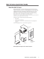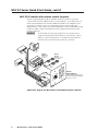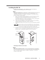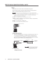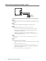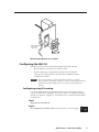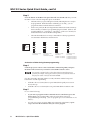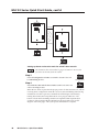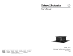
1
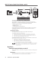
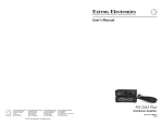
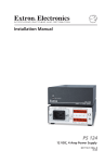
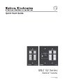
Quick Start Guide MLC 52 Series MediaLink™ Controller 68-1184-01 Rev. D 07 07 Precautions Safety Instructions • English Warning This symbol is intended to alert the user of important operating and maintenance (servicing) instructions in the literature provided with the equipment. Power sources • This equipment should be operated only from the power source indicated on the product. This equipment is intended to be used with a main power system with a grounded (neutral) conductor. The third (grounding) pin is a safety feature, do not attempt to bypass or disable it. This symbol is intended to alert the user of the presence of uninsulated dangerous voltage within the product's enclosure that may present a risk of electric shock. Power disconnection • To remove power from the equipment safely, remove all power cords from the rear of the equipment, or the desktop power module (if detachable), or from the power source receptacle (wall plug). Power cord protection • Power cords should be routed so that they are not likely to be stepped on or pinched by items placed upon or against them. Caution Read Instructions • Read and understand all safety and operating instructions before using the equipment. Retain Instructions • The safety instructions should be kept for future reference. Servicing • Refer all servicing to qualified service personnel. There are no user-serviceable parts inside. To prevent the risk of shock, do not attempt to service this equipment yourself because opening or removing covers may expose you to dangerous voltage or other hazards. Follow Warnings • Follow all warnings and instructions marked on the equipment or in the user information. Slots and openings • If the equipment has slots or holes in the enclosure, these are provided to prevent overheating of sensitive components inside. These openings must never be blocked by other objects. Avoid Attachments • Do not use tools or attachments that are not recommended by the equipment manufacturer because they may be hazardous. Lithium battery • There is a danger of explosion if battery is incorrectly replaced. Replace it only with the same or equivalent type recommended by the manufacturer. Dispose of used batteries according to the manufacturer's instructions. Consignes de Sécurité • Français Avertissement Ce symbole sert à avertir l’utilisateur que la documentation fournie avec le matériel contient des instructions importantes concernant l’exploitation et la maintenance (réparation). Alimentations• Ne faire fonctionner ce matériel qu’avec la source d’alimentation indiquée sur l’appareil. Ce matériel doit être utilisé avec une alimentation principale comportant un fil de terre (neutre). Le troisième contact (de mise à la terre) constitue un dispositif de sécurité : n’essayez pas de la contourner ni de la désactiver. Ce symbole sert à avertir l’utilisateur de la présence dans le boîtier de l’appareil de tensions dangereuses non isolées posant des risques d’électrocution. Déconnexion de l’alimentation• Pour mettre le matériel hors tension sans danger, déconnectez tous les cordons d’alimentation de l’arrière de l’appareil ou du module d’alimentation de bureau (s’il est amovible) ou encore de la prise secteur. Attention Lire les instructions• Prendre connaissance de toutes les consignes de sécurité et d’exploitation avant d’utiliser le matériel. Conserver les instructions• Ranger les consignes de sécurité afin de pouvoir les consulter à l’avenir. Respecter les avertissements • Observer tous les avertissements et consignes marqués sur le matériel ou présentés dans la documentation utilisateur. Eviter les pièces de fixation • Ne pas utiliser de pièces de fixation ni d’outils non recommandés par le fabricant du matériel car cela risquerait de poser certains dangers. Sicherheitsanleitungen • Deutsch Dieses Symbol soll dem Benutzer in der im Lieferumfang enthaltenen Dokumentation besonders wichtige Hinweise zur Bedienung und Wartung (Instandhaltung) geben. Dieses Symbol soll den Benutzer darauf aufmerksam machen, daß im Inneren des Gehäuses dieses Produktes gefährliche Spannungen, die nicht isoliert sind und die einen elektrischen Schock verursachen können, herrschen. Achtung Lesen der Anleitungen • Bevor Sie das Gerät zum ersten Mal verwenden, sollten Sie alle Sicherheitsund Bedienungsanleitungen genau durchlesen und verstehen. Aufbewahren der Anleitungen • Die Hinweise zur elektrischen Sicherheit des Produktes sollten Sie aufbewahren, damit Sie im Bedarfsfall darauf zurückgreifen können. Befolgen der Warnhinweise • Befolgen Sie alle Warnhinweise und Anleitungen auf dem Gerät oder in der Benutzerdokumentation. Keine Zusatzgeräte • Verwenden Sie keine Werkzeuge oder Zusatzgeräte, die nicht ausdrücklich vom Hersteller empfohlen wurden, da diese eine Gefahrenquelle darstellen können. Instrucciones de seguridad • Español Protection du cordon d’alimentation • Acheminer les cordons d’alimentation de manière à ce que personne ne risque de marcher dessus et à ce qu’ils ne soient pas écrasés ou pincés par des objets. Réparation-maintenance • Faire exécuter toutes les interventions de réparation-maintenance par un technicien qualifié. Aucun des éléments internes ne peut être réparé par l’utilisateur. Afin d’éviter tout danger d’électrocution, l’utilisateur ne doit pas essayer de procéder lui-même à ces opérations car l’ouverture ou le retrait des couvercles risquent de l’exposer à de hautes tensions et autres dangers. Fentes et orifices • Si le boîtier de l’appareil comporte des fentes ou des orifices, ceux-ci servent à empêcher les composants internes sensibles de surchauffer. Ces ouvertures ne doivent jamais être bloquées par des objets. Lithium Batterie • Il a danger d'explosion s'll y a remplacment incorrect de la batterie. Remplacer uniquement avec une batterie du meme type ou d'un ype equivalent recommande par le constructeur. Mettre au reut les batteries usagees conformement aux instructions du fabricant. Vorsicht Stromquellen • Dieses Gerät sollte nur über die auf dem Produkt angegebene Stromquelle betrieben werden. Dieses Gerät wurde für eine Verwendung mit einer Hauptstromleitung mit einem geerdeten (neutralen) Leiter konzipiert. Der dritte Kontakt ist für einen Erdanschluß, und stellt eine Sicherheitsfunktion dar. Diese sollte nicht umgangen oder außer Betrieb gesetzt werden. Stromunterbrechung • Um das Gerät auf sichere Weise vom Netz zu trennen, sollten Sie alle Netzkabel aus der Rückseite des Gerätes, aus der externen Stomversorgung (falls dies möglich ist) oder aus der Wandsteckdose ziehen. Schutz des Netzkabels • Netzkabel sollten stets so verlegt werden, daß sie nicht im Weg liegen und niemand darauf treten kann oder Objekte darauf- oder unmittelbar dagegengestellt werden können. Wartung • Alle Wartungsmaßnahmen sollten nur von qualifiziertem Servicepersonal durchgeführt werden. Die internen Komponenten des Gerätes sind wartungsfrei. Zur Vermeidung eines elektrischen Schocks versuchen Sie in keinem Fall, dieses Gerät selbst öffnen, da beim Entfernen der Abdeckungen die Gefahr eines elektrischen Schlags und/oder andere Gefahren bestehen. Schlitze und Öffnungen • Wenn das Gerät Schlitze oder Löcher im Gehäuse aufweist, dienen diese zur Vermeidung einer Überhitzung der empfindlichen Teile im Inneren. Diese Öffnungen dürfen niemals von anderen Objekten blockiert werden. Litium-Batterie • Explosionsgefahr, falls die Batterie nicht richtig ersetzt wird. Ersetzen Sie verbrauchte Batterien nur durch den gleichen oder einen vergleichbaren Batterietyp, der auch vom Hersteller empfohlen wird. Entsorgen Sie verbrauchte Batterien bitte gemäß den Herstelleranweisungen. Advertencia Este símbolo se utiliza para advertir al usuario sobre instrucciones importantes de operación y mantenimiento (o cambio de partes) que se desean destacar en el contenido de la documentación suministrada con los equipos. Alimentación eléctrica • Este equipo debe conectarse únicamente a la fuente/tipo de alimentación eléctrica indicada en el mismo. La alimentación eléctrica de este equipo debe provenir de un sistema de distribución general con conductor neutro a tierra. La tercera pata (puesta a tierra) es una medida de seguridad, no puentearia ni eliminaria. Este símbolo se utiliza para advertir al usuario sobre la presencia de elementos con voltaje peligroso sin protección aislante, que puedan encontrarse dentro de la caja o alojamiento del producto, y que puedan representar riesgo de electrocución. Desconexión de alimentación eléctrica • Para desconectar con seguridad la acometida de alimentación eléctrica al equipo, desenchufar todos los cables de alimentación en el panel trasero del equipo, o desenchufar el módulo de alimentación (si fuera independiente), o desenchufar el cable del receptáculo de la pared. Precaucion Protección del cables de alimentación • Los cables de alimentación eléctrica se deben instalar en lugares donde no sean pisados ni apretados por objetos que se puedan apoyar sobre ellos. Leer las instrucciones • Leer y analizar todas las instrucciones de operación y seguridad, antes de usar el equipo. Reparaciones/mantenimiento • Solicitar siempre los servicios técnicos de personal calificado. En el interior no hay partes a las que el usuario deba acceder. Para evitar riesgo de electrocución, no intentar personalmente la reparación/mantenimiento de este equipo, ya que al abrir o extraer las tapas puede quedar expuesto a voltajes peligrosos u otros riesgos. Conservar las instrucciones • Conservar las instrucciones de seguridad para futura consulta. Obedecer las advertencias • Todas las advertencias e instrucciones marcadas en el equipo o en la documentación del usuario, deben ser obedecidas. Evitar el uso de accesorios • No usar herramientas o accesorios que no sean especificamente recomendados por el fabricante, ya que podrian implicar riesgos. Ranuras y aberturas • Si el equipo posee ranuras o orificios en su caja/alojamiento, es para evitar el sobrecalientamiento de componentes internos sensibles. Estas aberturas nunca se deben obstruir con otros objetos. Batería de litio • Existe riesgo de explosión si esta batería se coloca en la posición incorrecta. Cambiar esta batería únicamente con el mismo tipo (o su equivalente) recomendado por el fabricante. Desachar las baterías usadas siguiendo las instrucciones del fabricante. ᅝܼ乏ⶹ • Ё᭛ 䖭Ͼヺোᦤ⼎⫼᠋䆹䆒⫼᠋ݠЁ ᳝䞡㽕ⱘ᪡㓈ᡸ䇈ᯢDŽ 䖭Ͼヺো䄺ਞ⫼᠋䆹䆒ᴎݙ᳝ 䴆ⱘॅ䰽⬉य़ˈ᳝㾺⬉ॅ䰽 ɿ 䄺ਞ ⬉⑤• 嬦嫿⡈⌫倾Ề䑩ᷨ␂ᵋ㝈㕏䗅䑶㷑ɿ嫿⡈⼆枼 Ề䑩㙊♱一䗅Ờ䑶䰼丠Ờ䑶ɿ 䩭ᵊ㚢一澠♱一澡㕰 ⫊₩嫿㓾澤ᵎ倾ᵎ䑩ㅗ崴弈ɿ ᢨᥝ⬉⑤• ᵻ⫊₩♱ḏ嫿⡈㈕㋊䑶㷑澤嬸㈕㋊ㆁ㙊嫿 ⡈⍏ㅗ㞍暣䑶㷑䗅䑶㷑一澤 ㅗḼẖ㋦ⅱⵃ䑶䰼丠䗅 䑶㷑一ɿ ⊼ᛣ ⬉⑤㒓ֱᡸ• ⣦Ⓟⵄ一澤忀₎埬嵪嵐澤ㅗ愎䆪㉥⋌ɿ 䯙䇏䇈ᯢк• 䑩ㅸỀ䑩嬦嫿⡈⼆枼敆嬼䍇夤ㆁ㙊⫊₩⏍Ề䑩嬵㕏ɿ 㓈ᡸ• ㆁ㙊丵Ἧ⼆枼䑲嫥嬂䗅丵Ἧ᷻⎙弜垍ɿ嫿⡈ 怩㯢㙊䑩ㅸ⌰Ḧ㘵㊣䗅昷ḷɿ ֱᄬ䇈ᯢк• 䑩ㅸⷕ⪙⫊₩嬵㕏ᶧḦ⡈⭇㚦Ề䑩ɿ 䙉ᅜ䄺ਞ • 䑩ㅸⷕ徶⫉ᷨ␂⏍䑩ㅸ㉈⊘ᵋ䗅ㆁ㙊⫊₩ ⏍㐎ẝ嬵㕏ɿ 䙓ܡ䗑ࡴ • ᵎ壂Ề䑩嬦ᷨ␂⋃⒇㯢㙊㋩劑䗅₸ㅗ弾 ⇡嫿⡈澤Ḧ忀₎⊲斪 ɿ ᵻ忀₎℻䋱大䑶⊲斪 ᵎ壂儫ⴲ嬖☿㆔⹁嫿⡈䘗⪑丵Ἧ嬦嫿⡈ɿ 䗮亢ᄨ• 㙊ᷜ嫿⡈㙻⠴ᵋ㙊彛栏㤾ㅗ⪕澤⫄ḭ㕰䑩㚦 敳㪣㙻㒐だ₄ḷ弈䀮ɿ ᵎ壂䑩Ḽẖᵝ壀㉢Ẑ彛 栏⪕ɿ 䫖⬉∴• ᵎ㪤䞯䗅㘵㊣䑶㮡ṛ㙊䅇㿹䗅⊲斪ɿ⼆枼Ề䑩 ᵏ⋃⫷㋩劑䗅䘹⍍ㅗ䘹弒⛌⌸䗅䑶㮡ɿ ㉊䂨䑠ᷨ⋃ 䗅⸻嫯⡅䍇ⷠ⹄䑶㮡ɿ MLC 52 Series Quick Start Guide About the MLC 52 Series The Extron MediaLink™ Controller 52 (MLC 52) provides infrared (IR) and/or RS-232 remote control of a projector or other display device. It is an economical, compact (one-gang size), easy-to-use controller designed for use with audiovisual equipment in sites such as an elementary or high school classroom, or a small conference room. The MLC 52 is available in four models: MLC 52 IR and MLC 52 IR VC, which control display devices by IR only, and MLC 52 RS and MLC 52 RS VC, which control displays by either IR or RS-232. The MLC 52 acts as a universal projector remote control panel to provide control of a projector’s power, input selection, and volume. The MLC 52 can be configured using three different methods: • IR Learning • IR data transfer (“beaming”) • Using projector control drivers with the Windows®-based configuration software The following diagram shows a typical MLC 52 application. IR or RS-232 Control DI SP Y LA F OF ON Projector w/ Internal Speakers PC L VO VID EO L VO ML 2 C5 Extron MLC 52 PC VGA w/ Audio Cable Basic MediaLink Controller DVD Composite Audio RCA MLC 52 application diagram with standard faceplate MLC 52 Series • Quick Start Guide 1 MLC 52 Series Quick Start Guide, cont’d MLC 52 VC models with volume control faceplate The two-gang sized MLC 52 IR VC and MLC 52 RS VC each have a projector volume control knob in addition to the six control buttons. To use this knob, you must connect the MLC 52 to an Extron MPA Series Mini Power Amplifier (sold separately), to which you can also connect the projector (see the application diagram below). The volume control knob adjusts the volume on the MPA, freeing up the two MLC volume control buttons to be reconfigured and used for other projector functions. C To use the MLC 52 in this type of application, the controller must be configured with the Windows-based MLC 52 control software. Refer to chapter 5, “Serial Communication,” in the MLC 52 User’s Manual, provided on the CD included with your MLC 52, for details. PC DVD VGA with Audio Extron MPA 122 S-video with Audio Extron SI 26X Mini Power Amplifier Ceiling Speakers (in parallel) 2 12 A MP UTS TP OU hms O 4/8 US U INP VCR TS C OTE REM R L Composite Video with Audio R L E V 10 L/MUT VO L WER PO R MPA Volume Control DI Switched Audio Output SP LA Y OF F ON PC RS-232 Projector Control ME LU VO VC R DV TO AU GE A IM D ML 2 C5 Extron MLC 52 RS VC Basic MediaLink Controller with IR or RS-232 hardwired projector control Projector Application diagram for MLC 52 RS VC with MPA 122 power amplifier 2 MLC 52 Series • Quick Start Guide Installing the MLC 52 The MLC can be installed into a wall or furniture. Follow the instructions appropriate to the mounting option you have selected. Step 1 Prepare the installation site as required for your MLC model (cut a hole in the wall or furniture, and install an electric wall box and/or mounting bracket). See “Mounting an electrical box” in chapter 2, “Installation,” of your MLC 52 User’s Manual, for details on this procedure. a. Refer to the appropriate template diagram in your user’s manual to find out the dimensions of the opening required for the size of the wall box or mounting bracket that you are using. If using both a wall box and mounting bracket, use the dimensions on the bracket template. b. Using a ruler, draw guidelines on the installation surface (wall or furniture) where the opening for the bracket or wall box will be cut. c. Feed cables through the wall box punch-out holes, and secure them with cable clamps. To prevent short circuits, the outer foil shield can be cut back to the point where the cable exits the cable clamp. Both braided and foil shields should be connected to an equipment ground at the other end of the cable. d. Insert the wall box into the opening, and attach it to the wall stud or furniture with nails or screws, leaving the front edge flush with the outer wall or furniture surface. The illustration applies to all sizes of wall boxes. Wall Stud Installation Cable Cable Clamp Screws or Nails Wall opening flush with edge of box Attaching a wall box to a wall stud Step 2 Make and/or install button labels as desired. By default, buttons are prelabeled for your convenience. However, you can replace these labels with included button labels. See “Replacing button labels” in chapter 2, “Installation,” of the user’s manual for the procedure. MLC 52 Series • Quick Start Guide 3 MLC 52 Series Quick Start Guide, cont’d Step 3 Attach cables to the control connector on the MLC 52 rear panel. The ports in this connector, from left to right, perform the following functions: F (Tx) — Transmits the RS-232 signal for projector control. This port is present on all models, but it is active only on the RS models. E (IR OUT) — Used for connecting an IR Emitter to issue IR commands. Up to two emitters can be wired to this port. There is a maximum of 100' wiring distance from the port to the emitter. D (GND) — Ground for IR and/or RS-232 projector control C (IR IN) — Used for connecting an optional IR Link or IRL 20, so that the IR 452 remote can control the MLC. B (GND) — Ground for the +12 VDC power A (+12V) — Power input for the product (12 VDC) RS-232 Tx (RS Models Only) IR out IR in 12V DC in F E D C B A Control connector pinout a. Wire the control IR port, if you are going to control the projector via IR. You can connect Extron IR Emitters or an IR Broadcaster to the IR Out port to control the display and/or input devices via infrared commands from the MLC. Up to two IR Emitters can be connected via this connector at one time. Wire the connector as shown in the following illustration. White striped wire only E D Modulated IR Ground IR Emitter Connect up to 2 IR Emitters max. (#70-283-01). 100 feet (30.5 m) maximum MLC 52 control connector F E D C B A IR For the IR Emitter only Wiring for IR control 4 MLC 52 Series • Quick Start Guide Place the head of each IR Emitter over or directly adjacent to the controlled device’s IR receiver. b. Wire the RS-232 (Tx) port (RS models only). If you have an RS model and want to control the projector via RS-232, connect a cable between the projector and this 3.5 mm, 6-pole direct insertion captive screw connector. Use the following illustration as a guide. Refer to “Wiring for RS-232 control” in chapter 2, “Installation,” of your MLC 52 User’s Manual, for details on cable pin assignments and the wiring procedure. F Transmit (Tx) D Ground ( ) To the display/projector's RS-232 port FEDCBA RS-232 Wiring for RS-232 control (RS models only) Projector/display device pinouts for RS-232 control vary. Refer to your projector/display device’s user manual for its RS-232 pin configuration. c. Wire the power connector. Connect the supplied external 12 VDC power supply to the power port as shown in the following diagram. B Ground ( ) A +12 VDC input An external power supply (12 VDC, 1A max.) MLC IR control port F E D C B A Ground all devices Connecting the MLC 52 to the external power supply Check the power supply’s polarity before connecting it to the MLC. d. (Optional) Wire the IR Link or IRL 20 to the IR In port, to provide IR control after the MLC is mounted. Refer to “Wiring for IR remote control” or “Wiring the IRL 20” in chapter 2, “Installation,” of the MLC 52 User’s Manual for the complete procedure. e. (Optional) If you have an MLC 52 IR VC or an MLC 52 RS VC, wire its volume control potentiometer to the MPA power amplifier. Refer to “Wiring the MLC 52 VC with an MPA power amplifier,” in chapter 2, “Installation,” of the MLC 52 User’s Manual, for the procedure. The MPA 122 or 181T mini power amplifiers are sold separately. MLC 52 Series • Quick Start Guide 5 MLC 52 Series Quick Start Guide, cont’d VOL/ MUTE 10V VOL 10V MLC 52 VC potentiometer Rear Panel 1 2 10V VOL 3 MPA 122 or MPA 181T Remote Port Wiring the VC potentiometer to the MPA remote volume control port Step 4 Attach cables to the projector and, optionally, the IR Link, the IR Emitter, and/or the IRL 20. Step 5 Connect power cords and turn on all the devices, including the MLC. Step 6 Configure the controller by using one of the following methods: • IR Learning (See “Configuring using IR Learning,” later in this guide.) • IR Data Transfer (“beaming”) (See “Configuring using IR data transfer (“beaming”),” later in this guide.) • Windows®-based configuration software (Refer to chapter 5, “Serial Communication,” in the MLC 52 User’s Manual, for detailed procedures for using the configuration software.) Step 7 Test the system. Press the MLC’s buttons, watch the display, and listen to the audio output. Step 8 Mount the MLC to the wall or furniture. 6 a. Disconnect the MLC’s power supply at the power source end (not at the MLC end). b. Disconnect the other devices’ power. c. Secure the faceplate onto the electrical wall box, mounting bracket, wall, or furniture. (Refer to “Mounting the MLC 52,” in chapter 2, “Installation,” of the MLC 52 User’s Manual.) d. Restore power to the MLC and all connected devices. MLC 52 Series • Quick Start Guide AY PL DIS F OF ON PC Wall opening is flush with edge of box. L VO EO VID L VO 2 C5 ML MLC 52 Mounting the MLC 52 in a wall box Configuring the MLC 52 The MLC 52 series can be programmed using the following methods: • IR Learning from your projector’s remote control • IR data transfer from another MLC 52 that has been configured • Using projector/display drivers with the MLC 52 Windows-based configuration software You can use IR drivers, via the configuration software, to configure either of the IR or RS models. However, in order to configure the RS models with RS-232 projector/display drivers, you must use the configuration software. Configuring using IR Learning You can use IR Learning to program the functions on your projector’s remote control into the buttons on the MLC front panel. Refer to “Configuring using IR learning” in chapter 3, “Operation,” of the MLC 52 User’s Manual for more details on this process. Step 1 Apply power to the MLC 52. Step 2 ON Set configuration switch #1 to On, on the rear panel, as shown at right. 1 2 3 4 MLC 52 Series • Quick Start Guide 7 MLC 52 Series Quick Start Guide, cont’d Step 3 Press the button on the MLC front panel that will store the IR code that you want the MLC to learn. The following takes place on the MLC: • The button that you pressed begins to blink, indicating that it is ready to be programmed. While the button is blinking (5 seconds), you can program the button with the desired command. • On the rear panel, the IR Learning LED that indicates the button memory block currently available for programming begins to blink. (Refer to “IR Learning indicators,” in chapter 3, “Operation,” of the user’s manual, for further information about the IR Learning LEDs.) • The LED that indicates how many commands have been programmed onto the button illuminates and remains lit. E E E E LED Off 4 4 4 4 LED Blinking 3 3 3 3 2 2 2 2 1 1 1 LED On 1 Command 1 is ready to be learned. Command 2 is ready to be learned. Command 1 was learned. Command 3 is ready to be learned. Command 2 was learned. Command 1 was learned. Command 4 is ready to be learned. Command 3 was learned. Command 2 was learned. Command 1 was learned. Activation of LEDs during button programming Step 4 Point the projector’s remote control at the MLC’s IR Learning LEDs, and press the button whose function you want the selected MLC button to learn. For repeating command codes, such as those that increment/decrement a function (for example, turning the volume up and down), hold the button on the projector remote control for at least 3 seconds. If no IR command is detected within 5 seconds, the LEDs and the front panel button time out and stop blinking. • If the IR code was learned, the rear panel LEDs blink rapidly in succession down, then up. • If the IR code was not learned, the rear panel LEDs blink in random order. Step 5 Do one of the following: 8 • If you want to program another command onto the same button, press the button again. The Learning LED on the rear panel that is next to be programmed begins flashing. (You can program up to four commands on one button.) • If you do not want to program additional commands on the button, repeat steps 3 and 4 for the next button that you want to program. MLC 52 Series • Quick Start Guide Step 6 When finished programming buttons, set configuration switch #1 on the rear panel to Off. Verify that the commands you entered have been learned by pressing the buttons that you programmed. Removing commands from a button If you want to delete one or more commands that have been programmed onto a button, you must remove all the commands programmed to that button. Follow these steps: 1. While the MLC 52 is powered on, make sure that configuration DIP switch #1 is set to On. 2. Press the button for which you want to delete commands, and within 2 seconds press the same button again. The IR Learning LEDs on the rear panel turn off. 3. Verify that the button’s commands were erased by pressing the same button again. If the commands have been erased, only LED #1 (the bottom LED) should be blinking; the other LEDs should be off. 4. Repeat steps 2 and 3 for any additional buttons, or place configuration DIP switch #1 in the Off position. Configuring using IR data transfer (“beaming”) You can configure your MLC 52 by transferring button configuration data to it from another configured MLC 52. Data transfer is done via the IR Transmit and Receive LEDs on the back panels of the MLCs. With this method, you replicate the other MLC’s configuration on your own unit without the use of software or cables. The following transfers are allowed: • From an RS model to another RS model • From an IR model to another IR model • From an IR model to an RS model N You cannot transmit data from an RS model to an IR model. Step 1 Make sure that power is connected and applied to both units, and that all switches on the rear panels of both units are set to the Off position. Step 2 Position the two units so that the IR Transmit and Receive LEDs of both MLCs are facing each other, and no more than 6 inches apart. (See the diagram on the next page.) MLC 52 Series • Quick Start Guide 9 MLC 52 Series Quick Start Guide, cont’d Tx IR OUT 1 GND IR IN GND + 12V Less Than 6” 1 2 3 4 2 3 ON 4 E E 4 3 IR Beaming ON 2 + 12V GND IR IN 1 2 3 4 GND IR OUT Tx 1 ON 1 2 3 4 Transmitting MLC ON 1 2 3 4 Receiving MLC Setting up donor and receiver units for wireless data transfer The illustrations show the standard (1-gang sized) MLC 52. However, the procedures are the same for the VC models. Step 3 Leave all configuration switches set to Off on the MLC that will be transmitting the data. Step 4 Set switch #2 to On and all other switches to Off on the MLC that will be receiving the data. ON 1 2 3 4 Transmitting MLC ON 1 2 3 4 Receiving MLC When the two units are placed in the proper position for data transmission, and the receiving unit’s configuration switch #2 is set to On, the transmitting and receiving units detect each other’s presence, and the data transfer begins automatically. During data transfer, the front panel buttons act as progress indicators. The buttons on both the transmitting and the receiving MLCs blink sequentially in clockwise order, starting with the ON button in the upper-left corner (see the diagram on the next page). This cycle repeats until transfer is complete. 10 MLC 52 Series • Quick Start Guide DISPLAY ON VOL VOL OFF PC VIDEO MLC 52 Order in which the buttons blink during data transfer After each 17% of the data has been transferred, the next button in the order of lights remains lit brightly. This continues until the transfer process is complete and all buttons are permanently lit. By observing how many buttons are lit steadily, you can see approximately how much data has been transferred. The buttons on the MLC VC models blink in the same pattern as the standard models. Step 5 When data transfer is complete, do either of the following: • If you are finished transferring data, return configuration switch #2 on the receiving MLC to the Off position. Reinitialize the receiving unit by pressing any of its front panel buttons. • If you want to repeat the transfer process to configure another MLC 52, repeat steps 2 and 3 for the unit that will be configured. Press any button on the donor unit. The transfer process restarts. Configuring using RS-232 The MLC 52 front panel contains a configuration port that can be used for configuring the MLC with the Windows-based configuration software that is included on the CD provided with your MLC. With this software, you can use projector/display drivers to configure the MLC 52 and to access advanced configuration options. Both the IR and the RS models can be configured via the RS-232 configuration port on the front panel, using the Windows-based configuration software. In order for the RS models to control a projector/display device using RS-232 drivers, you must configure the MLC using the configuration software. You can also use IR drivers to configure the IR or RS models via the configuration software. Use a 2.5 mm TRS to 9-pin D-sub connector cable to connect the MLC to your computer via this 2.5 mm female connector. (This cable is an optional accessory that can be ordered from Extron (part #70-335-01). The protocol for this connector is 9600 bits per second, 8 data bits, 1 stop bit, no parity. MLC 52 Series • Quick Start Guide 11 MLC 52 Series Quick Start Guide, cont’d To Front Panel Config Port MLC 52 6 feet (1.8 m) DISPLAY ON 1 5 OFF Part #70-335-01 6 9 PC VOL Tip Ring Sleeve (Gnd) Computer 9-pin D Connection TRS Plug Pin 2 Pin 3 Pin 5 Computer's RX line Computer's TX line Computer's signal ground Tip Ring Sleeve VOL VIDEO MLC 52 2.5 mm Configuration Port 2.5 mm connector cable for the configuration port The included CD contains the configuration software and various projector/ display drivers. To install and run the MLC 52 Configuration program software, ensure that your PC meets the following minimum requirements: • Windows 2000, XP, or higher • 400 MHz processor • 32 MB (megabytes) free hard disk space Extron’s Windows-based configuration software is provided on a CD included with the MLC, and updates can be downloaded from the Extron Web site (www.extron.com). Installing the software The configuration program requires about 32 MB of hard disk space. To install the software onto the hard drive: 1. Insert the CD ROM into your CD drive. The disk starts automatically. 2. If the disk does not start automatically, run LAUNCH.EXE from the CD. 3. Follow the instructions that appear on the screen. By default the installation creates a directory called “MediaLink” on the PC hard drive, and places the following two icons in it: • MediaLnk52.exe (MediaLink Configuration program) • MLC 52Wizard.exe (MediaLink Configuration Wizard) • MLC 52 DVCM50 Help.chm (MLC 52 and DVCM 50 Help) Refer to chapter 5, “Serial Communication,” of the MLC 52 User’s Manual, also included on the CD, for detailed instructions on configuring the MLC using this software. Operations Powering the projector/display on and off The On and Off buttons on the MLC 52 front panel are used to power the projector on and off. Powering on Press and release the Projector On button to turn the display device’s power on. The On button blinks for 4 seconds, then remains steadily lit. 12 MLC 52 Series • Quick Start Guide Powering off To turn the projector/display off, press the Off button. The button blinks for 4 seconds, then remains steadily lit. The power On and Off buttons blink while the projector is warming up and cooling down. The warm-up and cool-down delay periods can be changed via the Windows-based configuration software. Locking the Front Panel (Executive Mode) When the MLC 52 is in executive mode, all front panel functions are locked, so that pressing them has no effect. If a button is pressed while the MLC is in executive mode, all the front panel buttons blink, indicating that the front panel is locked out. Follow these steps to enable executive mode: Step 1 Power off the projector or plasma display. Executive mode cannot be enabled if the display device is on. Step 2 • On the standard models, press and hold the Vol > and Video buttons simultaneously for 5 seconds. • On the VC models, press and hold the unlabeled button (bottom right) and the VCR button simultaneously for 5 seconds. When the MLC enters executive mode, all front panel buttons blink three times, then return to their original state. DISPLAY ON VOL VOL DISPLAY ON OFF PC VCR PC VIDEO DVD OFF VOLUME MLC 52 MLC 52 Buttons to press for executive mode To exit executive mode, press the same two buttons again, holding them for 5 seconds. MLC 52 Series • Quick Start Guide 13 www.extron.com Extron Electronics, USA 1230 South Lewis Street Anaheim, CA 92805 800.633.9876 714.491.1500 FAX 714.491.1517 Extron Electronics, Europe Beeldschermweg 6C 3821 AH Amersfoort, The Netherlands +800.3987.6673 +31.33.453.4040 FAX +31.33.453.4050 Extron Electronics, Asia 135 Joo Seng Rd. #04-01 PM Industrial Bldg., Singapore 368363 +800.7339.8766 +65.6383.4400 FAX +65.6383.4664 © 2007 Extron Electronics. All rights reserved. Extron Electronics, Japan Kyodo Building, 16 Ichibancho Chiyoda-ku, Tokyo 102-0082 Japan +81.3.3511.7655 FAX +81.3.3511.7656