1
LG plus Series
Text and Graphics Printers
TM
Maintenance Manual
Order Number: EK–LGPLE–MM.A01
Digital Equipment Corporation
FCC Notice
This equipment has been tested and found to comply with the limits of a Class A digital device, pursuant to Part 15 of the FCC
Rules. These limits are designed to provide a reasonable protection against harmful interference when the equipment is
operated in a commercial environment. This equipment generates, uses, and can radiate radio frequency energy and, if not
installed and used in accordance with the instruction manual, may cause harmful interference to radio communications.
Operation of this equipment in a residential area is likely to cause harmful interference, in which case the user will be required
to correct the interference at his own expense. Any changes or modifications not expressly approved by the manufacturer
could void the user’s authority to operate the equipment.
Installing this equipment in an FCC Level B composite system results in an FCC Level A Composite System as defined in the
FCC Rules and Regulations.
Canadian Department of Communications compliance statement:
This equipment does not exceed Class A limits per radio noise emissions for digital apparatus as set out in the Radio
Interference Regulation of the Canadian Department of Communications. Operation in a residential area may cause
unacceptable interference to radio and TV reception requiring the owner or operator to take whatever steps are necessary to
correct the interference.
Avis de conformite aux normes du ministere des Communications du Canada:
Cet equipment ne depasse pas les limites de Classe A d’emission de bruits radioelectriques pour les appareils numerriques
tells que perscrites par le Reglement sur le brouillage radioelectriques etabli par le ministere des Communications du Canada.
L’exploitation faite en milieu residentiel peut entrainer le brouillage des receptions radio et tele, ce qui obligerait le proprietaire
ou l’operateur a prendre les dispositions necessarires pour en eliminer les cause.
The following statements are required in accordance with CISPR–22.
This is a Class A product. In a domestic environment this product may cause radio interference in which case the user may be
required to take adequate measures.
Dieses ist ein Gern der Funkstrgrenzwertklasse A. In Wohnbereichen knnen bei Betreib dieses Gertes Rundfunkstrungen
auftreten, in welchen Fllen der Benutzer frentsprechende Gegenmahmen verantwortlich ist.
Ceci est un produit de Classe A. Dans un environment domestique, ce produit risque de crer des interfrences radiolectriques, il
appartiesdra alors l’utilisateur de prendre les mesures specifiques appropries.
All Rights Reserved. December 1995.
The information in this document is subject to change without notice and should not be construed as a commitment by Digital
Equipment Corporation. Digital Equipment Corporation assumes no responsibility for any errors that may appear in this
document.
Digital Equipment Corporation makes no representations that the use of its products in the manner described in this publication
will not infringe on existing or future patent rights, nor do the descriptions contained in this publication imply the granting of
licenses to make, use, or sell equipment or software in accordance with the description.
Possession, use, or copying of the software described in this publication is authorized only pursuant to a valid written license
from Digital or an authorized sublicensor.
Digital Equipment Corporation 1995. Printed in U.S.A.
The following are trademarks of Digital Equipment Corporation: DEClaser, DECnet, DECserver, OpenVMS, PrintServer,
ThinWire, ULTRIX, VAX, and the DIGITAL logo.
PostScriptTM is a trademark of Adobe Systems Incorporated, which may be registered in certain jurisdictions. AppleTalk,
LocalTalk, LaserWriter, and Macintosh are registered trademarks of Apple Computer, Inc. Microsoft, MS, MS–DOS, and
Windows NT are registered trademarks of Microsoft Corporation. Centronics is a trademark of Centronics Data Computer
Corporation. IBM is a registered trademark and IBM PC/AT is a trademark of International Business Machines Corporation.
All other trademarks and registered trademarks are the property of their respective holders.
Table of Contents
1
Maintenance Overview
About the Printer . . . . . . . . . . . . . . . . . . . . . . . . . . . . . . . . . . . . . . . . . . . . . . . 1–2
Important Maintenance Notes . . . . . . . . . . . . . . . . . . . . . . . . . . . . . . . . . 1–2
About This Manual . . . . . . . . . . . . . . . . . . . . . . . . . . . . . . . . . . . . . . . . . . . . . 1–3
How to Use This Manual . . . . . . . . . . . . . . . . . . . . . . . . . . . . . . . . . . . . . 1–3
Notes and Notices . . . . . . . . . . . . . . . . . . . . . . . . . . . . . . . . . . . . . . . . . . . 1–3
Related Documents . . . . . . . . . . . . . . . . . . . . . . . . . . . . . . . . . . . . . . . . . 1–4
Printing Conventions in This Manual . . . . . . . . . . . . . . . . . . . . . . . . . . . 1–5
Safety Notices . . . . . . . . . . . . . . . . . . . . . . . . . . . . . . . . . . . . . . . . . . . . . . . . . 1–6
Controls and Indicators . . . . . . . . . . . . . . . . . . . . . . . . . . . . . . . . . . . . . . . . . . 1–8
Electrical Controls and Indicators, Cabinet Models . . . . . . . . . . . . . . . . 1–8
Mechanical Controls and Indicators . . . . . . . . . . . . . . . . . . . . . . . . . . . . . 1–10
Tools, Test Equipment, and Supplies . . . . . . . . . . . . . . . . . . . . . . . . . . . . . . . 1–12
2
Scheduled Maintenance
Preventive Maintenance Checks and Services . . . . . . . . . . . . . . . . . . . . . . . . 2–2
Inspecting the Printer . . . . . . . . . . . . . . . . . . . . . . . . . . . . . . . . . . . . . . . . . . . 2–3
Cleaning the Printer . . . . . . . . . . . . . . . . . . . . . . . . . . . . . . . . . . . . . . . . . . . . 2–4
Cleaning the Cabinet and Print Mechanism . . . . . . . . . . . . . . . . . . . . . . . 2–4
Cleaning the Shuttle Frame Assembly . . . . . . . . . . . . . . . . . . . . . . . . . . . 2–6
Cleaning the Card Cage Fan Assembly . . . . . . . . . . . . . . . . . . . . . . . . . . 2–8
3
Troubleshooting
Introduction . . . . . . . . . . . . . . . . . . . . . . . . . . . . . . . . . . . . . . . . . . . . . . . . . . . 3–2
Troubleshooting Aids . . . . . . . . . . . . . . . . . . . . . . . . . . . . . . . . . . . . . . . . . . . 3–2
Fault Messages . . . . . . . . . . . . . . . . . . . . . . . . . . . . . . . . . . . . . . . . . . . . . . . . 3–3
Symptoms Not Indicated by Fault Messages . . . . . . . . . . . . . . . . . . . . . . . . . 3–29
Troubleshooting Table . . . . . . . . . . . . . . . . . . . . . . . . . . . . . . . . . . . . . . . 3–30
i
Printer Confidence Check . . . . . . . . . . . . . . . . . . . . . . . . . . . . . . . . . . . . . . . . 3–34
Diagnostic Printer Tests . . . . . . . . . . . . . . . . . . . . . . . . . . . . . . . . . . . . . . . . . 3–35
Selecting and Running Diagnostic Printer Tests . . . . . . . . . . . . . . . . . . . 3–37
Hidden Diagnostic Menu . . . . . . . . . . . . . . . . . . . . . . . . . . . . . . . . . . . . . 3–39
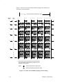
Hex Code Printout . . . . . . . . . . . . . . . . . . . . . . . . . . . . . . . . . . . . . . . . . . . . . 3–41
ASCII Character Set . . . . . . . . . . . . . . . . . . . . . . . . . . . . . . . . . . . . . . . . . 3–43
4
Adjustment Procedures
Preparing the Printer for Maintenance . . . . . . . . . . . . . . . . . . . . . . . . . . . . . . 4–2
Returning the Printer to Normal Operation . . . . . . . . . . . . . . . . . . . . . . . . . . 4–3
Belt, Paper Feed Timing, Adjustment . . . . . . . . . . . . . . . . . . . . . . . . . . . . . . 4–4
Belt, Platen Open, Adjustment . . . . . . . . . . . . . . . . . . . . . . . . . . . . . . . . . . . . 4–6
Paper Drive Motor Pulley Alignment . . . . . . . . . . . . . . . . . . . . . . . . . . . . . . . 4–8
Paper Scale Alignment . . . . . . . . . . . . . . . . . . . . . . . . . . . . . . . . . . . . . . . . . . 4–10
Platen Gap Adjustment . . . . . . . . . . . . . . . . . . . . . . . . . . . . . . . . . . . . . . . . . . 4–12
Platen Open Motor Pulley Alignment . . . . . . . . . . . . . . . . . . . . . . . . . . . . . . 4–14
Ribbon Guide Alignment . . . . . . . . . . . . . . . . . . . . . . . . . . . . . . . . . . . . . . . . 4–16
Splined Shaft Skew Adjustment . . . . . . . . . . . . . . . . . . . . . . . . . . . . . . . . . . . 4–18
Adjusting the End of Forms Distance . . . . . . . . . . . . . . . . . . . . . . . . . . . . . . . 4–20
Hammer Phasing Adjustment . . . . . . . . . . . . . . . . . . . . . . . . . . . . . . . . . . . . . 4–25
Installing Software . . . . . . . . . . . . . . . . . . . . . . . . . . . . . . . . . . . . . . . . . . . . . 4–27
5
Replacement Procedures and Illustrated Parts List
Organization of This Chapter . . . . . . . . . . . . . . . . . . . . . . . . . . . . . . . . . . . . . 5–4
Section I: Replacement Procedures
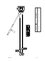
Belt, Paper Feed Timing . . . . . . . . . . . . . . . . . . . . . . . . . . . . . . . . . . . . . . . . . 5–5
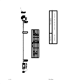
Belt, Platen Open . . . . . . . . . . . . . . . . . . . . . . . . . . . . . . . . . . . . . . . . . . . . . . 5–7
Cable Connectors and Connector Shells . . . . . . . . . . . . . . . . . . . . . . . . . . . . . 5–8
Circuit Board: Controller . . . . . . . . . . . . . . . . . . . . . . . . . . . . . . . . . . . . . . . . 5–10
Circuit Board: Power Supply . . . . . . . . . . . . . . . . . . . . . . . . . . . . . . . . . . . . . 5–12
Circuit Breaker . . . . . . . . . . . . . . . . . . . . . . . . . . . . . . . . . . . . . . . . . . . . . . . . 5–13
ii
Control Panel Assembly . . . . . . . . . . . . . . . . . . . . . . . . . . . . . . . . . . . . . . . . . 5–14
Cover Assembly, Hammer Bank / Ribbon Mask . . . . . . . . . . . . . . . . . . . . . . 5–15
Cover Assembly, Shuttle . . . . . . . . . . . . . . . . . . . . . . . . . . . . . . . . . . . . . . . . . 5–16
Fan Assembly, Card Cage . . . . . . . . . . . . . . . . . . . . . . . . . . . . . . . . . . . . . . . . 5–17
Fan Assembly, Cabinet Exhaust . . . . . . . . . . . . . . . . . . . . . . . . . . . . . . . . . . . 5–18
Fan Assembly, Hammer Bank . . . . . . . . . . . . . . . . . . . . . . . . . . . . . . . . . . . . 5–19
Magnetic Pick–up (MPU) Assembly . . . . . . . . . . . . . . . . . . . . . . . . . . . . . . . 5–20
Memory Modules and Security PAL . . . . . . . . . . . . . . . . . . . . . . . . . . . . . . . 5–21
Motor Assembly, Paper Feed . . . . . . . . . . . . . . . . . . . . . . . . . . . . . . . . . . . . . 5–23
Motor Assembly, Platen Open . . . . . . . . . . . . . . . . . . . . . . . . . . . . . . . . . . . . 5–25
Motor Assembly, Ribbon Drive . . . . . . . . . . . . . . . . . . . . . . . . . . . . . . . . . . . 5–27
Paper Ironer . . . . . . . . . . . . . . . . . . . . . . . . . . . . . . . . . . . . . . . . . . . . . . . . . . 5–28
Paper Path . . . . . . . . . . . . . . . . . . . . . . . . . . . . . . . . . . . . . . . . . . . . . . . . . . . . 5–29
Platen . . . . . . . . . . . . . . . . . . . . . . . . . . . . . . . . . . . . . . . . . . . . . . . . . . . . . . . 5–30
Resistors, Terminating . . . . . . . . . . . . . . . . . . . . . . . . . . . . . . . . . . . . . . . . . . 5–35
Ribbon Hub . . . . . . . . . . . . . . . . . . . . . . . . . . . . . . . . . . . . . . . . . . . . . . . . . . . 5–38
Ribbon Guide Assembly (L/R) . . . . . . . . . . . . . . . . . . . . . . . . . . . . . . . . . . . . 5–37
Shaft, Splined . . . . . . . . . . . . . . . . . . . . . . . . . . . . . . . . . . . . . . . . . . . . . . . . . 5–39
Shaft, Support . . . . . . . . . . . . . . . . . . . . . . . . . . . . . . . . . . . . . . . . . . . . . . . . . 5–41
Shuttle Frame Assembly . . . . . . . . . . . . . . . . . . . . . . . . . . . . . . . . . . . . . . . . . 5–42
Spring Assembly, Gas . . . . . . . . . . . . . . . . . . . . . . . . . . . . . . . . . . . . . . . . . . . 5–44
Spring, Extension, Hammer Bank . . . . . . . . . . . . . . . . . . . . . . . . . . . . . . . . . 5–45
Switch Assembly, Paper Detector . . . . . . . . . . . . . . . . . . . . . . . . . . . . . . . . . . 5–46
Switch Assembly, Platen Interlock . . . . . . . . . . . . . . . . . . . . . . . . . . . . . . . . . 5–48
Tractor (L/R) . . . . . . . . . . . . . . . . . . . . . . . . . . . . . . . . . . . . . . . . . . . . . . . . . . 5–50
Section II: Illustrated Parts List
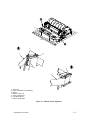
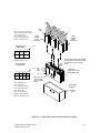
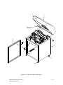
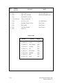
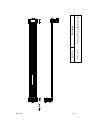
Figure 5–7. Top Cover, Doors, and Casters . . . . . . . . . . . . . . . . . . . . . . . . . . 5–53
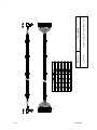
Figure 5–8. Paper Fence and Chains . . . . . . . . . . . . . . . . . . . . . . . . . . . . . . . 5–55
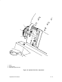
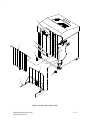
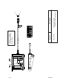
Figure 5–9. Operator Panel and Cabinet Details . . . . . . . . . . . . . . . . . . . . . . 5–57
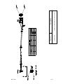
Figure 5–10. Covers . . . . . . . . . . . . . . . . . . . . . . . . . . . . . . . . . . . . . . . . . . . . 5–59
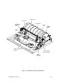
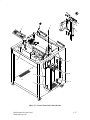
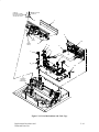
Figure 5–11. Print Mechanisms and Circuit Boards . . . . . . . . . . . . . . . . . . . . 5–61
Figure 5–12. Magnetic Pickup Unit (MPU) and Extension Spring . . . . . . . . 5–63
Figure 5–13. Tractor Shafts . . . . . . . . . . . . . . . . . . . . . . . . . . . . . . . . . . . . . . 5–65
iii
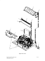
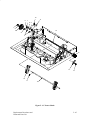
Figure 5–14. Platen . . . . . . . . . . . . . . . . . . . . . . . . . . . . . . . . . . . . . . . . . . . . . 5–67
Figure 5–15. Motors, Fans, and Paper Detector Switch . . . . . . . . . . . . . . . . . 5–69
Figure 5–16. Circuit Breaker . . . . . . . . . . . . . . . . . . . . . . . . . . . . . . . . . . . . . 5–71
6
Principles of Operation
Line Matrix Printing . . . . . . . . . . . . . . . . . . . . . . . . . . . . . . . . . . . . . . . . . . . . 6–2
Printing Mechanism . . . . . . . . . . . . . . . . . . . . . . . . . . . . . . . . . . . . . . . . . . . . 6–5
Shuttle Frame Assembly . . . . . . . . . . . . . . . . . . . . . . . . . . . . . . . . . . . . . 6–5
Paper Transport System . . . . . . . . . . . . . . . . . . . . . . . . . . . . . . . . . . . . . . 6–7
Ribbon Transport System . . . . . . . . . . . . . . . . . . . . . . . . . . . . . . . . . . . . . 6–8
Logical Control of the Printer . . . . . . . . . . . . . . . . . . . . . . . . . . . . . . . . . . . . . 6–9
Control Panel . . . . . . . . . . . . . . . . . . . . . . . . . . . . . . . . . . . . . . . . . . . . . . . . . 6–10
CMX Controller Board . . . . . . . . . . . . . . . . . . . . . . . . . . . . . . . . . . . . . . . . . . 6–11
Data Controller . . . . . . . . . . . . . . . . . . . . . . . . . . . . . . . . . . . . . . . . . . . . . 6–13
Engine Controller . . . . . . . . . . . . . . . . . . . . . . . . . . . . . . . . . . . . . . . . . . . 6–16
Power Supply Board . . . . . . . . . . . . . . . . . . . . . . . . . . . . . . . . . . . . . . . . . . . . 6–18
Printer Interface . . . . . . . . . . . . . . . . . . . . . . . . . . . . . . . . . . . . . . . . . . . . . . . 6–19
Graphics . . . . . . . . . . . . . . . . . . . . . . . . . . . . . . . . . . . . . . . . . . . . . . . . . . . . . 6–19
Appendixes
Index
iv
A
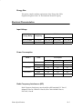
Wire Data
B
Printer Specifications
C
Metric Conversion Tables
D
Torque Table
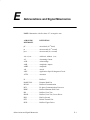
E
Abbreviations and Signal Mnemonics
F
Noise Suppression Devices
1
Maintenance Overview
Chapter Contents
About the Printer . . . . . . . . . . . . . . . . . . . . . . . . . . . . . . . . . . . . . . . . 1–2
Important Maintenance Notes . . . . . . . . . . . . . . . . . . . . . . . . . . . 1–2
About This Manual . . . . . . . . . . . . . . . . . . . . . . . . . . . . . . . . . . . . . . 1–3
How to Use This Manual . . . . . . . . . . . . . . . . . . . . . . . . . . . . . . 1–3
Notes and Notices . . . . . . . . . . . . . . . . . . . . . . . . . . . . . . . . . . . . 1–3
Related Documents . . . . . . . . . . . . . . . . . . . . . . . . . . . . . . . . . . . 1–4
Printing Conventions in This Manual . . . . . . . . . . . . . . . . . . . . . 1–5
Safety Notices . . . . . . . . . . . . . . . . . . . . . . . . . . . . . . . . . . . . . . . . . . 1–6
Controls and Indicators . . . . . . . . . . . . . . . . . . . . . . . . . . . . . . . . . . . 1–8
Electrical Controls and Indicators . . . . . . . . . . . . . . . . . . . . . . . . 1–8
Mechanical Controls and Indicators . . . . . . . . . . . . . . . . . . . . . . 1–10
Tools, Test Equipment, and Supplies . . . . . . . . . . . . . . . . . . . . . . . . . 1–12
Maintenance Overview
1–1
About the Printer
The LG plus Series is a family of line matrix printers: The LG04 plus prints at a
maximum rate of 475 lines per minute (lpm). The LG08 plus prints at a
maximum rate of 800 lpm, and the LG12 plus has a maximum print rate of
1200 lpm. Each model is housed in a quiet floor cabinet. These rugged and
reliable line printers represent the state of the art in line matrix printing
technology.
LG plus Series printers feature a flash memory architecture that permits rapid
access to stored printer emulations. All models use a variable–speed shuttle,
half–step paper feed control, and system architecture contained on a single
circuit board, enabling them to print high–volume jobs with minimum
maintenance, maximum reliability, and an impressive variety of print
options.
Although technologically advanced, LG plus Series printers are easy to use.
The user can select every printer function at the control panel or by sending
printer control codes in the data stream from the host computer.
Important Maintenance Notes
To maintain optimum printer performance, remember these important
maintenance concepts when you service the printer:
1–2
♦
Use only the ribbons specified in Appendix B. Use of incorrect ribbons
can lead to ink migration problems, degraded print quality, and expensive
damage to the printer.
♦
Incorrect closure of the forms thickness lever can lead to smearing,
degraded print quality, paper jams, and damage to the platen and shuttle
assembly. Never close the forms thickness lever too tightly.
♦
The hammer springs and hammer tips on the hammer bank are extremely
delicate and precisely aligned. Never bend or tweak hammer springs and
always handle hammer springs by the thick mounting base of the fret.
♦
Do not adjust the platen gap unless a new shuttle frame assembly or
platen was installed.
Maintenance Overview
About This Manual
This is a field service maintenance manual. It is designed so that you can
quickly locate maintenance information.
How to Use This Manual
1. Locate the procedure or information you need:
♦
Use the Table of Contents at the front of the manual.
♦
Use the Chapter Contents listed at the front each chapter.
♦
Use the Index at the back of the manual.
2. Read the entire procedure before you do it.
3. Gather the parts and tools you will need.
4. Read the Safety Notices on page 1–6. Make sure you understand all
safety notices before you start a task. (Notes and notices are defined
below.)
Notes and Notices
For your safety and to protect valuable equipment, read and comply with all
information highlighted under notes and notices. The heading of a notice tells
you the kind of information it contains:
WARNING
Conditions that could harm you as well as damage the equipment.
CAUTION
Conditions that could damage the printer or related equipment.
IMPORTANT
Vital information about proper operation of the printer.
NOTE: Tips for efficient operation and maintenance of the equipment.
Maintenance Overview
1–3
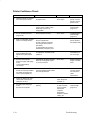
Related Documents
This manual does not explain how to operate or configure the printer. For
that information, refer to the following documents:
1–4
♦
LGplus Series Operator’s Guide
(Order Number EK–LGPLE–OG.A01)
♦
LGplus Series Setup Guide
(Order Number EK–LGPLS–SG.A01)
♦
LGplus Series Line Printer Plus Programmer’s Reference Manual
(Order Number EK–LGPLE–RM.A01)
♦
LGplus Series (LG) Programmer’s Reference Manual
(Order Number EK–LGPLP–RM.A01)
♦
LGplus Series PGL Programmer’s Manual
(Order Number EK–LGPGL–PM.A01)
♦
LGplus Series VGL Programmer’s Manual
(Order Number EK–LGVGL–PM.A01)
Maintenance Overview
Printing Conventions in This Manual
BOLD UPPERCASE print indicates control panel keys.
Example: Press the CLEAR key, then press the ON LINE key.
Quotation marks (“”) indicate messages you see on the Liquid Crystal
Display (LCD).
Example: Press the ON LINE key. “Off Line” appears on the LCD.
The + (plus) symbol represents key combinations.
Example: “Press Y + B ” means press the Y (UP) key and the B
(DOWN) key at the same time.
Some printer controls have no label on the printer. These controls are printed
lowercase. Example: “Set the forms thickness lever to the fully open
position.” (The control in this case is the forms thickness lever.)
Maintenance Overview
1–5
Safety Notices
WARNING
To prevent serious personal injury from electrical shock when
connecting or disconnecting the signal cable, set the printer power
switch to the off position and unplug the power cable.
WARNING
Always disconnect the AC power cord from the power source before
performing any maintenance procedure. Failure to remove power could
result in injury to persons or damage to equipment. If you must apply
power during maintenance, you will be instructed to do so in the
maintenance procedure.
WARNING
Always disconnect the AC power cord before cleaning the printer.
WARNING
To prevent injury from electric shock, wait at least one minute after
shutting off power before removing the power supply circuit board.
Wear a properly grounded static wrist strap when handling the power
supply board. Handle the board by the sides. Do not touch components
or flex the board during removal/installation.
WARNING
Over time, the upper edge of the paper ironer can become sharp. To
avoid cutting yourself, handle the paper ironer on the sides.
WARNING
Hold the printer cover securely while disengaging the gas spring
assembly.
WARNING
Use caution when configuring the printer. Exposed moving parts can
cause injury, and electrical currents are shock hazards.
1–6
Maintenance Overview
Hinweise zur Sicherheit
GERMAN
VORSICHT
Um ernstliche körperliche Verletzungen durch Stromschlag beim
Anschließen oder Trennen des Signalton-Kabels zu vermeiden, muß der
Drucker auf jeden Fall ausgeschaltet und der Netzstecker herausgezogen
werden.
VORSICHT
Bevor Sie anfällige Wartungsarbeiten durchführen, müssen Sie zuerst
immer das Netzkabel aus der Steckdose ziehen. Wird das Netzkabel
nicht herausgezogen, können Verletzungen oder Geräteschäden
entstehen. Falls die Wartungsarbeit Stromzufuhr erfordert, wird im
Wartungsablauf darauf hingewiesen.
VORSICHT
Ziehen Sie das Netzkabel aus der Steckdose, bevor Sie den Drucker
reinigen.
VORSICHT
Um Verletzungen durch Elektroschocks zu vermeiden, warten Sie
mindestens eine Minute nach Stromausschaltung, bevor Sie die
elektrische Schaltkarte entfernen. Bitte immer einen geerdeten,
statischen Handgelenkriemen tragen, wenn Sie die elektrische
Schaltkarte handhaben. Halten Sie die Karte nur an den seitlichen
Auswurfshebeln. Während des Herausnehmens/Installierens dürfen die
Komponenten der Karte nicht berührt oder gebogen werden.
VORSICHT
Die obere Kante der Papierschiene wird mit der Zeit scharf. Halten Sie
die Schiene deshalb an den Seiten, damit Sie sich nicht schneiden.
VORSICHT
Behalten Sie die Druckerabdeckung sicher im Griff, wenn Sie das
Gasfederpaket entfernen.
VORSICHT
Beim Konfigurieren des Druckers ist Vorsicht geboten. Hervorstehende,
bewegliche Teile können Verletzungen und Elektroschocks verursachen.
Maintenance Overview
1–7
Controls and Indicators
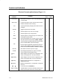
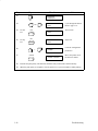
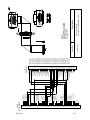
Electrical Controls and Indicators (Figure 1–1)
Switch or
Indicator
Active when printer is:
Online
Offline
Toggles the printer online and offline.
n
n
FF
Advances paper to top of form on next page.
n
n
LF
Advances paper to top of next print line.
Power Switch
Turns printer on and off: 1 = on, 0 = off. This switch is also
a circuit breaker.
Status Lamp
On when the printer is online, off when printer is offline.
Flashes to indicate a fault or warning.
LCD
Liquid Crystal Display. Displays printer status and error
messages.
ON LINE
n
n
n
VIEW
Advances paper for viewing through cover window, then
returns paper to print position.
CLEAR
Clears fault message from LCD after a fault is corrected
and returns printer to off–line state. CLEAR + ENTER
cancels a print job by flushing data from the print buffer.
Clears “PLATEN OPEN” open fault message.
n
R/S
Runs and stops configuration and self tests. Runs and
stops hex dump. Makes a configuration printout when
pressed with “OFFLINE/CONFIG. CONTROL” displayed.
n
Sets location of first line of print on a page.
n
Enters displayed parameter into printer nonvolatile
memory. Must be unlocked before using.
n
SET TOF
ENTER
Y (UP)
Offline: displays next higher level of configuration menu.
Online: moves paper up in 1/72 inch increments.
n
n
B (DOWN)
Offline: displays next lower level of configuration menu.
Online: moves paper down in 1/72 inch increments.
n
n
A (PREV)
Displays previous parameter in a configuration or
diagnostic test menu.
n
" (NEXT)
Displays next parameter in a configuration or diagnostic
test menu.
n
Locks and unlocks the ENTER key.
n
“CANCEL DATA” command. Electrically clears the print
buffer (no printout) and sets TOF at current position.
n
B + Y
CLEAR + ENTER
1–8
Function
Maintenance Overview
(Off) (On)
Power Switch
Status Lamp
CLEAR
UP
R/S
PREV
NEXT
Liquid–Crystal Display
(LCD)
SET TOF
ON LINE
FF
LF
VIEW
ENTER
DOWN
RAISE PRINTER
COVER TO USE
THESE SWITCHES
Figure 1–1. Electrical Controls and Indicators
Maintenance Overview
1–9
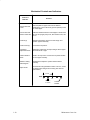
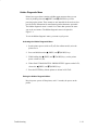
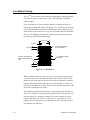
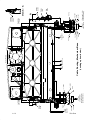
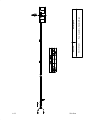
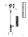
Mechanical Controls and Indicators
Control or
Indicator
Function
Forms Thickness
Lever
Sets the platen for paper and forms of different
thicknesses. Lever must be fully opened (raised) to load
or unload paper.
Forms Thickness
Pointer and Scale
Indicates relative thickness of forms/paper. Set this lever
at A for thin (single–part) forms, B for thicker forms, and
so on.
Tractors (2)
Hold and feed paper. Used to set side margin and
position paper horizontally.
Tractor locks (2)
Lock tractors in position.
Horizontal
Adjustment Knob
Allows fine positioning of left print margin. Moves paper
and tractors left or right.
Vertical Position
Knob
Used to set top of form or first line to be printed. Rotate
to move paper vertically.
Ribbon Loading
Path Diagram
A diagram that helps the operator load the ribbon
correctly.
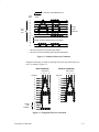
Paper Scale
A horizontal scale graduated in tenths of an inch, useful
for setting paper margins and counting text columns.
(See below.)
1 inch
1
10
0.1 inch
1–10
20
Column
Number
Maintenance Overview
Paper Scale
Left Tractor
Right Tractor
Horizontal
Adjustment
Knob
Tractor
Lock
Vertical
Position
Knob
Tractor
Lock
Ribbon Loading Path
Diagram
Forms Thickness
Lever and Scale
Forms
Thickness
Pointer
Figure 1–2. Mechanical Controls and Indicators
Maintenance Overview
1–11
Tools, Test Equipment, and Supplies
Listed below are the tools and equipment required for field level
maintenance of the printer.
Item
Adapter, 1/4 in. hex to 1/4 in. square, Utica HW–18
Part No.
29–24723–00
Alcohol
Diagonal cutters
Digital voltmeter
ESD Wrist Strap
Extension, 3 in., 3/8 in. drive
Feeler gauge set
Force Gauge, (ChatillonT NY, Gauge–r, 0–20 lb.)
CAT 719–20
Hex bit, 3/16 in., torque screwdriver
29–20995–00
Hex bit, 3/32 in., torque screwdriver
29–18505–00
Hex bit, 5/32 in., torque screwdriver
29–18504–00
Hex bit, 5/64 in., torque screwdriver
Magnet, small
Nut driver set
Pliers, chain nose
Pliers, grip ring
Ratchet, 3/8 in. drive
Ruler, steel, 6 in.
Screwdriver, Allen hex (set), w/extension
Screwdriver, Phillips
Screwdriver, flat tip
Screwdriver, torque, Utica TS–35
29–17381–00
Socket, 7/16 in., 3/8 in. drive
Tie Wraps
Torque Screwdriver Adapter
Tweezers
1–12
Maintenance Overview
2
Scheduled Maintenance
Chapter Contents
Preventive Maintenance Checks and Services . . . . . . . . . . . . . . . . . 2–2
Inspecting the Printer . . . . . . . . . . . . . . . . . . . . . . . . . . . . . . . . . . . . . 2–3
Cleaning the Printer . . . . . . . . . . . . . . . . . . . . . . . . . . . . . . . . . . . . . . 2–4
Cleaning the Cabinet and Print Mechanism . . . . . . . . . . . . . . . . 2–4
Cleaning the Shuttle Frame Assembly . . . . . . . . . . . . . . . . . . . . 2–6
Cleaning the Card Cage Fan Assembly . . . . . . . . . . . . . . . . . . . 2–8
Scheduled Maintenance
2–1
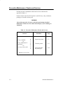
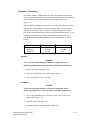
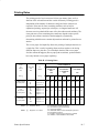
Preventive Maintenance Checks and Services
Perform preventive maintenance checks and services at the intervals
specified in Table 2–1.
Do these checks more often if the printer is used for heavy–duty, continuous
printing or is located in a dusty area.
WARNING
Always disconnect the AC power cord before performing scheduled
maintenance. Failure to do so could result in injury to you or damage to
equipment.
Table 2–1. Preventive Maintenance Checks and Services
Interval
Every 6 months*
—or—
Every 1000 hours of
operation*
—or—
At every service call*
Procedure
Page
Inspect the printer.
2–3
Clean the printer.
2–4
Check and adjust
the platen gap.
4–12
* Whichever occurs first.
2–2
Scheduled Maintenance
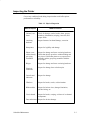
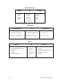
Inspecting the Printer
Correct any condition found during inspection that could affect printer
performance or reliability.
Table 2–2. Physical Inspection
What to Inspect
What to Look For
Cabinet, base,
frame
Check for damage, cracks, breaks, dents, gouges,
scratches, delamination, warping, corrosion, and
proper finish.
Attaching
hardware
Inspect fasteners for thread damage, corrosion.
Nameplates
Inspect for legibility and damage.
Printer cover,
cabinet door(s),
gas spring
assemblies
Inspect for damage and loose or missing hardware.
Check that door(s) open/close without binding and
stay closed. Check that printer cover opens/closes
smoothly and the gas spring assemblies hold the
cover open.
Hinges
Inspect for damage and loose or missing hardware.
Electrical
connectors
Inspect for damage, bent or broken pins.
Controls and
indicators
Inspect for damage.
Windows
Inspect for breaks, cracks, or discoloration.
Ribbon cables
Inspect for broken wires, damaged insulation,
pinched wiring, etc.
Circuit boards
Inspect for breaks, warping, evidence of overheated
components.
Fans and motors Inspect for obvious damage.
Scheduled Maintenance
2–3
Cleaning the Printer
WARNING
Always disconnect the ac power cord before cleaning the printer.
CAUTION
Do not use abrasive cleaners, particularly on the window.
Do not drip water into the printer. Damage to the equipment will result.
Do not spray directly onto the printer when using spray solutions (spray
the cloth, then apply the dampened cloth to the printer).
Do not vacuum the circuit boards.
NOTE: The cleaning procedures in this chapter are the same for all models.
Cleaning the Cabinet and Print Mechanism
1. Power off the printer.
2. Disconnect the ac power cord from the printer and the power source.
3. Remove paper and the ribbon.
4. Wipe down the outside of the cabinet with a clean, lint–free cloth
dampened (not wet) with water and a mild detergent or window cleaning
solution.
5. Dry the outside of the cabinet with a clean, lint–free cloth.
6. Open the printer cover.
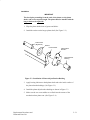
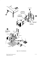
7. Using a soft–bristled, non–metallic brush (such as a toothbrush), brush
paper dust and ribbon lint off the tractors, shuttle cover assembly, base
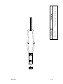
casting, and ribbon guides. Vacuum up the residue. (See Figure 2–1.)
8. Wipe the splined shaft with a soft cloth.
CAUTION
To avoid corrosion damage, use only alcohol when cleaning printer
mechanical elements. Make sure the cleaning solution contains no water.
9. Using a cloth dampened (not wet) with alcohol, clean the ribbon guides.
2–4
Scheduled Maintenance
10. Vacuum up dust and residue from the lower cabinet.
11. Wipe the interior of the lower cabinet with a clean, lint–free cloth
dampened with water and a mild detergent or window cleaning solution.
12. Dry the cabinet interior with a clean, lint–free cloth.
Splined
Shaft
Tractor
Shuttle
Cover
Assembly
Base
Casting
Forms
Thickness
Lever
Ribbon
Guide (2)
Figure 2–1. Cleaning the Print Mechanism
Scheduled Maintenance
2–5
Cleaning the Shuttle Frame Assembly
1. Remove the shuttle cover assembly (page 5–16).
2. Remove the shuttle frame assembly (page 5–42).
3. Remove the paper ironer (page 5–28).
WARNING
Over time, the upper edge of the paper ironer can become sharp. To
avoid cutting yourself, handle the paper ironer on the sides.
4. Moisten a clean, soft cloth with alcohol. Wipe the paper ironer to remove
lint, ink, and paper residue.
5. Install the paper ironer (page 5–28).
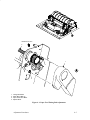
6. Remove the hammer bank cover assembly (page 5–15).
CAUTION
The thin plate (ribbon mask) of the hammer bank cover assembly is
fragile. Be careful not to over–bend or kink the ribbon mask when
handling and cleaning the hammer bank cover assembly.
7. Moisten a clean, soft cloth with alcohol. Wipe the hammer bank cover
assembly to remove lint, ink, and paper residue. Clean the holes in the
cover strips. Carefully open the cover assembly and wipe between the
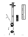
hammer bank cover and the ribbon mask. (See Figure 2–2.)
CAUTION
Do not use any solvents or liquids to clean the hammer tips. Clean the
hammer tips gently—too much pressure can chip hammer tips.
8. Using a stiff, non–metallic brush (such as a toothbrush), gently brush the
hammer tips to remove lint and ink accumulations. Vacuum up any
residue.
CAUTION
The hammer bank contains a strong magnet. To prevent damage to the
hammer tips, do not let the hammer bank cover assembly snap into
place as the hammer bank magnet attracts it. Any impact of the cover
against the hammer bank can break hammer tips.
2–6
Scheduled Maintenance
9. Install the hammer bank cover assembly (page 5–15).
10. Install the shuttle frame assembly (page 5–42).
11. Install the shuttle cover assembly (page 5–16).
12. Clean the card cage fan assembly (page 2–8).
Hammer Bank Cover
(Thick plate)
Ribbon Mask
(Thin plate)
Hammer Bank
Cover Assembly
Alignment Pin (2)
(See below)
Hammer Tip
NOTE:
475 LPM Hammer
Bank shown
Hammer Bank Cover
Alignment Pin
Figure 2–2. Cleaning the Shuttle Frame Assembly
Scheduled Maintenance
2–7
Cleaning the Card Cage Fan Assembly
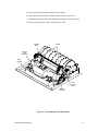
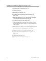
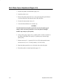
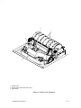
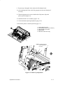
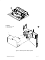
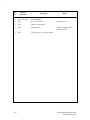
1. Remove the paper path (page 5–29).
2. Vacuum the card cage fan assembly and surrounding areas to remove
paper particles, dust, and lint. (See Figure 2–3.)
3. Install the paper path (page 5–29).
4. Close the printer cover.
5. Connect the ac power cord to the printer and the power source.
Card Cage
Fan Assembly
Figure 2–3. Cleaning the Card Cage Fan Assembly
2–8
Scheduled Maintenance
3
Troubleshooting
Chapter Contents
Introduction . . . . . . . . . . . . . . . . . . . . . . . . . . . . . . . . . . . . . . . . . . . . 3–2
Troubleshooting Aids . . . . . . . . . . . . . . . . . . . . . . . . . . . . . . . . . . . . 3–2
LCD Messages . . . . . . . . . . . . . . . . . . . . . . . . . . . . . . . . . . . . . . . . . . 3–3
Symptoms Not Indicated by Fault Messages . . . . . . . . . . . . . . . . . . 3–29
Troubleshooting Table . . . . . . . . . . . . . . . . . . . . . . . . . . . . . . . . . 3–30
Printer Confidence Check . . . . . . . . . . . . . . . . . . . . . . . . . . . . . . . . . 3–34
Diagnostic Printer Tests . . . . . . . . . . . . . . . . . . . . . . . . . . . . . . . . . . . 3–35
Selecting and Running Diagnostic Printer Tests . . . . . . . . . . . . . 3–37
Hidden Diagnostic Menu . . . . . . . . . . . . . . . . . . . . . . . . . . . . . . 3–39
Hex Code Printout . . . . . . . . . . . . . . . . . . . . . . . . . . . . . . . . . . . . . . . 3–41
ASCII Character Set . . . . . . . . . . . . . . . . . . . . . . . . . . . . . . . . . . 3–43
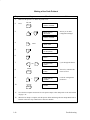
Making a Hex Code Printout . . . . . . . . . . . . . . . . . . . . . . . . . . . 3–42
Troubleshooting
3–1
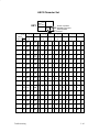
Introduction
This chapter contains procedures for troubleshooting printer malfunctions.
This manual does not cover printer operation or configuration, but you must
operate the printer to check its performance, and sometimes you may have to
reconfigure the printer. Therefore, have the Operator’s Guide and the Setup
Guide handy when you troubleshoot the printer.
Troubleshooting Aids
Troubleshooting is faster and more effective if you understand the equipment
and make use of all available tools. This manual provides a number of
troubleshooting aids to help you isolate printer malfunctions:
3–2
♦
LCD Message Troubleshooting Table (Page 3–3)
A troubleshooting symptom table of fault messages that can appear on
the Liquid Crystal Display (LCD). The fault messages are defined and
solutions provided.
♦
Symptoms Not Indicated by Fault Messages (Page 3–29)
This section summarizes how to troubleshoot problems that are not
indicated by LCD messages. This section includes a logic table for
troubleshooting common problems.
♦
Printer Confidence Check (Page 3–34)
A systematic check of printer operation in the form of a logic table. You
can use this procedure to establish basic printer status or to troubleshoot
imprecise or intermittent symptoms.
♦
Diagnostic Printer Tests (Page 3–35)
A set of printer tests included in the configuration menu structure for use
as diagnostic and maintenance tools.
♦
Hex Code Printout (Page 3–41)
The procedure for printing data streams in hexadecimal format. This
procedure can help you troubleshoot printer data reception problems.
♦
ASCII Character Set (Page 3–43)
A chart of standard ASCII characters and their equivalent codes.
♦
Appendix A: Wire Data
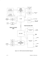
System interconnect and power distribution diagrams, circuit board
pin–outs, and diagrams of the cable assemblies. Use as source material
for tracing electrical problems.
Troubleshooting
LCD Messages
WARNING
Always disconnect the AC power cord from the power source before
doing any maintenance procedure. Failure to remove power could result
in injury to you or damage to equipment. If you must apply power
during maintenance, you will be instructed to so in the maintenance
procedure.
Three kinds of messages appear on the LCD:
♦
Status messages
♦
Operator correctable fault messages
♦
Fault messages that require your attention: the LCD usually indicates
these by adding an asterisk (*) to the message.
If a fault condition occurs, three things happen:
♦
The status lamps on the control panel flash on and off.
♦
The audible alarm sounds if it was enabled. (Press CLEAR to silence the
alarm.)
♦
The control panel LCD displays a fault message.
Clearing LCD Messages
Refer to Table 3–1 and follow the instructions. After correcting an error,
always press the CLEAR key to clear the message and place the printer in
the offline state. (If an error is not cleared, the printer will try to print again
but will display another error message until the error is cleared.)
Troubleshooting
3–3
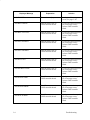
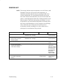
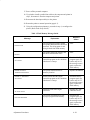
Table 3–1. LCD Message Troubleshooting Table
Displayed Message
Explanation
Solution
8.5V PWR FAIL*
Internal power failure.
Cycle power. If message
recurs, replace one at a time
until message clears:
a) power supply board
b) controller board
15V CTL FAIL*
Controller voltage failure.
Cycle power. If message
recurs, replace one at a time
until message clears:
a) controller board
b) power supply board
23.5V CTL FAIL*
Controller voltage failure.
Cycle power. If message
recurs, replace one at a time
until message clears:
a) controller board
b) power supply board
48V PWR FAIL*
Internal power failure.
Cycle power. If message
recurs, replace one at a time
until message clears:
a) power supply board
b) controller board
A TO D OVERUN*
Fatal firmware error on
CMX controller board.
Cycle power and rerun print
job. If message recurs,
replace CMX controller
board.
ACCESS NULL PTR*
Fatal firmware error on
CMX controller board.
Cycle power and rerun print
job. If message recurs,
replace CMX controller
board.
BUFFER OVERFLOW
Host sends data after the
printer buffer is full. (Serial
interface.)
Page 3–25
CLEAR PAPER JAM
No paper motion.
Clear jam and reload paper.
If message recurs, see page
3–10.
CLOSE PLATEN
The forms thickness lever is
open.
Page 3–11
COIL HOT
One or more hammer coils
are overheating.
Page 3–12
3–4
Troubleshooting
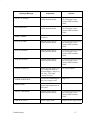
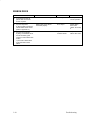
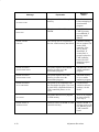
Displayed Message
Explanation
Solution
CTL VOLT FAIL*
Controller voltage failure.
Replace CMX controller
board.
DRVR CIR BAD*
Hammer coil count test
failed.
Page 3–14
EXHAUST FAN FLT
Sensors cannot detect
current in fan circuit.
Page 3–15
FIRMWARE ERROR
Application software tried to
perform an illegal printer
function or damaged
memory detected on CMX
board.
Page 3–16
FRAMING ERROR
Serial framing error. (Serial
interface.)
Page 3–25
HAM. COIL OPEN*
Electrical malfunction of one
or more hammer coils.
Page 3–17
HB NOT INSTLD*
Self–test does not detect
hammer coils.
Page 3–18
HMR BANK FAN FLT
Sensors cannot detect
current in fan circuit.
Page 3–15
ILL EXT BUS ACC*
Fatal firmware error on
CMX controller board.
Cycle power and rerun print
job. If message recurs,
replace CMX controller
board.
ILL INST ACCSS*
Fatal firmware error on
CMX controller board.
Cycle power and rerun print
job. If message recurs,
replace CMX controller
board.
ILLGL OPR ACCSS*
Fatal firmware error on
CMX controller board.
Cycle power and rerun print
job. If message recurs,
replace CMX controller
board.
INTAKE FAN FAULT
Sensors cannot detect
current in fan circuit.
Page 3–15
LO DRV. SHORT *
Circuit(s) on the hammer
bank or in the hammer bank
power cable shorted to
ground.
Page 3–19
Troubleshooting
3–5
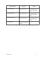
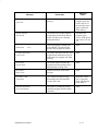
Displayed Message
Explanation
Solution
LOAD PAPER
Printer is out of paper.
Load paper. If message
recurs, see page 3–20.
PAP BAD TABLE*
Fatal firmware error on
CMX controller board.
Cycle power and rerun print
job. If message recurs,
replace CMX controller
board.
PAP BSY TOO LNG*
Fatal firmware error on
CMX controller board.
Cycle power and rerun print
job. If message recurs,
replace CMX controller
board.
PAP FIFO OVERFL*
Fatal firmware error on
CMX controller board.
Cycle power and rerun print
job. If message recurs,
replace CMX controller
board.
PAP FIFO UNDRFL*
Fatal firmware error on
CMX controller board.
Cycle power and rerun print
job. If message recurs,
replace CMX controller
board.
PAP ILLGL ST*
Fatal firmware error on
CMX controller board.
Cycle power and rerun print
job. If message recurs,
replace CMX controller
board.
PAP INCMPL ENER*
Fatal firmware error on
CMX controller board.
Cycle power and rerun print
job. If message recurs,
replace CMX controller
board.
PAP INVLD CMD*
Fatal firmware error on
CMX controller board.
Cycle power and rerun print
job. If message recurs,
replace CMX controller
board.
PAP INVLD PARM*
Fatal firmware error on
CMX controller board.
Cycle power and rerun print
job. If message recurs,
replace CMX controller
board.
PAP NOT SCHED*
Fatal firmware error on
CMX controller board.
Cycle power and rerun print
job. If message recurs,
replace CMX controller
board.
3–6
Troubleshooting
Displayed Message
Explanation
Solution
PAP NT AT SPEED*
Fatal firmware error on
CMX controller board.
Cycle power and rerun print
job. If message recurs,
replace CMX controller
board.
PAP UNEXP INT*
Fatal firmware error on
CMX controller board.
Cycle power and rerun print
job. If message recurs,
replace CMX controller
board.
PARITY ERROR
Parity error. (Serial
interface.)
Page 3–25
PLAT INV CMD*
Fatal firmware error on
CMX controller board.
Cycle power and rerun print
job. If message recurs,
replace CMX controller
board.
PLAT INV PARM*
Fatal firmware error on
CMX controller board.
Cycle power and rerun print
job. If message recurs,
replace CMX controller
board.
PLAT INV STATE*
Fatal firmware error on
CMX controller board.
Cycle power and rerun print
job. If message recurs,
replace CMX controller
board.
POWER SAVER ON
Status message: printer is in
low–energy idle state, all
fans and higher voltages are
off, only +5Vdc logic
circuits are active.
No action required.
POWER SUPPLY HOT
Circuits are overheating on
the power supply board.
Page 3–21
PRINTER HOT
Controller board sensors
report high temperatures on
the board.
Page 3–23
PROTECTED INSTR*
Fatal firmware error on
CMX controller board.
Cycle power and rerun print
job. If message recurs,
replace CMX controller
board.
PWR SUPP VOLT *
Power supply failed.
Replace power supply board.
Troubleshooting
3–7
Displayed Message
Explanation
Solution
RIB INVLD CMD*
Fatal firmware error on
CMX controller board.
Cycle power and rerun print
job. If message recurs,
replace CMX controller
board.
RIB INVLD STATE*
Fatal firmware error on
CMX controller board.
Cycle power and rerun print
job. If message recurs,
replace CMX controller
board.
RIBBON DRIVE
CMX controller does not
detect ribbon drive motor.
Page 3–24
SECURITY VIOLATION
Security code of PAL on
controller board does not
match code of firmware on
the CMX controller board.
Replace the CMX controller
board.
SOFTWARE ERROR *
Application software tried to
perform an illegal printer
function or damaged logic
circuits detected on
controller board.
Page 3–27
SHUTTLE JAM
No shuttle movement or
shuttle moving at wrong
speed.
Page 3–26
SHUTL INV CMD*
Fatal firmware error on
CMX controller board.
Cycle power and rerun print
job. If message recurs,
replace CMX controller
board.
SHUTL INV PARM*
Fatal firmware error on
CMX controller board.
Cycle power and rerun print
job. If message recurs,
replace CMX controller
board.
STACK OVERFLOW*
Fatal firmware error on
CMX controller board.
Cycle power and rerun print
job. If message recurs,
replace CMX controller
board.
STACK UNDERFLOW*
Fatal firmware error on
CMX controller board.
Cycle power and rerun print
job. If message recurs,
replace CMX controller
board.
Cycle power
3–8
Troubleshooting
Displayed Message
Explanation
Solution
TCB CORRUPTED*
Fatal firmware error on
CMX controller board.
Cycle power and rerun print
job. If message recurs,
replace CMX controller
board.
UNDEF INTERRUPT*
Fatal firmware error on
CMX controller board.
Cycle power and rerun print
job. If message recurs,
replace CMX controller
board.
UNDFNED OPCODE*
Fatal firmware error on
CMX controller board.
Cycle power and rerun print
job. If message recurs,
replace CMX controller
board.
UP DRV. SHORT *
Hammer driver circuits on
the CMX boards shorted to
ground.
Page 3–28
Troubleshooting
3–9
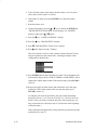
CLEAR PAPER JAM
Instruction
1.
a) Load paper.
b) Press the FF key several
times.
Indication
Yes
No
Forms feed without erratic
motion, noise, or pin–hole
damage.
Go to step 2.
If pin holes are
damaged, go to
step 4. For erratic
motion or noise,
go to step 6.
2.
Press the VIEW key twice.
Forms move correctly in both
directions, without jamming,
tearing, or folding.
Suspect a false
indication. Go to
step 9.
Go to step 3.
3.
Check the platen open belt.
Platen open belt OK.
Replace one at a
time until
message goes
away:
a) platen motor
b) controller board
Replace platen
open belt.
4.
Check that the ribbon mask
has not been deformed in
such a way as to block the
paper path.
Ribbon mask damaged or bent.
Replace the
hammer bank
cover assembly.
Go to step 5.
5.
Check platen gap.
Platen gap incorrect.
Adjust platen gap.
Go to step 6.
Go to step 6.
6.
Check for damage to the
paper feed belt.
Paper feed or belt damaged.
Replace the paper
feed belt. Go to
step 7.
Go to step 7.
7.
Check the tractors and
tractor door springs for
damage or excessive wear.
Tractors are OK.
Replace CMX
controller board.
Go to step 8.
Replace tractors.
8.
Run a print test.
“CLEAR PAPER JAM”
message.
Replace paper
feed motor. Go to
step 9.
Return printer to
normal operation.
9.
a) Load paper.
“CLEAR PAPER JAM”
message.
Clean the paper
motion detector
with cotton swab
and alcohol. Go to
step 10.
Return printer to
normal operation.
“CLEAR PAPER JAM”
message.
Replace the CMX
controller board.
Go to step 11.
Return printer to
normal operation.
“CLEAR PAPER JAM”
message.
Replace paper
detector switch
assembly.
Return printer to
normal operation.
b) Do some line feeds and
run a print test.
10. a) Set the paper motion
detector fault setting to
DISABLE (Ref: Setup Guide).
b) Run a print test and check
paper feeding as the printer
prints.
11. Run a print test.
3–10
Troubleshooting
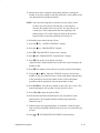
CLOSE PLATEN
Instruction
Indication
Yes
No
1.
Load paper. Close the forms
thickness lever. Run an
operator print test.
“CLOSE PLATEN” message.
Go to step 2.
Return printer to
normal operation.
2.
Power off the printer.
Disconnect the platen
interlock switch connector.
Check the switch with a
meter.
Switch is bad.
Replace platen
interlock switch
assembly.
Replace CMX
controller board.
Troubleshooting
3–11
COIL HOT
NOTE: The printer has sensor circuits that sample the operating temperature
of key print components. When higher than normal temperatures are
sensed, print speed is automatically reduced. If the printer runs at
reduced speed for an extended period of time, a (UNIT) HOT
message is sent to the LCD and printing stops, allowing printer
components to cool down. Pressing the CLEAR key resumes the
print task. If the printer often prints at half speed, it may be
operating in a severe environment. A severe environment is one
with an ambient temperature consistently above 40° Celsius (104°
Fahrenheit) or is dirty enough to create blockage of the cabinet fan
vents. If the printer is located in such an environment, consider
relocating it to a cooler, cleaner area or reducing the size and
duration of the print jobs.
Instruction
Indication
Yes
No
1.
Press the CLEAR key.
“COIL HOT * ” message.
Go to step 2.
Return printer to
normal operation.
2.
Cycle power: Power off
printer. Wait 15 seconds.
Power on printer.
“COIL HOT * ” message.
Go to step 3.
Return printer to
normal operation.
3.
Run “All Black” print test for
1/4 page.
“COIL HOT * ” message.
Go to step 4.
Return printer to
normal operation.
4.
a) Power off the printer.
b) Remove the paper path.
c) Verify that all fan cable
connectors are connected.
(See Appendix A,
Interconnect Diagram.)
Fan cables are properly
connected.
Go to step 6.
Connect fan cable
connector(s).
5.
a) Power on the printer.
b) Verify that all fans operate.
c) Power off printer.
Fans are OK.
Go to step 7.
Replace defective
fan(s).
6.
Check for obstruction of
vents and fan airways.
Vents and airways are clear.
Go to step 8.
Remove
obstructions.
Make sure cabinet
exhaust fan vents
are not blocked.
(Check for items
beneath the
printer blocking
cabinet vents.)
3–12
Troubleshooting
Instruction
Indication
Yes
No
7.
Examine printer environment
for severity. (See NOTE
above.)
Printer environment is OK.
Go to step 9.
Move printer to
cooler, cleaner
location.
8.
Check the kinds of print jobs
the user is running: look for
very dense graphics and
layouts.
Print jobs are dense enough to
slow the printer.
Advise the user to
run jobs in smaller
batches.
Replace one at a
time until the
problem goes
away:
a) shuttle frame
assembly
b) CMX controller
board
Troubleshooting
3–13
DRVR CIR BAD*
Instruction
Indication
Yes
No
1.
Cycle power: Power off
printer. Wait 15 seconds.
Power on printer.
“DRVR CIR BAD*” message.
Go to step 2.
Return printer to
normal operation.
2.
Press the CLEAR key.
“DRVR CIR BAD*” message.
Go to step 3.
Return printer to
normal operation.
3.
a) Power off the printer.
b) Remove the shuttle cover.
c) At the shuttle frame
assembly, disconnect the
hammer bank logic and
power cables.
d) Power on the printer.
“HB NOT INSTALLD*”
message.
Replace the
shuttle frame
assembly.
Replace the CMX
controller board.
3–14
Troubleshooting
(EXHAUST) (HMR BANK) (INTAKE) FAN FLT
Instruction
Indication
Yes
No
1.
Cycle power: Power off
printer. Wait 15 seconds.
Power on printer.
“_____ FAN FLT” message.
Go to step 2.
Return printer to
normal operation.
2.
a) Power off the printer.
b) Remove the paper path.
c) Check that the fan cable
connector is connected. (See
Appendix A, Interconnect
Diagram.)
Fan cable is properly
connected.
Go to step 3.
Connect the fan
cable connector.
3.
Check for obstruction of
vents and fan airway.
Vents and airway are
unobstructed.
Go to step 4.
Remove
obstructions.
Make sure cabinet
exhaust fan vents
are not blocked.
(Check for items
beneath the
printer blocking
cabinet vents.)
4.
a) Power on the printer.
b) Check for rotation of fans
as printer powers up.
c) Power off the printer.
Fans are OK.
Go to step 5.
Replace defective
fan(s).
5.
Power on the printer.
“_____ FAN FLT” message.
Replace CMX
controller board.
Return printer to
normal operation.
Troubleshooting
3–15
FIRMWARE ERROR
Instruction
Indication
Yes
No
1.
Cycle power: Power off
printer. Wait 15 seconds.
Power on printer.
“FIRMWARE ERROR”
message.
Replace the CMX
controller board.
Go to step 2.
Return printer to
normal operation.
2.
a) Power on the printer.
b) Run the print job that was
active when the fault
message first occurred.
“FIRMWARE ERROR”
message.
Application
software error.
Use your local
support procedure
to request
assistance.
Return printer to
normal operation.
3–16
Troubleshooting
HAM. COIL OPEN *
Instruction
Indication
Yes
No
1.
Cycle power: Power off
printer. Wait 15 seconds.
Power on printer.
“HAM. COIL OPEN * ”
message.
Go to step 2.
Return printer to
normal operation.
2.
Press the CLEAR key.
“HAM. COIL OPEN * ”
message.
Replace the
shuttle frame
assembly. Go to
step 3.
Return printer to
normal operation.
3.
a) Power on the printer.
b) Run a diagnostic printer
test.
“HAM. COIL OPEN * ”
message.
Replace the CMX
controller board.
Return printer to
normal operation.
Troubleshooting
3–17
HB NOT INSTLD *
Instruction
Indication
Yes
No
1.
a) Power off the printer.
b) Remove the shuttle cover.
c) Verify that the shuttle
frame assembly is installed.
Shuttle frame assembly is
installed in the printer.
Go to step 2.
Install the shuttle
frame assembly.
2.
a) Remove the paper path.
b) Verify that the hammer
bank logic cable is connected
to connector J108 on the
CMX controller board and to
its connector on the shuttle
frame assembly.
Hammer bank logic cable is
connected to J108 on the
controller board and to the
shuttle frame assembly.
Go to step 3.
Connect hammer
bank logic cable.
Go to step 3.
3.
Power on the printer.
“HB NOT INSTLD * ” message.
Replace the
hammer bank
logic cable. (See
Appendix A.) Go
to step 4.
Return printer to
normal operation.
4.
Power on the printer.
“HB NOT INSTLD * ” message.
Replace the CMX
controller board.
Go to step 5.
Return printer to
normal operation.
5.
Power on the printer.
“HB NOT INSTLD * ” message.
Replace the
shuttle frame
assembly.
Return printer to
normal operation.
3–18
Troubleshooting
LO DRV. SHORT
Instruction
Indication
Yes
No
1.
Cycle power: Power off
printer. Wait 15 seconds.
Power on printer.
“LO DRV. SHORT” message.
Go to step 2.
Return printer to
normal operation.
2.
Press the CLEAR key.
“LO DRV. SHORT” message.
Replace the
shuttle frame
assembly. Go to
step 3.
Return printer to
normal operation.
3.
Power on the printer.
“LO DRV. SHORT” message.
Replace the CMX
controller board.
Go to step 4.
Return printer to
normal operation.
4.
Power on the printer.
“LO DRV. SHORT” message.
Replace hammer
bank logic cable
assembly and
hammer bank
power cable
assembly.
Return printer to
normal operation.
Troubleshooting
3–19
LOAD PAPER
Instruction
Indication
Yes
No
1.
Load paper. Run a diagnostic
printer test.
“LOAD PAPER” message.
Replace paper
detector switch
assembly. Go to
step 2
Return printer to
normal operation.
2.
Run a diagnostic printer test.
“LOAD PAPER” message.
Replace the CMX
controller board.
Return printer to
normal operation.
3–20
Troubleshooting
POWER SUPPLY HOT
NOTE: The printer has sensor circuits that sample the operating temperature
of key print components. When higher than normal temperatures are
sensed, print speed is automatically reduced. If the printer runs at
reduced speed for an extended period of time, a (UNIT) HOT
message is sent to the LCD and printing stops, allowing printer
components to cool down. Pressing the CLEAR key resumes the
print task. Check the operating environment. A severe environment
is one with an ambient temperature consistently above 40° Celsius
(104° Fahrenheit) or is dirty enough to create blockage of the
cabinet fan vents. If the printer is located in such an environment,
consider relocating it to a cooler, cleaner area or reducing the size
and duration of the print jobs.
Instruction
Indication
Yes
No
1.
Press the CLEAR key.
“POWER SUPPLY HOT”
message.
Go to step 2.
Return printer to
normal operation.
2.
Cycle power: Power off
printer. Wait 15 seconds.
Power on printer.
“POWER SUPPLY HOT ”
message.
Go to step 3.
Return printer to
normal operation.
3.
Run a diagnostic printer test.
“POWER SUPPLY HOT”
message.
Go to step 4.
Return printer to
normal operation.
4.
a) Power off the printer.
b) Remove the paper path.
c) Check that the power
supply guard/air deflector is
correctly positioned over the
power supply board.
d) WARNING: DO NOT
TOUCH the power supply,
but hold your hand close
enough to check for heat
radiating off the board.
Power supply is noticeably hot.
Go to step 5.
Replace power
supply board.
5.
Verify that all fan cable
connectors are connected.
(See Appendix A,
Interconnect Diagram.)
Fan cables are properly
connected.
Go to step 6.
Connect fan cable
connector(s).
6.
a) Power on the printer.
b) Verify that all fans operate.
c) Power off printer.
Fans are OK.
Go to step 7.
Replace defective
fan(s).
Troubleshooting
3–21
Instruction
Indication
Yes
No
7.
Check for obstruction of
vents and fan airways.
Vents and airways are clear.
Go to step 8.
Remove
obstructions.
Make sure cabinet
exhaust fan vents
are not blocked.
(Check for items
beneath the
printer blocking
cabinet vents.)
8.
Examine printer environment
for severity. (See NOTE
above.)
Printer environment is OK.
Go to step 9.
Move printer to
cooler, cleaner
location.
9.
Check the kinds of print jobs
the user is running: look for
very dense graphics and
layouts.
Print jobs are dense enough to
slow the printer.
Advise the user to
run jobs in smaller
batches.
Replace the CMX
controller board.
3–22
Troubleshooting
PRINTER HOT
NOTE: This message indicates internal temperatures over 60° Celsius (140°
Fahrenheit). Print jobs will not create such temperatures, so
immediately determine that the fans are operating and that all air
vents are unobstructed. It is crucial that the exhaust vents on the
floor of the cabinet remain unblocked, since hot air from inside the
printer is vented through the cabinet floor. Nothing should be stored
under the printer. Then check the operating environment. A severe
environment is one with an ambient temperature consistently above
40° Celsius (104° Fahrenheit) or is dirty enough to create blockage
of the cabinet fan vents. If the printer is located in such an
environment, consider relocating it to a cooler, cleaner area or
reducing the size and duration of the print jobs.
Instruction
Indication
Yes
No
1.
Press the CLEAR key.
“MECH DRIVER HOT” or
“PRINTER HOT” message.
Go to step 2
Return printer to
normal operation.
2.
Cycle power: Power off
printer. Wait 15 seconds.
Power on printer.
“MECH DRIVER HOT” or
“PRINTER HOT” message.
Go to step 3
Return printer to
normal operation.
3.
Verify that all fans operate.
Fans are OK.
Go to step 4
Replace defective
fan(s).
4.
a) Power off the printer.
b) Check for obstruction of
vents and fan airways.
Vents and airways are clear.
Go to step 5
Remove
obstructions.
Make sure cabinet
exhaust fan vents
are not blocked.
(Check for items
beneath the
printer blocking
cabinet vents.)
5.
Examine printer environment
for severity. (See NOTE
above.)
Printer environment is OK.
Replace the CMX
controller board.
Move printer to
cooler, cleaner
location.
Troubleshooting
3–23
RIBBON DRIVE
Instruction
Indication
Yes
No
1.
Cycle power: Power off
printer. Wait 15 seconds.
Power on printer.
“RIBBON DRIVE” message.
Go to step 2.
Return printer to
normal operation.
2.
a) Power off printer.
b) Check cable connections
of both ribbon driver motors.
(Refer to Appendix A.)
Ribbon drive motor cables
connected properly.
Go to step 3.
Attach ribbon
drive motor
cables. Go to step
3.
3.
a) Power on the printer.
b) Using a screwdriver, short
across the ribbon guide
screws to reverse ribbon hub
motion.
c) Check for a ribbon drive
motor that will not wind
ribbon.
Both motors wind the ribbon.
Replace the CMX
controller board.
Replace defective
ribbon drive motor.
3–24
Troubleshooting
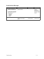
Serial Interface Messages
Instruction
1.
a) Make a configuration
printout. (Ref.: Setup Guide)
Indication
Yes
Host and printer serial interface
parameters match.
Go to step 2
Set printer serial
interface
parameters to
match those of the
host. (Ref.: Setup
Guide)
Job prints OK and no serial
interface fault messages
appear.
Return printer to
normal operation.
Replace the CMX
controller board.
b) Verify that host and printer
serial interface configuration
settings match for:
— Baud Rate
— Data Bits
— Stop Bits
— Parity
2.
Send a print job to the printer.
Troubleshooting
No
3–25
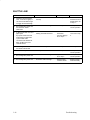
SHUTTLE JAM
Instruction
Indication
Yes
No
1.
Check the forms thickness
lever: if it is set too tightly, it
can slow the shuttle enough
to trigger the fault message.
Forms thickness lever set
correctly.
Go to step 2.
Set forms
thickness lever for
thicker paper. Go
to step 2.
2.
Run a diagnostic printer test
and check for shuttle
obstruction.
“SHUTTLE JAM” message.
Go to step 3.
Return printer to
normal operation.
3.
a) Remove shuttle cover and
paper path.
b) Inspect shuttle area and
mechanism for obstruction.
c) Check that cable
connectors are attached at
MPU, shuttle motor, and
controller board.
Shuttle movement blocked or
cable(s) loose/disconnected.
Remove
obstruction.
Connect cable(s).
Go to step 4.
Install shuttle
cover. Go to step
4.
4.
Run a diagnostic shuttle test
and observe the shuttle.
Shuttle runs slowly.
Go to step 5.
Go to step 7.
5.
Check MPU adjustment.
MPU adjustment OK.
Go to step 6.
Return printer to
normal operation.
6.
Run a diagnostic printer test.
“SHUTTLE JAM” message.
Replace the MPU.
Go to step 7.
Return printer to
normal operation.
7.
Run a diagnostic printer test.
“SHUTTLE JAM” message.
Replace CMX
controller board.
Replace shuttle
frame assembly.
3–26
Troubleshooting
SOFTWARE ERROR *
Instruction
Indication
Yes
No
1.
Cycle power: Power off
printer. Wait 15 seconds.
Power on printer.
“SOFTWARE ERROR * ”
message.
Go to step 2
Return printer to
normal operation.
2.
Disconnect the input data line
from the host computer.
Cycle power: Power off
printer. Wait 15 seconds.
Power on printer.
“SOFTWARE ERROR * ”
message.
Replace the CMX
controller board.
Not a printer
problem.
Application
software error.
Request
assistance from
your local support
group. Return
printer to normal
operation.
Troubleshooting
3–27
UP DRV. SHORT
Instruction
Indication
Yes
No
1.
Cycle power: Power off
printer. Wait 15 seconds.
Power on printer.
“UP DRV. SHORT” message.
Go to step 2.
Return printer to
normal operation.
2.
Press the CLEAR key.
“UP DRV. SHORT” message.
Replace the CMX
controller board.
Go to step 3.
Return printer to
normal operation.
3.
Power on the printer.
“UP DRV. SHORT” message.
Replace the
shuttle frame
assembly. Go to
step 4.
Return printer to
normal operation.
4.
Power on the printer.
“UP DRV. SHORT” message.
Replace hammer
bank logic cable
assembly and
hammer bank
power cable
assembly.
Return printer to
normal operation.
3–28
Troubleshooting
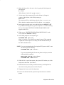
Symptoms Not Indicated by Fault Messages
Use standard fault–isolation techniques to troubleshoot malfunctions not
indicated by fault messages. These techniques are summarized below:
1. Ask the operator to describe the problem.
2. Verify the fault by running diagnostic tests or replicating conditions
reported by the user.
3. Look for a match in the “Symptoms Not Indicated by Fault Messages
Troubleshooting Table” on page 3–30, and follow the instructions given.
4. Locate the malfunction using the half–split method:
a. Start at a general level and work down to details.
b. Isolate faults to half the remaining system at a time, until the final
half is a field–replaceable part or assembly. (Troubleshooting aids
are listed on page 3–2.)
5. Replace the defective part or assembly.
IMPORTANT
DO NOT attempt field repairs of electronic components or assemblies.
Replace a malfunctioning electronic assembly with an operational spare.
Most electronic problems are corrected by replacing the printed circuit
board assembly, sensor, or cable that causes the fault indication. The
same is true of failures traced to the hammer bank: replace the entire
shuttle frame assembly. It is not field repairable.
6. Test printer operation after every corrective action.
7. Stop troubleshooting and return the printer to normal operation when the
reported symptoms disappear.
Troubleshooting
3–29
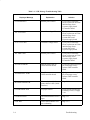
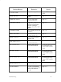
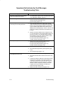
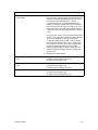
Symptoms Not Indicated by Fault Messages
Troubleshooting Table
Symptom
Instruction
No power, control panel LCD and LEDs
blank, card cage fan not running.
1.
+5 volt distribution problem to the controller board. (See
Power Distribution Diagram, page A–3.)
Power on hang condition.
1.
Replace one at a time until the problem is fixed:
a) CMX controller board (page 5–10)
b) power supply (page 5–12)
Blank or single line of black squares
across top row of control panel LCD.
1.
Power off printer. Remove the paper path. Check all
cable connections into the controller board, especially
that the control panel cable is seated in connector J110
on the controller board. Make sure the flash memory
SIMM(s) is/are seated properly in J10/J11. Power on the
printer. If the display is still blank or has a black line, go
to step 2
2.
(NOTE: If the panel is blank but the cooling fans come
on, the control panel or control panel cable is bad. If the
fans do not come on, the controller board is probably
bad.) Replace one at a time until the problem is fixed:
a) control panel assembly (page 5–14)
b) control panel cable assembly (page 5–14)
c) CMX controller board (page 5–10)
Control panel key failure.
1.
Replace one at a time until the problem is fixed:
a) control panel assembly (page 5–14)
b) control panel cable assembly (page 5–14)
c) CMX controller board (page 5–10)
Ribbon folding or feed problems.
1.
Clean the shuttle frame assembly (page 2–6)
2.
Check the left and right ribbon guide alignment (page
4–16)
3.
Check the platen gap (page 4–12)
1.
Perform a printer confidence check (page 3–34)
2.
Check the host data cable connection at the rear of the
printer.
3.
If the printer interface is RS–232, interchange the wires
to pins 2 and 3. This is the most common cause of a
completely inoperative RS–232 cable. Make sure the
printer and host have the same baud rate, number of
data bits, number of stop bits, and parity. In RS–232,
configure the host for XON/XOFF if possible; this
requires the least complex cable.
4.
Replace the CMX controller board (page 5–10)
Printer appears normal, but does not
print data sent from the host.
3–30
Troubleshooting
Symptom
Printer prints data sent from the host, but
occasionally prints double characters,
random ! or * characters, or loses blocks
of data.
Instruction
1.
If the printer prints from the host, but occasionally loses
blocks of data, the most likely cause is the host not
responding to “send no more data” signals from the
printer. With a Centronics interface, this means the host
is ignoring BUSY; in RS–232, the host is ignoring the
XOFF character or “Data Terminal Ready” signal (pin
20). Sometimes the cable is not conveying the
necessary signals. Test this by using a serial line
analyzer and software or test equipment that displays
the data and handshake lines of the printer. A breakout
box works, but will not debug XON/XOFF or other
RS–232 data protocols. If the printer is sending XOFF
with one stop bit, the host may not be receiving it if the
host requires 1.5 or 2 stop bits.
2.
a) If the printer prints from the host, but occasionally
prints double characters, there is probably a noise
problem at the interface or the host computer is sending
an inverted strobe. This problem can occur on
Centronics interfaces, never on RS–232. What happens
is the strobe signal registers logic 1 more than once for a
certain character. To fix this, change the strobe to trailing
edge or invert the strobe polarity. (Refer to the User’s
Guide.)
b) Also check that the terminating resistors are present
on the controller board (page 5–35). You can correct
some noise problems by using a shielded data cable or
by changing the terminating resistors. The standard
terminating resistors are optimized for high speed data
transfer for cables between 1 and 5 meters long; you
can change them for slower operation, which will provide
slightly more noise immunity.
c) Noise is caused by static, a floating logic ground,
unshielded cable, changes in ground voltage from
nearby equipment, or capacitively– or
magnetically–induced noise. On very long cables,
capacitively–induced noise from the other signals of the
cable (especially Centronics “ACK”) can cause false
strobes. Unshielded and flat ribbon cables are much
more prone to problems due to increased length. The
best solution is to shorten cable, shield it, and reduce
local electromagnetic noise. Also, make sure that both
the printer and the host computer are properly grounded.
Troubleshooting
3–31
Print Quality Problems
Missing, light, or smeared characters or
dots:
All characters or dots are too light or too
dark.
1.
Check the forms thickness lever setting.
2.
Check the ribbon for folds or tears.
3.
Clean the shuttle frame assembly (page 2–6).
4.
Check the platen gap adjustment (page 4–12).
5.
Replace one at a time until problem is fixed:
a) shuttle frame assembly (page 5–42)
b) controller board (page 5–10)
1.
Check the forms thickness lever setting.
2.
Clean the shuttle frame assembly (page 2–6).
3.
Check the platen gap adjustment (page 4–12).
4.
Install a new ribbon.
5.
Replace one at a time until problem is fixed:
a) controller board (page 5–10)
b) shuttle frame assembly (page 5–42)
Horizontal misalignment. (Dots or
1.
characters move left or right from dot row
to dot row or line to line.)
2.
If dots between alternate dot rows are misaligned, check
hammer phasing (page 4–25).
Clean the shuttle frame assembly (page 2–6).
3.
Check the MPU gap adjustment (Ref: page 5–20).
4.
Replace one at a time until problem is fixed:
a) MPU (page 5–20)
b) controller board (page 5–10)
c) shuttle frame assembly (page 5–42)
Vertical misalignment:
1. Dots or characters move up or down
from dot row to dot row or line to line.
2. Incorrect spacing from dot row to dot
row or line to line.
1.
Check paper feed motor belt (page 4–4).
2.
Check platen gap adjustment (page 4–12).
3.
Replace one at a time until problem is fixed:
a) tractors (page 5–50)
b) controller board (page 5–10)
c) paper feed motor (page 5–23)
d) power supply board (page 5–12)
Randomly misplaced dots.
1.
Check platen gap adjustment (page 4–12).
2.
Check printer grounding.
3.
Replace one at a time until problem is fixed:
a) controller board (page 5–10)
b) power supply board (page 5–12)
c) shuttle frame assembly (page 5–42)
3–32
Troubleshooting
Print Quality Problems
Garbled print or paper slews
uncontrollably.
1.
a) Put the printer in hex dump mode and analyze the
binary data. One cause of garble is the host interface or
cable not transmitting all 8 data bits. When this occurs,
the Centronics interface receives a 1 on every
unconnected data line. Uncontrolled slewing is often
caused by enabling PI (Paper Instruction) in the printer
when the host lacks a PI signal. (PI shows as “p” on the
hex dump printout.) Some RS–232 interfaces only send
7 data bits. In this case, the eighth bit will be received as
a one.
b) In RS–232, a common cause of garble is the interface
set to the wrong baud rate or parity. Sometimes the host
sends 1.5 or 2 stop bits; in this case, the printer’s
“1–stop–bit” setting will accept both 1.5 and 2 stop bit
data. Sometimes the data may “fade” or “persist” from
one character to the next. This reveals a problem with
Centronics terminating resistors on the controller
board—especially if they are absent. Garble also can
result from failed terminating resistors or parallel logic,
but this is rare.
2.
Replace the controller board.
Missing print over a single hammer’s
zone.
1.
Replace one at a time until problem is fixed:
a) shuttle frame assembly (page 5–42)
b) controller board (page 5–10)
Missing print over every 4th hammer’s
zone.
1.
Replace one at a time until problem is fixed:
a) controller board (page 5–10)
b) shuttle frame assembly (page 5–42)
No hammers fire but paper advances.
1.
Replace one at a time until problem is fixed:
a) controller board (page 5–10)
b) shuttle frame assembly (page 5–42)
Troubleshooting
3–33
Printer Confidence Check
Instruction
Indication
Yes
No
1.
Check that printer is plugged
into correct power source.
Power cable installed correctly
to proper source.
Power off printer.
Go to step 2.
Power off the
printer. Connect
printer to correct
power source.
2.
Power on the printer.
Printer initializes correctly and
goes to online or offline state,
depending on power–up
configuration.
Go to step 3
Troubleshoot the
fault message
(page 3–3).
3.
Run an operator print test
(page 3–35).
Printer operates correctly.
Go to step 4
Troubleshoot the
fault message
(page 3–3).
4.
Make a configuration printout.
(Refer to the Setup Guide.)
a) Configuration is correct for
the user’s application.
b) Host computer and printer
are using the same protocol
(emulation).
c) Configuration has not been
inadvertently changed by user.
Go to step 5
Reconfigure the
printer. (Refer to
the Setup Guide.)
5.
a) Power off the printer.
b) Check alignments and
adjustments. (See Chapter
4.)
Assemblies and components
are adjusted in accordance with
Chapter 4.
Go to step 6
Adjust all
assemblies that
are out of spec.
6.
a) Power off the printer.
b) Remove paper path (page
5–29).
c) Check all electrical
connections.
Connections are clean and tight.
Wires are not stripped, frayed,
or out of connectors.
Go to step 7
Replace stripped,
frayed, or broken
wires.
7.
Check that printed circuit
boards are correctly installed
and cable connections are
correct. (See Appendix A.)
Printed circuit boards are
correctly installed and all cables
are correctly attached.
Go to step 8
Install each board
correctly. Check
and correct the
cable
attachments.
8.
Inspect for debris that could
cause short circuits (loose
fasteners, foil, etc.).
Metallic debris found.
Remove debris.
Clean the printer.
(Chapter 2.)
Go to step 9
9.
a) Install paper path (page
5–29).
b) Power on the printer.
Printer powers up and initializes
properly.
Printer appears to
be OK. Fault may
not be in printer.
Check host
computer,
applications
software, interface
cabling, etc.
Troubleshoot the
fault message
(page 3–3).
3–34
Troubleshooting
Diagnostic Printer Tests
A set of printer tests is included in the configuration menu structure for use
as diagnostic and maintenance tools. You can use these printer tests to check
the print quality and basic operation of the printer. In addition, you will use
some of these tests in various troubleshooting and adjustment procedures.
The diagnostic printer tests are summarized below:
Troubleshooting
♦
Shift Recycle A “sliding” alphanumeric pattern useful for identifying
missing or malformed characters, improper vertical alignment, or vertical
compression.
♦
All E’s A pattern of all uppercase letter E’s useful for identifying
missing characters, misplaced dots, smeared characters, improper
phasing, or light/dark character variations.
♦
E’s + TOF A pattern of all E’s repeated for ten lines and followed by a
form feed to the top of the next page. This test is useful for identifying
paper motion or paper feed problems.
♦
All H’s A pattern of all uppercase letter H’s useful for detecting missing
characters or dots, smeared characters, or improper phasing.
♦
Underline Only An underline pattern useful for identifying hammer
bank misalignment.
♦
All Black Prints all dot positions, creating a solid black band. Exercises
shuttle and hammer bank at maximum capacity.
♦
Shuttle Slow Verifies proper operation by exercising the shuttle and
ribbon mechanisms at low speed. You can also use this test to check
ribbon tracking and reversing.
♦
Shuttle Fast Verifies proper operation by exercising the shuttle and
ribbon mechanisms at high speed. You can also use this test to check
ribbon tracking and reversing.
♦
Shuttle Only This test runs only the shuttle mechanism, not the ribbon
mechanism.
3–35
3–36
♦
Phase Printer A hammer timing test that permits you to adjust the
hammer phase value. The hammer phase value is a timing parameter that
controls the vertical alignment of dots in character printing. The
numerical units are relative; they do not represent a physical
measurement or value. There is no “correct” value or range. The factory
prints the initial phase value on the aluminum casting of the shuttle
assembly, next to the motor housing. Use this value as your starting point
when adjusting hammer phasing.
♦
Paperout Adj. This test prints a vertical comb pattern. You will use this
pattern when you do the end of forms (paper out) adjustment procedure.
The comb pattern lets you measure the number of dot rows from the
completion of a paper out fault to the end of the paper.
♦
Burnin Test Use of this test is not recommended. This test is used by
the printer manufacturer to burn in the printer prior to shipment, and has
no value as a maintenance tool.
Troubleshooting
Selecting and Running Diagnostic Printer Tests
Step
Key
Result
1.
a) Load paper.
b) Install the ribbon.
c) Set top–of–form. (Refer to the Operator’s Guide.)
2.
Press:
ON LINE
3.
+
Notes
OFFLINE
CONFIG. CONTROL
The printer must be offline
to select diagnostic tests.
ENTER SWITCH
UNLOCKED
Allows you to make
configuration changes.
OFFLINE
CONFIG. CONTROL
4.
UNTIL
5.
DIAGNOSTICS
Printer Tests
6.
UNTIL
7.
10.
11.
Troubleshooting
DIAGNOSTICS
Test Width
Test Width
Full Width*
8.
9.
OFFLINE
DIAGNOSTICS
OR
ENTER
Test Width
X
Test Width
X*
UNTIL
DIAGNOSTICS
Test Width
UNTIL
DIAGNOSTICS
Printer Tests
Cycle through the choices.
X = Full Width or
X = 80 columns.
Test width selected.
3–37
Step
Key
Result
12.
Printer Tests
Shift Recycle*
13.
OR
14.
To start
test:
R/S
15.
To stop
test:
R/S
16.
17.
Notes
Printer Tests
All E’s*
Printer Tests
All E’s*
+
CLEAR
Printer Tests
All E’s
Cycle through the choices.
Refer to page 3–35.
The test runs.
Stops tests.
ENTER SWITCH
LOCKED
Locks the configuration
parameters.
OFFLINE
CONFIG. CONTROL
Moves the printer out of
the menus to offline.
18.
Examine the print quality. The characters should be fully formed and of uniform density.
19.
When the print quality is acceptable, close the printer cover; press ON LINE to enable printing.
3–38
Troubleshooting
Hidden Diagnostic Menu
Printer boot–up software contains a hidden menu structure that you can
access by holding down the A (PREV) and B (DOWN) keys while
powering up the printer. These menus are not intended for the end user, but
provide useful information for manufacturing and maintenance personnel.
The hidden diagnostic menu is a multi–level menu that operates the same
way as the user menus. The hidden diagnostic menu is depicted in
Figure 3–1.
To exit the hidden diagnostic menu, you must recycle power.
Activating the Hidden Diagnostic Menu
1. Set the printer power switch to O (off). On cabinet models, raise the
printer cover.
2. Press and hold down the A (PREV) and B (DOWN) keys.
3. While holding the A (PREV) and B (DOWN) keys, set the printer
power switch to 1 (on).
4. When “BOOT DIAGNOSTICS / PRESS ENTER” appears on the LCD,
release the A (PREV) and B (DOWN) keys.
5. Press the ENTER key. Menu options are shown in NO TAG.
Exiting the Hidden Diagnostic Menu
Recycle power: power off the printer, wait 15 seconds, the power on the
printer.
Troubleshooting
3–39
BOOT DIAGNOSTICS
PRESS ENTER
B (DOWN)
BOOT DIAGNOSTICS
VERSION CHECK
B (DOWN)
VERSION CHECK
BOOT VERSION
B (DOWN)
BOOT/CMX V100H
12Sep95 #154669
VERSION CHECK
SOFTWARE VERSION
09/08/95
11:41:08
VERSION CHECK
EC VERSION
EC V1.00H
07Sep95 #154643
VERSION CHECK
ASIC VERSIONS
VX VERSION=F
MECA VERSION=F
" (NEXT)
" (NEXT)
BOOT DIAGNOSTICS
FILE UTILITIES
B (DOWN)
FILE UTILITIES
VIEW FILES
B (DOWN)
VIEW FILES
FILE NAME
" (NEXT)
FILE UTILITIES
FILE SYSM
FLASHDISK STATUS
FREE = 0012473
FLASHDISK STATUS
#ERASES = 000073
" (NEXT)
" (NEXT)
FLASHDISK STATUS
# OF FILES = 000
FLASHDISK STATUS
USED = 0002048
FLASHDISK STATUS
DELETED = 0000000
BOOT DIAGNOSTICS
MISC UTILITIES
B (DOWN)
MISC UTILITIES
DISPLAY MEMORY
B (DOWN)
FLASH = 2 MBYTES
DRAM = 2 MBYTES
MISC UTILITIES
RESET PRINTER
RESETTING...
PLEASE WAIT
MISC UTILITIES
COPY FLASH SIMMS
LOADING PROGRAM
INTO FLASH
MISC UTILITIES
COPY BOOT SIMMS
LOADING PROGRAM
INTO FLASH
MISC UTILITIES
RUN MEMORY TESTS
TESTING FOR
ADDRESS SHORTS
MISC UTILITIES
FILE DOWNLOAD
WAITING FOR
PROGRAM DOWNLOAD
" (NEXT)
NOTE: To exit this
menu, cycle power.
Figure 3–1. Diagnostics Menu
3–40
Troubleshooting
Hex Code Printout
A hex code printout (“hex dump”) lists each ASCII data character received
from the host computer and lists its corresponding two-digit hexadecimal
code. (See Figure 3–2.) Hex dumps can be used to troubleshoot some types
of printer data reception problems.
Every printable character prints both as its assigned symbol and as its hex
equivalent. Every nonprintable (ASCII control) character prints both as a
period (.) and as its hex equivalent. When using a parallel interface, the letter
“p” before a hex code indicates an active Paper Instruction (PI) line and a
blank space before a hex code indicates an inactive PI line.
To make a hex code printout, refer to the procedure on page 3–42. To convert
an ASCII character to its corresponding hex code (or vice-versa), refer to the
ASCII code chart on page 3–43.
Figure 3–2. Hex Dump Sample
Troubleshooting
3–41
Making a Hex Code Printout
Step
Key
Result
1.
Make sure the printer is on. Raise the printer cover.
2.
Press:
ON LINE
3.
Notes
OFFLINE
CONFIG. CONTROL
+
ENTER SWITCH
UNLOCKED
Allows you to make
configuration changes.
OFFLINE
CONFIG. CONTROL
4.
UNTIL
5.
MAINT / MISC
Hex Dump Mode
6.
Hex Dump Mode
Disable
7.
8.
OR
ENTER
9.
10.
OFFLINE
MAINT / MISC
+
ON LINE
Hex Dump Mode
Enable
Cycle through the choices.
Hex Dump Mode
Enable *
Asterisk (*) indicates this
choice is active.
ENTER SWITCH
LOCKED
Locks the configuration
parameters.
ONLINE
11.
Go to the host computer and send a file. The printer outputs a hex dump. Refer to the ASCII chart
on page 3–43.
12.
When the hex dump is complete, take the printer offline and change the Hex Dump Mode back to
Disable. Follow the steps outlined above and select Disable.
3–42
Troubleshooting
ASCII Character Set
B7
0
B6
KEY
B6
0
0
B5
BITS
0
0
1
B4 B3 B2 B1
1 0
B7
0
B5
BITS
0
1
0
1
1
OCTAL equivalent
DECIMAL equivalent
HEX equivalent
ASCII Character
33
27
1B
ESC
1
0
1
0
1
0
1
1
0
0
1
1
1
1
0
1
1
COLUMN
0
B4 B3 B2 B1 ROW
1
0 0 0 0
0
NUL
0
0
0
0 0 0 1
1
SOH
1
1
1
0 0 1 0
2
STX
2
2
2
DC2
0 0 1 1
3
ETX
3
3
3
0 1 0 0
4
EOT
0 1 0 1
5
0 1 1 0
DLE
DC1
(XON)
2
20
16
10
21
17
11
SP
!
3
40
32
20
41
33
21
4
0
60
48
30
1
61
49
31
5
6
@
100
64
40
P
120
80
50
A
101
65
41
Q
121
81
51
a
7
140
96
60
p
160
112
70
141
97
61
q
161
113
71
22
18
12
”
42
34
22
2
62
50
32
B
102
66
42
R
122
82
52
b
142
98
62
r
162
114
72
(XOFF)
23
19
13
#
43
35
23
3
63
51
33
C
103
67
43
S
123
83
53
c
143
99
63
s
163
115
73
4
4
4
DC4
24
20
14
$
44
36
24
4
64
52
34
D
104
68
44
T
124
84
54
d
144
100
64
t
164
116
74
ENQ
5
5
5
NAK
25
21
15
%
45
37
25
5
65
53
35
E
105
69
45
U
125
85
55
e
145
101
65
u
165
117
75
6
ACK
6
6
6
SYN
26
22
16
&
46
38
26
6
66
54
36
F
106
70
46
V
126
86
56
f
146
102
66
v
166
118
76
0 1 1 1
7
BEL
7
7
7
ETB
27
23
17
47
39
27
7
67
55
37
G
107
71
47
W
127
87
57
g
147
103
67
w
167
119
77
1 0 0 0
8
BS
10
8
8
CAN
30
24
18
(
50
40
28
8
70
56
38
H
110
72
48
X
130
88
58
h
150
104
68
x
170
120
78
1 0 0 1
9
HT
11
9
9
EM
31
25
19
)
51
41
29
9
71
57
39
I
111
73
49
Y
131
89
59
i
151
105
69
y
171
121
79
1 0 1 0
10
LF
12
10
0A
SUB
32
26
1A
*
52
42
2A
:
72
58
3A
J
112
74
4A
Z
132
90
5A
j
152
106
6A
z
172
122
7A
1 0 1 1
11
VT
13
11
0B
ESC
33
27
1B
+
53
43
2B
;
73
59
3B
K
113
75
4B
[
133
91
5B
k
153
107
6B
{
173
123
7B
1 1 0 0
12
FF
14
12
0C
FS
34
28
1C
54
44
2C
<
74
60
3C
L
114
76
4C
\
134
92
5C
l
154
108
6C
|
174
124
7C
DC3
15
35
’
,
–
55
=
75
M
115
1 1 0 1
13
CR
1 1 1 0
14
SO
16
14
0E
RS
36
30
1E
.
56
46
2E
>
76
62
3E
N
116
78
4E
1 1 1 1
15
SI
17
15
0F
US
37
31
1F
/
57
47
2F
?
77
63
3F
O
117
79
4F
Troubleshooting
13
0D
GS
29
1D
45
2D
61
3D
77
4D
]
^
_
135
93
5D
m
155
109
6D
}
175
125
7D
136
94
5E
n
156
110
6E
~
176
126
7E
137
95
5F
o
157
111
6F
DEL
177
127
7F
3–43
3–44
Troubleshooting
4
Adjustment Procedures
Chapter Contents
Preparing the Printer for Maintenance . . . . . . . . . . . . . . . . . . . . . . . . 4–2
Returning the Printer to Normal Operation . . . . . . . . . . . . . . . . . . . . 4–3
Belt, Paper Feed Timing, Adjustment . . . . . . . . . . . . . . . . . . . . . . . . 4–4
Belt, Platen Open, Adjustment . . . . . . . . . . . . . . . . . . . . . . . . . . . . . 4–6
Paper Drive Motor Pulley Alignment . . . . . . . . . . . . . . . . . . . . . . . . 4–8
Paper Scale Alignment . . . . . . . . . . . . . . . . . . . . . . . . . . . . . . . . . . . 4–10
Platen Gap Adjustment . . . . . . . . . . . . . . . . . . . . . . . . . . . . . . . . . . . 4–12
Platen Open Motor Pulley Alignment . . . . . . . . . . . . . . . . . . . . . . . . 4–14
Ribbon Guide Alignment . . . . . . . . . . . . . . . . . . . . . . . . . . . . . . . . . . 4–16
Splined Shaft Skew Adjustment . . . . . . . . . . . . . . . . . . . . . . . . . . . . 4–18
Adjusting the End of Forms Distance . . . . . . . . . . . . . . . . . . . . . . . . 4–20
Hammer Phasing Adjustment . . . . . . . . . . . . . . . . . . . . . . . . . . . . . . 4–25
Installing Software . . . . . . . . . . . . . . . . . . . . . . . . . . . . . . . . . . . . . . . 4–27
Adjustment Procedures
4–1
Preparing the Printer for Maintenance
WARNING
Unplug the printer power cord from the power outlet before you do any
maintenance procedure. Failure to remove power could result in injury
to you or damage to equipment. If you must apply power during
maintenance, you will be instructed to so in the maintenance procedure.
Always do the following before performing any maintenance:
1. Set the printer power switch to O (off).
2. Unplug the printer power cord from the AC power source.
3. Unload paper.
4. Read the entire maintenance procedure before you begin working on the
printer.
5. Gather the necessary parts before you begin work.
4–2
Adjustment Procedures
Returning the Printer to Normal Operation
When you have finished servicing the printer, restore it to operation by
following the steps below:
1. Install the ribbon.
2. Plug the AC power cord into the printer and the power source.
3. Set the printer power switch to | (on).
4. Load paper.
5. Close the cabinet doors and the printer cover.
6. Test printer operation by selecting and running one of the diagnostic
print tests. (See Chapter 3.)
7. Select the emulation. (Refer to the Operator’s Guide or the Setup Guide.)
8. Set the top–of–form. (Refer to the Operator’s Guide or the Setup Guide.)
Adjustment Procedures
4–3
Belt, Paper Feed Timing, Adjustment (Figure 4–1)
1. Prepare the printer for maintenance (page 4–2).
2. Open the printer cover.
3. Remove the paper path (page 5–29).
4. Loosen four screws and remove the barrier shield (page 5–59,
Figure 5–10).
5. Remove the timing belt cover (1) by squeezing the top and bottom to
release the plastic tabs from the slots in the side plate.
6. Loosen (do not remove) the motor mount bolts (2).
7. Using the straight end of a force gauge, apply 15 pounds (66.7 N) of
pressure to the paper feed drive motor (3). Use the splined shaft (4) to
steady the gauge.
8. Reduce tension to 12 pounds (53.4 N) and torque the paper feed motor
mount bolts (2) to 18 ± 2 inch–pounds (2.03 ± 0.23 NSm).
9. Snap the timing belt cover (1) into the slots in the side plate.
10. Install the barrier shield and tighten the four screws (page 5–59,
Figure 5–10).
11. Install the paper path (page 5–29).
12. Return the printer to normal operation (page 4–3).
4–4
Adjustment Procedures
Direction of Force
4
1
2
3
2
1.
2.
3.
4.
Timing Belt Shield
Motor Mount Bolt (2)
Paper Feed Drive Motor
Splined Shaft
Figure 4–1. Paper Feed Timing Belt Adjustment
Adjustment Procedures
4–5
Belt, Platen Open, Adjustment (Figure 4–2)
1. Prepare the printer for maintenance (page 4–2).
2. Open the printer cover.
3. Remove the platen open belt cover (1) by squeezing the top and bottom
to release the plastic tabs from the slots in the side plate.
4. Loosen the motor mount screws (2).
5. Close the forms thickness lever all the way.
CAUTION
Too much tension on the platen open belt can cause the platen gap to
change, which can lead to premature wear of the platen, damaged
hammer tips, and poor print quality.
6. Using a force gauge, apply 10 ± 1 pounds (44.48 ± 4.45 N) of tension to
the shank of the platen drive pulley (3), pushing away from the large
platen pulley.
7. Reduce tension to 5 ± 1 pounds (22.24 ± 4.45 N) and torque the motor
mount screws (2) to 11 ± 2 inch–pounds (1.24 ± 0.23 NSm).
8. Snap the platen open belt cover (1) into the slots in the side plate.
9. Return the printer to normal operation (page 4–3).
4–6
Adjustment Procedures
1. Belt Cover
2. Motor Mount Screw
3. Platen Open Motor Shaft
2
Direction of Force
1
3
2
Figure 4–2. Platen Open Belt Adjustment
Adjustment Procedures
4–7
Paper Drive Motor Pulley Alignment (Figure 4–3)
1. Prepare the printer for maintenance (page 4–2).
2. Open the printer cover.
3. Remove the timing belt cover (1) by squeezing the top and bottom to
release the plastic tabs from the slots in the side plate.
4. Loosen the screw (2) in the motor pulley collar (3).
5. Align the paper drive motor pulley (4) with the splined shaft pulley (5).
CAUTION
Make sure there is at least 0.040 inches (1.016 mm) of clearance between
the collar (3) and the motor face plate.
6. Hold the collar (3) flush against the motor pulley (4) and tighten the
screw (2).
7. Check for correct tension on the paper feed timing belt (page 4–4).
Adjust if necessary.
8. Snap the timing belt cover (1) into the slots in the side plate.
9. Return the printer to normal operation (page 4–3).
4–8
Adjustment Procedures
5
2
4
1
3
1.
2.
3.
4.
5.
Belt Shield
Cap Screw
Motor Pulley Collar
Motor Pulley
Splined Shaft Pulley
Figure 4–3. Paper Drive Motor Pulley Alignment
Adjustment Procedures
4–9
Paper Scale Alignment (Figure 4–4)
1. Load paper and ribbon.
2. Connect the power cord to the AC power source.
3. Set the printer power switch to 1 (on).
4. Open the printer cover.
5. Verify that the shuttle cover (1) is properly installed (page 5–16).
6. Print a full 132 column line by selecting and running one of the
diagnostic self–tests. (See Chapter 4.)
7. Check alignment of the scale to the print at column positions 1 and 132.
8. If adjustment is necessary, loosen the three button–head 5/64 inch hex
screws (2).
9. Position the scale (3) so that column positions 1 and 132 line up with the
first and last characters on the 132 character printout.
10. Tighten the button–head screws (2).
11. Close the printer cover.
4–10
Adjustment Procedures
3
2
2
1
1. Shuttle Cover
2. Screw, Button–Head, 5/64 inch hex (3)
3. Paper Scale
Figure 4–4. Paper Scale Alignment
Adjustment Procedures
4–11
Platen Gap Adjustment (Figure 4–5)
IMPORTANT
Only do this procedure if the original equipment shuttle frame assembly
or platen has been replaced by a new or refurbished unit.
1. Prepare the printer for maintenance (page 4–2).
2. Open the printer cover.
3. Remove the shuttle cover assembly (page 5–16).
4. Remove the ribbon.
5. Loosen the platen open belt (page 4–6, steps 3 and 4).
6. Raise the forms thickness lever (1) to the fully open position.
CAUTION
Do not force the platen against the feeler gauge. Damage to the hammer
tips will result.
NOTE: The platen gap on the LG04 printer (0.011 inch) differs from the
platen gap on the LG06 printer (0.010 inch).
7. Insert a 0.011 inch (0.28 mm) flat feeler gauge (2) straight down between
the hammer bank cover plate (3) and ribbon mask (4), within four
hammer positions of the left end of the hammer bank.
CAUTION
Adjust the platen set screws less than 1/4 turn on one side, then check
the other side. Adjustment sensitivity is approximately 0.03 inch per
revolution of the set screw. Also, insert the feeler gauge no more than 2
inches down from the top of the ribbon mask.
8. Gently close the forms thickness lever (1). As the platen is closing,
gently slide the feeler gauge up and down, keeping it between the
hammer tip and ribbon mask. If the feel is too tight when the platen is
being closed, adjust the set screw (5) at the end of the platen
counterclockwise. If the feel is too loose, adjust the set screw clockwise.
With the forms thickness lever closed all the way, the feeler gauge should
contact both the tips and the ribbon mask and move with light friction.
Shift the gauge slightly to verify.
4–12
Adjustment Procedures
9. Repeat steps 6 through 8 at the right end of the hammer bank.
10. After adjusting both sides, check the gap again at both ends. Readjust if
necessary.
11. When the platen gap is correct at both ends of the platen, adjust the
platen open belt (page 4–6).
12. Install the shuttle cover assembly (page 5–16).
13. Check the hammer phasing adjustment (page 4–25).
14. Return the printer to normal operation (page 4–3).
1.
2.
3.
4.
5.
Forms Thickness Lever
Feeler Gauge (0.011 inch or 0.28 mm)
Hammer Bank Cover Plate
Ribbon Mask
Set Screw, 3/32 inch hex (2)
1
5
NOTE: Left side adjustment
shown. Right side is
the same.
2
3
4
Figure 4–5. Platen Gap Adjustment
Adjustment Procedures
4–13
Platen Open Motor Pulley Alignment (Figure 4–6)
1. Prepare the printer for maintenance (page 4–2).
2. Open the printer cover.
3. Remove the platen open belt cover (1) by squeezing the top and bottom
to release the plastic tabs from the slots in the side plate.
4. Loosen the set screw (2) in the motor pulley.
5. Bottom out the platen open motor pulley (3) on the motor shaft and
torque the set screw (2) to 9 ± 2 inch–pounds (1.02 ± 0.23 NSm).
6. Check the platen open belt tension (page 4–6). Adjust if necessary.
7. Snap the platen open belt cover (1) into the slots in the side plate.
8. Return the printer to normal operation (page 4–3).
4–14
Adjustment Procedures
1.
2.
3.
4.
Belt Cover
Set Screw
Platen Open Motor Pulley
Platen Shaft Pulley
2
1
3
4
Figure 4–6. Platen Open Motor Pulley Alignment
Adjustment Procedures
4–15
Ribbon Guide Alignment (Figure 4–7)
1. Open the printer cover.
2. Load paper and install the ribbon. To adjust the left ribbon guide, the
ribbon should have a full spool on the right hub (1).
3. Run a ribbon and shuttle diagnostic self–test. (See Chapter 4.)
4. To adjust the left ribbon guide, momentarily short between the left
ribbon guide skid screws (2) to assure right to left motion of the ribbon.
5. Observe how the ribbon (3) is passing around the left ribbon guide (4). It
should be centered and not folding against either of the two white nylon
washers.
6. If the ribbon is not centered, loosen the retaining screws (5) just enough
so that the ribbon guide (4) can be rotated to new positions, but remains
in place once moved.
7. Rotate the ribbon guide (4) as necessary to center the ribbon (3).
8. Observe how the ribbon (3) is winding on the left spool (6). If the ribbon
is interfering with the flange of the spool, make sure the ribbon hub and
spool are mounted correctly.
9. Tighten the screws (5).
10. Allow most of the ribbon to accumulate on the left spool (6). Repeat
steps 3 through 9 for the right ribbon guide (7).
4–16
Adjustment Procedures
6
1
2
4
3
7
5
3
1.
2.
3.
4.
5.
6.
7.
Right Hub
Screw, Left Ribbon Guide Skid (2)
Ribbon
Ribbon Guide, Left
Screw, Retaining (2)
Left Ribbon Spool
Ribbon Guide, Right
Figure 4–7. Ribbon Guide Alignment
Adjustment Procedures
4–17
Splined Shaft Skew Adjustment (Figure 4–8)
If lines of print are not parallel with the edge perforations on the paper,
perform the following adjustment.
1. Prepare the printer for maintenance (page 4–2).
2. Loosen the screw (1) securing the adjusting link (2).
3. Adjust the link (2) by raising or lowering the horizontal adjustment knob
(3) to obtain print parallel with paper perforations. Tighten the screw (1).
4. Return the printer to normal operation (page 4–3).
4–18
Adjustment Procedures
1
3
2
1. Screw
2. Adjusting Link
3. Horizontal Adjustment Knob
Figure 4–8. Splined Shaft Skew Adjustment
Adjustment Procedures
4–19
Adjusting the End of Forms Distance
This procedure tests and sets the distance from the page perforation at which
a LOAD PAPER message is triggered. This adjustment prevents printing on
the platen when the printer runs out of paper.
The measurement units are dot rows. You will use the dot row patterns
printed by the Paper Out Dots printer test to verify that this parameter is set
correctly.
NOTE: Do this procedure only if a new paper detector switch assembly has
been installed, or if you are sure that the end of forms adjustment is
incorrect. A paper out triggering distance of 1 or 2 dot rows from
the perforation is acceptable; 5 to 7 dot rows off indicates
adjustment is required.
Also, although it is not required, it is advisable to test the paper out
triggering distance with 6-part paper, in order to verify correct
printing with multi-part forms.
The procedure below describes how to run the Paper Out Dots printer test
and modify the paper out adjustment value.
1. Power on the printer.
2. Load paper and set the top of form. Make sure the forms thickness lever
is closed.
3. On cabinet models, open the cabinet front door.
4. On the sheet of paper just below the paper entrance slot, tear a four-inch
square on the left side, immediately below the perforation. (See
Figure 4–9.) This creates a hole that will trigger a PAPER EMPTY fault
message, but allows printing to the right of the hole (which would
normally be on the platen).
4–20
Adjustment Procedures
Page Perforation
Page Perforation
4 in.
4 in.
Page Perforation
Figure 4–9. Paper Preparation for Paper Out Adjustment Test
Adjustment Procedures
4–21
5. Tear a four inch square in the manner described above, on every third
sheet, until you have made 3 or 4 holes.
6. If the printer is online, press the ON LINE key to place the printer
offline.
7. Raise the printer cover.
8. On the control panel, press the Y + B keys to unlock the ENTER key.
“ENTER SWITCH UNLOCKED” briefly displays. (If “LOCKED”
displays, simply press Y + B again.)
9. Press the B key. “CONFIG CONTROL” displays.
10. Press the A key. “DIAGNOSTICS” displays.
11. Press B. “DIAGNOSTICS / Printer Tests” displays.
12. Press " until “Paper Out Adj.” displays.
This test will print a vertical “comb” pattern at around column 70, each
long bar separated by three shorter bars. An enlarged example of the
comb pattern is shown below.
13. Press ENTER until the Paper Out Dots test starts. The comb pattern will
print until the display shows “END OF FORMS / LOAD PAPER” and (if
enabled) the audible alarm sounds. If the alarm sounds, press CLEAR to
silence it.
14. Remove the paper from the tractors and examine the area of the page
perforation. (If the alarm sounds when you open the platen, press
CLEAR to silence it.)
If a long bar just meets the perforation, the end of forms adjustment
distance is correct. (1 or 2 dot rows off is OK; 5 to 7 dot rows off is too
much.) Unless you wish to restart the procedure with 6-part paper, you
may stop the test here, and skip to step 27 (See the note at the beginning
of this procedure.)
If the comb pattern stopped short of the perforation or printed beyond the
perforation, go to step 15
4–22
Adjustment Procedures
15. Measure how short or long the comb pattern printed by counting the
number of dot rows needed to reach the perforation, or the number of dot
rows that printed beyond the perforation.
NOTE: You can use the long bars to count the dot rows quickly. There
are three dot rows between each long bar, so each long bar
increases the number of dot rows by four. You can also tear off
a small piece of the comb pattern from the beginning of the
pattern and use it as a ruler to help you measure the dot rows
required either to reach the perforation or back up to it.
16. Reload the paper and set the top of form.
17. Press the B key. “CONFIG CONTROL” displays.
18. Press the A key. “DIAGNOSTICS” displays.
19. Press B. “DIAGNOSTICS / Printer Tests” displays.
20. Press " until “DIAGNOSTICS / Paperout Dots” displays.
21. Press B. The top line of the display will show
“Paperout Dots” and the bottom line will show the current setting for the
number of dots.
22. Press B. The number of dots will move up to the top line of the display.
23. Using the " or A key, adjust the XX DOTS value up or down by the
number of dots you counted in step 15 (If the comb pattern stopped short
of the perforation, increase the number of dots. If the comb pattern
printed beyond the perforation, decrease the number of dots.)
24. Press ENTER to select the new number of dots as the active value. (The
asterisk that appears tells you that it is now the active value.)
25. Press CLEAR to place the printer offline.
26. Run the Paper Out Dots and the Paperout Adj. tests until the comb
pattern prints at an acceptable distance from the page perforation.
(Return to step 9)
27. When the paper out triggering distance is acceptable, reload the paper,
feed it past any remaining unused holes that you tore in it, and set the top
of form.
28. Press Y + B. “ENTER SWITCH LOCKED” briefly displays.
Adjustment Procedures
4–23
29. Close the printer cover.
30. Press the ON LINE key to place the printer online.
4–24
Adjustment Procedures
Hammer Phasing Adjustment
You must check and adjust hammer phasing if the CMX controller board is
replaced, the shuttle frame assembly is removed, or if the MPU is replaced.
The hammer phase value is a timing parameter that permits you to adjust the
vertical alignment of dots in character printing. The phase value numerical
units are relative; they do not represent a physical measurement or value.
Thus there is no “correct” value or range.
The factory prints the initial phase value on the aluminum casting of the
shuttle assembly, next to the motor housing. Adjust the phasing to this value
and recheck the vertical alignment. When vertical alignment is acceptable,
write the new phasing value on the shuttle.
Phasing should be adjusted with the printer printing at full paper width.
IMPORTANT
The printer must be printing the Phase pattern of “H’s” when the
Phasing Value is changed, or the New Phasing Value will not be written
into NVRAM. If the value is changed when not printing, the printer will
return to its default phasing value when powered off then back on.
The procedure is as follows:
1. Power on the printer.
2. Install the ribbon.
3. Load full width (132 column) paper and set the top of form.
4. If the printer is online, press the ON LINE key to place the printer
offline.
5. Raise the printer cover.
6. On the control panel, press the Y + B keys to unlock the ENTER key.
“ENTER SWITCH UNLOCKED” briefly displays. (If “LOCKED”
displays, simply press Y and B again.)
7. Press the B key. “CONFIG CONTROL” displays.
8. Press the A key until “DIAGNOSTICS” displays.
9. Press B. “DIAGNOSTICS / Printer Tests” displays.
Adjustment Procedures
4–25
10. Press B. “Printer Tests / Shift Recycle” displays.
11. Press A until “Printer Tests / Phase Printer” displays.
12. Press ENTER. The top line of the display will show “Phase Printer” and
the bottom line will show the current phasing index value.
13. Press ENTER. The phasing index value (followed by an asterisk) will
move up to the top line of the display. The printer begins printing all Hs,
each line preceded by the phasing index value.
14. Press " or A to increase or decrease the phasing index value, then press
ENTER to activate the value as it prints. Continue to increase or
decrease the phasing index value until the pattern of Hs appears as shown
below:
Needs
Adjustment
Correct
Needs
Adjustment
15. When the print pattern is acceptable, press ENTER. Printing stops, and
the printer automatically enters the current phasing index value into
NVRAM.
16. Press Y + B. “ENTER SWITCH LOCKED” briefly displays.
17. Close the printer cover.
18. Press the ON LINE key to place the printer online.
NOTE: If you changed the phasing value, power down the printer, remove
the shuttle cover, and write the new phase value on the aluminum
shuttle casting.
4–26
Adjustment Procedures
Installing Software
Flash memory is contained in one or two single in–line memory modules
(SIMMs) located on the controller board. Printer emulation and operating
system software are loaded into flash memory at the factory, but you will
install software in the following situations:
♦
The customer needs to upgrade printer software
♦
The customer needs different emulation software
♦
You have replaced the controller board
♦
You have added or replaced flash memory
Emulation and operating system software are stored as a compressed file on a
3.5 inch, double–density floppy diskette. The file is “executable”: you will
expand it, convert it to binary, and copy it into printer flash memory with a
single command.
1. Make a printout of all saved configurations. (Refer to the Setup Guide.)
(Installing new software erases all saved configurations. You will use the
printouts to restore printer configuration.)
2. Connect the parallel data cable to the default parallel port (LPT1) of an
IBM or IBM–compatible personal computer using the PC–DOS or
MS–DOS operating system.
NOTE: You can connect the cable to the LPT2 port if the LPT1 port is
already in use. You can also download software through the printer
serial port. (The serial port is hard–wired at 9600 baud, 8 data bits, 1
stop bit, no parity.) The download commands are different if you
use these ports, as described in the note after step 12.
3. Connect the parallel data cable to the parallel port of the printer.
4. Plug the AC power cord into the printer and the power source.
5. Power on the personal computer.
6. If the computer is running Windows 3.x, double–click on the MSDOS
icon to obtain a DOS prompt.
7. Insert the emulation or upgrade diskette into diskette drive A (or B) of
the personal computer.
Adjustment Procedures
4–27
8. Make the diskette drive the active drive by typing the following at the
DOS prompt:
A:<return>
(If the diskette is in drive B, type B:<return>)
9. Get the name of the compressed file on the diskette by listing the
contents of the diskette; at the DOS prompt type:
DIR<return>
The compressed file on the diskette takes the form FILENAME.EXE
Write down the complete name of the file with the .EXE extension.
10. On the printer operator panel, press and hold down the ONLINE + FF
keys. Without releasing the keys, power the printer on. Continue holding
the keys down until “WAITING FOR PROGRAM DOWNLOAD”
appears on the LCD.
11. When you see “WAITING FOR PROGRAM DOWNLOAD” on the
LCD, release the ONLINE + FF keys.
12. At the DOS prompt on the computer type:
FILENAME.EXE –pb<return>
where FILENAME.EXE is the file you noted in step 9. This command
expands the file and copies it as a binary file into the flash memory on
the CMX controller board.
NOTE: If you are downloading the file using the LPT2 port on the PC, enter
the following DOS command:
FILENAME.EXE –pb 2 <Return>
If you are downloading the file into the printer serial port, enter the
following DOS commands:
MODE COM1:9600,N,8,1,P<Return>
FILENAME.EXE –PBC1<Return>
13. While the file is copied into memory, the printer LCD informs you of the
load process and status. (See Table 1.)
14. When the file has successfully loaded into memory and the printer has
reset itself, set the printer power switch to O (off).
15. Unplug the AC power cord from the printer.
16. Remove the diskette from the personal computer and store it with the
printer.
4–28
Adjustment Procedures
17. Power off the personal computer.
18. If you had to install a parallel data cable to the computer and printer in
step 2, disconnect it from the computer and printer.
19. Reconnect the data input cable(s) to the printer.
20. Return the printer to normal operation (page4–3).
21. Using the configuration printout(s) you made in step 1, reconfigure the
printer. (Refer to the Setup Guide.)
Table 1. Flash Memory Message Guide
Message
CLEARING PROGRAM
FROM FLASH
DIAGNOSTIC
PASSED
ERROR: DC PROGRAM
NOT VALID
ERROR: DRAM AT
ADDRESS XXXXXXXX
ERROR: EC PROGRAM
NOT VALID
ERROR: EC STOPPED
AT STATE XXXX
ERROR: FLASH
DID NOT PROGRAM
Adjustment Procedures
Explanation
Required
Action
The program successfully loaded
into printer RAM and the checksum
matched. The old program is now
being deleted from flash memory.
None
The printer passed its memory and
hardware initialiazation tests.
None
Printer cannot find the data
controller program or the validation
checksum is corrupt.
Download the DC
program again. Go
back to step 10. If
the message occurs
again, replace the
flash memory.
The printer found a defective
memory location.
Replace the DRAM.
Printer cannot find the engine
controller program or the validation
checksum is corrupt.
Download the EC
program again. Go
back to step 10. If
the message occurs
again, replace the
flash memory.
Hardware fault in the engine
controller.
Replace the CMX
controller board.
The printer encountered an error
trying to program flash memory.
Download the
program again. Go
back to step 10. If
the message occurs
again, replace the
flash memory.
4–29
Message
ERROR: FLASH
NOT DETECTED
ERROR: NO DRAM
DETECTED
ERROR: NVRAM
FAILURE
ERROR: PROGRAM
NEEDS MORE DRAM
ERROR: PROGRAM
NEEDS MORE FLASH
ERROR: PROGRAM
NOT COMPATIBLE
ERROR: PROGRAM
NOT VALID
ERROR: SHORT AT
ADDRESS XXXX
4–30
Required
Action
Explanation
The printer could not find any flash
memory.
Install flash memory
before attempting to
download this
program.
The printer could not find any
DRAM.
Check DRAM on
CMX. If present,
reseat DRAM, If
missing, install
DRAM.
The security PAL is not present or
the non–volatile memory has failted.
Check the security
PAL at location U54
on the CMX
controller. If the
PAL is absent,
install PAL. If
security PAL is
present, replace the
CMX controller
board. (Do NOT
attempt to replace
NVRAM.)
The printer requires more DRAM
memory in order to run the
downloaded program.
Add DRAM or use a
smaller emulation
program.
The printer requires more flash
memory in order to run the
downloaded program.
Add flash memory
or use a smaller
emulation program.
The printer is not compatible with
the downloaded program. User tried
to load CMX–compatible diskette in
CBO–controlled printer, or vice
versa.
Use the correct
emulation software
option(s) for this
model.
The printer does not see a program
in flash memory.
There is no program
in printer memory.
Go to step 2.
Hardware failure in DRAM or CMX
controller circuitry.
Replace DRAM. If
message occurs with
new DRAM, replace
CMX controller
board.
Adjustment Procedures
Message
ERROR: WRITING
TO FLASH
ERROR: WRONG
CHECKSUM
LOADING PROGRAM
FROM PORT
XX%
LOADING PROGRAM
INTO FLASH
RESETTING . . .
PLEASE WAIT
RESTORING
BOOT CODE
SECURITY CODE
VIOLATION
SENDING PROGRAM
TO EC PROCESSOR
Adjustment Procedures
Explanation
Required
Action
Hardware or software fault in flash
memory.
Download the
program again. Go
back to step 10. If
the message occurs
again, replace the
flash memory.
The printer received the complete
program but the checksum did not
match. The data were corrupted
during download.
Download the
program again:
Power off the printer
and start over at step
10.
The new program is loading into
printer RAM. XX indicates how
much of the program has loaded.
None
The printer has deleted the previous
program from flash memory and is
loading the new program into flash
memory.
None
The printer finished loading the
program into flash memory and is
automatically resetting itself.
None
Normal download initialization
message.
None
The software running or being
downloaded does not match the
security PAL code.
Install the correct
PAL or program.
(PAL and program
must match.)
The printer is loading the engine
controller program into the engine
controller.
None
4–31
4–32
Adjustment Procedures
5
Replacement Procedures
and Illustrated Parts List
Chapter Contents
Organization of This Chapter . . . . . . . . . . . . . . . . . . . . . . . . . . . . . . 5–4
Section I: Replacement Procedures . . . . . . . . . . . . . . . . . . . . . . . . 5–4
Belt, Paper Feed Timing . . . . . . . . . . . . . . . . . . . . . . . . . . . . . . . . . . 5–5
Belt, Platen Open . . . . . . . . . . . . . . . . . . . . . . . . . . . . . . . . . . . . . . . . 5–7
Cable Connectors and Connector Shells . . . . . . . . . . . . . . . . . . . . . . 5–8
Circuit Board: CMX Controller . . . . . . . . . . . . . . . . . . . . . . . . . . . . . 5–10
Circuit Board: Power Supply . . . . . . . . . . . . . . . . . . . . . . . . . . . . . . . 5–12
Circuit Breaker . . . . . . . . . . . . . . . . . . . . . . . . . . . . . . . . . . . . . . . . . . 5–13
Control Panel Assembly . . . . . . . . . . . . . . . . . . . . . . . . . . . . . . . . . . 5–14
Cover Assembly, Hammer Bank / Ribbon Mask . . . . . . . . . . . . . . . . 5–15
Cover Assembly, Shuttle . . . . . . . . . . . . . . . . . . . . . . . . . . . . . . . . . . 5–16
Fan Assembly, Card Cage . . . . . . . . . . . . . . . . . . . . . . . . . . . . . . . . . 5–17
Fan Assembly, Cabinet Exhaust . . . . . . . . . . . . . . . . . . . . . . . . . . . . 5–18
Fan Assembly, Hammer Bank . . . . . . . . . . . . . . . . . . . . . . . . . . . . . . 5–19
Magnetic Pick–up (MPU) Assembly . . . . . . . . . . . . . . . . . . . . . . . . . 5–20
Memory Modules and Security PAL . . . . . . . . . . . . . . . . . . . . . . . . . 5–21
Motor Assembly, Paper Feed . . . . . . . . . . . . . . . . . . . . . . . . . . . . . . . 5–23
Motor Assembly, Platen Open . . . . . . . . . . . . . . . . . . . . . . . . . . . . . . 5–25
Motor Assembly, Ribbon Drive . . . . . . . . . . . . . . . . . . . . . . . . . . . . . 5–27
Paper Ironer . . . . . . . . . . . . . . . . . . . . . . . . . . . . . . . . . . . . . . . . . . . . 5–28
Replacement Procedures and
Illustrated Parts List
5–1
Paper Path . . . . . . . . . . . . . . . . . . . . . . . . . . . . . . . . . . . . . . . . . . . . . 5–29
Platen . . . . . . . . . . . . . . . . . . . . . . . . . . . . . . . . . . . . . . . . . . . . . . . . . 5–30
Resistors, Terminating . . . . . . . . . . . . . . . . . . . . . . . . . . . . . . . . . . . . 5–35
Ribbon Guide Assembly (L/R) . . . . . . . . . . . . . . . . . . . . . . . . . . . . . 5–37
Ribbon Hub . . . . . . . . . . . . . . . . . . . . . . . . . . . . . . . . . . . . . . . . . . . . 5–38
Shaft, Splined . . . . . . . . . . . . . . . . . . . . . . . . . . . . . . . . . . . . . . . . . . . 5–39
Shaft, Support . . . . . . . . . . . . . . . . . . . . . . . . . . . . . . . . . . . . . . . . . . 5–41
Shuttle Frame Assembly . . . . . . . . . . . . . . . . . . . . . . . . . . . . . . . . . . 5–42
Spring Assembly, Gas . . . . . . . . . . . . . . . . . . . . . . . . . . . . . . . . . . . . 5–44
Spring, Extension, Hammer Bank . . . . . . . . . . . . . . . . . . . . . . . . . . . 5–45
Switch Assembly, Paper Detector . . . . . . . . . . . . . . . . . . . . . . . . . . . 5–46
Switch Assembly, Platen Interlock . . . . . . . . . . . . . . . . . . . . . . . . . . 5–48
Tractor (L/R) . . . . . . . . . . . . . . . . . . . . . . . . . . . . . . . . . . . . . . . . . . . 5–50
5–2
Replacement Procedures and
Illustrated Parts List
Section II: Illustrated Parts List . . . . . . . . . . . . . . . . . . . . . . . . . . . . 5–51
Figure 5–7. Top Cover, Doors, and Casters . . . . . . . . . . . . . . . . . . . . 5–53
Figure 5–8. Paper Fence and Chains . . . . . . . . . . . . . . . . . . . . . . . . . 5–55
Figure 5–9. Operator Panel and Cabinet Details . . . . . . . . . . . . . . . . 5–57
Figure 5–10. Covers . . . . . . . . . . . . . . . . . . . . . . . . . . . . . . . . . . . . . 5–59
Figure 5–11. Print Mechanisms and Circuit Boards . . . . . . . . . . . . . 5–61
Figure 5–12. Magnetic Pickup Unit (MPU) and Extension Spring . . 5–63
Figure 5–13. Tractor Shafts . . . . . . . . . . . . . . . . . . . . . . . . . . . . . . . . 5–65
Figure 5–14. Platen . . . . . . . . . . . . . . . . . . . . . . . . . . . . . . . . . . . . . . 5–67
Figure 5–15. Motors, Fans, and Paper Detector Switch . . . . . . . . . . 5–69
Figure 5–16. Circuit Breaker . . . . . . . . . . . . . . . . . . . . . . . . . . . . . . . 5–71
Replacement Procedures and
Illustrated Parts List
5–3
Organization of This Chapter
This chapter is divided into two sections.
♦
Section I: Replacement Procedures
This section consists of written procedures for removing and
installing the components that are replaceable at the field service
level of maintenance. Section I begins on this page.
The removal/installation procedures in this section will refer you to
the illustrations in Section II.
♦
Section II: Illustrated Parts List
This section consists of drawings of all the assemblies comprising
the printer. On the left page facing each illustration is a list of the
parts that are illustrated and their part numbers. Section II begins
with a list of figures on page 5–51.
In the parts lists, Ref means “Shown for reference only: the
component is part of another assembly, is shown for clarity, or is not
spared.”
Section I: Replacement Procedures
WARNING
Unplug the printer power cord from the power outlet before doing any
maintenance procedure. Failure to remove power could result in injury
to you or damage to equipment. Only apply power during maintenance
if you are instructed to do so in a maintenance procedure.
IMPORTANT
The components specified in this chapter are field replaceable units
(FRUs). FRUs must be repaired at the factory. Do not try to repair these
items in the field.
DO NOT attempt field repairs of electronic components or assemblies.
Do not de–solder any circuit board components. Replace a
malfunctioning electronic assembly with an operational spare. Most
electronic problems are corrected by replacing the printed circuit board,
sensor, or cable that causes the fault indication. The same is true of
failures traced to the hammer bank: replace the entire shuttle frame
assembly. It is not field repairable.
5–4
Replacement Procedures and
Illustrated Parts List
Belt, Paper Feed Timing
Removal
1. Prepare the printer for maintenance (page 4–2).
2. Open the printer cover.
3. Remove the paper path (page 5–29).
4. Remove four screws, the barrier shield, and the anti–static brush (page
5–59, Figure 5–10).
5. Remove the timing belt cover by squeezing the top and bottom to release
the plastic tabs from the slots in the side plate (page 5–59, Figure 5–10).
6. Loosen (do not remove) the 7/64 inch setscrew in the paper feed motor
pulley collar.
7. Loosen (do not remove) the two 5/16 inch paper feed motor mount
screws (page 5–69, Figure 5–15).
8. Remove the paper feed timing belt by sliding the paper feed motor pulley
off the motor shaft and the belt off the splined shaft pulley.
Replacement Procedures and
Illustrated Parts List
5–5
Installation
1. Install the paper feed timing belt over the splined shaft pulley and the
motor pulley. Slide the motor pulley onto the paper feed motor shaft.
2. Holding a 0.040 inch feeler gauge between the pulley collar and the
motor body, torque the 7/64 inch collar screw to 25 ± 2 inch–pounds
(2.82 ± 0.23 NSm).
3. Using the straight end of a force gauge, apply 12 pounds (53.38 N) of
pressure to the paper feed drive motor. Use the splined shaft to steady the
gauge.
4. Reduce pressure to 9 pounds (40.03 N) and torque the 5/16 inch paper
feed motor mount screws to 18 ± 2 inch–pounds (2.03 ± 0.23 NSm).
5. Snap the timing belt cover into the slots in the side plate (page 5–59,
Figure 5–10).
NOTE: The anti–static brush bristles must face downward.
6. Install the barrier shield, anti–static brush, and four screws (page 5–59,
Figure 5–10).
7. Install the paper path (page 5–29).
8. Return the printer to normal operation (page 4–3).
5–6
Replacement Procedures and
Illustrated Parts List
Belt, Platen Open
Removal
1. Prepare the printer for maintenance (page 4–2).
2. Open the printer cover.
3. Remove the platen open belt cover by squeezing the top and bottom to
release the plastic tabs from the slots in the side plate (page 5–67,
Figure 5–14).
4. Loosen (do not remove) the two 5/16 inch mounting screws of the platen
open motor (page 5–69, Figure 5–15).
5. Push the motor toward the front of the printer to loosen the platen open
belt.
6. Loosen the 1/16 inch setscrew in the platen open motor pulley.
7. Remove the platen open belt by sliding the platen motor pulley off the
motor shaft and the belt off the platen open pulley.
Installation
1. Slide the platen open timing belt over the platen open pulley and the
motor pulley. Slide the motor pulley onto the platen open motor shaft.
CAUTION
Too much tension on the platen open belt can cause the platen gap to
change, which can lead to premature wear of the platen, damaged
hammer tips, and poor print quality.
2. Using a force gauge, apply 10 pounds (44.48 N) of tension to the motor
shaft by pushing in the direction away from the large platen pulley.
3. Reduce tension to 5 pounds (22.24 N) and torque the two 5/16 inch
motor mount screws to 11 ± 2 inch–pounds (1.24 ± 0.23 NSm).
4. Snap the platen open belt cover into the slots in the side plate.
5. Return the printer to normal operation (page 4–3).
Replacement Procedures and
Illustrated Parts List
5–7
Cable Connectors and Connector Shells
Some of the printer cable connectors are grouped inside connector shells.
The procedure below explains how to remove and install cable assemblies
from any connector shell in the printer.
NOTE: There is also a diagram of the P106 / P107 connector shells on the
plastic heat shield over the power supply.
Removal
1. Remove the paper path (page 5–29).
2. Disconnect the cable connector shell containing the cable assembly that
will be replaced.
3. Pull the side of the connector shell outward and gently pull the cable
connector upward. (See Figure 5–1.) Notice that two–wire connectors are
grouped across from two–wire connectors in a connector shell.
Four–wire connectors are grouped across from four–wire connectors in a
connector shell.
4. Disengage the key tab(s) on the cable connector from the slots in the side
of the connector shell.
5. Remove the cable connector from the connector shell. (Remove only the
cable connector for the cable you are replacing; leave the rest in the
shell.)
Installation
1. Position the cable connector in the connector shell. Two–wire connectors
are always grouped across from two–wire connectors in a connector
shell. Four–wire connectors are always grouped across from four–wire
connectors in a connector shell. (See Figure 5–1.)
2. Pull the side of the connector shell outward and gently push the cable
connector down into the connector shell.
3. Engage the key tab on the cable connector in the slot in the side of the
connector shell. Press the sides of the connector shell inward to make
sure all cable connector tabs are engaged in the shell slots.
4. Connect the cable connector shell to its printer connection.
5. Install the paper path (page 5–29).
5–8
Replacement Procedures and
Illustrated Parts List
POD = Paper Out Detect (Switch)
PMD = Paper Motion Detect (Switch)
CCF = Card Cage Fan
LRP = Left Ribbon guide
PLAT M = Platen Open Motor
LRIB M = Left Ribbon Motor
P106 Connector
Configuration
Key
Tab
Typical
2–Wire
Cable
Connector
Typical
4–Wire
Cable
Connector
PIN NO.
2 4 6 8
10 12
14 16 18 20
LRIB M
LRP
PMD
PLAT M
CCF
POD
1 3 5 7
9 11
13 15 17 19
Pull the side outward just enough
to release the connector lock tab
from the slot in the connector
shell.
(See also page A–10.)
P107 Connector
Configuration
PIN NO.
2 4 6 8
10 12 14 16 18 20
RRIB M
HBF
RRP
JMP
PAPR M
EHF
PLO
MPU
1 3 5 7
9 11 13 15
17 19
MPU = Magnetic Pickup
Key
Tab
Slot
Connector
Shell P106 / P107
P/N 202362–901
Pin 1
Push here to
remove shell
from controller
board.
JMP = Jumper Wire
Typical PCB
Connector
or
Connector
Shell
PLO = Platen Open (Switch)
RRP = Right Ribbon Guide
EHF = Exhaust Fan
HBF = Hammer Bank Fan
PAPR M = Paper Feed Motor
RRIB M = Right Ribbon Motor
Figure 5–1. Cable Shell Connector, Disassembly/Assembly
Replacement Procedures and
Illustrated Parts List
5–9
Circuit Board: CMX Controller
CAUTION
To prevent electrostatic damage to electronic components, always wear a
properly grounded static wrist strap when you handle circuit boards.
Removal
1. Make a configuration printout of all configurations. (Refer to the
Operator’s Guide.)
2. Prepare the printer for maintenance (page 4–2).
3. Remove the paper path (page 5–29).
4. Disconnect all cable connectors from the controller board. (See page
5–61, Figure 5–11.)
5. From the rear of the printer, loosen but do not remove the screws
securing the controller shield near serial cable connector J201.
6. Loosen but do not remove the screw securing the controller shield to the
bottom of the card cage, on the left side near the card cage fan.
7. Slide the controller board to left until the keyway clears the screw
securing the controller board to the bottom of the card cage.
5–10
Replacement Procedures and
Illustrated Parts List
Installation
CAUTION
To prevent electrostatic damage to electronic components, always wear a
properly grounded static wrist strap when you handle circuit boards.
1. Position the controller board in the card cage, shield side down,
component side up. Engage the screw on the bottom of the card cage in
the keyway in the controller shield. Slide the board to the right until the
hole in the side of the controller shield lines up with the hole in the card
cage. (See page 5–61, Figure 5–11, item 13.)
2. Tighten the two screws securing the controller shield near serial cable
connector J201.
3. Tighten the screw securing the controller shield to the bottom of the card
cage.
4. Connect all cable connectors to the controller board, using the
Interconnection Diagram on page A–2 as your guide.
5. Install the paper path (page 5–29).
6. Adjust the hammer phasing (page 4–25).
7. Adjust the end of forms distance (page 4–20).
8. Return the printer to normal operation (page 4–3).
9. Using the configuration printout you made as step 1 of the removal
procedure, reset and save the printer configuration.
Replacement Procedures and
Illustrated Parts List
5–11
Circuit Board: Power Supply
WARNING
To prevent injury from electric shock, wait at least one minute after
shutting off power before removing the power supply board. Do not
touch components or flex the board during removal/installation. Handle
the board by the its sides. Always wear a properly grounded static wrist
strap when handling the power supply board.
Removal
1. Prepare the printer for maintenance (page 4–2).
2. Remove the paper path (page 5–29).
3. Disconnect output connector P101 from the controller board and AC
input connector P1 from the power supply board. (See 5–61,
Figure 5–11.)
4. Loosen the three captive screws securing the power supply board to the
rear wall of the card cage.
5. Carefully pry the power supply board off the three studs on the rear wall
of the card cage.
6. Remove the power supply board from the card cage.
Installation
1. Position the power supply board over the three studs on the rear wall of
the card cage and gently pop the board into position on the studs. (See
5–61, Figure 5–11, item 4.)
2. Tighten the three captive screws securing the power supply board to the
rear wall of the card cage.
3. Connect output connector P101 to the controller board and AC input
connector P1 to the power supply board. (See 5–61, Figure 5–11.)
4. Install the paper path (page 5–29).
5. Return the printer to normal operation (page 4–3).
5–12
Replacement Procedures and
Illustrated Parts List
Circuit Breaker
Removal
1. Prepare the printer for maintenance (page 4–2).
2. Open the printer cover.
3. Remove the paper path (page 5–29).
4. Remove the card cage fan (page 5–17).
5. Disconnect the four circuit breaker electrical leads. (See page 5–71,
Figure 5–16.)
6. Press in on the spring clips and remove the circuit breaker from the
printer.
Installation
1. Press the circuit breaker into the cabinet wall until the spring clips snap
into place. (See Figure 5–16, page 5–71.)
CAUTION
To prevent severe damage to the printer, the circuit breaker electrical
leads must be connected as shown on page 5–71 (Figure 5–16).
2. Connect the four circuit breaker electrical leads as shown on page 5–71,
Figure 5–16.
3. Install the card cage fan (page 5–17).
4. Install the paper path (page 5–29).
5. Return the printer to normal operation (page 4–3).
Replacement Procedures and
Illustrated Parts List
5–13
Control Panel Assembly
Removal
1. Prepare the printer for maintenance (page 4–2).
2. Open the printer cover.
3. Disconnect RJ11 connector P310 from connector J310 on the control
panel.
4. Loosen the four screws securing the control panel to the control panel
bracket. (See Figure 5–9, page 5–57.)
5. Remove the control panel assembly from the keyways in the control
panel bracket.
Installation
1. Position the control panel assembly on the bracket, engage the mounting
screws in the keyways, and hand tighten the screws. (See page 5–57,
Figure 5–9.)
2. Connect RJ11 connector P310 to connector J310 on the control panel.
3. Lower the printer cover and center the control panel assembly in the
cutout of the printer cover.
4. Open the printer cover and tighten the four control panel mounting
screws.
5. Return the printer to normal operation (page 4–3).
5–14
Replacement Procedures and
Illustrated Parts List
Cover Assembly, Hammer Bank / Ribbon Mask
Removal
1. Prepare the printer for maintenance (page 4–2).
2. Remove the shuttle frame assembly (page 5–42).
3. Lift the thick plate of the hammer bank cover assembly at one end, and
peel the cover away from hammer bank magnets (page 5–61,
Figure 5–11).
Installation
CAUTION
The hammer bank contains a strong magnet. To prevent damage to the
hammer tips, do not let the hammer bank cover assembly snap into
place as the hammer bank magnet attracts it. Any impact of the cover
against the hammer bank can break hammer tips.
1. With the thick plate facing the hammer bank, engage the bottom edge of
the hammer bank cover assembly on the alignment pins. Engage the
round hole first, then the oblong hole, to ensure that the cover lies flat on
the hammer bank. (See Figure 5–11, page 5–61, item 1.)
2. Gently lower the hammer bank cover assembly until it lies flush on the
hammer bank.
3. Check that the hammer bank cover assembly is properly positioned over
the alignment pins and hammer tips.
4. Install the shuttle frame assembly (page 5–42).
5. Return the printer to normal operation (page 4–3).
Replacement Procedures and
Illustrated Parts List
5–15
Cover Assembly, Shuttle
Removal
1. Prepare the printer for maintenance (page 4–2).
2. Open the printer cover.
3. Remove the ribbon spools.
4. Loosen the shuttle cover screws (page 5–59, Figure 5–10).
5. Grasping the edges of the shuttle cover assembly, tilt the rear edge up
and lift the shuttle cover assembly out of the printer.
Installation
1. Place the shuttle cover assembly in the printer. Tilt the forward edge of
the cover down slightly and work the cover into position (page 5–59,
Figure 5–10).
NOTE: Make sure the holes in the cover are over the locating pins on the
base casting.
2. Tighten the shuttle cover screws.
3. Return the printer to normal operation (page 4–3).
5–16
Replacement Procedures and
Illustrated Parts List
Fan Assembly, Card Cage
Removal
1. Prepare the printer for maintenance (page 4–2).
2. Remove the paper path (page 5–29).
3. Disconnect the fan cable connector. (See Figure 5–15, page 5–69.)
4. Remove the mounting screws from the bottom of the fan.
5. Remove the card cage fan assembly from the card cage.
Installation
CAUTION
Air flow is INTO the card cage. Make sure to install the fan so the label
faces toward the inside of the printer and the cable faces the front of the
printer.
1. Install the shield and the screw securing it to the card cage fan (See
Figure 5–15, page 5–69.)
2. Position the card cage fan assembly in the card cage and install the two
fan mounting screws.
3. Connect the fan cable connector (page 5–69, Figure 5–15).
4. Install the paper path (page 5–29).
5. Return the printer to normal operation (page 4–3).
Replacement Procedures and
Illustrated Parts List
5–17
Fan Assembly, Cabinet Exhaust
Removal
1. Prepare the printer for maintenance (page 4–2).
2. Open the floor cabinet doors and the printer cover.
3. Remove the paper fence. (See Figure 5–8, page Figure 5–8.)
4. Remove the two 1/4 inch screws securing the bottom of the air exhaust
duct. (See page 5–57, Figure 5–9).
5. Remove the 1/4 inch screw directly below the forms thickness lever.
(The screw is located near the right front of the card cage, in front of the
square air holes in the printer base plate.)
6. Disconnect the fan cable connector from connector P307 and remove the
air exhaust duct.
7. Disconnect the fan cable connector from the side of the air exhaust duct.
8. Remove the two 1/4 inch fan mounting screws and the cabinet exhaust
fan assembly.
Installation
CAUTION
Make sure to install the fan so that air flow is down.
1. Reverse steps 2 through 8 of the removal procedure.
2. Return the printer to normal operation (page 4–3).
5–18
Replacement Procedures and
Illustrated Parts List
Fan Assembly, Hammer Bank
Removal
1. Prepare the printer for maintenance (page 4–2).
2. Remove the shuttle cover assembly (page 5–16).
3. Remove the control panel bracket assembly (page 5–57, Figure 5–9).
4. Remove the paper path (page 5–29).
5. Trace the hammer bank fan cable assembly back to the controller board
connector P107, releasing it from all cable constraints. (See the cable
routing diagram on page A–10.)
6. Disconnect the fan connector from connector shell J107 on the controller
board.
7. Remove the two screws securing the fan to the base casting. Angle the
hammer bank fan assembly up and out of the base casting and feed the
motor wires and cable connector out from between the base casting and
the air shroud. (See Figure 5–15, page 5–69.)
Installation
CAUTION
Make sure to install the fan so the label faces up. Air flow is up.
1. Feed the hammer bank fan cable connector and motor wires between the
fan well of the base casting and the air shroud. Reach up under the base
casting and route the fan cable to the right and angle the hammer bank
fan assembly down into the fan well. (See Figure 5–11, page 5–61.)
2. Route the motor wires as shown in Figure 5–11 (page 5–61) and connect
the hammer bank fan cable connector to J107 on the controller board.
3. Install the paper path (page 5–29).
4. Install two screws in the locations shown in Figure 5–11 (page 5–61).
5. Install the control panel bracket assembly (page 5–57, Figure 5–9).
6. Install the shuttle cover assembly (page 5–16).
7. Return the printer to normal operation (page 4–3).
Replacement Procedures and
Illustrated Parts List
5–19
Magnetic Pick–up (MPU) Assembly
Removal
1. Prepare the printer for maintenance (page 4–2).
2. Remove the shuttle cover (page 5–16).
3. Disconnect the magnetic pick–up (MPU) cable connector (page 5–63,
Figure 5–12).
4. Loosen the 7/64 inch hex MPU clamp screw (page 5–63, Figure 5–12).
5. Unscrew the MPU assembly from the MPU bracket.
Installation
1. Install the MPU assembly by screwing it into the MPU bracket (page
5–63, Figure 5–12).
2. Using a feeler gauge, adjust the gap between the MPU assembly and the
flywheel to 0.010 ± .001 inch (0.254 ± 0.025 mm). Torque the MPU
clamp screw to 19 ± 1 inch–pounds (2.15 ± 0.11 NSm).
3. Check the gap between the MPU assembly and the flywheel with a feeler
gauge:
a. If the gap is 0.010 ± .001 inch (0.254 ± 0.025 mm), go to step 4.
b. If the gap is not 0.010 ± 0.001 inch (0.254 ± 0.025 mm), loosen the
MPU clamp screw and go back to step 2.
4. Route the MPU cable under the extension spring and connect the MPU
cable connector (page 5–63, Figure 5–12). Make sure the MPU cable
does not touch the extension spring after cable connection.
5. Install the shuttle cover (page 5–16).
6. Adjust the hammer phasing (page 4–25.)
7. Return the printer to normal operation (page 4–3).
5–20
Replacement Procedures and
Illustrated Parts List
Memory Modules and Security PAL
Removal
1. Make a printout of all printer configurations. (Refer to the User’s Guide.)
2. Remove the paper path (page 5–29).
CAUTION
To prevent electrostatic damage to electronic components, always wear a
properly grounded static wrist strap when you handle memory modules
and circuit boards.
3. Gently pry the side locks open, allow the SIMM to angle 45 degrees
toward the front of the printer, and remove the SIMM from the socket.
(See Figure 5–2, page 5–22 for the locations of memory modules.)
Installation
CAUTION
To prevent electrostatic damage to electronic components, always wear a
properly grounded static wrist strap when you handle memory modules
and circuit boards.
1. Insert the memory module into the correct socket on the CMX controller
board:
a. Position the SIMM so the notched end is towards the interface
connectors. (See Figure 5–2.)
b. Press the SIMM into the socket with the top of the SIMM angled 45
degrees away from the center of the board. When the SIMM is
seated in the socket, gently push the ends (not the middle) until the
SIMM is upright and locks in place. (See Figure 5–2.)
2. Install the paper path (page 5–29).
3. Download any required software (page 4–27).
4. Return the printer to normal operation (page 4–3).
5. Using the configuration printout you made as step 1 of the removal
procedure, reset and save the printer configurations. (Refer to the User’s
Guide.)
Replacement Procedures and
Illustrated Parts List
5–21
Security PAL
CMX Controller Board
Bank 1
Bank 0
Bank 1
Bank 0
Flash:
80–pin SIMM
1
DRAM:
72–pin SIMM
J11 = Bank 0 (must always be filled)
Notch
IMPORTANT;
SIMM notch
at this end.
J16 = Bank 0 (must always be filled)
J10 = Bank 1
Reserved for upgrades
J15 = Bank 1
Reserved for upgrades
IMPORTANT: No matter what combination of
SIMMs is used, J11 and J16 must always be filled.
Memory Requirements
2
Latch
3
Emulation
Options
LG/LP+
Kits
Flash Bank 0 (J11)
Latch
PGL
VGL
Flash Kit/
Memory
LG
Flash Kit/
Memory
LG/PGL
Flash Kit/
Memory
LG/VGL
FD–M6524–01
FD–M6525–01
FD–M6526–01
1 MB
Flash Bank 1 (J10)
DRAM Bank 0 (J16)
DRAM Bank 1 (J15)
Security PAL
Vendor P/N
2MB
1 MB
1 MB
1 MB
1 MB
2MB
2MB
1MB
1MB
154142–001 154142–002 154142–002
Figure 5–2. Memory Modules and Security PAL
5–22
Replacement Procedures and
Illustrated Parts List
Motor Assembly, Paper Feed
Removal
1. Prepare the printer for maintenance (page 4–2).
2. Open the printer cover.
3. Remove the paper path (page 5–29).
4. Loosen four screws and remove the barrier shield (page 5–59,
Figure 5–10).
5. Remove the timing belt cover by squeezing the top and bottom to release
the plastic tabs from the slots in the side plate (page 5–59, Figure 5–10).
6. Loosen, but do not remove, the two 5/16 inch paper feed motor mounting
bolts (page 5–69, Figure 5–15).
7. Loosen the 7/64 inch shaft collar setscrew and remove the paper feed
motor pulley, shaft collar, and paper feed timing belt (page 5–69,
Figure 5–15).
8. Trace the paper feed motor cables back to the controller board, releasing
the cables from the tie–wraps. (See cable routing diagram on page
A–10.)
9. Disconnect connector shell P107 from the controller board.
10. Remove the paper feed motor cable connector from the connector shell
(page 5–8).
NOTE: Some motors are mounted with nuts and bolts; other motors have
threaded flanges, eliminating the need for nuts.
11. Remove the motor mount bolts (and nuts, if present).
12. Remove the paper feed motor assembly.
Replacement Procedures and
Illustrated Parts List
5–23
Installation
1. Position the paper feed motor assembly on the right side plate and install
the 5/16 inch motor mount bolts and nuts finger tight (page 5–69,
Figure 5–15).
2. Connect the paper feed motor cable connector to connector shell P107
(page 5–8).
3. Connect shell connector P107 to J107 on the controller board. (See cable
routing diagram on page A–10.)
4. Install the collar, paper feed motor pulley, and timing belt.
5. Align the paper feed motor pulley with the splined shaft pulley.
IMPORTANT
Make sure there is at least 0.040 inches (1.016 mm) of clearance between
the collar/pulley and the motor face plate.
6. Hold the collar snug against the motor pulley and torque the 7/64 inch
setscrew to 25 ± 2 inch–pounds (2.82 ± 0.23 NSm).
7. Using the straight end of a force gauge, apply 12 pounds (53.4 N) of
pressure to the paper feed motor. Use the splined shaft to steady the
gauge.
8. Reduce pressure to 9 pounds (40.0 N) and torque the 5/16 inch motor
mount screws to 18 ± 2 inch–pounds (1.36 ± 0.23 NSm).
9. Snap the timing belt cover into the slots in the side plate.
10. Install the barrier shield and four screws (page 5–59, Figure 5–10).
11. Install the paper path (page 5–29).
12. Return the printer to normal operation (page 4–3).
5–24
Replacement Procedures and
Illustrated Parts List
Motor Assembly, Platen Open
Removal
1. Prepare the printer for maintenance (page 4–2).
2. Remove the paper path (page 5–29).
3. Remove the card cage fan (page 5–17).
4. Remove the platen open belt cover by squeezing the top and bottom to
release the plastic tabs from the slots in the side plate (page 5–67,
Figure 5–14).
5. Loosen the two 5/16 inch motor mount screws (page 5–69, Figure 5–15).
6. Loosen the 1/16 inch hex pulley setscrew and remove the motor pulley
and platen open belt.
7. Trace the platen open motor cables back to connector P106 the controller
board, releasing the cables from the tie–wraps. (See cable routing
diagram on page A–10.)
8. Disconnect connector shell P106 from the controller board.
9. Remove the platen open motor cable connector from the connector shell
(page 5–8).
NOTE: Some motors are mounted with nuts and bolts; other motors have
threaded flanges, eliminating the need for nuts.
10. Remove the two 5/16 inch motor mount screws (and nuts, if present).
11. Remove the platen open motor assembly.
Replacement Procedures and
Illustrated Parts List
5–25
Installation
1. Position the platen open motor assembly with the wires toward the rear
(page 5–69, Figure 5–15).
2. Install the two 5/16 inch motor mount screws (and nuts, if present) finger
tight.
3. Install the platen open belt and motor pulley. Bottom out the motor
pulley on the motor shaft and tighten the setscrew to 9 ± 2 inch–pounds
(1.24 ± 0.23 NSm).
4. Connect the platen motor cable connector to connector shell P106 (page
5–8).
5. Connect shell connector P106 to J106 on the controller board. Install
tie–wraps to secure the motor cable. (See cable routing diagram on page
A–10.)
6. Close the forms thickness lever all the way.
CAUTION
Too much tension on the platen open belt can cause the platen gap to
change, which can lead to premature wear of the platen, damaged
hammer tips, and poor print quality.
7. Using a force gauge, apply 10 pounds (44.48 N) of tension to the platen
open motor shaft by pushing away from the large platen pulley, reduce
tension to 5 pounds (22.24 N) and torque the 5/16 inch motor mount
screws to 11 ± 2 inch–pounds (1.24 ± 0.23 NSm).
8. Snap the platen open belt cover into the slots in the side plate.
9. Install the card cage fan (page 5–17).
10. Install the paper path (page 5–29).
11. Return the printer to normal operation (page 4–3).
5–26
Replacement Procedures and
Illustrated Parts List
Motor Assembly, Ribbon Drive
Removal
1. Prepare the printer for maintenance (page 4–2).
2. Remove the ribbon.
3. Remove the ribbon hub (page 5–38).
4. Remove two screws and washers securing the ribbon drive motor to the
base casting (page 5–61, Figure 5–11).
5. Lift and rotate the ribbon drive motor until the motor cable is aligned
with the slot on the base casting.
6. Disconnect the ribbon drive motor cable connector.
Installation
1. Reverse steps 3 through 6 of the removal procedure above.
NOTE: The ribbon drive motor should be secured at the front right and rear
left corners. (See Figure 5–15, page 5–69.)
2. Return the printer to normal operation (page 4–3).
Replacement Procedures and
Illustrated Parts List
5–27
Paper Ironer
WARNING
Over time, the upper edge of the paper ironer can become sharp. To
avoid cutting yourself, handle the paper ironer on the sides.
Removal
1. Remove the shuttle frame assembly (page 5–42).
2. Move the forms thickness lever to the open position.
3. Push the ends of the paper ironer toward the rear of the printer, disengage
the tabs, then lift it up and out (page 5–67, Figure 5–14).
Installation
NOTE: The black tape on the paper ironer faces the paper detector switch
assembly.
1. Position the paper ironer so that the black tape is on the side that faces
the paper detector switch assembly. (See page 5–67, Figure 5–14.)
2. Push the paper ironer down into the slots until the tabs engage.
3. Install the shuttle frame assembly (page 5–42).
4. Return the printer to normal operation (page 4–3).
5–28
Replacement Procedures and
Illustrated Parts List
Paper Path
WARNING
Unless directed to do otherwise, always unplug the printer from the
power source before performing a maintenance procedure. Failure to
remove power could result in injury to persons or damage to equipment.
Removal
1. Prepare the printer for maintenance (page 4–2).
2. Open the printer cover.
3. Loosen the three paper path hold–down screws (page 5–59, Figure 5–10,
item 6).
4. Slide the paper path to the left and lift it off the card cage.
Installation
1. Position the paper path offset slightly to the left on the card cage with the
keyway cutouts over the three loosened hold–down screws (page 5–59,
Figure 5–10).
2. Slide the paper path to the right, engaging the three hold–down screws in
the keyway slots. Slide the paper path to the right as far as it will go.
3. Tighten the three hold–down screws (page 5–59, Figure 5–10, item 6).
4. Return the printer to normal operation (page 4–3).
Replacement Procedures and
Illustrated Parts List
5–29
Platen
Removal
1. Prepare the printer for maintenance (page 4–2).
2. Remove the shuttle frame assembly (page 5–42).
3. Remove the paper ironer (page 5–28).
4. Remove the three 1/4 inch screws securing the paper ironer bracket
assembly and remove the assembly. (See Figure 5–14, page 5–67, items
4 through 6.)
5. Remove the platen open belt (page 5–7).
6. Remove the platen pulley (page 5–67, Figure 5–14, item 21):
a. Loosen the 7/64 inch collar clamp screw.
b. Pull the platen pulley off the platen shaft.
7. Pull the spring link and white plastic bushing off the platen shaft and
remove the spring link, bushing, and spring. (See Figure 5–14, page
5–67, items 16, 17, and 18.)
8. Remove the forms thickness lever by loosening the 7/64 inch clamp
screw and pulling the lever off the platen shaft. (See Figure 5–14, page
5–67, item 15.)
9. Remove the right side platen support spring by repeating step 7 on the
right side of the platen.
10. Remove the Phillips #1 screw and washer securing the forms thickness
indicator plate from the inside of the right side bracket. (See
Figure 5–14, page 5–67, items 9 and 10.)
11. Pull the indicator plate, with the interlock switch assembly attached, off
the platen shaft.
12. Remove the two 7/32 inch screws and washers securing the right ribbon
guide assembly to the side plate. (See Figure 5–15, page 5–69, item 12,
14, and 15.)
13. Slide the ribbon guide assembly out of the side plate.
14. Pull the right side of the platen toward the front of the printer and move
the platen to the right and out of the left side plate. (Hold the black metal
washer on the left side shaft as you remove the platen. Make sure the
copper wear saddles in the platen seat of the mechanism base stay in
place.)
5–30
Replacement Procedures and
Illustrated Parts List
Installation
IMPORTANT
The dowel pins protruding from the ends of the platen are the platen
shafts, and are not equal in length. The platen must be installed with the
longer shaft on the right side.
1. Wipe the platen shafts clean of grease and debris.
2. Install the washer on the longer platen shaft. (See Figure 5–3.)
Platen Shaft
(Right Side)
Washer
Ironer Bracket
Platen Adjust
Bracket
Platen Bracket
Bushing
Figure 5–3. Installation of Platen Adjust Bracket Bushing
3. Apply bearing lubricant to both platen shafts and to the inside surface of
the platen bracket bushings. (See Figure 5–3.)
4. Install the platen adjust bracket bushings as shown in Figure 5–3.
5. Make sure the two wear saddles are set flush into the corners of the
mechanism base platen seat. (See Figure 5–4.)
Replacement Procedures and
Illustrated Parts List
5–31
Platen Installation (continued)
Washer
Platen Adjust Bracket
Platen Adjust Bracket Bushing
Platen
Mechanism Base
Platen Seat
Wear Saddle
Figure 5–4. Alignment of Platen Adjust Bracket Bushing
6. Apply a layer of bearing lubricant 1/4 inch high to the seat of each wear
saddle, making the layer as wide as the saddle and touching the rear
angled surface.
7. Install one platen adjust bracket and platen adjust bracket bushing
together onto the longer platen shaft, with the screw at the top of the
bracket. Keep the bushing installed in the bracket with the open side of
the bushing facing downward.
8. Place the remaining bracket and bushing onto the left side mechanism
base platen seat so that the seat is between the flanges of the bracket and
the bushing. The open side of the bushing should be facing downward.
9. Insert the shorter platen shaft through the bushing and bracket and
through the opening in the left side plate. Rotate the longer shaft into the
opening in the right side plate and position the adjustment brackets with
the bushings as shown in Figure 5–4.
The open side of each bushing must face down so the platen shafts can
rest on the wear saddles and the machined base platen seats are between
the two flanges of the bushing. Each bushing and bracket must also be
centered relative to each other.
5–32
Replacement Procedures and
Illustrated Parts List
Platen Installation (continued)
10. Slide the right ribbon guide assembly into the side plate and install the
two 7/32 inch screws and washers. (See Figure 5–15, page 5–69, item
12, 14, and 15.)
11. Install the forms thickness indicator plate:
a. Slide the indicator plate, with the interlock switch assembly attached,
onto the platen shaft and up against the right side plate.
b. Install the Phillips #1 screw and washer securing the indicator plate.
12. Install the black metal washer onto the left side of the platen shaft. (See
Figure 5–14, page 5–67, item 26.)
13. Apply bearing lubricant to the nylon bearings in the two spring links,
slide the spring links onto the two platen shafts, and connect the springs
to the spring hooks in the side plates. (See Figure 5–14 page 5–67, items
16, 17, and 18.)
14. Apply bearing lubricant to the two platen shafts on both sides, between
the ends of the platen and the platen adjustment brackets.
15. Install the paper ironer bracket. (See Figure 5–3):
a. With the flat part of the bracket facing the front of the printer, place
the two hooks of the upper part of the paper ironer over the platen
shafts.
The left hook of the paper ironer goes between the left platen
adjustment bracket and the platen.
For the right side of the platen, the washer goes to the left of the
paper ironer hook and the hook goes to the left of the right platen
adjustment bracket. (See Figure 5–3.)
b. Install and torque three screws to 20 ± 2 inch–pounds (2.26 ± 0.23
NSm).
16. Push the platen to the left.
17. Install the forms thickness lever onto the right side platen shaft, pressing
the interlock switch out of the way as the lever slides past it. Tighten the
7/64 inch setscrew. (See Figure 5–14, page 5–67.) Open and close the
forms thickness lever to make sure the setscrew does not touch the right
ribbon guide.
Replacement Procedures and
Illustrated Parts List
5–33
Platen Installation (continued)
18. Install the platen shaft pulley with the 7/64 inch setscrew facing up and
tighten the setscrew. Open and close the forms thickness lever and check
that the platen pulley setscrew does not hit the left ribbon guide.
19. Install, but do not adjust, the platen open belt and platen open motor
pulley (page 5–7).
20. Install the paper ironer with the black tape towards the rear of the printer
(page 5–28).
21. Install the shuttle frame assembly (page 5–42).
22. Adjust the platen gap (page 4–12).
23. Adjust the platen open belt (page 4–6).
24. Check ribbon guide alignment (page 4–16).
25. Check the hammer phasing (page 4–25).
26. Return the printer to normal operation (page 4–3).
5–34
Replacement Procedures and
Illustrated Parts List
Resistors, Terminating
For parallel interface configurations, the printer is equipped with 470 ohm
pull–up terminating resistors and 1K ohm pull–down terminating resistors on
the controller board. These are suitable for most applications. (See
Figure 5–5.)
If the standard terminating resistor pack is not compatible with the particular
interface driver requirements of the host computer, other values of pull–up
and pull–down resistors may be required. 220 ohm pull–up and 330 ohm
pull–down alternate terminating resistors are provided with the printer. If you
install the 220 ohm pull–up resistor, you must also install the 330 ohm
pull–down resistor. Possible terminating resistor combinations are shown
below.
Configuration
Factory Default
Alternate 1
Alternate 2
RP1 (Pull–UP)
470 ohm
220 ohm
1K ohm
RP2 (Pull–Down)
1K ohm
330 ohm
none
Removal
CAUTION
To prevent electrostatic damage to electronic components, wear a
properly grounded static wrist strap when you handle circuit boards.
1. Remove the paper path (page 5–29).
2. Locate the terminating resistor packs. (See Figure 5–5.)
3. Using a chip puller, remove the packs.
Installation
CAUTION
To prevent electrostatic damage to electronic components, wear a
properly grounded static wrist strap when you handle circuit boards.
1. Using a chip installation tool, install the resistor packs in the correct
socket. (See Figure 5–5.)
2. Install the paper path (page 5–29).
3. Return the printer to normal operation (page 4–3).
Replacement Procedures and
Illustrated Parts List
5–35
RP1 Default: 470 ohm
Alt 1: 220 ohm
Alt 2: 1K ohm
CMX
Controller
Board
RP2 Default: 1K ohm
Alt 1: 330 ohm
Alt 2: none
Figure 5–5. Resistors, Terminating, Removal/Installation
5–36
Replacement Procedures and
Illustrated Parts List
Ribbon Guide Assembly (L/R)
NOTE: The right ribbon guide is shown in Figure 5–15. The
removal/installation procedure is the same for both ribbon guides.
Removal
1. Prepare the printer for maintenance (page 4–2).
2. Remove the printer ribbon.
3. Cut and remove the tie–wrap from the tie wrap hole to free the ribbon
guide cable (page 5–69, Figure 5–15).
4. Remove the paper path (page 5–29).
5. Trace the ribbon guide cable back to the controller board, releasing it
from the cable restraints. (See cable routing diagram on page A–10.)
6. For the left ribbon guide, disconnect connector shell P106 from the
controller board. For the right ribbon cable, disconnect connector shell
P107 from the controller board.
7. Trace the ribbon guide wires to the connector shell, and remove the cable
connector from the connector shell (page 5–8).
8. Remove the two 7/32 inch screws and washers securing the ribbon guide
assembly to the side plate.
9. Slide the ribbon guide assembly out of the side plate.
Installation
1. Reverse steps 3 through 9 of the removal procedure above.
2. Align the ribbon guides (page 4–16).
3. Return the printer to normal operation (page 4–3).
Replacement Procedures and
Illustrated Parts List
5–37
Ribbon Hub
Removal
1. Prepare the printer for maintenance (page 4–2).
2. Remove the printer ribbon.
3. Loosen the #2 Phillips screw in the ribbon spool hub (page 5–69,
Figure 5–15).
4. Remove the hub from the shaft of the ribbon drive motor.
Installation
1. Install the ribbon spool hub over the motor shaft (page 5–61,
Figure 5–11).
2. Tighten the hub screw so that it contacts the flat section of the motor
shaft.
3. Return the printer to normal operation (page 4–3).
5–38
Replacement Procedures and
Illustrated Parts List
Shaft, Splined
Removal
1. Prepare the printer for maintenance (page 4–2).
2. Remove the paper feed timing belt (page 5–5).
3. Remove the 1/4 inch screw securing the ground clip, and remove the clip
(page 5–65, Figure 5–13, items 10 and 11).
4. With grip ring pliers, remove the grip ring from left side of the splined
shaft (page 5–65, Figure 5–13, item 6).
5. Pull the bearing and spring link with the spring off the left side of the
splined shaft (page 5–65, Figure 5–13, items 7, 8, and 9).
6. Unlock the left and right tractors and slide them to the center of the shaft.
7. Remove the 1/4 inch screw securing the bearing clamp on the right side
of the splined shaft, and remove the clamp (page 5–65, Figure 5–13,
items 13 and 14).
8. Hold the tractors so they do not fall, grasp the vertical adjustment knob,
and slide the splined shaft to the right out of the side plates and the
tractors.
Replacement Procedures and
Illustrated Parts List
5–39
Installation
1. Open the doors on the left and right tractors. Position the tractor belts so
the alignment marks are at the top on both tractors. (See Figure 5–6.)
2. Grasp the vertical adjustment knob and slide the splined shaft through
the right side plate, the tractors, and the left side plate (page 5–65,
Figure 5–13). Make sure the same spline passes the marked groove on
each tractor.
3. Install the bearing clamp and screw.
4. Apply a thin film of bearing lubricant to the bearing.
5. Slide the spring link and bearing onto the splined shaft.
6. Attach the spring to the left side plate and the spring link.
7. Install the grip ring on the splined shaft with 0.010 inches of clearance
between the grip ring and the nylon bearing.
8. Install the ground clip and screw.
9. Install the paper feed timing belt (page 5–5).
10. Set the paper feed timing belt tension (page 4–4).
11. Adjust splined shaft skew (page 4–18.)
12. Return the printer to normal operation (page 4–3).
Tractor
NOTE:
Align the marks
on each tractor
before inserting
splined shaft.
Alignment Mark
Splined Shaft
Figure 5–6. Splined Shaft and Tractor Installation
5–40
Replacement Procedures and
Illustrated Parts List
Shaft, Support
Removal
1. Prepare the printer for maintenance (page 4–2).
2. Open the printer cover.
3. Unlock the tractors and slide them to the far right.
4. Remove the E–ring (page 5–65, Figure 5–13, item 17).
CAUTION
Hold the tractors while removing the support shaft, and be careful not to
lose the two curved spring washers. (See Figure 5–13, page 5–65, item 5.)
5. Slide the support shaft assembly—consisting of the support shaft, two
curved washers, bushing, horizontal adjustment knob, washer and
screw—to the left, out of the tractors and the left side plate. (See
Figure 5–13, page 5–65, items 1 through 5 and 15.)
Installation
1. Slide the support shaft assembly—consisting of the support shaft, two
curved washers, bushing, horizontal adjustment knob, washer, and
screw—into the left side plate. (See page 5–65, Figure 5–13, items 1
through 5 and 15.)
2. Slide the tractors onto the support shaft.
3. Slide the support shaft assembly through the right side plate.
4. Push the horizontal adjustment knob to compress the curved washers and
install the E–ring in the groove on the support shaft.
5. Return the printer to normal operation (page 4–3).
Replacement Procedures and
Illustrated Parts List
5–41
Shuttle Frame Assembly
Removal
1. Prepare the printer for maintenance (page 4–2).
2. Remove the shuttle cover assembly (page 5–16).
3. Disconnect the MPU cable connector J03 and shuttle motor cable
connector J02 (page 5–63, Figure 5–12, items 5 and 6).
CAUTION
To prevent electrostatic damage to electronic components, always wear a
properly grounded static wrist strap when you handle the shuttle frame
assembly.
4. Disconnect the hammer drive and hammer logic cables connectors from
the terminator board on the shuttle frame assembly. (See Figure 5–11,
page 5–61.)
5. Loosen the side 5/32 inch socket head clamp screws and pull the clamps
back and off the guide shaft. Do not remove the clamps.
6. Loosen the center 5/32 inch socket head screw enough to release the
shuttle frame assembly from the base casting.
7. Unlock and slide the tractors outward as far as they will go on the tractor
support shaft.
8. Grasping the support legs cast on both sides of the shuttle motor, lift the
shuttle frame assembly out of the base casting. Lift it slowly and
carefully: the shuttle frame assembly is heavy.
Installation
1. Install the hammer bank / ribbon mask cover assembly (page 5–15), if it
was removed.
CAUTION
To prevent electrostatic damage to electronic components, always wear a
properly grounded static wrist strap when you handle the shuttle frame
assembly.
DO NOT remove the grease from the shaft of the replacement shuttle
frame assembly. The shuttle shaft is aluminum, and the clamped ends of
the shaft must be greased to prevent galling.
5–42
Replacement Procedures and
Illustrated Parts List
2. Open the forms thickness lever and move the tractors as far left and right
as possible.
3. Holding the shuttle frame assembly by the support legs cast on both sides
of the shuttle motor, set it into the base casting. Use both hands: the
shuttle frame assembly is heavy (page 5–61, Figure 5–11).
4. Align the center 5/32 inch socket head screw in the base casting and
hand turn the screw until only two or three threads have started.
5. Pull the shuttle frame assembly toward the front of the printer and hold it
in this position while you do step 6
CAUTION
Do not over tighten the shuttle frame assembly hold–down screws.
6. Slide the side clamps over the guide shaft and torque the 5/32 inch socket
head clamp screws to 20 ± 2 inch–pounds (2.26 ± 0.23 NSm).
7. Torque the center captive 5/32 inch socket head screw to
20 ± 2 inch–pounds (2.26 ± 0.23 NSm).
8. Connect the hammer drive and hammer logic cables connectors to the
terminator board on the shuttle frame assembly.
9. Connect the shuttle motor cable connector.
10. Route the MPU cable under the extension spring and connect the MPU
cable connector (page 5–63, Figure 5–12). Make sure the MPU cable
does not touch the extension spring after it is connected.
11. If the shuttle assembly is a new or refurbished unit, adjust the platen gap
(page 4–12); otherwise, skip to step 12.
12. Install the shuttle cover assembly (page 5–16).
13. Adjust the hammer phasing (page 4–25).
14. Return the printer to normal operation (page 4–3).
Replacement Procedures and
Illustrated Parts List
5–43
Spring Assembly, Gas
NOTE: Two persons may be required to perform this procedure. Prop or
hold the printer cover securely while removing or installing the gas
spring assembly.
Removal
1. Prepare the printer for maintenance (page 4–2).
2. Open the printer cover.
3. Open the floor cabinet rear door.
4. Pry back the spring retaining clips (page 5–57, Figure 5–9).
5. Remove the gas spring assembly from the ball studs.
Installation
CAUTION
The gas spring assembly must be installed with the gas cylinder in the up
position.
1. Position the gas spring assembly against the ball studs on the upper and
lower brackets (page 5–57, Figure 5–9). The large cylinder must be
uppermost.
2. Using external grip ring pliers to spread the retaining clips, push the gas
spring assembly onto the ball joints and slide the spring clips over the top
(bottom) of the ball joint into the retaining grooves.
3. Close the printer cover. If necessary, adjust the position of the ball joint
stud in the lower bracket to achieve smooth and complete closure.
4. Return the printer to normal operation (page 4–3).
5–44
Replacement Procedures and
Illustrated Parts List
Spring, Extension, Hammer Bank
CAUTION
Do not let the hammer bank rotate toward the platen during spring
replacement.
Removal
1. Prepare the printer for maintenance (page 4–2).
2. Open the printer cover.
3. Remove the shuttle cover assembly (page 5–16).
4. Unhook the extension spring from the spring lugs on the hammer bank
and shuttle frame. (See Figure 5–12, page 5–63.)
Installation
1. Apply a dab of bearing lubricant to both spring lugs.
CAUTION
Make sure the extension spring does not touch the MPU cable after
installation.
2. Hook the extension spring over the spring lugs. (See Figure 5–12, page
5–63.)
3. Install the shuttle cover assembly (page 5–16).
4. Return the printer to normal operation (page 4–3).
Replacement Procedures and
Illustrated Parts List
5–45
Switch Assembly, Paper Detector
Removal
1. Prepare the printer for maintenance (page 4–2).
2. Remove the paper path (page 5–29).
3. Loosen four screws and remove the barrier shield. (See page 5–59,
Figure 5–10, items 3, 4, and 9.)
4. Remove the two 1/4 inch screws securing the paper detector switch
assembly. (See Figure 5–15, page 5–69.)
5. Trace the paper detector switch cable back to the controller board,
releasing the cable from the restraints under the base casting. (See cable
routing diagram on page A–10.)
6. Disconnect connector shell P106 from the controller board.
7. Trace the paper detector switch wires to the connector shell, and remove
the cable connector from the connector shell (page 5–8).
8. Remove the paper detector switch assembly.
5–46
Replacement Procedures and
Illustrated Parts List
Installation
1. Holding the slotted wheel against the PMD sensor, position the paper
detector switch assembly and install the screws securing it to the printer
base. (See Figure 5–15, page 5–69, item 4.)
2. Check PMD sensor arm range: make sure it travels freely and completely
back into the sensing cavity.
3. Route the switch cable back to the controller board, installing the cable
in the restraints under the base casting. (See cable routing diagram on
page A–10.)
4. Connect the paper detector switch cable to the connector shell (page
5–8), then connect the connector shell P106 to the controller board.
5. Install the barrier shield and tighten the four screws. (See page 5–59,
Figure 5–10, items 3, 4, and 9.)
6. Install the paper path (page 5–29).
7. Check and adjust the End of Forms Distance (page 4–20).
8. Return the printer to normal operation (page 4–3).
Replacement Procedures and
Illustrated Parts List
5–47
Switch Assembly, Platen Interlock
Removal
1. Prepare the printer for maintenance (page 4–2).
2. Remove the paper path (page 5–29).
3. Fully close the forms thickness lever (position ‘A’).
4. Trace the platen interlock switch cable back to the controller board.
Remove tie–wraps as necessary to free the cable. (See cable routing
diagram on page A–10.)
5. Disconnect connector shell P107 from the controller board.
6. Remove the platen interlock cable connector from the connector shell
(page 5–8).
7. Remove the two #1 Phillips screws securing the platen interlock switch
assembly. (See Figure 5–14, page 5–67.)
8. Remove the platen interlock switch assembly from the switch bracket.
9. Remove the switch cable from the cutout in the right side plate.
5–48
Replacement Procedures and
Illustrated Parts List
Installation
1. Fully close the forms thickness lever (position ‘A’).
2. Position the platen interlock switch assembly on the switch bracket and
install the two #1 Phillips screws securing it to the bracket. (See
Figure 5–14, page 5–67.)
3. Route the switch cable through the cutout in the right side plate and to
the controller board. (See cable routing diagram on page A–10.)
4. Connect the platen interlock switch cable to the connector shell P107
(see page 5–8), then connect the connector shell to the controller board.
5. Install the paper path (page 5–29).
6. Return the printer to normal operation (page 4–3).
Replacement Procedures and
Illustrated Parts List
5–49
Tractor (L/R)
Removal
1. Prepare the printer for maintenance (page 4–2).
2. Remove the splined shaft (page 5–39).
3. Remove the support shaft (page 5–41).
Installation
1. Using the replacement tractors, install the support shaft (page 5–41).
2. Install the splined shaft (page 5–40).
3. Return the printer to normal operation. (See page 4–3.)
5–50
Replacement Procedures and
Illustrated Parts List
Section II: Illustrated Parts List
List of Figures
Figure 5–7. Top Cover, Doors, and Casters . . . . . . . . . . . . . . . . . . . . 5–53
Figure 5–8. Paper Fence and Chains . . . . . . . . . . . . . . . . . . . . . . . . . 5–55
Figure 5–9. Control Panel and Cabinet Details . . . . . . . . . . . . . . . . . 5–57
Figure 5–10. Covers . . . . . . . . . . . . . . . . . . . . . . . . . . . . . . . . . . . . . 5–59
Figure 5–11. Print Mechanisms and Circuit Boards . . . . . . . . . . . . . 5–61
Figure 5–12. Magnetic Pickup Unit (MPU) and Extension Spring . . 5–63
Figure 5–13. Tractor Shafts . . . . . . . . . . . . . . . . . . . . . . . . . . . . . . . . 5–65
Figure 5–14. Platen . . . . . . . . . . . . . . . . . . . . . . . . . . . . . . . . . . . . . . 5–67
Figure 5–15. Motors, Fans, and Paper Detector Switch . . . . . . . . . . 5–69
Figure 5–16. Circuit Breaker . . . . . . . . . . . . . . . . . . . . . . . . . . . . . . . 5–71
Replacement Procedures and
Illustrated Parts List
5–51
Item
No.
Part No.
(Order No.)
1
FD–51859–01
Top Cover Kit
Includes cover, logo, and
mounting hardware
2
FD–51829–01
Window, Top Cover
(Not visible in Figure 5–7)
3
FD–51844–01
Wire Form Paper Path
Includes mounting
hardware
4
FD–51860–01
Rear Door Kit
Includes mounting
hardware (Not visible in
Figure 5–7)
5
FD–51861–01
Front Door Kit
Includes mounting
hardware
6
FD–51832–01
Caster, with Brake
Two at front
7
FD–51833–01
Caster, without Brake
Two at rear
5–52
Description
Notes
Replacement Procedures and
Illustrated Parts List
1
2
See Figure 5–9,
page 5–57
3
5
4
7
6
Figure 5–7. Top Cover, Doors, and Casters
Replacement Procedures and
Illustrated Parts List
5–53
Item
No.
Part No.
(Order No.)
Description
Notes
1
Ref
Paper Fence
475 lpm model only
2
Ref
Paper Tray Assembly
800 and 1200 models only
3
Ref
Grommet Kit, Cabinet
4
FD–51830–01
Chain Assembly Kit
5
Ref
AC Power Cord
See Chart Below
6
Ref
Grommet, Power Cord (2)
Part of item 3
7
Ref
Rail, Stacker
Part of item 2
8
Ref
Clip, Rail, Stacker
Part of item 2
9
Ref
Screw (4)
Power Cords
Part No.
5–54
Country
Voltage
17–00606–10
U.S.A.
125V
17–00198–14
New Zealand
250V
17–00199–21
Germany
250V
17–00209–15
UK
250V
17–00210–13
Switzerland
250V
17–00310–08
Denmark
250V
17–00364–18
Italy
250V
17–00457–16
Israel
250V
Replacement Procedures and
Illustrated Parts List
4
9
1
8
3
5
2
6
7
Figure 5–8. Paper Fence and Chains
Replacement Procedures and
Illustrated Parts List
5–55
Item
No.
Part No.
(Order No.)
1
FD–51863–01
Control Panel Assy
Includes cable,
mounting hardware, and
all overlays
2
FD–51856–01
Cable Assy, Control Panel
Part of item 1. See also
Appendix F.
3
FD–51826–01
Gas Spring Kit
Includes ball studs, spring
clips, and mounting
hardware
4
Ref
w/Lock Washer (3)
6–32x.375
5
Ref
Screw, w/Lock Washer (2)
6–32x2.00
6
FD–51837–01
Fan Assembly
Includes mounting
hardware
7
Ref
Duct, Air Exhaust
5–56
Description
Notes
Replacement Procedures and
Illustrated Parts List
4
1
3
2
5
7
6
4
4
Figure 5–9. Control Panel and Cabinet Details
Replacement Procedures and
Illustrated Parts List
5–57
Item
No.
Part No.
(Order No.)
1
FD–51836–01
Shuttle Cover
(Shroud Assembly, Air)
2
Ref
Screw, Captive (2), 10–24x.62
With O–ring,
125x.250x.06
(part of item 1)
3
Ref
Screw (4), 6–32x.25
Thread forming
4
Ref
Barrier Shield
5
FD–51848–01
Paper Path
6
Ref
Screw (3),Hex, w/Lock Washer,
6–32x.25, and #6 Flat Washer
7
FD–51868–01
Platen/Paper Feed Cover Kit
8
FD–51827–01
Belt, Platen Open
9
FD–51847–01
Anti–Static Brush Kit
Includes mounting
hardware
Power Supply Shield
Taped to card cage along
upper edge
10 Ref
5–58
Description
Notes
Part of item 5
Replacement Procedures and
Illustrated Parts List
5
6
9
4
3
3
1
10
2
8
7
Figure 5–10. Covers
Replacement Procedures and
Illustrated Parts List
5–59
Item
No.
Part No.
(Order No.)
1
FD–51857–01
FD–M6654–01
FD–M6521–01
Ham Bank/Rbn Mask Cover Assy
Ham Bank/Rbn Mask Cover Assy
Ham Bank/Rbn Mask Cover Assy
475 lpm
800 lpm
1200 lpm
2
FD–51846–01
FD–M6522–01
FD–M6523–01
Shuttle Frame Assembly
Shuttle Frame Assembly
Shuttle Frame Assembly
475 lpm
800 lpm
1200 lpm
3
FD–M6779–01
Power Supply PCBA
4
Ref
P101 Cable Connector
5
Ref
Cable Assy, AC In, Power Supply
6
FD–M6780–01
CMX V5 Subassembly, LG
7
Ref
Connector Kit (P106 / P107)
8
Ref
Hammer Bank Logic Cable Assy
9
Ref
Shuttle Motor Cable Assy
Description
10 Ref
Hammer Bank Power Cable Assy
11
Motor Sensor,Right, Cable Assy
Ref
Notes
Controller Board
12 FD–51864–01
Centronics I/O Cable Assy
13 Ref
Control Panel Cable Assy
14 Ref
Clamp, Shaft, Receiving
15 Ref
Screw, Captive (3), Power Supply
16 Ref
SIMM, Flash Memory, 512Kx32
See page 5–21.
17 Ref
SIMM, DRAM, 256Kx32
See page 5–21.
5–60
See also Appendix F
Replacement Procedures and
Illustrated Parts List
2 Places:
Exploded for clarity.
Do not remove holddown
clamps and screws.
Captive screws
3 places
14
1
3
To
J02
(Shuttle
Motor)
To
J03
(MPU)
15
2
8
5
9
10
7
4
15
11
15
6
12
13
To
Terminator
Board on
shuttle Frame
Figure 5–11. Print Mechanisms and Card Cage
Replacement Procedures and
Illustrated Parts List
5–61
Item
No.
Part No.
(Order No.)
1
FD–51838–01
Magnetic Pickup Assy
2
Ref
Bracket, MPU
Part of item 1
3
Ref
Screw, socket cap
6–32x.38
4
FD–51858–01
Extension Spring
5
Ref
MPU Cable Connector (J03)
6
Ref
Shuttle Motor Cable (J02)
5–62
Description
Notes
Replacement Procedures and
Illustrated Parts List
Spring Lug
(Do not
remove grease)
3
4
Spring Lug
(Do not
remove grease)
CAUTION
Make sure the MPU cable does
not touch the extension spring
after cable connection.
1
6
2
5
0.010 ± .001 inch (0.254 ± .025mm)
Figure 5–12. Magnetic Pickup Unit (MPU) and Extension Spring
Replacement Procedures and
Illustrated Parts List
5–63
Item
No.
Part No.
(Order No.)
Description
Notes
1
Ref
Screw, Socket Cap, 4–40x.25
Part of item 15
2
Ref
Washer, Flat #4
Part of item 15
3
Ref
Knob, Tractor Adjust
Part of item 15
4
Ref
Bushing, Tractor Adjust
Part of item 15
5
Ref
Washer, Curved Spring
Part of item 15
6
Ref
Ring, Grip
Part of item 18
7
Ref
Bearing, Nylon .626
Part of item 18
8
Ref
Link Spring
Part of item 18
9
FD–51825–01
Spring, Extension 1.00L
10 Ref
Screw, Hex w/Lock Washer, 4–20x.50 Part of item 11
11
Clip, Grounding
FD–51841–01
12 FD–52473–01
Splined Shaft Kit
13 Ref
Screw, Thread Forming, 6–32x.25
Part of item 18
14 Ref
Clamp, Bearing
Part of item 18
15 FD–51866–01
Tractor Shaft Kit
16 FD–51831–01
Tractor Set
17 Ref
E–Ring
18 FD–52476–01
Tractor Shaft Hardware Kit
5–64
Part of item 15
Replacement Procedures and
Illustrated Parts List
10
11
6
7
8 9
1
2
3
12
4
5
14
13
16
17
15
Figure 5–13. Tractor Shafts
Replacement Procedures and
Illustrated Parts List
5–65
Item
No.
Part No.
(Order No.)
Description
Notes
1
Ref
setscrew Part of item 25
2
Ref
Bracket, Platen (2)
3
FD–51843–01
Ironer, Paper
4
Ref
Screw, Thread Forming (3), 6–32x.25
5
Ref
Bracket, Ironer
6
Ref
Plate, Ironer
7
FD–51865–01
Platen Field Kit
8
Ref
Washer, Flat
Part of item 7
9
Ref
Screw (2)
Part of item 11
10 Ref
Washer, Flat #4 (2)
Part of item 11
11
Platen Switch Kit
FD–51853–01
Part of item 25
12 Ref
Screw, Socket Cap, 6–32x.75
Part of item 15
13 Ref
Washer
Part of item 15
14 Ref
Nut
Part of item 15
15 FD–51828–01
Platen Lever Kit
16 FD–51824–01
Spring, Extension 1.12L
Part of item 7
17 Ref
Link, Spring
Part of item 7
18 Ref
Bearing, Nylon .376
Part of item 7
19 Ref
Bracket, Switch Mount
Part of item 11
20 Ref
Wear Saddle, Platen (2)
Part of item 7
21 FD–51840–01
Platen Pulley, Driven
22 Ref
Screw, Socket Cap, 6–32x.44
Part of item 21
23 FD–51835–01
Platen Open Belt
Belt, timing, 312W
87 teeth
24 FD–51868–01
Platen/Paper Feed Cover Kit
(Cover, belt, platen open
shown)
25 Ref
Platen Washer
Part of item 7
26 Ref
Bushing, Platen Adjust Bracket
Part of item 7
5–66
Replacement Procedures and
Illustrated Parts List
NOTE:
Black tape faces
paper motion
detector.
3
26
1
2
4
NOTE:
Item 25: Platen
Hardware Kit.
5
6
24
7
23
8
1
22
21
2
20
17
26
25
18
9
16
10
11 12
13
19
18
17
16
14
15
Figure 5–14. Platen
Replacement Procedures and
Illustrated Parts List
5–67
Item
No.
Part No.
(Order No.)
1
FD–51837–01
Fan Assy, Card Cage
Air flow into card cage
2
Ref
Screw, w/Lock Washer (3)
6–32x1.75
3
FD–51851–01
Switch Assy, Paper Detector
4
Ref
Screw, Thread Forming (2)
5
FD–51849–01
Motor Assy, Platen
6
FD–51869–01
Platen Pulley, Drive Motor
With setscrew: 6–32x.25
7
Ref
Collar, Shaft
Part of item 10
8
Ref
setscrew, 6–32x.51
Part of item 8
9
FD–51839–01
Pulley, Paper Feed
Description
Notes
6–32x.377, Part of item 3
10 Ref
Screw, Hex w/Lock Washer (2)
10–32x.50, Part of item 5
11
Ribbon Guide Kit
Includes left and right
ribbon guides
12 Ref
Ribbon Guide Kit
Same as item 11
13 Ref
Washer, Flat #4
Part of item 12
14 Ref
Screw, Hex w/Lock Washer
4–40x.38, Part of item 12
15 Ref
Screw, Hex w/Lock Washer (2)
10–32x.50, Part of item 5
16 Ref
Shield, Card Cage Fan
17 FD–51850–01
Motor Assy, Ribbon
18 Ref
Screw, Hex w/Lock Washer (2)
91 Ref
Washer, Flat #6 (2)
20 FD–51842–01
Ribbon Hub Kit
21 Ref
Screw, Hex w/Lock Washer (2)
6–32x1.25
22 FD–51852–01
Hammer Bank Fan Assy
Air flow up
23 FD–54502–01
Motor Assy, Paper Feed
5–68
FD–51855–01
6–32x.50
Replacement Procedures and
Illustrated Parts List
2
Install screws here.
16
1
Top View
Hammer Bank Fan Route cable under
base casting
5
4
3
6
20
18
15
19
23
2
17
12
8
7
22
21
10
14
13
11
See detail
above
Figure 5–15. Motors, Fans, and Paper Detector Switch
Replacement Procedures and
Illustrated Parts List
5–69
9
Item
No.
Part No.
(Order No.)
1
FD–51834–01
Circuit Breaker
2
Ref
IEC 320 AC Power
3
Ref
Chassis Ground Stud
4
Ref
Connector P1
5
Ref
Cable Assy, AC In, Power Supply
5–70
Description
Notes
Connector J301
To power supply board
connector J1 AC
Replacement Procedures and
Illustrated Parts List
Inside detail
To IEC 320
AC Power Input
(Connector J301)
(Black Wire)
To IEC 320
AC Power Input
(Connector J301)
(White Wire)
1
To Connector P1
(Black Wire)
To Connector P1
(White Wire)
Card cage fan
and power supply
board removed
for clarity.
Black Wire
2
Black Wire
White Wire
3
5
4
White Wire
Figure 5–16. Circuit Breaker
Replacement Procedures and
Illustrated Parts List
5–71
5–72
Replacement Procedures and
Illustrated Parts List
6
Principles of Operation
Contents
Line Matrix Printing . . . . . . . . . . . . . . . . . . . . . . . . . . . . . . . . . . . . . 6–2
Printing Mechanism . . . . . . . . . . . . . . . . . . . . . . . . . . . . . . . . . . . . . . 6–5
Shuttle Frame Assembly . . . . . . . . . . . . . . . . . . . . . . . . . . . . . . . 6–5
Paper Transport System . . . . . . . . . . . . . . . . . . . . . . . . . . . . . . . 6–7
Ribbon Transport System . . . . . . . . . . . . . . . . . . . . . . . . . . . . . . 6–8
Logical Control of the Printer . . . . . . . . . . . . . . . . . . . . . . . . . . . . . . 6–9
Control Panel . . . . . . . . . . . . . . . . . . . . . . . . . . . . . . . . . . . . . . . . . . . 6–10
CMX Controller Board . . . . . . . . . . . . . . . . . . . . . . . . . . . . . . . . . . . 6–11
Data Controller . . . . . . . . . . . . . . . . . . . . . . . . . . . . . . . . . . . . . . 6–13
Engine Controller . . . . . . . . . . . . . . . . . . . . . . . . . . . . . . . . . . . . 6–16
Power Supply Board . . . . . . . . . . . . . . . . . . . . . . . . . . . . . . . . . . . . . 6–18
Printer Interface . . . . . . . . . . . . . . . . . . . . . . . . . . . . . . . . . . . . . . . . . 6–19
Graphics . . . . . . . . . . . . . . . . . . . . . . . . . . . . . . . . . . . . . . . . . . . . . . . 6–19
Principles of Operation
6–1
Line Matrix Printing
The LG plus Series printer creates characters and graphics by printing patterns
of ink dots on paper, an entire line at a time. This technique is called line
matrix printing.
Every text character is stored in printer memory as a pattern of dots on a
logical grid called the dot matrix. (See Figure 6–1.) The ink dots are made by
a row of small hammers mounted on a shuttle that sweeps rapidly back and
forth. Printer logic circuits divide every line of incoming data into horizontal
dot rows. The hammers put dots at the required positions for the entire line
by striking an inked ribbon and the paper.
1
Column No.
0.10 ”
12
0.00835 ”
First row and column
of next character.
0.01389 ”
Lowest descender
dot line.
First row and column of
next character line (at 6
LPI).
0.02 ”
Figure 6–1. A Dot Matrix
When the shuttle reaches the end of a sweep, it reverses direction, the paper
is advanced one dot row, and the hammers print the next row of dots as the
shuttle sweeps in the opposite direction. After a line of characters is printed,
hammer action stops and the paper advances to the first dot row of the next
print line. The number of dot rows allowed for line separation depends on the
vertical line spacing the user selects.
The dot matrix patterns of text characters vary according to the font the user
selects. For example, in the data processing (DP) font at a line spacing of six
lines per inch (lpi), a dot matrix contains 12 dot rows from the top of one
character line to the top of the next. (See Figure 6–1 and Figure 6–2.) At
eight lpi there are nine dot rows per character line, at nine lpi eight dot rows
per character line, and so on.
6–2
Principles of Operation
Direction of Shuttle Movement
Dot
Row
Start
1
2
3
4
5
6
7
8*
9* *
10
Number of rows is determined by line spacing.
11
n
1
2
One
Text
Line
*
**
Paper
Feed
Direction
This row is used only for lowercase descenders.
This row is used for underlining and lowercase descenders.
Figure 6–2. Standard Character Formation
Elongated characters are made by printing all but the first and last dot rows
twice, as shown in Figure 6–3.
WITH UNDERLINE
WITHOUT UNDERLINE
Dot Column
1 3 5 7 9
Printed
with
underline
Dot Row
1
2
2’
3
3’
4
4’
5
5’
6
6’
7
7’
8
8’
9
Dot Column
1 3 5 7 9
Dot Row
1
2
2’
3
3’
4
4’
5
5’
6
6’
7
Figure 6–3. Elongated Character Formation
Principles of Operation
6–3
Figure 6–4 shows how each individual hammer spring forms characters as
the shuttle scans horizontally.
Succesive Hammer Strokes Per Scan
Shuttle
Scan
Dot
Row
1
1
2
1
2
3
1
2
3
4
1
2
3
4
5
1
2
3
4
5
6
1
2
3
4
5
6
7
1
2
3
4
5
6
7
*
1
*1
*
Even column dot centers within the printed character
area and character space hammer positions are not
illustrated in this diagram.
NOTE:
3
*
1 3 5
*1
3 5 7
*
1 3 5 7 9
*
= Hammer Released and Dot Printed
= Hammer Not Released; No Dot Printed
Figure 6–4. Action of One Hammer Spring in Text Printing
6–4
Principles of Operation
Printing Mechanism
While the principles of line matrix printing are easy to state, the act of
printing dots accurately from a rapidly oscillating shuttle onto a vertically
moving piece of paper requires precise timing and coordination between
printer logic and the printing mechanism. The printing mechanism consists
of the shuttle frame assembly, the ribbon transport system, and the paper
transport system.
Shuttle Frame Assembly
The central element of the printing mechanism is the shuttle frame assembly,
which houses the shuttle drive motor and the shuttle assembly. (See
Figure 6–5.) The hammer springs are grouped in comb–like assemblies
called frets, and seven frets are bolted to the hammer bank. The LG04 plus
hammer bank has seven 4–hammer frets, the LG08 plus hammer bank has
seven 7–hammer frets, and the LG12 plus hammer bank has seven 13–hammer
frets. The shuttle drive motor is built into the shuttle assembly casting and
drives a flywheel/crankshaft to which are attached two connecting rods. The
small end of one connecting rod attaches to the hammer bank, the small end
of the other connecting rod attaches to a counterweight frame surrounding
the hammer bank. (The hammer bank + the counterweight = shuttle
assembly.) The rotary motion of the shuttle drive motor converts to linear
and opposing motion of the hammer bank assembly and the counterweight,
in an arrangement similar to that of a horizontally–opposed piston engine.
Mechanically, this design achieves the same benefits as such an
engine—perfect primary balance, low vibration, and durability.
Hammer Bank
Counterweight
Shuttle Drive Motor
Connecting Rod
Shuttle Frame Assembly
Guide Shaft
Figure 6–5. Shuttle Frame Assembly
Principles of Operation
6–5
Each hammer spring is a stiff leaf spring with a cylindrical, tungsten carbide
tip on the free end. (See Figure 6–6.) A permanent magnet runs the length of
the hammer bank and acts on the hammer springs through individual pole
pieces. The pole pieces magnetically attract and hold the free end of the
hammer spring under tension. This is called the retracted state.
NOTE: LG04 hammer bank
shown.
Hammer Bank Assembly:
Coils, Magnet, Pole Pieces
Hammer Spring Assemblies
Tungsten Carbide
Hammer Tip
Hammer Spring
Assembly (“Fret”)
Fret Alignment
Pin
Figure 6–6. Hammer Springs and Hammer Bank (Detail)
Two electromagnetic coils are mounted behind each hammer and wound
around each pole piece. The coils are normally de–energized. When hammer
driver logic determines that the hammer must print a dot, a current pulse
energizes the coils. The polarity of the resulting magnetic field opposes the
field of the permanent magnet, canceling its effect and releasing the hammer.
The hammer springs forward, strikes the ribbon and paper, and leaves a dot
impression of the hammer tip on the paper.
While the hammer is in flight the coil is de–energized and its magnetic field
collapses. After striking the ribbon and paper, the hammer rebounds and the
permanent magnet recaptures it. When the shuttle reaches the end of a sweep,
it reverses direction, the paper is moved up one dot row, and the hammer
springs print the next row of dots as the shuttle sweeps in the opposite
direction.
6–6
Principles of Operation
Paper Transport System
Tractors
Horizontal
Adjustment
Knob
Splined
Shaft
Vertical Adjustment
Knob and Splined
Shaft Pulley
Tractor
Support
Shaft
Shuttle Cover
Assembly
Paper Feed Timing
Belt (Under the cover)
Figure 6–7. Paper Transport System
A two–phase DC stepper motor, directed by the PFC on the controller board,
drives two tractor sprockets by means of a toothed belt and splined shaft
pulley arrangement. The stepper motor permits extremely accurate
incremental vertical paper movement. This drive configuration is designed
for continuous, fan–folded paper three to 16 inches wide and one to six
sheets thick. For reverse paper feeding, the platen open motor opens and
closes the platen via a toothed belt. Opening the platen prevents paper jams
when paper direction is reversed—that is, moved downwards—in order to
view the print area, set top of form, or allow applications to overprint forms.
Paper is positioned horizontally using the tractors and the horizontal
adjustment knob. Each tractor engages paper perforations with six sprocket
pins and locks in place with a friction lock. The horizontal adjustment knob
allows vernier positioning of the left print margin.
Paper can be moved vertically by hand with the vertical adjustment knob.
Principles of Operation
6–7
Ribbon Transport System
Ribbon Hub
Left Ribbon Guide
(Not Shown)
Hub Locking
Latch
Ribbon
Spool
Ribbon Motors
Right Ribbon Guide
Ribbon
Figure 6–8. Ribbon Transport System
An inked ribbon winds and unwinds continuously on a pair of spools latched
to hubs that are driven by the ribbon motors. The left and right ribbon hubs
are offset vertically to equalize ribbon wear and prolong ribbon life. The
ribbon motors operate only when the shuttle assembly is moving. Ribbon
motion reverses when a metal strip at either end of the ribbon crosses the left
or right ribbon guide, completing a circuit that causes both motors to reverse
direction.
Constant ribbon tension is maintained by controlling each motor with a drive
or drag circuit. While the shuttle assembly is in motion, one motor acts as a
drive motor, pulling the ribbon against the resistance exerted by the other
motor—the drag motor. This system maintains a constant motor speed and
ribbon tension.
6–8
Principles of Operation
Logical Control of the Printer
The printer is divided into four functional elements: the control panel, the
controller board, the power supply, and the print mechanisms. See
Figure 6–9.
Control
Panel
AC
POWER
AC
Input
ON/OFF
SWITCH
Circuit
Breaker
Line 1
Power Supply
Board
Line 2 / Neutral
J201
EIA–232–D
Serial I/O
CHASSIS
GND
J111 EXP PORT J204 MAIN
Card Cage
Fan
CMX Controller Board
Operator
Panel
+5 V Remote
Power
Common
Ground
J203
Parallel
I/O
Shield
GND
Cabinet
Exhaust
Fan
Platen
Motor
Flex Circuits:
LG04
Paper Motion
Detector
Paper Feed
Motor
Terminator Board
Shuttle Motor
Paper Out
Detector
MPU
Platen Open
Switch
Hammer Bank Board
Left Ribbon
Guide
Left Ribbon
Motor
Print Mechanisms
Shuttle Assembly
Flex Circuits:
LG08 / LG12
Right Ribbon
Guide
Right Ribbon
Motor
Hammer Bank
Fan
Figure 6–9. Functional Elements of the Printer
Principles of Operation
6–9
Control Panel
The user communicates with the printer by pressing keys on the control
panel. The keys are momentary contact switches. The control panel processes
and sends key closure information to the controller board and displays
information from the controller on the LCD. A status lamp next to the LCD
also conveys printer status information to the user.
The LCD, status lamp, and keys are mounted on a printed circuit board
assembly enclosed in a protective housing.
Control Panel
♦ Data
♦ Control
♦ Key (Switch)
Closures
J110
Controller Board
Figure 6–10. Operator Panel Functional Overview
6–10
Principles of Operation
CMX Controller Board
The heart of the printer is the CMX controller board, which monitors and
directs all printer functions. The controller board receives and processes all
data from the host computer, builds the printable images, controls all motors,
and drives the hammer springs. Except for the power supply and final
hammer drive circuits, all logic and drive circuitry for the printer are
contained on the controller board.
The CMX controller board consists of two functional units: the Data
Controller (DC) and the Engine Controller (EC).
The DC is responsible for:
♦
Host I/O
♦
Operator I/O
♦
Security Interface
♦
Print Image Generation
♦
Overall High Level (Logical) Control
The EC is responsible for:
♦
Print Mechanism Operation
♦
Print Mechanism Fault Monitoring
♦
Power Shutdown/Power Saving Modes
The EC and DC communicate through semaphore registers. The DC receives
host and operator input and returns dot images and LCD messages to buffers
in memory. Image data are passed to the EC upon request, are processed,
then sent to the hammer bank. The EC synchronizes paper, ribbon, platen,
and shuttle motion as it feeds dot data to the hammer drivers. Figure 6–11
summarizes this architecture.
Principles of Operation
6–11
Expansion
Port
RS–232
Diagnostic
Port
RS–232/422
IEEE–1284
(Parallel)
Control
Panel
Fault
Sensors
Paper
Feed
Ribbon
Shuttle
Platen
TTL
Diagnostic
Port
Hammer
Drive
Figure 6–11. CMX Controller Board Block Diagram
6–12
Principles of Operation
Data Controller
The data controller (DC) consists of the following elements:
♦
68EC030 microprocessor
♦
1MB base flash memory, organized as 256K x 32 bits
♦
One flash SIMM socket, for up to 16MB of additional program memory
♦
2MB base DRAM data memory, organized as 256K x 32 bits
♦
One DRAM SIMM socket, for 2, 3, 8, or 16MB of additional data
memory
♦
8K x 8 Non–Volatile Battery–Backed SRAM (NVRAM) for storage of
configuration and system statistical data
♦
VX ASIC
♦
Host I/O Drivers/Termination
68EC030 Microprocessor
A Motorola 68EC030 microprocessor serves as the processor of the DC unit.
This processor runs at 25 MHz.
Flash Memory
The DC stores program and emulation code in flash memory. Flash memory
is erasable, non–volatile, and significantly faster than a disk drive.
The DC uses AMD 5.0V–only flash memory, which does not require higher
programming and erasing voltages on the board (it has an internal charge
pump to make these voltages itself). This memory supports at least 100,000
write/erase cycles. The flash memory is read byte by byte, but is written to as
double words.
Two 80–pin flash SIMM sockets are provided for memory. Memory can be
expanded up to 16MB (4MB x 32). (The maximum addressable range on the
SIMM is 256MB, but the practical limit at current levels of flash technology
is 16MB.)
Programs stored in flash memory are changed through the parallel port or
serial port.
Principles of Operation
6–13
DRAM Memory
DRAM is used for program variables, image buffers, and input buffers. All
DRAM supports page mode operation and is addressable by individual byte.
Two standard 72–pin DRAM SIMMs are used for expansion memory,
addressable to 256MB, although 16MB is the practical upper DRAM limit.
NVRAM
A 8K x 8 bit Non–Volatile battery–backed static RAM (NVRAM) device
provides for the storage of configuration and system statistical data.
VX ASIC
The VX is a multifunction custom gate array ASIC containing all the logic
for the DC that is not contained in the 68EC030 processor. The VX provides
the following services:
♦
Memory Access Controller
♦
DRAM Controller
♦
Flash Controller
♦
Two DMA Channels
♦
Operator Panel Interface
♦
“Dot Plucking” and Adjacent Dot Checking
♦
“Cajun” Bus Interface
♦
Host I/O and Diagnostic Port
Memory Access Controller All 030 addresses go through the VX ASIC.
The VX handles all address decoding, chip selects, DSACKs, and so on.
DRAM Controller The VX supports up to three banks of DRAM, including
page mode operation.
FLASH Controller The VX supports up to three banks of flash memory.
DMA Channels The VX provides two channels for direct memory access.
These channels move data from the host interface or expansion bus to the
DRAM and vice–versa. One address is an I/O address, the other is a memory
address with auto–increment.
6–14
Principles of Operation
Control Panel Interface The VX operator panel interface consists of five
lines: serial clock, serial data, and three select lines. It is the VX that handles
all parallel–to–serial (and vice versa) conversion to and from the panel, as
well as any special timing needed when toggling select lines, etc.
“Dot Plucking” and Adjacent Dot Checking “Dot Plucking” is a
specialized DMA function that removes dot data from a dot image buffer in
DRAM in a programmable manner, serializes it, and sends it to the hammer
bank. This function is actually controlled by the EC (see page 6–16), which
has access to the VX through the “Cajun” Bus Interface.
“Cajun” Bus Interface The “Cajun” bus interfaces the DC, the EC, and the
expansion port. The EC uses this bus to access DC resources, including the
semaphore registers. (The semaphore registers are the primary
communications path between the EC and DC.)
Ports The VX ASIC controls the following I/O functions:
♦
Interface to an IEEE 1284 Level 2 host
♦
Interface to RS–232E serial host
♦
Interface to RS–422 serial host
All the circuitry required for these host types is provided on the CMX board,
except for the drivers themselves, ESD protection, and terminations.
Host I/O Drivers and Termination
Beyond the 030 processor and VX ASIC, additional support circuitry
completes the serial and parallel interfaces. These circuits include:
♦
RS–232 drivers and receivers. These circuits use internal charge pumps
to eliminate the need for 12V power.
♦
RS–422 differential drivers and receivers
♦
Parallel port pull up and pull down terminating resistors are
DIP–socketed for easy removal and installation.
All interface ICs and terminations have the following characteristics:
♦
Provide ESD protection to 15KV for all inputs.
♦
Less than 0.05V common mode ripple, measured at the power and
ground of the interface ICs.
Principles of Operation
6–15
♦
Less than 0.02V common mode ripple, measured between chassis ground
and the ground pins of the interface ICs.
♦
Less than 200V/s slew rate for all outputs.
Engine Controller
The engine controller (EC) consists of four main elements:
♦
80C166 Microcontroller
♦
Address Decode PAL
♦
256KB 5.0V–only FLASH program memory, organized as 64K x 16 bits.
This memory is not expandable.
♦
MECA ASIC
80C166 Microprocessor
The Siemens SAB 80C166 is a high–integration microcontroller. It has many features
that suit it extremely well to real–time control applications. This controller provides
the functionality of three separate processors used in earlier controller board
architectures. In this manual, the 80C166 is referred to as either the EC or the 166.
The 166 used on the CMX board runs at 20MHz and is housed in a 100–pin
plastic quad flat pack.
Bus Configuration The 166 uses a configurable external bus. The bus is an
18–bit address, 16–bit data, non–multiplexed and segmented bus. The flash
memory runs at zero effective wait states.
Power Reduction Modes The 166 chip has two power reduction modes:
idle and power down. When the 166 is in idle mode the CPU shuts down, but
all on–board peripherals continue to operate. (Idle power reduction of the
166 is not the same as printer idle.) Any previously enabled interrupt will
“wake up” the processor, even if global interrupts are turned off or the
interrupt does not have the priority to actually execute. All I/O pins remain
active in idle power reduction mode. Power down reduction mode capability
exists but is not used because it requires an external hardware reset to exit
this mode.
Watchdog Timer The 166 has an on–board watchdog timer. The Address
Strobe of the 030 processor is fed into the watchdog input. If the 030 stops
fetching addresses, something is seriously wrong and the 166 and its
6–16
Principles of Operation
peripherals are automatically reset. The timer interval is set through software
and has a range of 25.6 sec to 419 ms; default setting is 6.55 ms.
Analog Drive Circuitry
The analog drive functions convert 48 and 8.5 volts into the power used to
drive the motors and hammers in the printer. Sensors are used to monitor the
operation and status of critical components within the printer.
Five motors are used on the printer: paper feed, two ribbon drive, shuttle, and
platen open. The shuttle motor is a brushless DC motor, driven by current
control. The MPU encoder is used as feedback for motor commutations,
hammer fire timing, and motor stall detection. The paper feed motor is a DC
stepping motor driven by current control. The paper feed motor may be
driven in full, half, or microsteps, depending on print requirements. The
ribbon system uses two DC stepping motors that alternate drive and drag
roles when the ribbon reaches turn–around. The drive ribbon motor is
microstepped in voltage mode, while the drag motor is loaded and monitored
to maintain correct linear speed and tension. The platen open motor is driven
in current mode and can be full or half stepped. The overall current level may
be reduced for standby modes.
The paper feed, ribbon drive, and shuttle motors are driven in control loops
containing power MOSFETs, voltage and current sensors, the MECA ASIC,
and the EC processor. The platen open motor is driven by a stepping motor
controller IC and the EC processor.
Control of hammer drive is split between the controller board and the
hammer bank. Common circuits are located on the controller board, while
hammer specific circuitry is contained on the hammer bank. The controller
board sets the timing and upper drive profile for driving a hammer fire event.
The controller also contains diagnostic circuitry for the hammer system. The
hammer bank contains HBA ASICs that interpret fire commands and data
from the MECA and VX ASICs. The HBAs control lower drive MOSFETs
on the hammer bank. These determine which hammers will participate in a
fire event generated by the controller’s upper drive.
Principles of Operation
6–17
Power Supply Board
The printer power supply is contained on a printed circuit board mounted in
the card cage. The power supply automatically senses and adjusts to any
commercial electrical system that provides AC mains potential in 50 or 60
Hertz systems. In other words, the printer is fully operational from available
commercial power anywhere in the world.
The power supply converts alternating current (AC) to direct current (DC) at
three voltage levels and sends the DC voltages to the controller board. The
controller board distributes all DC power to the logic and electromechanical
circuits.
AC Power
The power supply operates on AC voltages ranging from 88 to 270 V. It can
tolerate variations in frequency of 47 to 63 Hz. The power supply is designed
to withstand an AC input overvoltage of 300 VAC for one second with no
degradation of DC output voltage or damage to printer circuits.
DC Power
The power supply board contains two DC power supply systems for the
printer. The first is a + 5 V bus for logic. The second consists of + 48 V and
+ 8.5 V buses for the hammer bank and all motors.
The + 5 V supply has an isolated return line that connects to the + 48 V
return at the printer load. Both returns are tied together in a single–point
ground. The + 5 V power supply has its own inverter, separate from the + 48
V and + 8.5 V outputs.
There is an opto–isolated input on the power supply that will shut down and
latch off the + 48 V and + 8.5 V supplies unless it is pulled up to 5V with a
1K Ω resistor. This resistor is mounted on the controller board and may be
pulled down or disconnected by software or internal cable interlocks. The + 5
V output will remain stable for reporting and latching the fault condition.
The return for this signal is the + 5 V return. In addition, this shutdown
circuit discharges and latches the + 48 V down to a level lower than 15 V in
less than 200 milliseconds and requires recycling of the circuit breaker
(On/Off switch) to reset the latch.
6–18
Principles of Operation
Loss of + 48 V is seen by the RSP and reported as a fault.
Printer Interface
The printer interface is the point where the data line from the host computer
plugs into the printer. The printer interface processes all signals and data to
and from the host computer.
The printer is equipped with buffered IEEE 1284 parallel, EIA–232–D serial,
and EIA–422–A interfaces mounted on the CMX controller board. The
interface cable connectors are accessible through a cutout at the rear of the
card cage. These interfaces accept data in the U.S. ASCII protocol.
Only one of these interfaces can be used at a time, and is selected at the
control panel from the configuration menus. Only one parallel host computer
can be connected at a time.
Graphics
Two graphics programming languages that install in flash memory on the
controller board are available to the customer as optional features:
♦
IGP/PGL Printronix Graphics Language (a Printronix IGP graphics
board emulation)
♦
IGP/VGL Code V Graphics Language (a QMS graphics board
emulation)
These languages simplify the job of creating forms, bar codes, logos,
expanded characters, and other graphics. These options enable the printer to
print sideways, upside down, and make forms combining graphics,
alphanumeric data, and bar codes—all in a single pass. Documents
explaining configuration, operation, and programming are included with
printers that have these options.
Principles of Operation
6–19
6–20
Principles of Operation
A
Wire Data
NOTE: Acronyms and Signal mnemonics are defined in Appendix E.
LG plus Series Interconnection Diagram . . . . . . . . . . . . . . . . . . . . . . . A–2
LG plus Series Power Distribution Diagram . . . . . . . . . . . . . . . . . . . . A–3
Circuit Board Assemblies . . . . . . . . . . . . . . . . . . . . . . . . . . . . . . . . . A–4
Controller . . . . . . . . . . . . . . . . . . . . . . . . . . . . . . . . . . . . . . . . . . A–4
Power Supply . . . . . . . . . . . . . . . . . . . . . . . . . . . . . . . . . . . . . . . A–8
Cable Assemblies . . . . . . . . . . . . . . . . . . . . . . . . . . . . . . . . . . . . . . . . A–9
Centronics / Dataproducts I/O . . . . . . . . . . . . . . . . . . . . . . . . . . . A–9
Cable Routing, Mechanism Base . . . . . . . . . . . . . . . . . . . . . . . . A–10
Cable Assembly, 2–Pin Jumper, 0.1 Ctr . . . . . . . . . . . . . . . . . . . A–11
AC In, Power Supply . . . . . . . . . . . . . . . . . . . . . . . . . . . . . . . . . A–12
AC Power Connector . . . . . . . . . . . . . . . . . . . . . . . . . . . . . . . . . A–13
Card Cage Fan . . . . . . . . . . . . . . . . . . . . . . . . . . . . . . . . . . . . . . . A–14
Control Panel . . . . . . . . . . . . . . . . . . . . . . . . . . . . . . . . . . . . . . . . A–15
Exhaust Fan . . . . . . . . . . . . . . . . . . . . . . . . . . . . . . . . . . . . . . . . . A–16
Hammer Bank Logic . . . . . . . . . . . . . . . . . . . . . . . . . . . . . . . . . . A–17
Hammer Bank Power . . . . . . . . . . . . . . . . . . . . . . . . . . . . . . . . . A–18
MPU . . . . . . . . . . . . . . . . . . . . . . . . . . . . . . . . . . . . . . . . . . . . . . A–19
Ribbon Guide, L/R . . . . . . . . . . . . . . . . . . . . . . . . . . . . . . . . . . . A–20
Shuttle Motor Drive . . . . . . . . . . . . . . . . . . . . . . . . . . . . . . . . . . A–21
Fan Assembly, Hammer Bank . . . . . . . . . . . . . . . . . . . . . . . . . . . . . . A–22
Switch Assemblies . . . . . . . . . . . . . . . . . . . . . . . . . . . . . . . . . . . . . . . A–23
Switch Assembly, Paper Detector . . . . . . . . . . . . . . . . . . . . . . . . A–23
Switch Assembly, Platen Interlock . . . . . . . . . . . . . . . . . . . . . . . A–24
Wire Data
A–1
ON/OFF
SWITCH
2
Wire Data
P1
4
4
2
4
4
AC to DC
Power Supply
Board
7 5 3 1
Shuttle
Assy
J05
2
Hammer Bank Board
Shuttle Motor
Terminator Board
Hammer Bank
Fan
J04
P05
10
10
P04
P105 HBP
J105 HBP
8
J108 HLP
Flex Circuits
7
P108 HLP
8 6 4 2
6
J106 MSL
12 10
LRP LRIB M
CCF PLAT M
11 9
Point
of
Common
Ground
5
J101 DC POWER
P101
12
P106 MSL
20 18 16 14
PMD
POD
19 17 15 13
P106
Configuration
CMX
Controller Board
J1 AC
Print Mechanisms
Left Ribbon
Motor
Left Ribbon
Guide
Paper Out
Detector
Paper Motion
Detector
Platen
Motor
P306
Card Cage
Fan
CHASSIS
GND
Line 1
Line 2 / Neutral
CIRCUIT
BREAKER
AC INPUT
3
Magnetic
Pickup
Unit
P02
J02
P116 SMD
J116 SMD
2
16 14 12 10
20 18
2
P107 MSR
4
2
2
4
Centronics/
Dataproducts
I/O
2
SHIELD
GND
J1
J203
J205
Paper Feed
Motor
36
8
Right Ribbon
Motor
Right Ribbon
Guide
Platen Open
Switch
+5 V Remote
Power
P310
J310
Control Panel Assembly
Operator
Panel
J107 MSR
8 6 4 2
RRIB M
HBF
RRP
PAPR M
EHF
PLO
MPU
JMP
7 5 3 1
15 13 11 9
P107
Configuration
J204 MAIN
19 17
J111 EXP PORT
J201 RS–232 I/O
= Number of conductors
in cable assembly
=Chassis/
frame/
earth ground
N
Legend:
P307
Exhaust
Fan
LG plus INTERCONNECTION DIAGRAM
J03
IEC 320
AC POWER
CONNECTOR
P03
J110
J102
J112
J301
JUMPER WIRE
P110
P112
A–2
Line 1
Line 2 / Neutral
+5 V
+5 V
+5 V
+48V
Paper Motion
Detector
Paper Out
Detector
Left Ribbon
Guide
Left Ribbon
Motor
P1
+48V
P106 MSL
5
P105 HBP
J105 HBP
8
+24V
Ret
Ret
J05
P05
Shuttle Motor
Terminator Board
Shuttle
Assy
+8.5/+48V
7
Hammer Bank Board
J04
6
J101 DC POWER
P101
Return
+48V
+48V
+5 V
+5 V
+8.5V
+8.5V
Ret
P04
+8.5V
P108 HLP
J108 HLP
Point
of
Common
Ground
Hammer Bank
Fan
Flex Circuits
AC to DC
Power Supply
Board
J106 MSL
CMX
Controller Board
J1 AC
Platen
Motor
+48V
P306
Card Cage
Fan
Ret
ON/OFF
SWITCH
CIRCUIT
BREAKER
CHASSIS
GND
J301
IEC 320
AC POWER
CONNECTOR
J116 SMD
+48V
Ret
P02
J02
P116 SMD
P107 MSR
A–3
+48V
+5 V
+5 V
Paper Feed
Motor
+48V
SHIELD
GND
J1
J203
J205
+5 V
Right Ribbon
Motor
Right Ribbon
Guide
Platen Open
Switch
Centronics/
Dataproducts
I/O
+48V
+5 V Remote
Power
J107 MSR
Operator
Panel
Ret
P310
J310
Ret
Control Panel Assembly
P307
Exhaust
Fan
LG plus POWER DISTRIBUTION DIAGRAM
J110
J102
J112
AC
POWER
P110
P112
Wire Data
JUMPER WIRE
A–4
Wire Data
1
2
3
4
5
26 6
7
8
9
10
11
12
13
14
15
16
27 17
18
19
20
21
22
23
24
25
NC
NC
NC
NC
NC
NC
NC
NC
NC
NC
NC
NC
DIFF TXD+
DIFF TXD–
HOST DTR
DIFF RXD+
DIFF RXD–
HOST DCD
HOST TXD
HOST RXD2
HOST RTS
HOST CTS
HOST DSR
J201
RS232/RS422
470 PF
10%
50V
N FP LCD WR
N FP LED WR
FP DATA
FP CLK
N FP DAT AVAIL
VCC
470 PF
10%
50V
1
2
3
4
5
6
7
8
9
10
11
12
13
14
15
16
17
18
19
20
Motor
CAUTION: Do not remove or replace the
NVRAM. The NVRAM contains a lithium
battery that can explode if it is replaced
incorrectly. NVRAM is replaced only at
the factory.
1
2
3
4
5
6
7
8
J110
Control Panel
I/O CNC PN 1
I/O CNC PN 19
I/O CNC PN 2
I/O CNC PN 20
I/O CNC PN 3
I/O CNC PN 21
I/O CNC PN 4
I/O CNC PN 22
I/O CNC PN 5
I/O CNC PN 23
I/O CNC PN 6
J107
I/O CNC PN 24
Sensor Right
I/O CNC PN 7
I/O CNC PN 25
I/O CNC PN 8
PF 1
I/O CNC PN 26
RIB R1
I/O CNC PN 9
PF 2
I/O CNC PN 27
RIB R2
I/O CNC PN 10
PF 3
+48V
I/O CNC PN 28
RIB R3
I/O CNC PN 11
PF 4
I/O CNC PN 29
RIB R4
I/O
CNC PN 12
EXH FAN+
I/O CNC PN 30
BANK FAN+
I/O CNC PN 13
EXH FAN–
I/O CNC PN 31
0.01 F
BANK FAN–
10%
I/O CNC PN 14
PLAT OPEN SW
100V
I/O CNC PN 32
R RBN POST+
I/O CNC PN 15
PLAT OPEN RET
R RBN POST– I/O CNC PN 33
I/O CNC PN 16
MPU+
I/O CNC PN 34
COVER OPEN SW
I/O CNC PN 17
MPU–
I/O CNC PN 35
COVER OPEN RET
I/O CNC PN 18
I/O CNC PN 36
1
2
3
4
5
6
7
8
9
10
11
12
13
14
15
16
17
18
19
20
21
22
23
24
25
26
27
28
29
30
31
32
33
34
35
36
37
38
39
40
J112
Centronics
NC
NC
NC
NC
10K
0.1W
470 PF
10%
50V
N SELECT IN
HOST LOGIC H
4/7K
0.1W
N DP SEL
PER LOGIC HIGH
SLCT
N INIT
N AUTOFEED
N FAULT
PI
VCC
PAPER EMPTY
BUSY
N ACK
P8
P7
P6
P5
P4
P3
P2
P1
N STROBE
Controller, CMX
Wire Data
A–5
1
2
1000 PF
10%
50V
+
10 F
10%
16V
J102
External Power
1000 PF
10%
50V
CAUTION: Do not remove or replace the
NVRAM. The NVRAM contains a lithium
battery that can explode if it is replaced
incorrectly. NVRAM is replaced only at
the factory.
BEAD 2WIRE
L6
8
7
1
2
3
4
5
6
FUSE
NC
NC
J6
Diagnostic Port
VCC
470 PF
10%
50V
1
2
3
4
5
6
7
8
9
10
NC
NC
NC
NC
J17
Paper Stacker
VX DB RXD
VX DB TXD
VCC
470 PF
10%
50V
470 PF
10%
50V
470 PF
10%
50V
1
2
3
4
470 PF
10%
50V
NC
NC
J9
Security Key
470 PF
10%
50V
PPR STK STAT0
PPR STK STAT1
PPR STK CTL0
PPR STK CTL1
VCC
CK DATA
4.7K
0.1W
470 PF
10%
50V
Controller, CMX
A–6
Wire Data
1
2
3
4
5
6
7
8
9
10
11
12
13
14
15
16
17
18
19
20
POD C
PMD C
POD E
PMD E
POD A
PMD A
POD K
PMD K
L RBN POST+
CC FAN–
L RBN POST–
PLAT 1
RIB L1
PLAT 2
RIB L2
PLAT 3
+48V
RIB L3
PLAT 4
RIB L4 CC FAN+
J106
Motor Sensor Left
0.01 F
10%
100V
LDFB
PH4
PH3
PH2
PH1
1
2
3
4
5
6
7
8
9
10
11
12
+48V
8.5V
VCC
N TEMP HI
N STBY
J101
Power Supply
CAUTION: Do not remove or replace the
NVRAM. The NVRAM contains a lithium
battery that can explode if it is replaced
incorrectly. NVRAM is replaced only at
the factory.
1
2
3
4
5
6
7
8
9
10
J105
Hammer Bank Power
EXP D13
EXP D12
EXP D11
EXP D10
EXP D9
EXP D8
EXP NDS
EXP D15
EXP D14
CAJ NACK
EXP NMSEL
EXP NRESET
EXP NWR
NC
EXP NINT
N DMA REQ0
N DMA REQ1
12/10 V
NC
NC
EXP N ID SEL
4.7K
0.1W
4.7K
0.1W
VCC
1
2
3
4
5
6
7
8
9
10
11
12
13
14
15
16
17
18
19
20
21
22
23
24
25
26
27
28
29
30
31
32
33
34
35
36
37
38
39
40
41
42
43
44
45
46
47
48
49
50
51
52
53
54
55
56
57
58
59
60
J111
Expansion Connector
EXP A3
EXP A2
EXP A1
EXP A0
EXP A5
EXP A4
EXP A9
EXP A8
EXP A7
EXP A6
EXP A10
EXP A11
EXP A13
EXP A12
EXP D3
EXP D2
EXP D1
EXP D0
EXP A15
EXP A14
EXP D7
EXP D6
EXP D5
EXP D4
VCC
Controller, CMX
Wire Data
A–7
HMR CLK
HMR CLK RET
CMD DAT
CMD DAT RET
CMD CLK
CMD CLK RET
4
5
6
7
8
9
TOROID
50 MHz
HMR DAT RET
3
10
HMR DAT
TOROID
50 MHz
2
1
J108
Hammer Bank Logic
4.7V
1.0W
0.01 F
10%
50V
15V
1
2
3
SHUT A
SHUT B
SHUT C
J116
Shuttle Motor
J2
EC Diagnostics
NC
NC
PPR MOVING
FT EVENT
MPU OUT
SHUT DIR
EC DB TXD
EC DB RXD
Flash: 80–pin SIMM
J10 = Bank 1
J11 = Bank 0
(See page 5–21.)
CAUTION: Do not remove or replace the
NVRAM. The NVRAM contains a lithium
battery that can explode if it is replaced
incorrectly. NVRAM is replaced only at
the factory.
DRAM: 72–pin SIMM
J15 = Bank 1
J16 = Bank 0
(See page 5–21.)
1
2
3
4
5
6
7
8
9
10
VCC
2–PIN JUMPER
J5
2–PIN JUMPER
J14
2–PIN JUMPER
J12
2–PIN JUMPER
J13
2–PIN JUMPER
J1
Controller, CMX
A–8
Wire Data
1
2 P1
3
LOAD
= FAST–ON TERMINAL
= RING TERMINAL
Cable Assy,
AC In,
Power Supply
GND
LOAD
J1
1
AC
AC COMMON
CHASSIS GND
AC Input
(Line Filter Area)
Power Supply
P101
Controller Board
PIN 1
1
2
3
4
5
6
7
8
9
10
11
12
P101
470 F
10%
50V
VCC
470 F
10%
50V
8.5V
470 F
10%
50V
470 F
10%
50V
N STBY
+48B
N TEMP HI
Wire Data
A–9
1
2
3
4
5
6
7
8
9
10
11
12
13
14
15
16
17
18
19
20
21
22
23
24
25
26
27
28
29
30
31
32
33
34
35
36
37
38
39
40
41
42
43
44
45
46
47
48
49
50
PARITYERR RET
DATA3
DAT3 RET
DATA1 RET
DATA2 RET
ONLINE RET
RDY RET
DRQ RET
PARITYERR
NC
NC
NC
NC
CABLE VERIF
DATA4 RET
DATA4
DATA6 RET
DATA6
DATA8 RET
DATA8
NC (PARITY)
DATAPI
NC (BUFF CLR)
NC
NC
DATA5
DATA7 RET
DATA7
STROBE RET
STROBE
GND
NC
NC
NC
NC
NC (PARITY RET)
DATAPI RET
NC (BUFF CLR RET)
NC
NC
DATA5 RET
DATA1
DATA2
ONLINE
RDY
DRQ
NC
NC
NC
J205
Dataproducts
(PER LOGIC HIGH) NC
(N SLCTIN) NC
NC
NC
NC
NC
(N INIT) NC
(N AUTOFD) NC
(N FAULT) NC
DATAPI
DATAPI RET
GND
NC
CHASSIS GND
NDPSEL
(BUSY) NC
BUSY RET
P.E.
P.E. RET
SLCT
N STROBE RET
DATA1
DATA1 RET
DATA2
DATA2 RET
DATA3
DATA3 RET
DATA4
DATA4 RET
DATA5
DATA5 RET
DATA6
DATA6 RET
DATA7
DATA7 RET
DATA8
DATA8 RET
NACK
NACK RET
N STROBE
1
2
3
4
5
6
7
8
9
10
11
12
13
14
15
16
17
18
19
20
21
22
23
24
25
26
27
28
29
30
31
32
33
34
35
36
37
38
39
40
J1
Centronics
I/O CNC PN 1
I/O CNC PN 19
I/O CNC PN 2
I/O CNC PN 20
I/O CNC PN 3
I/O CNC PN 21
I/O CNC PN 4
I/O CNC PN 22
I/O CNC PN 5
I/O CNC PN 23
I/O CNC PN 6
I/O CNC PN 24
I/O CNC PN 7
I/O CNC PN 25
I/O CNC PN 8
I/O CNC PN 26
I/O CNC PN 9
I/O CNC PN 27
I/O CNC PN 10
I/O CNC PN 28
I/O CNC PN 11
I/O CNC PN 29
I/O CNC PN 12
I/O CNC PN 30
I/O CNC PN 13
I/O CNC PN 31
I/O CNC PN 14
I/O CNC PN 32
I/O CNC PN 15
I/O CNC PN 33
I/O CNC PN 16
I/O CNC PN 34
I/O CNC PN 17
I/O CNC PN 35
I/O CNC PN 18
I/O CNC PN 36
153364–901
Part No.
Cable Assembly,
Centronics/Dataproducts I/O
Description
NOTE:
If you replace the I/O cable
assembly, you must install
the ferrite clamp.
See Appendix F.
P106/LRP
P106/CCF
PLAT M
Ribbon
Guide
P306
To card
cage fan
A–10
Wire Data
P106
To J106
on Controller
(See page 5–9 for
connector detail.)
Left Side
of Printer
LRIB M
P106/POD
P106/PMD
P05
P04
P108 P105 P116
(Looking up from below.)
Cable Routing, Mechanism Base
J03
J02
Front of Printer
PAPR M
P107/JMPWIRE
P107/MPU
P107/EHG
P307
To exhaust
fan
To J107
on Controller
P107
P107/HBF
RRIB M
P107/RRP
P107/PLO
A
Side
Plate
Platen
Lever
Ribbon
Guide
View A – A
(See page 5–9 for
connector detail.)
A
Right Side
of Printer
Tie wrap
both side
plates.
Wire Data
A–11
154470–901
Part No.
Cable Assembly, 2–Pin Jumper, 0.1 Ctr
Description
P107 / JMPWIRE
A–12
Wire Data
Description
Cable Assembly, AC In, Power Supply
Part No.
152625–901
Wire Data
A–13
Description
Cable Assembly, AC Power Connector
Part No.
152624–901
A–14
Wire Data
PIN 1
Description
Cable Assembly, Card Cage Fan
Part No.
152422–901
PIN 1
Wire Data
A–15
PIN 1
(Gray)
PIN 8
(Brown)
Description
Cable Assembly, Control Panel
152440–901
PIN 8
(Brown)
Part No.
NOTE:
If you replace the control
panel cable, you must install
two ferrite shielding beads.
See Appendix F.
PIN 1
(Gray)
A–16
Wire Data
PIN 1
152424–901
Part No.
Cable Assembly, Exhaust Fan
Description
PIN 1
Wire Data
A–17
Description
Cable Assembly, Hammer Bank Logic
Part No.
152421–901
A–18
Wire Data
PIN 1
Description
Cable Assembly, Hammer Bank Power
Part No.
152423–901
PIN 1
Wire Data
A–19
PIN 1
PIN 2
152425–901
Part No.
Cable Assembly, MPU
Description
PIN 1
PIN 3
A–20
Wire Data
FD–51855–01
Part No.
NOTE: Left ribbon
guide shown. Right is
mirror image.
Kit, Ribbon Guide*
* includes left and right guides
Description
PIN 2
PIN 1
Wire Data
A–21
Description
Cable Assembly, Shuttle Motor Drive
Part No.
152420–901
A–22
Wire Data
FD–51852–01
Part No.
Fan Assembly, Hammer Bank
Description
Wire Data
A–23
POD
PIN C
PIN E
PIN A
PIN 4
PIN 3
PIN 4
PIN K
PIN 3
PIN A
PIN K
PIN C
PIN 2
PMD
PIN 1
PIN 2
PIN E
POD
WIRE TABLE
PIN 1
POD RCPT PMD RCPT
ORANGE
RED
BROWN
BLACK
RED
WHITE
GRAY
BLACK
CABLE
FD–51851–01
Part No.
SECTION A–A
Switch Assembly, Paper Detector
Description
P106 / PMD
P106 / POD
A–24
Wire Data
P107/PLO
FD–51853–01
Part No.
Switch Assembly, Platen Interlock
Description
B
Printer Specifications
Contents
Duty Cycle . . . . . . . . . . . . . . . . . . . . . . . . . . . . . . . . . . . . . . . . . . . . . B–2
Ribbon Specifications . . . . . . . . . . . . . . . . . . . . . . . . . . . . . . . . . . . . B–2
Paper Specifications . . . . . . . . . . . . . . . . . . . . . . . . . . . . . . . . . . . . . B–3
Paper . . . . . . . . . . . . . . . . . . . . . . . . . . . . . . . . . . . . . . . . . . . . . . B–3
Labels . . . . . . . . . . . . . . . . . . . . . . . . . . . . . . . . . . . . . . . . . . . . . B–3
Printer Dimensions . . . . . . . . . . . . . . . . . . . . . . . . . . . . . . . . . . . . . . B–4
Environmental Characteristics . . . . . . . . . . . . . . . . . . . . . . . . . . . . . . B–4
Temperature . . . . . . . . . . . . . . . . . . . . . . . . . . . . . . . . . . . . . . . . . B–4
Relative Humidity . . . . . . . . . . . . . . . . . . . . . . . . . . . . . . . . . . . . B–4
Acoustic Noise Level . . . . . . . . . . . . . . . . . . . . . . . . . . . . . . . . . B–4
Energy Star . . . . . . . . . . . . . . . . . . . . . . . . . . . . . . . . . . . . . . . . . B–5
Electrical Characteristics . . . . . . . . . . . . . . . . . . . . . . . . . . . . . . . . . . B–5
Input Voltage . . . . . . . . . . . . . . . . . . . . . . . . . . . . . . . . . . . . . . . . B–5
Power Consumption . . . . . . . . . . . . . . . . . . . . . . . . . . . . . . . . . . B–5
Radio Frequency Interference (RFI) . . . . . . . . . . . . . . . . . . . . . . B–5
Interfaces . . . . . . . . . . . . . . . . . . . . . . . . . . . . . . . . . . . . . . . . . . . . . . B–6
Printing Rates . . . . . . . . . . . . . . . . . . . . . . . . . . . . . . . . . . . . . . . . . . . B–7
Printer Specifications
B–1
Duty Cycle
LG04 plus prints 130, 000 pages per month
LG08 plus prints 205, 000 pages per month
LG12 plus prints 320, 000 pages per month
—under the following conditions:
♦
Uppercase text only
♦
6 lines per inch (lpi)
♦
10 characters per inch (cpi)
♦
63% character density or 83 characters per line
♦
63% line density or 42 lines per 11–inch page
♦
Single–part (18 lb) paper
♦
Printer is installed in accordance with the Setup Guide
♦
Printer is maintained in accordance with this maintenance manual
Ribbon Specifications
NOTE: Use only the Digital Equipment Corporation ribbons listed below:
Part Number
LGxxR–SR
Description
Carton of 1 OCR Application ribbon (LG04 ribbon)
Length:
60 yards (54.84 m)
Width:
1 inch (2.54 cm)
Thickness: .0039 inches (.009906 cm)
LGxxR–LR
Carton of 1 OCR Application ribbon (LG04 ribbon)
Length:
100 yards (91.4 m)
Width:
1 inch (2.54 cm)
Thickness: .0039 inches (.009906 cm)
To order replacement ribbons, call 1–800–DIGITAL.
B–2
Printer Specifications
Paper Specifications
Paper
Type:
Edge–perforated, fan–fold, 3 to 16 inches (7.62 to
40.64 cm) wide, 1 to 12 inches (2.54 to 30.48 cm)
long
Thickness:
Single–part: 15 to 100 pound (6.80 to 45.36 kg)
stock; Multi–part: 1– to 6–part forms (maximum 12
lb [5.44 kg] ply of upper plies)
Sheet Thickness:
0.025 inch (0.0635 cm) maximum
Drive:
Adjustable tractors (6–pin engagement)
Slew Rates:
LG04 plus
LG08 plus
LG12 plus
Fast
12 ips
16 ips
20 ips
Slow
8 ips
8 ips
10 ips
Labels
On Backing:
One–part continuous perforated fanfold back form.
Labels must be placed at least 1/6 inch (0.42 cm)
from the fan–fold perforation. Backing adhesive
must not be squeezed out during printing.
Sheet Size:
3 to 17 inches (7.62 to 40.64 cm) wide, including the
two standard perforated tractor feed strips. A
maximum sheet length of 16 inches (30.48 cm)
between top and bottom perforations.
Thickness:
Not to exceed 0.025 inch (0.064 cm)
(including backing sheet)
Printer Specifications
B–3
Printer Dimensions
Height:
41 inches (104.1 cm)
Width:
27 inches (68.6 cm)
Depth:
29 inches (73.7 cm)
Weight:
225 lbs. (102.1 kg) unpackaged
285 lbs. (129.3 kg) packaged
Environmental Characteristics
Temperature
Operating 41° to 104° F (5° to 40° C) up to 5000 feet (1524 meters)
41° to 90° F (5° to 32° C) up to 8000 feet (2438 meters)
Storage
–40° to 158° F (– 40° to 70° C)
Relative Humidity
Operating 15% to 80% (noncondensing)
Storage
15% to 90% (noncondensing)
Acoustic Noise Level
Acoustic Noise Levels per
ISO 9296
Printing
52 dB
6.8 Bel
Standby
48 dB
6.3 Bel
Geraeuschemission nach
ISO 9296
Druckend
52 dB
6.8 Bel
Betriebsbereit
48 dB
6.3 Bel
B–4
Printer Specifications
Energy Star
This printer complies with the requirements of the Energy Star Office
Equipment Program of the U.S. Environmental Protection Agency.
Electrical Characteristics
Input Voltage
Line Voltage
Design Range
Line
Frequency
RMS Current
475 LPM
800 LPM
1200 LPM
88–135 V RMS
47–63 Hz
6A @ 100 V
6A @ 100 V
6A @ 100 V
178–270 V RMS
47–63 Hz
3A @ 200 V
3A @ 200 V
3A @ 200 V
Power Consumption
Operating
Mode
Standby
Nominal*
Maximum**
Power
Consumption
Units
475 LPM
800 LPM
1200 LPM
Watts
30
30
30
BTU/Hour
100
100
100
Watts
180
220
275
BTU/Hour
615
750
940
Watts
270
315
435
BTU/Hour
920
1075
1485
Radio Frequency Interference (RFI)
Radio Frequency Interference tested/certified to RFI standards FCC Part 15,
Subpart B, Class A; VDE 0871 Class B; CSA C108.8–M1983 Class A;
EN 55022, Class B.
Printer Specifications
B–5
Interfaces
B–6
Type:
Two resident parallel host interfaces:
Centronics and Dataproducts;
One resident serial host interface (RS–232/RS–422);
One resident serial diagnostic port.
Logic Levels:
TTL/EIA–232–D
Data Format:
ASCII or EBCDIC
Compatibility:
Centronics parallel, Dataproducts parallel,
Serial EIA RS–232–D and RS–422–A.
Transfer Rates:
Up to 200 Kilobytes on parallel interfaces
Up to 38.4K baud on RS–232 serial interface
Up to 115K baud on RS–422 serial interface
Printer Specifications
Printing Rates
The printing speed of text is measured in lines per minute (lpm), and is a
function of the selected font and the vertical dot density. Printing speed is
independent of the number of characters configured in the character set
repertoire. Print rates for lines containing attributes such as bold or
emphasized printing, superscripts, subscripts, or elongated attributes will
decrease to not less than half the rates of the font without such attributes. The
exact print rate of lines containing these attributes depends on the specific
print job, but software maximizes the throughput by dynamically
determining which dot rows contain adjacent dots and must be printed in two
strokes.
The reverse paper feed capability allows the printing of multiple densities on
a single line. This is useful in printing forms and text together or in mixing
different fonts on a print line. Use of multiple densities and reverse paper
feed also affects throughput. (Due to paper path restrictions, pedestal models
have only limited reverse paper capability.)
Table B–1. Printing Rates
"$
!%$'
$
#$'
""
"$"#
"
$>
$
$"&
$ ""# &
$
"##
&
# &
%
"#
'
#"#
$
%"
&
&
&
&
&
&
&
&
&
&
;
$
&:.,5,
/61(;/181.35/=327(0+37+,26/7<
/6.35/=327(0+3740(*,1,27+,26/7<
/69,57/*(0+37+,26/7<
$
&:.,5,
/61(;/181281),53-+3767.(71(<),40(*,+32
.35/=327(0+37436/7/326
/6281),53-9,57/*(0+376-35844,5*(6,6<1)306
/6281),53-+376(9(/0()0,-35+,6*,2+,56
Printer Specifications
B–7
B–8
Printer Specifications
C
Metric Conversion Tables
Length
Multiply
By
To Obtain
foot
foot
foot
0.3048*
30.48*
304.8*
meter (m)
centimeter (cm)
millimeter (mm)
inch
inch
inch
0.0254*
2.54*
25.4*
meter (m)
centimeter (cm)
millimeter (mm)
meter
centimeter
millimeter
3.280840
0.03280840
0.003280840
foot
foot
foot
meter
centimeter
millimeter
39.37008
0.3937008
0.03937008
inch
inch
inch
* Figure is exact.
Torque and Force
Multiply
By
To Obtain
pound–inch
pound–foot
Newton–meter (NSm)
Newton–meter (NSm)
0.11298
1.3558
8.8511
0.7376
Newton–meter (NSm)
Newton–meter (NSm)
pound–inch
pound–foot
pound
Newton (N)
4.4482
0.22481
Newton (N)
pound
Metric Conversion Tables
C–1
Mass and Density
Multiply
By
To Obtain
pound*
ounce*
0.4535924
28.34952
kilogram (kg)
gram (g)
kilogram
gram
2.204622
0.03527397
pound*
ounce*
* avoirdupois
Temperature
To Convert From
To
Use Formula
temperature Celsius (tC)
temperature Fahrenheit (tF)
tF = 1.8tC + 32
temperature Fahrenheit (tF)
temperature Celsius (tC)
tC = (tF – 32)/1.8
Power
Multiply
C–2
By
To Obtain
Btu (International Table)/hour
watt (W)
0.2930711
3.412141
watt (W)
Btu (International Table)/hour
watt (W)
horsepower (metric)
0.001359621
735.499
horsepower (metric)
watt (W)
Metric Conversion Tables
D
Torque Table
NOTE: The table below establishes the torque requirements for routine
installation of threaded fasteners. These requirements apply to
fasteners made of steel, at a minimum engagement of 3.5 threads,
including chamfer and countersink. Fastener sizes are listed as
Numbered Size – Threads Per Inch.
Torque Table
Carbon Steel Fasteners
(ANSI B18.6.3 – 1972)
Into Steel
60,000 psi
ultimate tensile
strength
Into
Weld/Press
Studs or Nuts
Fastener
Size
Into Alum. or
Brass
25,000 psi
ultimate
tensile
strength
Into Medium
Carbon Steel
Fasteners
105,000 psi
ultimate tensile
strength
2–56
4–40
6–32
8–32
10–24
10–32
1/4 – 20
25 ± 2 in oz
62 ± 4 in oz
122 ± 7 in oz
11 ± 1 in lb
20 ± 1 in lb
15 ± 1 in lb
40 ± 3 in lb
36 ± 2 in oz
75 ± 5 in oz
150 ± 10 in oz
18 ± 1 in lb
25 ± 1.5 in lb
29 ± 2 in lb
62 ± 4 in lb
30 ± 2 in oz
70 ± 5 in oz
135 ± 10 in oz
18 ± 1 in lb
21 ± 1 in lb
29 ± 1 in lb
62 ± 4 in lb
—
—
—
—
—
—
105 ± 5 in lb
Fastener Size
4–40 UNC & 4–48 UNF
6–32 UNC & 6–40 UNF
8–32 UNC & 8–36 UNF
10–24 UNC & 10–32 UNF
Torque Table
Torque for Routine Tightening of Threaded Fasteners
4 ± 1 in lb
11 ± 1 in lb
19 ± 1 in lb
25 ± 1 in lb
D–1
D–2
Torque Table
E
Abbreviations and Signal Mnemonics
NOTE: Mnemonics with first letter “N” are negative true.
ACRONYM/
MNEMONIC
DEFINITION
F . . . . . . . . . . . . . . . . microfarad (10–6 farad)
s . . . . . . . . . . . . . . . . microsecond (10–6 second)
sec . . . . . . . . . . . . . . microsecond (10–6 second)
A0, A1, etc. . . . . . . . . Address 0, Address 1, etc.
AC . . . . . . . . . . . . . . . Alternating Current
ACK . . . . . . . . . . . . . . Acknowledge
AMP . . . . . . . . . . . . . . Amplitude; Ampere
AMPL . . . . . . . . . . . . Amplitude
AN . . . . . . . . . . . . . . . Anode
ASIC . . . . . . . . . . . . . Application–Specific Integrated Circuit
ATTN . . . . . . . . . . . . . Attention
B . . . . . . . . . . . . . . . . . Buffered
BANK FAN . . . . . . . . Hammer Bank Fan
BCOM . . . . . . . . . . . . Buffered Communication
BCP . . . . . . . . . . . . . . Bi–phase Communications Processor
BHSC . . . . . . . . . . . . . Buffered Hammer Shift Clock
BN . . . . . . . . . . . . . . . Buffered, Low True
BNLD . . . . . . . . . . . . Buffered, Low True, Lower Driver
BPS . . . . . . . . . . . . . . Bits Per Second
BTU . . . . . . . . . . . . . . British Thermal Unit
BUD . . . . . . . . . . . . . . Buffered Upper Driver
Abbreviations and Signal Mnemonics
E–1
CA . . . . . . . . . . . . . . . Cathode
CC . . . . . . . . . . . . . . . Card Cage
CCF . . . . . . . . . . . . . . Card Cage Fan
CE . . . . . . . . . . . . . . . Customer Engineer
CHNG . . . . . . . . . . . . Change
CLK . . . . . . . . . . . . . . Clock
COLL . . . . . . . . . . . . . Collector
CONTLR . . . . . . . . . . Controller
CMD . . . . . . . . . . . . . Command
CMX . . . . . . . . . . . . . Manufacturer’s designation of the controller board
CNC . . . . . . . . . . . . . . Connector, Connection
CPI . . . . . . . . . . . . . . . Characters Per Inch
CTL . . . . . . . . . . . . . . Control
CTS . . . . . . . . . . . . . . Clear to Send
CUR . . . . . . . . . . . . . . Current
D0, D1, etc. . . . . . . . . Data Bit 0, Data Bit 1, etc.
DAT . . . . . . . . . . . . . . Data
DC . . . . . . . . . . . . . . . Direct Current, Data Controller (a functional unit of
the CMX board)
DCD . . . . . . . . . . . . . . Data Carrier Detect
DIAG . . . . . . . . . . . . . Diagnostic
DIFF . . . . . . . . . . . . . . Differential
DMA . . . . . . . . . . . . . Direct Memory Access
DP . . . . . . . . . . . . . . . Data Processing, DataProducts
DPMC . . . . . . . . . . . . Dot Plucker Memory Controller
DPU . . . . . . . . . . . . . . Data Processing Unit
DRAM . . . . . . . . . . . . Dynamic Random–Access Memory
DRVR . . . . . . . . . . . . . Driver
DSR . . . . . . . . . . . . . . Data Set Ready
DTR . . . . . . . . . . . . . . Data Terminal Ready
EC . . . . . . . . . . . . . . . Engine Controller (a functional unit of the CMX board)
EEPROM . . . . . . . . . . Electrically Erasable/Programmable Read-Only Memory
EHF . . . . . . . . . . . . . . Exhaust Fan
EMIT . . . . . . . . . . . . . Emitter
EPROM . . . . . . . . . . . Electrically Programmable Read-Only Memory
E–2
Abbreviations and Signal Mnemonics
ERR . . . . . . . . . . . . . . Error
ESD . . . . . . . . . . . . . . Electrostatic Damage
EX . . . . . . . . . . . . . . . Exhaust, Extra
EXH . . . . . . . . . . . . . . Exhaust
EXF . . . . . . . . . . . . . . Exhaust Fan
EXP . . . . . . . . . . . . . . Expansion
FD . . . . . . . . . . . . . . . Feed
FF . . . . . . . . . . . . . . . . Form Feed
FLT . . . . . . . . . . . . . . . Fault
FLTR . . . . . . . . . . . . . Filter
FP . . . . . . . . . . . . . . . . Front Panel (Operator Panel)
FTIC . . . . . . . . . . . . . . Fire Timer Integrated Circuit
GND . . . . . . . . . . . . . . Ground
HB . . . . . . . . . . . . . . . Hammer Bank
HBF . . . . . . . . . . . . . . Hammer Bank Fan
HBL . . . . . . . . . . . . . . Hammer Bank Logic
HD . . . . . . . . . . . . . . . Hammer Driver
HDIC . . . . . . . . . . . . . Hammer Driver Integrated Circuit
HDPH . . . . . . . . . . . . Hammer Driver Phase
HBP . . . . . . . . . . . . . . Hammer Bank Power
IC . . . . . . . . . . . . . . . . Integrated Circuit
ID . . . . . . . . . . . . . . . . Identification
IGP . . . . . . . . . . . . . . . Intelligent Graphics Processor
INT . . . . . . . . . . . . . . . Interrupt
I/O . . . . . . . . . . . . . . . Input/Output
IPS . . . . . . . . . . . . . . . Inches Per Second
(J) . . . . . . . . . . . . . . . . Jack connector
L . . . . . . . . . . . . . . . . . Left
LCD . . . . . . . . . . . . . . Liquid Crystal Display
LED . . . . . . . . . . . . . . Light Emitting Diode
LPI . . . . . . . . . . . . . . . Lines Per Inch
Abbreviations and Signal Mnemonics
E–3
LPM . . . . . . . . . . . . . . Lines Per Minute
LRIB . . . . . . . . . . . . . Left Ribbon
LRP . . . . . . . . . . . . . . Left Ribbon Guide
M . . . . . . . . . . . . . . . . Motor
MAIN . . . . . . . . . . . . . Maintenance Jack, RS–232
MECA . . . . . . . . . . . . Mechanism Engine Control ASIC
MECH . . . . . . . . . . . . Mechanism
MF . . . . . . . . . . . . . . . microfarad (10–6 farad)
MH . . . . . . . . . . . . . . . Mounting Hole, Main Harness
MOSFET . . . . . . . . . . Metal Oxide Semiconductor Field Effect Transistor
MOT . . . . . . . . . . . . . Motor
MPU . . . . . . . . . . . . . . Magnetic Pick–Up (Unit)
ms . . . . . . . . . . . . . . . . millisecond (10–3 second)
MSL . . . . . . . . . . . . . . Motor and Sensors, Left
MSR . . . . . . . . . . . . . . Motor and Sensors, Right
N . . . . . . . . . . . . . . . . Negative True
N/C . . . . . . . . . . . . . . . Not Connected
NC . . . . . . . . . . . . . . . Not Connected
NLQ . . . . . . . . . . . . . . Near Letter Quality
No. . . . . . . . . . . . . . . . Number
NOVRAM . . . . . . . . . Nonvolatile Random–Access Memory
ns . . . . . . . . . . . . . . . . nanosecond (10–9 second)
NVRAM . . . . . . . . . . Nonvolatile Random–Access Memory
P5 . . . . . . . . . . . . . . . . + 5 V dc
(P) . . . . . . . . . . . . . . . Pin connector
P(1), P(2), etc. . . . . . . Parallel data 1, data 2, etc.
PAL . . . . . . . . . . . . . . Programmable Array Logic
PAP . . . . . . . . . . . . . . Paper
PAPR . . . . . . . . . . . . . Paper
PCBA . . . . . . . . . . . . . Printed Circuit Board Assembly
PCB . . . . . . . . . . . . . . Printed Circuit Board
PE . . . . . . . . . . . . . . . . Printer Error, Paper Empty
PER . . . . . . . . . . . . . . Peripheral Device
PF . . . . . . . . . . . . . . . . Paper Feed, picofarad (10–12 farad)
E–4
Abbreviations and Signal Mnemonics
PFC . . . . . . . . . . . . . . Paper Feed Controller
PFM . . . . . . . . . . . . . . Paper Feed Motor
PI . . . . . . . . . . . . . . . . Paper Instruction
PLAT . . . . . . . . . . . . . Platen
PLM . . . . . . . . . . . . . . Platen Motor
PLO . . . . . . . . . . . . . . Platen Open (Switch)
PMD . . . . . . . . . . . . . . Paper Motion Detect
PN . . . . . . . . . . . . . . . Pin
P/N . . . . . . . . . . . . . . . Part Number
PO . . . . . . . . . . . . . . . Paper Out
POD . . . . . . . . . . . . . . Paper Out Detect
PPR . . . . . . . . . . . . . . Paper
PROM . . . . . . . . . . . . Programmable Read–Only Memory
PS . . . . . . . . . . . . . . . . Power Supply
PS5 . . . . . . . . . . . . . . . Power Supply + 5 Volt
PWM . . . . . . . . . . . . . Pulse Width Modulation
R . . . . . . . . . . . . . . . . . Right
RBN . . . . . . . . . . . . . . Ribbon
RD . . . . . . . . . . . . . . . Read
RET . . . . . . . . . . . . . . Return
RIB . . . . . . . . . . . . . . . Ribbon
RG . . . . . . . . . . . . . . . Ribbon Guide
RGL . . . . . . . . . . . . . . Ribbon Guide, Left
RGR . . . . . . . . . . . . . . Ribbon Guide, Right
RM . . . . . . . . . . . . . . . Ribbon Motor
RML . . . . . . . . . . . . . . Ribbon Motor, Left
RMR . . . . . . . . . . . . . Ribbon Motor, Right
RQ . . . . . . . . . . . . . . . Request
RRIB . . . . . . . . . . . . . Right Ribbon
RRP . . . . . . . . . . . . . . Right Ribbon Guide
RSP . . . . . . . . . . . . . . Ribbon and Shuttle Processor
RST . . . . . . . . . . . . . . Reset
RTPU . . . . . . . . . . . . . Real–Time Processing Unit
RTS . . . . . . . . . . . . . . Request to Send
RXD . . . . . . . . . . . . . . Receive Data
Abbreviations and Signal Mnemonics
E–5
SCS . . . . . . . . . . . . . . SNA Character Stream
SEC . . . . . . . . . . . . . . Security (Key)
SEL . . . . . . . . . . . . . . Select
SEN . . . . . . . . . . . . . . Sense, Sensor
SHH . . . . . . . . . . . . . . Shuttle Hall (Effect)
SHM . . . . . . . . . . . . . . Shuttle Motor
SHUT . . . . . . . . . . . . . Shuttle
SIMM . . . . . . . . . . . . . Single Inline Memory Module
SLCT . . . . . . . . . . . . . Select (On–line)
SMD . . . . . . . . . . . . . . Shuttle Motor Drive
SNA . . . . . . . . . . . . . . Systems Network Architecture
SPU . . . . . . . . . . . . . . Shuttle Processor Unit
SRAM . . . . . . . . . . . . Static Random–Access Memory
STAT . . . . . . . . . . . . . Status
STBY . . . . . . . . . . . . . Standby
STK . . . . . . . . . . . . . . Stacker
SW . . . . . . . . . . . . . . . Switch
TEMP . . . . . . . . . . . . . Temperature
TOF . . . . . . . . . . . . . . Top of Form (first print line)
TP . . . . . . . . . . . . . . . . Test Point
TTL . . . . . . . . . . . . . . Transistor–Transistor Logic
TXD . . . . . . . . . . . . . . Transmit Data
UART . . . . . . . . . . . . . Universal Asynchronous Receiver/Transmitter
UDPH . . . . . . . . . . . . Upper Drive Phase
USART . . . . . . . . . . . Universal Synchronous/Asynchronous
Receiver/Transmitter
V . . . . . . . . . . . . . . . . Volts
VCC . . . . . . . . . . . . . . Voltage at Collector
VDD . . . . . . . . . . . . . . Voltage at Drain
VSS . . . . . . . . . . . . . . . Voltage at Source
VX . . . . . . . . . . . . . . . A special ASIC on the CMX board containing circuits
that help the DC operate. The initials VX do not signify
words; they serve only to identify this ASIC.
WR . . . . . . . . . . . . . . . Write
E–6
Abbreviations and Signal Mnemonics
w/ . . . . . . . . . . . . . . . . With
w/o . . . . . . . . . . . . . . . Without
XMT . . . . . . . . . . . . . Transmit
Abbreviations and Signal Mnemonics
E–7
E–8
Abbreviations and Signal Mnemonics
F
Noise Suppression Devices
Ferrite noise suppressors are installed in the printer to reduce radio frequency
interference (RFI) to and from electronic equipment located near the printer.
Two kinds of ferrite noise suppressors are used:
1. Shielding Bead (P/N 141445–001)—Cylindrical core through and around
which the control panel cable assembly is wound. Two are required.
2. Ferrite Clamp (P/N 202049–001)—A noise suppression core housed in a
hinged plastic case and attached with adhesive to the wall of the card cage.
The parallel I/O cable assembly passes through this core.
Figure F–1 shows how these devices are installed.
IMPORTANT
Duplicate the number of turns around the shielding beads when
installing or replacing the control panel cable. See NO TAG.
Noise Suppression Devices
F–1
Control Panel Cable Assembly
Connector
P110
Connector
P310
Shielding Bead
P/N 141445–001
NOTE: Two turns
around each bead.
Parallel I/O Cable Assembly
Connector
P112
Ferrite Core
with Clamp and
Adhesive Backing
P/N 202049–001
NOTE: This core
attaches to right
rear card cage wall.
Connector
J203
Figure F–1. Ferrite Core Installation
F–2
Noise Suppression Devices
Index
Numbers
Block diagram, operator panel, 6–10
15V PWR FAIL *, 3–4
Boards, controller (CMX), 5–10
23.5V PWR FAIL *, 3–4
Boards: layouts, connections, and pin–outs,
A–1
48V PWR FAIL *, 3–4
8.5V PWR FAIL *, 3–4
A
A TO D OVERUN *, 3–4
Abbreviations, E–1
About the printer, 1–2
ACCESS NULL PTR *, 3–4
Acronyms, E–1
Adjustments, 4–1
end of forms distance, 4–20
hammer phasing, 4–25
installing software, 4–27
paper drive motor pulley alignment, 4–8
paper feed timing belt tension, 4–4
paper scale, 4–10
platen gap, 4–12
platen open belt, 4–6
platen open motor pulley alignment, 4–14
ribbon guide, 4–16
software upgrades, 4–27
splined shaft skew adjustment, 4–18
ASCII Character Set chart, 3–43
B
Belt
paper feed timing, replacement, 5–5
paper feed timing, tension adjustment, 4–4
platen open, replacement, 5–7
platen open, tension adjustment, 4–6
Index
BUFFER OVERFLOW, 3–4
C
Cable assembly
interconnections, A–1
part numbers, A–1
shell and cable replacement, 5–8
Cable connectors and shells, replacement,
5–8
Card cage, fan assembly, replacement, 5–17
Character Set, U.S. ASCII, 3–43
Characters, elongated, 6–3
Checks. See Preventive Maintenance Checks
and Services
Checks and Service, 2–2
Preventive Maintenance, 2–2
Circuit board, replacement
controller, 5–10
power supply, 5–12
Circuit breaker, replacement, 5–13
Cleaning
card cage fan assembly, 2–8
shuttle frame assembly, 2–6
Cleaning the printer, 2–1
CLEAR key, 1–8
CLEAR PAPER JAM, 3–4
Clearing LCD messages, 3–3
CLEARING PROGRAM FROM FLASH,
4–29, 4–31
1
CLOSE PLATEN, 3–4
DRVR CIR BAD *, 3–5
CMX controller board
data controller (DC), 6–13
engine controller (EC), 6–16
principles of operation, 6–11
Duty cycle, B–2
COIL HOT, 3–4
Control panel, replacement, 5–14
Controller board
pinouts, A–4
principles of operation, 6–11
replacement, 5–10
Controls and indicators, 1–8
mechanical, 1–10
printing conventions, 1–5
Conversion, metric measurement, C–1
Cores, Noise Suppression, F–1
Cover assembly
hammer bank / ribbon mask, replacement,
5–15
shuttle, replacement, 5–16
CTL VOLT FAIL *, 3–5
E
EC (Engine Controller, CMX board), 6–16
Electrical characteristics, B–5
Elongated characters, 6–3
End of Forms Adjust, procedure, 4–20
Energy Star compliance, B–5
ENTER key, 1–8
Environmental characteristics, B–4
Error messages, 3–3
ERROR: DC PROGRAM NOT VALID,
4–29
ERROR: DRAM AT ADDRESS
XXXXXXXX, 4–29
ERROR: EC PROGRAM NOT VALID, 4–29
ERROR: EC STOPPED AT STATE XXXX,
4–29
ERROR: FLASH NOT DETECTED, 4–29
ERROR: NO DRAM DETECTED, 4–29
D
DC (Data Controller, CMX board), 6–13
Diagnostic menus, hidden, 3–39
Diagnostic self–tests, operator print, 3–35
DIAGNOSTICS PASSED, 4–29
Diagrams
cable interconnections, A–2
interconnection and cables, A–1
power distribution, A–3
ERROR: NVRAM FAILURE, 4–30
ERROR: PROGRAM NEEDS MORE
DRAM, 4–30
ERROR: PROGRAM NEEDS MORE
FLASH, 4–30
ERROR: PROGRAM NOT COMPATIBLE,
4–30
ERROR: PROGRAM NOT VALID, 4–30
Dimensions, printer, B–4
ERROR: SHORT AT ADDRESS XXXX,
4–30
Display messages, printing conventions, 1–5
ERROR: WRITING TO FLASH, 4–29, 4–30
Documents related to this manual, 1–4
ERROR: WRONG CHECKSUM, 4–30
DOWN (arrow) key, 1–8
EXHAUST FAN FLT, 3–5
2
Index
F
Fan assembly
card cage, replacement, 5–17
hammer bank, replacement, 5–18, 5–19
Fault messages
15V PWR FAIL *, 3–4
23.5V PWR FAIL *, 3–4
48V PWR FAIL *, 3–4
8.5V PWR FAIL *, 3–4
A TO D OVERUN *, 3–4
ACCESS NULL PTR *, 3–4
BUFFER OVERFLOW, 3–4
CLEAR PAPER JAM, 3–4
CLOSE PLATEN, 3–4
COIL HOT, 3–4
CTL VOLT FAIL *, 3–5
DRVR CIR BAD *, 3–5
EXHAUST FAN FLT, 3–5
FIRMWARE ERROR, 3–5
FRAMING ERROR, 3–5
HAM. COIL OPEN *, 3–5
HB NOT INSTLD *, 3–5
ILL EXT BUS ACC *, 3–5
ILL INST ACCSS *, 3–5
ILLGL OPR ACCSS *, 3–5
LO DRV. SHORT *, 3–5, 3–7
LOAD PAPER, 3–6
PAP BAD TABLE *, 3–6
PAP BSY TOO LNG *, 3–6
PAP FIFO OVERFL *, 3–6
PAP FIFO UNDRFL *, 3–6
PAP ILLGL ST *, 3–6
PAP INCMPL ENER *, 3–6
PAP INVLD CMD *, 3–6
PAP INVLD PARM *, 3–6
PAP NOT SCHED *, 3–6
PAP NT AT SPEED *, 3–7
PAP UNEXP INT *, 3–7
Index
PARITY ERROR, 3–7
PLAT INV CMD *, 3–7
PLAT INV PARM *, 3–7
PLAT INV STATE *, 3–7
POWER SAVER ON, 3–7
PROTECTED INSTR *, 3–7
RIB INVLD CMD *, 3–8
RIB INVLD STAT *, 3–8
RIBBON DRIVE, 3–8
SECURITY VIOLATION, 3–8
SHUTL INV CMD *, 3–8
SHUTL INV PARM *, 3–8
SHUTTLE JAM, 3–8
SOFTWARE ERROR *, 3–8
STACK OVERFLOW *, 3–8
STACK UNDERFLOW *, 3–8
TCB CORRUPTED *, 3–9
UNDEF INTERRUPT *, 3–9
UNDFNED OPCODE *, 3–9
UP DRV. SHORT *, 3–9
FF key, 1–8
FIRMWARE ERROR, 3–5
Flash memory, loading, 4–27
Flash messages
CLEARING PROGRAM FROM FLASH,
4–29, 4–31
DIAGNOSTICS PASSED, 4–29
ERROR: DC PROGRAM NOT VALID,
4–29
ERROR: DRAM AT ADDRESS
XXXXXXXX, 4–29
ERROR: EC PROGRAM NOT VALID,
4–29
ERROR: EC STOPPED AT STATE
XXXX, 4–29
ERROR: FLASH NOT DETECTED, 4–29
ERROR: NO DRAM DETECTED, 4–29
ERROR: NVRAM FAILURE, 4–30
3
ERROR: PROGRAM NEEDS MORE
DRAM, 4–30
ERROR: PROGRAM NEEDS MORE
FLASH, 4–30
ERROR: PROGRAM NOT
COMPATIBLE, 4–30
ERROR: PROGRAM NOT VALID, 4–30
ERROR: SHORT AT ADDRESS XXXX,
4–30
ERROR: WRITING TO FLASH, 4–29,
4–30
ERROR: WRONG CHECKSUM, 4–30
LOADING PROGRAM FROM PORT
XX%, 4–31
RESETTING . . . / PLEASE WAIT, 4–31
RESTORING BOOT CODE, 4–31
SECURITY CODE VIOLATION, 4–31
SENDING PROGRAM TO EC
PROCESSOR, 4–31
I
ILL EXT BUS ACC *, 3–5
ILL INST ACCSS *, 3–5
ILLGL OPR ACCSS *, 3–5
Illustrations, replacement procedures, 5–51
Inspection, printer, 2–3
Interconnection diagram, A–2
Interface specifications, B–6
J
Jams, paper, 3–10
K
Keys, locations and operation, 1–8
Keys, operator panel, 1–8
FRAMING ERROR, 3–5
G
Gap, adjustment
magnetic pick–up (MPU), 5–20
platen, 4–12
L
Lamps, status, 1–8
LCD, 1–8
messages, 3–3
Levers and knobs, 1–10
LF key, 1–8
H
HAM. COIL OPEN *, 3–5
Hammer, phasing adjustment, 4–25
Hammer bank
cover assembly, replacement, 5–15
fan assembly, replacement, 5–18, 5–19
Hammer phasing adjustment, 4–25
HB NOT INSTLD *, 3–5
Hex code printout, 3–41
Hub, ribbon, replacement, 5–38
4
Line matrix printing explained, 6–2
LO DRV. SHORT *, 3–5, 3–7
LOAD PAPER, 3–6
LOADING PROGRAM FROM PORT
XX%, 4–31
M
Magnetic pick–up assembly, replacement,
5–20
Maintenance
adjustments, 4–1
Index
cleaning the printer, 2–4
inspecting the printer, 2–3
overview, 1–1
preventive, 2–1
preventive maintenance checks and
services, 2–2
scheduled, 2–1
Operation, principles of, 6–1
Operator panel, block diagram, 6–10
P
PAL, security, location, 5–22
PAP BAD TABLE *, 3–6
Manual
how to use, 1–3
notes and notices, 1–3
printing conventions, 1–5
related documents, 1–4
PAP BSY TOO LNG *, 3–6
Mechanical controls and indicators, 1–10
PAP INCMPL ENER *, 3–6
Memory modules, location and replacement,
5–21
PAP INVLD CMD *, 3–6
Memory, flash, loading software, 4–27
PAP NOT SCHED *, 3–6
Menus, hidden diagnostic, 3–39
PAP NT AT SPEED *, 3–7
Messages, clearing, 3–3
PAP UNEXP INT *, 3–7
Messages, fault, 3–3
Paper
detector switch assembly, replacement,
5–46
drive motor pulley alignment, 4–8
feed drive motor, replacement, 5–23
feed timing belt replacement, 5–5
feed timing belt tension adjustment, 4–4
ironer, replacement, 5–28
jams, 3–4
scale adjustment, 4–10
specifications, B–3
tractor (L/R), replacement, 5–50
Metric measurement, conversion tables, C–1
Mnemonics, E–1
Models, printer, 1–2
Motor
paper feed drive, replacement, 5–23
platen open, replacement, 5–25
ribbon drive, replacement, 5–27
MPU. See Magnetic pick–up assembly
N
NEXT (arrow) key, 1–8
Noise Suppression, F–1
Notes and notices, 1–3
O
ON LINE key, 1–8
Index
PAP FIFO OVERFL *, 3–6
PAP FIFO UNDRFL *, 3–6
PAP ILLGL ST *, 3–6
PAP INVLD PARM *, 3–6
Paper detector switch, replacement, 5–46
Paper path, removal, 5–29
PARITY ERROR, 3–7
Parts
illustrations, 5–51
replacement procedures, 5–4
Phasing adjustment, 4–25
5
Physical Inspection, 2–3
Pin–outs, A–1
PLAT INV CMD *, 3–7
PLAT INV PARM *, 3–7
PLAT INV STATE *, 3–7
Platen
gap adjustment, 4–12
interlock switch assembly, replacement,
5–48
platen open belt adjustment, 4–6
platen open motor, replacement, 5–25
Platen replacement, 5–30
preventive maintenance checks and
services, 2–2
principles of operation, 6–1
self–tests
diagnostic print, 3–35
operator print, 3–35
specifications, B–1
troubleshooting, 3–1
Printing
conventions is this manual, 1–5
line matrix printing explained, 6–2
Printouts, hex code, 3–41
PMCS. See Preventive Maintenance Checks
and Services
Procedures
adjustment, 4–1
cleaning, 2–4
inspection, 2–3
Power, input voltage, B–5
PROTECTED INSTR *, 3–7
Plot, rates, B–7
Power consumption, B–5
Power distribution diagram, A–3
POWER SAVER ON, 3–7
Power supply, circuit board replacement,
5–12
Power switch, location, 1–8
PREV (arrow) key, 1–8
Preventive Maintenance, Checks and Service,
2–2
Principles of operation, 6–1
Printer
adjustments, 4–1
cleaning, 2–1, 2–4
dimensions, B–4
duty cycle, B–2
hidden diagnostic menu, 3–39
inspection, 2–3
logical control of, 6–9
maintenance overview, 1–1
models, 1–2
6
R
R/S key, 1–8
Replacement
cable connectors and connector shells, 5–8
card cage fan assembly, 5–17
circuit breaker, 5–13
control panel assembly, 5–14
controller circuit board, 5–10
extension spring, hammer bank, 5–45
gas spring assembly, 5–44
hammer bank / ribbon mask cover
assembly, 5–15
hammer bank fan assembly, 5–18, 5–19
magnetic pick–up assembly, 5–20
memory modules, controller board, 5–21
paper detector switch assembly, 5–46
paper feed drive motor, 5–23
paper feed timing belt, 5–5
paper ironer, 5–28
Index
paper path, 5–29
platen, 5–30
platen interlock switch assembly, 5–48
platen open belt, 5–7
platen open motor, 5–25
power supply circuit board, 5–12
resistors, terminating, 5–35
ribbon drive motor, 5–27
ribbon guide assembly (L/R), 5–37
ribbon hub, 5–38
shuttle cover assembly, 5–16
shuttle frame assembly, 5–42
splined shaft, 5–39
support shaft, 5–41
tractor (L/R), 5–50
SECURITY VIOLATION, 3–8
Self–tests
diagnostic, printer, 3–35
operator print, 3–35
SENDING PROGRAM TO EC
PROCESSOR, 4–31
Services. See Preventive Maintenance Checks
and Services
SET TOF key, 1–8
Shaft
splined, replacement, 5–39
splined, skew adjustment, 4–18
support, replacement, 5–41
SHUTL INV CMD *, 3–8
RESETTING . . . / PLEASE WAIT, 4–31
SHUTL INV PARM *, 3–8
Resistors, terminating, location of, 5–36
Shuttle
cover assembly, replacement, 5–16
frame assembly, replacement, 5–42
RESTORING BOOT CODE, 4–31
RIB INVLD CMD *, 3–8
RIB INVLD STATE *, 3–8
Ribbon
drive motor, replacement, 5–27
guide assembly (L/R), replacement, 5–37
guide assembly, alignment, 4–16
hub, replacement, 5–38
mask, replacement, 5–15
specifications, B–2
RIBBON DRIVE, 3–8
S
Safety
notices, 1–6
notices, defined, 1–3
Scheduled maintenance, 2–1
SECURITY CODE VIOLATION, 4–31
Security PAL, location, 5–22
Index
SHUTTLE JAM, 3–8
Signal mnemonics, E–1
SIMMs, location and replacement, 5–21
Software, loading into flash memory, 4–27
SOFTWARE ERROR *, 3–8
Specifications
dimensions, printer, B–4
duty cycle, B–2
electrical, B–5
environmental, B–4
interfaces, B–6
paper, B–3
printing rates, B–7
ribbon, B–2
Speed, printing, B–7
Splined shaft
replacement, 5–39
skew adjustment, 4–18
7
Spring
extension, hammer bank, replacement,
5–45
gas, assembly, replacement, 5–44
fault messages, 3–3
symptoms not indicated by fault messages,
3–29, 3–30
STACK OVERFLOW *, 3–8
STACK UNDERFLOW *, 3–8
Status lamps, 1–8
Support shaft, replacement, 5–41
Switch
paper detector switch assembly,
replacement, 5–46
platen interlock switch assembly,
replacement, 5–48
power, replacement, 5–13
U
UNDEF INTERRUPT *, 3–9
UNDFNED OPCODE *, 3–9
UP (arrow) key, 1–8
UP DRV. SHORT *, 3–9
Upgrading software, 4–27
V
VIEW key, 1–8
Switch, power, location, 1–8
T
W
Wiring diagrams, A–1
TCB CORRUPTED *, 3–9
Tension adjustment
paper feed timing belt, 4–4
platen open belt, 4–6
Terminating resistors
location of, 5–36
replacement, 5–35
Test, equipment, tools, and supplies, 1–12
Tests
hidden diagnostic menu, 3–39
print, operator, 3–35
printer, diagnostic, 3–35
Tools, test equipment, and supplies, 1–12
Torque
conversion to or from metric, C–1
table, D–1
Tractor, replacement, 5–50
Troubleshooting, 3–1
aids, 3–2
8
Index