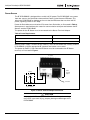
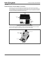
1
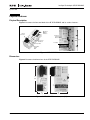
Intelligent Technologies
DeviceNet Starter Network Adapter Product
(D77B-DSNAP)
Installation and User Manual
Publication No. MN05004001E
September 2002
Supersedes February 2002
Intelligent Technologies (IT.) D77B-DSNAP
September 2002
Important Notice – Please Read
The product discussed in this literature is subject to terms and conditions outlined in
appropriate Eaton’s Cutler-Hammer selling policies. The sole source governing the
rights and remedies of any purchaser of this equipment is the relevant Eaton’s
Cutler-Hammer selling policy.
NO WARRANTIES, EXPRESS OR IMPLIED, INCLUDING WARRANTIES OF FITNESS
FOR A PARTICULAR PURPOSE OR MERCHANTABILITY, OR WARRANTIES ARISING
FROM COURSE OF DEALING OR USAGE OF TRADE, ARE MADE REGARDING THE
INFORMATION, RECOMMENDATIONS AND DESCRIPTIONS CONTAINED HEREIN. In
no event will Eaton’s Cutler-Hammer be responsible to the purchaser or user in
contract, in tort (including negligence), strict liability or otherwise for any special,
indirect, incidental or consequential damage or loss whatsoever, including but not
limited to damage or loss of use of equipment, plant or power system, cost of
capital, loss of power, additional expenses in the use of existing power facilities, or
claims against the purchaser or user by its customers resulting from the use of the
information, recommendations and descriptions contained herein.
Cover Photo: IT. D77B-DSNAP
Pub. No. MN05004001E
i
Intelligent Technologies (IT.) D77B-DSNAP
September 2002
Table of Contents
PRODUCT OVERVIEW
Description . . . . . . . . . . . . . . . . . . . . . . . . . . . . . . . . . . . . . . . . . . . . . . . . . . . . . . . . .
Features and Benefits . . . . . . . . . . . . . . . . . . . . . . . . . . . . . . . . . . . . . . . . . . . . . . . .
Safety . . . . . . . . . . . . . . . . . . . . . . . . . . . . . . . . . . . . . . . . . . . . . . . . . . . . . . . . . . . . .
Environmental Ratings . . . . . . . . . . . . . . . . . . . . . . . . . . . . . . . . . . . . . . . . . . . . . . .
Approvals/Certifications . . . . . . . . . . . . . . . . . . . . . . . . . . . . . . . . . . . . . . . . . . . . . .
Catalog Numbering System . . . . . . . . . . . . . . . . . . . . . . . . . . . . . . . . . . . . . . . . . . .
PHYSICAL FEATURES
Physical Description. . . . . . . . . . . . . . . . . . . . . . . . . . . . . . . . . . . . . . . . . . . . . . . . . .
Dimensions . . . . . . . . . . . . . . . . . . . . . . . . . . . . . . . . . . . . . . . . . . . . . . . . . . . . . . . . .
Power Source . . . . . . . . . . . . . . . . . . . . . . . . . . . . . . . . . . . . . . . . . . . . . . . . . . . . . . .
INSTALLATION
Mount the D77B-DSNAP to the Starter . . . . . . . . . . . . . . . . . . . . . . . . . . . . . . . . . .
Connect the Starter Terminal Adapter to the Starter . . . . . . . . . . . . . . . . . . . . . . .
Connect the D77B-DSNAP to DeviceNet . . . . . . . . . . . . . . . . . . . . . . . . . . . . . . . . .
Set the DeviceNet MAC ID and Baud Rate . . . . . . . . . . . . . . . . . . . . . . . . . . . . . . . .
OPERATION
“Out of Box” Operation . . . . . . . . . . . . . . . . . . . . . . . . . . . . . . . . . . . . . . . . . . . . . . .
Quick Start . . . . . . . . . . . . . . . . . . . . . . . . . . . . . . . . . . . . . . . . . . . . . . . . . . . . . . . . .
FVNR Motor Controller . . . . . . . . . . . . . . . . . . . . . . . . . . . . . . . . . . . . . . . . . . .
FVR Motor Controller . . . . . . . . . . . . . . . . . . . . . . . . . . . . . . . . . . . . . . . . . . . .
S751 Motor Controller. . . . . . . . . . . . . . . . . . . . . . . . . . . . . . . . . . . . . . . . . . . .
Safe State Behavior . . . . . . . . . . . . . . . . . . . . . . . . . . . . . . . . . . . . . . . . . . . . . . . . . .
Input and Output Assemblies . . . . . . . . . . . . . . . . . . . . . . . . . . . . . . . . . . . . . . . . . .
Input Assemby Data Definition. . . . . . . . . . . . . . . . . . . . . . . . . . . . . . . . . . . . .
Output Assembly Data Definition. . . . . . . . . . . . . . . . . . . . . . . . . . . . . . . . . . .
Typical Application. . . . . . . . . . . . . . . . . . . . . . . . . . . . . . . . . . . . . . . . . . . . . . . . . . .
Features. . . . . . . . . . . . . . . . . . . . . . . . . . . . . . . . . . . . . . . . . . . . . . . . . . . . . . . . . . . .
DeviceNet Status LED . . . . . . . . . . . . . . . . . . . . . . . . . . . . . . . . . . . . . . . . . . . . . . . .
Functional Description . . . . . . . . . . . . . . . . . . . . . . . . . . . . . . . . . . . . . . . . . . . . . . . .
CONFIGURATION
Using CH Studio . . . . . . . . . . . . . . . . . . . . . . . . . . . . . . . . . . . . . . . . . . . . . . . . . . . . .
General Properties. . . . . . . . . . . . . . . . . . . . . . . . . . . . . . . . . . . . . . . . . . . . . . .
Configuring Enhanced Features . . . . . . . . . . . . . . . . . . . . . . . . . . . . . . . . . . . .
Monitor the D77B-DSNAP. . . . . . . . . . . . . . . . . . . . . . . . . . . . . . . . . . . . . . . . .
Change the I/O Assemblies of the D77B-DSNAP . . . . . . . . . . . . . . . . . . . . . .
Using a Generic DeviceNet Tool . . . . . . . . . . . . . . . . . . . . . . . . . . . . . . . . . . . . . . . .
Autoconfiguring the D77B-DSNAP for the Starter . . . . . . . . . . . . . . . . . . . . . . . . .
TROUBLESHOOTING AND MAINTENANCE
Renewal Parts . . . . . . . . . . . . . . . . . . . . . . . . . . . . . . . . . . . . . . . . . . . . . . . . . . . . . . .
Troubleshooting . . . . . . . . . . . . . . . . . . . . . . . . . . . . . . . . . . . . . . . . . . . . . . . . . . . . .
APPENDIX A: SUPPORTED DEVICENET OBJECTS
DeviceNet Objects . . . . . . . . . . . . . . . . . . . . . . . . . . . . . . . . . . . . . . . . . . . . . . . . . . .
DeviceNet I/O Assemblies . . . . . . . . . . . . . . . . . . . . . . . . . . . . . . . . . . . . . . . . . . . . .
DeviceNet Input Assemblies. . . . . . . . . . . . . . . . . . . . . . . . . . . . . . . . . . . . . . .
DeviceNet Output Assemblies . . . . . . . . . . . . . . . . . . . . . . . . . . . . . . . . . . . . .
IT. PUBLICATIONS AND SUPPORT . . . . . . . . . . . . . . . . . . . . . . . . . . . . . . . . . . . . . . . . . .
ii
1
2
3
4
4
4
5
5
6
7
9
10
11
12
12
12
14
15
17
17
18
18
19
19
20
21
22
23
24
25
26
27
27
28
29
30
39
40
42
43
Pub. No. MN05004001E
Intelligent Technologies (IT.) D77B-DSNAP
September 2002
List of Figures
Figure 1: D77B-DSNAP Features . . . . . . . . . . . . . . . . . . . . . . . . . . . . . . . . . . . . . . .
Figure 2: D77B-DSNAP Dimensions, mm [in] . . . . . . . . . . . . . . . . . . . . . . . . . . . . .
Figure 3: Starter Terminal Adapter Connection . . . . . . . . . . . . . . . . . . . . . . . . . . .
Figure 4: D77B-DSNAP Alignment and Mounting . . . . . . . . . . . . . . . . . . . . . . . . .
Figure 5: D77B-DSNAP Removal . . . . . . . . . . . . . . . . . . . . . . . . . . . . . . . . . . . . . . .
Figure 6: Connecting Starter Terminal Adapter . . . . . . . . . . . . . . . . . . . . . . . . . . .
Figure 7: Jumper Installation . . . . . . . . . . . . . . . . . . . . . . . . . . . . . . . . . . . . . . . . . .
Figure 8: DIP Switch Setting Example . . . . . . . . . . . . . . . . . . . . . . . . . . . . . . . . . . .
Figure 9: D77B-DSNAP-X1 on FVNR IT. Starter . . . . . . . . . . . . . . . . . . . . . . . . . . .
Figure 10: D77B-DSNAP-X2 on FVR IT. Starter . . . . . . . . . . . . . . . . . . . . . . . . . . . .
Figure 11: D77B-DSNAP-X1 on S751 IT. Soft Starter . . . . . . . . . . . . . . . . . . . . . . .
Figure 12: Typical D77B-DSNAP Application . . . . . . . . . . . . . . . . . . . . . . . . . . . . .
5
5
6
8
8
9
9
11
13
14
16
19
Table 1: D77B-DSNAP Electromechanical Starter Connectivity Table. . . . . . . . . .
Table 2: D77B-DSNAP S751 Connectivity Table . . . . . . . . . . . . . . . . . . . . . . . . . . .
Table 3: Environmental Ratings . . . . . . . . . . . . . . . . . . . . . . . . . . . . . . . . . . . . . . . .
Table 4: Approvals/Certifications . . . . . . . . . . . . . . . . . . . . . . . . . . . . . . . . . . . . . . .
Table 5: Catalog Numbers. . . . . . . . . . . . . . . . . . . . . . . . . . . . . . . . . . . . . . . . . . . . .
Table 6: Power Requirements. . . . . . . . . . . . . . . . . . . . . . . . . . . . . . . . . . . . . . . . . .
Table 7: Starter Size/Available Auxiliary Locations on Mounted D77B-DSNAP. .
Table 8: DeviceNet Connection. . . . . . . . . . . . . . . . . . . . . . . . . . . . . . . . . . . . . . . . .
Table 9: Baud Rate Configuration Switches . . . . . . . . . . . . . . . . . . . . . . . . . . . . . .
Table 10: Input Assembly for Non-reversing Starter (E101, N101) . . . . . . . . . . . .
Table 11: Output Assembly for Non-reversing Starter (E101, N101)
and S751 Soft Start . . . . . . . . . . . . . . . . . . . . . . . . . . . . . . . . . . . . . . . . . .
Table 12: Input Assembly for Reversing Starter (E501, N501) . . . . . . . . . . . . . . . .
Table 13: Output Assembly for Reversing Starter (E501, N501) . . . . . . . . . . . . . .
Table 14: Input Assembly for S751 Soft Start . . . . . . . . . . . . . . . . . . . . . . . . . . . . .
Table 15: Output Assembly for S751 Soft Start . . . . . . . . . . . . . . . . . . . . . . . . . . .
Table 16: Allowable DeviceNet I/O Assemblies. . . . . . . . . . . . . . . . . . . . . . . . . . . .
Table 17: Input Assembly Data Definitions . . . . . . . . . . . . . . . . . . . . . . . . . . . . . . .
Table 18: Output Assembly Data Definitions. . . . . . . . . . . . . . . . . . . . . . . . . . . . . .
Table 19: Standard Protective Features . . . . . . . . . . . . . . . . . . . . . . . . . . . . . . . . . .
Table 20: Enhanced Features . . . . . . . . . . . . . . . . . . . . . . . . . . . . . . . . . . . . . . . . . .
Table 21: Combined MS/NS LED . . . . . . . . . . . . . . . . . . . . . . . . . . . . . . . . . . . . . . .
Table 22: Truth Table . . . . . . . . . . . . . . . . . . . . . . . . . . . . . . . . . . . . . . . . . . . . . . . . .
Table 23: D77B-DSNAP Renewal Parts . . . . . . . . . . . . . . . . . . . . . . . . . . . . . . . . . .
Table 24: Troubleshooting . . . . . . . . . . . . . . . . . . . . . . . . . . . . . . . . . . . . . . . . . . . .
Table 25: Supported Objects. . . . . . . . . . . . . . . . . . . . . . . . . . . . . . . . . . . . . . . . . . .
Table 26: DeviceNet Object Common Services. . . . . . . . . . . . . . . . . . . . . . . . . . . .
Table 27: Identity Object 0x01. . . . . . . . . . . . . . . . . . . . . . . . . . . . . . . . . . . . . . . . . .
Table 28: DeviceNet Object 0x03 — Instance 1 . . . . . . . . . . . . . . . . . . . . . . . . . . . .
Table 29: Connection Object 0x05 — Instance 1 (Explicit Connection) . . . . . . . . .
Table 30: Connection Object 0x05 — Instance 2 (I/O Message). . . . . . . . . . . . . . .
Table 31: Discrete Input Object 0x08 . . . . . . . . . . . . . . . . . . . . . . . . . . . . . . . . . . . .
Table 32: Motor Data Object 0x28 — Instance 1 . . . . . . . . . . . . . . . . . . . . . . . . . . .
Table 33: Control Supervisor Object 0x29 — Instance 1 . . . . . . . . . . . . . . . . . . . .
Table 34: Overload Object 0x2C — Instance 1. . . . . . . . . . . . . . . . . . . . . . . . . . . . .
Table 35: Soft Start Object 0x2D — Instance 1 . . . . . . . . . . . . . . . . . . . . . . . . . . . .
Table 36: Allowable DeviceNet I/O Assemblies. . . . . . . . . . . . . . . . . . . . . . . . . . . .
Table 37: Reading Current Input Assembly . . . . . . . . . . . . . . . . . . . . . . . . . . . . . . .
Table 38: Setting Input Assembly. . . . . . . . . . . . . . . . . . . . . . . . . . . . . . . . . . . . . . .
Table 39: Reading Current Output Assembly . . . . . . . . . . . . . . . . . . . . . . . . . . . . .
1
1
4
4
4
6
7
10
11
13
List of Tables
Pub. No. MN05004001E
14
15
15
16
17
17
18
18
19
20
20
21
28
29
30
30
31
31
32
32
33
34
35
37
38
39
39
39
39
iii
Intelligent Technologies (IT.) D77B-DSNAP
September 2002
Table 40: Setting Output Assembly . . . . . . . . . . . . . . . . . . . . . . . . . . . . . . . . . . . . .
Table 41: Assembly 52 (0x34) — Basic Motor Starter . . . . . . . . . . . . . . . . . . . . . . .
Table 42: Assembly 53 (0x35) — Extended Motor Starter 1 . . . . . . . . . . . . . . . . . .
Table 43: Assembly 54 (0x36) — Extended Motor Starter 2 . . . . . . . . . . . . . . . . . .
Table 44: Assembly 60 (0x3C) — Basic Soft Start Input . . . . . . . . . . . . . . . . . . . . .
Table 45: Assembly 102 (0x66) — D77B-DSNAP Motor Starter . . . . . . . . . . . . . . .
Table 46: Assembly 103 (0x67) — D77B-DSNAP Extended Motor Starter. . . . . . .
Table 47: Assembly 105 (0x69) — D77B-DSNAP Abbreviated Motor Starter 1. . .
Table 48: Assembly 106 (0x6A) — D77B-DSNAP Abbreviated Motor Starter 2 . .
Table 49: Assembly 108 (0x6C) — D77B-DSNAP Motor Starter with Fault Code .
Table 50: Assembly 109 (0x6D) — D77B-DSNAP Expanded Motor Starter
with Fault Code . . . . . . . . . . . . . . . . . . . . . . . . . . . . . . . . . . . . . . . . . . . . .
Table 51: Assembly 114 (0x72) — Complete Status Assembly . . . . . . . . . . . . . . .
Table 52: Input Definitions . . . . . . . . . . . . . . . . . . . . . . . . . . . . . . . . . . . . . . . . . . . . .
Table 53: Assembly 3 (0x03) — Basic Motor Starter . . . . . . . . . . . . . . . . . . . . . . . .
Table 54: Assembly 5 (0x05) — Extended Motor Starter . . . . . . . . . . . . . . . . . . . .
Table 55: Output Definitions . . . . . . . . . . . . . . . . . . . . . . . . . . . . . . . . . . . . . . . . . . .
Table 56: IT. Publications . . . . . . . . . . . . . . . . . . . . . . . . . . . . . . . . . . . . . . . . . . . . . .
iv
39
40
40
40
40
40
40
41
41
41
41
41
42
42
42
42
43
Pub. No. MN05004001E
Intelligent Technologies (IT.) D77B-DSNAP
September 2002
Product Overview
Description
Cutler-Hammer Intelligent Technologies (IT.) D77B-DSNAP (DeviceNet Starter Network
Adapter Product) by Eaton Corporation is the result of a substantive engineering and
marketing effort, involving extensive customer input. This product has greatly increased
functionality of the IT. Electromechanical Starter with the addition of enhanced features. This
front-mount device is a single DeviceNet node providing control and monitoring of an IT.
Electromechanical Starter application.
The D77B-DSNAP provides a communication interface to the following IT. Electromechanical
Starters.
Table 1: D77B-DSNAP Electromechanical Starter Connectivity Table
IEC
E101, FVNR
E501, FVR
NEMA
N101, FVNR
N501, FVR
B
00
Frame
Width
45 mm
0
C
1
54 mm
D
2
76 mm
E
3
105 mm
4
F
5
140 mm
Table 2: D77B-DSNAP S751 Connectivity Table
S751 Soft Start
All
This manual specifically addresses the DeviceNet Starter Network Adapter Product
(D77B-DSNAP). The D77B-DSNAP provides connectivity to DeviceNet supporting Group 2
slave, I/O poll and explicit messaging.
For further information on the IT. family of devices, visit our Web site at:
www.cutler-hammer.eaton.com/it
Notice
The D77B-DSNAP can only be applied with the IT. family of starters.
Pub. No. MN05004001E
1
Intelligent Technologies (IT.) D77B-DSNAP
September 2002
Features and Benefits
The IT. D77B-DSNAP includes the following significant features:
2
●
Communication to DeviceNet consuming one DeviceNet MAC ID
●
Control of non-reversing and reversing IT. Starters and S751 Soft Start
●
Monitoring of non-reversing and reversing IT. Starters and S751 Soft Start
●
Easy direct mounting to the front of IT. Starters and S751 Soft Start
●
Optional ground fault detector
●
No special software application required for normal setup. MAC ID and baud rate are
set with DIP switches
●
Warning levels that are user-settable
Pub. No. MN05004001E
Intelligent Technologies (IT.) D77B-DSNAP
September 2002
Safety
The following safety statements relate to the installation, setup and operation of the Eaton’s
Cutler-Hammer IT. D77B-DSNAP and Starter.
Notice
Make sure you read and understand the installation procedures in
this manual before you attempt to set up or operate the equipment.
WARNING
This instruction manual should be used for proper installation,
setup and operation of the IT. D77B-DSNAP. Improperly installing
and maintaining this product can result in serious personal injury
or property damage. Before attempting installation, setup or
operation, read and understand this entire manual.
WARNING
Hazardous voltage can cause electric shock and burns. Always
disconnect power before proceeding with any work on this product.
WARNING
Only apply 24V DC to the Terminal Adapter power terminals. Use
of any other voltage may result in personal injury, property damage
and damage to the IT. D77B-DSNAP.
WARNING
To provide continued protection against fire or shock hazard, the
complete IT. D77B-DSNAP must be replaced if it becomes
inoperative.
Environmental Ratings
The following environmental ratings apply to the D77B-DSNAP.
Table 3: Environmental Ratings
Category
Description
Specification
Transportation/
Storage
Temperature
-50°C to 80°C [-58°F to 176°F]
Humidity
5 – 95% non-condensing
Temperature
0°C to 60°C [32°F to 140°F]
Operating
Pub. No. MN05004001E
Humidity
5 – 95% non-condensing
Altitude
Above 2000 meters [6600 feet] consult factory
Shock (IEC 68-2-27)
15G in any direction for 11 milliseconds
Vibration (IEC 68-2-6)
5 – 150 Hz, 5G, 0.7 mm maximum peak-to-peak
3
Intelligent Technologies (IT.) D77B-DSNAP
September 2002
Approvals/Certifications
The following approvals and certifications apply to the D77B-DSNAP.
Table 4: Approvals/Certifications
Standard
Approval/Certification
Agency Certifications
UL 508
CE (Low Voltage Directive)
CSA C22.2 No. 14
ODVA Group 2 slave no UCMM
Radiated and Conducted Emissions
EN 5011 Class A
Electrical/EMC
ESD Immunity (IEC 61000-4-2)
68 kV air, 64 kV contact
Radiated Immunity (IEC 61000-4-3)
10 V/m 80 – 1000 MHz, 80% amplitude modulation @ 1 kHz
Fast Transient (IEC 61000-4-4)
62 kV supply and control
61 kV communications
Surge (IEC 61000-4-5)
61 kV line-to-line
62 kV line-to-ground
RF Conducted (IEC 61000-4-6)
10V, 0.15 – 80 MHz
Magnetic Field (IEC 61000-4-8)
30 A/m, 50 Hz
Voltage Dips (IEC 61000-4-11)
30% dip @ 10 ms
60% dip @ 100 ms
>95% interrupt @ 5 ms
Protection Degree (IEC 60947-1)
IP20
Catalog Numbering System
The D77B-DSNAP can be ordered as an assembly or as individual components. The
assembly includes all components for normal operation.
Table 5: Catalog Numbers
4
Description
Catalog Number
SNAP Jumper to terminal adapter
D77B-RJJ1
D77B-DSNAP Assembly of terminal adapter, jumper and D77B-DSNAP
D77B-DSNAP-X1
D77B-DSNAP Assembly of terminal adapter, jumper, D77B-DSNAP and second
contactor sensor
D77B-DSNAP-X2
DeviceNet Start Network Adapter Product
D77B-DSNAP
SNAP Terminal Adapter for FVR and FVNR starters and S751 Soft Start
D77B-TC8
Second contactor sensor for FVR starters and contactors
D77B-A2
Ground Fault Detector for 45 mm and 54 mm frame starters
D77B-GF1
Ground Fault Detector for 76 mm and 105 mm starters
D77B-GF2
Ground Fault Detector for 140 mm starters
D77B-GF3
Pub. No. MN05004001E
Intelligent Technologies (IT.) D77B-DSNAP
September 2002
Physical Features
Physical Description
Figure 1 illustrates the front and back of the IT. D77B-DSNAP and its various features.
Baud and
MAC ID
Switches
Starter
Connector
Contactor
Position
Detector
Feet
Connector
Breakout
Lock Tab
Push Tab
DeviceNet
Status
LED
Figure 1: D77B-DSNAP Features
Dimensions
Figure 2 illustrates the dimensions of the IT. D77B-DSNAP.
Side
Front
62
[2.4]
26
[1.0]
49
[1.9]
Figure 2: D77B-DSNAP Dimensions, mm [in]
Pub. No. MN05004001E
5
Intelligent Technologies (IT.) D77B-DSNAP
September 2002
Power Source
The IT. D77B-DSNAP is designed for use with 24V DC power. The D77B-DSNAP uses power
from two sources, the DeviceNet subnet and the Eaton’s Cutler-Hammer IT. Starter. This
allows the D77B-DSNAP to indicate to the user that the IT. Starter does not have 24V DC
power, signaling a fault or an E-Stop.
Power for DeviceNet communication CPU comes from DeviceNet, as illustrated in Table 6.
Some power is required from the starter for communication to be present between the IT.
Starters and the D77B-DSNAP.
The power for the IT. Starter must be connected to the Starter Terminal Adapter.
Table 6: Power Requirements
Current Source
Load
DeviceNet
90 mA
IT. Starter
Less than 1 mA
When a power supply is chosen for the starter(s), size it for the load of the starter(s) and the
D77B-DSNAP using the appropriate IT. contactor and starter user manual.
The power for Eaton’s Cutler-Hammer IT. Starter must be connected to the IT. Starter
terminal, as illustrated in Figure 3.
To Starter
–
SNAP
Terminal
Adapter
24V DC
+
Optional
J1
To DSNAP
E-Stop
(Push to Open)
Figure 3: Starter Terminal Adapter Connection
CAUTION
Only apply 24V DC to the D77B-DSNAP. Use of any other voltage
may result in personal injury, property damage and damage to the
D77B-DSNAP.
6
Pub. No. MN05004001E
Intelligent Technologies (IT.) D77B-DSNAP
September 2002
Installation
Mount the D77B-DSNAP to the Starter
The IT. D77B-DSNAP is designed to be installed in the auxiliary contact locations of the IT.
family of starters. On all starters, one or more auxiliaries can be used along with the D77BDSNAP. The following table lists starters and indicates the number of available auxiliary
locations for each.
Table 7: Starter Size/Available Auxiliary Locations on Mounted D77B-DSNAP
Pub. No. MN05004001E
Starter Frame Size (mm)
Number of Available Auxiliary Locations with
Center Mounted D77B-DSNAP
45
1 single Auxiliary
54
1 single or 1 dual Auxiliary
76
2 single or 2 dual Auxiliary
105
2 single or 2 dual Auxiliary
140
2 single or 2 dual Auxiliary
7
Intelligent Technologies (IT.) D77B-DSNAP
September 2002
Use the following steps and illustration in Figure 4 to mount the D77B-DSNAP:
1. Align and insert both the D77B-DSNAP feet into the auxiliary starter contact mounting
slots on the starter, as illustrated in Figure 4.
Recommendation: Use the middle auxiliary contact mounting slot on the starter contact
block when mounting the D77B-DSNAP.
2. Slide the D77B-DSNAP down until a “click” is heard. This ensures that the D77B-DSNAP
is mounted securely to the starter.
1. Align
and
Insert
2. Slide
Feet
Figure 4: D77B-DSNAP Alignment and Mounting
Use the following steps and illustration in Figure 5 to remove the D77B-DSNAP:
1. Press the push tab protruding from the D77B-DSNAP front, Figure 1 on Page 5.
2. Slide the D77B-DSNAP up.
3. Pull the D77B-DSNAP away from the starter contact block.
3. Pull
Away
2. Slide
1. Push Tab
Figure 5: D77B-DSNAP Removal
8
Pub. No. MN05004001E
Intelligent Technologies (IT.) D77B-DSNAP
September 2002
Connect the Starter Terminal Adapter to the Starter
Loosen the screws on the removable terminal block of the starter and insert the Starter
Terminal Adapter into the removable terminal block. Tighten the screws on the terminal block
(4.5 in-lb or 0.5 Nm) securing the Starter Terminal Adapter into the removable terminal block.
Install the removable terminal block into the starter.
To Starter
Terminal
Block
Starter
Terminal
Adapter
Figure 6: Connecting Starter Terminal Adapter
Insert one end of the Starter Adapter Jumper (Catalog Number D77B-RJJ1) into J1 on the
Starter Terminal Adapter and the other end into or on the D77B-DSNAP.
D77B-DSNAP
D77B-RJJ1
(Jumper)
D77B-TC8
Figure 7: Jumper Installation
Pub. No. MN05004001E
9
Intelligent Technologies (IT.) D77B-DSNAP
September 2002
Connect the D77B-DSNAP to DeviceNet
Connect the DeviceNet cable to the 5-position DeviceNet Connector located at the top of the
D77B-DSNAP.
●
The 5-position DeviceNet Connector has screws for positive retention that need to be
loosened to remove the terminal block.
●
The D77B-DSNAP will work with thick and thin media.
●
The DeviceNet cable is color-coded and matches the colors on the DeviceNet
connector.
●
Use only one wire per terminal.
●
Tighten the screws to 0.5 Nm (4.5 lb-in).
For further information on DeviceNet wiring practices and power considerations, refer to the
DeviceNet Installation Planning Guide, Publication Number SA-370.
Table 8: DeviceNet Connection
10
Connector Legend
DeviceNet Wire
Signal
V+
Red
+24V DC
CH
White
CAN High
D
Shield
Shield
CL
Blue
CAN Low
V-
Black
Signal Common
Pub. No. MN05004001E
Intelligent Technologies (IT.) D77B-DSNAP
September 2002
Set the DeviceNet MAC ID and Baud Rate
The MAC ID and baud can only be set using the DIP switches on the front of the D77B-DSNAP.
A software tool (such as CH Studio) can view the settings for the D77B-DSNAP MAC ID and
baud rate, but cannot be used to modify them.
Refer to the following instructions, figure and table when setting the MAC ID and baud rate.
●
Moving a DIP switch to the right is ON and moving the switch to the left is OFF. The
MAC ID is in binary with the major units numbered to the right of the switch on the side
label. Adding up the major units set to ON determines the MAC ID of the D77B-DSNAP.
Example: To set the MAC ID to 25, start from the top (or 32) and set the switches to OFF, ON,
ON, OFF, OFF, ON (16+8+1=25).
●
The baud rate is set using the configuration switches B0 and B1.
Most significant bit to be at top or left end of switch block.
To set the DeviceNet MAC ID and baud rate, set the DIP switches
to the desired settings.
The following example is set to MAC ID=25 and Baud 125K.
OFF
ON
B1
Baud
B0
32
16
8
MAC ID
4
2
1
Figure 8: DIP Switch Setting Example
Table 9: Baud Rate Configuration Switches
Pub. No. MN05004001E
B1
B0
Baud
OFF
OFF
125K
OFF
ON
250K
ON
OFF
500K
ON
ON
Not Allowed
11
Intelligent Technologies (IT.) D77B-DSNAP
September 2002
Operation
This section provides details about the following features and functions of D77B-DSNAP
operation:
●
“Out of box” operation
●
Quick Start
●
Typical application
●
Enhanced features
●
DeviceNet input/output assemblies
●
DeviceNet Status LED
●
Functional Description
“Out of Box” Operation
Note: Before applying power to the D77B-DSNAP for the first time, make sure it is properly
mounted on the starter and that all connections are made (DeviceNet, terminal adapter
and auxiliary connector).
When the D77B-DSNAP is properly installed, and has a properly set baud and MAC ID, per the
“Installation” section on Page 11, the following tables in the Quick Start section indicate the
information to expect for I/O assemblies on DeviceNet.
Quick Start
This part of the section provides the information necessary to install and operate the D77BDSNAP on a Full Voltage Non-reversing (FVNR) IT. Starter, Full Voltage Reversing (FVR) IT.
Starter and an S751 Soft Start motor controller. Detailed information is available in Appendix A
for setup of enhanced parameters and extended Input and Output data (assemblies).
FVNR Motor Controller
First, follow the instructions on how to mount the D77B-DSNAP as outlined in Mount the
D77B-DNSAP to the Starter on Page 7.
Second, follow the instruction on how to connect the Starter Terminal Adapter to the starter as
outlined in Connect the Starter Terminal Adapter to the Starter on Page 9.
12
Pub. No. MN05004001E
Intelligent Technologies (IT.) D77B-DSNAP
September 2002
Jumper
Terminal
Adapter
Figure 9: D77B-DSNAP-X1 on FVNR IT. Starter
Third, follow the instructions on how to set the MAC ID and Baud Rate as outlined in Set the
DeviceNet MAC ID and Baud Rate on Page 11.
Fourth, follow the instructions on how to wire the D77B-DSNAP to DeviceNet as outlined in
Connect the D77B-DSNAP to DeviceNet on Page 10.
The D77B-DSNAP will auto configure to the FVNR IT. Starter when the D77B-DSNAP and the IT.
Starter are first powered (together). After the auto configuration is complete, the D77B-DSNAP
is “married” to that specific size, type and overload range of IT. Starter. Any attempt to install
an already “married” D77B-DSNAP onto another IT. Starter without first performing a reset
(Appendix A, Page 30) will result in the D77B-DSNAP entering a recoverable fault state
(flashing red MS/NS LED); the D77B-DSNAP will not operate the IT. Starter.
Default Input Assembly
The out of box input assembly (data mapped to the input registers within the system
controller) is the following:
Table 10: Input Assembly for Non-reversing Starter (E101, N101)
Assembly 105 (0x69) – Input (Producing) – D77B-DSNAP Abbreviated Motor Starter 1
Pub. No. MN05004001E
Byte
Bit 7
Bit 6
0
At
Reserved
Reference
Bit 5
Bit 4
Bit 3
Bit 2
CtrlFrom
Net
Ready
Reserved Running1 Warning
1
% Thermal Capacity
2
% FLA
3
Fault Code (Low byte only)
Bit 1
Bit 0
Fault
13
Intelligent Technologies (IT.) D77B-DSNAP
September 2002
Default Output Assembly
The out of box output assembly (data mapped to the output registers within the system
controller) is the following:
Table 11: Output Assembly for Non-reversing Starter (E101, N101) and S751 Soft Start
Instance 3: Basic Motor Starter
Byte
Bit 7
Bit 6
Bit 5
Bit 4
Bit 3
Bit 2
Bit 1
Bit 0
0
Reserved
Reserved
Reserved
Reserved
Reserved
FaultReset Reserved
Run1
FVR Motor Controller
First, follow the instructions on how to mount the D77B-DSNAP as outlined in Mount the
D77B-DNSAP to the Starter on Page 7.
Note: The 45 mm and 54 mm frame IT. Starters will require the user to depress the cross over
cover locking tab while installing the D77B-DNSAP. Simply depress the tab while
inserting the D77B-DSNAP feet into the slot on the IT. Starter to ease installation.
Second, follow the instruction on how to connect the Starter Terminal Adapter to the starter as
outlined in Connect the Starter Terminal Adapter to the Starter on Page 9.
Third, the secondary contactor sensor (D77B-A2) needs to be installed. Install the secondary
contactor sensor on the second contactor just as you would install an auxiliary (align the feet
and slide towards the bottom). Using a screwdriver, pry up the connector access breakout
(Figure 1, Page 5) and remove the breakout. Insert the green connector that is connected via a
wire to the second contactor sensor into the breakout making sure to take notice of the
alignment tabs for proper orientation.
Cover Locking Tab
D77B-A2 Second
Contactor Sensor
Connector Breakout
Alignment Tab
Jumper
Terminal Adapter
Figure 10: D77B-DSNAP-X2 on FVR IT. Starter
14
Pub. No. MN05004001E
Intelligent Technologies (IT.) D77B-DSNAP
September 2002
Fourth, follow the instructions on how to set the MAC ID and Baud Rate as outlined in Set the
DeviceNet MAC ID and Baud Rate on Page 11.
Fifth, follow the instructions on how to wire the D77B-DSNAP to DeviceNet as outlined in
Connect the D77B-DSNAP to DeviceNet on Page 10.
The D77B-DSNAP will auto configure to the FVR IT. Starter when the D77B-DSNAP and the IT.
Starter are first powered (together). It is important that the second contactor sensor is installed
on the second contactor and that the green connector is installed into the breakout. If this is not
performed, the auto configuration will set the D77B-DSNAP up for an FRNR IT. Starter. After the
auto configuration is complete, the D77B-DSNAP is “married” to that specific size, type and
overload range of IT. Starter. Any attempt to install an already “married” D77B-DSNAP onto
another IT. Starter without first performing a reset (Appendix A, Page 30) will result in the
D77B-DSNAP entering a recoverable fault state (flashing red MS/NS LED); the D77B-DSNAP
will not operate the IT. Starter.
Default Input Assembly
The out of box input assembly (data mapped to the input registers within the system
controller) is the following:
Table 12: Input Assembly for Reversing Starter (E501, N501)
Assembly 106 (0x6A) – Input (Producing) – D77B-DSNAP Abbreviated Motor Starter 2
Byte
Bit 7
Bit 6
0
At
Reserved
Reference
Bit 5
Bit 4
Bit 3
Bit 2
CtrlFrom
Net
Ready
Running2 Running1 Warning
1
% Thermal Capacity
2
% FLA
3
Fault Code (Low byte only)
Bit 1
Bit 0
Fault
Default Output Assembly
The out of box output assembly (data mapped to the output registers within the system
controller) is the following:
Table 13: Output Assembly for Reversing Starter (E501, N501)
Instance 5: Extended Motor Starter
Byte
Bit 7
Bit 6
Bit 5
Bit 4
Bit 3
Bit 2
Bit 1
0
Reserved
Reserved
Reserved
Reserved
Reserved
FaultReset Run2
Bit 0
Run1
S751 Motor Controller
First, follow the instructions on how to mount the D77B-DSNAP as outlined in Mount the
D77B-DNSAP to the Starter on Page 7 (mounts in the same position as an FVNR starter).
Second, follow the instruction on how to connect the Starter Terminal Adapter to the starter as
outlined in Connect the Starter Terminal Adapter to the Starter on Page 9.
Pub. No. MN05004001E
15
Intelligent Technologies (IT.) D77B-DSNAP
September 2002
Jumper
Terminal
Adapter
Figure 11: D77B-DSNAP-X1 on S751 IT. Soft Starter
Third, follow the instructions on how to set the MAC ID and Baud Rate as outlined in Set the
DeviceNet MAC ID and Baud Rate on Page 11.
Fourth, follow the instructions on how to wire the D77B-DSNAP to DeviceNet as outlined in
Connect the D77B-DSNAP to DeviceNet on Page 10.
The D77B-DSNAP will auto configure to the S751 Starter when the D77B-DSNAP and the IT.
Starter are first powered (together). After the auto configuration is complete, the D77B-DSNAP
is “married” to that specific size, and overload range of S751. Any attempt to install an already
“married” D77B-DSNAP onto another S751 without first performing a reset (Appendix, Page
30) will result in the D77B-DSNAP entering a recoverable fault state (flashing red MS/NS LED);
the D77B-DSNAP will not operate the IT. Starter.
Default Input Assembly
The out of box input assembly (data mapped to the input registers within the system
controller) is the following:
Table 14: Input Assembly for S751 Soft Start
Assembly 105 (0x69) – Input (Producing) – D77B-DSNAP Abbreviated Motor Starter 1
16
Byte
Bit 7
Bit 6
0
At
Reserved
Reference
Bit 5
Bit 4
Bit 3
Bit 2
CtrlFrom
Net
Ready
Reserved Running1 Warning
1
% Thermal Capacity
2
% FLA
3
Fault Code (Low byte only)
Bit 1
Bit 0
Fault
Pub. No. MN05004001E
Intelligent Technologies (IT.) D77B-DSNAP
September 2002
Default Output Assembly
The out of box output assembly (data mapped to the output registers within the system
controller) is the following:
Table 15: Output Assembly for S751 Soft Start
Instance 5: Extended Motor Starter
Byte
Bit 7
Bit 6
Bit 5
Bit 4
Bit 3
Bit 2
Bit 1
0
Reserved
Reserved
Reserved
Reserved
Reserved
FaultReset Run2
Bit 0
Run1
Safe State Behavior
The safe state behavior of the D77B-DSNAP is factory set to Fault and Stop. Refer to Page 35,
Table 33 Control Supervisor Object (0x29) Instance 0x01 (16 Dec.) for more information. Safe
State is defined as the state in which the D77B-DSNAP will place the motor controller when a
communication loss is detected. The D77B-DSNAP will be in a safe state when the unit is
powered but does not have a valid I/O connection established.
WARNING
If the Safe State value is set to Run1 or Run2, any time the D77BDSNAP is powered and does not have a valid I/O connection, the
motor controller will be commanded to the Safe State value. This
includes first powering up the DeviceNet system (D77B-DSNAP)
and not having the controller on-line.
Input and Output Assemblies
An I/O assembly is an ordered collection of data that the system controller exchanges with
the D77B-DSNAP for monitoring and control. The input assembly is the data that is sent from
the D77B-DSNAP to the system controller for monitoring of the D77B-DSNAP. The output
assembly is the data that is sent from the system controller to the D77B-DSNAP for control of
the D77B-DSNAP.
The D77B-DSNAP offers a variety of input and output assemblies, as indicated in the following
table. The tables in this part of the section provide data definitions and details on these
assemblies.
Table 16: Allowable DeviceNet I/O Assemblies
Motor Controller
Allowable Input
Assemblies
Allowable Output
Assemblies
Non-reversing (E101, N101)
52, 53, 102, 105*, 108, 114
3*
Reversing (E501, N501)
52, 53, 54, 102, 103, 105, 106*, 108, 109, 114
5*
Soft Start (S751)
52, 53, 60, 102, 105*, 108, 114
3*
* Indicates the default
Use a DeviceNet configuration tool to select the assemblies of the D77B-DSNAP. The CH
Studio configuration tool provides the means to configure the assemblies quickly and easily,
as described in the “Configuration” section of this manual. When using a generic DeviceNet
tool, use the tables within this section to set up the assemblies. An EDS is available on Eaton’s
Cutler-Hammer Web site (www.cutler-hammer.eaton.com/it).
Refer to Appendix A on Page 39 for all input and output assembly information.
Pub. No. MN05004001E
17
Intelligent Technologies (IT.) D77B-DSNAP
September 2002
Input Assembly Data Definition
Use the following tables when setting up the D77B-DSNAP input assemblies.
Table 17: Input Assembly Data Definitions
Data
Description
Fault/Trip
The motor controller is faulted or tripped
Note: A “Faulted” M.C. may still respond to a Run1 or Run2 command
Warning
The motor controller has a warning of an impending trip
Running 1
Primary contactor is being commanded to run
Running 2
Secondary contactor is being commanded to run
Ready
The motor controller is configured and communicating with starter
CtrlFrom Net
The motor controller is controlled from DeviceNet
At Reference
This states that the motor controller is in the state that it is commanded to be
in, or that the S751 is in bypass. For FVR applications, a D77B-AC2 is required
for this bit to be active while in reverse.
% Thermal Capacity
% thermal capacity of the motor from 0 to 100%
Average Current
Average RMS current of the motor
% FLA
The ratio of the running current divided by the FLA setting on the overload
Fault Codes and
Warning Codes
Code for the fault of the motor controller.
Valid fault and warning codes are:
0 = No Fault
10 = Test
20 = Current Trip
21 = Thermal Overload
22 = Phase Loss
26 = Phase Imbalance
27 = Ground Fault
41 = Control Undervoltage
62 = Memory Fault
63 = Hardware Link Fault (Not Communicating with Starter)
64 = No Device Power
71 = Fail to Close Primary Contactor
72 = Fail to Open Primary Contactor
101 = Invalid Attached Device Version
102 = SCR Over Temperature
103 = Watchdog
104 = SNAP Protocol Failure to Connect
105 = SNAP Protocol Fault
106 = Temperature Sensor Fault
171 = Fail to Close Second Contactor
172 = Fail to Open Second Contactor
173 = Invalid Action Attempted
Output Assembly Data Definition
Use the following table when setting up the D77B-DSNAP output assemblies.
Table 18: Output Assembly Data Definitions
18
Data
Description
Run 1
Energize the primary contactor/Soft Starter
Run 2
Energize the secondary contactor
Fault Reset
Reset the fault
Pub. No. MN05004001E
Intelligent Technologies (IT.) D77B-DSNAP
September 2002
Typical Application
The following figure illustrates a typical D77B-DSNAP application, where a single D77BDSNAP is connected to a single motor controller and where the motor controllers are
distributed throughout the DeviceNet subnet. The subnet is then being controlled by a PC or
PLC, which scans the D77B-DSNAP for control and monitoring information.
DeviceNet
System
Controller
Figure 12: Typical D77B-DSNAP Application
Note: Such an application typically has more devices on DeviceNet than are shown in this
illustration, such as drives, I/O and user interface units.
Features
Table 19: Standard Protective Features
Trip
Definition
Phase Current
A phase current unbalance trip will occur if one or two of the line currents are 40 –
Unbalance/Phase 60% or less of the remaining line(s) for longer than 10 seconds.
Loss
A phase loss trip will occur with a load current of at least 75% of the minimum FLA
if one of the two input line voltages is lost, with the line current going to zero for
longer than 10 seconds.
Thermal
Overload
While the motor is running and depending on the FLA and trip class settings, when
the FLA is exceeded for a period of time (depending on the trip class setting), a
thermal overload trip will occur. For more information on this feature, see the
Contactor and Starter User Manual (Publication No. 49400).
Note: The threshold values for Thermal Overload and Phase Current Unbalance can not be
modified.
Pub. No. MN05004001E
19
Intelligent Technologies (IT.) D77B-DSNAP
September 2002
Table 20: Enhanced Features
Fault
Definition
Ground Fault
With the addition of a Ground Fault module, the D77B-DSNAP will trip when the
module detects a ground fault. The level of the trip is adjusted on the Ground Fault
Module. The Ground Fault Module is connected to the D77B-DSNAP through the
Auxiliary opening on the front of the D77B-DSNAP.
Underload
Warning
While the motor is running, a warning will be activated when the current falls below
a user-settable % of overload’s FLA pot setting.
Current
Threshold Warning
While the motor is running, a warning will be activated when the current rises
above a user-settable % of overload’s FLA pot setting.
SCR Over
Temperature
To protect the SCRs from premature damage, a temperature sensor monitors the
SCR temperature. If the monitored temperature is too high, the S751 will trip on
SCR overtemperature.
Contactor
Dropout
The contactor dropped out when it was commanded to be energized.
DeviceNet Status LED
The combined module status/network status (MS/NS) LED is located on the lower right of the
D77B-DSNAP as pictured in Figure 1: D77B-DSNAP Features.
The following table describes the state of the MS/NS LED.
Table 21: Combined MS/NS LED
20
State
LED
Non-existent
OFF
Standby
Flashing Green
Operational
Not connected: Flashing Green
Operational
Connected: Green
Recoverable Fault
Flashing Red
Unrecoverable Fault
Red
Initializing
Red/Green Flash
Pub. No. MN05004001E
Intelligent Technologies (IT.) D77B-DSNAP
September 2002
Functional Description
Table 22: Truth Table
Fieldbus Inputs
Old State
Run 1 Run 2 Reset Event
New State
Action
FAULTED
–
–
1
RESET
OFF
FAULT = 0
OFF
0
0
–
NONE
OFF
NONE
OFF
1
0
–
RUN 1
RUNNING 1
RUNNING 1 = 1
OFF
0
1
–
RUN 2
RUNNING 2
RUNNING 2 = 1
OFF
1
1
–
RUN 1/RUN 2
OFF
NONE
RUNNING 1
1
1
–
RUN 2
RUNNING 1
NONE
RUNNING 2
1
1
–
RUN 1
RUNNING 2
NONE
RUNNING 1
1
0
–
FAULT
FAULTED
RUNNING 1 = 0
FAULT = 1
RUNNING 2
0
1
–
FAULT
FAULTED
RUNNING 2 = 0
FAULT = 1
RUNNING 1
1
0
–
WARNING
RUNNING 1
WARNING = 1
RUNNING 2
0
1
–
WARNING
RUNNING 2
WARNING = 1
– = state not important
1 = state true (energized)
0 = state false (de-energized)
WARNING = any warning in Table 17
Pub. No. MN05004001E
RUNNING 1 = Run/FWD/SLOW
RUNNING 2 = REV/FAST
FAULT = any fault in Table 17
21
Intelligent Technologies (IT.) D77B-DSNAP
September 2002
Configuration
The only configuration that is necessary for normal operation of the D77B-DSNAP is setting
the MAC ID and baud rate, as described in the “Installation” section, Page 11. However, the
D77B-DSNAP offers a variety of enhanced features. When these features are required, use
the CH Studio software suite or a generic DeviceNet tool to perform the configuration.
This section includes the following configuration procedures, and related instructions and
information:
●
Using CH Studio
– View D77B-DSNAP General Properties
– Configure Enhanced Features
– Monitor the D77B-DSNAP Status
– Change the I/O Assemblies
●
Using a generic DeviceNet tool
Using CH Studio
The CH Studio software application is designed for programming and configuring industrial
automation systems. The application simplifies the monitoring and configuration of entire
networks as well as the enhanced features of individual IT. communicating devices within
those networks.
CH Studio takes advantage of the Windows graphical interface to present a suite of tools that
is easy to learn and efficient to use, while meeting the requirements for developing complex
network configurations.
CH Studio performs the following configuration functions for DeviceNet networks:
22
●
Discover network devices
●
Display device properties
●
Monitor and configure network devices
●
Save existing network configurations
●
Configure networks off-line
●
Configure devices off-line
Pub. No. MN05004001E
Intelligent Technologies (IT.) D77B-DSNAP
September 2002
General Properties
The general properties of the D77B-DSNAP are located in the General Tab of the Property
Pages for the device. The general properties include the firmware version, serial number,
status and much more.
Pub. No. MN05004001E
23
Intelligent Technologies (IT.) D77B-DSNAP
September 2002
Configuring Enhanced Features
The enhanced features of the D77B-DSNAP are configured using the Property Window and
the Property Pages. A complete list of all the features and settable attributes are available in
the Property Window.
24
Pub. No. MN05004001E
Intelligent Technologies (IT.) D77B-DSNAP
September 2002
Monitor the D77B-DSNAP
The running values of the D77B-DSNAP (current, thermal capacity and 24V DC control
voltage) can be monitored from the Monitor Tab of the Property Pages. Switching to the
Status Tab, all operational status can be monitored.
Pub. No. MN05004001E
25
Intelligent Technologies (IT.) D77B-DSNAP
September 2002
Change the I/O Assemblies of the D77B-DSNAP
All of the I/O assemblies are viewable and settable from the I/O Info Tab of the Property
Pages. The assembly can be changed by simply selecting on the new assembly and pressing
Apply in the lower right of the page. After the new assembly is chosen, a representation of
the data format and structure for the new I/O assembly is created.
26
Pub. No. MN05004001E
Intelligent Technologies (IT.) D77B-DSNAP
September 2002
Using a Generic DeviceNet Tool
When configuring the D77B-DSNAP with a DeviceNet management tool other than CH
Studio, refer to the tables in Appendix A: Supported DeviceNet Objects for the definitions of
individual attributes. In addition, an Electronic Data Sheet (EDS) file is available at the Web
site www.cutler-hammer.eaton.com/it for use with tools that can use an EDS file.
Follow these steps to configure a D77B-DSNAP through a generic DeviceNet tool:
1. Search for EDS and download the D77B-DSNAP EDS file from the Cutler-Hammer Web
site:
www.cutler-hammer.eaton.com/it
Note: There are multiple EDS files for the D77B-DSNAP, depending on whether it is used with
an FVR, FVNR or S751 configuration.
2. Open/start the tool.
3. Load the EDS file into the tool.
4. Go on-line and connect to the D77B-DSNAP you wish to configure.
5. Open the EDS for the D77B-DSNAP and edit the attributes. For a full list of attributes and
definitions, see Appendix A: Supported DeviceNet Objects.
6. Send the changed attributes to the D77B-DSNAP.
7. Close the tool.
Autoconfiguring the D77B-DSNAP for the Starter
1. Verify the D77B-RJJ1 is installed between J1 on the D77B-DSNAP and J1 on the Starter
Terminal Adapter.
2. Connect the “out-of-box” D77B-DSNAP to a powered DeviceNet network.
3. Apply power to the starter terminal adapter, the MS/NS LED should change from
blinking red to blinking green.
4. If possible verify that the configuration has occurred by reading the device type from the
Identity Object (instance 1 attribute 2)
0x000C — Configuration has not occurred
0x0016 — Starter
0x0017 — S751 Soft Start
Note: It can take as long as 15 seconds for the autoconfiguration to be performed on an S751
and 7 seconds for an IT. Starter.
Note: The autoconfiguration is a one-time event. To autoconfigure the D77B-DSNAP for
another motor controller, an out-of-box reset must be performed. Using a DeviceNet
configuration tool, perform a reset to the Identity Object, instance 1 data = 1.
Pub. No. MN05004001E
27
Intelligent Technologies (IT.) D77B-DSNAP
September 2002
Troubleshooting and Maintenance
Renewal Parts
The following table lists the renewal parts for the IT. D77B-DSNAP.
Table 23: D77B-DSNAP Renewal Parts
28
Description
Catalog Number
SNAP Jumper to terminal adapter
D77B-RJJ1
D77B-DSNAP Assembly of terminal adapter, jumper and D77B-DSNAP
D77B-DSNAP-X1
D77B-DSNAP Assembly of terminal adapter, jumper, D77B-DSNAP and second
contactor sensor
D77B-DSNAP-X2
DeviceNet Start Network Adapter Product
D77B-DSNAP
SNAP Terminal Adapter for FVR and FVNR starters and S751 Soft Start
D77B-TC8
Second contactor sensor for FVR starters and contactors
D77B-A2
Ground Fault Detector for 45 mm and 54 mm frame starters
D77B-GF1
Ground Fault Detector for 76 mm and 105 mm starters
D77B-GF2
Ground Fault Detector for 140 mm starters
D77B-GF3
Pub. No. MN05004001E
Intelligent Technologies (IT.) D77B-DSNAP
September 2002
Troubleshooting
Table 24: Troubleshooting
Observation
Possible Cause
Corrective Action
MS/NS LED flashing red after
power-up
D77B-DSNAP is not
communicating to the IT. Starter
Check the D77B-RJJ1 jumper
between the D77B-DSNAP and
the D77B-TC8 terminal adapter.
Also check that the terminal
adapter is properly secured and
plugged into the IT. Starter.
The D77B-DSNAP was
configured or “married” to
another IT. Starter
Perform a reset (Appendix A
Page 30) to re-marry the
D77B-DSNAP to the IT. Starter.
The D77B-DSNAP is powered but Power the IT. Starter.
the IT. Starter is not
The MS/NS LED starts flashing
green and then turns to a
flashing red after power-up
D77B-DSNAP is not
communicating to the IT. Starter
Check the D77B-RJJ1 jumper
between the D77B-DSNAP and
the D77B-TC8 terminal adapter.
Also check that the terminal
adapter is properly secured and
plugged into the IT. Starter.
IT. Starter will not energize
IT. Starter is not powered
Verify that the IT. Starter has 24V
DC on the + and - of the terminal
block, the Power LED should be
green on the D77B-TC8 terminal
adapter.
IT. Starter may be tripped
Reset the trip.
Improper bit set in output
assembly
Check the output assembly data
position and verify with the
control logic.
Second Contactor will not
energize
During the “marriage” the wrong Verify that the product code
configuration was detected
(Table 27 instance 3) is 0x1102
(4354 dec.). If the product code is
not correct, verify that the second
contact sensor is installed and
wired, that the IT. Starter is
powered and perform a Reset
to Out of Box (Appendix A,
Page 30).
Improper bit set in output
assembly
Check the output assembly data
position and verify with the
control logic. Verify the correct
output assembly is being used.
Mechanical interlock is jammed
The primary contactor is already Only one contactor can be
energized
energized at a time.
A “failed to close” fault is
generated when the second
contactor is energized
Pub. No. MN05004001E
The wiring between the D77B-A2 Verify all connections on the
and the D77B-DSNAP is faulty.
D77B-A2 and the D77B-DSNAP.
Verify that the D77B-A2 is
properly connected to the second
contactor.
29
Intelligent Technologies (IT.) D77B-DSNAP
September 2002
Appendix A: Supported DeviceNet Objects
DeviceNet Objects
Table 25: Supported Objects
Object
Object ID
Page
Identity
0x01
Page 31
DeviceNet
0x03
Page 31
DeviceNet Connection
0x05
Page 32
Discrete Input Point
0x08
Page 33
Motor Data
0x28
Page 34
Motor Control Supervisor
0x29
Page 35
Overload
0x2C
Page 37
Soft Start
0x2D
Page 38
Supported DeviceNet I/O Assemblies
Page 39
Table 26: DeviceNet Object Common Services
Service Code
Service Name
0x0E
Get_Attribute_Single
0x10
Set_Attribute_Single
0x17
Nop
0x18
Get_Member
0x4B
Allocate_Master/Slave_Connection_Set
0x4C
Release_Master/Slave_Connection_Set
0x05
Reset
Reset to Out of Box
Service = Reset (0x05)
Class = Identity (0x01)
Instance = 0x01
Data = 01
30
Pub. No. MN05004001E
Intelligent Technologies (IT.) D77B-DSNAP
September 2002
Table 27: Identity Object 0x01
Attribute Access Data Type Name
Value
Instance 1
01
Get
UINT
Vendor Id
68 [0x44] = Cutler-Hammer
02
Get
UINT
Device Type
12 [0x0C] = Communication Adapter
22 [0x16] = Motor Starter
23 [0x17] = Soft Starter
03
Get
UINT
Product Code
4353 [0x1101] DSNAP, FVNR or S751
4354 [0x1102] DSNAP, FVR or two speed
04
Get
ARRAY
Revision
Byte 0 = Major Revision
Byte 1 = Minor Revision
06
Get
UDINT
Serial Number
Serial Number of D77B-DSNAP
09
Get
UINT
Configuration
CRC on configuration values
Consistency Value
176
Set
SHORT
STRING
User Label or
Tag Name
A user established ASCII string of 16 characters or
less
177
Get
USINT
Fault Value
Same as Atrribute 13 of the Control Supervisor
(0x29) Object — Instance 1
Instance 2 (Overload)/Instance 3 (S751)
03
Get
UINT
Product Code
XY 11
X (Motor Controller)
Y (Frame Size)
3 = IT. Starter
6 = S751
1 = 27 mm
2 = 45 mm
3 = 54 mm
4 = 76 mm
5 = 105 mm
6 = 140 mm
04
Get
ARRAY
Revision
Byte 0 = Major Revision
Byte 1 = Minor Revision
06
Get
UDINT
Serial Number
Serial Number of connected device
Table 28: DeviceNet Object 0x03 — Instance 1
Pub. No. MN05004001E
Attribute
Access
Data Type
Name
Value
1
Get
USINT
MAC ID
0 – 63
2
Get
USINT
Baud Rate
0 = 125K
1 = 250K
2 = 500K
3
Get
BOOL
BOI
4
Get
USINT
Bus Off Counter
8
Get
USINT
MAC ID Switch
9
Get
USINT
Baud Rate Switch
0 – 255
31
Intelligent Technologies (IT.) D77B-DSNAP
September 2002
Table 29: Connection Object 0x05 — Instance 1 (Explicit Connection)
Attribute Access Data Type Name
Value
1
Get
USINT
State
0 = nonexistent
1 = configured
3 = established
4 = timed out
2
Get
USINT
Instance Type
0 = Explicit
3
Get
BYTE
Transport Class Trigger
131 [0x83]
4
Get
UINT
Produced Connection Id
10[MAC ID]011
5
Get
UINT
Consumed Connection Id
10[MAC ID]100
6
Get
BYTE
Initial Comm Characteristics
33 [0x21]
7
Get
UINT
Produced Connection Size
37
8
Get
UINT
Consumed Connection Size
37
9
Get/Set UINT
Expected Packet Rate
Timer Resolution of 10 mSec.
Get
Watchdog Timeout Action
1 = Auto Delete
12
USINT
Table 30: Connection Object 0x05 — Instance 2 (I/O Message)
Attribute Access Data Type Name
32
Value
1
Get
USINT
State
0 = nonexistent
1 = configured
3 = established
4 = timed out
2
Get
USINT
Instance Type
1 = I/O Message
3
Get
BYTE
Transport Class Trigger
131 [0x83]
4
Get
UINT
Produced Connection Id
01111[MAC ID]
5
Get
UINT
Consumed Connection Id
10[MAC ID]101
6
Get
BYTE
Initial Comm Characteristics
1 [0x01]
7
Get
UINT
Produced Connection Size
1–7
8
Get
UINT
Consumed Connection Size
1
9
Get
UINT
Expected Packet Rate
Timer Resolution of 10 mSec.
12
Get
USINT
Watchdog Timeout Action
1 = Auto Delete
14
Get/Set EPATH
Produced Connection Path
20 04 24 XX 30 03
XX = Instance
16
Get/Set EPATH
Consumed Connection Path
20 04 24 XX 30 03
XX = Instance
100
Get/Set USINT
Production ID (Input Assembly)
See DeviceNet I/O Assemblies,
Page 39
101
Get/Set USINT
Consumption ID (Output Assembly)
See DeviceNet I/O Assemblies,
Page 39
Pub. No. MN05004001E
Intelligent Technologies (IT.) D77B-DSNAP
September 2002
Table 31: Discrete Input Object 0x08
Attribute
Access
Data Type
Name
Value
BOOL
Data
0 = Off
1 = On
BOOL
Data
0 = Off
1 = On
BOOL
Data
0 = Off
1 = On
Instance 1 (Primary Contact Block Detect)
3
Get
Instance 2 (Secondary Contact Block Detect)
3
Get
Instance 3 (Ground Fault Detect)
3
Pub. No. MN05004001E
Get
33
Intelligent Technologies (IT.) D77B-DSNAP
September 2002
Table 32: Motor Data Object 0x28 — Instance 1
Attr ID
Access
Rule
DeviceNet
Data Type
Name
03
Set
USINT
MotorType
04
Set
SHORT
STRING
CatNumber
Manufacturer's Motor Catalog Number
(Nameplate number) 32 characters max
05
Set
SHORT
STRING
Manufacturer
Manufacturer's Name 32 characters max
06
Set
UINT
RatedCurrent
Rated Stator Current
Units: [100mA]
07
Set
UINT
RatedVoltage
Rated Base Voltage
Units: [V]
08
Set
UDINT
RatedPower
Rated Power at Rated Freq
Units: [W]
09
Set
UINT
RatedFreq
Rated Electrical Frequency
Units: [Hz]
10
Set
UINT
RatedTemp
Rated Winding Temperature
Units: [degrees C]
11
Set
UINT
MaxSpeed
Maximum allowed motor speed
Units: [RPM]
12
Set
UINT
PoleCount
Number of poles in the motor
13
Set
UDINT
TorqConstant
Motor torque constant
Units: [0.001 x Nm/A]
14
Set
UDINT
Inertia
Rotor Inertia
Units: [10-6 x kg.m2]
15
Set
UINT
BaseSpeed
Nominal speed at rated frequency
from nameplate
Units: [RPM]
19
Set
USINT
ServiceFactor
Units: [%]
Range: 0 .. 255
Value
0 = Non-standard motor
3 = PM Synchronous Motor
6 = Wound Rotor Induction Motor
7 = Squirrel Cage Induction Motor
Note: Attribute ID’s 06 – 19 only available when attribute ID 03 is 3, 6 or 7.
34
Pub. No. MN05004001E
Intelligent Technologies (IT.) D77B-DSNAP
September 2002
Table 33: Control Supervisor Object 0x29 — Instance 1
Attribute
Pub. No. MN05004001E
Access
Data Type
Name
Value
3
Set
BOOL
Run 1
0 = False
4
Set
BOOL
Run 2
0 = False
5
Set
BOOL
Net Control
0 = Local Control
1 = Network Control
7
Get
BOOL
Running 1
0 = Other State
1 = Enabled and Run 1
8
Get
BOOL
Running 2
0 = Other State
1 = Enabled and Run 2
9
Get
BOOL
Ready
0 = Other State
1 = Ready or Enabled or Stopping
10
Get
BOOL
Faulted
0 = No Faults
1 = Fault Occurred
11
Get
BOOL
Warning
0 = No Warning
1 = Warning
12
Set
BOOL
Fault Reset
0 > 1 = Fault Reset
0 = No Action
13
Get
UINT
Fault Code
0 = No Fault
10 = Test
20 = Current Trip
21 = Thermal Overload
22 = Phase Loss
26 = Phase Imbalance
27 = Ground Fault
41 = Control Undervoltage
62 = Memory Fault
63 = Hardware Link Fault
64 = No Device Power
71 = Fail to Close Primary Contactor
72 = Fail to Open Primary Contactor
101 = Invalid Attached Device Version
102 = SCR Overt Temperature
103 = Watchdog
104 = SNAP Protocol Failure to Connect
105 = SNAP Protocol fault
106 = Temperature Sensor Fault
171 = Fail to Close Second Contactor
172 = Fail to Open Second Contactor
173 = Invalid Action Attempted
14
Get
UINT
Warning Code
0 = No Warning
29 = Underload
41 = Control Undervoltage
71 = Fail to Close Primary Contactor
72 = Fail to Open Primary Contactor
104 = SNAP Protocol Failure to Connect
171 = Fail to Close Second Contactor
172 = Fail to Open Second Contactor
35
Intelligent Technologies (IT.) D77B-DSNAP
September 2002
Table 32: Control Supervisor Object 0x29 — Instance 1 (Continued)
Attribute
Access
Data Type
Name
Value
16
Set
USINT
DeviceNet Fault
Mode
(See Warning)
0 = Fault + Stop
1 = Hold Last State
3 = Run 1
4 = Run 2
22
Get/Set
UDINT
Cycle Count
Number of times the motor has been started
101
Get
DWORD
Local Signals
Byte0 (Consuming Assemble Data)
Bit 0 = Run1
Bit 1 = Run2
Bit 3 = Fault Reset
Bit 5 = Control From Net
Byte1 (N/A)
Byte2 (Motor Control Status)
Bit 0 = Run1
Bit 1 = Run2
Bit 2 = Reset
Bit 3 = Permissive
Bit 4 = Ready
Bit 5 = Net Control
Bit 6 = Disconnect Handle
Bit 7 = At Reference
Byte3 (N/A)
110
Get/Set
USINT
Number of
Contactors
1 = 1 Contactor (FVNR)
2 = 2 Contactor (FVR)
111
Get/Set
BOOL
Communication
Valid
0 = Starter Communication Fault
1 = Valid Starter Communication
114
Get/Set
BOOL
Net Select
0 = Control is Local
1 = Control is From Network
115
Get/Set
BOOL
CB Sensor
0 = Disable Crossbar Sensor detect
1 = Enable Crossbar Sensor detect
WARNING
If the DeviceNet Fault Mode value is set to Run1 or Run2, any time
the D77B-DSNAP is powered and does not have a valid I/O
connection, the motor controller will be commanded to the
DeviceNet Fault Mode value. This includes first powering up the
DeviceNet system (D77B-DSNAP) and not having the controller
on-line.
36
Pub. No. MN05004001E
Intelligent Technologies (IT.) D77B-DSNAP
September 2002
Table 34: Overload Object 0x2C — Instance 1
Attribute Access Data Type Name
Pub. No. MN05004001E
Value
3
Get
INT
Trip Class Setting
Setting of the overloads FLA attribute
= (INT)*(0.1 Amps)/2^CS
4
Get
USINT
Trip Class
0 – 200
5
Get
INT
Average of 3 Phase Current Average Current of 3 Phase (RMS)
= (INT)*(0.1 Amps)/2^CS
7
Get
USINT
%Thermal Capacity
0 – 100%
12
Get
SINT
Current Scale (CS)
Current Scaling Factor
Scaled Current = (INT)*(0.1 Amps)/2^CS
103
Get/Set BOOL
Ground Fault Enable
0 = Disabled (default)
1 = Enabled
105
Get/Set USINT
Ground Fault Time
Length of time the ground fault must be
true for a trip
0 – 255 seconds
default = 1 second
106
Get/Set USINT
Ground Fault Delay
Length of time to delay tripping on a
ground fault from motor controller start
0 – 255 seconds
default = seconds
107
Get
BOOL
Ground Fault
0 = No ground fault
1 = Ground fault
108
Get
BOOL
Current Threshold Enable
0 = Disabled (default)
1 = Enabled
109
Get/Set USINT
Current Threshold Percent
% of FLA setting to set current threshold
0 – 255%
110
Get
Current Threshold Warning 0 = No Warning (default)
1 = Warning
111
Get/Set BOOL
Underload Enable
0 = Disabled (default)
1 = Enabled
112
Get/Set USINT
Underload Percent
% of FLA setting to set underload
0 – 255%
113
Get
BOOL
Underload Warning
0 = No Warning (default)
1 = Warning
114
Get
UINT
Starter 24V DC Value
Value of 24V DC connected to the starter
235 = 23.5V DC
115
Get
BYTE
Overload Status Bits
0 = Current Trip
1 = Phase Loss
2 = Phase Imbalance
3 = Receiving Run1
4 = Receiving Run2
5 = Ground Fault
6 = Test
7 = Thermal Overload
116
Get
BOOL
Impending Trip Warning
0 = current < 115% FLA
1 = current > 115% FLA
117
Get
USINT
%FLA
% Running Current divided by the FLA
setting on the overload (0 – 255%)
121
Get
UDINT
Max FLA
Amps 256
BOOL
37
Intelligent Technologies (IT.) D77B-DSNAP
September 2002
Table 35: Soft Start Object 0x2D — Instance 1
Attribute Access Data Type Name
38
Value
3
Get
BOOL
AtReference
Starting/stopping output voltage
reference status
0 = Not At Reference
1 = Output At Voltage Reference
4
Get
USINT
StartMode
1 = Voltage Ramp
No Current Limit
The DSNAP will always return the value 1
when accessing this attribute.
5
Get
USINT
StopMode
1 = Ramp Down
The DSNAP will always return the value 1
when accessing this attruibute.
7
Get
UINT
RampTime1
Tenths of Seconds
16
Get
UINT
DecelTime
Tenths of Seconds
100
Get
USINT
Start Torque
Starting Torque Pot reading
101
Get
WORD
Status Bits
Status bits
Pub. No. MN05004001E
Intelligent Technologies (IT.) D77B-DSNAP
September 2002
DeviceNet I/O Assemblies
The changing of the I/O assemblies from the default to other assemblies using CHStudio is
performed in a graphical user environment. When using a generic DeviceNet Management
tool that accepts EDS files, the EDS file will aid in simply choosing the I/O assemblies that are
allowed and available.
Table 36: Allowable DeviceNet I/O Assemblies
Allowable Input
Assemblies (Dec.)
Allowable Output
Assemblies (Dec.)
Non-reversing (E101, N010)
52, 53, 102, 105*, 108, 114
3*
Reversing (E501, N501)
52, 53, 54, 102, 103, 105, 106*, 108, 109, 114
5*
S751 Soft Start
52, 53, 60, 102, 105*, 108, 114
3*
Motor Controller
*Indicates the default
For users that have a generic DeviceNet Management tool that does not accept EDS files,
follow the simple example below to aid in changing I/O assemblies using explicit messaging.
To read what the current Input assembly is, perform an explicit message of the following:
Table 37: Reading Current Input Assembly
Service
Class (HEX)
Get Single 0x05
(Connection)
Instance (HEX) Attribute (HEX)
Data (HEX)
0x02
(Polled I/O)
0x34
(34 = Basic Motor Starter)
0x64 (Production ID)
(100 Dec.)
To set the Input assembly, perform an explicit message of the following:
Table 38: Setting Input Assembly
Service
Class (HEX)
Instance (HEX) Attribute (HEX)
Set Single 0x05
0x02
(Connection) (Polled I/O)
0x64 (Production ID) (100
Dec.)
Data (HEX)
0xXX
(XX = the input assembly
in HEX.
Example: 0x69 is D77BDSNAP Abbreviated Motor
Starter 1)
To read what the current Output assembly is, perform an explicit message of the following:
Table 39: Reading Current Output Assembly
Service
Class (HEX)
Instance (HEX) Attribute (HEX)
Get Single 0x05
0x02
(Connection) (Polled I/O)
0x65
(Consumption ID) (101 Dec.)
Data (HEX)
0x03
(3 = Basic Motor Starter)
To set the Output assembly, perform an explicit message of the following:
Table 40: Setting Output Assembly
Service
Class (HEX)
Instance (HEX) Attribute (HEX)
Set Single 0x05
0x02
(Connection) (Polled I/O)
Pub. No. MN05004001E
0x65
(Consumption ID) (101 Dec.)
Data (HEX)
0xXX
(XX = the output assembly
in HEX.
Example: 0x05 (5 Dec.) is
Extended Motor Starter )
39
Intelligent Technologies (IT.) D77B-DSNAP
September 2002
DeviceNet Input Assemblies
Table 41: Assembly 52 (0x34) — Basic Motor Starter
Bit 7
Bit 6
Bit 5
Bit 4
Bit 3
Bit 2
Bit 1
Bit 0
Reserved
Reserved
Reserved
Reserved
Reserved
Running1
Reserved
Fault
Table 42: Assembly 53 (0x35) — Extended Motor Starter 1
Bit 7
Bit 6
Bit 5
Bit 4
Bit 3
Bit 2
Bit 1
Bit 0
Reserved
Reserved
CtrlFrom
Net
Ready
Reserved
Running1
Warning
Fault
Table 43: Assembly 54 (0x36) — Extended Motor Starter 2
Bit 7
Bit 6
Bit 5
Bit 4
Bit 3
Bit 2
Bit 1
Bit 0
Reserved
Reserved
CtrlFrom
Net
Ready
Running2
Running1
Warning
Fault
Table 44: Assembly 60 (0x3C) — Basic Soft Start Input
Bit 7
Bit 6
Bit 5
Bit 4
Bit 3
Bit 2
Bit 1
Bit 0
At
Reference
Reserved
Reserved
Reserved
Reserved
Running1
Reserved
Fault
Table 45: Assembly 102 (0x66) — D77B-DSNAP Motor Starter
Byte
Bit 7
Bit 6
Bit 5
Bit 4
Bit 3
Bit 2
Bit 1
Bit 0
0
At Reference
Reserved
CtrlFrom Net
Ready
Running2
Running1
Warn
Fault
1
% Thermal Capacity
2
Average Current (Low byte)
3
Average Current (High byte)
4
% FLA
Table 46: Assembly 103 (0x67) — D77B-DSNAP Extended Motor Starter
40
Byte
Bit 7
Bit 6
Bit 5
Bit 4
Bit 3
Bit 2
Bit 1
Bit 0
0
At Reference
Reserved
CtrlFrom Net
Ready
Running2
Running1
Warn
Fault
1
% Thermal Capacity
2
Average Current (Low byte)
3
Average Current (High byte)
4
% FLA
Pub. No. MN05004001E
Intelligent Technologies (IT.) D77B-DSNAP
September 2002
Table 47: Assembly 105 (0x69) — D77B-DSNAP Abbreviated Motor Starter 1
Byte
Bit 7
Bit 6
Bit 5
Bit 4
0
At Reference Reserved CtrlFrom Net Ready
Bit 3
Bit 2
Bit 1
Reserved Running1 Warn
1
% Thermal Capacity
2
% FLA
3
Fault Code (Low byte only)
Bit 0
Fault
Table 48: Assembly 106 (0x6A) — D77B-DSNAP Abbreviated Motor Starter 2
Byte Bit 7
0
Bit 6
At Reference Reserved
Bit 5
Bit 4
Bit 3
Bit 2
CtrlFrom
Net
Ready
Running2 Running1 Warn
1
% Thermal Capacity
2
% FLA
3
Last Fault Code (Low byte only)
Bit 1
Bit 0
Fault
Table 49: Assembly 108 (0x6C) — D77B-DSNAP Motor Starter with Fault Code
Byte Bit 7
0
Bit 6
At Reference Reserved
Bit 5
Bit 4
Bit 3
Bit 2
Bit 1
Bit 0
CtrlFrom
Net
Ready
Reserved
Running1
Warn
Fault
1
% Thermal Capacity
2
Average Current (Low byte)
3
Average Current (High byte)
4
Last Fault Code (Low byte)
5
Last Fault Code (High byte)
Table 50: Assembly 109 (0x6D) — D77B-DSNAP Expanded Motor Starter with Fault Code
Byte Bit 7
0
Bit 6
At Reference Reserved
Bit 5
Bit 4
Bit 3
Bit 2
CtrlFrom
Net
Ready
Running2 Running1 Warn
1
% Thermal Capacity
2
Average Current (Low byte)
3
Average Current (High byte)
4
Last Fault Code (Low byte)
5
Last Fault Code (High byte)
Bit 1
Bit 0
Fault
Table 51: Assembly 114 (0x72) — D77B-DSNAP Complete Status Assembly
Byte Bit 7
0
Pub. No. MN05004001E
Bit 6
At Reference Reserved
Bit 5
Bit 4
Bit 3
Bit 2
Bit 1
Ctrl From
Net
Ready
Running2 Running1 Warning
Bit 0
Fault
41
Intelligent Technologies (IT.) D77B-DSNAP
September 2002
Table 52: Input Definitions
Data
Description
Fault/Trip
The motor controller is faulted or tripped
Note: A “Faulted” M.C. may still respond to a Run1 or Run2 command
Warning
The motor controller has a warning of an impending trip
Running 1
Primary contactor is being commanded to run
Running 2
Secondary contactor is being commanded to run
Ready
The motor controller is configured and communicating with starter
CtrlFrom Net
The motor controller is controlled from DeviceNet
At Reference
This states that the motor controller is in the state that it is commanded to be in,
or that the S751 is in bypass. For FVR applications, a D77B-AC2 is required for this
bit to be active while in reverse.
% Thermal Capacity % thermal capacity of the motor from 0 to 100%
Average Current
Average RMS current of the motor
% FLA
The ratio of the running current divided by the FLA setting on the overload
Fault Codes and
Warning Codes
Code for the fault of the motor controller. Valid fault and warning codes are:
64 = No Device Power
71 = Fail to Close Primary Contactor
72 = Fail to Open Primary Contactor
101 = Invalid Attached Device Version
102 = SCR Over Temperature
103 = Watchdog
104 = SNAP Protocol Failure to Connect
105 = SNAP Protocol Fault
106 = Temperature Sensor Fault
171 = Fail to Close Second Contactor
172 = Fail to Open Second Contactor
173 = Invalid Action Attempted
0 = No Fault
10 = Test
20 = Current Trip
21 = Thermal Overload
22 = Phase Loss
26 = Phase Imbalance
27 = Ground Fault
41 = Control Undervoltage
62 = Memory Fault
63 = Hardware Link Fault
(Not Communicating
with Starter)
DeviceNet Output Assemblies
Table 53: Assembly 3 (0x03) — Basic Motor Starter
Bit 7
Bit 6
Bit 5
Bit 4
Bit 3
Bit 2
Bit 1
Bit 0
Reserved
Reserved
Reserved
Reserved
Reserved
Fault Reset Reserved
Run1
Bit 0
Table 54: Assembly 5 (0x05) — Extended Motor Starter
Bit 7
Bit 6
Bit 5
Bit 4
Bit 3
Bit 2
Bit 1
Reserved
Reserved
Reserved
Reserved
Reserved
Fault Reset Run2
Run1
Table 55: Output Definitions
42
Data
Description
Run 1
Energize the primary contactor
Run 2
Energize the secondary contactor
Fault Reset
Reset the fault
Pub. No. MN05004001E
Intelligent Technologies (IT.) D77B-DSNAP
September 2002
IT. Publications and Support
Table 56: IT. Publications
Publication
Description
MN05002001E
IT. D77A I/O Module Products Installation and Users Manual
MN05001002E
IT. QCPort System Install and Planning Guide
MN05001001E
IT. QCPort Starter Network Adapter Product (QSNAP) Installation
and Users Manual
MN05004001E
IT. DeviceNet Starter Network Adapter Product (D77B-DSNAP) Installation
and Users Manual
MN05004002E
IT. DeviceNet Adapter Installation and User Manual
Pub 49907
Intelligent Technologies S751 Soft Starter User Manual
MN03403002E
IEC Contactor and Starter User Manual
MN03305001E
NEMA Contactor and Starter User Manual
For copies of these and other publications contact the Literature Fulfillment Center at
1-800-957-7050.
Pub. No. MN05004001E
43
Intelligent Technologies (IT.) D77B-DSNAP
September 2002
44
Pub. No. MN05004001E
Intelligent Technologies (IT.) D77B-DSNAP
September 2002
Pub. No. MN05004001E
45
Eaton’s Cutler-Hammer Aftermarket Services
•
•
•
•
•
•
Technical/telephone support
Resident service engineers in major trading centers
Factory repair services
Warranty administration
Equipment modification and upgrading services
Training seminars
For additional information on this
product, please call our Customer
Support Center at:
1-800-356-1243
For service or start-up assistance
24 hours/day, 7 days/week,
please call:
1-800-498-2678
A response network that gives new meaning to customer service
• Personalized
• Comprehensive
• Professional
Eaton Corporation
Cutler-Hammer business unit
1000 Cherrington Parkway
Moon Township, PA 15108-4312
USA
tel: 1-800-525-2000
www.cutler-hammer.eaton.com
© 2002 Eaton Corporation
All Rights Reserved
Publication No. MN05004001E
September 2002
Printed in USA