1
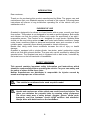
Noise emitted by machinery and equipment (Minibike BLATA QUADARD) - Measurement of emission sound pressure levels at a work
station and at other specified positions. Levels measured by authorized person ( TUV CZ s.r.o.). Test record (no. : 815/90/06/BT/IZ/H) is
deposited with producer.
RPM
2600 rpm (idling speed)
11 000 rpm
Average level of the acoustic pressure A at
a work station (ČSN EN ISO 11202)
LAeq = 79,6 dB
LAeq = 96,3 dB
Total average level of the acoustic power
(ČSN EN ISO 3744)
LWA [dB (A)] = 86,6 dB
LWA [dB (A)] = 104,1 dB
QUADARD
INSTRUCTION MANUAL
TABLE OF CONTENTS
Page
INTRODUCTION................................................................................................................................ 2
PURPOSE OF USE ........................................................................................................................... 2
SAFETY WARNING .......................................................................................................................... 2
TECHNICAL SPECIFICATIONS ....................................................................................................... 3
UNPACKING AND SETTING UP BEFORE RIDING - Fig. 1 ........................................................... 4
BEFORE STARTING THE ENGINE.................................................................................................. 4
ENGINE STARTING - Fig. 2 ............................................................................................................. 5
CARBURETOR - Fig. 3 ..................................................................................................................... 5
RIDING............................................................................................................................................... 6
INSPECTION AND MAINTENANCE................................................................................................. 6
DRIVE CHAIN ADJUSTMENT .......................................................................................................... 7
CENTRIFUGAL CLUTCH SHOES REPLACEMENT ....................................................................... 7
REAR BRAKE ADJUSTMENT - Fig. 4............................................................................................ 7
REAR BRAKE PADS REPLACEMENT ........................................................................................... 8
WHEEL REMOVAL – Fig. 14............................................................................................................ 8
TYRE CHANGE – Fig. 14 ................................................................................................................. 8
AIR FILTER CLEANING .................................................................................................................. 9
PINION REPLACEMENT - Fig. 5...................................................................................................... 9
FRONT AXLE ALIGNMENT.............................................................................................................. 9
STORAGE PROCEDURE ................................................................................................................. 9
QUADARD – assembly – Fig. 6............................................................................................... 10, 11
REAR BRAKE – assembly – Fig. 7 ............................................................................................... 12
ENGINE COMPLETE – Fig. 8 ......................................................................................................... 13
FRONT AXLE – Fig. 9, REAR AXLE SHAFT – Fig. 10 ................................................................. 14
BUMPER – Fig. 11, FRONT STEERING ROD – Fig. 12................................................................ 15
BODY KIT, GAS TANK – Fig. 13, FRONT AND REAR WHEEL – Fig. 14 ................................... 16
QUADARD – SPARE PARTS LIST ........................................................................................... 17,18
TORQUE SETTINGS....................................................................................................................... 19
CERTIFICATE OF WARRANTY ..................................................................................................... 20
1
INTRODUCTION
Dear customer,
Thank you for purchasing this product manufactured by Blata. The proper care and
maintenance that your Quadard requires is outlined in this manual. Following these
instructions will ensure a long trouble-free operating life of the vehicle and your
satisfaction with it.
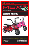
PURPOSE OF USE
Quadard is designed to be driven on closed tracks with an even, smooth, and dustfree surface. This product is not designed to be used on public highways. Both adults
and children can ride the vehicle (children only under the supervision of an adult /
responsible person. This Product is not designed for rough terrain. Minibike Blata
should not be used during winter season and under bad weather conditions. Usage
under these conditions leads to abnormal mechanical wear and corrosion of most
minibike parts - especially those directly exposed to climatic influences.
Beside that, riding under these conditions increase the risk of injury or health
damage.
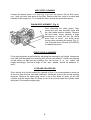
Quadard is equipped with a single-cylinder, two-stroke, petrol combustion engine
with an air filter and exhaust silencer. The gear ratio can be modified by altering the
sprocket sizes. The Quadard rear axle is equipped with a disk brake, controlled by
the brake lever on the left hand side of handlebars.
SAFETY WARNING
This manual contains important safety information and instructions which
should be read carefully before operating the vehicle. For your own safety and
the safety of others follow these rules.
Neither manufacturer nor distributor is responsible for injuries caused by
unsafe and improper use of the vehicle.
This vehicle is not allowed to be used on public roads!
Unsafe and careless use of the vehicle can result in serious injuries. The
driver can minimize the potential risks by wearing safety equipment.
The driver must wear a safety helmet, goggles, gloves, elbow pads,
kneepads, and firm footwear. Avoid rough surfaces and obstacles.
Always drive with both hands on the handlebars.
2
TECHNICAL SPECIFICATIONS
ENGINE
DISPLACEMENT
POWER OUTPUT
TORQUE
CARBURETOR
IGNITION
STARTING
CLUTCH
FRAME
BRAKE
WHEEL RIMS
TYRES
front
rear
front
rear
FUEL
FUEL TANK CAPACITY
WEIGHT
WEIGHT (incl. packing)
CARRYING CAPACITY
DIMENSIONS
length
width
height
BOX PACKING
length
DIMENSIONS
width
height
one cylinder; two-stroke; air-cooled
39,9 ccm
2,5 kW at 8 700 rpm
3,5 Nm at 6 000 rpm
Dell’Orto 14
Contact-less
Manual – hand pull type
Centrifugal automatic
welded high-strength steel tubes
rear disk – disk diameter 119 mm ( 4,7“ )
light alloy 4“ - 51
light alloy 4“ - 95
3,00 – 4“
3,00 – 4“
mixture of petrol (91 octane or higher) and synthetic oil
2T (mixing ratio 50 : 1) 100 millilitres of oil to 5 litres of
petrol.
{After running in period of 5 tanks of fuel at 30 : 1}
1 litre ( 0,26 US gal. )
29 kg ( 63,8 lb. )
33 kg ( 72,6 lb. )
95 kg (209 lb. )
1 010 mm ( 39,7“ )
590 mm ( 23,2“ )
630 mm ( 24,8“ )
106,0 cm ( 41,3“ )
62,0 cm ( 24,4“ )
56,0 cm ( 22, 04“ )
3
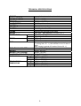
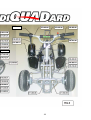
UNPACKING AND SETTING UP BEFORE RIDING
Your Quadard is packed with folded handlebars and brake lever. After unpacking,
set up the handlebars to a comfortable position. After setting-up the handlebars,
tighten the handlebar bolts (M6), the brake lever bolt, and the throttle grip bolt
according to Fig.1. While tightening the bolts, do not use an excessive force.
Overtightening the bolts may cause damage of the threads or other parts. Verify the
smooth and free movement of both control cables (throttle and brake).
Fig. 1
5
2
1
3
4
Controls :
1. Handlebar bolts
2. Brake lever bolt
3. Throttle grip screw
4. Engine stop switch
5. Rear brake lever
1
BEFORE STARTING THE ENGINE
Engine and performance : It is important for the vehicle to be properly run in. The
engine is considered properly run in after consuming five fuel tanks full of mixed
petrol. During the running in period use a 30 : 1 pre mix 2-stroke synthetic oil.
(166 millilitres of oil to 5 litres of petrol )
Once the engine is run in ( Five fuel tanks full ) you can then change the mixture to
50:1 ratio.
(100 millilitres of oil to 5 litres of petrol )
Always mix your oil and petrol in a seperate container making sure it is mixed
properly before filling the fuel tank.
During the running in period, do not use full throttle and do not allow the engine to
overheat, otherwise you will damage your engine.
Check the tyre pressure which should not exceed 2,5 bar
Always inspect the bike before each ride (refer to the article ‘INSPECTION
AND MAINTENANCE’). Failure to inspect and maintain your Quadard
properly increases the risk of an accident or damage to the vehicle.
4
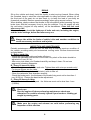
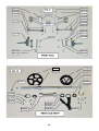
ENGINE STARTING
Fill the fuel tank with pre mix fuel and refit the fuel cap. Open the fuel cock , turning it
to the position “ON”, Fig. 3. Set the choke to open (position “B“, Fig. 3). Without
turning the throttle grip, gently pull the starter rope twice and then on the third pull,
the engine should start, Fig. 2. Do not pull the starter rope out completely! After a
short period , close the choke (position “A”). Let the engine run to normal operating
temperature. and then If needed, adjust idle speed to tick over (use the adjusting
screw on the carburetor, Fig. 3).
Fuel and fuel vapour are highly toxic and flamable. Always be careful
when handling fuel – it can burn or poison you.
- stop the engine and turn off the fuel tap, keep naked flames and
sparks away from your bike.
- do not smoke near your bike.
- refuel only outdoors in a well ventilated space
- clean up any excess fuel immediately
- keep children and pets away
Fig. 2: Starting
Fig. 3: Carburetor
1
3
A
4
2
5
1. Suction chamber
2. Sleeve screw
3. Carburetor body
4. Adjusting screw of no - load run
5. Float chamber
6. Fuel cock
A – choke lever for ride
B – choke lever for cold - starting
It is necessary to adhere to the following instructions for flange reassembling:
always use a new plastic ring 110.078.00 which is inserted into the flange! Tighten
up the screw with torque 5 Nm.
Use of bigger torque can cause carburetor damage which is not covered by
warranty!! Use of smaller torque can cause slackeing of the carburetor.
Check up the screw tightness after every 5 hours of riding!
5
RIDING
Sit on the vehicle and slowly twist the throttle to start moving forward. When riding
the Quadard, keep in mind the rules applicable to riding four-wheel vehicles (sit on
the front part of the seat; do not lean back; try to keep the load of your body as
forward as possible)! Reduce speed accordingly when going around corners.
When braking, always reduce the throttle to the idle position whilst pressing the rear
brake lever with the necessary force to stop the machine. Turn the engine off with
the red button (‘engine kill stop switch‘) on the handlebars. Close the fuel cock
after every ride!
It is necessary to check the tightness of bolts and nuts, including the engine,
and the brake settings, before and after every use.
Always ride within the limits of vehicle/ rider and weather conditions to
avoid unnecessary accidents and injuries.
INSPECTION AND MAINTENANCE
Periodic maintenance check-ups are the best way to ensure premium condition of
the vehicle, providing safety and economical running costs. Perform these services
as listed below:
A - Before each ride:
- Check the rear brake cable and brake efficiency.
- Check the lubrication and tension of the chain. Any slack of the chain should be
adjusted to 5 mm (0,2 in).
- After every ride clean your Quadard carefully and keep it clean. Do not use
aggressive cleaning detergents.
B - Every 10 hours of riding:
- Check the tightness of all bolts and nuts. Tighten them with a torque wrench only!
For torque figures see the table.
- Wash the air filter in petrol and lubricate it with air filter oil.
- Clean the carburetor float chamber carefully.
- Check the brake pads - the thickness of the brake lining must not be less than 1
mm (0.039 in). Review the basic brake adjustment.
C - Every 50 hours of riding:
- Check the state of the clutch pads - the thickness must not be less than 1 mm
(0.039in).
Check-ups
Shut the engine off when performing maintenance check-ups
otherwise You could be severely injured if your hands or clothing get
caught by moving parts.
Make sure the engine and exhaust are cold before performing any
inspection of this machine
6
DRIVE CHAIN ADJUSTMENT
Loosen the bolts (M5) on the rear axle carrier also loosen (M6) bolt on the rear
brake to allow for tensioning the chain, then adjust by moving the excentric disc on
the axle, the drive chain slack should be 5 mm (0,2 in). making sure not to over
tighten the chain. fasten the (M5) bolts on the axle carrier remembering to tighten the
M6 bolt on the brake.
It is important to lubricate the chain regularly, to avoid excess wear. This will prolong
the lifetime of the chain. it is important to lubricate the chain after every ride and
especially in wet conditions. It is recommended to use a quality chain lubricant. If the
chain needs replacement, then please also check the front and rear sprockets for
wear, replace accordingly.
Riding with a chain in poor condition or improperly adjusted can lead to
serious injury. Always, Inspect, Adjust and Maintain the drive chain
properly before each ride.
CENTRIFUGAL CLUTCH SHOES REPLACEMENT
Remove the chain guard by loosening two bolts (M6). Release the chain and
dismantle it. Loosen the four bolts (M6) holding the cover of the clutch. Release the
engine brace on the frame, and move to one side, remove the whole cover together
with the clutch drum. Use a pair of pliers to draw off the clutch springs and loosen
the pins holding the clutch shoes. Install new clutch shoes and springs (if required).
To re-install the clutch assembly, reverse the sequence as described, and then re
adjust the tension of the drive chain.
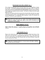
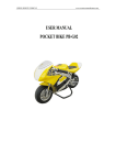
REAR BRAKE ADJUSTMENT (Fig. 4)
5
3
4
General adjustment:
The general brake adjustment can be made
by turning the adjusting screw on the brake
lever on the handlebars.
Basic brake adjustment:
Screw in the adjusting screw at the brake
lever. Loosen the nut (no. 3), and tighten the
adjusting bolt (no. 4), so the wheel cannot
turn. Back off the bolt (no. 4) about ¼ to ½ of
a turn and fix it with the lock nut (no.3).
Do not adjust the cable retainer (no. 5) for
adjusting the brakes!
Failure to inspect and properly maintain the brake increases the risk of
having an accident. Before each ride check the rear brake cable and the
brake efficiency.
7
REAR BRAKE PADS REPLACEMENT (Fig. 7 )
First, screw in the adjusting screw on the left brake lever on the handlebars. Loosen
the nuts (M5 - 914.003.01) holding the brake body to the brake holder, and pull the
brake body, rearward. Do not loosen the cable retainer! Remove the two distance
bushes and the two threaded bushes from the brake body. Detach both halves of the
brake caliper by screwing out the nuts (M6 – 914.010.01). Remove the worn brake
pads 512.054.00.
Place the new brake pad with the pivot hole into the brake half with the control
mechanism and fully screw out the adjusting bolt. Affix the other brake pad carefully
into it’s matching half. To re-install the brake assembly, reverse the sequence as
described. Perform the brake adjustment.
Riding with worn brake pads can reduce the braking performance and
cause an accident. Check and replace brake pads according to the
instructions in this manual.
WHEEL REMOVAL (Fig. 14)
Screw off the front / rear axle nut (M10) and pull off the wheel. To re-install the
wheel, reverse the sequence – install the wheel and tighten the axle nut (M10)
securely.
TYRE CHANGE (Fig. 14)
Remove the wheel (see above). deflate the inner tube. Detach both halves of the
wheel rim by removing the 3 x M6 fixing bolts (M6-914.011.01). Then replace the
tyre and / or inner tube. To re-assemble, reverse the above making sure not to trap
the inner tube and locate the valve correctly also note the tyre direction. Inflate the
tyre to a maximum of 2.5 bar.
Using worn, improperly inflated, or incorrect tyres will reduce stability
and can cause an accident.
8
AIR FILTER CLEANING
Loosen the sleeve screw, no.2 (see Fig. 3) so you can remove the air filter cover,
no.1. Now you have free acces to the filter. Remove the filter, clean it in petrol and
lubricate it with engine oil. To re-install the filter, reverse the procedure above.
PINION REPLACEMENT (Fig. 5)
First, dismantle the chain guard. Then
loosen the rear axle eccentric bolts and
the rear brake reaction catcher. Remove
the drive chain. Insert, carefully, a large
screwdriver or steel rod into the clutch
drum hole, to avoid the clutch drum
turning when releasing the pinion (Fig. 5).
Use a special pinion wrench (319.050.00)
to replace the pinion.
FRONT AXLE ALIGNMENT
Front axle alignment is performed by adjusting the steering tie rod length. Loosen the
nuts (M8) and dismantle the steering joint at both front wheels. Loosen the steering
tie rod safety nut (M8) and by screwing the tie rod end in or out, adjust the
length accordingly. The toe-in angle of the front wheels should be between 0°
and 1°.
STORAGE PROCEDURE
If the vehicle is to be left unused for a period of time, it is recommended to drain out
all the fuel from the fuel tank and carburetor. Inflate the tyres to the normal working
pressure. Remove the spark plug, clean it, put a few drops of motor oil into the
cylinder, pull the starter rope 2-3 times, so an oil film evenly coats the cylinder walls
and piston. Re-install the spark plug.
9
215.045.01
110.001.00
10
215.006.00
217.010.74
11
Fig. 7 – REAR BRAKE - assembly
916.072.02
12
13
217.010.74
14
15
16
MIDI - QUADARD
210.000.00
MIDI - QUADARD
110.001.00
110.001.01
110.002.00
110.004.00
110.004.01
110.004.02
110.004.03
110.005.00
110.006.00
110.006.01
110.006.02
110.006.03
110.008.00
110.011.00
110.015.00
110.017.00
110.019.00
110.020.00
110.022.00
110.024.00
110.028.00
110.031.00
110.032.00
110.053.00
110.055.00
110.056.00
110.057.00
110.059.00
110.060.00
110.063.00
110.065.00
110.067.00
110.068.00
110.069.00
110.069.01
110.069.02
110.069.03
110.070.00
110.072.00
110.073.00
110.074.00
110.076.00
110.077.00
110.078.00
110.080.52
110.097.00
110.098.00
110.099.00
110.100.00
110.101.00
110.102.00
110.103.00
110.104.00
110.105.00
110.185.00
110.216.00
ENGINE
ENGINE COMPLETE
ENGINE PROPER
CARBURETTER SHA 1412L
PISTON COMPLETE - A
PISTON COMPLETE - B
PISTON COMPLETE - C
PISTON COMPLETE - D
PISTON RING
PISTON - A
PISTON - B
PISTON - C
PISTON - D
WRIST - PIN
CRANK BALANCED
CLUTCH DISC
CLUTCH LEVER - 2 PCS
CLUTCH SCREW COMPLETE
CLUTCH SCREW
CLUTCH SPRING - RACING 1,4 - 2PCS
CLUTCH DRUM
CLUTCH CASE
CLUTCH CASE COMPLETE
CLUTCH COMPLETE
ENGINE COVERING
ENGINE SEALING SET
FLANGE
DIAPHRAGM SEALING - 2PCS
DIAPHRAGM
DIAPHRAGM WASHER
SEALING ENGINE BLOCK
ENGINE BLOCK
DIAPHRAGM COMPLETE
SEALING
CYLINDER - A
CYLINDER - B
CYLINDER - C
CYLINDER - D
CYLINDER + PISTON COMPLETE
EXHAUST SEALING
PLASTIC CONECT, FUEL COCK
FUEL COCK
EXHAUST SILENCER COMPLETE
SILENCER MASS
RING
JET 52
FLOAT CHAMBER SEALING
CARBURETOR SEALING 1
ADJUSTING SCREW
THROTTLE VALVE
CARBURETOR FILTER
NEEDLE VALVE
FLOAT
CARBURETOR SEALING 2
THROTTLE VALVE SEALING
JET SET
EXHAUST COMPLETE
17
510.002.00
510.003.00
510.004.00
510.005.00
510.006.00
510.007.00
510.008.00
510.009.00
510.011.00
510.015.00
510.017.00
510.020.00
STARTER COMPLETE
STARTER ROPE
HOLDER
HOLDER
GUIDE BUSH
STARTER CASE
STARTER SPRING
RATCHET WHEEL
WASHER 4,5 x 16 x 1,5
WASHER 8,1 x 16 x 1
WASHER 6,1 x 16 x 1,5
PINION 6
211.001.01
211.005.00
211.030.00
211.040.00
211.048.00
211.058.00
211.066.00
211.067.00
211.082.01
211.083.01
FRAME
FRAME, VARNISHED
DISTANCE SLEEVE, 111 mm
FRONT AXLE
PROTECTIVE BEND
BUMPER
ECCENTRIC HOLDER - REAR
ECCENTRIC , LEFT
ECCENTRIC , RIGHT
FOOTBOARD PLASTIC, LEFT
FOOTBOARD PLASTIC, RIGHT
112.004.00
112.026.20
112.060.00
212.001.00
212.002.00
212.007.00
312.017.00
312.029.00
312.035.00
332.020.00
512.005.00
512.016.50
512.019.01
512.042.00
512.043.00
512.044.00
512.045.00
512.054.00
512.058.00
BRAKES
LIFTER, RIGHT
REAR BRAKE DISC 3,0 x 119
BRAKE COMPLETE
REAR BRAKE HOLDER
SUPPORTING SLEEVE
BOWDEN CABLE - REAR BRAKE
LIFTER LEVER
SPRING, LEFT
WASHER 6,1 x 14 x 3
NUT
HANDLE BAR LEVER, LEFT
TERM. CLAMP BOWDEN
WASHER
DISTANCE SLEEVE
BRAKE PIN
LIFTER PIN
BOWDEN HOLDER
DISC BRAKE PADS - 2PCS
REAR BRAKE CASE - 1 PAIR
113.005.00
113.007.00
213.001.00
213.003.00
213.004.00
213.005.00
213.005.10
213.021.02
213.022.00
213.025.00
513.011.11
513.011.12
WHEELS
TIRE WITH PATTERN 3,00 - 4"
TUBE 3,00 - 4"
DISC 2,0 - 4"
WHEEL COMP. 2,0 - 4" WITHOUT TIRE
WHEEL COMP. 3,8 - 4" WITHOUT TIRE
DISC 3,8 - 4"
DISC 3,8 - 4"
DISTANCE SLEEVE
REAR AXLE SHAFT
SHAFT HUB
DISTANCE SLEEVE 40,3 mm
DISTANCE SLEEVE 46,3 mm
174.004.00
174.007.00
174.022.00
214.001.00
214.002.00
214.003.00
214.006.00
214.012.01
214.015.01
514.008.01
LINING
SEAT - TAIL ASSY, UNPAINTED
SEAT - TAIL ASSY, PAINTED
SADDLE
BODY KIT COMPLETE, UNPAINTED
BODY KIT COMPLETE, PAINTED
FRONT FAIRING, UNPAINTED
FRONT FAIRING, PAINTED
REAR FENDER
CHAIN COVER
RUBBER WASHER 4 x 6,5 x 23,5
175.005.00
175.025.00
175.026.00
215.013.00
215.014.00
215.016.00
215.029.00
215.030.00
215.031.00
215.032.00
215.033.00
215.035.00
215.038.00
215.040.00
215.045.01
515.002.00
215.006.00
515.007.00
515.008.00
CONTROL
HANDLE BAR TUBE
HANDLEBAR BRACKET COVERING
PAD OF COVERING
WHEEL SUSPENSION - R
WHEEL SUSPENSION - L
FRONT STEERING ROD
STEERING TIE ROD
TIE BAR
HANDLEBAR HOLDER
HANDLEBAR WASHER
TIE BAR WASHER
STEERING SEAT ANGLE
TIE BAR BUSH
STEERING SEAT ANGLE COMPLETE
GAS BOWDEN CABLE
HAND GRIPS - 2 PCS
THROTTLE GAS
BOWDEN DUST GUARD
ADJUSTING SCREW
217.010.74
517.001.66
TRANSMISSION
SPROCKET NO. TEETH 74
CHAIN 166
118.001.00
118.002.00
118.003.00
118.005.00
118.010.00
518.001.00
EL. INSTALLATION
SPARK COIL
ROTOR COMPLETE
SPARK PLUG
SPARK PLUG CONNECTOR
ZIP TIES 3,6 x 140
KILL SWITCH
119.003.00
119.005.00
119.006.00
119.010.00
119.011.00
119.035.00
129.008.00
129.017.00
179.008.00
179.009.00
179.012.00
219.002.00
219.020.00
319.050.00
OTHER PARTS
DISTANCE SLEEVE 25,8
CHAIN ROLLER
HOLDER ENGINE
SCREW CAP
RUBBER FOR FRAME
WASHER 6,4 x 18 x 1
HOSE CLAMP
WASHER 6,4 x 16 x 1
TANK WITH CAP
TANK
DELIVERY HOSE
LABEL COMPLETE, ONE MODEL
NUT COVER
PINION KEY
18
912.006.02
914.001.01
914.003.01
914.003.02
914.004.01
914.005.01
914.007.01
914.008.01
914.010.01
914.011.01
914.012.01
914.021.01
914.035.01
914.049.01
914.050.01
914.600.01
915.001.01
915.004.01
915.050.01
916.004.02
916.005.01
916.007.02
916.012.01
916.020.01
916.049.01
916.055.01
916.072.02
920.007.01
920.008.01
920.009.01
920.010.01
920.011.01
920.012.01
920.015.01
920.110.01
930.001.01
930.002.01
930.003.01
930.008.00
930.009.00
930.010.00
940.006.00
950.003.00
950.005.00
950.007.00
950.008.00
950.010.00
950.016.00
960.003.00
960.006.00
960.007.00
960.009.00
960.108.00
970.001.00
970.002.00
JOINING ELEMENTS
SCREW M 5 x 16
SCREW M 5 x 16
SCREW M 5 x 20
SCREW M 5 x 20
SCREW M 5 x 25
SCREW M 5 x 30
SCREW M 6 x 16
SCREW M 6 x 20
SCREW M 6 x 25
SCREW M 6 x 30
SCREW M 6 x 40
SCREW M 6 x 12
SCREW M 6 x 35
SCREW M 10 x 90
SCREW M 10 x 50
SCREW M 8 x 30
SCREW M 4 x 8
SCREW M 4 x 10
SCREW 4,8 x 9,5
SCREW M 5 x 6
SCREW M 6 x 16
SCREW M 5 x 12
SCREW M 6 x 12
SCREW M 6 x 40
SCREW M 5 x 6
SCREW M 5 x 16
SCREW M 5 x 20
NUT M 8
NUT M 5 SELFLOCKING
NUT M 6 SELFLOCKING
NUT M 8 SELFLOCKING
NUT M 10 SELFLOCKING
NUT M 8 LEFT
NUT M 6
NUT M 6 - NO 3201 A
WASHER 5,4
WASHER 6,4
WASHER 10,5
WASHER 5,4
WASHER 6,4
WASHER 8,4
ROLLER 6 x 6
WOODRUFF KEY 3e7 x 3,7
WOODRUFF KEY 2e7 x 3,7
LOCK 15
LOCK 35
PISTON PIN LOCK RING
SPLIT PIN 3,2 x 32
BEARING 6000 ZR
BEARING 6202 C3
BEARING 6202 2ZR
BEARING 6003 Z
CONNECTING ROD BEARING
PACKUNG RING 12 x 22 x 7
PACKUNG RING 15 x 26 x 7
971.055.00
973.050.00
974.050.00
O - RING 9 x 1,8
CIRCULAR MOUNT
PILLOBALL ROD END M8
PART NAME
TORQUE SETTINGS
(1 FT-LB = 1.3558 Nm)
QTY
TORQUE SETTING ( Nm )
ENGINE
Cylinder – Bolts M6
Flange – M5
Starter case – 4
Ratchet wheel –bolt M4
Magneto (rotor) – nut M8
Starter prowls – bolts M5
Ignition coil – boltsM5
Ignition coil holder – bolt M4
Engine block – M6
4
4
3
1
1
2
2
2
5
10
5
3
3
22
5,5
5.5
3
15
Clutch disc – nut M8
Clutch case – bolts M6
Reeds - bolts M3
Float chamber – bolts M4
Slider cover (carburetor) – bolts M4
Pinion - M8
1
4
2
2
2
1
22
10
0,8
2
2
22
FRAME
Front wheel axle - nut M10
Front steering rod – M10
Handlebar holder – M6
Engine holder – M6
Rear wheel axle – nut M10
Rear brake rotor – M5
Sprocket – M5
Footboard plastic
Chain guard –M6
Wheel suspension – nut M 10
Steering tie rod – nut M 8
Front axle – nut M6
Disc – wheel M6
Exhaust – bolts M6
Body and seat – tail assy M6
Rear brake holder M6
Handlebar lever – M5
Throttle clip (handlebar) – M5
Brake mount –M5
1
1
4
3
1
3
3
4
2
2
4
4
3
2
6
1
1
2
2
35
20
10
10
35
20.5
20.5
1.5
9
40
25
10
10
10
6
10
7,5
5
13
19
SECURED BY
Loctite 243
Loctite 243
Loctite 243
Loctite 243
Loctite 243
Self - locking
Self - locking
Self - locking
Loctite 243
Self - locking
Self - locking
Self - locking
Self - locking
Loctite 243
It is a great honour for us that you have chosen our product. Our wish is that
Quadard gives you years of trouble-free enjoyment.
BLATA Company - the manufacturer of your Quadard.
All rights for technical, text and design changes reserved for the BLATA Company.
Serial Number :
CZ ..........................................
Signature of the technical control: ...........................................................
This manual serves also as a CERTIFICATE OF WARRANTY. After receiving the
product, please, check the serial number and the date of purchase. In the case of any claim,
the vehicle should be returned together with this certificate of warranty and proof of
purchase promptly on being found defective, at the purchasers risk and expense, to the
authorized dealer from whom the vehicle was purchased or to the nearest authorized service
dealer. All enquires must be through such dealers and during the period under warranty.
This warranty shall not apply to damage caused through accident, fire, misuse, neglect,
incorrect adjustment or repair, to damage caused through adaptation, modifications, or use
in an improper manner or inconsistent with the technical and/or safety standards.
This warranty shall not apply to tyres, inner tubes, spark plug, drive chain, sprockets,
wheels, brake pads, clutch shoes or other parts of a limited natural life.
Blata company does not quarantee any compensation :
- if the serial number was changed or destroyed
- in case of use of improper fuel, oil, or use of other than original spare parts
- when the vehicle is being used for racing, competitions, promotional purposes,
and/or in vehicle rental shops
- if the claim is not made during the period under warranty
Rights of a purchaser governed by special legislation relating to the purchase of goods are
not violated by granting the warranty.
Date of purchase: ………………………………….
Stamp and signature of the dealer:
20
COPYRIGHT
C
BLATA 2006
Last update: 11.12.2006