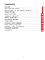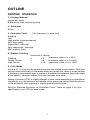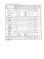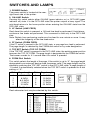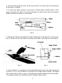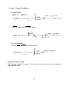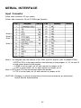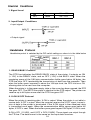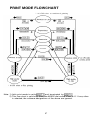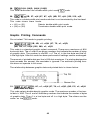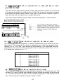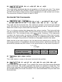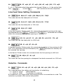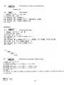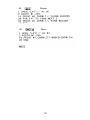
1
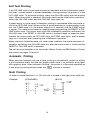
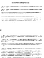
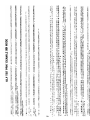
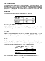
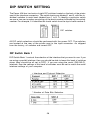
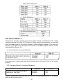
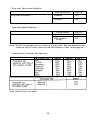
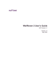
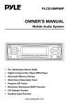
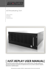
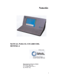
HIGH SPEED
BUSINESS PRINTER
USER’S
GUIDE
EPSON AMERICA INC. SERVICE DIVISION
EPSON
420i
HIGH SPEED BUSINESS PRINTER
Epson America, Inc.
Computer Products Division
2780 Lomita Blvd.
Torrance, CA 90505
(213) 539-9140
WARNING:
“This equipment has been certified to comply with the limits for a Class b
computing device, pursuant to Subpart J of Part 15 of FCC Rules. Only computers certified to comply with the Class B limits may be attached to this printer.
Operation with noncertified computers is likely to result in interference to radio
and TV reception.”
“This equipment generates and uses radio frequency and if not installed and
used properly, that is, in strict accordance with the manufacturer’s instructions,
may cause interference to radio and television reception. It has been tested
and found to comply with the limits for a Class B computing device in accordance with the specifications in Subpart J of Part 15 of FCC Rules, which are
designed to provide reasonable protection against such interference in a
residential installation. However, there is no guarantee that interference will
not occur in a particular installation. If this equipment does cause interference
to radio or television reception, which can be determinded by turning the equipment off and on, the user is encouraged to try to correct the interference by
one or more of the following measures:
•
•
•
•
Reorient the receiving antenna.
Relocate the computer with respect to the receiver.
Move the computer away from the receiver.
Plug the computer into a different outlet so that computer and
receiver are on different branch circuits.
If necessary, the user should consult the dealer or an experienced radio/television technician for additional suggestions. The user may find the following
booklet prepared by the Federal Communications Commission helpful:
“How to Identify and Resolve Radio-TV Interference Problems.”
This booklet is available from the US. Government Printing Office, Washington,
D.C. 20402, Stock No. 004-000-00345-4.
IBM-PC® is a registered trademark of International Business Machines
Corporation.
Copyright© 1985 by Epson America, Inc., Torrance, California 90505
ii
INTRODUCTION
The Epson 420i is a high speed business printer which is usable with almost all commercial software, including word processing and graphics programs. By changing one switch
on the back of the printer, either the Epson Printer mode or the IBM Graphics Printer
mode is selectable. The two modes differ in character sets and some printer commands.
In contrast with the IBM Graphics Printer, the Epson 420i prints italic characters. Most
programs written for the IBM Graphics Printer do not attempt to print them.
The IBM Graphics Printer mode is selected when extended characters are to be used,
or when software is limited for use with the IBM Graphics Printer.
Refer to the sections tied ‘DIP Switch Setting” (page 26), “Code Table” (pages 30 through
32) and “Differences between the Epson Printer Mode and the IBM Graphic Printer Mode”
(page 36) for details on use of each mode.
iii
PRECAUTIONS FOR USE
• When using fan fold paper, the friction lever should be positioned to the front.
• Do not apply undue force to the transparent printer cover.
• Do not use a power supply voltage which is out of the specified range.
• Do not touch the printhead immediately after printing because it is too hot.
• Never close the openings of the upper enclosure or place the printer where these
openings are next to a wall.
• Be careful not to twist the ribbon while installing it.
• Insert the ribbon between the ribbon guide and the printhead as shown in Figure 3.
• Wait at least two seconds after turning power off before turning it back on again.
The initialization process may not be performed correctly if this is not done.
• The printer should be used where the humidity is low, there is little dust, and where
it is not in direct sunlight.
• Do not perform printing without the ribbon cassette and paper properly installed.
EPSON reserves the right to change the contents as stated herein at any time and
without notice. Although every effort has been made to insure that the contents as
stated herein are complete and without error, EPSON cannot be responsible for any
damage that may occur should this not be the case.
iv
CONTENTS
OUTLINE
...............................................................................
SWITCHES AND LAMPS
......................................................
REPLACEMENT OF THE RIBBON CASSETTE
PAPER SETTING
4
6
...................................................................
9
................................................................
13
........................................................
18
..............................................................
22
..........................................................
26
........................................................................
30
MAIN FUNCTIONS
PARALLEL INTERFACE
SERIAL INTERFACE
DIP SWITCH SETTING
CODE TABLE
....................
1
CONTROL CODE SUMMARY
...............................................
33
PRINT MODE FLOWCHART
.................................................
37
CONTROL CODE EXPLANATION
PROGRAM EXAMPLES
APPENDIX
........................................
38
.........................................................
50
........................................................................
v
77
OUTLINE
PRINTING OPERATION
1. Printing Method
Impact dot matrix
Bidirectional logic seeking printing
2. Printhead
8 Pins
3. Character Fonts
(140 characters in each font)
Standard
Italic
High quality (correspondence)
Italic high quality
Superscript / subscript
Italic superscript / subscript
IBM graphics fonts
4. Graphic Printing
Standard
Double-Density
High-Density
Horizontal
n
n
n
x Vertical
(maximum value of n is 816)
x8
(maximum value of n is 1632)
x8
(maximum value of n is 1632)
x 16
5. Print Mode
Any one of 17 fonts may be selected from the five available print modes. Each font
may be used exclusively or intermixed within any given line. When a mode change
is indicated, data already input is printed in the mode first selected, the printer skips
a few spaces, changes mdoes, and then receives new data.
Speed of printout (CPS) is slightly different in each mode depending on operational
complexity, e.g., the bold print and double-strike mdoes are created with two passes
of the printhead, thus requiring a slightly greater printout time.
See the “Detailed Summary of Character Fonts” Table on page 2 for print
specifications and CPS for each mode.
1
Detailed Summary of Character Fonts
2
6.
Paper Feed Function and Form Width
Pin feed method (form width may vary) 5”-15.5”
11”
Friction feed method
7. Line Feed Pitch
Minimum 1/180”
8. Line Feed Speed
60 lines/second - when 6 lines/inch is selected
75 lines/second - when 7.5 lines/inch is selected
9. Copies
Original plus 4 copies, non-carbon, total thickness 0.3mm or less
10. Ribbon
Cassette style, single color
Other Specifications
1. Power Supply
2. Temperature (during operation)
3. Humidity (during operation)
4. External Dimensions
5. Weight
6. Power Consumption
117VAC ± 10%, 220-240VAC ± 10%, 50/60Hz
5°C - 40°C (41°F - 104°F)
20% - 80%
595 mm (width) x 194 mm (height) x 405 mm
(depth)
(23.4 x 7.6 x 15.9 inches)
(The depth is 580mm when the paper rack is
attached.)
27kg (60lb)
Printing 250 watts
Stand-by 5.5 watts
3
SWITCHES AND LAMPS
1. POWER Switch
The power switch is located at the rear,
right-hand side of the printer.
2. ON-LINE Switch
Pressing this switch selects either ON-LINE (green indicator on) or OFF-LINE (green
indicator off) state. If in the OFF-LINE state, the printer outputs a busy signal. The
print-head returns to the home position when entering the ON-LINE state from the
OFF-LINE state.
3. LF Switch (LINE FEED)
Each time this switch is pressed, a 1/6 inch line feed is performed. If held down,
continuous line feeds are performed. This command is valid only in the OFF-LINE
state.
Note: Refrain from performing continuous line feed for one minute or more. It may
affect the longevity of the line feed motor.
4. FF Switch (FORM FEED)
If the FF switch is pressed in the OFF-LINE state, a one page form feed is performed.
The page length is selected by the FORM dial switch or by code designation.
5. TOF SET Switch (TOP OF FORM)
If the TOF SET switch is pressed in the OFF-LINE state, the existing paper position
becomes the TOP OF FORM. The page length is designated by the FORM dial switch.
The buzzer sounds for 0.1 second after this switch is pressed.
6. FORM Dial Switch
This switch selects the length of the page. If the switch is set to “0”, the page length
designated by an external device code, becomes valid. The page length can be
altered by pressing the TOF SET switch in the OFF-LINE state. A page length of
11 inches is automatically selected when the TOF SET switch is pressed for a dial
setting of “0”.
Dial
Page Length
Dial
Page Length
0
1
2
3
4
CODE SET
8 INCH
8.5 INCH
11 INCH
12 INCH
5
6
7
8
9
14 INCH
15 INCH
16 INCH
17 INCH
22 INCH
7. MODE Dial Switch
Each character font may be selected by this switch.
Dial
Code
Selected Character Font
4
Settings 1 to 9 have priority over the software designation. Software selection will be
ignored after setting this switch to 1~ 9. If the switch selection is altered during printing, it will become effective after the current print command is executed.
8. RESET Switch
When this switch is pressed, the printer enters the reset state. When released, the initialization operation is performed once again, This puts the printer in the same condition as at power-on.
9. POWER Lamp (Green)
Lights up when power is on. Blinks if an error has been generated.
10. ON-LINE Lamp (Green)
Data can be input when the printer is the ON-LINE state. The ON-LINE lamp is lit when
the printer is ON-LINE, off when the printer is OFF-LINE. When the printer is OFFLINE, a BUSY signal is output by the printer.
11. P. EMPTY Lamp (Red)
When a paper-empty signal is detected, the P.E. indicator lights and the buzzer sounds
for 3 seconds. At this time, the printer goes OFF-LINE, and the BUSY and P. EMP
signals are output. If paper-empty is detected during printing, operation is terminated
at completion of the line in which the signal is received.
If the ON-LINE switch is pressed after paper is inserted, the P. EMP state is terminated.
If the ON-LINE switch is pressed without new paper inserted, a single line is printed
(during printing the ON-LINE lamp is lit) and the OFF-LINE state is entered again. This
operation can be repeated as many times as desired.
5
RIBBON CASSETTE REPLACEMENT
Installing the Ribbon Cassette
1. Open the printer cover and push the paper pressure bar toward the platen as
shown in Fig. 1.
Fig. 1
6
2. Set the head adjustment lever all the way forward. This lever may be moved easily
by pushing it outward.
3. To attach the ribbon cassette to the printer, hold the ribbon cassette knobs in both
hands and press the ribbon into position between the ribbon mask and the printhead.
Make sure that the ribbon is not twisted.
Fig. 2
4. Tighten the ribbon by twisting the ribbon feed knob in the direction of the arrow
(Fig. 3). Make sure that the ribbon is properly positioned in the guide as shown below.
Fig. 4
Fig. 3
5. The installation is complete once the head adjustment lever has been returned to
position 2, 3 or 4, any of which is a position for a single sheet of paper. The higher
the number that the lever is set on, the greater the distance between head and platen.
This greater distance is desirable since it reduces ribbon wear.
7
Removing the Ribbon Cassette
1. Push the paper pressure bar towards the platen side. Pull the head adjustment
lever forward.
Fig. 5
2. As shown in Fig. 6, hold the ribbon cassette in both hands and pull the ribbon
cassette upward.
Fig. 6
8
PAPER SETTING
1. Rear feed (friction/tractor type)-used for fan-fold form, multiple copy sheets
2. Bottom feed (tractor type)-used for fan-fold, multiple copy sheets
Fig. 7
Fig. 8
Rear Feed Tractor Paper Setting
1. Attach the paper rack to the rear of the printer by inserting it into the two holes
located there, as shown in Fig. 8. Connect the ground wire. It is located between
the paper rack and the power cable receptacle’s right-hand screw (shown in Fig.
8). Failure to do so may cause malfunction of the printer. The purpose of this ground
connection is to eliminate static electricity formed by the paper.
9
2. Pull the paper pressure bar forward. Pull the tractor forward until it clicks. At this
time make sure that the friction lever is in the forward position marked as “PIN FEED.”
(The form is free to move.)
Fig. 9
3. Insert the paper into the back of the printer following the paper feed path 1
as shown in Fig. 7.
Fig. 10
4. Push the tractor into its original position (until it clicks). If the tractor lock levers, located
at either side of the tractor shaft, are pushed up as shown in Fig. 11, the tractor can
be moved horizontally to adjust it to match the width of the form being used.
Fig. 11
10
5. Open both tractor lids, adjust the form holes so they match the tractor pins, and
then close the tractor lids.
6. Determine the proper horizontal positions of the tractors, and then pull the tractor
lock lever forward to lock it into this position.
Fig. 12
7. Push the paper pressure bar towards the platen
8. For one part fan fold paper, the head adjustment lever is usually set at position
2. However, when printing an original plus 4 copies, it should be moved 3 or 4 clicks
forward.
9. As shown in Fig. 13, the side stoppers located at each side of the paper rack’s
form feed roller should be adjusted to match the width of the form being used.
Fig. 13
11
Note 1:
Recommended paper position is shown below.
INCORRECT
CORRECT
Failure to position the paper correctly as shown above may result in a paper jam.
Note 2:
The head adjustment lever on the right base plate is used to find the best
printing quality by shifting it back and forth in line with the paper thickness.
Bottom Feed Tractor Paper Setting
The bottom feed tractor paper setting is illustrated as path 2 in Fig. 7. Because the
form is fed in from the bottom, a special type of desk is required.
1. Pull the paper pressure bar forward and make sure that the friction lever is also
in the forward position marked “PIN FEED”. (Fig. 9)
2. Insert the form as done for path 2 of Fig. 7
3. Move the tractor lock lever upward. (Fig. 11)
4. Perform steps 5-8 for the rear feed tractor type (path 1).
5. Move the side stoppers, located at the bottom of the printer at the paper insertion
opening, to match the width of the paper to be used.
12
MAIN FUNCTIONS
Detection Functions
1. Cover Switch
The printer cover open/close detection switch puts the printer in the OFF-LINE state.
It outputs a BUSY signal when the cover is opened. If the cover is opened during
printing, printing is terminated after the current line is finished, and the OFF-LINE
state is entered. When the cover is closed and the ON-LINE switch is pressed, the
ON-LINE state is entered and printing is resumed. For easier paper and ribbon installation, the printhead moves to the position which is approximately 10 cm away
from the home position when the printer cover is opened.
2. Right Overrun Switch
This switch detects the printhead carrier when it reaches the right most limit.
3. Temperature Detection Function
This detector recognizes abnormal temperature levels within the printer.
Note:
In the case of 2) or 3) if an abnormality is detected, the ERROR and BUSY
signals are output. The printer mechanism’s power supply is also turned off.
To reset this condition, an INITIAL signal must be input, the RESET switch
pressed, or power must be turned off and then on again.
Errors
Buzzer and Power Lamp Blinking
• Abnormal temperature rise
• Pin fires abnormally
• Head carrier
overrun error
• Home sensor
• RAM error
Address (0000) H
(3FFF)H
• RAM error
Address (4000)H
(7FFF)H
You can identify which section is malfunctioning by the buzzer sound or POWER
lamp blinking as shown above.
13
Self Test Printing
If the ON-LINE switch is pressed at power-on and held until the initialization operation ends, a given pattern is printed repeatedly. During printing, the printer is in the
OFF-LINE state. To terminate printing, press the ON-LINE switch until the printing
stops. When the switch is released, the printer performs the initialization operation,
enters the ON-LINE state, and the ON-LINE lamp goes on.
If paper-empty or cover-open is detected, printing is terminated while the printer is
still in the OFF-LINE state. When printing is terminated due to a paper-empty condition, the P.EMP lamp is lit, the buzzer sounds for 3 seconds, and the P.EMP signal
is output. This state can be reset by loading paper and pressing the RESET or ONLINE switch once. The printer then starts the initialization operation and enters the
ON-LINE state. If the RESET or ON-LINE switch is pushed though no paper has been
inserted, the printer enters the OFF-LINE state, the P.EMP lamp lights, and the buzzer
rings for 3 seconds after executing the initialization operation.
When printing is halted because of a cover-open condition, the printer performs initialization and enters the ON-LINE state only after the printer cover is closed and the
RESET or ON-LINE switch is pressed.
The self test print examples in the two modes (Epson Printer and IBM Graphics Printer)
are shown on pages 15 and 16.
Automatic Printing
When data input exceeds one line of data, printing is automatically carried out without
a print command unless the data are graphics data; there is no automatic print signal
with graphics data. After automatic printing, the printer is in the same condition as
it was prior to printing except when the
function is cleared.
Bold Printing
In order to create bold print, a 1/120 inch dot is printed to the right of the initial dot.
Example:
(BOLD)
(STANDARD)
14
SELF TEST PRINT EXAMPLE (EPSON MODE)
16
Double-Strike Printing
In the double-strike mode, the second dot is printed 1/120 inch down from the initial
dot on a vertical line. The double-strike process requires 2 passes of the printhead.
Example:
(DOUBLE-STRIKE)
(STANDARD)
Buffer
This printer is equipped with an 18K-byte communication buffer which allows the
reception of data during printing. Thus, even for large data transfers the computer
is free to perform other tasks.
Printhead Protection
During high-density printing, a heat detector within the printhead protects the coils
from damage due to overheating, by reducing print speed. The sensor recognizes
two temperature warning levels. At level one, a 200 ms pause in the print cycle occurs before the next line is printed. At temperature level two, a 5-second pause in
the print cycle will occur, allowing the heat to dissipate. The ON-LINE lamp blinks
during the 5-second halt.
RAM (Memory) Error Detection
(performed only during the initialization operations)
When a RAM error is detected, the buzzer sounds, the POWER lamp blinks, and
the error state is entered.
17
PARALLEL INTERFACE
Input Connector
Cable side connector
Printer side connector
Signal Diagram
DDK 36 pin 57-30360-D8 or equivalent
DDK 36 pin 57-40360-12 or equivalent
Signal Descriptions
1. Input Signals to the Printer.
* DATA 1-DATA 8
8-bit data signal, with “1” being HIGH.
* STROBE
Strobe signal used to read 8 bits of data. Data is input when the signal is LOW.
* INITIAL
Puts the printer into its initial state. This signal is usually HIGH. When it goes
LOW and then HIGH again, the printer is initialized.
2. Signals from the Printer
* BUSY
This signal shows that the printer is in the BUSY state. When it is HIGH, data
cannot be received. The following are conditions for which a HIGH BUSY signal
is output:
18
(a) While performing initialization operations.
(b) While the printer is inputting data with the STROBE signal.
(c) During self test printing.
(d) When the printer is in the OFF-LINE state. (At this time, the ON-LINE lamp
is not lit: 1) If the printer cover is open; 2) paper supply is depleted or
P.EMPTY lamp is lit; 3) an error is detected or the POWER Lamp is blinking;
4) the ON-LINE switch is pressed.)
An ACK signal is output if the BUSY signal goes LOW only when BUSY is
generated due to conditions l), 2) or 3).
* ACK
This signal that is synchronized with the falling edge of the BUSY signal is output
after the initialization operations at power-on or after data is input.
* P.EMP
This signal goes HIGH when the printer is out of paper.
* ERROR
This signal shows that the printer is in the error state and occurs in the following
circumstances:
(a) If the circuit component’s temperature increases to an abnormal level.
(b) If the right overrun switch is activated.
(c) If current flows through a pin of the printhead when printing is not required.
(d) If the home sensor is not operating properly, during initialization
operations.
(e) If the RAM error is detected, while performing initialization operations.
The sequence of events when an error occurs are as follows:
(a) POWER lamp blinks
(b) ERROR signal goes LOW
(c) BUSY signal goes HIGH
(d) Buzzer is sounded
(e) Power for motion is turned off to terminate operations.
To terminate the error condition:
(a) Turn the power switch OFF and then ON again,
(b) Input the INITIAL signal.
(c) Press the RESET switch.
Electrical Conditions
1. Signal Levels
All signals are TTL level.
HIGH level . . . . . . . . . . . . . . . . . . . . . . . . . . +2.4~5.0V
LOW level . . . . . . . . . . . . . . . . . . . . . . . . . . . . . . . . . . 0~0.4V
19
Measured at the input pins on
the printer.
2. Input / Output Conditions
(a) Input Signals
• INITIAL signal and STROBE signal
(b) Output Signals
• BUSY, ACK, ERROR, P.EMP signals.
3. Signal Cable Length
The maximum length is 2 meters. All the signal lines should be run as twisted pairs
with the GND lines.
20
Timing Chart
(a) Data input
(b) Initialization
DIP Swtich Setting
The parallel interface is selected when DIP switches 1-1 and 1-2 are set as follows:
21
SERIAL INTERFACE
Input Connector
Cable side connector 25 pin (male)
Printer side connector 25 pin D-SUB type (female)
Note 2)
Note 2)
Note 1)
Note 1)
Note 1: As shipped from the factory CTS, DSR, and DC are NC (NO CONNECTION).
If DSR or CD is to be used, perform the following to the jumpers J1, J2, J4 and J5
on the circuit board in the printer.
• If DSR is to be used, cut J2 and connect a jumper at J5.
• If CD is to be used, cut J1 and connect a jumper at J4.
Note 2: RTS and CTS are connected within the printer.
If CTS is to be used, cut J3 and connect a jumper at J6.
CAUTION: Changes in jumper connections should only be made by an authorized
Epson Service representative.
22
Input/Output Signal Descriptions
1. Printer Input Signals
* RD (RECEIVED DATA)
This line is the data reception line for the serial signals from the computer. The data
consists of a start bit, data (parity bit), and stop bit.
Data length 7/8 bits.
With/without parity bit.
Odd/even parity
Selectable by DIP switches
* CTS (CLEAR TO SEND)
A data transmission control signal, NC (No Connection).
OFF: Data transmission may not be performed.
ON: Data transmission is possible.
* DSR (DATA SET READY)
A signal that displays the state of the modem, NC.
OFF: The modem cannot receive/transmit data.
ON: The modem can receive/transmit data.
CD (CARRIER DETECT)
A signal that indicates whether or not the carrier is detected, NC
OFF: No Carrier
ON: Carrier
2. Output Signals from the Printer
*TR (TRANSMIT DATA)
Employed for the X-ON/X-OFF and ETX/ACK control.
* RTS (REQUEST TO SEND)
On (SPACE) state is continuously output.
*SRTS
This is a handshaking signal representing the printer’s BUSY state.
OFF: BUSY
ON: READY
* DTR (DATA TERMINAL READY)
This signal controls the state of the modem.
OFF: Modem transmitting/receiving cannot be performed.
ON: Modem transmitting/receiving can be performed.
23
Electrial Conditions
1. Signal Level
ON
OFF
Space
Mark
+3V ~ +15V
-3V~-15V
2. Input/Output Conditions
• Input signal
• Output signal
Handshake Protocol
Handshake protcol is selected by the DIP switch settings as show in in the table below
1. READY/BUSY Protocol
The DTR line indicates the READY/BUSY state of the printer. It outputs an ON
(+ 12V) in the READY state, and an OFF (-12V) in the BUSY state. When the
remaining space of the 18K-byte communication buffer goes below 4K bytes, the
DTR line turns OFF, terminating the transmission of data from the computer. Then
when the buffer space increases to above the 10K-byte level, the DTR line turns ON,
allowing data to be sent from the computer.
When the printer is in the paper empty state or the cover has been opened, the DTR
line goes OFF. The SRTS line output is identical to the DTR output. The printer can
receive up to 4K bytes more after the DTR line goes OFF.
2. X-ON /X-OFF Protocol
When the printer is receiving data, X-ON is output. When the printer is not able to
receive data, X-OFF is output. When the computer receives the X-OFF signal, transmission of data to the printer is terminated. If the X-ON signal is then received, data
is transmitted once again, When the communication buffer space goes below 4K
bytes, X-OFF is sent. When the buffer space goes beyond 10K bytes, X-ON is sent.
X-ON is DC1 (11 HEX), and X-OFF is DC3 (13HEX). These signals are output through
the TR line. The data format is the same as the input data structure.
24
3. ETXlACK Protocol
The printer sends an ACK (O6HEX) to the computer in response to the data block
separated by ETX (03HEX) which was sent by the computer. If the communication
buffer space goes below 4K bytes, ACK is not sent. If the buffer space is more than
4K bytes, ACK is sent through the TR line. The ACK’s output data format is the same
structure as the input data.
Baud Rate
The following four baud rates are selected by DIP switches,
Data Length 7/8 Bit Selection
A 7 bit or 8 bit data length may be selected by DIP switch 1-3. When the switch
is ON, the 7 bit length is selected. When the switch is OFF, the 8 bit length is selected.
Stop Bit
One bit or more are required for the stop bits. However, when DIP switch 1-3 is ON
and is set to 7 bits, and when there is no parity setting by SW 1-6 and SW 1-7, there
is a need for 2 or more stop bits.
Parity
Whether a parity bit is to be used, and whether odd or even parity is to be used
is selected by SW 1-6 and SW 1-7. If a parity error is generated during the input
of data, whether the data is ignored or a “*” is to be printed, is selected by SW
1-8. If ON, the data is ignored. If OFF, the “*” mark is printed.
No parity
Odd parity
Even parity
SW1 -6
SW1-7
OFF
ON
OFF
ON
OFF
ON
ON
OFF
Note: All DIP switch selections should be performed with the power OFF.
25
DIP SWITCH SETTING
The Epson 420i has two banks of eight DIP switches located on the back of the printer
next to the interface connectors. The switch banks are labeled 1 and 2, with the individual switches in each bank labeled from 1 to 8. To identify a particular switch
we use a two part number consisting of the bank number followed by the switch
number. For example, 2-4 identifies the fourth switch from the top in bank number 2.
BANK 1
BANK 2
DIP switches.
All DIP switch selections should be performed with the power OFF. The switches
are located at the rear of the printer next to the input connector. As shipped
from the factory, all switches are turned OFF.
DIP Switch Bank 1
DIP Switch Bank 1 controls the selection of the interface that you want to use. If you
are using a parallel interface, then you should be able to leave this bank of switches
alone (they should be all set to OFF). If you are using the serial (RS-232-C)
interface, then the settings of this bank of switches must be set to match the serial
interface settings of your computer.
• Interface and Protocol Selection
* Number of Data Bits Selection
26
* Baud Rate Selection
* Parity Selection
* Parity Error Selection
DIP Switch Bank 2
This bank of switches selects some of the other features of the Epson 420i. These
switches may be left in the OFF position as they come from the factory, or you may
wish to change some of the switch settings to select different features. First you must
decide if you want to use the Epson FX mode or the IBM Graphics Printer mode,
determined by Switch 2-4.
* LF (Line Feed) Command Selection
A carriage return is executed when the printhead returns to the print start or left margin
position.
* CR (Carriage Return) Command Selection
SW 2-2
Auto-CR
Execute a carriage return upon
receiving a line feed
Disabled
Enabled
OFF
ON
If SW2-1 and SW2-2 are both set on ON, the CR command and the LF command
perform the same function.
27
* Skip-over Perforation Selection
Skip Perforation
Skip-over perforation
SW 2-3
Disabled
OFF
Enabled
ON
* Operating Mode Selection
Printer Mode
Select operating mode
SW 2-4
Epson Printer
OFF
IBM Graphics
Printer
ON
Note: Switch 2-4 changes several functions of the printer. See the differences between the Epson Printer mode and the IBM Graphics Printer mode (page 36 .)
* International Character Set Selection
Note: Switch 2-8 is not used.
28
The international character set selection does not become valid until the printer
is turned ON once again. The table below shows the international characters:
International Characters
29
CODE TABLE
The control code tables for the Epson and IBM (character set 1 and 2) modes are
shown below.
CODE TABLE (EPSON MODE)
30
CODE TABLE (IBM CHARACTER SET 1)
31
CODE TABLE (IBM CHARACTER SET 2)
Note: Encircled characters are selected by the DIP switches.
32
CONTROL CODE SUMMARY
CATEGORY
PRINT
COMMANDS
ITEM
SYMBOLS
HEX (DECIMAL) CODE
CHARACTER
DESIGNATIONS
CHARACTER
FORMAT
DESIGNATIONS
DOUBLE-WIDTH
MODE
33
FUNCTION
34
Relationship among the font, bold, double-strike and double-width functions is shown
in the table below.
0: Can be used simultaneously
x: Cannot be used simultaneously
The bold and double-strike modes may not be entered simultaneously. The last mode
input has priority.
In all print modes, the double-width mode may be used simultaneously with the bold
or double-strike print modes.
35
Differences between the Epson Printer mode and the IBM
Graphics Printer mode
Selecting one of the two mode (Epson Printer or IBM Graphics Printer mode) changes
several things about the way the Epson 420i operates. The following functions change
when you change the setting of Switch 2-4.
1.
The character set changes. The IBM Graphics Printer mode supports the extended IBM Graphics Printer character set. There are two versions of this
character set and you choose the one you want with Switch 2.7, or with softand
. The IBM character set 2 includes more
ware commands
characters than the lBM set 1 but, otherwise the two sets are the same. The
software commands
and
are Ignored if you are using the
Epson FX printer mode.
The Epson printer mode includes 8 international character sets. Within each set,
12 characters may be different from country to country. You can choose the
set that you want with Switches 2-5, 2-6, and 2-7, or with a software command
. The software command
is ignored if you are using the IBM
Graphics Printer mode.
2.
Two of the commands to set line spacing
ferently with each option.
and
work dif-
command selects
When you choose the Epson printer mode, the
1/6-inch line spacing, and the command selects n/60-inch line
spacing.
When you choose the IBM Graphics Printer mode the
command sets
command. If an
the line spacing to that defined by the
command has not been used, then the
command sets the line spaccommand defines a line spacing of n/60, (but
ing to 1/16-inch. The
command to actually use that spacing.)
must be followed by an
3.
When you are using the IBM Graphics Printer mode, the commands to control
the state of the eighth-bit
and
are ignored.
36
PRINT MODE FLOWCHART
* 16 CPI refers to condensed printing
Note: 1) Italic print mode is set by
and terminated by
2) This flow chart is valid only when the MODE dial switch is set to ‘0’. If any other
is selected, the software designations of the above are ignored.
37
CONTROL CODE EXPLANATION
Print Commands
1.
(0D)H (13)D, (8D)H (141)D
Input of this code initiates printing. DIP SW2-2 indicates whether or not a line-feed
is to be performed after printing. When no print data is input, the printhead does
not move. Print data input after this print command has been performed is printed
at the beginning of the line.
If a line-feed is to be performed and if the
mode) is set, that mode is deleted.
2.
command (double-width character
(0A)H (10)D, (8A)H (138)D
Input of this code results in printing and line-feed. The line-feed width is set by the
line-feed amount command. If no print data has been input, only a line-feed is performed. By setting DIP SW2-1, it is possible to have the data print out start at the
beginning of the next line.
This command terminates the double-width character mode set by the
command.
3.
(0C)H (12)D, (8C)H (140)D
Input of this code results in line-feeds after printing until the top of the next page
is reached. The setting for one page is performed by the switch located at the front
of the printer or by the software designation.
Print data following the
command is printed at the beginning of the line.
The double-width character mode set by the
4.
command is terminated.
(0B)H (11)D, (8B)H (139)D
Input of this code results in a paperfeed until the next vertical tab. If a vertical tab
is not set, this command performs the same operation as the
code. If at least
one vertical tab is set and there is no setting until the next page, a paper-feed is
carried out until the top of the next page is reached.
If the
(double-width character mode) is set, it is terminated.
Setting of a vertical tab is performed by the
5.
or
command.
(1 B, 4A, n)H (27, 74, n)D, (9B, CA, n)H (155, 202, n)D
0 [ n [ 255.n is a binary 8-bit code. Input of this code results in a n/180 inch paperfeed after printing. This line-feed value is not stored within the printer. This starting
position of the next line is at the right side of the line printed previously.
When n
IS
not 0, the
mode is canceled if it is set.
38
Character Designation Commands
6.
(1B, 50)H (27, 80)D, (9B, D0)H (155, 208)D
Input of this code selects the 10 CPI pica print mode.
7.
(1B, 4D)H (27, 77)D, (9B, CD)H (155, 205)D
Input of this code selects the 12 CPI elite print mode.
8.
(0F)H (15)D, (8F)H (143)D
Input of this code selects the 16 CPI standard condensed print mode
9.
(1B, 0F)H (27, 15)D, (9B, 8F)H (155, 143)D
Same as
10.
(1B, 70, n)H (27, 112, n)D, (9B, F0, n)H (155, 240, n)D
This code selects and cancels the proportional print mode.
n = (01)H or (31)H
n = (00)H or (30)H
Selects proportional print mode.
Cancels proportional print mode.
When the proportional print mode is set, the
11.
code and
code are ignored.
(12)H (18)D, (92)H (146)D
This code terminates the condensed print mode.
12.
(1B, 53,00)H (27,83,0)D, (9B,D3,OO)H (155,211,0)D
This code selects the superscript print mode.
13.
(1B, 53,01)H (27, 83, 1)D, (9B,D3,01)H (155,211,1)D
This code selects the subscript print mode.
14.
(1B, 54)H (27, 84)D, (9B, D4)H (155, 212)D
This code terminates superscript / subscript print modes.
39
15.
(1B, 21, n)H (27, 33, n)F
This code allows you to select multiple print styles (i.e., pica-italic-underlined) with
one command. The value of n determines the style selected. To determine a value
of n, add the values given for the print styles that you want to use from the table
below. (Note that some styles can’t be combined.)
Style
Pica
Elite
Proportional
Compressed
Emphasized
Double-Strike
Enlarged
Italic
Underlined
Value
0
1
2
4
8
16
32
64
128
For example, if you want to select elite double-strike Italic print, you would calculate
the value of n like this:
Elite
Double-strike
Italic
n =
1
16
64
81
Character Format Commands
16.
(1B, 45)H (27, 69)D, (9B, C5)H (155, 197)D
This code selects the bold print mode.
This code is invalid in the superscript / subscript print mode. The double-strike mode
is cleared when this code is selected.
17.
(1B, 46)H (27, 70)D, (9B, C6)H (155, 198)D
This code terminates the bold print mode.
18.
(1B, 47)H (27, 71)D, (9B, C7)H (155, 199)D
This code selects the double-strike mode. This code is only valid in pica, elite and
condensed printing of standard and Italic characters. It is invalid in high quality and
superscript / subscript modes. Bold print mode is canceled if it is set.
40
19.
(1B, 48)H (27, 72)D, (9B, C8)H (155, 200)D
This code terminates double-strike mode.
20.
(1B, 58, n)H (27, 88, n)D, (98, D8, n)H (155, 216, n)D
This code selects high quality (correspondence) print mode.
Selects high quality print mode.
n = (01)H or (31)H
Terminates high quality print mode
n = (00)H or (30)H
This code is valid only in standard pica and standard elite print modes.
21.
(1B, 78, n)H (27,120,n)D
This code selects correspondence quality print (n = 1) or draft print (n = 0).
22.
(1B, 34)H (27, 52)D, (9B, B4)H (155, 180)D
This code selects italic print mode.
23.
(1B, 35)H (27, 53)D, (9B, B5)H (155, 181)D
This code terminates italic print mode.
24.
(1B,36)H (27,54)D (IBM mode only)
In the IBM Graphics Printer mode, this command selects the IBM Graphics Printer
character set 2 which includes characters not contained in character set 1.
25.
(1B,37)H (27,55)D (IBM mode only)
In the IBM Graphics Printer mode, this command selects the IBM Graphics Printer
character set 1.
Double-Width Character Printing Commands
26.
(0E)H (14)D, (8E)H (142)D
This code selects double-width print mode. This command is only valid for a single
line of printing. If more than a single line worth of print data is input, the automatic
printing function prints the data. However, after the line-feed is performed, the doublewidth print mode is terminated.
This command is terminated by a linefeed,
27.
Same as the
or
(1B, 0E)H (27, 14)D, (9B, 8E)H (155, 142)D
code.
41
code
28.
(14)H (20)D, (94)H (148)D
This code terminates the double-width print mode
29.
code.
(1B, 57, n)H (27, 87, n)D, (9B, D7, n)H (155, 215, n)D
This code is a double-width print mode code that is not terminated by the line-feed.
This code clears them mode.
n = (01) or (31)
n = (00) or (30)
Selects double-width print mode.
Terminates double-width print mode.
Graphic Printing Commands
Do not select 7-bit mode in graphic printing.
30.
(1B, 4B, n1, n2)H (27, 75, n1, n2)D,
(9B, CB, n1, n2)H (155, 203, n1, n2)D
This code is a standard graphic select command. There are a maximum of 816
horizontal dots. The n1 and n2 are binary numbers that indicate the number of bytes
of graphic data. The number is n2x256 + n1 The n1 is the low byte and the n2
is the high byte. After this code has been performed all settings remain unchanged.
The amount of printable data per line is 816 dots maximum. If a printing designation
input exceeds this amount, the remainder is ignored. The automatic printing function does not operate in this case.
The relationship between graphic data and printed dots is shown below.
31.
(1B, 4C, n1, n2)H (27, 76, n1, n2)D, (9B, CC, n1, n2)H
(155, 204, n1, n2)D
This code selects double-density graphic mode. The maximum number of horizontal dots is 1632. The n1 and n2 are binary numbers that indicate the number of bytes
of graphic data. The n1 is a low byte and n2 is a high byte. The others are the
same as the
code.
42
32.
(1B, 6B, n1, n2)H (27,107, n1, n2)D, (9B, EB, n1, n2)H
(155, 235, n1, n2)D
This code selects high density graphic mode. The maximum number of vertical dots
is 16 and the maximum of horizontal dots is 1632. The n1 and n2 are binary numbers
that display the graphic data number. Note that 16 vertical dots require 2 bytes of
data, but they are considered as a single data block.
The relationship between graphic data and the printed dots is shown below
33.
(1B, 2A, 6D, n1, n2)H (27, 42, 109, n1, n2)D
This command prints dot graphics in a density determined by the value of m (see
table below). The values of n1 and n2 are determined as in the other graphics commands (i.e. n1 + n2* 256 = the number of dot columns). This command must be
followed by the correct number of graphic data (1 byte per column for m = 0 to
6, 2 bytes per column for m = 7).
Value of m
0
1
2
3
4
5
6
7
Function of Command
Same as ESC k
Same as ESC L
Same as ESC Y
Same as ESC Z
Same as ESC K
Same as ESC K
Same as ESC K
Same as ESC k
34.
(1B, 59, n1, n2)H (27, 89, n1, n2)D
This code prints high-speed, double-density dot graphics at 120 dots per inch. The
values of n1 and n2 define the number of bytes of data according to the formula
n1 + n2*256. Each byte of data controls the printhead pins in one vertical row of
dots. The maximum number of bytes of data is 1632.
43
35.
(1B, 5A, n1, n2)H (27, 90, n1, n2)D
This code prints quadruple-density dot graphics at 240 dots per inch. The values
of n1 and n2 define the number of bytes of data according to the formula n1 +
n2*256. Each byte of data controls the printhead pins in one vertical row of dots.
The maximum number of bytes of data is 3264.
Horizontal Tab Commands
36.
(1B, 44, n1, n2, .... nk, 00)H (27, 68, n1, n2,
. . . nk, 0)D, (9B, C4, n1, n2, .... nk, 00)H, (155, 196, n1, n2, .... nk, 0)D
This code sets the horizontal tab. The maximum number of horizontal tab settings
is 28. At power-on, the horizontal tabs are automatically set for every 8th column.
When this code is input, these tabs are cleared.
The n is a binary number that designates the column number. The horizontal tabs
are set in present character width. The horizontal tabs are set in sequence with the
smallest first. The command ends with a
code. However, if the sequence
is made in the reverse order, the setting is terminated at that point. When the horizontal
tabs are set in pica print mode, elite print mode, or condensed print mode, and the
mode is changed, the position of the tabs on the paper remains the same.
When the left or the right margin is set, the tab position already set is cleared. The
left margin position is considered to be the home position, and horizontal tabs are
automatically placed every 8th column in the same manner as they were at power-on.
l [ k [ 28
n ranges
Standard character
Double-width character
37.
Pica
1 [ n [ 135
1 [ n [ 67
Elite
1 [ n [ 162
1 [ n [ 80
Condensed
1 [ n [ 216
1 [ n [ 107
(09)H (9)D, (89)H (137)D
This code causes a move to the next horizontal tab position.
36.
(1B, 51, n)H (27, 81, n)D, (9B, D1, n)H (155, 209, n)D
This code sets the right margin. The n selects the column with the present character
width as the base. This code is ignored if the value of n exceeds a single line. This
code is also ignored if the width between the left and right margins is less then 2
pica double-width print mode characters. This command deletes the print data and
horizontal tabs.
44
39.
(1B, 6C, n)H (27,108, n)D, (9B, EC, n)H (155, 236, n)D
This code sets the left margin, The n selects the column with the present character
width as the base. This code is ignored if the value of n exceeds a single line. This
code clears the print data input already and the horizontal tabs..
If the left and right margins overlap, the one input first is considered valid
Page Length Setting Commands
The length of the page at power-on is selected by the FORM switch.
The following two codes, 40 and 41, are valid only when the FORM switch is set to ”0”,
40.
(1B, 43, n)H (27, 67, n)D, (9B, C3, n)H (155, 195, n)D
1 n [ 127. If n [ 128, this is ignored.
This code selects the page length in line units. The n is the line number. The length
of a page is set by multiplying n by the present line-feed setting for a line. The maximum length of a page allowed to be set is 91 inches.
The paper position at the time this command is performed becomes the head of
the first page. The page length will not change even if a line-feed amount is altered.
41.
195, 0, n)D
(1B, 43, 00, n)H (27, 67, 0, n)D, (9B, C3, 00, n)H (155,
1 [ n [ 22. When n m 23 or n = 0, this is ignored. This code sets the page length
in inches. The n is the number of inches,
Vertical Tab Commands
42.
(1B, 42, n1, n2, .... nk, 00)H (27, 66, n1,
n2, .... nk, 0)D, (9B, C2, n1, n2, .... nk, 00)H (155, 194, n1, n2, .... nk, 00)D
This code sets the vertical tab positions. The n selects the number of lines. The vertical tab is positioned by multiplying the present single line-feed setting for a line by
the set number of lines, The vertical tabs are set in sequence, with the smallest set
first. The code sequence ends with the
code.
A vertical tab is also automatically set at the head of the page
43.
(1B, 62, m, n1, n2, .... nk, 00)H (27, 98,
m, n1, n2, .... nk, 0)D, (9B, E2, m, n1, n2, .... nk, 00)H (155, 226, m, n1, n2,
.... nk, 0)D
0 [ m [ 7. This code sequence set the vertical tabs per channel. The m specifies the
code. The
channel. When m = 0, this code becomes the same as the
method of setting is the same as is done with
45
44.
(1B, 2F, m)H (27, 47, m)D, (9B, AF, m)H (155, 175, m)D
0 [ m [ 7. This code selects the vertical tab channel. When m = 0, the vertical tabs
set by
are used. The
code is used to move to the vertical tab positions.
Line-Feed Value Setting Commands
45.
(1B, 30)H (27, 48)D, (9B, B0)H (155, 176)D
This code sets the line-feed pitch to 1/8 inch.
46.
(1B, 31)H (27, 49)D, (9B, B1)H (155, 177)D
This code sets the line-feed pitch to 7/60 inch.
47.
(1B, 33)H (27, 50)D
In the IBM Graphics Printer mode, this command sets the line spacing to the spacing selected with the
command. If the
command has not been
used, this command sets the line spacing to 1/6 inch.
48.
(1B, 33, n)H (27, 51, n)D, (9B, B3, n)H (155, 179, n)D
This code sets the line-feed pitch to n/180 inch.
49.
(1B, 41, n)H (27, 46, n)D
In the IBM Graphics Printer mode, this command only defines a line spacing of n/60
inch. This command must be followed by the
command to actually set
the selected line spacing.
In the Epson Printer mode, this command sets the line spacing to n/60 inch.
50.
(1B, 2E)H (27, 46, n)D
This code sets the line spacing for subsequent line feed commands to n/120 inch.
Underline Commands
51.
(1B, 2D, n)H (27, 45, n)D, (9B, AD, n)H (155, 173, n)D
This code performs the setting and termination of underlining.
n = (01)H or (31)H
Sets underline.
n = (00)H or (30)H
Termination of underline.
An underline is not output when the printing position is moved due to a tab. The
underline is printed in 9th vertical dot position.
46
Buffer Clear Command
52.
(18)H (24)D, (98)H (152)D
This code deletes the print data that has already been input. However, the control
codes are still valid.
Back Space Commands
53.
(08)H (08)D, (88)H (136)D
This code prints the contents of the buffer. The printing initiation position is moved
to the left by a single character width, determined by the present character width
setting. This code is ignored in proportional print mode.
54.
(1B, 3D)H (27, 61)D (Epson mode only)
In the Epson Printer mode, this code sets the eighth data bit to 0.
55.
(1B, 3E)H (27, 62)D
(Epson mode only)
In the Epson Printer mode, this code sets the eighth data bit to 1.
56.
(1B, 23)H (27, 35)D
(Epson mode only)
In the Epson Printer mode, this command cancels control of the eighth data bit set
by either the set eighth-bit or clear eighth-bit command.
Skip-Over Perforation Commands
57.
(1B, 4E, n)H (27, 78, n)D, (9B, CE, n)H (155, 206, n)D
This code sets skip-over perforation line-feed mode. The n is set in line units. A form
feed to the top of the next page is automatically performed when the remaining lines
on the present page is less than n.
Setting DIP SW2-3 allows the selection of a 1 -inch skip-over perforation mode. This
command has priority over the DIP switch setting.
58.
(1B, 4F)H (27, 79)D, (9B, CF)H (155, 207)D
This code terminates the skip-over perforation mode.
47
Data Delete Command
59.
(7F)H (127)D, (FF)H (255)D
This code deletes one character worth of data. This code is ignored during the proportional print mode.
Home Position Command
60.
(1B, 3C)H (27, 60)D, (9B, BC)H (155, 188)D
This code moves the print head to the home position.
International Character Set Command
61.
(1B, 52, n)H (27, 82, n)D
(Epson mode only)
In the Epson Printer mode, this command selects from one of the 8 international
character sets as shown in the table below.
n
Country
0
1
2
3
4
5
6
7
U.S.A.
France
Germany
U.K.
Denmark
Sweden
Italy
Spain
n is binary number.
Buzzer Command
62.
(07)H (07)D, (87)H (135)D
This code causes the buzzer to sound for approximately 1/3 second.
Reset Command
63.
(1B, 40)H (27, 64)D (9B, C0)H (155, 192)D
This code initializes the printer. Data input after this code is not deleted
48
Print Direction Command
64.
(1B, 55, n)H (27, 85, n)D, (9B, D5, n)H (155, 213, n)D
This code selects unidirectional printing from the left to the right. Graphic mode is
also printed unidirectionally.
Selects unidirectional printing
n = (01)H or (31)H
Selects bidirectional logic seeking printing
n = (00)H or (30)H
When power is turned on, or when the RESET switch is pressed, the bidirectional
printing is selected. This function can also be selected by operating switches. If the
FF switch is pressed in the ON-LINE state, the unidirectional printing is selected after
buzzing for 0.1 second. If the LF switch is pressed in the ON-LINE state, the bidirectional printing is selected after 0.1 second of sounding the buzzer.
Paper-Out Sensor On/Off Commands
65.
(1B, 38)H (27, 56)D
This code turns the paper-out sensor off and allows you to print to the bottom of
single sheets of paper.
66.
(1B, 39)H (17, 57)D
This code turns the paper-out sensor on so that it will report when the printer runs
out of paper. This is the default condition.
49
PROGRAM EXAMPLES
50
52
11.
Termination of condensed
13.
Subscript
14.
Termination of superscript/subscript
Refer to 13.
55
15.
Elite, double-strike, italic
16.
Bold
17.
Termination of bold
Refer to 16.
56
18.
19.
Double-strike
Termination of Double-strike
Refer to 18.
57
20.
21.
High quality
High quality ON/OFF
56
22.
Italic
23.
Termination of Italic
Refer to 22.
59
24.
IBM character Set 1
25.
IBM character Set 2
60
26.
Double width
27.
Double-width
Refer to 26.
26.
Termination of double-width
Refer to 26.
29.
Double width
61
30.
Standard graphic
31.
Double-density graphic
32.
High density graphic
62
33.
Selected density dot graphics
63
34.
High-speed, double-density dot graphics
35.
Quadruple-density dot graphics
64
36.
Horizontal tab setting
37.
Horizontal tab
38.
Right margin
65
40.
Page length in lines
41.
Page length in inches
Refer to 3.
42.
Vertical tab setting
Refer to 4.
66
43.
Channel vertical tab setting
44.
Channel selection of vertical tab
Refer to 43
67
45.
1/8 inch line feed
46.
7/60 inch line feed
47.
1/6 inch line feed
88
50.
n/120 line spacing
70
51.
Underline
52.
Buffer clear
53.
Back space
71
54.
8th bit 0 (Epson only)
55.
8th bit 1 (Epson only)
72
56.
8th bit valid (Epson only)
57.
skip-over perforation
73
56.
Termination of skip-over perforation
Refer to 57.
59.
Data delete
60.
Home positioning
61.
International character (Epson only)
75
62.
Buzzer
63.
Reset
76
APPENDIX
INPUT DATA DUMP IN HEXADECIMAL
There is a function of printing input data from a computer in hexadeciamal codes.
Therefore, it is possible to check the data the printer has received. To perform this
function, keep pushing both the LF and the FF switches at power-on till the initialization operation ends. Hereafter, 16 bytes of input data will be printed a line at a time
due to the function of the automatic printing provided. If the number of input data
is less than 16 bytes and it is necessary to print them all, press the ON-LINE switch.
After printing, push the ON-LINE switch again to return to the dump function from
the OFF-LINE state. This function can be terminated by either of the 3 ways shown
below.
(1) Turn power off, wait 2 seconds and then turn it back on again.
(2) Push the RESET switch.
(3) Input the INITIAL signal.
77
LIMITED WARRANTY
Epson America, Inc. hereby warrants that it will repair or replace, at its option, any part of the Epson
product with which this warranty is enclosed which proves defective by reason of improper workmanship
and/or material, without charge for parts or labor, for a period of one (1) year. This warranty period com
mences on the date of original purchase by the buyer other than for purposes of resale, and this warranty
applies only if such original purchase by the buyer was made in the United States,
To obtain service under this warranty you must return your Epson product, properly packaged in its origins
container or an equivalent, to the nearest authorized Epson Service Center or the Dealer from whom the
product was purchased. Any postage, insurance and shipping costs incurred in presenting or sending
your Epson product for service are your responsibility.
The dealer’s original bill of sale or other satisfactory proof of the date of the original buyer purchase o
your Epson product must be made available to obtain service under this warranty.
This warranty applies only if your Epson product fails to funtion properly under normal use and within
the manufacturer’s specifications. Batteries, as well as optional software packages (ROMs) not contained
in the original container of your Epson product, are excluded from coverage under this warranty. This
warranty does not apply if the Epson label or logo, or the rating label or serial number, has been removed
from your Epson product, or if, in the sole opinion of Epson, your Epson product has been damaged
by faulty or leaking batteries not supplied by Epson, or by accident, misuse, neglect, or improper
packing, shipping, modification or servicing by other than Epson or an authorized Epson Service Center
SOME EPSON PRODUCTS HAVE A COMPARTMENT CONTAINING STATIC-SENSITIVE ELECTRONIC
CIRCUITRY. THIS COMPARTMENT IS CLEARLY LABELED. DO NOT OPEN IT! THIS WARRANTY WILL
BECOME VOID IF YOU ATTEMPT TO ADD OR INSERT ANY ROM OR OTHER PART OR DEVICE. IF
ANY OF THESE STEPS IS REQUIRED, BRING YOUR EPSON PRODUCT TO AN AUTHORIZED
EPSON DEALER.
THE DURATION OF ANY IMPLIED WARRANTY OF MERCHANTABILITY, FITNESS FOR A PARTICULAR
PURPOSE, OR OTHERWISE, ON YOUR EPSON PRODUCT SHALL BE LIMITED TO THE DURATlON
OF THE EXPRESS WARRANTY SET FORTH ABOVE. IN NO EVENT SHALL EPSON AMERICA, INC
OR ITS AFFILIATES BE LIABLE FOR ANY LOSS, INCONVENIENCE OR DAMAGE WHETHER DIRECT
INCIDENTAL, CONSEQUENTIAL OR OTHERWISE, AND WHETHER CAUSED BY NEGLIGENCE OF
OTHER FAULT RESULTING FROM BREACH OF ANY EXPRESS OR IMPLIED WARRANTY OF
MERCHANTABILITY, FITNESS FOR A PARTICULAR PURPOSE, OR OTHERWISE, WITH RESPECT TO
YOUR EPSON PRODUCT, EXCEPT AS SET FORTH HEREIN. SOME STATES DO NOT ALLOW LIMITATIONS ON HOW LONG AN IMPLIED WARRANTY LASTS AND SOME STATES DO NOT ALLOW THE
EXCLUSION OR LIMITATION OF INCIDENTAL OR CONSEQUENTIAL DAMAGES, SO THE ABOVE
LIMITATIONS OR EXCLUSIONS MAY NOT APPLY TO YOU.
YOU may reguest information on how to obtain service under this warranty by contacting the Dealer from
whom your Epson product was purchased, or by contacting Epson America, Inc. at the address printed
below:
Epson America, inc.
Service Division
23610 Telo Avenue
Torrance, CA 90505
(213) 534-0360
This warranty gives you specific legal rights, and you may also have other rights which vary from state
to state.
79
EPSON
EPSON AMERICA INC.