1
sat-nms LBRX
L-Band Beacon Receiver
User Manual
Version 2.0 / 2011-11-10
© Copyright
SatService Gesellschaft für Kommunikatiosnsysteme mbH
Hardstrasse 9
D-78256 Steisslingen
www.satnms.com
www.satservciegmbh.de
Tel +49 7738 97003
Fax +49 7738 97005
SatService
Gesellschaft für Kommunikationssysteme mbH
Table Of Contents
Table Of Contents ................................................................................................................................. 1
1 Introduction ........................................................................................................................................ 3
2 Installation ......................................................................................................................................... 5
2.1 Safety Instructions ........................................................................................................................ 5
2.2 Setting the IP Address .................................................................................................................. 5
2.3 Connecting the Receiver ............................................................................................................... 7
2.4 Configuring the Receiver .............................................................................................................. 8
2.5 Mechanical installation ................................................................................................................. 9
2.6 The sat-nms LBRX19 ................................................................................................................... 9
3 Operation ......................................................................................................................................... 11
3.1 The Web-based User Interface ................................................................................................... 11
3.2 Displayed Readings .................................................................................................................... 11
3.3 Operational Parameters .............................................................................................................. 12
3.4 Installation Parameters ............................................................................................................... 14
3.5 Frontpanel Operation .................................................................................................................. 15
3.5.1 Display Mode ....................................................................................................................... 16
3.5.2 The Menu ............................................................................................................................ 17
3.5.3 Editing Numeric Parameters ................................................................................................. 18
3.5.4 Editing Multiple Choice Parameters ...................................................................................... 18
3.5.5 Manual Step Tuning .............................................................................................................. 18
3.5.6 Fault Display ........................................................................................................................ 18
4 Remote Control ................................................................................................................................ 19
4.1 General command syntax ............................................................................................................ 20
4.2 The TCP/IP remote control interface ........................................................................................... 20
4.3 The RS232 remote control interface ............................................................................................ 21
4.4 Parameter list ............................................................................................................................. 21
4.5 One line read via TCP/IP ............................................................................................................ 23
4.6 UDP level distribution ................................................................................................................ 23
4.7 Novella protocol emulation ......................................................................................................... 24
5 Theory of Operation ......................................................................................................................... 26
5.1 Receiver Design ......................................................................................................................... 26
5.2 Processing of Measured Values .................................................................................................. 27
5.3 C/N Measurement ...................................................................................................................... 28
5.4 Frequency Tracking .................................................................................................................... 29
5.5 Signal search .............................................................................................................................. 30
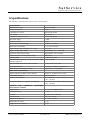
6 Specifications ................................................................................................................................... 32
(C) 2013, SatService GmbH
www.satnms.com
LBRX-UM-1301 Page 1/32
SatService
Gesellschaft für Kommunikationssysteme mbH
(C) 2013, SatService GmbH
www.satnms.com
LBRX-UM-1301 Page 2/32
SatService
Gesellschaft für Kommunikationssysteme mbH
1 Introduction
T he sat-nms L-band beacon receiver manufactured by SatService GmbH is a measurement tool which
measures the RF input level and provides this information as output signal for control systems. The main
application of this receiver is in antenna tracking systems where the receiver provides the tracking signal
level to the antenna step-track controller. Other applications can be pilot measurement and control loops like
uplink power control.
The beacon RX receives a satellite beacon signal which is down-converted to L-Band by a PLL stabilized
Low Noise Converter (LNC) at its L-band interface input. The beacon RX does not demodulate any satellite
because the satellite signals are sometimes CW signals but also very often modulated in FM or BPSK form.
Due to this fact the best implementation is a non-coherent receiver which measures the input level in a user
selectable defined bandwidth and provides this as a dB-linear and calibrated analogue output voltage and
digital information.
The level output is provided by three different and parallel available interface types: a HTTP Web Interface
via an internal Web Server, a RS232 interface or the analog voltage output. The sat-nms beacon receiver is
controlled remotely by a monitoring and control application through the TCP/IP interface. All
communication with the power sensor is made with HTTP get requests. The beacon receiver implements the
'Hypertext Transfer Protocol' (HTTP, RFC-1945) both, for the user interface and for the M&C interface.
This document is the user manual provided with the sat-nms LBRX beacon receiver. It contains all
necessary information how to install, setup and operate the receiver. The user manual is available as a
printed document and for on-line reading on the beacon receiver itself as well.
Version 2.0 / 2011-11-10
The paragraphs below give a short overview to the contents of the documentation. A subset of this
documentation is stored on the device itself, the complete documentation is available on the sat-nms
documentation CD and at www.satnms.com.
Installation: The installation chapter guides through the installation and setup of the LBRX beacon
receiver. It describes the mechanical concept of the receiver box and the assignment of the receiver's
connectors. Finally you learn in this chapter how to set the receiver's IP address, which is a essential
precondition to operate the receiver by means of a web browser. This section is available in the printed
version only.
Operation: T he sat-nms LBRX beacon receiver is operated using a standard web browser like the
Internet-Explorer on MS Windows based computers. The user interface design is straight forward and
clearly structured. Operating the receiver is mostly self-explanatory. Nevertheless, the 'Operation'
chapter outlines the map of web pages which make up the LBRX user interface and elaborately
describes the meaning of each alterable parameter.
Remote Control: The LBRX beacon receiver provides a versatile remote control interface. A
monitoring & control software may fully operate the receiver either through a TCP/IP network
connection or through the RS232 interface of the receiver. This chapter describes the communication
protocol used for remote control and lists all parameters accessible through the remote interface.
Theory of Operation : This chapter gives a short overview how the receiver works. This not only
includes a description of the receiver's electronic concept and the methods of temperature or frequency
response compensation implemented in it. It also describes the the algorithms which implement the
'frequency tracking' and 'noise measurement' functions of this device. Knowing about the theory
regarding this functions helps to find the best parameter settings for a given application.
Specifications: At the end of the document, the specifications applicable to the sat-nms LBRX beacon
receiver are summarized in this chapter.
Support and Assistance
(C) 2013, SatService GmbH
www.satnms.com
LBRX-UM-1301 Page 3/32
SatService
Gesellschaft für Kommunikationssysteme mbH
If you need any assistance regarding our LBRX beacon receiver, don't hesitate to contact us. We would be
pleased to help you by answering your questions.
SatService GmbH phone +49 7738 9700-3 or -4
Hardstrasse 9
fax +49 7738 97005
78256 Steisslingen www.satnms.com
- Germany -
(C) 2013, SatService GmbH
www.satnms.com
LBRX-UM-1301 Page 4/32
SatService
Gesellschaft für Kommunikationssysteme mbH
2 Installation
This chapter describes how to install the sat-nms LBRX beacon receiver. You find a guide how to connect,
configure and mechanically mount the receiver below.
Before you start, please first read the Safety Instructions chapter below. It contains some important
recommendations to prevent damage from the receiver.
Then, we strongly recommend to do a first setup of the receiver on a lab desk before installing it at it's final
location. This is mainly for two reasons:
1. To setup the receiver's IP parameters, the PC used for configuring and the receiver must either be
connected to the same Ethernet hub or must be connected directly with a crossover cable. The
initialization program does not work through routers intelligent network switches.
2. The receiver may be configured to inject a 14/18V power supply voltage at it's RF input. If you plan
to connect the receiver to a signal source which is not able to accept this D/C voltage, you must ensure
that the voltage is switched off before you connect the receiver to that signal source.
Hence, the typical sequence of tasks when putting an sat-nms LBRX beacon receiver into operation is as
follows:
1.
2.
3.
4.
5.
Read the chapter Safety Instructions
Set the receiver's IP address
Check the LNB voltage setting
Mechanically mount the receiver
Connect the receiver to it's signal source, the power supply and the Ethernet network.
In chapter '2.6 The sat-nms LBRX19' you find some additional information about the installation of the 19"
mountable variant of the sat-nms beacon receiver.
2.1 Safety Instructions
Failure to observe all Warnings and Cautions may result in personnel injury and/or equipment damage not
covered by the warranty.
Follow standard Electrostatic Discharge (ESD) procedures when handling an Power Sensor Unit.
Select and apply the appropriate 24V D/C voltage according to the data sheet and documentation
before connecting power.
Before you connect the L-Band Beacon Receiver to an L-Band distributor or LNC , please make sure
that the unit to which you connect can handle 18V D/C voltage on its RF L-Band output. Some LBand IF distribution equipment does not have D/C blocks included and the unit could be damaged. If
you are not sure how the interfacing equipment will behave, switch off the LNC supply voltage in
the Setup menu before you connect a cable to the L-Band input of the beacon receiver.
The L-Band Beacon Receiver can be damaged if the total RF input power is higher than +10dBm
specified maximum value. Do not connect the RF input of the L-band Beacon Receiver to interfaces
where the total output power is higher than the specified value of the data sheet or indicated on the
Receiver.
In case of a failure do not open the L-Band Beacon Receiver, you will loose warranty, call SatService
GmbH for an RMA number.
Observe normal safety precautions when operating, servicing, and troubleshooting this equipment.
Take standard safety precautions with hand and/or power tools.
When connecting the receiver's fault relay circuits, observe the maximum ratings: 120V D/C, 100mA.
The fault circuits are Photo MOS semiconductor relays which will immediately damaged when
connected to higher voltages than specified.
2.2 Setting the IP Address
(C) 2013, SatService GmbH
www.satnms.com
LBRX-UM-1301 Page 5/32
SatService
Gesellschaft für Kommunikationssysteme mbH
Before you can operate the beacon receiver, you need to set the receiver's IP address. There is a special
configuration program on the documentation CD shipping with the receiver for this purpose. We
recommend to configure the receiver's TCP/IP settings before you install the receiver at it's final place. To
configure the receiver, the following equipment is required:
The sat-nms LBRX beacon receiver itself
A 24V D/C power supply
A Computer running a Microsoft Windows operating system equipped with CD-ROM drive and
Ethernet network card.
A CAT5 crossover network cable or a Ethernet hub and standard network cables to connect the
beacon receiver and the computer.
The CD-ROM shipping with the sat-nms receiver.
Setting the receivers IP parameters now is easily done within a few minutes.
1. First install a network cable between the receiver and your computer. If you have a crossover cable
available, this is very easy: simply put the cable into the network connectors of computer and beacon
receiver. Without a crossover cable, you need to connect both, the computer and the beacon receiver
to the same network hub using two standard network cables. It is essential, that the computer and the
receiver are connected to the same network segment, the configuration program is not able to find the
beacon receiver through routers or network switches.
2. Now power on your computer and connect the beacon receiver to the 24V D/C supply.
3. Insert the CD-ROM into the computer's drive and inspect it's contents through the 'My Computer' icon
on your desktop. Double-click to the 'ChipTool.exe' program in the 'ChipTool' directory.
4. When the ChipTool program is running, type CTRL+F to make the program search the beacon
receiver. The program shows a list containing at least one entry describing the actual network
parameters of the receiver.
5. The serial number shown in the first column of the list, must match the serial number printed on the
receiver's enclosure. If the list stays empty, the beacon receiver is not connected properly. If there are
more entries in the list, the configuration program has found other devices in this network segment
which use the same technology.
(C) 2013, SatService GmbH
www.satnms.com
LBRX-UM-1301 Page 6/32
SatService
Gesellschaft für Kommunikationssysteme mbH
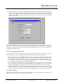
6. Now type CTRL+I to open the IP configuration window of the program. In this form enter the
receiver's serial number, it's new IP address and network mask. If the receiver later shall be operated
through a router, enter the address of the router on the gateway field, otherwise leave this field blanc.
Be sure, that the 'DHCP' mark is unchecked. Finally click to the 'Yes' button to set the new parameters
at the beacon receiver
Now the IP configuration of the receiver is completed. You may finally want to test if the beacon receiver is
reachable now. Start your web browser and type the receiver's IP address into the URL field of the browser.
The beacon receiver should reply with it's main page, provided that the receiver and your computer are
configured for the same subnet.
2.3 Connecting the Receiver
The connectors of the receiver are placed on both sides. One side contains the D/C and Data connectors,
the other side the RF connectors. When you connect the receiver, please consider the following:
The fault relays at J1 are Photo MOS solid state circuits. In fault state or while the unit is powered off
they are in hi-Z state (several MOhms). A resistance below 25 Ohms indicates that the function is OK.
J2 is the Ethernet 10Base-T / RJ45 connector. Use a standard network cable to connect the receiver to
an Ethernet hub. If you want to connect your computer and the receiver directly without using a hub,
you need a crossover cable for this with swapped RX/TX lines.
J3 is a standard 9-pin RS232 (DCE) connector. You may use a direct 9-pin cable to connect a PC to
the beacon receiver. The RTS/CTS and the DTR/DSR lines are bridged in the receiver to simulate
hardware handshaking. They need however not to be connected, if you want to use a 3 wire cable.
The RF input J5 may be configured to power a LNB. If you intend to connect the receiver to a signal
source which may not be able to withstand the LNB supply voltage, be sure to switch off the LNB
supply at the receiver by means of the web based user interface before you connect the receiver input!
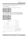
D/C and data connectors
The D/C and data connectors of the receiver all are located at one of the side panels of the enclosure. The
figures below illustrate location of connectors and the pin out.
(C) 2013, SatService GmbH
www.satnms.com
LBRX-UM-1301 Page 7/32
SatService
Gesellschaft für Kommunikationssysteme mbH
J1 pin
no.
J2
Power supply and alarm contacts (SUB- J3 pin
D 9P pin)
no.
RS232 serial interface,
(SUB-D 9P socket)
1
Power supply +24V
1
not connected
2
Power supply +24V
2
TxD (output)
3
not connected
3
RxD (input)
4
GND
4
internally bridged to pin 6
5
GND
5
GND
6
Fault relay (120V D/C, 100mA max.)
6
internally bridged to pin 4
7
Fault relay
7
internally bridged to pin 8
8
Level/Frequency track fault relay (120V
D/C, 100mA max.)
8
internally bridged to pin 7
9
Level/Frequency track fault relay
9
not connected
Ethernet 10Base-T, (RJ45)
J4
DCE,
Beacon level 0..10V (SMA female)
RF connectors
The other side panel of the enclosure contains the RF connectors. These are the RF input which may be
configured to inject a LNB supply voltage of 14 or 18 Volts and the RF output which loops through the input
signal.
J5 RF Input (SMA female)
J6 RF Output (SMA female)
2.4 Configuring the Receiver
This chapter gives a short overview about some configuration parameters you want to set after you have
installed the sat-nms LBRX beacon receiver. A complete reference of all available setup parameters is given
in chapter 3.4 Installation Parameters.
LNB LO Frequencies
The receiver lets you enter the receiver frequency in terms of the RF frequency at the antenna. You have to
configure the LNB conversion frequency at the receiver's setup page. The receiver is prepared to manage
(C) 2013, SatService GmbH
www.satnms.com
LBRX-UM-1301 Page 8/32
SatService
Gesellschaft für Kommunikationssysteme mbH
separate LO frequencies for a lower and a upper band LNB. The setup parameter you have to configure
are:
High band LO frequency
Low band LO frequency
Band edge
If your antenna provides only one single conversion frequency, set this value for both LO frequency
parameters and set the band edge to zero. The receiver also supports applications where the LO frequency is
above RF receive frequency. In this case, enter the LO frequencies as negative values.
LNB Supply Voltage
The receiver is able to supply a LNB through the L-band cable. Set the 'LNB voltage' parameter to the
appropriate value. The special value 'AUTO' enables the LNB supply voltage and switches between 14V
and 18V following the receive polarization you set.
LNB Frequency Band Selection
For antennas switching between frequency bands with a 22kHz tone controlled switch the receiver is able to
generate the 22kHz tone either permanently or automatically depending on the receive frequency. Set the
'22kHz tone' parameter to one of the settings OFF, ON or AUTO.
Relay 2 Function
One of the relay outputs available at the J1 connector may be programmed to act either as a level alarm (the
circuit opens if the receive level falls below a adjustable level) or as a frequency tracking alarm. The latter
indicates that the frequency tracking function does not recognize a trackable signal. This is much like the
'lock alarm' of a coherent receiver.
2.5 Mechanical installation
The receiver enclosure is DIN rail mountable. Hence simply snap the receiver on to the rail to fix it. For
plain wall mount, fix a 270 mm piece of DIN rail at the wall with at least two screws and lock the receiver
on this.
When planning the mechanical installation of the receiver, please consider that the connectors are placed at
the front sides of the enclosure. Depending on the flexibility of the cables you are going to use, you will
require about 10 centimeters space for cabling on both sides of the receiver.
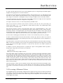
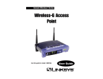
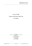
2.6 The sat-nms LBRX19
Connecting the sat-nms LBRX19
T he sat-nms LBRX19 provides an integrated multiswitch, which allows the beacon receiver via its input
frequency and polarization parameters the selection of the corresponding LNC. The input connectors are
named J8.1 ... J8.4. The other connectors J1...J5 are labeled and used the same way as in the DIN-rail
mountable LBRX.
rear view of the sat-nms LBRX19
Using the sat-nms LBRX19 without the integrated Multiswitch
For using the sat-nms LBRX19 without the integrated Multiswitch, you feed the beacon Signal via an SMA
(C) 2013, SatService GmbH
www.satnms.com
LBRX-UM-1301 Page 9/32
SatService
Gesellschaft für Kommunikationssysteme mbH
connector to J5 (Loop In). The LBRX19 provides in this case the possibility to control an external switch
via 14/18V Signal and 22 kHz Tone on/off or just to supply voltage to an LNC.
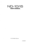
Using the integrated Multiswitch
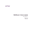
If you like to use the integrated Multiswitch, connect the LNCs with F-type connectors as follows:
LNC
connector
Low Band (11GHz) vertical J8.1
Low Band horizontal
J8.2
High Band (12GHz) vertical J8.3
High Band horizontal
J8.3
J5 (Loop In) and J7 (Loop Out) have to be connected via the corresponding SMA-SMA semi-rigid cable. If
you like the sat-nms LBRX19 to switch automatically to the LNC, the parameters "LNB voltage" and
"22kHz Tone" on the "Settings" page have to be set to "AUTO". The parameter "High band LO frequency",
"Low band LO frequency" and "Band edge" have to be configured as well to allow the LBRX19 the
automatic switching between the different LNCs. For a standard LNC we recommend the following settings:
Parameter name
Setting
LNB voltage
AUTO
22kHz Tone
AUTO
High band LO frequency 9750 MHz
Low band LO frequency 10600 MHz
Band edge
11800 MHz
Block diagram
(C) 2013, SatService GmbH
www.satnms.com
LBRX-UM-1301 Page 10/32
SatService
Gesellschaft für Kommunikationssysteme mbH
3 Operation
The sat-nms LBRX beacon receiver is designed to be controlled over a network link using a standard web
browser. This means in practice, that the user interface to the receiver appears in your browser window after
you type in the receiver's IP address in the address field of the browser program.
Operating the receiver is mostly self-explanatory.
3.1 The Web-based User Interface
After having connected the LBRX to a power supply and set the receivers IP address, you can access the
receiver's user interface. To do this, start your favorite web browser program (Internet Explorer, Netscape
Navigator, Opera or what else Program you prefer). At the address field, where you normally enter the URL
of a web page you want to see, type in the IP address of the sat-nms LBRX receiver you want to control.
The receiver shows a web page consisting of a navigation bar at the left side of the browser window and the
actual readings of the receiver in the main part of the window. The readings automatically refresh once a
second.
The navigation bar at the left contains five buttons which build the receiver's main menu:
Readings This button switches back to the receivers main page you already see when you connect to the
receiver. This page displays the actual readings of the receiver.
Settings
By clicking to this button you switch to the 'Settings' page where you can view and change the
common operational settings of the receiver like frequency or bandwidth.
Setup
This button switches to the 'Setup' page which lets you inspect or change less common
parameters which usually are set only once to adapt the receiver to it's working environment.
Info
After a mouse click to this button, the beacon receiver shows a table with information like the
serial number of the device or the revision ID and compilation date of the software.
Help
Clicking to this button shows the on-line version of this user manual
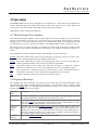
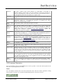
3.2 Displayed Readings
The 'Readings' page is the main page of the beacon receiver which shows the actual measurement values
and some important settings. Parameter settings reported here, are for information only. To change a setting
switch to the Settings page. The 'Readings' page automatically refreshes once a second. The table below
describes the information shown by this page:
Parameter
Name
Description
Input level
This is the actual signal level at the receiver's L-band input. When operating on one of the
C/N measurement modes, this field shows the actual C/N or C/N0.
Frequency
This is the frequency the receiver is tuned to. Depending on the LO frequency settings
made on the Setup page, the frequency value either shows the true RF frequency received
by the antenna or the L-band frequency at the receiver's input.
Frequency
tracking
offset
This value shows the actual frequency tracking offset, the receiver applies to the receive
frequency. The true receive frequency used by the receiver is the nominal frequency from
the field above with the offset from this field added. A frequency offset displayed here is
added to the nominal frequency even if the frequency tracking is switched off. Setting a
new nominal frequency value resets the offset to zero.
Frequency
tracking
Shows if the frequency tracking function is actually enabled.
(C) 2013, SatService GmbH
www.satnms.com
LBRX-UM-1301 Page 11/32
SatService
Gesellschaft für Kommunikationssysteme mbH
Attenuation
Shows the actual input attenuator setting.
Measurement Shows the measurement bandwidth actually used by the receiver.
bandwidth
Post detector This is the low pass filter applied to the measured level before the value gets displayed or
filter
sent to the analog output of the receiver. The filter corresponds to the video filter of a
spectrum analyzer.
Noise level
If the receiver operates in one of the C/N measurement modes, this value shows the noise
level the receiver measured with the recent measurement.
Analog
output
voltage
This value shows the voltage the receiver actually outputs at it's analog output port. Please
note that the reading shown here is not calibrated match the true output voltage exactly.
Temperature
The temperature shown is the temperature measured on beacon receiver printed circuit
board. The temperature at this place normally is about 20C above the environment
temperature, hence temperature readings at 65C are not unusual.
Receive
Level Alarm
If the receive level falls below the 'Alarm threshold' set on the Settings page, the receiver
states FAULT here.
Frequency
Tracking
Alarm
If the frequency tracking function is enabled and the tracking algorithm fails to optimize
the receive frequency setting, the receiver reports a FAULT here.
Synthesizer
Lock Alarm
If one of the PLL synthesizers in the receiver does not lock, a FAULT is reported here.
This happens if you tune the frequency out of it's valid range.
D/C Supply The receiver monitors it's internal supply voltages. if one of them is out of range, a
Alarm
FAULT is stated here.
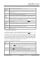
3.3 Operational Parameters
The page 'Settings' contains the receiver's operational parameters. Operational parameters are those which
are assumed to be changed more frequently than the installation parameters on the Setup page.
The page displays a table with the parameters actually set. Each parameter value is a hyper-link to a separate
page which lets you change this parameter. This parameter change page shows the actual parameter setting
either in an entry field or in a drop down box. You may change the parameter to the desired value and then
click to the 'Submit' button to pass the changed value to the receiver. The receiver automatically returns to
the settings page when the parameter has been changed. To cancel a parameter modification you already
started, either use the 'Back' button of you web browser or click to the 'Settings' button on navigation bar.
Both returns to the settings page without changing the parameter you edited.
The table below lists the settings provided by this page.
Parameter
Name
Description
RF
receive This is the receiver's nominal receive frequency. Depending on the LO frequency settings
frequency
made on the Setup page, the frequency value either is expressed as the RF receiver
frequency or the L-band frequency at the receiver's input. If the '22 kHz Tone' setup
parameter is configured as 'AUTO', changing the frequency also may switch the 22kHz
modulation on the LNB power supply on or off.
Polarization
If on the Setup page the 'LNB voltage' parameter is set to 'AUTO', the receive
polarization may be set with this parameter by changing the LNB Voltage.
Attenuation
The receiver provides a switchable input attenuator which lets you adjust the input level
in 10 dB steps. This is specially useful with large Antennas pointing to a satellite which
generate a high flux density. With the attenuator you may adjust the input level in order to
avoid saturation effects in the receiver. All input attenuator steps are calibrated, the
attenuation values are taken into account for the displayed receive level. Available
(C) 2013, SatService GmbH
www.satnms.com
LBRX-UM-1301 Page 12/32
SatService
Gesellschaft für Kommunikationssysteme mbH
attenuator settings are 0, 10, 20 and 30 dB.
Measurement
Bandwidth
The receiver provides four different measurement bandwidth filters (6, 12, 30 and 100
kHz). The 30 kHz filter is suitable for majority of cases.
Post detector The receiver's software applies a low pass filter to the measured level values. This is
filter
much like the video filter at a spectrum analyzer. Available bandwidth settings for this
filter are 0.1 to 5 Hz in 1/2/5 steps. Lower bandwidth settings make the reading more
stable, reduce the fluctuation. Please keep in mind, it will take a noticeable time until the
level reading settles after an input level change with a very low bandwidth setting.
Spectrum
With this parameter set to 'OFF', the receiver's level reading is calibrated for a C/W
Compensation signal. By selecting a modulation type for this parameter, the level display gets
compensated for the selected modulation type.
Alarm
Threshold
With this parameter you set the level threshold. If the measured level falls below this
value, the receiver states a receive level fault. To disable the level alarm, set the threshold
to a very low value, e.g. -120 dBm.
Please note, that the threshold value refers to the signal level, even if the receiver
operates in a C/N measurement mode.
Signal search Setting this parameter to ON enables the automatic signal search function. With signal
enable
search enabled, the receiver searches the signal within the frequency tracking range when
the signal ist lost. Chapter 5.5 Signal search describes this function more detailed.
'SEARCH NOW' starts a search scan immediately, regardles of the enable setting.
Signal search This parameter defines the time, the receiver waits after the signal was lost until a search
delay
scan ist started. The valid range of this parameter is 0 .. 600 seconds.
Frequency
Tracking
This parameter switches the the frequency tracking facility of the receiver ON or OFF. A
description of the frequency tracking facility is given in chapter 5.4 Frequency Tracking.
Frequency
Tracking
Interval
This parameter sets the interval on which the frequency tracking procedure operates. The
value is in seconds. Recommended settings are 15 seconds to tune the receiver quickly to
a frequency you do not know precisely. For normal operation a frequency tracking
interval of one hour (3600 secs) is recommended.
Frequency
Tracking
width
With this setting you limit the frequency offset the frequency tracking procedure may
apply to the nominal frequency. The frequency tracking never tunes the receiver to a
frequency outside the nominal frequency +/- this value, a frequency track fault is
generated if the tracked frequency reaches the limit.
C/N
Noise With this parameter you select if the receiver shall perform a plain input level
measurement measurement or a C/N measurement. A description of the C/N measurement function of
the receiver is given in chapter 5.3 C/N Measurement. You may select one of the
following measurement modes:
OFF The receiver performs a plain level measurement. The Readings page shows the
input level in dBm.
C/N
The receiver measures the signal / noise ratio. The Readings page shows the C/N
in dB.
C/N0 Like the C/N mode, but the receiver normalizes the C/N value to 1 Hz
measurement bandwidth. The Readings page shows the C/N0 in dBHz.
Noise
Measurement
Frequency
With this parameter you specify the frequency at which the receiver shall measure the
noise level at a certain interval. Like with the receive frequency, the LO frequency
settings made at the Setup page are taken into account also for this frequency value.
To get reasonable results with a C/N measurement, you should consider the following:
1. The receiver does not change the LNB frequency band setting when it switches
from the level measurement to the noise measurement. The LNB probably would
change it's gain in this case. The noise measurement frequency hence must be in the
(C) 2013, SatService GmbH
www.satnms.com
LBRX-UM-1301 Page 13/32
SatService
Gesellschaft für Kommunikationssysteme mbH
same frequency band as the receive frequency.
2. Measuring the noise level at the band edge may falsify the result due to the LNB's
band filter. The measured noise level may be too low in this case.
3. You should verify with a spectrum analyzer, that no signal disturbs the noise
measurement at the selected frequency.
Noise
Measurement
Interval
This parameter defines the interval at which the receiver inserts noise measurements in
the C/N modes. The time is specified in seconds. 3600 secs being one hour is a suitable
setting in most cases.
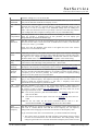
3.4 Installation Parameters
The page 'Setup' contains the receiver's installation parameters. Installation parameters are those which are
assumed to be changed less frequently than the operational parameters on the Settings page.
The page displays a table with the parameters actually set. Each parameter value is a hyper-link to a separate
page which lets you change this parameter. This parameter change page shows the actual parameter setting
either in an entry field or in a drop down box. You may change the parameter to the desired value and then
click to the 'Submit' button to pass the changed value to the receiver. The receiver automatically returns to
the setup page when the parameter has been changed. To cancel a parameter modification you already
started, either use the 'Back' button of you web browser or click to the 'Setup' button on navigation bar.
Both returns to the setup page without changing the parameter you edited.
The table below lists the settings provided by this page.
Parameter
Name
Description
LNB voltage
This parameter controls the LNB supply voltage provided by the receiver at it's input
connector. The following settings are available:
OFF The D/C voltage is completely switched off.
14V
The LNB supply voltage is 14V
18V
The LNB supply voltage is 18V
AUTO The LNB supply voltage is switched on, the voltage depends on the
'Polarization' parameter available on the Settings page. The voltage is
14V for vertical polarization,
18V for horizontal polarization.
22KHz Tone
This parameter controls the presence of a 22 kHz tone on the LNB supply voltage. The
following settings are available:
OFF The 22 kHz tone is switched OFF.
ON
The 22 kHz tone is switched ON.
AUTO The receiver automatically enables the 22 kHz tone depending on the receive
frequency set. The tone is
switched OFF for frequencies below the band edge,
switched ON for frequencies above the band edge.
The band edge is set with the 'Band edge' parameter below.
High band LO This parameter sets the conversion (LO) frequency frequency for the upper frequency
frequency
band LNC. Common values for this frequency are 11300 MHz or 10600 MHz for
consumer antennas. Set this value to zero if you intend to set the receive frequency in
terms of L-band frequency. Normally the receiver assumes, that the LO is below the RF
receive frequency as this is common for Ku-band LNCs. If the LO is above above the
receive frequency (e.g. for a C-Band application) enter the LO frequency as a negative
value.
Low band LO This parameter sets the conversion (LO) frequency frequency for the lower frequency
(C) 2013, SatService GmbH
www.satnms.com
LBRX-UM-1301 Page 14/32
SatService
Gesellschaft für Kommunikationssysteme mbH
frequency
band LNC. Common values for this frequency are 10000 MHz or 9750 MHz for
consumer antennas. Set this value to zero if you intend to set the receive frequency in
terms of L-band frequency. If the LO is above above the receive frequency (e.g. for a
C-Band application) enter the LO frequency as a negative value.
Band edge
This parameter defines the frequency threshold where to switch between the frequency
bands.
Analog
scale
output This parameter defines the slope of the receiver's voltage output in V/dB. The output
voltage has a range of 0 .. 10 V. Setting this parameter to 0.25V/dB lets the analog
output cover a dynamic range of 40 dB.
Analog
offset
output This parameter defines, which input level gives 0V output.
UDP
destination
address
This parameter defines the IP address to which the beacon receiver sends UDP
datagrams with the actual measurement value. Enter the destination IP address in
'dotted quad' notation or the keyword 'none' to prevent the beacon receiver from
sending UDP datagrams. Chapter 4.6 UDP level distribution explains this
communication feature more detailed.
Communication This parameter defines the communication address to be used with the serial interface.
address
You may select an address 'A' .. 'G' for the packet mode communication protocol or
'NONE' to switch the communication mode to a plain text protocol.
Novella
emulation
Relay
function
This parameter sets the communication protocol the receiver provides with the serial
RS232 interface. 'OFF' enables the standard sat-nms communication protocol as
described in chapter 4 Remote Control. Setting the parameter to 'ON' makes the
receiver behave like a Novella beacon receiver. The Novella protocol emulation is
described in chapter 4.7 Novella protocol emulation .
2 This parameter defnes if the beacon receiver shall signal a beacon level fault ('LEVEL')
or a frequency track fault ('FTRACK') at the relay 2 output.
Note
You may enter a note / comment here which is displayed by the beacon receiver as the
heading of the 'Readings' page.
Display refresh
With this parameter you control the display refresh rate of the standard reading / status
web-page. The default setting is 1 second. You may slow down the page refresh down
to once every 30 second with this setting. Setting the refresh rate to 0 disables the page
refresh completely, you may use your borswer's 'reload' button to trigger a page refresh
manually in this case.
User password
Here you can define the password for the 'user' login. Default password is 'user'. When
you are logged in as 'user' you can control the operating parameters at the 'Settings'
page and the fine tuning buttons at the navigation bar. You can't modify the setup
parameters while logged in as 'user'.
Admin
password
Here you can define the password for the 'admin' login. Default password is 'admin'.
When you are logged in as "admin" y o u have full access to all parameters of the
receiver.
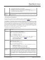
3.5 Frontpanel Operation
The rack mountable version of the sat-nms beacon receiver provides a LCD and a small keyboard at the
front panel for operating the device locally.
Display
The 2-line display normally shows the actual measurement value and some common parameters. During
menu operation it is used to view and edit each individual parameter of the beacon receiver.
(C) 2013, SatService GmbH
www.satnms.com
LBRX-UM-1301 Page 15/32
SatService
Gesellschaft für Kommunikationssysteme mbH
LEDs
Three LEDs at the front panel signal the summary state of the beacon receiver.
The 'Remote' LED is on while the receiver is controlled from a remote computer via network or serial
interface. There is no elusive remote or local lockout mode with the sat-nms beacon receiver. Local
operation of the receiver is still possible while the device is accessed remotely. The 'Remote' LED is
just an information, that someone from remote talks to the device and a local change of parameters
may interfere with this.
The second LED labeled 'Test' shows the 'latched fault' condition. The LED lites on if a Fault/Alarm
occurs and stays on until the operator clears the latched fault (see 3.5.6 Fault Display for details).
The 'Alarm' LED is on while the receiver is in alarm state. This is the same condition which controls
the fault relay output.
Keys
The front panel keyboard provides beside the numeric keys four arrow keys and two keys named ENTER
and CLEAR. The general meaning of the keys remains constant through all levels of the menu:
The ENTER key descends in the menu tree, accepts and stores changed values.
The CLEAR key leaves to higher menu levels, abandons changes when editing parameters. It also
resets the alarm buzzer when in display mode.
The arrow keys navigate in the menu, in some cases they also increment / decrement values.
0 .. 9
The number keys are to enter numeric parameters.
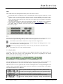
3.5.1 Display Mode
The display mode shows the actual reading and some additional information in the display. This is the
default mode, the beacon receiver enters it automatically after power on. Depending on the selected
measurement mode, the default display looks like this:
level measurement
C/N measurement
C/N0 measurement
The upper display line shows the actual measurement, the lower line shows the receive polarization and
frequency (the polarization is only shown if the LNB voltage is configured for polarization selection).
While the receiver is not in a regular state, the lower line of the display shows a message indicating this. The
ordinary contents of the display and the message are shown alternately, the message 'blinks' on the display.
The following messages may be displayed:
There is a problem with the power supply of the receiver. (hardware fault)
One of the receiver's frequency synthesizers does not lock. (hardware fault)
The receiver had lost the signal, is actually searching it.
The measurement value is below the threshold defined in the settings.
The receiver actually performs a frequency tracking. The measurement
(C) 2013, SatService GmbH
www.satnms.com
LBRX-UM-1301 Page 16/32
SatService
Gesellschaft für Kommunikationssysteme mbH
value appears frozen during this procedure.
The receiver failed to optimize the receive frequency, probably due to a bad
C/N.
If more then one of the above conditions occur, only that one with the highest precedence is shown. This
means for example that the 'SEARCHING' state precedes over the 'THRESH FAULT' which caused the
receiver to search the signal. For a detailed fault report, see chapter 3.5.6 Fault Display
Instead of showing the receive frequency, the lower display line may be set to display more parameters. Use
the arrow keys to step through the available display variants, the 'CLEAR' key resets the display to show the
receive frequency.
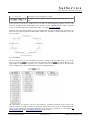
3.5.2 The Menu
The menu mode lets you view and change the receiver's settings. From the display mode, you enter the
menu by pressing the
key. To leave the menu, repeatedly press the
key until the display screen
appears again. If there are no keystrokes for 2 minutes, the receiver automatically leaves the menu and
returns to display mode. The menu structure is shown in the diagram below:
The 'SETTINGS' sub menu lets you view and modify the operational parameters of the receiver. The
'SETUP' sub menu contains a number of parameters which usually only need to be changed during the
beacon receiver installation. For further information about the receiver parameters see the chapters 3.3
Operational Parameters and 3.4 Installation Parameters of this manual.
(C) 2013, SatService GmbH
www.satnms.com
LBRX-UM-1301 Page 17/32
SatService
Gesellschaft für Kommunikationssysteme mbH
To navigate in the menu, use the
to select a sub menu, then press
menu branch. Within the 'SETTINGS' and 'SETUP' sub menus use the
parameter.
Pressing
to descend in the selected
keys to select the desired
one returns to the main menu level, pressing it twice returns to display mode.
3.5.3 Editing Numeric Parameters
To change a numeric parameter like the receive frequency, select this value from the 'SETTINGS' or
'SETUP' menu. The upper display line describes the parameter, the lower line shows it's value:
To set a new value, press
. This clears all figures from the value display and shows '>' at the first
column to signal the editing mode. Using the number keys, you enter the new value. The digits fill the entry
field from right to left, like with a pocket calculator. The
key may be used to delete the last digit.
To accept the edited value, press
. This checks the entered value against it's limits and executes the
parameter change. Pressing
twice (the first key press clears the display) leaves the editing mode without
changing anything.
3.5.4 Editing Multiple Choice Parameters
To change a numeric parameter like the measurement bandwidth, select this value from the 'SETTINGS' or
'SETUP' menu. The upper display line describes the parameter, the lower line shows it's value:
To set a new value, press
. This changes to the editing mode, signalled by a '>' character in the first
column. Use the
keys to change the value.
To accept the changed value, press
. Pressing
leaves the editing mode without changing the value.
3.5.5 Manual Step Tuning
The step tuning page lets you adjust the receive frequency with the arrow keys while watching the receive
level.
From the main menu, select 'STEP TUNE' and press
to enter this mode. The display shows the receive
level (live updated) and the actual receive frequency. The
keys change the frequency in steps of 1
kHz, the
keys perform 10 kHz steps.
If you leave the step tune page by pressing
, the receiver reverts it's receive frequency to the value prior
to the adjustment. To keep the adjusted value as the new receive frequency, press
.
3.5.6 Fault Display
(C) 2013, SatService GmbH
www.satnms.com
LBRX-UM-1301 Page 18/32
SatService
Gesellschaft für Kommunikationssysteme mbH
The fault display page lets you view the actual state of all fault flags and also the latches state of these flags.
From the main menu, select 'FAULTS' and press
to see the faults display. The upper line shows the
momentary active fault conditions, the lower line the latched faults. Active faults are represented by a 2character memnotic, inactive faults by dashes.
DC
There is a problem with the power supply of the receiver. (hardware fault)
SY
One of the receiver's frequency synthesizers does not lock. (hardware fault)
LV
The measurement value is below the threshold defined in the settings.
FT
The receiver failed to optimize the receive frequency, probably due to a bad C/N.
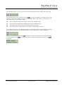
The example below shows a more practical example of a faults display page. It tells that actually everything
is OK, but since the last reset of latched faults the beacon level at least once was below it's threshold.
When you leave the faults display page (
does this), the receiver asks whether to reset the latched faults.
To acknowledge this, press
. To leave the fault display without resetting the latched faults, press
a
second time.
(C) 2013, SatService GmbH
www.satnms.com
LBRX-UM-1301 Page 19/32
SatService
Gesellschaft für Kommunikationssysteme mbH
4 Remote Control
T he sat-nms beacon receiver may be controlled remotely by a monitoring and control application either
through the TCP/IP interface or through a serial RS232 interface. Both communication methods use the
same commands and parameters, however, there are different frames around each message depending
communication method used.
Controlling the device from the web interface, the TCP/IP remote control interface or via the serial interface
is completely equal, commands may sent to any interface at any time, the receiver will use the parameter it
receives last.
4.1 General command syntax
The beacon receiver knows a number of parameters, each identified by a parameter name. To set a certain
parameter to a new value, a message:
name=value
has to be sent to the receiver. The receiver interprets this command, checks the range of value, sets the
internal parameter and then answers:
name=value
The value in the reply is the value actually recognized by the beacon receiver. For instance, if the requested
value was out of range, the replied (and internally used) value is limited to the applicable minimum or
maximum.
To read a parameter from the receiver, instead of a new parameter value a question mark is sent:
name=?
The receiver replies the actual value in a complete message:
name=value
A complete list of the parameter the beacon receiver knows is shown later in this document in chapter
Parameter list. Below, some common rules applying to the remote control message syntax are summarized.
Parameter names always are of lower case letters, most of them are four characters long.
Non-numeric parameter values always are written in upper case.
Numeric (floating point) values may be specified with an arbitrary precision, however the device will
reply only a fixed number of places. The receiver recognizes a decimal point ('.'), numbers must not
contain any commas.
There must not be any whitespace in front or after the '=' in a message.
If the command/query is not of the form name=value or name=?, the receiver replies the message ?
SYNTAX.
If the message syntax is OK, but contains an unknown parameter name is used, the reply is ?
UNKNOWN
Numeric parameters are cut to the limits defined for this particular parameter.
Misspelled choice values cause the receiver to set the first value of the choice list.
Assigning a value to a read-only parameter will cause no fault, however the beacon receiver will
overwrite this parameter immediately or some seconds later with the actual value.
4.2 The TCP/IP remote control interface
Controlling the beacon receiver through the network is done by means of HTTP GET requests. Setting
parameter values or querying readings or settings, all is done by requesting HTTP documents from the
receiver. The message to the receiver thereby is coded into the URL as a CGI form parameter. The receiver
(C) 2013, SatService GmbH
www.satnms.com
LBRX-UM-1301 Page 20/32
SatService
Gesellschaft für Kommunikationssysteme mbH
replies a one line document of the MIME type 'text/plain'.
The document name for remote control is /rmt, hence (assuming the beacon receiver is listening to the IP
address 10.0.0.1), requesting a document with the URL
http://10.0.0.1/rmt?levl=?
will let the receiver reply the actual beacon level in a one line text document:
levl=-52.31
This way all parameters may be queried or set, you may use your favorite web browser to try out the
remote control of the receiver manually.
4.3 The RS232 remote control interface
Beside the network interface, the beacon receiver also provides an RS232 serial port which can be used to
control the device remotely. Depending on the device address set, the receiver either runs framed protocol
with start/stop characters and checksum or it provides a dumb terminal interface. The RS232 interface
always operates at 9600 baud, no parity, 8 data bits, one stop bit.
If an address 'A' .. 'G' is selected, the receiver expects each message it receives to be packed into a frame as
described below.
char # example description
1
{
start character, always '{'
2
A
device address (A..G)
3
l
first character of the message body
.
e
message body ...
.
v
..
.
l
..
.
=
..
n-1
?
last character of the message body
n
}
end character, always '}'
n+1
.
checksum
The checksum byte is calculated using an algorithm as implemented by the following formula:
This protocol type is known as MOD95- or Miteq protocol . The receiver also packs it's reply in a protocol
frame as described above. incomplete frames, checksum errors or address mismatches let the receiver ignore
the message. The time between the characters of a message must be less than 5 seconds or the receiver will
treat the message as incomplete.
If the beacon receiver is set to the device address 'NONE', it uses a simple line protocol instead of the
framed protocol described above. Messages sent to the receiver have to be terminated with a carriage return
character (ASCII 13), the receiver terminates replies with a CR/LF pair (ASCII 13/10). There is no echo for
characters entered, hence this protocol easily may be used for computer based remote control.
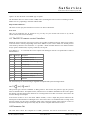
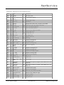
4.4 Parameter list
The table below shows the complete list of M&C parameters the beacon receiver knows. For each
(C) 2013, SatService GmbH
www.satnms.com
LBRX-UM-1301 Page 21/32
SatService
Gesellschaft für Kommunikationssysteme mbH
parameter the valid range and a short description is given.
name
adcv
addr
range
unit
r/o 0 65535
Raw AD/C value
A B C D E F G
NONE
aout
r/o 0.0 .. 10.0
attn
0 10 20 30
bgih
OFF ON
c2n0
r/o 0 .. 99.9
description
Communication address
V
Analog output voltage
dB
Attenuation
Background activities (noise, frequency track) inhibit
dBHz C/N0 ratio in 1Hz, only valid in C/N modes
cnmf
0 .. 40000.000
MHz
Noise measurement frequency
cnmi
1 .. 21600
sec
Noise measurement interval
cton
r/o 0 .. 99.9
dB
C/N ratio, only valid in C/N modes
daco
-200 .. 0
dB
Analog output offset
dacs
-5.0 .. 5.0
V/dB
Analog output scale
dflt
r/o OK FAULT
drfr
0 .. 30
sec
Display refresh rate
edge
0 .. 40000.000
MHz
Band edge
fflt
fltr
D/C supply fault
r/o OK FAULT
Frequency tracking fault
0.1 0.2 0.5 1 2 5
fofs
r/o -1000 .. 1000
freq
depends
settings
ftri
1 .. 21600
ftrk
OFF ON
ftrp
ftrw
on
Post detector filter
kHz
LO MHz
sec
Frequency tracking offset
RF receive frequency
Frequency tracking interval
Frequency tracking mode
r/o 0 1
Frequency tracking in progress
10 .. 1000
kHz
Frequency tracking width
lbfr
r/o 950 .. 2050
MHz
L-Band receive frequency
levl
r/o -999.99 .. 0
dBm
Beacon level
ln22
OFF ON AUTO
lnbv
OFF
14V
AUTO
lof1
-40000.000
40000.000
.. MHz
Low band LO frequency (negative values indicate LO > RF
frequency)
lof2
-40000.000
40000.000
.. MHz
High band LO frequency (negative values indicate LO > RF
frequency)
mmod
OFF C/N C/N0
C/N Measurement mode
msbw
6 12 30 100
Measurement bandwidth
nois
22kHz Tone
18V
r/o -999.99 .. 0
LNB voltage
dBm
Noise level, only valid in C/N modes
note
59 characters max.
The title of the readings web page
novl
OFF ON
Novella emulation
pwda
character string
Admin password
pwdu
character string
User password
(C) 2013, SatService GmbH
www.satnms.com
LBRX-UM-1301 Page 22/32
SatService
Gesellschaft für Kommunikationssysteme mbH
rel2
LEVEL FTRACK
Relay 2 function
rxpl
HV
Polarization
sact
r/o 0 .. 1
scmp
user defined
sdly
0 .. 600
sflt
r/o OK FAULT
sfrc
srno
ssen
Signal search active
Spectrum compensation
sec
Synth fault
1
Force signal search
r/o character string
Device serial number
OFF ON
sver
r/o character string
temp
r/o -40 .. 50
tflt
r/o OK FAULT
thrh
-999.99 .. 0
udpa
xxx.xxx.xxx.xxx
Signal search delay
Signal search enable
Software version
C
Temperature
Threshold fault
dBm
Alarm threshold
UDP destination address
4.5 One line read via TCP/IP
For compatibility with the sat-nms power sensor, the beacon receiver also may be polled for an automated
monitoring by the requesting the 'read' document with a HTTP GET command. Assuming the receiver
listens to the IP address 10.0.0.1, the complete URL for the request is:
http://10.0.0.1/read?fmt=txt
The 'fmt=txt' parameter forces the power sensor to reply a one line text document rather than the HTML
coded page which is normally displayed by the web browser.
The beacon receiver answers a 'text/plain' type document which consist of one line. As shown in the
example below, the line consists of a set of keyword - value pairs, separated by '&' characters. Within each
pair, keyword and value are separated by the '=' character.
levl=-58.33&cton=8.33&c2n0=44.32&fofs=3&adcv=12345&temp=22.5&tflt=OK&fflt=OK&sflt=OK&dflt=OK&sact=0
The format does not use fixed column widths for the values, however the precision of floating point values
is always as shown in the example. An application which parses this string should not rely on the order of
the values in the line. Future version of the receiver may provide additional values which not necessarily will
appear at the end of the line. A description of the parameters is given in the chapter Parameter list above.
4.6 UDP level distribution
Polling the beacon receiver by means of HTTP GET requests via the network interfaces is limited in speed.
The beacon receiver may be polled about three times a second this way. For step track application this may
be too slow.
To overcome this limitation, the beacon receiver provides the capability to distribute the measured level or
c/n value as UDP datagrams. It does this in real time as the values are sampled by the beacon receiver (8
samples per second). The sat-nms ACU/ODM uses this feature.
Protocol Definition
The UDP datagrams are sent to a configurable IP address at port 2000. Each datagram carries the actual
measurement value as a zero-terminated string. Hence, if the beacon receiver is configured to make plain
level measurements, the UDP datagrams contain something like '-65.33' which represents the measured
(C) 2013, SatService GmbH
www.satnms.com
LBRX-UM-1301 Page 23/32
SatService
Gesellschaft für Kommunikationssysteme mbH
level in dBm. In C/No mode, the C/No values is contained in the UDP datagram: e.g. '12.33' for this dBHz
value.
UDP datagrams are sent each time the beacon receiver measures the input level. During frequency track or
while it performs a noise reference measurement, the beacon receiver pauses sending UDP datagrams.
Configuration
To use the UDP feature, enter a valid IP address to the "UDP destination address" field at the Setup page or
set this parameter from remore with the 'udpa' remote parameter. If you want to use the beacon receiver
together with a sat-nms ACU/ODM, set this parameter to the IP address of the ACU.
The beacon receiver starts to send UDP datagrams as soon as it receives a valid destination IP address. To
stop the UDP distribution, set the destination address value to 'none'.
Beside definite IP addresses, the beacon receiver also accepts UDP broadcast masks for the "UDP
destination address" parameter. In this case, the beacon receiver sends the datagrams as UPD broadcasts,
multiple clients may receive the measurement value in this mode. When usinf UDP broadcasts you should
consider the following:
Other computers in the same network which listen to UDP datagrams at port 2000 may be disturbed
by the data send by the beacon receiver.
You must not enable UDP broadcasts for more than one beacon receivers in a network. Receivers of
the UPD messages might fail to distinguish the messages coming from different beacon receivers.
IP routers, also some sorts of switches deny to forward UPD broadcasts unless they are explicitly
configured to do so.
4.7 Novella protocol emulation
The sat-nms beacon receiver provides a Novella remote protocol emulation on the serial RS232 interface.
To enable this mode, at the Setup page set the 'Novella emulation' setup parameter to 'ON'. At the same
place you set the protocol address 'A' ... 'G' (NONE makes no sense as the Novella receiver does not
support a plain terminal protocol).
The Novella protocol emulation replicates the 'operational' parameters of the Novella receiver, They are in
particular:
'S'
status
request
The receiver replies with the Novella status string 'RFxxxxxxxxyyyz' in the given
protocol frame. 'RF' at the beginning states that the receiver is in remote mode.
'xxxxxxxx' is the actual receive frequency in kHz, using a fixed format with leading
zeroes. 'yyy' signals the actual receive level as a 3 digit hexadeciamal number. The value
000 - fff resembles the analog output voltage (0..10V) of the receiver. You may use the
appropriate setup parameters to scale the output for your needs. Finally, the last character
reports the summarized fault status of the receiver. An asterisk ('*') reports a fault, the
underscore character ('_') stands for OK.
'L' set local
Sets the device to local mode. The sat-nms receiver does not distinguish between local
and remote states. It ingores the command and replies it like the Novella receiver with
the statrus string described above.
'R' set
remote
Sets the device to remote mode. The sat-nms receiver does not distinguish between local
and remote states. It ingores the command and replies it like the Novella receiver with
the status string described above.
'F'
set
With this command the receivers frequency is set. The letter F must be followed by the
frequency receive frequency in kHz, formatted as an integer value, 8 digits with leading zeroes.
Unlike the Novella L-band device, the sat-nms beacon receiver applies the the LO
frequencies set at the setup page to this value. If you want to resemble the Novella
receiver exactly, set the LO frequencies to zero.
Other commands are rejected as 'unknown command' by the sat-nms receiver.
(C) 2013, SatService GmbH
www.satnms.com
LBRX-UM-1301 Page 24/32
SatService
Gesellschaft für Kommunikationssysteme mbH
(C) 2013, SatService GmbH
www.satnms.com
LBRX-UM-1301 Page 25/32
SatService
Gesellschaft für Kommunikationssysteme mbH
5 Theory of Operation
The beacon RX receives a satellite beacon signal which is down-converted to L-Band by a PLL stabilized
Low Noise Converter (LNC) at its L-band interface input. The beacon RX does not demodulate any satellite
because the satellite signals are sometimes CW signals but also very often modulated in FM or BPSK form.
Due to this fact the best implementation is a non-coherent receiver which measures the input level in a user
selectable defined bandwidth and provides this as a dB-linear and calibrated analogue output voltage and
digital information.
The level output is provided by three different and parallel available interface types: a HTTP Web Interface
via an internal Web Server, a RS232 interface or the analog voltage output. The sat-nms beacon receiver is
controlled remotely by a monitoring and control application through the TCP/IP interface. All
communication with the power sensor is made with HTTP get requests. The beacon receiver implements the
Hypertext Transfer Protocol (HTTP, RFC-1945) both, for the user interface and for the M&C interface.
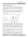
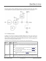
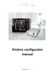
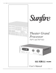
5.1 Receiver Design
The following block diagram shows the functional blocks of the sat-nms L-Band Beacon Receiver.
The L-band input signal is applied to the SMA connector X1. The receive frequency range is from 950MHz
to 2050MHz. A small portion of the input signal is coupled out of the main signal flow, the coupling is
compensated by a small amplifier and this signal is provided as a L-band test output signal with the same
output level at the L-Band test output SMA connector with the same power level for test and measurement
purposes. The L-band signal is filtered within a 950 to 2050MHz filter and then attenuated by a
programmable attenuator in steps of 0dB, 10dB, 20dB or 30dB. After this programmable attenuator a first
amplifier with approximately 20dB of gain and a noise figure of 3.5dB amplifies the signal for the first down
conversion in a 13dBm mixer. This mixer converts the L-band input signal to the first IF of 765MHz by use
of a PLL frequency synthesizer. This mixer is highly linear and determines the overall dynamic range of the
system.
The 765MHz signal is then filtered by use of two 3-pol. ceramic filters which attenuates the out of receive
channel signals. After these two filter stages the 765MHz signal is converted by a second mixer to a 70MHz
IF by use of the fractional-N synthesizer. Direct behind the mixer a SAW filter with approximately 300kHz
bandwidth is used to filter the 70MHz signal. This filter has a very high Q so that only frequencies inside the
bandwidth will be fed to the last mixer circuit.
This mixer converts the 70MHz IF into the final 455kHz IF by use of 1/10 the frequency of the fractionalN synthesizer. The 455kHz IF signal is the fed into a one of four analog multiplexer circuit. Via the internal
micro controller the appropriate bandwidth of 6, 12 30 and 100KHz is selectable. The 6, 12 and 30KHz
filters are ceramic filters the 100kHz filter is due to the high relative bandwidth a discrete filter with inductors
and capacitors. OP-amps behind the filters are used to match the filters with the appropriate impedance and
(C) 2013, SatService GmbH
www.satnms.com
LBRX-UM-1301 Page 26/32
SatService
Gesellschaft für Kommunikationssysteme mbH
are used to provide almost the same level as at the multiplexer input. In a last gain stage the 455kHz signal is
amplified to the appropriate level for the level detector.
The signal level is measured with an logarithmic amplifier. This level detector has a very high dynamic range
and is also very linear. Output of the level detector is a D/C voltage proportional to the L-band input power.
This voltage is converted into a 16bit digital word by an analogue to digital converter with 16bit resolution.
A on board temperature sensor gives the beacon receiver M&C board the knowledge about the temperature
on the RF circuit board and allows fro temperature compensation.
D/C-input to the beacon receiver is +24V/0.5A provided by the M&C board.
There are two D/C-D/C converters on the board to convert the +24V D/C into +6V for the analog +5V
supply and the digital +3.3V / +5V. The digital D/C voltage regulator provides a DC_ERROR signal which
can be read back to the M&C board.
The 2nd D/C-converter is used for the LNB supply which can be programmed either to 14V or 18V.
Furthermore this LNB voltage can be modulated by the Diseq_22kHz signal to provide a DiseqC interface.
The DiseqC interface is not implemented in the first design stage but the hardware basis is given with this
circuit design and the real DiseqC implementation is later on a question of software in the microcontroller
on the beacon receiver M&C board. At the moment only a 22KHz signal is generated if necessary
In cases where no LNB supply is needed the D/C converter can be switched off by the LNC_ON signal.
In order to reduce interference from the microcontroller to the RF part and also to reduce cost on the PC
board production the circuit for the monitoring and control of the L-Band beacon receiver is designed on a
second printed circuit board.
The main interface to the beacon receiver RF board is via the SPI interface. This means that the analog to
digital converter, the temperature sensor and also all monitoring and alarm input and output ports are placed
on the RF board and the digital information is routed via the SPI bus to the M&C board and its
microcontroller.
In addition to that the following interface is provided, the output of the logarithmic detector provides a
analog output voltage which can be used via two interfaces:
Analog output
Output via 16bit analog to digital converter
The analog output voltage is provided to allow the receiver to interface with other manufacturers antenna
control units. The analogue output voltage is generated in the microcontroller in digital form. This does have
the big advantage that all temperature, linearity and slope compensation is also valid for the analogue output
voltage. Also the slope in dB/V and the input level which generates 0V analogue output voltage can be set
via the web browser interface. Via this connector other vendors antenna control units can receive their
beacon level input signal as analog voltage connected to their analog to digital converter in the ACU. The
SMA connector was selected due to space reasons, as a BNC did not fit on the interface side of the L-Band
beacon receiver housing.
This microcontroller controls also the synthesizer and the other hardware selections like bandwidth control.
The microcontroller does provide also a TCP/IP Ethernet port and provides all necessary monitoring &
control data as web interface via HTTP protocol. This allows an easy interfacing with the antenna control
unit.
5.2 Processing of Measured Values
The logarithmic detector circuit outputs a dB-proportional voltage to the A/D converter. Hence the measured
ADC samples reflect directly the receiver's input power in dBm. The readings however are subject to vary
by temperature. There is an absolute offset which changes with the temperature, but also the dB to voltage
relation slightly may change.
(C) 2013, SatService GmbH
www.satnms.com
LBRX-UM-1301 Page 27/32
SatService
Gesellschaft für Kommunikationssysteme mbH
The beacon receiver software compensates this effect by varying the scale and offset values used to
compute the dBm value from the ADC reading. During the factory tests each beacon receiver gets calibrated
at several temperatures. The data processing of the receiver software then works as described below:
5.3 C/N Measurement
In addition to the normal level measurement, the sat-nms LBRX beacon receiver is able to perform C/N
measurements. This is done by measuring the level of the received noise at a frequency other than the
receive frequency in regular intervals. Each measured signal level then gets converted to a C/N value by
referring it to the noise level value. While the receiver measures the noise level, it freezes the displayed C/N
value as well as the analog output voltage for this time.
The behavior of the C/N measurement function is controlled by three operational parameters:
Parameter
Name
Remote
Description
Command
C/N
Noise mmod
measurement
This parameter controls if the receiver shall perform a plain input level
measurement or a C/N measurement. The following measurement modes are
available:
OFF The receiver performs a plain level measurement. The Readings page
shows the input level in dBm.
C/N
The receiver measures the signal / noise ratio. The Readings page
shows the C/N in dB.
C/N0 Like the C/N mode, but the receiver normalizes the C/N value to 1
Hz measurement bandwidth. The Readings page shows the C/N0 in
dBHz.
Noise
cnmf
Measurement
Frequency
(C) 2013, SatService GmbH
This parameter specifies the frequency at which the receiver shall measure the
noise level at a certain interval. Like with the receive frequency, the LO
frequency settings made at the Setup page are taken into account also for this
www.satnms.com
LBRX-UM-1301 Page 28/32
SatService
Gesellschaft für Kommunikationssysteme mbH
frequency value.
To get reasonable results with a C/N measurement, you should consider the
following:
1. The receiver does not change the LNB frequency band setting when it
switches from the level measurement to the noise measurement. The
L N B probably would change it's gain in this case. The noise
measurement frequency hence must be in the same frequency band as
the receive frequency.
2. Measuring the noise level at the band edge may falsify the result due to
the LNB's band filter. The measured noise level may be too low in this
case.
3. You should verify with a spectrum analyzer, that no signal disturbs the
noise measurement at the selected frequency.
Noise
cnmi
Measurement
Interval
This parameter defines the interval at which the receiver inserts noise
measurements in the C/N modes. The time is specified in seconds. 3600 secs
being one hour is a suitable setting in most cases.
5.4 Frequency Tracking
The sat-nms LBRX beacon receiver using it's non-coherent receiver design, does not automatically follow
an input signal drifting in frequency like a PLL receiver would do. To let the receiver compensate effects
like an LNC frequency drift due to temperature or Doppler frequency shift, a frequency tracking algorithm
has been implemented in the receiver.
With frequency tracking enabled, the receiver tunes the receive frequency a small amount up and down at
certain intervals. Such a search step takes less than one second, while the frequency is detuned, the level
reading and the analog output of the receiver stays frozen.
The step size used for a frequency search step depends in the measurement bandwidth, the receiver
automatically selects the appropriate step size. Receiving a C/W signal, the receiver software expects a signal
degradation of 1..3 dB when the frequency has been tuned up or down. The receiver evaluates the signal
center frequency by comparing the measured level, at the old frequency f , at f+d and f-d to the known
shape of the filter.
The behavior of the frequency track facility is controlled by three operational parameters:
Parameter Remote
Description
Name
Command
Frequency ftrk
Tracking
(C) 2013, SatService GmbH
This parameter switches the the frequency tracking facility of the receiver ON or
OFF. Please note, that switching off the frequency tracking does not reset the
frequency offset which is applied by the frequency tracking. To reset the offset,
set the receiver's frequency setting.
www.satnms.com
LBRX-UM-1301 Page 29/32
SatService
Gesellschaft für Kommunikationssysteme mbH
Frequency ftri
Tracking
Interval
This parameter sets the interval on which the frequency tracking procedure
operates. The value is in seconds. Recommended settings are 15 seconds to tune
the receiver quickly to a frequency you do not know precisely. For normal
operation
a frequency tracking interval of one hour (3600 secs) is
recommended.
Frequency ftrw
Tracking
width
With this setting you limit the frequency offset the frequency tracking procedure
may apply to the nominal frequency. The frequency tracking never tunes the
receiver to a frequency outside the specified range, a frequency track fault is
generated if the tracked frequency reaches the limit.
5.5 Signal search
The 'signal search' function enables the receiver to search a signal within the frequency tracking width. A
signal search is triggered either manually or automatically if the signal disappears for a certain time. The
beacon receiver monitors the 'threshold fault' to detect if the signal is present.
When a signal search is initiated, the receiver steps over the frequency range from f-ftrw to f+ftrw in steps
o f 0.8 msbw. The receiver detects at which frequency the highest level is achieved and finally tunes the
receiver to this frequency. The frequency offset of the frequency tracking is adjusted for this, the nominal
frequency remains unchanged. The duration of the search cycle depends on the bandwidth an tracking range
settings, the maximum expected value (bw=6kHz, range = +/- 150kHz) is 1 minute.
The behavior of the frequency track facility is controlled by the following operational parameters:
Signal
search
enable
ssen Setting this parameter to ON enables the automatic signal search function. If the input
signal falls below the alarm threshold for a certain time, a signal search is initiated.
Signal
search
delay
sdly
Alarm
threshold
thrh The threshold value which primarily is used to generate a 'signal missing' fault is very
important for the signal search function. If the measured input level falls below this
threshold for at least sdly seconds, a search cycle is triggered. You must sxet the
threshold to a reasonable value in order to let the receiver detect that the signal is
missing.
This parameter defines the time, the receiver waits after the signal was lost until a
search scan is started. The valid range of this parameter is 0 .. 600 seconds.
Frequency ftrw This also parameter defines the frequency range which is covered by the search
Tracking
procedure. A search cycle always starts at f-ftrw and ends at f+ftrw.
width
Force
search
sfrc
If a 1 is written to this parameter, the receiver immediately starts searching, regardles
of the ssen setting. When operated at with a web browser, clicking to 'SEARCH
NOW' executed this command. Reading back the sfrc parameter always returns an
empty string.
If the receiver is tuned to a new frequency while the signal search function is enabled, the frequency offset
is set to 0 and the receiver operates at this frequency for sdly seconds. If the received signal stays below the
threshold during this time, the receiver starts searching.
After a search cycle has been finished, the receiver is tuned to that frequency which gave the highest level
during the search. If after a short delay for signal settling the receive level still is below the threshold, the
next search cycle starts immediately.
The signal search operates in steps of approx. 80% of the measurement bandwidth. This is to make the
search procedure as fast as possible. The signal frequency therefore is not determined very accurately. If
you have enabled the frequency tracking function at the same time, the receiver performs a frequency track
cycle directly after the signal search. If frequency tracking is switched off, the receiver tuning is left at the
frequency offset the search alorithm has found.
(C) 2013, SatService GmbH
www.satnms.com
LBRX-UM-1301 Page 30/32
SatService
Gesellschaft für Kommunikationssysteme mbH
(C) 2013, SatService GmbH
www.satnms.com
LBRX-UM-1301 Page 31/32
SatService
Gesellschaft für Kommunikationssysteme mbH
6 Specifications
The table below summarizes the beacon receiver's specifications:
RF Specification
Input frequency range
950 to 2050 MHz
Frequency Step Size
1 KHz
L-Band Input Connector
SMA female 50 Ohm
LNC voltage
OFF/14/18V
L-Band Test Output Connector
SMA female 50 Ohm
Input Noise Figure
< 10dB
Frequency accuracy
1*E-6
Input Level measurement range
-40 dBm to -80 dBm
Measurement bandwidths
6, 12, 30 and 100 KHz
Output Voltage range of analogue AGC voltage
0V to 10V
Slope of analog output voltage
programmable, -5.0 .. +5.0 V/dB
0V point of analog output voltage
programmable, -200 to 0 dBm
Output Connector for analog output voltage
SMA female
Linearity failure
+/-1dB in any 10 dB
Switchable input attenuator to adapt the dynamic range 0, 10, 20, 30 dB
and input signal level
Video bandwidth selectable by micro controller
0.1 Hz, 0.5 Hz, 1 Hz, 5 Hz
Large signal behavior
no impact at -35dBm total input power
Digital frequency tracking functionality
programmable +/- Bandwidth
M&C Interface Specification
Ethernet interface for M&C and user interface
10-Base-T, Via HTTP GET requests
RS232 M&C Interface
D-SUB 9 female,
Summary fault indication
Photo MOS relay contact D-SUB 9 male (120
V D/C, 100 mA)
Level alarm indication or frequency tracking alarm
Photo MOS relay contact D-SUB 9 male (120
V D/C, 100 mA)
Electrical
and
Mechanical
Environmental conditions
Specification,
Supply Voltage
22 V to 28 V unregulated D/C
Temperature range
5 to 50 C
Humidity
up to 90% non condensing
DIN rail module
270 x 105 x 50 mm
Rack mount LBRX19
19" x 1HU x 370mm
Weight DIN rail module
1,5 kg
Weight rack mount LBRX19
5.0 kg
(C) 2013, SatService GmbH
www.satnms.com
LBRX-UM-1301 Page 32/32