1
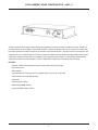
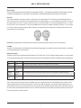
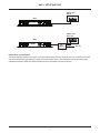
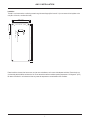
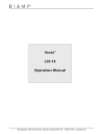
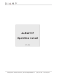
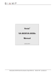
Vocia®
ANC-1
Operation Manual
January 2012
Biamp Systems, 9300 SW Gemini Drive, Beaverton, Oregon 97008 U.S.A. (503) 641-7287 www.biamp.com
IMPORTANT SAFETY INSTRUCTIONS
IMPORTANT SAFETY INSTRUCTIONS
1) Read these instructions.
2) Keep these instructions.
3) Heed all warnings.
4) Follow all instructions.
5) Do not use this product near water.
6) Clean only with dry cloth.
7) Do not block ventilation openings.
Install in accordance with the
manufacturer’s instructions.
8) Do not install near any heat
sources such as radiators, heat
registers, stoves, or other product
(including amplifiers) that produce
heat.
9) Do not defeat the safety purpose of
the grounding-type plug. A grounding
type plug has two blades and a third
grounding prong.
The third prong is provided for your
safety. If the provided plug does not
fit into your outlet, consult an
electrician for replacement of the
obsolete outlet.
10) Protect the power cord from being
walked on or pinched particularly at plugs,
convenience receptacles, and the point
where they exit from the product.
11) Only use attachments/accessories
specified by the manufacturer.
12) Use only with equipment rack, cart,
stand or table designed to provide adequate
mechanical strength, heat dissipation and
securement to the building structure.
When a cart is used, use
caution when moving the cart
and product combination to
avoid injury from tip-over.
13) Unplug this product during lightning
storms or when unused for long periods of
time.
14) Refer all servicing to qualified service
personnel. Servicing is required when the
product has been damaged in any way, such
as power-supply cord or plug is damaged,
liquid has been spilled or objects have fallen
into the product, the product has been
exposed to rain or moisture, does not
operate normally, or has been dropped.
WARNING - To reduce the risk of fire or electric shock, do not expose this product to rain or
moisture.
WARNING - This product employs Safety Grounding and must be connected to a MAINS
socket that is properly grounded to provide a protective earthing connection.
Disconnect Device - The MAINS plug is used to disconnect MAINS power and must be
installed near the equipment and remain readily accessible.
Explanation of safety related symbols - Product labeling and the operation manual may
use the internationally recognized symbols defined below to note safety messages.
Lightning Bolt: Hazardous Live voltages present when this unit is in operation. Do
not touch terminals marked with this symbol while the unit is connected to live power.
Exclamation Point: Replace components (i.e. fuses) only with the values specified by
the manufacturer. Failure to do so will compromise safe operation of this unit.
Standard Important Safety Instructions
2
TABLE OF CONTENTS
VOCIA AMBIENT NOISE COMPENSATION 1 (ANC-1) FEATURES . . . . . . . . . . . . . . . . . . . . . . . . 4
SETUP AND USE . . . . . . . . . . . . . . . . . . . . . . . . . . . . . . . . . . . . . . . . . . . . . . . . . . . . . . . . . . . . . . . . . . . . . . . . . . . . . . . 5-6
Device ID . . . . . . . . . . . . . . . . . . . . . . . . . . . . . . . . . . . . . . . . . . . . . . . . . . . . . . . . . . . . . . . . . . . . . . . . . . . . . . . . . . . . . . . . . . 5
CobraNet . . . . . . . . . . . . . . . . . . . . . . . . . . . . . . . . . . . . . . . . . . . . . . . . . . . . . . . . . . . . . . . . . . . . . . . . . . . . . . . . . . . . . . . . . . 5
Network Connection. . . . . . . . . . . . . . . . . . . . . . . . . . . . . . . . . . . . . . . . . . . . . . . . . . . . . . . . . . . . . . . . . . . . . . . . . . . . . . . . . 5
Ambient Noise Input Connections. . . . . . . . . . . . . . . . . . . . . . . . . . . . . . . . . . . . . . . . . . . . . . . . . . . . . . . . . . . . . . . . . . . . . . 6
INSTALLATION. . . . . . . . . . . . . . . . . . . . . . . . . . . . . . . . . . . . . . . . . . . . . . . . . . . . . . . . . . . . . . . . . . . . . . . . . . . . . . . . . . . . . 7
SPECIFICATIONS & BLOCK DIAGRAM. . . . . . . . . . . . . . . . . . . . . . . . . . . . . . . . . . . . . . . . . . . . . . . . . . . . . . . . 8
WARRANTY . . . . . . . . . . . . . . . . . . . . . . . . . . . . . . . . . . . . . . . . . . . . . . . . . . . . . . . . . . . . . . . . . . . . . . . . . . . . . . . . . . . . . . . . 9
FCC COMPLIANCE. . . . . . . . . . . . . . . . . . . . . . . . . . . . . . . . . . . . . . . . . . . . . . . . . . . . . . . . . . . . . . . . . . . . . . . . . . . . . . 10
EC DECLARATION . . . . . . . . . . . . . . . . . . . . . . . . . . . . . . . . . . . . . . . . . . . . . . . . . . . . . . . . . . . . . . . . . . . . . . . . . . . . . . 11
EU ROHS COMPLIANT . . . . . . . . . . . . . . . . . . . . . . . . . . . . . . . . . . . . . . . . . . . . . . . . . . . . . . . . . . . . . . . . . . . . . . . . . 12
3
VOCIA AMBIENT NOISE COMPENSATION 1 (ANC-1)
The ANC-1 allows the Vocia® system to adjust output levels automatically in response to changes in ambient noise levels. The ANC-1 is
a networked device for use with Biamp’s Vocia Amplifier (VA-8600). It accepts two ambient noise inputs at microphone or line level. Most
high-quality dynamic and condenser microphones can be used in conjunction with the ANC-1. Input gain for each of the two inputs is user
configurable via the Vocia software interface. The ANC-1 processes the ambient noise information using Biamp’s adaptive ambient noise
compensation algorithm and sends data to the VA-8600 to change the output level accordingly. The Vocia software interface permits
comprehensive adjustment of ANC parameters. The ANC-1 utilizes IEEE compliant Power over Ethernet (PoE) technology.
FEATURES
• Automatic, adaptive volume adjustment based on ambient noise sensing and processing
• 48V phantom power
• Wall mountable
• CobraNet audio/control with dynamic use of available bundles, plus power on a single cable
• Power and data over a single Ethernet cable
• Status LEDs
• Sturdy component housing
• CE marked and RoHS compliant
• Covered by BIAMP Systems’ warranty
4
ANC-1 SETUP AND USE
Setup and Use
The Vocia software provides an intuitive interface for configuration of the ANC-1. The information supplied by this manual relates to physical
connections and assignment. For more details on setup of the ANC-1 operational parameters please consult the Vocia Help File.
Device ID
The rotary ID switches are located on the ANC-1 and give the unit a unique Device ID. The switches are in hexadecimal format. All
ANC-1 units must have a unique Device ID to function within a Vocia Paging World (i.e., it is not possible to have two ANC-1 units with
the same Device ID of hex 07). To assign a Device ID of hex 07, turn the LSB switch to 7 and leave the MSB switch on 0. To create
an ID of hex B7, turn the LSB switch to 7 and turn the MSB switch to B. Device ID switches should be set using a 0.1 inch (2.5mm)
to 0.12 inch (3.0mm) flat blade screwdriver. More information on setting IDs and the hexadecimal numbering scheme used in Vocia
can be found in the Vocia Help File.
Please note: Changes made to the Device ID while connected to the network require a power cycle in order to take effect.
CobraNet
The ANC-1 is a CobraNet device. All CobraNet routing and bundle assignments are processed by the Vocia devices locally. Vocia devices
are not interoperable with non-Vocia devices.
Network Connection
The ANC-1 has one RJ45 connector that should be wired to CAT5, CAT5e, CAT6, or CAT7 cabling to interface the ANC-1 to a Vocia system
via a PoE-compliant network switch. The RJ45 connector provides two LEDs that indicate Ethernet link and network activity (see table below).
Left LED
Right LED
Description
None
None
No power or data connectivity. Please check the PoE network connection.
Green
None
Link established.
Green
Flashing
amber
Link established and CobraNet activity detected; the unit is acting as a CobraNet performer.
Flashing
green
Flashing
amber
Link established and CobraNet activity detected; the unit is operating as a CobraNet conductor.
Flashing
amber
Flashing
amber
CobraNet fault. Check cabling and configuration for errors.
This connection carries control data, power, and digital audio over a single Ethernet cable. PoE-enabled network switches or PoE
midspan adapters must be used to power the ANC-1. These must be 802.3af compliant. The maximum distance between any unit
and an Ethernet switch is 100 meters (328 feet) when using copper cabling. Additional Ethernet switches and/or fiber-optic cable can
be used to further extend distances between units on a network. Please note that CobraNet limits network extensions to seven hops
(one-way transmissions) within a network.
5
ANC-1 SETUP AND USE
Ethernet switch
with PoE
ANC-1
N24138
+ -
Input 1
MSB
Input 2
PoE IEEE 802.3af
Class 2
GND
ANC-1
+ -
CobraNet®
Device ID
10
LSB
YEL:in use/conductor
GRN:link/activity
Ambient Sense Inputs (mic/line)
Ethernet switch
without PoE
ANC-1
N24138
+ -
Input 1
+ -
Input 2
Ambient Sense Inputs (mic/line)
CobraNet®
Device ID
10
PoE IEEE 802.3af
Class 2
GND
ANC-1
MSB
LSB
PoE
injector
YEL:in use/conductor
GRN:link/activity
AC Power
Ambient Noise Input Connections
Two plug-in barrier-strip connectors on the ANC-1 connect the ambient sensing sources to the device. One or two microphones or line-level
sources may be connected (gain adjusted accordingly in the Vocia software interface). Both connections may provide phantom power,
switchable from software (default: off). Multiple microphones may be mixed before connecting to the ANC-1.
6
ANC-1 INSTALLATION
Installation
The ANC-1 can be mounted on a wall using screws through the case flanges (#6 or 6mm dia. X 4) or two screws in the keyholes on the
rear (#8 or 4.5mm dia., max 9mm dia. head).
120mm, 4.724"
4.2mm, 0.166" dia., 4 places
232.3mm, 9.146"
245mm, 9.64"
9.5mm, 0.37" dia.
40mm, 1.575"
4.8mm, 0.34" dia.
8.7mm, 0.343"
56.8mm, 2.235"
107.3mm, 4.224"
Please install the unit away from heat sources, such as vents and radiators, and in rooms with adequate ventilation. Ensure that air can
circulate freely behind, beside, and above the unit. Do not exceed the maximum ambient operating temperature of 113 degrees F (45°C).
Be aware of conditions in an enclosed rack that may cause the temperature to exceed ambient room conditions.
7
ANC-1 SPECIFICATIONS
Ambient Noise Compensation 1 SPECIFICATIONS
Ambient Noise
Input Configuration:
Input Impedance:
8k ohms (mic/line balanced)
Input gain range:
0dB – +66dB
Network Connection:
Ambient Level; Program Level;
Compensation
Power:
+/- 25dB
Compensation Ratio:
300mS to 2 Seconds
Metering:
RJ45 with Ethernet/PoE cable
(CAT5, CAT5e, CAT6 or CAT7)
Compensation Range:
Ramp In/Out Times:
Environment RT60:
2x balanced mic/line level
Phantom power: 48 VDC (7mA/
input) Compliant with IEC 1938
Plug-in barrier strip connectors
802.3af (PoE) Class 2
Overall Dimensions
Height:
Width:
Depth:
1.279 inches (32 mm)
9.646 inches (245 mm)
4.724 inches (120 mm)
Weight:
Approx 1.65 lbs (750 g)
Ambient Operating
Temperature Range:
0.25:1 to 4:1
32-113 degrees F (0-45 degrees C)
Compliance:
Minimum 1dB/Second;
Maximum 10dB/Second
FCC Part 15, class B
CE marked
RoHS Directive
UL 60065 Listed, E215636
C-UL Listed, E215636
C-Tick, N24138 (Australia)
Ambient Noise Compensation 1 BLOCK DIAGRAM
Mic / line
input
Pre-amp with
phantom power
A/D
Host
Processor
8
CobraNet
Processor
PoE
CobraNet
Audio and Control
ANC-1 WARRANTY
BIAMP SYSTEMS IS PLEASED TO EXTEND THE FOLLOWING 5-YEAR LIMITED WARRANTY TO THE ORIGINAL PURCHASER OF
THE PROFESSIONAL SOUND EQUIPMENT DESCRIBED IN THIS MANUAL
1. BIAMP Systems warrants to the original purchaser of new products that the product will be free from defects in material and
workmanship for a period of 5 YEARS from the date of purchase from an authorized BIAMP Systems dealer, subject to the
terms and conditions set forth below.
2 If you notify BIAMP during the warranty period that a BIAMP Systems product fails to comply with the warranty, BIAMP Systems
will repair or replace, at BIAMP Systems’ option, the nonconforming product. As a condition to receiving the benefits of this warranty,
you must provide BIAMP Systems with documentation that establishes that you were the original purchaser of the products. Such
evidence may consist of your sales receipt from an authorized BIAMP Systems dealer. Transportation and insurance charges to
and from the BIAMP Systems factory for warranty service shall be your responsibility.
3. This warranty will be VOID if the serial number has been removed or defaced; or if the product has been altered, subjected to
damage, abuse or rental usage, repaired by any person not authorized by BIAMP Systems to make repairs; or installed in any
manner that does not comply with BIAMP Systems’ recommendations.
4. Electro-mechanical fans, electrolytic capacitors, gooseneck microphones, cords connecting handheld microphones, hard-drives,
displays, and normal wear and tear of items such as paint, knobs, handles, keypads and covers are not covered under this warranty. All server-based devices are warranted for 3 years only.
5. This warranty is in lieu of all other warranties, expressed or implied. Biamp Systems disclaims all other warranties, expressed or
implied, including, but not limited to, implied warranties of merchantability and fitness for a particular purpose.
6. The remedies set forth herein shall be the purchaser’s sole and exclusive remedies with respect to any defective product.
7. No agent, employee, distributor or dealer of Biamp Systems is authorized to modify this warranty or to make additional warranties
on behalf of Biamp Systems. Statements, representations or warranties made by any dealer do not constitute warranties by Biamp
Systems. Biamp Systems shall not be responsible or liable for any statement, representation or warranty made by any dealer or
other person.
8. No action for breach of this warranty may be commenced more than one year after the expiration of this warranty.
9. Biamp systems shall not be liable for special, indirect, incidental, or consequential damages, including lost profits or loss of use
arising out of the purchase, sale, or use of the products, even if BIAMP Systems was advised of the possibility of such damages.
012012_585.0266.90B
9
FCC COMPLIANCE
FCC NOTICE - CLASS B DIGITAL DEVICE
NOTE: This equipment has been tested and found to comply with the limits for a Class B digital device,
pursuant to Part 15 of the FCC Rules. These limits are designed to provide reasonable protection against
harmful interference in a residential as well as in a commercial installation. This equipment generates, uses and
can radiate radio frequency energy and, if not installed and used in accordance with the instructions, may cause
harmful interference to radio communications. However, there is no guarantee that interference will not occur in a
particular installation. If this equipment does cause harmful interference to radio or television reception, which can
be determined by turning the equipment off and on, the user is encouraged to try to correct the interference by
one or more of the following measures: 1) Reorient or relocate the receiving antenna, 2) Increase the separation
between the equipment and receiver, 3) Connect the equipment into an outlet on a circuit different from that to
which the receiver is connected or 4) Consult the dealer or an experienced radio/TV technician for help.
10
COMPLIANCE
!
DoC VANC201003!
!
!
EC Declaration of Conformity
Biamp Systems Corporation, as manufacturer having sole responsibility, hereby
declares that the following described product complies with the applicable provisions of
the DIRECTIVES below except as noted herein. Any alterations to the product not
agreed upon and directed by Biamp Systems Corporation will invalidate this declaration.
Product Model:
Vocia® ANC-1
Product Description:
Ambient Noise Compensation Control
Applicable EC Directives:
Applicable Harmonized Standards:
LVD Directive (2006/95/EC)
Safety
EN 60065:2002
EMC Directive (2004/108/EC)
Emissions
Immunity
EN 55103-1:1996, Environment E2
EN 55103-2:1996
Special Considerations for Product Environment or Compliance:
Use only CE marked Power over Ethernet (PoE) device.
Shielded cabling must be used for system connections.
Technical Construction File, Location and Contact:
Biamp Systems Corporation
9300 S.W. Gemini Drive
Beaverton, OR USA 97008
phone:
fax:
e-mail:
(503) 641.7287
(503) 626.0281
[email protected]
Authorized Representative:
Larry Copley, Compliance Engineer
Authorized Signature:
Issued:
March 2010!
11
COMPLIANCE
12