1
ME778C-RJ11
P
river M
Mini D
Card
1
C-RJ 1
ME778
ODULE
MAIN M
Line: RJ-11
Line: RJ-11
Power
INTERFACE
MODULE
(REAR CARD)
-TD
Unit
A
-R D
-C D
Serial: 10-Pin RJ
-TD
Unit
B
-R D
-C D
LO Z
A
HI Z
LO Z
B
HI Z
Serial: 10-Pin RJ
1 2 3
1 2 3
JB2
2W
A
4W
2W
B
4W
1
2
3
INTERFACE MODULE
(REAR CARD)
MODEM A
Modem-toModem Line
JB4
1
2
3
ON
ON
MODEM B
1 2 3 4
SW B
1 2 3 4
SW A
JB6
MODEM A
1
2
3
MAIN MODULE
(FRONT CARD)
RS-232
Serial Line
JB7
JB5
1 2 3
1
2
3
MODEM B
SPECIFICATIONS:
Hardware Required: Cards can be installed only in MicroRacks (RM202, RM204, RM208 and RM216)
Cable Required: For modem-to-modem line: Four-wire unconditioned twisted-pair, 19 to 26 AWG
Interfaces: Serial: EIA/TIA-561 (compatible with EIA RS-232 and ITU-TSS [CCITT] V.24);
Line: Two- or four-wire telco;
Internal: Card-edge for module--MicroRack interconnection.
Protocol: Asynchronous.
Data Format: Transparent to numbers of data bits and stop bits and types of parity.
Flow Control: Transparent to all types of software (X-ON/X-OFF, robust X-ON/X-OFF, etc.) flow control; does not support
hardware (RTS/CTS, DTR/DSR, etc..) flow control.
RTS/CTS Delay: 0 ms (no delay) or 8 ms (user-selectable).
Operating Mode: 2-wire half-duplex or 4-wire half- or full-duplex, point-to-point or multipoint (user-selectable).
Data Rates: Transparent to all data rates up to 115.2 Kbps.
Receiver Impedance: Low (120 ohms) or high (typically 16,000 ohms), user-selectable.
Transmit Level: 0 dBm.
Surge Protection: Silicon Avalanche Diodes.
Surge-Response Time: 1 ps.
Maximum Surge Protection: 600 watts dissipated after 1 ms.
User Controls: (2) 4-position DIP switches on main module for carrier control, RTS/CTS delay, data echo, and receiver squelch.
(2) Slide switches on main module for 2-wire vs. 4-wire operation.
(7) Jumpers:
(2) On main module for receiver impedance on Lines A and B;
(5) On Interface module;
(2) Connect/Disconnect Line A or B Shield to/from Frame Ground;
(1) Connect/Disconnect Signal Ground to/from Frame Ground;
(2) DSR tracks DTR on Line A and B (cannot be set differently).
Indicators: (13) Front-panel LED's:
(1) Power; (2) each for TD A, RD A, and CD A;
(2) each for TD B, RD B, and CD B.
Connectors: On Main Board: (1) 50-position card-edge male (to MicroRack);
On Interface Module: (1) 50-position card-edge male (to MicroRack); (2) 10-pin RJ female for modem-to-DTE lines
(2) RJ-11 female for modem-to-modem lines.
Power: From MicroRack's power supply.
Input: 120 VAC or 240 VAC (user-selectable);
Output: 10 VAC.
Consumption: 700 mW typical.
Fuse: On MicroRack:
400 ma when power supply is set to 120-VAC input;
200 ma when power supply is set to 240-VAC input.
INTRODUCTION:
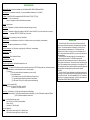
The Mini Driver MP Card is a dual rack card (it has a main [front]
module and an interface [rear] module) incorporating two short-range
modems. The card operates full-or half-duplex, in point-to-point or
multipoint applications at data rates up to 115.2 Kbps and across
distances up to 9.4 miles (15.1 km), over one or two twisted pairs. It
has 13 easy-to-read front-panel LED's so you can monitor the status of
data transmission.
The Mini Driver MP card can handle up to 50 terminal drops in a
multipoint polling environment. For RS-485 and serial-printer
applications that require hardware flow control, the Card passes one
control signal in each direction. The modems on the Card can be set for
high or low impedance and for carrier always on or controlled by RTS.
The Cards also have Silicon Avalanche Diodes for protection against the
damaging effects of nearby lightning strikes and other harmful
transients.
The Mini Driver MP card is fabricated using the latest surface-mount
technology, so you get high-quality short-range modem performance on
a convenient rack card. The card is available with RJ-11 line interface
connectors on its interface (rear) module. It fill one function-card slot in
our MicroRacks (RM202, RM204, RM208 OR RM216).
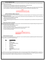
CONFIGURATION:
Setting the Configuration Jumpers and Switches:
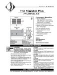
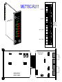
The Mini Driver MP card has two different sets of configuration controls. One set is on the main (front) module. The other set is on the interface (rear) module.
The Jumpers and Switches on the Main Module:
The Mini Driver MP card has two jumpers and four switches on its main (front) module-- a jumper and two switches for each modem as shown on the first page. With jumpers JP1 and
JP2, you can control receiver impedance. With switches S2 and S4, you can set the modems for 2-wire or 4-wire operation. With switches S1 and S3, you can control RTS/CTS
delay, echo, carrier control, and receiver squelch. JP1, S1 and S3 apply to modem Unit A; JP2, S2 and S4 apply to modem Unit B.
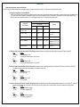
TYPICAL APPLICATIONS
Jumper and
Switch Settings
Point-to-Point
4W FDX
Multipoint
4W HDX
2W
S1-1, S3-1: RTS/CTS Dly.
S1-2, S3-2: Echo
ON
OFF
ON
ON
ON
OFF
ON
OFF
S1-3; S3-3: Carrier
OFF
ON
ON
Master: OFF
Slaves: ON
S1-4; S3-4: Rcvr Squelch
OFF
OFF
ON
OFF
JP1, JP2: Impedance
Lo-Z ( 1 & 2 )
Lo-Z ( 1 & 2 )
Lo-Z ( 1 & 2 )
Master: Lo-Z ( 1 & 2 )
Last Slave(s): Hi-Z ( 2 & 3 )
Other Slaves: Lo-Z ( 1 & 2 )
S2; S4 Wire/4-Wire
4W (Down)
4W (Down)
2W (Up)
4W (Down)
S1 Position 1 (Unit A) and S3 Position 1(Unit B): RTS/CTS Delay determines the amount of delay after the corresponding modem detects RTS before it sends CTS.
S1-1
Setting:
OFF (down)
No delay (default) for Unit A
ON (up)
8-ms delay (turn-off delay less than 1 ms.) for Unit A
S3-1
OFF (down)
ON (up)
Setting:
No delay (default) for Unit B
8-ms delay (turn-off delay less than 1 ms.) for Unit B
S1 Position 2 (Unit A) and S3 Position 2 (Unit B): Echo determines whether or not the corresponding modem will echo the data the DTE transmits on TD back to the DTE on RD.
This feature only works in 4-wire mode; nothing happens if it is activated in 2-wire mode.
S1-2
Setting:
OFF (down)
Echo off (default) for Unit A
ON (up)
Echo on for Unit A
S3-2
OFF (down)
ON (up)
Setting:
Echo off (default) for Unit B
Echo on for Unit B
S1 Position 3 (Unit A) and S3 Position 3 (Unit B): Carrier Control determines whether the carrier of the corresponding modem is always on or is controlled by RTS. "Always on"
is the factory-default setting; use the "controlled by RTS" setting when you are using the modem in a switched-carrier, multipoint, or hardware-flow-control application.
S1-3
Setting:
OFF (down)
Unit A carrier always on (default)
ON (up)
Unit A carrier controlled by RTS
S3-3
OFF (down)
ON (up)
Setting:
Unit B carrier always on (default)
Unit B carrier controlled by RTS
S1 Position 4 (Unit A) and S3 Position 4 (Unit B): Receiver Squelch determines whether the corresponding modem's receiver is always on or is squelched by RTS. If receiver
squelch is enabled and RTS is high, the receiver will be squelched and RD and CD will be held low. This feature is useful for 2-wire operation, because the receiver and
transmitter are connected to the same pair of wires. (For 4-wire operation, both switches should be set to OFF--this is the factory default).
S1-4
Setting:
OFF (down)
Receiver always on (default) for Unit A
ON (up)
Receiver squelched for Unit A
S3-4
OFF (down)
ON (up)
Setting:
Receiver always on (default) for Unit B
Receiver squelched for Unit B
S2 (Unit A) and S4 (Unit B): 2-wire/4-wire operation determines whether the corresponding modem operates in 2-wire or 4-wire mode.
S2
Setting:
4W (down)
Unit A operates in 4-wire mode (default)
2W (up)
Unit A operates in 2-wire mode
S4
4W (down)
2W (up)
Setting:
Unit B operates in 4-wire mode (default)
Unit B operates in 2-wire mode
JP1 (Unit A) and JP2 (Unit B): Receiver Impedance. Use these jumpers to get the most efficient coupling of receivers to the transmission line, and therefore the greatest distance.
For point-to-point applications, both modems are normally set to Lo-Z. For multipoint applications, set the master and the most distant one or two slaves to Lo-Z, and the rest
of the slaves to Hi-Z. (The Mini Driver MP Card's transmitter can drive signals to as many a s 50 multidrop receivers, including one or two receivers set for low
impedance).
JP1
Setting:
Lo-Z (positions 1 and 2)
Lo-Z (default) on Unit A
Hi-Z (positions 2 and 3)
Hi-Z on Unit A
JP2
Lo-Z (position 1 and 2)
Hi-Z (position 2 and 3)
Setting:
Lo-Z (default) on Unit B
Hi-Z on Unit B
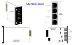
The Jumpers on the Interface Module:
The Mini Driver MP card is equipped with two RJ-11 line-interface ports and two 10-pin RJ-style serial-interface ports. Before you install the Card, you should examine the interface module you
have selected and make sure that it is configured for your application. Each interface module has five jumpers on its circuit board, as described below. The figure on the first page shows the
locations of the jumpers on the interface modules (the locations are the same for both the -RJ11 and -RJ45 models). These jumpers determine various grounding and signal characteristics for the
serial and modem-to-modem lines. The table below provides a summary of the functions of these jumpers. The functions are described in more detail afterward.
Jumper
In Positions 1 and 2
JB2
Line A Shield
JB4
Line B Shield
JB5
SGND tied to FGND
JB6
DSR A tracks DTR *
JB7
DSR B tracks DTR *
* factory-default settings
In Positions 2 and 3
No Shield *
No Shield *
SGND not tied to FGND *
N/A
N/A
Line Interface: Line A Shield and Line B Shield (JB2 and JB4)
These jumpers apply to the line interface. When one of these jumpers is in positions 1 and 2, it links RJ-11Pins 1 and 6 on the corresponding line to the interface module's frame ground. (If you are
using shielded twisted-pair cable, the shield can be connected to these pins). In positions 2 and 3, Pins 1 and 6 remain connected to each other, but are disconnected ("lifted") from frame ground.
JB2
Positions 1 and 2
Positions 2 and 3
Setting:
Line A Shield Connected
No Shield (default)
JB4
Positions 1 and 2
Positions 2 and 3
Setting:
Line B Shield Connected
No Shield (default)
CAUTION!
If you connect shield to frame ground, make sure that RJ-11 Pins 1 and 6,
as well as the cable shield, are connected to ground at one end of the cable
only. Connecting them at both ends of the cable will defeat the transformer
isolation and will leave your system open to damage from ground loops.
Serial Interface: Signal Ground and Frame Ground (JB5)
This jumper applies to the serial interface. In positions 1 and 2, this jumper links the Signal Ground (SGND) line (Pin 5) of both serial lines to the interface module's frame ground (FGND). When this
jumper is in positions 2 and 3, Pin 5 of both lines are disconnected ("lifted") from frame ground.
JB5
Positions 1 and 2
Positions 2 and 3
Setting:
SGND and FGND Connected
SGND and FGND Not Connected (default)
DSR tracks DTR (JB6 and JB7)
These jumpers MUST be left in their default positions. Because the interface module is designed to work with a whole family of products, and not just the Mini Driver MP Card, it is capable of
supporting some functions that are not used by the Mini Driver MP Card. Some products in this family might require these jumpers to be set differently, but the Mini Driver MP Card might malfunction
if either of these jumpers is in the wrong position. Make sure the jumper is placed across Pins 1 and 2. DO NOT place the jumper across Pins 2 and 3.
JB6
Positions 1 and 2
Positions 2 and 3
Setting:
DSR Tracks DTR (default)
N/A
INSTALLATION:
The MicroRacks: An Overview
Mini Driver MP Cards are designed to be installed in our MicroRacks (product codes RM202 for the 2-card models, RM204 for the 4-card models, RM208 for the 8-card models, and RM216 for the 16-card
models). You will install Mini Driver MP Cards in any MicroRack the same way.
The MicroRacks' Power Supply:
The power supply included with the MicroRacks uses the same mid-plane architecture as the line-driver cards. slide the front module of the power supply into the MicroRack from the front, and slide the rear
module in from the rear. The two modules plug into one another in the middle of the rack. Secure the front module with thumbscrews and the rear module with conventional metal screws; these screws and
thumbscrews come with the rack.
Switching the Power Supply ON and OFF:
The MicroRack's power switch is located on the power supply's front panel. When the MicroRack is plugged in and switched on, the power supply will light the red LED on its front panel. Since the
MicroRack is a "hot-swappable" rack, you don't have to install any cards before switching on the power supply. Also, the power supply may be switched off at any time without harming the installed cards,
and you can install or remove cards without turning off the power supply. However, you should always unplug the power cord before removing, replacing, or switching the power supply or its fuses.
REPLACING THE POWER SUPPLY'S FUSE:
The MicroRack's power supply uses a 400-mA fuse for 120-VAC circuits, and a 200-mA fuse for 240-VAC circuits. The fuse compartment is located just below the AC socket on the power supply's rear
module. To replace the fuse, follow these steps:
1. Making sure the rack is turned off and unplugged, use a small screw-driver to pop the compartment open: It will slide open like a drawer.
2. Notice that there are two fuses in the compartment: The rear fuse is "active," and the front fuse in the "spare".
3. If the active fuse appears to be blown, remove it from the clips and replace it with the spare from the front of the compartment. Note the size and rating of the blown fuse before discarding it.
4. Order a new replacement fuse. Both the 400-mA fuses (Littelfuse 239.400 or equivalent) and the 200-mA fuses (Littelfuse 239.200 or equivalent) measure 5 X 20 mm.
CAUTION!
For continued protection against the risk of fire, replace
blown fuses only with fuses of the same type and rating.
SWITCHING THE POWER SUPPLY BETWEEN 120 AND 240 VOLTS:
Although the MicroRack is shipped from the factory with a customer-specified power-supply configuration, you may change the configuration yourself. Follow these steps to switch the configuration of the
power supply between 120 VAC and 240 VAC:
1. Making sure the rack is turned off and unplugged, remove the power supply's front module and locate the two-position switch (labeled either "110/220" or "115/230") near the back of the card.
Slide the switch to the setting corresponding to your desired voltage.
2. Replace the existing fuses with fuses of the correct type.
3. If necessary, replace the power-supply cord with a country-specific cord. (For certain countries, your supplier might be able to give you a special quote on country-specific cords.) Plug the
cord back in.
Installing the Mini Driver MP Card in the MicroRack:
The Mini Driver MP Card is made up of a main (front) module and an interface (rear) module. The two cards meet inside the rack chassis; their mating 50-pin card-edge connectors plug into each other. Use
these steps to install each Mini Driver MP card into a MicroRack:
1. Slide the rear module into the back of the MicroRack on the metal rails.
2. Secure the rear module using the included metal screws.
3. Slide the front module into the front of the chassis. It should meet the rear module when it is almost completely in the chassis.
4. Push the front module gently into the card-edge receptacle of the rear module. It should "click" into place.
5. Secure the front module using the thumbscrews.
NOTE:
Since the MicroRack allow "hot swappable" of cards, it is not
necessary to power down the rack when you install or remove
a Mini Driver MP Card.
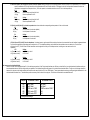
The RS-232 Serial Cables and Connectors:
The Mini Drier MP Card's RS-232 ports are always the lower two ports on its interface module. They are 10-pin female RJ-style connectors (compatible with regular male RJ-45 cable connectors), pinned
according to a modified version of the EIA/TIA-561 standard as shown below.
PIN #
SIGNAL NAME/DESCRIPTION:
1
2
3
4
5
6
7
8
9
10
Not Used
DCE Ready (DCR [DSR])
Received Line Signal Detector (RLSD [CD])
DTE Ready (DTR)
Signal Common (SCOM [SGND])
Receive Data (RD)
Transmitted Data (TD)
Clear to Send (CTS)
Request to Send (RTS)/Ready for Receiving (RR)
Not Used
The Mini Driver MP Card is wired as a DCE (Data Communications Equipment) device. Therefore, it would normally be connected to DTE (Data Terminal Equipment) RS-232 devices. You might need to run a
special cable or use a special modular adapter if the serial ports of either of the RS-232 devices you want to attach are DB25 or DB9 connectors. Even if the DTE's serial ports are RJ-45 connectors, you
might still need to use a specially pinned cable. Call Black Box Technical Support with these issues, or if you want to attach a DCE device to the card.
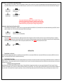
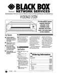
The Modem-to-Modem Line Cables and Connectors:
The Mini Driver MP Card's line ports are always the upper two ports on its interface module. They are 6-pin RJ-11 connectors, pinned for a standard telco-wiring environment, as shown below. The Mini
Driver MP Card operates full duplex over four wires (two twisted pairs). In all applications, the twisted-pair wire must be 26 AWG or thicker, unconditioned, dry, and metallic. Both shielded and unshielded
cable yield favorable results.
NOTE:
The Mini Driver MP Card can only communicate in a closed data circuit with another
Mini Driver MP Card. It will not work with dialup analog circuits, such as those used
with standard modems.
The Modem-to-modem cable connection must be specially cross-pinned. If your cabling includes punchdown blocks, you can easily do the cross-pinning at a punchdown block. If you will be running cable
directly between two Mini Driver MP Cards, you can get a custom cable from your supplier as a special quote, or you can use regular straight-through-pinned cable and repin one of the RJ connectors (that
is, rearrange the wiring connections between the terminal block and the actual contacts). You might need special crimping tools or new connectors; call Black Box for these items, or for Technical Support if
you have difficulty.
Line Cable Pinouts:
SIGNAL PIN #
GND
RCVXMT+
XMTRCV+
GND
1
2
3
4
5
6
PIN #
SIGNAL
6
4
5
2
3
1
GND
XMTRCV+
RCVXMT+
GND
123456
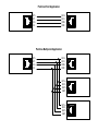
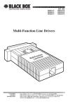
MULTIPOINT APPLICATIONS:
The Mini Driver MP Card supports multipoint applications. Maximum distance between the units will vary based on the number of drops, data rate, wire gauge, etc. Call Black Box Technical Support for
distance estimates more specific to your application. The wiring diagrams on the next page shows how to wire two-pair cables for a Mini Driver MP Card network. (We do not recommend using single-pair
cables for multipoint applications, nor do we recommend arranging multipoint equipment in a star topology.
OPERATION:
Once you have configured each Mini Driver MP Card and connected the cables, you are ready to operate the units. The Mini Driver MP Card features 13 front-panel status LED's that indicate the condition of
the modem and the communication link.
The Card will steadily light its green "PWR" LED as long as it is receiving power through its mid-plane MicroRack connection.
The green "TD" and "RD" LED's blink to show positive-state data activity. The red "TD" and "RD" LED's blink to show negative-state data activity. If the red "TD" and "RD" LED's are steadily lit, the
modem-to-modem connection for that unit is idle.
If position 1 of switch S1 and S3 on the main module is set to OFF (carrier is set to "always on"), the green "CD" LED for the corresponding modem will always be lit. If S1-1 or S3-1 on the main
module is set to ON (carrier is set to "controlled by RTS"), the Card will raise CD to the DTE and light the green "CD" LED for the corresponding modem when carrier is present, or lower CD
to the DTE and light the red "CD" LED when carrier is absent or low.
Point-to-Point Application
XMT+
XMTRCV+
RCV-
RCV+
RCVXMT+
XMT-
Point-to-Multipoint Application
XMT+
XMTRCV+
RCV-
RCV+
RCVXMT+
XMT-
RCV+
RCVXMT+
XMT-
RCV+
RCVXMT+
XMT-