1
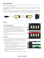
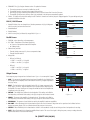
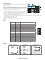
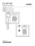
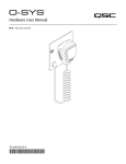
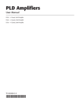
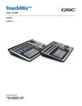
CXD-Q Amplifiers User Manual CXD4.2Q — 4 Channel, 1600 W Amplifier CXD4.3Q — 4 Channel, 2500 W Amplifier CXD4.5Q — 4 Channel, 5000 W Amplifier (DRAFT — September 17, 2014) TD-000438-00-A *TD-000438-00* 1 (DRAFT 2014/08/09) EXPLANATION OF SYMBOLS The term “WARNING!” indicates instructions regarding personal safety. If the instructions are not followed the result may be bodily injury or death. The term “CAUTION!” indicates instructions regarding possible damage to physical equipment. If these instructions are not followed, it may result in damage to the equipment that may not be covered under the warranty. The term “IMPORTANT!” indicates instructions or information that are vital to the successful completion of the procedure. The term "NOTE" is used to indicate additional useful information. The intent of the lightning flash with arrowhead symbol in a triangle is to alert the user to the presence of un-insulated "dangerous" voltage within the product's enclosure that may be of sufficient magnitude to constitute a risk of electric shock to humans. The intent of the exclamation point within an equilateral triangle is to alert the user to the presence of important safety, and operating and maintenance instructions in this manual. IMPORTANT SAFETY INSTRUCTIONS WARNING!: TO PREVENT FIRE OR ELECTRIC SHOCK, DO NOT EXPOSE THIS EQUIPMENT TO RAIN OR MOISTURE. • Keep these instructions. • Heed all warnings. • Follow all instructions. • Do not use this apparatus near water or liquids. • Do not submerge the apparatus in water or liquids. • Clean only with a dry cloth. • Do not use any aerosol spray, cleaner, disinfectant or fumigant on, near or into the apparatus. • Do not block any ventilation opening. Install in accordance with the manufacturer's instructions. • Keep ventilation opening free of dust or other matter. • Do not install near any heat sources such as radiators, heat registers, stoves, or other apparatus (including amplifiers) that produce heat. • Do not defeat the safety purpose of the polarized or grounding-type plug. A polarized plug has two blades with one wider than the other. A grounding type plug has two blades and a third grounding prong. The wide blade or the third prong are provided for your safety. If the provided plug does not fit into your outlet, consult an electrician for replacement of the obsolete outlet. • Protect the power cord from being walked on or pinched particularly at plugs, convenience receptacles, and the point where they exit from the apparatus. • Only use attachments/accessories specified by the manufacturer. • Unplug this apparatus during lightning storms or when unused for long periods of time. • Inspect the apparatus for signs of external wear and tear or signs of damage. All damage to the apparatus should be immediately repaired by a QSC authorized service station or QSC International Distributor. Failure to perform necessary repairs could lead to additional damage or to safety hazards. Failure to perform necessary repairs voids the limited warranty and QSC is not responsible for any injury, harm or related damages arising from any failure to perform those repairs. • Refer all servicing to qualified service personnel. Servicing is required when the apparatus has been damaged in any way, such as power-supply cord or plug is damaged, liquid has been spilled or objects have fallen into the apparatus, the apparatus has been exposed to rain or moisture, does not operate normally, or has been dropped. • The appliance coupler, or the AC Mains plug, is the AC mains disconnect device and shall remain readily operable after installation. • Adhere to all applicable, local codes. • Consult a licensed, professional engineer when any doubt or questions arise regarding a physical equipment installation. 2 (DRAFT 2014/08/09) FCC Statement For CXD-Q 4.3 and CXD-Q 4.5 NOTE: This equipment has been tested and found to comply with the limits for a Class A digital device, pursuant to Part 15 of the FCC Rules. These limits are designed to provide reasonable protection against harmful interference when the equipment is operated in a commercial environment. This equipment generates, uses, and can radiate radio frequency energy and, if not installed and used in accordance with the instruction manual, may cause harmful interference to radio communications. Operation of this equipment in a residential area is likely to cause harmful interference in which case the user will be required to correct the interference at his own expense. For CXD-Q 4.2 NOTE: This equipment has been tested and found to comply with the limits for a Class B digital device, pursuant to Part 15 of the FCC Rules. These limits are designed to provide reasonable protection against harmful interference in a residential installation. This equipment generates, uses and can radiate radio frequency energy and, if not installed and used in accordance with the instructions, may cause harmful interference to radio communications. However, there is no guarantee that interference will not occur in a particular installation. If this equipment does cause harmful interference to radio or television reception, which can be determined by turning the equipment off and on, the user is encouraged to try to correct the interference by one or more of the following measures: • • • • Reorient or relocate the receiving antenna. Increase the separation between the equipment and receiver. Connect the equipment into an outlet on a circuit different from that to which the receiver is connected. Consult the dealer or an experienced radio/TV technician for help. RoHS STATEMENT The QSC CXD4.2Q , CXD4.3Q , and CXD4.5Q amplifiers are in compliance with European Directive 2002/95/EC – Restriction of Hazardous Substances (RoHS). The QSC CXD4.2Q , CXD4.3Q , and CXD4.5Q amplifiers are in compliance with “China RoHS” directives. The following chart is provided for product use in China and its territories: QSC CXD4.2Q , CXD4.3Q , and CXD4.5Q Amplifiers 部件名称 (Part Name) 有毒有害物质或元素 (Toxic or hazardous Substances and Elements) 铅 (Pb) 汞 (Hg) 镉 (Cd) 六价铬 (Cr(vi)) 多溴联苯 (PBB) 多溴二苯醚 (PBDE) 电路板组件 (PCB Assemblies) X O O O O O 机壳装配件 (Chassis Assemblies) X O O O O O O: 表明这些有毒或有害物质在部件使用的同类材料中的含量是在 SJ/T11363_2006 极限的要求之下。 (O: Indicates that this toxic or hazardous substance contained in all of the homogeneous materials for this part is below the limit requirement in SJ/T11363_2006.) X: 表明这些有毒或有害物质在部件使用的同类材料中至少有一种含量是在 SJ/T11363_2006 极限的要求之上。 (X: Indicates that this toxic or hazardous substance contained in at least one of the homogeneous materials used for this part is above the limit requirement in SJ/T11363_2006.) Warranty For a copy of the QSC Limited Warranty, visit the QSC Audio Products website at www.qsc.com Para una copia de la Garantía Limitada de QSC, visite el sitio web de QSC Audio Products, en www.qsc.com Pour obtenir une copie de la garantie limitée de QSC, visitez le site de QSC Audio Products à www.qsc.com Besuchen Sie die Webseite von QSC Audio Products (www.qsc.com) um eine Kopie der beschräenkte Garantie von QSC zu erhalten. 如果想要QSC 有限保修的複印本,造QSC 音品的网站www.qsc.com 3 (DRAFT 2014/08/09) Rack-Mount the Amplifier 1. Secure the amplifier in the rack with eight screws (not supplied), four in front, four in back. — Figure 1 — Unpacking There are no special unpacking instructions. You may want to keep the shipping material for the unlikely event that the amplifier should need returning for service. Package Contents 1. Quick-Start Guide TD-000350-00 5. Euro-style Connector Plug, 3-pin (4) 2. Warning Information Sheet TD-000420-00 6. Euro-style Connector Plug, 8-pin (1) 3. CXD-Q Amplifier 7. Euro-style Connector Plug, 3.5 mm, 2-pin (1) 4. IEC AC Power Cord 8. Euro-style Connector Plug, 3.5 mm, 3-pin (1) 4 (DRAFT 2014/08/09) Features Amplifier Front Panel 1 A CXDQ 2 3 4 5 6 7 8 9 10 11 MUTE B OUTPUT MUTE NETWORK AMPLIFIER C MUTE 12 D NEXT MUTE GAIN 13 LIM -10 PREV 14 15 ID 16 17 -20 SEL SEL SEL SEL CLIP SIG 2 INPUT 3 1 FAULT 4 — Figure 2 — 1. Output channels are labeled A, B, C, and D 10. Input Channel Signal-Present LEDs (Blue) 2. Output Channel Mute Buttons and LEDs (Red) 11. Input channels are labeled 1, 2, 3, and 4 3. Output Channel Limiter LEDs (Red) 12. LCD Graphic Display 4. Output Channel -10 dB below maximum amplifier output (Blue) 13. NEXT Button 5. Output Channel -20 dB below maximum amplifier output (Blue) 14. PREV Button 6. Soft Power Button (Green/Red) 15. MASTER CONTROL Knob 7. Channel Select Buttons and LEDs (Blue for Output) 16. ID Button 8. Input Channel Clip LEDs (Red) 17. Pinhole Reset 9. FAULT LED Amplifier Rear Panel NOTE: The CXD4.3Q , and CXD4.5Q models have a different rear panel configuration than the CXD4.2Q amplifier. The difference is that the position of the fan and the eight-pin Euro-style connector and associated information are interchanged. 1 2 LAN A LAN B 3 ROUTABLE INPUTS 1 2 4 3 4 + + CH B + CH C + CH D CH A 1 2 3 4 5 6 7 8 9 10 11 12 13 14 15 16 5 CH AB T1+ T2T3+ T4- T1 T2 CH CD T5+ T6T7+ T8- T3 T4 T5 CH A+B T1+ T3- T6 CH C+D T5+ T7- T7 T8 CH AB+CD T1+ T5T3+ T7- CH ABC T1+ T2T3+ T4T5+ T6CH ABCD T1+ T2T3+ T4T5+ T6T7+ T8- — Figure 3 — 1. RJ-45 Q-Sys Q-LAN A/B 6. AC Power Switch 2. GPIO Euro-style Connector, 16-pin 7. Locking IEC Power Connection 3. Inputs - Four three-pin Euro-style Connectors 8. Rear Rack-mount Bracket 4. One eight-pin Euro-style Loudspeaker Connector 9. Front Rack-mount Brackets 5. Cooling fan 5 (DRAFT 2014/08/09) 6 7 8 9 Connections LAN A LAN B Q-Sys Q-LAN Connect the amplifier LAN A, and if available, LAN B, to the Q-LAN network. (Figure 4) Refer to your Q-Sys documentation for network requirements and connection detail. — Figure 4 — Unbalanced Balanced Inputs The analog inputs are converted to digital audio in the CXD-Q amplifiers and then routed to the Q-Sys Core over the network. The digital signals show up in Q-Sys Designer at the CXD-Q input component where they can be routed as needed. Refer to the Q-Sys documentation. — 1. Wire the audio mic- or line-level source to up to four Euro-style connectors (supplied). You may use either balanced inputs (Figure 5) or unbalanced inputs (Figure 6). Adjust input sensitivity in Q-Sys Designer. 2. Plug the connectors into the appropriate receptacles (Routable Inputs 1, 2, 3, 4) Figure 7. + + — — Figure 6 — — Figure 5 — ROUTABLE INPUTS 1 2 3 4 WARNING!: Do not turn the amplifier on at this time. 3. Connect the IEC power cord to the AC receptacle on the rear of the amplifier. (Figure 8) — Figure 7 — GPIO Figure 9 shows the GPIO connector, refer to "GPIO" on page 11 for details about using the GPIO. 1 2 3 4 5 6 7 8 Outputs and Configuration The configuration of the amplifier and the amplifier component in the Q-Sys design file must match. Double check that these are identical and if necessary change the configuration by following the instructions on the front panel of the amplifier. When the output configuration of the amplifier changes, the Outputs to the loudspeakers change accordingly. Use the diagrams shown in Figure 10 thru Figure 12 as a reference for wiring the loudspeakers. — Figure 8 — 9 10 11 12 13 14 15 16 — Figure 9 — CAUTION!: Before turning the amplifier on, double check your output connections to be sure they are connected properly based on the output configuration specified in Q-Sys Designer. After connecting the outputs to the loudspeakers, you may turn the amplifier on. Figure 10 through Figure 13 are examples of the three types of output configurations: Separate, Bridged and Parallel. The tables to the right of the loudspeaker connections give all the possible configurations and their connections. Separate Channels (A B C D) OUTPUTS TO SPEAKERS For Four Separate Loudspeakers Use four 2-wire cables, connect to: • T1+/T2- (Loudspeaker 1) • T3+/T4- (Loudspeaker 2) • T5+/T6- (Loudspeaker 3) • T7+/T8- (Loudspeaker 4) + + CH B + CH C + CH D CH A CHANNEL CONFIGURATION Q A Q B Q C Q D 4 Channels: A B C D Channel Configuration Locked to Design — Figure 10 — 6 (DRAFT 2014/08/09) T1 T2 T3 T4 T5 T6 T7 T8 PARALLEL CHANNEL COMBINING APPLICATIONS CH AB T1+ T2SETTINGS CAN BE T3 + T4CONFIGURED FOR 70V, 100V AND 200V DIRECT OUTPUT. BRIDGED CH A+B T1+ T3- CH C+D T5+ T7CH AB+CD T1+ T5T3+ T7- CH CD T5+ T6T7+ T8CH ABC T1+ T2T3+ T4T5+ T6CH ABCD T1+ T2T3+ T4T5+ T6T7+ T8- Bridged (A+B) and Separate (C D) Channels For A+B (Bridged) One Loudspeaker OUTPUTS TO SPEAKERS Use one 2-wire cable connect to: • T1+/T3- + + CH B + CH C + CH D CH A For C & D (Separate) Two Loudspeakers Use two 2-wire cables connect to: • T5+/T6- for CH C • T7+/T8- for CH D CHANNEL CONFIGURATION Q A+B Q C Q D T1 T2 T3 PARALLEL CHANNEL COMBINING APPLICATIONS CH AB SETTINGS CAN BE T1+ T2CONFIGURED FOR T3 + T470V, 100V AND 200V DIRECT OUTPUT. BRIDGED T4 CH A+B T1+ T3- T5 CH C+D T5+ T7- T6 CH AB+CD T1+ T5T3+ T7- T7 T8 CH CD T5+ T6T7+ T8CH ABC T1+ T2T3+ T4T5+ T6CH ABCD T1+ T2T3+ T4T5+ T6T7+ T8- 3 Channels: A+B C D Channel Configuration Locked to Design — Figure 11 — Parallel Channels (ABCD) For One Loudspeaker OUTPUTS TO SPEAKERS Full power to one loudspeaker Use one 2-wire cable, connect to: • T1+/T2• Jumper T1, T3, T5, T7 • Jumper T2, T4, T6, T8 + + CH B + CH C + CH D CH A For Multiple Loudspeakers Full power for multiple loudspeakers in parallel Use up to four 2-wire cables, connect to: • T1+/T2CHANNEL CONFIGURATION • T3+/T4• T5+/T6Q ABCD • T7+/T81 Channel: A B C D Channel Configuration Locked to Design T1 T2 T3 SETTINGS CAN BE CONFIGURED FOR 70V, 100V AND 200V DIRECT OUTPUT. T4 T5 T6 T7 T8 T1+, T3+, T5+, and T7+ are electrically the same point T2-, T4-, T6-, and T8- are electrically the same point — Figure 12 — Connect the Loudspeakers 1. Connect the loudspeaker wiring to the 8-pin Euro-style connector as needed for your amplifier's configuration. 2. Install the female 8-pin Euro-style connector onto the male connector on the rear of the amplifier as shown in Figure 13. 3. Use a Phillips screwdriver to secure the connector. — Figure 13 — 7 (DRAFT 2014/08/09) BRIDGED CH A+B T1+ T3- CH C+D T5+ T7CH AB+CD T1+ T5T3+ T7- PARALLEL CHANNEL COMBINING APPLICATIONS CH AB T1+ T2T3+ T4CH CD T5+ T6T7+ T8CH ABC T1+ T2T3+ T4T5+ T6CH ABCD T1+ T2T3+ T4T5+ T6T7+ T8- Amplifier Control NOTE: The following scenarios assume that the amplifier is connected to the Q-Sys Core via Q-LAN. When the amplifier is not connected to the Q-Sys Core, it is in a Fault mode, and not operational. NEXT & PREV Buttons • Rear power switch is off, the amplifier is not operable. The power switch is the AC Mains disconnect. • The power button is not illuminated. PREV • Navigates forward and backwards through the screens. ID Button Off Mode NEXT ID • Press this button to display a screen with the amplifier's network name. In addition, the ID buttons on the associated Q-Sys Amplifier component and the associated Q-Sys Configurator item flashes. Press again, or click one of the other ID buttons, to stop the flashing and exit the screen. • Turn the power switch to on. The amplifier enters the mode in which it was when power was removed – Run, Mute All, or Standby. • When prompted, press this button to change the amplifier configuration to match the configuration of the associated Q-Sys design. Run Mode SEL Buttons • From Standby or Mute All mode, press and release the power button on the front panel. The amplifier is in Run Mode. • Use these buttons to select an output channel in order to change the Gain. • The power button is illuminated green. • Select more than one channel to change multiple gain settings at the same time. • The amplifier is fully operable; audio can pass. SEL • If two or more outputs are bridged or in parallel, pressing one button in the group selects all channels in that bridged or parallel group. Standby Mode • From Mute All or Run mode, press and hold the power button on the front panel for approximately four seconds. • The power button illuminates solid red. • The amplifier is not operable; audio will not pass. Mute Buttons MUTE • Use these buttons to mute the audio of the associated output channel. • When the output configuration is changed, the Mute buttons are engaged automatically. You must manually unmute the channels. Mute All Mode • From the Run Mode, quickly press and release the power button. • The power button flashes red, all output Mute buttons are red. • The amplifier output is disabled, but the front panel is fully operable. Master Control Knob • When a new design is sent to the amplifier from Q-Sys, the outputs are muted while the amplifier is offline. Pinhole Reset • Insert a paper clip or similar tool into the pinhole then press and hold for 5 seconds to reset the amplifier to the factory default settings. The default settings include network settings, and amplifier name. • Adjusts the Gain for the selected channel or channels. At least one channel must be selected. • When one or more channels are selected, turn the Master Control knob to jump to the Gain screen. After a few seconds with no activity, it returns to the earlier screen. • If there is more than one channel selected, and the gains for those channels are different, the difference is maintained unless the gain is raised or lowered to the limits for both channels. 8 (DRAFT 2014/08/09) Inputs and Outputs The CXD-Q amplifiers have four Mic/Line Inputs and four amplified Outputs on the rear of the amplifier. The Inputs and Outputs on the rear of the amplifier are not connected inside the amplifier. The analog inputs are converted to digital audio in the CXD-Q amplifiers and then routed to the Q-Sys Core via Q-LAN (LAN A, LAN B). The digital signals are brought into the design in the CXD-Q Amplifier Input component. From the CXD-Q Input component the signals can be sent anywhere within the system. Likewise, in Q-Sys Designer digital signals are received at the CXD-Q Output component and fed from the Q-Sys Core to the analog amplified outputs of the CXD-Q via Q-LAN. The CXD-Q output component can have one to four outputs depending on the configuration of the amplifier. The desired configuration is selected in the properties menu for that amplifier. Use the ID button on the front panel of the amplifier to accept the configuration. + + CH B + CH C + CH D - T1 CH A ROUTABLE INPUTS 1 2 3 4 Q-LAN CXD4.3Q In cxq-1234 Q-Sys DSP, Routing, and so on. CXD4.3Q Out cxq-1234 Q-LAN CXD-Q Output Component CXD-Q Input Component T2 T3 T4 T5 T6 T7 T8 — Figure 14 — Screens CHANNEL CONFIGURATION Channel Configuration Screens 1. Graphic representations of the amplifier's output configuration. Inputs (Q) are from Q-Sys, 1 outputs (A-D) show the amplifier channels and their configuration. 2. Text indicating how many channels, and the output configuration. For possible configurations refer to the Q-Sys help for the CXD-Q Amplifier component. Q A 2 3 Q B Q C Q D 4 Channels: A B C D Channel Configuration Locked to Design 3. Status of the amplifier and Q-Sys design indicating the design and amp are in sync. 4. Status of the amplifier indicating that action is necessary to synchronize the design and amplifier. CHANNEL CONFIGURATION 4 5. Action you need to perform to change the amplifier configuration. Press the ID button to the right of the message. Design requires 3 Channels: A+B C D Q A Q B Q C Q D 4 Channels: A B C D Status Screen 5 Press ID to Accept 1. DEVICE: This is the hostname (network name) of the amplifier. A default name is given at the factory, similar to the example. You may change the name in the Q-Sys Configurator. — Figure 15 — 2. DESIGN: This is the name of the Q-Sys design containing the amplifier. The amplifier must be in a running design to operate. 3. STATUS: Displays the current status of the amplifier both in text and color. The following is 1 2 a list of possible status colors, and some example conditions. • OK – Green – Audio is good, hardware is good. • Compromised – Orange – Audio is good but a redundancy mechanism is active (one LAN down but the other is still up) or a non-fatal hardware problem exists (fans too slow, temperature higher than expected, etc.) • Fault – Red – Audio is not passing, or hardware is malfunctioning or mis-configured (amplifier power off, audio streams broken, amplifier fault, loudspeaker short circuit, etc.) • Initializing – Blue – In the process of initialization, and design start. Audio is not passed. 9 (DRAFT 2014/08/09) DEVICE: STATUS CXQ-1234 DESIGN: My Design Filename 3 STATUS: 4 FIRMWARE: 5 OK 4.0.00 GAIN AB: -27.0 dB 6 — Figure 16 — GAIN C: 0 dB GAIN D: 10.0 dB 4. FIRMWARE: The Q-Sys Designer firmware version. To update the firmware: a. The version you want to use must be installed on your PC, b. The amplifier must be connected to the network, and turned on. c. Open the Q-Sys design containing the amplifier and select "Save to Core and Run" from the File menu. d. The amplifier Q-LAN processor and any other Q-Sys peripherals in the design are automatically updated. 5. GAIN A - D: Displays the current Gain setting for each channel. If channels are combined, they are displayed together. The green background gives a graphical indication of the Gain. LAN A LAN A / LAN B Screen 1. Default IP Address. You can change this and the other parameters in Q-Sys Configurator. LAN A is required, and cannot be turned off. 2. Default Netmask. 1 2 3 IP ADDRESS: 192.168.xxx.xxx NETMASK: 255.255.0.0 GATEWAY: 0.0.0.0 4 LAN B IP ADDRESS: 3. Default Gateway. NETMASK: 4. LAN B is not required, as indicated by empty fields in Figure 17. GATEWAY: — Figure 17 — Health Screen 1. FAN RPM – varies depending on the temperature. 2. PSU TEMP – Temperature of the Power Supply Unit. • 55º C causes a compromised state for the amplifier. • 63º C Mutes Audio 3. Channels A&C, and B&D. • Thermal Limiting starts at 69º C, shows a compromised state • Thermal Shutdown at 80º C HEALTH 1 FAN RPM: 1109 2 PSU TEMP: 35.3°C A&C Temp: 35.4°C B&D Temp: 35.3°C 3 4 VRAIL 1: 149 VRAIL 2: -151 4. Voltage Rails — Figure 18 — • CXD4.3Q & CXD4.5Q » VRail 1 = +147 VDC +/- 5 V typical » VRail 2 = -147 VDC +/- 5 V typical • CXD4.2Q » VRail 1 = +85 VDC +/- 5 V typical » VRail 2 = -85 VDC +/- 5 V typical Output Screens OUTPUT A Each output or group of outputs has a dedicated screen. Figure 19 is an example of Output A. 1. GAIN – The amount of gain applied to the input signal. Controlled by the GAIN knob on the front panel of the amplifier, or the GAIN control in the CXD-Q Output component in the Q-Sys Design. 2. INPUT – The level of the audio signal applied to the CXD-Q Output component in the Q-Sys design. The CXD-Q Output component is the connection to the output section of the amplifier. This meter reading can be changed from RMS to Peak in the Amplifier Out component in the Q-Sys design. 1 GAIN: -23.0 dB 2 Q-LAN INPUT: -45.0 dB 3 VOLTAGE: .777 V 4 POWER: .011 W 5 HEADROOM: 3. VOLTAGE - The voltage being delivered to the loudspeaker. This reading can be RMS or Peak depending on the Meter Select setting in the Q-Sys design for the associated channel. -41.3 dB DAC LIMIT PROTECT CLIP LIMIT 6 7 8 9 — Figure 19 — 4. POWER – The power of the amplifier / loudspeaker circuit. This reading can be RMS or Peak depending on the Meter Select setting in the Q-Sys design for the associated channel. 5. HEADROOM – The amount of room left before reaching the amplifier's maximum capabilities. 6. DAC LIMIT – When illuminated, this indicates that the signal to the D to A Converter is larger than can be reproduced and a limiter has been engaged to prevent clipping. This is an indication that the gain structure is not correct. 7. PROTECT – When illuminated, this indicates that the channel is in Protect Mode. Usually due to driving too low of an impedance for too long. 8. LIMIT – When illuminated, this indicates the amplifier limiter is active. This occurs if the signal is driving the power, current, or voltage above the amplifier rated values or due to thermal limiting. 10 (DRAFT 2014/08/09) 1 Output Gains Screen 2 The Output Gains screen provides a quick overview of all outputs and is the screen on which GAIN adjustments are made. Use the NEXT or PREV buttons to access this screen or, press one or more of the SEL buttons to access the screen and make GAIN adjustments for the selected channels. If you press one or more of the SEL buttons, and do not make any GAIN adjustments, this screen remains visible for a short time the returns to the previous screen. 3 OUTPUT GAINS AB -45.0 dB -8.08 dB VOLTS: 101 V 4 5 6 C -45.0 dB 1. The highlighted background indicates that the Channel is selected by the SEL button. D 2. Channel – the channels display according to the configuration of the amplifier. Q-LAN: -45.0 dB 3. Output Gain – the output gain is controlled by the GAIN knob on the amplifier or with the Gain control in the CXD-Q Output component in the Q-Sys design. Q-LAN: -100.0 dB VOLTS: .014 V Q-LAN: -100 dB VOLTS: .014 V — Figure 20 — 4. Q-LAN Input Level – the level of the audio signal applied to the CXD-Q Output component in the Q-Sys design. The CXD-Q Output component is the connection to the output section of the amplifier. 5. Voltage – The voltage applied to that output. 6. Output B is combined with Output A, the slot for Output B is removed. GPIO Connector Pin Examples GPIO # and Function Specifications 1 3.3 V 100 mA max (power cycle to reset current limiting) 2 GPIO 1 5mA in/out, 3.3V max, 127 Ohm resistor in series 3 GPIO 2 5mA in/out, 3.3V max, 127 Ohm resistor in series 4 GND Ground 5 GPIO 3 5mA in/out, 3.3V max, 127 Ohm resistor in series 6 GPIO 4 5mA in/out, 3.3V max, 127 Ohm resistor in series 7 GND Ground 8 GPIO 5 18mA in/out max, 3.3V max, 127 Ohm resistor in series 9 RELAY NO Relay Normally Open 10 RELAY COM Relay Common 11 RELAY NC Relay Normally Closed 12 GND Ground 13 GPIO 6 18mA in/out max, 3.3V max, 127 Ohm resistor in series 14 GPIO 7 18mA in/out max, 3.3V max, 127 Ohm resistor in series 15 GND Ground 16 GPIO 8 18mA in/out max, 3.3V max, 127 Ohm resistor in series Button or Contact Closure GPIO Ground Q-Sys-Powered LED GPIO 5-8 +3.3 V Ground — Figure 22 — 11 (DRAFT 2014/08/09) 9 10 11 12 13 14 15 16 — Figure 21 — Potentiometer GPIO Analog In 1 2 3 4 5 6 7 8 10 kΩ Ground Works for LEDs up to 18 mA. Current is limited in the GPIO circuit by a 127 resister in series. Specifications CXD-Q 4.2 CXD-Q 4.3 CXD-Q 4.5 4 Channel 100 Vrms 70 Vrms 8 4 2 Burst N/A N/A 500 Watts 700 Watts 600 Watts Continuous N/A N/A 400 Watts 400 Watts 325 Watts Burst N/A N/A 900 Watts 1400 Watts 1200 Watts Continuous 500 625 625 Watts 625 Watts 625 Watts Burst N/A N/A 1200 Watts 2000 Watts 1600 Watts Continuous 1000 1250 1150 Watts 1250 Watts 625 Watts 2 Channel 8 4 2 Burst 1200 Watts 1500 Watts 1500 Watts Continuous 800 Watts 800 Watts 650 Watts Burst 2400 Watts 2000 Watts 2500 Watts Continuous 1250 Watts 1250 Watts 1250 Watts Burst 4000 Watts 2400 Watts 4000 Watts Continuous 2250 Watts 2250 Watts 2100 Watts 1 Channel 8 4 2 1 Burst 1600 Watts 2500 Watts 1700 Watts 2500 Watts Continuous 1500 Watts 1600 Watts 1600 Watts 1600 Watts Burst 3500 Watts 5000 Watts 3500 Watts 5000 Watts Continuous 2500 Watts 2500 Watts 2500 Watts 2500 Watts Burst 4500 Watts 7500 Watts 4500 Watts 7500 Watts Continuous 4200 Watts 4200 Watts 4250 Watts 3700 Watts Typical Distortion 8 4 0.01 - 0.03% 0.03 - 0.06% 0.01 - 0.03% 0.03 - 0.06% 0.01 - 0.03% 0.03 - 0.06% Maximum Distortion 4 - 8 1.0% 1.0% 1.0% Frequency response (8) 20 Hz - 15 kHz +/- 0.2 dB 20 Hz - 20 kHz +0.2 dB / -0.7 dB 20 Hz - 15 kHz +/- 0.2 dB 20 Hz - 20 kHz +0.2 dB / -0.7 dB 20 Hz - 15 kHz +/- 0.2 dB 20 Hz - 20 kHz +0.2 dB / -0.7 dB -101 dB -109 dB -101 dB -109 dB -101 dB -109 dB Gain (1.2 V setting) 34.0 dB 38.4 dB 38.4 dB Damping factor >150 >150 >150 Input impedance >10 k, balanced or unbalanced >10 k, balanced or unbalanced >10 k, balanced or unbalanced Maximum input level (3.9 V setting) (1.2 V setting) 12.28 V (+24 dBu) 3.88 V (+14 dBu) 12.28 V (+24 dBu) 3.88 V (+14 dBu) 12.28 V (+24 dBu) 3.88 V (+14 dBu) Noise Unweighted Output Unmuted Weighted Output Muted Controls and indicators (front) Power • Channel MUTE Buttons • Channel SELECT Buttons • Channel Input Signal and CLIP LED Indicators • Channel Output and LIMIT LED Meters • NEXT, PREV, ID Buttons • Control Knob • FAULT LED • Pinhole Reset Controls and indicators (rear) AC Power Disconnect Input connectors Line Input GPI Input 3-pin Euro-style 2-pin Euro-style 3.5 mm Output connectors Loudspeaker Output GPIO Output 8-pin Euro-style 3-pin Euro-style 3.5 mm Amplifier and load protection Short circuit, open circuit, thermal, RF protection. On/Off muting, DC fault shutdown, active inrush limiting AC Power Input Universal Power Supply 100 - 240 VAC, 50 - 60 Hz Dimensions (HWD) 3.5” x 19” x 12” (89 x 482 x 305 mm) 3.5” x 19” x 16” (89 x 482 x 406 mm) 3.5” x 19” x 16” (89 x 482 mm x 406 mm) Weight, Net / Shipping 18.5 lb (8.4 kg) / 22 lb (10.0 kg) 21.0 lb (9.5 kg) / 25 lb (11.3 kg) 22.0 lb (10.0 kg) / 26 lb (11.8 kg) Burst Power – 20 ms 1 kHz sine burst, all channels driven Continuous Power – EIA 1 kHz 1% THD, all channels driven 12 (DRAFT 2014/08/09) Heat Loss Charts Heat losses are the thermal emissions from an amplifier while it is operating. It comes from dissipated waste power—i.e., real AC power in minus audio power out. Measurements are provided for various loads at idle, 1/8 of average full power, 1/3 of average full power, and full power, with all channels driven simultaneously. For typical usage, use the idle and 1/8 power figures. This data is measured from representative samples; due to production tolerances, actual heat emissions may vary slightly from one unit to another. Bridged mono into 8 ohms is equivalent to 4 ohms per channel; into 4 ohms is equivalent to 2 ohms per channel. BTU/hr kcal/hr 180 46 Idle CXD-Q 4.2 CXD-Q 4.3 225 57 CXD-Q 4.5 286 72 Load per Channel 8Ω 4Ω BTU/hr 2Ω BTU/hr kcal/hr kcal/hr CXD-Q 4.2 432 109 476 120 CXD-Q 4.3 684 172 794 200 CXD-Q 4.5 811 204 1144 288 BTU/hr 25V-70V-100V kcal/hr BTU/hr kcal/hr 597 150 nr nr 1040 262 nr nr 1124 283 nr nr 1/8th Power 1/3rd Power CXD-Q 4.2 849 214 873 220 1215 306 nr nr CXD-Q 4.3 983 248 1261 318 1869 471 nr nr CXD-Q 4.5 881 222 1708 430 1737 438 nr nr Full Power CXD-Q 4.2 1352 341 1478 372 2120 534 nr nr CXD-Q 4.3 2498 629 2925 737 4198 1058 nr nr CXD-Q 4.5 3116 785 5318 1340 4208 1060 nr nr Idle Thermal loss at idle or with very low signal level. 1/8 Power Thermal loss at 1/8 of full power is measured with pink noise. It approximates operating with music or voice with light clipping and represents the amplifier's typical "clean" maximum level, without audible clipping. Use these figures for typical maximum level operation. 1/3 Power Thermal loss at 1/3 of full power is measured with pink noise. It approximates operating with music or voice with very heavy clipping and a very compressed dynamic range. Full Power Thermal loss at full power is measured with a 1 kHz sine wave. However, it does not represent any real-world operating condition. 13 (DRAFT 2014/08/09) Mailing Address: QSC Audio Products, LLC 1675 MacArthur Boulevard Costa Mesa, CA 92626-1468 USA Telephone Numbers: Main Number: (714) 754-6175 Sales & Marketing: (714) 957-7100 or toll free (USA only) (800) 854-4079 Customer Service: (714) 957-7150 or toll free (USA only) (800) 772-2834 Facsimile Numbers: Sales & Marketing FAX: (714) 754-6174 Customer Service FAX: (714) 754-6173 World Wide Web: www.qsc.com E-mail: [email protected] [email protected] [email protected] © 2014 QSC Audio Products, LLC. All rights reserved. QSC and the QSC logo are registered trademarks of QSC Audio Products, LLC in the U.S. Patent and Trademark office and other countries. All other trademarks are the property of their respective owners. http://patents.qsc.com. 14 (DRAFT 2014/08/09)