1
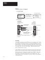
Data Highway or Data Highway Plus
Asynchronous (RS-232-C or RS-422-A)
Interface Module
Cat. No. 1770-KF2)
User Manual
Important User Information
Because of the variety of uses for the products described in this publication,
those responsible for the application and use of this control equipment must
satisfy themselves that all necessary steps have been taken to assure that each
application and use meets all performance and safety requirements, including
any applicable laws, regulations, codes and standards.
The illustrations, charts, sample programs and layout examples shown in this
guide are intended solely for purposes of example. Since there are many
variables and requirements associated with any particular installation, the
Allen-Bradley Company, Inc. does not assume responsibility or liability (to
include intellectual property liability) for actual use based upon the examples
shown in this publication.
Allen-Bradley Publication SGI-1.1, “Safety Guidelines for the Application,
Installation and Maintenance of Solid State Control” (available from your local
Allen-Bradley office) describes some important differences between solid-state
equipment and electromechanical devices which should be taken into
consideration when applying products such as those described in this
publication.
Reproduction of the contents of this copyrighted manual, in whole or in part,
without written permission of the Allen-Bradley Company Inc. is prohibited.
Throughout this manual we use notes to make you aware of safety
considerations:
ATTENTION: Identifies information about practices or
circumstances that can lead to personal injury or death, property
damage or economic loss.
Attentions help you:
identify a hazard
avoid the hazard
recognize the consequences
Important: Identifies information that is especially important for
successful application and understanding of the product.
Interchange, ControlView, Data Highway Plus and DH+ are trademarks and PLC is a registered
trademark of Allen-Bradley Company, Inc.
HART is a registered trademark of Rosemount Inc.
IBM is a registered trademark of International Business Machines Corporation.
Table of Contents
Introduction . . . . . . . . . . . . . . . . . . . . . . . . . . . . . . . . . . . .
11
General . . . . . . . . . . . . . . . . . . . . . . . . . . . . . . . . . . . . . . . . . . .
About This Manual . . . . . . . . . . . . . . . . . . . . . . . . . . . . . . . . . . .
Module Description . . . . . . . . . . . . . . . . . . . . . . . . . . . . . . . . . .
Specifications . . . . . . . . . . . . . . . . . . . . . . . . . . . . . . . . . . . . . .
Data Highway Applications . . . . . . . . . . . . . . . . . . . . . . . . . . . . .
PCL Applications . . . . . . . . . . . . . . . . . . . . . . . . . . . . . . . . . . . .
11
11
13
14
15
17
Communication Concepts . . . . . . . . . . . . . . . . . . . . . . . . .
21
General . . . . . . . . . . . . . . . . . . . . . . . . . . . . . . . . . . . . . . . . . . .
Physical Link Layer . . . . . . . . . . . . . . . . . . . . . . . . . . . . . . . . . .
Software Layers . . . . . . . . . . . . . . . . . . . . . . . . . . . . . . . . . . . . .
21
22
28
Installation . . . . . . . . . . . . . . . . . . . . . . . . . . . . . . . . . . . . .
31
General . . . . . . . . . . . . . . . . . . . . . . . . . . . . . . . . . . . . . . . . . . .
Communication Option Switches . . . . . . . . . . . . . . . . . . . . . . . . .
Mounting (Placing) . . . . . . . . . . . . . . . . . . . . . . . . . . . . . . . . . . .
Interface Connections . . . . . . . . . . . . . . . . . . . . . . . . . . . . . . . . .
Diagnostic Indicators . . . . . . . . . . . . . . . . . . . . . . . . . . . . . . . . .
31
31
38
39
318
Asynchronous Link Protocols . . . . . . . . . . . . . . . . . . . . . .
41
General . . . . . . . . . . . . . . . . . . . . . . . . . . . . . . . . . . . . . . . . . . .
Definition of Link Protocol . . . . . . . . . . . . . . . . . . . . . . . . . . . . . .
FullDuplex Protocol . . . . . . . . . . . . . . . . . . . . . . . . . . . . . . . . . .
HalfDuplex Protocol . . . . . . . . . . . . . . . . . . . . . . . . . . . . . . . . .
41
41
42
421
Message Packet Formats . . . . . . . . . . . . . . . . . . . . . . . . . .
51
General . . . . . . . . . . . . . . . . . . . . . . . . . . . . . . . . . . . . . . . . . . .
Application Layer . . . . . . . . . . . . . . . . . . . . . . . . . . . . . . . . . . . .
Network Layer . . . . . . . . . . . . . . . . . . . . . . . . . . . . . . . . . . . . . .
Message Packets . . . . . . . . . . . . . . . . . . . . . . . . . . . . . . . . . . .
Message Formats . . . . . . . . . . . . . . . . . . . . . . . . . . . . . . . . . . .
51
51
51
53
57
Data Encoding and Addressing . . . . . . . . . . . . . . . . . . . . .
61
General . . . . . . . . . . . . . . . . . . . . . . . . . . . . . . . . . . . . . . . . . . .
Data Encoding . . . . . . . . . . . . . . . . . . . . . . . . . . . . . . . . . . . . . .
Addressing . . . . . . . . . . . . . . . . . . . . . . . . . . . . . . . . . . . . . . . .
61
61
68
ii
Table of Contents
Error Reporting . . . . . . . . . . . . . . . . . . . . . . . . . . . . . . . . .
71
General . . . . . . . . . . . . . . . . . . . . . . . . . . . . . . . . . . . . . . . . . . .
ERROR WORD in User Programming
(1771KG, 1771KA, 1771KA2, 1774KA Modules) . . . . . . . . .
Error Codes for 1775KA . . . . . . . . . . . . . . . . . . . . . . . . . . . . . .
Internal Error Counters . . . . . . . . . . . . . . . . . . . . . . . . . . . . . . . .
71
72
78
719
Switch Settings . . . . . . . . . . . . . . . . . . . . . . . . . . . . . . . . .
A1
General . . . . . . . . . . . . . . . . . . . . . . . . . . . . . . . . . . . . . . . . . . .
A1
Message Formats . . . . . . . . . . . . . . . . . . . . . . . . . . . . . . .
B1
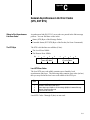
General Asynchronous Link Error Codes (STS, EXT STS) .
C1
Where to Find Asynchronous Link Error Codes . . . . . . . . . . . . . . .
The STS Byte . . . . . . . . . . . . . . . . . . . . . . . . . . . . . . . . . . . . . .
The EXT STS Byte . . . . . . . . . . . . . . . . . . . . . . . . . . . . . . . . . . .
C1
C1
C3
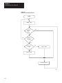
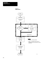
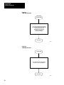
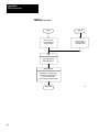
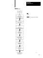
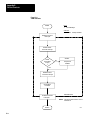
Detailed Flowcharts . . . . . . . . . . . . . . . . . . . . . . . . . . . . . .
D1
General . . . . . . . . . . . . . . . . . . . . . . . . . . . . . . . . . . . . . . . . . . .
D1
Data Link Layer . . . . . . . . . . . . . . . . . . . . . . . . . . . . . . . . .
E1
Data Link Layer Operation on Data Highway . . . . . . . . . . . . . . . . .
Floating Master . . . . . . . . . . . . . . . . . . . . . . . . . . . . . . . . . . . . .
Message Transmission . . . . . . . . . . . . . . . . . . . . . . . . . . . . . . . .
Polling . . . . . . . . . . . . . . . . . . . . . . . . . . . . . . . . . . . . . . . . . . . .
Data Security . . . . . . . . . . . . . . . . . . . . . . . . . . . . . . . . . . . . . . .
Link Disconnect . . . . . . . . . . . . . . . . . . . . . . . . . . . . . . . . . . . . .
E1
E1
E3
E3
E4
E5
Chapter
1
Introduction
General
A 1770-KF2 Series B module is a communication interface that links
intelligent RS-232-C or RS-422-A (asynchronous) devices to an
Allen-Bradley local area network. By setting switches on the KF2, and
changing cables, you can direct communications over a Data Highway or
a Peer Communication Link (PCL). With a 1770-KF2 module, a
computer on a PCL can communicate with any PLC-5 node on the
network. Other current Allen-Bradley products that communicate over a
PCL are the 1784-T50 Industrial Terminal System and the 1785-KA
Communication Adapter Module.
The KF2 is designed to operate in a control-room environment on a
tabletop. It takes its power from an AC wall outlet, and it gives you a
choice of full-duplex or half-duplex protocol on its asynchronous link.
The module has Data Highway compatibility, and it supports all PCL
facilities except internetworking.
(Internetworking would indicate that a computer on a PCL could talk to a
node on another PCL, or to a station on a Data Highway link. That may
be possible in the future, but it isn’t right now. A computer on a Data
Highway, though, using a 1770-KF2 and a 1785-KA can communicate
with PLC-5s on a PCL.)
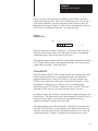
About This Manual
This manual describes installation, operation, and communication
protocols of a 1770-KF2 module; and it assumes that you are already
thoroughly familiar with how to program your computer or other
intelligent asynchronous device. It does not assume prior knowledge of
the Allen-Bradley Data Highway or a Peer Communication Link.
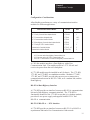
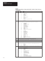
Table 1.A lists related documentation that might be helpful in conjunction
with this manual. For more details about the programming and operation
of specific Allen-Bradley programmable controllers, refer to the
appropriate user’s manual for that controller.
1-1
Chapter 1
Introduction
Table 1.A
Related Documentation
Publication
Number
Old Publication
Number
Title
1770-6.2.1
1770-810
Data Highway Cable Assembly and Installation
Manual
1771-6.5.1
1771-801
Communication Adapter Module
(Cat. No. 1771-KA2) User’s Manual
1771-6.5.15
1771-822
Communication Controller Module
(Cat. Nos. 1771-KE, -KF) User’s Manual
1771-6.5.8
1771-811
PLC-2 Family/RS-232-C Interface Module
(Cat. No. 1771-KG) User’s Manual
1775-6.5.1
1775-802
PLC-3 Communication Adapter Module
(Cat. No. 1775-KA) User’s Manual
1773-6.5.2
1773-801
PLC-4 Communication Interface Module
(Cat. No. 1773-KA) User’s Guide
1785-6.8.1
PLC-5/15 Processor Manual
1785-6.6.1
PLC-5/15 Assembly & Installation Manual
6226-6.5.1
Industrial Terminal Support Software System
Manual
1784-6.5.1
Industrial Terminal (1784-T50) User’s Manual
1785-6.5.1
PCL-to-Data Highway Communication Adapter
Module (1785-KA) User’s Manual
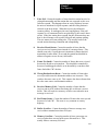
This manual is organized as follows:
Chapter 2 — Explains basic communication concepts.
Chapter 3 — Tells how to install a KF2 module.
Chapters 4, 5, and 6 — Describe the communication protocol used by
a KF2 module.
Chapter 7 — Summarizes error reporting.
1-2
Chapter 1
Introduction
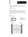
Module Description
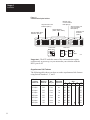
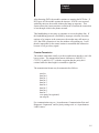
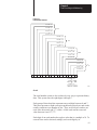
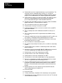
Figure 1.1 shows the 1770-KF2 module’s hardware features:
Diagnostic Indicators
Connectors for Data Highway and RS-232-C Devices
Communication Option Switches
On/Off Switch, Power Plug, Fuse, and Voltage Select Switch
Figure 1.1
1770-KF2 Communication Interface Module
ALLEN–BRADLEY
PWR
XMTG RCVG RDY
ACTV CPU
DATA HIGHWAY
COMMUNICATION INTERFACE
A KF2 also features extensive self-diagnostics. At power-up, tests are run
on internal memory, timers, and firmware integrity. Any failure causes
the red front-panel CPU indicator to flash. Also, the module continuously
checks the memory and firmware during operation.
1-3
Chapter 1
Introduction
Specifications
Table 1.B lists KF2 module specifications.
Table 1.B
KF2 Module Specifications
Specification
Communication Rates
Requirements
•
•
•
Functions
•
•
Interface a programmable RS-232-C or RS-422-A
compatible device with an Allen-Bradley Data Highway.
Serve as a replacement for a 1771-KD Communication
Controller Module.
Location
•
•
Tabletop (or other horizontal surface)
Controlled environment, e.g., office or control room
Communication Ports
•
•
Data Highway: 15-pin male EIA D-connector
Peer Communication Link: 15-pin male EIA
D-connector
Data Highway Monitor: 9-pin female EIA D-connector
Asynchronous (RS-232-C/RS-422-A): 25-pin male
EIA D-connector
•
•
Cabling
•
•
•
Data Highway: Data Highway Dropline Cable
(Cat. No. 1770-CD)
Asynchronous RS-232-C: User-Supplied Data
Terminal Interface Cable or Modem Interface Cable
Asynchronous RS-422-A: User-Supplied Data Terminal
Interface Cable
Power Requirements
•
•
Selectable: 115 V/60 Hz or 230 V/50 Hz
Watts: 3.5
Ambient Temperature
Rating
•
•
32oF to 113oF (0oC to 45oC) Operational
-40oF to 185oF (-40oC to 85oC) Storage
Ambient Humidity Rating
•
10% to 80% Non-Condensing
Physical
•
Size: 10-3/8 in. x 10.0 in. x 3-3/8 in. (263.5 mm x
254 mm x 85.7 mm)
Weight: 6.0 pounds (2.7 Kg)
•
1-4
Data Highway: 57,600 bits per second (recommended)
Peer Communication Link: 57,600 bits per second
(recommended)
Asynchronous: Switch selectable from 110 to 9.600 bits
per second
Chapter 1
Introduction
Data Highway Applications
A KF2 module provides either a point-to-point link or a multi-drop link
between an Allen-Bradley Data Highway and an intelligent asynchronous
device. By “intelligent asynchronous device” we mean any device that
complies with RS-232-C or RS-422-A electrical standards and that can be
programmed to handle the communication protocol described in
Chapters 4 through 6 of this manual. Throughout this manual, we will
also use the term “computer” in a general sense to refer to this type of
device. Some examples include:
An Allen-Bradley Advisor 2+TM Color Graphic System
A PLC-3 Programmable Controller and Connected Communication
Adapter Module (Cat. No. 1775-KA)
A PLC-2 Family Programmable Controller and Connected PLC-2
Family/RS-232-C Interface Module (Cat. No. 1771-KG)
A PLC-4 Microtrol Programmable Controller and Connected
Communication Interface Module (Cat. No. 1773-KA)
A Variety of Minicomputers and Microcomputers
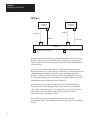
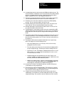
In point-to-point configuration, the KF2 module connects one intelligent
asynchronous device as a single station on a Data Highway. Figure 1.2
illustrates this configuration. Point-to-point links can use either peer-topeer (full-duplex) or master-slave (half-duplex) communication.
Figure 1.2
Point-to-Point Links
Computer
Modem
Modem Link
Modem
Computer
Asynchronous Link
(50 Cable-Ft. Max.)
KF2 Module
KF2 Module
KF2 Module
Allen–Bradley Longline
RS-232-C Link
(7,000 Cable-Ft. Max.)
Data Highway Link
1771-KG
Module
PLC-2/30
Processor
11687
1-5
Chapter 1
Introduction
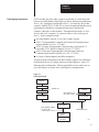
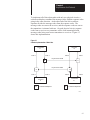
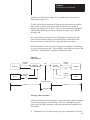
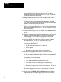
In a multi-drop configuration, one intelligent asynchronous device
connects to several Data Highways through sets of modems and KF2
modules. Figure 1.3 illustrates this type of configuration. If the
multi-drop link consists of broadband modems, you can select either
peer-to-peer (full-duplex) or master-slave (half-duplex) communication.
If the multi-drop link consists of baseband modems, you must use
master-slave (half-duplex) communication because baseband modems
support only one communication channel.
Figure 1.3
Multi-Drop Link
Computer
Modem
Multi-Drop Modem Link
Modem
Modem
KF2 Module
1771-KG
Module
Data Highway Link
PLC-2/15
Processor
1775-KA
Module
1773-KA
Module
PLC-3
Processor
PLC-4
Microtrol
Processor
Modem
KF2 Module
Data Highway Link
KF2 Module
Computer
1771-KA
Module
1774-KA
Module
PLC-2
Processor
PLC
Processor
11688
1-6
Chapter 1
Introduction
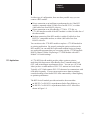
In either type of configuration, there are three possible ways you can
connect a KF2 module:
Direct connection to an intelligent asynchronous device if the KF2
module is mounted within 50 cable-feet of an RS-232-C, or within
4,000 cable-feet of an RS-422-A device.
Direct connection to an Allen-Bradley 1775-KA, 1773-KA, or
1771-KG interface module if the KF2 module is within 50 cable-feet of
the other module.
Modem connection if the KF2 module is within 50 cable-feet of an
RS-232-C compatible modem, or within 4,000 cable-feet of an
RS-422-A device.
You can also use the 1770-KF2 module to replace a 1771-KD module in
an existing application. By properly setting the option switches on the
KF2 module, you can make this replacement without having to change
any application programs that you were using with the 1771-KD module.
Refer to Chapter 3 under “Replacing a 1771-KD Module with a KF2
Module” for switch settings.
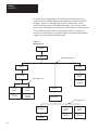
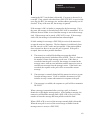
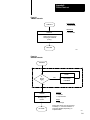
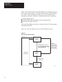
PCL Applications
A 1770-KF2 Series B module provides either a point-to-point or
multi-drop link between an Allen-Bradley Peer Communication Link
(PCL) and an intelligent asynchronous device. You can use a PCL link
when you have a small number of PLC-5/15 stations in a local cluster.
Typically, a PCL link connects PLC-5/15s that need to communicate with
each other frequently. If your system requires more than ten stations,
consider breaking it into smaller PCL links connected by a Data Highway
to optimize performance.
The KF2 Series B module provides an interface between either:
an RS-232-C or RS-422-A asynchronous link to Data Highway, or
an RS-232-C or RS-422-A asynchronous link to a PCL network as
shown in Figure 1.4.
1-7
Chapter 1
Introduction
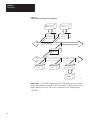
Figure 1.4
A PCL Network Connected to a Data Highway
Advisor 2+ TM
PLC-3
1770-KF2
1775-KA
Data Highway
1785-KA
PCL
PLC-5
PLC-5
1770-KF2
Computer
14690
Important: A 1770-KF2 module on a PCL link cannot access a station
on the Data Highway through a 1785-KA module. A KF2 module on the
Data Highway, however, can access a station on a PCL link through a
1785-KA.
1-8
Chapter
2
Communication Concepts
General
This chapter presents some of the concepts of communication with the
KF2 module. It describes the physical communication links to the module
and the various levels of software necessary to make those links work.
A KF2 module connects a computer or programmable controller to an
Allen-Bradley local area network (LAN), either Data Highway or Peer
Communication Link (PCL). In doing so, the module acts as an interface
between two physical communication links:
Data Highway or PCL, Called “Network Link”
RS-232-C or RS-422-A, Called “Asynchronous Link”
A Data Highway network provides peer-to-peer communication between
the KF2 module and other stations on the Data Highway. It uses a
half-duplex (polled) protocol and rotation of link mastership.
A Peer Communication Link provides peer-to-peer communication
between the KF2 module and other stations on the PCL. The PCL uses
token-passing to control access to the link.
The asynchronous link can provide either peer-to-peer communication
through a full-duplex (unpolled) protocol, or master-slave communication
through a half-duplex (polled) protocol.
In addition to a physical link layer, communication on either the network
link or the asynchronous link involves three levels of software:
Application Layer
Network Layer
Data Link Layer
If you are using a computer on an asynchronous link, you must program
all three layers. For A-B programmable controllers, you need program
only the application layer; the Data Highway interface modules (or for the
PCL, the PLC-5 itself) automatically take care of the other two layers.
The rest of this chapter presents some of the concepts behind the physical
communication links and their three software layers. For more details on
2-1
Chapter 2
Communication Concepts
the application and network layers, refer to Chapters 5 and 6. For more
on the data link layer of the asynchronous link, refer to Chapter 4 and
Appendix D.
Physical Link Layer
The physical link layer is a set of cables and interface modules that work
together to provide a channel for communication between the various
points, called stations, on the physical link. A station consists of an
intelligent programmable device (e.g., PC or computer) and the module or
modules that interface it with the physical link.
In this way, the KF2 module allows stations on one link to communicate
with stations on the other link. Since these two physical links have
different communication protocols, the KF2 module serves mainly as a
protocol translator.
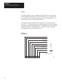
Data Highway
The Data Highway and the PCL are both local area networks (LANS) that
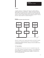
allow peer-to-peer communication among up to 64 stations. Figure 2.1
illustrates a Data Highway network.
The Data Highway link consists of a trunkline that can be up to
10,000 feet long and droplines that can be up to 100 feet each. Each
station is at the end of a dropline.
A Data Highway link implements peer-to-peer communication through a
modified token-passing scheme called the floating master. With this
arrangement, each station has equal access to become the master. The
stations bid for temporary mastership based on their need to send
information.
Unlike a master/slave relationship, a floating master relationship does not
require the current master to poll each station to grant permission to
transmit. Therefore, it provides a more efficient network because there is
less overhead per transaction.
2-2
Chapter 2
Communication Concepts
Figure 2.1
Data Highway Network
PLC-3
Processor
Computer
TM
1775-KA
Module
Advisor 2+
MODEM
RS-232-C Link
50 Cable-Ft. Max.
MODEM
Link
MODEM
1770-KF2
Module
1770-KF2
Module
Data
Highway
Link
1770-KF2
Module
RS-232-C Link
50 Cable-Ft. Max.
1771-KA
Module
1773-KA
Module
1771-KG
Module
PLC-2/15
Processor
PLC-4
Loop
PLC-2/30
Processor
11299A
Stations
A station consists of a computer or PC processor and the module or
modules that interface it with the Data Highway link. Within a station
that contains a KF2 module, an asynchronous link is required as an
auxiliary link to the network. Figure 2.1 shows three such stations.
2-3
Chapter 2
Communication Concepts
One station consists of an Advisor 2+TM Color Graphic System connected
to a KF2 module through an RS-232-C link limited to 50 cable-feet.
Another station consists of a computer interfacing with a KF2 module
through a modem link that is limited only by the nature of the modems
themselves.
The third such station consists of a 1771-KG module interfacing a
PLC-2/30 processor with a KF2 module through an RS-232-C link limited
to 50 cable-feet. If you want a link longer than 50 cable-feet, you can use
modems.
PC Programming
All Allen-Bradley PC processors can be connected to a Data Highway
through an appropriate station interface module. All of these processors
can receive and reply to command messages, and some of them can also
transmit command messages. For an explanation of how to program PCs
to send and receive messages, refer to the user’s manual for the
appropriate station interface module.
Computer Programming
The communication protocol for the Data Highway link is transparent to a
computer on the network. However, for a computer to send or receive
messages through the Data Highway network, it must be programmed to
communicate with its KF2 module over an asynchronous link.
Chapters 4, 5, and 6 describe the protocol that you must program your
computer to use on such an asynchronous link.
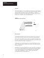
Peer Communication Link
A PCL has much the same topology as the Data Highway, described in the
previous chapter; but it is designed for fewer, closely coupled, PCs. The
PCL implements peer-to-peer communication with a token-passing
scheme to rotate link mastership among the stations connected to that link.
Since such a method does not require any polling, it is very time efficient.
The PCL also uses timeouts to recover from any fault that disables the
station that has the token.
2-4
Chapter 2
Communication Concepts
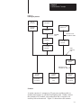
Stations
A station consists of a computer, or PC processor, and the module or
modules that interface it with the PCL. Within a station that contains a
KF2 module, an asynchronous link is required as an auxiliary link to the
network. PCL networks currently use PLC-5 processors, which interface
directly to the PCL; and no station interface module is required. You can,
however, connect other PCs, as shown in Figure 2.2.
Figure 2.2
PCL Network Connected to Various PC Processors
PLC-4
Loop
1773-KA
Module
KF2
Module
PLC-3
Processor
PLC-2/30
Processor
1775-KA
Module
1771-KG
Module
KF2
Module
KF2
Module
PCL
11300A
Other PCL stations can be computers that interface with the KF2 module
either directly or through a modem link, or a PCL-to-Data Highway
communication adapter (1785-KA), which you can use to connect a PCL
to the Data Highway.
PC Programming
All Allen-Bradley PC processors can receive command messages and
reply to them, and some can transmit commands. For an explanation of
how to program PCs to send and receive messages, refer to the user’s
manual for that particular station interface module or, in the case of a
PLC-5, the processor itself.
2-5
Chapter 2
Communication Concepts
Computer Programming
The communication protocol for the PCL is transparent to a computer on
the network. However, for a computer to send or receive messages
through the PCL, it must be programmed to communicate with its KF2
module over an asynchronous link. Chapters 4, 5, and 6 describe the
protocol that you must program your computer to use on this link.
Configuration Selection
Figure 2.1 and Figure 2.2 illustrate configurations in which PC stations
can communicate with each other and with computers through network
ports and asynchronous ports on the station interface modules. Each
configuration is useful, depending on your application.
If you want to provide a peer-to-peer communication among many PCs
and/or a computer, use a Data Highway network as shown in Figure 2.1.
For communication among a small cluster of PCs and a computer, use a
PCL as shown in Figure 1.4. For distances longer than the networks
provide, you can use an auxiliary longline asynchronous (RS-232-C or
RS-422-A) link or a modem link.
A Data Highway link has a communication rate of 57,600 bits per second
and a half-duplex (peer-to-peer, polled) protocol. A KF2 asynchronous
link is selectable RS-232-C/RS-422-A and has a selectable
communication rate up to 9,600 bits per second. It uses a selectable
protocol of half-duplex (master-slave polled) or full-duplex (peer-to-peer,
unpolled).
A master-slave communication protocol can be selected for any link to a
computer. A peer-to-peer communication protocol can be selected only
for a point-to-point link or a broadband modem multi-drop link to a
computer.
Even with only two stations, you may want a Data Highway or a Peer
Communication Link. Either network provides the flexibility of easy
reconfiguration or expansion if you want to be able to add more stations
later, and it also provides more error checking than an asynchronous link.
2-6
Chapter 2
Communication Concepts
Configuration Considerations
Allen-Bradley manufactures a variety of communication interface
modules for different applications:
Communication Interface Module
Cat. No.
Note
PLC Communication Adapter Module
1774-KA
1
PLC-2 Family Communication Adapter Module
1771-KA2
1
PLC-3 Communication Adapter Module
1775-KA
1&2
PLC-4 Communication Interface Module
1773-KA
1&2
PLC-5/Data Highway Communication Adapter Module
1785-KA
––
PLC-2 Family/RS-232-C Interface Module
1771-KG
2
Communication Controller Modules
1771-KE, -KF
3
Communication Interface Module
1770-KF2B
3
Provides interface between:
1
2
3
A PC Processor and a Data Highway Communication Link
A PC Processor and an RS-232-C Communication Link
A RS-232-C Communication Link and a Data Highway Communication Link
A 1785-KA module interfaces a Data Highway with a Peer
Communication Link. The module resides in a 1771 I/O rack and
receives its power from the rack’s backplane.
A 1771-KE module must be installed in an I/O chassis. The 1771-KD,
1771-KF, and 1770-KF2 are standalone modules. Modules 1771-KE,
1771-KF, and 1770-KF2 provide either peer-to-peer or master-slave
communication between an RS-232-C link, or to a modem link, and the
Data Highway.
RS-422-A/Data Highway Interface
A 1770-KF2 provides an interface between an RS-422-A communication
link and a Data Highway communication link. The 1770-KF2 is
functionally identical to the 1771-KF except that it is a desktop module,
provides its own power supply, and supports both RS-232-C and
RS-422-A communication.
RS-232-C/RS-422-A — PCL Interface
A 1770-KF2 provides an interface between an RS-232-C or RS-422-A
asynchronous link and a Peer Communication Link network.
2-7
Chapter 2
Communication Concepts
Software Layers
Each of the physical links just described requires three layers of software
to enable communication to take place. The layers are defined as follows:
Application Layer — Controls and executes the actual tasks, or
commands, specified in the communication between stations. To
program this layer, use the commands described in Chapter 5.
Network Management Layer — Handles queueing, sequencing,
routing, and error status reporting for communication. If your physical
link contains only Allen-Bradley PCs, you do not have to program this
layer. Otherwise, refer to Chapter 5 for a description of how to
program this layer for an asynchronous link to a computer.
Data Link Layer — Controls the flow of communication over the
physical link by establishing, maintaining, and releasing the
communication channel between stations. If your physical link
contains only Allen-Bradley PCs, you do not have to program this
layer. Otherwise, refer to Chapter 4 for a description of how to
program this layer for an asynchronous link to a computer.
Application Layer
The application layer concerns the specific commands that you can
program at a given station to cause that station to communicate over the
link. This layer is the same for both asynchronous and network links.
The types of commands that a station can transmit and receive vary with
the type of processor at that station. Chapter 5 describes the commands
that each type of PC processor can transmit or receive. To program your
computer to communicate with a PC, use the appropriate command
message format shown in Chapter 5.
Message Structures
All messages on a network have the same fundamental structure,
regardless of their function or destination. If you could freeze a block
while it is in transmission, you would see two types of message bytes:
Protocol Bytes
Data Bytes
Protocol bytes are used by the network to get the message to its
destination. Data bytes are delivered to the application at the destination.
The methods by which these bytes are filled is determined by the nature
of the station from which the transmission block originates. For example,
if a transaction originates from a PC station, the station interface module
2-8
Chapter 2
Communication Concepts
automatically fills the protocol bytes. If the transaction originates from a
computer station, your computer software must supply the necessary
protocol. In both cases, the data bytes contain information supplied by
application programs.
Command/Reply Cycle
Any network transaction consists of two messages: a command and a
reply.
The two parts provide extra data integrity by ensuring that a required
action always returns some sort of status, whether an error code or data.
As a frame of reference, the command initiator is always referred to as a
local station, and a reply initiator is always referred to as a remote station.
Unless noted otherwise, whether in a network link or an asynchronous
link, our reference will be limited to a single local station and a single
remote station.
The network layer protocol distinguishes a command from a reply.
Obviously, the data area of a command and its corresponding reply
depend on the type of command.
Priority
Each message on a Data Highway link is classified as either high priority
or normal priority.
Each message on a PCL is classified as normal priority.
Priority levels of messages determine the order in which stations are
polled and allowed to transmit messages. In the polling process, stations
with high priority messages will always be given priority over stations
with normal priority messages.
You specify the priority level for each command in the message command
code. The station that receives a command message must establish the
same priority level for its corresponding reply message.
Important: Stations with high priority messages are given priority over
stations with normal priority messages throughout the command/reply
message cycle. For this reason, a command should be given a high
priority designation only when special handling of specific data is
2-9
Chapter 2
Communication Concepts
required. Using an excessive number of high priority commands defeats
the purpose of this feature and could delay or inhibit the transmission of
normal priority messages.
Command Structures
There are four basis types of command on a Data Highway network or a
standalone link:
Read
Write
Diagnostic
Mode Select
Reads
There are two types of read:
Physical
Unprotected
A physical read allows you to read any area of PC memory at a remote
station. However, a PC processor cannot originate a physical read
command; only a computer can originate a physical read.
An unprotected read can access only the data table area of PC memory.
Both computers and PCs can initiate unprotected reads.
Any read can request up to 122 16-bit words of contiguous data from PC
memory.
Writes
We can classify write commands both by their application and by their
level of memory access.
As an application issue, writes are divided between bit writes and
word writes. Bit writes allow the local station to control bits in the
data table of a remote station.
Word writes allow the local station to write up to 121 contiguous words of
data into the remote station’s memory, provided you abide by the
restrictions on memory access discussed next.
2-10
Chapter 2
Communication Concepts
As with reads, writes also are classified by the level of access to PC
memory. Non-physical writes can access only the data table at a remote
PC; physical writes can access all of user memory, including PC program
memory.
Non-physical writes can be further subdivided into protected and
unprotected. Protected writes can access only specified areas of the
remote PC’s data table memory. The accessible areas are defined by
memory protection rungs in the remote PC’s ladder diagram program.
Unprotected writes, on the other hand, can access any area of the remote
PC’s data table.
In most cases, switch settings on the remote station’s interface module can
disable the module from executing each of these types of write
commands.
Diagnostics
Diagnostic commands have to originate from a device other than a PC.
You can use these commands to return status information from a remote
or local station or to alter some on-board parameters at a station interface
module. Diagnostic commands are particularly useful during a start-up or
during on-line debugging.
Mode Select
Mode select commands allow you to load a new PC program from a
remote computer station. The operation of these commands varies by PC
processor type. These commands can be issued only by a computer.
Network Management Layer
The network management layer is concerned with the specifics of
conveying a message safely from its source to its destination. This layer
is the same for both asynchronous and network links.
If your physical link contains only Allen-Bradley PCs, you do not have to
program anything for this layer; the communication interface modules
automatically take care of it. If your physical link contains a computer,
then refer to Chapter 5 for a description of how to program this layer at
the computer station.
2-11
Chapter 2
Communication Concepts
Generally, you need not be concerned with the interaction of station
interface modules on the network.
This means that your application programs at the PCs and computers
along the network need not involve themselves with interstation protocol,
handshaking, or control of the network link. This is all carried out
automatically by the station interface modules. However, an
understanding of station interaction is useful both to computer
programmers and PC programmers. It allows optimum use of network
commands and fault diagnostics.
Error Checking
Error codes can be generated at two places: remote station modules and
local station interface modules. For codes that are returned from a local
station module, two types of condition can exist:
Application programs use the wrong message format or issue illegal
commands.
The local station cannot complete a transaction due to network
problems.
A remote station can return only the codes associated with an application
problem at the remote station. Typically, these involve either the PC
processor being off-line (in Program mode, for example) or the command
trying to access memory areas blocked by either the interface module or
the user application program.
In the network layer protocol, command message status is returned in a
reply status byte. A value of zero in the status byte indicates successful
transmission of the corresponding command. It is up to the local
application program to display and act on the value of the returned byte.
2-12
Chapter
3
Installation
General
This chapter explains how to install the 1770-KF2 module. There are four
parts to installation:
Setting Communication Option Switches
Situating the Module for Operation
Connecting the Module to the Network and Asynchronous Links
Observing the Diagnostic Indicators
Please read the first three chapters of this manual carefully before
attempting any of the installation steps.
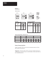
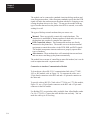
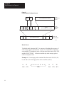
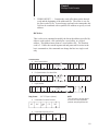
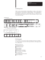
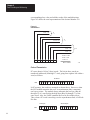
Communication Option Switches The KF2 module has 8 switch assemblies (Figure 3.1) that enable you to
select various communication options. The switch assemblies and their
corresponding options are:
Switch Assembly
Communication Option
SW-1
Asynchronous Link Features
SW-2, SW-3, SW-4
Station Number
SW-5
Network Link Communication Rate
SW-6
Asynchronous Link Communication Rate and Diagnostic
Commands
SW-7
Selecting the Network Link
SW-8
RS-232-C/RS-422-A Selection
3-1
Chapter 3
Installation
Figure 3.1
Communication Option Switches
Network Link
Communication
Rate (SW-5)
Asynchronous Link
Features (SW-1)
Station Number
(SW-2, SW-3, SW-4)
RS-232-C/RS-422-A
Selection (SW-8)
O 1
N
2
O
F
F
Asynchronous Link
Communication
Rate (SW-6)
O 1 2 3 4 5
N
O 1
N
O
F
F
O
F
F
2
O 1
N
2
3
O
F
F
O 1
N
Network Link
Selection
(SW-7)
2 3
O
F
F
Front View
O 1 2
N
O
F
F
O 1
N
2
O
F
F
O 1 2 3 4
N
O 1
N
O
F
F
O
F
F
2
Side View
ÉÉ
É
ON
ON
ON
OFF
OFF
OFF
13529
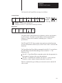
Important: The KF2 reads the status of the communication option
switches only at power-up, so you must make your selection with the
KF2’s power off.
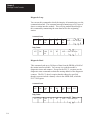
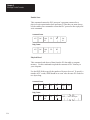
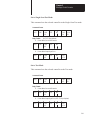
Asynchronous Link Features
The following table shows you how to set the asynchronous link features
using Switch Numbers 1, 2, and 5.
If You Want
to Select
Protocol as:
3-2
With Error
Check as:
With
Parity as:
With
Embedded
Responses:
1
2
SW-1
3
4
5
Full Duplex
BCC
None
No
OFF
OFF
N/A
N/A
OFF
Full Duplex
BCC
Even
No
ON
OFF
OFF
Full Duplex
BCC
None
Yes
OFF
ON
OFF
Full Duplex
BCC
Even
Yes
ON
ON
OFF
Half Duplex
BCC
None
No
OFF
OFF
ON
Half Duplex
BCC
Even
No
ON
OFF
ON
Full Duplex
CRC
None
Yes
OFF
ON
ON
Half Duplex
CRC
None
No
ON
ON
ON
Chapter 3
Installation
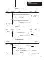
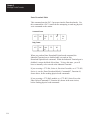
Switch 3 determines whether the asynchronous port of the KF2 module
can detect duplicate messages transmitted to it.
If You Want Your Module to:
Set Switch 3:
Detect and Ignore Duplicate Messages
ON
Accept All Messages Regardless of Duplication
OFF
Switch 4 determines whether the module uses and recognizes the
following handshaking signals: data set ready, request to send, clear to
send, data carrier detect, and data terminal ready.
If You Want the Module’s Asynchronous Port to:
Set Switch 4:
Use Handshaking Signals
ON
Ignore Handshaking Signals
OFF
Important: If you select half-duplex, the KF2 uses handshaking signals
even if Switch 4 is set OFF.
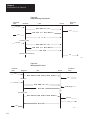
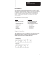
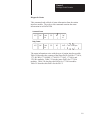
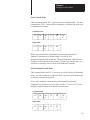
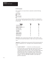
Station Number
Switch Assemblies SW-2, SW-3, and SW-4 are for setting the network
station number of the KF2 module. For the Data Highway, the station
number is a 3-digit octal number that identifies the KF2 module as a
unique station. Valid station numbers for the KF2 module in Data
Highway mode are 010 to 077 and 110 to 376 octal. For a PCL, the
station number is 2 digits; set both switches in SW-2 OFF. Valid station
numbers for the KF2 in PCL mode are 00 to 77 octal.
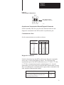
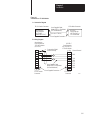
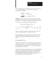
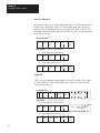
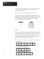
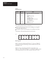
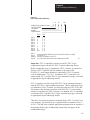
Figure 3.2 shows an example of how to set the KF2 station number to
037 octal. The switches in Assembly SW-2 set the first (left-most) digit
of the station number; Switch Assembly SW-3 sets the middle digit; and
Switch Assembly SW-4 sets the last (right-most) digit.
Station numbers play an important part in the polling scheme described in
Chapter 2. They can also influence the order in which mastership is
transferred between network stations. Therefore, we recommend that you
always begin numbering stations with the lowest possible number and
continue with the next available number in sequence.
3-3
Chapter 3
Installation
Figure 3.2
Station Number
Switch Groups
SW-2
O 1
N
2
O
F
F
SW-3
O 1
N
2
ON
SW-4
O 1
N
3
O
F
F
2
OFF
3
O
F
F
First Digit
ON
ON
OFF
OFF
Second and Third Digits
Set Switches
If You Want
to Set This
Digit:
No. 1
No. 2
0
1
2
3
OFF
OFF
ON
ON
OFF
ON
OFF
ON
Set Switches
If You Want
to Set This
Digit:
No. 1
No. 2
No. 3
0
1
2
3
4
5
6
7
OFF
OFF
OFF
OFF
ON
ON
ON
ON
OFF
OFF
ON
ON
OFF
OFF
ON
ON
OFF
ON
OFF
ON
OFF
ON
OFF
ON
Switch Setting Example: Station No. 037
Switch Group
SW-2
Station No. Digits
Switch No.
Switch Setting
SW-3
0
SW-4
3
7
1
2
1
2
3
1
2
3
OFF
OFF
OFF
ON
ON
ON
ON
ON
13531
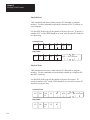
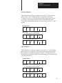
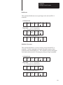
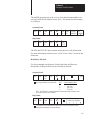
Network Communication Rate
Switch Assembly SW-5 lets you select the communication rate for the
KF2 module’s network link.
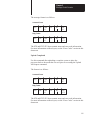
Important: Set both switches ON for a network communication rate of
57,600 bits per second. Be sure to set all modules on the network link for
this communication rate.
3-4
Chapter 3
Installation
Figure 3.3
Switch Settings for Network Link
SW–5
O 1
N
2
Both switches ON for
57,600 bits per second
O
F
F
13514
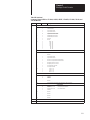
Asynchronous Communication Rate and Diagnostic Commands
Switch Assembly SW-6 lets you select the communication rate and
diagnostic commands for the KF2 module’s asynchronous port.
Communication Rate
Set the communication rate switches as shown:
Bits per
Second as:
110
300
600
1,200
2,400
4,800
9,600
1
OFF
ON
OFF
ON
OFF
ON
OFF
Set Switch:
2
OFF
OFF
ON
ON
OFF
OFF
ON
3
OFF
OFF
OFF
OFF
ON
ON
ON
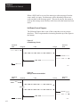
Diagnostic Commands
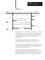
Switch 4 determines how the KF2 module treats diagnostic commands
sent to it by a remote Data Highway station. You can connect the
asynchronous port of the KF2 module directly to a 1771-KG, 1773-KA,
or 1775-KA communication interface module (Figure 1.2). In such
applications, you can set Switch 4 so that the KF2 module either executes
any received diagnostic commands itself or passes those commands to the
other attached communication module.
If You Want Your Module to:
Set Switch 4:
Execute Received Diagnostic Commands
ON
Pass Any Received Diagnostic Commands to the
Attached Asynchronous Device
OFF
3-5
Chapter 3
Installation
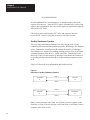
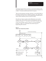
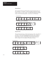
Switch 4 relates only to diagnostic commands sent to the KF2 module
from a remote Data Highway station. Since only computers can transmit
diagnostic commands, the remote station must be a computer connected to
the Data Highway by means of another KF2 module. At the computer
station, the setting of Switch 4 does not affect any diagnostic commands
that the computer sends to its local KF2 module. The local module
always retransmits the command message over the Data Highway without
executing it. Figure 3.4 illustrates these concepts.
Figure 3.4
Effect of Switch 4 on Diagnostic Commands
Switch 4 ON
1770-KF2 Module
Computer
1770-KF2 Module
Data
Highway
Link
1771-KG Module
PLC-2/15 Processor
To Other Stations
Diagnostic Command Path
Reply Message Path
Switch 4 OFF
1770-KF2 Module
Computer
1770-KF2 Module
Data
Highway
Link
To Other Stations
1771-KG Module
PLC-2/15 Processor
11691
You can have more than one computer station on a network, and one
computer can transmit diagnostic commands to the others. At the
receiving computer station, if Switch 4 is OFF, the local KF2 module will
pass the diagnostic commands to the computer. In such cases, you will
have to write computer application programs to handle those commands at
the receiving station. If Switch 4 is ON at the receiving station, the local
KF2 module itself will execute the incoming diagnostic commands.
3-6
Chapter 3
Installation
Selecting the Network Link
You use Switch Assembly SW-7, a spare assembly in all Series A
modules, to select whether the KF2 treats the network link as a Data
Highway or as a PCL.
The following table shows the settings for Switch Assembly SW-7:
For This Network:
Data Highway
Peer Communication Link
Set Switch 1: Set Switch 2:
OFF
OFF
ON
OFF
Selection of RS-232-C/RS-422-A
Switch Assembly SW-8 lets you select whether the asynchronous
interface uses RS-232-C or RS-422-A standard communication.
For Communication Using Standard:
RS-232-C
RS-422-A
Set Switch 1: Set Switch 2:
OFF
ON
ON
OFF
Important: This is the only option switch that affects KF2 operation
after power-up. It changes the voltage applied to the network link
connector pins to those required for the standard selected. Set this switch
BEFORE power-up.
Replacing a 1771-KD Module with a KF2 Module
By setting the switches properly on the KF2 module, you can use it to
replace an older 1771-KD module in an existing application without
having to make any changes in your application programs.
In Set
Switch
Switch Ass’y
No.
SW-1
1
2
3
4
5
SW-2
1, 2
SW-3
1, 2, 3
SW-4
1, 2, 3
SW-5
1, 2
SW-6
1, 2, 3
4
SW-7
1, 2
SW-8
1
2
Setting
OFF
Same Setting as 1771-KD Switch (Assembly SW-1, Switch 1)
OFF
OFF
OFF
Same Setting as 1771-KD Switches (Assembly SW-2, Switches 1 and 2)
Same Setting as 1771-KD Switches (Assembly SW-3, Switches 1, 2, and 3)
Same Setting as 1771-KD Switches (Assembly SW-4, Switches 1, 2, and 3)
Same Setting as 1771-KD Switches (Assembly SW-5, Switches 1 and 2)
Same Setting as 1771-KD Switches (Assembly SW-6, Switches 1, 2, and 3)
Same Setting as 1771-KD Switch (Assembly SW-1, Switch 5)
OFF
OFF
ON
3-7
Chapter 3
Installation
Important: The asynchronous port of the KF2 module can communicate
at a maximum rate of 9,600 bits per second. If your 1771-KD module
was set to communicate at a higher rate, then you might have to make
some modifications to your RS-232-C link before installing the
replacement KF2 module.
Mounting (Placing)
A KF2 module is not actually mounted in the sense that other
Allen-Bradley communication modules are. It is simply situated on a
surface, like a desktop, near a wall plug for AC power. It is set for 115V
operation when it reaches you. Connections to 115V AC and 230V AC
are described below.
Place the KF2 module within 100 cable-feet of the Data Highway
trunkline. If you are connecting the module directly to an RS-232-C
device, you must also mount the module within 50 cable-feet of that
device. If you are using a modem link to connect the KF2 module to the
asynchronous device, then the module and the device may be as far apart
as the modem link will allow. If you are connecting the KF2 directly to
an RS-422-A compatible device, you must mount the module within
4,000 cable-feet of that device.
115V AC Operation
The “power select” switch is above the ON/OFF switch on the module’s
rear panel. Set this switch to “115.” The power cord (approximately
7’4”), supplied with the module, must be plugged into the receptacle at
the right of the ON/OFF switch. Plug the other end of the power cord into
any standard 115V AC power outlet. Switch must be set before
power-up.
230V AC Operation
Set the “power select” switch to “230.” Do NOT use the power cord
supplied with the module. This cord is not approved for connection to a
230V AC outlet. To guard against electrical shock or fire, the power
supply cord must be approved for 230V AC by Underwriters Laboratories
or a similarly recognized agency. To mate with the receptacle on the
module’s rear panel, the power cord must be terminated in a molded
female connector (CEE 22 Standard V).
3-8
Chapter 3
Installation
Interface Connections
The KF2 module has 3 connectors on its rear panel (Figure 3.5). The
center connector, labeled DATA HIGHWAY, connects to the Data
Highway dropline cable. Plug the 15-pin connector of the dropline into
the DATA HIGHWAY socket. For connection to the PCL, plug the 15-pin
PCL dropline into the Data Highway socket. (For details on how to
construct the dropline, refer to Publications 1770-6.2.1 or 1770-2.13.)
The left connector, labeled DATA HIGHWAY MONITOR, is for future
product development. Do not make any connections to this socket.
The right connector, labeled COMPUTER ASYNCHRONOUS, connects
to an intelligent RS-232-C or RS-422-A compatible device. The rest of
this section explains how to make connections to this asynchronous
socket.
Figure 3.5
Dimensions of a 1770-KF2 Series B Module
10” (254.0 mm)
3-3/8”
(85.73 mm)
DATA HIGHWAY COMMUNICATION INTERFACE MODULE
9-1/8”
(231.78 mm)
SERIES
REV.
1770-KF2
MODEL NO.
Prototype
VOLTS
115/230V AC
DATA HIGHWAY
DATE
June 10/86
SERIAL NO.
Marketing
AMPS
0.30
∆τ
DATA HIGHWAY
MONITOR
CATALOG NO.
HERTZ
50/60
LM323K
8428
Designed and Manufactured
For
ALLEN-BRADLEY CO.
INDUSTRIAL COMPUTER GROUP
CLEVELAND, OHIO USA
By
DYNAPRO SYSTEMS INC.
VANCOUVER, B.C. CANADA
MADE IN CANADA
COMPUTER
ASYNCHRONOUS
WARNING
DISCONNECT POWER
BEFORE REMOVING
FUSE OR COVER
10-3/8” (263.53 mm)
3-9
Chapter 3
Installation
Mechanical Characteristics
The COMPUTER ASYNCHRONOUS connector on a KF2 module is a
male 25-pin D-shell. This connector conforms to the RS-232-C standard
and will accommodate any RS-232-C standard cable (see “Cabling”).
Electrical Characteristics
Selection of either RS-232-C or RS-422-A determines the input and
output levels of the transmit data and receive data circuits on the
asynchronous interface. When RS-232-C standard communication is
selected, all signals on the asynchronous interface are driven and received
by RS-232-C interface circuits which have a maximum drive capability of
50 cable-feet. When RS-422-A standard communication is selected, the
transmit and receive signals only are driven and received by RS-422-A
interface circuits which have a maximum drive capability of
4,000 cable-feet. In RS-422-A mode, all other signals except transmit and
receive still conform to RS-232-C.
The setting of Communication Option Switch 4 of Switch Group SW-1
determines whether the asynchronous port asserts the handshaking signals
or not (see “Asynchronous Link Features”). The handshaking signals are:
RTS, CTS, DSR, DCD, and DTR. When Switch 4 of SW-1 is ON, the
handshaking signals are used. When RS-422-A communications and
handshaking are both selected, handshaking signals are present; but they
conform to RS-232-C standards only.
Cabling
Cabling for the asynchronous port of the KF2 module will vary,
depending on your application and on whether you are using RS-232-C or
RS-422-A communications. The pinouts for the asynchronous connector
are as follows:
Pin
Signal
Protective Ground
Transmitted Data
Received Data
Request to Send
Clear to Send
Data Set Ready
Signal Ground
Data Carrier Detect
Data Terminal Ready
Transmitted Data A
Transmitted Data B
Received Data A
Received Data B
3-10
Abbreviation
TXD
RXD
RTS
CTS
DSR
GND
DCD
DTR
TDA
TDB
RDA
RDB
RS-232-C
1
2
3
4
5
6
7
8
20
RS-422-A
1
14
25
16
18
Chapter 3
Installation
The definitions of the above signals are:
TXD carries serialized data. It is an RS-232-C standard output from
the module.
RXD is RS-232-C standard serialized data input to the module.
RTS is a request from the module to the modem to prepare to transmit.
With full-duplex protocol, RTS is always asserted. With half-duplex
protocol, it is turned on when the module has permission to transmit;
otherwise it is off. It conforms to RS-232-C specifications.
CTS is a signal from the modem to the module that indicates the carrier
is stable and the modem is ready to transmit. The module will not
transmit until CTS is on. If CTS is turned off during transmission, the
module will stop transmitting until CTS is restored. It conforms to
RS-232-C specifications.
DTR is a signal from the module to the modem to connect to the phone
line (i.e., “pick up the phone”). The module will assert DTR all the
time except during the phone hang-up sequence. Modems built to
American standards will not respond to DTR until the phone rings.
Some European modems will always pick up the phone, whether it is
ringing or not. The KF2 module will not work with these types of
European modems. DTR conforms to RS-232-C specifications.
DSR is a signal from the modem to the module that indicates the phone
is off-hook. (It is the modem’s answer to DTR.) The module will not
transmit or receive unless DSR is on. If the modem does not properly
control DSR, or if no modem is used, DSR must be jumpered to a high
signal at the module’s asynchronous connector. (It can be jumpered to
DTR.) DSR conforms to RS-232-C specifications.
DCD is a signal from the modem to the module to indicate that the
carrier from another modem is being sensed on the phone line. It will
not be asserted unless the phone is off-hook. Data will not be received
at the asynchronous connector unless DCD is on. With full-duplex
protocol, the module will not transmit unless DCD is on. If the modem
does not properly control DCD, or if a modem is not being used, DCD
must be jumpered to DTR at the module. DCD conforms to RS-232-C
specifications.
TDA is the transmitted data signal for RS-422-A output from the
module.
TDB is the differential return signal for TDA for transmitting
RS-422-A data.
RDA is the RS-422-A data input to the module.
RDB is the differential return signal for RDA.
If you are connecting a KF2 module to an RS-232-C compatible device
(e.g., modem or computer), then you must mount the module within
50 cable-feet of that device. For such applications, the module’s GND
3-11
Chapter 3
Installation
must be connected to the GND of the modem or computer. Note that this
type of connection does not provide electrical isolation between the
module and the connected device.
If a connection is made between the KF2 and an RS-422-A compatible
device, you can mount the device and the module up to 4,000 cable-feet
apart.
Direct Connection to a Computer
To connect the module directly to a computer, you can construct your own
cable according to the wiring diagram in Figure 3.6.A. This cable plugs
into the COMPUTER ASYNCHRONOUS connector on the module and
the RS-232-C or RS-422-A compatible connector on the computer
(Figure 3.6.A). Connect the cable shield at one end only. Be sure that the
cable length does not exceed the RS-232-C limit of 50 feet or the
RS-422-A limit of 4,000 feet.
Figure 3.6
Connection to a Computer
A. Connection Diagram
25-Pin Female Connector
25-Pin Male Connector
Asynchronous
Port Connector
of 1770-KF2
Module (RS-232-C)
B. Wiring Diagram for RS-232-C
1
7
C. Wiring Diagram for RS-422-A
RS-232-C
Compatible Port
Connector of
Computer
Asynchronous
Port Connector
of 1770-KF2 Module
(RS-232-C)
Cable (Not
Exceeding 50 Feet)
Asynchronous
Port Connector
of 1770-KF2 Module
(RS-422-A)
1
7
Chassis Ground
Signal Ground
2
3
RXD
3
2
TXD
6
20
DTR
8
20
4
5
25-Pin Female
Connector
3-12
RS-232-C or
RS-422-A Compatible
Port Connector
of Computer
Cable
8
6
4
5
25-Pin Male
Connector
DCD
DSR
RTS
CTS
1
14
25
16
18
4
5
6
8
20
25-Pin Female
Connector
RS-422-A
Compatible Port
Connector of
Computer
Cable (Not
Exceeding 4,000 Ft.)
RDA
RDB
TDA
TDB
Note:
The connector and the pinouts for
the RS-422-A compatible computer
port will depend on the computer
manufacturer’s standard assignment.
Other pins may have to be jumpered
on the computer connector to ensure
proper operation.
11309
Chapter 3
Installation
This type of connection includes the DTR signal to allow each end to
detect the loss of the other end’s ability to communicate. If your
computer does not provide the DTR signal, jump Pins 6 and 8 at the KF2
module to Pin 20.
Connection to a Modem
To connect the module to a modem, you can construct your own cable
according to the wiring diagram in Figure 3.7. This cable plugs into the
COMPUTER ASYNCHRONOUS connector on the module and the
RS-232-C compatible connector on the modem (Figure 3.7). Connect the
cable shield at one end only. Be sure that the cable length does not exceed
the RS-232-C limit of 50 feet.
Figure 3.7
Connection to a Modem
A. Connection Diagram
25-Pin Female Connector
Asynchronous
PORT Connector
of 1770-KF2
Module (RS-232-C)
25-Pin Male Connector
Cable
RS-232-C
Compatible Port
Connector of
Modem
B. Wiring Diagram
RS-232-C
Compatible Port
Connector of
Modem
Asynchronous
Port Connector
of 1770-KF2 Module
(RS-232-C)
1
7
Cable (Not
Exceeding 50 Feet)
1
7
Chassis Ground
Signal Ground
2
2
TXD
3
3
RXD
4
4
RTS
5
5
CTS
6
6
DSR
8
8
DCD
20
20
DTR
25-Pin Female
Connector
25-Pin Male
Connector
14831
3-13
Chapter 3
Installation
The module can be connected to standard American dial-up modems and
some European modems. Other European standards specify that the DTR
signal will make the modem answer the phone whether it is ringing or not,
causing the phone always to be “busy.” Do not use the module with any
type of modem that answers the phone when DTR is asserted, even while
waiting for a call.
The types of dial-up network modems that you can use are:
Manual: These are typically acoustically coupled modems. The
connection is established by human operators at both ends, who insert
the handsets into couplers to complete the connection.
DTE-Controlled Answer: These unattended modems are directly
connected to the phone lines. The module serves as the data terminal
equipment to control the modem via the DTR, DSR, and DCD signals.
The module incorporates timeouts and tests to properly operate these
types of modems.
Auto-Answer: These modems have self-contained timeouts and tests
and can answer and hang up the phone automatically.
The module has no means of controlling an auto-dial modem, but it can be
used in conjunction with a separate auto-dialer.
Connection to Another Communication Module
To learn about a direct RS-232-C communication link with a 1771-KE,
-KF, or -KG module, refer to Figure 3.8. To construct the cable, use a
25-pin female connector at the KF2 end and a 15-pin male connector at
the other end.
To provide a direct RS-232-C link with a 1773-KA or a 1775-KA module,
Figure 3.9, use a 25-pin female connector at the KF2 and a 25-pin male
connector at the KA module.
Use Belden 8723 or equivalent cable (available from Allen-Bradley under
Cat. No. 1778-CR). Connect the cable shield at one end only. You can
make the cable up to 50 feet long.
3-14
Chapter 3
Installation
Figure 3.8
Connection to 1771-KG Module
A. Connection Diagram
25-Pin Female Connector
Asynchronous
Port Connector
of 1770-KF2
Module (RS-232-C)
User-Supplied Cable,
Belden 8723, or Equivalent
(50 Feet Maximum)
15-Pin Male Connector
RS-232-C
Port Connector
of 1771-KE/KF or
1771-KG Module
(Cat. No. 1778-CR)
User-Supplied Connectors
B. Wiring Diagram
Asynchronous
Port Connector of
1770-KF2 Module
(RS-232-C)
1
7
2
Connect the Shield
at One End Only
3
4
5
6
8
20
25-Pin Female
Connector
User-Supplied Cable,
Belden 8723, or Equivalent
(50 Feet Maximum)
User-Supplied Connectors
RS-232-C
Port Connector
of 1771-KE/KF or
1771-KG Module
1
3
13
2
14
4
5
6
8
11
15-Pin Male
Connector
Chassis Ground
RXD
TXD
TDA
RTS
CTS
DSR
DCD
11697
3-15
Chapter 3
Installation
Figure 3.9
Connection to 1773-KA or 1775-KA Module
A. Connection Diagram
25-Pin Female Connector
Asynchronous
Port Connector
of 1770-KF2
Module (RS-232-C)
User-Supplied Cable,
Belden 8723, or Equivalent
(50 Feet Maximum)
25-Pin Male Connector
RS-232-C
Port Connector
of 1773-KA or
1775-KA Module
(Cat. No. 1778-CR)
User-Supplied Connectors
B. Wiring Diagram
Asynchronous
Port Connector
of 1770-KF2 Module
(RS-232-C)
1
7
2
Connect the Shield
at One End Only
3
4
5
6
8
20
25-Pin Female
Connector
User-Supplied Cable,
Belden 8723, or Equivalent
(50 Feet Maximum)
User-Supplied Connectors
RS-232-C
Port Connector
of 1773-KA or
1775-KA Module
1
3
25
2
7
4
5
6
8
20
25-Pin Male
Connector
Chassis Ground
RXD
TDB
TXD
Signal Ground
RTS
CTS
DSR
DCD
DTR
11312
Answering
The module continually asserts DTR when it is waiting for a call. Under
this condition, the modem will answer a call and assert DSR as soon as it
detects ringing. The module does not monitor the RING indicator in the
RS-232 interface. Once it detects DSR, the module starts a timer (around
10 seconds) and waits for the DCD signal. When the module detects
DCD, communication can start.
If the module does not detect DCD within the timeout, the module turns
DTR off. This causes the modem to hang up and break the connection.
When the hang-up is complete, the modem turns off DSR. This causes
the module to reassert the DTR line and wait for another call. This
feature protects access to the phone if someone calling a wrong number
reaches this station.
3-16
Chapter 3
Installation
After detecting DCD, the module continues to monitor the DCD line. If
DCD goes off, the module restarts the timeout. If DCD is not restored
within the timeout, the module initiates the hang-up sequence. This
feature allows the remote station to redial in the event that the connection
is lost through a fault in the phone network.
This handshaking is necessary to guarantee access to the phone line. If
this handshaking protocol is defeated by improper selection of modem
options or by jumpers at the connectors, the modem may still answer a
call. But if the connection is lost, the modem will not hang up. It will
then be impossible for the remote station to reestablish the connection
because it will get a busy signal.
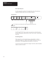
Character Transmission
The module sends data serially over the asynchronous interface, one 8-bit
byte at a time. The transmission format conforms to ANSI X3.16,
CCITT V.4, and ISO 1177, with the exception that the parity bit is
retained while the data length is extended to eight bits.
The transmission format may be summarized as follows:
start bit
data bit 0
data bit 1
data bit 2
data bit 3
data bit 4
data bit 5
data bit 6
data bit 7
even parity bit (optional)
one stop bit
For communication rate see “Asynchronous Communication Rate and
Diagnostic Commands” and for parity settings refer to “Asynchronous
Link Features.”
3-17
Chapter 3
Installation
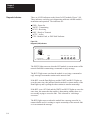
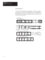
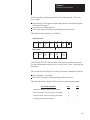
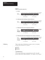
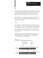
Diagnostic Indicators
There are 6 LED indicators on the front of a KF2 module (Figure 3.10).
These indicators can help you in diagnosing problems with the module’s
installation and operation. The indicators are:
PWR - Power On
XMTG - Transmitting
RCVG - Receiving
RDY - Ready to Transmit
ACTV - Active
CPU - Module Fault, or DLE NAK Indicator
Figure 3.10
Diagnostic (LED) Indicators
ALLEN–BRADLEY
PWR
XMTG RCVG RDY
ACTV CPU
DATA HIGHWAY
COMMUNICATION INTERFACE
The XMTG light comes on when the KF2 module is current master of the
network link and is transmitting a command or reply message.
The RCVG light comes on when the module is receiving a command or
reply message from another station on the network link.
If the KF2 is on the Data Highway and the XMTG and RCVG lights are
on at the same time, this indicates that the module is current master of the
Data Highway and is polling the other stations to transfer mastership.
If the KF2 is on a PCL link and the XMTG and RCVG lights are on at the
same time, this means that the module is determining whether there is a
new module trying to access the link. This is known as “soliciting a
successor.”
The RDY light comes on when the module has a message stored in its
transmit buffer and it is waiting to acquire mastership of the network link
so it can transmit the message.
3-18
Chapter 3
Installation
The ACTV light remains on as long as the cable between the
COMPUTER ASYNCHRONOUS socket and the interfacing
asynchronous device is properly connected. This light will appear to
flicker whenever characters are being transmitted across the asynchronous
link. If this light goes off, check the cable and connectors for possible
problems.
The CPU light comes on for about half a second every time the module
transmits or receives a DLE NAK protocol sequence (Chapter 4). If this
light flickers frequently or stays on, the asynchronous link might need
better isolation or noise immunity.
If the KF2 is on a PCL, the CPU light also flashes at about 1 Hz when a
duplicate node (two stations with the same station number) is detected and
stays on when an internal hardware fault is detected. For more on the
KF2 self-diagnostics, see Chapter 1 under “Module Description.”
3-19
Chapter
4
Asynchronous Link Protocols
General
This chapter describes the communication protocol used on the
asynchronous link to the KF2 module. If you are connecting a KF2
module to another Allen-Bradley communication interface module (such
as a 1771-KG, 1773-KA, or 1775-KA module), you need not be
concerned with protocol because the modules automatically take care of
it. However, if you are connecting a KF2 module to a computer, then you
must program the computer to understand and to issue the proper protocol
character sequences, as described in Chapters 4 through 6 of this manual.
Definition of Link Protocol
A link consists of a wire and associated hardware—such as transceivers,
UARTs, and error checkers. A link protocol carries a message error-free
from one end of the link to the other, or it indicates failure with an error
code. Internally it delimits messages, detects and signals errors, retries
after errors, and controls message flow. It requires that the link hardware
send characters from one end of the wire to the other.
The only purpose of a link protocol is to carry a message intact over a
link. It has no concern for the content of the message, the message’s
function in the operation of higher levels in the system, or the ultimate
fate or purpose of the message. Once the message has been reliably
carried from one end of the link to the other, the link protocol’s concern
for that message is ended.
The asynchronous port of the KF2 module can use one of two link
protocols, which are:
Full-Duplex Protocol (for Point-to-Point Communication)
Half-Duplex Protocol (for Master-Slave Communication)
In general, full-duplex protocol gives faster data throughput but is harder
to implement; half-duplex protocol is easier to implement but gives
slower data throughput. Each of these protocols is described
independently in “Full-Duplex Protocol” and “Half-Duplex Protocol”
respectively.
4-1
Chapter 4
Asynchronous Link Protocols
Important: Some Allen-Bradley documentation might refer to
full-duplex and half-duplex protocols as DF1 and polled-mode protocols,
respectively.
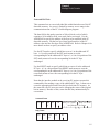
Full-Duplex Protocol
Full-duplex protocol conforms closely to ANSI X3.28-1976, combining
features of Subcategories D1 (data transparency) and F1 (two-way
simultaneous transmission with embedded responses).
Full-duplex protocol is used over a point-to-point link that allows
two-way simultaneous transmission. It is relatively difficult to implement
because it requires a system programmer to use interrupts and
multi-tasking techniques. It is intended for high-performance applications
where it is necessary to get the highest possible throughput from the
available communication medium.
Transmission Codes
Full-duplex protocol is character-oriented; it uses the following ASCII
control characters extended to eight bits by adding a zero for Bit 7. See
ANSI X3.4, CCITT V.3, or ISO 646 for the standard definition of these
characters.
Control Character
STX (Start of Text)
ETX (End of Text)
ENQ (Enquiry)
ACK (Acknowledge)
DLE (Data Link Escape)
NAK (Negative Acknowledge)
Hexadecimal Code
02
03
05
06
10
15
The term “code” is defined for use in the following paragraphs as an
indivisible sequence of one or more bytes having a specific meaning to
the link protocol. “Indivisible” means that the component characters of a
code must be sent one after another with no other characters between
them. It does not refer to the timing of the characters.
The following codes are used in full-duplex protocol:
Control Codes:
- DLE STX
- DLE ETX BCC/CRC
- DLE ACK
- DLE NAK
- DLE ENQ
4-2
Chapter 4
Asynchronous Link Protocols
Data Codes:
- Data (single characters having values 00-0F and 11-FF hex)
- DLE DLE (to represent the value 10 hex)
Codes are grouped into two classes: message codes, sent from transmitter
to receiver; and response codes, sent from receiver to transmitter.
DLE STX is a message code used to indicate the start of a message.
DLE ETX BCC/CRC is a message code used to terminate a message.
Data 00-0F and 11-FF hex are message codes used to encode the
corresponding values in the message itself. DLE DLE is a message
used to encode the occurrence of the value 10 in the message.
DLE ENQ is a message code. It requests the retransmission of the last
received code.
DLE ACK, a response code, signals that a message has been
successfully received.
DLE NAK, also a response code, signals that an attempt to transfer a
message has failed.
Link-Layer Message Packets
A link-layer message packet starts with a DLE STX and ends in a DLE
ETX BCC/CRC, with data codes in between. Data codes can occur only
inside a message packet. Response codes can also occur between a DLE
STX and a DLE ETX BCC/CRC, but such response codes are not part of
the message packet. They are referred to as embedded responses.
Figure 4.1 shows the format of a link-layer message packet for full-duplex
protocol, and the layer at which each portion should be implemented. At
the end of each message packet is the one-byte BCC field.
4-3
Chapter 4
Asynchronous Link Protocols
Figure 4.1
Packet Format for Full-Duplex Protocol
DST
SRC
DLE
STX
CMD
STS
CMD
STS
From
Application
Layer
Command/Response Block
From
Network
Layer
Data
(From Application Layer)
TNS
Data
(From Network Layer)
DLE
ETX
BCC
Data Link
Layer Packet
11321A
Block Check
The block check character (BCC) is a means of checking the accuracy of
each message packet transmission. It is the 2’s complement of the 8-bit
sum (modulo-256 arithmetic sum) of all data bytes between the DLE STX
and the DLE ETX BCC. It does not include any other message packet
codes or response codes.
Example 1: If a message packet contained the data codes 08, 09, 06, 00,
02, 04 and 03, the message packet codes would be (in hex):
4-4
10
02
DLE
STX
08 09 06 00 02 04 03
Data
10
03
E0
DLE
ETX
BCC
Chapter 4
Asynchronous Link Protocols
The sum of the data bytes in this message packet is 20 hex. The BCC is
the 2’s complement of this sum, or E0 hex. This is shown in the
following binary calculation:
0010 0000
1101 1111
+1
1110 0000
20 hex
1’s complement
2’s complement (E0 hex)
Example 2: To transmit the data value 10 hex, you must use the data
code DLE DLE. However, only one of these DLE data bytes is included
in the BCC sum. For example, to transmit the values 08, 09, 06, 00, 10,
04, and 03 hex, you would use the following message codes:
Represents Single Data Byte Value of 10
10
02
DLE
STX
08 09 06 00 10 10 04 03
Data
10
03
D2
DLE
ETX
BCC
In this case, the sum of the data bytes is 2E hex because only one DLE
text code is included in the BCC. So the BCC is D2 hex.
The BCC algorithm provides a medium level of data security. It cannot
detect transposition of bytes during transmission of a packet. It also
cannot detect the insertion or deletion of data values of zero within a
packet.
Cyclic Redundancy Check
Calculate the CRC value on the value of the data bytes and the ETX byte
(using the polynomial x16 + x15 + x2 + x0). To transmit the data value of
10 hex, you must use the data code DLE DLE. However, only one of
these DLE data bytes is included in the CRC value. Embedded responses
are not included in the CRC value.
At the start of a message packet, the transmitter clears a 16-bit register for
the CRC value. As a byte is transmitted, it is exclusive-ORed (with Bit 0
to the right) to the right eight bits of the register. The register is then
shifted right eight times with zeros (0s) inserted on the left. Each time a
one (1) is shifted out on the right the following binary number is
exclusive-ORed with the 16-bit register value:
4-5
Chapter 4
Asynchronous Link Protocols
1010 0000 0000 0001
As each additional byte is transmitted, it is included in the value in the
register the same way. After the ETX value is included in the value in the
register and is transmitted, the value in the register is transmitted (right bit
first) as the CRC field.
The receiver also calculates the CRC value and compares it to the
received CRC value to verify the accuracy of the data received.
Two-Way Simultaneous Operation
On a two-way simultaneous link there are only two physical circuits
connecting 4 distinct and independent programs. Referring to the diagram
below, Transmitter A and Receiver B manage the transfer of messages
from Station A to Station B by sending message packets from A to B and
returning responses from B to A. At the same time, Transmitter B and
Receiver A carry out the transfer of messages from Station B to Station A
by sending message packets from B to A and returning responses from A
to B.
Figure 4.2 shows the four independent data paths involved.
Figure 4.2
Data Paths for Two-Way Simultaneous Operation
Path 1
Transmitter
A
Receiver
B
Path 2
Path 3
Receiver
A
Transmitter
B
Path 4
11556
Path 1 carries message codes from A to B; Path 2 carries response codes
from B to A; Path 3 carries message codes from B to A; and Path 4 carries
response codes from A to B.
4-6
Chapter 4
Asynchronous Link Protocols
To implement all of these data paths with only two physical circuits, a
software multiplexer combines the message codes with the response codes
going in the same direction. At the other end of the link a software
separator divides the message codes from the response codes. The
message codes are sent to the receiver, and the response codes are sent to
the transmitter via internal software. On each physical circuit, response
codes from a receiver to a transmitter will be seen intermingled with
message codes being sent from a transmitter to a receiver. Figure 4.3
shows this implementation.
Figure 4.3
Software Implementation of Data Paths
Transmitter
A
Receiver
B
Path 2
Path 1
Path 2
Physical Circuit AB
M
S
Physical Circuit BA
S
Path 3
Path 4
M
Path 3
= Software Multiplexer
Path 4
Transmitter
B
Receiver
A
M
Path 1
S
= Software Separator
11557
4-7
Chapter 4
Asynchronous Link Protocols
Figure 4.4 shows Path 1 with unrelated parts of Figure 4.3 removed.
Paths 2, 3, and 4 could be similarly shown.
Figure 4.4
Path 1, Unrelated Parts of Figure 4.3 Removed
Transmitter
A
Receiver
B
Path 1
Path 1
M
S
11558
The full-duplex protocol is symmetrical; that is, anything that can be said
about Transmitter A, Receiver B, and Paths 1 and 2 applies equally to
Transmitter B, Receiver A, and Paths 3 and 4. There are actually two
independent instances of the protocol operating simultaneously. For
simplicity the protocol will be defined on the subsystem that carries
messages from A to B, with reference to Figure 4.5.
Figure 4.5
Message Transmission from A to B
Transmitter
A
Receiver
B
Path 2
Path 1
M
S
Path 2
Path 1
Path 2
Path 1
S
M
11559
4-8
Chapter 4
Asynchronous Link Protocols
Although the protocols on each subsystem operate independently of each
other, there will be a slight interaction as transmission of a message is
delayed when a two-character response code is inserted in a stream of
message codes. Also, any hardware problem that affects message codes
traveling over a hardware circuit will also likely affect response codes on
the same circuit.
Protocol Environment Definition
To fully define the environment of the protocol, the transmitter needs to
know where to get the message it sends; and the receiver must have a
means of disposing of messages. These are implementation dependent
functions which shall respectively be called the message source and the
message sink.
We assume that the message source supplies one message at a time upon
request from the transmitter and requires notification of the success or
failure of the transfer to Station B before supplying the next message.
When the message source is empty, the transmitter waits in an inactive
state until a message is available. Whenever the receiver has received a
message successfully, it attempts to give it to the message sink. The
possibility exists that the message sink will be full. The receiver requires
an indication of this.
Figure 4.6 shows this representation of the protocol environment.
Figure 4.6
Protocol Environment
Network
Packet
Transmitter
A
SOURCE
Status
Network
Packet
Path 1
Receiver
B
Path 2
Software
SINK
Full
Software
Hardware
11560
4-9
Chapter 4
Asynchronous Link Protocols
Message Characteristics
Ideally the link protocol should not be at all concerned with the content or
form of the message it is transferring. However, full-duplex protocol
places the following restrictions on the messages that are submitted to it
for transfer:
1.
Minimum size of a valid message is 6 bytes, maximum is 250 bytes.
2.
Some protocol implementations (point-to-point links to a 1771-KG
module, for example) require that the first byte of a message match
the station address. The receiver will ignore messages that do not
contain the correct address.
3.
As part of the duplicate message detection algorithm, the receiver
checks the second, third, fifth, and sixth bytes of each message.
There must be a difference in at least one of these bytes between a
message and the previous one for it to be recognized as distinct
rather than a retransmission of the previous message. If Switch 3 of
Switch Group SW-1 if off, the KF2 module does not implement
duplicate message detection (see Chapter 3, “Asynchronous Link
Features”).
Protocol Definition
Whenever the message source can supply a message and the transmitter is
not busy, it sends a message packet on Path 1. It then starts a timeout and
waits for a response on Path 2.
When a DLE ACK is received, the message has been successfully
transferred. After signaling the message source that the message has been
sent, the transmitter proceeds with the next message.
If a DLE NAK is received, the message will be retransmitted. The
transmitter restarts the timeout and waits again for a response. This can
be repeated several times. There is a user-defined limit to the number of
times a message can be retransmitted. If this limit is exceeded, the
message source will be signaled of the failure; and the transmitter will
proceed with the next message.
4-10
Chapter 4
Asynchronous Link Protocols
If the timeout expires before a response is received, the transmitter sends
a DLE ENQ on Path 1 to request a retransmission of the last response sent
on Path 2. It restarts the timeout and waits for a response.
This too can be repeated several times, and there is a user-defined limit on
the number of timeouts that are allowed per message. If the enquiry limit
is exceeded, the message source will be signaled that the transmission has
failed, and the transmitter proceeds to the next message.
Since there are only two response codes defined, there are no invalid
response codes. If the separator returns an invalid response code, the
transmitter will ignore it. A more precise and detailed description of the
actions of the transmitter appears in Table 4.A in structured English
procedures. Figure 4.7 is a flowchart of the software logic for
implementing the transmitter.
Figure 4.7
Software Logic for Implementing Transmitter
T
Retransmit Same Message
Message Packet
DLE
STX
Data
DLE
ETX
BCC
Timeout Loop
Received
DLE ACK
?
No
Yes
Received
DLE NAK
?
No
No
Timed Out
?
Yes
Yes
T
3*
Yes
NAKs
Received for this
Legend:
Message
?
P = Recovery Procedure
T = Ready to Transmit
Next Message
No
P
Yes
3*
Timeouts
for this
Message
?
No
DLE
ENQ
* Default Values Used
by the Module
11322
4-11
Chapter 4
Asynchronous Link Protocols
Table 4.A
Transmitter for Full-Duplex Protocol
TRANSMITTER is defined as
loop
Message = GET-MESSAGE-TO-SEND
Status = TRANSFER (Message)
SIGNAL-RESULTS (Status)
end loop
TRANSFER (Message) is defined as
initialize NAK-limit and ENQ-limit
SEND (Message)
start timeout
loop
WAIT for response on Path 2 or timeout.
if received DLE ACK then return SUCCESS
else if received DLE NAK then
if NAK-limit is exceeded then return FAILURE
else
begin
count NAK retries;
SEND-MESSAGE (Message);
start timeout
end
end
else if timeout
if ENQ-limit is exceeded then return FAILURE
else
begin
count ENQ retries;
send DLE ENQ on Path 1;
start timeout
end
end
end loop
SEND (Message) is defined as
begin
BCC = 0
send DLE STX on Path 1
for every byte in the message do
begin
add the byte to the BCC;
send the corresponding data code on Path 1
end
send DLE ETX BCC on Path 1
end
GET-MESSAGE-TO-SEND
This is an operating-system-dependent interface routine that waits and allows the rest
of the system to run until the message source has supplied a message to be sent.
SIGNAL-RESULTS
This is an implementation-dependent routine that tells the message source of the results
of the attempted message transfer.
WAIT
This is an operating-system-dependent routine that waits for any of several events to
occur while allowing other parts of the system to run.
4-12
Chapter 4
Asynchronous Link Protocols
Receiver Actions
Since the receiver gets “dirty” input from the physical world, it is more
complex and must be capable of responding to many adverse situations.
Some of the things that can conceivably happen are listed here:
1.
The message sink can be full, leaving the receiver with nowhere to
put a message.
2.
A message can contain a parity error.
3.
The BCC can be invalid.
4.
The DLE STX or DLE ETX BCC may be missing.
5.
The message can be too long or too short.
6.
A spurious control or data code can occur outside a message.
7.
A spurious control code can occur inside a message.
8.
The DLE ACK response can be lost, causing the transmitter to send a
duplicate copy of a message that has already passed to the message
sink.
A record of the last response sent on Path 2 is kept. The value of this
response is either ACK or NAK. It is initialized to NAK. When a DLE
ENQ is received, the receiver sends the value of the last response from
this variable.
A record is kept of several message header bytes. If a message has the
same header as the previous message, the message is ACKed but
discarded.
The receiver ignores all input from Path 1 until a DLE STX or a DLE
ENQ is received. If anything other than a DLE STX or DLE ENQ is
received on Path 1, the receiver sets the last response variable to a NAK.
If an ENQ is received, the last response is sent on Path 2; and the receiver
continues waiting for input.
4-13
Chapter 4
Asynchronous Link Protocols
If a DLE STX is received, the BCC and the message buffer are reset; and
the receiver starts building a message.
While building a message, all data codes are stored in the message buffer
and added to the BCC. If the buffer overflows, the receiver continues
summing the BCC, but the data is discarded. If a parity, overrun, framing,
or modem handshaking error is detected, it is recorded. If any control
codes other than a DLE EXT BCC are received, the message is aborted
and a DLE NAK sent on Path 2. When the DLE ETX BCC is received,
the error flag, the BCC, the message size, and the address (optionally) are
all checked. If any of the tests fail, a DLE NAK is sent on Path 2.
If the message is OK, its header is compared to the last message. If it is
the same, the message is discarded; and a DLE ACK is sent. (Duplicate
message detection is not implemented if Switch 1 of Switch Group SW-1
is turned off.)
If the message is different from the last one, the state of the message sink
is tested. If the message sink is full, a DLE NAK is sent; otherwise the
message is forwarded to the message sink; the header information is saved
for the duplicate message detector; and a DLE ACK is sent.
The procedure for the 1771-KC/KD and 1771-KG (Revision C) modules
is different. First, they check the message sink state. If the sink is full,
the response is recorded but not sent. The receiver waits for a DLE ENQ
on Path 1. If any other code is received, the response is changed from
ACK to NAK and the receiver continues waiting for a DLE ENQ. If a
DLE ENQ is received, the sink status is checked. If it is still full, the
receiver continues waiting. If it is not full, the last response is sent; and
the receiver then accepts new messages. This variation is not documented
in the structured English section found in Table 4.B.
The receiver for the KF2 module is listed in Table 4.B in structured
English. Figure 4.8 is a flowchart of the software logic for implementing
the receiver.
4-14
Chapter 4
Asynchronous Link Protocols
Table 4.B
Receiver for Full-Duplex Protocol
RECEIVER is defined as
variables
LAST-HEADER is 4 bytes copied out of the last good message
RESPONSE is the value of the last ACK or NAK sent
BCC is an 8-bit block check accumulator
LAST-HEADER = Invalid
LAST-RESPONSE = NAK
loop
reset parity error flag
GET-CODE
if DLE STX then
begin
BCC = 0
GET-CODE
while it is a data code
begin
if buffer is not overflowed put data in buffer
GET-CODE
end
if the control code is not a DLE ETX then send DLE NAK
else if error flag is set then send DLE NAK
else if BCC is not zero then send DLE NAK
else if message is too small then send DLE NAK
else if message is too large then send DLE NAK
else if header is same as last message send a DLE ACK
else if message sink is full send DLE NAK
else
begin
send message to message sink
send a DLE ACK
save last header
end
end
else if DLE ENQ then send LAST-RESPONSE
else LAST-RESPONSE = NAK
end loop
GET-CODE is defined as
loop
GET-CHAR
if char is not a DLE
begin
add char to BCC
return the char and data flag
end
else
begin
GET-CHAR
if char is a DLE
begin
add char to BCC
return a DLE and a data flag
end
else if char is an ACK or NAK send it to the transmitter
else if char is an ETX
begin
GET-CHAR
add char to BCC
return ETX with a control flag
end
else return character with a control flag
end
end loop
GET-CHAR is defined as
an implementation-dependent function that returns one byte of data from the link interface hardware.
4-15
Chapter 4
Asynchronous Link Protocols
Figure 4.8
Receiver for Full-Duplex Protocol
RCVE
LAST = NAK
Receive
DLE
ENQ
?
No
No
Yes
Receive
Message
?
Yes
BCC/CRC
OK
?
No
LAST = NAK
Yes
LAST = ACK
Send DLE LAST
11699
4-16
Chapter 4
Asynchronous Link Protocols
Full-Duplex Protocol Diagrams
The following figures show some events that can occur on the various
interfaces. Time is represented as increasing from the top of the figure to
the bottom. Data bytes are represented by “xxxx”; corrupted data by
“???”.
Figure 4.9
Normal Message Transfer
SOURCE
XMTR
LINK
RCVR
SINK
xxxx
DLE STX xxxx DLE ETX BCC
Not Full
xxxx
DLE ACK
OK
11561
Figure 4.10
Message Transfer with NAK
SOURCE
XMTR
LINK
RCVR
SINK
xxxx
DLE STX x??x DLE EXT BCC
DLE NAK
DLE STX xxxx DLE ETX BCC
Not Full
xxxx
DLE ACK
OK
11562
4-17
Chapter 4
Asynchronous Link Protocols
Figure 4.11
Message Transfer with Timeout and ENQ
SOURCE
XMTR
LINK
RCVR
SINK
xxxx
DLE STX xxxx DLE EXT BCC
Not Full
xxxx
DL ??? CK
(Timeout)
DLE ENQ
DLE ACK
OK
11563
Figure 4.12
Message Transfer with Retransmission
SOURCE
XMTR
LINK
RCVR
SINK
xxxx
DLE STX xxxx DLE EXT BCC
Not Full
xxxx
DL ??? CK
???
(Timeout)
DLE ENQ
DLE NAK
DLE STX xxxx DLE EXT BCC
(Message Discarded)1
DLE ACK
OK
1
4-18
Note that this is detected as a duplicate message.
11564
Chapter 4
Asynchronous Link Protocols
Figure 4.13
Message Transfer with Message Sink Full
SOURCE
XMTR
LINK
RCVR
SINK
xxxx
DLE STX xxxx DLE EXT BCC
Full
DLE NAK
DLE STX xxxx DLE ETX BCC
Full
DLE NAK
DLE STX xxxx DLE EXT BCC
Not Full
xxxx
DLE ACK
OK
11565
Retransmission occurs when noise hits both sides of the line. This type of
noise destroys the DLE ACK while also producing invalid characters at
the receiver. The result is that the receiver changes its last response to
NAK and the transmitter retransmits the original message. Note that this
is detected as a duplicate message if Switch 1 of Switch Group SW-1 is
on.
4-19
Chapter 4
Asynchronous Link Protocols
Examples
If a line monitor were connected to the wires between Stations A and B,
and only the A to B subsystem were active, the following would be
observed:
Normal Message
Path 1:
Path 2:
DLE STX ... DLE ETX BCC
DLE STX .... DLE ETX BCC
DLE ACK
DLE ACK
Message with Parity or BCC Error and Recovery
Path 1:
Path 2:
DLE STX ...xxx.. DLE ETX BCC
DLE STX .... DLE ETX BCC
DLE ACK
DLE NAK
Message with ETX Destroyed
Path 1:
Path 2:
DLE STX .... DLE ETX BCC
DLE STX .....xxxx [timeout] DLE ENQ
DLE NAK
DLE ACK
Good Message but ACK Destroyed
Path 1:
Path 2:
DLE STX ... DLE ETX BCC
[timeout] DLE ENQ
DL xxx CK
DLE STX ... etc.
DLE ACK
Messages Being Sent in Both Directions
Path 1:
Path 2:
Path 3:
Path 4:
Combined
Circuit AB:
Circuit BA:
DLE STX ... DLE ETX BCC
DLE STX .... DLE ETX BCC
DLE ACK
DLE STX ...
DLE STX
DLE ACK
.... DLE ETX BCC
DLE STX
DLE ACK
DLE STX ... DLE ETX BCC
DLE STX ...
DLE STX .... DLE ETX BCC
DLE ACK .... DLE ETX BCC
DLE ACK DLE STX
DLE ACK DLE STX
Embedded Response
ACK on AB delayed slightly because ETX BCC are indivisible.
Embedded Response Option
To simplify the design of the receiver, you can, in some cases, disable
transmission of embedded responses by turning off communication option
Switch 2 of Switch Group SW-1. If this switch is OFF, the KF2 module’s
multiplexer will not allow response codes to be sent within a message.
Instead, it will delay response codes until after it receives the next DLE
ETX BCC.
4-20
Chapter 4
Asynchronous Link Protocols
Half-Duplex Protocol
Half-duplex protocol is the alternative to full-duplex protocol. You can
select half-duplex protocol by setting communication option Switches 1,
2, and 5 of SW-1. Half-duplex protocol is based on full-duplex but
extends or redefines several features.
Half-duplex protocol is a multi-drop protocol for one master and one or
more slaves. Modems must be used (unless there is only one slave). KF2
modules have slave mode capability only; the master function must be
provided by a user-programmed intelligent device.
Half-duplex protocol provides a lower effective utilization of resources
than full-duplex, but it is much easier to implement. Its use is indicated
by the following:
Multiple stations and a single computer are connected in a multi-drop
configuration using multi-drop modems.
Half-duplex modems are being used.
It is desirable to sacrifice throughput in exchange for ease of
implementation.
Half-duplex protocol requires the following communication
characteristics:
8 Bits per Character
Even Parity
1 Stop Bit
Pass-All Mode (The terminal driver does not translate or respond to
control characters.)
Single Character Buffer (The terminal driver immediately returns each
character to the caller.)
Multi-Drop Topology
The intended environment for half-duplex protocol is a multi-drop link
with all stations interfaced through half-duplex modems. The actual
nature of the link does not matter much, as long as the modems support
request-to-send, clear-to-send, and data-carrier-detect signals. If dial-up
modems are used, they must also support data-set-ready and
data-terminal-ready; otherwise, DSR should be jumpered to DTR.
There may be from 2 to 256 stations simultaneously connected to a single
link. Each station has a receiver permanently connected to the circuit and
a transmitter that may be enabled or disabled by RTS.
4-21
Chapter 4
Asynchronous Link Protocols
One station is designated as master, and it controls which station has
access to the link. You can use a 1771-KGM PLC-2 Family module as
the master, or this function can be performed by your own programmed
intelligent device. All other stations are called slaves and must wait for
permission from the master before transmitting. Each slave station has a
unique station number from 0 to 254.
The master can send and receive messages to and from each station on the
multi-drop. The master can send and receive messages to and from every
station on highways that are connected to the multi-drop via a KF2
module. If the master is programmed to relay messages, then stations on
the multi-drop can engage in peer-to-peer communications. The
multi-drop will not easily provide flexible peer-to-peer communication
between the multi-drop and connected highways, or between different
highways.
Either a two-circuit system (master sends and slaves receive on one
circuit, slaves send and master receives on the other), or a one-circuit
system (master and slaves send and receive on the same circuit) can be
used.
Half-duplex dial-up modems can be used as long as a carrier is detected
before the carrier timeout (about 8 seconds). If a carrier is not sensed
before the timeout, the module will hang up the phone. Carrier must be
sensed at least every 8 seconds to maintain the connection.
Multiple masters are not allowed, except when one acts as a backup to the
other and does not communicate unless the primary is shut down.
Transmission Codes
Half-duplex protocol is a character-oriented protocol that uses the
following ASCII control characters extended to 8 bits by adding a zero for
Bit 7. See ANSI X3.4, CCITT V.3, or ISO 646 for the standard definition
of these characters.
Control Character
SOH (Start of Header)
STX (Start of Text)
ETX (End of Text)
EOT (End of Transmission)
ENQ (Enquiry)
ACK (Acknowledge)
DLE (Data Link Escape)
NAK (Negative Acknowledge)
4-22
Hexadecimal Code
01
02
03
04
05
06
10
15
Chapter 4
Asynchronous Link Protocols
The term “code” means (in the following paragraphs) an indivisible
sequence of one or more bytes having a specific meaning to the link
protocol. “Indivisible” means that the component characters of a code
must be sent one after another with no other characters inserted between
them. It does not refer to the timing of the characters. (This definition
has less significance than for full-duplex protocol since there is no
multiplexing of transmission codes in half-duplex protocol.)
These codes are used in half-duplex protocol:
Control Codes:
- DLE SOH
- DLE STX
- DLE ETX BCC/CRC
- DLE ACK
- DLE NAK
- DLE ENQ
- DLE EOT
Data Codes:
- DATA (single characters having values 00-0F and 11-FF hex)
- DLE DLE (to represent the value 10 hex)
DLE SOH indicates the start of a message.
DLE STX separates the link level header from the data field of a message.
DLE ETX BCC/CRC terminates a message.
DATA 00-0F and 11-FF encode the corresponding values in the message
itself. DLE DLE encodes the occurrence of the value 10 in the message.
DLE ACK signals that a message has been successfully received.
DLE NAK is used as a global link reset command and can be issued only
by the master. It causes all slaves to cancel all messages that are ready to
be transmitted to the master. Typically the slave will return the messages
to the command originator with an error code.
DLE ENQ starts a poll command.
DLE EOT is used by slaves as a response to a poll when they have no
messages to send.
4-23
Chapter 4
Asynchronous Link Protocols
Link-Layer Packets
Half-duplex protocol uses three types of transmissions:
Polling Packet
Master Message Packet
Slave Message Packet
The master station transmits both polling packets and master message
packets, while slave stations transmit slave message packets.
Figure 4.14 illustrates the formats of these packets. Note that the slave
message packet has the same format as the full-duplex message packet
(see “Link-Layer Message Packets”). The master message packet is the
same as the slave message packet except that it is prefixed with DLE SOH
and an address code to specify a slave station number.
Figure 4.14
Packet Formats for Half-Duplex Protocol
A. Polling Packet
DLE
ENQ
STN
BCC
B. Slave Message Link Packet
DST
SRC
DLE
STX
CMD
STS
CMD
STS
From
Application
Layer
Command/Response Block
From
Network
Layer
Data
(From Application Layer)
TNS
Data
(From Network Layer)
DLE
ETX
BCC
Data Link
Layer Packet
C. Master Message Link Packet
DLE
SOH
CMD
STS
STS
DST
SRC
CMD
STN
DLE
STX
Command/Response Block
TNS
Data
(From Network Layer)
Data
(From Application Layer)
DLE
ETX
BCC
From
Application
Layer
From
Network
Layer
Data Link
Layer Packet
11327
4-24
Chapter 4
Asynchronous Link Protocols
At the end of each polling packet there is a BCC byte. At the end of each
message packet, there is either a one-byte BCC field or a two-byte CRC
field. You can select BCC or CRC through switch settings (see Chapter 3,
“Asynchronous Link Features”).
Block Check
The block check character (BCC) is a means of checking the accuracy of
each packet transmission. It is the 2’s complement of the 8-bit sum
(modulo-256 arithmetic sum) of the slave station number (STN) and all
the data bytes in the packet. For polling packets, the BCC is simply the
2’s complement of STN. The BCC does not include any other message
packet codes or response codes.
Example 1: If the master station wanted to send the data codes 08, 09,
06, 00, 02, 04, and 03 to Slave Station 20 hex (40 octal), the master
message codes would be (in hex):
10
01
20
10
02
08 09 06 00 02 04 03
DLE SOH STN DLE STX
Data
10
03
C0
DLE ETX BCC
The sum of the STN and data bytes in this message packet is 40 hex. The
BCC is the 2’s complement of this sum, or C0 hex. This is shown in the
following binary calculation:
0100 0000
1011 1111
+1
1100 0000
40 hex
1’s complement
2’s complement (C0 hex)
Example 2: To transmit the STN or data value 10 hex, you must use the
data code DLE DLE. However, only one of these DLE text characters is
included in the BCC sum. For example, to transmit the values 08, 09, 06,
00, 10, 04, and 03 hex, a slave station would use the following message
codes:
Represents Single Text Value of 10
10
02
DLE
STX
08 09 06 00 10 10 04 03
Data
10
03
D2
DLE
ETX
BCC
4-25
Chapter 4
Asynchronous Link Protocols
In this case, the sum of the data bytes is 2E hex because only one DLE
text code is included in the BCC. So the BCC is D2 hex.
The BCC algorithm provides a medium level of data security. It cannot
detect transposition of bytes during transmission of a packet. It also
cannot detect the insertion or deletion of data values of zero within a
packet.
Cyclic Redundancy Check
Calculate the CRC value on the value of the data bytes and the ETX byte
(using the polynomial x16 + x15 + x2 + x0). To transmit the data value of
10 hex, you must use the data code DLE DLE. However, only one of
these DLE data bytes is included in the CRC value. Embedded responses
are not included in the CRC value.
At the start of a message packet, the transmitter clears a 16-bit register for
the CRC value. As a byte is transmitted, it is exclusive-ORed (with Bit 0
to the right) to the right eight bits of the register. The register is then
shifted right eight times with zeros (0s) inserted on the left. Each time a
one (1) is shifted out on the right, the following binary number is
exclusive-ORed with the 16-bit register value:
1010 0000 0000 0001
As each additional byte is transmitted, it is included in the value in the
register the same way. After the ETX value is included in the value in the
register and is transmitted, the value in the register is transmitted (right bit
first) as the CRC field.
The receiver also calculates the CRC value and compares it to the
received CRC value to verify the accuracy of the data received.
Important: In half-duplex mode there is a BCC on the polling packet
regardless of whether BCC or CRC error checking is used on messages.
Master/Slave Transceiver
In each station there is a program associated with the physical link called
the transceiver. The master station has a more complex transceiver than
the slave, since it must include a polling algorithm. The slave’s
4-26
Chapter 4
Asynchronous Link Protocols
transceiver is illustrated in Figure 4.15, and the master transceiver is
illustrated in Figure 4.16.
To fully define the environment of the protocol, the transceiver needs to
know where to get the messages it sends and must have a means of
disposing of messages it receives. These are implementation-dependent
functions that shall respectively be called the message source and the
message sink.
We assume that the message source will supply one message at a time
upon request from the transceiver and will require notification of the
success or failure of transfer before supplying the next message.
When the transceiver has received a message successfully, it will attempt
to give it to the message sink. The possibility exists that the message sink
will be full. The transceiver requires an indication of this.
Figure 4.15
Slave Transceiver
Network
Packet
MASTER
TRANSCEIVER
SOURCE
SLAVE
RECEIVER
OK
SINK
Network
Packet
Link
SOURCE
OK
Network
Packet
Network
Packet
Full
SINK
Full
To Other Slaves
Software
Software
Hardware
11566
Message Characteristics
Ideally, the link protocol should not be at all concerned with the content or
form of the messages it is transferring. However, half-duplex protocol
places the following restrictions on the messages that are submitted to it
for transfer:
1.
Minimum size of a valid message is 6 bytes, maximum is 250 bytes.
4-27
Chapter 4
Asynchronous Link Protocols
2.
Some protocol implementations require that the first byte of a
message match the station address. These receivers will ignore
messages that do not contain the correct address. This filtering is not
required, since the message sink can also provide the address
filtering function.
3.
As part of the duplicate message detection algorithm, the receiver
checks the second, third, fifth, and sixth bytes of each message.
There must be a difference in at least one of these bytes between a
message and its predecessor for it to be recognized as distinct rather
than a retransmission of the previous message.
Master Polling Responsibilities
The master polling algorithm may vary depending on the expected flow of
traffic through the system.
A simple master that does not expect unsolicited messages continuously
polls each slave once in a round-robin fashion. If a message is received, it
should be handled, then the next station polled. An alternative scheme
would poll each station repeatedly until it was empty and then proceed to
the next. Relaying of peer-to-peer messages is best left to the network
layer, which is the lowest level of the body of software that includes the
message source and sink.
Figure 4.16 is a flowchart of the software logic for implementing
half-duplex protocol from the master station’s point of view.
4-28
Chapter 4
Asynchronous Link Protocols
Figure 4.16
Half-Duplex Master Transceiver
XCVR
Select Station
Station to Poll
Is Master?
Poll Selected Station
No
Start Timeout
Yes
Send Poll
Receive
DLE EOT
?
Receive
Message
?
No
Yes
Yes
No
Message
OK?
No
Yes
Active
Station
Duplicate
Message
?
Set Active Station Flag
No
Network
Layer has
Message to
send?
Yes
No
Create Master Message
Yes
Get Message from
Network Layer
No
Yes
Is Message
for Master
?
Send Message
No
Start Timeout
Yes
Send to
Network Layer
Receive
DLE ACK
?
Yes
Send Message
to Destination
No
No
3
Timeouts
for this
Message?
Yes
Tell Network Layer
of Failure
Send DLE ACK
3
Timeouts
for this Poll?
No
Yes
Remove Station
from Active List
11698
4-29
Chapter 4
Asynchronous Link Protocols
Slave Transceiver Actions
Since the transceiver receives “dirty” input from the physical world, it
must be capable of responding to many adverse situations. Some of the
things that could conceivably happen are listed below:
1.
The message sink can be full, leaving nowhere to put a message.
2.
A message can contain a parity error.
3.
The BCC can be invalid.
4.
The DLE SOH, DLE STX, or DLE ETX BCC may be missing.
5.
The message can be too long or too short.
6.
A spurious control or data code can occur outside a message.
7.
A spurious control code can occur inside a message.
8.
The DLE ACK response can be lost, causing the transmitter to send a
duplicate copy of a message that has already been passed to the
message sink.
The slave is always in a passive mode until it receives a message. While
waiting for a message, anything besides the DLE SOH or DLE ENQ is
ignored. Note that in a single circuit system the slaves must be able to
safely ignore everything sent by other slaves.
If a DLE SOH is received, the BCC and the message buffer are reset. The
next code received must be a data code and must equal the station address
or 255 (if the station can receive broadcast messages). If there is no
match, the station ignores the rest of the message and continues waiting
for the start of the message.
If the station address matches, it is added to the BCC. The next code is
received and must match DLE STX. If it doesn’t, the station ignores the
rest of the message. Otherwise it starts building a message.
While building a message, all data codes are stored in the message buffer
and added to the BCC. If the buffer overflows, the receiver continues
4-30
Chapter 4
Asynchronous Link Protocols
summing the BCC, but the data is discarded. If an error is detected, it is
recorded. If any control code other than a DLE ETX BCC is received, the
error flag, the BCC, the message size, and the address (optionally) are all
checked. If any of the tests fail, the message is ignored.
If the message is OK, its header is compared to the last message. If it is
the same, the message is discarded and a DLE ACK is transmitted. If it is
different, the new header is saved and the message is sent to the message
sink. If the message can be stored, a DLE ACK is sent. If the message
sink is full, the message is discarded and not acknowledged.
If while waiting for a message a DLE ENQ is received, the transceiver
accepts the next two characters. The last character is read directly from
the link, since it is a BCC and is not byte stuffed. If the station address
does not match or there is an error, the poll is ignored. If the poll is
accepted, there are three possible situations:
1.
The transceiver could still be holding a message that it had
transmitted previously but had not been ACKed. There is a limit on
the number of times each message can be sent. If this limit is
exceeded when the poll is received, the message is returned to the
message source with an error indication, and the transceiver tries to
send the next message from the message source. If the limit is not
exceeded, the response to the poll will be to resend the current
message.
2.
If no message is currently being held, the transceiver tries to get one
from the message source. If one is available, the transceiver will
initialize its retry counter and transmit it in response to the poll.
3.
If no message is available, the response to a poll will be to transmit a
DLE EOT.
When a message is transmitted after receiving a poll, its format is
identical to a full-duplex message packet. After sending a message, the
transceiver will hold the message until a DLE ACK is received, or the
number of times the message has been polled exceeds the limit.
When a DLE ACK is received, the message currently held is discarded.
When the next poll is received, the next message available from the
message source is sent (or a DLE EOT).
4-31
Chapter 4
Asynchronous Link Protocols
When a DLE NAK is received, the transceiver takes messages from the
source until it is empty. Each message will be discarded with an error
code sent back to the message source. This can be used by the master to
clear up the message source buffers of all slaves after the master has been
down.
Half-Duplex Protocol Diagrams
The following figures show some of the events that occur on various
interfaces. Time is represented as increasing from the top of the figure to
the bottom.
Figure 4.17
Normal Message Transfer
SOURCE/
SINK
MASTER
LINK
SLAVE
SOURCE/
SINK
xxxx
DLE SOH STN DLE STX xxxx DLE ETX BCC
Not Full
xxxx
DLE ACK
OK
11567
Figure 4.18
Message Transfer with Invalid BCC
SOURCE/
SINK
MASTER
LINK
SLAVE
SOURCE/
SINK
xxxx
DLE SOH STN DLE STX ??? DLE ETX BCC
(Timeout)
DLE SOH STN DLE STX xxxx DLE ETX BCC
Not Full
xxxx
DLE ACK
OK
4-32
11568
Chapter 4
Asynchronous Link Protocols
Figure 4.19
Message Transfer with ACK Destroyed
SOURCE/
SINK
MASTER
LINK
SLAVE
SOURCE/
SINK
xxxx
DLE SOH STN DLE STX xxxx DLE ETX BCC
Not Full
xxxx
DL ??? CK
(Timeout)
DLE SOH STN DLE STX xxxx DLE ETX BCC
DLE ACK
OK
11569
Figure 4.20
Poll with No Message Available
SOURCE/
SINK
MASTER
LINK
SLAVE
SOURCE/
SINK
Not Full
DLE ENQ STN BCC
No Message
DLE EOT
11570
Figure 4.21
Poll with Message Returned
SOURCE/
SINK
MASTER
LINK
SLAVE
SOURCE/
SINK
Not Full
DLE ENQ STN BCC
xxxx
DLE STX xx???xx DLE ETX BCC
DLE ENQ STN BCC
DLE STX xxxx DLE EXT BCC
Same Message
xxxx
DLE ACK
OK
11571
4-33
Chapter 4
Asynchronous Link Protocols
Figure 4.22
Duplicate Message Transmission
SOURCE/
SINK
MASTER
LINK
SOURCE/
SINK
SLAVE
Not Full
DLE ENQ STN BCC
xxxx
DLE STX xxxx DLE ETX BCC
xxxx
DL ??? CK
Sometime Later ...
Not Full
DLE ENQ STN BCC
DLE STX xxxx DLE ETX BCC
DLE ACK
(Discard Retransmission)
OK
11572
Figure 4.23
Message Sink Full, Case 1
SOURCE/
SINK
MASTER
LINK
SLAVE
SOURCE/
SINK
xxxx
DLE SOH STN DLE STX xxxx DLE ETX BCC
Full
(Timeout)
Not Full
DLE ENQ STN BCC
No Message
DLE EOT
Sometime Later ...
DLE SOH STN DLE STX xxxx DLE ETX BCC
Not Full
xxxx
DLE ACK
OK
11573
4-34
Chapter 4
Asynchronous Link Protocols
Figure 4.24
Message Sink Full, Case 2
SOURCE/
SINK
MASTER
LINK
SLAVE
SOURCE/
SINK
xxxx
DLE SOH STN DLE STX xxxx
DLE ETX BCC
Full
(Timeout)
Not Full
DLE ENQ STN BCC
xxxx
DLE STX xxxx
DLE ETX BCC
xxxx
DLE ACK
DLE SOH STN DLE STX xxxx
DLE ETX BCC
Not Full
xxxx
DLE ACK
OK
11575
The message sent for the second poll is the same as the first, since the first
transmission was not ACKed. Also, the master should ACK and discard
the second message, since it was a retransmission. This means that the
master must either poll a station repeatedly until it receives a DLE EOT,
without polling any other stations, to be sure it has detected all
retransmissions.
If each station is polled only once per cycle, the master must keep a
record of the last header from each station, since other stations may
transfer messages between retransmissions from a station.
When a station times out, it is a good idea to poll it to see if it is there. If
it answers with a DLE EOT to a message, but consistently fails to a ACK
a message, its message sink is probably full. If it responds DLE EOT to a
poll, you must wait for the buffers to clear.
When a station’s message source and sink share a common memory pool,
it may be that the message sink “full” indication results from an
abundance of messages in the message source, which use up all free pool
memory. In this case, the memory can be freed up by receiving messages
from the station. Waiting for the memory to clear by the action of the
4-35
Chapter 4
Asynchronous Link Protocols
station alone may not work, since it could be that the only way to free up
space is to send a message to the master.
Line Monitoring
When monitoring half-duplex protocol in two-wire mode, you need to
monitor only one line. The example below shows a message sent by the
master and a reply sent by the slave in answer to a poll. Slave responses
are in boldface.
Message from Master to Slave:
DLE SOH STN DLE STX message DLE ETX BCC DLE ACK
Message Sent from Slave to Master in Response to Poll:
DLE ENQ STN BCC DLE STX message DLE ETX BCC DLE ACK
Poll with a DLE EOT in Response:
DLE ENQ STN BCC DLE EOT
4-36
Chapter
5
Message Packet Formats
General
This chapter describes how your computer application programs should
format command and reply messages for transmission over the
asynchronous link. It covers both application level and network level
functions. Basically, the application layer specifies the contents of
messages and initiates their transmissions. The network layer takes the
information from the application layer and formats it in a way that is
acceptable to the data link layer (Chapter 4).
Application Layer
There are two types of application programs: command initiators and
command executors. These names correspond with the two message
types:
Command Messages — Sent by command initiators to command
executors.
Reply Messages — Sent by command executors in response to
command messages received from command initiators.
Each command message requires one reply message.
Command initiators specify which command function to execute at a
particular destination station. The command executor at that destination
station is responsible for interpreting the command message and
executing the specified command function. The command executor also
issues a reply message for each command it receives. If it cannot execute
the received command, the command executor must generate the
appropriate error message.
Network Layer
Internally, the KF2 module uses a routing subroutine and a message queue
to implement the network layer. When the module receives a message
over its asynchronous port, it puts that message in the queue. The routing
subroutine then takes the message from the queue and transmits it over the
Data Highway link. The module also queues messages received from the
Data Highway, and the routing subroutine retransmits those messages
over the asynchronous link. Figure 5.1 illustrates this model.
5-1
Chapter 5
Message Packet Formats
Figure 5.1
Network Model
Command
Initiator
Command
Executor
Q
Q
Replies
Commands
Replies
Commands
R
R
Network
R
= Routing Subroutine Entry
Q
= Incoming Message Queue
11576
Messages do not necessarily arrive at their destination in the same order
that they were sent. It is impossible for the network layer to guarantee
delivery, and in some cases it may not be possible to provide notification
of non-delivery.
In particular, the network layer does not notify the command executor
about non-delivery of a reply message. Therefore, it is advisable that your
command initiator maintain a timer for each outstanding command
message. If the time limit expires before the command initiator receives
the corresponding reply to its command, it can either retransmit the same
command message or indicate an error condition.
If your network layer software cannot deliver a command message, it
should generate a reply message with an error code in it and send that
reply to the command initiator. If it cannot deliver a reply message, the
network layer software should simply destroy the reply without
notification to the command executor.
If your link layer software cannot deliver a message over the
asynchronous link, it also should return an error message to the command
initiator.
5-2
Chapter 5
Message Packet Formats
Message Packets
The message bytes contain unsigned binary data from both the application
layer and the network layer. Figure 5.2 shows the general format of a
command message.
Figure 5.2
Command Message Packet Format
CMD
STS
0 x
DST
SRC
SIZE OR
DATA
ADDR
(0)
CMD
STS
0
0
x
FNC
TNS
Command Block
0
From
Application
Layer
Network
Layer
Packet
Legend: x = low hex digit of CMD byte supplied by application layer
11329A
Not all command messages have FNC, ADDR, SIZE, or DATA bytes.
Figure 5.3 shows the general format of a reply message. The definitions
of these bytes are the same as those for command messages. Not all reply
messages have DATA or EXT STS bytes.
Figure 5.3
Reply Message Packet Format
CMD
STS
x
DST
SRC
CMD
4
STS
EXT
STS
TNS
DATA
Response Block
(From Application Layer)
x
From
Application
Layer
Network
Layer
Packet
Legend: x = low hex digit of CMD byte supplied by application layer
11330A
Note that the bytes are shown from left to right in the order in which they
are transmitted across the link.
5-3
Chapter 5
Message Packet Formats
The meanings of the bytes are:
DST — Destination Station for the Message
SRC — Source Station of the Message
CMD — Command Code
STS — Status Code
TNS — Transaction Number (2 Bytes)
FNC — Function Code
EXT STS — Extended Status Code
ADDR — Address of Memory Location (2 Bytes Minimum)
SIZE — Number of Bytes to Be Transferred
DATA — Data Values Being Transferred by the Message
These bytes are described in more detail below.
DST and SRC
The DST (destination) byte contains the station number of the station that
is the ultimate destination of the message. The SRC (source) byte is the
station number of the station that originated the message.
The network layer supplies the DST and SRC values. Allowed values for
these bytes are 0 to 254 decimal (0 to 376 octal). Note that you can form
the DST and SRC bytes of a reply message simply by interchanging the
DST and SRC bytes of the corresponding command message.
In application programming of a computer connected to the network by a
KF2, the SRC byte should be set to zero. The module will set the byte to
its own station number.
CMD and FNC
The CMD (command) and FNC (function) bytes together define the
activity to be performed by the command message at the destination
station. CMD defines the command type; and FNC, if used, defines the
specific function under that command type.
Table 5.A lists all the available CMD and FNC codes in hexadecimal
notation. The exact format for a particular message depends on the CMD
and FNC values. “Message Formats” explains the use of each command
or function and gives a detailed description of the message text format for
each.
5-4
Chapter 5
Message Packet Formats
Figure 5.4 shows the format for the CMD byte itself. Bits 0 through 3
contain the command code. Bits 4 and 7 should always be set to 0. Bit 5
is the priority indicator; set to 0 for normal priority messages and 1 for
high priority messages (Chapter 2). Bit 6 is the command/reply indicator;
set it to 0 in a command message and 1 in a reply message.
Figure 5.4
CMD Byte Format
Bit
7 6 5 4 3 2
1 0
0 r p 0 command
11702
Reply messages also contain a CMD byte. To form the CMD value for a
reply, the network layer copies the CMD value from the corresponding
command message and sets the reply bit (Bit 6) to 1.
The application layer supplies the FNC value and the command code (Bits
0 to 3) of the CMD byte for each command message. The network layer
supplies Bits 4 through 7 of the CMD byte.
STS and EXT STS
The STS (status) and EXT STS (extended status) bytes indicate the status
of the message transmission. In command messages, the application
program should always set the STS value to 0. In reply messages, the
STS byte may contain one of the status codes listed in Chapter 7. If the
four high bits of that byte are 1s (0F hex), there is extended status
information in an EXT STS byte. Otherwise, there is no EXT STS byte.
Note that an STS value of 0 in a reply message means “no error.”
In a reply message, the STS byte is divided between application layer and
network layer. The network layer uses Bits 0 through 3 of the STS byte to
report local errors (those errors that occur when the network layer
attempts to transmit a message across the link).
The application layer uses Bits 4 through 7 of the STS byte (and in some
cases the EXT STS byte), to report remote errors (those errors that occur
when the command executor at the destination station tries to execute the
command message). Chapter 7 explains local and remote error codes.
5-5
Chapter 5
Message Packet Formats
TNS
A complete transaction consists of a command message transmitted by a
PC station. The TNS (transaction) bytes contain a a unique 16-bit
transaction identifier. The first byte, RNG, contains the number of the PC
program rung that generated the command; and the second, SQN, contains
the transmission sequence number. For command messages transmitted
by your computer station, your application programs can use the RNG and
SQN bytes together to store a single 16-bit transaction number.
For command messages transmitted by a PC station, the station interface
module assigns the TNS values. For each command message transmitted
by your computer station, your network level software must assign a
unique 16-bit transaction number; and a simple way to generate this
number is to maintain a 16-bit counter at the network layer. Increment the
counter every time your command initiator (application program) creates
a new message and store the counter value in the two TNS bytes of the
new message.
When the command initiator receives a reply to one of its command
messages, it can use the RNG and SQN bytes to tie the reply message to
its corresponding command. If the RNG and SQN bytes of a reply
message match the RNG and SQN bytes of a command message, then that
reply is the appropriate one for that command.
Whenever the command executor receives a command from another
station, it should copy the RNG and SQN fields of the command message
into the same fields of the corresponding reply message. Do not change
the RNG and SQN values in a reply message. If you do, the command
initiator will not be able to match its command to the corresponding reply
message.
Note that the low byte (least significant bits) of your TNS value will be
transmitted across the link before the high byte (most significant bits).
At any instant, the combination of SRC, CMD, RNG, and SQN are
sufficient to uniquely identify every message packet in transit. At least
one of these fields in the current message must be different than the
corresponding field in the last message received by a command executor.
If none of these fields is different, the command executor ignores the
currently received message. This process is called duplicate message
detection.
5-6
Chapter 5
Message Packet Formats
ADDR
The ADDR (address) field contains the address of a memory location in
the command executor. ADDR specifies the address where the command
is to begin executing. For example, if the command is to read data from
the command executor, ADDR specifies the address of the first byte of
data to be read.
Note that the ADDR field specifies a byte address, not a word address as
in PC programming. Chapter 6 explains how to convert PC word
addresses to byte addresses.
SIZE
The SIZE byte specifies the number of data bytes to be transferred by a
message. This field appears in read commands, where it specifies the
number of data bytes that the responding station must return in its reply
message. The allowed value for SIZE will vary with the type of
command, as indicated in the command formats below.
DATA
The DATA field contains binary data from the application program. The
number of data bytes in a message depends on the command or function
being executed, as indicated in “Message Formats.” Chapter 6 gives some
details on the format for the data field.
Message Formats
This section presents the detailed message formats for each type of
command and reply message. PLC-5 processors cannot be interfaced
directly with the Data Highway; they work only on Peer Communication
Link (PCL) networks. To access a PLC-5 from a Data Highway station,
join the two networks with a 1785-KA PLC-5/Data Highway adapter
module. In this manual, the command message formats are discussed in
the same order as Table 5.A:
5-7
Chapter 5
Message Packet Formats
Table 5.A
Message Formats
If You Want This
Command:
Use This
CMD Code:
Use This
FNC Code:
Basic Command Set
Diagnostic Counters Reset
Diagnostic Loop
Diagnostic Read
Diagnostic Status
Protected Bit Write
Protected Write
Set ENQs
Set NAKs
Set Timeout
Set Variables
Unprotected Bit Write
Unprotected Read
Unprotected Write
06
06
06
06
02
00
06
06
06
06
05
01
08
If You Want This
Command:
Use This
CMD Code:
Use This
FNC Code:
PLC-4 Commands
07
00
01
03
N/A
N/A
06
05
04
02
N/A
N/A
N/A
Allocate
Deallocate
Initialize Processor
Physical Read
Physical Write
Physical Write with Mask
Set to Program Mode
Set to Run Mode
Set to Single-Step Test Mode
Set to Test Mode
0E
0E
0E
0E
0E
0E
0E
0E
0E
0E
05
06
0C
0D
0E
0F
01
02
04
03
PLC Commands
Disable Outputs
Enable Program
Enable Scan
Physical Read
Physical Write
07
07
07
04
03
00
01
03
N/A
N/A
PLC-2 Commands
Enter Download Mode
Enter Upload Mode
Exit Download/Upload Mode
Physical Read
Physical Write
Set Data Table Size
07
07
07
04
03
06
04
06
05
N/A
N/A
08
PLC-3 Commands
Bit Writes
Download Request
File Read
File Write
Physical Read
Physical Write
Restart Request
Shutdown Request
Upload Request
Word Range Read
Word Range Write
0F
0F
0F
0F
0F
0F
0F
0F
0F
0F
0F
PLC-5 Commands
02
05
04
03
09
08
0A
07
06
01
00
Download All Request
Download Completed
Modify PLC-2 Compat. File
Read Bytes Physical
Read-Modify-Write
Set Processor Mode
Typed Read
Typed Write
Upload All Request
Upload Completed
Write Bytes Physical
Word Range Read
Word Range Write
0F
0F
0F
0F
0F
0F
0F
0F
0F
0F
0F
0F
0F
50
52
5E
17
26
3A
68
67
53
55
18
01
00
Important: In the example formats that follow, CMD and FNC values
are expressed in hexadecimal notation; all other values are in decimal
form.
5-8
Chapter 5
Message Packet Formats
Basic Command Set
Basic commands include those that can generally be executed by any PC
station on the communication link, regardless of the type of PC controller
at that station. In some cases, switch settings on the station interface
module can disable execution of a particular type of command at that
station. For more details, refer to the user’s manual for the station
interface module.
Basic commands are in two categories:
Privileged:
Non-Privileged:
Computer initiates. PCs execute.
PC stations and computer can initiate;
only PCs can execute (unless the
computer is programmed for execution).
•
•
•
•
•
•
•
•
Diagnostic Counters Reset
Diagnostic Loop
Diagnostic Read
Diagnostic Status
Set ENQs
Set NAKs
Set Timeout
Set Variables
•
•
•
•
•
Protected Bit Write
Protected Write
Unprotected Bit Write
Unprotected Read
Unprotected Write
Diagnostic Counters Reset
This command resets to zero all the diagnostic timers and counters in the
station interface module. The diagnostic status command gives the
starting address for this block of counters and timers.
Command Format:
DST
SRC
CMD
06
STS
TNS
CMD
46
STS
TNS
FNC
07
Reply Format:
DST
SRC
5-9
Chapter 5
Message Packet Formats
Diagnostic Loop
You can use this command to check the integrity of transmissions over the
communication link. The command message transmits up to 243 bytes of
data to a station interface module. The receiving module should reply to
this command by transmitting the same data back to the originating
station.
Command Format:
DST
SRC
CMD
06
STS
TNS
FNC
00
DATA — Max. 243 Bytes
CMD
46
STS
TNS
DATA — Max. of 243 Bytes
Reply Format:
DST
SRC
Diagnostic Read
This command reads up to 244 bytes of data from the PROM or RAM of
the station interface module. You can use it to read the module’s
diagnostic timers and counters. Except for the PLC-5, you must use the
diagnostic status command to obtain the starting address of the diagnostic
counters. The PLC-5 doesn’t require that this address be specified,
though you must include a dummy value in the ADDR field, which the
PLC-5 will ignore.
Command Format:
DST
SRC
CMD
06
STS
TNS
FNC
01
ADDR
SIZE
CMD
46
STS
TNS
DATA — Max. of 244 Bytes
Reply Format:
DST
5-10
SRC
Chapter 5
Message Packet Formats
Diagnostic Status
This command reads a block of status information from the station
interface module. The reply to this command contains the status
information in its DATA field.
Command Format:
DST
SRC
CMD
06
STS
TNS
FNC
03
CMD
46
STS
TNS
DATA — Max. of 244 Bytes
Reply Format:
DST
SRC
The status information varies with the type of station interface module.
Table 5.B describes the contents of the status DATA field for 1771-KA,
1771-KC/KD, 1771-KE/KF, 1770-KF2, 1771-KG, 1774-KA, and
1785-KA modules. Table 5.C lists the status DATA for 1773-KA
modules. Table 5.D describes this DATA for 1775-KA modules.
Table 5.E describes this DATA for the PLC-5.
5-11
Chapter 5
Message Packet Formats
Table 5.B
Contents of Status DATA for 1771-KA2, -KC/KD, -KE/KF; 1770-KF2; 1771-KG, 1774-KA; and
1785-KA Modules
Byte
Bit
1
Operating Status of PC Processor — For the 1770-KF2, this byte is always 0. For the 1785-KA, it has one of these values:
0
=
Standby Mode
1
=
On-Line Mode
Value
0-2
0
1
2
3
4
5
Program Load Mode
Test Mode
Run Mode
(Not Used)
Remote Program Load
Remote Test
3
0
1
Normal
No Communication with PC
4
0
1
Normal
Download Mode
5
0
1
Normal
Format Error in Communication Zone of PC Program
6, 7
2
Meaning
Always Zero
Type of Station Interface Module and Processor
NOTE: The 1770-KF2 identifies itself as a station interface module with a “3” in Byte 2, Bits 0 to 3 (i.e., as a 1771-KE/KF).
0-3
0
1771-KC/KD Module
1
1771-KA Module
2
1774-KA Module
3
1771-KE/KF or 1770-KF2 Module
4
1771-KG Module
5
1771-KGM Module
6
1775-KA, Data Highway Port
7
1775-KA, RS-232-C Port
8
1773-KA, Data Highway Port
9
1773-KA, RS-232-C Port
10
(Unused)
11
PLC-5 Processor Interface
(Unused)
12
(Unused)
13
14
Check Interface Module Expansion Byte (Byte 3)
15
Computer
4-7
0
1
2
3
4
5
6
7
8
9
10
11
12
13
14
15
PLC Processor
PLC-2 Processor
PLC-2/20 (LP1) Processor
Mini-PLC-2 Processor
PLC-3 Processor
PLC-2/20 (LP2) Processor
PLC-2/15 Processor
PLC-2/30 Processor
PLC-4 Microtrol Processor
(Not Used)
(Not Used)
PLC-5 Processor Interface
(Not Used)
(Not Used)
Check Processor Expansion Byte (Byte 4)
Computer
3-4
Octal Word Address of the Start of PC Program — For the KF2 module, these are always 0. For the 1785-KA module, these are the
expansions of the interface module type bits and the processor type bits, respectively. Both have a value of 16.
5-6
Memory Size (Number of Bytes) for PLC Processors; Zero Otherwise — For the 1785-KA module, this is the starting address of the counters on
the link other than the one from which the diagnostic read command was issued.
7-8
Starting Byte Address of Diagnostic Counters and Timers — For the 1785-KA module, this is the starting address of the counters on the link
from which the diagnostic read command was issued.
9
Series and Revision Level of Station Interface Module
NOTE: The Series A 1770-KF2 identifies itself as Series “D” in Byte 9, Bits 5 to 7.; Series B KF2 identifies itself as Series E; and so on.
0-4
0
Revision A
1
Revision B, etc.
Series A
5-7
0
1
Series B, etc.
10
Settings of the Option Switches on the Station Interface Module — This byte is not used in replies by 1771-KC/KD or -KE/KF modules. For the
other modules, the bits of this byte are defined as follows:
1771-KA2 MODULE
5-12
0-1
0
1
2
3
57,600 Bits per Second
Undefined
Undefined
Undefined
2
0
1
All Other PLC-2 Family Processors
PLC-2 Processor
3
0
1
Protected Commands Enabled
Protected Commands Disabled
4
0
1
Unprotected Commands Enabled
Unprotected Commands Disabled
5
--
Not Used
6
0
1
Physical Writes Enabled
Physical Writes Disabled
7
0
1
Transmission Unprotected Commands Enabled
Transmission Unprotected Commands Disabled
Chapter 5
Message Packet Formats
Table 5.B Continued
Contents of Status DATA for 1771-KA2, -KC/KD, -KE/KF; 1770-KF2; 1771-KG, 1774-KA; and
1785-KA Modules
Byte
Bit
Value
Meaning
0
0
1
Half-Duplex Protocol
Full-Duplex Protocol
1
0
1
Physical Writes Enabled
Physical Writes Disabled
2
0
1
Unprotected Commands Enabled
Unprotected Commands Disabled
3
0
1
Embedded Responses Enabled
Embedded Responses Disabled
4
0
1
Even Parity
No Parity
5-7
0
1
2
3
4
5
6
7
0
0
1
Unprotected Commands Enabled
Unprotected Commands Disabled
1
--
Not Used
2
0
1
Physical Writes Enabled
Physical Writes Disabled
3
0
1
Transmission of Unprotected Commands Enabled
Transmission of Unprotected Commands Disabled
4
0
1
Data Highway Port B Is Connected
Data Highway Port A Is Connected
5
0
1
PLC Outputs Held in Last State
PLC Outputs Turned Off
6-7
0
1
2
3
0-1
0
1
2
3
57,600 Bits per Second
Undefined
Undefined
undefined
2
--
Not Used
10 Cont’d
1771-KG MODULE
19,200
9,600
4,800
2,400
1,200
600
300
110
bps
bps
bps
bps
bps
bps
bps
bps
1774-KA MODULE
57,600
76,800
38,400
115,200
bps
bps
bps
bps
1770-KF2 MODULE
3-7
Logical Complement of the State of Option Switch SW-1, Switches 1 through 5
1785-KA MODULE
0
0
1
57,600 Bits per Second
Undefined
Data Highway Baud Rate Switch
1
0
1
57,600 Bits per Second
Undefined
PCL Baud Rate Switch
2-3
--
Not Used
4
--
Not Used
5
--
Not Used
6-7
--
Not Used
11
Address of the PCL Active Node Table
12
(Low Byte First)
5-13
Chapter 5
Message Packet Formats
Table 5.C
Contents of Status DATA for 1773-KA Modules
Byte
Bit
1
Operating Status of Controllers on the Loop
0
1
2
3
4
5
6
7
2
3-4
5-6
Value
1
1
1
1
1
1
1
1
If
”
”
”
”
”
”
”
Controller 1
Controller 2
Controller 3
Controller 4
Controller 5
Controller 6
Controller 7
Controller 8
Is Active
”
”
”
”
”
”
”
Station Interface Type
0-3
8
9
1773-KA, Data Highway Port
1773-KA, RS-232-C Port
4-7
8
PLC-4 Microtrol Processor
Data Highway Port Options
0
0
1
57,600 Bits per Second
Undefined
1
--
Not Used
2
0
1
Privileged Commands Enabled
Privileged Commands Disabled
3
0
1
Unprotected Commands Enabled
Unprotected Commands Disabled
4
0
1
Protected Commands Enabled
Protected Commands Disabled
5-7
--
Not Used
8-15
--
Octal Station Number
RS-232-C Port Options
0
0
1
1-3
0
1
2
3
4
5
6
7
4-10
--
Not Used
11
0
1
Protected Commands Enabled
Protected Commands Disabled
12
0
1
Embedded Responses Enabled
Embedded Responses Disabled
13
0
1
Unprotected Commands Enabled
Unprotected Commands Disabled
14
0
1
Privileged Commands Enabled
Privileged Commands Disabled
15
0
1
Half-Duplex Protocol
Full-Duplex Protocol
Even Parity
No Parity
19,200
8,600
4,800
2,400
1,200
600
300
110
bps
bps
bps
bps
bps
bps
bps
bps
7-8
Starting Byte Address of Diagnostic Timers and Counters
9
Module Series and Revision Level
0-4
0
1
Revision A
Revision B, Etc.
5-7
0
1
Series A
Series B, Etc.
10
--
--
Not Used
11-114
Eight 13-byte groups of processor status data, one group for each of eight possible controllers on the loop. If a particular controller on the loop is
not active or does not respond to the diagnostic status command, its 13 status bytes will be all zeros. Otherwise, each group of processor status
bytes will contain the following:
Byte 1
2
3
4
5
6
7
8
9
10
11
12
13
5-14
Meaning
Program ID
Processor ID
Pointer to Start Program
Pointer to End of Available Memory
Size of I/O
Processor Error Code
Error Word Address (Low Byte)
Error Word Address (High Byte)
Processor Mode
Pointer to END Statement (Low Byte)
Pointer to END Statement (High Byte)
Pointer to End of Used Memory (Low Byte)
Pointer to End of Used Memory (High Byte)
Chapter 5
Message Packet Formats
Table 5.D
Contents of Status DATA for 1775-KA Modules
Byte
Bit
1
Operating Status of PLC-3 Processor
2
Value
Meaning
0-1
0
1
2
Program Mode
Test Mode
Run Mode
2
--
Not Used
3
0
1
Normal
Major Processor Fault
4
0
1
Normal
Shutdown Request
5
0
1
Normal
Shutdown in Effect
6-7
--
Not Used
Type of Station Interface
0-3
6
7
1775-KA, Data Highway Port
1775-KA, RS-232-C Port
3
Current Context (Stored in Bits 4 to 7)
4
Thumbwheel Number
5-6
Mode Control Word — The logical address of the mode control word is E0.0.0.8.
7-8
Starting Byte Address of the Diagnostic Counters and Timers — There is a separate
block of diagnostic timers and counters for the Data Highway port and the RS-232-C
port. The address given here is the one for the port that received the diagnostic status
command.
9
Series and Revision Number of the 1775-KA Module
0-4
0
1
Revision A
Revision B, Etc.
5-7
0
1
Series A
Series B, Etc.
10
Not Used
11-14
The Physical Address of the Unused Word of PLC-3 System Memory — This is the
physical address corresponding to the logical address E60.0.0.0.
15-18
The Total Number of Words in the PLC-3 System Memory (Both Used and Unused) —
This is the physical word address that corresponds to the logical address E60.0.0.0.
5-15
Chapter 5
Message Packet Formats
Table 5.E
Contents of Status DATA for PLC-5
Byte
Bit
1
Operating Status of PLC-5 Processor
2
Meaning
0-2
0
1
2
3
4
5
6
7
Program Load
Not Used
Run Mode
Not Used
Remote Program Load
Remote Test
Remote Run
Not Used
3
0
1
Normal
Major Processor Fault
4
0
1
Normal
Download Mode
5
--
Not Used
6
0
1
Not Testing Edits
Testing Edits
7
0
1
Not Testing Edits
Testing Edits
Processor Type
0-3
11
PLC-5
4-7
11
PLC-5
3-6
Size of User Memory (Low Word First, Low Byte First)
7
Series and Revision of PLC-5
0-4
0
1
Revision A
Revision B, Etc.
5-7
0
1
Series A
Series B, Etc.
8
Processor Number on PCL Link
9
I/O Address — Address of the processor if it is an adapter. If it is a scanner, then value is
0FDH.
10
I/O and Communication Parameters
0
1
2
5
6
0
1
1
1
1
Double Density
Adapter Mode
Module Group 4 Top Half
Adapter Is Half Rack
PCL at 115K Baud
11-12
Number of Data Table Files (Low Byte First)
13-14
Number of Program Type Files (Low Byte First)
15
Forcing Status
0
4
5-16
Value
1
1
Forces Active
Forces Are Present in the Tables
16
Memory Protect Indication — Non-Zero means memory is protected.
17
Bad RAM Indication — Non-Zero means RAM is bad, must be cleared.
Chapter 5
Message Packet Formats
Protected Bit Write
This command sets or resets individual bits within limited areas of the PC
data table memory. Its access is limited by memory access rungs in the
communication zone of the PC’s ladder diagram program.
The data field in this packet consists of 4-byte blocks, each of which
contains a 16-bit address field, a set mask, and a reset mask. Use the
ADDR field to specify the address of the byte to be modified in the PC
data table memory. Put the low byte (least significant bits) of the PC
address value into the first byte of the ADDR field. Refer to Chapter 6 for
more details on how to specify an address value.
Use the SET mask to specify which bits to set to 1 in the addressed PC
byte. A 1 in a bit position of the SET mask means to set the
corresponding bit in the addressed PC byte to 1; a 0 in a bit position of the
SET mask means to leave the corresponding bit in the PC byte
unchanged.
Use the RESET mask to specify which bits to reset to 0 in the addressed
PC byte. A 1 in a bit position of the RESET mask means to reset the
corresponding bit in the addressed PC byte to 0; a 0 in a bit position of the
reset mask means to leave the corresponding bit in the PC byte
unchanged.
Note that the interface module at the receiving PC station executes this
command by first making a copy of the addressed PC byte. It then sets or
resets the appropriate bits and writes the byte back into PC memory. At
the same time, the PC processor can be changing the states of the original
bits in memory. Because of this, some data bits may unintentionally be
overwritten.
Command Format:
DST SRC
CMD
02
STS
TNS
ADDR
SET RESET
ADDR SET RESET
Up to 60 Masks of This Format
Reply Format:
DST
SRC
CMD
42
STS
TNS
5-17
Chapter 5
Message Packet Formats
Protected Write
This command writes words of data into limited areas of the PC data table
memory. Its access is limited by memory access rungs in the
communication zone of the PC’s ladder diagram program.
Command Format:
DST
SRC
CMD
00
STS
TNS
CMD
40
STS
TNS
ADDR
DATA — Max. of 243 Bytes
Reply Format:
DST
SRC
Set ENQS
This command sets the maximum number of ENQs that the station
interface module will issue per message transmission. Put the number in
the DATA field. The default setting for the KF2 module is 10 ENQs per
transmission.
Command Format:
DST
SRC
CMD
06
STS
TNS
CMD
46
STS
TNS
Reply Format:
DST
5-18
SRC
FNC
06
DATA
Chapter 5
Message Packet Formats
Set NAKS
This command sets the maximum number of NAKs that the station
interface module will accept per message transmission. Put the number in
the DATA field. The default setting for the KF2 module is 3 NAKs per
transmission.
Command Format:
DST
SRC
CMD
06
STS
TNS
CMD
46
STS
TNS
FNC
05
DATA
Reply Format:
DST
SRC
Set Timeout
This command sets the maximum amount of time that the station interface
module will wait for an acknowledgment to its message transmission.
The setting is expressed as the number of cycles of an internal clock,
where 40 cycles equals 1 second. Put the number of desired cycles in the
DATA field. The default setting for the KF2 module is 128 cycles, or
about 3 seconds.
Command Format:
DST
SRC
CMD
06
STS
TNS
CMD
46
STS
TNS
FNC
04
DATA
Reply Format:
DST
SRC
5-19
Chapter 5
Message Packet Formats
Set Variables
This command is a combination of the above three commands. It sets the
maximum ENQs, NAKs, and timeouts all at once. Put the timeout setting
in the first byte of the DATA field, the NAKs setting in the second byte,
and the ENQs in the third byte.
Command Format:
DST
SRC
CMD
06
STS
TNS
CMD
46
STS
TNS
FNC
02
DATA — 3 Bytes
Timeouts NAKs ENQs
Reply Format:
DST
SRC
Unprotected Bit Write
This command sets or resets individual bits in any area of PC data table
memory.
The data field in this packet consists of 4-byte blocks, each of which
contains a 16-bit address field, a set mask, and a reset mask. Use the
ADDR field to specify the address of the byte to be modified in the PC
data table memory. Put the low byte (least significant bits) of the PC
address value into the first byte of the ADDR field. Refer to Chapter 6 for
more details on how to specify an address value.
Use the SET mask to specify which bits to set to 1 in the addressed PC
byte. A 1 in a bit position of the SET mask means to set the
corresponding bit in the addressed PC byte to 1; a 0 in a bit position of the
SET mask means to leave the corresponding bit in the PC byte
unchanged.
Use the RESET mask to specify which bits to reset to 0 in the addressed
PC byte. A 1 in a bit position of the RESET mask means to reset the
corresponding bit in the addressed PC byte to 0; a 0 in a bit position of the
RESET mask means to leave the corresponding bit in the PC byte
unchanged.
5-20
Chapter 5
Message Packet Formats
Note that the interface module at the receiving PC station executes this
command by first making a copy of the addressed PC byte. It then sets or
resets the appropriate bits and writes the byte back into PC memory. At
the same time, the PC processor can be changing the states of the original
bits in memory. Because of this, some data bits may unintentionally be
overwritten.
Command Format:
DST
SRC
CMD
05
STS
TNS
CMD
45
STS
TNS
ADDR
SET
RESET
Up to 60 Masks of This Form
Reply Format:
DST
SRC
Unprotected Read
This command reads words of data from any area of PC data table
memory. Use the SIZE field to specify the number of bytes to be read.
To specify a number of PC words, SIZE should be an even value because
PC words are two bytes long.
Command Format:
DST
SRC
CMD
01
STS
TNS
ADDR
SIZE
CMD
41
STS
TNS
DATA — Max. of 244 Bytes
Reply Format:
DST
SRC
5-21
Chapter 5
Message Packet Formats
Unprotected Write
This command writes words of data into ay area of PC data table memory.
Use the SIZE field to specify the number of bytes to be read. To specify a
number of PC words, SIZE should be an even value because PC words are
two bytes long.
Command Format:
DST
SRC
CMD
08
STS
TNS
CMD
48
STS
TNS
ADDR
DATA — Max of 242 Bytes
Reply Format:
DST
SRC
PLC Commands
PLC stations can execute all of the commands in the basic command set,
except the commands to set NAKs, ENQs, timeouts, and variables. They
can also execute the following commands, which apply only to PLC
controllers:
Disable Outputs
Enable Program
Enable Scan
Physical Read
Physical Write
The above are privileged commands. This means that only a computer
can initiate them. Their primary purpose is for uploading and
downloading PLC memory.
5-22
Chapter 5
Message Packet Formats
Disable Outputs
This command turns off all outputs of the PLC controller. Use this
command to disable the PLC’s outputs before doing a physical write
operation.
Command Format:
DST
SRC
CMD
07
STS
TNS
CMD
47
STS
TNS
FNC
00
Reply Format:
DST
SRC
Enable Program
This command returns control of outputs to the PLC ladder diagram
program. Use this command to cancel the effect of the disable outputs
command.
Command Format:
DST
SRC
CMD
07
STS
TNS
CMD
47
STS
TNS
FNC
01
Reply Format:
DST
SRC
5-23
Chapter 5
Message Packet Formats
Enable Scan
This command restarts the PLC processor’s program scanner after a
physical write operation has been performed. Note that you must always
use the enable scan command to restart the PLC processor after a physical
write command.
Command Format:
DST
SRC
CMD
07
STS
TNS
CMD
47
STS
TNS
FNC
03
Reply Format:
DST
SRC
Physical Read
This command reads bytes of data from the PC data table or program
memory. Use this command to upload the contents of PLC memory to
your computer.
Use the SIZE field to specify the number of bytes to be read. To specify a
number of PC words, SIZE should be an even value because PC words are
two bytes long.
Command Format:
DST
SRC
CMD
04
STS
TNS
ADDR
SIZE
CMD
44
STS
TNS
DATA — Max. of 244 Bytes
Reply Format:
DST
5-24
SRC
Chapter 5
Message Packet Formats
Physical Write
This command writes bytes of data into the PC data table or program
memory. Use this command to download a computer file into PLC
memory.
Use the SIZE field to specify the number of bytes to be written. To
specify a number of PC words, SIZE should be an even value because PC
words are two bytes long.
Command Format:
DST
SRC
CMD
03
STS
TNS
CMD
43
STS
TNS
ADDR
DATA — Max. of 242 Bytes
Reply Format:
DST
SRC
PLC-2 Commands
PLC-2 stations can execute all of the commands in the basic command
set. They can also execute the following commands, which apply only to
PLC-2 Family controllers:
Enter Download Mode
Enter Upload Mode
Exit Download/Upload Mode
Physical Read
Physical Write
Set Data Table Size
The above commands are privileged. This means that only a computer
can initiate them. Their primary use is for uploading and downloading
PLC-2 memory.
5-25
Chapter 5
Message Packet Formats
Enter Download Mode
This command puts the PLC-2 processor into the Download mode. Use
this command on a PLC-2 station before attempting to send any physical
write commands to the station.
Command Format:
DST
SRC
CMD
07
STS
TNS
CMD
47
STS
TNS
FNC
04
Reply Format:
DST
SRC
When you send an Enter Download/Upload mode command, the
Industrial Terminal port is disabled until you send an Exit
Download/Upload mode command. When the Industrial Terminal port is
disabled, it enters the Mode Select State. To leave this state, you will
have to manually select a mode at the Industrial Terminal.
If you are using a 1771-KA, Series A, Revision F module, or a 1771-KG,
Series A, use the {Enter Download Mode} Command 07, Function 04,
shown above, before sending physical read commands.
If you are using a 1771-KA2 module, or a 1771-KG, Series B, use the
Enter Upload Command 07, Function 06, shown in the next section,
before sending physical read commands.
5-26
Chapter 5
Message Packet Formats
Enter Upload Mode
This command puts the PLC-2 processor into the Upload mode. Use this
command on a PLC-2 station before attempting to send any physical read
commands to the station.
Command Format:
DST
SRC
CMD
07
STS
TNS
CMD
47
STS
TNS
FNC
06
Reply Format:
DST
SRC
When you send an Enter Download/Upload mode command, the
Industrial Terminal port is disabled until you send an Exit
Download/Upload mode command. When the Industrial Terminal port is
disabled, it enters the Mode Select State. In order to leave this state, you
will have to manually select a mode at the Industrial Terminal.
Exit Download/Upload Mode
This command takes the PLC-2 processor out of the Upload or Download
mode. Use this command to restart the PLC-2 processor after performing
an upload or download operation.
If you don’t send this command after a Download/Upload mode
command, you will have to recycle power at the 1771-KA or 1771-KA2
module to enable Industrial Terminal communication.
Command Format:
DST
SRC
CMD
07
STS
TNS
CMD
47
STS
TNS
FNC
05
Reply Format:
DST
SRC
5-27
Chapter 5
Message Packet Formats
Physical Read
This command reads bytes of data from the PC data table or program
memory. Use this command to upload the contents of PLC-2 memory to
your computer.
Use the SIZE field to specify the number of bytes to be read. To specify a
number of PC words, SIZE should be an even value because PC words are
two bytes long.
Command Format:
DST
SRC
CMD
04
STS
TNS
ADDR
SIZE
CMD
44
STS
TNS
DATA — Max. of 244 Bytes
Reply Format:
DST
SRC
Physical Write
This command writes bytes of data into the PC data table or program
memory. Use this command to download the contents of a computer file
into PLC-2 memory.
Use the SIZE field to specify the number of bytes to be written. To
specify a number of PC words, SIZE should be an even value because PC
words are two bytes long.
Command Format:
DST
SRC
CMD
03
STS
TNS
CMD
43
STS
TNS
Reply Format:
DST
5-28
SRC
ADDR
DATA — Max. of 242 Bytes
Chapter 5
Message Packet Formats
Set Data Table Size
This command sets the data table size for the PLC-2 processor. Use this
command immediately before performing any physical writes on the
PLC-2 processor.
For the DATA field in this command, enter the number of bytes of
memory that you want to allocate to the PLC-2 data table. Since PC
words are two bytes long, the DATA value is double the number of words
in the PLC-2 data table. The DATA value is also equivalent to the
physical address (Chapter 6) of the start of the processor’s program
memory. To determine allowable data table sizes, refer to the
programming manual for the appropriate PLC-2 processor.
Command Format:
DST
SRC
CMD
07
STS
TNS
CMD
47
STS
TNS
FNC
03
DATA
Reply Format:
DST
SRC
PLC-3 Commands
PLC-3 stations can execute all of the commands in the basic command
set. They can also execute the following commands, which apply
specifically to PLC-3 controllers:
Non-Privileged Commands
Bit Write
Word Range Read
Word Range Write
Privileged Commands
Download Request
Physical Read
Physical Write
Restart Request
Shutdown Request
Upload Request
5-29
Chapter 5
Message Packet Formats
Only a computer can initiate privileged commands. Their primary use is
for uploading and downloading PLC-3 memory.
Only a computer or another PLC-3 station can initiate the non-privileged
PLC-3 commands listed above. Their primary use is for transferring data
between two PLC-3 files. Those files may be located in the same PLC-3
processor in two different PLC-3s.
In addition to the message packet fields already described for the basic
command set (see “Message Packets”), PLC-3 messages may also contain
the following fields:
5-30
1.
ASCII SYMBOL — Contains the ASCII codes for the characters
in a PLC-3 symbolic address. Chapter 6 gives more information on
the format of symbolic addresses.
2.
PACKET OFFSET — Contains the word offset between the
DATA field of the current message packet and the DATA field of the
first packet in the transaction. This offset value appears only in
command messages for file transfers, where the complete transaction
might require more than one command or reply message packet. The
value of PACKET OFFSET is zero for the first packet in a
transaction.
3.
PLC-3 LOGICAL ADDRESS — Contains the logical address of a
PLC-3 file or word. Chapter 6 gives more details about the contents
of the address field.
4.
PLC-3 PHYSICAL ADDRESS — Contains the physical address
of a PLC-3 word. Chapter 6 gives more details about the contents of
this address field.
5.
TOTAL TRANS — Contains the total number of data words
transferred by the current transaction. This is the total number of
PLC-3 words to be transferred in the DATA fields of all message
packets in the current transaction. TOTAL TRANS appears only in
command messages for file transfers, where the transaction might
take more than one message packet to complete.
6.
W/F — Is the word/file symbolic address flag. This one-byte flag
specifies whether the symbolic address field following it represents a
word address or a file address. The value of W/F is zero if the
symbol represents a word address and non-zero if the symbol
represents a file address.
Chapter 5
Message Packet Formats
7.
WORD OFFSET — Contains the word offset between the desired
word and the beginning of the addressed file. The offset is zero for
the first word of a file. In word-range read and write commands, this
field can be combined with a symbolic file address to specify a word
address.
Bit Writes
This is a bit write command to modify the bits at the address specified by
either a word symbol, a file symbol plus a word offset, or a logical
address. This address must point to a word within a file. The function
code is 2. Unlike the current unprotected and protected bit writes in the
basic command set, this command can change the bits in a single word
only.
Command Packet:
A.
DST
SRC
B.
DST
SRC
Word Symbol Address
CMD
0F
STS
TNS
FNC
02
00
ASCII SYMBOL
(8 CHARS. MAX.)
00
W/F
00
SET
MASK
RESET
MASK
00
W/F
01
WORD
OFFSET
SET
MASK
SET
MASK
RESET
MASK
File Symbol Address Plus Word Offset
CMD
0F
STS
TNS
FNC
02
00
ASCII SYMBOL
(8 CHARS. MAX.)
RESET
MASK
C. Logical Address
DST
SRC
CMD
0F
STS
Reply Format:
A.
DST
B.
DST
TNS
FNC
02
PLC-3 LOGICAL ADDRESS
(2 -51 Bytes)
(EXT STS Byte Is Optional)
NOTE:
This is the same as the reply packet
format for all current unprotected,
protected, and privileged bit writes.
Format When Successful Execution
SRC
CMD
4F
STS
TNS
Format When Reporting an Error
SRC
CMD
4F
STS
TNS
EXT
STS
5-31
Chapter 5
Message Packet Formats
Download Request
A computer can use this command to inform the 1775-KA module that it
wants to do a download. If the 1775-KA module grants the download
privilege, the computer may begin issuing physical reads or writes. If a
different station already has the download privilege, the second station is
denied the privilege.
Command Format:
DST
SRC
Reply Format:
A.
STS
TNS
FNC
05
(EXT STS Byte Optional)
Format When Successful Execution
DST
B.
CMD
0F
SRC
CMD
4F
STS
TNS
Format When Reporting an Error
DST
SRC
CMD
4F
STS
TNS
EXT
STS
File Read
This is a read command, starting address of which is either a file symbol
or a block address. This starting address must point to a file of words.
The function code is 4.
Command Packet:
DST
SRC
CMD
0F
STS
Reply Format:
A.
DST
B.
DST
5-32
TNS
FNC
04
PACKET
OFFSET
TOTAL
TRANS
PLC-3 LOGICAL ADDRESS
(2-51 Bytes)
(EXT STS Byte Is Optional)
Format When Successful Execution
SRC
CMD
4F
STS
TNS
DATA — Max. of 244 Bytes
or 122 Words
Format When Reporting an Error
SRC
CMD
4F
STS
TNS
EXT
STS
SIZE
Chapter 5
Message Packet Formats
File Write
This is a write command, starting address of which is either a file symbol
or a block address. This starting address must point to a file of words.
Command Packet:
DST
SRC
CMD
0F
STS
Reply Format:
A.
DST
B.
DST
TNS
FNC
03
PACKET
OFFSET
TOTAL
TRANS
PLC-3 LOGICAL ADDRESS
(2-51 Bytes)
DATA — Max. length is 239 bytes minus the length of the PLC-3 logical address.
(Must be an even number of bytes.)
(EXT STS Byte Is Optional)
Format When Successful Execution
SRC
CMD
4F
STS
TNS
Format When Reporting an Error
SRC
CMD
4F
STS
TNS
EXT
STS
Physical Read
This is a read command where the starting address is a PLC-3 physical
address. It is used to upload from a PLC-3 to a computer. The destination
1775-KA module will accept this command only after the source station
has successfully transmitted a shutdown request.
Command Format:
DST
SRC
CMD
0F
STS
TNS
FNC
09
PLC-3
Physical Address
SIZE
Reply Format:
(EXT STS Byte Optional)
A. Format When Successful Execution
DST
B.
DST
SRC
CMD
4F
STS
TNS
DATA — Max. of 244 Bytes
or 122 Words
Format When Reporting an Error
SRC
CMD
4F
STS
TNS
EXT
STS
5-33
Chapter 5
Message Packet Formats
Physical Write
This is a write command where the starting address is a PLC-3 physical
address. It is used to download to a PLC-3 from a computer. The
destination 1775-KA module will accept this command only after the
source station has successfully transmitted a shutdown request. Function
code for this command is 8.
Command Packet:
DST
SRC
CMD
0F
STS
Reply Format:
A.
DST
B.
DST
TNS
FNC
08
PLC-3
PHYSICAL ADDRESS
DATA — Max. of 238 Bytes or 119 Words
(EXT STS Byte Is Optional)
Format When Successful Execution
SRC
CMD
4F
STS
TNS
Format When Reporting an Error
SRC
CMD
4F
STS
TNS
EXT
STS
Restart Request
This command is used by the computer to terminate an upload or a
download. The computer cannot issue this command until after it has
successfully completed an upload or download operation with the
destination station. This command causes the 1775-KA module to revoke
the upload and download privileges for the source computer station and to
initialize a PLC-3 start.
Command Format:
DST
SRC
CMD
0F
STS
TNS
FNC
0A
Reply Format:
(EXT STS Byte Optional)
A. Format When Successful Execution
DST
B.
DST
5-34
SRC
CMD
4F
STS
TNS
Format When Reporting an Error
SRC
CMD
4F
STS
TNS
EXT
STS
Chapter 5
Message Packet Formats
Shutdown Request
This command is used by the computer to ask the 1775-KA module to
initiate either a PLC-3 shutdown (if the computer has download
privileges) or a freeze on file allocations (if the computer has upload
privileges). The computer cannot issue this command until it has
successfully transmitted an upload or download request to the 1775-KA
module.
Command Format:
DST
SRC
CMD
0F
STS
TNS
FNC
07
Reply Format:
(EXT STS Byte Optional)
A. Format When Successful Execution
DST
B.
DST
SRC
CMD
4F
STS
TNS
Format When Reporting an Error
SRC
CMD
4F
STS
TNS
EXT
STS
Upload Request
This command is used by the computer to inform the 1775-KA module
that it wants to do an upload. If the module grants the upload privilege,
the computer may begin issuing physical reads. If a different station
already has the upload privilege, the second station is denied the privilege.
The function code is 6.
Command Format:
DST
SRC
CMD
0F
STS
TNS
FNC
06
Reply Format:
(EXT STS Byte Optional)
A. Format When Successful Execution
DST
B.
DST
SRC
CMD
4F
STS
TNS
Format When Reporting an Error
SRC
CMD
4F
STS
TNS
EXT
STS
5-35
Chapter 5
Message Packet Formats
Word Range Read
This is a read command whose starting address is either a word symbol, a
file symbol plus a word offset, or a block address. This starting address
must point to a word in a file. The function code is 1. A special case of
this command is the single-word read, where the number of bytes to read
is only two bytes (one word).
Command Format:
A. Word Symbol Address
DST
SRC
B.
DST
SRC
CMD
0F
STS
DST
B.
DST
5-36
FNC
01
PACKET
OFFSET
FNC
01
PACKET
OFFSET
TOTAL
TRANS
00
ASCII SYMBOL
(8 CHARS. MAX.)
00
W/F SIZE
00
Logical Address
CMD
0F
STS
Reply Format:
A.
TNS
TNS
TOTAL
TRANS
PLC- 3 LOGICAL ADDRESS
(2-51 Bytes)
(EXT STS Byte Is Optional)
Format When Successful Execution
SRC
CMD
4F
STS
TNS
DATA — Max. of 244 Bytes
or 122 Words
Format When Reporting an Error
SRC
CMD
4F
STS
TNS
EXT
STS
SIZE
Chapter 5
Message Packet Formats
Word Range Write
This is a write command whose starting address is either a word symbol, a
file symbol plus a word offset, or a logical address. This starting address
must point to a word in a file. The function code is 0. A special case of
this command is the single-word write, where the number of bytes to read
is only one word long.
Command Format:
A.
DST
SRC
B.
DST
SRC
Word Symbol Address
CMD
0F
STS
DST
B.
DST
FNC
00
PACKET
OFFSET
FNC
00
PACKET
OFFSET
TOTAL
TRANS
00
ASCII SYMBOL
(8 CHARS. MAX.)
00
W/F
00
DATA — MAX. OF 228 BYTES OR 114 WORDS
Logical Address
CMD
0F
STS
Reply Format:
A.
TNS
TNS
TOTAL
TRANS
PLC-3 LOGICAL ADDRESS
(2-51 Bytes)
DATA — Max. length is 239 bytes minus the length of the PLC–3 logical address.
(Must be an even number of bytes.)
(EXT STS Byte Is Optional)
Format When Successful Execution
SRC
CMD
4F
STS
TNS
Format When Reporting an Error
SRC
CMD
4F
STS
TNS
EXT
STS
PLC-4 Commands
PLC-4 stations can execute all of the commands in the basic command
set. They can also execute the following commands, which apply only to
PLC-4 Microtrols:
Allocate Processor
Deallocate Processor
Initialize Processor
Physical Read
Physical Write
Physical Write with Mask
Set to Program Load Mode
Set to Run Mode
Set to Single-Scan Test Mode
Set to Test Mode
5-37
Chapter 5
Message Packet Formats
The above are privileged commands. This means that only a computer
can execute them. Their primary purpose is for uploading and
downloading PLC-4 memory.
PLC-4 stations cannot initiate any type of command message.
In addition to the message packet fields already described for the basic
command set (see “Message Packets”), PLC-4 messages may also contain
a byte called PLC-4 SEL. This field specifies which controller in the
PLC-4 Microtrol loop is the ultimate destination of the command
message. The allowed values for this field are:
PLC-4 SEL Value
0
1
2
3
4
5
6
7
Meaning
Selects Controller #1
Selects Controller #2
Selects Controller #3
Selects Controller #4
Selects Controller #5
Selects Controller #6
Selects Controller #7
Selects Controller #8
Allocate
This command causes the 1773-KA module to allocate PLC-4 access
privileges to the computer station that originated the allocate commands.
Once the computer has this access privilege, it can send any of the other
privileged commands to the selected PLC-4 controller. No other
computer can gain access privileges to the same PLC-4 controller until the
privileges of the first computer have been deallocated.
If the 1773-KA module loses power, all access privileges are deallocated.
Command Format:
DST
SRC
CMD
0F
STS
TNS
FNC
07
Reply Format:
(EXT STS Byte Is Optional)
A. Format When Successful Execution
DST
B.
DST
5-38
SRC
CMD
4F
STS
TNS
Format When Reporting an Error
SRC
CMD
4F
STS
TNS
EXT
STS
PLC-4
SEL
Chapter 5
Message Packet Formats
Deallocate
This command deallocates access privileges to the selected PLC-4
controller.
Command Format:
DST
SRC
CMD
0E
STS
TNS
FNC
06
PLC-4
SEL
Reply Format:
(EXT STS Byte Optional)
A. Format When Successful Execution
DST
B.
DST
SRC
CMD
4E
STS
TNS
Format When Reporting an Error
SRC
CMD
4E
STS
TNS
EXT
STS
Initialize Processor
This command initializes, or clears, memory in the selected PLC-4
controller. Use this command to clear the data table memory of the
controller before downloading to it. The controller must be in Program
Load mode and must not be executing any other privileged command.
Command Format:
DST
SRC
CMD
0E
STS
TNS
FNC
07
PLC-4
SEL
Reply Format:
(EXT STS Byte Optional)
A. Format When Successful Execution
DST
B.
DST
SRC
CMD
4E
STS
TNS
Format When Reporting an Error
SRC
CMD
4E
STS
TNS
EXT
STS
5-39
Chapter 5
Message Packet Formats
Physical Read
This command reads the specified number of bytes from the memory of
the selected PLC-4 controller. Use this command to upload the contents
of PLC-4 memory to your computer. The SIZE field contains the number
of bytes to be read, and it may have a value from 1 to 242 decimal.
Command Format:
DST
SRC
CMD
0E
STS
TNS
FNC
0D
PLC-4
SEL
ADDR
SIZE
Reply Format:
(EXT STS Byte Optional)
A. Format When Successful Execution
DST
B.
DST
SRC
CMD
4E
STS
TNS
DATA
1-242 Bytes
TNS
EXT
STS
Format When Reporting an Error
SRC
CMD
4E
STS
Physical Write
This command writes bytes of data into the memory of the selected PLC-4
controller. Use this command to download data from your computer to
the controller. The PLC-4 ADDRESS field contains the physical byte
address where the data will begin being written into PLC-4 memory.
Refer to Chapter 6 for a description of this physical address.
Command Format:
DST
SRC
CMD
0E
STS
TNS
FNC
0E
Reply Format:
(EXT STS Byte Optional)
A. Format When Successful Execution
DST
B.
DST
5-40
SRC
CMD
4E
STS
TNS
Format When Reporting an Error
SRC
CMD
4E
STS
TNS
EXT
STS
PLC-4
SEL
TOTAL
TRANS
DATA
1-239 Bytes
Chapter 5
Message Packet Formats
Physical Write with Mask
This command sets or resets bits in a memory word of the selected
controller. The ADDRESS field contains the physical PLC-4 address of
the memory word to be modified. Refer to Chapter 6 for a description of
physical addresses.
The BIT MASK field specifies which bits in the PLC-4 word are to be
modified, and the DATA field specifies whether those bits are to be set or
reset. For each bit that is 1 in the BIT MASK, the corresponding bit in the
addressed PLC-4 word is set to the same value (1 or 0) as the
corresponding bit in the DATA field. For each bit that is 0 in the BIT
MASK, the corresponding bit of the addressed PLC-4 word is left
unchanged.
Note that you can modify up to 40 PLC-4 words in this way by specifying
a series of ADDRESS, DATA, and BIT MASK fields.
Command Format:
DST
SRC
CMD
0E
STS
TNS
FNC
0F
PLC-4
SEL
DATA
BIT MASK
ADDRESS
(Repeated up to 40 Times)
Reply Format:
(EXT STS Byte Optional)
A. Format When Successful Execution
DST
B.
DST
SRC
CMD
4E
STS
TNS
Format When Reporting an Error
SRC
CMD
4E
STS
TNS
EXT
STS
5-41
Chapter 5
Message Packet Formats
Set to Program Load Mode
This command sets the selected controller to the Program Load mode.
Command Format:
DST
SRC
CMD
0E
STS
TNS
FNC
01
PLC-4
SEL
Reply Format:
(EXT STS Byte Optional)
A. Format When Successful Execution
DST
B.
DST
SRC
CMD
4E
STS
TNS
Format When Reporting an Error
SRC
CMD
4E
STS
TNS
EXT
STS
Set to Run Mode
This command sets the selected controller to the Run mode.
Command Format:
DST
SRC
CMD
0E
STS
TNS
FNC
02
Reply Format:
(EXT STS Byte Optional)
A. Format When Successful Execution
DST
B.
DST
5-42
SRC
CMD
4E
STS
TNS
Format When Reporting an Error
SRC
CMD
4E
STS
TNS
EXT
STS
PLC-4
SEL
Chapter 5
Message Packet Formats
Set to Single-Scan Test Mode
This command sets the selected controller to the Single-Scan Test mode.
Command Format:
DST
SRC
CMD
0E
STS
TNS
FNC
04
PLC-4
SEL
Reply Format:
(EXT STS Byte Optional)
A. Format When Successful Execution
DST
B.
DST
SRC
CMD
4E
STS
TNS
Format When Reporting an Error
SRC
CMD
4E
STS
TNS
EXT
STS
Set to Test Mode
This command sets the selected controller to the Test mode.
Command Format:
DST
SRC
CMD
0E
STS
TNS
FNC
03
PLC-4
SEL
Reply Format:
A. Format When Successful Execution
DST
B.
DST
SRC
CMD
4E
STS
TNS
Format When Reporting an Error (EXT STS Byte Optional)
SRC
CMD
4E
STS
TNS
EXT
STS
5-43
Chapter 5
Message Packet Formats
PLC-5 Commands
PLC-5 stations can execute the basic command set with the following
exceptions:
Set ENQs
Set NAKs
Set Timeouts
Set Variables
This section presents the message formats of the PLC-5 command and
reply messages. The table below lists the messages in the order they will
be discussed:
Message
Download All Request
Download Completed
Modify PLC-2 Compatibility File
Read Bytes Physical
Read-Modify-Write
Set Processor Mode
Typed Read
Typed Write
Upload All Request
Upload Completed
Write Bytes Physical
Word Range Read
Word Range Write
CMD
FNC
0F
0F
0F
0F
0F
0F
0F
0F
0F
0F
0F
0F
0F
50
52
5E
17
26
3A
68
67
53
55
18
01
00
Important: In the example formats that follow, CMD and FNC values
are expressed in hexadecimal notation. Other values are given in decimal
form.
Important: In addition to the message packet fields already described for
the basic command set, PLC-5 messages can also contain the following
fields:
1.
5-44
PACKET OFFSET — Contains the word offset between the
DATA field of the current message packet and the DATA field of the
first packet in the transaction. This offset value appears only in
command messages for file transfers, where the complete transaction
might require more than one command or reply message packet.
Packet offset appears only in command messages for file transfers,
where the transaction might take more than one message packet to
complete. The value of PACKET OFFSET is zero for the first
packet in a transaction.
Chapter 5
Message Packet Formats
2.
PLC-5 LOGICAL BINARY ADDRESS — Contains the logical
address of a PLC-5 file, element, and subelement. Chapter 6 gives
more details about the contents of this address field.
3.
PLC-5 LOGICAL ASCII ADDRESS — Contains the logical
address of a PLC-5 file, element, or subelement expressed as a string
of ASCII characters. Chapter 6 gives more details about the contents
of this address field.
4.
PLC-5 PHYSICAL ADDRESS — Contains the physical address
of a PLC-5 word. Chapter 6 gives more details about the contents of
this address field.
5.
TOTAL TRANS — Contains the total number of data elements
transferred by the current transaction. This is the total number of
PLC-5 elements to be transferred in the DATA fields of all message
packets in the current transaction. The value of PACKET OFFSET
is zero for the first packet in a transaction.
Download All Request
Use this command before downloading a complete system to place the
processor in a Download mode. A no privilege error is returned if the
requestor does not have the privilege of placing the processor in a
Download mode. This error occurs when:
the processor is in Run or Remote Run mode (must be in Program or
Remote Program mode),
the processor is being edited, or
some other station is already downloading to the processor.
The format for this message is as follows:
Command Format:
DST
SRC
CMD
0F
STS
TNS
FNC
50
CMD
4F
STS
TNS
EXT
STS
Reply Format:
DST
SRC
5-45
Chapter 5
Message Packet Formats
The STS and EXT STS bytes contain status and error code information.
For more information on these bytes, see the “Error Codes” section in this
document.
Download Completed
Use this command after downloading a complete system to place the
processor back in the mode that it was in prior to executing the Download
All Request command.
The format for that message is as follows:
Command Format:
DST
SRC
CMD
0F
STS
TNS
FNC
52
CMD
4F
STS
TNS
EXT
STS
Reply Format:
DST
SRC
The STS and EXT STS bytes contain status and error code information.
For more information on these bytes, see the “Error Codes” section in this
document.
Modify PLC-2 Compatibility File
Use this command to change the Compatibility mode file so that
communications from a PLC-2 (or a station emulating a PLC-2 type
processor) at the given station address will use the file specified in the
command. This change in the default file for PLC-2 Compatibility mode
remains in effect until this command is issued again to change it. Cycling
the power to the PLC-5/15 does not reset the default back to the original
file.
5-46
Chapter 5
Message Packet Formats
The link ID (presently not used, set it to zero) and the station address are
one byte while the file number is two bytes. The format for this message
is as follows:
Command Format:
DST
SRC
CMD
0F
STS
TNS
CMD
4F
STS
TNS
FNC
5E
LINK
ID
STATION FILE
ADDRESS NUMBER
Reply Format:
DST
SRC
EXT
STS
The STS and EXT STS bytes contain status and error code information.
For more information on these bytes, see the “Error Codes” section in this
document.
Read Bytes Physical
Use this command to perform an Upload Only after anUpload (or
Download) All Request has been successfully performed.
Command Format:
DST
1
SRC
CMD
0F
STS
TNS
The Physical Address is a 4-byte field:
FNC
17
Byte
1
SIZE
Physical Address Bit(s)
1
A00 - A07
2
A08 - A15
3
A16 - A23
4
A24 - A31
SIZE: The SIZE byte is a one-byte field that contains the number of bytes to read
up to 240 (must be an even number).
Reply Format:
DST
2
SRC
CMD
4F
STS
TNS
2
DATA (Up to 240 Bytes)
This byte will be the Extended Status byte if there is an error; otherwise it will be
data at Physical Address, first word, low byte.
5-47
Chapter 5
Message Packet Formats
The STS and EXT STS bytes contain status and error code information.
For more information on these bytes, see the “Error Codes” section in this
document.
Read-Modify-Write
Use this command to take the contents of each location specified:
AND them with the appropriate AND mask.
OR them with the appropriate OR mask.
Restore them to their location, one word at a time.
The command parameters that follow the FNC byte in the example can be
repeated up to a length of 243 bytes.
Command Format:
DST
SRC
CMD
0F
STS
TNS
FNC
26
PLC-5 SYSTEM
ADDRESS
AND
MASK
OR
MASK
The PLC-5 system address must point to a word, and can be either a
logical binary address or a logical ASCII address with up to 51 bytes of
specification.
The AND and OR masks are two bytes each with the low byte first.
Reply Format:
DST
SRC
CMD
4F
STS
TNS
EXT
STS
The STS and EXT STS bytes contain status and error code information.
For more information on these bytes, see the “Error Codes” section in this
document.
Set Processor Mode
Use this command to set the Operating mode of the processor at the next
I/O scan. The Operating mode is set to the mode indicated in the flag byte
(shown below). A no privilege error is returned if the requestor does not
5-48
Chapter 5
Message Packet Formats
have the privilege of placing the host in a Download mode. This error
occurs when:
the processor is in Program or Run mode (must be in Remote Program
or Remote Run mode),
the processor is being edited, or
some other station is already downloading to the processor.
The format for this message is as follows:
Command Format:
DST
SRC
CMD
0F
STS
TNS
FNC
3A
1
Flag Byte (Explained Below)
1
Reply Format:
DST
SRC
CMD
4F
STS
TNS
EXT
STS
The STS and EXT STS bytes contain status and error code information.
For more information on these bytes, see the “Error Codes” section in this
document.
You use the bits in the flag byte of the set processor command as follows:
Bits 2 through 7 are unused.
Bits 0 and 1 determine which operating mode is selected.
This table shows the settings of Bits 0 and 1 for each operating mode:
For This Operating Mode:
Bit 1
Bit 0
Program/Load Mode (Processor Idle, I/O Disabled)
0
0
Remote Test Mode (Processor Scanning, I/O Disabled)
0
1
Remote Run Mode (Processor Scanning, I/O Enabled)
1
0
No Change (Only Remote Bit Affected)
1
1
5-49
Chapter 5
Message Packet Formats
For example, if you wanted to set the processor to Run mode, your flag
byte would look like this:
Bit 76543210
00000010
Typed Read and Typed Write
Use these commands to:
read data from the processor starting at the PLC-5 system address plus
the packet offset or
write data to the processor starting at the PLC-5 system address plus the
packet offset.
The type of data sent with the Typed Write command must match the file
type being written. It is the responsibility of the host to do data type
conversions.
The format for the Typed Read message is as follows:
Command Format:
DST
SRC
CMD
0F
STS
TNS
FNC
68
CMD
4F
STS
TNS
1
PACKET
OFFSET
Reply Format:
DST
1
2
5-50
SRC
Type/Data Parameter
Data Bytes — This can be up to 240 bytes long
(including the size of the PLC-5 system address).
2
TOTAL
TRANS
PLC-5 SYSTEM
ADDRESS
SIZE
Chapter 5
Message Packet Formats
The format for the Typed Write message is as follows:
Command Format:
DST
1
2
SRC
CMD
0F
STS
TNS
FNC
67
PACKET
OFFSET
TOTAL
TRANS
PLC-5 SYSTEM
ADDRESS
1
2
Type/Data Parameter
Data Bytes — This can be up to 240 bytes long
(including the size of the PLC-5 system address and data type information).
Reply Format:
DST
SRC
CMD
4F
STS
TNS
EXT
STS
The packet offset, total transaction (in elements), and size (in elements)
are all two bytes. The PLC-5 system address can be a logical binary
address or a logical ASCII address containing up to 51 bytes of
specification.
The STS and EXT STS bytes contain status and error code information.
For more information on these bytes, see the “Error Codes” section in this
document.
The Typed Read and Typed Write commands for the PLC-5 are similar to
the Word Range Read and Word Range Write for the PLC-3. The
differences are:
The PLC-5 Typed Read/Write commands replace the data parameter in
the request or response with a type/data parameter.
The PLC-5 commands use elements, not words (i.e., timer elements
return five words, counter elements return three words, etc.).
Table 5.F contains the types of data you can send or receive and the ID
value of each:
5-51
Chapter 5
Message Packet Formats
Table 5.F
Data Types/ID Values
Value
Mnemonic
Name
0
1
2
3
4
5
6
7
8
9
15
16
END
B
BS
CS
I
T
C
R
F
A
ADR
D
Last Element Indicator/No Type Specification
Bit
Bit String
Byte (or Character) String
Integer
Allen-Bradley Timer
Allen-Bradley Counter
Allen-Bradley General Control Structure
IEEE Floating Point
Array of Similar Elements
Address
Binary Coded Decimal
You use the type/data parameter to determine:
the ID value for the type of data you are sending or receiving (ID
values in the table above) or
the number of bytes in the data type you are sending or receiving.
The first byte of the type/data parameter has this format:
Bit
7
ID
Format
Field
6
5
ID Value Field
4
3
Size
Format
Field
2
1
0
Size Value Field
Data Type ID
If Bit 7 is a zero (0), the data type ID value is 7 or less (see Table 5.F).
The actual ID value for the data type is then contained in the ID Value
Field (Bits 4, 5, 6).
If Bit 7 is a one (1), the data type ID value is greater than 7 (see
Table 5.F). The ID Value Field (Bits 4, 5, 6) contain the number of bytes
(following the parameter byte) which contain the data type ID value.
5-52
Chapter 5
Message Packet Formats
Data Type Size
If Bit 3 is a zero (0), the data type defined in the ID Value Field uses 7 or
less bytes for each piece of data. The actual number of bytes the data type
uses for each piece of data is then contained in the Size Value Field (Bits
0, 1, 2).
If Bit 3 is a one (1), the data type defined in the ID Value Field uses more
than 7 bytes for each piece of data. The Size Value Field (Bits 0, 1, 2)
contains the number of bytes which identify the number of bytes the data
type uses for each piece of data. These bytes follow the parameter byte
and any ID type bytes.
Examples
The order of the bytes is least significant to most significant. One or more
most significant bytes containing all zeros are permitted, but the fields
thus generated are not different from those that omit these bytes. Thus the
following descriptors each have an ID type of 4 (integer) and a size value
of 3 bytes:
Bit 76543210
Bit 76543210
Bit 76543210
01000011
01001001
01001010
00000011
00000011
Type/Data
Parameter
00000000
The following example shows type “I” (integer) type/data parameters:
Bit 76543210
01000001
11111110
Bit 76543210
ID = 3 (Integer)
Size = 1 Byte
Value = –2
11111110
ID = 3 (Integer)
Size = 2 Bytes
(LS) Value = 254
00000000
(MS)
01000010
5-53
Chapter 5
Message Packet Formats
The following example shows a type “A” (array) type/data parameter.
The array data type includes one descriptor as part of its data field. This
descriptor must be counted as part of the data field size:
Bit 76543210
00001001
ID in Next 1 Byte
Size = 7 Bytes (6 Data Bytes Plus 1 Descriptor Byte)
ID = 9 (Array)
01000010
Integer, Size = 2 Bytes Each
00000000
Integer 0, (LS)
00000000
(MS)
11111110
Integer 1, (LS)
11111111
(MS)
11111111
Integer 2, (LS)
00000000
(MS)
10010111
Value = 0
Value = –2
Value = 255
Not all sizes are legal for all formats. The “END” data type always has a
size value of zero (0), and the “B” data type will either have a size value
of 4 (single precision or 8 (double precision). Each of the Allen-Bradley
predefined structures has a fixed size.
Upload All Request
Use this command before uploading a complete system to place the
processor in an Upload mode (T50 terminal displays “Download” mode).
A no privilege error is returned if the programmed device does not have
the privilege of placing the processor into an Upload mode. This error
occurs when:
the processor is in Run or Remote Run mode (must be in Program or
Remote Program mode),
the processor is being edited, or
some other station is already downloading to the processor.
5-54
Chapter 5
Message Packet Formats
The message format is as follows:
Command Format:
DST
SRC
CMD
0F
STS
TNS
FNC
53
CMD
4F
STS
TNS
EXT
STS
Reply Format:
DST
SRC
The STS and EXT STS bytes contain status and error code information.
For more information on these bytes, see the “Error Codes” section in this
document.
Upload Completed
Use this command after uploading a complete system to place the
processor back to the mode that it was in prior to executing the Upload
All Request command.
The format is as follows:
Command Format:
DST
SRC
CMD
0F
STS
TNS
FNC
55
CMD
4F
STS
TNS
EXT
STS
Reply Format:
DST
SRC
The STS and EXT STS bytes contain status and error code information.
For more information on these bytes, see the “Error Codes” section in this
document.
5-55
Chapter 5
Message Packet Formats
Write Bytes Physical
Use this command to perform a Download Only after a Download (or
Upload) All Request has been successfully performed.
Command Format:
DST
1
2
SRC
CMD
0F
STS
TNS
The Physical Address is a 4-byte field
that contains the address you are writing to:
FNC
18
1
Byte
Physical Address Bit(s)
1
2
3
4
A00 - A07
A08 - A15
A16 - A23
A24 - A31
2
Up to 119 data words can be written with a single command (low byte of the word first).
Reply Format:
DST
SRC
CMD
4F
STS
TNS
EXT
STS
The STS and EXT STS bytes contain status and error code information.
For more information on these bytes, see the “Error Codes” section in this
document.
Word Range Read
This command is a read command whose starting address is either a
logical binary address or a logical ASCII address with up to 51 bytes of
specification. This starting address must point to a word or file.
A special case of this command is the single-word read, where the number
of bytes to read is two bytes.
5-56
Chapter 5
Message Packet Formats
The packet offset and total transaction are two bytes each, while the size
is only one byte. The format is as follows:
Command Format:
DST
SRC
CMD
0F
STS
TNS
CMD
4F
STS
TNS
FNC
01
PACKET
OFFSET
TOTAL
TRANS
PLC-5 SYSTEM
ADDRESS
SIZE
Reply Format:
DST
1
SRC
DATA (Up to 244 Bytes)
1
This byte will be the Extended Status byte if there is an error; otherwise it will be
data at “address + packet offset,” first word, low byte.
The STS and EXT STS bytes contain status and error code information.
For more information on these bytes, see the “Error Codes” section in this
document.
Word Range Write
This command is a write command whose starting address is either a
logical binary address or a logical ASCII address with up to 51 bytes of
specification. This starting address must point to a word or file.
A special case of this command is the single-word write, where the data
field is only one word long.
The packet offset and total transaction are two bytes each. The format is
as follows:
Command Format:
DST
SRC
CMD
0F
STS
TNS
FNC
00
1
Reply Format:
DST
SRC
CMD
4F
STS
TNS
PACKET
OFFSET
TOTAL
TRANS
PLC-5 SYSTEM
ADDRESS
1
Data Bytes — This can be up to 239 bytes long
(including the size of the PLC-5 system address).
EXT
STS
5-57
Chapter 5
Message Packet Formats
Error Codes
Each command has a status (STS) byte in its reply format to indicate:
if the command was successfully completed (STS equals 00) or
if there was an error in the completion of the command (STS not equal
to 00).
The reply may also use an extended status byte (EXT STS) to define an
error if necessary. The following table lists additional status and extended
status codes and their meanings (the codes in the table are in
hexadecimal):
5-58
This
Status
Code:
With This
Extended
Status Code: Means:
01
F0
F0
F0
F0
None
0C
0D
0F
11
Destination Station Out of Buffer Space
Resource Is Not Available (Someone Has Upload Active)
Resource Is Already Available
No Privilege
Incorrect Type Date
Chapter
6
Data Encoding and Addressing
General
This chapter explains two areas of special concern when you are
transmitting messages between computers and PCs:
Data Encoding
Addressing Formats
The information contained in this chapter gives some application details
that relate to the data and address fields of the message formats in
Chapter 5.
Data Encoding
In general, PCs store binary data (1s and 0s) in 16-bit groups called
words. If you are looking at this data from a computer, however, you may
interpret it in a number of different ways, depending on your application
needs.
Number Systems
You may use any one of the following number systems to represent data
in your computer application programs:
Binary
Binary Coded Decimal
Decimal
Hexadecimal
Octal
You must design your computer application programs to make any
necessary conversions from one number system to another. Once you
have selected the number system that is best for your applications, try to
use only that one system and convert all data values to that base to avoid
confusion.
6-1
Chapter 6
Data Encoding and Addressing
Binary
The binary number system is probably the simplest to use for computer
and PC applications because it is the most natural way to represent data
bits. However, since the binary system uses only the digits 0 and 1, it is
cumbersome to show values in binary format.
Each digit in a binary number has a certain place value expressed as a
power of 2. You can calculate the decimal equivalent of a binary number
by multiplying each binary digit by its corresponding place value and then
adding the results of the multiplications. Figure 6.1 shows the binary
representation of the decimal number 239.
Figure 6.1
Binary Numbers
1 x 27 = 128
1 x 26 = 64
1 x 25 = 32
0 x 24 = 0
1 x 23 = 8
1 x 22 = 4
1 x 21 = 2
1 x 20 = 1
128
64
32
8
4
2
1
23910
111011112 = 23910
1
6-2
1
1
0
1
1
1
1
2
10240
Chapter 6
Data Encoding and Addressing
Binary Coded Decimal
PC data is often represented in binary coded decimal (BCD) form. In this
system, each group of four bits in a PC word represents one decimal
number between 0 and 9. In this way, each 16-bit word can represent a
BCD value between 0 and 9,999. Figure 6.2 shows the BCD
representation of the decimal number 239.
Figure 6.2
BCD Representation of Decimal 239
0 x 23 = 0
0 x 22 = 0
2
1 x 21 = 2
0 x 20 = 0
0 x 23 = 0
0 x 22 = 0
3
1 x 21 = 2
1 x 20 = 1
1 x 23 = 8
0 x 22 = 0
0 x 21 = 0
910
1 x 20 = 1
0
0
1
2
0
0
0
1
3
1
1
0
0
9
1
10241
6-3
Chapter 6
Data Encoding and Addressing
Decimal
The decimal number system is probably the easiest for us to use because it
is the most familiar to us. It uses the common digits 0 through 9, and each
digit has a place value that is a power of 10 (Figure 6.3). However,
despite the convenience of decimal numbers, it is often easier to convert
binary data to a number system other than decimal.
Figure 6.3
Decimal Representation, Number 239
2 x 102 = 20010
3 x 101 = 3010
9 x 100 = 910
2
3
9
200
30
9
23910
10
10238
Hexadecimal
The hexadecimal number system is the most compact way to represent
binary data, and it allows for the easiest conversion to and from binary.
This system uses a number set of 16 digits: the numbers 0 through 9 and
the letters A through F (where the letters A through F are equivalent to the
decimal numbers 10 through 15, respectively).
Each group of four data bits represents one hexadecimal digit between 0
and F. In this way, each 16-bit data word can have a hexadecimal value
between 0 and FFFF.
Each digit of a hexadecimal number has a place value that is a multiple of
16. To convert a hexadecimal number to its decimal equivalent, multiply
each hexadecimal digit by its corresponding place value and add the
results of the multiplications. Figure 6.4 shows the hexadecimal
representation of the decimal number 423.
6-4
Chapter 6
Data Encoding and Addressing
Figure 6.4
Hexadecimal Numbers
0 x 23 = 0
0 x 22 = 0
016
0 x 21 = 0
0 x 20 = 0
0 x 23 = 0
0 x 22 = 0
116
0 x 21 = 0
1 x 20 = 1
1 x 23 = 8
0 x 22 = 0
A16
1 x 21 = 2
0 x 20 = 0
0 x 23 = 0
1 x 22 = 4
1 x 21 = 2
716
1 x 20 = 1
0
0
0
0
0
0
0
1
1
0
1
0
0
1
1
1
0 x 163 = 0
1 x 162 = 256
10 x 161 = 160
7 x 160 = 7
01A716 = 42310
11335
Octal
The octal number system is also a relatively easy way to represent binary
data. This system uses the eight digits 0 through 7.
Each group of three data bits represents one octal digit between 0 and 7.
This factor presents a slight conversion problem because bytes and words
usually contain an even number of bits. Thus, an 8-bit byte can have an
octal value between 0 and 377, while a 16-bit word can have an octal
value between 0 and 177,777.
Each digit of an octal number has a place value that is a multiple of 8. To
convert from octal to decimal, multiply each octal digit by its
6-5
Chapter 6
Data Encoding and Addressing
corresponding place value and add the results of the multiplications.
Figure 6.5 shows the octal representation of the decimal number 239.
Figure 6.5
Octal Numbers
1 x 21 = 2
38
1 x 20 = 1
1 x 22 = 4
0 x 21 = 0
58
1 x 20 = 1
1 x 22 = 4
1 x 21 = 2
78
1 x 20 = 1
1
1
1
0
1
1
1
1
3 x 82 = 192
5 x 81 = 40
7 x 80 = 7
3578 = 23910
11336
Order of Transmission
PCs store data in 16-bit (2-byte) words. The bits in these words are
numbered (addressed) 0 through 17 octal, going from right to left within a
word, as follows:
PC Word
Bits
17 16 15 14 13 12 11 10 07 06 05 04 03 02 01 00
In PC memory, the words are arranged as shown above. However, when
the KF2 module transmits data over its asynchronous link, it transmits
one byte at a time. The module always transmits the low byte (Bits 00
through 07) of a word before the high byte (Bits 10 through 17) of the
same word. Also, the UART transmits the low bit first within a byte.
Thus, when a PC word is traveling over the asynchronous link, it will look
like this:
First Byte
Bits
00 01 02 03 04 05 06 07
Time
6-6
Second Byte
10 11 12 13 14 15 16 17
Chapter 6
Data Encoding and Addressing
This does not present a problem at PC stations on the link because PCs
store and retrieve their data in this same order of low byte first. It can,
however, require you to do some extra computer application programming
to maintain the proper byte and word order in PC data stored in the
computer.
Three factors that can influence the ability of your computer to handle PC
data are:
the size of words in your computer’s memory,
the left-to-right or right-to-left ordering of bits within a word in your
computer’s memory, or
whether the computer considers the low order byte of a word to have an
even or an odd address.
If your computer uses something other than 2-byte, 16-bit words, you
should design your application programs to make the proper conversions
from PC word addresses to computer word addresses. When stored in a
computer, each PC word should start on an even byte boundary.
Figure 6.6.A shows a 16-bit word in PC memory.
Figure 6.6.B shows a 16-bit computer word with right-to-left byte and bit
order (as in DEC PDP-11/34 or VAX 11/780). It also represents a 16-bit
word in an 8-bit processor (such as Zilog Z-80 or Intel 8086
microprocessor). If your computer has this type of word order, the
conversion is straightforward.
Figure 6.6.C shows a 16-bit computer word with left-to-right byte and bit
order (as in IBM Series 1). If your computer has this type of word order,
the conversion is more complex. You will have to swap bytes into and out
of buffers.
Figure 6.6.D shows a 16-bit computer word with left-to-right byte order
and right-to-left bit order (as in Zilog Z 8000 or Motorola 68000
microprocessors). If your computer has this type of word order, your
communication driver must handle the task of byte-swapping as it loads
data into a buffer. Successive bytes received from the PC must be stored
in the following order:
1,0,3,2,5,4,7,6,9,8...
6-7
Chapter 6
Data Encoding and Addressing
Figure 6.6
Results of Transmitting Low Byte First
A. PC Word
Value
A576 Hex
17 16 15 14 13 12 11 10 07 06 05 04 03 02 01 00
1 0 1 0 0 1 0 1 0 1 1 1 0 1 1 0
Odd, High Byte
Bit Number
(Octal)
Even, Low Byte
B. 16-Bit Computer Word with Right-to-Left Byte and Bit Order
Value
A576 Hex
15 14 13 12 11 10 09 08 07 06 05 04 03 02 01 00
1 0 1 0 0 1 0 1 0 1 1 1 0 1 1 0
Odd, High Byte
Bit Number
(Decimal)
Even, Low Byte
C. 16-Bit Computer Word with Left-to-Right Byte and Bit Order
Value
A576 Hex
(after Byte
Swapping)
00 01 02 03 04 05 06 07 08 09 10 11 12 13 14 15
0 1 1 1 0 1 1 0 1 0 1 0 0 1 0 1
Even, High Byte
Bit Number
(Decimal)
Odd, Low Byte
D. 16-Bit Computer Word with Left-to-Right Byte Order and Right-to-Left Bit Order
Value
A576 Hex
(after Byte
Swapping)
15 14 13 12 11 10 09 08 07 06 05 04 03 02 01 00
0 1 1 1 0 1 1 0 1 0 1 0 0 1 0 1
Even, High Byte
Addressing
Bit Number
(Decimal)
Odd, Low Byte
11396
There are three types of addressing a computer can use in command
messages that it transmits to PC stations:
Logical
Physical
Symbolic
Logical Addressing
You use logical addressing in commands that access PLC data table
memory only (non-privileged commands). For example, you use logical
6-8
Chapter 6
Data Encoding and Addressing
addressing in a PLC’s ladder diagram program to allow it to access its
own data table memory.
Due to the differences in PLC memory organization, the logical
addressing scheme varies for each controller type.
PLC/PLC-2
PLC and PLC-2 Family controllers access their data tables by using an
octal word address. In PLC/PLC-2 command messages, this type of
logical word address must be represented as an equivalent byte address.
This byte address appears in the 2-byte field labeled ADDR in the
message block formats (Chapter 5).
To encode a logical PLC/PLC-2 address, convert the octal word address to
whatever number system you are using in your computer application
programs. Next, double this converted word address to get the
corresponding byte address. Place the result in the ADDR field, low byte
first.
For example, to address PLC Word 020, you would first convert the octal
value 20 to the desired base. In this example, let’s use hexadecimal
values. Octal 20 is 10 hex. Doubling this value gives 20 hex for the byte
address. You would then code the value 0020 hex in the ADDR field of
the message, low byte first. In binary format, ADDR would look like:
ADDR
First Byte
0
0
1 0
Second Byte
0
0
0
Low Byte (Value 20 Hex)
0
0
0
0 0
0
0
0
0
High Byte (Value 00 Hex)
Important: PLC and PLC-2 Family controllers use this same logical
addressing format when they transmit command messages to another
station. If you plan to transmit a command message to your computer
from one of these PCs, you should set up a buffer space in your computer
to simulate PC memory. You would then have to write computer
application programs to accept and execute commands from the PC
stations and to translate the ADDR value into the corresponding address
in the simulated PC memory.
6-9
Chapter 6
Data Encoding and Addressing
PLC-3 and PLC-5
PLC-3 and PLC-5 controllers use a form of logical addressing known as
“extended addressing.” With extended addressing, you specify the
address for each level (or subdivision) of PLC-3 or PLC-5 memory, down
to the smallest subdivision you want to access.
With a PLC-3, you can use this method to specify up to 6 levels of
extended addressing, which is enough to address any particular word in
PLC-3 memory. With a PLC-5, you can specify up to 4 levels of extended
addressing, which is enough to address any word in PLC-5 memory.
To send a command message to a PLC-3 station, you would put the
extended address in the field labeled “PLC-3 Extended ADDR” in the
message block formats (Chapter 5). Figure 6.7 shows an example of how
to enter a PLC-3 extended address in logical binary format in this message
field.
The first byte in the extended address field is a set of bit flags that indicate
which addressing levels are specified in the bytes following the bit flags.
If a flag bit is set to 1, the address bytes must contain a specification for
the corresponding level of the extended address. If a flag bit is zero, the
address bytes should not contain a specification for that addressing level;
instead, a default value is assumed.
For Level:
The Default Address Is:
1
2
All Others
3 (Data Table)
Current Context
0
You must always specify the value for the last level of the desired
extended address, even if it is the default value.
If the address values can be specified in one byte each, then you can code
the values directly. If it takes two bytes to specify an address, then you
must use a delimiter byte of value FF hex before each 2-byte address.
Any 2-byte value should be encoded low byte first.
In Figure 6.7, the first byte contains the bit flags to indicate which
addressing levels are specified. In this example, only Levels 3, 5, and 6
are specified; default values are used for the other levels.
6-10
Chapter 6
Data Encoding and Addressing
In Figure 6.7, the Level 5 address is 260 (decimal), which is too large to
fit in one byte. Therefore, a byte of all 1’s is used to delimit the 2-byte
address value for this level. The value 260 is then coded low byte first.
Note that the last level (Level 6 in this example) must be specified in the
address field even though it is equal to the default value of zero.
Figure 6.7
Example of PLC-3 Logical Binary Addressing Format
PLC-3 Extended Address
E3 . X . 8 . 260 . 0 . 0
Level 1
Level 2
Level 3
Level 4
Level 5
Level 6
=
=
=
=
=
=
Data Table Area
Context
Section
File
Structture
Word
Logical Addressing Format
Always
Zero
Flag Bit for Level:
Byte 1
6 5 4 3 2 1
0 0 1 0 1 1 0 0
Level 1 (Default = 3 for Data Table)
Level 2 (Default = Current Context)
Byte 2
0 0
0 0
1 0
0 0
Level 3 (Value = 8)
Byte 3
Byte 4
Byte 5
Byte 6
1 1
1 1
1 1
1 1
0 0
0 0
0 1
0 0
0 0
0 0
0 0
0 1
0 0
0 0
0 0
0 0
>
Level 4 (Value = 260)
Level 5 (Default = 0)
Level 6 (Value = 0)
Byte 1
Is the flag byte. In this case it indicates that the addresses for Levels 3, 4,
and 6 are specified in the bytes that follow. Default values are used for
Levels 1, 2, and 5.
Byte 2
Is the value of the Level 3 address.
Byte 3
Is a delimiter that says the next two bytes are one address.
Byte 4
Is the low byte of the Level 4 address .
Byte 5
Is the high byte of the Level 4 address. Note that Bytes 4 and 5 together give
a value of 260 for the Level 4 address.
Byte 6
Is the value of the Level 6 address. Even though it is the default value, it must
be specified because it is the last level in the desired extended address.
11261
6-11
Chapter 6
Data Encoding and Addressing
To send a command message to a PLC-5 station, you put the extended
address of the station in the field labeled “PLC-5 SYSTEM ADDRESS”
in the message block formats of your program. There are two types of
logical addressing:
Logical Binary Addressing
Logical ASCII Addressing
Figure 6.8 shows the logical binary address you use to access the 360th
element in Integer File 10.
Figure 6.9 shows the logical ASCII address to access the 360th element in
Integer File 10.
Figure 6.8
PLC-5 Logical Binary Addressing
0 . 10 . 360 . 0
Level 1
Level 2
Level 3
Level 4
=
=
=
=
Data Table Area
File
Element
Subelement
Binary
6-12
Hex
Byte 1
Byte 2
0 0
0 0
1 1
1 1
0 F
0 0
0 0
0 0
0 0
0 0
Byte 3
Byte 4
Byte 5
0 0
0 0
1 0
1 0
0 A
1 1
1 1
1 1
1 1
F F
0 1
1 0
1 0
0 0
6 8
Byte 6
Byte 7
0 0
0 0
0 0
0 1
0 1
0 0
0 0
0 0
0 0
0 0
Byte 1
Is the flag byte. In this case it indicates that the addresses for all levels are
specified in the bytes that follow.
Byte 2
Is the value for the Level 1 address (0 for Data Table).
Byte 3
Is the value for the Level 2 address.
Byte 4
Is a delimiter that says the next two bytes are one address.
Byte 5
Is the low byte of Level 3 address.
Byte 6
Is the high byte of Level 3 address. Note that Bytes 4 and 5 together give a
value of 360.
Byte 7
Is the value for the Level 4 address.
14691
Chapter 6
Data Encoding and Addressing
Figure 6.9
PLC-5 Logical ASCII Addressing
$
N
10
:
360
Displayed Logical Address Symbol
File-Type Identifier
File Number
Delimiter
Element Number
ASCII
Hex
Byte 1
Byte 2
Byte 3
Byte 4
Byte 5
Byte 6
Byte 7
Byte 8
Byte 9
Byte 10
NUL
$
N
1
0
:
3
6
0
NUL
0
2
4
3
3
3
3
3
3
0
Byte 1
Byte 2
Bytes3-9
Byte 10
Is the null character that tells the PLC that an ASCII address is to follow.
Is an ASCII “$.”
Are the ASCII address in the PLC-5.
Is a null character that ends the ASCII address specification.
0
4
E
1
0
A
3
6
0
0
14692
Important: PLC-3 controllers can also accept PLC/PLC-2 type
command messages with the PLC/PLC-2 logical addressing format.
Before sending this type of command to a PLC-3 station, you must first
allocate a PLC-3 input file (the file number is the same as the
PLC/PLC-2’s octal station number) to simulate PLC/PLC-2 memory
(refer to Publication 1775-6.5.1). In addition, PLC-3 controllers can
transmit both PLC-3 and PLC/PLC-2 type command messages, each with
its appropriate logical addressing format.
PLC-5 controllers can also accept PLC/PLC-2 type command messages
with the PLC/PLC-2 logical addressing format. Before sending this type
of command to a PLC-5 station, you must first allocate a PLC-5 file (the
file number is the decimal equivalent of the PLC/PLC-2’s octal station
number) to simulate PLC/PLC-2 memory. In addition, PLC-5 controllers
can transmit PLC-5 and PLC/PLC-2 type command messages, each with
its appropriate logical addressing format.
Therefore, if you plan to transmit commands from a PLC-3 or a PLC-5 to
your computer, you should set up a computer buffer to simulate a PLC-3
or PLC-5 file and write computer application programs that are capable of
interpreting all the types of addressing formats that will appear in the
command messages.
6-13
Chapter 6
Data Encoding and Addressing
PLC-4 Microtrol
PLC-4 Microtrol controllers use a form of logical addressing that specifies
the identification number of the controller in the loop, the section of
memory, and the bit address. To specify a PLC-4 logical address in a
command message, you would use an appropriate binary code. Note that
these binary codes let you address only PLC-4 words, not bits.
PLC-4 controllers can accept only PLC/PLC-2 type non-privileged
commands. The binary code for the PLC-4 logical address goes in the
2-byte field labeled ADDR in the PLC/PLC-2 message block formats
(Chapter 5). Put the low byte (Bits 0 through 7) of the binary address
code into the first byte of ADDR.
For example, suppose we want to address Storage Word 4 in Controller 3
in a PLC-4 Microtrol loop. The binary code for this address is:
00000000 00110100
In the command message that accesses this storage word, the ADDR field
would be:
ADDR
First Byte
0
0
1 1
Second Byte
0
1
0
0
0
0
0 0
0
0
0
0
Physical Addressing
Physical addressing is the type of addressing a computer would use to
send a privileged command to a PC station. In particular, you would use
physical addressing to upload or download PC memory. The
recommended procedure for doing this is to use a series of physical read
or write commands that begin at Physical Address 0000 and proceed
sequentially to the end of PC memory.
Because of the differences in PC memory organization, the physical
addressing scheme varies somewhat with controller type.
6-14
Chapter 6
Data Encoding and Addressing
PLC
PLC controllers use physical addresses that are exactly the same values as
the corresponding logical addresses. Remember that the logical address is
a byte address, so the physical address will also be a byte address. For
example, the logical byte address of the 17th word in PLC memory is
32 decimal, and the physical address of that word is also 32 decimal.
To send a physical read or write command to a PLC station, put the PLC
physical address in the ADDR field of the command message format
(Chapter 5). Be sure to encode the low byte of the physical address as the
first byte in the ADDR field.
PLC-2
PLC-2 controllers use physical addresses that are directly related to the
logical addresses. To convert a given logical address to its corresponding
physical address, move Bit 7 of the logical address to Bit Position 1 and
shift Bits 1 through 6 to the left one position. Figure 6.10 illustrates the
conversion process for Logical Word Address 121. Remember that the
logical PLC-2 address is a byte address, so the physical address will also
be a byte address.
To send a physical read or write command to a PLC-2 station, put the
PLC-2 physical address in the ADDR field of the command message
format (Chapter 5). Be sure to encode the low byte of the physical
address as the first byte in the ADDR field.
Figure 6.10
Converting PLC-2 Logical Addressing to Physical Addressing
PLC-2 Word Address
Logical Byte Address
Physical Byte Address
High Byte
=
=
=
121 Octal
242 Octal
0046 Hex
Low Byte
17 16 15 14 13 12 11 10 07 06 05 04 03 02 01 00
0 0 0 0 0 0 1 0 1 0 0 0 1 0
Bit Number
(Octal)
17 16 15 14 13 12 11 10 07 06 05 04 03 02 01 00
0 0 0 0 0 0 0 1 0 0 0 1 1 0
Bit Number
(Octal)
Logical
0 0
Byte Address
Physical
0 0
Byte Address
11397
6-15
Chapter 6
Data Encoding and Addressing
PLC-3 and PLC-5
PLC-3 and PLC-5 controllers use physical addresses that are related to
logical addresses by means of pointers. Since no two PLC-3/PLC-5
systems are configured identically, the pointers are not fixed. Therefore,
there is no algorithm for converting logical to physical PLC-3 or PLC-5
addresses.
The PLC-3/PLC-5 physical address is a word address. It goes in the
4-byte field labeled “PLC-3 physical ADDR” or “PLC-5 physical ADDR”
in the PLC-3/PLC-5 physical read or write command message format
(Chapter 5). The format for this physical address field is:
PLC-3/PLC-5 Physical Address
First Byte
Second Byte
Third Byte
Fourth Byte
A24
0
A8
A16
A23
0
A7
A15
A22
0
A6
A14
A21
0
A5
A13
A20
0
A4
A12
A19
0
A3
A11
A18
0
A2
A10
A17
0
A1
A9
In this format, A1 through A24 represent the 1 to 24 bits of the physical
address value. For example, to address a command message to Physical
Word Address 12,200 decimal (002FA8 hex), you would use the
following binary code in the address field:
First Byte
Second Byte
Third Byte
Fourth Byte
0
0
1
0
0
0
0
0
0
0
1
1
0
0
0
0
0
0
1
1
0
0
0
1
0
0
0
1
0
0
0
1
(Value 00 Hex)
(Always 00 Hex)
(Value A8 Hex)
(Value 2F Hex)
The recommended procedure for uploading or downloading PLC-3 or
PLC-5 memory is to begin at Physical Address 0000 and proceed
sequentially to the end of memory. Since a single physical read or write
command can transfer only about 120 words of data, it will take many
such commands to upload or download the entire PLC-3 or PLC-5
memory. Therefore, each successive physical read or write should begin
at the next physical address after the one where the previous command
stopped.
6-16
Chapter 6
Data Encoding and Addressing
PLC-4 Microtrol
PLC-4 Microtrol controllers use physical addresses that begin at 00 for
the first word of memory and continue to 5FF hex for the last word of
memory. Figure 6.11 is a map of PLC-4 physical memory.
Figure 6.11
PLC-4 Physical Memory
Physical Byte
Address
(Hex)
Read Only
0
13
Read/Write
29
I/O and Flags
2A
31
32
Store Bits
7F
Force Table
Timers/Counters
Program Area
FF
100
Sequencer Table
5FF
11703
Specifying a physical address in PLC-4 privileged commands requires
3 bytes. The first byte is the identification number for a particular
controller in the loop, and it is labeled “PLC-4 SEL” in the command
message formats (Chapter 5). The next two bytes contain the physical
address of a word in the selected controller’s memory, and they are
labeled ADDR in the command message formats (Chapter5). When
encoding the physical address, be sure to put the low byte of the address
value in the first byte of the ADDR field.
Symbolic Addressing
Symbolic addressing uses ASCII symbols to represent a logical address.
Only PLC-3 controllers can accept symbolic addresses. Before using a
symbolic address in a message, you must first define the symbol at the
PLC-3 or PLC-5 that is to receive the message (refer to
Publication 1775-801).
6-17
Chapter 6
Data Encoding and Addressing
The symbolic address field can be from 1 to 8 bytes long. The first byte
contains the ASCII code for the first character in the symbol name, the
second byte contains the ASCII code for the second character, and so on.
If the symbol name is more than 8 characters long, encode only the first
8 characters.
To use a symbolic address in a command message, encode the symbol in
the field labeled “ASCII symbol” in the command message formats
(Chapter 5). Note that the message formats show a byte of value zero (0)
before and after the symbolic address field. You must include these zero
bytes because they act as delimiters to distinguish the symbolic address
from other fields in the message.
Important: PLC-3 controllers can also transmit commands that contain
symbolic addresses. If you plan to transmit this type of command
message to your computer from a PLC-3 station, then you must write
computer application programs that are capable of accepting these
commands and interpreting the symbolic addresses.
Logical ASCII Addressing
Logical ASCII addressing is supported only by PLC-5 controllers. ASCII
addressing allows you to specify an address in the same form that you use
at the programming station, and lets any device communicate with any
other device, without knowing the internal memory structure of the target
device.
A logical ASCII address starts with an ASCII NULL (0) character and a
dollar sign ($) to differentiate it from the symbolic form. The rest of the
address then follows, as a string of ASCII characters. The string is
terminated with another NULL character. See the example in Figure 6.9
in this chapter.
6-18
Chapter
7
Error Reporting
General
This chapter contains a list of error codes associated with network start-up
and run-time situations. The error information is available in three places:
1.
the PC application program,
2.
the internal error counters in each module, and
3.
the STS byte in the header of a message packet.
The first section deals with the PC application program’s error word and
is the most accessible to you.
The second section lists internal error counters, bytes of information
stored in RAM in each Data Highway or PCL module. These numbers
can be read only by issuing a diagnostic read command from a device
connected to one of the modules that supports an asynchronous port.
“PLC-2/PLC” explains the STS and EXT STS bytes that are contained in
a command message. This data is presented as part of the asynchronous
protocol and is available only to modules that support this (e.g., KF2
module).
A Brief Note: Error codes pointing to traffic problems or other
ambiguous situations should be dealt with only after a troubleshooter has
thoroughly tested the cabling for shorts and loose connections. Most
application problems can be traced initially to bad cabling. What can be
very frustrating is that bad cabling does not necessarily mean that a point
is completely shorted or completely open. Some traffic may get through
(narrowed bandwidth), but the frequency of retries on a given message
becomes very high.
71
Chapter 7
Error Reporting
ERROR WORD in User
Programming (1771KG,
1771KA, 1771KA2, 1774KA
Modules)
An error code word specified in the header rung is the primary source of
explanation for programming problems and run-time problems. Error
codes are stored in this word for most events that can be observed by a
Data Highway user.
The display of an error code at a given location does not necessarily mean
a faulted condition exists on the highway. Due to the nature of the polling
algorithm and the built-in retry and recovery procedures, random noise or
contention can easily be ignored if normal procedures are followed. For
example, Error 89 is primarily an indication of heavy use at one node,
rather than a faulted condition. The appearance of a code like Error 89 is
then a user application question and should be dealt with by
understanding the tradeoffs between performance and node utilization.
Obviously prescan errors (1-29) indicate a program problem and should
be fixed immediately; but merely trapping and halting on run-time errors,
without understanding the relationship of the error to loading factors and
node utilization, does not allow efficient operation of the Data Highway.
A troubleshooter should also make full use of the counter (high byte in the
error word) to record frequency of errors. This contributes to any
application solution that requires redistribution of node traffic.
The error code word is four BCD digits wide. The uppermost digit is not
displayed by the Industrial Terminal in the GET instruction in the header
rung, but this is the least valuable part of the error code and can often be
ignored. If necessary, this number can be easily displayed using GET
BYTE and a PUT. The lower two digits are always the error number.
Each number indicates a different condition, which is explained in the
paragraphs below. The meaning of the upper two digits varies depending
on the error number.
There are about 50 different error numbers that can be reduced to two
major groups and four minor groups:
Pre-Scan Errors: These are mostly communication zone syntax
errors. They are numbered 1 to 29. They are detected as the KA
module prescans the communication zone just before it starts scanning
start bits.
No syntax errors are detected in the header rung. If the prescanner does
not recognize the header rung it will decide that it is not a header rung
and will continue scanning until the end of memory or until it finds a
valid header rung.
72
Chapter 7
Error Reporting
Prescan errors always cause the module to turn on the PROG light and
enter an error state. When the keylock is turned to PROGRAM, the
error state is exited; and the PROG light turned off.
For all prescan errors the upper two digits act as a pointer to the rung
containing the error. Rungs are numbered from 1 to 99, then wrap
around back to 0 through 99, and so on. The first rung after the header
rung is number 1.
If no prescan error is detected, the error code word is set to all zeros at
the end of the prescan.
Run-Time Errors: For all run-time errors the first two digits of the
code are a modulo 100 error counter. The first error is number 1.
Except as noted, the module continues operating after recovering from
a run-time error.
Run-time errors are divided into the following groups:
- Message Formatting: Numbered from 30 to 39. They are detected
as a message is being formatted and before it is sent. A few of these
errors result in the KA turning on the PROG light and entering the
error state.
- Reply Errors: Numbered between 50 and 59 and detected by the
local station when a reply is received.
- Remote Errors: Numbered from 80 to 89 and returned in the reply
message from the remote station as the result of errors in execution
of a message at the remote station. It should be noted that a Data
Highway module will continue to generate replies as long as it is
functioning properly. These errors are contained in the STS byte of
the reply message.
- Local Errors: Numbered 90 to 99 and detected by the local station;
they are the result of being unable to properly transmit on the
highway.
Error numbers are listed and explained below:
01 No longer used. In revisions previous to F for 1771KA this code could be set as a result
of intermittent hard errors on the KA to PC cable.
02 The prescan aborted because the test codes in RACK 0 are bad. This error should
never occur; because if the test codes are ever bad, the PC should fault before the KA
ever gets to the prescan.
73
Chapter 7
Error Reporting
03 The KA or KG does not have enough internal memory to store the start bit index. This
should only occur if the communication rung is very large. To correct this, the
communication zone can be shortened, perhaps by combining commands or windows.
It may also occur if a RAM hardware error corrupts the internal memory organization.
04 The first element of a memory access branch is not a GET. This condition can only be
detected if no command rungs have yet been detected and if the branch being
processed started with a BST. (BST = Branch Start; BND = Branch End)
05 The address field of the first GET in a memory access branch contains an invalid Data
Highway station address. The address must be less than 377.
06 The second element of a memory access branch is not a GET.
07 The third element of a memory access branch is not a GET.
08 Invalid window address in memory access branch; the address in the second GET is
greater than the third GET.
09 There is something besides a BST or BND after the third GET of a memory access
branch.
10 There is something other than a BST or output instruction after a BND in a memory
access rung.
11 A rung in the communication zone starts with something besides a BST or an XIC, or the
zone contains no command rungs and the terminating rung has been omitted.
12 The start bit address specified for a command rung is in the low byte of a word. Start
bits must always be in the 10 to 17 range.
13 The second element of a command rung is not an XIC.
14 The command code (the low digit of the address) of the second XIC in a command rung
is invalid.
15 The station address in the second XIC of a command rung is invalid. Station address
must be less than 377.
16 An instruction or an opcode other than XIC, XIO, BST, or BND has been encountered in
a bit control command rung, or the output element of the rung is incorrect.
17 The third element of a read or write command rung is not a GET.
18 The fourth element of a read or write command rung is not a GET.
19 The fifth element of a read or write command rung is not a GET.
20 The sixth element of a read or write command rung is not a legal output instruction.
21 The start of a command rung is not an XIC, or the terminating rung has been omitted.
This error is only generated if valid command rungs precede it.
22 The word containing start/done/error bits is positioned so that it crosses a boundary in
the data table. (For example, Start Bit 07710 means that the error bits would be in
Word 100, or 17710 means that the error bits would be located in the first word of the
program).
23 An unprotected write or bit control command is specified, and the DIP switch that
enables sending of unprotected commands is off.
24 Not used in 1771KA.
25 Not used in 1771KA.
26 Too many command rungs. A maximum of 255 command rungs can be programmed.
27 The default timeout is too large. Valid timeouts are from 011 to 407 octal. The value 010
causes the timeout to be disabled.
74
Chapter 7
Error Reporting
30 A command rung syntax error has been detected in RUN mode after the prescan. This
means that either the communication zone has been altered by online editing, hardware
problems, or a highway download operation, or that it has been moved by a gap or
ungap of a rung before the zone, or by changing the data table size.
31 This will not be generated by Revision F (1771KA). Previous modules generated this
code if the start bit scanner detected a hard error on the PCtomodule cable.
32 The data block of a read or write command is too large to fit in one Data Highway
message. This error causes the module to enter an error state.
33 An invalid command code was detected by the start bit scanner. This has the same
cause as Error 30. This error causes the module to enter an error state.
34 An invalid station address was detected by the start bit scanner. See Error 30. This
error causes the module to enter an error state.
35 The KA attempted to send an unprotected write or bit control command while the DIP
switch that enables unprotected commands was off. This can only occur at runtime if
the DIP switch that controls this option was changed without removing power from the
module.
36 The start bit was turned off after a message was sent but before the done bit, local error,
or remote error bit was set. This is the situation that causes the local error to turn on,
then off for 85 ms after the start bit is reset. The error code word is set before the local
error bit turns on.
37 The start bit was timed out by the automatic module timer before a reply message
arrived. This happens for one of the following reasons:
•
Noise on the highway causes loss of a message. In this case the message
probably will succeed if it is retried.
•
The remote station powered down or was disconnected from the highway while it
was processing the message. If the message is retried, it should get a 92 error.
•
The timeout is too short. The minimum recommended timeout value is 2 seconds.
With a resolution of 1 second this allows the actual timeout to occur as soon as
1 second or as late as 2 seconds.
•
A highway loading peak caused the timeout to be exceeded. If this is a rare
occurrence, it might be acceptable to just retry the message. Small increases (less
than 100%) in the timeout should eliminate this problem.
•
Malfunction of a highway station is causing it to retain mastership for long periods
of time. Check for a station with a faulty receiver, or a bad highway cable. The
internal diagnostic counters will be most helpful in tracking this one.
50 Not used. Prior to Revision F (1771KA) this may have occurred if a PC hard error
occurred while processing a reply message.
51 The reply message contains an invalid rung number. This should never occur unless
PCs are sending messages to a computer program that is not yet functioning properly.
This error will not cause the setting of an error bit or done bit.
52 A reply has been received at a PC that cannot send messages because it has no
command rungs. This should never occur unless faulty reply messages are sent by a
computer under debug. This error will not cause the setting of an error bit or done bit.
75
Chapter 7
Error Reporting
53 A reply message has been received for which the start bit is off. This could mean that
the user program turned off the start bit before the done bit came on or that the
automatic timeout is too short. This error often follows a 36 or 37 error. This error will
not cause the setting of an error bit or done bit.
54 Runtime command rung syntax check failed. This is probably the result of online
editing. This error will cause the module to enter the error state. See Error 30.
55 Reply received while PROG light is on or during Program mode. This will possibly occur
if messages are being executed remotely at the time a runtime syntax check fault
occurs or if the keylock is turned to Program mode while messages are being executed.
This will not cause the setting of an error bit or done bit.
56 The sequence number in a reply message does not match the one being waited for.
This is to be expected if the start bit is turned on, a message is sent, then the start bit is
turned off and on again before the done bit is set. This error will not cause the setting of
an error bit or done bit.
57 A reply message has an incorrect size. This should not occur except during the debug
of a new highway computer program. This will not cause the setting of a done bit or
error bit.
81 This error is sent from the remote station if the command message was incorrect. This
includes the command code, subcommand code, and size of the command or the
requested reply size. This error results in a setting of the remote error bit for the
associated rung. This error code corresponds with STS Code 10.
82 Not used for 1771KA. The meaning of this code has been assigned to verification
errors within the host PC. This error code corresponds with STS Code 20.
83 Some condition exists at the remote PC that requires manual intervention. This error
code corresponds with STS Code 30.
•
The cable between the module and the PC is unplugged.
•
The PC is faulted.
•
Either results in setting the remote error bit for the associated rung.
84 Execution of a message at the remote station was aborted because of a hard
communication error on the cable or on backplane access between the module and the
PC. This error results in the setting of the remote error bit for the associated rung. This
error code corresponds with STS Code 40.
85 An attempt to access an illegal address in the remote PC has aborted message
execution. Illegal accesses may result from:
•
Access outside the data table as defined at the remote station.
•
Access outside a memory access window (protected commands only).
•
Either results in setting the remote error bit for the associated rung. This error code
corresponds with STS Code 50.
86 Execution of a command is disabled at the remote station by a DIP switch option. This
error results in setting the remote error bit for the associated rung. This error code
corresponds with STS Code 60.
87 The remote PC is in PROGRAM or REMOTE PROGRAM mode, the remote KA is in
Download mode. This error results in setting the remote error bit for the associated
rung. This error code corresponds with STS Code 70.
76
Chapter 7
Error Reporting
88 Execution of protected commands at the remote station is inhibited because its PROG
light is on. This error results in setting the remote error bit for the associated rung. This
error code corresponds with STS Code 80.
89 The remote station has no memory to store messages. This error will only be signaled
after 5 retries at halfsecond intervals. It indicates that either a very heavy traffic load is
being presented to the remote station, or that the dynamic memory of the remote station
is corrupted. If the problem clears up after cycling power and does not recur, the cause
may be RAM or CPU failures triggered by heat or noise. If the problem recurs
repeatedly, the probable cause is too many messages. This error code corresponds with
STS Code 90.
91 The RS232C port is not connected to a device, or the DSR pin is not being asserted
(high = true). This error code corresponds with STS Code 01.
92 The local station cannot confirm delivery of a command message to the remote station.
This does not necessarily mean that the message was not sent or that the done bit or
remote error bit will not be set. It is possible, but not probable, that the message will be
executed at the remote station. The local error bit will be set by this error. If the done or
remote error bits are set , they will occur after the local error bit. Reasons for this error
include:
•
•
•
•
•
•
•
•
Disconnection of the Data Highway
Noise on the Highway
Bad Cabling or Connections
Remote Station Is Powered Off
Remote Station Does Not Exist
Wrong Station Address Is Being Used
Remote Module Is Faulted
Some Module on the Highway Is in a Bus Hog" Condition and Prevents Proper
Operation of the Highway
If an Error 92 persists, the internal diagnostic counters should be used to pinpoint the
location of the faulty module or cable. This error code corresponds with STS Code 02.
93 This error will occur if the local module, while attempting to send a message, detects
another master on the highway. The local error bit for the rung that sent the message
will be set. Like Error 92, this error does not mean that the message was not received.
It is quite probable that the message will be executed. If it is, the done bit or remote
error bit may be set after the local error bit if the start bit stays on. If the start bit is
unlatched by the local error bit, a 53 or 56 error may result. Occurrence of this error is
probably related to general highway conditions, not to the message or the stations
sending and receiving it. The message should be retried. Possible causes of this error
are:
• connection of two operating highways,
•
connection of a powered up module to an operating highway,
•
noise on the highway, or
•
bad cabling or connections.
Error 93 is rare but not impossible on a wellfunctioning highway. If it persists, the
internal diagnostic counters should be used to pinpoint the location of the faulty module
or cable. This error code corresponds with STS Code 03.
77
Chapter 7
Error Reporting
Local and Remote Error Bits
As a diagnostic tool, these bits are useful to identify the rung that caused
an 80- or 90-series error.
The remote error code corresponds with STS Code 03.
The remote error bit indicates that a message was received from the
remote station that some condition there prevented successful execution
of the message. When a remote error is indicated, there is probably
nothing wrong with the local station or with the highway cable. The
remote station is most likely working properly. The first causes to
investigate are indicated by the various codes.
Setting of a local error bit indicates that the local module is not able to
confirm delivery of the command message to the remote station or that the
command rung timed out before the reply message arrived. A local error
does not necessarily mean that the message was not received at its
destination or that it will not be executed.
Error Codes for 1775KA
This section describes error codes that the 1775-KA module will report to
the PLC-3 application program. Errors are of three types:
Local
Reply
Remote
Local errors are those that the 1775-KA module encounters while trying
to execute one of its own message procedures.
Reply errors are those that the 1775-KA module inserts in the STS byte of
a reply that it generates in response to a command from a remote station.
Remote errors are those that are returned to the 1775-KA module in a
reply message from a remote Data Highway station.
Important: The frame of reference in this chapter is the 1775-KA. All
error codes listed here result from some action of a 1775-KA.
78
Chapter 7
Error Reporting
Local Error Codes
The 1775-KA module stores local error codes under the user symbol
ERROR. Possible local errors are listed below:
Code (If Applies)
EXT STS STS
Error
Code
Meaning
32
The size of the local file involved in a file assignment command is
greater than 65,535 bytes.
34
A station number greater than 376 (octal) was specified for the
remote address in an assignment command.
35
Attempt to send unprotected command is invalid.
37
The perpacket timeout, which can be set through LIST, ran out
before a reply was received. This means that the remote station
acknowledged (ACK) the command message but did not send
the reply in the allotted time. (cf. Error 92)
02
92
The remote station specified does not acknowledge (ACK) the
message. See discussion of Error 92 in ERROR WORD in User
Programming (1771KG, 1771KA, 1771KA2, 1774KA
Modules)."
04
94
Local port is disabled through LIST.
112
1.
Undefined assignment operator in an assignment statement.
2.
Undefined operator in an expression.
114
Illegal expression syntax.
115
Illegal unary (prefix) operator in an expression.
117
Undefined data following a valid address in a CREATE command,
or undefined data following a valid symbol in a DELETE
command.
121
Symbol undefined. This will occur if a symbol appears as the
source in an assignment command before it is defined as a
symbol. For example, a statement of the form:
A=A+6
will give this error if User Symbol A" has not appeared
previously.
123
System symbol must be a symbolic address. This error will occur
if a procedure name is used in place of a symbolic address in an
assignment statement or if the system symbol referenced in an
assignment doesn't exist.
79
Chapter 7
Error Reporting
Code (If Applies)
EXT STS STS
Error
Code
124
Meaning
Illegal destination in an assignment command. This does not
necessarily mean that an assignment command was desired
because any command line that doesn't look like anything else is
assumed to be an assignment command. Lines that will
generate this error include:
5=4+1
6ASDFGHJ
whereas the line:
WERTYUI
will generate an Error 140 (unrecognized command).
710
125
Illegal modifier for the CREATE command. That is, the command
was CREATE/... and the ... was other than LOCAL, GLOBAL or a
legal abbreviation of one of these.
126
The CREATE command was specified, but the symbol did not
begin with an @".
127
$" missing in CREATE system symbol address.
129
Attempt to delete nonexistent symbol.
140
Unrecognized or ambiguous command. (cf. Error 124)
142
Illegal data following GOTO command.
143
Illegal use of label (e.g., not in a procedure).
144
Label not found.
145
Duplicate label. User symbols must be distinct from labels.
146
Too many nested procedures.
147
Insufficient privilege for the specified operation. This error can
occur when an attempt is made, via the assignment command, to
write into a major section of memory in which the 1775KA
module does not have access privileges (namely; Major
Section 0, 1, or 2).
148
Unbalanced parenthesis in expression.
149
A procedure name was used in a field that required a symbolic
address or a user symbol variable.
150
A label was used in a field that required a symbolic address or a
user symbol variable.
154
Error in reading address for symbol entry.
156
Illegal symbol in expression.
Chapter 7
Error Reporting
Code (If Applies)
EXT STS STS
Error
Code
159
Meaning
Bad level specified in extended address.
1.
More than 9 levels were specified in an extended address.
2.
Something other than a (" or a number followed a ." in an
extended address.
160
$" unrecognized section specifier. An illegal character followed
the $" in an address.
161
Bad timer or counter specification.
1.
The first letter of the data table address is a T, C, or P; but
there are not 4 characters in the specification. Incorrect
addresses that would cause this error include $TAC:15,
$C5:3, $TACCUM:23, etc.
2.
The key data table word specifier was 4 characters long and
began with a T, C, or P; but it did not match the legal word
specifiers (e.g., $TACM:3).
3.
There was no colon following a legal word specifier.
163
Missing colon between file and word.
164
Illegal word specifier in a data table address.
165
Illegal context specifier. When an expression determined the
context in a data table address,or when the global context
(Context 0) was specified in a data table address, a colon
followed the context.
166
Attempt to execute a symbol not defined as a process. The
system symbol exists but refers to a symbolic address rather than
to a process.
169
Either the number or the expression following the /" in an
address has a value outside the range 0 to 15 (decimal).
171
Value specified n a bit assignment statement was other than a
zero or a one.
177
Illegal use of EXIT command.
178
Illegal use of STOP command.
179
STOP encountered in procedure.
188
Attempt to read/write at bad address.
189
Unable to evaluate the expression in the given base. This will
occur, for example, if the argument of a FROM BCD function is
not a valid BCD bit pattern. It will also occur when invalid
characters occur in numeric values (e.g., 57 + 12X").
192
Function being used is not defined.
711
Chapter 7
Error Reporting
Code (If Applies)
EXT STS STS
Error
Code
194
Expression is too complex.
199
Attempt to divide by zero.
200
Bad port specifier. That is, the character following the #" is other
than H", h", M", or m".
201
User symbol used as part of remote address specification.
202
Undefined data following assignment command. This error would
occur, for instance, if the modifier UNRPOT were used instead of
UNPROT.
203
Error in remote specification.
1.
A character other than @" or $" following the station
number specification (... = #H045*T...).
2.
Something other than EOL, PROT, or UNPROT following a
remote source add. (.... = #H012$S5:8 + 9).
204
Thirdparty transfer. That is, in an assignment command, both
the source and the destination were remote addresses.
205
Error in evaluating a PLC2 address, or PLC2 address greater
than 65,535 bytes.
206
Zero range specified in an assignment command.
207
Word range specified in destination address.
208
Destination and source addresses disagree in type.
209
Not of Data Highway message type.
210
Use of a nonPLC3 type address in a local address operand.
211
In an assignment command, one of the local files does not exist,
or the word specified is beyond the end of the file.
213
A local file exists, but the action specified refers to addresses
beyond the end of the file. Possible causes include:
214
712
Meaning
1.
In a word assignment statement, the offset is greater than
the file size.
2.
In a word range assignment statement, the sum of the base
address and the offset is greater than the total file size.
3.
In a file assignment statement, the destination file is smaller
than the source file. If the source file is remote, a single
packet will be fetched from the remote station's file.
Local source and destination files differ in size.
Chapter 7
Error Reporting
Code (If Applies)
EXT STS STS
Error
Code
215
Meaning
The value resulting from operations specified on the left side of
an assignment statement will not fit into the destination specified
on the right side.
1.
The source is in the H section, and the destination is in the
N section; but the number is too large (i.e., outside the
range 32,768 to +32,767).
2.
A word is transferred from a binary section (I, O, or B
section) to the N or C section and the highorder bit is a 1.
3.
The destination is in the D section, but the number is not a
valid BCD bit pattern.
217
More than 8 levels specified in file address.
218
File size changed between packets of a multipacket transaction.
230
Reply packet too small.
Reply Error Codes
The 1775-KA module inserts the reply error code in the STS or EXT STS
bytes of any reply message packet it returns to a remote station. For reply
errors, there is a direct correlation between the error codes in the STS and
EXT STS bytes of reply messages and the error codes stored at the
command station. Refer to “PLC-3 and PLC-5” for EXT STS bytes.
The meaning of each error code depends on the command message
received from the remote station. The sections below describe the error
conditions that the various commands can generate. The error codes are
listed according to the decimal value that would be stored at the command
initiating station.
When a remote station transmits one of the commands listed below, the
local 1775-KA module might issue a reply message that contains one of
the error codes listed under that command. Error Codes 81 to 88 appear
in the STS byte of the reply message, and Codes 231 to 241 appear in the
EXT STS byte. PLC-2 and PLC Family processors can only display error
codes contained in the STS byte (80-89). Error codes contained in the
EXT STS bytes are only available if either another PLC-3 or computer
originates the command message.
713
Chapter 7
Error Reporting
Code (If Applies)
EXT STS STS
Error
Code
Meaning
DIAGNOSTIC READ COMMAND
10
50
81
85
1.
A 2byte ADDR field and a 1byte SIZE field are missing
after the FNC byte in the command message.
2.
The number of bytes of data requested in the SIZE field is
greater than the maximum number allowed per reply packet
(244), or SIZE is 0 (zero).
The command is an illegal request to read from the 1775KA
module's backplane window.
DIAGNOSTIC STATUS COMMAND
40
84
A backplane error occurred during determination of the physical
address of the end of the ladder diagram program or of the end of
user memory.
PLC/PLC2 WORD WRITE COMMANDS
10
714
81
1.
A 2byte ADDR field is expected after the TNS word, but
only one byte is present.
2.
There is an odd number of data bytes in the command
packet.
3.
The ADDR value is odd (that is, it does not specify a word
address).
30
83
The local 1775KA module has executed a shutdown request to
the local PLC3 processor.
40
84
Local PLC3 backplane error (either memory parity or
timeout/disconnect).
50
85
1.
The destination file does not exist in PLC3 memory.
2.
The destination word does not exist in the destination PLC3
file.
3.
The length of the destination file is greater than
65, 535 words.
60
86
Local keyswitch setting prohibits writing into desired destination
file.
70
87
The local PLC3 processor is in Program mode. There may or
may not be a major system fault.
Chapter 7
Error Reporting
Code (If Applies)
EXT STS STS
Error
Code
Meaning
PLC/PLC2 READ COMMANDS
10
81
1.
The required 2byte ADDR field and 1byte SIZE field are
missing in the command message.
2.
The ADDR value is odd (that is, it does not specify a word
address).
3.
The value of SIZE is 0 (zero).
4.
The value of SIZE is greater than 244.
5.
The SIZE value specifies an odd number of bytes.
30
83
Same as for PLC/PLC2 write commands above.
40
84
Same as for PLC/PLC2 write commands above.
50
85
1.
Destination file does not exist.
2.
Destination file is too small.
3.
Source file is more than 65,535 words long.
70
87
PLC3 processor is in Program mode.
PLC/PLC2 BIT WRITE COMMANDS
10
81
Incomplete bit description because the number of bytes after the
TNSW is not a multiple of 4.
30
83
Same as for PLC/PLC2 word write commands above.
40
84
Same as for PLC/PLC2 word write commands above.
50
85
1.
Destination file does not exist.
2.
Destination bits do not exist in destination file.
3.
Length of source file is greater than 65,535 words.
60
86
Keyswitch setting at local PLC3 processor prohibits access.
70
87
Local PLC3 processor is in Program mode.
715
Chapter 7
Error Reporting
Code (If Applies)
EXT STS STS
Error
Code
Meaning
PLC3 WRITE COMMANDS
10
1.
There are not at least 2 bytes of data after the end of the
block address.
2.
There is an odd number of data bytes after the end of the
block address.
3.
Sum of packet offset and size values specifies more than
65,535 words.
4.
Sum of packet offset and size is greater than total
transaction size.
30
83
The local 1775KA module has executed a shutdown request.
40
84
Backplane error (either memory parity or timeout/disconnect).
60
86
Keyswitch setting disallows access.
70
87
Local PLC3 is in Program mode.
1
F0
231
There is an error in converting the block address
(major section > 63, context > 15, or section > 15).
2
F0
232
Three or fewer addressing levels specified in a PLC3 word
address.
3
F0
233
Conversion of a file address to a block address resulted in more
than 9 addressing levels.
4
F0
234
Symbolic address not found.
5
F0
235
Symbolic address is of length zero or is longer than 8 bytes.
6
F0
236
1.
Destination file not found.
2.
Destination address does not point to a word (for
wordrange writes) or a file (for file writes).
3.
Destination address specifies more levels than required.
4.
First word of destination location does not exist.
1.
Any word in the total transaction does not exist in the
destination file.
2.
For a file write, the source and destination files are not the
same size.
7
716
81
F0
237
8
F0
238
Destination file size changed between packets of a multipacket
transaction and became too small for the total transaction.
9
F0
239
There are more than 65,535 words in the source file.
Chapter 7
Error Reporting
Code (If Applies)
EXT STS STS
Error
Code
A
F0
240
Sum of total transaction size and the word level of PLC3
addressing is greater than 65,535 bytes.
B
F0
241
Source station does not have access to the destination file.
Meaning
PLC3 READ COMMANDS
81
1.
There is more than one byte of data after the byte address.
2.
Number of bytes to read is odd.
3.
Number of bytes to read is zero.
4.
Number of bytes to read is greater than the maximum
allowed in a reply packet (244).
5.
Sum of packet offset and size of data in words is greater
than 65,535 bytes.
6.
Sum of packet offset and size of data in words is greater
than the total transaction size.
83
The local 1775KA module has executed a shutdown request.
84
Backplane error (memory parity or timeout/disconnect).
87
Local PLC3 in Program mode.
1
F0
231
Error in converting the block address
(major section > 63, context > 15, section > 15).
2
F0
232
Three or fewer addressing levels specified for a PLC3 word
address.
3
F0
233
Conversion of a file address to a block address resulted in more
than 9 addressing levels.
4
F0
234
Symbolic address not found.
5
F0
235
Symbolic address is of length zero or more than 8 bytes.
6
F0
236
1.
File not found.
2.
Destination address does not have enough levels to specify
a PLC3 word (for wordrange reads) or a file (for file reads).
3.
The PLC3 address specifies more levels than required.
4.
Word specified by the PLC3 address does not exist.
1.
Any of the destination words in the destination file do not
exist.
2.
For a file read, the source and destination files are not the
same size.
7
F0
237
717
Chapter 7
Error Reporting
Code (If Applies)
EXT STS STS
Error
Code
8
F0
238
The file size decreased between packets of a multipacket
transaction and became too small for the total transaction.
9
F0
239
File is larger than 65,535 words.
A
F0
240
Sum of total transaction size and PLC3 address is greater than
65,535 bytes.
Meaning
PLC3 BIT WRITE COMMANDS
10
81
More than 4 bytes of data exist after the PLC3 address in the
command message.
30
83
The local 1775KA module has executed a shutdown request.
40
84
Backplane error (memory parity or timeout/disconnect).
60
86
Keyswitch setting disallows access to file.
70
87
Local PLC3 in Program mode.
1
F0
231
Error in converting the block address
(major section > 63, context > 15, section > 15).
2
F0
232
Three or fewer addressing levels specified for a PLC3 word
address.
3
F0
233
Conversion of a file address to a block address resulted in more
than 9 addressing levels.
4
F0
234
Symbolic address not found.
5
F0
235
Symbolic address is of length zero or more than 8 bytes.
6
F0
236
1.
File not found.
2.
Destination address does not specify a PLC3 word.
3.
The PLC3 address specifies more levels than required.
4.
Word specified by the PLC3 address does not exist.
9
F0
239
File is larger than 65,535 words.
B
F0
241
Remote station does not have access to the destination file.
Remote Error Codes
Remote error codes are those reported in a reply message from a remote
station that received a command message from the local PLC-3 station.
These error codes are stored under user symbol ERROR in the local
PLC-3 station.
718
Chapter 7
Error Reporting
The meaning of a particular remote error code will vary, depending on the
type of communication interface module at the remote station. For
example, if the remote station is a PLC-3 processor with a 1775-KA
interface module, the remote error codes will have the meanings listed
above. For the meanings of other remote error codes, refer to “ERROR
WORD in User Programming (1771-KG, 1771-KA, 1771-KA2, 1774-KA
Modules),” Errors 80-89.
Internal Error Counters
These counters can be read only by issuing a diagnostic read command
from a device connected to one of the modules that support an
asynchronous port. Therefore, they are available only to a device that can
format the diagnostic commands. A PC user program is unable to initiate
a diagnostic command. The counters occupy a block of the module’s
internal scratch RAM. Most are single byte counters that wrap around to
zero when they overflow. They are used to record events of interest for
debugging and for longer term reliability analysis.
These counters provide a useful tool for diagnosing problems. If a
troubleshooter has available a device that will read the internal error
counters of a module, the ACK timeout counter and the false poll counter
will be useful for diagnosing bad cabling or a noisy or loaded highway
installation. Also useful is the ratio of messages transmitted (successfully
returned an ACK from the remote station) versus the commands sent (but
not necessarily completed).
Important: Because of differences in revision levels in a given module,
and variations from module to module, you must first request the location
of these counters by transmitting to the module a diagnostic status
command. Then, based on the address returned, the number of the
following counters can be used as an offset to calculate the location of the
desired counter, or to calculate how many counter values he wants
returned. This information is then used to format a diagnostic read
command, and the reply from that command will contain the data stored
in the counters.
With the PLC-5, you format the diagnostic read command with a dummy
value for the address. The reply contains the entire counter block.
The counters are divided into two categories:
Data Highway or PCL
Asynchronous
719
Chapter 7
Error Reporting
They apply to activity on their respective links. Obviously, the 1771-KA
will have only Data Highway counters. Most modules (including the
KF2) will have both. A KF2 can operate on either the Data Highway or
the PCL; it has a block of counters for each network.
1771KA, 1771KA2, and 1774KA Data Highway Counters
720
0.
CRC error on ACK.
1.
ACK Timeout: Counts the number of times that the sender timed
out waiting for an acknowledgment. This is a common error and will
be one of the first to respond to reflections or low level noise on the
highway. It seems to be especially sensitive to problems on longer
cables. It will also show up often if the receiver or transmitter
circuitry on a module is marginal or if the cable connections are
loose.
2.
Contention: Counts the number of times contention was detected.
This will also appear quickly on noisy or overlength cables. This
counter corresponds to Error 93. If 93 is a common error on a
highway system, then expect 37 (start bit timeout) errors also since
any reply that experiences contention will not be retried.
3.
Bad ACK Status: Counts the number of times the ACK was
successfully received but contained a non-zero status code other than
memory full. Currently the only other implemented ACK code is
buffer overflow. This condition should never occur except when
debugging new code.
4.
Returned Messages: Counts the number of times the highway
driver returns a message to sender. Each count corresponds to one
local error bit set or one reply message lost.
5.
Transmit/Memory Full: Counts the number of times that the
receiving station’s memory was full. Each time this happens the
message is placed on a waiting queue for a half second. Each
message will be retried five times for memory overflow before it is
returned to sender.
6.
Poll Timeout: Counts the number of times that this station grabbed
mastership of the highway because it timed out while waiting to hear
a valid frame. On a highway that has just been powered up there
should be only one station that has this counter incremented.
Chapter 7
Error Reporting
7.
False Poll: Counts the number of times that this station has tried to
relinquish mastership and the station that was expected to take over
failed to respond. This happens often on a noisy highway because
the noise is mistaken for a poll response, and the wrong station is
selected as the next master. When this occurs, the old master
resumes polling. It can happen also on a long highway if the poll
response is very attenuated and is not picked up by the carrier detect
circuit. If the new station does respond, but the old master does not
hear it, the old master will record a false poll and continue polling.
The new master will start polling also. This usually leads to the
second station detecting contention and relinquishing.
8.
Receiver Heard Status: Counts the number of times that the
receiver received a status frame instead of a message frame. This
should occur only if a poll timeout is imminent (a master has had
mastership for more than 170 ms) and the station has disabled its
address recognizer to test for any valid traffic.
9.
Frame Too Small: Counts the number of frames that were rejected
because the header was incomplete. This should be counted only
because of undebugged software or in the unlikely event that a bad
frame fooled the CRC checker.
10. Wrong Destination Address: Counts the number of frames that
were rejected because the destination address was incorrect. This
can have the same cause as #8. This counter also detects frames that
have the same source and destination address.
11. Receiver/Memory Full: Counts the number of times that the
receiver sent an ACK without first being able to allocate a receive
buffer. This will result in a memory overflow error when the next
message is received.
12. Bad Frame Status: Counts the number of frames that were rejected
because of a bad CRC. This error is very common on a noisy
highway.
13. Buffer Overflow: Counts the number of times a message was
received that contained more than 250 bytes.
14. Memory Overflow: Counts the number of times a message was
received when there was no buffer space allocated for it. This
usually follows a memory full error.
721
Chapter 7
Error Reporting
15. Retransmits: Counts the number of duplicate frames received. A
duplicate frame is sent by a transmitter when it fails to receive an
ACK. If the reason it failed to receive an ACK was that the ACK
was lost, rather than because the original message was lost, the
duplicate is redundant and should be discarded. Any two successive
messages between polls that have the same sequence number fields
and the same command/reply bit are assumed to be duplicates.
16. Aborts: Counts the number of aborts received. The HDLC abort
signal is not used on the Data Highway but can be detected by the
SIO in certain circumstances. Some stations whose addresses match
the ringing pattern after a transmitter shutoff can be particularly
susceptible to this error (Stations 36, 76, and 176 for example).
These numbers will depend on highway configurations.
17. Transmitted Messages: A 16-bit counter that records the number of
messages successfully transmitted.
18. Not used.
19. Received Messages: A 16-bit counter that records the number of
messages successfully received.
20. Not used.
21. Commands Sent: A 16-bit counter that records the number of
command messages that were successfully generated as a result of a
start bit being set. Some of these messages may not be recorded as
being transmitted because they were either not successfully sent or
because they were sent to the same station that originated them.
22. Not used.
23. Messages Executed: A 16-bit counter that records the number of
command messages that were received to be executed from the
highway. This count does not depend on whether execution was
successful. For each message counted as received, a reply message
is sent.
24. Not used.
722
Chapter 7
Error Reporting
25. Replies Received: A 16-bit counter that records the number of reply
messages that were received that resulted in the setting of a done bit
or a remote error bit.
26. Not used.
27. Breaks: Counts the number of breaks sent to the IT.
28. Resynchs: Counts the number of times the PC driver has to
resynchronize with the PC. This counter will always count at least
one resynch (because of power-up).
29. IT Errors: Counts down modulo 5 the number of errors on the
KA-to-IT cable. Every time this count reaches zero the KA does a
handshake to reset the forced I/O table in the PC.
30. Undeliverable Replies: Counts the number of replies that were lost
because they could not be delivered over the highway. Undeliverable
commands can be signaled to the user, because the “user” is located
in PC memory and can always be reached. If a reply message cannot
be delivered over the highway, there is no way to signal the user (of
that message), who is also over the highway, that this station cannot
signal a reply. The local user is not concerned with the problems of
the remote user, and can take no meaningful action anyway, so there
is not much to do but destroy the message and count it.
1771KC and 1771KD Error Counters
NOTE: The intelligent device can read the memory of the 1771-KC it is
hooked to by setting the destination equal to the module address.
0.
Bad CRC on ACK.
1.
ACK Timeout: Counts the number of times that the sender timed
out waiting for an acknowledgment. This is a common error and will
be one of the first to respond to reflections or low level noise on the
highway. It seems to be especially sensitive to problems on longer
cables. It will also show up often if the cable connections are loose.
2.
Contention: Counts the number of times contention was detected.
This will also appear quickly on noisy or overlength cables. This
counter corresponds to Error 93.
723
Chapter 7
Error Reporting
724
3.
Bad ACK Status: Counts the number of times the ACK was
successfully received but contained a non-zero status code other than
memory full.
4.
Returned Messages: Counts the number of times the highway
driver returns a message to sender with a non-zero status code
because a reply was not received from a remote station. Each count
corresponds to one local error bit set or one reply message lost.
5.
Transmit/Memory Full: Counts the number of times that the
receiving station’s memory was full. Each time this happens the
message is placed in a waiting queue for a half second. Each
message will be retried five times for memory overflow before it is
returned to sender.
6.
Poll Timeout: Counts the number of times this station grabbed
mastership of the highway because it timed out while waiting to hear
a valid frame. On a highway that has just been powered up there
should be only one station that has this counter incremented.
7.
False Poll: Counts the number of times that this station has tried to
relinquish mastership and the station that was expected to take over
failed to respond. This happens often on a noisy highway because
the noise is mistaken for a poll response, and the wrong station is
selected as the next master. When this occurs, the old master
resumes polling. It also can happen on a long highway if the poll
response is very attenuated and is not picked up by the carrier detect
circuit. If the new station does respond but the old master does not
hear it, the old master will record a false poll and continue polling;
and the new master will start polling also. This usually leads to the
second station detecting contention and relinquishing.
8.
Receiver Heard Status: Counts the number of times that the
receiver received a status frame instead of a message frame. This
should occur only if a poll timeout is imminent (a master has had
mastership for more than 170 ms) and the station has disabled its
address recognizer to test for any valid traffic. The probability of
errors in #8, 9, and 10 increases substantially.
9.
Frame Too Small: Counts the number of frames that were rejected
because the header was incomplete. This should only be counted
because of undebugged software or in the unlikely event that a bad
frame fooled the CRC checker.
Chapter 7
Error Reporting
10. Wrong Destination Address: Counts the number of frames that
were rejected because the destination address was incorrect. This
can have the same cause as #8. This counter also detects frames that
have the same source and destination address.
11. Receiver/Memory Full: Counts the number of times that the
receiver sent an ACK without first being able to allocate a receive
buffer. This will result in a memory overflow error when the next
message is received.
12. Bad Frame Status: Counts the number of frames that were rejected
because of a bad CRC. This error is very common on a noisy
highway.
13. Buffer Overflow: Counts the number of times a message was
received that contained more than 250 bytes.
14. Memory Overflow: Counts the number of times a message was
received when there was no buffer space allocated for it. This
usually follows a “memory full” error.
15. Retransmits: Counts the number of duplicate frames received. A
duplicate frame is sent by a transmitter when it fails to receive an
ACK. If the reason it failed to receive an ACK was that the ACK
was lost, rather than because the original message was lost, the
duplicate is redundant and should be discarded. Any two successive
messages between polls that have the same sequence number fields
and the same command/reply bit are assumed to be duplicates.
16. Aborts: Counts the number of aborts received. The HDLC abort
signal is not used on the Data Highway, but can be detected by the
SIO in certain circumstances. Some stations whose addresses match
the ringing pattern after a transmitter shutoff can be particularly
susceptible to this error (Stations 36, 76, and 176 for example).
These numbers will depend on highway configurations.
17. Transmitted Messages: A 16-bit counter that records the number of
messages successfully transmitted.
18. Not used.
725
Chapter 7
Error Reporting
19. Received Messages: A 16-bit counter that records the number of
messages successfully received.
20. Not used.
21. Number of ACKs received.
22. Not used.
23. Number of ACKs sent.
24. Not used.
25. Number of NAKs received.
26. Not used.
27. Number of NAKs sent.
28. Not used.
29. Undeliverable Replies: Counts the number of replies that were lost
because they could not be delivered over the highway. Undeliverable
commands can be signaled to the user, because the “user” is located
in PC memory and can always be reached. If a reply message cannot
be delivered over the highway, there is no way to signal the user (of
that message), who is also over the highway, that this station cannot
signal a reply. The local user is not concerned with the problems of
the remote user, and can take no meaningful action anyway, so there
is not much to do but destroy the message and count it.
30. Timeout Preset
31. NAK Preset: Values set by diagnostic commands or set by default
on power-up.
32. ENQ Preset
1771KE/KF, 1770KF2 (Data Highway Mode) Error Counters
DATA HIGHWAY COUNTERS
726
Chapter 7
Error Reporting
0.
Bad CRC or I/O error on ACK. Same causes as bad CRC on
messages.
1.
ACK Timeout: Counts the number of times that the sender timed
out waiting for an acknowledgment. This is a common error and will
be one of the first to respond to reflections or low-level noise on the
highway. It seems to be especially sensitive to problems on longer
cables. It will also appear often if the receiver or transmitter
circuitry on a module is marginal or if the cable connections are
loose.
2.
Contention: Counts the number of times contention was detected.
This will also appear quickly on noisy or overlength cables. This
counter corresponds to Error 93.
3.
Bad ACK Status: Counts the number of times the ACK was
successfully received but contained a non-zero status code other than
memory full. Currently the only other implemented ACK code is
buffer overflow. This condition should never occur except possibly
when debugging new computer programs.
4.
Returned Messages: Counts the number of times the highway
driver returns a message to sender. Each count corresponds to one
local error bit set or one reply message lost.
5.
Transmit/Memory Full: Counts the number of times the highway
driver returns a message to sender. Each time this happens the
message is placed in a waiting queue for a half second. Each
message will be retried five times before it is returned to sender.
6.
Poll Timeout: Counts the number of times this station grabbed
mastership of the highway because it timed out while waiting to hear
a valid frame. On a highway that has just been powered up there
should be only one station that has this counter incremented.
7.
False Poll: Counts the number of times that this station has tried to
relinquish mastership and the station that was expected to take over
failed to respond. This happens often on a noisy highway because
the noise is mistaken for a poll response, and the wrong station is
selected as the next master. When this occurs, the old master
resumes polling. It also can happen on a long highway if the poll
response is very attenuated and is not picked up by the carrier detect
circuit. If the new station does respond but the old master does not
727
Chapter 7
Error Reporting
hear it, the old master will record a false poll and continue polling;
and the new master will start polling also. This usually leads to the
second station detecting contention and relinquishing.
8.
Receiver Heard Status: Counts the number of times that the
receiver received a status frame instead of a message frame. (This
counter will never be incremented because the message size is
checked first, and all status messages are too small to be accepted.)
9.
Frame Too Small: Counts the number of frames that were rejected
because they were less than 6 bytes long. This counter will record all
status frames that were received by a station that disabled its address
recognizer in the second step of the mastership timeout process. This
will happen often on a heavily loaded highway.
10. Wrong Destination Address: Counts the number of frames that
were rejected because the destination address was incorrect. This
can have the same cause as #9. This counter also detects frames that
have the same source and destination address.
11. Receiver/Memory Full: Counts the number of times that the
receiver sent an ACK without first being able to allocate a receive
buffer. This may result in a memory overflow error when the next
message is received.
12. Bad Frame Status: Counts the number of frames that were rejected
because of a bad CRC. This error is very common on a noisy
highway.
13. Buffer Overflow: Counts the number of times a message was
received that contained more than 250 bytes.
14. Memory Overflow: Counts the number of times a message was
received when there was no buffer space allocated for it. This
usually follows a “memory full” error.
15. Retransmits: Counts the number of duplicate frames received. A
duplicate frame is sent by a transmitter when it fails to receive an
ACK. If the reason it failed to receive an ACK was that the ACK
was lost, rather than because the original message was lost, the
duplicate is redundant and should be discarded. Any two successive
messages between polls that have the same sequence number fields
and the same command/reply bit are assumed to be duplicates.
728
Chapter 7
Error Reporting
16. Aborts: Counts the number of aborts received. The HDLC abort
signal is not used on the Data Highway but can be detected by the
SIO in certain circumstances. Some stations whose addresses match
the ringing pattern after a transmitter shutoff can be particularly
susceptible to this error (Stations 36, 76, and 176 for example).
These numbers will depend on highway configurations.
17. Transmitted Messages: A 16-bit counter that records the number of
messages successfully transmitted.
18. Not used.
19. Received Messages: A 16-bit counter that records the number of
messages successfully received.
20. Not used.
MODEM CHANNEL COUNTERS
21. 16-bit count of the number of times the station attempted to send a
message.
22. Not used.
23. 16-bit count of the number of messages that were successfully
transmitted and ACKed.
24. Not used.
25. 16-bit counter of the number of ACKs that were received.
26. Not used.
27. Number of ACKs successfully passed from the receiver’s separator
to the transmitter.
28. Number of NAKs received.
29. Number of NAKs passed from the separator to the transmitter.
30. Number of timeouts waiting for a response.
729
Chapter 7
Error Reporting
31. Number of ENQs sent.
32. Number of messages that could not be successfully sent.
33. Number of reply messages that could not be forwarded and which
were destroyed.
34. 16-bit count of messages received.
35. Not used.
36. 16-bit count of ACKs sent.
37. Not used.
38. Number of NAKs sent.
39. Number of ENQs received.
40. Number of retransmissions received and ACKed. A retransmission
is a message that has a transparent word, command, and source that
match the previous message.
41. Number of STX (full-duplex mode) or SOH (half-duplex mode)
received. This is in effect a count of the number of messages that
were started.
42. Number of messages, characters, or message fragments that were
ignored.
43. Number of messages that were aborted by receipt of a DLE ENQ.
44. Number of messages that were aborted by the receipt of an
unexpected control code other than DLE ENQ.
45. Number of times the DLE ACK response was sent but there was no
buffer space for the next message.
46. Number of times DLE NAK was sent because there was no buffer.
730
Chapter 7
Error Reporting
47. Number of broadcast messages received.
48. Number of broadcast messages that were successfully received.
49. Number of messages seen that were not for this station.
50. Number of DLE EOTs sent.
51. Number of calls received.
52. Number of times that phone was hung up by the module.
53. Number of times that DCD was lost.
54. Number of times that the phone was hung up because of a DCD
timeout.
1771KG Error Counters
MODEM CHANNEL COUNTERS
0.
16-bit count of the number of times the station attempted to send a
message.
1.
Not used.
2.
16-bit count of the number of messages that were successfully
transmitted and ACKed.
3.
Not used.
4.
16-bit count of the number of ACKs that were received.
5.
Not used.
6.
Number of ACKs successfully passed from the receiver’s separator
to the transmitter.
7.
Number of NAKs received.
731
Chapter 7
Error Reporting
8.
Number of NAKs passed from the separator to the transmitter.
9.
Number of timeouts waiting for a response.
10. Number of ENQs sent.
11. Number of messages that could not be successfully sent.
12. Number of reply messages that could not be forwarded and which
were destroyed.
13. 16-bit count of messages received.
14. Not used.
15. 16-bit count of ACKs sent.
16. Not used.
17. Number of NAKs sent.
18. Number of ENQs received.
19. Number of retransmissions received and ACKed. A retransmission
is a message that has a transparent word, command, and source that
match the previous message.
20. Number of STX (full-duplex mode) or SOH (half-duplex mode)
received. This is in effect a count of the number of messages that
were started.
21. Number of messages, characters, or message fragments that were
ignored.
22. Number of messages that were aborted by receipt of a DLE ENQ.
23. Number of messages that were aborted by the receipt of an
unexpected control code other than DLE ENQ.
732
Chapter 7
Error Reporting
24. Number of times the DLE ACK response was delayed because of a
lack of buffer space for the next message.
25. Number of times reply was changed from ACK to NAK because
unexpected characters (any besides DLE ENQ) were received while
waiting for memory to free up.
26. Number of broadcast messages received.
27. Number of broadcast messages that were successfully received.
28. Number of messages seen that were not for this station.
29. Number of poll messages received for this station.
30. Number of DLE EOTs sent.
31. Number of calls received.
32. Number of times that phone was hung up by the module.
33. Number of times that DCD was lost.
34. Number of times that the phone was hung up because of a DCD
timeout.
INTERVAL EVENT COUNTERS
35. Number of messages routed to RS-232 port.
36. Number of commands routed to command executor.
37. Number of replies routed to reply processor.
38. Number of messages sent to self.
39. Number of routing errors on inbound messages.
40. Number of routing errors on outbound messages.
733
Chapter 7
Error Reporting
41. Number of messages with incorrect network address.
42. 16-bit count of messages sent by command initiator.
43. Not used.
44. 16-bit count of commands received by command executor.
45. Not used.
46. 16-bit count of replies sent by command executor.
47. Not used.
48. 16-bit count of replies received by command initiator.
49. Not used.
50. Number of breaks sent to IT.
51. Number of resynchs sent to PC.
1775KA Diagnostic Counters
DATA HIGHWAY PORT
734
0.
Bad CRC on acknowledgment.
1.
No acknowledgment before timeout occurred.
2.
Contention (while master, detected message transmission by another
station).
3.
Acknowledgment contained an error.
4.
Returned message (local errors and lost replies).
5.
Waits (no “receive” buffer space at destination station).
6.
Poll timeout (master failed).
Chapter 7
Error Reporting
7.
False polls (failure to transfer).
8.
Received acknowledgment when not master.
9.
Message size too small (less than 5 bytes).
10. Incorrect DST, or SRC = DST.
11. Memory not available for receive buffer.
12. Received message has bad CRC value.
13. Message too long.
14. Message arrived when no buffer space left.
15. Retransmissions of previously received message.
16. Aborts (result of line nose).
17. Message successfully transmitted.
18. Not used.
19. Message successfully received.
20. Not used.
21. Command messages sent.
22. Not used.
23. Reply messages received.
24. Not used.
25. Command messages received.
26. Not used.
735
Chapter 7
Error Reporting
27. Reply messages sent.
28. Not used.
MODEM CHANNEL COUNTERS
29. Command messages sent.
30. Not used.
31. Reply messages received.
32. Not used.
33. Command messages received.
34. Not used.
35. Reply messages sent.
36. Not used.
37. ACKs received.
38. Not used.
39. ACKs sent.
40. Not used.
41. NAKs received.
42. Not used.
43. NAKs sent.
44. Not used.
45. Undeliverable reply messages.
736
Chapter 7
Error Reporting
46. Computer link timeout (preset to 500 msec).
47. Not used.
48. Maximum number of NAKs accepted per message (preset to 10).
49. Maximum number of ENQs sent per message (preset to 10).
50. Current NAK count.
51. Current ENQ count.
1785KA Data Highway Diagnostic Counters
Byte No.
0
1
2
3
4
5
6
7
8
9
10
11
12
13
14
15
16
17, 18
19, 20
21, 22
23, 24
25, 26
27, 28
29
Received ACK with bad CRC.
Timeout expired with no ACK received.
Mastership contention.
Error in received ACK.
Sum of Bytes 1, 2, and 4.
Received a WAK.
Master died; we assumed mastership.
False Poll: no answer to poll of size = 1.
Received an ACK when not master.
Received frame too small.
Received frame with SRC = DST.
Unused.
Bad CRC in received frame.
Received frame too long.
No buffer for received message; WAK sent.
Received a retransmission of a frame.
Received frame aborted (line noise).
Message successfully sent (low byte first).
Message successfully received (low byte first).
Command successfully sent (low byte first).
Reply successfully received (low byte first).
Command successfully received (low byte first).
Reply successfully sent (low byte first).
Reply could not be sent.
737
Chapter 7
Error Reporting
1770KF2 and 1785KA PCL Link Error Counters
For the KF2, the block of counters in this section are followed by a block
of modem (asynchronous link) counters. They are exactly the same as
those in “1771-KE/KF, 1770-KF2 (Data Highway Mode) Error Counters,”
although in this case, they are numbered starting at 35 rather than at 21.
PCL Diagnostic Counters
Byte No.
0
1
2
3
4
5
6
7
8
9
10
11
12
13
14
15
16
17
18
19
20
21
22
23, 24
25, 26
27, 28
29, 30
31, 32
33, 34
35
36
Received ACK with bad CRC.
Timeout expired with no ACK received.
Transmit retries exhausted.
NAK/illegal protocol operation received.
NAK/bad LSAP received.
NAK/no memory received.
Received ACK/NAK too short.
Received ACK/NAK too long.
Something other than an ACK/NAK received.
Duplicate tokens found.*
Duplicate nodes found.*
Token pass timeout.
Token pass retries exhausted.
Claim token sequence entered.
Token claimed.
Bad CRC in received frame.
NAK/illegal protocol operation sent.
NAK/bad LSAP sent.
NAK/no memory sent.
Received frame too small.
Received frame too long.
Received a retransmission of a frame.
Received frame aborted (line noise).
Message successfully sent (low byte first).
Message successfully received (low byte first).
Command successfully sent (low byte first).
Reply successfully received (low byte first).
Command successfully received (low byte first).
Reply successfully sent (low byte first).
Reply could not be sent.
Number of active nodes.
*Does not apply for 1770KF2.
738
Chapter 7
Error Reporting
PLC5 Diagnostic Counters
Byte No.
0
1
2
3
4
5
6
7
8
9
10
11
12
13
14
15
16
17
18
19
20
21
22
23
24
25
26
27
29
30
31
ACK Timeouts
NAK No Memory Received
Num Claim Tokens
NAK No Memory Sent
CRC Errors
Num Duplicate Packets
Token Timeouts
Retries
Messages Sent High
Messages Sent Low
Messages Received High
Messages Received Low
Commands Gen High
Commands Gen Low
Requests Executed High
Requests Executed Low
Replies Sent High
Replies Sent Low
Rack 1 Timeouts
Rack 2 Timeouts
Rack 3 Timeouts
Rack 1 CRC Errors
Rack 2 CRC Errors
Rack 3 CRC Errors
Rack 1 BT Errors
Rack 2 BT Errors
Rack 3 BT Errors
Rack 1 Retries
Rack 3 Retries
Adapter Timeouts
Undeliverable Replies
PLC2/PLC
The full-duplex protocol (and its half-duplex variation) provides for a
message packet that contains a reply to have a status byte reserved in its
header. This byte (known as the STS byte) provides information about
the execution or failure of the corresponding command that was
transmitted from the computer.
A reply that returns zeros in the STS byte means the command was
executed at the remote station. Non-zero status can be divided into two
categories: remote errors and local errors. Remote errors mean that a
command was successfully transmitted by the network controller to
another station, but the remote station was unable to execute the
command.
739
Chapter 7
Error Reporting
The remote station then formatted a reply with the STS byte containing
some error code. Local errors mean that the network controller was
unable to transmit the message to the remote station. The local station
then turns the command around, stuffs the STS byte with the appropriate
error code, and returns it to the sender (computer). The error code format
is as follows:
When the error is local, the high nibble (7-4) is zero; and the reference to
a particular code is in the low nibble as a hex value. When the error is
remote, the low nibble is zero; and the error code is in the high nibble.
Since the full-duplex message packet is actually transmitted on the
highway itself (in an encapsulated form), the contents of the STS byte is
what other (PC) network stations use to generate the error word in the PC
application program. To decode the contents of the STS byte, refer in
“ERROR WORD in User Programming (1771-KG, 1771-KA, 1771-KA2,
1774-KA Modules)” to error codes (80-8B) for remote errors and error
codes (90-97) for local errors
For remote station errors, make sure the error codes correspond to the
processor type at that station (either PLC/PLC-2 or PLC-3/PLC-5).
Match the last digit of the error code with value in hex in the appropriate
nibble. For example, if the STS byte contains 04H, the low nibble = 4
and the high nibble is 0, indicating a local error. Referring to the local
error codes (90-91), 04H matches Error 94 (contention on the highway).
PLC3 and PLC5
Important: With PLC-2 Compatibility mode for the 1775-KA, PLC-2
level commands addressed to a PLC-3 will return only errors, as described
above; that is, in the STS byte format.
In addition to the above, PLC-3 can also create a second layer of error
codes, relative to PLC-3 type commands (CMD byte = 15). If the
command is a PLC-3 level command addressed to a remote PLC-3, then
the remote error returned from the 1775-KA will have an additional status
byte stuffed into the data area called an EXT STS.
If there is a non-zero error value in the EXT STS byte, the STS byte will
contain F0H (which, in effect, functions as a flag that there has been an
error value generated). If the STS byte is zero, then the EXT STS will
also be zero.
740
Chapter 7
Error Reporting
Here is a list of relevant PLC-3 status codes for the STS byte and the
EXT STS byte.
Bits
0407
Hex Value
STS Byte
0
1
2
3
4
5
6
7
8
Meaning
Success, no error.
Illegal command or format.
Host has a problem and will not communicate.
Remote station host is not there, disconnected, or shut down.
Host could not complete function due to hardware fault.
Addressing problems or memory protect rungs.
Function disallowed due to command protection selection.
Processor is in Program mode.
Compatibility mode file missing or communication zone
problem.
Remote station cannot buffer command.
Not used.
Remote station problem, due to download.
Not used.
Not used.
Not used.
Indicates that there is an error encoded in the EXT STS byte.
9
A
B
C
D
E
F
EXT STS Byte
0
Not used.
1
Error in converting block address.
2
Fewer levels specified in address than minimum for any
address.
3
More levels specified in address than system supports.
4
Symbol not found.
5
Symbol is of improper format.
6
Address doesn't point to something usable.
7
File is wrong size.
8
Cannot complete request, situation changed since start of
command.
9
File is too large.
A
Transaction size plus word address are too large.
B
Access denied, improper privilege.
C
Condition cannot be generated.
D
Condition already exists.
E
Shutdown could not be executed.
F
Requestor does not have upload or download access.
10
Histogram overflow.
11
Illegal data type.
12
Bad parameter.
13
Address reference exists to deleted data table.
14
FF not used.
741
Appendix
A
Switch Settings
General
Here is a reference for switch settings for a 1770-KF2 communication
interface module.
Table A.A
Asynchronous Link Features (SW1)
If You Want
to Select
Protocol as:
With Error
Check as:
With
Parity as:
With
Embedded
Responses:
1
2
SW1
3
4
5
Full Duplex
BCC
None
No
OFF
OFF
N/A
N/A
OFF
Full Duplex
BCC
Even
No
ON
OFF
OFF
Full Duplex
BCC
None
Yes
OFF
ON
OFF
Full Duplex
BCC
Even
Yes
ON
ON
OFF
Half Duplex
BCC
None
No
OFF
OFF
ON
Half Duplex
BCC
Even
No
ON
OFF
ON
Full Duplex
CRC
None
Yes
OFF
ON
ON
Half Duplex
CRC
None
No
ON
ON
ON
If You Want Your Module to:
Set Switch 3:
Detect and Ignore Duplicate Messages
ON
Accept All Messages Regardless of Duplication
OFF
If You Want the Module's Asynchronous Port to:
Set Switch 4:
Use Handshaking Signals
ON
Ignore Handshaking Signals
OFF
A1
Appendix A
Switch Settings
Table A.B
Station Number (SW2, SW3, SW4)
A. First Digit (SW2)
Switch
Digit
1
2
0
1
2
3
OFF
OFF
ON
ON
OFF
ON
OFF
ON
For a PLC network link, both of these switches must be OFF.
B. Second and Third Digits (SW3 and SW4)
Digit
1
Switch
2
3
0
1
2
3
4
5
6
7
OFF
OFF
OFF
OFF
ON
ON
ON
ON
OFF
OFF
ON
ON
OFF
OFF
ON
ON
OFF
ON
OFF
ON
OFF
ON
OFF
ON
Table A.C
Network Link Baud Rate (SW5)
Switch
Baud Rate
1
2
Undefined
57,600
Undefined
Undefined
OFF
ON
ON
OFF
OFF
ON
OFF
ON
Table A.D
Asynchronous Link Baud Rate and Diagnostic Commands (SW6)
Baud Rate
110
300
600
1,200
2,400
4,800
9,600
Switch 4:
A2
1
OFF
ON
OFF
ON
OFF
ON
OFF
ON
OFF
Switch
2
OFF
OFF
ON
ON
OFF
OFF
ON
Execute Diagnostic Command
Pass through Diagnostic Command
3
OFF
OFF
OFF
OFF
ON
ON
ON
Appendix A
Switch Settings
Table A.E
Network Link Selection (SW7)
Local Area Network
Switch 1
Switch 2
Data Highway
OFF
OFF
Peer Communication Link
ON
OFF
Switch 1
Switch 2
RS232C
OFF
ON
RS422A
ON
OFF
Table A.F
RS232C/RS422A (SW8)
Communication Standard
Figure A.1
Switch Settings
RS-422-A
RS-232-C
1
2
SW-1
1 2 3 4 5
ADDRESS
1
2
RS-232-C/ Communication
RS-422-A Options
Selection
1
2
3
Station
RS-422A SW1
RS-232C
SW-5
1
2 3
1
2
Data
Highway
Baud
Rate
ADDRESS
SW-6
1 2 3 4
SW-7
1
2
Computer Spare
Link
Baud Rate
and
Diagnostic
Commands
SW5 SW6 SW7
A3
Appendix
B
Message Formats
Table B.A
ASCII Codes and Their Numerical Values
Hex
00
01
02
03
04
05
06
07
08
09
0A
0B
0C
0D
0E
0F
10
11
12
13
14
15
16
17
18
19
1A
1B
1C
1D
1E
1F
20
21
22
23
24
25
26
27
28
29
Binary
0000000
0000001
0000010
0000011
0000100
0000101
0000110
0000111
0001000
0001001
0001010
0001011
0001000
0001101
0001110
0001111
0010000
0010001
0010010
0010011
0010100
0010101
0010110
0010111
0011000
0011001
0011010
0011011
0011100
0011101
0011110
0011111
0100000
0100001
0100010
0100011
0100100
0100101
0100110
0100111
0101000
0101001
ASCII
NUL
SOH
STX
EXT
EOT
ENQ
ACK
BEL
BS
HT
LF
VT
FF
CR
SO
SI
DLE
DC1
DC2
DC3
DC4
NAK
SYN
ETB
CAN
EM
SUB
ESC
FS
GS
RS
US
SP
!
"
#
$
%
&
'
(
)
Hex
2A
2B
2C
2D
2E
2F
30
31
32
33
34
35
36
37
38
39
3A
3B
3C
3D
3E
3F
40
41
42
43
44
45
46
47
48
49
4A
4B
4C
4D
4E
4F
50
51
52
53
54
Binary
0101010
0101011
0101100
0101101
0101110
0101111
0110000
0110001
0110010
0110011
0110100
0110101
0110110
0110111
0111000
0111001
0111010
0111011
0111100
0111101
0111110
0111111
1000000
1000001
1000010
1000011
1000100
1000101
1000110
1000111
1001000
1001001
1001010
1001011
1001100
1001101
1001110
1001111
1010000
1010001
1010010
1010011
1010100
ASCII
*
+
,
.
/
0
1
2
3
4
5
6
7
8
9
:
;
<
=
>
?
@
A
B
C
D
E
F
G
H
I
J
K
L
M
N
O
P
Q
R
S
T
Hex
55
56
57
58
59
5A
5B
5C
5D
5E
5F
60
61
62
63
64
65
66
67
68
69
6A
6B
6C
6D
6E
6F
70
71
72
73
74
75
76
77
78
79
7A
7B
7C
7D
7E
7F
Binary
1010101
1010110
1010111
1011000
1011001
1011010
1011011
1011100
1011101
1011110
1011111
1100000
1100001
1100010
1100011
1100100
1100101
1100110
1100111
1101000
1101001
1101010
1101011
1101100
1101101
1101110
1101111
1110000
1110001
1110010
1110011
1110100
1110101
1110110
1110111
1111000
1111001
1111010
1111011
1111100
1111101
1111110
1111111
ASCII
U
V
W
X
Y
Z
[
\
]
\
a
b
c
d
e
f
g
h
i
j
k
l
m
n
o
p
q
r
s
t
u
v
w
x
y
z
|
~
DEL
B1
Appendix
C
General Asynchronous Link Error Codes
(STS, EXT STS)
Where to Find Asynchronous
Link Error Codes
Asynchronous link (RS-232-C) error codes are passed in the link message
packets. You can find these codes in the:
Status (STS) Byte of the Message Packet
Extended Status (EXT STS) Byte of the Packet (for Some Commands)
The STS Byte
The STS is divided into two nibbles (4 bits):
The Local Error Nibble
The Remote Error Nibble
Bit
7
6
5
Remote Error Nibble
4
3
2
1
0
Local Error Nibble
Local STS Error Codes
The local STS error code nibble contains errors found by local
asynchronous link layer. The following table contains error codes (in hex)
that you may find in the local error code nibble of the STS byte:
This
Code
0
1
2
3
4
Means
Success No Error
Destination Station Out of Buffer Space
Remote Station Specified Does not Acknowledge (ACK) the Command Message
Duplicate Token Holder Detected
Local Port Is Disconnected
Local STS Codes 5 through F (hex) are not used.
C1
Appendix C
General Asynchronous Link Error Codes
(STS, EXT STS)
Remote STS Error Codes
The remote STS error code nibble contains errors found by the remote
station receiving the command. The following table contains error codes
(in hex) that you may find in the remote error code nibble of the STS
byte.
This
Code
0
1
2
3
4
5
6
7
8
9
A
B
C to E
F
C2
Means
Success No Error
Illegal Command or Format
Host Has a Problem and Will Not Communicate
Remote Station Is Not There, Disconnected, or Shut Down
Host Could Not Complete Function Due to Hardware Fault
Addressing Problem or Memory Protect Rungs
Function Disallowed Due to Command Protection Selection
Processor Is in Program Mode
Compatibility Mode File Missing or Communication Zone Problem
Remote Station Cannot Buffer Command
Not Used
Remote Station Problem Due to Download
Not Used
There Is an Error in the EXT STS Byte
Appendix C
General Asynchronous Link Error Codes
(STS, EXT STS)
The EXT STS Byte
You will have an EXT STS code if your STS code is F0 (hex). The EXT
STS has different definitions depending on the command code (type of
command). If the command code is:
00 to 08 (hex) then there is not an EXT STS byte
09 to 0D (hex) then these command codes are not defined so the EXT
STS code is not defined
0E or 0F (hex) then the codes are defined in the sections below
The following table contains EXT STS codes (in hex) that you may find if
the command code is 0E (hex).
This
Code
0
1
2
3
4
5
6
7
8
9
A
B
C
D
E
F
10 to 1F
20
21
22
23
24
25
26
27
28
29
2A
2B
2C
2D
2E
2F
30 to 7B
7C
7D
7F
80 to FF
Means
MultiDefined Processors on Ring
Processor Is Already Allocated
Processor Must be Allocated for This Command
Extended Function in Progress
Function Not Available in This Processor Command Set
Function Not Available in This Processor Mode
Processor Number in Program and Hardware Do Not Match
Invalid Address
Memory Protection Access Violation
Invalid Parameter
Search Unsuccessful
Program Needs to Be Stored RAM and PROM Do Not Match
External EEPROM Is Defective, Cannot Transfer Contents Correctly
Invalid User Program
Not Used
Device Resource Unavailable
Not Used
Processor Already Allocated by Requesting Station
Processor Already Allocated by Another Remote Station
Processor Not Allocated
Data Length Invalid
Data Size Too Large
Data Size Too Large
Data Size Too Small
At Least One of the Addresses Points to a ReadOnly Area
Address Past End of Memory
Memory Protected, Address to Program Area Illegal
Memory Protected, Address to Processor Status Area Illegal
Memory Protected, Address to Protected Timer or Counter
Processor Not in Program Mode, Address to Program Area
Address Past End of Used Memory"
Program Valid" Bit Not Set in PLC4 Program ID Byte
Invalid PLC4 Select Value
Not Used
PLC4 Ring Disconnected
No PLC4 Response
Invalid PLC4 Select Byte
Not Used
C3
Appendix C
General Asynchronous Link Error Codes
(STS, EXT STS)
EXT STS Codes for Command Code 0F (Hex)
The following table contains EXT STS codes (in hex) that you may find if
the command code is 0F (hex):
This
Code
0
1
2
3
4
5
6
7
8
9
A
B
C
D
E
F
10
11
12
13
14 to FF
C4
Means
Not Used
Error in Converting Block Address
Less Levels Specified in Address Than Minimum for Any Address
More Levels Specified in Address Than System Supports
Symbol Not Found
Symbol Is of Improper Format
Address Doesn't Point to Something Usable
File Is Wrong Size
Cannot Complete Request, Situation Has Changed Since Start of Command
File Is Too Large
Transaction Size Plus Word Address Is Too Large
Access Denied, Improper Privilege
Condition Cannot Be Generated
Condition Already Exists
Shutdown Could Not be Executed
Requestor Does Not Have Upload or Download Access
Histogram Overflow
Illegal Data Type
Bad Parameter
Address Reference Exists to Deleted Data Table
Not Used
Appendix
D
Detailed Flowcharts
General
This appendix presents flowcharts that give detailed views of an example
of software logic for implementing full-duplex protocol. The flowcharts
in Chapter 4 gave you a simplified view of this software logic.
We have not shown any error checking or recovery relating to interaction
with the modem handshake driver, a third process. To do this would
overly complicate the flowcharts and, in many cases, such error checking
and recovery are not needed.
Here is a list of the figures in this appendix:
Figure
Title
D.1
D.2
D.3
D.4
D.5
D.6
D.7
D.8
D.9
D.10
D.11
D.12
D.13
D.14
D.15
D.16
D.17
D.18
D.19
D.20
D.21
D.22
D.23
D.24
D.25
D.26
D.27
D.28
D.29
Data Flow Diagram for FullDuplex Protocol
Transmitter Routine for FullDuplex Protocol
WTAK Subroutine
SENDM Subroutine
STARTTIME Subroutine
STOPTIME Subroutine
TIMEOUT Subroutine
GETMSG Subroutine
SIGOK/SIGFAIL Subroutine
Sharing the Transmit Side of UART
SENDCTL Subroutine
SENDTX Subroutine
SEND Subroutine
SENDDATA Subroutine
TXALLOC Subroutine
TXFREE Subroutine
TRANSMIT INTERRUPT Subroutine
SLEEP and WAKEUP Subroutines
SLEEP and WAKEUP Interaction
POWERUP Routine
Message Queue
UNLINK Subroutine
LINK Subroutine
Receiver Routine for FullDuplex Protocol
XMSG Subroutine
GETCODE Subroutine
GETRAW Subroutine
SENDNET Subroutine
GETFREE Subroutine
Page
2
3
4
5
6
6
7
7
8
9
10
11
12
13
14
14
15
15
16
17
17
18
18
19
20
21
22
23
23
D1
Appendix D
Detailed Flowcharts
Figure D.1
Data Flow Diagram for FullDuplex Protocol
Data Link Layer
Multiplexer
Row Output
Bytes
SENDCTL
SENDDATA
SENDETX
Physical
Link
Layer
Messages
XMIT
DLE
ENQ
Messages
Which
Have Been Sent
(Or Have Failed)
Messages
to Be Sent
Network
Layer
DLE ACK
DLE ACK
UART
Row Input
Bytes
Separator
DLE NAK
Empty
Buffers
Messages
GETCODE
DLE
ENQ
RCV
E
Received
Messages
11652
D2
Appendix D
Detailed Flowcharts
Figure D.2
Transmitter Routine for FullDuplex Protocol
XMIT
Internal Storage
• NAK Counter
• Timeout Counter
GETMSG
Get Message
from Network
Layer
Reset NAK
and Timeout
Counters
SENDM
Send Message
WTAK
SENDCTL
Wait for ACK,
NAK, or Timeout
Send
DLE ENQ
No
Received
DLE NAK
?
No
Yes
3*
NAKs
Received for This
Message
?
No
Yes
3*
Timeouts
for This
Message
?
Yes
SIGFAIL
Tell Network
Layer of
Failure
No
Received
DLE ACK
?
Yes
SIGOK
Tell Network
Layer Message
Was Sent
SIGFAIL
Tell Network
Layer of
Failure
11653
D3
Appendix D
Detailed Flowcharts
Figure D.3
WTAK Subroutine
WTAK
STARTTIME
Start the ACK
Timeout
SLEEP
Receive
a Response
?
No
Go to Sleep
at WTRESP
Yes
Indivisible Zone
STOPTIME
Common
Cancel the
ACK Timer
• WTRESP: A Sleep Location
• RESP: A Variable Used to Pass the
Response Code from the Receiver to the
Transmitter
Get the Response
Code (if Any)
from RESP
RETURN
D4
11657
Appendix D
Detailed Flowcharts
Figure D.4
SENDM Subroutine
SENDM
Reset CRC
Accumulator
SENDCTL
Send DLE STX
CRC
Link Data
Done
?
No
Include
Byte in CRC
Yes
CRC
Include
ETX in CRC
SENDDATA
Send Link
Data Byte
SENDETX
Send
DLE ETX CRC
RETURN
11655
D5
Appendix D
Detailed Flowcharts
Figure D.5
STARTTIME Subroutine
STARTTIME
An Implementation-Dependent
Routine that Schedules TIMEOUT
to Be Executed at the
Expiration of an Interval
of Time (Typically 12
Character Times)
RETURN
11658
Figure D.6
STOPTIME Subroutine
STOPTIME
An Implementation-Dependent
Routine to Cancel TIMEOUT
RETURN
11659
D6
Appendix D
Detailed Flowcharts
Figure D.7
TIMEOUT Subroutine
Scheduled By
TIMEOUT
• STARTTIME
Aborted By
• STOPTIME
WAKEUP
Wake Up the Process
Sleeping at WTRESP
(If Any)
RETURN
11660
Figure D.8
GETMSG Subroutine
GETMSG
SLEEP
Is
Queue
Empty
?
Yes
Go to Sleep
at WTMSG
No
UNLINK
Remove a
Message from
Queue
Common
• WTMSG
• Output Queue
Output
• A Message
RETURN
Boxed area above must be executed
indivisibly, i.e., with the scheduler or
interrupts disabled, depending on
implementation.
11661
D7
Appendix D
Detailed Flowcharts
Figure D.9
SIGOK/SIGFAIL Subroutine
SIGOK
SIGFAIL
Place Success
Code in Message
Control Block
Place Failed
Code in Message
Control Block
LINK
Place Message on
RETURN Queue
WAKEUP-NET
Implementation-Dependent
Procedure to Tell Network
Layer that RETURN
Queue Entry Has Been Made
RETURN
D8
11662
Appendix D
Detailed Flowcharts
Figure D.10
Sharing the Transmit Side of the UART
XMIT
RCVE
TXALLOC
UART Usage
Not-in-Use
Signal
TXFREE
XMIT
RCVE
11664
Since the transmit side of the UART is shared by the transmit and receive processes, a
mutual exclusion mechanism is used to gain sole access during transmission of each
indivisible code sequence. The UART is like a small bridge; and the mutual exclusion
mechanism is like two flagmen, one at each end of a onelane bridge. If two heavy
trucks (one called XMIT and one called RCVE) come to the bridge at the same time,
the flagman on one side lets one truck through and makes the other wait. When the
first truck has crossed, the first flagman signals the second flagman, who then allows
the second truck to cross. In a similar manner, TXALLOC and TXFREE work together
to ensure the XMIT and RCVE do not try to use the UART at the same time.
D9
Appendix D
Detailed Flowcharts
Figure D.11
SENDCTL Subroutine
SENDCTL
TXALLOC
Input
•
Control Code
Allocate UART
or Wait
SEND
Transmit DLE
SEND
Transmit
Control
Code
TXFRE
E
Deallocate
UART
RETURN
D10
11663
Appendix D
Detailed Flowcharts
Figure D.12
SENDTX Subroutine
SENDTX
Input
• CRC
TXALLOC
Allocate UART
or Wait
Common
• RESP: The Response Code Variable
SEND
Transmit DLE
SEND
Transmit ETX
SEND
Transmit CRC
Low Byte
Zero Out Any
Previous Response
Code at RESP
SEND
Transmit CRC
High Byte
TXFREE
Deallocate
UART
RETURN
11665
D11
Appendix D
Detailed Flowcharts
Figure D.13
SEND Subroutine
Input
• Link Data Byte
SEND
Common
• TXWAIT: A Sleep Variable
Disable Processor
Interrupts
Enable UART
Transmit Interrupt
SLEEP
UART
Transmitter
Empty
?
No
Suspend at
TXWAIT
Yes
Disable UART
Transmit Interrupt
Output Byte
to UART
Enable Processor
Interrupts
Indivisible Zone
NOTE: This figure assumes the use of
a Z80 S10.
Return
D12
11669
Appendix D
Detailed Flowcharts
Figure D.14
SENDDATA Subroutine
SENDDATA
Input
• Link Data Byte
TXALLOC
Allocate UART
or Wait
SEND
Transmit Link
Data Byte
SEND
Is Data
Byte DLE
?
Yes
Transmit a
Second DLE
No
TXFREE
Deallocate
UART
RETURN
11666
D13
Appendix D
Detailed Flowcharts
Figure D.15
TXALLOC Subroutine
TXALLOC
SLEEP
UART
in Use
?
Yes
Wait at TXALWT
Until UART Is Free
No
Set IN-USE
Flag
Indivisible Zone
Common
RETURN
•
•
IN-USE Flag
TXALWT: A Sleep Variable
11667
Figure D.16
TXFREE Subroutine
TXFREE
Common
Reset IN-USE
Flag
•
IN-USE Flag
•
TXALWT: A Sleep Variable
WAKEUP
Continue
Any
Process at
TXALWT
RETURN
D14
11668
Appendix D
Detailed Flowcharts
Figure D.17
TRANSMIT INTERRUPT Subroutine
TRANSMIT
INTERRUPT
WAKEUP
Resume Process
Sleeping at
TXWAIT
NOTE:
This figure assumes the use of
a Z80 S10.
NOTE: UART transmit interrupt must
be enabled and disabled without
affecting the current state of the
receive and status interrupt
enable flags.
INTERRUPT
RETURN
11670
Figure D.18
SLEEP and WAKEUP Subroutines
SLEEP
WAKEUP
Input
Input
An ImplementationDependent Routine to
Suspend Own Process
at a Sleep Variable Until
Another Process Wakes
This One Up
• The address of a Sleep Variable.
Sleep Variables
• Typically an address of a stack or
An ImplementationDependent Routine
to Wake Up the Process
at a Sleep Variable
if Any Is Sleeping There
• The address of a
Sleep Variable.
a process or context save area.
• A process can suspend itself and
place its address in a Sleep
Variable.
• Subsequently another process can
RETURN
wake up the sleeping process by
referring to Sleep Variable. When
no process is sleeping at a Sleep
Variable, a WAKEUP has no effect.
RETURN
11671
D15
Appendix D
Detailed Flowcharts
Figure D.19
SLEEP and WAKEUP Interaction
PROCESS A
PROCESS B
PROCESS C
1
A Previous
Wakeup
SLEEP
2
3
4
7
8
Sequence of processor
execution is indicated
by circled numbers.
NOTE 1:
SLEEP and WAKEUP are always
used in connection with some type of
indivisible interprocess interlock. Indivisibility is achieved on many processors
(e.g., -Z-80) by disabling processor interrupts. For this reason, SLEEP and
WAKEUP assure that interrupts are OFF
when they are called. They will always
return with interrupts OFF.
The interaction of SLEEP and WAKEUP:
When one process calls SLEEP, the
result is a return from a WAKEUP by
another process. When a process calls
WAKEUP, the result is a return from a
call to SLEEP by another process. An
interrupt subroutine that calls WAKEUP
is viewed as a subroutine of the interrupted process.
In the above example, Process B woke
up Process A some time ago. Now, at 1,
when A goes to sleep, actual execution
resumes after the wakeup call in B at 3
and 4. Sometime later, Process C (at an
interrupt, for example) calls WAKEUP at
5. Execution flow proceeds to the instructions at 8 following the call to
SLEEP in Process A. The next time A
calls SLEEP, the WAKEUP call in C will
terminate.
Later
5
WAKEUP
6
NOTE 2:
This is not the only possible implementation of SLEEP and WAKEUP.
Another implementation would allow a
process to call WAKEUP without losing
immediate control of the processor.
Context switching would be deferred until B itself executed a SLEEP.
A third alternative would cause a context
switch if a process performed a
WAKEUP on a higher priority process. If
a WAKEUP was performed on a lower
priority process, the context switch
would be deferred until the first process
went to SLEEP.
The first alternative is the result of
implementing the driver totally at interrupt level. The third alternative would be
used if the driver were implemented as
tasks-- under a multi-tasking operating
system. Such an implementation might
be easier but would probably be limited
to lower baud rates.
11672
D16
Appendix D
Detailed Flowcharts
Figure D.20
POWERUP Subroutine
POWERUP
POWERUP
At power-up the Z-80
starts executing code at
Location 0. The POWERUP
routine starts the XMIT and
RCVE processes by executing
a SPAWN. A SPAWN is very
similar to a WAKEUP, except
the corresponding SLEEP is
imaginary and is located ahead
of the first instruction of the
SPAWNed process.
SPAWN RCVE
SPAWN XMIT
Continue
Initialization
11673
Figure D.21
Message Queue
ROOT
The address of a
queue is the
address of its root.
FIRST
LAST
NOTE: Messages are added to the
end of the queue and removed from
the head.
MESSAGE
CONTROL BLOCKS
MESSAGES
NEXT
MESSAGE
SIZE
STATUS
Network
Data
Block
NEXT
MESSAGE
SIZE
STATUS
Network
Data
Block
0
MESSAGE
SIZE
STATUS
Network
Data
Block
11674
D17
Appendix D
Detailed Flowcharts
Figure D.22
UNLINK Subroutine
UNLINK
Input
• Address of Queue
Output
•
An ImplementationDependent Routine
that Removes a
Message from a Queue
Message Control Block
RETURN
11675
Figure D.23
LINK Subroutine
LINK
Input
• Address of Queue Message Block
An ImplementationDependent Routine
that Places a
Message onto a Queue
RETURN
11676
D18
Appendix D
Detailed Flowcharts
Figure D.24
Receiver Routine for FullDuplex Protocol
RCVE
Variables
Reset Buffer Flag: Set
Header to Illegal Value
• LAST: Value of Last Response
• HEADER: DST, SRC, CMD, STS
GET BUFFER
and TNS from Last Message
Get a Buffer
• BUFFER: Whether an Empty Buffer Is Read
• Receiver Error Flag
LAST = NAK
Reset Receiver Error Flag
GET CODE
Get Next Input
No
Control
Code
?
Yes
Yes
DLE ENQ
?
No
No
SEND CTL
Transmit
LAST
DLE STX
?
Yes
XMSG
NOTE: XMSG Returns ACK,
NAK, or 0 (for Ignored Message)
Transfer Message to
Network Layer
Yes
Ignore
Flag (0)
?
No
Save Response (ACK or
NAK) in LAST
11654
D19
Appendix D
Detailed Flowcharts
Figure D.25
XMSG Subroutine
A
XMSG
Output Flag
GETBUF
• ACK if Message Is OK
Check Availability
of Receive Buffer
• NAK if Message Is in Error
• 0 if Message Is to be Ignored
Clear CRC
Accumulator
DLE ETX
?
No
Yes
Was Buffer
Available
?
No
Yes
GETCODE
Did Buffer
Overflow
?
Get a Code
Yes
No
No
Link
Data
?
Message
Too Small
Yes
Yes
No
Code =
Station No.
?
Yes
No
No
Error Flag
?
Return An
Ignore Flag (0)
Buffer
Available
?
Yes
No
BCC = 0
Yes
Yes
No
Yes
Compare Message
with HEADER
Buffer
Overflow
?
No
Duplicate
Message
?
Save
Byte
in Buffer
Return
a NAK
Yes
No
Save New Header
GETCODE
SENDNET
Send Link Data to
Network Layer
Get Next Code
Link Data
Yes
GETBUF
Try to Get Another Buffer
No
A
D20
Return
an ACK
11678
Appendix D
Detailed Flowcharts
Figure D.26
GETCODE Subroutine
GETCODE
GETRAW
Get Byte from UART
BCC
DLE
?
No
Add Data Bytes
to BCC
Yes
GETRAW
Return Byte
and Data Flag
Get Byte from UART
Save ACK or
NAK in RESP
DLE
?
WAKEUP
Resume XMIT
if Sleeping
at WTRESP
Yes
Output
• BYTE: What was received?
No
• Control/Data: Set if BYTE is
Yes
a control character which was
preceded by a DLE.
ACK or NAK
?
NOTE: BCC should now equal zero.
No
ETX
?
No
Yes
Return Byte
and Control Flag
GET RAW
GET BCC
BCC
Include in Check
CRC
GETRAW
Return EXT
and Control Flag
11679
D21
Appendix D
Detailed Flowcharts
Figure D.27
GETRAW Subroutine
GETRAW
Disable Processor
Interrupts
Enable UART
Receive Interrupt
SLEEP
Byte in
UART
?
No
Wait for RXD
Interrupt at
RXDWAIT
Yes
Disable UART
Received Interrupt
Check Parity,
Framing, and
Receiver Overrun
Set Receiver
Error Flag
Discard
Bad Data
Reset UART
Error Flag
Yes
NOTE: This figure assumes the
use of a Z80 S10.
Error
?
No
Get Byte
from UART
Enable Processor
Interrupts
RETURN
D22
11680
Appendix D
Detailed Flowcharts
Figure D.28
SENDNET Subroutine
Input
SENDNET
•
Message Buffer
An ImplementationDependent Routine
to Put a Message
on the INPUT Queue
Reset the
BUFFER Flag
RETURN
11682
Figure D.29
GETFREE Subroutine
GETFREE
An ImplementationDependent Routine to
Try to Allocate an
Empty Message Buffer
RETURN
11684
D23
Appendix
E
Data Link Layer
Data Link Layer Operation on
Data Highway
The data link layer controls the flow of communication on the physical
link by acquiring and releasing access to the communication channel for
each station. This layer differs for each type of physical link.
Chapter 4 explains how to program the data link layer for an
asynchronous link. The rest of this section describes the data link layer of
the Data Highway link.
Note that you do not have to program the data link layer for the Data
Highway; the communication interface modules automatically take care
of it. The description of it presented here is solely for information
purposes.
The protocol that is used between stations on the Data Highway link is a
modified low-level implementation of HDLC that features bit stuffing,
flag definition, and generation of the cyclic redundancy check (CRC).
Floating Master
Central to the interaction of Data Highway modules is the concept of the
floating master. With this arrangement, no single station is permanent
master controlling the Data Highway communication link at all times.
Instead, each station bids for mastership, based on its need to send
command or reply messages. This arrangement has two major features:
Multiple Masters
Peer-to-Peer Communication
One advantage of floating master operation is that no single station
disables communication on the Data Highway as long as other stations
continue to operate. This means that even with disconnection or faulted
operation of a module or a processor, communication between other
operating station interface modules continues. This minimizes the need
for backup in some applications.
E-1
Appendix E
Data Link Layer
When a station gains control of the Data Highway to transmit messages, it
has become a master station. All other station interface modules assume a
slave mode. This enables these stations to receive and acknowledge
messages sent to them. Basically, a station has three states of operation:
Transmitting Messages
Polling to Determine which Station Gets Mastership Next
Receiving Messages and Polls
Thus, each Data Highway station can transmit and receive both messages
and polling sequences.
Figure E.1 shows the change of states at a Data Highway station.
Figure E.1
State Transition at Master Station
Contention
Sending
State
All Sent or Max. of 16 or
All High Priority Messages
Sent and Response to High
Priority Global Poll
Received
Mastership
Have
Messages to
Send and All
Stations Have
Been Polled
at Least Once
Polling
State
Relinquished
Mastership
Received
State
11536
E-2
Appendix E
Data Link Layer
Message Transmission
A station must have mastership of the Data Highway before it can
transmit any messages or polling sequences. As part of the data integrity
of the highway, all commands must receive a reply before a transaction is
considered complete. Since the highway treats commands and replies as
the same type of message, it takes at least one change of mastership to
complete a single transaction.
Any command has to be formatted in the application program of the local,
or transmitting, station. For a PC, the format is part of the PC user
program. For a computer, the formatting has to be done as part of the
computer program (Chapter 5).
A reply message is generated by a station in response to a command
message it receives. The reply message indicates that the command
message was received and that the station interface module has completed
the sequence of events required of it for command execution. For
commands that write data, the reply message indicates that the write
operation has been completed at the receiving station.
When the replying station is a programmable controller, the reply message
is an automatic function of the interface module operation and is
transparent to your program. If the replying station is a computer, you
must program the computer to formulate the response and the reply
message.
Polling
To transfer mastership between stations, the station interface modules use
an orderly polling scheme. Normally, mastership passes from one station
to another in a round-robin fashion. During installation, you assign each
station a unique number between 001 and 376 (octal). Each master passes
mastership to the station with the next higher station number that is
requesting mastership. All polling arithmetic is performed modulo-256
relative to the station number of the current master. For example, when
the master is 200 (octal), Station 220 will receive mastership before
Station 177, since 220 is closer in sequence to 200 than is 177. Figure E.2
illustrates this polling scheme.
E-3
Appendix E
Data Link Layer
Figure E.2
Polling Scheme
012
011
010
376
375
374
373
013 • • • 074
075
•
•
•
•
•
•
303
302
301
300
277
276
275
076
077
110
111
112
113
174
175
176
177
200
201
274 • • • 203
202
11537
The mechanics of the polling algorithm are essentially transparent to you.
This is because the communication modules handle this automatically.
However, the polling algorithm does lead to the following basic rules that
you should follow to optimize your Data Highway performance:
Number stations sequentially whenever possible.
Keep the number of high priority messages as low as possible.
Large numbers of high priority messages slow all traffic on the network.
In general, you should limit the number of high priority messages to less
than 1% of the total traffic on the Data Highway.
Data Security
There are two checks used in Data Highway network message
transmission:
A 16-Bit Cyclic Redundancy Check (CRC) on a Data Highway Link
An 8-Bit Block Check Character (BCC) or a 16-Bit CRC on an
Asynchronous Link
Additionally, you can select a parity check (even parity only) on the
asynchronous link.
E-4
Appendix E
Data Link Layer
A block check is used to detect errors at the link level. You can select a
CRC instead of this block check. Any device connected to the
asynchronous link must be capable of generating a BCC or a CRC, if
used.
A BCC is added to the end of every message block to help detect errors of
transmission between station interface modules. The command station
generates a BCC by first summing every byte of the text (excluding
control characters), then taking the 2’s complement of that sum. The
result is the BCC. Any final carry-out bit is ignored in the BCC
computations.
The receiving station also sums the text bytes, then adds that sum to the
BCC to produce zero. Any sum other than zero indicates an error has
been made in the transmission and causes the receiving station to respond
with DEL ACK.
The CRC is used at the data link layer to validate messages transmitted on
the Data Highway link.
The station interface module at the sending station appends the CRC to
the message. The CRC is based on the bit pattern of the transmitted
message. The receiving station also computes a CRC based on the
received data and checks this against the CRC value included with the
received message. A discrepancy between the transmitted CRC and the
CRC computed by the receiving station indicates some fault in the
transmission. If the received and computed CRC values do not agree, the
message is not accepted as valid.
Link Disconnect
Floating master operation continues normally as long as all stations share
mastership of the Data Highway link. However, if any one station
retained continuous control of the communication link due to a fault
condition, floating master operation would not be possible and Data
Highway communication would be disabled. As a preventive measure
against this type of situation, each station interface module has automatic
link disconnect circuitry. If a module detects that it is not relinquishing
mastership of the Data Highway, this circuitry can disconnect the module
from the Data Highway link. The other stations on the Data Highway can
then continue to function normally.
E-5
Index
A
D
ADDR, 57
DATA Field, 57
Addressing, 68
Logical, 68
Logical ASCII, 618
PLC, 615
PLC/PLC-2, 69
PLC-2, 615
PLC-3 and PLC-5, 610, 616
PLC-3 Logical Binary, 610
PLC-4 Microtrol, 614, 617
PLC-5 Logical ASCII, 613
PLC-5 Logical Binary, 612
Symbolic, 617
Data Highway Applications, 15
Advisor 2+TM Color Graphics, 15
Diagnostic Status, 511
Application Layer, 28, 51
Asynchronous Link, 11, 15, 21, 23,
25, 26, 28, 31, 32, 319,
41, 66, A1
B
Data Highway LAN, 22
Data Highway Link, 21
Data Highway Link Communication Rate,
26, 35
Data Highway Related Documentation, 12
Data Link Layer, 21, 28
Decimal Numbers, 64
Diagnostic Commands, 211
Diagnostic Indicators, 318
DST and SRC, 54
E
ENQs, Set, 518
Error Bits, Local and Remote, 78
Basic Command Set, 59
Error Checking, 212
Binary Number System, 62
Error Codes, Local, 79
Bit Write, Protected, 517
Error Codes, Remote, 718
Bit Write, Unprotected, 520
Error Codes, Reply, 713
Bit Writes, 531
Error Counters, 1771-KE/KF, 1770-KF2,
726
C
Cabling, 310
CMD and FNC, 54
Command Structures, 210
Communication Links, 21
Communication Option Switches, 31
Computer Programming, 24, 26
Error Counters, Internal, 719
Error Numbers, 73
Error Reporting, 71
ERROR WORD, User Programming, 72
ERROR, PLC-3, 718
Errors, Run-Time Groups, 73
F
Computer to PC Communication, 24,
26, 61
Floating Master, 22
Configuration Selection, 26
Flowcharts, D1
Counters
Diagnostic, 1785-KA, 737
Internal Error, 719
Interval Event, 733
Full-Duplex Protocol, 11, 41, 42,
43, 44, 410, 739
Cyclic Redundancy Check, 45
Full-Duplex Protocol Diagrams, 417
Full-Duplex Protocol, Receiver, 415
I–2
Index
Full-Duplex Receiver Routine, D19
PLC-2 Commands, 525
PLC-3 Commands, 529
H
Half-Duplex Protocol, 11, 41, 421,
422
Half-Duplex Protocol, Diagrams, 432
Half-Duplex Protocol, Implementation,
424
Hexadecimal Numbers, 61, 64
Highway Counters, 720
PLC-4 Commands, 537
PLC-5 Commands, 544
Point-to-Point Configuration, 15
Polling, 24, 29, 424, 425, 426,
428, 435
Power Supply, KF2, 38
Processor/Asynchronous Interface, 27
Processor/Data Highway Interface, 27
Protected Write, 518
I
Interface Connections, KF2, 39, 312,
314
Internetworking, 11
L
LAN, 22
Local and Remote Error Bits, 78
M
Master/Slave Transceiver, 21, 426
Message Formats, 57
Message Packets, 53
Message Structures, 28
Mounting, KF2, 38
Multi-Drop Link, 15, 16
N
NAKs, Set, 519
Network Layer, 21, 51
Network Management Layer, 211
O
Octal Numbers, 65
P
PC Programming, 24, 25
Peer Communication Link (PCL), 11,
17, 21, 24, 27
Peer-to-Peer Communication, 22, 26
Physical Link Layer, 22
Protocol Definition, 410
Protocol Environment, 49
Protocol, Link, 41
R
Read, Physical, 528
Reads, 210
Receiver Actions, 413
Receiver, Structured English, 414
Replace KC/KD with KF2, 37
Reply Error Codes, 713
S
Signals, Handshaking, 33, 310, 311
SIZE Byte, 57
Software Layers, 28
Specifications, KF2, 14
Station Number, 33
Stations, 25
STS and EXT STS, 55
Switch Settings, A1
T
TNS, 56
Transmission Codes, 42
Transmitter, Structured English, 411
W
Write, Physical, 525, 528, 534, 540
Writes, 210
AllenBradley, a Rockwell Automation Business, has been helping its customers improve pro
ductivity and quality for more than 90 years. We design, manufacture and support a broad range
of automation products worldwide. They include logic processors, power and motion control
devices, operator interfaces, sensors and a variety of software. Rockwell is one of the worlds
leading technology companies.
Worldwide representation.
Argentina • Australia • Austria • Bahrain • Belgium • Brazil • Bulgaria • Canada • Chile • China, PRC • Colombia • Costa Rica • Croatia • Cyprus • Czech Republic •
Denmark • Ecuador • Egypt • El Salvador • Finland • France • Germany • Greece • Guatemala • Honduras • Hong Kong • Hungary • Iceland • India • Indonesia •
Ireland • Israel • Italy • Jamaica • Japan • Jordan • Korea • Kuwait • Lebanon • Malaysia • Mexico • Netherlands • New Zealand • Norway • Pakistan • Peru •
Philippines • Poland • Portugal • Puerto Rico • Qatar • Romania • RussiaCIS • Saudi Arabia • Singapore • Slovakia • Slovenia • South Africa, Republic • Spain •
Sweden • Switzerland • Taiwan • Thailand • Turkey • United Arab Emirates • United Kingdom • United States • Uruguay • Venezuela • Yugoslavia
AllenBradley Headquarters, 1201 South Second Street, Milwaukee, WI 53204 USA, Tel: (1) 414 3822000 Fax: (1) 414 3824444
Publication 1770-6.5.13 - March 1989
Supersedes Publication 1770-6.5.13 - August 1988
Publication 1770-6.5.13 - March 1989
Supersedes Publication 1770-6.5.13 - August 1988
PN 404615303
Printed in USA