1
AllenBradley
PLC-3
Communication
Adapter Module
(Cat. No. 1775-KA)
User Manual
Table of Contents
Introduction . . . . . . . . . . . . . . . . . . . . . . . . . . . . . . . . . . . .
11
General . . . . . . . . . . . . . . . . . . . . . . . . . . . . . . . . . . . . . . . . . . .
About This Manual . . . . . . . . . . . . . . . . . . . . . . . . . . . . . . . . . . .
Module Description . . . . . . . . . . . . . . . . . . . . . . . . . . . . . . . . . .
Specifications . . . . . . . . . . . . . . . . . . . . . . . . . . . . . . . . . . . . . .
Applications . . . . . . . . . . . . . . . . . . . . . . . . . . . . . . . . . . . . . . . .
11
11
14
16
16
Installation . . . . . . . . . . . . . . . . . . . . . . . . . . . . . . . . . . . . .
21
General . . . . . . . . . . . . . . . . . . . . . . . . . . . . . . . . . . . . . . . . . . .
Hardware Installation . . . . . . . . . . . . . . . . . . . . . . . . . . . . . . . . .
Programmable Configuration Parameters . . . . . . . . . . . . . . . . . . .
Backup Configurations . . . . . . . . . . . . . . . . . . . . . . . . . . . . . . . .
Multiple 1775-KA Modules in One PLC-3 . . . . . . . . . . . . . . . . . .
21
21
219
227
233
Data Highway Communication . . . . . . . . . . . . . . . . . . . . . .
31
General . . . . . . . . . . . . . . . . . . . . . . . . . . . . . . . . . . . . . . . . . . .
Some Terminology . . . . . . . . . . . . . . . . . . . . . . . . . . . . . . . . . . .
Levels of Programming . . . . . . . . . . . . . . . . . . . . . . . . . . . . . . . .
Data Transfers . . . . . . . . . . . . . . . . . . . . . . . . . . . . . . . . . . . . . .
31
31
34
36
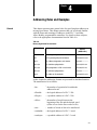
Addressing Rules and Examples . . . . . . . . . . . . . . . . . . . .
41
General . . . . . . . . . . . . . . . . . . . . . . . . . . . . . . . . . . . . . . . . . . .
Number Systems . . . . . . . . . . . . . . . . . . . . . . . . . . . . . . . . . . . .
Addresses . . . . . . . . . . . . . . . . . . . . . . . . . . . . . . . . . . . . . . . . .
Symbols . . . . . . . . . . . . . . . . . . . . . . . . . . . . . . . . . . . . . . . . . .
PLC-3 Address Specifications . . . . . . . . . . . . . . . . . . . . . . . . . .
PLC/PLC-2 Address Specifications . . . . . . . . . . . . . . . . . . . . . . .
Remote Station Address Specifications . . . . . . . . . . . . . . . . . . . .
Expression . . . . . . . . . . . . . . . . . . . . . . . . . . . . . . . . . . . . . . . .
41
42
43
44
47
410
412
413
Editing . . . . . . . . . . . . . . . . . . . . . . . . . . . . . . . . . . . . . . . .
51
General . . . . . . . . . . . . . . . . . . . . . . . . . . . . . . . . . . . . . . . . . . .
Editing the Message Instruction . . . . . . . . . . . . . . . . . . . . . . . . . .
Allocating Memory . . . . . . . . . . . . . . . . . . . . . . . . . . . . . . . . . . .
Editing Message Procedures . . . . . . . . . . . . . . . . . . . . . . . . . . .
51
51
52
52
ii
Table of Contents
Message Procedure Commands . . . . . . . . . . . . . . . . . . . .
61
General . . . . . . . . . . . . . . . . . . . . . . . . . . . . . . . . . . . . . . . . . . .
Assignment Command . . . . . . . . . . . . . . . . . . . . . . . . . . . . . . . .
CREATE Command . . . . . . . . . . . . . . . . . . . . . . . . . . . . . . . . . .
DELETE Command . . . . . . . . . . . . . . . . . . . . . . . . . . . . . . . . . .
Execute . . . . . . . . . . . . . . . . . . . . . . . . . . . . . . . . . . . . . . . . . .
EXIT Command . . . . . . . . . . . . . . . . . . . . . . . . . . . . . . . . . . . . .
GOTO Command . . . . . . . . . . . . . . . . . . . . . . . . . . . . . . . . . . . .
IF Command . . . . . . . . . . . . . . . . . . . . . . . . . . . . . . . . . . . . . . .
ON_ERROR Command . . . . . . . . . . . . . . . . . . . . . . . . . . . . . . .
STOP Command . . . . . . . . . . . . . . . . . . . . . . . . . . . . . . . . . . . .
Functions . . . . . . . . . . . . . . . . . . . . . . . . . . . . . . . . . . . . . . . . .
Comments . . . . . . . . . . . . . . . . . . . . . . . . . . . . . . . . . . . . . . . . .
61
62
65
65
66
66
67
67
68
69
69
611
Error Reporting . . . . . . . . . . . . . . . . . . . . . . . . . . . . . . . . .
71
General . . . . . . . . . . . . . . . . . . . . . . . . . . . . . . . . . . . . . . . . . . .
Reporting Error Codes . . . . . . . . . . . . . . . . . . . . . . . . . . . . . . . .
Recovery from Errors . . . . . . . . . . . . . . . . . . . . . . . . . . . . . . . . .
Error Monitoring . . . . . . . . . . . . . . . . . . . . . . . . . . . . . . . . . . . . .
71
71
71
72
Programming Examples . . . . . . . . . . . . . . . . . . . . . . . . . . .
81
General . . . . . . . . . . . . . . . . . . . . . . . . . . . . . . . . . . . . . . . . . . .
Individual Commands . . . . . . . . . . . . . . . . . . . . . . . . . . . . . . . . .
Message Procedure . . . . . . . . . . . . . . . . . . . . . . . . . . . . . . . . . .
81
81
84
Computer to PC Communication . . . . . . . . . . . . . . . . . . . .
91
Introduction to Layered Communication . . . . . . . . . . . . . . . . . . . .
Full-Duplex vs Half-Duplex Protocol for the Data Link Layer . . . . .
91
95
Full-Duplex Protocol . . . . . . . . . . . . . . . . . . . . . . . . . . . . .
101
General . . . . . . . . . . . . . . . . . . . . . . . . . . . . . . . . . . . . . . . . . . .
Definition of Link and Protocol . . . . . . . . . . . . . . . . . . . . . . . . . . .
Full-Duplex Protocol . . . . . . . . . . . . . . . . . . . . . . . . . . . . . . . . .
101
101
102
Half-Duplex Protocol . . . . . . . . . . . . . . . . . . . . . . . . . . . . .
111
Half-Duplex Protocol . . . . . . . . . . . . . . . . . . . . . . . . . . . . . . . . .
Multidrop Link . . . . . . . . . . . . . . . . . . . . . . . . . . . . . . . . . . . . . .
Transmission Codes . . . . . . . . . . . . . . . . . . . . . . . . . . . . . . . . . .
Link-Layer Packets . . . . . . . . . . . . . . . . . . . . . . . . . . . . . . . . . .
Protocol Environment Definition . . . . . . . . . . . . . . . . . . . . . . . . . .
Half-Duplex Protocol Diagrams . . . . . . . . . . . . . . . . . . . . . . . . . .
Line Monitoring . . . . . . . . . . . . . . . . . . . . . . . . . . . . . . . . . . . . .
111
111
112
114
117
1113
1120
Table of Contents
iii
The Network and Application Layer Protocol . . . . . . . . . . .
121
Network Layer . . . . . . . . . . . . . . . . . . . . . . . . . . . . . . . . . . . . . .
Application Layer . . . . . . . . . . . . . . . . . . . . . . . . . . . . . . . . . . . .
121
126
Message Formats . . . . . . . . . . . . . . . . . . . . . . . . . . . . . . .
A1
Introduction . . . . . . . . . . . . . . . . . . . . . . . . . . . . . . . . . . . . . . . .
Basic Command Set . . . . . . . . . . . . . . . . . . . . . . . . . . . . . . . . . .
PLC-3 Commands . . . . . . . . . . . . . . . . . . . . . . . . . . . . . . . . . . .
Privileged Commands . . . . . . . . . . . . . . . . . . . . . . . . . . . . . . . .
A1
A8
A13
A20
Error Codes . . . . . . . . . . . . . . . . . . . . . . . . . . . . . . . . . . . .
B1
General . . . . . . . . . . . . . . . . . . . . . . . . . . . . . . . . . . . . . . . . . . .
Local Error Codes . . . . . . . . . . . . . . . . . . . . . . . . . . . . . . . . . . .
Reply Error Codes . . . . . . . . . . . . . . . . . . . . . . . . . . . . . . . . . . .
Remote Error Codes . . . . . . . . . . . . . . . . . . . . . . . . . . . . . . . . .
Local and Reply Error Codes . . . . . . . . . . . . . . . . . . . . . . . . . . .
Remote Error codes received from the 1771-KE/KF, 1771-KG,
1771-KA, and 1774-KA Modules . . . . . . . . . . . . . . . . . . . . . .
Remote Error Codes Received from the 1773-KA Module . . . . . . .
B1
B1
B1
B3
B4
B14
B15
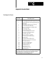
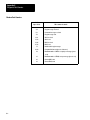
Diagnostic Counter Block . . . . . . . . . . . . . . . . . . . . . . . . .
C1
Data Highway Port Counters . . . . . . . . . . . . . . . . . . . . . . . . . . . .
Modem Port Counters . . . . . . . . . . . . . . . . . . . . . . . . . . . . . . . .
C1
C2
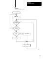
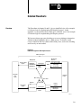
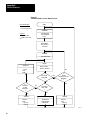
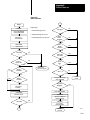
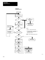
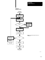
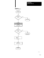
Detailed Flowcharts . . . . . . . . . . . . . . . . . . . . . . . . . . . . . .
D1
Overview . . . . . . . . . . . . . . . . . . . . . . . . . . . . . . . . . . . . . . . . . .
UART Sharing . . . . . . . . . . . . . . . . . . . . . . . . . . . . . . . . . . . . . .
SLEEP and WAKEUP . . . . . . . . . . . . . . . . . . . . . . . . . . . . . . . .
POWERUP . . . . . . . . . . . . . . . . . . . . . . . . . . . . . . . . . . . . . . . .
D1
D10
D17
D18
Chapter
1
Introduction
General
About This Manual
The PLC–3 Communication Adapter Module (cat. no. 1775–KA) is an
optional module used in the PLC–3 main chassis or expander chassis. It
serves two purposes:
1.
Interfacing the PLC–3 processor with the Allen–Bradley Data
Highway
2.
Interfacing the PLC–3 processor with an intelligent RS–232–C
device
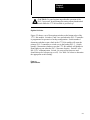
This manual describes the installation, programming, and operation of the
1775– KA module. This manual assumes that you are already thoroughly
familiar with the programming and operation of the PLC–3 processor. It
does not assume that you have any prior knowledge of the Allen–Bradley
Data Highway.
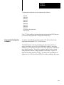
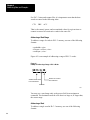
Organization
The remaining chapters of this manual are organized as follows:
Chapter 2 – describes installation of the 1775–KA module.
Chapter 3 – presents concepts and terminology for operating the
1775–KA module on the Data Highway.
Chapter 4 – presents general rules for specifying the data addresses you
use in message procedures.
Chapter 5 – explains how you create and edit message procedures and
commands for the 1775–KA module.
Chapter 6 – describes the command language you use in programming
message procedures.
Chapter 7 – describes how the 1775–KA module detects and reports
various types of errors.
Chapter 8 – presents detailed examples of 1775–KA module commands
and message procedures.
Chapter 9 – introduces a layered approach to writing a driver to enable
a computer to communicate to the 1775–K’s RS–232–C channel.
11
Chapter 1
Introduction
Chapter 10 – describes how to write a full–duplex line driver to enable
a computer to communicate to the 1775–KA’s RS–232–C channel.
Chapter 11 – describes how to write a half duplex line driver to enable
a computer to communicate to the 1775–KA’s RS–232–C channel.
Chapter 12 – describes the network and application layers of a software
driver to enable a computer to communicate to the 1775–KA’s
RS–232–C channel.
Appendix A – shows detailed message formats.
Appendix B – lists error codes reported by the 1775–KA, 1771–KA,
1771–KG, 1771– KE/KF, 1773–KA, and 1774–KA modules.
Appendix C – lists diagnostic counters stored at the 1775–KA,
1771–KA, 1771–KG, 1771–KE/KF, 1773–KA and 1774–KA modules.
Appendix D – gives detailed flow charts of an example of software
logic for implementing a full–duplex protocol.
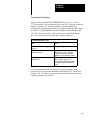
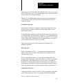
Related Documentation
Read this manual in conjunction with the documentation listed in
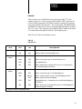
Table 1.A and Table 1.B. Table 1.A lists related PLC–3 documentation
and Table 1.B lists related Data Highway documentation.
Table 1.A
Related PLC-3 Documentation
Publication
Number
(Old/New No.)
12
Title
1775-800/1775-6.7.1
PLC-3 Installation and Operations Manual
1775-801/1775-6.4.1
PLC-3 Programming Manual
1775-806/1775-6.5.3
I/O Scanner-Message Handling Module User's
Manual
1775-900/1775-2.1
PLC-3 Controller Data Sheet
1775-901/1775-2.2
PLC-3 Main Processor Module Data Sheet
1775-902/--------
PLC-3 Memory Organization Data Sheet
1775-904/1775-2.4
Power Supply Data Sheet
1775-908/1775-2.6
PLC-3 Memory Modules Data Sheet
1775-910/1775-2.8
PLC-3 Main Chassis Data Sheet
Chapter 1
Introduction
Table 1.B
Related Data Highway Documentation
Publication
Number
(Old/New No.)
Title
1770-810/1770-6.2.1
Data Highway Cable Assembly and Installation Manual
1771-801/1771-6.5.1
Communication Adapter Module (cat. no. 1771-KA)
User's Manual
1771-802---------
Communication Controller Module (cat. no.1771-KC/KD)
User's Manual
1771-811/1771-6.5.8
PLC-2 Family/RS-232C Interface Module (cat.no.
1771-KG) User's Manual
1771/822/1771-6.5.15
Data Highway/RS-232-C Interface Module (cat. no.
1771-KE/KF) User's Manual
1773-801/1773-6.5.2
PLC-4 Communication Interface Module (cat. no.
1773-KA) User's Manual
1774-819/1774-6.5.8
Communication Adapter Module (cat. no. 1774-KA)
User's Manual
6001-800/6001-6.5.1
6001 NET (For VMS) Network Communications Software
User's Manual
6001-802/---------
6001 NET (For RSX-11) Network Communication
Software User's Manual
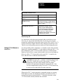
Terminology
In this manual you will read about the various commands the 1775–KA
module can send and/or receive. To distinguish between commands, we
use some of the following terms:
a protected command can read or write only specified areas of PC data
table. A switch on the PLC, PLC–2 Family, and PLC–4 Controllers
determines if the PC will accept only protected commands from another
PC or an RS–232–C device. When you use a protected command, you
may have a limited area that you can read or write in the other station’s
memory.
an unprotected command can read or write into any area of PC data
table. A switch on the PC that receives the commands determines if the
PLC, PLC–2 Family, and PLC–4 controller will accept unprotected
commands from another PC or an RS–232–C device.
privileged commands are sent by intelligent RS–232–C devices only.
Such devices include computers and intelligent terminals.
Allen–Bradley PC’s do not send privileged commands, but receive and
reply to them. A privileged command can read or write into any area in
the memory of a PC, whether or not switches on the PC have been set
to allow it to receive only protected commands. The term physical
13
Chapter 1
Introduction
command is sometimes used synonymously to mean privileged
command.
non–privileged commands include any command that both PC’s and
RS–232–C device can send. The non–privileged commands include the
protected write and unprotected read and write commands. The
non–privileged commands are also referred to as “PLC/PLC–2 type”
commands.
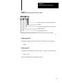
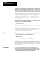
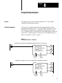
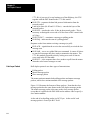
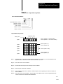
Module Description
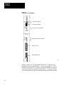
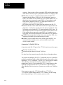
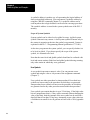
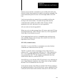
Figure 1.1 illustrates the front of the 1775–KA module. The module has
the following hardware features:
Self–test diagnostic indicators
Thumbwheel switch for setting identification number
Two ports– one for Data Highway and one for RS–232–C
communication
Two sets of indicators – one for each port
Switches for selecting fault responses and communication option
14
Chapter 1
Introduction
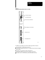
Figure 1.1
Communication Adapter Module (Cat. No. 1775-KA)
PASS
FAIL
SELF
TEST
NO
KA
XMTG
RCVG
ERR
DIS
MODEM
INTERFACE
Self–Test Indicators
Thumbwheel Switch
RS–232–C port Indicators
COMMUNICATION
ADAPTER
XMTG
RCVG
RDY
ERR
DIS
DATA
HWY
Data Highway Port Indicators
RS–232–C Port
Data Highway Port
DATA
HWY
10000-I
In addition, the module provides the following software features:
Programmable configuration parameters
Command language that allows for complex logic decisions, looping,
and nesting
Symbolic representation of data and addresses
Embedded arithmetic expressions and logic operations
Decimal, octal, or BCD (binary coded decimal) data entry
15
Chapter 1
Introduction
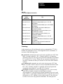
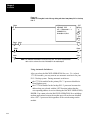
Specifications
Table 1.C lists the specifications for the 1775–KA module.
Table 1.C
Module Specifications
Function
Location
Interface the PLC-3 Processor
with the Allen-Bradley Data
Highway and/or with an RS-232-C
device
Single slot in PLC-3 main chassis
or expander chassis
Communication Ports
Data Highway
Communication Rate
To Data Highway - 57.6 kilobaud
recommended
To modem-programmable from 110
baud to 19.2 kilobaud
Cabling
To Data Highway-Data Highway
dropline cable (Cat.no.1770-CD or
equivalent
Backplane Power Requirement
2.5A max. @ +5V DC
Ambient Temperature Rating
00 o 600C (operational)
-400 to 850C (storage)
Humidity Rating
5% to 95% (without condensation)
To modem-Modem interface cable
(cat. no. 1775-CKA or equivalent)
RS-232-C Modem
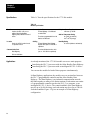
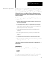
Applications
As already mentioned, the 1775–KA module serves two main purposes:
Interfacing the PLC–3 processor with the Allen–Bradley Data Highway
Interfacing the PLC–3 processor with an intelligent RS–232–C device
You can use the module for both of these purposes simultaneously.
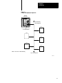
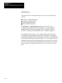
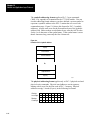
In Data Highway applications, the module serves as an interface between
the PLC–3 programmable controller and the Allen–Bradley Data
Highway. The Data Highway is an industrial communication network
that links together as many as 64 distinct stations. Each station can consist
of a programmable controller (such as the PLC–3), a computer, or an
intelligent RS–232–C device. The central trunkline of the Data Highway
may be up to 10,000 feet long, and each station may be as far as 100 feet
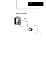
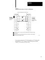
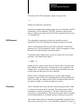
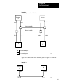
from the trunkline. Figure 1.2 gives an example of a Data Highway
configuration.
16
Chapter 1
Introduction
Figure 1.2
Example Data Highway Configuration
PLC-3
Controller
Allen-Bradley
Data Highway
PC
1775-KA Module
PC
PC
PC
PC
NOTE: All PCs are Allen-Bradley
Up to 64 Stations
10001–I
17
Chapter 1
Introduction
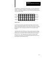
The PLC–3 can support multiple 1775–KA modules in the same PLC–3
chassis. This provides the PLC–3 with concurrent access to several
independent Data Highways.
The 1775–KA module can also serve as an interface between the PLC–3
programmable controller and an intelligent RS–232–C compatible device
or any Allen–Bradley PC and its Data Highway module. Some examples
of this application of the module are the following:
Interfacing two PLC–3 controllers through a modem link
Interfacing a PLC–3 controller with a computer (either directly or
through modems)
Interfacing a PLC–3 controller with a remote Data Highway through a
modem link
Interfacing a PLC–3 controller as a slave station on a multipoint
modem link
Interfacing a PLC–3 controller on a point–to–point link with PLC–2
Family processor through a 1771–KG module (The 1772–LR processor
is not supported in this configuration.)
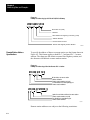
Figure 1.3 shows the 1775–KA module in a typical modem application.
Figure 1.3
Typical Modem Application
PLC-3
Controller
Modem
Computer
1775-KA Module
Modem
NOTE: Modems required
only
for distances greater
than 50 feet.
18
10002–I
Chapter
2
Installation
General
This chapter describes installation of the 1775–KA module in two phases:
Installing hardware
Programming configuration parameters through the PLC–3 LIST
function
Please read the entire manual carefully before attempting to install the
module.
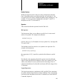
Hardware Installation
For best results when installing the 1775–KA module, proceed in the
order indicated below.
Switch Settings
The 1775–KA module has a number of hardware switches that must be set
before the module can be installed in the PLC–3 processor. There is a
thumbwheel switch on the front edge of the module and a group of option
switches on the bottom edge.
Thumbwheel Switch
Figure 2.1 shows a thumbwheel switch on the front edge of the 1775–KA
module. This thumbwheel switch designates the number used by the
PLC–3 processor to distinguish one 1775–KA module from another.
Rotate the thumbwheel to select the desired identification number.
21
Chapter 2
Installation
Figure 2.1
Front View of 1775-KA Module
PASS
FAIL
SELF
TEST
NO
KA
XMTG
RCVG
ERR
DIS
MODEM
INTERFACE
Self–Test Indicators
Thumbwheel Switch
RS–232–C port Indicators
COMMUNICATION
ADAPTER
XMTG
RCVG
RDY
ERR
DIS
DATA
HWY
Data Highway Port Indicators
RS–232–C Port
Data Highway Port
DATA
HWY
10003-I
If there is only one 1775–KA module in the PLC–3 chassis, set its
thumbwheel switch to the number 1. If there are multiple 1775–KA
modules in the same PLC–3 chassis, set their thumbwheel switches to
consecutive numbers, starting with the number 1. You may write the
selected number in the space provided beside the thumbwheel switch.
22
Chapter 2
Installation
CAUTION: To guard against unpredictable operation of the
PLC–3 processor, do not change the setting on any thumbwheel
switch while the 1775–KA module is powered–up.
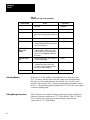
Option Switches
Figure 2.2 shows a set of four option switches on the bottom edge of the
1775– KA module. Switches 1 and 2 are used when the PLC–3 controller
is programmed to operate in a backup configuration. Switch number 1
determines whether or not a fault in the 1775–KA module will cause the
primary PLC–3 controller to switch over to the backup PLC–3. Switch
number 2 determines whether or not the 1775–KA module will disable its
Data Highway port when the PLC–3 becomes deactive. Switch 3 is for
RS–232–C communication. Switch 4 is reserved for future use and
should always be left open (up, or off). Use Table 2.A below to determine
the appropriate switch setting:
Figure 2.2
Option Switches
23
Chapter 2
Installation
Table 2.A
1775-KA Switch Settings
If this
switch:
Is:
1
OPEN
Then
the PLC will switch over to backup whenever one of the
following fault conditions occurs:
1. The 1775-KA module tries to hold control of the PLC-3
backplane for more than 138 microseconds.
2. The 1775-KA module experiences a execution timeout of
more than 32 milliseconds
3. The 1775-KA module experiences an internal stack
overflow
4. The 1775-KA module experiences severe Data Highway
communication problems.
1
CLOSED
the primary PLC-3 will not switch to backup when a fault occurs
with the 1775-KA module.
2
OPEN
the 1775-KA module will disable is Data Highway port
whenever the primary PLC-3 controller becomes deactive. The
module will no longer be able to transmit or receivemessages
through its Data Highway port.
Also, setting switch 2 to open enables the backup operation
feature.
2
CLOSED
the Data Highway port on the module will remain active if the
primary PLC-3 becomes deactive.
3
OPEN
the module may be connected up to 7,000 cable feet away from
a 1771-KF, a 1771-KG, 1773-KA or another 1775-KA module.
In addition to setting switch 3 to the open position, you must
also set switch 2 to closed position. This makes pin 25 on the
RS-232-C port of the 1775-KA module active (refer to figures
2.8 to 2.10). Note that switch 3 must always be closed for
communication with an RS-232-C device other than a
1771-KF, 1771-KG, 1773-KA, or 1775-KA module.
3
CLOSED
the MODEM INTERFACE port of the 1775-KA module may be
connected to a standard RS-232-C device that is located within
50 cable feet of the module.
4
OPEN
Switch 4 is reserved for future use and should always be left
open.
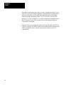
Module Placement
After setting the thumbwheel switch, insert the module into any one of the
module slots in the PLC–3 processor chassis. Whenever you power–up
the processor, the module will receive power also.
24
Chapter 2
Installation
Indicators
There are three sets of LED indicators on the front of the 1775–KA
module (Figure 2.1). The first group, labeled SELF–TEST, indicates the
result of internal diagnostic tests that the module continuously performs
on its own hardware and firmware. The second group, labeled MODEM
INTERFACE, indicates the status of communication through the module’s
RS–232–C port. The last group, labeled DATA HWY, indicates the status
of communication through the module’s Data Highway port.
Table 2.B. tells what each indicator means.
Table 2.B
LED Indicators
Indicator
Group
Indicator
Label
Normal
State
Self-Test
PASS
ON
Module has passed its own internal diagnostic test
FAIL
OFF
Module has failed its own internal diagnostic tests
XMTG
OFF
Module is transmitting a message over the modem interface port
RCVG
OFF
Module is receiving a message over the modem interface port.
ERR
OFF
User programming error
DIS
OFF
Module is disabled due to a fault in the PLC-3 processor, or modem interface
port is disabled through the LIST function
XMTG
OFF
Module is transmitting a message over the Data Highway port
RCVG
OFF
Module is receiving a message over the Data Highway port
RDY
ON or [1]
OFF
ERR
OFF
User programming error or communication error on either the Data Highway or
the Modem port
DIS
OFF
Module is disabled due to a fault in the PLC-3 processor, or Data Highway port
is disabled through the LIST function
Modem
Interface
Data
Highway
Meaning When ON
Module is ready to transmit a message over the Data Highway port and is
waiting to acquire mastership of the highway
[1] Depends on amount of data highway activity
25
Chapter 2
Installation
Data Highway Cable Connections
There are two cable connectors, or ports, on the front of the 1775–KA
module (Figure 2.1). The bottom port, labeled DATA HWY., is for
connection to the Allen–Bradley Data Highway. If you are using the
1775–KA module in a Data Highway application, plug the Data Highway
dropline cable into this port. For details on the installation of the Data
Highway cable, refer to the Data Highway Cable Assembly and
Installation Manual (publication 1770–810).
RS-232-C Cable Connections
The RS–232–C port, labeled MODEM INTERFACE on the 1775–KA
module, can interface with any RS–232–C device that is capable of
understanding and generating the communication protocol described in
this chapter. Some typical RS–232–C applications are:
Interfacing two PLC–3 controllers through a modem link (Figure 2.3)
Figure 2.3
Linking Two PLC-3 Controllers
PLC-3 Controller
Modem
1775-KA Module
PLC-3 Controller
Modem
NOTE: Modems required only
for distances greater
than 50 feet.
1775-KA Module
26
10004–I
Chapter 2
Installation
Interfacing a PLC–3 controller with a computer, either directly or
through modems (Figure 2.4)
Figure 2.4
Linking a PLC-3 Station to a Computer
PLC-3
Controller
Modem
Computer
1775-KA Module
Modem
10005–I
27
Chapter 2
Installation
Interfacing a PLC–3 controller with a remote Data Highway through a
modem link (Figure 2.5)
Figure 2.5
Linking a PLC-3 Station to a Remote Data Highway
PLC-3
Controller
Modem
1775-KA Module
Modem
Allen-Bradley
Data Highway
1771-KF Module
PC
PC
PC
NOTE: All PCs are Allen-Bradley
PC
PC
Up to 64 Stations
28
10006–I
Chapter 2
Installation
Interfacing a PLC–3 controller to a PLC–2 Family processor through a
1771–KG module in a point–to–point link (Figure 2.6)
Figure 2.6
Linking a PLC-3 to PLC-2 Family Controller
PLC–3 Controller
Modem
1775–KA Module
PLC–2 Controller
Modem
1771–KG Module
NOTE: Modems required only for
distances greater than 50 feet.
10007-I
29
Chapter 2
Installation
Interfacing a PLC–3 controller as a slave station on a multipoint
modem link (Figure 2.7)
Figure 2.7
Linking a PLC-3 to a Multi-drop Modem Link
Computer
Multidrop Modem
Master Station
Multidrop Modem Link
PLC-3 Controller
Modem
1775-KA Module
10008–I
Slave Stations
The first four applications above use the module’s RS–232–C port in the
unpolled mode, while the last application uses the polled mode. You can
select the mode of operation and other characteristics of the RS–232–C
port through the LIST function.
210
Chapter 2
Installation
Each mode of operation requires a different communication protocol. The
unpolled mode uses full–duplex protocol (chapter 10) while the polled
mode uses half–duplex protocol (chapter 11). In general, full–duplex
protocol gives faster data throughput but is more difficult to implement;
half–duplex protocol is easier to implement but gives slow data
throughput.
NOTE: In other Data Highway documentation, full–duplex protocol
might be referred to as DFI protocol, and half–duplex protocol might be
referred to as polled–mode protocol.
Hardware Interface
The modem interface is based on EIA RS–232–C and related standards.
This interface should be compatible with most dedicated and dial–up
network RS–232 modems.
Mechanical
The RS–232 connector on the 1775–KA module is a 25–pin male
connector.
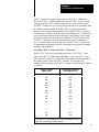
Electrical
Input and output levels on the RS–232 connector conform to the
RS–232–C standard. The transmitter has increased capability to drive a
7,000 foot isolated lines. This number depends on baud rate and refers to
only direct wire connections. (Refer to Table 2.C.)
211
Chapter 2
Installation
Table 2.C
Distance Rate Variations
Distance
in feet
Maximum
Baud Rate
1,000
19,200
2,000
9,600
3,000
9,600
4,000
4,800
5,000
4,800
6,000
2,400
7,000
2,400
The receiver is designed to sense the signal generated by a similar
transmitter, and is electrically isolated from all other circuitry on the
module. It consists of an opto–isolater circuit with an input and return
connection at the RS–232 connector. All other signals on the RS–232
connector are driven and received by standard RS–232 interface circuits,
and have a maximum drive capability of 50 feet.
212
Chapter 2
Installation
Pinout
The necessary RS–232–C port connections are described in Table 2.D
below:
Table 2.D
RS-232-C Port Connections
Signal at the
1775-KA
Abbreviation
chassis/shield drain
Pin
Input/Output
1
transmitted data
TXD
2
Output
received data
RXD
3
Input
request to send
RTS
4
Output
clear to send
CTS
5
Input
data set ready
DSR
6
Input
transmitted data return
TXDRET
7/14
data carrier detect
DCD
8
Input
data terminal ready
DTR
20/11
Output
received data return
RXDRET
25/13
TXD (transmitted data) caries serialized data. It is output from the
RS–232 connector.
RXD (received data) is serialized data input to the RS–232 connector.
RXD and RXDRET are isolated from the rest of the circuitry on the
module.
RTS (request to send) is a request from the RS–232 connector to the
modem to prepare to transmit. It typically turns the data carrier on.
When you select the full duplex mode RTS is always asserted. When
you select the half duplex mode RTS is turned on when the module has
permission to transmit; otherwise it is off.
CTS (clear to send) is a signal from the modem to the RS–232
connector that the carrier is stable and the modem is ready to transmit.
The module will not transmit until CTS is true. If CTS is turned off
during transmission, the module will stop sending until CTS is restored.
DTR (data terminal ready) is a signal from the RS–232 connector to the
modem to connect to the phone line (that is, “pick up the phone”). The
module will assert DTR all the time except during the phone hangup
213
Chapter 2
Installation
sequence. Some modem will not respond to DTR until the phone rings,
while others will always pick up the phone whether it is ringing or not.
DSR (data set ready) is a signal from the modem to the RS–232
connector that the phone is off–hook. (It is the modem’s answer to
DTR). The module will not transmit or receive unless DSR is true. If
the modem does not properly control DSR, or if no modem is used,
DSR must be jumpered to an RS–232 high signal at the RS–232
connector. (It can be jumpered to DTR).
DCD (data clear ready) is a signal from the modem to the RS–232
connector that the carrier from another modem is being sensed on the
phone line. It will not be asserted unless the phone is off–hook. Data
will not be received at the RS– 232 connector unless DCD is true. In
the full duplex mode the module will not transmit unless DCD is true.
If the modem does not properly control DCD, or if a modem is not
being used, DCD must be jumpered to DTR at the RS–232 connector.
TXDRET (transmitted data return) is the return signal for TXD. It is
connected to module logic ground through a resistor.
RXDRET (received data return) is the return signal for RXD. It is
connected to the isolated receiver, and is isolated from all other
circuitry on the module.
Connections To The RS–232 Port
Connection to the RS–232 port of the 1775–KA can be one of two types:
Short line (50 feet or less)
Isolated long line (between 50 and 7,000 feet)
For short lines, the connection may be either direct or through modems.
You connect an intelligent, RS–232–C compatible device to an interface
module by attaching a cable to both the device and to the module socket
labeled RS– 232–C CHANNEL. The RS–232–C device may be another
Allen–Bradley communication interface module or another
manufacturer’s device. For a standard RS–232–C connection, the cable
should be no longer than 50 feet. If your RS–232–C device has an
Allen–Bradley line driver/receiver, you may use a cable up to 7,000 feet
long.
If you want to connect the 1775–KA module to a 1771–KG or
1771–KE/KF module through the RS–232–C channel, use the cabling
pinout diagram (Figure 2.8) to construct your own cable.
214
Chapter 2
Installation
Figure 2.8
Connection to Allen-Bradley 1771-KG or 1771-KE/KF Module
Connect the Shield at One End Only
1
RS–232–C
CHANNEL
Connector
of 1775–KA
Module
1
1
2
3
7
13
3
2
25
14
4
4
5
5
6
6
8
8
20
11
2
RS–232–C
CHANNEL
Connector
of 1771–KG
or 1771–KE/KF
Module
1
Conductors 2 and 7, 3 and 25 must be twisted pairs for distances longer
than 50 feet.
2
Set switch 3 (on the 1775–KA) OFF when the module is communicating
with another Allen-Bradley device.
10009–I
If you want to connect the 1775–KA module to a 1775–KA module
through the RS– 232–C channel, use the cabling pinout diagram
(Figure 2.9) to construct your own cable.
215
Chapter 2
Installation
Figure 2.9
Connection to Allen-Bradley 1775-KA Module
Connect the Shield at One End Only
1
RS–232–C
CHANNEL
Connector
of 1775–KA
Module
2
1
1
2
3
7
25
3
2
25
7
4
4
5
5
6
6
8
8
20
20
RS–232–C
CHANNEL
Connector
of 1771–KA
Module
1
Conductors 2 and 7, 3 and 25 must be twisted pairs for distances longer
than 50 feet.
2
Set switch 3 (on the 1775–KA) OFF when the module is communicating
with another Allen-Bradley device.
10010–I
If you want to connect the 1775–KA module to a modem or computer, use
the cabling pinout diagram (Figure 2.10) to construct your own cable.
216
Chapter 2
Installation
Figure 2.10
Connection to user-Supplied Modem or RS-232-C Device
RS–232–C 1
CHANNEL Connector of
1775–KA Module
1
Protective Ground
1
Transmitted Data
2
Received Data
3
Request to Send
4
Clear to Send
5
Data Set Ready
6
Signal Ground
7
Line Signal Detect
8
Data Terminal Ready
20
Received Data
Return
25
Set Switch 3 ON to ground pin 25.
User–supplied
Moderm or
RS–232–C
Device
10011–I
Private lines are permanently connected phone lines used with modems.
Dialup is not needed. Usually the modem hold the handshake lines in the
proper states.
The RS–232 port can be connected to standard American dial–up modems
and some European modems. Other European standards specify that the
DTR signal will cause the modem to answer the phone whether it is
ringing or not, causing the phone to always be “busy”. Since the modem
port asserts DTR while waiting for a call, it cannot be used with such
modems.
The types of dial–up network modems that can be used are classified into
the following types:
Manual: these are typically acoustically coupled modems. The
connection is established by human operators at both ends, who then
insert the handset into couplers to connect the computers.
DTE–controlled answer: these unattended modems are directly
connected to the phone lines. A module controls the modem via the
217
Chapter 2
Installation
DTR, DSR, and DCD signals. It incorporates timeouts and tests to
properly operate these types of modems.
Auto–answer: these modems have self–contained timeouts and tests,
and can answer and hangup the phone automatically.
The modem port has no means to control an auto–dial modem, although it
is possible that it can be used in conjunction with a separate auto–dialer.
Answering
The module continually asserts DTR when it is waiting for a call. Under
this condition the modem will answer a call and assert DSR as soon as
ringing is detected. The module does not monitor the RING indicator in
the RS–232 interface. Once DSR is detected the module starts a timer
(around 10 seconds) and waits for the DCD signal. When DCD is
detected communication can start.
If DCD is not detected within the timeout, the module turns DTR off. This
causes the modem to hangup and break the connection. When the hangup
is complete the modem drops the DSR line. This causes the module to
reassert the DTR line and wait for another call. This feature protects
access to the phone if someone calling a wrong number reaches this
station.
Once DCD is detected the module continues to monitor the DCD line. If
DCD goes false the timeout is restarted. If DCD is not restored within the
timeout, the hangup sequence is initiated. This feature allows the remote
station to re–dial in the event the connection is lost by the phone network.
Note that this handshaking is necessary to guarantee access to the phone
line. If this handshaking protocol is defeated by improper selection of
modem options, or jumpers at the connectors, the modem may answer a
call, but if the connection is lost the modem will not hangup. It will be
impossible for the remote station to reestablish the connection because it
will get a busy signal.
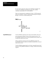
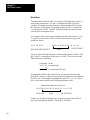
Character Transmission
Data is sent serially over the RS–232 interface, one eight–bit byte at a
time. The transmission format conforms to ANSI X3.16, CCITT V.4, and
ISO 1177, with the exception that the parity bit is retained while
extending the data length to eight bits.
218
Chapter 2
Installation
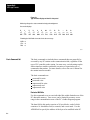
The transmission format may be summarized as follows:
start bit
data bit 0
data bit 1
data bit 2
data bit 3
data bit 4
data bit 5
data bit 6
data bit 7
even parity bit (optional)
one stop bit
The 1775–KA module selects baud and parity through the LIST function
(section titled Programmable Configuration Parameters).
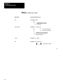
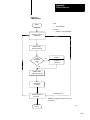
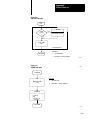
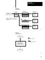
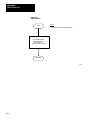
Programmable Configuration
Parameters
A number of installation parameters for the 1775–KA module can be
programmed through the PLC–3 LIST function.
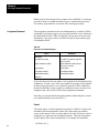
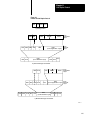
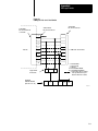
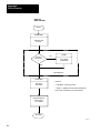
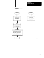
The LIST function words by presenting you with a series of lists, or
menus, that allows you to select and establish the module’s operating
parameters. Each option in an upper–level menu represents a submenu of
more detailed options. This process continues until you have selected
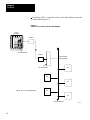
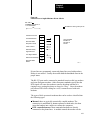
enough options to define a single parameter in full detail. Figure 2.11
illustrates the menu structure of LIST. To return to the preceding (next
highest) level of LIST, press the ENTER key without making a new entry.
219
Chapter 2
Installation
Figure 2.11
LIST Menu for 1775-KA Module
System Mode
1 Test–Monitor
2 Run Monitor
3 Program Load
4 Remote Enable
5 System Status
6 *Module Status
Enter Next >
Modules
1 01 1775–ME8 A/A
2 02 1775–ME8 A/A
3 03 1775–L3 A/A
4 04 1775–S4A B/A
5 05 1775–KA A/E
6 06 1775–LX A/A
7 07 1775–LX A/A
8 08 1775–S4B B/A
9 09 1775–S4B B/A
ENTER NEXT >
Data Hwy Comm
Adapter – 01
Chassis 0 Slot 0
1 Module Options
2 Data Highway Port
3 Modem Port
Enter Next >
KA–01 Module Options
1 Timeout
1
2 *Send Unprotected
1
3 Accept Upload/Download
4 Accept Writes1
KA–01 Module Options
Timeout = 50/10 sec
Enter Timeout >
5 Backup Operation
1
6 PLC–2 Mask1
ENTER NEXT >
KA–01 Data Highway Port
1 Enable/Disable Port
2 Station Number
3 Baud Rate
Enter Next >
KA–01 Data Highway Port Enable
1 Enable
2 *Disable
Enter Next >
KA–01 Data Highway Port
Station Number
= 377
Enter Station Number >
KA–01 Data Highway Port Baud Rate
1 38400
2 *57600
Enter Next >
KA–01 Modem Port
1 Enable/Disable Port
2 Station Number
3 Baud Rate
4 Communication Mode
5 Even Parity1
6 *Send Embedded
Responses1
Enter Next >
1
Toggle selection – select this number to enable
or disable the option.
NOTE: Those selections shown in bold type affect
the operation of the module; the LIST display
shows an asterisk (*) to indicate when an
option is enabled. The selections not shown in
bold type only cause a movement to another level
of LIST. This selections indicated in this figure are
selected by default at the initial power–up.
KA–01 Modem Port Enable
1 Enable
2 *Disable
Enter Next >
KA–01 Modem Port
Station – 377
Enter Station Number >
KA–01 Modem Port Baud Rate
1 110
2 300
3 600
4 *1200
5 2400
6 4800
7 9600
8 19200
Enter Next >
KA–01 Modem Port Communication Mode
1 *Unpolled Mode
2 Polled – Subscriber Mode
Enter Next >
10012–I
220
Chapter 2
Installation
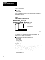
You access the LIST function by typing the word LIST and press the
ENTER key. After accessing the LIST function, select option 6 MODULE
STATUS from the SYSTEM–MODE MENU. LIST then presents you
with a menu that describes the modules in your system. The menu varies
according to the modules in your PLC–3. A typical menu might be:
MODULES:
1 01 1775–ME8 A/A
2 02 1775–ME8 A/A
3 03 1775–L3 A/A
4 04 1775–S4A B/A
5 05 1775–KA A/E
6 06 1775–LX A/A
7 07 1775–LX A/A
8 08 1775–S4B B/A
9 09 1775–S4B B/A
ENTER NEXT<
Under MODULE STATUS, select the option for 1775–KA. At this point,
LIST presents you with the following menu for the 1775–KA module:
DATA HWY COMM. ADAPTER–nn
CHASSIS cc SLOT ss
1 MODULE OPTIONS
2 DATA HIGHWAY PORT
3 MODEM PORT
ENTER NEXT>
In the above and all following menus, “nn” represents the thumbwheel
setting of the 1775–KA module, “cc” represents the chassis number, and
“ss” represents the number of the chassis slot containing the module. For
more information about the LIST function, refer to Publication 1775–800,
PLC–3 Installation and Operation Manual.
Module Options
Selecting option 1 MODULE OPTIONS from the above menu (section
titled Programmable Configuration Parameters) causes LIST to present
the following menu:
KA – nn MODULE OPTIONS
1 TIMEOUT
2 SEND UNPROTECTED
221
Chapter 2
Installation
3 ACCEPT UPLOAD/DOWNLOAD
4 ACCEPT WRITES
5 BACKUP OPERATION
6 PLC–2 MASK
ENTER NEXT>
This menu allows you to select options that apply equally to both the
modem port and the Data Highway port of the 1775–KA module. These
options are described below.
Timeout
The timeout is the maximum amount of time that the 1775–KA module
will wait for another station to reply to one of its messages. The allowed
entries are 0 to 9999, expressed in increments of 1/10 second. LIST
displays the timeout as “xxxx/10 SEC”. Thus, if you enter a timeout
value of 100, the timeout period will be 10 seconds and will be displayed
as 100/10 SEC.
The same timeout setting applies to both the Data Highway and the
modem ports. The default timeout setting is 5 seconds, displayed as 50/10
SEC.
The timeout period applies to each individual transmission. Because of
their size, some messages consist of several packets of data. Each
message packet requires a separate transmission. Therefore, the timeout
is restarted for each packet.
If the 1775–KA module waits longer than the timeout period for a reply to
one of its messages, it generates an error code of 37 (Appendix B). The
module then resumes executing the current message procedure at the line
following the one in which the timeout occurred.
LIST keeps you at this timeout level and allows you to make repeated
changes to the timeout value. To return to the preceding (next highest)
level of LIST, press the ENTER key again without entering a new timeout
value.
222
Chapter 2
Installation
Send Unprotected
This option determines whether or not the 1775–KA module will be able
to send unprotected command messages to other stations. If you select
option 2 SEND UNPROTECTED, the 1775–KA module will be able to
send both protected and unprotected commands.
You can use an unprotected command to read or write to any area of a PC
data table. You can use a protected command, however, to write only to
those areas of a PC data table specified by the PC that receives the
command. For more information on protected and unprotected
commands, see section titled Access Privileges, chapter 3.
If you do not select (enable) this option, the module will be able to
transmit only protected commands. At initial power–up, the module
enables the SEND UNPROTECTED option by default.
Accept Upload/Download
This option determines whether or not the 1775–KA module will be able
to execute upload and download commands sent to it by a computer. If
option 3 ACCEPT UPLOAD/DOWNLOAD is selected, the module will
be able to execute both upload and download commands. You send a
sequence of upload and download commands when you want to transfer
the memory of the PLC–3 to another station, or to transfer the memory of
another station to a PLC–3.
If this option is not selected (enabled) the module will not be able to
execute either of these two types of commands. For a description of
upload and download commands, refer to Appendix A. At initial
power–up, the module enables the ACCEPT UPLOAD/DOWNLOAD
option by default.
Accept Writes
This option determines whether or not the 1775–KA module will accept
write–type command messages from a remote Data Highway station when
the local PLC–3 processor’s memory protect keyswitch is on. If option 4
ACCEPT WRITES is selected, the module will accept write commands
regardless of the setting of the PLC–3’s memory protect keyswitch. If
this option is not selected (enabled) the module will accept write
commands when the memory protect keyswitch is off but will reject the
write commands and return an error code of 86 if the memory protect
223
Chapter 2
Installation
keyswitch is on. At initial power–up, the module enables the ACCEPT
WRITES option by default.
Backup Operation
This option determines whether or not a pair of 1775–KA modules will
provide backup for each other. Enable option 5 (BACKUP OPERATION)
for both the primary and backup 1775–KA modules to enable backup
operation as described in section 2.3 (backup configurations). If you
make no selection for option 5, backup operation is disabled by default.
The revision C or earlier version of the module does not have the
BACKUP OPERATION option.
PLC–2 Mask
This option determines whether or not the 1775–KA module will mask
out the upper octal digit of the source address when receiving a PLC–2
type command from another station. If you enable option 6
(PLC–2–MASK) the module mask out the upper digit of the address for
selecting the input file. This causes stations with common second and
third digits of their address to access the same input file. For example,
stations 023, 123, 223, and 323 would all access input file 023.
If you disable option 6, each station accesses a unique input file with the
same number as the station number. For example, station 123 would
access input file 123; station 223 would access input file 223. If you
make no selection for option 6, the PLC–2 MASK option is disabled by
default. The revision D or earlier version of the module does not have the
PLC–2 MASK option.
Data Highway Port
Selecting option 2 DATA HIGHWAY PORT from the above menu
(section titled Programmable Configuration Parameters) causes LIST to
present the following menu:
KA – nn DATA HIGHWAY PORT
1 ENABLE/DISABLE PORT
2 STATION NUMBER
3 BAUD RATE
ENTER NEXT>
224
Chapter 2
Installation
This menu allows you to select options that apply to only the Data
Highway port of the 1775–KA module. These options are described
below.
Enable/Disable Port
This option determines whether or not the 1775–KA module can
communicate over the Data Highway. you must select the ENABLE
option in order to allow communication to take place. If you make no
selection, the PLC–3 disables this port by default.
Note, however, that you cannot use LIST to change any other parameters
of the Data Highway port unless you first DISABLE the port. After you
are done entering parameters through LIST, don’t forget to ENABLE the
Data Highway port again.
Station Number
This option selects the number by which the PLC–3 station is identified
on the Data Highway. Allowable station numbers are 1 to 376 octal. In
particular, note that the number 377 is illegal. Entering 377 as the station
number will automatically disable the 1775–KA module, and you will not
be able to ENABLE it again through LIST until you select a different
station number. If you make no selection, the PLC–3 assumes the illegal
address 377 by default.
Baud Rate
This option specifies the communication rate over the Data Highway. A
communication rate of 57,600 baud is recommended.
Modem Port
Selecting option 3 MODEM PORT from the above menu (section titled
Programmable Configuration Parameters) causes LIST to present the
following menu:
KA–NN modem port
1 ENABLE/DISABLE PORT
2 STATION NUMBER
3 BAUD RATE
4 COMMUNICATION MODE
225
Chapter 2
Installation
5 EVEN PARITY
6 SEND EMBEDDED RESPONSES
ENTER NEXT>
This menu allows you to select options that apply to only the modem port
of the 1775–KA module. These options are described below.
Enable/Disable Port
This option determines whether or not the 1775–KA module can
communicate through its RS–232–C port. You must select the ENABLE
option in order to allow this communication to take place. If you make no
selection, the PLC–3 disables the RS–232–C port by default.
Note, however, that you cannot use LIST to change any other parameters
of the RS–232–C port unless you first disable the port. After you are
done entering parameters through LIST, don’t forget to enable the
RS–232–C port again
Station Number
This option selects the number by which the PLC–3 station is identified
on an RS–232–C communication link. In particular, note that the number
377 is illegal. Entering 377 as the station number will automatically
disable the RS– 232–C port of the 1775–KA module, and you will not be
able to enable it again through LIST until you select a different station
number. If you make no selection, the station number will be 377 by
default.
Baud Rate
This option specifies the communication rate over the RS–232–C port.
The choices are:
110 baud
300 baud
600 baud
1200 baud
2400 baud
4800 baud
9600 baud
19200 baud
For long–line communication, the maximum allowed rate is 4800 baud.
The default baud rate is 1200 baud (see Table 2.D).
226
Chapter 2
Installation
Communication Mode
This option determines whether the RS–232–C port of the 1775–KA
module can operate in a half–duplex (polled) or full–duplex (unpolled)
mode. Select full– duplex for point–to–point communication through the
RS–232–C port. Select half–duplex if the 1775–KA module is installed
as a slave station on a multipoint modem link. If you make no selection,
the 1775–KA selects the full– duplex (unpolled) mode by default.
Even Parity
This option determines what kind of parity check is used for all
communications through the RS–232–C port. If option 5 EVEN PARITY
is selected, the 1775–KA module will test for even parity in all
communications through its RS–232–C port. If this option is not
selected, the module will not perform any parity checking. At power–up,
the PLC–3 disables the even parity option by default.
Send Embedded Responses
This option determines whether or not the 1775–KA module will be able
to send embedded responses through its RS–232–C port. Responses are
acknowledgments (ACKs or NAKs) to messages received from other
stations. An embedded response is one whose characters are transmitted
between the bytes of a regular message. In this way, the response to a
previously received message is transmitted along with a new message. At
power–up, the PLC–3 disables the embedded responses option by default.
Backup Configurations
The 1775–KA module can combine with the PLC–3 processor to form a
backup system. System backup is described in greater detail in the
PLC–3 Programmable Controller Backup Concepts Manual (pub. no.
1775–6.3.1). The following discussion is an overview of system backup
and the role of the 1775–KA in various backup procedures.
There are two possible backup configurations for the 1775–KA module:
Two 1775–KA modules in the same PLC–3 controller
One 1775–KA module in a primary PLC–3 controller and another
1775–KA in a backup PLC–3 controller
The first configuration provides backup for the 1775–KA module itself.
Here, both 1775–KA modules are always active, and both are independent
stations on their communication network. Therefore, each 1775–KA
227
Chapter 2
Installation
module must have its own unique station number. If you want to send the
same message through both 1775– KA modules, you must program the
two separate message instructions.
The second configuration provides system backup for the PLC–3
controller.
If the 1775–KA modules are Rev. C or earlier, you:
1.
Assign different station addresses to each communication adapter
module.
2.
If the programs in the primary and backup processors are identical:
you must be sure that all information sent to the primary processor is
also sent to the backup processor.
you must examine the run/backup bit (data table status section, file 0,
word 3, bit 17) on every rung used to transmit data. This bit is set in
the primary processor and reset in the backup processor. Examining it
helps to prevent sending duplicate messages over the Data Highway.
If the 1775–KA modules are Rev. D or later, you can:
follow the two steps described above
or
select BACKUP OPERATION with the PLC–3 LIST function.
To implement backup operation, follow these steps:
1.
Using the option switches on both 1775–KA modules, set switch 2 to
the OPEN position. Recall (section titled Option Switches) that this
causes the module to disable its Data Highway port if the PLC–3
becomes deactivated.
WARNING: If you do not set these switches OPEN on both
1775–KA modules, these modules will assume the same station
address when the primary PLC–3 becomes deactive. This may
shut down communication on the Data Highway, and
unexpected machine motion may result.
228
Chapter 2
Installation
2.
Use the LIST function to disable the modem and Data Highway
ports.
3.
Use the LIST function to select BACKUP OPERATION for both the
primary and backup 1775–KA modules. For more information, see
the PLC–3 Installation and Operation manual (publication
1775–6.7.1). Thus, when you select BACKUP OPERATION, the
condition appears like this:
5*BACKUP OPERATION
4.
Use the LIST function to assign the same station address to the
modules for the primary PLC–3 and the backup PLC–3 processor.
You can never give the 1775–KA module a station address of 3778,
and when you select the BACKUP OPERATION, you can not give
the module an address of 2778.
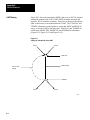
Because you have chosen BACKUP OPERATION, the module in the
backup PLC–3 will assume an address other than the address you
assign it with the LIST function (Figure 2.12).
You assign both modules an identical address.
If the address
is between:
The backup module assumes
an address that is:
0018 and 2768
1008 higher than the primary module
3008 and 3768
2008 lower than the primary module
At switchover, the address for the backup module returns to the
station address you assigned to it with the LIST function.
5.
Use the LIST function to enable whichever (Data Highway or
Modem) port you are using to connect primary to backup.
229
Chapter 2
Installation
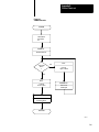
Figure 2.12
How addresses of the primary and backup PLC-3 controllers change during switchover.
Before switchover:
You set these
station addresses:
The module assume
the station addresses:
After switchover:
You previously set
these station addresses:
The module assume
the station addresses:
230
Primary PCL–3
Backup PLC–3
010
010
010
110
Backup PLC–3
Primary PCL–3
010
010
110
010
10013–I
Chapter 2
Installation
Using Manual Switchover
After you select the BACKUP OPERATION for a rev. D. (or later)
1775–KA module, you may choose to use your PLC–3 backup system for
manual switchover. In manual switchover, you must initiate the
switchover by changing the position of a switch in a backup cable. (Refer
to the PLC–3 Programmable Controller Backup Concepts Manual, pub.
1775–803, for more details.) You must be sure to turn off the faulted
PLC–3 processor before you begin the switchover, however.
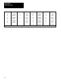
If a manual switchover occurs:
And:
Then:
the PLC-3 processor is waiting for a
response
the response is ignored
another station on the Data Highway is
initiating a message
you may not receive a response from
either PLC-3 processor. You must
program other stations on the Data
Highway to recover from this condition
you are only communicating with the
primary PLC-3
the other stations on the Data Highway
will receive time-out errors for
messages they send after the primary
goes deactive and before switchover
occurs.
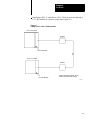
You can program the MSG instruction to execute a message upon
switchover or you can send commands to the backup PLC–3 processor
(Figure 2.13). As long as you get responses from the backup processor,
switchover has not yet occurred.
231
Chapter 2
Installation
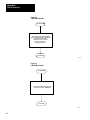
Figure 2.13
Example of a Rung that Sends a Message during switchover from primary PLC-3 to backup
PLC-3.
MSG
1
MESSAGE TYPE
CTL = FB200:00001 = 0
CHANNEL: E2.5.
#H045$N4:17= $B3:5
E0000
00
E0000 S0003
01
STAT
DN
15
STAT
ER
13
E0000
00
17
E0000
L
01
E0000
00
S0003
17
STAT
EN
12
NOTE: Bits E0000/00 and E0000/01 are internal storage bits. You can use any unused data
table section to reference these bits. Bit S0003/17 is the run/backup bit.
E0000
U
01
Using Automatic Switchover
After you select the BACKUP OPERATION for a rev. D. (or later)
1775–KA module, you may want to use automatic switchover for your
PLC–3 backup system. During automatic switchover:
the 1775–KA module for the primary PLC–3 processor disables its
Data Highway port.
the 1775–KA module for the backup PLC–3 processor becomes the
address that you selected with the LIST function (rather than the
corresponding address it received during the BACKUP OPERATION).
NOTE: You cannot select the BACKUP OPERATION for a multidrop
modem applications because the modem port will not become disabled
after a PLC–3 processor fault regardless of the switch settings on the
module.
232
Chapter 2
Installation
If an automatic switchover occurs:
And:
Then:
the PLC-3 processor is waiting for a
response
the response is ignored
another station on the Data Highway is
initiating a message
possibly neither of the PLC-3 processors will
respond to the message. You must program
other stations on the Data Highway to recover
from this condition
another station is communicating with
the primary PCL-3 processor
the other station will receive no indication that
a switchover has occurred. You can,
however, program a MSG instruction to
execute a message upon switchover (fig.
2.13) or send commands to the backup
PLC-3 processor. If you are able to
communicate with the backup, you know that
no switchover has occurred
Run/Backup Bit
It is important to alert the proper personnel when a switchover occurs.
One way you can provide such indication is by having your program
monitor the run/backup bit (data table status section, file 0, word 3, bit 17)
and turn on alarms or lights when the status changes from backup to run.
This bit is set in the primary processor and reset in the backup processor.
Multiple 1775-KA Modules in
One PLC-3
It is also possible to link a single PLC–3 controller to more than one Data
Highway by installing multiple 1775–KA modules in the same PLC–3. In
this configuration, each 1775–KA module connects to a different Data
Highway, and each has a unique station number on its associated highway.
However, all the 1775–KA modules in the same PLC–3 controller can
have either the same or different station numbers.
CAUTION: If such a PLC–3 station is communicating through
a PLC/PLC–2 buffer file and all of the stations’ 1775–KA
modules have the same station number, then all of these
modules will transfer data through the same buffer file. This
can cause unpredictable results if several 1775–KA modules try
to read or write to the buffer file at the same time.
When such a PLC–3 station transmits a command message to a remote
Data Highway station, the thumbwheel number specified in the PLC–3
message instruction (section titled PLC–3 Stations) determines which
1775–KA module actually transmits the command.
233
Chapter
3
Data Highway Communication
General
This chapter introduces some of the concepts and terminology involved
with operating the 1775–KA module of the Data Highway.
Some Terminology
The Allen Bradley Data Highway is a communication network for
industrial control applications. The Data Highway consists of a central
trunkline cable that may be up to 10,000 feet long. This cable can link
together as many as 64 distinct communication points (or nodes) called
stations.
Each station consists of some type of processor and a station interface
module. The station interface module enables the processor to
communicate with other stations on the Data Highway. The 1775–KA
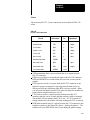
module is the station interface module for the PLC–3 processor. Table 3.A
lists all possible combinations of station interface modules and processors.
Table 3.A
Station Components
Processor
Station Interface Module
PLC-4 Microtrol
1773-KA Communication Interface Module
PLC-3
1775-KA Communication Adapter Module
PLC-2 Family
1771-KA Communication Adapter Module
PLC
1774-KA Communication Adapter Module
Computer or other
programmable
RS-232-C compatible
device
1771-KC/KD/KE/KF Communication Controller
Module
Communication Terminology
Stations communicate with each other by sending messages over the Data
Highway. There are two types of messages:
Command messages
Reply messages
31
Chapter 3
Data Highway Communication
A command message either gives (writes) data to, or requests (reads)
data from, one station to another. A reply message is a station’s response
to a command message.
Command messages are generated by message procedures that you
program into the 1775–KA module. Execution of a message procedure is
controlled by the message (MSG) instruction in the PLC–3 ladder
diagram program. When a 1775–KA module receives a command
message from another station, the module automatically generates the
appropriate reply message.
As points of reference, we can talk about local and remote stations. The
local station is the one currently initiating some action, or the one we are
currently doing something with. All other stations are then remote.
We can also describe stations in terms of their relationship to a message.
The transmitting station is the one sending the message, and the
receiving station is the one that gets the message. A station that transmits
a command message is called a command station, and a station that
transmits a reply message is called a reply station.
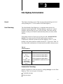
You can send either:
a single message procedure command (Chapter 6) that may be up to 76
characters long.
the name of a Data Highway message procedure which contains a
group of commands and is stored in the 1775–KA module
You specify the station that will receive the command with a PLC–3
extended address. This address always takes the form:
E2.5.nn
where
E2 specifies that this command addresses the module status
area of PLC–3 memory
5 specifies that you are sending the message instruction
through the 1775–KA module
nn is replaced with the thumbwheel setting on your particular
1775–Ka module
32
Chapter 3
Data Highway Communication
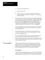
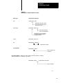
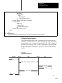
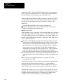
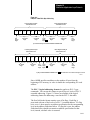
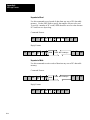
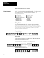
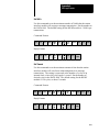
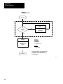
To enter a message instruction, complete the steps below:
1.
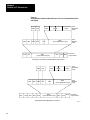
Enter a condition that, when true, will activate the message
instruction. In Figure 3.1, we used an examine–on for input word
00128, bit 01.
Figure 3.1
Levels of Programming in Data Highway Communication
1) PLC–3 Processor
2) 1775–KA Module
Ladder Diagram Program
MSG
10012
01
Data Highway Message Procedure
PROC_A
STAT
EN
12
MESSAGE TYPE 1
CTL = FB200:0000=200
CHANNEL: E2.5.1
STAT
DN
15
@PROC_A
STAT
ER
13
#H024$B12:37 = 15
Message procedure command
to transmit a message to data
highway station number 24
Message instruction to
execute message procedure
PROC_A
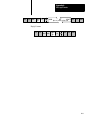
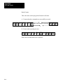
3) Data Highway
DLE
STX
DST SRC CMD STS
TNSW
ADDR
DATA
SIZE (OPTIONAL) DLE
EXT
BCC
Command message
transmitted to
station 24
10014–I
33
Chapter 3
Data Highway Communication
2.
Press the message instruction key.
3.
Specify message type 1.
4.
Choose a control file word where status information about the
message command can be stored. In our Figure 3.1, we used binary
file 200, word 200.
Data transfers can be either solicited or unsolicited, depending on whether
they are initiated by the local or a remote station, respectively. Either type
of station initiates the data transfer by issuing a command message. If the
local station issues the command message, the corresponding reply
message is said to be solicited because the local station has solicited, or
requested, the data contained in the reply message. If a remote station
issues the command message, that message is said to be unsolicited.
For solicited messages, a local station receives data from a remote station
during a read operation. The local station sends data to a remote station
during a write operation.
For unsolicited messages, a local station receives data from a remote
station during a write operation. A local station sends data to a remote
station during a read operation.
In read operations, the command message requests the data transfer, but
the corresponding reply message actually contains the data being
transferred. In write operations, the command message contains the data
being transferred, and the reply message merely reports the status (receipt
or non–receipt) of the transfer.
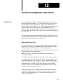
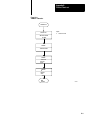
Levels of Programming
The PLC–3 processor must be free to control its own processes at the
same time that the 1775–KA module is communicating over the Data
Highway. For this reason, both the processor and the module have their
own programs and programming languages. Figure 3.1 illustrates how
these two programming levels (processor and module) interrelate.
PLC-3 Program
The first link in the communication process is your PLC–3 ladder diagram
program. You send a Data Highway command message by means of the
message (MSG) instruction. Figure 3.1 shows a typical MSG instruction.
34
Chapter 3
Data Highway Communication
When the rung becomes true, the message instruction begins sending
command(s) across the Data Highway. At the same time, bits in a control
file word change their state (Table 3.B) to reflect the status of the
command. Even if the rung becomes false, the message command will
continue to send commands across the highway.
Table 3.B
The Status of Bits in a Control File Word
WHEN:
the message instruction is true
the enable bit (16) is set
the latched enable bit (12) is set
the remote Data Highway module has received the message instruction
the request bit (17) is set
the 1775-KA module begins operation
the busy bit (14) is set
the operation is complete
the busy bit (14) is set
either the done bit (15) or the error bit (13) is set
the rung becomes false
the request bit (17) is reset
the busy bit (14) is reset
the enable bit (16) is reset
the latched enable bit (12) is reset
the rung becomes true a second time
either the done bit (15) or the error bit (13) is reset
5.
Enter an extended address for the channel. In our Figure 3.1, we
address the module status area of memory, specify the 1775–KA
module, and a thumbwheel setting of 1.
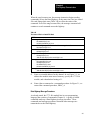
6.
Enter either a command or a command procedure. In Figure 3.1, we
entered the command procedure, PROC_A.
Data Highway Message Procedure
As already stated, the 1775–KA module has its own programming
language that consists of commands (Chapter 8). A group of related
commands make up a Data Highway message procedure. These
commands and message procedures determine what messages are
transmitted over the Data Highway.
35
Chapter 3
Data Highway Communication
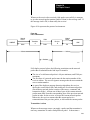
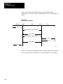
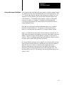
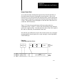
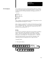
Data Transfers
The whole purpose of Data Highway communication is to transfer data
from one station processor memory location to another. To accomplish
these data transfers, you can program the assignment command into the
1775–KA module.
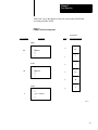
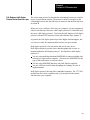
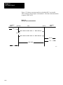
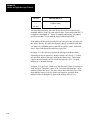
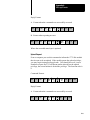
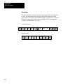
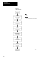
Chapter 6 gives the details of the assignment command. For now, let’s just
look at the simple example in Figure 3.2. In this example, the assignment
command copies a word (16 bits) of data from the source to the
destination location. The source of the data is always specified on the
right of the equals sign (=), and the destination is always on the left.
Figure 3.2
Example Assignment Command
$B45:21 = $I12:33
Source Address
Address Delimiter
Asignment Command
Destination Address
Address Delimiter
10015-I
Note that an assignment command does not destroy the data at the source
location; rather, it just makes a copy of the source data at the destination
location. When the assignment is executed, both source and destination
will contain the same data.
There are two ways to use a data transfer command with the 1775–KA
module:
as a single command within a PLC–3 message instruction
as one of multiple commands within a message procedure
Figure 3.3 illustrates both of these methods for the same assignment
command. Note that a message instruction in the PLC–3 ladder diagram
program controls execution of the command in either case.
36
Chapter 3
Data Highway Communication
Figure 3.3
Two Ways to Use 1775-KA Commands
2) as part of a message procedure
1) as a single command
in a PLC–3 message instruction
Message Procedure PROC_A
MSG
10012
01
MESSAGE TYPE 1
CTL = FB200:0000=200
CHANNEL: E2.5.1
$B45:21=$112:33
STAT
EN
12
(other commands)
STAT
DN
15
$B45:21 = $112:33
STAT
ER
13
(other commands)
PLC–3 Message Instruction to Control
Execution of Procedure PROC_A
MSG
10012
01
MESSAGE TYPE 1
CTL = BW200:0000=200
CHANNEL: E2.5.01
@ PROC_A
STAT
EN
12
STAT
DN
15
STAT
ER
13
10016–I
37
Chapter 3
Data Highway Communication
Access privileges
Not every Data Highway station can read or write to every other station.
In general, read and write access privileges depend on two factors:
type of processor at the transmitting and receiving stations
protections set at the receiving station
The rest of this section explains how these access privileges vary
according to the above factors.
PLC–3 Stations
A PLC–3 station can always read data from any major area of another
PLC–3’s memory. However, one PLC–3 station can write only to the data
table area of another PLC–3 station.
In addition, a local PLC–3 station can prevent remote PLC–3 stations
from writing to the local station’s data table by setting a memory
protection switch. At the local station, the memory protect switch can be
overridden by selecting option 4 in the Module Options Menu (section
titled Accept Writes, chapter 2) at the local station.
PLC/PLC–2 Stations
For communication with a PLC or a PLC–2 station, read, and write access
privileges depend on switch settings at that station. For an explanation of
how to set the switches for read and write access, refer to the
Communication Adapter Module User’s Manual (publications 1771–6.5.1
and 1774–6.5.8).
Accessing a PLC/PLC–2 Station
Access to a PLC/PLC–2 station also depends on the type of command
transmitted to that station. There are two types of commands:
protected write commands
unprotected read and write commands
Protected write commands can only write to specified sections of the data
table in a PLC/PLC–2 processor. Memory access rungs in the PLC/PLC–2
ladder diagram program specify where in the data table the PLC–3 can
write data.
Unprotected commands, on the other hand, can read or write to any
section of the data table at a PLC/PLC–2 station. (Again, refer to
publication 1771–801 or 1774–819 for an explanation of protected and
unprotected commands and memory access rungs.)
38
Chapter 3
Data Highway Communication
A PLC–3 station can read from any part of a PLC/PLC–2 data table.
However, A PLC– 3 station cannot write to a PLC/PLC–2 if the switch
settings at the PLC/PLC–2 station forbid access. If the switches at the
PLC/PLC–2 station are set to accept only protected write commands, then
the ladder diagram program at the PLC/PLC–2 station must contain
memory access rungs to define which areas of the PLC/PLC–2 station’s
data table are accessible. In such a case, a transmitting PLC–3 station can
write to only those data table areas defined by the memory access rungs,
and only by means of protected write commands. If the switches at the
PLC/PLC–2 station are set to accept unprotected write commands, a
PLC–3 station can then write to any area of the PLC/PLC–2’s data table
by transmitting an unprotected write command (section titled Command
Message Type chapter 6).
Accessing a PLC–3 from a PLC/PLC–2 Processor
While a PLC–3 processor can address any area of a PLC/PLC–2 data
table, a PLC/PLC–2 reads an input file that is a part of the PLC–3 data
table. That file is the PLC–3 input file with a number that corresponds to
the station number of the PLC/PLC–2 station. For example, the
read/write files assigned to PLC/PLC–2 stations 1 to 100 (octal) would be
as follows:
[1]
PLC/PLC-2 Station
Number (octal)
Assigned PLC-3 Input File
for Read/Write Access
000
I008[1]
001
I001
002
I002
003
I003
004
I004
005
I005
006
I006
007
I007
010
I010
011
I011
012
I012
.
.
.
.
.
.
077
I077
100
I100
Station address 000 is assigned to input file I008. Otherwise PLC-3 input
files with an 8 or 9 in their address are not used for read/write access by a
PLC-PLC-2 station (except I008 for station 0).
39
Chapter 3
Data Highway Communication
PLC/PLC–2 station numbers are octal, while PLC–3 input files have
decimal addresses. This means that PLC–3 input files with an 8 or 9 in
their address are not used for read/write access by a PLC/PLC–2 station.
The PLC/PLC–2 station can use either protected or unprotected
commands to access its assigned PLC–3 file. Note, however, that the
PLC/PLC–2 station cannot access its assigned file until that file is created
and allocated at the PLC–3. To create a PLC–3 file, use the CREATE
command described in the PLC–3 Programming Manual (publication
1775–801).
Note that it is possible to have two PLC–3 stations communicate with
each other as if they were PLC/PLC–2 stations. To do this, simply allocate
the appropriate PLC/PLC–2 buffer files in the PLC–3 stations and uses
the PLC/PLC–2 addressing format (section titled PLC/PLC–2 Address
Specifications, chapter 4) in the assignment commands. Similarly, a
computer can sent PLC/PLC–2 commands to a PLC–3 station by using
the appropriate message packet formats (Appendix A).
To allow as many as 4 remote stations to access the same PLC–3 input
file:
1.
Enable the PLC–2 MASK option in the LIST function. PLC–2
MASK is option 6 on the Module Options menu.
2.
Select station numbers 1008 apart. For example, you could use
stations 010, 110, 210 and 310.
The stations will have access to the input file which matches the lower
two digits of these station numbers (input file 10 in this example). When
the 1775– KA module receives a PLC–2 type command, it masks the
upper octal digit in order to determine which input file to access. So
commands sent from stations 010, 110, 210, and 310 would all access
input file 10.
310
Chapter 3
Data Highway Communication
PLC–4 Stations
To read or write to a PLC–4 station, you can send either protected or
unprotected commands.
Switches 2 and 3 (on the second row of switches) at the 1773–KA module
specify whether the PLC–4 station will accept unprotected and protected
commands (respectively) through the Data Highway port of the 1773–KA
module.
Switches 1 and 3 (on the third row of switches) at the 1773–Ka module
specify whether the PLC–4 station will accept protected and unprotected
commands (respectively) through the RS–232–C port of the 1773–KA
module. In all cases, if the switch is set to the closed position, the module
will accept that type of command.
311
Chapter
4
Addressing Rules and Examples
General
This chapter presents some general rules for specifying data addresses in
message procedures. This chapter assumes that you are already familiar
with the forms and meanings of addresses in the PLC–3 and other
Allen–Bradley programmable controllers. For details on these subjects,
refer to the appropriate documentation listed in Table 4.A.
Table 4.A
Memory Organization Documentation
Controller
Document
Publication
Number
(Old/New No.)
PLC-3
PLC-3 Programming Manual
1775-801/1775-6.4.1
PLC
PLC Programming & Operations Manuals
1774-800/1774-6.8.1
PLC-2
PLC-2 Memory Organization and Structure
1772-907/---------
PLC-2/30
PLC-2/30 Memory Organization
1772-914/1772-4.4
PLC-2/20
Memory Organization of PLC-2.20 Controller
1772-909/1772-4.3
PLC-2/15
PLC-2/15 Memory Organization
1772-912/---------
PLC-4
PLC-4 Microtrol Product Guide
1773-800/1773-6.5.1
In this chapter,the addressing formats are presented in shorthand notation.
The notation used is as follows:
<bit>
-
the number of a particular bit within the
addressed word
<fileaddr>
-
the logical address of a PLC–3 file
<filesym>
-
a symbolic address of a PLC–3 file
<offset>
-
the number of words between the
beginning of the file and the desired word
(offset is zero for the first word of a file)
<size>
-
number of words of data to be transferred
<wordaddr>
-
the logical address of a PLC–3 word
<wordsym>
-
a symbolic address of a PLC–3 word
41
Chapter 4
Addressing Rules and Examples
An expression can be used in place of any of the above fields in an
address.
Number Systems
Within the above listed fields of an address specification, numbers are
interpreted as decimal (base 10) unless you indicate that they are octal
(base 8). You can specify an octal number by enclosing the number in
parentheses and starting it with a leading zero. For example, 17 is
interpreted as decimal 17, but (017) is interpreted as octal 17, or decimal
15.
An exception to the above rule occurs when addressing a word in the
input or output sections of PLC–3 memory. In these cases, the word
address <wordaddr> is normally interpreted as an octal number,
regardless of leading zeros. To express an input or output word address as
a decimal value, enclose the word address within parentheses and
eliminate leading zeros.
In addressing individual bits, parentheses have no affect on the address
interpretation The bit address <bit> is interpreted as an octal number if it
starts with a leading zero and as a decimal number if it does not start with
a zero.
Figure 4.1 illustrates these addressing conventions.
Figure 4.1
Examples of Addressing Conventions
42
Address
Specification
Interpretation (expressed in decimal)
I12:15
Input file 12, word 13
I12:15/15
Input file 12, word 13, bit 15
I12:015/015
Input file 12, word 13, bit 13
I12:(15)
Input file 12, word 15
I12:(015)
Input file 12, word 13
N43:15
Integer file 43, word 13
N043:15
Integer file 43, word 13
N(043):15
Integer file 35, word 13
N(43):15
Integer file 43, word 13
10017-I
Chapter 4
Addressing Rules and Examples
Data is referenced by its address in memory. In a message procedure, you
must precede an address with a dollar sign. The dollar sign acts as a
delimiter to tell the 1775–KA module that it has encountered a data
address. Figure 4.2 illustrates this addressing format in a simple
assignment command.
Figure 4.2
Example Assignment Command Showing Addressing Format
<
<
$B45:21 = $I12:33
Destination
Address
Source
Address
Assignment Command
10018-I
For data locations at remote stations, the remote station number must
precede the data address. Figure 4.3 illustrates this addressing format.
For communication on the Data Highway, the characters #H are required
to delimit the remote station number. For RS–232–C communication
through the 1775–KA module’s modem port, the characters #M delimit
the remote station number.
Figure 4.3
Example of Remote Station Addressing in an Assignment Command
<
<
#H024 $B45:21 = $I12:33
<
Addresses
Source Address
Address Delimiter
Assignment Command
Destination Address
Address Delimiter
Remote Station Number (octal)
Data Highway Port Identifier
Remote Station Delimiter
10019-I
43
Chapter 4
Addressing Rules and Examples
Symbols
You can also use symbols to represent data and data addresses in message
procedures. A symbol can consist of numeric digits, alphabetic
characters, and the underline character (_). No other special characters
are allowed. The first character in a symbol must be a letter of the
alphabet.
Both upper–case and lower–case letters are acceptable in a symbol, but
they are distinguished. For example, ASYMBOL and Asymbol are two
different symbols.
A symbol can be any length, but it must be unique in its first 8 characters.
For example, SYMBOL_A and SYMBOL_B are distinguishable in a
message procedure, but NEW_SYMBOL_A AND NEW_SYMBOL_B
are not. Note that indistinguishable symbols are not flagged as
programming errors. Rather, indistinguishable symbols are treated as
equivalents.
Certain words and character combinations cannot be used as symbols
because they are reserved for special uses in message procedures. The
reserved words are:
CREATE
IF
DELETE
ON_ERROR
ERROR
PROT
EXIT
STOP
GOTO
UNPRO
Any abbreviated form of one of the above words is also invalid as a
symbol. For example, the single letter C should not be used as a symbol
because it is an abbreviation of the word CREATE. Similarly, PRO is an
invalid symbol.
Figure 4.4 illustrates the classification of different types of symbols. The
two major classifications are:
system symbols
user symbols
44
Chapter 4
Addressing Rules and Examples
Figure 4.4
Symbol Types
User Symbol
Generate this symbolic
value through the
assignment command
Interprocedural
Applies to the procedure
in which it is generated
plus any other procedure
nested together with that
procedure
Symbol
Procedural
Applies only to the
procedure in which it is
generated.
System Symbol
Generate this symbol
with the Edit command
(for a procedure name)
or a Create command
(for a symbolic address).
Procedure Name
Applies to a single
procedure or other
procedures nested
together within that
procedure.
Global
Applies to any context.
Symbolic Address
Can be used anywhere
in place of a logical
address.
Local
Applies only to the
context in which the
symbol is generated.
10021–I
System Symbols
A system symbol is used as either a procedure name or a symbolic
address. The characters in a system symbol must conform to the general
rules given above for all symbols. System symbols are delimited by the
character @, which distinguishes them from user symbols.
Procedure Names
A procedure name is a way of referring to a message procedure. You
assign a procedure name at the time you generate, or edit, the message
procedure (Chapter 6).
One procedure can execute a second procedure simply by stating the
name of that second procedure. This allows for nesting of procedures up
to three levels deep.
Symbolic Addresses
45
Chapter 4
Addressing Rules and Examples
A symbolic address is another way of representing the logical address of
data (section titled Addresses). You can generate a symbolic address by
using the CREATE command (Chapter 8). A symbolic address can be
used anywhere that a logical address can be used in a message procedure.
The symbolic address is stored in the system symbols area of the PLC–3
memory.
Scope of System Symbols
System symbols can be either local or global in scope. A global system
symbol is known in any context. A local system symbol is known only in
the context in operation at the time the symbol was generated. Context is
explained in the PLC–3 Programming Manual (publication 1775–801).
At the time you generate the system symbol, you can specify whether it is
to be local or global. If you do not specify the scope of the system
symbol, it is assumed to be local.
Note that the terms local and global symbols should not be confused with
local and remote stations. Both local and global symbols having meaning
only at the station in which they were generated.
User Symbols
A user symbol represents a numeric value. You can generate a user
symbol and assign a value to it by means of the assignment command
(Chapter 7).
User symbols are either procedural or interprocedural. Procedural user
symbols are known only to the procedure in which they are generated.
Interprocedural user symbols are known to the procedure in which they
are generated and to any other procedure nested within that procedure.
User symbols can contain data that is up to 32 bits long. If the high–order
bits are insignificant (that is, if they can be truncated without changing the
value of the data), then the contents of the user symbol can be stored in a
data field that is less than 32 bits long. Attempting to put a data value into
a field that is too small for it will generate an error code of 189 (Appendix
B).
46
Chapter 4
Addressing Rules and Examples
PLC-3 Address Specifications
The PLC–3 processor uses logical addresses to reference data in memory.
No PLC–3 address is valid unless it memory location has been allocated.
You can allocate memory by using the CREATE command in PLC–3
programming. The PLC–3 Programming Manual (publication 1775–6.4.1)
explains how to do this. Note that the CREATE command for memory
allocation is different than the CREATE command for creating symbolic
addresses (Chapter 6).
The following rules apply when specifying a PLC–3 logical address in a
message procedure:
1. Symbolic addresses must be defined to either the word level or the
file level of specification.
2. A word address may be either: (a) a block address specified to the
word level, (b) a symbolic address of a word, or (c) a symbolic file
address followed by a colon (:) and an offset.
3. A size specification must be preceded by a word address and a
comma (,).
4. An offset specification must be preceded by a file address and a
colon (:).
5. A bit number must be preceded by a word address and a slash (/).
6. To access the pointer or floating point sections of memory, extended
addressing must be used.
These rules are applied in the formats given below for addressing PLC–3
data locations.
Addressing a File
The format for addressing a PLC–3 file is one of the following:
<fileaddr>
<flesym>
For assignment commands that copy data from one file to another, both
the source and the destination file must be exactly the same size.
47
Chapter 4
Addressing Rules and Examples
For PLC–3 timer and counter files, it is important to note that the data
words are stored in the following order:
CTL
PRE
ACC
That is, the control, preset, and accumulated values for a given timer or
counter are stored as consecutive words in the same file.
Addressing a Word Range
To address a range of words in PLC–3 memory, use one of the following
formats:
<wordaddr><size>
<filesym>:<offset>,<size>
<wordsym>,<size>
Figure 4.5 is an example of addressing a range of PLC–3 words.
Figure 4.5
Example of Addressing a Range of PLC-3 Words
<
<
$N 15 : 0, 20
Address of first word
to be transferred.
Number of words to
be transferred
Delimiter
10022-I
You may use a word range only as the source field in an assignment
command. The destination must be a file that is as large as, or larger than,
the source range.
Addressing a Word
To address a single word in PLC–3 memory, use one of the following
formats:
48
Chapter 4
Addressing Rules and Examples
<wordaddr>
<filesym>:<offset>
<wordsym>
Note that <wordaddr>is interpreted as an octal value if the addressed
word is in an input or output file. Otherwise, <wordaddr>is interpreted as
a decimal value (section titled Number Systems).
To access words in the pointer of floating point sections of PLC–3
memory, use the PLC–3 extended addressing format. You can read about
extended addressing in:
PLC–3 Programmable Controller Programming Manual (pub. no.
1775–6.4.1)
Addressing a Bit
To address a specific bit within a PLC–3 word, use one of the following
formats:
<wordaddr>/<bit>
<filesym>:<offset>/<bit>
<wordsym>/<bit>
Figure 4.6 gives some examples of addressing individual bits in PLC–3
memory.
49
Chapter 4
Addressing Rules and Examples
Figure 4.6
Example of Addressing Specific Bits in PLC-3 Memory
<
@FILE_A:16/8
Bit number 8 (decimal)
Delimiter
Word offset from bewginning of file
Delimiter
Symbolic address of file
<
$B1:5/012
Bit number 8 (decimal)
Delimiter
Logical word address
10023-I
PLC/PLC-2 Address
Specifications
The PLC and PLC–2 processors use logical data addresses. These
addresses are usually specified as octal numbers. However, the 1775–KA
module interprets these addresses as decimal numbers unless they contain
leading zeros (section titled Number Systems). Therefore, if you want to
specify a PLC or PLC–2 word address as an octal number, begin the
number with a 0(zero).
Addressing a Word Range
To address a range of words in PLC or PLC–2 memory, use this format:
<offset>,<size>
Figure 4.7 illustrates this addressing format
You may use a word range only as the source field in an assignment
command.
410
Chapter 4
Addressing Rules and Examples
Figure 4.7
Example of Addressing a Range of PLC/PLC-2 Words
<
<
<
#H024$015,4
Number of words to be transferred (decimal)
Delimiter
Word offset from beginning of memory (octal)
Address delimiter
Remote station number
Remote data highway station delimiter
10024–I
Addressing a Word
To address a single word in PLC or PLC–2 memory, use this format:
<offset>
Addressing a Bit
To address an individual bit in PLC or PLC–2 memory, use this format:
<offset>/<bit>
Figure 4.8 illustrates this addressing format.
411
Chapter 4
Addressing Rules and Examples
Figure 4.8
Example of Addressing Specific Bits in PLC/PLC-2 Memory
<
<
<
<
#H015$0121/010
Bit number 10 (octal)
Delimiter
Word offset from beginning of memory (octal)
Address delimiter
Remote station number
Remote data highway station delimiter
10025–I
Remote Station Address
Specifications
To specify the address of data at a remote station, use the format shown in
Figure 4.9. This format applies to both PLC–3 and non–PLC–3 remote
stations. The characters #H delimit a remote Date Highway station, and
the characters #M delimit a remote modem station.
Figure 4.9
Example of Addressing a Word in a Remote PLC-3 Station
<
<
#H 020 $ B 15:9
Word address at remote station
Address delimiter
Remote station number 20 (octal)
Port identification for data highway port
Remote station delimiter
<
<
#H 020 @ WORD_9
Symbolic word address defined at remote station
Remote station number 20 (octal)
Port identifier for data highway port
Remote station delimiter
Remote station addresses are subject to the following restrictions:
412
10026-I
Chapter 4
Addressing Rules and Examples
1. A remote address can be used only with the single equals sign (=)
type of assignment command.
2. In the assignment command, either the source or the destination, but
not both, may be a remote address.
3. A remote address may contain an embedded expression, but a remote
address may not be embedded in an expression.
Expression
Expressions use operators to combine two or more numeric values into a
single value. Table 4.B lists the operators that can be used in an
expression. These operators are listed from highest priority (1) to lowest
priority (10). Expressions may be nested within other expressions by
enclosing the inner expression within parentheses.
Table 4.B
Expression Operators
Operator
/
Operation
Order of
Execution
Bit operator
1
Logical complement
1
Bitwise 32-bit complement
1
*
Multiplication of 32 bits
2
%
Division of 32 bits
2
+
Addition of 32 bits
3
-
Subtraction of 32 bits
3
<<
Left arithmetic shift
4
>>
Right arithmetic shift
4
& or .BAND.
Bitwise 32-bit AND
5
or .BXOR.
Bitwise 32-bit EXCLUSIVE OR
6
or .BOR.
Bitwise 32-bit OR
7
.EQ.
Compare equals
8
.GT.
Compare greater than
8
.GE.
Compare greater or equal
8
.NOT.
or .BNOT.
413
Chapter 4
Addressing Rules and Examples
Operator
Operation
Order of
Execution
.LT.
Compare less than
8
.LE.
Compare less or equal
8
.NE.
Compare not equal
8
.AND.
Logical AND
9
.OR.
Logical OR
10
The result of an expression depends on the order in which the operators
are executed. The order of execution depends on the type of operator and
on left– to–right placement within the expression. Table 4.B gives the
order of execution for the different operators. For example, the command
$B67:45 = 6+3*2
would store the value 12 in word 45 of binary file 67. This is because
multiplication is performed before addition.
If an expression contains several operators with the same order of
execution, those operators will be executed in the left–to–right order in
which they appear within the expression. Extra set of parentheses can be
nested within each other to change the order of execution. In such cases,
the expression within the inner–most set of parentheses is evaluated first.
For example, the command
$B67:45=36%((6+3)*2)
would store the value 2 in word 45 of binary file 67 (% is the operator for
division).
Expressions can be used anywhere that direct numeric values can be used
within a message procedure, including within an address field. For
example, in the statement
$B67:(WORD+3)=5
the expression (WORD+3) specifies the address of a word within binary
file 67. Note that the parentheses are necessary to indicate that +3 is part
of the word address in this case.
414
Chapter 4
Addressing Rules and Examples
Number Systems
Within an expression, direct values are always interpreted as decimal
(base 10) numbers unless you indicate that they are octal (base 8). You
can specify an octal value by starting the number with a leading zero. For
example, 17 in an expression is interpreted as decimal 17, but 017 is
interpreted as octal 17 (or decimal 15).
Operators
This section describes the operators listed in Table 4.B.
Bit Operator
The bit operator allows you to address a specific bit of a value stored
under a user symbol. For example, the statement
$I12:24/7=US_3/4
puts the value (0 or 1) of bit number 4 of user symbol US_3 into input file
12, word 24, bit 7.
The bit address itself can also be a user symbol or an expression. For
example, in the statement
$I12:24/7=US_3/(4+US_1)
the expression (4+US_1) specifies a particular bit within user symbol
US_3.
Note that the value appearing after the bit operator must be within the
range of values allowed for bit addresses. Since user symbols are 32–bit
values, a bit address for a user symbol must be in the range of 0 to 31
(decimal). Bit addresses for data table words must fall in the range of 0 to
15 (decimal).
Logical Operators
The logical operations are complement, AND, and OR. These operations
are used to construct logically true or false conditions. They are generally
used in decision statements such as the IF command (see section titled IF
Command, chapter 6).
415
Chapter 4
Addressing Rules and Examples
The result of a logical complement is 1 (true) if the expression following
the .NOT. is a value of 0 (zero). Otherwise, the result is 0 (false). For
example, consider the command
$I12:24=.NOT.SYMBOL_A
If the value of SYMBOL_A is 0 (zero), then a 1 is stored in word 24 of
input file 12. If the value of SYMBOL_A IS anything other than 0, then a
0 (zero) is stored in word 24 of input file 12.
The result of a logical AND is 1 (true) if the expression preceding the
.AND. and the expression following the .AND. are both non–zero.
Otherwise, the result is 0 (false).
The result of a logical OR is 1 (true) if either the expression preceding the
.OR., the expression following the .OR., or both expressions are
non–zero. Otherwise, the result is 0 (false).
Bitwise 32–Bit Operators
Bitwise 32–bit operators manipulate the individual bits in a 32–bit
operand.
The bitwise 32–bit complement (.BNOT.) inverts the state of each bit in
the 32– bit expression. That is, bits set to 1 are inverted to 0, and bits set
to 0 are inverted to 1.
The bitwise 32–bit AND (.BAND.) forms a bit–by–bit logical AND of
two 32–bit operands. There is no carry from one bit position to the next
within the operand. For example, if
A contains the bit pattern
10101010010011110010101010101011
B contains the bit pattern
01110101011100100010101110001010
then the assignment C=A.BAND.B yields
C contains the bit pattern
00100000010000100010101010001010
416
Chapter 4
Addressing Rules and Examples
The bitwise 32–bit EXCLUSIVE OR (.BXOR.) forms a bit–by–bit logical
EXCLUSIVE OR of two 32–bit operands. There is not carry from one bit
position to the next within the operand.
The bitwise 32–bit OR (.BOR.) forms the bit–by–bit logical OR of two
32–bit operands. There is not carry from one bit position to the next
within the operand.
Arithmetic Operators
The arithmetic operations are addition, subtracting, multiplication, and
division. These are binary (not BCD) operations that produce 32–bit
signed integer results.
A result from these arithmetic operations should normally be assigned to a
32– bit destination. The result can be assigned to a 16–bit destination only
if the result is small enough in absolute value (less than 65,535) to fit into
16 bits. If the result is assigned to a 16–bit destination but is too large to
fit into 16 bits, then an error code of 215 results.
There is no indication of overflow or underflow conditions with
arithmetic operations.
Shift Operators
When a left arithmetic shift (<<) is executed, zeros are shifted into the
rightmost bits of the expression. The leftmost bit are shifted out of the
expression and are lost.
When a right arithmetic shift (>>) is executed, the leftmost bit of the
expression does not change. If the leftmost bits is a 1, then 1’s are shifted
in from the left. If the leftmost bit is a 0 (zero), then 0’s are shifted in
from the left. Since the leftmost bit of an expression is the sign bit, this
means that the right arithmetic shift does not change the sign of a numeric
value. The rightmost bits are shifted out of the expression and are lost.
Comparison Operators
Comparison operators result in a value of 1 if the comparison is true and 0
(zero) if the comparison is false. For example, consider the command
$I12:23 = ($CACC:1.GE.$CACC:2)
417
Chapter 4
Addressing Rules and Examples
If the accumulated value of counter 1 is greater than or equal to the
accumulated value of counter 2, then the number 1 is stored in word 23 of
input file 12. If the accumulated value of counter is less than the
accumulated value of counter 2, a value of 0 (zero) is stored in word 23 of
input file 12.
Resulting Values
The result of an expression is a 32–bit value. If the high–order bits are
not significant (that is, if they can be truncated without changing the value
of the expression), then the result can be stored in a data field that is less
than 32 bits long. Attempting to put a value into a field that is too small
for it results in an error code of 215 (Appendix B).
418
Chapter
5
Editing
General
This chapter explains how to create and edit message procedures and
commands for the 1775–KA module. The message procedure commands
themselves are described in Chapter 6.
The general steps for editing a 1775–KA message procedure are:
1.
Create and edit the PLC–3 ladder diagram program containing
message instructions to control execution of the 1775–KA message
procedure.
2.
Allocate memory to the necessary PLC–3 data files.
3.
Create and edit the 1775–KA message procedure.
You can perform the first two steps through an Industrial Terminal (cat.
no. 1770–T4) connected to the I/O Scanner–Programmer Interface
Module (cat. no. 1775–S4A). The third step can be performed either
through an Industrial Terminal or through a data terminal connected to the
I/O Scanner–Message Handling Module (cat. no. 1775–S4B). These steps
are described below.
Editing the Message Instruction
Table 5.A gives an example of how to edit the message instruction in the
PLC–3 ladder diagram program. For more details on this type of editing,
refer to the PLC–3 Programming Manual (publication 1775–801).
51
Chapter 5
Editing
Table 5.A
Example of Message instruction Editing
System Prompt
Action
Key Strokes
Start edits.
SED [ENT]
Insert rung.
IR [ENT]
Enter the energize bit for the message
rung. In this case, binary file 0, word 0, bit
0.
-] [- B0:0/0 [ENT]
Enter the message instruction.
MSG [ENT]
ENTER FILE ADDRESS
Enter the address of the file where the
message instruction will reside in memory.
In this case, binary file 1.
FB1 [ENT]
ENTER SYSTEM
ADDRESS OR
SYMBOL
Enter the channel designation for the
1775-KA module. In this case, 2 is the
module status, 5 is the 1775-KA module
type, and 1 is the thumbwheel number of
the module.
E2.5.1 [ENT]
ENTER MESSAGE
TYPE
Enter the message type. This is always 1
for the 1775-KA module.
1 [ENT]
Enter a single 1775-KA assignment
command or the name of a message
procedure. In this case, the name of the
message procedure is PROC_1.
@PROC-1 [ENT]
End edits.
EE [ENT]
Allocating Memory
Before the 1775–KA module can transfer data to or from any file in
PLC–3 memory, that file must exist and it must have enough memory
allocated to it to accommodate the data transfer. You can create and
allocate a file using the PLC–3 memory management commands. Refer to
the PLC–3 Programming Manual (publication 1775–801) for a description
of memory management.
Editing Message Procedures
Table 5.B shows an example of editing a message procedure through an
Industrial Terminal connected to a 1775–S4A module. Table 5.C shows
how to edit the same message procedure through a data terminal
connected to a 1775–S4B module.
52
Chapter 5
Table 5.B
Example of Editing a Message Procedure Through an Industrial Terminal
System Prompt
Action
Key Strokes
Create the message procedure. In this
case, MH1 mean Data Highway message
procedure number 1.
ME, MH1, [ENT]
Deleting existing null characters.
[DEL] [DEL] [DEL] [DEL]
Enter message procedure commands.
Note that you must use either an EXIT or a
STOP command to end each procedure.
(other commands)
#H022$B0:5CC:1 [ENT]
$B0:6=CC:1*2 [ENT]
EXIT [ENT]
[CANCEL CMD]
Insert the symbol definition for the name of
the message procedure.
IS [ENT]
ENTER SYMBOL
STRING
Enter the name of the message procedure.
In this case, the name is PROC_1.
PROC_1 [ENT]
ENTER SYSTEM
ADDRESS OR
SYMBOL
Enter the address where the message
procedure is stored. In this case, the
symbolic address MH1 can be used.
MH1 [ENT]
ENTER SYMBOL TYPE
Enter the symbol type for the message
procedure name. This is always 2 for the
1775-KA module.
2 [ENT]
Table 5.C
Example of Editing a Message Procedure Through a Data Terminal
S4B>
Enter the edit mode and create the
message procedure name. Note that the
1775-S4B module automatically creates
the symbol definition for the message
procedure name.
EDIT /H@PROC_1 [RET]
<EOB>*
*
Enter the insert mode of editing
I [RET]
Enter the message procedure command.
Note that you must use either EXIT or
STOP command to end each procedure.
(other commands)
#H022$B0:5=CC:1 [RET]
$B0:6=CC:1*2 [RET]
EXIT [RET]
Exit from the insert mode of editing.
[RET]
Exit from the editing mode of the
1775-S4B module.
E [RET]
S4B>
53
Chapter 5
Editing
Note that it is not always necessary to create a message procedure. If you
want to execute just a single assignment command that is no more than 76
characters long, then you can enter that command as part of the ladder
diagram message instruction (Table 5.A). If you want to execute more
than one 1775–KA command, or if a single assignment command is more
than 76 characters long, then you must create a message procedure to
contain those commands.
Also note that every message procedure must end with either an EXIT or
a STOP command. The EXIT command is normally preferred because the
STOP command is a more extreme measure that results in error 179
(Appendix B).
54
Chapter
6
Message Procedure Commands
General
The 1775–KA module has its own command language that you can use in
programming message procedures. This chapter describes the available
commands and gives some examples on how to use them. Table 6.A
summarizes the commands.
Table 6.A
Message Procedure Commands
Command
Format and Explanation
=
(assignment)
<destination>3=<source>
CREATE
C@<system symbol><logical address>
Create a symbolic address and equate it to a logical address.
DELETE
D @<system symbol>
Delete a symbolic address or an entire message procedure
from PLC-3 memory.
(execute)
@<system symbol>
Execute the named message procedure.
EXIT
E
Terminate execution of the current message procedure.
GOTO
G <label>
Continue executing the current procedure from the point
specified by the label.
IF
I <expression><embedded command>
Execute the embedded command only if the specified
expression is true.
ON_ERROR
O <embedded command>3
Execute the embedded command only if an error occurs after
this statement in the procedure.
STOP
S
Terminate execution of the message (MSG) instruction in the
PLC-3 ladder diagram program.
Assign a numeric value to a user symbol or copy data from
the source to the destination
Each command can be abbreviated to the letters shown in the format
column of Table 6.A. In general, it is best to abbreviate a command to the
shortest possible form. This not only makes the commands easier to
program, but it also saves memory space and reduces execution time.
61
Chapter 6
Message Procedure Commands
Blanks may be inserted anywhere to improve the readability of a message
procedure. However, blanks should be kept to a minimum because they
use memory space and slow execution of the message procedure.
Assignment Command
The assignment command is the most fundamental yet versatile of all the
commands. Its primary purpose is to copy data from the source location to
the destination location. Table 6.B lists the various types of sources and
destinations. Any type of source in Table 6.B may be used with any type
of destination listed.
Table 6.B
Data Source and Destination Types
Source
Destination
Direct Value
Procedural user symbol
Procedural user symbol (except when
source is remote)
Interprocedural user symbol
Interprocedural user symbol (except
when source is remote)
Logical address
Logical address
Local symbolic address
Local symbolic address
Global symbolic address
Global symbolic address
Expression
Of special interest is the case where a user symbol is the destination of the
assignment. In such a case, if the user symbol was not previously defined
in the message procedure, a new symbol is generated. If the symbol has
already been defined, using it again as a destination causes its value to be
changed to the value given it by the latest assignment command.
Note that you can not transfer data from another station and place it into a
user symbol defined at your local PLC–3.
Format
The equals sign (=) is the assignment command. As Table 6.A shows, the
destination for the assignment is on the left of the equal sign, and the
source or the numeric value is on the right. In all cases, the source value is
assigned to (or copied to) the destination location. Thus, the assignment
is from right to left on the command line. For example, the statement
$I12:024–US_5
62
Chapter 6
Message Procedure Commands
copies the value of user symbol US_5 into word 24 (octal) of input file
12.
Modifiers
Several modifiers may be added to the basic assignment command. These
modifiers affect three aspects of the assignment:
Scope of assignment
Priority level of Data Highway message
Type of command message transmitted
Scope of Assignment
A double equals sign (==) can also be used for the assignment command.
The extra equals sign modifies the scope of an assignment involving a
user symbol. If the destination of the assignment is a user symbol, the
double equals sign defines the destination to be an interprocedural user
symbol. With the single equals sign, the destination becomes a procedural
user symbol.
For example, the statement
US_2==6
defines US_2 to be an interprocedural user symbol and assigns to it the
value 6.
Do not use the double equals sign (==) with anything other than a user
symbol as the destination.
Message Priority
Data Highway messages may be either one of the following priority
levels:
63
Chapter 6
Message Procedure Commands
Normal
Priority
If you use the less–than sign (<) with the assignment command, the
command will generate a priority Data Highway message. Without the
less–than sign, the assignment command will generate a normal Data
Highway message.
For example, the statement
#H027$I15:4<=$I12:24
transmits a priority message to Data Highway station 27 (octal).
The priority modifier can be used with either type of assignment (=or==).
Important: Stations with high priority messages are given priority over
stations with normal priority messages throughout the command/reply
cycle. For this reason, a command should be given a high priority
designation only when special handling of specific data is required. Using
an excessive number of high priority commands defeats the purpose of
this feature and could delay or inhibit the transmission of normal priority
messages.
Command Message Type
Command messages are of two types:
protected
unprotected
As explained in section titled Data Transfers, (chapter 3), protected
commands can access only specified areas of data table memory at a
PLC/PLC–2 station. You will need to send a protected write command
only if a switch at the remote PLC/PLC–2 prohibits other stations from
sending unprotected write commands. Unprotected commands can access
any area of the data table.
By default, command messages generated by the assignment command in
PLC–3 message procedures are of the protected type. To generate an
unprotected command message, use a blank space and the modifier U
after the assignment command.
64
Chapter 6
Message Procedure Commands
For example, the command
#H027$0121=17407
would generate a protected write command to write the value 1740–7 into
word 121 of Data Highway station 27. The command
#H027$0121=17407 U
would generate an unprotected command to do the same thing.
You may disable the transmission of unprotected commands through LIST
options (section titled Module Options, chapter 2).
CREATE Command
The CREATE command generates a symbolic address and assigns it to a
logical address. Table 6.A illustrates the format of the CREATE
command. To create a local symbolic address, use the CREATE command
by itself (the modifier/LOCAL is optional). To create a global symbolic
address, use the modifier/GLOBAL after the CREATE command. In
either case, the symbol has meaning only at the station where it was
created.
The modifier/GLOBAL can be abbreviated to /G, and /LOCAL can be
abbreviated to /L. For example, the statement
C/G @ TOTAL $E0.0.0.7
creates the global system symbol TOTAL to represent the logical address
E0.0.0.7.
Note that this CREATE command for generating symbolic addresses
should not be confused with the CREATE command for allocating file
space in PLC–3 programming (Chapter 4).
DELETE Command
The DELETE command serves three main purposes:
Deleting message procedures from PLC–3 memory
Deleting symbolic addresses
Deleting interprocedural user symbols
65
Chapter 6
Message Procedure Commands
Using the DELETE command on a procedure name not only deletes the
name but also erases the named procedure from PLC–3 memory. Using
DELETE on a symbolic address or interprocedural user symbol merely
deletes the symbol, but the data stored under that symbol remains intact.
Table 6.A shows the general format of the DELETE command. To delete
a symbol or a procedure from the current context, use the DELETE
command by itself (the modifier /LOCAL is optional). To delete a
symbol or a procedure from all contexts, use the modifier/GLOBAL after
the DELETE command.
The modifier /GLOBAL can be abbreviated to /G, and /LOCAL can be
abbreviated to /L. For example, the statement
D/G @ PARTS_PGM
deletes the procedure PARTS_PGM from all contexts in PLC–3 memory.
Note that the /LOCAL modifier can be used on global system symbols. In
such cases, the procedure or the symbol is deleted from the current
context but can still be used in the other contexts.
Execute
To execute a message procedure, simply enter the delimiter @ followed
by the procedure’s name. For example, the statement
@FIRST_PROC
causes execution of the procedure named FIRST_PROC.
Procedure names may be used anywhere that command can be used. In
this way, one procedure can execute (call) another procedure. This allows
for nesting of procedures. However, procedures may not be nested more
than 3 layers deep.
EXIT Command
66
The EXIT command terminates execution of the current message
procedure. If the current procedure was called (executed) by another
procedure, the EXIT command returns control to the calling procedure.
Control returns to the line following the execute statement.
Chapter 6
Message Procedure Commands
The format of the EXIT command is simply the single letter
E
Without any modifiers or parameters.
Each main procedure and nested procedure must end with either an EXIT
command or a STOP command. The EXIT command is the preferred
means of ending a procedure because the STOP command results in error
179 (Appendix B).
GOTO Command
The commands in a message procedure are normally executed
sequentially. The GOTO command can change the order of execution.
Table 6.A illustrates the format of the GOTO command. Note that the
parameter for a GOTO command is a label. Labels are signposts, or tags,
that mark a location within the message procedure.
To generate a label, simply enter it on any one of the lines in a message
procedure. The format for the label is
LABEL _A:
Nothing else may appear on the same line with the label. The label itself
must conform to the same rules of construction as user symbols do. The
trailing colon (:) is required when you first generate the label, but do not
use the colon any other time you refer to the label.
When a GOTO command is encountered, execution of the message
procedure resumes with the first command after the label specified in the
GOTO. Note that you cannot use the GOTO command to jump from one
procedure to another, even if the procedures are nested.
IF Command
The IF command makes logic decisions in the message procedure. Table
6.A shows the format of the IF command. The first parameter of the IF
command is an expression (Chapter 4). The entire expression must be
enclosed in a set of parentheses. The expression may be made as complex
as desired through the use of multiple operators and nested expression.
The second element in the IF command is an embedded command. If the
value of the expression is true (1), the embedded command is executed. If
67
Chapter 6
Message Procedure Commands
the value of the expression is false (0), the embedded command is not
executed. The embedded command may be any of the available
commands except another IF or an ON_ERROR.
Figure 6.1 demonstrates the combination of a label, a GOTO command,
and an IF command to construct a simple loop that assigns the integers 0
through 7 to successive words in binary file 50.
Figure 6.1
Example of Looping
NUM = 0
LOOP: $B50:(NUM) = NUM
NUM = (NUM +1)
IF (NUM .LE. 7) GOTO LOOP
10027-I
ON_ERROR Command
The ON_ERROR command specifies what action should be taken if an
error is encountered during execution of the message procedure. The
ON_ERROR command is not executed sequentially in the procedure; it is
executed only when an error occurs.
Table 6.A illustrates the format of the ON_ERROR command. The
ON_ERROR command contains an embedded command that is executed
when an error occurs.
The ON_ERROR command applies to all other commands between itself
and the next ON_ERROR command. For example, consider the following
sequence:
68
Chapter 6
Message Procedure Commands
command line 1
command line 2
ON_ERROR GOTO RECOVER
command line 3
command line 4
ON_ERROR ERR_CODE = $B2:16
command line 5
In this sequence, the first ON_ERROR command applies to command
lines 3 and 4, while the second ON_ERROR command applies to
command line 5.
Some command lines might not have an ON_ERROR command that
applies to them. If an error occurs in such a command line,the procedure
will stop executing.
Appendix B lists the error conditions.
STOP Command
The STOP command terminates execution of the MSG instruction in the
PLC–3 ladder diagram program. This means that the STOP command
stops execution of the current procedure and all procedures nested
together with the current one.
The format of the STOP command is simply the single letter
S
without any modifiers or parameters.
The STOP command is a drastic means of terminating a message
procedure, so it should be used only when no other action is possible. The
normal means of terminating a procedure is the EXIT command (section
titled EXIT Command). When the STOP command is used, it results in an
error code of 179 (Appendix B).
Functions
In addition to containing commands and nested procedures, a message
procedure can also contain functions. Functions can be used anywhere
expressions can be used.
69
Chapter 6
Message Procedure Commands
There are two functions:
TO_BCD
FROM_BCD
Figure 6.2 illustrates the format of these functions as they might appear in
an assignment command.
Figure 6.2
Examples of TO-BCD and FROM-BCD Functions
<
<
<
$D:12 = TO_BCD (27)
COUNT = FROM_BCD ($D:12)
Function Parameter
Function
Assignment Command
Destination of
Resulting Value
10028–I
The parameter of the function must be enclosed in parentheses. The
parameter may be any one of the following:
A direct numeric value (either decimal or octal)
An expression
A user symbol
A logical address
A symbolic address
TO_BCD Function
The TO_BCD function converts its parameter into a binary coded decimal
value that is 32 bits long. For example, the TO_BCD function in
Figure 6.2 stores the number 27 in binary–coded–decimal format in word
12 of the decimal section of PLC–3 memory. After this function is
executed, word 12 will contain the following bit pattern:
0000 0000 0010 0111
610
Chapter 6
Message Procedure Commands
FROM_BCD Function
The FROM_BCD function converts its parameter from
binary–coded–decimal format to binary format. The resulting value is 32
bits long. For example, the FROM_BCD function in Figure 6.2 converts
the contents of decimal word 12 from binary coded decimal to a regular
decimal value of 27. From the above example (section titled TO_BCD
Function), the FROM_BCD function stores the following bit pattern in
user symbol COUNT:
0000 0000 0000 0000 0000
0000
0001 1011
As you can see from these examples, TO_BCD and FROM_BCD perform
opposite functions.
You can add your own explanatory comments to any command line in a
message procedure. To do this, enter a semicolon (;) after the command.
Then enter your comment after the semicolon. Figure 6.3 illustrates the
format for comments.
Figure 6.3
Format for Comments
; INITIALIZE COUNTER
<
COUNT = 0
<
Comments
Comment
Comment Delimiter
Command
10029–I
Anything that appears between a semicolon and the end of the command
line is considered to be a comment. Comments may be any length. The
end of the command line, and therefore the end of your comment, is
delimited by the carriage– return and line–feed pair of characters.
A comment can be the only thing on a line. Do not use comments on the
same line as label. Doing so will cause errors in the message procedure.
611
Chapter
7
Error Reporting
General
The 1775–KA module detects and reports various types of errors.
Appendix B lists all the errors reported by the module. As you can see
from the appendix, some of the error codes relate to communications over
the Data Highway, while others relate to programming errors in the
message procedures.
Reporting Error Codes
The 1775–KA module reports errors by their code numbers. The module
stores the error code in the interprocedural user symbol ERROR. The
symbol ERROR should be reserved exclusively for error reporting by the
module, so do not use this symbol for any other purpose.
ERROR contains only the last error encountered during execution of a
command or message procedure. If you want to save the error code or
manipulate it in any way, use an assignment command to copy the code
into a more permanent storage word.
Recovery from Errors
Unless you specify differently, the 1775–KA module will stop executing
the current message procedure as soon as the module detects an error. To
specify a different action, use the ON_ERROR command in the message
procedure. Then, when the module encounters an error, it will perform the
action specified in the nearest preceding ON_ERROR command. After
the module is done performing the ON_ERROR action, it will resume
executing the message procedure at the next command line after the one
in which the error occurred.
For example, a message procedure can contain the command
ON_ERROR @ RECOVER
When an error occurs in the procedure, the above command will cause the
1775–KA module to execute the procedure named RECOVER. The
procedure RECOVER might be a routine for monitoring error codes.
After executing RECOVER, the module will resume executing the
original procedure at the next command line following the one in which
the error occurred.
71
Chapter 7
Error Reporting
Error Monitoring
To aid in error monitoring, the 1775–KA module maintains a 6–word
error block in the module status area of PLC–3 memory. This error block
contains the following information:
Word 0 – error code for the last error that occurred in the current
message procedure
Word 1 – total number of errors that occurred in the current message
procedure
Word 2 – always contains the value 1
Word 3 – line number where the error occurred in the highest level
(nest level 1) message procedure
Word 4 – line number where the error occurred in the next highest level
(nest level 2) message procedure
Word 5 – line number where the error occurred in the lowest level (nest
level 3) message procedure
The error codes reported are those listed in Appendix B.
The line number is the relative location of a command line from the
beginning of the message procedure containing the line. The first line of
each procedure is line number 1, and any following lines are numbered in
ascending sequence. Nested procedures begin with line 1 again, thus the
need for words 3, 4, and 5 in the error block.
You do not enter the line numbers for a procedure; the 1775–KA module
automatically keeps track of the line numbers for you. The line numbers
do not appear in a listing of the message procedure, but they are recorded
internally by the module.
Error Block Operation
Figure 7.1 illustrates how the error block works. In this figure, an
addressing error (invalid destination address) occurs in procedure SUB2,
which is nested 3 levels deep. Word 5 of the error block gives the line
number where the error occurred in procedure SUB2. Word 4 gives the
number of the line in procedure SUB1 that executed procedure SUB2.
72
Chapter 7
Error Reporting
And word 3 gives the number of the line in procedure MAIN that
executed procedure SUB1.
Figure 7.1
Examples of Error Block Operation
Error Block
Line Number
Procedure
Word
Contents (decimal)
MAIN
•
•
•
150
0
124
@SUB 1
•
•
•
SUB 1
1
1
2
1
•
•
•
28
@SUB 2
•
•
•
3
4
28
5
5
SUB 2
•
•
•
5
150
6:12 = COUNT
•
•
•
10030–I
73
Chapter 7
Error Reporting
Note that an ON_ERROR or an IF command may contain an embedded
command to execute another procedure. In these cases, the embedded
execute command is treated just like a nesting level. Figure 7.2 illustrates
this point for an ON_ERROR command. In this figure, an addressing
error in line 10 of procedure MAIN causes activation of the ON_ERROR
command, which calls for execution of procedure SAM. But SAM also
contains an error. The error in SAM is the last one detected, so it is the
one finally reported in the error block. Since procedure SAM is called by
the ON_ERROR command in procedure MAIN, the nesting for SAM is 2
levels deep.
Figure 7.2
Examples of ON_ERROR Nesting
Error Block
Line Number
Procedure
Word
Contents (decimal)
MAIN
ON_ERROR @SAM
1
•
•
160
1
2
2
1
3
1
4
8
5
0
7.2 = 1000
•
•
•
10
SAM
8
0
•
•
•
•
•
$25:0 = N
•
•
10031–I
74
Chapter 7
Error Reporting
Access to Error Block
The error block retains its data even after the message procedures are
done executing. It is re–initialized with each execution of a MSG
instruction in the PLC–3 ladder diagram program.
The extended address for the beginning of the error block file is
$E2.5.nn.4.0.
where “nn” is the thumbwheel number of the 1775–KA module. You can
access this error block by any one of the following means:
Displaying it through the front panel of the PLC–3 controller
Using the data monitor mode of the Industrial Terminal (cat. no.
1770–T4)
Using the move status (MVS) command in the PLC–3 ladder diagram
program
Using the I/O Scanner–Message Handling Module (cat. no. 1775–S4B)
Using the 1775–KA module
Using the 1775–GA
75
Chapter
8
Programming Examples
General
This chapter presents some detailed examples of 1775–KA module
commands and message procedures.
Individual Commands
The first set of examples shows individual commands that could be
programmed directly into a PLC–3 message (MSG) instruction. Figure
8.1 illustrates the differences in reading and writing data between two
PLC–3 stations. Figure 8.2 shows how to write different types of data to a
remote PLC–3 station. Figure 8.3 shows how to write different types of
data to a remote PLC or PLC–2 station.
Figure 8.1
Reading and Writing PLC-3 Data Word
Reading word 5 of binary file 3 at data highway station 045 into word 17 of integer file 4.
I0012
01
MSG
MESSAGE TYPE 1
CTL = FB200:0000=200
CHANNEL: E2.5.1
$NA:17=#H045 $B3:5
Destination
(local)
STAT
EN
12
STAT
DN
15
STAT
ER
13
Source
(remote)
Writing word 5 of binary file 3 into word 17 of integer file 4 at data highway station 045.
I0012
02
MSG
MESSAGE TYPE 1
CTL = FB200:0001=200
CHANNEL: E2.5.1
#H045=N4:17 $B3:5
Destination
(remote)
Source
(local)
STAT
EN
12
STAT
DN
15
STAT
ER
13
10032-I
81
Chapter 8
Programming Examples
Figure 8.2
Writing Data to a Remote PLC-3 Station
Data Type
Assignment Statement
File
#H045$N4 = $B3
Destination file must be
exactly the same size as
source file.
Word range
#H045$N4:17 = $B3:5,20
20 words starting at
word 5 of binary file 3
Destination file must be large
enough to accept full range
being transferred.
Word
#H045$N4:17 = $B3:5
Bit
#H045$N4:17/5 = $B3:5/13
Decimal bit numbers
10033-I
82
Chapter 8
Programming Examples
Figure 8.3
Writing Data to a Remote PLC/PLC-2 Station
Data Type
Assignment Statement
File
#H021$040 = $B3
Destination PLC/PLC–2 file
must be at least as large as
source PLC–3 file.
Word range
#H021$040 = $B3:5,20
20 words starting at
word 5 of binary file 3
Destination file must be large
enough to accept all words
being transferred.
Word
#H021$040 = $B3:5/13
Bit
#H021$040/5 = $B3:5/13
Decimal bit numbers
Priority Write
#H021$040 <= $B3:5
Priority assignment
command
Unprotected Write ––affected by switch settings at remote PLC/PLC–2 station
(refer to publication 1771–802 or 1774–6.5.8.)
#H021$040 = $B3:5
U Unprotected command
Space required
10034-I
83
Chapter 8
Programming Examples
Message Procedure
Figure 8.4 presents a printed listing of a Data Highway message
procedure. As the listing indicates, the purpose of the procedure is to
monitor the state of a status bit in a remote Data Highway station.
Figure 8.4
Example Data Highway Message Procedure
;
PROCEDURE –– @REM_TURNON
; This procedure will monitor the state of a bit in a remote
; station and, when that bit goes true, turn on a bit
; locally for either 300 seconds or until the remote bit
; goes false.
;
ON_ERROR @LOG_ERROR
;log errors and time of day
A = = 0
;initialize error pointer
CREATE @TIM–START $B0:0
;timer start word
CREATE @TIM_CTL $TCTL:1
;timer control word
CREATE @TIM_PRE $TPRE:1
;timer preset word
T_ON_BIT = 0
;timer on bit
T_DONE_BIT = 017
;timer done bit
CREATE @PROCESS $N3:7
;process word
P_ON_BIT = 5
;process on bit
ON = 1
OFF = 0
;check remote bit in loop
LOOP 1:
;fetch and save remote bit
B0:0/1 = $H023$B5:3/2
IF ($B0:0/1 .EQ. OF) GOTO LOOP1
;set timer for 300 sec
@TIM_PRE = 300
;turn timer on
@TIM_START/T_ON_BIT = ON
;turn process on
@PROCESS/P_ON_BIT = ON
;check timer and remote bit in loop
LOOP 2:
;fetch and save remote bit
$B0:0/1 = $H023$B:3/2
IF (($B0:0/1 .EQ. ON) .AND. (@TIM_CTL/T_DONE_BIT .EQ. OFF)) GOTO LOOP2
@PROCESS/P_ON_BIT = OFF
EXIT
;
PROCEDURE –– @LOG_ERROR
;This procedure will fetch the error block out of the
; Module Status Area and record it along with the time
; of day in status file 5.
;
CREATE @STATUS $S5
CREATE @ERR_BLK $E2.5.1.4.0
CREATE @TOD $S1:3
;copy error block (6 words)
@STATUS: (A) = @ERR_BLK,6
;copy time of day (hrs, mins)
@STATUS: (A + 6) = @TOD,2
IF ((ERROR .GE. 81) .AND. (ERROR .LE. 92)) GOTO NO_STN :no station – fatal error
IF (A .GE. 72) GOTO TIMEOUT
;after ten errors, tell operator
A = = A + 8
EXIT
;
NO_STN:
;energize 1775–S4B report generation rung
$S4:3/5 = 1
;exit procedure with an error
STOP
;
TIMEOUT:
;energize 1775–S4B report generation rung
$54:3/4 = 1
;return to @PREM_TURNON
EXIT
10035-I
84
Chapter 8
Programming Examples
Some of the statements in the sample procedure are not necessary to
accomplish the bit monitoring. However, they were included to illustrate
more of the functions and programming techniques available with the
1775–KA module.
Note that the 300 second timer used in this example is not an accurate,
real– time clock. This is because the time between successive executions
of the bit/timer check depends on Data Highway activity and on the
activity of the local PLC–3 processor. For example, if the 300 second
timer times out immediately after its done bit is checked, the 1775–KA
module will not detect this condition until its next pass through LOOP2.
If the Data Highway is busy with other activity, it will take a while for
LOOP2 to check the remote bit. PLC–3 ladder diagram programming
provides better timer updates and responses.
The example procedure also assumes that the referenced memory areas
have been created. Specifically:
1.
Status file S5 must be big enough to hold a reasonable number of
timeout errors (error #37).
2.
Timer T1 is a one–second timebase timer. Bit B0:0/0 controls the
ladder diagram rung that activates the timer. Figure 8.4 refers to this
bit as TIM_START/T_ON–BIT.
3.
Bit S4:3/4 activates a message instruction that executes a report
generation procedure. In this way, the 1775–KA module can
indirectly cause execution of a report generation procedure to display
a message on the operator’s terminal.
85
Chapter
9
Computer to PC Communication
Introduction to Layered
Communication
This chapter and the chapters that follow (10,11, and 12) described how to
write a software driver that enables your computer to communicate
through the RS–232–C port of the PLC–3 Communication Adapter
Module. Therefore, you do not need to read these chapters if you are only
using PC’s. The interface modules contain software drivers for PC to PC
communication.
In this chapter and the chapters that follow (10,11, and 12) we describe a
layered approach to writing a software driver for your computer.
According to the standard for network architecture developed by the
International Standards Organization (ISO), communication networks
should be divided into layers. Each layer performs specific functions. By
separating the communication network into independent layers, it is easier
to make changes to one of the network’s functions without having to
redesign the entire network. Ideally, the layers of a network should be as
independent of one another and interact with one another in the same way
as the organs of the human body. Because the organs of the human body
are independent of one another, it’s possible for a surgeon to operate on
the lungs or heart without losing the life of the patient. Yet at the same
time the organs of the body interact when we run or walk or type on a
word processor.
You should use a layered approach to developing communication software
for your computer. You don’t have to design your communication
software in this layered fashion, but your software must perform all the
functions described for the layers in this manual. In most cases, it will be
easier for you to implement and debug the communication software if you
follow this layered approach.
The Data Highway uses these four layers of the ISO model for
communication between stations:
application layer – provides the Data Highway commands that you use
to transfer data and manage the network.
network layer – determines how you address a Data Highway
command. It also provides less visible functions, such as controlling
the flow of information, establishing a path between stations, and
routing messages from your station to another station.
91
Chapter 9
Computer to PC Communiation
data link – checks the path between stations for errors to ensure that
data is transmitted in a proper sequence, frames messages sent by a
station and checks the integrity of messages received by a station. This
layer is not visible to the person placing Data Highway commands in a
program.
physical link – sets up, maintains, and disconnects a physical link
between two stations. This layer consists largely of hardware (Data
Highway modules and cable). Like the data link layer, this layer is not
visible to the person placing Data Highway commands in a program.
A Data Highway command consists of many fields, each of which
originates from one of the above layers at the sending station. When a
station receives a Data Highway command, it separates these fields so that
a single layer uses only those fields it needs to perform its specific
function.
The application layer uses these fields of a Data Highway command:
a command (CMD) field and function (FNC) field identify the type of
command that is sent.
a status field (STS) contains a code that indicates if the command was
successfully sent from one station to another.
an address (ADDR) field specifies the address in the remote station’s
memory
a data (DATA) field contains the data that is sent from one station to the
other.
These bytes and fields are discussed in greater detail later. For now, notice
(Figure 9.1) that the FNC, ADDR, and DATA fields from the application
layer are treated as data by the network layer. We say that the data is
framed by the fields of the network layer.
92
Chapter 9
Computer to PC Communication
Figure 9.1
The Application and Network Layers
CMD
STS
FNC
ADDR
DATA
x
DST
SRC
CMD
0
STS
TNS
Data
(From Application Layer)
x
Legend: x = low hex digit of CMD byte supplied by application layer
From
Application
Layer
Network
Layer
Packet
1006–I
The network layer uses these fields of a Data Highway command:
the destination (DST) and source (SRC) byte specify the address of the
station that is receiving the command and the address of the station that
is sending the command.
a command (CMD) byte at the network layer indicates whether the
message is a command or reply.
a status (STS) byte at the network layer indicates whether the message
was successfully executed by the sending station.
a transaction (TNS) field identifies the particular command and reply
cycle the message belongs to.
Again, these bytes and fields are described in much greater detail later in
this manual. Notice (Figure 9.2) that the network layer (DST, CMD, STS,
TNS,and the application layer) is treated as data by the data link layer.
We say that this data is framed by the data link layer.
The data link layer uses these fields of a Data Highway command:
start of text (STX)
end of text (ETX)
enquiry (ENQ)
acknowledge (ACK)
data link escape (DLE)
negative acknowledge (NAK)
start of header (SOH)
end of transmission (EOT)
block check character (BCC)
These control characters are described in greater detail later in this
manual. The type of protocol you choose for the data link layer
determines the meaning of these control characters.
93
Chapter 9
Computer to PC Communiation
Figure 9.2
The Application, Network and Data Link Layer of RS-232-C Communication (Full or
Half-Duplex)
DST
SRC
DLE
STX
CMD
STS
CMD
STS
FNC
ADDR
From
Application
Layer
DATA
From
Network
Layer
Data
(From Application Layer)
TNS
Data
(From Network Layer)
DLE
ETX
BCC
Data Link
Layer Packet
Full Duplex Link Packet and Half–Duplex Slave Packet
DLE
SOH
CMD
STS
STS
DST
SRC
CMD
STN
DLE
STX
FNC
TNS
Data
(From Network Layer)
ADDR
DATA
Data
(From Application Layer)
DLE
ETX
BCC
From
Application
Layer
From
Network
Layer
Data Link
Layer Packet
Half–Duplex Master Message Link Packet
10037–I
94
Chapter 9
Computer to PC Communication
Full-Duplex vs Half-Duplex
Protocol for the Data Link Layer
We use the term protocol to describe the relationship between two similar
layers at two different stations. The protocol could, for example, be the
relationship between the data link layer at station A and the data link layer
at station B.
When you write a software driver for your computer, you may implement
either a data link layer that uses a half–duplex protocol or a data link layer
that uses a full duplex protocol. You select the half–duplex or full–duplex
protocol with the LIST function (section titled Modem Port, chapter 2).
In general, the full–duplex protocol provides higher data throughput, but
you can use it only for communication between two peer stations.
Half–duplex protocol is for one master and one or more slaves.
Half–duplex protocol provides lower data throughput but is easier to
implement than the full–duplex protocol. You should use half–duplex
protocol if:
You are using multidrop baseband MODEMS to connect multiple slave
stations to a single master computer. (You must use MODEMS for this
type of link unless there is only one slave).
You are using MODEMS that have only half–duplex capability
You are willing to sacrifice data throughput in exchange for ease of
implementation
Half–duplex protocol does not allow embedded responses. The 1775–KA
module has slave mode capability only; you must provide the master
function from your computer.
95
Chapter
10
Full-Duplex Protocol
General
If you are connecting the 1775–KA module to another Allen–Bradley
communication interface module (such as a 1771–KG, 1775–KA,
1773–KA, or 1771–KE/KF module), then you need not be concerned with
the protocol described here because the modules automatically take care
of it. However, if you are connecting the 1775–KA module to a
computer, then you must program the computer to understand and to issue
the full–duplex protocol described in this chapter or the half– duplex
protocol described in chapter10. Specifically, this chapter outlines the
logic for a full–duplex, input/output driver (transmitters and receivers)
used on the RS–232–C link.
Definition of Link and Protocol
A physical link consists of a cable and associated hardware, such as
transmitter and receiver circuits. Protocol is the set of programming rules
for interpreting the signal transmitted over the physical link by the
hardware devices.
You can connect the 1775–KA module to either of two types of links:
Point–to–point physical link
Multidrop physical link
You can select the 1775–KA module to provide either:
a full–duplex, unpolled protocol for peer–to–peer communication only
a half–duplex, polled protocol for peer–to–peer or master/slave
communication
The type of communication protocol you can use depends on the type of
physical link you have:
For this type of physical ink
You can use this communication protocol
a point-to-point link
either a peer-to-peer or master/slave communication
a multi-drop broadband MODEM link either a peer-to-peer or master/slave communication
a multi-drop baseband
a master/slave communication MODEM link (because
the link can support only one channel)
101
Chapter 10
Full-Duplex Protocol
In general, full–duplex protocol gives higher data throughput, but it can
handle communication between only two peer stations. Half–duplex
protocol provides master–slave polling capability and can handle
communication with as many as 255 slave stations, but it gives lower data
throughput.
This chapter describes the data link layer for full–duplex protocol.
Chapter10 describes the data link layer for half–duplex protocol. Chapter
12 describes the network layer and the application layer for both
protocols.
Full-Duplex Protocol
The full–duplex protocol resembles ANSI X3.28–1976 specification,
combining features of subcategories D1 (data transparency) and F1
(two–way simultaneous transmission with embedded responses).
You can use full–duplex protocol for a point–to–point link or a multidrop
broadband MODEM link that allows two–way simultaneous transmission.
It is more difficult to implement than half–duplex because it requires you
to use interrupts and multi–tasking programming techniques. It is
intended for high– performance applications where you need to get the
highest possible throughput from the available communication medium.
At the 1775–KA module, select the unpolled mode with the LIST function
(chapter 2).
Transmission Codes
Full–duplex protocol is a character oriented protocol that uses the ASCII
control characters extended to eight bits by adding a zero for bit 7. See
ANSI X3.4, CCITT V.3, or ISO 646 for the standard definition of these
characters.
The particular ASCII control characters used are listed below.
Control Character
102
Hexadecimal Code
STX (Start of Text)
02
ETX (End of Text)
03
ENQ (Enquiry)
05
ACK (Acknowledge)
06
DLE (Data Link Escape)
10
Chapter 10
Full-Duplex Protocol
Additionally, a block check character (BCC) is used at the end of each
packet for error checking. These bytes can be any value from 00 to FF
hex.
In the following paragraphs we use the term code to mean an indivisible
sequence of ASCII characters or values having specific meaning to the
protocol. Indivisible means that the component bytes of a code must be
sent one after another with no other bytes between them. It does not refer
to the timing of the bytes.
Full–duplex protocol uses these codes:
Control codes:
DLE STX
DLE ETX BCC
DLE ACK
DLE NAK
DLE ENQ
Link–layer data codes:
Data (single bytes having values 00–0F and10–FF hex)
DLE DLE (to represent the value 10 hex)
We can also group codes into two classes according to their use:
1.
Message codes issued from a station sending a message.
2.
Response codes issued from a station receiving a message.
The full–duplex codes sent by the station transmitting a message are:
DLE STX – indicates the start of a message packet.
Link–layer data (00–OF and10–FF hex) – encodes the bytes of the
network packet.
DLE DLE – encodes the value 10 hex in the network packet. This is
necessary to distinguish a text code of 10 hex from a DLE control code
of 10 hex.
DLE ETX BCC – terminates a message packet.
DLE ENQ – requests the retransmission of the last received
transmission.
The full–duplex response codes sent by a station receiving a message are:
103
Chapter 10
Full-Duplex Protocol
DLE ACK – signals that the receiver has successfully received the last
message sent.
DLE NAK – signals that the receiver did not successfully receive the
last message sent.
Link-Layer Message Packets
A link–layer message packet starts with a DLE STX, ends with a DLE
ETX BCC, and includes all link–layer data codes in between. Data codes
can occur only inside a message packet.
Response codes occur inside a message packet. If you select the
embedded responses option with LIST (chapter 2) the response codes can
also occur between a DLE STX and a DLE ETX BCC, but these response
codes are not part of the message packet: they are referred to as embedded
responses.
Figure 10.1 shows the format of a link–layer message packet for
full–duplex protocol, and the layer at which each portion should be
implemented. At the end of each message packet is the one–byte BCC
field.
Figure 10.1
Link Packet Format for Full-Duplex Protocol
CMD
STS
FNC
ETX
From
Applicaion
Layer
DATA
Data
(From Application Layer)
TNS
Data
(From Network Layer) DLE
ADDR
––––––––––
STX
CMD
–––––––––– –––
DLE
SRC
–––––––––– –––
DST
STS
From
Network
Layer
BCC
10038-I
104
Chapter 10
Full-Duplex Protocol
Block Check
The block check character (BCC) is a means of checking the accuracy of
each message packet transmission. It is the 2’s complement of the 8–bit
sum (modulo–256 arithmetic sum) of all data bytes between the DLE
STX and the DLE ETX BCC. It does not include any other message
packet codes or response codes.
For example,if message packet contained the data codes 8, 9, 6, 0, 2, 4,
and 3, the message packet codes would be (in hex):
10 02
08 09 06 00 02 04 03
10 03 EO
Data
DLE ETX BCC
DLE STX
The sum of the data bytes in this message packet is 20 hex. The BCC is the 2's
complement of this sum, or EO hex. This is shown in the following binary
calculation:
0010 0000 20 hex
11011011 1s compliment
+1
1110 0000 2s compliment (E0 hex)
To transmit the data value 10 hex, you must use the data code DLE DLE.
However, only one of these DLE data bytes is included in the BCC sum.
For example, to transmit the values 8, 9, 6, 0, 10, 4, and 3 hex, you would
use the following message codes:
Represents single data byte value of 10
10 02
DLE STX
08 09 06 00 10 10 04 03
Data
10 03 D2
DLE ETX BCC
In this case, the sum of the data bytes is 2E hex because only one DLE
text code is included in the BCC. So the BCC is D2 hex.
105
Chapter 10
Full-Duplex Protocol
The BCC algorithm provides a medium level of data security. It cannot
detect transposition of bytes during transmission of a packet. It also
cannot detect the insertion or deletion of data values of zero within a
packet.
Two-Way Simultaneous Operation
On a two–way simultaneous link, two physical circuits connect four
distinct and independent software routines. Figure 10.2 shows these
software routines as transmitters (XMTR) A and B and receivers (RCVR)
A and B.
Figure 10.2
Data Paths for Two-Way Simultaneous Operation
Path 1
Transmitter
A
Receiver
B
Path 2
Path 3
Receiver
A
Transmitter
B
Path 4
10039-I
There are also four independent data paths involved. Paths 1 and 3 carry
message codes between A and B; paths 2 and 4 carry response codes
between A and B.
A software multiplexer combines those message codes and response codes
going in the same direction. At the other end of the link, a software
separator separates those message codes from the response codes.
Internal software directs the message codes to the receiver and the
response codes to the transmitter. On each physical circuit, you can
intermingle response codes from a receiver to a transmitter with message
codes sent from a transmitter to a receiver (unless you do not choose the
embedded response option in LIST). Figure 10.3 shows this
implementation.
106
Chapter 10
Full-Duplex Protocol
Figure 10.3
Software Implementation of Data Paths
Receiver
B
Transmitter
A
Path 2
Path 1
Path 2
Physical Circuit AB
M
Physical Circuit BA
S
Path 3
Path 1
Path 4
Receiver
A
S
M
Path 3
Path 4
Transmitter
B
M
= Software Multiplexer
S
= Software Separator
10040-I
Figure 10.4 shows path 1 with unrelated parts of Figure 10.3 removed.
Figure 10.4
Data Path 1
Transmitter
A
Receiver
B
Path 1
Path 1
M
S
10041-I
107
Chapter 10
Full-Duplex Protocol
We could show paths 2, 3, and 4 in a similar way.
The full–duplex protocol is symmetrical; that is, anything that we can say
about transmitter A, receiver B, and paths 1 and 2 applies equally to
transmitter B, receiver A, and paths 3 and 4. There are actually two
independent instances of the protocol operating simultaneously. For
simplicity, we define the link protocol on the subsystem that carries
messages from A to B, with reference to figure 10.5
Figure 10.5
Message Transmission from A to B
Receiver
B
Transmitter
A
Path 2
M
S
Path 2
Path 1
Path 1
Path 2
Path 1
S
M
10042-I
Although the protocols on each subsystem operate independently, there is
a slight delay when you transmit a response code in the middle of a stream
of message codes. Also, any non–transient hardware problem that affects
message codes traveling over a hardware circuit affects response codes on
the same circuit.
Message Characteristics
In the network layer (chapter 12) the message source provides the
transmitter with the messages it sends. The message sink tells the
receiver what to do with the messages it receives.
Upon request from the transmitter, the message source supplies one
network packet at a time. It must be notified about the success or failure
of the transfer to the receiver before supplying the next message. When
the message source is empty, the transmitter waits in an inactive state until
a message is available.
108
Chapter 10
Full-Duplex Protocol
Whenever the receiver has received a link packet successfully, it attempts
to give the network packet portion (link level data) to the message sink. If
the message sink is full, it must notify the receiver.
Figure 10.6 represents the protocol environment.
Figure 10.6
Protocol Environment
Network
Packet
SOURCE
Status
Transmitter
A
Path 1
Path 2
Software
Receiver
B
Network
Packet
SINK
Full
Software
Hardware
10043-I
Full–duplex protocol places the following restrictions on the network
packet that is submitted to the link layer for transfer:
The size of a valid network packet is 6 bytes minimum, and 250 bytes
maximum.
The first byte of a network packet must be the station number of the
receiver station. The receiver ignores messages that do not contain the
correct station number.
As part of the duplicate message detection algorithm, the receiver
checks the second, third, fifth, and sixth bytes of each network packet.
(Recall that a network packet consists of the source, command, and
transaction fields.) At least one of these bytes of the current network
packet must differ from the corresponding byte of the previous network
packet in order for the receiver to accept the current network packet.
Otherwise, the receiver assumes that the current packet is a
retransmission of the previous packet, so it discards the current packet.
Transmitter Actions
Whenever the message source can supply a packet and the transmitter is
not busy, transmitter A sends a link packet on path 1. It then starts a
109
Chapter 10
Full-Duplex Protocol
timeout, and waits for a response on path 2. You can use the diagnostic
set timeout command to set this timeout period for the 1775–KA module.
The default setting is 3 seconds.
When transmitter A gets a DLE ACK, the message transfer is complete.
After signaling the message source that the message has been sent
successfully, transmitter A proceeds with the next message.
If transmitter A gets a DLE NAK, it retransmits the same message. The
transmitter restarts the timeout and waits again for a response. By using
the diagnostic set NAKs command, you can specify how many times the
1775–KA module will attempt to retransmit a given message. The default
setting is 3. Once the number of retransmissions exceeds this limit, the
transmitter should notify the message source that the transmission has
failed. The transmitter can then proceed with the next message.
If the timeout expires before transmitter A gets a response, it sends a DLE
ENQ on path 1 to request a retransmission of the last response sent on
path 2. Transmitter A restarts the timeout and waits for a response. By
using the diagnostic set ENQs command, you can specify how many
timeout periods the 1775– KA module will allow per message it transmits.
The default setting is 10. If this ENQ limit is exceeded, the transmitter
notifies the message source that the transmission has failed. The
transmitter can then proceed with the next message.
DLE ACK and DLE NAK are the only response codes defined. If the
receiver gets an invalid response code, it ignores it.
Note that the transmitter must encode a text value of 10 hex as two
consecutive (indivisible) bytes, each of value 10 hex. This is necessary to
distinguish the text value of 10 hex from the DLE control code of 10 hex.
This technique is known as DLE stuffing. The receiver must be able to
reverse this process and extract the original text value of 10 hex.
Figure 10.7 is a flowchart which gives a simplified view of an example of
software logic for implementing the transmitter. Table 6.A gives a
detailed description of an example of software logic for implementing the
transmitter in structured English procedures. In appendix D are
flowcharts which give a detailed view of an example of software logic for
implementing the transmitter.
Figure 10.7
Transmitter for Full-Duplex Protocol
1010
Chapter 10
Full-Duplex Protocol
T
Retransmit Same Message
Message Packet
DLE
STX
Data
DLE
ETX
BCC
Timeout Loop
Received
DLE ACK
?
No
Yes
No
No
Received
DLE NAK
?
Timed Out
?
Yes
Yes
T
Legend
3*
NAKs
Received for this
Message
?
P
= Recovery Procedure
T
= Ready to Transmit Next Message
Yes
Yes
P
3*
Timeouts
for this
Message
?
No
No
DLE
ENQ
* Default Values Used by the Module
10044-I
1011
Chapter 10
Full-Duplex Protocol
Table 10.A
Transmitter for Full-Duplex Protocol
TRANSMITTER is defined as
loop
Message=GET-MESSAGE-TO-SEND
Status=TRANSFER (Message)
SIGNAL-RESULTS (Status)
end
TRANSFER (Message) is defined as
initialize nak-limit and enq-limit
SEND (Message)
start timeout
loop
WAIT for response on path 2 or timeout.
if received DLE ACK then return SUCCESS
else if received DLE NAK then
begin
if nak-limit is exceeded then return FAILURE
else
begin
count NAK retries;
SEND-MESSAGE (message);
start timeout
end
end
else if timeout
begin
if enq-limit is exceeded then return FAILURE
else
begin
count ENQ retries;
send DLE ENQ on path 1;
start timeout
end
end
end loop
SEND (Message) is defined as
begin
BCC = O
send DLE STX on path 1
for every byte in the message do
begin
add the byte to the BCC;
send the corresponding data code on path 1
end
send DLE ETX BCC on path 1
end
GET-MESSAGE-TO-SEND
This is an operating-system-dependent interface routine that waits and allows the rest of the system to run until the message source
has supplied a message to be sent.
SIGNAL-RESULTS
This is an implementation-dependent routine that tells the message source of the results of the attempted message transfer.
WAIT
This is an operating-system-dependent routine that waits for any of several events to occur while allowing other parts of the system
to run.
1012
Chapter 10
Full-Duplex Protocol
Receiver Actions
Since the receiver gets “dirty” input from the physical world, it is more
complex and must be capable of responding to many adverse situations.
Some of the things that can conceivably happen are listed here:
The message sink can be full, leaving the receiver with nowhere to put
a message.
A message can contain a parity error.
The BCC can be invalid.
The DLE STX or DLE ETX BCC may be missing.
The message can be too long or too short.
A spurious control or text code can occur outside a message.
A spurious control code can occur inside a message.
Any combination of the above can occur.
The DLE ACK response can be lost, causing the transmitter to send a
duplicate copy of a message that has already passed to the message
sink.
Receiver B must keep a record of the last response code (DLE ACK or
DLE NAK) sent on path 2 (Figure 10.5). If it receives a DLE ENQ, the
receiver sends this recorded response code again.
The receiver also keeps a record of the first six link–level data bytes of the
last message received. If the SRC, CMD, and both TSN bytes of a new
message are identical to the corresponding bytes of this record, the
receiver responds with a DLE ACK but ignores the new message. This
process is known as duplicate message detection, and is part of the
link–level data security. It guards against re–execution of a message that
has already been received successfully, but for which the response code
(DLE ACK) has been lost.
Until it receives a DLE STX or a DLE ENQ, the receiver ignores all input
from path 1 except to set the last response variable to NAK. With the last
response variable set to NAK, the receiver responds with DLE NAK to a
DLE ENQ input. Otherwise, the receiver responds to a DLE ENQ input
by sending it last response on path 2 and continues waiting for input. If
the receiver gets a DLE STX, it resets its BCC accumulator and data
buffer to zero and starts storing the link– level data in the data buffer so
that it can later pass the link–level data to the network layer.
While the receiver stores all link–level data codes in the data buffer, it
adds the link–level data code values to the BCC. If the data buffer
1013
Chapter 10
Full-Duplex Protocol
overflows, the receiver continues summing the BCC, but it discards the
data.
The receiver also sets an error flag to indicate the occurrence of a parity,
buffer overrun, message framing,or modem handshaking error. If the
receiver receives any control code other than DLE ETX during this time,
it aborts the message and sends a DLE NAK on path 2. When the
receiver gets a DLE ETX BCC, it checks the error flag, the BCC, the
message size, and the destination station number. If any of the tests fail,
the receiver sends a DLE NAK on path 2.
If the current message packet passes the above tests, the receiver next
begins the duplicate message detection process. In this process, the
receiver compares the SRC, CMD, and both TNS bytes of the current
message with the corresponding bytes of the previous message received.
If these bytes are the same, the receiver discards the current message and
sends a DLE ACK.
If the current message differs from the previous one, the receiver next
tests the state of the message sink. If the message sink is full, the receiver
sends a DLE NAK. Otherwise, the receiver:
forwards the current link–level data to the message sink
keeps a copy of the first six bytes of the current link–level data for
purposes of duplicate message detection
sends a DLE ACK
Figure 10.8 is a flowchart which gives a simplified view of an example of
software logic for implementing the receiver. Table 10.B gives a detailed
description of an example of software logic for implementing the receiver
in structured English procedures.
In appendix D are flowcharts which give a detailed view of an example of
software logic for implementing the transmitter.
1014
Chapter 10
Full-Duplex Protocol
Figure 10.8
Receiver for Full-Duplex Protocol
RCVE CHAR
LAST = NAK
CHAR =
Receive DLE ETX
BCC
?
No
Yes
Receive
Message
?
BCC
OK
?
No
LAST = NAK
Yes
LAST = ACK
Send DLE LAST
10045–I
1015
Chapter 10
Full-Duplex Protocol
Table 10.B
Receiver for Full-Duplex Protocol
RECEIVER is defined as
variables
LAST-HEADER is 4 bytes copied out of the last good message
RESPONSE is the value of the last ACK or NAK sent
BCC is an 8-bit block check accumulator
LAST-HEADER = invalid
LAST RESPONSE = NAK
loop
reset parity error flag
GET-CODE
if DLE STX then
begin
BCC=0
GET-CODE
while it is a data code
begin
if buffer is not overflowed put data in buffer
GET-CODE
end
if the control code is not a DLE ETX then send DLE NAK
else if error flag is set then send DLE NAK
else if BCC is not zero then send DLE NAK
else if message is too small then send DLE NAK
else if message is too large then send DLE NAK
else if header is same as last message send a DLE ACK
else if message sink is full send DLE NAK
else
begin
send message to message sink
send a DLE ACK
save last header
end
end
else if DLE ENQ then send LAST-RESPONSE
else LAST-RESPONSE = NAK
end
GET-CODE is defined as
loop
variable
GET-CHAR
if char is not a DLE
begin
add char to BCC
return the char and data flag
end
else
1016
Chapter 10
Full-Duplex Protocol
begin
GET-CHAR
if char is a DLE
begin
add char to BCC
return a DLE and a data flag
end
else if char is an ACK or NAK send it to the transmitter
else if char is an ETX
begin
GET-CHAR
add char to BCC
return ETX with a control flag
end
else return character with a control flag
end
end
end
GET-CHAR is defined as
an implementation dependent function that returns one byte of data from the link interface hardware.
Full-Duplex Protocol Diagrams
The following figures show some events that can occur on the various
interfaces. Control characters are shown in bold type. Link–level data is
represented by xxxx. Line noise is represented by ???. BCC is shown at
the end of each message packet. Time is represented as increasing from
the top of the figure to the bottom. Figure 10.9 shows normal message
transfer.
Figure 10.9
Normal Message Transfer
SOURCE
XMTR
LINK
RCVR
SINK
xxxx
DLE STX xxxx DLE ETX BCC
Not Full
xxxx
DLE ACK
OK
110046–I
1017
Chapter 10
Full-Duplex Protocol
Figure 10.10 shows a DLE NAK response to the initial message
transmission. After the message is retransmitted, a DLE ACK response is
given.
Figure 10.10
Message Transfer with NAK
SOURCE
XMTR
LINK
RCVR
SINK
xxxx
DLE STX x??x DLE EXT BCC
DLE NAK
DLE STX xxxx DLE ETX BCC
Not Full
xxxx
DLE ACK
OK
10047–I
Figure 10.11 shows the transmitting station sending a DLE ENQ sequence
after a timeout because it did not receive the initial DLE ACK response.
1018
Chapter 10
Full-Duplex Protocol
Figure 10.11
Message Transfer with Timeout and ENQ
SOURCE
XMTR
LINK
RCVR
SINK
xxxx
DLE STX xxxx DLE EXT BCC
Not Full
xxxx
DL ??? CK
(Timeout)
DLE ENQ
DLE ACK
OK
10048–I
In Figure 10.12, retransmission occurs when noise hits both sides of the
line. This type of noise destroys the DLE ACK while also producing
invalid characters at the receiver. The result is that the receiver changes
its last response to NAK and the transmitter retransmits the original
message packet.
1019
Chapter 10
Full-Duplex Protocol
Figure 10.12
Message Transfer with Retransmission
SOURCE
XMTR
LINK
RCVR
SINK
xxxx
DLE STX xxxx DLE EXT BCC
Not Full
xxxx
DL ??? CK
???
(Timeout)
DLE ENQ
DLE NAK
DLE STX xxxx DLE EXT BCC
1
(Message Discarded)
DLE ACK
OK
1
Note that this is detected as a duplicate message.
10049–I
Figure 10.13 shows a DLE NAK response to the initial message
transmission because the message sink is full. After the message sink is
no longer full, a retransmission of the message causes a DLE ACK
response.
1020
Chapter 10
Full-Duplex Protocol
Figure 10.13
Message Transfer with Message Sink Full
SOURCE
XMTR
LINK
RCVR
SINK
xxxx
DLE STX xxxx DLE EXT BCC
Full
DLE NAK
DLE STX xxxx DLE ETX BCC
Full
DLE ACK
DLE STX xxxx DLE EXT BCC
Not Full
xxxx
DLE ACK
OK
10050–I
1021
Chapter 10
Full-Duplex Protocol
If you were to connect a line monitor to the wires between station A and
B, and only the A to B subsystem were active, you could observe the
following:
Examples
Normal Message
Path 1:
DLE STX xxxDLE ETX BCC
Path 2:
DLE STXxxxxDLE ETX BCC
DLE ACK
DLE ACK
Message with parity or BCC error and recovery
Path 1: DLE STXxx???xxDLE ETX BCC
Path 2:
DLE STXxxxxDLE ETX BCC
DLE NAK
DLE ACK
Message with ETX destroyed
Path 1: DLE STXxxxxx????[timeout] DLE ENQ
Path 2:
DLE STXxxxxDLE ETX BCC
DLE NAK
DLE ACK
Good message but ACK destroyed
Path 1:
DLE STXxxxDLE ETX BCC
Path 2:
[timeout] DLE ENQ
DL???CK
DLE STXxxx etc.
DLE ACK
Messages being sent in both directions
Path 1:
DLE STXxxxDLE ETX BCC
Path 2:
DLE STXxxxxDLE ETX BCC
DLE ACK
Path 3:
DLE STXxxx
DLE ACK
xxxxDLE ETX BCC
Path 4:
DLE STX
DLE STX
DLE ACK
Combined –
Circuit AB:DLE STXxxxDLE ETX BCC
Circuit BA:
DLE STXxxxxDLE ETX BCC DLE ACK DLE STX
DLE STXxxxDLE ACKxxxxDLE ETX BCC
embedded response
ACK on AB delayed slightly because ETX BCC are indivisible
1022
DLE ACK DLE STX
Chapter 10
Full-Duplex Protocol
Embedded Response Option
To simplify the design of the receiver in some cases, you can disable
transmission of embedded responses by turning off the embedded
response switch. If you turn this switch off, the 1775–KA module’s
multiplexer cannot embed response codes while sending a message.
Instead,it delays sending response codes until after it sends the next DLE
ETX BCC sequence.
1023
Chapter
11
Half-Duplex Protocol
Half-Duplex Protocol
Half–duplex protocol serves as an alternate to full–duplex protocol. Half–
duplex is synonymous with polled–subscriber mode. To select the
half–duplex mode, you select the polled subscriber mode with LIST
(chapter 2).
Half–duplex protocol differs from the full–duplex mode in two ways:
Half–duplex protocol provides for polling of slave stations.
Half–duplex protocol does not allow embedded responses.
Half–duplex protocol is for one master and one or more slaves. You must
use MODEMS for this type of link (unless there is only one slave). The
1775–KA module has slave mode capability only; you must provide the
master function through a computer.
For peer–to–peer communication, half–duplex protocol provides a less
effective use of resources than full–duplex, but it is easier to implement.
You should use half–duplex protocol if:
You are using multidrop baseband MODEMS to connect multiple slave
stations to a single master computer
You are using MODEMS that have only half–duplex capability
You are willing to sacrifice data throughput in exchange for ease of
implementation
Multidrop Link
One environment for half–duplex protocol is a multidrop link with all
stations interfaced through half–duplex modems. The actual nature of the
link does not matter much, as long as the MODEMS support
request–to–send, clear–to–send, and data–carrier–detect signals. If you
use dial–up MODEMS, they must also support data–set–ready and
data–terminal–ready; otherwise, you should jumper data–set ready to
data–terminal–ready at the 1775–KA module.
You may have from 2 to 256 stations simultaneously connected to a single
multidrop link. Each station must have a receiver connected to the circuit
and a transmitter that can be enabled or disabled by request–to–send.
111
Chapter 11
Half-Duplex Protocol
You must program a computer to serve as a master that controls which
station has access to the link. All other stations are slaves and must wait
for permission from the master before transmitting. Each slave station has
a unique station number from 0 to 376 octal. The number 377 is a
broadcast address. When the master sends a message addressed to 377,
all slaves receive it.
The master can send and receive messages to and from each station on the
multidrop link. If the master is programmed to relay messages, then slave
stations on the multidrop link can engage in peer–to–peer communication.
Your multidrop link may be either a two–circuit system (master sends and
slaves receive on one circuit, slaves send and master receives on the
other), or a one–circuit system (master and slaves send and receive on the
same circuit).
You may use a half–duplex, dial–up modem to connect the 1775–KA
module to the multidrop link. The modem must signal data–carrier–detect
at least once every 8 seconds. If it does not, the module will hang up. On
a dedicated line, you can jumper lines 6,8, and 11 at the 1775–KA module
to prevent the module from hanging up.
You cannot use multiple masters unless one master is limited to acting as
a backup to the other, and does not communicate until the primary is shut
down.
Transmission Codes
Half–duplex protocol is a character oriented protocol that uses the
following ASCII control characters:
Control character
112
Hexdecimal Code
SOH (Start of Header)
01
STX (Start of Text)
02
ETX (End of Text)
03
EOT (End of Transmission)
04
ENQ (Enquiry)
05
ACK (Acknowledge)
06
DLE (Data Link Escape)
10
NAK (Negative Acknowledge)
15
Chapter 11
Half-Duplex Protocol
These ASCII control characters are extended to 8 bits by adding a zero for
bit 7. See ANSI X3.4, CCITT V.3, or ISO 646 for the standard definition
of these characters.
Additionally, a block check character (BCC) is used at the end of each
transmission packet for error checking. This byte can be any value from
00 to FF hex.
The term code means (in the following paragraphs) an indivisible
sequence of one or more bytes having a specific meaning to the protocol.
Indivisible means that the component bytes of a code must be sent one
after another with no other bytes inserted between them. It does not refer
to the timing of the bytes. (This definition has less significance than for
full–duplex protocol, since there is no multiplexing of transmission codes
in half–duplex protocol).
Half–duplex protocol uses the following control codes:
DLE SOH
DLE STX
DLE ETX BCC/CRC
DLE ACK
DLE NAK
DLE ENQ
DLE EOT
Half–duplex protocol also uses the following link–layer data codes:
Data (single bytes having values 00–0F and 11–FF hex)
DLE DLE (to represent the value 10 hex)
Link–layer address code
STN (station identifier)
We can group these codes into two classes according to their use:
1.
message codes issued from a station sending a message (or poll)
2.
response codes issued from a station receiving a message (or poll).
These codes are issued by a station transmitting a message (or poll):
DLE SOH – indicates the start of a message packet.
STN – helps to designate the station number. When the 1775–KA is
communicating with another station as a peer, the STN = DST. If the
113
Chapter 11
Half-Duplex Protocol
1775–KA is just one of several stations on a Data Highway, the STN
together with the DST identifies the 1775–KA station
DLE STX – separates the data link protocol information from the
network packet.
Link–layer data: (00–0F and 11–FF hex) – encodes the bytes of the
network packet.
DLE DLE – encodes the value 10 hex in the network packet. This is
necessary to distinguish a text code of 10 hex from a DLE control code
of 10 hex.
DLE ETX BCC – terminates a message or polling packet.
DLE ENQ – indicates the start of a polling packet.
Response codes from station receiving a message (or poll):
DLE ACK – signals that the receiver has successfully received the last
message sent.
DLE NAK – serves as a global link reset command. It causes all slaves
to cancel all messages they have ready to transmit to the master. The
1775–KA module responds to this by writing error code 84 into its
error word in the PC data table.
DLE EOT – is the response that a slave sends to a poll from the master
when the salve has no messages to send.
Link-Layer Packets
Half–duplex protocol uses three types of transmissions:
Polling packet
Master message packet
Slave message packet
The master station transmits both polling packets and master message
packets, while slave stations transmit slave message packets.
Figure 11.1 illustrates the formats of these packets. Note that the slave
message packet has the same format as the full–duplex message packet.
The master message packet is the same as the slave message packet
except that it is prefixed with DLE SOH and an address code to specify a
slave station number.
At the end of each polling packet is a BCC byte. At the end of each
message packet is a one–byte BCC field.
114
Chapter 11
Half-Duplex Protocol
Figure 11.1
Formats for Half-Duplex Protocol
DLE ENQ STN BCC
a) Polling Packet
CMD STS
ADDR
DATA
TNS
Data
(From Application Layer)
Data
(From Network Layer)
DLE ETX BCC
DST SRC CMD STS
DLE STX
FNC
From
Application
Layer
From
Network
Layer
b) Slave Message Link Packet
CMD STS
DST SRC CMD STS
DLE SOH STN DLE STX
FNC
TNS
ADDR
DATA
From
Application
Layer
From
Data
(From Application Layer) Network
Layer
Data
BCC
(From Network Layer) DLE ETX
c) Master Message Link Packet
10051–I
115
Chapter 11
Half-Duplex Protocol
Block Check
The block check character (BCC) is a means of checking the accuracy of
each packet transmission. It is the 2’s complement of the 8–bit sum
(modulo–256 arithmetic sum) of the slave station number (STN) and all
the data bytes in the packet. For polling packets, the BCC is simply the
2’s complement of STN. The BCC does not include any other message
packets codes or response codes.
For example, if the master station wanted to send the data codes 8, 9, 6, 0,
2, 4, and 3 to slave station 20 hex (40 octal), the master message codes
would be (in hex):
10 01 20 10 01
08 09 06 00 02 04 03 10 03 A0
DLE SOH STN DLE STX
DLE ETX BCC
Data
The sum of the STN and data bytes in this message packet is 40 hex. The
BCC is the 2’s complement of this sum, or C0 hex. This is shown in the
following binary calculation:
0100 0000 40 hex
1011 1011 ls complement
+1
1010 0000 2s complement (E0 hex)
To transmit the STN or data value 10 hex, you must use the data code
DLE DLE. However, only one of these DLE text characters is included in
the BCC sum. For example, to transmit the values 8, 9, 6, 0, 10, 4, and 3
hex, a slave station would use the following message codes:
Represents single text value of 10
10 02 08 09 06 00 10 10 04 03
DLE STX
Data
10 03 D2
DLE ETX BCC
In this case, the sum of the data bytes is 2E hex because only one DLE
text code is included in the BCC. So the BCC is D2 hex.
116
Chapter 11
Half-Duplex Protocol
Protocol Environment Definition
Each station on the multidrop link must contain a software routine, known
as a transceiver, that can both transmit and receive message packets. The
1775–KA module already contains a slave transceiver routine, so it will
function as a slave station if you select Polled–Subscriber Mode with
LIST (chapter 2). To establish master station, you have to program a
transceiver routine at a computer. In addition to transmitting and
receiving message packets, the master transceiver must also be able to
transmit polling packets.
Note that you can program separate transmitter and receiver routines
instead of a single transceiver. For purposes of the discussion here,
however, we assume that the transceiver is a single software routine.
Figure 11.2 illustrates the operation of master and slave transceivers. To
fully define the protocol environment, you must tell the master transceiver
where to get the messages it sends and how to dispose of messages it
receives. These are implementation–dependent functions that we call the
message source and the message sink respectively.
We assume that the message source supplies one network packet at a time
upon request from the transceiver, and that the source has to be notified
about the success or failure of transfer before supplying the next.
Whenever the transceiver has received a link packet successfully, it
attempts to give the network packet portion to the message sink. The
message sink may be full. The message sink must notify the transceiver
when it is full.
117
Chapter 11
Half-Duplex Protocol
Figure 11.2
Slave Transceiver
Network
Packet
SOURCE
MASTER
TRANSMITTER
Link
OK
SINK
Network
Packet
SLAVE
RECEIVER
Network
Packet
SOURCE
OK
Network
Packet
Full
Full
SINK
To Other Slaves
Software
Software
Hardware
10052-I
Message Characteristics
Half–duplex protocol places the following restrictions on the network
packet that is submitted to the link layer for transfer.
The size of a valid network packet is 6 bytes minimum, and 250 bytes
maximum.
The first byte of a network packet must be the station number of the
receiver station (see DST in chapter 12). The receiver ignores
messages that do not contain the correct station number.
As part of the duplicate message detection algorithm, the transceiver
checks the second, third, fifth, and sixth bytes of each network packet.
At least one of these bytes of the current network packet must differ
from the corresponding byte of the previous network packet in order for
the transceiver to act upon the current network packet. Otherwise, the
transceiver assumes that the current network packet is a retransmission
of the previous network packet, so it discards the current network
packet.
Master Polling Responsibilities
You may vary the master polling algorithm, depending on how much
activity you expect on your network.
118
Chapter 11
Half-Duplex Protocol
The master should poll each slave repeatedly until that slave has
transmitted all of its messages. The master should then send any
messages it has for that slave. Then the master can poll the next slave in
the same way.
If a slave station fails to respond to a poll, the master should remove that
slave from the list of active slaves. To save time, the master should poll
only the active slaves on a regular basis. The master should poll the
inactive slaves occasionally to see whether they will respond.
It is best not to allow the master station’s transceiver to relay messages
directly from one slave station to another. Instead, the transceiver should
funnel all received messages to the message sink (network layer). The
network layer can then analyze the messages and retransmit any that are
addressed to a slave station.
Figure 11.3 is a flowchart which gives a simplified view of an example of
software logic for implementing half–duplex protocol from the master
station’s point of view.
119
Chapter 11
Half-Duplex Protocol
Figure 11.3
Implementation of Half-Duplex Protocol
XCVR
Select Station
Poll Selected Station
Start Timeout
No
Receive
DLE EOT
?
Receive
Message
?
Yes
Yes
Message
OK?
No
Yes
Active
Station
Duplicate
Message
?
No
Set Active Station Flag
No
No
Network
Layer has
Message to
send?
Yes
No
Yes
Yes
Give Message
to Network Layer
Get Message from
Network Layer
Send DLE ACK
Send Message
3
Timeouts
for this
Poll?
Start Timeout
No
Yes
Received
DLE ACK
?
Yes
Remove Station
from Active List
No
No
3
Timeouts
for this
Message?
Yes
Tell Network Layer
of Failure
10053–I
1110
Chapter 11
Half-Duplex Protocol
Transceiver Actions
Since the transceiver receives “dirty” input from the physical world, it
must be capable of responding to many adverse situations. Some of the
things that can conceivably happen are listed here:
The message sink can be full, leaving the transceiver with nowhere to
put message.
A message can contain a parity error.
The BCC can be invalid.
The DLE SOH, DLE STX, or DLE ETX BCC may be missing.
The message can be too long or too short.
A spurious control or data code can occur outside a message.
A spurious control code can occur inside a message.
Any combination of the above can occur.
The DLE ACK response can be lost, causing the transceiver to send a
duplicate copy of a message that has already been passed to the
message sink.
Each slave station is in a passive mode until it receives a DLE ENQ or
DLE SOH code. While in a passive mode a slave ignores any
transmission code that is not DLE ENQ or DLE SOH.
When a slave receives a DLE SOH, it resets its BCC accumulator and
message receiving buffer. The next code it receives must be its specific
station number of the global station number 377 (octal). If the packet
does not contain the appropriate station number, the slave ignores it and
waits for the start of a new transmission.
If a slave receives a message packet with the appropriate station number,
it adds the value of that station number to its accumulated BCC. If the
next characters after the station number are DLE STX, then the slave
transceiver starts storing the incoming link–layer data in a buffer. The
transceiver stores all data codes in the buffer and adds these code values
to the accumulated BCC. Even if the storage buffer overflows, the
transceiver continues summing the BCC, while discarding the data.
The slave also sets an error flag to indicate the occurrence of a parity,
buffer overrun, message framing, or MODEM handshaking error. When
the slave gets a DLE ETX BCC, it checks this error flag, the BCC, and the
message size. If any of these tests fail, the slave ignores the message.
If the current message packet passes the above tests, the slave next begins
the duplicate message detection process. In this process, the slave
1111
Chapter 11
Half-Duplex Protocol
compares the SRC, CMD, and both TNS bytes with the corresponding
bytes of the previous message received. If these bytes are the same, the
slave discards the current message and sends a DLE ACK.
If the current message differs from the previous one, the slave next tests
the state of the message sink. If the message sink is full, the transceiver
discards the current message and does not respond. Otherwise, the
transceiver:
Forwards the current link–level data to the message sink
Keeps a copy of the first six bytes of the current link–level data for
purposes of duplicate message detection
Sends a DLE ACK
While waiting to receive a message, a slave station could receive a polling
packet that begins with a DLE ENQ sequence. The slave will ignore the
poll if the polling packet does not contain the slave’s station number or if
the BCC is the polling block is incorrect. If the poll is valid, then one of
three conditions can exist:
The slave is still holding a message that it had transmitted previously
but had not been acknowledged by the master station. There is a limit
on the number of times the slave will attempt to transmit a message. If
this limit has been exceeded, the slave responds to this by writing an
error code into its error word in the PC data table, and then tries to
transmit the next message from the message source. If the NAK limit
is not exceeded, the slave tries to retransmit the current message.
If the slave does not currently have a message to send, it tries to get one
from the message source. If a message is available, the transceiver
initializes its retry counter and transmits the message in response to the
poll.
If not message is available, the transceiver responds to a poll by
transmitting a DLE EOT.
To transmit a message, the slave transceiver uses the same message block
format as the full–duplex format (section 10.3.2). After sending a
message, the transceiver keeps a copy of that message until it receives a
DLE ACK from the master station, or until its retry limit is exceeded.
When the slave transceiver receives a DLE ACK, it discards the current
message. The next time the slave is polled, it will send the next message
available from the message source. If no message is available in the
message source, the slave responds to a poll with DLE EOT.
1112
Chapter 11
Half-Duplex Protocol
When the slave transceiver receives a DLE NAK, it takes messages from
the source until the source is empty. It discards each message while
sending an error code back to the source. The master can use this to clear
the message source buffer of each slave after the master has been down.
Half-Duplex Protocol Diagrams
The following figures show the events that occur on various interfaces.
Control characters are shown in bold type. Link–level data is represented
by xxxx. Line noise is represented by ???. Each message packet is shown
ending in BCC. Time is represented as increasing from the top of the
figure to the bottom. Figure 11.4 shows normal message transfer from the
master to a slave.
Figure 11.4
Normal Message Transfer
SOURCE/
SINK
MASTER
LINK
SLAVE
SOURCE/
SINK
xxxx
DLE SOH STN DLE STX xxxx DLE ETX BCC
Not Full
xxxx
DLE ACK
OK
10054–I
1113
Chapter 11
Half-Duplex Protocol
Figure 11.5 shows a message transfer in which the BCC was invalid.
After a timeout, the message is retransmitted. After the retransmission the
response is DLE ACK.
Figure 11.5
Message Transfer with Invalid BCC
SOURCE/
SINK
MASTER
LINK
SLAVE
SOURCE/
SINK
xxxx
DLE SOH STN DLE STX ??? DLE ETX BCC
(Timeout)
DLE SOH STN DLE STX xxxx DLE ETX BCC
Not Full
xxxx
DLE ACK
OK
1005–I
1114
Chapter 11
Half-Duplex Protocol
Figure 11.6 shows a message transfer in which the acknowledgment was
destroyed by noise. After a timeout, the message is retransmitted and the
DLE ACK response is detected.
Figure 11.6
Message Transfer with ACK Destroyed
SOURCE/
SINK
MASTER
LINK
SLAVE
SOURCE/
SINK
xxxx
DLE SOH STN DLE STX xxxx DLE ETX BCC
Not Full
xxxx
DL ??? CK
(Timeout)
DLE SOH STN DLE STX xxxx DLE ETX BCC
DLE ACK
OK
10056–I
Figure 11.7 shows a slave being polled, and responding with DLE EOT
because it has no messages to transfer.
Figure 11.7
Poll with No Message Available
SOURCE/
SINK
MASTER
LINK
SLAVE
SOURCE/
SINK
Not Full
DLE ENQSTN BCC
No Message
DLE EOT
10057–I
1115
Chapter 11
Half-Duplex Protocol
Figure 11.8 shows a slave being polled, and answering with a message.
Because a block check error is found, the master does not acknowledge;
instead, it sends the poll to the slave again. Since the slave did not receive
an acknowledgement to its first message transmission, it retransmits the
same message in answer to the second poll. The master receives the
second transmission of the message with no error and responds with DLE
ACK.
Figure 11.8
Poll with Message Returned
SOURCE/
SINK
MASTER
LINK
SLAVE
SOURCE/
SINK
Not Full
DLE ENQ STN BCC
xxxx
DLE STX xx???xx DLE EXT BCC
DLE ENQ STN BCC
DLE STX xxxx DLE EXT BCC
Same Message
xxxx
DLE ACK
OK
10058–I
Figure 11.9 shows a slave unable to receive the acknowledgement from
the master after the master successfully received the message from the
slave. Sometime later when the master polls that same slave again, the
slave sends the same message again. The master responds with DLE
ACK, but discards the received transmission block because it detects it to
be a duplicate message received from that slave. With multiple slaves, to
implement this duplicate message detection, the master must do either of
the following:
Poll a station repeatedly (without polling any other station until it
receives a DLE EOT to be sure it has detected any retransmissions.
1116
Chapter 11
Half-Duplex Protocol
If each station is polled only once per cycle, the master must keep a
record of the first 6 link–level data bytes of the last transmission from
each station, since other stations may transfer messages between
retransmissions from a given station.
Figure 11.9
Duplicate Message Transmission
SOURCE/
SINK
MASTER
LINK
SLAVE
SOURCE/
SINK
Not Full
DLE ENQ STN BCC
xxxx
DLE STX xxxx DLE EXT BCC
xxxx
DL ??? CK
Sometime Later ...
Not Full
DLE ENQ STN BCC
DLE STX xxxx DLE EXT BCC
DLE ACK
(Discard Retransmission)
OK
10059–I
When a slave station fails to respond to a message from the master, you
should poll the slave to see if it is there. If it answers the poll with a DLE
EOT but consistently fails to ACK the master’s message, the slave’s
message sink is probably full. If the slave answers with DLE EOT to a
poll, you should wait for the slave’s receiver buffers to clear. This
situation is illustrated in figure 11.10.
1117
Chapter 11
Half-Duplex Protocol
Figure 11.10
Message Sink Full, Case 1
SOURCE/
SINK
MASTER
LINK
SLAVE
SOURCE/
SINK
xxxx
DLE SOH STN DLE STX xxxx DLE ETX BCC
Full
(Timeout)
Not Full
DLE ENQ STN BCC
No Message
DLE EQT
Sometime Later ...
DLE SOH STN DLE STX xxxx DLE ETX BCC
Not Full
xxxx
DLE ACK
OK
10060–I
1118
Chapter 11
Half-Duplex Protocol
When a slave station’s message source and sink share a common memory
pool (as in the 1775–KA module) it may be that the message sink full
indication results from an abundance of messages in the message source,
which uses up all free pool memory. In this case, the memory can be
freed up by receiving messages from that slave station. Waiting for the
memory to clear by the action of the slave station alone may not work,
since it could be that the only way to fee up space is for the slave to send a
message to the master. This situation is illustrated in Figure 11.11.
Figure 11.11
Message Sink Full, Case 2
SOURCE/
SINK
MASTER
LINK
SLAVE
SOURCE/
SINK
xxxx
DLE SOH STN DLE STX xxxx DLE ETX BCC
Full
(Timeout)
Not Full
DLE ENQ STN BCC
xxxx
DLE STX xxxx DLE ETX BCC
xxxx
DLE ACK
DLE SOH STN DLE STX xxxx DLE ETX BCC
Not Full
xxxx
OK
10061–I
1119
Chapter 11
Half-Duplex Protocol
Line Monitoring
When monitoring half–duplex protocol on a two–wire link, you need to
monitor only one line. the example below shows a message sent by the
master and a reply sent by the slave in answer to a poll. Slave responses
are in bold.
Message from master to slave:
DLE SOH STN DLE STX xxxx DLE ETX BCC DLE ACK
Message sent from slave to master in answer to poll:
DLE ENQ STN BCC DLE STX xxxx DLE ETX BCC DLE ACK
Poll with a DLE EOT answer:
DLE ENQ STN BCC DLE EOT
1120
Chapter
12
The Network and Application Layer Protocol
Network Layer
The network protocol defines a network packet format for interaction
between application programs. The link protocol merely serves to carry
data blocks between two applications, regardless of which data link
protocol (half or full– duplex) you use. The application programs may be
located at opposite ends of a point–to–point full duplex link, or at
different points on a multidrop half– duplex link. The network protocol
can even handle the transfer of messages between application programs in
the same device.
The network layer ignores the internal functioning of data link protocols.
It requires that the data link driver accepts a message for delivery, tries to
send it, and indicates whether it was delivered.
Program And Message Types
The network protocol was designed on the assumption that application
programs are of two types: command initiators and command executors.
Corresponding to this division there are two message types:
Command messages – initiated by command initiators and carried over
the network to a command executor.
Reply messages – the replies that command executors send to
command initiators.
For each command message there is normally one and only one reply. (A
rare exception occurs when the data link delivers a message but receives
no acknowledgement to verify delivery. At the command initiator, the
network layer sends a reply command executor receives and executes the
command packet, and sends a single reply message to the command
initiator. In any case, the command executor generates only one reply
message for each command it receives.)
If the network layer of the command initiator station cannot deliver a
command to another station, it generates a reply message with an error
code in its own application layer. If a reply cannot be delivered, the
network layer destroys it.
121
Chapter 12
Network and Application Layer Protocols
Network Model
To implement your Data Highway network layer software, use a routing
subroutine and a queue. Messages created by the application are sent to
the router for transmission over the network. Messages that are delivered
by the network are placed on an incoming message queue that is unique
for each application. Figure 12.1 illustrates this model.
Figure 12.1
Application Model
Command
Executor
Command
Initiator
Q
Q
Replies
Commands
Replies
Commands
R
R
Network
Q
= Routing Subroutine Entry
R
= Incoming Message Queue
10062-I
Reply messages are not necessarily sent in the same order that their
corresponding command messages were received. It is impossible for the
network to guarantee delivery, and in some cases it may not be possible to
provide notification of non–delivery. Therefore, the command initiator
should maintain a timer for each outstanding command message.
Non–deliverable reply messages are not returned to the command
executor.
The application task is notified via the operating system when a message
arrives on the queue. Messages do not necessarily have to be removed
from the queue in order of arrival.
122
Chapter 12
Network and Application Layer Protocols
Network Packet Fields
As we discussed the communication protocol used on the data link, we
described control characters framing the network packet. Here at the
network level, you must generate the network packet. In this protocol the
network packet characters are generated directly from binary coded bytes
of data. This provides faster throughput on the link than if this data were
coded into ASCII characters.
Figure 12.2 shows the general format of the network packet for a
command message. Figure 12.3 shows the general format of the network
packet for a reply message. Note that bytes are shown from left to right in
the order in which they are transmitted on the link.
Note that the only difference between the network packet for a command
message and the network packet for a reply message is in the high nibble
of the CMD byte.
Figure 12.2
Command Message Packet Format
CMD
STS
FNC
ADDR
DATA
x
DST
SRC
CMD
0
x
STS
TNS
Data
(From Application Layer)
From
Application
Layer
Network
Layer
Packet
10063–I
123
Chapter 12
Network and Application Layer Protocols
Figure 12.3
Reply Message Packet Format
CMD
STS
DATA
x
DST
SRC
CMD
4
STS
TNS
Data
(From Application Layer)
x
From
Application
Layer
Network
Layer
Packet
Legend: x = low hex digit of CMD byte supplied by application layer
10064–I
DST and SRC
The DST (destination) byte is the number of the station that receives the
network packet. The SRC (source) byte is the number of the station that
sent the packet. There are 255 possible station numbers from 0 to 254
decimal. You reverse the DST and SRC of the command message to form
the DST and SRC of the corresponding reply message.
CMD (High Nibble)
The high nibble of the CMD (command) byte is supplied by the network
layer. Bit 6 (26 value) of the CMD byte is the command/reply indicator.
It is 0 for command messages and 1 for reply messages. Therefore the
high hex digit of the command byte is 0 for command messages and 4 for
reply messages. (The low nibble comes from the application layer).
STS (Low Nibble)
The low nibble of the STS (status) byte is supplied by the network layer.
In a command message, this field is set to zero. In a reply message
reporting no error or a remote error, this field is also set to zero. (The
high nibble comes from the application layer.)
124
Chapter 12
Network and Application Layer Protocols
If the network layer of your computer cannot deliver a command to
another station, it writes a local error code into this field to generate a
reply message which it returns to the command indicator in your
application layer. All error codes are listed in appendix B.
TNS
The two TNS (transaction) bytes contain a unique 16–bit transaction
identifier field. A complete transaction consists of a command message
and its corresponding reply message. The TNS value in the reply must be
the same as the TNS value in its associated command. This enables the
command initiator to associate an incoming reply message with one of the
command messages it transmitted previously.
For command messages transmitted by a PC station, the 1775–KA
module assigns the TNS values. For each command message transmitted
by your computer station, your application programs must assign a unique
16–bit transaction number. A simple way to generate the transaction
number is to maintain a 16–bit counter in your application program.
Increment the counter every time your command initiator (application
program) creates a new message, and store the counter value in the two
TNS bytes of the new message.
When your computer program receives a reply to one of its command
messages, it can use the TNS value to tie the reply message to its
corresponding command. If the TNS value of a reply message matches
the TNS value of a command message, then that reply is the appropriate
one for that command.
Whenever your computer network layer receives a command from
another station, it should copy the TNS bytes of the command message
into the same bytes of the corresponding reply message. Do not change
the TNS value in a reply message. If you do, the command initiator will
not be able to match its command to the corresponding reply message.
Note that the low byte (least significant bits) of your TNS value will be
transmitted across the link before the high byte (most significant bits).
At any instant, the combination of SRC, CMD, and TNS values are
sufficient to uniquely identify every message packet in transit for
duplicate message detection. At least one of these fields in the current
message must be different, the command executor ignores the current
125
Chapter 12
Network and Application Layer Protocols
message. During an upload or download, the TNS value is the only way
to distinguish between the physical read or write reply messages.
Application Layer
Recall from chapter nine that the application layer provides the Data
Highway commands that you use to transfer data and manage the
network. This function is provided by the command initiators and
command executors.
At the application layer, the command initiators are responsible for:
creating a message packet and submitting that packet to the network
layer
maintaining the sequence number and the timeout
accepting the reply
canceling the timeout and sequence number
destroying the reply message packet when it is no longer needed
At the application layer, the command executors must:
create the reply message packet
copy over certain information from the command
fill in any reply information
submit the packet to the network
destroy the command packet
Application programs communicate by sending information back and
forth in the command, status, and data fields of network packets.
Application protocols may vary depending on the types of application
programs that are communicating.
Application Message Fields
Figure 12.2 shows the general format of the application fields for a
command message. Not all command messages have FNC, ADDR, or
DATA bytes.
Figure 12.3 shows the general format of the application fields for a reply
message. Not all reply messages have DATA bytes.
In addition to the application layer fields shown in these figures, some of
the PLC–3 command messages also contain these application layer fields:
EXT STS (extended status)
Packet Offset
126
Chapter 12
Network and Application Layer Protocols
Word Offset
TOTAL TRANS (total transaction size)
Appendix A lists the message formats (command and reply) of every
command the PLC–3 can send or receive.
CMD and FNC (command and function)
For these message formats which include an FNC byte, the low nibble of
the CMD (command) byte together with the FNC (function) byte define
what action the command executor at the destination station will perform.
For those message formats which do not include an FNC byte, the CMD
byte alone defines what action the command executor at the destination
station will perform. The hexidecimal values of the CMD and FND bytes
are listed in Table 12.A for each of the types of messages that can be
transmitted across this link.
Bits 0 through 3 of the CMD byte must be the same in the reply message
as it is in the corresponding command message. In current
implementations this is either a command code or a command executor
selector. The application program must always copy this field from the
command to the reply message.
127
Chapter 12
Network and Application Layer Protocols
Table 12.A
The commands that the PLC-3 can send and/or receive, and the hexadecimal values for the
CMD and FNC bytes
Devices that
can send the
command
Command
Type
PLC-3 or
RS-232-C[1]
device
Basic"[2]
Command Name
CMD+
Command
Message
(Hex)
FNC+
Reply
Message
(Hex)
CMD+
Protected Bit Write
Protected Block Write
Unprotected Bit Write
Unprotected Block Read
Unprotected Block Write
02
00
05
01
08
none
none
none
none
none
42
40
45
41
48
PLC-3 or
RS-232-C
device
PLC-3
commands
Bit Writes
File Read
File Write
Word Range Read
Word Range Write
0F
0F
0F
0F
0F
02
04
03
01
00
4F
4F
4F
4F
4F
RS-232-C
device
PLC-3
Upload/
Download
Commands
Download Request
Restart Request
Shutdown Request
Upload Request
0F
0F
0F
0F
05
0A
07
06
4F
4F
4F
4F
RS-232-C
device
Privileged[3]
Physical Read
Physical Write
0F
0F
09
08
4F
4F
RS-232-C
device
Diagnostic
Counter Reset
Loop
Read
Status
Set ENQs
Set NAKs
Set Timeout
Set Variables
06
06
06
06
06
06
06
06
07
00
01
03
06
05
04
02
46
46
46
46
46
46
46
46
[1] RS-232-C device means a computer or intelligent terminal.
[2] The Basis" commands can be sent to any Allen-Bradley PC. These commands are sometimes called PLC/PLC-2 commands, but all
Allen-Bradley PC's can receive them. The PLC, PLC-2 family, and PLC-3 processors can also send these commands as well as receive them.
[3] Allen-Bradley recommends using these commands for uploading or downloading only. To write or read specific words or bits use the basic"
commands or the PLC-3 commands.
STS (status)
The high nibble of the STS (status) byte is supplied by the application
layer. In command messages the STS byte is set to zero.
In reply messages the STS is used for reporting either application or
network error codes. A value of zero should be interpreted as no error
(that is, the message was delivered and executed successfully). Non–zero
status can be divided into two categories: remote errors and local errors.
128
Chapter 12
Network and Application Layer Protocols
Remote errors mean that a command was successfully delivered by the
network, but the remote station was unable to execute the command. The
remote station then placed an error code in the high nibble of the STS
byte.
Local errors mean that your network layer was unable to deliver the
message to the remote station. Your network layer then turns the
command around, stuffs the low nibble of the STS byte with the
appropriate error code, and returns it to your application.
All error codes are listed in appendix B.
When you receive a reply message from a PC station, check the STS byte
at the application layer. If the STS byte is non–zero, refer to appendix B
for the type of error that has occurred.
If your application layer receives a command message and detects an
error, it should format a reply message with a remote error code in the
high nibble of the STS byte.
ETX STS (extended status)
If the PLC–3 receives PLC/PLC–2 commands, error codes for those
commands are returned in the STS byte only.
The PLC–3 can also create a second layer of error codes, however,
relative to PLC–3 type commands (CMD byte–15). If the command is a
PLC–3 level command addressed to a remote PLC–3, then the remote
error returned from the 1775–KA will have an additional status byte
stuffed into the data area, called an ETX STS.
If the STS byte is zero, then the ETX STS will also be zero, indicating no
error. If the STS bytes contain the value F0 hex, this is a flag to indicate
that the ETX STS contains the non–zero code.
To decode the contents of the STS byte and the ETX STS byte relating to
the application programs of specific processors, refer to Appendix B error
codes (80–88) for remote errors and error codes (90–97) for local errors.
129
Chapter 12
Network and Application Layer Protocols
ADDR (address)
The address field in command messages can be in one of the following
formats:
PLC/PLC–2 addressing format
Symbolic addressing format
Logical addressing format
Physical addressing format
The PLC/PLC–2 addressing format applies to PLC/PLC–2 type
commands transmitted to the 1775–KA module. Use this addressing
format whenever you have established a PLC–3 input file to imitate
PLC/PLC–2 memory (section titled PLC/PLC–2 Stations, chapter 3).
The ADDR (address) field is a 2–byte address field sent low byte first.
PC programs use logical addressing to specify octal bytes. To generate a
protected/unprotected read/write command, use that same octal addressing
to format the ADDR field as shown in Figure 12.4. For a block read/write
command, always set the least significant bit to 0 to select the low byte of
the word. To allow PC read/write commands to the computer, set up a file
in the computer to be addressed in this same way as if it were a PC data
table.
1210
Chapter 12
Network and Application Layer Protocols
Figure 12.4
PLC/PLC-2 Data Table Byte Addressing
Least Significant Byte
Transmitted First
7
6
3rd
Octal
Digit
5
4
3
4th Octal
Digit
2
Most Significant Byte
Transmitted Last
1
5th Octal
Digit
0
Low/
High
Byte
7
6
5
4
1st Octal
Digit
1
3
2
1
2nd Octal
Digit
0
3rd
Octal
Digit
a) Protected/Unprotected Read/Write ADDR Field
Least Significant Byte
Transmitted First
7
6
5
4th Octal
Digit
4
3
2
5th Octal
Digit
Most Significant Byte
Transmitted Last
1
0
3rd
Low/
Octal High
Digit Byte
7
1
6
5
4
1st Octal
Digit
b) Physical Read/Write ADDR Field
3
2
2nd Octal
Digit
1
1
0
3rd
Octal
Digit
Set this bit to 0 to select low byte of word
10065–I
Since ADDR specifies an address as the number of bytes from the
beginning of PC memory, its value is double the corresponding PC word
address.
The PLC–3 logical addressing format also applies to PLC–3 type
commands. You can use this format to specify up to 6 levels of PLC–3
extended addressing. Figure 12.5 shows an example of the logical
addressing format for addressing a word in the PLC–3 data table.
The first field in the format contains a set of bit flags. Each flag is
associated with one of the levels of a PLC–3 extended address. If a flag
bit is set to 1, there must be an address specification for the corresponding
level in the address fields that follow. If a flag bit is zero, the address
fields that follow should not contain an address specification for that
level; instead, a default value is assumed.
1211
Chapter 12
Network and Application Layer Protocols
For level:
The default address is:
1
3 (data table)
2
1 (Current context)
All others
0
You must always specify the value for the lowest level of the desired
extended address, even if it is the default value. Since the present PLC–3
recognizes a maximum of 7 levels of extended addressing, you cannot
specify more than 7 levels with the logical addressing format.
If the address fields can be specified in one byte each, then you can code
the values directly. If it takes two bytes to specify an address field, then
you must use a delimiter byte of value FF hex before each 2–byte field.
Any 2–byte fields should be coded low–byte–first.
In Figure 12.5, the first byte contains the bit flags to indicate which
addressing levels are specified. In this example, only levels 3, 4, and 6
are specified; default values are used for the other levels. This format
reduces the total number of bytes needed to specify a PLC–3 logical
address in a command message.
In Figure 12.5, the level–4 address is 260 (decimal), which is too large to
fit in one byte. Therefore, a byte of all 1’s is used to delimit the 2–byte
address field for this level. The value 260 is then coded low–byte–first.
Note that the last level (level 6 in this case) must be specified in the
address field even though it is equal to the default value of zero.
1212
Chapter 12
Network and Application Layer Protocols
Figure 12.5
Example of PLC-3 Logical Addressing Format
PLC–3 Extended Address
E3 . 1 . 2 . 260 . 0 . 0
Data Table Area = Level 1
Context = Level 2
Section = Level 3
File = Level 4
Offset = Level 5
Word = Level 6
Logical Addressing Format
Flag bit for level:
Always zero
6
5
4
3
2
1
Byte 1
0
0
1
0
1
1
0
0
Level 1 (Default = 3 for date table)
Level 2 (Default = 1 for current context)
Byte 2
0
0
0
0
0
0
1
0
Level 3 (Value = 2)
Level 4 (Default = 0)
Byte 3
1
1
1
1
1
1
1
1
Byte 4
0
0
0
0
0
1
0
0
Byte 5
0
0
0
0
0
0
0
1
Byte 6
0
0
0
0
0
0
0
0
Level 4 (Value = 260)
Level 5 (Default = 1)
Level 6 (Value = 0)
Byte 1 –– is the flag byte. In this case it indicates that the addresses for levels 3, 4, and 6 are specified in the
bytes that follow. Default values are used for the levels 1, 2, and 5.
Byte 2 –– is the value of the level–3 address.
Byte 3 –– is a delimeter that says the next two bytes are one address.
Byte 4 –– is the low byte of the level–4 address.
Byte 5 –– is the high byte of the level–4 address. Note that bytes 4 and 5 together give a value of 260 for the
level–4 address.
Byte 6 –– is the value of the level–6 address. Even though it is the default value, it must be specified because
it is the last level in the desired extended address.
10066–I
1213
Chapter 12
Network and Application Layer Protocols
The symbolic addressing format applies to PLC–3 type commands
(Table 12.A, appendix A) transmitted to the 1775–KA module. You can
use this addressing format whenever you have defined a system symbol to
represent a symbolic address at the PLC–3 station that is to receive the
command message. Figure 12.6 shows this format for PLC–3 symbolic
addresses. Always enter zeros for the first and last bytes of the symbolic
address field. Between these zero delimiter bytes, enter the ASCII codes
for the 1 to 8 characters of the symbol name. If the symbol name is more
than 8 characters long, enter only the first 8 characters.
Figure 12.6
Format for PLC-3 Symbolic Address
0 (zero)
First character
Second character
~
~
Etc.
~
~
Eigth Character
0 (Zero)
10067-I
The physical addressing format applies only to PLC–3 physical read and
physical write commands. Physical word addresses run in sequence,
starting with 0 (zero) for the first word of PLC–3 memory. Physical
addresses occupy 2 words (4 bytes), in the following bit format:
First byte
A24 A23 A22 A21 A20 A19 A18 A17
Second byte 0
0
0
0
0
0
0
0
Third byte
A7
A6
A5
A4
A3
A2
A1
A8
Fourth byte A16 A15 A14 A13 A12 A11 A10 A9
1214
Chapter 12
Network and Application Layer Protocols
In this format, A1 through A24 represents the 1 to 24 bits of the physical
address. For example, to address a command message to physical word
address 12,200 decimal (002FA8 hex) you would use the following binary
code in the address field:
First byte
0
0
0
0
0
0
0
0
(value 00 hex)
Second byte
0
0
0
0
0
0
0
0
(always 00 hex)
Third byte
1
0
1
0
1
0
0
0
(value A8 hex)
Fourth byte
0
0
1
0
1
1
1
1
(value 2F hex)
Packet Offset
A single message packet cannot transmit more than 244 bytes of user
data. To allow for data transfers of more than 244 bytes, the 1775–KA
module automatically transmits as many packets as necessary to complete
the message. Thus, a message may consist of several packets strung
together.
The packet offset is the difference (in 2 byte words) between the starting
address for the current packet and the starting address for the first packet
in the message. The packet offset for the first packet in the message is
always 0 (zero). Thus, adding the packet offset to the address field
specified in the message gives the destination address where the current
packet begins in the destination station.
1215
Appendix
A
Message Formats
Introduction
This appendix presents the detailed message formats for each type of
command and reply message that the PLC–3 can send and/ore receive.
We discuss the message format in the following order:
Basic Command Set
Protected bit write
Protected write
Unprotected bit write
Unprotected read
Unprotected write
PLC–3 Commands
Bit write
Word range read
Word range write
File read
File write
Privileged Commands
Privileged read
Privileged write
Shutdown request
Download request
Upload request
Restart request
Diagnostic counters reset
Diagnostic loop
Diagnostic read
Diagnostic status
*Set ENQs
*Set NAKs
*Set timeout
*Set variables
A1
Appendix A
Message Formats
*Use these commands to affect only the RS–232–C port of the 1775–KA
module.
Important: In the formats shown in this section, CMD and FNC values
are expressed in hexadecimal notation. All other values are given in
decimal form. Network layer fields are shaded in blue; data link layer
fields are shaded in grey; application layer fields are not shaded.
Building a Line Monitor
This appendix presents the formats for each of the Data Highway
commands that the 1775–KA module can send and/or receive. You can
build a line monitor that allows you to see these commands as they are
sent or received by the 1775–KA module. This can be useful during
installation or when you are troubleshooting. By viewing these
commands on a line monitor, you can verify the types of messages the
1775–KA is sending or receiving and the data that is contained in the
messages.
We do not recommend building a line monitor for Data Highway
communication. Messages on the Data Highway use a different protocol.
But you can monitor communication to the RS–232–C link. To do this,
you must create a cable like the one shown in Figure A.1. This cable links
the 1775–KA module, an RS–232–C device, and a 1770–T4 Industrial
Terminal (Figure A.2). The cable you build connects the receiving data,
transmit data, and ground in the RS–232–C link to the receive data and
ground of the Industrial Terminal. A switch on the cable allows you to
choose the monitor either messages received or messages sent by the
1775–KA module.
A2
Appendix A
Message Formats
Figure A.1
Cabling for a RS-232-C Line Monitor
25 Pin, Male
RS-232-C Connector
25 Pin, Female
RS-232-C Connector
25 Pin, Male
RS-232-C Connector
of 1775-KA
1
2
3
4
5
1775-KA
To RS-232-C Device
6
7
8
20
25
2 = Transmit Data
3 = Receive Data
7 = Ground
18 = Received Data Return
25 = Transmitted Data Return
= Connect these lines according
to the specifications for your
modem or RS-232-C device.
Toggle Switch
Connections
Channel B
Industrial Terminal
(Cat. No. 1770-T4)
3
7
18
25
10069-I
A3
Appendix A
Message Formats
Figure A.2
A RS-232-C Link Configuration that includes a line monitor
25 Pin, Male
RS232C Connector
25 Pin, Male
RS232C Connector
25 Pin, Female
RS232C Connector
RS232Device
Toggle Switch
1775KA
PLC3 Communication
Adapter Module
Industrial Terminal System
(Cat. No. 1770T4)
Channel B
Usersupplied 25 Pin
Male Connector with
Straight Hood
(Cat. No. 1770XXP)
10069-I
To program the industrial terminal to act as a line monitor, complete the
following steps:
1.
Attach the 1770–KDA programming keyboard to the industrial
terminal.
2.
Press SHIFT MODE and type 2 to select the alphanumeric mode.
In the steps that follow, you type a letter key repeatedly until the selection
you want appears on screen.
A4
3.
Type A to select the baud rate you are currently using on the line.
4.
Type B to select no parity.
5.
Type C to select 1 stop bit.
6.
Type E to select cursor on.
7.
Type F to select full–duplex.
Appendix A
Message Formats
Table A.A
ASCII Codes and Their Numerical Values
Hex
Binary
ASCII
Display[1]
Hex
Binary
ASCII
Display [1]
00
0000000
NUL
NU
2A
0101010
*
(none)
01
0000001
SOH
SH
2B
0101011
+
02
0000010
STX
SX
2C
0101100
'
03
0000011
ETX
EX
2D
0101101
-
04
0000100
EOT
ET
2E
0101110
.
05
0000101
ENQ
EQ
2F
0101111
/
06
0000110
ACK
AK
30
0110000
0
07
0000111
BEL
BL
31
0110001
1
08
0001000
BS
BS
32
0110010
2
09
0001001
HT
HT
33
0110011
3
0A
0001010
LF
LF
34
0110100
4
0B
0001011
VT
VT
35
0110101
5
0C
0001000
FF
FF
36
0110110
6
0D
0001101
CR
CR
37
0110111
7
0E
0001110
SO
SO
38
0111000
8
0F
0001111
SI
SI
39
0111001
9
10
0010000
DLE
DL
3A
0111010
:
11
0010001
DC1
D1
3B
0111011
;
12
0010010
DC2
D2
3C
0111100
<
13
0010011
DC3
D3
3D
0111101
=
14
0010100
DC4
D4
3E
0111110
>
15
0010101
NAK
NK
3F
0111111
?
16
0010110
SYN
SY
40
100000
@
17
0010111
ETB
EB
41
100001
A
18
0011000
CAN
CN
42
1000010
B
19
0011001
EM
EM
43
1000011
C
1A
0011010
SUB
SB
44
1000100
D
1B
0011011
ESC
EC
45
1000101
E
1C
0011100
FS
FS
46
1000110
F
1D
0011101
GS
GS
47
1000111
G
1E
0011110
RS
RS
48
1001000
H
1F
0011111
US
US
49
1001001
I
20
0100000
SP
(none)
4A
1001010
J
21
0100001
!
(none)
4B
1001011
K
22
0100010
(none)
4C
1001100
L
A5
Appendix A
Message Formats
23
0100011
#
(none)
4D
1001101
M
(none)
24
0100100
$
(none)
4E
1001110
N
(none)
25
0100101
%
(none)
4F
1001111
O
(none)
26
0100110
&
(none)
50
1010000
P
(none)
27
0100111
'
(none)
51
1010001
Q
(none)
28
0101000
(
(none)
52
1010010
R
(none)
29
0101001
)
(none)
53
1010011
S
(none)
54
1010100
T
(none)
[1] Will be dislayed when Control Code Display option is set on.
A6
Appendix A
Message Formats
Hex
Binary
ASCII
Display[1]
Hex
Binary
ASCII
Display[1]
55
1010101
U
(none)
6A
1101010
j
(none)
56
1010110
V
6B
1101011
k
57
1010111
W
6C
1101100
l
58
1011000
X
6D
1101101
m
59
1011001
Y
6E
1101110
n
5A
1011010
Z
6F
1101111
o
5B
1011011
[
70
1110000
p
5C
1011100
\
71
1110001
q
5D
1011101
]
72
1110010
r
5E
1011110
73
1110011
s
5F
1011111
_
74
1110100
t
60
1100000
\
75
1110101
u
61
1100001
a
76
1110110
v
62
1100010
b
77
1110111
w
63
1100011
c
78
1111000
x
64
1100100
d
79
1111001
y
65
1100101
e
7A
1111010
z
66
1100110
f
7B
1111011
67
1100111
g
7C
1111100
68
1101000
h
7D
1111101
69
1101001
i
7E
1111110
~
7F
1111111
DEL
|
+
[1] Will be display when Control Code Display option is set on.
8.
Type G to select auto linefeed off.
9.
Type I to select control code display on.
10. Press ENTER to put these selections into effect.
Now as you send a command from the 1775–KA or the RS–232–C
device, ASCII characters will appear on the industrial terminal. Use
Table A.A to find the command bytes (DLE, FNC, etc.) that these
characters represent. You may not care what the actual numeric value is
for control characters such as DLE STX; on the other hand, you will
probably want to know the numeric value of DATA sent with a command.
Figure A.3 shows an example of a command as it might appear on the line
monitor, and how it is translated.
A7
Appendix A
Message Formats
Figure A.3
Typical monitor display and how it is interpreted
Monitoring a diagnosticc status command and reply acknowledgement.
DL
EX
>
DL
AK
{
{
{
{
{
{
CMD STS
TNS
FNC
DLE
NU
AK
NU
{
EX
BS
{
∼
STX
8N U
{
DLE
SX
{
{
DL
{
Line monitor displays:
DST SRC
ETX BCC DLE ACK
Examining the ASCII table shows that for the above message:
CMD = 6
STS = 0
FNC = 3
10070-I
Basic Command Set
The basic command set includes those commands that can generally be
executed by any PC station on the communication link, regardless of the
type of PC controller at the station. In some cases, switch settings on the
station interface module can disable execution of a particular type of
command at that station. For more details, refer to the user’s manual for
the station interface module.
The basic commands are:
protected bit write
protected write
unprotected bit write
unprotected read
unprotected write
Protected Bit Write
Use this command to set or reset individual bits within limited areas of the
PC data table memory. Your access can be limited by memory access
rungs in the communication zone of the PC’s ladder diagram program.
The data field in this packet consists of 4–byte blocks, each of which
contains a 16–bit address field, a set mask, and a reset mask. Use the
ADDR field to specify the address of the byte to be modified in the PC
A8
Appendix A
Message Formats
data table memory. Put the low byte (lest significant bits) of the PC
address value into the first byte of the ADDr field.
Use the SET mask to specify which bits to set to 1 in the addressed PC
byte. A1 in a bit position of the SET mask means to set the corresponding
bit in the addressed PC byte to 1; a 0 in a bit position of the SET mask
means to leave the corresponding bit in the PC byte unchanged.
Use the RESET mask to specify which bits to reset to 0 in the addressed
PC byte. A1 in a bit position of the RESET mask means to reset the
corresponding bit in the addressed PC byte to 0; a 0 in a bit position of the
reset mask means to leave the corresponding bit in the PC byte
unchanged.
Note that the interface module at the receiving PC station executes this
command by first making a copy of the addressed PC byte. It then sets or
resets the appropriate bits and writes the byte back into PC memory. At
the same time, the PC processor can be changing the states of the original
bits in memory. Because of this, some data bits may unintentionally be
overwritten.
Command Format:
DLE
STX
SRC
CMD STS
02
TNS
TNS ADDR
SET
RESET DLE
Up to 61 masks of this form
ETX
BCC
Reply Format:
DLE
STX
DST SRC
CMD ST S
42
TNS
TNS DLE
ETX
BCC
Protected Write
Use this command to write words of data into limited areas of the PC data
table memory. Your access can be limited by memory access rungs in the
communication zone of the PC’s ladder diagram program.
A9
Appendix A
Message Formats
Command Format:
DLE
STX
SRC
CMD STS
00
TNS
TNS ADDR
DATA - Max of 243 bytes
DLE
ETX
BCC
Reply Format:
DLE
STX
DST SRC
CMD ST S
40
TNS
TNS DLE
ETX
BCC
Unprotected Bit Write
Use this command to set or reset individual bits in any area of PC data
table memory. The data field in this packet consists of 4–byte blocks,
each of which contains a 16–bit address field, a set mask, and a reset
mask. Use the ADDR field to specify the address of the byte to be
modified in the PC data table memory. Put the low byte (least significant
bits) of the PC address value into the first byte of the ADDR field.
Use the SET mask to specify which bits to set to 1 in the addressed PC
byte. A1 in a bit position of the SET mask means to set the corresponding
bit in the addressed PC byte to 1; a 0 in a bit position of the SET mask
means to leave the corresponding bit in the PC byte unchanged.
Use the RESET mask to specify which bits to reset to 0 in the addressed
PC byte. A 1 in a bit position of the RESET mask means to reset the
corresponding bit in the addressed PC byte to 0; a 0 in a bit position of the
RESET mask means to leave the corresponding bit in the PC byte
unchanged.
Note that the interface module at the receiving PC station executes this
command by first making a copy of the addressed PC byte. It then sets or
resets the appropriate bits and writes the byte back into PC memory. At
the same time, the PC processor can be changing the states of the original
bits in memory. Because of this, some data bits may unintentionally be
overwritten.
Command Format:
A10
Appendix A
Message Formats
DLE
STX
SRC
CMD STS
05
TNS
TNS ADDR
SET
RESET DLE
Up to 61 masks of this form
ETX
BCC
Reply Format:
DLE
STX
DST SRC
CMD ST S
45
TNS
TNS DLE
ETX
BCC
A11
Appendix A
Message Formats
Unprotected Read
Use this command to read words of data from any area of PC data table
memory. Use the SIZE field to specify the number of bytes to be read.
To specify a number of PC words, SIZE should be an even value because
PC words are two bytes long.
Command Format:
DLE
STX
SRC
CMD STS
01
TNS
TNS ADDR SIZE DLE
ETX
BCC
Reply Format:
DLE
STX
SRC
CMD STS
41
TNS
TNS ADDR
DATA - Max of 244 bytes
DLE
ETX
BCC
Unprotected Write
Use this command to write words of data into any area of PC data table
memory.
Command Format:
DLE
STX
SRC
CMD STS
08
TNS
TNS ADDR
DATA - Max of 242 bytes
Reply Format:
DLE
A12
STX
SRC
CMD STS
01
TNS
TNS DLE
ETX
BCC
DLE
ETX
BCC
Appendix A
Message Formats
PLC-3 Commands
PLC–3 stations can receive any of the commands in the basic command
set and execute them within a specified file in the PLC–3 memory. They
can also execute the following commands, which apply only to PLC–3
controllers:
bit write
word range read
word range write
file read
file write
Only a computer can send privileged commands. Their primary use is for
uploading and downloading PLC–3 memory.
Only a computer or another PLC–3 station can initiate the non–privileged
PLC–3 commands listed above. Their primary use is for transferring data
between two PLC–3 files. Those files may be located in the same PLC–3
processor or in two different PLC–3’s
Bit Write
Use this bit write command to modify the bits at the address specified by
either a word symbol, a file symbol plus a word offset, or a logical
address. This write command can write a block of data. This address
must point to a word within a file. The function code is 2. Unlike the
unprotected and protected bit writes in the basic command set, this
command can be used to change the bits in a single word only.
Command Format:
A. Word symbol address
DLE
STX
SRC
00
CMD STS
0F
W/F
00
TNS
TNS FNC
02
SET
Mask
00
RESET DLE
Mask
ASCII sumbol
(8 characters max)
ETX
BCC
A13
Appendix A
Message Formats
B. File symbol address plus word offset
DLE
STX
CMD STS
0F
SRC
00
W/F
01
TNS
TNS FNC
02
SET
Mask
ASCII sumbol
(8 characters max)
00
RESET DLE
Mask
ETX
BCC
C. Logical address
DLE
STX
SRC
SET
Mask
CMD STS
0F
PLC-3 logical address
(2-51 bytes)
TNS
TNS FNC
02
RESET DLE
Mask
ETX
BCC
Reply Format:
This the same as the reply packet format for all bit writes
A. Format when successful execution
DLE
STX
DST SRC
CMD STS
4F
TNS
TNS DLE
ETX
BCC
B. Format when reporting an error
DLE
STX
DST SRC
CMD STS
4F
TNS
TNS
Where the extended status byte is optional
A14
ETX
STS
DLE
ETX
BCC
TNS
Appendix A
Message Formats
Word Range Read
Use this read command with a word symbol, a file symbol plus a word
offset, or a block address as a starting address. This starting address must
point to a word in a file. This read command can read a block of data.
The function code is 1. A special case of this command is the
single–word read, where the number of bytes to read is only two bytes
(one word).
Command Format:
A. Word symbol address
DLE
STX
DST SRC
CMD STS
0F
TNS
TNS FNC
01
00
ASCII symbol
(8 characters max)
PACKET TOTAL
OFFSET TRANS
00
DLE
ETX
PACKET TOTAL
OFFSET TRANS
00
W/F
00
SIZE
BCC
B. File symbol address plus word offset
DLE
STX
DST SRC
CMD STS
0F
TNS
TNS FNC
01
00
ASCII symbol
(8 characters max)
WORD
OFFSET
W/F
00
SIZE
DLE
ETX
BCC
C. Logical Address
DLE
STX
DST SRC
CMD STS
0F
PLC-3 logical symbol
(2-51 bytes)
TNS
TNS FNC
01
SIZE
PACKET TOTAL
OFFSET TRANS
DLE
ETX
BCC
Reply Format:
This is the same as he reply packet format for all reads.
A. Format when successful execution
DLE
STX
DST SRC
CMD STS
4F
TNS
TNS DATA - Max of 244 bytes or 122 words
DLE
ETX
BCC
A15
Appendix A
Message Formats
B. Format when reporting an error
DLE
STX
DST SRC
CMD STS
4F
TNS
TNS
ETX
STS
DLE
ETX
BCC
Where the extended status byte is optional.
Word Range Write
Use this write command with a word symbol, a file symbol plus a word
offset, or a logical address as a starting address. This starting address
must point to a word in a file. This write command can write a block of
data. The function code is 0 (zero). A special case of this command is the
single word write, where the data field is only one word long.
Command Format:
A. Word symbol address
DLE
STX
DST SRC
CMD STS
0F
TNS
TNS FNC
00
00
ASCII symbol
s
(8 characters max)
PACKET TOTAL
OFFSET TRANS
00
DATA - Max of 228 bytes
or 114 words
W/F
00
DLE
ETX
BCC
DLE
ETX
BCC
B. File symbol address plus word offset
DLE
STX
DST SRC
CMD STS
0F
ASCII symbol
(8 characters max)
00
TNS
TNS FNC
00
W/F
01
PACKET TOTAL
OFFSET TRANS
WORD
OFFSET
00
DATA - Max of 226 bytes
or 113 words
C. Logical address
DLE
STX
DST SRC
CMD STS
0F
PLC-3 logical address
(2-51 bytes)
A16
TNS
TNS FNC
00
PACKET TOTAL
OFFSET TRANS
DATA - Max length is 239 bytes minus
the length of the PLC-3 logical address
(must be an even number of bytes)
DLE ETX
BCC
Appendix A
Message Formats
Reply Format:
This is the same as the reply packet format for all writes.
A. Format when successful execution.
DLE
STX
DST SRC
CMD STS
4F
TNS
TNS DLE
ETX
BCC
B. Format when reporting an error
DLE
STX
DST SRC
CMD STS
4F
TNS
TNS
ETX
STS
DLE
ETX
BCC
Where the extended status byte is optional.
File Read
Use this read command with either a file symbol or a block address for a
starting address. This starting address points to a file of words. This read
command reads a block of data. You must read the entire file. The file
size must equal the exact size of the file or an error will be returned. The
function code is 4.
Command Format:
A. File symbol address
DLE
STX
DST SRC
00
CMD STS
0F
TNS
TNS FNC
04
00
ASCII symbol
(8 characters max)
PACKET TOTAL
OFFSET TRANS
DLE
SIZE
ETX
00
BCC
B. Logical address
DLE
STX
DST SRC
CMD STS
0F
PLC-3 logical address
(2-51 bytes)
TNS
TNS FNC
04
SIZE
DLE
PACKET TOTAL
OFFSET TRANS
ETX
00
BCC
A17
Appendix A
Message Formats
Reply Format:
This is the same as the reply packet format for all reads.
A. Format when the command was successfully executed
DLE
STX
DST SRC
CMD STS
4F
TNS
TNS DATA - Max of 244 bytes or 122 words
DLE
ETX
B. Format when reporting an error
DLE
STX
DST SRC
CMD STS
4F
TNS
TNS
Where the extended status byte is optional.
A18
ETX
STS
DLE
ETX
BCC
BCC
Appendix A
Message Formats
File Write
Use this write command with either a file symbol or a block address as a
starting address. This starting address points to a file of words. This
write command can write a block of data. You must read the entire file.
The file size must equal the exact size of the file or an error will be
returned. The function code is 3.
Command Packet Format:
A. File symbol address
DLE
STX
DST SRC
CMD STS
0F
00
ASCII symbol
s
(8 characters max)
TNS
TNS FNC
03
PACKET TOTAL
OFFSET TRANS
00
DLE
DATA - Max of 244 bytes or 114 words
ETX
BCC
B. Logical address
DLE
STX
DST SRC
CMD STS
0F
PLC-3 logical address
(2-51 bytes)
TNS
TNS FNC
03
PACKET TOTAL
OFFSET TRANS
DATA - Max length is 239 bytes minus
the length of the PLC-3 logical address
(must be an even number of bytes)
DLE ETX
BCC
Reply Format:
This is the same as the reply packet format for all writes.
A. Format when the command was successfully executed
DLE
STX
DST SRC
CMD STS
4F
TNS
TNS DLE
ETX
BCC
B. Format when reporting an error
DLE
STX
DST SRC
CMD STS
4F
TNS
TNS
ETX
STS
DLE
ETX
BCC
A19
Appendix A
Message Formats
Where the extended status byte is optional.
Privileged Commands
A PLC–3 receives privileged commands from an RS–232–C device (such
as a computer); the PLC–3 does not send these commands. The
privileged commands are:
privileged read
privileged write
diagnostic counters reset
diagnostic loop
diagnostic read
diagnostic status
download request
upload request
restart request
set ENQs
set NAKs
set timeout
Privileged Read
Use this read command with a PLC–3 physical address as a starting
address. You use this command to upload from a PLC–3 to a computer.
The destination 1775–KA module will accept this command only after the
source station has successfully transmitted a shutdown request. The
function code for this command is 9.
Command Format:
DLE
STX
DST SRC
CMD STS
0F
TNS
TNS FNC
09
PLC-3
physical address
SIZE
DLE
ETX
BCC
Reply Format:
TDATA–Max of 238 bytes or 119 words DLE ETX BCChis is the same
as the reply packet format for all reads.
A. Format when the command was successfully executed
DLE
STX
DST SRC
CMD STS
4F
TNS
TNS DATA - Max of 244 bytes or 122 words
DLE
ETX
BCC
B. Format when reporting an error
DLE
STX
DST SRC
CMD STS
4F
TNS
TNS
Where the extended status byte is optional.
A20
ETX
STS
DLE
ETX
BCC
Appendix A
Message Formats
Privileged Write
Use this write command with a PLC–3 physical address as a starting
address. You use this command to download to a PLC–3 from a
computer. The destination 1775– KA module will accept this command
only after the source station has successfully transmitted a shutdown
request. The function code for this command is 8.
Command Format:
DLE
STX
DST SRC
CMD STS
0F
TNS
TNS FNC
08
DATA - Max of 238 bytes or 119 words
DLE
PLC-3
physical address
ETX
BCC
Reply Format:
This is the same as the reply packet format for all writes.
A. Format when the command was successfully executed
DLE
STX
DST SRC
CMD STS
4F
TNS
TNS DLE
ETX
BCC
B. Format when reporting an error
DLE
STX
DST SRC
CMD STS
4F
TNS
TNS
ETX
STS
DLE
ETX
BCC
Where the extended status byte is optional.
From a computer you use this command to ask the 1775–KA module to
initiate either a PLC–3 shutdown (if the computer has download
privileges) or a freeze on file allocations (if the computer has upload
privileges). This command halts program and I/O scanning. You cannot
issue this command until you have successfully transmitted an upload or
download request to the 1775–KA module. This command has a function
code of 7.
A21
Appendix A
Message Formats
Command Format:
DLE
STX
DST SRC
CMD STS
0F
TNS
TNS
FNC
07
DLE
ETX
BCC
Reply Format:
A. Format when the command was successfully executed
DLE
STX
DST SRC
CMD STS
4F
TNS
TNS DLE
ETX
BCC
B. Format when reporting an error
DLE
STX
DST SRC
CMD STS
4F
TNS
TNS
ETX
STS
DLE
ETX
BCC
Where the extended status byte is optional.
Download Request
A computer can use this command to inform the 1775–KA module that it
wants to do a download. If the 1775–KA module grants the download
privilege, the computer may begin issuing privileged writes. You should,
however, issue a shutdown command first. If a different station already
has the download privilege, the second station is denied the privilege.
The function code is 5.
Command Format:
DLE
A22
STX
DST SRC
CMD STS
0F
TNS
TNS
FNC
05
DLE
ETX
BCC
Appendix A
Message Formats
Reply Format:
A. Format when the command was successfully executed
DLE
STX
DST SRC
CMD STS
4F
TNS
TNS DLE
ETX
BCC
DLE
ETX
B. Format when reporting an error
DLE
STX
DST SRC
CMD STS
4F
TNS
TNS
ETX
STS
BCC
Where the extended status byte is optional.
Upload Request
From a computer you use this command to inform the 1775–KA module
that it wants to do an upload. If the module grants the upload privilege,
you may begin issuing privileged reads. (You should, however, issue a
shutdown request first.) If a different station already has the upload
privilege, the second station is denied the privilege. The function code is
6.
Command Format:
DLE
STX
DST SRC
CMD STS
0F
TNS
TNS
FNC
06
DLE
ETX
BCC
Reply Format:
A. Format when the command was successfully executed
DLE
STX
DST SRC
CMD STS
4F
TNS
TNS DLE
ETX
BCC
A23
Appendix A
Message Formats
B. Format when reporting an error
DLE
STX
DST SRC
CMD STS
4F
TNS
TNS
ETX
STS
DLE
ETX
BCC
Where the extended status byte is optional.
Restart Request
From a computer you use this command to terminate an upload or a
download. You cannot issue this command until after you have
successfully completed an upload or download operation with the
destination station. This command causes the 1775–KA module to revoke
the upload and download privileges for the source computer station and to
initialize a PLC–3 restart. The function code for this command is 0A.
Command Format:
DLE
STX
DST SRC
CMD STS
0F
TNS
TNS
FNC
0A
DLE
ETX
BCC
Reply Format:
A. Format when the command was successfully executed
DLE
STX
DST SRC
CMD STS
4F
TNS
TNS DLE
ETX
BCC
B. Format when reporting an error
DLE
STX
DST SRC
CMD STS
4F
TNS
TNS
ETX
STS
Where the extended status byte is optional.
A24
DLE
ETX
BCC
Appendix A
Message Formats
Diagnostic Counters Reset
Use this command to reset to zero all the diagnostic timers and counters in
the station interface module. The diagnostic status command gives the
starting address for this block of counters and timers.
Command Format:
DLE
STX
DST SRC
CMD STS
06
TNS
TNS FNC
07
CMD STS
46
TNS
TNS DLE
DATA
DLE
ETX
BCC
Reply Format:
DLE
STX
DST SRC
ETX
BCC
Diagnostic Loop
You can use this command to check the integrity of transmissions over the
communication link. The command message transmits up to 243 bytes of
data to a station interface module. The receiving module should reply to
this command by transmitting the same data back to the originating
station.
Command Format:
DLE
STX
DST SRC
CMD STS
06
TNS
TNS
FNC
00
DATA - Max of 243 bytes
DLE
ETX
BCC
Reply Format:
DLE
STX
DST SRC
CMD STS
46
TNS
TNS
DATA - Max of 244 bytes
DLE
ETX
BCC
A25
Appendix A
Message Formats
Diagnostic Read
You use this command to read up to 244 bytes of data from the PROM or
RAM of the station interface module. You can use it to read the module’s
diagnostic timers and counters. Use the diagnostic status command to
obtain the starting address of the diagnostic counters.
Command Format:
DLE
STX
DST SRC
CMD STS
06
TNS
TNS FNC
01
ADDR
SIZE
DLE
ETX
BCC
Reply Format:
DLE
STX
DST SRC
CMD STS
46
TNS
TNS
DATA - Max of 244 bytes
DLE
ETX
BCC
Diagnostic Status
You use this command to read a block of status information from the
station interface module. The reply to this command contains the status
information in its DATA field.
Command Format:
DLE
STX
DST SRC
CMD STS
06
TNS
TNS
FNC
03
DLE
ETX
BCC
Reply Format:
DLE
STX
DST SRC
CMD STS
46
TNS
TNS
DATA - Max of 244 bytes
DLE
ETX
BCC
The status information varies with the type of station interface module.
Table A.B describes this status DATA for 1775–KA modules.
A26
Appendix A
Message Formats
Table A.B
Contents of Status DATA for 1775-KA Modules
Byte
1
2
Meaning
Operating status of PLC-3 processor:
Bits 0 to 1:
0 = Program mode
1 = Test mode
2 = Run mode
Bit 2:
Not used
Bit 3:
0 = Normal
1 = Major processor fault
Bit 4:
0 = Normal
1 = Shutdown requested
Bit 5:
0 = Normal
1 = Shutdown in effect
Bits 6 to 7:
Not used
Type of station interface:
6 = 1775-KA, Data Highway port
Bits 0 to 3:
7 = 1775-KA, RS-232-C port
Bits 4 to 7:
4 = PLC-3 processor
3
Current context (stored in bits 4 to 7)
4
Thumbwheel number
5,6
Mode control word. The logical address of the mode control word is
E0.0.0.8.
A27
Appendix A
Message Formats
Byte
Meaning
7,8
Starting byte address of the diagnostic counters and timers. There is
a separate block of diagnostic timers and counters for the data
highway port and the RS-232-C port. The address given here is the
one for the port that received the diagnostic status command.
9
Series and revision number of the 1775-KA module:
Bits 0 to 4:
0 = Revision A
1 = Revision B
etc.
Bits 5 to 7:
0 = Series A
1 = Series B
etc.
10
Not used
11
to
14
The physical address of the unused word of PLC-3 system memory.
This is the physical address corresponding to the logical address
E60.0.0.0.
15
t
18
The total number of words in PLC-3 system memory (both used and
unused). This is the physical word address corresponding to the
logical address E63.0.0.0.
Set ENQs
Use this command to set the maximum number of ENQs that the station
interface module will issue per message transmission. Put the number in
the DATA field. The default setting for the KE/KF module is 10 ENQs
per transmission.
Command Format:
DLE
STX
DST SRC
CMD STS
06
TNS
TNS FNC
06
CMD STS
46
TNS
TNS DLE
DATA DLE
Reply Format:
DLE
A28
STX
DST SRC
ETX
BCC
ETX
BCC
Appendix A
Message Formats
Set NAKs
Use this command to set the maximum number of NAKs that the station
interface module will accept per message transmission. Put the number in
the DATA field. The default setting for the KE/KF module is 3 NAKs per
transmission.
Command Format:
DLE
STX
DST SRC
CMD STS
06
TNS
TNS FNC
05
CMD STS
46
TNS
TNS DLE
DATA DLE
ETX
BCC
Reply Format:
DLE
STX
DST SRC
ETX
BCC
Set Timeout
Use this command to set the maximum amount of time that the station
interface module will wait for an acknowledgment to its message
transmission. The setting is expressed as the number of cycles of an
internal clock, where 40 cycles equals 1 second. Put the number of
desired cycles in the DATA field. The default setting for the KE/KF
module is 128 cycles, or about 3 seconds.
Command Format:
DLE
STX
DST SRC
CMD STS
06
TNS
TNS FNC
04
CMD STS
46
TNS
TNS DLE
DATA DLE
ETX
BCC
Reply Format:
DLE
STX
DST SRC
ETX
BCC
A29
Appendix A
Message Formats
Set Variables
Use this command to set the timeout and maximum NAKs, and ENQs all
at once. Put the timeout in the first byte of the DATA field, the NAK
setting in the second byte, and the ENQ setting in the third byte. If you do
not specify a data value for any one the variables in this command, that
variable is automatically reset to zero.
Command Format:
DLE
STX
DST SRC
CMD STS
06
TNS
TNS FNC
02
DATA - 3 bytes
DLE
Reply Format:
DLE
A30
STX
DST SRC
CMD STS
46
TNS
TNS DLE
ETX
BCC
ETX
BCC
Appendix
B
Error Codes
General
This appendix describes the error codes that the 1775–KA module will
report. Errors are of three types:
local
reply
remote
Local Error Codes
The 1775–KA module generates local errors while trying to execute one
of its own message procedures. The module stores local error codes
under the user symbol ERROR. Possible local errors are listed in section
titled Local and Reply Error Codes.
Reply Error Codes
The 1775–KA module generates reply errors while trying to respond to a
command message received from a remote Data Highway station. The
1775–KA module inserts the reply error code in the STS or EXT STS
bytes (Appendix A) of any reply message packet it transmits to a remote
station. For reply errors, there is a direct correlation between the error
codes in the STS and EXT STS bytes of reply messages and the error
codes reported at the remote station. The correlation is as follows:
B1
Appendix B
Remote Error Codes Received from the
1773-KA Module
These codes are sent by the 1775-KA:
This error code is then stored at
the command station (decimal):
STS byte
(hexadecimal
EXT STS byte
(hexademical):
00
not used
no error
10
not used
81
30
not used
83
40
not used
84
50
not used
85
60
not used
86
70
not used
87
F0
1
231
F0
2
232
F0
3
233
F0
4
234
F0
5
235
F0
6
236
F0
7
237
F0
8
238
F0
9
239
F0
10
240
F0
11
241
Note that a value of F0 (hex) in the STS byte indicates that the EXT STS
byte actually contains the error code for the reply message. Currently,
only the 1775–KA module is capable of generating and accepting reply
messages with error codes reported in this way. In particular, 1771–KA
and 1774–KA modules cannot interpret these error codes.
The meaning of each error code depends on the command message that
the local PLC–3 station receives from a remote station. Section titled
Local and Reply Error Codes describes the error conditions that the
various commands can generate. The error codes are listed according to
the decimal value that would be stored at the command initiating station.
B2
Appendix B
Remote Error Codes Received from the
1773-KA Module
When a remote station transmits a command, the local 1775–KA module
might issue a reply message that contains one of the error codes listed in
section titled Local and Reply Error Codes. Error codes 81 to 87 appear
in the STS byte of the reply message, and codes 231 to 241 appear in the
EXT STS byte (Appendix A).
Remote Error Codes
The local PLC–3 station receives remote error codes in a reply to a
command it has sent to a remote station. These error codes are stored
under user symbol ERROR in the local PLC–3 station.
The extended address for the beginning of the error block file is
$E2.5.nn.4.0
where nn is the thumbwheel number of the 1775–KA module. You can
access this error block by any one of the following means:
displaying it through the front panel of the PLC–3 controller
using the data monitor mode of the Industrial Terminal (cat. no.
1770–T4)
using the move status (MVS) command in the PLC–3 ladder diagram
program
using the I/O Scanner–Message Handling Module (cat. no. 1775–S4B)
using the 1775–KA module
The meaning of a particular remote error code will vary, depending on the
type of communication interface module at the remote station. For
example, if the remote station is a PLC–3 processor with a 1775–KA
interface module, the remote error codes will have the meanings listed in
section tilted Local and Reply Error Codes. For the meanings of other
remote error codes, refer to the appropriate user’s manual for the
communication interface module at the remote station.
B3
Appendix B
Remote Error Codes Received from the
1773-KA Module
Local and Reply Error Codes
Local and Reply Error Code Listing for the PLC–3 Processor
Error
Error
Code
Type
Meaning
32
Local
The size of the local file involved in a file
assignment command is greater than 65,535
bytes.
34
local
A station number greater than 376 (octal)
was specified for the remote address in an
assignment command.
35
local
Attempt to send unprotected command is
invalid.
37
local
The per-packet timeout, which can be set
through LIST, ran out before a reply was
received. This means that the remote station
acknowledged (ACK) the command
message, but did not send the reply in the
allotted time. (cf. error 92)
81
reply
For diagnostic read commands:
1.A 2-byte ADDR field and a 1-byte SIZE
field are missing after the FNC byte in the
command message.
2.The number of bytes of data requested in
the SIZE field is greater than the
maximum number allowed per reply
packer (244), or SIZE is 0 (zero).
For PLC/PLC-2 read commands:
1.The required 2-byte ADDR field and
1-byte SIZE field are missing in the
command message.
2.The ADDR value is odd (that is, it does
not specify a word address).
3.The value of SIZE is 0 (zero).
4.The value of SIZE is greater than 244.
5.The SIZE value specifies an odd number
of bytes.
For PLC/PLC-2 bit write commands:
Incomplete bit description because the
B4
Appendix B
Remote Error Codes Received from the
1773-KA Module
Error
Error
Code
Type
Meaning
number of bytes after the TNS is not a
multiple of 4.
For PLC/PLC-2 word write commands:
1.A 2-byte ADDR field is expected after
the TNS word, but only one byte is
present.
2.There is an odd number of data bytes in
the command packet.
3.The ADDR value is odd (that is, it does
not specify a word address).
For PLC-3 read commands:
1.There is more than one byte of data after
the byte address.
2.Number of bytes to read is odd.
3.Number of bytes to read is zero.
4.Number of bytes to read is greater than
the maximum allowed in reply packet
(244).
5.Sum of packet offset and size of data in
words is greater than 65,535.
6.Sum of packet offset and size of data in
words is greater than the total transaction size
For PLC-3 bit write commands:
More than 4 bytes of data exist after the
PLC-3 address in the command message.
For PLC-3 write commands:
1.There is not at least 2 bytes of data after
the end of the block address.
2.There are an odd number of data bytes
after the end of the block address.
3.Sum of packet offset and size values
specifies more than 65,535 words.
4.Sum of packet offset and size is greater
than total transaction size.
83
reply
For all PLC/PLC-2 read and write commands
The local 1775-KA module has executed a
B5
Appendix B
Remote Error Codes Received from the
1773-KA Module
Error
Error
Code
Type
Meaning
shutdown request to the local PLC-3 processor
For all PLC-3 read and write commands:
The local 1775-KA module has executed a
shutdown request.
84
reply
For diagnostic status commands:
A backplane error occurred during
determination of the physical address of the
end of the ladder diagram program or of the
end of user memory. In polled mode, the
RS-232- C port has received a NAK, which
caused a system reset.
For all PLC/PLC-2 read and write commands:
Local PLC-3 backplane error (either memory
parity or timeout/disconnect). In polled mode,
the RS-232-C port has received a NAK, which
caused a system shutdown.
For all PLC-3 read and write commands:
Backplane error (memory parity or timeout/
disconnect). In polled mode, the RS-232-C port
has received a NAK, which caused a system reset.
85
reply
For diagnostic read commands:
The command is an illegal request to read from the
1775- KA module's backplane window.
For PLC/PLC-2 read commands:
1. PLC-3 file does not exist.
2. PLC-3 file is too small.
3. PLC-3 file is more than 65,535 words long.
For PLC/PLC-2 bit write commands:
1. PLC-3 file does not exist.
2. Destination bits do not exist in PLC-3 file.
3. Length of PLC-3 file is greater than 65,535
words.
For PLC/PLC-2 word write commands:
1.The destination file does not exist in PLC-3
memory.
2.The destination word does not exist in the
B6
Appendix B
Remote Error Codes Received from the
1773-KA Module
Error
Error
Code
Type
Meaning
destination PLC-3 file.
3.The length of the destination file is greater than
65,535 words.
86
reply
For PLC/PLC-2 bit write commands:
Keyswitch setting at local PLC-3 processor
prohibits access.
For PLC/PLC-2 word write commands:
Local keyswitch setting prohibits writing into
desired destination file.
For all PLC-3 write commands:
Keyswitch setting disallows access to file.
87
reply
For all PLC/PLC-2 read and write commands:
The local PLC-3 processor is in program mode.
There may or may not be a major system fault.
For all PLC-3 read and write commands:
The local PLC-3 processor is in program mode.
There may or may not be a major system fault.
91
Local
Handshaking lines on the RS-232-C link are not
connected properly.
92
local
The remote station specified does not acknowledge
(ACK) the message.
94
local
Local port is disabled through LIST.
112
local
1.Undefined assignment operator in an assignment
statement.
2.Undefined operator in an expression.
114
local
Illegal expression syntax.
115
local
Illegal unary (prefix) operator in an expression.
117
local
Undefined data following a valid address in a
CREATE command, or undefined data following a
valid symbol in a DELETE command.
121
local
Symbol undefined. This will occur if a symbol
appears as the source in an assignment command
before it is defined as a symbol. For example, a
statement of the form A = A + 6 will give this error
if user symbol 'A' has not appeared previously.
123
local
System symbol must be a symbolic address. This
B7
Appendix B
Remote Error Codes Received from the
1773-KA Module
Error
Error
Code
Type
Meaning
error will occur if a procedure name is used in
place of a symbolic address in an assignment
statement or if the system symbol referenced in an
assignment doesn't exist.
124
local
Illegal destination in an assignment command. This
does not necessarily mean that an assignment
command was desired because any command line
that doesn't look like anything else is assumed to
be an assignment command. Lines that will
generate this error include:
5=4+1
6ASDFGHJ
Whereas the line
WERTYUI
will generate an error 140 (unrecognized
command).
125
local
Illegal modifier for the CREATE command. That
is, the command was CREATE/...and the...was
other than LOCAL, GLOBAL, or a legal
abbreviation of one of these.
126
local
The CREATE command was specified, but the
symbol did not begin with an '@'.
127
local
missing in CREATE system symbol address.
129
local
Attempt to delete nonexistent symbol.
140
local
Unrecognized or ambiguous command. (cf. error
124)
142
local
Illegal data following GOTO command.
143
local
Illegal use of label (eg., not in a procedure).
144
local
Label not found.
145
local
Duplicate label. User symbols must be distinct
from labels.
146
local
Too many nested procedures.
147
local
Insufficient privilege for the specified operation.
This error can occur when an attempt is made, via
the assignment command, to write into a major
section of memory in which the 1775-KA module
B8
Appendix B
Remote Error Codes Received from the
1773-KA Module
Error
Error
Code
Type
Meaning
does not have access privileges (namely, major
section 0, 1, or 2).
148
local
Unbalanced parenthesis in expression.
149
local
A procedure name was used in a field that required
a symbolic address or a user symbol variable.
150
local
A label was used in a field that required a symbolic
address or a user symbol variable.
154
local
Error in reading address for symbol entry.
156
local
Illegal symbol in expression.
159
local
Bad level specified in extended address.
1.More than 9 levels were specified in an extended
address.
2. Something other than a '(' or a number followed
a '.' in an extended address.
160
local
Unrecognized section specifier. An illegal character
161
local
Bad timer or counter specification.
1.The first letter of the data table address is a T, C,
or P, but there are not 4 characters in the
specification. Incorrect addresses that would cause
this error include C:15, $C5:3, CCUM:23, etc.
2.The key data table word specifier was 4
characters long and began with a T, C, or P, but it
did not match the legal word specifiers (e.g.,
CM:3).
3.There was no colon following a legal word
specifier.
163
local
Missing colon between file and word.
164
local
Illegal word specifier in a data table address.
165
local
Illegal context specifier. When an expression
determined the context in a data table address, or
when the global context (context 0) was specified
in a data table address, a colon followed the
context.
166
local
Attempt to execute a symbol not defined as a
process. The system symbol exists but refers to a
symbolic address rather than to a process.
B9
Appendix B
Remote Error Codes Received from the
1773-KA Module
Error
Error
Code
Type
Meaning
169
local
Either the number or the expression following the
'/' in an address has a value outside the range 0 to
15 (decimal).
171
local
Value specified in a bit assignment statement was
other than a zero or a one.
177
local
Illegal use of EXIT command.
178
local
Illegal use of STOP command.
179
local
STOP encountered in procedure.
188
local
Attempt to read/write at bad address.
189
local
Unable to evaluate the expression in the given base.
This will occur, for example, if the argument of a
FROM BCD function is not a valid BCD bit
pattern. It will also occur when invalid characters
occur in numeric values (e.g., 57 + 12X").
192
local
Function being used is not defined.
194
local
Expression is too complex.
199
local
Attempt to divide by zero.
200
local
Bad port specifier. That is, the character following
the '#' is other than 'H', 'h', 'M', or 'm'.
201
local
User symbol used as part of remote address
specification.
202
local
Undefined data following assignment command.
This error would occur, for instance, if the modifier
UNRPOT were used instead of UNPROT.
203
local
Error in remote specification.
1.A character other than '@' or 'following the
station number specification (...=#H045*T...).
2.Something other than EOL, PROT, or UNPROT
following a remote source address
(...=#H012$S5:8 + 9).
204
local
Third-party transfer. That is, in an assignment
command, both the source and the destination were
remote addresses.
205
local
Error in evaluating a PLC-2 address, or PLC-2
address greater than 65,535.
206
B10
local
Zero range specified in an assignment command.
Appendix B
Remote Error Codes Received from the
1773-KA Module
Error
Error
Code
Type
Meaning
207
local
Word range specified in destination address.
208
local
Destination and source addresses disagree in type.
209
local
Not of data highway message type.
210
local
Use of a non-PLC-3 type address in a local address
operand.
211
local
In an assignment command, one of the local files
does not exist, or the word specified is beyond the
end of the file.
213
local
A local file exists, but the action specified refers to
addresses beyond the end of the file. Possible
causes include:
1.In a word assignment statement, the offset is
greater than the file size.
2.In a word range assignment statement, the sum of
the base address and the offset is greater than the
total file size.
3.In a file assignment statement, the destination file
is smaller than the source file. If the source file is
remote, a single packet will be fetched from the
remote station's file.
214
local
Local source and destination files differ in size.
215
local
The value resulting from operations specified on
the left side of an assignment statement will not fit
into the destination specified on the right side.
1.The source is in the H section and the destination
is in the N section, but the number is too large
(i.e., outside the range -32768 to +32767).
2.A word is transferred from a binary section (I, O,
or B section) to the N or C section and the
high-order bit is a 1.
3.The destination is in the D section, but the
number is not a valid BCD bit pattern.
217
local
More than 8 levels specified in file address.
218
local
File size changed between packets of a multipacket transaction.
230
local
Reply packet too small.
B11
Appendix B
Remote Error Codes Received from the
1773-KA Module
Error
Error
Code
Type
Meaning
231
reply
For all PLC-3 read and write commands:
There is an error in converting the block address
(major section>63, context >15, or section >15).
232
reply
For all PLC-3 read and write commands:
Three or fewer addressing levels specified in for a PLC-3
word address.
233
reply
For all PLC-3 read and write commands:
Conversion of a file address to a block address
resulted in more than 9 addressing levels.
234
reply
For all PLC-3 red and write commands:
Symbolic address not found.
235
reply
For all PLC-3 red and write commands:
Symbolic address is of length zero or is longer than
8 bytes.
236
reply
For PLC-3 read commands:
1.File not found.
2.Destination address does not have enough levels
to specify a PLC-3 word (for word-range reads)
or a file (for file reads).
3.The PLC-3 address specifies more levels than
required.
4.Word specified by the PLC-3 address does not
exist.
For PLC-3 bit write commands:
1.File not found.
2.Destination address does not specify a PLC-3
word.
3.The PLC-3 address specifies more levels than
required.
4.Word specified by the PLC-3 address does not
exist.
For other PLC-3 write commands:
1.Destination file not found.
2.Destination address does not point to a word (for
word-writes) or a file (for file writes).
3.Destination address specifies more levels than
required.
B12
Appendix B
Remote Error Codes Received from the
1773-KA Module
Error
Error
Code
Type
Meaning
4.First word of destination location does not exist.
237
reply
For all PLC-3 read and write commands:
1.Any word in the total transaction does not exist in
the destination file.
2.The source and destination files are not the same
size.
238
reply
For all PLC-3 read and write commands:
The file size decreased between packets of a
multi-packet transaction and became too small for
the total transaction.
239
reply
For all PLC-3 read and write commands:
File is larger than 65,535 words.
240
reply
For all PLC-3 read and write commands:
Sum of total transaction size and the word
241
reply
For all PLC-3 write commands:
Remote station does not have access to the
destination file.
B13
Appendix B
Remote Error Codes Received from the
1773-KA Module
Remote Error codes received
from the 1771-KE/KF, 1771-KG,
1771-KA, and 1774-KA Modules
If the remote station has a 1771–KG, 1771–KA, or 1774–KA module, the
remote error codes will have the meanings listed in the table below:
Error
Code
81
Meaning
This error is sent from the remote station if the command
message was incorrect. This includes the command code,
subcommand code, and size of the command or the requested
reply size. This error results in the setting of the remote error bit
for the associated rung.
83
Some condition exists at the remote PC that requires manual
intervention:
The cable between the module and the PC is unplugged.
The PC is faulted.
Either results in setting the remote error bit for the associates
rung.
84
Execution of a message at the remote station was aborted
because of a hard communication error on the cable or on
backplane access between the module and the PC. This error
results in the setting of the remote error bit for the associates
rung.
85
An attempt to access an illegal address in the remote PC has
aborted message execution. Illegal accesses may result from:
Access outside the data table as defined at the remote station.
Access outside a memory access window (protected commands
only).
Either results in setting the remote error bit for the associated
rung.
86
Execution of a command is disabled at the remote station by a
DIP switch option. This error results in setting the remote error
bit for the associates rung.
87
The remote PC is in PROGRAM or REMOTE PROGRAM
mode, or the remote KA is in download mode. This error results
in setting the remote error bit for the associated rung.
88
Execution of protected commands at the remote station is
inhibited because its PROG light is on. This error results in
setting the remote error bit for the associated rung.
89
The remote station has no memory to store messages. This error
will only be signalled after 5 re-tries at half second intervals.
B14
Appendix B
Remote Error Codes Received from the
1773-KA Module
Error
Code
Meaning
It indicates that either a very heavy traffic load is being
presented to the remote station, or that the dynamic memory of
the remote station is corrupted. If the problem clears up after
cycling power and does not recur, the cause may be RAM or
CPU failures triggered by heat or noise. If the problem recurs
repeatedly the probable cause is too many messages.
Remote Error Codes Received
from the 1773-KA Module
If the remote station has a 1773–KA module, the remote error codes will
have the meanings listed in the table below:
Error
Code
81
Meaning
Illegal command. This error is sent from the 1773-KA if the
command message was incorrect in any of the following:
command code, subcommand code, and size of the command or
the requested reply size. This error results in the setting of the
remote error bit for the associated rung.
82
Controller is already allocated to a RS-232-C device or to a
PLC-4 Microtrol Programmer orExtended PLC-4 Microtrol
function is in progress
83
Some condition exists with a controller on the loop: Either the
cable between the 1773-KA module and a controller is
unplugged or the addressed controller is not on the loop. Either
results in setting the remote error bit for the associated rung.
84
Execution of a message at the 1773-KA module was aborted
because of a hard communication error on the cable between the
module and a controller on the loop. This error results in the
setting of the remote error bit for the associated rung.
One of the following may be true:
Packet lost on ring or
Two or more controllers on the loop have the same ID number
PLC-4 Microtrol must be allocated*
Undefined function*
Function not available this mode*
Controller number is invalid*
Invalid Parameters
B15
Appendix B
Remote Error Codes Received from the
1773-KA Module
Error
Code
Meaning
Improper command may return this error code*
EEPROM bad*
No reply queued
Device resource unavailable
*if these error codes occur, they will most likely occur during
start- up.
85
This error occurs if you attempt to access an illegal address in a
controller. The 1773-KA module then aborts the message.
Illegal accesses may result because:
Invalid Read/Write length or
All Bit writes not to the same PLC-4 or
Invalid address or
Memory Protection Violation
86
The command cannot be executed because of the switch
settings on the 1773-KA module.
87
The controller you have addressed is in Program mode. This
error results in setting the remote error bit for the associated
rung.
88
Reserved
89
1773-KA unable to buffer message in memory. This error will
only be signalled after 5 re-tries at half second intervals. It
indicates that either a very heavy traffic load is being presented
to the remote station, or that the dynamic memory of the remote
station is corrupted. If the problem clears up after cycling
power and does not recur the cause may be RAM or CPU
failures triggered by heat or noise. If the problem recurs
repeatedly the probable cause is too many messages.
B16
Appendix
C
Diagnostic Counter Block
Data Highway Port Counters
At this
byte offset:
This counter is stored:
1.
Bad CRC on acknowledgement [2] (Local error A')
2.
No acknowledgment before timeout occurred (Local error B")
3.
Contention (while master, detected message transmission by
another station)
4.
Acknowledgment contained an error (Local error "C")
5.
Local errors (Sum of A, B, and C above)
6.
Waits (no receive buffer space at destination station)
7.
Timed out (master failed)
8.
False polls (failure to transfer)
9.
Received acknowledgment when not master
10.
Message size too small (less than 5 bytes)
11
Incorrect DST, or SRC = DST
12.
Memory not available for receive buffer
13.
Received message has bad CRC value [2]
14.
Message too long
15.
Message arrived when no buffer space left
16.
Retransmissions of previously received message
17.
Aborts (result of line noise)
18, 19.
Messages successfully transmitted
20, 21.
Messages successfully received
22, 23.
Command messages sent
24, 25.
Reply messages received
26, 27.
Command messages received
28, 29.
Reply messages sent
NOTES:
[1] The address of the first byte of the counter block can be determined by using the diagnostic
status command. Addresses of the other bytes listed here can be derived by adding the
appropriate number of bytes to the staring address of the counter block.
[2] An acknowledgment is part of the data highway protocol.
C1
Appendix C
Diagnostic Port Counters
Modem Port Counters
At this
byte offset:
This counter is stored:
1,2.
Command messages sent
3,4.
Reply messages received
5,6.
Command messages received
7,8.
Reply messages sent
9,10.
ACKs received
11,12.
ACKs sent
13,14.
NAKs received
15,16.
NAKs sent
17.
18,19.
20.
Undeliverable reply messages
Computer link timeout (preset to 500 msec)
Maximum number of NAKs accepted per message (preset
to 10)
C2
21.
Maximum number of ENQs sent per messge (preset to 10)
22.
Current NAK count
23.
Current ENQ count
Appendix
D
Detailed Flowcharts
Overview
The flowcharts in chapter 10 and 11 give a simplified view of an example
of software logic for implementing full–duplex protocol. In this
appendix, we present flowcharts which give a detailed view of an example
of software logic for implementing full–duplex protocol.
We have not shown any error checking or recovery relating to interaction
with the modem handshake driver, a third process. To do this would
overly complicate the flow charts, and in many cases, such error checking
and recovery are not needed.
Figure D.1
Data Flow Program for Full-Duplex Protocol
Data Link Layer
Multiplexer
Row Output
Bytes
SENDCTL
SENDDATA
SENDETX
Physical
Link
Layer
Messages
XMIT
DLE
ENQ
Messages
Which
Have Been Sent
(Or Have Failed)
Messages
to be sent
Network
Layer
DLE ACK
Row Input
Bytes
Separator
DLE ACK
DLE NAK
Empty
Buffers
Messages
GETCODE
RCVE
DLE
ENQ
Received
Messages
10071–I
D1
Appendix D
Detailed Flowcharts
Figure D.2
Transmitter Routine for Full=-Duplex Protocol
XMIT
Internal Storage:
• NAK Counter
• Timeout Counter
GETMSG
Get Message
from Network
Layer
Legend:
• Default value
used by the module
Reset NAK
and Timeout
Counters
SENDM
Send Message
WTAK
SENDCTL
Wait for ACK,
NAK or Timeout
Send
DLE
ENQ
No
Received
DLE NAK
?
No
Yes
3*
NAKs
Received for this
Message
?
No
Yes
3*
Timeouts
for this
Message
?
Yes
SIGFAIL
Tell Network
Layer of
Failure
No
Received
DLE ACK
?
Yes
SIGOK
Tell Network
Layer Mesage
Was Sent
SIGFAIL
Tell Network
Layer of
Failure
10072–I
D2
Appendix D
Detailed Flowcharts
Figure D.3
Receiver Routine for Full-Duplex Protocol
RCVE
Variables:
• LAST: Value of Last Response
Reset Buffer Flag; Set
Header to Illegal Value
• HEADER: DST, SRC, CMD, STS
and TNS from last message
• BUFFER: Whether an Empty Buffer is Read
GET BUFFER
• Receiver error flag
Get a Buffer
LAST = NAK
Reset Receiver Error Flag
GET CODE
Get Next Input
No
Control
Code
?
Yes
DLE ENQ
?
No
No
DLE STX
?
Yes
Yes
SEND CTL
Transmit
LAST
NOTE: XMSG Returns ACK,
NACK, or 0 (for Ignored Message)
XMSG
Transfer Message to
Network Layer
Yes
Ignore
Flag (0)
?
No
Save Response (ACK or
NACK) in LAST
10073–I
D3
Appendix D
Detailed Flowcharts
Figure D.4
WTAK Subroutine
WTAK
STARTTIME
Start the ACK
Timeout
SLEEP
Receive
a Response
?
No
Go to Sleep
at WTRESP
Yes
Indivisible Zone
STOPTIME
Common:
Cancel the
ACK Timer
• WTRESP: A Sleep Location
• RESP: A Variable Used to Pass the Response
Code From the Receiver to the Transmitter
Get the Response
Code (if Any)
From RESP
RETURN
10074–I
D4
Appendix D
Detailed Flowcharts
Figure D.5
SENDM Subroutine
SENDM
Reset BCC
Accumulator
SENDCTL
Send DLE STX
BCC
Link Data
Done
?
No
Include
Byte in BCC
Yes
BCC
Include
ETX in BCC
SENDDATA
Send Link
Data Byte
SENDETX
Send
DLE ETX BCC
RETURN
10075–I
D5
Appendix D
Detailed Flowcharts
Figure D.6
STARTTIME Subroutine
STARTTIME
An Implementation Dependant
Routine that Schedules TIMEOUT
to Be Executed at the
Expiration of an Internal
of Time (Typically 12
Character Times)
RETURN
10076–I
Figure D.7
STOPTIME Subroutine
STOPTIME
An Implementation Dependant
Routine to Cancel TIMEOUT
RETURN
10077–I
D6
Appendix D
Detailed Flowcharts
Figure D.8
TIMEOUT Subroutine
TIMEOUT
Scheduled By:
• STARTTIME
Aborted By:
• STOPTIME
WAKEUP
Wake Up the Process
Sleeping at WTRESP
(If Any)
RETURN
10078–I
D7
Appendix D
Detailed Flowcharts
Figure D.9
GETMSG Subroutine
GETMSG
SLEEP
IS
Queue
Empty
?
Yes
Go to Sleep
At WTMSG
No
UNLINK
Common:
• WTMSG
Remove a
Message From
Queue
• Output Queue
Output::
• A Message
RETURN
Boxed area above must be executed
indivisibly, i.e., with the scheduler or
interrupts disabled, depending on
implementation.
10079–I
D8
Appendix D
Detailed Flowcharts
Figure D.10
SIGOK/SIGFAIL Subroutine
SIGOK
SIGFAIL
Place Success
Code in Message
Control Block
Place Failed
Code in Message
Control Block
LINK
Place Message on
RETURN Queue
WAKEUP–NET
Implementation–Dependent
Procedure to Tell Network
Layer that RETURN
Queue Entry Has Been Made
RETURN
10080–I
D9
Appendix D
Detailed Flowcharts
UART Sharing
Figure D.11 shows the transmitter (XMIT) and receiver (RCVE) routines
sharing the transmit side of the UART. XMIT transmits messages and
inquiries. RCVE transmits responses. Therefore, each must wait until the
other is thru before it can transmit thru the UART. The TXALLOC and
TXFREE subroutines work together to ensure that XMIT and RVCE do
not try to use the UART at the same time. TXALLOC and TXFREE are
called in the SENDCTRL, SENDETX, and SENDDATA subroutines
(Figure D.12, Figure D.13, and Figure D.14).
Figure D.11
Sharing the Transmit Side of the UART
XMIT
RCVE
TXALLOC
UART Usage
Not–In–Use
Signal
TXFREE
XMIT
RCVE
10081–I
D10
Appendix D
Detailed Flowcharts
Figure D.12
SENDCTL Subroutine
SENDCTL
TXALLOC
Input:
•
Control Code
Allocate VART
or Wait
SEND
Transmit DLE
SEND
Transmit
Control
Code
TXFRE
E
Deallocate
VART
RETURN
10082–I
D11
Appendix D
Detailed Flowcharts
Figure D.13
SENDTX Subroutine
SENDTX
Input:
• BCC
TXALLOC
Allocate UART
or Wait
Common:
• RESP: The Response Code Variable
SEND
Transmit DLE
SEND
Transmit ETX
Zero Out Any
Previous Response
Code at RESP
SEND
Transmit BCC
TXFREE
Deallocate
UART
RETURN
D12
10083–I
Appendix D
Detailed Flowcharts
Figure D.14
SEND Subroutine
Input:
• Link Data Byte
SEND
Common:
• TXWAIT: A Sleep Variable
Disable Processor
Interrupts
Enable UART
Transmit Interrupt
SLEEP
UART
Transmitter
Empty
?
No
Suspend at
TXWAIT
Yes
Disable UART
Transmit Interrupt
Output Byte
to UART
Enable Processor
Interrupts
Indivisible Zone
NOTE: This figure assumes the use of
a Z80 SIO
Return
10084–I
D13
Appendix D
Detailed Flowcharts
Figure D.15
SENDDATA Subroutine
SENDDATA
Input:
• Link Data Byte
TXALLOC
Allocate UART
or Wait
SEND
Transmit Link
Data Byte
SEND
Is Data
Byte DLE
?
Yes
Transmit a
Second DLE
No
TXFREE
De–allocate
UART
RETURN
D14
10085–I
Appendix D
Detailed Flowcharts
Figure D.16
TXALLOC Subroutine
TXALLOC
UART
In Use
?
SLEEP
Yes
Wait at TXALWT
Until UART is Free
N
o
Set IN–USE
Flag
Indivisible Zone
Common:
• IN–USE Flag
RETURN
• TXALWT: A Sleep Variable
Figure D.17
TXFREE Subroutine
10086-I
11667
TXFREE
Common:
Reset IN–USE
Flag
•
IN–USE Flag
•
TXALWT: A Sleep Variable
WAKEUP
Continue
Any
Process at
TXALWT
RETURN
10087-I
D15
Appendix D
Detailed Flowcharts
Figure D.18
TRANSMIT INTERRUPT Subroutine
TRANSMIT
INTERRUPT
NOTE:This figure assumes the use of
a Z80 S10.
NOTE: UART transmit interrupt must
be enabled and disabled without
affecting the current state of the
receiveand status interruptenable
flags.
WAKEUP
Resume Process
Sleeping At
TXWAIT
INTERRUPT
RETURN
10088-I
Figure D.19
SLEEP and WAKEUP Subroutines
SLEEP
WAKEUP
An Implementation Dependent
Routine to Suspend Own
Process at a Sleep Variable
Until Another Process Wakes
This One UP
An Implementation Dependent
Routine to Wake Up the
Process at a Sleep Variable
if Any is Sleeping There
Input:
• The Address of a Sleep Variable.
RETURN
Sleep Variables:
• Typically an address of a stack or
a process or context save area.
RETURN
Input:
• The Address of a Sleep Variable.
• A Process can suspend itself and
place its address in a sleep
variable.
• Subsequently another process can
wake up the sleeping process by
referring to sleep variable. When
no process is sleeping at a sleep
variable, a WAKEUP has no effect.
D16
10089-I
Appendix D
Detailed Flowcharts
Figure D.20
SLEEP and WAKEUP Interaction
PROCESS A
PROCESS B
PROCESS C
1
A Previous
Wakeup
SLEEP
2
7
3
4
Later
5
WAKEUP
8
6
NOTE: Sequence of processor
execution is indicated by circled
numbers.
10090–I
SLEEP and WAKEUP
The SLEEP and WAKEUP subroutines are always used in connection
with some type of indivisible process interlock. Indivisibility is achieved
on many processors (as on the Z80) by disabling processor interrupts. For
this reason, SLEEP and WAKEUP assume that interrupts are off when
they are called. They will always return with interrupts off.
When one process calls SLEEP, the results is a return from a call to
WAKEUP by another process. When a process calls WAKEUP, the result
is a return from a call to SLEEP by another process. An interrupt
subroutine that calls WAKEUP is viewed as a subroutine of the
interrupted process.
Figure D.20 shows an example of interaction between SLEEP and
WAKEUP. In this example, process B work up process A some time ago.
Now at 1, when A goes to sleep, actual execution resumes after the
wakeup call in B at 3 and 4. Some time later, process C (at an interrupt,
for example) calls WAKEUP at 5. Execution flow proceeds to the
instructions at 8 following the call to sleep in process A. The next time A
calls SLEEP, the WAKEUP call in C will terminate.
This is not the only possible implementation of SLEEP and WAKEUP. A
second alternative implementation would allow a process to call
D17
Appendix D
Detailed Flowcharts
WAKEUP without losing immediate control of the processor. If B wakes
up A, context switching would be deferred until B itself has executed a
SLEEP.
A third alternative would cause a context switch if a process performed a
WAKEUP on a higher priority process. If a WAKEUP had been
performed on a lower priority process, the context switch would be
deferred until the first process has gone to sleep.
The first alternative is the result of implementing the driver totally at the
interrupt level where scheduling is dictated by the interrupt daisy chain
hardware.
The third alternative would be used if the driver were implemented as
tasks under a multitasking operating system. Such an implementation
might be easier, but would probably be limited to lower communication
rates.
POWERUP
At powerup, the Z80 processor starts executing code at location 0. The
POWERUP subroutine starts at XMIT and RCVE processes by executing
a SPAWN. A SPAWN is very similar to a WAKEUP except that the
corresponding SLEEP is imaginary and is located prior to the first
instruction of the spawned process.
Figure D.21
POWERUP Routine
POWERUP
SPAWN
RCVE
SPAWN
XMIT
Continue
Initialization
10091–I
D18
Appendix D
Detailed Flowcharts
Figure D.22
Message Queue
MESSAGE
CONTROL BLOCKS
ROOT
The Address of a
Queue is the
Address of its Root.
FIRST
LAST
NOTE: Messages are added to the
end of the queue and removed from
the head.
MESSAGES
NEXT
MESSAGE
SIZE
STATUS
Network
Data
Block
NEXT
MESSAGE
SIZE
STATUS
Network
Data
Block
0
MESSAGE
SIZE
STATUS
Network
Data
Block
10092–I
Figure D.23
UNLINK Subroutine
UNLINK
Input:
• Address of Queue
Output:
•
Message Control Block
An Implementation
Dependent Routine
that Removes a
Message from a Queue
RETURN
10093–I
D19
Appendix D
Detailed Flowcharts
Figure D.24
LINK Subroutine
LINK
Input:
• Address of Queue Message Block
An Implementation
Dependent Routine
that Places a
Message onto a Queue
RETURN
10094–I
D20
Appendix D
Detailed Flowcharts
Figure D.25
XMSG Subroutine
A
XMSG
Output Flag:
GETBUF
• ACK if Message is OK
Check Availability
of Receive Buffer
• NAK if Message is in Error
• 0 if Message is to be Ignored
Clear BCC
Accumulator
GETCODE
DLE ETX
?
Yes
Was
Buffer
Available
?
Yes
Did
Buffer
Overflow
?
No
Get a Code
No
No
Yes
No
Link Data
?
Message
Too Small
Yes
Yes
No
Code =
Station No.
?
No
No
Yes
Return An
Ignore Flag (0)
Buffer
Available
?
Duplicate
Message
?
Save Byte
in Buffer
Return
a NAK
Yes
SENDNET
Send Link Data to
Network Layer
Get Next Code
A
No
No
Save New Header
GETCODE
No
No
Yes
Compare Message
with HEADER
Buffer
Overflow
?
No
Link Data
Yes
BCC = 0
Yes
Yes
Error
Flag
?
Yes
GETBUF
Try to Get
Another Buffer
Return
an ACK
10095–I
D21
Appendix D
Detailed Flowcharts
Figure D.26
GETCODE Subroutine
GETCODE
GETRAW
Get Byte From UART
DLE
?
No
BCC
Add Data Byte
to BCC
Yes
GETRAW
Return Byte
and Data Flag
Get Byte From UART
Save ACK or
NAK in RESP
DLE
?
WAKEUP
Resume XMIT
if Sleeping
at WTRESP
Yes
Output:
• BYTE –– What Was Received
No
Yes
• Control/Data Flag –– Set if BYTE is
a control character which was
preceded by a DLE
ACK or NAK
?
NOTE: CRC Should Now Equal Zero
No
ETX
?
No
Yes
Return Byte
and Control Flag
BCC
Include ETX
GETRAW
Get Low Byte of
BCC
BCC
Include in Check
BCC
Include in Check
GETRAW
Get High Byte of
CRC
Return EXT
and Control Flag
10096–I
D22
Appendix D
Detailed Flowcharts
Figure D.27
GETRAW Subroutine
GETRAW
Disable Processor
Interrupts
Enable UART
Receive Interrupt
SLEEP
Byte in
UART
?
No
Wait For RXD
Interrupt at
RXDWAIT
Yes
Disable UART
Received Interrupt
Check Parity,
Framing, and ???
NOTE: This figure assumes the use of
a Z80 S10.
Set Receiver
Error Flag
Discard
Bad Data
Reset UART
Error Flag
Yes
Error
?
No
Get Byte
From UART
Enable Processor
Interrupts
RETURN
10097–I
D23
Appendix D
Detailed Flowcharts
Figure D.28
Receive Interrupt Subroutine
RECEIVE
INTERRUPT
NOTE: This figure assumes the use
of a Z80 S10
WAKEUP
AT RXDWAIT
INTERRUPT
RETURN
10098-I
Figure D.29
SENDNET Subroutine
Input:
SENDNET
•
Message Buffer
An Implementation
Dependent Routine
to Put a Message
on the INPUT Queue
Reset the
BUFFER Flag
RETURN
10099–I
D24
Appendix D
Detailed Flowcharts
Figure D.30
GETBUF Subroutine
GETBUF
Is there
a Buffer
?
Yes
RETURN
GETFREE
Get an
Empty Buffer
Is there
a Buffer
?
Yes
No
RETURN
Save Address
of Buffer
Set the
BUFFER Flag
RETURN
10100–I
D25
Appendix D
Detailed Flowcharts
Figure D.31
GETFREE Subroutine
GETFREE
An Implementation
Dependent Routine to
Try to Allocate an
Empty Message Buffer
RETURN
10101–I
D26
Index
Symbols
**Empty**, 224
A
Addresses, 43, 45
Addressing rules, 41
addressing a file, 47
addressing a word, 48, 411
addressing a word range, 48, 410
expressions, 413, 414
number systems, 42
PLC-3 address specifications, 47
PLC/PLC-2 address specifications,
410
remote station address specifications,
412
symbols, 44, 45, 46
Application layer protocol, 126
ADDR (address), 1210
application message fields, 126
CMD and FNC (command and function),
127
ETX STS (extended status), 129
STS (status), 128
Applications of 1775-KA modules, 18
Assignment command, 62, 63, 64
B
Backup, 224, 227, 228, 229
Basic command set, A8
C
Comments, 611
Computer to PC communication, 91
Control file word, 34
Counters
Data Highway port counters, C1
modem port counters, C2
CREATE Command, 65
D
Data transfers, 36
DELETE Command, 65
E
Editing, 51
editing message procedures, 52, 53
editing the message instruction, 51,
52
Error codes, B1
local error codes, B1, B4
remote error codes, B3
reply error codes, B4
Error Reporting, 71
access to error block,
error block operation,
error monitoring, 72
recovery from errors,
reporting error codes,
75
72
71
71
Execute Command, 66
EXIT command, 66
Expressions, 413, 414
F
Flowchart, D1
Full-Duplex protocol, 101
block check, 105
definition of link and protocol, 101
full-duplex protocol diagrams, 1017
functions, 69
message characteristics, 108
receiver actions, 1013
transmission codes, 102
transmitter actions, 109
two-way simultaneous operation, 106
Full-duplex protocol, link-layer message
packets, 104
G
GOTO Command, 67
H
Half-Duplex Protocol, 111
Half-Duplex protocol
half-duplex protocol diagrams, 1113
line monitoring, 1120
protocol environment definition, 117
I–2
Index
Half-duplex protocol
block check, 116
link-layer packets, 114
multidrop link, 111
transmission codes, 112
Hardware Installation, 21
I
IF Command, 67
Indicators, 25
Installation, 21
RS-232-C cable, 26
L
DST and STC, 124
network model, 122
network packet fields, 123
program and message types, 121
STS (Low Nibble), 124
TNS, 125
Number system, 42
O
ON_ERROR Command, 68, 69
P
PLC-3 Address Specifications, 47
PLC-3 commands, A13
Line monitor, building one, A2
PLC/PLC-2 address specifications, 410
LIST, 219, 220, 221, 222, 224,
225, 226, 228, 229
Privileged commands, A20
Local error codes, B1
Local error codes, B4
M
Message Formats, A1
Message formats
basic command set, A1
PLC-3 commands, A1
Privileged commands, A1
Message procedure commands, 61
assignment command, 62
CREATE command, 65
DELETE command, 65
execute command, 66
EXIT command, 66
GOTO command, 67
IF command, 67
ON_ERROR command, 69
STOP Command, 69
Messge procedure commands,
ON_ERROR command, 68
N
Network layer protocol, 121
CMD (High Nibble), 124
Programming examples, 81
R
Remote error codes, B3
Remote station address specifications,
412
Reply error codes, B1, B4
reply error codes, B1
S
Software features, 15
Specifications, 16
STOP Command, 69
Switches, 21
T
Terminology, 13, 31
AllenBradley, a Rockwell Automation Business, has been helping its customers improve pro
ductivity and quality for more than 90 years. We design, manufacture and support a broad range
of automation products worldwide. They include logic processors, power and motion control
devices, operator interfaces, sensors and a variety of software. Rockwell is one of the worlds
leading technology companies.
Worldwide representation.
Argentina • Australia • Austria • Bahrain • Belgium • Brazil • Bulgaria • Canada • Chile • China, PRC • Colombia • Costa Rica • Croatia • Cyprus • Czech Republic •
Denmark • Ecuador • Egypt • El Salvador • Finland • France • Germany • Greece • Guatemala • Honduras • Hong Kong • Hungary • Iceland • India • Indonesia •
Ireland • Israel • Italy • Jamaica • Japan • Jordan • Korea • Kuwait • Lebanon • Malaysia • Mexico • Netherlands • New Zealand • Norway • Pakistan • Peru •
Philippines • Poland • Portugal • Puerto Rico • Qatar • Romania • RussiaCIS • Saudi Arabia • Singapore • Slovakia • Slovenia • South Africa, Republic • Spain •
Sweden • Switzerland • Taiwan • Thailand • Turkey • United Arab Emirates • United Kingdom • United States • Uruguay • Venezuela • Yugoslavia
AllenBradley Headquarters, 1201 South Second Street, Milwaukee, WI 53204 USA, Tel: (1) 414 3822000 Fax: (1) 414 3824444
Publication 17756.5.1 - October, 1992
Supersedes 1775-6.5.1 January 1985
PN 404639601
Copyright 1992 AllenBradley Company, Inc. Printed in USA
Publication 17756.5.1 - October, 1992
Supersedes 1775-6.5.1 January 1985