1
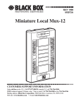
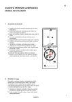
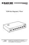
IC207A/8A-Manual
7/12/00
9:31 AM
Page 901
JUNE 2000
IC207A
IC208A
Active Star Hub—RJ-11
Active Star Hub—RJ-45
b
Active Star Hu
POWER
CUSTOMER
SUPPORT
INFORMATION
Order toll-free in the U.S. 24 hours, 7 A.M. Monday to midnight Friday: 877-877-BBOX
FREE technical support, 24 hours a day, 7 days a week: Call 724-746-5500 or fax 724-746-0746
Mail order: Black Box Corporation, 1000 Park Drive, Lawrence, PA 15055-1018
Web site: www.blackbox.com • E-mail: [email protected]
IC207A/8A-Manual
7/12/00
9:31 AM
Page 1
SAFETY
Safety
READ THIS FIRST!
1. Do not connect the Active Star Hubs to any type of public network.
2. Do not connect any outdoor cabling to the Active Star Hubs without proper
lightning protection.
3. Do not use unauthorized power supplies or cables with the Active Star Hubs.
4. Do not connect the Active Star Hubs to non-5250 protocol devices.
5. Do not disassemble or modify the power supply and its cables.
6. Do not open the Active Star Hubs that are connected to power or data cables.
Disconnect all cables before configuration.
7. Devices attached to the UTP network must comply with the voltage and
current limits for Class 2 Power-Limited Signal Circuits as defined by article
725 of the National Electrical Code and Section 16 of the Canadian Electrical
Code.
8. For your safety, receptacles must be properly wired and grounded.
9. Never attempt to service equipment connected to the data cable network or
to the grounded receptacle during an electrical storm. Exposure to lethal
voltages may occur when lightning is present.
The following FCC statement applies to the Active Star Hubs.
1
IC207A/8A-Manual
7/12/00
9:31 AM
Page 2
ACTIVE STAR HUB
FEDERAL COMMUNICATIONS COMMISSION
AND
INDUSTRY CANADA
RADIO FREQUENCY INTERFERENCE STATEMENTS
This equipment generates, uses, and can radiate radio frequency energy and if not
installed and used properly, that is, in strict accordance with the manufacturer’s
instructions, may cause interference to radio communication. It has been tested
and found to comply with the limits for a Class A computing device in accordance
with the specifications in Subpart J of Part 15 of FCC rules, which are designed to
provide reasonable protection against such interference when the equipment is
operated in a commercial environment. Operation of this equipment in a
residential area is likely to cause interference, in which case the user at his own
expense will be required to take whatever measures may be necessary to correct the
interference.
Changes or modifications not expressly approved by the party responsible for
compliance could void the user’s authority to operate the equipment.
This digital apparatus does not exceed the Class A limits for radio noise emission from digital
apparatus set out in the Radio Interference Regulation of Industry Canada.
Le présent appareil numérique n’émet pas de bruits radioélectriques dépassant les limites
applicables aux appareils numériques de la classe A prescrites dans le Règlement sur le
brouillage radioélectrique publié par Industrie Canada.
2
IC207A/8A-Manual
7/12/00
9:31 AM
Page 3
NOM STATEMENT
NORMAS OFICIALES MEXICANAS (NOM)
ELECTRICAL SAFETY STATEMENT
INSTRUCCIONES DE SEGURIDAD
1. Todas las instrucciones de seguridad y operación deberán ser leídas antes de
que el aparato eléctrico sea operado.
2. Las instrucciones de seguridad y operación deberán ser guardadas para
referencia futura.
3. Todas las advertencias en el aparato eléctrico y en sus instrucciones de
operación deben ser respetadas.
4. Todas las instrucciones de operación y uso deben ser seguidas.
5. El aparato eléctrico no deberá ser usado cerca del agua—por ejemplo, cerca
de la tina de baño, lavabo, sótano mojado o cerca de una alberca, etc..
6. El aparato eléctrico debe ser usado únicamente con carritos o pedestales que
sean recomendados por el fabricante.
7. El aparato eléctrico debe ser montado a la pared o al techo sólo como sea
recomendado por el fabricante.
8. Servicio—El usuario no debe intentar dar servicio al equipo eléctrico más allá
a lo descrito en las instrucciones de operación. Todo otro servicio deberá ser
referido a personal de servicio calificado.
9. El aparato eléctrico debe ser situado de tal manera que su posición no
interfiera su uso. La colocación del aparato eléctrico sobre una cama, sofá,
alfombra o superficie similar puede bloquea la ventilación, no se debe colocar
en libreros o gabinetes que impidan el flujo de aire por los orificios de
ventilación.
10. El equipo eléctrico deber ser situado fuera del alcance de fuentes de calor
como radiadores, registros de calor, estufas u otros aparatos (incluyendo
amplificadores) que producen calor.
11. El aparato eléctrico deberá ser connectado a una fuente de poder sólo del
tipo descrito en el instructivo de operación, o como se indique en el aparato.
3
IC207A/8A-Manual
7/12/00
9:31 AM
Page 4
ACTIVE STAR HUB
12. Precaución debe ser tomada de tal manera que la tierra fisica y la polarización
del equipo no sea eliminada.
13. Los cables de la fuente de poder deben ser guiados de tal manera que no
sean pisados ni pellizcados por objetos colocados sobre o contra ellos,
poniendo particular atención a los contactos y receptáculos donde salen del
aparato.
14. El equipo eléctrico debe ser limpiado únicamente de acuerdo a las
recomendaciones del fabricante.
15. En caso de existir, una antena externa deberá ser localizada lejos de las lineas
de energia.
16. El cable de corriente deberá ser desconectado del cuando el equipo no sea
usado por un largo periodo de tiempo.
17. Cuidado debe ser tomado de tal manera que objectos liquidos no sean
derramados sobre la cubierta u orificios de ventilación.
18. Servicio por personal calificado deberá ser provisto cuando:
A: El cable de poder o el contacto ha sido dañado; u
B: Objectos han caído o líquido ha sido derramado dentro del aparato; o
C: El aparato ha sido expuesto a la lluvia; o
D: El aparato parece no operar normalmente o muestra un cambio en su
desempeño; o
E: El aparato ha sido tirado o su cubierta ha sido dañada.
4
IC207A/8A-Manual
7/12/00
9:31 AM
Page 5
TRADEMARKS
TRADEMARKS USED IN THIS MANUAL
IBM® and AS/400® are registered trademarks of International Business Machines
Corporation.
Any other trademarks mentioned in this manual are acknowledged to be the
property of the trademark owners.
5
IC207A/8A-Manual
7/12/00
9:31 AM
Page 6
ACTIVE STAR HUB
Contents
1. Specifications . . . . . . . . . . . . . . . . . . . . . . . . . . . . . . . . . . . . . . . . . . . . . . . . . . . . 7
2. Introduction. . . . . . . . . . . . . . . . . . . . . . . . . . . . . . . . . . . . . . . . . . . . . . . . . . . . . 8
2.1 Description . . . . . . . . . . . . . . . . . . . . . . . . . . . . . . . . . . . . . . . . . . . . . . . . . . . 8
2.2 Features . . . . . . . . . . . . . . . . . . . . . . . . . . . . . . . . . . . . . . . . . . . . . . . . . . . . . 8
2.3 What the Package Includes . . . . . . . . . . . . . . . . . . . . . . . . . . . . . . . . . . . . . . 9
2.4 Typical Application . . . . . . . . . . . . . . . . . . . . . . . . . . . . . . . . . . . . . . . . . . . . 9
3. Active Pair Setup . . . . . . . . . . . . . . . . . . . . . . . . . . . . . . . . . . . . . . . . . . . . . . . . 10
4. Indicators and Connectors . . . . . . . . . . . . . . . . . . . . . . . . . . . . . . . . . . . . . . . . 13
5. Installation . . . . . . . . . . . . . . . . . . . . . . . . . . . . . . . . . . . . . . . . . . . . . . . . . . . . . 14
6. Troubleshooting . . . . . . . . . . . . . . . . . . . . . . . . . . . . . . . . . . . . . . . . . . . . . . . . 15
6
IC207A/8A-Manual
7/12/00
9:31 AM
Page 7
CHAPTER 1: Specifications
1. Specifications
Number of Host Ports—2
Number of Device Ports—14
Data Rate—1 Mbps
Protocol—IBM 5250
Indicators—(17) LEDs: (1) Power, (2) Host Port Activity, (14) Device Port
Activity
Connectors—IC207A: (16) RJ-11; IC208A: (16) RJ-45
Active Pair—Configurable
Maximum Distance—Controller to Hub: Up to 2000 ft. (609.6 m);
Hub to Device: Up to 2200 ft. (670.6 m)
Temperature Tolerance—Operating: 32 to 104°F (0 to 40°C);
Storage: 32 to 185°F (0 to 85°C)
Humidity—95% noncondensing
Power—100 to 240 VAC, +5 VDC, external power supply
Size—1.75"H (1U) x 19"W x 6"D (4.4 x 48.3 x 15.2 cm)
Weight—6.3 lb. (2.9 kg)
7
IC207A/8A-Manual
7/12/00
9:31 AM
Page 8
ACTIVE STAR HUB
2. Introduction
2.1 Description
The IBM® 5250 Express protocol, capable of TCP/IP support, is quickly becoming
the “de facto” standard for AS/400® 5250 PC emulation. With the Active Star Hub
from Black Box, you’re guaranteed an upgrade path (via firmware) to the new
protocol for far less cost than completely replacing the hub.
The Hub is a state-of-the-art dual active star that has two host-port connections
and 14 device-port connections. It was designed with protocol-transparent criteria
and is available with either RJ-11 or RJ-45 connectors. This standards-based, flexible
UTP star solution is a low-cost alternative to expensive and rigid twinaxial
daisychain cabling. Each device port is isolated, assuring that problems won’t be
transmitted throughout the entire network. Digital Phase Lock Loop and signal
conditioning, noise suppression, and proven interoperability assure reliable and
transparent connections with all models of IBM AS/400, 3X, and compatible
terminals, printers, emulation cards, and remote controllers.
2.2 Features
• Proven interoperability with 5250 compatibles.
• Standards-based 5250 “star” hub distribution allows greater flexibility for adds,
moves, and changes.
• Meets or exceeds EIA/TIA wiring recommendations.
• Advanced noise filtering and signal conditioning allows the use of lesser-grade
cabling systems.
• Polarity insensitive as long as host and device polarities are the same.
• Guaranteed firmware upgrade path to the IBM 5250 Express protocol for up
to 800% throughput enhancement.
8
IC207A/8A-Manual
7/12/00
9:31 AM
Page 9
CHAPTER 2: Introduction
2.3 What the Package Includes
Your package should include the following items:
• Active Star Hub RJ-11 (IC207A) or Active Star Hub RJ-45 (IC208A)
• 100-240 VAC input external power supply (attached to Hub)
• This users’ manual
If anything is missing or damaged, please contact Black Box at 724-746-5500.
CAUTION
Do not apply power to any damaged component!
2.4 Typical Application
AS/400
Active
Star
Hub
CAT5 350-MHz
Patch Cable
AS/400
Mini Twinax
to Twisted
Pair Baluns
Figure 2-1. Typical Application.
NOTE
Each device is on a dedicated cable offering complete isolation from
other devices. A single device problem cannot affect other users.
9
IC207A/8A-Manual
7/12/00
9:31 AM
Page 10
ACTIVE STAR HUB
3. Active Pair Setup
IMPORTANT!
If you haven’t already done so, please read the safety guidelines listed
on page 1.
The factory default active pair setting for the Active Star Hub is pins 4/5. The
default and other possible configurations are shown on the identification label
located on the rear panel.
MODEL xxxxxx
PINS 4/5 3/6 1/2
S/N xxxxxxxxxx
Figure 3-1. Identification Label.
You can reconfigure the active pair by following this procedure:
1. Disconnect all power to the unit.
2. Remove the top cover screws located on the rear panel.
3. Gently slide the top cover back one inch.
4. Hold the top cover and tilt it up.
5. Reconfigure the jumpers (located behind the RJ connectors on the circuit
board) as required. Settings for polarity and active pair assignment are shown
in Figure 3-2. All jumper settings must be identical.
10
IC207A/8A-Manual
7/12/00
9:31 AM
Page 11
CHAPTER 3: Active Pair Setup
RJ/11 3/4
RJ-45 4/5
RJ-11
RJ-45
2/5
3/6
RJ-45
1/2
Normal Polarity
Reverse Polarity
Figure 3-2. Active Pair Jumper Settings.
6. To reinstall the top cover, tilt the top cover down. Slide the top cover forward
until it mates completely with the bottom cover.
7. Install the top cover screws.
Figures 3-3 through 3-8 show each of the individual jumper setting described in
Figure 3-2.
Figure 3-3. Jumper Setting for Normal Polarity: RJ-11 pins 3 and 4 or RJ-45
pins 4 and 5.
Figure 3-4. Jumper Setting for Reverse Polarity: RJ-11 pins 3 and 4 or RJ-45
pins 4 and 5.
11
IC207A/8A-Manual
7/12/00
9:31 AM
Page 12
ACTIVE STAR HUB
Figure 3-5. Jumper Setting for Normal Polarity: RJ-11 pins 2 and 5 or RJ-45
pins 3 and 6.
Figure 3-6. Jumper Setting for Reverse Polarity: RJ-11 pins 2 and 5 or RJ-45
pins 3 and 6.
Figure 3-7. Jumper Setting for Normal Polarity: RJ-45 pins 1 and 2.
Figure 3-8. Jumper Setting for Reverse Polarity: RJ-45 pins 1 and 2.
12
IC207A/8A-Manual
7/12/00
9:31 AM
Page 13
CHAPTER 4: Indicators and Connectors
4. Indicators and Connectors
Active Star Hub
POWER
Power
LED
Host
Activity LED
and
connection
Host
Device
Activity LEDs Activity LED
and
and
connections connection
Device
Activity LEDs
and
connections
Figure 4-1. Front Panel of the Hub.
Table 4-1. LED Indicators and Connectors
Indicator or Connector
Function
Host Activity LED
Lights green when a signal is present in the host jack.
Device Activity LED
Lights green when a signal is present in a device jack.
Host Connector
UTP connection for the host (RJ-11 or RJ-45).
Device Connector
UTP connection for the device (RJ-11 or RJ-45).
IIIIIIIIIIIIIIIIIIIIIIIIIIIIII
IIIIIIIIIIIIIIIIIIIIIIIIIIIIII
DC Power
connection
Product
identification
label
FCC label
External
power supply
Figure 4-2. Rear Panel of the Hub.
13
IC207A/8A-Manual
7/12/00
9:31 AM
Page 14
ACTIVE STAR HUB
5. Installation
IMPORTANT!
If you haven’t already done so, please read the safety guidelines listed
on page 1.
1. The Active Star Hub is designed to be placed in a 19" rack. The unit should
be properly installed using all four mounting holes. Rack hardware is not
provided. (For more information on rack hardware that will work with this
unit, call Black Box Technical Support at 724-746-5500.) We recommend that
you use plastic or nylon washers under mounting screws to protect the Hub’s
finish.
2. The external power supply is mounted on the rear panel of the Active Star
Hub. Insert the AC power cord firmly into the external Power supply.
3. Insert the male end of the AC power cord into a properly wired receptacle.
All data and mode LEDs on the Active Star Hub will light for two seconds and
fade. The amber Power LED on the front panel and the green Power LED on
the top of the external power supply will light and remain on.
4. The devices attached to each star segment must have unique addresses.
Connect all the devices to the Hub’s jacks. The LEDs may momentarily blink
as cables are attached. All Device Activity LEDs should be off. If any Device
Activity LED remains on or flashes, refer to Chapter 6, Troubleshooting.
5. Connect the host to the host ports of the Active Star Hub. All Activity LEDs
will sequentially light and remain on. If a port and its devices are Expressready, then the Express data rate will activate and the Express mode LED will
light. If any Activity LED does not remain on or flashes, refer to Chapter 6,
Troubleshooting.
NOTE
The Express and standard modes are mutually exclusive at the port
level. The AS/400 operates a port at the standard rate whenever a
standard rate device is detected. The AS/400 operates in the Express
mode when all of the attached devices are Express capable.
14
IC207A/8A-Manual
7/12/00
9:31 AM
Page 15
CHAPTER 6: Troubleshooting
6. Troubleshooting
If you have problems with your Active Star Hub, follow the suggestions described in
this chapter.
1. Collect all information relevant to this application, including:
• Product serial numbers.
• Host type and operating system software level.
• Quantity and type of peripheral devices.
• Interconnecting cable types and distances.
• Equipment environment.
• Interconnection diagram.
2. Set up the application with the Active Star Hub in one room interconnected
with UTP jumpers. Verify the application with a host port and a terminal.
3. Search through the common problems and possible causes provided below.
The Active Star Hub’s front-panel Power LED is off.
• Verify that the AC and DC connections are correct.
• Verify that the AC outlet is functioning correctly.
If the problem persists, observe the status of the external power supply’s LED
and contact Black Box Technical Support at 724-746-5500.
A device is down or unstable.
• Verify that the host’s device type matches the device.
• Verify that the host workstation controller’s capacity has not been exceeded.
• Verify that the device is properly terminated. A peripheral is terminated when
its twinaxial port has two 54.9-ohm resistors located between the “A” phase pin
and earth ground and the “B” phase pin and earth ground. Termination is
provided via a “Y” or “T” cable assembly or by a terminating balun.
• Verify that there are no polarity reversals in the cable.
15
IC207A/8A-Manual
7/12/00
9:31 AM
Page 16
ACTIVE STAR HUB
• Verify that the cable distance does not exceed the Active Star Hub’s
specification.
• Verify that the cable is data grade.
• Verify that the wiring uses natural pairs.
• Verify that the wiring avoids sources of environmental noise.
• Verify that the balun’s pinout matches the Active Star Hub’s pinout.
• Verify that the host side balun’s pinout/polarity match the device side balun’s
pinout/polarity.
Devices interfere with each other.
• Verify that the devices on star segments have unique addresses.
• Verify that all devices are properly terminated.
16
IC207A/8A-Manual
7/12/00
9:31 AM
Page 900
© Copyright 2000. Black Box Corporation. All rights reserved.
1000 Park Drive
•
Lawrence, PA 15055-1018
•
724-746-5500
•
Fax 724-746-0746