1
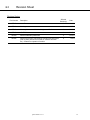
EAGLE TUGS OPERATIONS MANUAL VEHICLE TYPES: ALL TT MODELS WITH SAUER-DANFOSS DISPLAY TT QA044 REV05 9.4.14 QA044 REV05 9.4.14 TT Safety Warning Read this manual in its entirety before putting your Eagle tow tractor into service. This manual contains important safety instructions. Improper usage or a failure to follow the safety requirements listed in this manual could result in severe injury or death. TT QA044 REV05 9.4.14 0-1 Table of Contents 1-1 0-1 Safety Warning 1-1 Table of Contents 2-1 Revision Sheet 3 Introduction 4 5 6 7 3-1 Welcome 3-2 Contact Info 3-3 Warranty 3-4 Proper Use 3-5 Vehicle Weights, Performance, and Specifications Putting the Tow Tractor Into Service 4-1 Unpacking/Setting Up 4-2 Fuel Requirements Instructions for Safe Use 5-1 General Safety Guidelines 5-2 Operator Requirements 5-2 Operator Workstation 5-3 Pre-Operation Inspection 5-4 Sauer Display Panel 5-5 Instrumentation 5-6 Controls 5-7 Starting/Shutdown 5-8 Transmission 5-8 Braking 5-9 Parking Instructions for safe towing/pushing a load 6-1 Towing 6-1 Pushing Instructions for safe handling 7-1 Emergency Towing 7-2 Tie-Down Procedure QA044 REV05 9.4.14 TT Table of Contents 8 Instructions for safe maintenance 8-1 Maintenance Operator Requirements 8-2 General Safety Guidelines 8-3 Daily operator responsibilities Proper Fluid Checks Pre-Operation Checklist TT QA044 REV05 9.4.14 1-1 2-1 Revision Sheet Revision History Rev Number Affected Section(s) Description Date REV00 Initial Release All 1/11/09 REV01 Wording All 2/27/10 REV02 Warranty Statement & Vehicle Weights and Performance 3 01/06/12 REV03 USAT Reference All 02/15/12 REV04 Removed Warranty Statement 3 11/18/13 REV05 Removed preventive maintenance schedule and filter guide (refer to parts and service manual for schedule and filter list). Created Pre-operation Checklist. 8 9/4/14 QA044 REV05 9.4.14 TT Introduction 3-1 W elcome Welcome to the growing family of EAGLE tractor operators. The tractor was built with the operator's safety, comfort and ease of operation in mind. We hope you agree and enjoy your EAGLE experience. Purpose & Use of Manual This manual is designed as a quick guide to familiarize you with the correct and safe operation of your Eagle vehicle as well as to inform you of the preventative maintenance and servicing recommendations of the manufacturer. Your EAGLE vehicle was designed to do very specific tasks. For that reason, it will look, feel, drive and function differently than over-the-road trucks and automobiles, as well as various other types of vocational vehicles. It is the operator’s responsibility to operate this equipment in a safe and prudent (good sound judgment) manner. Be alert, your and other’s safety is involved. The descriptions and specifications contained in this manual were in effect at the time the manual was printed. EAGLE TUGS reserves the right to discontinue models at any time and/or to change specifications, designs or components used without notice and without incurring obligations. TT QA044 REV05 9.4.14 3-2 Introduction Contact Information Corporate Offices Sales, Support, Customer Service Eagle Industrial Truck 26111 Northline Rd Taylor, MI 48180 USA (734) 442-1000 — (800) 671-0431 Website www.eagletugs.com contains useful sales and service information. Please refer to this website for the latest revision of this and all other manuals. Email Addresses Customer Service [email protected] Parts Department [email protected] Technical Support [email protected] Sales Department [email protected] QA044 REV05 9.4.14 TT Introduction 3-3 W arranty Please read the Eagle Tugs warranty statement (available on our website) carefully. Before contacting Eagle Industrial Truck for any warranty issue please have the following information ready: Truck Model Truck Serial Number Engine Type Engine Make Engine Serial Number Hours Reading All information can be found on the data plate located beside the driver seat with the exception of the hours which can be read using the Sauer display or the hour meter on the dash. W arranty Registration Vehicles powered by a Yanmar engine should register the engine by entering the required information into the Customer registration screen found on Yanmar’s website at http://www.yanmar.co.jp. Vehicles powered by a Wisconsin Motors TME27 engine should contact Eagle directly if prior to warranty work being performed for information on the nearest Wisconsin Motors distributor in your area. Warranty registration for your Eagle tractor can completed by visiting our website at www.eagletugs.com. Tires For tire warranty please contact Eagle directly by phone at 800-671-0431, by email at [email protected] or through our website at www.eagletugs.com. Battery In the U.S. and Canada, call 1-888-823-0954 or 1-877-255-2287 TT QA044 REV05 9.4.14 Introduction 3-4 Proper Use of TT Series Tow Tractors The TT line of tow tractors is designed to be an aircraft tow tractor. When used properly in this application, the TT line of tow tractors will provide years of safe operation. The following activities fall within the approved and anticipated usage: Aircraft Towing Aircraft Push-back Travel on improved surfaces with minimal slope Never misuse the tow tractor. The tractor has been designed with aircraft towing as the intended usage. Never do any of the following with the tow tractor: ―Horseplay‖ Racing Turn at excessive speed Off-road travel or travel on unimproved surfaces Drive crossways on a slope or turn on a slope QA044 REV05 9.4.14 TT Introduction 3-5 Vehicle Weights and Performance Model Number Year of Manuf. Rated Draw Bar Pull, DBP (lb/N) **Mass (lb/N) TT4 2012 6,700 29,800 4,000 17,800 500 2,200 TT4 AWD 2012 6,400 28,470 4,000 17,800 500 2,200 TT5 2012 8,300 36,900 5,000 22,200 500 2,200 TT5 AWD 2012 7,200 32,030 5,000 22,200 500 2,200 TT6 2012 10,000 44,500 6,000 26,700 500 2,200 TT6 AWD 2012 8,300 36,920 6,000 26,700 500 2,200 TT8 AWD 2012 9,200 40,920 8,000 35,600 500 2,200 TT10 AWD 2012 12,000 53,380 10,000 44,500 500 2,200 TT12 AWD 2012 14,000 62,280 12,000 53,400 500 2,200 Engine Power (hp/kW) Torque (ft-lb/Nm) Wiscon TME27 Gas 80 60 162 220 Wiscon TME27 LPG 80 60 162 220 Yanmar 4TNV98 Diesel 67 50 186 252 Yanmar 4TNV98T Diesel 83 62 234 317 *Note: Engine Models Below No Longer Used In Productions Engine Power (hp/kW) Wiscon TMD27 Diesel Wiscon TMDT27 Diesel Isuzu 66.5 Torque (ft-lb/Nm) 49.6 116 158 80 60 140 190 4JG1 Diesel 62 46 144 195 Isuzu 4JB1 Diesel 70 52 132 179 Isuzu 4JG1T Diesel 83 61 192 260 Chrysler H153 Gas 96 72 119 162 Mitsubishi 6G72 Gas 141 105 172 233 Ford LRG425 Gas 63 47 104 141 Ford ESG642 Gas 125 93 206 279 **Weight will vary depending on options. TT Rated Vertical Hitch Load (lb/N) QA044 REV05 9.4.14 3-5 Introduction Operator Vibration Level Data The operator interface vibration levels on the TT-series tug were tested by ISO / IEC 17025 accredited testing lab Kolano and Saha Engineers, Inc. of Waterford, MI, USA. QA044 REV05 9.4.14 TT Introduction 3-5 Sound Level Data The TT-series tow tractor emits the following sound levels: Peak dBA at Workstation Model Cycling Throttle while Stationary Full Throttle Moving Yanmar 4TNV98 and 4TNV98T 95 94 The sound level test was performed in a open area on a flat asphalt surface. Readings were taken at the operator workstation, approximate ear height. The following are the test conditions: SPL Meter: Tandy, model 33-2055 Ambient Environment: 67 dbA Temperature: 50°F / 10°C Dewpoint: 37°F / 2°C Humidity: 63% Barometer: 30.28 in / 1025 hPa EMC Data Electromagnetic radiation and immunity were tested by Jacobs Engineering, at the Milford Proving Ground facility in Milford, MI, USA. Electromagnetic Immunity: Vehicle was subjected to a 60V/m electromagnetic field from 30MHz to 1000MHz. No affects were observed on the functionality or operation of the vehicle. This is in conformance with harmonized standard EN 12895:2000. Electromagnetic Radiation: The vehicle electromagnetic radiation was measured in accordance with harmonized standard EN 12895:2000 at frequencies from 30MHz to 1000MHz. All data was within limits deemed acceptable for use by Eagle Tugs in a ground support equipment application. TT QA044 REV05 9.4.14 Putting the Tow Tractor Into Service 4-1 Unpacking and Setting Up The following directions specify the correct steps that should be taken once you receive delivery of your TT series tow tractor. These steps will ensure that the tow tractor will operate safely. 1. Read this entire manual, paying close attention to the safety requirements laid out in it. 2. During the unloading of your Tractor, you should have noted any shipping damage and reported it to Eagle Tugs and the shipping company. Verify that all components appear to be in order and undamaged. 3. Remove any documentation (including this manual) from where it is secured to the seat. Dispose of the zip ties. 4. Verify correct tire pressure on all tires 5. Fuel the tractor with the correct fuel as specified in section 4-2 of this manual. 6. Your Tow Tractor (if equipped) was shipped with two (TT4-8) or four (TT10-12) removable tie-down rings, If necessary, these rings can be removed using the following directions. Note: you will lose the ability to transport the tractor by removing the tie-down rings. TT4 thru TT8 tractors; The rings can be removed by removing the four bolts/ nuts that secure the hitch and tie-down ring bracket in place. The hitch then needs to be re-secured using the same bolts and torqued to a value of 85/115 ft-lbs/Nm. TT10 thru TT12 tractors; The rings can be removed by removing the four bolts/nuts that secure the tie-down bracket in place. The hardware does not need to be reinstalled. TT10-12 Tie-Down Ring Location TT4-8 Tie-Down Ring Location QA044 REV05 9.4.14 TT Putting the Tow Tractor Into Service 4-2 Fuel Requirements Only use the fuels specified below. Failure to use the indicated fuels could lead to poor performance or unwarranted damage to engine components. As fuel capabilities are subject to change, please refer to www.eagletugs.com for the latest up-to-date notices regarding fuels. Engine TT Fuel Wiscon TME27 Gas 87 Octage Gasoline Wiscon TME27 LPG LPG Yanmar 4TNV98 Tier2 No. 2 Diesel Yanmar 4TNV98T Tier2 No. 2 Diesel Yanmar 4TNV98 Tier3/Stage3A Low Sulfur No. 2 Diesel Yanmar 4TNV98T Tier3/Stage3A Low Sulfur No. 2 Diesel Isuzu 4JB1 No. 2 Diesel Isuzu 4JG1 No. 2 Diesel Isuzu 4JG1T No. 2 Diesel Ford LRG425 87 Octage Gasoline Ford ESG642 87 Octage Gasoline Chrylser H153 Gas 87 Octage Gasoline Mitsubishi G672 87 Octage Gasoline Wiscon TMDT27 Diesel No. 2 Diesel Wiscon TMD27 Diesel No. 2 Diesel QA044 REV05 9.4.14 General Usage 5-1 General Safety The following safety recommendations are not intended to address every possible safety aspect of operating this vehicle, but rather serve as a guide. Eagle has taken extensive measures to make sure the ALL vehicles are designed and tested to be safe when they leave the factory. Modifications made to the vehicle after it leaves the factory can cause the vehicle to be unsafe. In any situation, common sense and caution should always be applied and is ultimately the owner/operator’s responsibility. This tractor is a designed to be a dedicated "WORKING" vehicle. It is not designed for or intended to be used for recreational activities, racing or general "horse play activities". Use for any of these inappropriate activities could result in injury, death or damage to the tractor and surrounding objects. Warning: Failure to comply with the following safety precautions can result in serious injury or death as well as equipment damage. Follow all company, facility and OSHA Safety Rules. If you don't have a copy of these, request a copy from your facility management and review them carefully. Review carefully and understand the appropriate sections of this manual before endeavoring to start or operate this tractor. Be sure that the tractor is equipped with fully functional safety equipment required in the areas it will be operated. Such items as rotating beacons, back-up alarms, etc. are available from EAGLE's Factory or your local EAGLE distributor. Warning: All internal combustion engines give off various fumes and gases when running. Do not start or run the engine in a closed or poorly ventilated building where the exhaust gases can accumulate. Avoid breathing these gases as they may contain poisonous carbon monoxide, which can endanger your health or life if inhaled steadily for even a few minutes. Always do the "PRE-OPERATION INSPECTION" before using the tractor (See "CHECKLIST" following this section of the manual). Do not begin to operate the tractor if it should have defective lights, horn, brakes, steering or tires. Report irregularities immediately to your supervisor and/or the proper maintenance personnel. Never start the tractor's engine while standing on the ground. Start the engine from the operator's seat with the transmission in neutral or park and the parking brake in the "ON" position. QA044 REV05 9.4.14 TT General Usage TT 5-1 Your tractor's seat/s are equipped with retractable seat belts for your safety. Fasten your seat belt and adjust the seat before starting the engine. Be sure the seat belt is fitted snugly around the hips, not around the waist as failure to do so may cause injury in the event of a collision. If your tractor is equipped with a passenger seat, and if it is occupied, be sure that the passenger does not distract you from the safe operation of the tractor. BE ALERT! You (and any passenger) must always keep your arms and legs within the perimeter of the tractor's frame to avoid injury. Keep your foot ON the brake pedal and OFF the accelerator and release the parking brake before shifting the transmission into gear. Before shifting from forward to reverse or reverse to forward, bring the vehicle to a complete stop. Do not shift into gear except when the engine is at idle speed and your foot is on the brake pedal. Before dismounting from the tractor, place the transmission in "PARK" and apply the parking brake. If you have not operated this equipment previously, practice driving and operating it in a safe and clear (not congested) area until you are familiar with all aspects of its operation. Keep hands and feet away from moving mechanical parts including tires. Avoid wearing loose clothing that might get caught in moving parts. Check your path of intended motion for personnel and/or possible obstructions, before proceeding. When operating the tractor, be particularly cautious when in congested areas. Be alert near blind corners and always anticipate other equipment and personnel movements. Sound the horn when approaching corners. Use particular care to operate the vehicle at a safe speed, commensurate with conditions. Speed should always be reduced when entering a turn to assure complete control of the vehicle and any towed loads. Take all corners wide, especially if towing trailers. Speed should always be adjusted to allow for a safe and controlled stop, considering the space available for stopping and the weight of the load being moved. Avoid sudden stops. Reduce speed when approaching speed bumps. Do not tamper with the engine speed governor. Never drive crossways on a slope. Avoid operating on bumpy, soft surfaces. Avoid potholes when present. Keep clear of the edge of loading docks. QA044 REV05 9.4.14 5-2 General Usage Operator Requirements The TT series tow tractor is a piece of industrial equipment and has inherent safety risks. As such, the operator of the tow tractor is expected to have a fork truck or similar license, or be otherwise trained in the usage of material handling equipment. The operator should read this manual fully before operating the tow tractor. The operator should be familiar with all aspects of the tow tractor before operating it. Operator Workstation Your TT series tow tractor features an ergonomically designed operator’s workstation. This is the only operator workstation on the tractor. Do not sit on or stand on the tractor outside of this area. The operator should be seated with the seatbelt secured when starting or moving the tractor. The operator (and any passengers) should keep all extremities within the perimeter of the tractor’s frame to avoid injury. The only time it is appropriate to leave the operator’s compartment when the tractor engine is running is while the tractor is stopped, the transmission gear selector is in park, and the parking brake is applied. QA044 REV05 9.4.14 TT General Usage 5-3 Pre-Operation Inspection Checklist The following inspections should be conducted each day prior to the first operation of the tractor. Additional inspections may be required due to unusual operating conditions Walk-A-Round Inspection - Look for evidence around and under tractor for oil, water or fuel leaks. - Check that fuel cap is securely in place. - Check tire rims and wheel stud nuts for possible damage. - Check tires for under inflation, cuts, breaks or excessive wear and remove any objects stuck in treads. - Wipe clean, if necessary, all lights, mirrors and reflectors. - Open engine compartment hood and check; Oil and coolant levels. Condition of all drive belts (for cracks or fraying). Condition of all wiring, hoses and tubing for leaks, kinks or excessive wear. If tractor is diesel powered, visually check fuel filters and drain the water if necessary Inside Drivers Compartment - With the transmission in PARK and the hand brake set, start the engine. See ―Starting & Shut-Down Procedures‖ in section 5.7. - Check oil pressure and voltage gauges to be sure they are indicate a reading in the normal range. - Check fuel gauge to determine if fuel should be added. - Sound the horn and test for excessive play in the steering wheel. - Turn on all lights and flashers. Then exit tractor to verify they are operating properly. If the tractor is equipped with a rotating beacon, check if it is functioning. - With engine running, check the transmission fluid level under the hood. Warning: Keep hands and clothing away from fans, belts, and any moving parts. TT QA044 REV05 9.4.14 5-3 General Usage Cab Inspection If the tractor is equipped with a cab: - Check that all mirrors are properly adjusted and clean. - Test windshield wiper . - Check all windows for cracks or chips. Be sure windows are clean for best visibility - Check that heater and heater fan are functioning correctly. - Check defrost fan for proper operation. Warning: Any problems noted during inspection should be corrected as soon as possible. Failure to attend to problems promptly could compromise safety and/or the tractor’s performance. Do not attempt to make repairs. Contact a qualified mechanic. QA044 REV05 9.4.14 TT General Usage TT Digital Control Panel: The TT line of tow tractors equipped with Yanmar 4TNV98 engines also feature a Sauer digital display and control unit provided by Sauer-Danfoss. The Sauer display provides many useful features and benefits to the operator. Below, you will find standard operating instructions for the display. Display Screen A B C D Starting the unit: Starting the truck is done with the Sauer display panel. Be sure the transmission is in Park or Neutral and engage the parking brake. Turn the ignition switch to ―ON‖ to provide power to the Sauer display panel. Once powered up, the Sauer display panel will prompt the user to turn the ignition switch to crank the engine. Shutting Down the Unit: Shutting down the unit is as simple as switching the ignition switch to the ―OFF‖ position while the engine is running. TT QA044 REV05 9.4.14 5-4 5-4 General Usage Operation Screen: The Operation Screen is the main screen and provides gauge and other engine/truck operating information. The Operation Screen shows the Fuel level (large center gauge), Oil Pressure (upper right), and Coolant Temperature (upper left) as the three analog gauges. Supplemental information is shown as text at the bottom right corner of the display (engine hours, battery voltage, and engine rpm). The Operation Screen will also show fault codes and warning and informational messages. If a fault code appears, take careful note of it before powering down the tractor. The fault code will be reset after restarting. Supplemental Options: Brightness/Contrast: Press D from the Operation Screen. Use the A and B buttons to adjust the brightness. Use the C and D buttons to adjust the contrast. The display will return to the Operation Screen after 5 seconds without a key press. Units: Press C then B at the same time for 3 seconds to toggle from Imperial to Metric Units. Fault Codes: Press B to from the Operation Screen to view the Engine Fault Screen. This will show active and inactive faults that have occurred since the vehicle was turned on. If you are receiving a fault code, take careful note of it before powering down the tractor. All fault history will be reset after restarting. QA044 REV05 9.4.14 TT General Usage 5-5 Instrumentation Familiarize yourself with all instruments on the tractor. Many are designed to alert you to conditions that must be addressed. When operating the tractor, frequently check gauges to insure everything is functioning as it should be and in the normal range. Oil Pressure Gauge The gauge will vary within the normal operating range of 10-50 psi (69-345 kPa) for gasoline engines (TME27, H153, 6G72, LRG725 and ESG642) and 20-60 psi (138414 kPa) for Diesel engines (4TNV98, 4TNV98T, TMD27, TMDT27, 4JB1, 4JG1 and 4JG1T. If the value drops below the normal range when the engine is running, there is a loss of pressure. If this occurs, stop the tractor as soon as possible, shut off the engine and check the oil level. If your tractor is equipped with a Sauer display, an error will be displayed and the tractor will power down after 15 seconds. Add oil as necessary. Check for possible causes (leaks) for the low oil pressure. If low oil pressure should recur, follow the above directions and contact equipment maintenance personnel to determine cause of recurring low oil pressure. Caution: Do not continue to operate the tractor as long as the oil pressure is below the normal operating range. Continued operation may cause severe internal engine damage. Hour Meter The hour meter indicates the amount of running time on the engine. It is used as a guide as to when preventative maintenance procedures should be done. (See "Preventative Maintenance Schedules" following this section of the manual). Voltage Gauge This gauge indicates the battery voltage available (normally 12-14 volts). After starting the engine, the value should be about 14 volts, which indicates the alternator is working. If the value falls below 12 volts with no accessories operating and the engine running, have the electrical system checked by maintenance personnel. The value may fall below 12 volts at engine idle and accessories operating—shut off all accessories to check that pointer returns to 12 volts or higher while the engine is running. Also by adding a little throttle to increase engine speed, the value should climb back into the correct voltage position. TT QA044 REV05 9.4.14 5-5 General Usage Fuel Gauge The fuel gauge indicates the approximate fuel level in the fuel tank. The reading may fluctuate during starting up, cornering and stopping. It is recommended that the fuel supply be kept at 1/4 or higher levels to prevent any water condensation in the fuel tank from entering the fuel lines. Temperature Gauge This gauge indicates the temperature of the engine coolant. The temperature will rise to the normal range as the engine warms. If the value moves above the normal range of 225°F (107°C), the engine is overheating. If your tractor is equipped with a Sauer display, an error will be displayed and the tractor will power down after 15 seconds. Check for proper airflow through the radiator and that there is not a coolant leak. Running the engine while overheating can cause engine damage. Caution: If the engine continues to overheat, have the cooling system checked. QA044 REV05 9.4.14 TT General Usage 5-6 Controls Ignition Switch (All models without a Sauer display) Your tractor is equipped with either a keyed or keyless ignition switch. Both switches are three-position switches-OFF, ON and START (Crank). ON POSITION - The fuel pump, electrical system, accessories and fueltemperature-voltage gauges are activated. The oil pressure gauge will not fully activate until the engine is started. START POSITION – This is used to start the engine. The engine will crank until you release the ignition switch. When the ignition switch is released in the start position, you must turn the switch to the "OFF" position first before returning to the start position. This is to prevent trying to start the engine when it is already running (anti-restart protection). OFF POSITION - This is used to shut down the engine and turn all electrical power off (including accessories). Never leave the tractor unattended with the engine running or the ignition switch in the "ON" position, as this can result in a run-down battery. Ignition Switch (4TNV98 Engines) Your tractor is equipped with either a keyed or keyless ignition switch. The switch provides power to the Sauer display which is used to start the engine. Headlight switch The headlight switch is an on/off type. There is no hi/low beam control position. Heat Temperature Control (Option) The heat temperature control is a push/pull control cable and is used to adjust the air temperature from the heater in a cab. Pull up to set at desired temperature. Push down to turn heat off. Heater Fan Control Switch (Option) The heater fan switch has three positions, OFF, LOW and HIGH. Windshield Wiper Switch (Option) The windshield wiper switch (located on the wiper motor) has an on/off position. The wiper has only one speed. Defrost Fan Control (Option) The defrost fan motor has a switch built in. The switch has three positions-OFF, LOW and HIGH. TT QA044 REV05 9.4.14 5-7 General Usage Starting & Shut-Down Procedures Never start the tractor's engine while standing on the ground. Start the engine from the operator's seat with the transmission in neutral or park and the parking brake in the "ON" position. Your tractor's seat(s) is/are equipped with retractable seat belts for your safety. Fasten your seat belt and adjust the seat before starting the engine. Be sure seat belt is fitted snugly around the hips, not around the waist as failure to do so may cause injury in the event of a collision. Warning: Seat belts may not offer the operator protection in the event of a rollover. The known incidents of a rollover are extremely rare and may occur in situations of operator misuse. Uses of any vocational equipment should be strictly limited to its intended operation. Your tractor may be equipped with an operator's seat containing a safety pressure switch and/or an operator floor mat containing a safety pressure switch (depending on model and options). If it is, it will automatically shut the engine down anytime the transmission is in gear and the operator is not present in the operator’s workstation. Gasoline/LP Tractors Be sure that the transmission is in "Park" or "Neutral". 1. Turn ignition switch to the "ON" position. 2. Depress accelerator pedal once and release. 3. Turn ignition to the "crank" (Start) position to activate the starter motor. Do not crank the engine more than 10 seconds if it doesn't start. If engine does not start, turn ignition switch off. Turn ignition switch to ―ON‖ position. Depress accelerator pedal twice and release. Turn ignition to the "crank" position to activate the starter motor. 4. As soon as the engine starts, release the ignition switch and allow it to return to the ―ON‖ position to avoid damage to the starter and/or flywheel gear teeth. 5. Allow the engine to warm up for a minute or two. 6. Read all instrument panel gauges to verify they are all within the normal operating ranges defined previously under "Instrumentation". QA044 REV05 9.4.14 TT General Usage 5-7 Diesel Engine (4TNV98) Be sure the transmission is in "Park" or "Neutral". 1. Turn ignition switch to the "ON" position. 2. See ―Starting the Unit‖ in section 5.4. 3. Allow the engine to run at idle speed approximately 6 minutes (1/10 of an hour on the hour meter) to circulate and warm engine oil to a safe operating temperature. 4. To shut down the engine, reduce engine speed to idle if the engine is hot. Allow the engine to idle for several minutes to cool to below 195 degrees. Then turn the ignition switch to ―OFF.‖ Diesel Engine (With Dash Mounted Glow Plug) Be sure the transmission is in "Park" or "Neutral". 1. Turn ignition switch to the "ON" position. 2. Push the Red or Black Rubber button labeled ―Glow Plug‖ on the instrument panel. Hold down for the recommended length of time shown on the chart next to the button, them release. 3. Turn the ignition to the ―Crank‖ position to activate the starter motor. Do not crank the engine more that 10 seconds. If the engine does not start, turn the ignition switch to the ―OFF‖ position and repeat the steps above. 4. Allow the engine to run at idle speed approximately 6 minutes (1/10 of an hour on the hour meter) to circulate and warm engine oil to a safe operating temperature. 5. To shut down the engine, reduce engine speed to idle if the engine is hot. Allow the engine to idle for several minutes to cool to below 195 degrees. Then turn the ignition switch to ―OFF.‖ Note: Diesel Tugs powered by a TMD, TMD27, 4JB1, 4JG1, or 4JG1T engine that are equipped with ―Low Oil / Hi Temp Shutdown System‖ must follow the above start procedure as the system will recognize low oil pressure after 10 to 15 seconds of ignition ―ON‖ position before the starter engages. The ignition must be put back into the ―OFF‖ position to reset the timer or the engine will not attempt to restart. Warning: External starting fluids should not be used in a diesel engine air intake system. The use of these fluids will cause severe internal engine damage. TT QA044 REV05 9.4.14 5-8 General Usage Transmission Operation The transmission is controlled by a "lever type" gearshift located in the instrument panel or console. The control has six selector positions- P (Park), R (Reverse), N (Neutral), D (Drive), 2 (Second) and 1 (First). In entering or leaving a gear position, the lever must be moved past a gate. To do this, place the palm of your hand on the top of the selector lever and reach under with your fingers and grip the release mechanism and pull up (or squeeze). Shift to the desired position and release the selector. 1. Keep your foot ON the brake pedal and OFF the accelerator and release the parking brake before shifting the transmission into gear. 2. Before shifting from forward to reverse or reverse to forward, bring the vehicle to a complete stop. Do not shift into gear except when the engine is at idle speed. 3. Before dismounting from the tractor, place the transmission in "PARK" and apply the parking brake. Parking Brake The parking brake is operated by hand lever action. By pulling back on the lever, you activate and set the brake. Pushing forward will release the brake. The brake is adjustable for braking pressure by rotating the knob on the end of the handle lever. A clockwise direction is used to increase the brake holding pressure and counter clockwise to reduce the pressure. All trucks feature a safety system to protect the parking brake from accidental misuse. Depending on engine type, either the accelerator pedal will not respond when the parking brake is engaged, or the engine will shut off when both the parking brake is engaged and the truck is shifted out of Park or Neutral. Foot Brake The foot brake is power assisted and should be applied with a steady and firm downward pressure. If the power assist should fail, the brakes will still operate mechanically but will require increased foot pressure. Always anticipate that you may have to stop unexpectedly. Speed should always be adjusted to allow for a safe and controlled stop. Adjust your speed based on the surface conditions, the space available for stopping and the weight of the load being moved. Be aware of your surroundings. Always be prepared to stop and avoid sudden stops. Caution: If driving on wet or slippery surfaces, lower speed and allow for more stopping distance. Do not spin the wheels when starting up as this may cause damage to the drive mechanisms. QA044 REV05 9.4.14 TT General Usage 5-9 Your tractor is equipped with both front and rear wheel brakes. The front and rear brakes operate on a dual system-- if one set should fail the operation of the other set will continue. The system has an emergency back up of up to three hard applications of the brakes should both systems fail. Parking Every time you park, apply the hand brake, turn the engine off, turn the ignition switch to "OFF" and return the transmission shift lever to neutral or park position. Do not park where you may block other vehicles paths or movement by emergency vehicles. TT QA044 REV05 9.4.14 6-1 Instructions for Safe Towing/Pushing Load Moving Loads Maximum capacity towing or pushing of loads shall be done with the transmission selector lever in 1(first) or REV (reverse) gears. Caution: Pushing or towing loads in D (Drive) can cause transmission failure Load Towing Safety If towing a load, check to see that: The towed load is securely connected to the hitch of the tractor. Be sure hitch is locked/fastened into the closed position. The towed cargo load is secure and within the exterior frame of the vehicle that is carrying the load. For maximum tractor and load control and stability, as well as towing power, be sure the tongue of the trailer is parallel to the ground when connected to the tractor's hitch. Watch the trailer's rear swing clears any obstructions when cornering. Load Pushing Safety If pushing a load: Be sure the tractor is designed for and intended to be used to push the load. If using the tractor for "pushback" of an aircraft, be sure the tow bar is securely fastened to both the aircraft and the tractor and the tractor hitch is in the locked position. QA044 REV05 9.4.14 TT Handling 7-1 Emergency Towing If it should be necessary to tow the tractor to a location for maintenance service, be sure the following procedures are followed: Make sure the parking brake is released and the transmission gearshift lever is in the "N" (Neutral) position. "ALL WHEEL DRIVE" tractors must have the drive shafts removed before towing. Plug the drive shaft openings to minimize loss of fluid. "REAR DRIVE ONLY" tractors, the rear wheels can be raised and it can be towed on its front wheels. If it is to be flat towed, the drive shaft must be removed. "ANY TRACTOR" towed on its front wheels must have the steering wheel clamped in the straight ahead position. Caution: Replace lost transmission fluid after reinstalling the drive shafts that were removed for towing. Warning: Before working underneath the tractor, be sure jack stands are secure and positioned correctly (perpendicular to the floor) with no tilt. Warning: If you will be working under the tractor, never do so when alone. Be sure someone else is close by in case of an emergency. Warning: If using a hydraulic or air operated lift, always check the safety support or lock is in position before going underneath the tractor. TT QA044 REV05 9.4.14 7-2 Handling Tie Down Procedure For long distance travel, the TT-series tow tractor can be transported by trailer. When transporting the tow tractor, please use the following tie-down procedure. This will ensure that the tractor is securely fastened and will prevent damage to the tractor. 1) Position tractor on trailer, put transmission selector in Park and set Parking Brake. 2) Use correctly sized load chains to secure the tractor to the trailer side tie downs Do not use load straps. 3) Run chain though the tie-down rings (if equipped) located behind the E-hitches. 4) Take both ends of the chain out and down away from the tractor and tighten as required to secure the tractor. 5) Note: chains must not touch front or rear of tractor. Chain contact with the tractor is with the tie-down rings only. 6) Do not top load anything on the tractor. 7) Do not run straps or chain across the top of the tractor. QA044 REV05 9.4.14 TT Maintenance 8-1 Maintenance Operator Requirements Only trained and qualified mechanics familiar with ground support equipment should undertake repairs on the TT series tow tractor. The maintenance operator should read the operator’s manual and the service manual fully before performing maintenance on the tow tractor. Repairs Safety ONLY a trained and qualified mechanic for this type of equipment should undertake repairs to this tractor. Before undertaking any repair, the mechanic MUST read and understand the "SAFETY" and "OPERATING PROCEDURES" sections of this manual. All safety recommendations and rules MUST be followed. TT QA044 REV05 9.4.14 8-2 Maintenance General Safety Guidelines Always stop the tractor, turn the engine off, put in "Park" and apply the parking brake when making any adjustments or servicing the unit. Never refuel the tractor when the engine is running. DO NOT SMOKE WHEN REFUELING. Do not over fill the fuel tank. Do not fill beyond bottom of fuel filler screen. Clean off any spilled fuel immediately. Keep fuel stored well away from open flames, possible sparks or sources of excessively high temperatures. Do not ever remove the radiator cap when the engine is hot, as serious burns may result. Always check coolant level and add coolant at the overflow reservoir. Avoid touching a hot engine, exhaust, coolant pipes or hydraulic components as serious burns may occur. This tractor comes factory equipped with a sealed "maintenance free" battery. Do not endeavor to service the battery. When connecting or disconnecting battery cables, always first remove the cable on the negative terminal (-) and when reconnecting, replace it last. This will prevent sparks from accidental grounding. PREVENT BATTERY EXPLOSIONS. Do not smoke near the battery. Fumes from batteries are explosive. Keep away from all sparks, open flames etc... Remove bracelets; watch bands etc. prior to installing, removing or servicing a battery. Do not short the battery terminals. AVOID ACID BURNS. The battery acid is poisonous and is strong enough to burn skin, eat holes in clothing and cause blindness if splashed in the eyes. If battery acid is spilled or splashed, always immediately wash your skin and clothing. Apply lime or baking soda to help neutralize the acid. Seek medical assistance. QA044 REV05 9.4.14 TT Maintenance 8-2 Important Safety Notice Appropriate service methods and proper repair procedures are essential for the safe, reliable operation of all industrial engines as well as the personal safety of the individual performing the work. This Service Manual provides general directions for accomplishing service and repair work with tested and effective techniques. Following them will help assure reliability. There are numerous variations in procedures, techniques, tools and parts for servicing equipment, as well as in the skill of the individual doing the work. This Manual cannot possibly anticipate all such variations and provide advice or cautions as to each. Accordingly, anyone who departs from the instructions provided in this Manual must first establish he compromises his/her personal safety, and/or the equipment integrity by his/her choice of methods, tools or parts. Warnings The following list contains some general WARNINGS that you should follow when you work on equipment: TT Always wear safety glasses for eye protection. Use safety stands whenever a procedure requires you to be under the equipment. Be sure that the battery is disconnected from the truck using the battery disconnect, unless otherwise required by the procedure. Set the parking brake when working on the equipment. Place wood blocks (4‖ x 4‖ or larger) to the front and rear surfaces of the tires to provide further restraint from inadvertent equipment movement. Operate the engine only in a well-ventilated area to avoid the danger of carbon monoxide. Keep yourself and your clothing away from moving parts when the engine is running, especially the fan and belts. To prevent serious burns, avoid contact with hot metal parts such as the radiator, exhaust manifold, tail pipe, catalytic converter and muffler. Do not smoke while working on the equipment. To avoid injury, always remove rings, watches, loose hanging jewelry, and loose clothing before beginning to work on the equipment. Tie long hair securely behind the head. Keep hands and other objects clear of the radiator and blades. Electric cooling fan(s) can start to operate at any time by an increase in under hood temperatures, even though the ignition is in the OFF position. Therefore, care should be taken to ensure the electric cooling fan(s) are completely disconnected when working under the hood. QA044 REV05 9.4.14 8-3 Maintenance Daily Operator Responsibilities Proper Fluid Checks Engine Oil Check engine oil with the unit on a level surface, the ignition switch in the ―OFF‖ position, the shifter position in ―PARK‖ and parking brake applied. Open side access door or hood depending on engine configuration. Remove dipstick from crankcase, wipe it with a cloth. Insert it fully and take out it gently again. Check the oil level by the marks on the dipstick. The oil level must be between the ―Max‖ level and the ―Min‖ level. DO NOT OVERFILL. Coolant DO NOT remove recovery tank cap or check coolant level while engine is hot! With engine cool, the ignition switch in the ―OFF‖ position, the shifter position in ―PARK‖ and the parking brake applied, open hood, set hood prop and look at left side of recovery tank. The reservoir tank is translucent, so the fluid is readily visible without removing the cap. Fluid level should be at the ―Cold fill level‖. Transmission Fluid With unit in park and parking brake set in the ―ON‖ position, start engine. Open side access door. Remove dipstick from transmission case, wipe it with a cloth. Insert it fully and take it out gently again. Check the fluid level by the marks on the dipstick. The transmission fluid level must be between the ―Max‖ level and the ―Min‖ level on the dipstick. DO NOT OVERFILL. Brake Fluid Check brake fluid with the unit on a level surface, the ignition switch in the ―OFF‖ position, the shifter position in ―PARK‖ and parking brake applied. Open hood, set hood prop and locate master cylinder reservoir. Remove spring clips and take off lid. Brake fluid level should be at the top of reservoir. Power Steering Fluid Check power steering fluid with ignition switch in ―OFF‖ position, the shifter position in ―PARK‖ and the parking brake applied. Open hood, set hood prop remove cap from power steering reservoir. Fluid level should be between the arrows on the indicator stick. DO NOT OVERFILL. QA044 REV05 9.4.14 TT Maintenance 8-3 Pre-Operation Inspection Checklist The following inspections should be conducted as stated below. Additional inspections may be required due to unusual operating conditions. Daily Pre-Operation Checklist Satisfactory Service Not Required Applicable Satisfactory Service Not Required Applicable Walk-around inspection Verify no evidence of leaks under and around the tractor Verify fuel cap securely in place Visually verify tires are fully inflated Verify rims and tires free from damage including tire tread Verify tire tread is free from debris Verify lights, mirrors, and reflectors are clean Operational Checks (tractor engine running) Verify that the dash panel is free of errors and warnings Verify that oil pressure is in the normal operating range Verify that battery voltage is in the normal operating range Verify that horn is operational Verify that lights, flashers, and beacon (if equipped) work properly Cab Inspection (if equipped) Verify windows clean Verify windows free of cracks and chips Verify windshield wipers operate properly Verify heater and fans operate properly Weekly Operation Checklist Walk-around inspection Check to verify tires are properly inflated Engine Compartment Inspection Check engine oil level (top off in necessary) Check engine coolant level (top off if necessary) Check power steering fluid level (top off if necessary) Drain water from fuel/water separator (if equipped) Verify wiring, hoses, and tubing free of leaks and damage Remove dust from air cleaner dust valve Warning: Any problems noted during inspection should be corrected as soon as possible. Failure to promptly attend to problems could compromise safety and/or the tractor’s performance. Do not attempt to make repairs. Contact a qualified mechanic. TT QA044 REV05 9.4.14 Safety Procedure Review Signature Sheet By signing below you are verifying that you have read and understand the contents of this manual. Date: Printed Name: QA044 REV05 9.4.14 Signature: TT