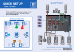
1
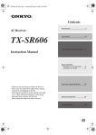
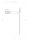
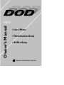
Owner’s Manual
SR606
• Line Mixer
• Distribution Amp
• Buffer Amp
A Harman International Company
Warning
For your protection, please read the following:
Water and Moisture: Appliances should not be used near water
(e.g. near a bathtub, washbowl, kitchen sink, laundry tub, in a wet
basement, or near a swimming pool, etc.) Care should be taken so
that objects do not fall and liquids are not spilled into the enclosure
through openings.
These symbols are internationally accepted symbols that warn of potential
hazards with electrical products.The lightning flash means that there are
dangerous voltages present within the unit.The exclamation point indicates
that it is necessary for the user to refer to the owners manual.
These symbols warn that there are no user serviceable parts inside the unit.
Do not open the unit. Do not attempt to service the unit yourself. Refer all
servicing to qualified personnel. Opening the chassis for any reason will void
the manufacturer’s warranty. Do not get the unit wet. If liquid is spilled on
the unit, shut it off immediately and take it to a dealer for service.
Disconnect the unit during storms to prevent damage.
U.K. Mains Plug Warning
A molded mains plug that has been cut off from the cord is unsafe.
Discard the mains plug at a suitable facility. Never under any circumstances should you insert a damaged or cut mains plug into a 13
amp power socket. Do not use the mains plug without the fuse cover
in place. Replacement fuse covers can be obtained from your local retailer. Replacement fuses are 13 amps and MUST be ASTA approved to
BS1362.
Power Sources: The appliance should be connected to a power
supply only of the type described in the operating instructions or as
marked on the appliance.
Grounding or Polarization: Precautions should be taken so that
the grounding or polarization means of an appliance is not defeated.
Power Cord Protection: Power supply cords should be routed so
that they are not likely to be walked on or pinched by items placed
upon or against them, paying particular attention to cords at plugs,
convenience receptacles, and the point where they exit from the
appliance.
Servicing: To reduce the risk of fire or electrical shock, the user
should not attempt to service the appliance beyond that described in
the operating instructions. All other servicing should be referred to
qualified service personnel.
For units equipped with externally accessible fuse receptacle: Replace fuse with same type and rating only.
Safety Instructions
Electromagnetic Compatibility
Notice for customers if your unit is equipped with a power cord.
Operation is subject to the following conditions:
•This device may not cause harmful interference.
•This device must accept any interference received, including
interference that may cause undesired operation.
•Use only shielded interconnecting cables.
•Operation of this unit within significant electromagnetic fields
should be avoided.
Warning:This appliance must be earthed.
The cores in the mains lead are colored in accordance with the following
code:
Green and Yellow - Earth Blue - Neutral
Brown - Live
As colors of the cores in the mains lead of this appliance may not correspond with the colored markings identifying the terminals in your plug, proceed as follows:
•The core which is colored green and yellow must be connected to the
terminal in the plug marked with the letter E, or with the earth symbol, or colored green, or green and yellow.
•The core which is colored blue must be connected to the terminal
marked N, or colored black.
•The core which is colored brown must be connected to the terminal
marked L, or colored red.
This equipment may require the use of a different line cord, attachment
plug, or both, depending on the available power source at installation. If the
attachment plug needs to be changed, refer servicing to qualified service
personnel who should refer to the table below.The green/yellow wire shall
be connected directly to the units chassis.
CONDUCTOR
L
LIVE
WIRE COLOR
Normal
Alt
BROWN
BLACK
N
NEUTRAL
BLUE
WHITE
E
EARTH GND
GREEN/YEL
GREEN
Warning: If the ground plug is defeated, certain fault conditions in the unit
or in the system to which it is connected can result in full line voltage
between chassis and earth ground. Severe injury or death can then result if
the chassis and earth ground are touched simultaneously.
SR606
INTRODUCTION
Congratulations, and thank you for your purchase of the DOD SR606 Line
Mixer/Distribution Amp.
The DOD SR606 is one of the most flexible sound reinforcement tools available on the market today. It can be used as a distribution amp, line mixer,
buffer amp, or any combination of the three.
The SR606 is laid out in a logical and simplistic format. Each channel has its
own level and pan control.The stereo inputs and stereo outputs have their
own level adjustment as well.
This Owner’s Manual is your guide to understanding how to get the most out of
the SR606. Please read it carefully and familiarize yourself with the controls on
the SR606. By doing so, you will open a world of audio solutions to multiple
applications.
Your SR606 was carefully assembled and packaged at the factory. Before continuing any further, please make sure the following items have been included:
1 SR606
1 Owners Manual
1 Warranty Card
1 Detachable Power Cord
Please take a moment to fill out the warranty card. It is your safe guard in the
unlikely event that your unit requires servicing. Please save all packing materials
and use these materials to return the product if servicing is required.
1
2
SR606
FRONT PANEL
3
1
2
4
5
6
1. Master Input Level - Controls the signal strength entering the Left and
Right Inputs.
2. Channel 1-6 Level - Controls the signal strength entering the 1-6 inputs,
being delivered to the 1- 6 Outputs, or being delivered to the Left and Right
Outputs, depending on your application.
3. Channel 1-6 Pan - Controls the Left/Right position being delivered from
Channels 1-6 to the Stereo Outputs, or Selects which Stereo Input Channel 1-6
is receiving its signal from.
4. Master Output Level - Controls the signal strength being delivered to the
Left and Right Outputs.
5. Clip LEDs - These LEDs light 3 dB before clipping occurs at the Left or Right
Outputs only.
NOTE: The clip indicators will only register clipping at the outputs.They will
not register a clip at any other point in the unit.
6. Power Switch - Used to engage or disengage the power to the SR606.
SR606
REAR PANEL
4
1
2
3
5
6
1. Power Receptacle - Connect the detachable Power cord from here to an
AC outlet
2. Main Output - These Left and Right Outputs can receive signal from the
Left and Right Inputs, or the Channel 1-6 Inputs, or a combination, depending on
your application.
3. Channel 1- 6 Outputs - The Channel 1-6 Outputs can receive signal from
the Main Inputs, or from the Channel 1- 6 Inputs, or a combination, depending
on your application.
4. Channel 1 - 6 Mix/Dist Switch - These switches selects individual Channels
of the SR606 to be used as a distribution amp, or as a line mixer. When the
switches are depressed, the SR606 will act as a distribution amp. When the
switches are not depressed, the SR606 will act as a line mixer.
NOTE: If using the SR606 as a line mixer, make sure that all switches are out.
This will prevent the unit from self oscillating.
5. Channel 1 - 6 Inputs - These are the Inputs for Channel’s 1 - 6, which can
be routed to the Left and Right Outputs, or the Channel 1- 6 Outputs, or a combination, depending on your application.
6. Main Inputs - These Left and Right Inputs can deliver their signal to the
Channel 1 - 6 Outputs, the Left and Right Outputs, or a combination, depending
on your application.
3
4
SR606
INSTALLATION
Install the SR606 in a rack with the provided rack screws. Route the AC power
cord to a convenient power outlet away from audio lines. The unit may be
turned on and off using the front panel power switch. Since the units draw a relatively small amount of current during idle, they can be left on continuously.
The DOD SR606 generates very little heat during operation and thus does not
need to be specially ventilated or cooled. The unit should not, however, be subjected to high temperatures for extended periods. Although the unit's chassis is
shielded against radio frequency and electromagnetic interference, extremely
high RF and EMI fields should be avoided.
Once the SR606 has been installed and adjusted for the required levels, an
optional security panel can be installed to keep unauthorized persons from
changing the settings.
FUNCTIONS
The SR606 can be used as a Line Mixer, a Distribution Amp, a Buffer Amp, or
any combination of the three.The following sections outline the set up procedure for all three applications, and define the functions of the knobs for each.
LINE MIXER
To use the SR606 as a line mixer, simply connect each of your source signals to
the Channel 1 - 6 Inputs.You may also connect a source signal to the Left/Right
Main Inputs.
Connect the Left/Right Main Outputs to your power amp, or other destination.
The front panel Channel 1 - 6 Level controls will determine the amount of signal to be sent to the Left/Right Main Outputs.
The Channel 1 - 6 Pan controls will determine the position in the stereo field.
The Master Input Level will control the amount of signal reaching the Main
Outputs from the Main Inputs.
The Master Output Level will control the overall signal being sent out of the
Left/Right Main Outputs
SR606
DISTRIBUTION AMP
To use the SR606 as a distribution amp connect your source signal to either
the Left, Right, or Left and Right Inputs.
Connect as many of the 1 through 6 Outputs as desired.You may also use the
Left and Right Outputs for a total of 8 Outputs.
The signal coming in to the Left/Right Inputs will be delivered to the 1 through
6 Channel Outputs.
The Level control of each Channel will adjust the volume at each individual
Channel Output.
The Pan control of each Channel will select which Input (Left/Right) the signal
is being taken from.
The Master Output will only affect the signal strength at the Left/Right
Outputs.
In this mode the SR606 can be used as a mono in with six outputs, or a dual
mono in with as many outputs (up to 4 for each mono input) as you desire.
BUFFER AMP
To use the SR606 as a buffer amp, connect your source signals to as many of
the 6 Inputs as needed.
Connect as many of the 6 Outputs as needed.This should coincide with the
number of Inputs.
The Channel Level knobs will now attenuate, or provide up to a 4 dB boost in
gain to the signal(s) being sent to the corresponding Outputs.
MAINTENANCE AND SERVICING
There are NO user serviceable parts inside the units. Opening the chassis will
void the warranty. All service and repair must be performed by the factory or
an authorized service center for the warranty to remain in service.
Should a problem arise with the equalizer, please contact your authorized DOD
Electronics dealer for return/repair procedures.
5
6
SR606
SPECIFICATIONS
Input Connectors:
Input Impedance:
Maximum Input Level:
Input Gain:
Output Connectors:
Output Impedance:
Maximum Output Level:
Frequency Response:
THD+N:
SNR:
Dynamic Range:
8 1/4” TRS balanced
20K balanced
22dBu
-98dB to +6dBu
8 1/4” TRS balanced
200 ohms balanced
22dBu
10Hz. to 22KHz.
.015% Ref. +4dBu @ 1KHz.
90dB to mix outputs
108dB
DOD WARRANTY
1. The warranty registration card must be mailed within ten days after purchase
date to validate this warranty.
2. DOD warrants this product, when used solely within the U.S., to be free from
defects in material and workmanship under normal use and service.
3. DOD Electronics liability under this warranty is limited to repairing or replacing defective materials that show evidence of defect, provided the product is
returned through the original dealer, where all parts and labor will be covered
up to a period of three (3) years. The company shall not be responsible for any
consequential damage as a result of the products use in any circuit or assembly.
4. Proof of date of purchase is considered to be the burden of the consumer.
5. DOD reserves the right to make changes in design or make improvements
upon this product without incurring any obligation to install the same on PRODUCTS PREVIOUSLY MANUFACTURED.
6. The foregoing is in lieu of all other warranties, either expressed or implied,
and DOD neither assumes nor authorizes any person to assume for it any obligation or liability in connection with the sale of this product. In no event shall
DOD or its dealers be liable for special or consequential damages or from any
delay in the performance of this warranty due to causes beyond their control.
DECLARATION OF CONFORMITY
Manufacturer’s Name: DOD Electronics
Manufacturer’s Address: 8760 S. Sandy Parkway
Sandy, Utah 84070
declares that the product:
Product Name:
SR606
Product Options:
All
conforms to the following product specifications:
Safety:
EN 60065 (1993)
IEC65(1985) with Amendments 1, 2, 3
EMC:
EN 55013 (1990)
EN 55020 (1991)
Supplementary Information:
The product herewith complies with the requirements of the Low voltage
directive 73/23/EEC and the EMC Directive 89/336/EEC as amended by
directive 93/68/EEC.
DOD Electronics
President
8760 S. Sandy Parkway
Sandy, Utah 84070, USA
Effective (9/28/98)
European Contact: Your Local DOD Sales and Service Office or
International Sales Office
8760 S. Sandy Parkway
Sandy, Utah 84070, USA
Tel (801) 568-7638
Fax (801) 568-7642
V ISIT DOD E LECTRONICS ON THE WORLD W IDE W EB
HTTP :// WWW. DOD. COM
AT
DOD E LECTRONICS C ORPORATION
8760 S OUTH S ANDY PARKWAY
S ANDY, U TAH 84070
T ELEPHONE 801-566-8800
FAX 801-566-7005
I NTERNATIONAL D ISTRIBUTION
8760 S OUTH S ANDY PARKWAY
S ANDY, U TAH 84070
T ELEPHONE 801-568-7638
FAX 801-568-7642
DOD
IS A
R EGISTERED T RADEMARK
OF
H ARMAN M USIC G ROUP I NC .
© 1998 DOD E LECTRONICS C ORPORATION
DOD 18-2281-B