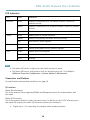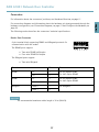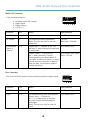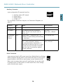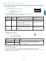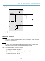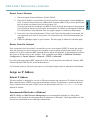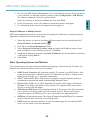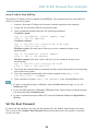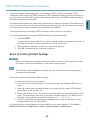
1
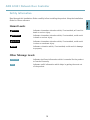
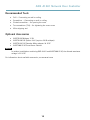
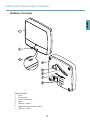
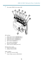
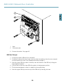
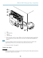
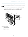
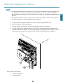
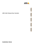
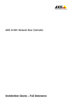
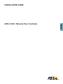
INSTALLATION GUIDE
ENGLISH
AXIS A1001 Network Door Controller
Liability
Every care has been taken in the preparation of this
document. Please inform your local Axis office of any
inaccuracies or omissions. Axis Communications AB cannot
be held responsible for any technical or typographical errors
and reserves the right to make changes to the product and
manuals without prior notice. Axis Communications AB
makes no warranty of any kind with regard to the material
contained within this document, including, but not limited
to, the implied warranties of merchantability and fitness for
a particular purpose. Axis Communications AB shall not
be liable nor responsible for incidental or consequential
damages in connection with the furnishing, performance
or use of this material. This product is only to be used for
its intended purpose.
Intellectual Property Rights
Axis AB has intellectual property rights relating to
technology embodied in the product described in this
document. In particular, and without limitation, these
intellectual property rights may include one or more of
the patents listed at www.axis.com/patent.htm and one or
more additional patents or pending patent applications in
the US and other countries.
This product contains source code copyright Apple Computer, Inc., under the terms of Apple Public Source License
2.0 (see www.opensource.apple.com/apsl). The source code
is available from https://developer.apple.com/bonjour/
Equipment Modifications
This equipment must be installed and used in
strict accordance with the instructions given in the
user documentation. This equipment contains no
user-serviceable components. Unauthorized equipment
changes or modifications will invalidate all applicable
regulatory certifications and approvals.
Trademark Acknowledgments
AXIS COMMUNICATIONS, AXIS, ETRAX, ARTPEC and VAPIX
are registered trademarks or trademark applications of Axis
AB in various jurisdictions. All other company names and
products are trademarks or registered trademarks of their
respective companies.
Support
Should you require any technical assistance, please contact
your Axis reseller. If your questions cannot be answered
immediately, your reseller will forward your queries through
the appropriate channels to ensure a rapid response. If you
are connected to the Internet, you can:
• download user documentation and software updates
• find answers to resolved problems in the FAQ database.
Search by product, category, or phrase
• report problems to Axis support staff by logging in to
your private support area
• chat with Axis support staff (selected countries only)
• visit Axis Support at www.axis.com/techsup/
Learn More!
Visit Axis learning center www.axis.com/academy/ for
useful trainings, webinars, tutorials and guides.
Regulatory Information
Europe
This product complies with the applicable CE marking
directives and harmonized standards:
• Electromagnetic Compatibility (EMC) Directive
2004/108/EC. See Electromagnetic Compatibility
(EMC), on page 2 .
•
Low Voltage (LVD) Directive 2006/95/EC. See Safety,
on page 3 .
• Restrictions of Hazardous Substances (RoHS) Directive
2011/65/EU. See Disposal and Recycling, on page 3 .
A copy of the original declaration of conformity may be
obtained from Axis Communications AB. See Contact
Information, on page 3 .
Electromagnetic Compatibility (EMC)
This equipment has been designed and tested to fulfill
applicable standards for:
• Radio frequency emission when installed according to
the instructions and used in its intended environment.
• Immunity to electrical and electromagnetic phenomena
when installed according to the instructions and used
in its intended environment.
USA
This equipment has been tested using a shielded network
cable (STP) and found to comply with the limits for a
Class B digital device, pursuant to part 15 of the FCC
Rules. These limits are designed to provide reasonable
protection against harmful interference in a residential
installation. This equipment generates, uses and can
radiate radio frequency energy and, if not installed and
used in accordance with the instructions, may cause
harmful interference to radio communications. However,
there is no guarantee that interference will not occur in
a particular installation. If this equipment does cause
harmful interference to radio or television reception, which
can be determined by turning the equipment off and on,
the user is encouraged to try to correct the interference by
one or more of the following measures:
• Reorient or relocate the receiving antenna.
• Increase the separation between the equipment and
receiver.
• Connect the equipment into an outlet on a circuit
different from that to which the receiver is connected.
• Consult the dealer or an experienced radio/TV
technician for help.
Canada
This Class B digital apparatus complies with Canadian
ICES-003.
Cet appareil numérique de la classe B est confome à la
norme NMB-003 du Canada.
Europe
This digital equipment fulfills the requirements for RF
emission according to the Class B limit of EN 55022.
This product fulfills the requirements for immunity
according to EN 61000-6-1 residential, commercial and
light-industrial environments.
This product fulfills the requirements for immunity
according to EN 61000-6-2 industrial environments.
This product fulfills the requirements for immunity
according to EN 55024 office and commercial environments
This product fulfills the requirements for immunity
according to EN 50130-4 residential, commercial,
light-industrial and industrial environments.
Australia/New Zealand
This digital equipment fulfills the requirements for RF
emission according to the Class B limit of AS/NZS CISPR 22.
Japan
この装置は、クラスB 情報技術装置です。この装
置は、家庭環境で使用することを目 的としていま
すが、この装置がラジオやテレビジョン受信機に
近接して使用されると、 受信障害を引き起こすこ
とがあります。 取扱説明書に従って正しい取り扱
いをして下さい。
Safety
This product complies with IEC/EN/UL 60950-1, Safety of
Information Technology Equipment.
The power supply used with this product shall fulfill
the requirements for Safety Extra Low Voltage
(SELV) and Limited Power Source (LPS) according to
IEC/EN/UL 60950-1.
Disposal and Recycling
When this product has reached the end of its useful life,
dispose of it according to local raws and regulations. For
information about your nearest designated collection point,
contact your local authority responsible for waste disposal.
In accordance with local legislation, penalties may be
applicable for incorrect disposal of this waste.
Europe
This symbol means that the product shall not be
disposed of together with household or commercial waste.
Directive 2012/19/EU on waste electrical and electronic
equipment (WEEE) is applicable in the European Union
member states. To prevent potential harm to human health
and the environment, the product must be disposed of in
an approved and environmentally safe recycling process.
For information about your nearest designated collection
point, contact your local authority responsible for waste
disposal. Businesses should contact the product supplier for
information about how to dispose of this product correctly.
This product complies with the requirements of
Directive 2011/65/EU on the restriction of the use of
certain hazardous substances in electrical and electronic
equipment (RoHS).
China
This product complies with the requirements of the
legislative act Administration on the Control of Pollution
Caused by Electronic Information Products (ACPEIP).
Contact Information
Axis Communications AB
Emdalavägen 14
223 69 Lund
Sweden
Tel: +46 46 272 18 00
Fax: +46 46 13 61 30
www.axis.com
Supported Readers
This list of supported readers is subject to change without
notice. Contact your Axis reseller for information about
supported readers.
This product is compatible with UL-listed Wiegand access
control readers
This product is approved for use in systems that require UL
certification when connected to the following compatible
RS485 access control readers:
HID iCLASS® RW100: 6101CG40000, 6101CGM0000,
6101CK40000, 6101CK40002, 6101CK40100,
6101CK403C0, 6101CKM0000, 6101CKM0002,
6101CKM0203; RW300: 6111CG40000, 6111CG400C0,
6111CGM0000, 6111CK40000, 6111CK4000Z,
6111CKM0000; RW400: 6121CG40000, 6121CGM0000,
6121CK40000, 6121CK40003, 6121CK40007-G3.0,
6121CK4000D-G3.0, 6121CKM0000; RK40:
6122CKP00P0, 6122CKP05P0, 6122CKP06P0; RWK400:
6131CG4020000, 6131CK4000000, 6131CK4000014,
6131CK4000300, 6131CK4020000, 6131CKM000000,
6131CKM000214; RK40: 6132BKP00Q709-G3.0,
6132CKP000009, 6132CKP000011, 6132CKP000700-G3.0,
6132CKP000709-G3.0, 6132CKP001009, 6132CKP001011,
6132CKP00P000, 6132CKP00P009, 6132CKP00P709-G3.0,
6132CKP00Q709-G3.0, 6132CKP030014, 6132CKP060514,
6132CKP06P009, 6132CKP06P609, 6132CKP070209;
RW150: 6141CG40000, 6141CGM0000, 6141CK40000,
6141CKM0000; R15: 6142CKP000Z, 6142CKP00P0,
6142CKP0100; RWKL550: 6171BK4000000,
6171BK4000009, 6171BK4000014, 6171BK4000214,
6171BK4000500, 6171BK4040Z14, 6171BK4060000,
6171BK4060209, 6171BK4060Z09, 6171BK4061000,
6171BKM000000, 6171BKM000200, 6171BKM000300,
6171BKM040400; RWKLB575: 6181BK4000000,
6181BK4000009, 6181BK4000014, 6181BK4000022,
6181BK406C009;
HID Smartid®: 8031DSAP
HID pivClass® R10-H: 900LHRNAK00000,
900LHRTAK00000, 900NHRNAK00000, 900NHRTAK00000,
900PHRNAK00000, 900PHRTAK00000, 910LHRNAK00000,
910LHRTAK00000, 910NHRNAK00000, 910NHRTAK00000,
910PHRNAK00000, 910PHRTAK00000, 920LHRNAK00000,
920LHRTAK00000, 920NHRNAK00000, 920NHRTAK00000,
920PHRNAK00000, 920PHRTAK00000, 921LHRNAK00000,
921LHRTAK00000, 921NHRNAK00000, 921NHRTAK00000,
921PHRNAK00000, 921PHRTAK00000; RPKCL40-P:
923LPRNAK00000, 923LPRTAK00000, 923NPRTAK00000,
923PPRNAK00000, 923PPRTAK00000
AptiqTM: M11, MTK15, MTMSK15, MT15, MTMS15
AXIS A1001 Network Door Controller
Safety Information
Hazard Levels
DANGER
Indicates a hazardous situation which, if not avoided, will result in
death or serious injury.
WARNING
Indicates a hazardous situation which, if not avoided, could result
in death or serious injury.
CAUTION
Indicates a hazardous situation which, if not avoided, could result
in minor or moderate injury.
NOTICE
Indicates a situation which, if not avoided, could result in damage
to property.
Other Message Levels
Important
Indicates significant information which is essential for the product
to function correctly.
Note
Indicates useful information which helps in getting the most out
of the product.
5
ENGLISH
Read through this Installation Guide carefully before installing the product. Keep the Installation
Guide for future reference.
AXIS A1001 Network Door Controller
Safety Instructions
WARNING
• The Axis product shall be installed by a trained professional.
NOTICE
• The Axis product shall be used in compliance with local laws and regulations.
• To use the Axis product outdoors, or in similar environments, it shall be installed in an
approved outdoor housing.
• Store the Axis product in a dry and ventilated environment.
• Avoid exposing the Axis product to shocks or heavy pressure.
• Do not install the product on unstable brackets, surfaces or walls.
• Use only applicable tools when installing the Axis product. Excessive force could cause
damage to the product.
• Do not use chemicals, caustic agents, or aerosol cleaners. Use a clean cloth dampened
with pure water for cleaning.
• Use only accessories that comply with technical specification of the product. These can be
provided by Axis or a third party.
• Use only spare parts provided by or recommended by Axis.
• Do not attempt to repair the product by yourself. Contact Axis support or your Axis
reseller for service matters
Transportation
NOTICE
• When transporting the Axis product, use the original packaging or equivalent to prevent
damage to the product.
Battery
The Axis product uses a 3.0 V CR2032 lithium battery as the power supply for its internal real-time
clock (RTC). Under normal conditions this battery will last for a minimum of five years.
Low battery power affects the operation of the RTC, causing it to reset at every power-up. A log
message will appear when the battery needs replacing.
The battery should not be replaced unless required, but if the battery does need replacing, contact
Axis support at www.axis.com/techsup/ for assistance.
6
AXIS A1001 Network Door Controller
WARNING
• Risk of explosion if the battery is incorrectly replaced.
• Replace only with an identical battery or a battery which is recommended by Axis.
7
ENGLISH
• Dispose of used batteries according to local regulations or the battery manufacturer's
instructions.
8
AXIS A1001 Network Door Controller
Installation Guide
Installation Steps
1. Make sure the package contents, tools and other materials necessary for the installation
are in order. See page 9 .
2. Study the hardware overview. See page 11.
3. Study the specifications. See page 16.
4. Install the hardware. See page 22.
5. Access the product. See page 30.
Package Contents
•
•
•
•
•
•
•
AXIS A1001 Network Door Controller
Cable tie (4x)
Cover screw
6-pin plug connector (5x) (plugged into terminal connectors)
Reader I/O (blue)
Reader I/O (red)
Reader data (white)
Reader data (yellow)
Power & Relay (orange)
4-pin plug connector (5x) (plugged into terminal connectors)
Audio (white)
Auxiliary (yellow)
Door in (blue)
Door in (red)
Power lock (orange)
2-pin plug connector (plugged into terminal connector)
Power (black)
Printed materials
Graphical Installation Guide
Extra serial number label (2x)
AVHS Authentication key
9
ENGLISH
This Installation Guide provides instructions for installing AXIS A1001 Network Door Controller
on your network. For other aspects of using the product, see the User Manual available at
www.axis.com
AXIS A1001 Network Door Controller
Recommended Tools
•
•
•
•
•
Drill – if mounting on wall or ceiling
Screwdriver – if mounting on wall or ceiling
Slotted screwdriver – for opening the cover
Torx screwdriver (T10) – for tightening the cover screw
Wire stripping tool
Optional Accessories
•
•
•
•
NOTICE
AXIS T8120 Midspan 15 W
AXIS T8128 PoE Splitter 24 V (requires 30 W midspan)
AXIS T8129 PoE Extender Mains adaptor 24 V DC
AXIS T98A15-VE Surveillance Cabinet
In outdoor installations combining AXIS A1001 and AXIS T98A15-VE, the allowed maximum
voltage is 30 V DC.
For information about available accessories, see www.axis.com
10
AXIS A1001 Network Door Controller
Hardware Overview
ENGLISH
1
2
3
4
5
6
7
8
Front and back:
1 Cover
2 Cover screw
3 Cover removal slot
4 Base
5 DIN clip – upper
6 Tampering alarm switch – back
7 DIN clip – lower
11
AXIS A1001 Network Door Controller
8
Part number (P/N) & Serial number (S/N)
1
4
2
6
3
5
8
7
9
10
11
12
I/O
1
10
3
8
4
7
6
5
interface:
Reader data connector (READER DATA 1)
Reader data connector (READER DATA 2)
Reader I/O connector (READER I/O 1)
Reader I/O connector (READER I/O 2)
Door connector (DOOR IN 1)
Door connector (DOOR IN 2)
Auxiliary connector (AUX)
Audio connector (AUDIO) (not used)
External power inputs:
2 Power connector (DC IN)
12 Network connector (PoE)
Power outputs:
9 Power lock connector (LOCK)
11 Power & Relay connector (PWR, RELAY)
12
AXIS A1001 Network Door Controller
2
1
3
4
5
ENGLISH
6
7
13
8
12
9
11
LED
1
2
3
4
5
6
7
8
9
10
11
12
13
10
indicators, buttons and other hardware:
Power LED indicator
Status LED indicator
Network LED indicator
Reader 2 LED indicator (not used)
Reader 1 LED indicator (not used)
Tampering alarm pin header – front (TF)
Tampering alarm pin header – back (TB)
Lock LED indicator
Lock LED indicator
Tampering alarm sensor – front
SD card slot (microSDHC) (not used)
Control button
Part number (P/N) & Serial number (S/N)
13
AXIS A1001 Network Door Controller
LED Indicators
LED
Color
Indication
Network
Green
Steady for connection to a 100 MBit/s network. Flashes for
network activity.
Amber
Steady for connection to a 10 MBit/s network. Flashes for network
activity.
Unlit
No network connection.
Green
Steady green for normal operation.
Amber
Steady during startup and when restoring settings.
Red
Slow flash for failed upgrade.
Green
Normal operation.
Amber
Flashes green/amber during firmware upgrade.
Green
Steady when not energized.
Red
Steady when energized.
Unlit
Floating.
Status
Power
Lock
Note
• The Status LED can be configured to flash while an event is active.
• The Status LED can be configured to flash for identifying the unit. Go to Setup >
Additional Controller Configuration > System Options > Maintenance .
Connectors and Buttons
For specifications and operating conditions, see page 16.
I/O Interface
Reader Data Connector
Two 6-pin terminal blocks supporting RS485 and Wiegand protocols for communication with
the reader.
Reader I/O Connector
Two 6-pin terminal blocks for reader input and output. In addition to the 0 V DC reference point
and power (DC output), the reader I/O connector provides the interface to:
•
Digital input – For connecting, for example, reader tampering alarms.
14
AXIS A1001 Network Door Controller
• Digital output – For connecting, for example, reader beepers and reader LEDs.
Door Connector
Two 4-pin terminal blocks for connecting door monitoring devices and request to exit (REX) devices
•
•
Digital input – An alarm input for connecting devices that can toggle between an open
and closed circuit, for example PIR sensors or glass break detectors.
Digital output – For connecting external devices such as burglar alarms, sirens or lights.
Connected devices can be activated by the VAPIX® application programming interface or
by an action rule.
External Power Inputs
NOTICE
The product shall be connected using a shielded network cable (STP). All cables connecting
the product to the network shall be intended for their specific use. Make sure that the
network devices are installed in accordance with the manufacturer’s instructions. For
information about regulatory requirements, see Electromagnetic Compatibility (EMC), on
page 2 .
Power Connector
2-pin terminal block for DC power input. Use a Safety Extra Low Voltage (SELV) compliant limited
power source (LPS) with either a rated output power limited to ≤100 W or a rated output current
limited to ≤5 A.
Network Connector
RJ45 Ethernet connector. Supports Power over Ethernet (PoE).
Power Outputs
Power Lock Connector
4-pin terminal block for connecting one or two locks. The lock connector can also be used to
power external devices.
Power & Relay Connector
6-pin terminal block for connecting power and the door controller’s relay to external devices
such as locks and sensors.
Buttons and Other Hardware
Tampering Alarm Pin Header
Two 2-pin headers for disconnecting the front and back tampering alarms.
15
ENGLISH
Auxiliary Connector
4-pin configurable I/O terminal block. Use with external devices, in combination with, for example
tampering alarms, event triggering and alarm notifications. In addition to the 0 V DC reference
point and power (DC output), the auxiliary connector provides the interface to:
AXIS A1001 Network Door Controller
Control Button
The control button is used for:
•
•
Resetting the product to factory default settings. See page 35.
Connecting to an AXIS Video Hosting System service or AXIS Internet Dynamic DNS
Service. For more information about these services, see the User Manual.
Specifications
Operating Conditions
The Axis product is intended for indoor use.
Classification
Temperature
Humidity
IEC 60721-4-3 Class 3K3,
3M3
0 °C to 50 °C
(32 °F to 122 °F)
20–85% RH (non-condensing)
Power Consumption
NOTICE
Use a Safety Extra Low Voltage (SELV) compliant limited power source (LPS) with either a
rated output power limited to≤100 W or a rated output current limited to ≤5 A.
Power supply
Maximum load on outputs
Power over Ethernet IEEE 802.3af/802.3at Type 1 Class 3
7.5 W
10–30 V DC, max 26 W
14 W
Wire Area
NOTICE
Each wire shall have an area that corresponds to AWG 28–16 (CSA) or AWG 30–14 (CUL/UL).
Select cables in compliance with your local regulations.
AWG
Diameter mm (in)
Area mm2
28–16
0.321–1.29 (0.0126–0.0508)
0.0810–1.31
30–14
0.255–1.63 (0.01–0.0641)
0.0509–2.08
16
AXIS A1001 Network Door Controller
Connectors
For information about the connectors’ positions, see Hardware Overview, on page 11.
The following section describes the connectors’ technical specifications.
Reader Data Connector
6-pin terminal block supporting RS485 and Wiegand protocols for
communication with the reader.
The RS485 ports support:
• Two-wire RS485 half duplex
• Four-wire RS485 full duplex
The Wiegand ports support:
• Two-wire Wiegand
Function
Pin
Notes
RS485
B-
1
A+
2
For full duplex RS485
For half duplex RS485
B-
3
A+
4
Data 0
5
Data 1
6
RS485
Wiegand
For full duplex RS485
For half duplex RS485
For Wiegand
Important
The recommended maximum cable length is 30 m (98.4 ft).
17
ENGLISH
For connection diagrams and information about the hardware pin chart generated through the
hardware configuration, see Connection Diagrams, on page 21 and Configure the Hardware, on
page 23.
AXIS A1001 Network Door Controller
Reader I/O Connector
6-pin terminal block for:
•
•
•
•
Auxiliary power (DC output)
Digital Input
Digital Output
0 V DC (-)
Function
Pin
Notes
0 V DC (-)
1
DC output
2
For powering auxiliary equipment.
Note: This pin can only be used as
power out.
12 V DC
Max load = 300 mA
Configurable
(Input or
Output)
3–6
Digital input — Connect to pin 1 to
activate, or leave floating (unconnected)
to deactivate.
0 to max 40 V DC
Digital output — Connected to
pin 1 when activated, floating
(unconnected) when deactivated. If
used with an inductive load, e.g. a relay,
a diode must be connected in parallel
with the load, for protection against
voltage transients.
0 to max 40 V DC, open
drain, 100 mA
Specifications
0 V DC
Door Connector
Two 4-pin terminal blocks for door monitoring devices (digital input).
Function
Pin
0 V DC (-)
1, 3
Input
2, 4
Notes
Specifications
0 V DC
For communicating with door monitor.
Digital input — Connect to
pin 1 or 3 respectively to activate,
or leave floating (unconnected) to
deactivate.
Note: This pin can only be used for
input.
18
0 to max 40 V DC
AXIS A1001 Network Door Controller
Auxiliary Connector
4-pin configurable I/O terminal block for:
Notes
ENGLISH
• Auxiliary power (DC output)
• Digital Input
• Digital Output
• 0 V DC (-)
For an example connection diagram, see Connection Diagrams, on
page 21.
Function
Pin
0 V DC (-)
1
DC output
2
For powering auxiliary equipment.
Note: This pin can only be used as
power out.
3.3 V DC
Max load = 100 mA
Configurable
(Input or
Output)
3–4
Digital input — Connect to pin 1 to
activate, or leave floating (unconnected)
to deactivate.
0 to max 40 V DC
Digital output — Connected to
pin 1 when activated, floating
(unconnected) when deactivated. If
used with an inductive load, e.g. a relay,
a diode must be connected in parallel
with the load, for protection against
voltage transients.
0 to max 40 V DC, open
drain, 100 mA
Specifications
0 V DC
Power Connector
2-pin terminal block for DC power input. Use a Safety Extra Low Voltage
(SELV) compliant limited power source (LPS) with either a rated output
power limited to ≤100 W or a rated output current limited to ≤5 A.
When used in systems that require UL certification, the product shall
be powered by a UL 294-listed or UL 603-listed Class 2 low-voltage
power limited power supply.
19
AXIS A1001 Network Door Controller
Function
Pin
0 V DC (-)
1
DC input
2
Notes
Specifications
0 V DC
For powering controller when not using
Power over Ethernet.
Note: This pin can only be used as
power in.
10–30 V DC, max 26 W,
Max load on outputs =
14 W
Network Connector
RJ45 Ethernet connector. Supports Power over Ethernet (PoE).
When used in systems that require UL certification, the product shall be
connected to UL 294B-listed network equipment.
Function
Specifications
Power and Ethernet
Power over Ethernet IEEE 802.3af/802.3at Type 1 Class 3
Max load on outputs = 7.5 W
Power Lock Connector
4-pin terminal block for powering one or two locks (DC output). The
lock connector can also be used to power external devices.
Connect locks and loads to the pins according to the hardware pin chart
generated through the hardware configuration.
Function
Pin
0 V DC (-)
1, 3
0 V DC,
floating, or
12 V DC
2, 4
Notes
Specifications
0 V DC
For controlling up to two 12 V locks. Use
the hardware pin chart. See Configure
the Hardware, on page 23.
20
12 V DC
Max total load = 500 mA
AXIS A1001 Network Door Controller
Power & Relay Connector
6-pin terminal block with built-in relay for:
Notes
ENGLISH
• External devices
• Auxiliary power (DC output)
• 0 V DC (-)
Connect locks and loads to the pins according to the hardware pin chart
generated through the hardware configuration.
Function
Pin
0 V DC (-)
1, 4
Relay
2–3
For connecting relay devices. Use the
hardware pin chart. See Configure the
Hardware, on page 23.
The two relay pins are galvanically
separated from the rest of the circuitry.
Max current = 700 mA
Max voltage =+30 V DC
12 V DC
5
For powering auxiliary equipment.
Note: This pin can only be used as
power out.
Max voltage = +12 V DC
Max load = 500 mA
Specifications
0 V DC
Tampering Alarm Pin Header
Two 2-pin headers for bypassing:
• Back tampering alarm (TB)
• Front tampering alarm (TF)
Function
Pin
Notes
Back tampering alarm
1–2
Front tampering
alarm
1–2
To bypass the front and back tampering alarm
simultaneously, connect jumpers between TB 1, TB 2 and
TF 1, TF 2 respectively.
Connection Diagrams
Connect devices according to the hardware pin chart generated through the hardware
configuration. For more information about hardware configuration and the hardware pin chart, see
Configure the Hardware, on page 23.
21
AXIS A1001 Network Door Controller
Auxiliary Connector
1
3.3 V max 100 mA
2
A
B
A
B
I/O configured as input
I/O configured as output
Install the Hardware
CAUTION
Never mount the Axis product while power is applied to the product. Always apply power
at the end of the installation.
NOTICE
To protect the circuits against electrostatic discharge (ESD), use ESD protection when
handling the product while the components and contacts are exposed.
Read all the instructions before installing the product.
•
•
•
•
To configure the hardware, see page 23.
To install the product on a wall (preferred) or ceiling, see page 24.
To install the product on a DIN rail, see page 25.
To connect the cables, see page 26.
22
AXIS A1001 Network Door Controller
System Considerations
The Axis product shall be installed within the secured area.
The Axis product should be installed on a wall (preferred) or a ceiling, with or without a junction
box. It can also be installed on a DIN rail.
Configure the Hardware
Configure the hardware in the Hardware Configuration pages before installing the product.
Doors, locks and other devices can be connected to the Axis product before completing the
hardware configuration. However, the connection of devices will be easier if you complete the
hardware configuration first. This is because the hardware pin chart will be available when the
configuration is complete. The hardware pin chart is a guide on how to connect the pins and can
be used as a reference sheet for maintenance.
For more information about maintenance, see the product’s User Manual.
To configure the hardware:
1. If required, remove the cover screw, insert a slotted screwdriver into the cover removal
slot and remove the cover.
2. Connect the Axis product to the network and wait until the network connection has
been established and the product has powered up. If the product is not powered through
Power over Ethernet but will use Ethernet and external power instead, also connect the
product to a SELV compliant limited power source (LPS). For more information about the
power connector (DC input), see Specifications, on page 16.
3. Access the product. See page 30.
4. Go to Setup > Hardware Configuration and click Start new hardware configuration.
If the product’s hardware has not been configured, Hardware Configuration will be
available in the notification panel in the Overview page.
5. Select a door option depending on the number of doors, one (1) or two (2), that will be
connected to the Axis product
6. Enter a descriptive name for each door and click Next. It is recommended to provide
the doors with unique descriptive names so that they easily can be identifed by anyone
who will administrate the system.
7. Select the lock options that match the requirements and the type of lock connections
that will be used and click Next. For more information about available options, see the
product’s User Manual.
8. Select the types of readers that will be used and click Finish. For more information about
available options, see the product’s User Manual.
23
ENGLISH
The Axis product, whether it is a standalone door controller or a system of door controllers, shall
not impair the intended operation of the panic hardware used in conjunction with it.
AXIS A1001 Network Door Controller
9. Disconnect the product from the network. If not powering the product through Power
over Ethernet, also disconnect the product from its power source.
To cancel the hardware configuration, click Cancel. This can be done in any of the hardware
configuration pages.
To view the hardware pin chart, go to Setup > Hardware Pin Chart.
To print the hardware pin chart, click Print Hardware Pin Chart.
To delete the hardware configuration, click Reset hardware configuration for this controller.
To delete and reconfigure the hardware configuration, click Reset and start new hardware
configuration.
Wall and Ceiling Mount
NOTICE
If installing the door controller on a wall, make sure the cut-out for the cables is facing
downwards.
1. If using a junction box, install the junction box before installing the network door
controller.
2. If required, remove the cover screw, insert a slotted screwdriver into the cover removal
slot and remove the cover. See Hardware Overview, on page 11.
3. Make marks for the screw holes in the ceiling/wall, using the base as a template.
4. If required, drill holes for the screws.
5. Mount the base on the wall or ceiling. Make sure that the screws and plugs are
appropriate for the material (e.g. wood, metal, sheet rock, stone).
24
AXIS A1001 Network Door Controller
1
ENGLISH
2
1
2
Base
Screw hole (4x)
6. Connect the cables. See page 26.
DIN Rail Mount
1. If required, install a DIN rail (not included).
2. If required, remove the cover screw, insert a slotted screwdriver into the cover removal
slot and remove the cover. See Hardware Overview, on page 11.
3. Hook the lower DIN clip, which is flexible, onto the bottom of the DIN rail, tilting the
base slightly forwards.
4. Lift the base so that the lower DIN clip reaches its bottommost position.
5. Tilt the base backwards so that it is parallel to the wall/ceiling.
6. Hook the upper DIN clip onto the top of the DIN rail by lowering the base.
25
AXIS A1001 Network Door Controller
1
2
3
4
1
2
3
4
Base
Screw hole (4x)
DIN rail
Lower Din clip
7. Secure the base using four screws. Make sure that the screws and plugs are appropriate
for the material (e.g. wood, metal, sheet rock, stone). See Wall and Ceiling Mount, on
page 24.
Note
To prevent bending of the base, be careful not to tighten the screws too tight. Leave
approximately 2.5 mm (0.1 in). If the base is bent, the cover will not close.
8. Connect the cables. See page 26.
Connect the Cables
CAUTION
Disconnect power before connecting any wires to the Axis product. Never make connections
while power is applied to the product.
26
AXIS A1001 Network Door Controller
• If using Power over Ethernet, wait with connecting the network cable to the network until
the all the other wires have been connected.
• To allow for future maintenance, to avoid excessive strain on wires and connectors, and to
avoid damage to conductor insulation, leave a service loop and make sure all cables and
wires are properly supported and secured. Use the supplied cable ties.
• To protect the circuits against electrostatic discharge (ESD), use ESD protection when
connecting wires to the product.
1. Loop the network cable around the cable guide and connect the network cable to the
network connector.
2. Secure the network cable to the cable guide using one of the supplied cable ties.
1
1
2
Cable tie
Network cable
27
2
ENGLISH
NOTICE
• The product shall be connected using a shielded network cable (STP). All cables connecting
the product to the network shall be intended for their specific use. Make sure that the
network devices are installed in accordance with the manufacturer’s instructions. For
information about regulatory requirements, see Regulatory Information, on page 2 .
AXIS A1001 Network Door Controller
3. Strip the cables and wires as required using a crimp tool.
4. Connect the wires between the door controller and the locks, doors and other devices. For
more information about the connectors and their specifications, see page 14 and page 17.
NOTICE
• Make sure all the wires are connected correctly. Incorrect wiring could cause damage
to the product.
• The cables shall have wire diameters that correspond to AWG 28–16 (CSA) or
AWG 30–14 (CUL/UL). For more information, see Specifications, on page 16.
1
4
2
3
Cable connection example
1
2
3
4
6-pin plug connector
Network cable
Cable tie (4x)
Network connector
28
AXIS A1001 Network Door Controller
Note
• For information about how to connect other wires, such as power wires to locks, readers
and other devices, see the manufacturers’ instructions.
5.
6.
7.
8.
Collect all the wires neatly and secure them using the supplied cable ties.
Label the cables for future reference.
If using Power over Ethernet, connect the network cable to the network.
If using Ethernet and external power (10–30 V DC), connect the network cable to the
network and connect power. Use a SELV compliant limited power source (LPS). For more
information about the power connector (DC input), see Specifications, on page 16.
1
2
Cable connection example
1
2
Network connector
Network cable
29
ENGLISH
• For devices that have been configured in the product’s hardware configuration pages, use
the hardware pin chart as a guide on how to connect the pins. For more information
about hardware configuration and the hardware pin chart, see Configure the Hardware, on
page 23.
AXIS A1001 Network Door Controller
9. Make sure that the LEDs indicate the correct conditions. See LED Indicators, on page 14.
10. Attach the cover to the base and tighten the cover screw.
1
2
1
2
Cover
Cover screw (T10)
Access the Product
The product can be used with most operating systems and browsers. The recommended browsers are
Internet Explorer with Windows, Safari with Macintosh and Firefox with other operating systems.
When you access the product for the first time, you must assign an IP address and set the password
for the default administrator user root.
•
•
To assign an IP address, see page 31.
To set the root password, see page 34.
30
AXIS A1001 Network Door Controller
Access from a Browser
Access from the Internet
Once connected, the Axis product is accessible on your local network (LAN). To access the product
from the Internet you must configure your network router to allow incoming data traffic to the
product. To do this, enable the NAT-traversal feature, which will attempt to automatically configure
the router to allow access to the product. This is enabled from Setup > Additional Controller
Configuration > System Options > Network > TCP/IP > Advanced.
For more information about NAT trasversal for IPv4, see the product’s User Manual. See also AXIS
Internet Dynamic DNS Service at www.axiscam.net
For Technical notes on this and other topics, visit the Axis Support web at www.axis.com/techsup
Assign an IP Address
Default IP Address
The Axis product is designed for use on an Ethernet network and requires an IP address for access.
Most networks have a DHCP server that automatically assigns IP addresses to connected devices.
If your network does not have a DHCP server the Axis product will use 192.168.0.90 as the
default IP address.
Recommended Methods in Windows®
AXIS IP Utility and AXIS Camera Management are recommended methods for finding Axis
products on the network and assigning them IP addresses in Windows®. Both applications are free
and can be downloaded from www.axis.com/techsup
31
ENGLISH
1. Start a browser (Internet Explorer, Firefox, Safari).
2. Enter the IP address or host name of the Axis product in the browser’s Location/Address
field. To access the product from a Macintosh computer (Mac OS X), click on the Bonjour
tab and select the product from the drop-down list.
If you do not know the IP address, use AXIS IP Utility to locate the product on the network.
For information about how to discover and assign an IP address, see Assign an IP Address.
This information is also available from the support pages on www.axis.com/techsup
3. Enter your user name and password. If this is the first time the product is accessed, the
root password must first be configured. For instructions, see Set the Root Password, on
page 34.
4. AXIS Entry Manager opens in your browser. The start page is called the Overview page.
AXIS A1001 Network Door Controller
AXIS IP Utility – Small Installations
AXIS IP Utility automatically discovers and displays Axis products on your network. The application
can also be used to manually assign a static IP address.
Note that the computer running AXIS IP Utility must be on the same network segment (physical
subnet) as the Axis product.
Automatic Discovery
1.
2.
3.
4.
Check that the Axis product is connected to the network and has powered up.
Start AXIS IP Utility.
When the Axis product appears in the window, double-click to open its web pages.
For information about how to set the password, see page 34.
Assign the IP Address Manually (optional)
1. Acquire an available IP address on the same network segment as your computer.
2. Select the Axis product in the list.
3.
4.
5.
6.
and enter the IP address.
Click Assign new IP address to selected device
Click Assign and continue according to the instructions.
When the Axis product appears in the window, double-click to open its web pages.
For information about how to set the password, see page 34.
AXIS Camera Management – Large Installations
AXIS Camera Management is a powerful installation and management tool for Axis network
products. The tool can automatically search the network for devices, assign IP addresses, set
passwords, show connection status, manage firmware upgrades and configure product parameters.
It can perform batch operations on multiple products at once.
Automatic Discovery
1. Check that the Axis product is connected to the network and has powered up.
2. Start AXIS Camera Management.
3. Connect to a server.
To connect to a server on the network, select Remote server and select a server from the
drop-down list or enter the IP or DNS address in the field.
To connect to a server running locally on your computer, select This computer.
4. Click Log On to log on as the current computer user, or de-select Log on as current user
and enter the user name and password to log on with.
32
AXIS A1001 Network Door Controller
Assign IP Addresses in Multiple Devices
AXIS Camera Management speeds up the process of assigning IP addresses to multiple devices by
suggesting IP addresses from a specified range.
1. Select the devices you wish to configure (different models can be selected) and click
Assign IP address to selected devices
.
2. Click Yes in the Device Maintenance dialog.
3. Select Assign the following IP address range and enter the IP address range, subnet
mask and default router the devices will use. Click Next.
4. Suggested IP addresses are listed under New IP Addresses and can be edited by selecting
a device and clicking Edit IP.
5. Click Finish.
Other Operating Systems and Methods
The list below shows the other methods available for assigning or discovering the IP address. All
methods are enabled by default, and all can be disabled.
•
•
•
•
•
•
AVHS Service Connection (all operating systems). To connect to an AVHS service, refer
to the service provider’s Installation guide. For information and help in finding a local
AVHS Service Provider, go to www.axis.com/hosting
UPnP™ (Windows®). When enabled on your computer, the Axis network product is
automatically detected and added to Network/My Network Places.
Bonjour (Mac OS X® 10.4 or later). Applicable to browsers with support for Bonjour.
Navigate to the Bonjour bookmark in your browser (for example Safari) and click on
the link to access the web pages.
AXIS Dynamic DNS Service (all operating systems). A free service from Axis that allows
you to quickly and simply install your Axis network product. Requires an Internet
connection without an HTTP proxy. For more information, see www.axiscam.net
ARP/Ping (all operating systems). See Assign IP Address Using ARP/Ping. The command
must be issued within 2 minutes of connecting power.
DHCP server (all operating systems). To view the admin pages for the network DHCP
server, see the server’s user documentation.
33
ENGLISH
5. The first time AXIS Camera Management runs it automatically searches for Axis products
on the network. To manually search for products, select Configuration > Add Devices.
The software displays a list of the products found.
Select the products to add and click Next and then click Finish.
6. In the list of devices, click on the address to open the product’s web pages.
7. For information about how to set the password, see page 34.
AXIS A1001 Network Door Controller
Assign IP Address Using ARP/Ping
The product's IP address can be assigned using ARP/Ping. The command must be issued within 2
minutes of connecting power.
1. Acquire a free static IP address on the same network segment as the computer.
2. Locate the serial number (S/N) on the product label.
3. Open a command prompt and enter the following commands:
Linux/Unix syntax
arp -s <IP address> <serial number> temp
ping -l 408 <IP address>
Linux/Unix example
arp -s 192.168.0.125 00:40:8c:18:10:00 temp
ping -l 408 192.168.0.125
Windows syntax (this may require that you run the command prompt as an
administrator)
arp -s <IP address> <serial number>
ping -l 408 -t <IP address>
Windows example (this may require that you run the command prompt as an
administrator)
arp -s 192.168.0.125 00-40-8c-18-10-00
ping -l 408 -t 192.168.0.125
4. Check that the network cable is connected and then restart the product by disconnecting
and reconnecting power.
5. Close the command prompt when the product responds with Reply from
192.168.0.125:... or similar.
6. Open a browser and type http://<IP address> in the Location/Address field.
Note
• To open a command prompt in Windows, open the Start menu and type cmd in the
Run/Search field.
• To use the ARP command in Windows 7/Windows Vista, right-click the command prompt
icon and select Run as administrator.
• To open a command prompt in Mac OS X, open the Terminal utility from Application >
Utilities.
Set the Root Password
To access the Axis product, you must set the password for the default administrator user root.
This is done in the Configure Root Password dialog, which opens when the product is accessed
for the first time.
34
AXIS A1001 Network Door Controller
To prevent network eavesdropping, the root password can be set via an encrypted HTTPS
connection, which requires an HTTPS certificate. HTTPS (Hypertext Transfer Protocol over SSL) is a
protocol used to encrypt traffic between web browsers and servers. The HTTPS certificate ensures
encrypted exchange of information.
To set the password via a standard HTTP connection, enter it directly in the dialog.
To set the password via an encrypted HTTPS connection, follow these steps:
1. Click Use HTTPS.
A temporary certificate (valid for one year) is created, enabling encryption of all traffic to
and from the product, and the password can now be set securely.
2. Enter a password and then re-enter it to confirm the spelling.
3. Click OK. The password has now been configured.
Reset to Factory Default Settings
Important
Reset to factory default should be used with caution. A reset to factory default will reset
all settings, including the IP address, to the factory default values.
Note
The installation and management software tools are available from the support pages
on www.axis.com/techsup
To reset the product to the factory default settings:
1. Disconnect power from the product.
2. Press and hold the control button and reconnect power. See Hardware Overview, on
page 11.
3. Keep the control button pressed for about 25 seconds until the status LED indicator
turns amber for the second time.
4. Release the control button. The process is complete when the status LED indicator turns
green. The product has been reset to the factory default settings. If no DHCP server is
available on the network, the default IP address is 192.168.0.90
5. Using the installation and management software tools, assign an IP address, set the
password and access the video stream.
It is also possible to reset parameters to factory default via the web interface. Go to Setup >
Additional Controller Configuration > Setup > System Options > Maintenance.
35
ENGLISH
The default administrator user name root is permanent and cannot be deleted. If the password for
root is lost, the product must be reset to the factory default settings. For information about how to
reset the product to factory default, see the product’s User Manual.
AXIS A1001 Network Door Controller
Further Information
The User Manual is available at www.axis.com
Visit www.axis.com/techsup to check if there is updated firmware available for your network
product. To see the currently installed firmware version, go to Setup > About.
Visit Axis learning center www.axis.com/academy for useful trainings, webinars, tutorials and
guides.
Warranty Information
For information about Axis’ product warranty and thereto related information, see
www.axis.com/warranty/
36
37
Installation Guide
AXIS A1001 Network Door Controller
© Axis Communications AB, 2013
Ver. M2.3
Date: November 2013
Part No. 54596