1
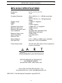
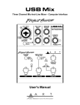
2
ART MPA Gold™ Microphone Preamplifier
TABLE OF CONTENTS
Introduction ............................................................................................ 3
Introduction .......................................................................................... 3
Features ............................................................................................... 3
Front Panel Controls ...............................................................................4
Input Gain Control................................................................................ 4
Input Impedance Control ..................................................................... 5
Analog Output Control ......................................................................... 5
HPF Control ........................................................................................ 5
Gain Switch.......................................................................................... 5
Phantom Switch ...................................................................................6
Phase Switch ...................................................................................... 6
Plate Voltage Switch ............................................................................ 6
Meter Switch ........................................................................................ 7
Tube Warmth Meter ............................................................................. 7
Front Panel Connections.........................................................................8
Instrument Inputs ................................................................................. 8
Rear Panel Connections ......................................................................... 8
Balanced Inputs ................................................................................... 8
Balanced Outputs ............................................................................... 8
Signal Path ...............................................................................................9
Signal Path Flow Diagram ....................................................................9
Signal Path Flow .................................................................................10
Operating Instructions .........................................................................
Obtaining the best noise performance ...............................................
Adjusting the input impedance ...........................................................
Setting the tube plate voltage ............................................................
10
10
10
11
Warranty Information ........................................................................... 12
Service .................................................................................................. 12
Specifications ....................................................................................... 13
2
ART MPA Gold™ Microphone Preamplifier
3
MPA GOLD INTRODUCTION
The ART MPA Gold™ microphone preamplifier features a new low noise, high
performance preamplification circuitry designed for superior audio fidelity. Building upon
the quality and success of great sounding products like the Pro MPA, ART engineers
set out to develop the next generation of professional microphone preamplifier. The
MPA Gold is the culmination of years of research and development, and sets a new
standard for quality and value. Professional features and spectacular tone are what
make the MPA Gold a world-class microphone preamplifier.
MPA GOLD FEATURES:
•
•
•
•
•
•
•
•
•
•
•
•
•
Variable input impedance for flexible microphone voicing (150 Ohms to 2400 Ohms).
Selectable plate voltage
Large VU meters
Front accessible meter trim
Meter selectable between –10dB and +4dB ranges
Tube warmth LED meter
Improved discrete class A input microphone preamplifier
Lower noise at low gains
Lower THD
Wider frequency response
Front accessible Instrument Input Jack
Very high input impedance
Automatically switches to the instrument input when you plug in
The MPA Gold is an attractively styled processor, with a light gold colored front panel
and matching knobs. Its Switch caps are illuminated when activated.
3
ART MPA Gold™ Microphone Preamplifier
4
FRONT PANEL CONTROLS
Input Gain control
This control optimizes the input signal level before the tube gain is applied. Both
Microphone and Instrument input gains remain the same and are affected by this
adjustment. Input gain can be adjusted from 0dB (for line level signals) to 45dB of gain.
The analog meters are used to see the effects of the input gain setting.
Additional gain is available via the Gain switch (+20dB) and the Analog Output control
(+10dB) for a maximum of 75dB total.
The combination of these controls allows the user to adjust the signal level through the
tube section, providing more or less “tube” sound as needed. To obtain more “tube’
sound, increase input gain, use the +20dB Gain switch, “normal” plate voltage, and less
Analog output gain.
4
ART MPA Gold™ Microphone Preamplifier
5
Both the microphone and instrument inputs are optimized for their respective sources as
far as signal levels and noise performance. Running most of the gain on the input
generally provides the best performance of the MPA Gold. Refer to the section titled
“Obtaining the best noise performance with the MPA Gold” for more detailed
instructions on setting the Input Gain control for the best results.
Input Impedance control
This knob controls the Mic/line input amplifier impedance. This function allows variable
voicing of any microphone.
Refer to the application section titled “Adjusting the Input Impedance” for more
information on making the most of this function.
The ¼” instrument input is NOT affected by this control, and remains high (>1M Ohm)
impedance.
Analog Output control
The output signal level at the rear output jacks is adjusted by this control. It can provide
from +10dB of gain (fully clockwise) to completely muted. You can see the effects of this
adjustment reflected in the analog meters when the meter switch is set to “output”.
HPF control
The HPF is a single tuned High Pass Filter that is frequency tunable. The input signal
can be filtered to remove “pops” or other extraneous low frequency information. This
control moves the rolloff frequency from 10 Hz (fully CCW) to 200 Hz (fully CW). Since
it is single tuned, it preserves some low frequency content so its use is less obtrusive. It
is especially useful in close mic’d applications.
Gain switch
The Gain switch is used in conjunction with the input gain control to adjust signal levels
through the MPA Gold. When depressed, the tube circuit provides 20dB more gain in
the signal path. This also has the effect of driving the tube harder and making the tube
the dominant source of gain and overload character.
5
ART MPA Gold™ Microphone Preamplifier
6
Phantom switch
Phantom power on the microphone input is turned on and off with this switch.
Depressing the switch will power condenser microphones and other 48volt phantom
powered devices. Phantom power is supplied to pins 2 and 3 of the input jack.
NOTE:
1) Dynamic microphones are NOT affected by Phantom power, although it should be
turned off when using dynamic microphones or line level inputs.
2) Although the 48volt phantom power ramps up and down slowly it may still create a
pop. Mute the output of the MPA Gold when engaging or disengaging phantom power to
prevent damage to equipment following the MPA Gold.
Phase switch
The Phase switch can invert the phase of the audio signal path in either channel. The
Phase switch is located after the tube circuit in the signal path, so you can hear slight
differences between different phase selections in the “normal” plate voltage mode near
saturation. There are a number of reasons why adjusting the phase is needed these
include, wiring errors and inversions in some audio equipment. Some microphones
sound different depending on the phase chosen.
If two microphones are out of phase, they may cancel at various frequencies
(depending on the distance between them). If this happens, try changing the phase of
one of the microphones and see if there is an improvement.
Plate Voltage switch
This switch sets both the tube bias point and the plate voltage level the balanced
differential tube circuit runs at. The amount of headroom is adjusted by using the Gain
switch and the input Gain control. The MPA Gold takes about 10-30 seconds to
smoothly transition from one mode to the other. There is a slight increase in gain in the
“High” plate voltage mode.
6
ART MPA Gold™ Microphone Preamplifier
7
In the “normal” (OUT) position, the tube distortion gradually rises until it smoothly clips.
The tube is run almost completely open-loop in this mode, providing a musical tube
“crunch” when overdriven with a natural recovery from clipping. The tube section can be
more easily overdriven when the gain switch is in. This mode brings out the harmonics
in the input sources, particularly stringed instruments.
The tube circuit runs extremely clean in the “high” (IN) position of the plate voltage
switch. As signal levels rise distortion remains very low until within 6dB of clipping,
where the overload characteristics smoothly limit the signal swing. There is increased
bandwidth (>100KHz), and headroom in this mode as well.
Meter switch
The analog meters monitor the output signal at the output. The switch selects the
sensitivity of the meter.
0VU on the meter measures +4dBu at the output jacks in the “+4dB” position.
Depressing the switch changes 0VU on the meter to become –10dBu at the output
jacks.
Tube Warmth Meter
The LED meters monitor the operation of the tube section. The meter reads both the
average and peak level. Average levels are shown as a histogram. Peaks are held for
one second by a single LED. In “normal” plate voltage mode “0” on this meter indicated
less than 5dB of headroom, and a great deal of tube warmth. Monitor the average levels
to gauge the tube warmth, as most of the peak levels held are so short they contribute
little to the perceived warmth. In “high” plate voltage mode there is more tube circuit
headroom. “0” on the meter indicates less than 10dB of headroom.
Front Panel Connections
Instrument Inputs
The ¼” jacks on the front panel serve as an instrument input. The input impedance is
always >1M Ohm and the gain can be adjusted by the Input gain control. The maximum
input signal level is +17dBu (5Vrms) @ minimum input gain.
7
ART MPA Gold™ Microphone Preamplifier
8
When you plug into this jack it DISABLES the balanced input on the rear of the unit.
This feature allows you to keep the rear input patched in, and use the instrument input
to switch to a different source. The instrument input allows the MPA Gold to serve as a
great DI device as well.
Rear Panel Connections
Balanced Inputs
The MPA Gold’s XLR connectors follow the AES standard of Pin 1 = Ground, Pin 2 =
Hot (+), Pin 3 = Cold (-). The Balanced inputs have an input impedance that is variable
from 150 to 3K Ohms via the front panel control. The Maximum input level is +19dBu
balanced and +17dBu unbalanced.
Balanced Outputs
The MPA Gold‘s flexible active balanced outputs are available on both ¼” and cannon
connectors. They offer low impedance for driving long cable runs and are intelligent
enough to maintain the same output level whether it is balanced or unbalanced.The
MPA Gold’s XLR connectors follow the AES standard of Pin 1= Ground, Pin 2= Hot (+),
Pin 3= Cold (-). The balanced ¼” phone jacks are typical Tip = Hot (+), Ring = Cold (-),
Sleeve = Ground. Maximum output level is +26 balanced and +20 unbalanced.
8
ART MPA Gold™ Microphone Preamplifier
9
MPA GOLD SIGNAL FLOW
SIGNAL PATH FLOW
The signal path of the MPA Gold consists of a discrete class A microphone pre-amp
followed by a Hi Pass Filter, a balanced differential tube circuit with a 20dB Gain switch
and then the phase switch. The tube warmth meter monitors the tube circuit output. At
this point the signal passes to the analog output. The analog meters measure the output
level of the MPA GOLD.
9
ART MPA Gold™ Microphone Preamplifier
10
MPA GOLD OPERATING INSTRUCTIONS
Obtaining the best noise performance with the MPA GOLD
Start by turning down the Input Gain knob and centering the Analog Output knob. Use
the analog meter to view the operating level by depressing the switch under the center
of the analog meter. The meter will now indicate how much tube headroom there is. Set
the +20dB switch to the out position.
Increase the Input Level knob until the meter reads above –15dB. If you have turned the
input knob fully clockwise and the indicated level is still below –15dB on the meter,
center the input knob and depress the Gain switch. Increase the Input Gain until there is
sufficient level.
This procedure optimizes the gain elements to provide the widest dynamic range
possible.
Adjusting the Input Impedance
The same microphone can sound different on various pre-amps. One reason is that
every pre-amp presents a different load on its input, some even change as gain is
changed! Our third generation discrete front end was designed to be absolutely
transparent. Every nuance of the microphone is maintained providing detail masked by
inferior pre-amps. The Input Impedance control is one key element in providing new
versatility in voicing microphones.
NOTE: the Input impedance control only affects the cannon connector inputs. The ¼”
instrument input on the front panel is NOT affected by this control in any way. The
instrument input impedance is ALWAYS >1M Ohm.
Dynamic microphones are affected as much as phantom powered units.
We provide a continuously variable impedance control to allow you to fine-tune the
voicing, finding the perfect interaction between microphone and pre-amp.
10
ART MPA Gold™ Microphone Preamplifier
11
Start by setting the centering the Input Impedance knob. This provides a 600-Ohm load.
Lower impedance loads will reject more noise picked up by cabling, and dampen
microphone resonance. Higher impedance settings provide a more “open” sound. Lower
impedances tend to focus the sound more.
Setting the Tube Plate Voltage
The MPA Gold allows the user to select between one of two vastly different tube bias
settings and power supply levels. The transition between either setting is smooth and
quiet and the gain variation is minimal.
NOTE: It takes 15-30 seconds for the tube circuit to fully transition between either
mode. During this time, the unit passes a signal and the only noticeable change is a
slight increase in level in the “HIGH” setting.
The “Warm” setting produces a smooth transition from very clean low levels up to a
“round” saturated clipping on peaks. This setting is reminiscent of old tube gear, and is
intended to get the most tube-like sound out of the unit. Common uses include tracking
with instruments.
The “High” setting of the plate voltage switch has increased bandwidth and headroom,
very low distortion and runs extremely clean until it reaches a point of saturated clipping.
The clipping is well controlled and still sounds natural. This setting is incredible on
vocals.
11
ART MPA Gold™ Microphone Preamplifier
12
WARRANTY INFORMATION
Limited Warranty
Applied Research and Technology will provide warranty and service for this unit
in accordance with the following warrants:
Applied Research and Technology (A R T) warrants to the original purchaser that
this product and the components thereof will be free from defects in workmanship
and materials for a period of five years from the date of purchase. Applied
Research and Technology will, without charge, repair or replace, at its option,
defective product or component parts upon prepaid delivery to the factory service
department or authorized service center, accompanied by proof of purchase date
in the form of a valid sales receipt.
Exclusions
This warranty does not apply in the event of misuse or abuse of the product or as
a result of unauthorized alterations or repairs. This warranty is void if the serial
number is altered, defaced, or removed.
A R T reserves the right to make changes in design or make additions to or
improvements upon this product without any obligation to install the same on
products previously manufactured.
A R T shall not be liable for any consequential damages, including without
limitation damages resulting from loss of use. Some states do not allow
limitations of incidental or consequential damages, so the above limitation or
exclusion may not apply to you. This warranty gives you specific rights and you
may have other rights, which vary from state to state.
For units purchased outside the United States, an authorized distributor of
Applied Research and Technology will provide service.
12
ART MPA Gold™ Microphone Preamplifier
13
SERVICE
The following information is provided in the unlikely event that your unit requires
service.
1) Be sure that the unit is the cause of the problem. Check to make sure the unit
has power supplied, all cables are connected correctly, and the cables
themselves are in working condition.
2) If you find the unit to be at fault, write down a complete description of the
problem, including how and when the problem occurs. Please write down a
description of your complete setup before calling Customer Service.
3) Call the factory (585-436-2720) for a Return Authorization (RA) number.
4) Pack the unit in its original carton or a reasonable substitute. The packing box
is not recommended as a shipping carton. Put the packaged unit in another box
for shipping. Print the RA number clearly on the outside of the shipping box. Print
your return shipping address on the outside of the box.
5) Include with your unit: a return shipping address (we cannot ship to a P.O.
Box), a copy of your purchase receipt, a daytime phone number, and a
description of the problem.
6) Ship only your unit and its power supply (keep your manual!) to:
APPLIED RESEARCH AND TECHNOLOGY
215 TREMONT STREET
ROCHESTER, NEW YORK 14608
ATTN: REPAIR DEPARTMENT
RA# ____________________
7) Contact our Customer Service department at (585) 436-2720 for your Return
Authorization number or questions regarding technical assistance or repairs.
Customer Service hours are 9:00 AM to 5:00 PM Eastern Time, Monday through
Friday.
13
ART MPA Gold™ Microphone Preamplifier
14
MPA GOLD SPECIFICATIONS
Dimensions:
Weight:
6.5” D x 19.0” W x 3.5” H
12 Lb.
Frequency Response
Maximum Output Level
Output Impedance:
Maximum Gain
15Hz to 48 kHz (+0, -1dB) @ normal plate
voltage
15Hz to 120 kHz (+0, -1dB) @ high plate
voltage
>110dB (“A” weighted)
>90dB
<0.005% (typical)
-133dBu (XLR, “A” weighted)
+20dBu (cannon)
+17dBu
150-3000 Ohms adjustable (XLR)
>800K Ohms (Instrument)
+27dBu (XLR)
< 47 Ohms (XLR)
75dB
Meter Calibration
High Pass Filter
0 VU = +4dBu or –10dBu output, selectable
single pole, 10-200 Hz adjustable
Power Requirements:
100-125 VAC, 25W. Export Units configured for
country of destination
Dynamic range:
CMRR:
THD:
Equivalent Input Noise:
Maximum Input Level:
Maximum Instrument Input:
Input Impedance
APPLIED RESEARCH & TECHNOLOGY
215 TREMONT STREET
ROCHESTER, NEW YORK 14608 USA
Phone (585) 436-2720 (585) 436-3942 – Fax
www.artproaudio.com e-mail: [email protected]
MPA GOLD –Tube Microphone Preamplifier mpag-5004-100
14