1
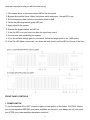
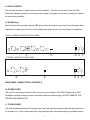
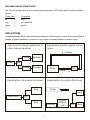
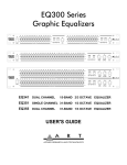
442 EQ
DUAL CHANNEL 15 BAND 2/3 OCTAVE GRAPHIC EQUALIZER
452 EQ
SINGLE CHANNEL 31 BAND 1/3 OCTAVE GRAPHIC EQUALIZER
USER’S GUIDE
EQUALIZER OVERVIEW – FEATURES AND GENERAL INFORMATION:
MODEL 442 TWO CHANNEL 15 BAND 2/3 OCTAVE PRECISION GRAPHIC EQUALIZER
The Model 442 features constant Q circuitry with a 3% center frequency accuracy. Special features
include 60MM full range precision Sliders, LED metering, selectable range 6dB or 12dB, active
balanced and unbalanced input/output connectors, RFI filters, variable input level control, passive
bypass switch, clip level indicators, ground lift switch, and selectable line voltage switch.
MODEL 452 SINGLE CHANNEL 31 BAND 1/3 OCTAVE PRECISION GRAPHIC EQUALIZER
The Model 452 features constant Q circuitry with a 3% center frequency accuracy. Special features
include 60MM full range precision Sliders, LED metering, selectable range 6dB or 12dB, active
balanced and unbalanced input/output connectors, and RFI filters. The unit also has variable Hi Pass
(low cut) and Low Pass (high cut) filters, variable input level control, passive bypass switch, clip level
indicator, a ground lift switch, and selectable line voltage switch.
INSTALLATION
The Model 442 and 452 Equalizers are designed for mounting in a standard 19” equipment rack or
one of the many rack type portable cases available on the market. The vertical measurements are 3.2
inches. Both models are 8.5 inches in depth.
POWER CONNECTORS
The Model 442 and 452 Equalizers have internal power supplies and are designed for operation from
120-240 volt, 50-60Hz mains supply. Power consumption is 12 watts. In new installations and portable sound systems, or any situation in which the mains power is in question, it is wise to confirm the
voltage and select the appropriate line voltage switch BEFORE connecting the equalizer to power
sources.
INPUT/OUTPUT CONNECTIONS
The Model 442 and 452 Equalizers have three paralleled input and output connectors. XLR and 1/4”
TRS are actively balanced with pin 2 or the tip being Hi (Hot), Pin 3 or the ring being Lo, and Pin 1 or
sleeve being ground. Unbalanced operation requires using the RCA phono connector or use Pin 2 of
the XLR or tip 1/4” TRS as ground.
2
Balanced output requires using Pin 2 of the XLR or the tip of the 1/4” TRS as output Hi (+) and using
pin 3 of the XLR or the ring of the 1/4” TRS as Lo (-). It does not require pin 1 or signal ground. The
signal exists differentially between the two balanced leads. Ground is used only for shielding to
prevent potential hum. Paralleling inputs and outputs may be accomplished by using any of the three
connectors. Note: 1/4” TRS are normally used.
SIGNAL LEVELS
Signal levels from -10 dBu to +4 dBu are considered normal and 20dB of headroom exists above
these levels. Do not connect microphones directly to the equalizer. Microphones require a preamp.
CHASSIS GROUNDING
The Model 442 and 452 Equalizers are equipped with a rear panel Ground Lift switch. After setting up
your system, if the system exhibits excessive hum or buzzing, the problem may be a ground incompatibility between your equalizer and other equipment in the same system. There are several combinations that can be attempted. NOTE: ALWAYS TURN YOUR AMPLIFIERS DOWN BEFORE
CHANGING GROUNDS. Try different combinations of lifting grounds on units that are supplied with
ground lift switches or make sure all chassis are connected to earth ground, either through the AC
Power cord ground or by the front panel rack mount screws.
OPERATING INSTRUCTIONS
Before starting to equalize your sound system there is some information you should know and procedures you should follow. Your equalizer is equipped with a bypass switch. The bypass switch, when
activated, lights the LED and cancels all equalization settings while allowing signal to flow through the
unit at unity gain.
Also included is a range selection switch with LED indicators, 6dB =green, 12dB= yellow. In addition
to the range selection switch there is a level control potentiometer. The level control operates between off and +6dB. Note: If there is too much gain your equalizer has a red LED Clip indicator. The
Clip LED illuminates when signals reach 5dB prior to clipping. If this situation occurs and the overload
LED flashes occasionally, this is okay. However, if the overload LED is steadily on, you must readjust
the level control.
3
Here are some tips to help you with the initial set up:
1. Set channel levels to the center detent 0dB on the front panel.
2. Bypass the equalizer (Note: Select the bypass switch and press - the red LED is on.)
3. Set the frequency slide controls to the center detent or 0dB.
4. Select the 6dB range switch (green LED on).
5. Apply signal to the system.
6. Release the bypass switch, red LED off.
7. If the Clip LED is on you must turn down the input level control.
8.You may now start equalizing your system.
9. If you do not have enough gain for your needs, switch the range switch to the 12dB setting.
10. If the Clip LED lights continuously, turn down the level control until the LED is off most of the time.
FRONT PANEL CONTROLS
1. POWER SWITCH
To turn the equalizer ON or OFF, press the upper or lower portion of this button. CAUTION: Always
turn on your equalizer BEFORE your power amplifiers are turned on, and always turn off your equalizer AFTER your power amplifiers have been turned off.
4
2. FILTER LEVEL CONTROLS
Each of these sliders controls the output level of each of the 31 (or 15) bandpass filters. The center
detent position is grounded to assure flat response.
3. FILTER RANGE SWITCH & INDICATORS
The gain range of the filter sliders is switchable (as a group) from +/- 6dB to + /-12dB for maximum
boost/cut capability. At 6dB the green LED will illuminate and at 12dB the yellow LED will illuminate.
4. BYPASS SWITCH & INDICATOR
When the red LED is illuminated, this indicates that the unit or channel is in the bypass mode. Signal
is routed directly from the input to the output without passing through any circuit (often referred to as
”hard-wire bypass”). Use this switch to compare equalized and unequalized material, or to bypass the
EQ section in the event of power loss or unit failure.
5. OVERLOAD INDICATOR
This red LED illuminates if any section of the equalizer is within 5dB of clipping. Occasional flickering
of this LED is acceptable, but if it remains on more than intermittently you should turn down either the
equalizer’s level controls or reduce the output level of the preceding component to avoid audible
distortion.
6. HI PASS FILTER (LOW-CUT FREQUENCY CONTROL)
To cut down on unwanted low frequency signals, this control determines the roll-off frequency of the
High-Pass Filter (HPF). The roll-off frequency can be adjusted from 10Hz to 250Hz by turning this
knob. Because of its high roll-off slope, the HPF can be efficiently used to cut down the ”HUM” noise
from preceding instruments, or to reduce low frequency resonances, when speakers are installed in
an enclosed acoustic environment.
7. LOW PASS FILTER (HIGH-CUT FREQUENCY CONTROL)
To cut down on unwanted high frequency signals, this control determines the roll-off frequency of the
Low-Pass Filter (LPF). The roll-off frequency can be adjusted from 3kHz to 40kHz by turning the
knob. Because of its high roll-off slope, the LPF can be effectively used to cut down the high frequency noise from preceding instruments, or roll-off excessive high frequency sounds to obtain a
more natural sound in acoustic situations.
5
8. LEVEL CONTROL
This controls the level of signal coming into the equalizer. Turn this control down if the Clip LED
illuminates steadily (meaning too strong an input signal). Unity gain can be set by turning this knob to
its center detent position.
9. LED Metering
Each channel of the equalizer has an LED array meter, showing its output level. Use the meter when
adjusting the output level Control to aid in sending the proper level to your next piece of equipment.
DUAL 15 BAND GRAPHIC EQUALIZER
14
13
12
11
10
31 BAND GRAPHIC EQUALIZER
14
13
12
11
10
REAR PANEL CONNECTORS & CONTROLS
10. POWER CORD
This cord is used connect the AC power source to your equalizer. CAUTION: Equipment for USA
installation includes a captive power cord with a three-pin polarized plug. DO NOT REMOVE THE
CENTER GROUNDING PIN.
11. FUSE HOLDER
This fuse holder contains the AC primary fuse. This fuse should be replaced with the same type fuse
if it is blown out. If they continuously blow, stop replacing fuse and refer servicing to qualified person6
nel. CAUTION: After checking the AC supply voltage, be sure that the correct fuse is in the fuse
holder; 0.6Amp for 100-103VAC, as well for 220-240VAC.
12. AC VOLTAGE SELECTOR
Set this slide switch to match your line voltage supply. CAUTION: For new installations and portable
sound systems, or any situation in which the mains power is suspect, it is wise to confirm appropriate
voltage and line polarity BEFORE connecting the instrument to power source.
13. GROUND LIFT SWITCH
This switch is used to disconnect the signal ground from the mains and chassis earth ground. You
may set the switch to the LIFT position if ”HUM”, caused by a ground loop, can be heard at the
speakers.
14. INPUT/OUTPUT CONNECTORS
1/4 TRS
The TRS (Tip Ring Sleeve) connector is balanced and wired as tip = Hi (+), Ring = Lo (-), and Sleeve
= Ground.
CAUTION: Only one of these sockets can be chosen for audio connection at the same time.
XLR
The XLR input connector is balanced and wired as Pin 2=Hi (+), Pin 3=Lo (-), and Pin 1=Ground.
CAUTION: Only one of these sockets can be chosen for audio connection at the same time.
RCA PHONO
The RCA Phono input is unbalanced at the tip = Hi (+) and the Sleeve = Ground.
CAUTION: Only one of these sockets can be chosen for audio connection at the same time.
FOR BALANCED CONNECTIONS
Wire the connectors as follows:
Phone Jack:
Connection:
tip
=
high
ring
=
low
sleeve
=
ground
7
FOR UNBALANCED CONNECTIONS
Use 1/4 inch tip-ring-sleeve or mono phone plug connectors or RCA phone jack connectors wired as
follows:
Phone Jack:
Connection:
tip
=
high
ring
=
no connection
sleeve
=
ground
APPLICATIONS
Graphic equalizers may be used wherever modification of the frequency contour of a sound system is
needed. A graphic equalizer is a solution to any number of sound problems or creative urges.
Typical reinforcement application of
a two channel equalizer
Equalizaton of audio signals from a
mixer
Return
Mixer
P Amp
Speaker
P Amp
Speaker
EQ
Mixer
EQ
Send
Equalization of a musical instrument
Equalization of a guitar effects loop
Guitar
Amp
Amp
Instrument
EQ
Amp
PreAmp
8
Stereo
Effects
loop
EQ
Amp
WARRANTY INFORMATION
Limited Warranty
Applied Research and Technology will provide warranty and service for this unit in accordance
with the following warrants:
Applied Research and Technology (A R T) warrants to the original purchaser that this product
and the components thereof will be free from defects in workmanship and materials for a period of three years from the date of purchase. Applied Research and Technology will, without
charge, repair or replace, at its option, defective product or component parts upon prepaid delivery to the factory service department or authorized service center, accompanied by proof of
purchase date in the form of a valid sales receipt.
Exclusions
This warranty does not apply in the event of misuse or abuse of the product or as a result of
unauthorized alterations or repairs. This warranty is void if the serial number is altered, defaced, or removed.
A R T reserves the right to make changes in design or make additions to or improvements
upon this product without any obligation to install the same on products previously manufactured.
A R T shall not be liable for any consequential damages, including without limitation damages
resulting from loss of use. Some states do not allow limitations of incidental or consequential
damages, so the above limitation or exclusion may not apply to you. This warranty gives you
specific rights and you may have other rights, which vary from state to state.
For units purchased outside the United States, an authorized distributor of Applied Research
and Technology will provide service.
9
SERVICE
The following information is provided in the unlikely event that your unit requires service.
1) Be sure that the unit is the cause of the problem. Check to make sure the unit has power
supplied, all cables are connected correctly, and the cables themselves are in working condition.
2) If you find the unit to be at fault, write down a complete description of the problem, including
how and when the problem occurs. Please write down a description of your complete setup before calling Customer Service.
3) Call the factory for a Return Authorization (RA) number.
4) Pack the unit in its original carton or a reasonable substitute. The packing box is not recommended as a shipping carton. Put the packaged unit in another box for shipping. Print the
RA number clearly on the outside of the shipping box. Print your return shipping address on
the outside of the box.
5) Include with your unit: a return shipping address (we cannot ship to a P.O. Box), a copy of
your purchase receipt, a daytime phone number, and a description of the problem.
6) Ship only your unit and its power supply (keep your manual!) to:
APPLIED RESEARCH AND TECHNOLOGY
215 TREMONT STREET
ROCHESTER, NEW YORK 14608
ATTN: REPAIR DEPARTMENT
RA# ____________________
7) Contact our Customer Service department at (585) 436-2720 for your Return Authorization
number or questions regarding technical assistance or repairs. Customer Service hours are
9:00 AM to 5:30 PM Eastern Time, Monday through Friday.
10
SPECIFICATIONS
EQUALIZER
Bands
Type
Accuracy
Travel
Range
INPUTS
Type
Connectors
Impedance
Maximum Level
OUTPUTS
Type
Connectors
Impedance
Maximum Level
OVERALL GAIN RANGE
RFI filters
Passive Bypass Switches
Overload LED Threshold
High Pass Filter
Low Pass Filter
Frequency Response
THD + Noise
IM Distortion (SMPTE)
Signal to Noise Ratio
Channel Separation
Common Mode Rejection
1*31, 1/3 Octave ISO Spacing From 20Hz to 20kHz. (model 452)
2*15, 2/3 Octave ISO Spacing From 25Hz to 16kHz. (model 442)
Constant Q
3% Center Frequency
60mm (Oil Dampened, Positive Center Detent) for 1*31, 2*15
+/- 6dB or +/- 12dB (Selectable)
Active Balanced/Unbalanced
3-Pin, 1/4” TRS (Balanced). RCA. (Unbalanced)
20k. Ohms Balanced; 15K Ohms Unbalanced
+22dBm (Level Control at Center)
Active Balanced/Unbalanced
3-Pin, 1/4” TRS (Balanced). RCA (Unbalanced)
Typical <150 Ohms
+22dBm (2k Ohms)
+18dBm (600 Ohms)
Off to +6dB (Unbalanced out)
Sliders Centered
Off to +12dB (Balanced out)
Sliders Centered
Yes
Yes
5 dB (Below Clipping)
10-250Hz, 12dB/Oct
3k-40kHz, 12dB/Oct
20-20kHz, +0.5dB
.01% (20Hz-40kHz+10dBu)
0.005%
-94dB(20kHz Noise Bandwidth)
>50dB
50:1
LINE VOLTAGE
95-130VAC, 50/60Hz.
190-250VAC, 50Hz.
INPUT AC POWER
12W
Construction: all Steel
SIZE
3.5” H *19” W *8.5” D (2U)
(8.9cm * 48.3cm * 21.6cm)
WEIGHT
9Ibs.(4.1kg).
11
APPLIED RESEARCH & TECHNOLOGY
215 TREMONT STREET
ROCHESTER, NEW YORK 14608 USA
(585) 436-2720 – Voice
(585) 436-3942 – Fax
http://www.artproaudio.com
E-mail: [email protected]
442 EQ
DUAL CHANNEL 15 BAND 2/3 OCTAVE GRAPHIC EQUALIZER
452 EQ
SINGLE CHANNEL 31 BAND 1/3 OCTAVE GRAPHIC EQUALIZER
442-5004-100
12