1
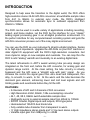
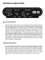
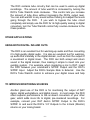
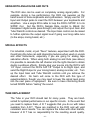
The ART
DI/O
TABLE OF CONTENTS
Introduction ......................................................................................... 2
Installation ...........................................................................................
AC Power Hookup .............................................................................
Audio Connections ............................................................................
Safety Precautions ............................................................................
3
3
3
3
Controls and Indicators ....................................................................... 4
Input Gain Control ............................................................................. 4
Sample Rate Switch .......................................................................... 4
Sample Rate LED Indicators ............................................................. 5
Signal Level LED Indicators ............................................................... 5
Tube Warmth Control ........................................................................ 6
Power LED Indicator ......................................................................... 6
Connections ........................................................................................
¼” Input Jacks....................................................................................
¼” Output Jacks ................................................................................
S/PDIF Output Jack ...........................................................................
S/PDIF Input Jack .............................................................................
Power Jack .......................................................................................
7
8
8
8
8
9
Operation ........................................................................................... 10
Warranty Information ........................................................................ 14
Service ............................................................................................... 15
DI/O Specifications ............................................................................ 16
-1-
INTRODUCTION
Designed to help ease the
high-resolution stereo 24-bit
from 44.1 to 96kHz. In
synchronization allows for
22kHz to 100kHz.
transition to the digital world, the DI/O offers
A/D-D/A conversion at switchable sample rates
external sync mode, the DI/O’s intelligent
automatic sync to outboard equipment from
The DI/O can be used in a wide variety of applications including recording,
project, and home studios. Let the DI/O be the interface for your “classic”
analog signal processing gear in an all-digital production environment. It’s
the perfect interface for any computer-based recording system and gets the
A/D-D/A conversion process out of the noisy digital environment.
You can use the DI/O as your instrument’s direct-to-digital interface, thanks
to its high input impedance. Upgrade the A/D-D/As on your DAT machine or
older digital I/O equipment with the DI/O’s high-resolution converters. Get
more dynamic range on new samples and overdubs. You can loop thru the
DI/O to add “analog” warmth and musicality to an existing digital track.
The latest refinements in ART’s award winning tube pre-amp design are
integrated on the front end, before the A/D converter, for analog gain and
dynamic range control. At the clean setting, the tube circuitry is virtually
bypassed and the A/D sees a “straight wire with gain” signal. As you
increase the control the signal goes from ultra clean and transparent, thru
silky, to smooth, to warm, to fat. At the warm end the tube becomes the
dominant gain element, enhancing lower and mid level signals and soft
limiting peaks and overshoots before they hit the A/D.
FEATURES:
• 2 channels of A/D and 2 channels of D/A conversion
• High Resolution 24-bit, 96kHz, 128x oversampling converter
• 44.1, 48, 88.2, 96kHz switch-selectable sample rates
• Intelligently syncs to external sample rates from 22kHz to 100kHz
• S/PDIF Coaxial, Digital inputs and outputs, RCA type jacks
• Hand-selected 12AX7A dual triode tube
• Fully variable tube character from transparent to warm
• ¼” High impedance stereo inputs and ¼” line level stereo outputs
• Variable input gain from 0dB(unity) to +20dB
-2-
INSTALLATION
The DI/O may be used in a wide variety of applications and
environments. Self-contained in an all-steel enclosure, the DI/O is
designed for continuous professional use. Because the unit is compact
and lightweight, mounting location is not critical. However, for greater
reliability we recommend that you not place the DI/O on top of power
amps or other sources of heat. The tube circuitry needs about a minute
to “warm up” from a cold power up.
AC POWER HOOKUP
The DI/O has an external power supply designed to operate at 115
VAC @ 50 to 60 Hz. Units manufactured for use outside the United
States of America have been modified to comply with the required
electrical specifications. Only use the adapter that came with the
DI/O. If the adapter becomes lost or damaged; contact ART Customer
Service for replacement. If you need to purchase one locally, just make
sure that you specify 9 Volt AC output (not DC), at 800 ma.
AUDIO CONNECTIONS
Audio connections to and from the DI/O are unbalanced ¼” (Tip = Hot
(+), Sleeve = Ground). We recommend that you turn down the INPUT
GAIN control whenever changing connections to the inputs.
SAFETY PRECAUTIONS
Warning: To avoid the risk of shock or fire, do not expose this unit to
moisture. Refer all servicing to qualified personnel. Do not remove the
metal cover; there are no user-serviceable parts inside. You should
only use the power adapter that came with this unit or one obtained
from ART’s Customer Service Department.
-3-
CONTROLS & INDICATORS
INPUT GAIN CONTROL
The Input Gain control allows you to add gain to the input signal before
the tube and A/D converter. Turn the control clockwise to increase gain
and counterclockwise to decrease gain. At the fully counterclockwise
position (0dB), incoming signals are passed at unity gain to the A/D
converter. At this setting the inputs can handle “hot” signals, up to
+20dBu, before clipping the A/D. When the Input Gain control is at the
fully clockwise position (+20dB), the incoming signal is boosted in level
before the A/D. This allows you to increase low level signal sources by
up to 20dB, to maximize the input dynamic range of the A/D. In normal
operation you would increase the Input Gain control until the red “0dB”
LED just lights on signal peaks.
SAMPLE RATE SWITCH
Use the Sample Rate Switch to select the desired sample rate. Each
time you press the switch, it increments through the available choices
while the LEDs beside it show the current state. The DI/O remembers
the sample rate setting and powers up at the same sample rate that it
was in before power was removed. This allows you to, in many
applications, set the sample rate for your system once and leave it.
-4-
SAMPLE RATE LED INDICATORS
The Sample Rate LED Indicators show the current sample rate that the
DI/O’s A/D and D/A are operating at. When set to one of the internally
generated sample rates (44.1, 48, 88.2, or 96kHz), the DI/O provides
the Master clock source from its internal crystal clock.
When set to the External Sync position, the DI/O will use the S/PDIF In
jack as the source of its Master clock. It will synchronize to, and track,
sample rates from 22kHz to 100kHz. The green (Ext.) LED indicator
will light solid as long as the source has valid audio sync. It will flash if
the data on the S/PDIF input jack does not contain valid audio data.
When this occurs the D/A will mute its audio outputs to prevent
unwanted noise. The A/D will still digitize audio and track the external
Master clock.
SIGNAL LEVEL LED INDICATORS
The three Signal Level LED Indicators are designed to help set levels
before the A/D, to maximize your dynamic range.
The green (-20dB) LED comes on when the signal at the A/D is 20dB
below full-scale digital clipping on signal peaks. It just starts to come on
when the average signal is around 30dB below clipping. You should
increase your input signal level, or the DI/O’s Input Gain until this light
is on solid whenever there is signal for best performance.
The red (0dB) LED comes on when the signal at the A/D is 3dB away
from full-scale clipping. With most audio material, you would increase
the input signal or Input Gain until this light just starts to come on
during signal peaks.
The yellow (Warm) LED comes on whenever the tube is adding
warmth or character to the signal. This is a function of both the input
signal level and the Tube Warmth control.
-5-
TUBE WARMTH CONTROL
This control allows you to vary the tube circuits warmth contribution to
the audio signal chain. At the Clean end, there is essentially no tube
processing and the yellow Warm LED should not light.
As you turn up the control, the drive to the tube is increased while its
output is adjusted, to maintain a fairly constant output signal to the
A/D. At higher signal levels you will see the yellow (Warm) LED start
to come on, indicating that the tube circuit is doing some of the
processing. The audible effect is subtle at lower settings.
At the full Warm position, you will see the Warm LED on more of the
time, even at lower signal levels. Audibly, at this setting, the tube adds
low-order harmonics that tend to musically “thicken” the signal. Signal
peaks are also softened, rather than hard-clipped. Both of these effects
are what give the DI/O that “Analog Tape Saturation” sound at higher
levels with higher settings of the Warmth control.
POWER LED INDICATOR
The green Power LED lights solid to indicate that the DI/O is receiving
adequate power from its external power source. If it ever flickers, check
the connections, power adapter, or line voltage.
-6-
CONNECTIONS
variety of equipment. All inputs and outputs are located on the rear panel.
Standard ¼” audio inputs and outputs make patching simple.
-7-
¼” INPUT JACKS
The ¼” Input jacks are for instrument and line level signals. They have
a high input impedance to minimize any loading effects on instrument
pickups. They can also handle up to +20 dBu signals for line level
signal sources.
If nothing is plugged into the Input jacks, they automatically switch to
get their signal from the ¼” Output jacks. This allows you to loop the
digital signal thru the DI/O. In this configuration you only need S/PDIF
in and out connections.
¼” OUTPUT JACKS
The ¼” Output jacks have a low output impedance to drive a wide
variety of loads. They deliver a +20dBu signal level when the D/A is at
digital full scale. The output level at the jacks is solely a function of the
digital signal.
S/PDIF OUTPUT JACK
The digital output jack on the DI/O is an RCA type that outputs S/PDIF
stereo signals over coaxial shielded cable. The data format is S/PDIF
stereo 24bit data at up to 100kHz.
Due to this wide bandwidth, we recommend that you use high quality,
low loss, fully-shielded cabling for both of the S/PDIF connections.
S/PDIF INPUT JACK
The digital input jack on the DI/O is an RCA type that receives S/PDIF
stereo signals over coaxial shielded cable. The data format is S/PDIF
stereo 24bit data at up to 100kHz. This jack also serves as the Master
clock input when using the DI/O in External Sync mode.
-8-
POWER JACK
An external 9 Volt AC adapter powers the DI/O. Plug the adapter into
the PWR jack and then into a power outlet. Only use the adapter that
comes with the DI/O. If the adapter ever becomes damaged,
immediately discontinue use. They can be purchased locally or directly
from ART. Just make sure that you specify 9 Volt AC output (not DC),
at 800 ma.
Fill in the following information for your reference:
Date of purchase
___________________
Purchased from
___________________
SERIAL NUMBER ___________________
-9-
OPERATION
The main function of the DI/O is to provide a high-quality alternative to
the digital audio converters of your computer’s soundcard. Simply plug
the analog output from your instrument, mixer, or preamp into the
DI/O’s 1/4” Inputs and connect the DI/O’s S/PDIF Output to your
soundcard. Next, decide whether your DI/O or soundcard will provide
the digital clock source. Only one device, called the Master, can
provide the digital clock; this ensures that all other devices synchronize
themselves to just one source and correctly interpret the transmitted
digital information. Devices other than the Master must be put into
“External” clock mode to properly work together. Note: Due to the
DI/O’s high quality converters, we recommend that when possible, you
use the DI/O as the Master clock.
To make the DI/O the Master, first set up your soundcard to receive an
external clock source.
(Consult your soundcard’s manual for
information on how to do this.) Next, use the DI/O’s Sample Rate
switch to select the desired sample rate. For example, to select a
sample rate of 96kHz, repeatedly press the DI/O’s Sample Rate switch
until both the top (48/96) and middle (x2) lights are lit. The graphic on
top of the DI/O is provided to assist you with the different
configurations.
If instead you wish to use your soundcard as the Master clock source,
put the DI/O into External Sync mode by pressing the Sample Rate
switch until only the bottom (Ext.) light is lit. Select the desired sample
rate on your computer. (Consult your soundcard’s manual for
information on how to do this.)
Once the clock source and sample rate have been set, use the DI/O’s
Input Gain control to optimize the recording level. Generally, you
should watch your software’s Input Meters and adjust the DI/O’s Input
Gain control to a level just below clipping. (Again, check your
soundcard’s or software’s manual for information on setting optimal
levels.)
- 10 -
The DI/O contains tube circuitry that can be used to warm-up digital
recordings. The amount of tube warmth is increased by turning the
DI/O’s Tube Warmth knob clockwise. This control lets you increase
the amount of tube drive without increasing the DI/O’s output level.
You can add warmth to any sound without having to readjust the levels
going through the DI/O. If you wish to bypass the tube circuit
completely and simply use the DI/O for its high-quality analog to digital
converters, turn the Tube Warmth control fully counter-clockwise to the
Clean position.
OTHER APPLICATIONS:
USING BOTH DIGITAL INS AND OUTS
The DI/O is an excellent tool for warming-up audio and then converting
it to high-quality digital audio. It is also an excellent tool for warmingup audio that’s already in the digital domain, such as from the output of
a soundcard or digital mixer. The DI/O can both accept and return
sound in the digital domain, thus making it simple to insert into your
existing system. For example, when mastering a mix to DAT, insert
the DI/O between your soundcard’s S/PDIF Output and the DAT’s
S/PDIF Input. Adjust the DI/O’s Sample Rate to External. Use the
DI/O’s Tube Warmth control to enhance your digital mixes and help
TO IMPROVE MONITORING SOURCES
Another great use of the DI/O is for monitoring the output of DAT
decks, digital workstations, and digital mixers. In most cases, the DI/O
offers superior performance to the on-board converters of your other
gear, which adds more life to digital, pre-mastered recordings. For
example, connect your DAT deck’s S/PDIF Output to the DI/O’s
S/PDIF In and send the DI/O’s 1/4” Outputs to the 2-track (Monitor)
returns on your mixing board.
- 11 -
USING BOTH ANALOG INS AND OUTS
The DI/O also can be used on completely analog signal paths. For
example, during a live performance, the DI/O can sweeten up the
harsh sound of some keyboards and synthesizers. Simply use the 1/4”
Input and Output jacks to insert the DI/O between your keyboards and
amplifiers. Use a single RCA cable to loop the DI/O’s S/PDIF In to its
S/PDIF Out. Set the DI/O’s Sample Rate control to 96kHz (for
transparent digital audio pass-through) and adjust the Input Gain and
Tube Warmth controls as desired. The Input Gain control can be raised
to further optimize the output signal level if going over long cable runs
(to the amps, mixing board, etc.).
SPECIAL EFFECTS
For industrial, metal, or just “flavor” textures, experiment with the DI/O.
Overdriving the tube can add interesting textures when used on vocals
and other instruments, especially if you are going for analog tape
saturation effects. When using both analog Ins and Outs (see above)
it is possible to cascade the left channel into the right channel to obtain
doubly overdriven effects. Simply plug your source into the DI/O’s Left
1/4” Input, connect the DI/O’s Left 1/4” Output to its Right Input, and
send the Right Output to your mixing board, analog recorder, etc. Turn
up the Input Gain and Tube Warmth controls until you achieve the
desired effect. No harm will come to the DI/O with this type of
experimentation, though you may need to lower the signal level going
into the next piece of equipment. Be sure to have monitoring levels
turned DOWN before “testing” the sound.
TUBE REPLACEMENT
The Tube in your DI/O should last for many years. They are handsorted for optimal performance in our specific circuits. In the event that
you need to replace them, A R T suggests that you do so with tubes
available from A R T. These are matched to the DI/O and will yield
consistent sonic results. You can replace the tubes with other brands,
however A R T has no responsibility for the resulting sound quality.
- 12 -
They may sound better, they may sound worse. The choice is yours.
Please realize that unauthorized alterations to the DI/O will result in
voiding the warranty.
For more application ideas, information, and suggestions on complementary
equipment that can be used with the DI/O, visit our website at:
http://www.artproaudio.com
- 13 -
WARRANTY INFORMATION
Limited Warranty
Applied Research and Technology will provide warranty and service for this
unit in accordance with the following warrants:
Applied Research and Technology, (A R T) warrants to the original
purchaser that this product and the components thereof will be free from
defects in workmanship and materials for a period of three years from the
date of purchase. Applied Research and Technology will, without charge,
repair or replace, at its option, defective product or component parts upon
prepaid delivery to the factory service department or authorized service
center, accompanied by proof of purchase date in the form of a valid sales
receipt.
Exclusions:
This warranty does not apply in the event of misuse or abuse of the product
or as a result of unauthorized alterations or repairs. This warranty is void if
the serial number is altered, defaced, or removed.
A R T reserves the right to make changes in design or make additions to or
improvements upon this product without any obligation to install the same
on products previously manufactured.
A R T shall not be liable for any consequential damages, including without
limitation damages resulting from loss of use. Some states do not allow
limitations of incidental or consequential damages, so the above limitation or
exclusion may not apply to you. This warranty gives you specific rights and
you may have other rights, which vary, from state to state.
For units purchased outside the United States, an authorized distributor of
Applied Research and Technology will provide service.
- 14 -
SERVICE
The following information is provided in the unlikely event that your unit
requires service.
1) Be sure that the unit is the cause of the problem. Check to make sure the
unit has power supplied, all cables are connected correctly, and the cables
themselves are in working condition.
2) If you find the unit to be at fault, write down a complete description of the
problem, including how and when the problem occurs. Please write down a
description of your complete setup before calling Customer Service.
3) Contact our Customer Service department at (716) 436-2720 for your
Return Authorization number or questions regarding technical assistance or
repairs. Customer Service hours are 9:00 AM to 5:30 PM Eastern Time,
Monday through Friday.
4) Pack the unit in its original carton or a reasonable substitute. The packing
box is not recommended as a shipping carton. Put the packaged unit in
another box for shipping. Print the RA number clearly on the outside of the
shipping box. Print your return shipping address on the outside of the box.
5) Include with your unit: a return shipping address (we cannot ship to a
P.O. Box), a copy of your purchase receipt, a daytime phone number, and a
description of the problem.
6) Ship only your unit and its power supply (keep your manual!) to:
APPLIED RESEARCH AND TECHNOLOGY
215 TREMONT STREET
ROCHESTER, NEW YORK 14608
RA# ____________________
- 15 -
DI/O SPECIFICATIONS
A/D – D/A Converter
Sample Rate
External Sync Range
Digital Interface
Dimensions
Weight
Frequency Response
Dynamic Range (D/A)
Maximum Input Gain
Maximum Input Level
Maximum Output Level
Input Impedance
Output Impedance
Tube Type
Power Requirements
24-Bit, 96kHz, 128x oversampling
44.1, 48, 88.2, 96kHz switch selectable
22kHz to 100kHz
S/PDIF Coaxial, In and Out, RCA jacks
5.25”D x 5.375” W x 2.0”H
1.5 lbs.
10Hz to 30kHz, +/-.5dB
108 dB (A-wtd.)
105dB (20-20kHz) typical
+20dB
+20dBu
+20dBu
100K ohms
220 ohms
12AX7A, Dual Triode, Hand Selected
USA – 9VAC @ .8A (typ.) Export units
configured for country of destination
ART maintains a policy of constant product improvement. ART reserves the
right to make changes in design or make additions to or improvements upon
this product without any obligation to install same on products previously
manufactured. Therefore, specifications are subject to change without
notice.
Applied Research & Technology
215 Tremont Street
Rochester, NY 14608 USA
(716) 436-2720
(716) 436-3942 (FAX)
www.artproaudio.com
© 2000 Applied Research & Technology
- 16 -