1
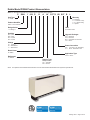
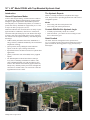
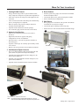
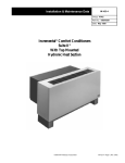
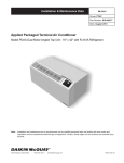
Catalog 1304-1 Packaged Terminal Air Conditioner with Top-Mounted Hydronic Heat Model PGAN - Unit Sizes 007 – 015 Engineered for flexibility and performance™ Contents Daikin Model PGAN Product Nomenclature.............. 3 16" × 42" Model PGAN with Top-Mounted Hydronic Heat................................................................................ 4 Introduction.............................................................. 4 Years of Experience Matter...................................... 4 The Hydronic Experts.............................................. 4 Controls With Built-In Hydronic Logic...................... 4 Quiet Comfort........................................................... 4 More For Your Investment........................................... 5 AHRI Performance Data............................................... 6 Features and Options................................................... 7 Easy To Use Digital Controls................................... 7 Wall Sleeves............................................................ 7 Wall Sleeve Extension............................................. 7 Louver Frame........................................................... 8 Exterior Louvers For Standard Wall Sleeves........... 8 Manual Fresh Air Damper Control........................... 8 Auto Fresh Air Damper Option................................. 8 Positive Condensate Removal................................. 9 Condensate Dispersion System............................... 9 Removable Condenser Fan Motor........................... 9 Freeze Protection..................................................... 9 Seacoast Construction (Option)............................... 9 Permanent Cleanable Filters................................... 9 Unit-Mounted Control................................................. 10 Optional Programmable Electronic Thermostat..... 10 Optional Non-Programmable Electronic Thermostat............................................................. 10 Cooling or Heating – Manual Operation ................ 11 Remote Thermostats............................................. 11 PGAN Dimensions...................................................... 12 Hydronic Heating Configurations............................. 13 Steam..................................................................... 13 Hot Water............................................................... 13 PGAN Supportive Literature: • IM 1193 - Packaged Terminal Air Conditioner, 16" × 42" PGAN with Top-Mounted Hydronic Heat Installation & Maintenance Manual • IM 1196 - Packaged Terminal Air Conditioner - Wall Sleeve Installation, 16" × 42" PGAN with Top-Mounted Hydronic Heat Installation & Maintenance Manual • IM 1198 - Installing The Top-Mounted Hydronic Heat Section To Model PGAN Packaged Terminal Air Conditioner Catalog 1304-1/ Page 2 of 28 Piping........................................................................... 14 Piping..................................................................... 14 How to Select The Correct Wall Cabinet.................. 14 Wall Opening Requirements – 16" × 42"............... 14 Electrical Service................................................... 14 Standard Wall Sleeve Installation.......................... 15 Panel/Window Wall Sleeve Installation.................. 15 NEMA Receptacles................................................ 15 Remote Wall-Mounted Thermostats......................... 17 Remote Thermostat Control................................... 17 Operating Instructions............................................ 17 Thermostat Location.............................................. 18 Remote Thermostat Operation.............................. 18 Non-Programmable Thermostat Specs................. 18 Wall-Mounted, 7, 5-2 & 5-1-1 Programmable Thermostat Specs.................................................. 19 Standard Auto or Manual-Changeover Two-Stage Heat/ Two-Stage Cool Specs................................. 19 Optional Remote Sensor........................................ 20 Energy Saving Options.............................................. 20 Automatic Changeover, Remote Mounted Thermostat............................................................. 20 Wiring Diagrams......................................................... 21 PGAN with Hydronic Heat...................................... 21 PGAN with Hydronic Heat, Optional Power Vent and Power Door..................................................... 22 PGAN with Hydronic Heat, Variable Speed Condenser and Evaporator Fan Motors................. 23 PGAN with Hydronic Heat, Variable Speed Condenser, Evaporator Fan Motors, and Optional Power Vent and Door............................................. 24 Guide Specifications.................................................. 25 Daikin Model PGAN Product Nomenclature Note: For Illustration purposes only. Not all options available with all models. P GAN 1 009 E D A AY YYYYY LB SYY B L Unit Type Warranty P = PTAC A = Standard C = 4 Yr Extnd. Comp. L = 4 Yr Extnd. Refrig. X = Special Product Identifier PGAN = Air Conditioner Design Series SKU 1 = A Design 1 B = Build to Order Unit Size Upgrade Packages 007 = 7,000 009 = 9,000 012 = 12,000 015 = 15,000 SYY = Seacoast AYY = Acoustics BYY = Seacoast and Acoustics YYY = None Voltage A = 115-60-1 E = 208/230-60-1 J = 265/277-60-1 Power Connection LB = Long Cord – 64" (Standard) YY = None - Hardwired to unit Brand Name D = Daikin Application Type YYYYY = None Refrigerant A = R-410A Damper Type Damper Control AY= Automatic MY= Manual Note: An optional unit-mounted thermostat kit or 24 volt wall-mounted thermostat kit is required to operate unit. Catalog 1304-1 / Page 3 of 28 16" × 42" Model PGAN with Top-Mounted Hydronic Heat Introduction Years of Experience Matter As the world’s largest heating, ventilation and air-conditioning manufacturer, Daikin stands behind its product with the strength of a global organization. With Daikin representation and quality U.S. manufactured products; we continue to provide fast delivery and hands-on support that you’ve come to expect to make your project a success. Daikin has added the new model PGAN to its family of packaged terminal air conditioners, ideal for new construction, renovation and replacement projects. The PGAN offers high economic value with a design that delivers energy efficiency, low sound levels and superior reliability, while offering these advantages: • AHRI certified performance that meets ASHRAE-90.1 energy efficiency standards mandated by the United States Department of Energy • Quiet operation, and by adding the sound reduction option, results in a quiet, relaxing environment. • Specialized features and built-in safeties for hydronic heat applications • Quality construction with value-added, factory supplied options • The Standard paint on the PGAN cabinet is Antique Ivory with a contrasting Oxford Brown subbase. This color combination blends well with most interior color schemes. The durable electrostatically applied, baked on, antique ivory urethane powder paint resists smudges and corrosion. For custom colors, refer to Form 2F-1188 and supplemental Form 2F-1188A. Catalog 1304-1/ Page 4 of 28 The Hydronic Experts Daikin is a leading manufacturer of hydronic heat equipment. We specialize in providing hydronic heat with a host of configurable options. Modes • DX Cooling with hot water hydronic heat • DX Cooling with steam hydronic heat Controls With Built-In Hydronic Logic • Normally open/normally closed valve control • Heat fan lockout – prevent the fan from coming on until there is heat in the pipes. Quiet Comfort Our PTAC has been redesigned to be the quietest PTAC we’ve ever built. The unit’s design and construction provide a quiet environment, allowing guests to enjoy peaceful, sleepfilled nights. More For Your Investment 1 Cooling PGAN Chassis 4 Room Cabinet • Energy efficient design with two speed condenser motor, rotary compressor and quiet two speed indoor tangential fan • Filter drier to protect the compressor and lengthen the life of the unit • 100% run tested, and leak-tested during the manufacturing process, and again prior to shipment • Indoor air quality (IAQ) fresh air damper (manual or automatic) and cleanable filter • Optional sound reduction and seacoast package • 64" LCDI safety plug reaches both sides of the chassis • Furniture grade heavy-gauge steel construction with flush mounted touchpad control • Customized depth, colors, grille and kickplate available • Front or bottom return configurations 5 Wall Sleeve • Heavy-gauge steel construction with powder-coated finish in standard or recessed louver design • Customized depth, wall flange and leveling legs • Outside air louver with extruded architectural blade design 5 2 Hydronic Heat Section • Snap on, top-mounted hydronic heat coil (steam or hot water) • Right-hand, left-hand or opposite-end piping configurations for ease of installation • Heat fan lockout – prevents fan operation until there is heat in the pipes • Hydronic control logic for normally open/normally closed valve control • Built-in coil freeze protection for low ambient conditions Wall Flange Wall Sleeve Leveling Legs Architectural Louver 3 Unit-Mounted Digital Controls • Easy to use digital readout when selecting fan mode and speed, mode of operation and temperature display • Optional Non-programmable with auto changeover, fan speed control, hardwired • Optional 7-day programmable with auto changeover, fan speed control, hardwired • Optional remote mounted thermostat controls available 2 3 1 4 Control Blockoff for Wall-Mounted Thermostat Note: An optional unit-mounted thermostat kit or 24 volt wall-mounted thermostat kit is required to operate unit. Catalog 1304-1 / Page 5 of 28 AHRI Performance Data Table 1: AHRI Performance Data(5) Cooling Model 007 009 012 015 BTUH 7200 7600 7600 9000 9000 8800 11700 11700 14000 14000 Sensible BTUH 5300 5700 5700 6000 6000 5900 7800 7800 9400 9400 EER 11.7 11.5 11.5 11.1 11.1 11.1 10.3 10.3 9.6 9.6 Volts 115 230/208 265 115 230/208 265 230/208 265 230/208 265 FLA 7.5 4.1 3.6 8.9 4.7 4.2 6.2 5.4 7.3 6.3 Watts 620 660 660 810 810 790 1140 1140 1460 1460 Cooling Valve & Fan Motor Amps n/a 0.4 0.37 n/a 0.4 0.37 0.4 0.37 0.3 0.31 Min. Circuit Amps 8.9 4.8 4.2 10.7 5.6 4.9 7.4 6.4 8.8 7.6 Hydronic Hot Water BTUH 14300 / 13800 14300 / 13800 14300 / 13800 Heat Steam BTUH 19500 / 19400 19500 / 19400 19500 / 19400 Airflow Time Delay Fuse 15A 15A 15A 15A 15A 15A 15A NEMA Receptacle 5-15R 6-15R n/a 5-15R High Low n/a High 6-15R n/a Low n/a 15200 / 13800 20600 / 20500 15A 15A 15A 6-15R n/a 6-15R n/a High Low High Low Cool - Wet Coil 315 280 n/a 315 280 n/a 315 280 350 315 Heat - Dry Coil 335 300 n/a 335 300 n/a 335 300 370 335 Vent 70 56 n/a 70 56 n/a 70 56 70 56 Note: Actual Vent performance will vary with application and installation conditions. Dehumidification (pints/hr) 1.7 1.7 1.7 2.2 2.2 2.2 3.6 3.6 4.4 4.4 Net Weight (lbs) 103 103 103 107 107 107 107 107 118 118 Ship Weight (lbs) 118 118 118 122 122 122 124 124 135 135 Cabinet/Wall Sleeve (lbs) 36 36 36 Notes: 1.Based on ASHRAE and AHRI test conditions of 95°F DB/75°F WB outside, 80°F DB/67°F WB inside. 2.Based on ASHRAE and AHRI test conditions of 47°F DB outside, 70°F DB inside. 3.All 265 volt models must use a sub-base or be hard-wired with a disconnect switch. 4.Water – Based on ASHRAE and AHRI test conditions of 200°F EWT, 180°F LWT, 70°F EAT with a 1.8 gpm flow rate. 5.Over current protection for all units is 15 amps. 6.Overcurrent protection on 265 volt models must be cartirdge-style time-delay fuses (included and factory installed on all 265 volt chassis. 7.Cooling Full Load Amps includes Compressor, IDF and ODF FLA’s. Catalog 1304-1/ Page 6 of 28 36 Features and Options Easy To Use Digital Controls Figure 2: Wall Sleeve with Recessed Louver Design The optional non-programmable touchpad control offers digital readout and is easy to use when selecting fan speed, mode of operation and temperature setting. A precise digital temperature display provides occupants with an exact comfort setting, thereby eliminating uncomfortable temperature swings and costly overheating/overcooling associated with non-digital electro-mechanical controls. s epth om D Cust m tto o dB e tch Pi Wall Sleeve Extension Figure 1: Optional Non-Programmable or Programmable Digital Touchpad Control, or Remote Thermostat Control The standard wall sleeve will accommodate the maximum wall thickness described in Table 2. For thicker walls, wall sleeve extensions are available from your local distributor. Air splitters will be included in the wall sleeve extension as shown in the illustrations below. Note: When installing a new chassis into an existing wall sleeve with an extension, it will be necessary to relocate the two air splitters to match the dimensions shown in the illustration (see Table 3). Figure 3: Wall Sleeve Extension and Splitter Details B as required Room Side 16" Air Splitters Note: An optional unit-mounted thermostat kit or 24 volt wallmounted thermostat kit is required to operate unit. A Wall Sleeves Constructed of galvanized, phosphatized, heavy-gauge steel with an Antique Ivory powder paint corrosion-resistant finish. Wall sleeves are installed through the wall as shown on the plans and have factory provisions for use of appropriate fastening devices to secure the sleeve to the wall. They can be ordered to custom depths, and recessed louver wall sleeves have a pitched bottom for positive removal of moisture to the outside. An optional factory-welded brickstop flange is provided based on architectural specifications. 42" B C Wall Sleeve Extension Table 2: Maximum Wall Thickness without Sleeve Extensions Maximum Wall Thickness Louver NoStandard Type Subbase Subbase Stamped 3/8" Architectural 11/8" 141/8" 9 1/2" 147/8" 103/8" Table 3: Wall Sleeve Extension Splitter Locations Dimension 16" x 42" A99/16" B245/16" C61/8" Catalog 1304-1 / Page 7 of 28 Features and Options Louver Frame Manual Fresh Air Damper Control Louver frames are used for panel wall and thin wall applications to assure positive anchoring to the wall. The wall sleeve is installed flush with the outside of the building. The louver frame is placed around the wall sleeve. Outdoor fresh air is brought in through a manual damper door, using the control lever, hidden from the occupant's view to allow you to manage ventilation requirements. Figure 7: Manual Fresh Air Damper Control - Left End Figure 4: Louver Frame Dimensions Manual outdoor damper control Vent Closed 183/16" (1072mm) 423/16" (1072mm) 163/16" (411mm) 33/4" (92mm) 443/16" (1122mm) Vent Open Auto Fresh Air Damper Option The optional fresh air damper automatically opens and closes the outdoor air vent door depending on fan operation: Figure 8: Auto Fresh Air Damper Note: Wall Sleeve rough opening when using a Louver Frame must be 165/8" × 425/8" Exterior Louvers For Standard Wall Sleeves Two styles of exterior louvers are available. The standard flush stamped louver is a one-piece stamped aluminum type that is finished natural and clear anodized. Attractive, rugged architectural louvers are extruded aluminum and are finished natural and clear anodized (optional colors are also available). Louvers by others are acceptable as long as they meet factory specifications. They must have a minimum free area of 70% or a pressure drop not exceeding .05 in. w.g. at 300 fpm face velocity, and a blade design that will not cause recirculation of condenser air. Figure 5: Flush Stamped Louver • Opens when the indoor fan is operating to bring in outside air for improved indoor air quality. • Closes when the indoor fan is off to prevent cold drafts. Figure 9: Power Door Kit Figure 6: Architectural Louver Motor shown exploded Catalog 1304-1/ Page 8 of 28 Features and Options Positive Condensate Removal Figure 10: Sloped Basepan & Plastic Drain Pan Removable Condenser Fan Motor Allows easy access to enable regular cleaning of coils, which is essential to maintain unit efficiency and protect the compressor for long unit life. Plastic Drain Pan Base Pan Humidity controls and positive condensate removal features together greatly reduce or eliminate excess condensate. In the process, comfort is improved and energy reduced by using the PGAN’s advanced digital controls to intelligently manage ventilation air and humidity within the conditioned space. Condensate Dispersion System Our condensate dispersion system removes condensate from indoor cooling operation by throwing water directly on to the outdoor coil for rapid evaporation and increased cooling efficiencies. The slinger ring on the new, enhanced fan draws water up and into the fan blades. This water is then atomized and evaporated into the atmosphere through the condenser. Increased surface area from the coil allows more water to be evaporated on the sides of the coils and helps to minimize condensate run-off. Freeze Protection When the unit senses temperatures of 40°F or lower in an unoccupied room, the heat mode is automatically initiated to prevent freezing, and the outdoor fan and compressor are stopped. Seacoast Construction (Option) PGAN units can be ordered with components treated with special coatings that extend the life of the unit dramatically, helping to protect it from corrosive vapors such as salt water vapor, chlorine, and acid vapor. Permanent Cleanable Filters Room side return air is filtered through this permanent, washable polypropylene mesh filter. It is UL listed class II, 38% average arrestance efficiency (ASHRAE test), with low resistance to airflow (0.02 w.g. at 300 cfm), and high dust holding capacity (55 grams). Figure 11: Cleanable Filter • Filters all return air to promote good indoor air quality. • Easy to access and maintain. Catalog 1304-1 / Page 9 of 28 Unit-Mounted Control Optional Programmable Electronic Thermostat Optional Non-Programmable Electronic Thermostat (P/N 910140679) (P/N 910140678) 7-Day Programmable, Auto Changeover, Fan Speed Control, Hardwired Non-Programmable, Auto Changeover, Fan Speed Control, Hardwired ■ ■ ■ ■ ■ ■ ■ ■ ■ ■ ■ ■ 7-Day Programmable Backlit Display Single Stage Heat/Cool Systems Field Calibration Auto Changeover Button Lockout Function Two Speed Fan Control SimpleSet™ Programming Remote Temperature Sensor Capability Title 24 Compliant / No Batteries Required Relay Outputs (minimum voltage drop in thermostat) Ideally Suited for: – Residential (New Construction/Replacement) – Light Commercial Specifications Electrical rating: ■ 24 VAC (18-30 VAC) ■ 1 amp maximum per terminal ■ 3 amp maximum total load Temperature control range: 45°F to 90°F (7°C to 32°C) Accuracy: ± 1°F (± 0.5°C) System configurations: 1-stage heat, 1-stage cool, heat pump Timing: Anti-short Cycle: 5 minutes Backlight Operation: 10 seconds Terminations: C, RH, RC, W, Y, B, O GL, GH, S1, S2 For detailed installation, operation and application refer to Operation & Application Guide LIAF186 Catalog 1304-1/ Page 10 of 28 ■ ■ ■ ■ ■ ■ ■ ■ ■ ■ Backlit Display Single Stage Heat/Cool Systems Field Calibration Auto Changeover Button Lockout Function Two Speed Fan Control Remote Temperature Sensor Capability Title 24 Compliant / No Batteries Required Relay Outputs (minimum voltage drop in thermostat) Ideally Suited for: – Residential (New Construction/Replacement) – Light Commercial Specifications Electrical rating: ■ 24 VAC (18-30 VAC) ■ 1 amp maximum per terminal ■ 3 amp maximum total load Temperature control range: 45°F to 90°F (7°C to 32°C) Accuracy: ± 1°F (± 0.5°C) System configurations: 1-stage heat, 1-stage cool, heat pump Timing: Anti-short Cycle: 5 minutes Backlight Operation: 10 seconds Terminations: C, RH, RC, W, Y, B, O GL, GH, S1, S2 For detailed installation, operation and application refer to Operation & Application Guide LIAF187 Unit-Mounted Control Cooling or Heating – Manual Operation The PGAN internal unit controller has built-in features such as random start, compressor time delay, night setback, load shed, shutdown. The 24 volt low voltage terminal strip is set so R-G energizes the fan. R-W1 energizes the fan and compressor. User Controls A 4 button touch key pad, with a High/Low Fan speed and Auto/On Switch located behind the control door, controls both temperature and operation mode. Thermostat Setting 4-button touchpad with display. Pressing the COOL thermostat control and the down arrows will provide a cooler room temperature. Pressing the HEAT thermostat control and the up arrow keys will provide a warmer room temperature. Power Cord 230/208V and 115V units are equipped with a LCDI power cord and can open the electrical circuit to the unit. In the event the unit does not operate, check the reset button located on or near the head of the power cord as part of the normal troubleshooting procedure. Fan Speed The fan speed selector switch will deliver high, low or auto fan speed to circulate room air. Note: The AUTO selection will not be available if a fan speed is selected without COOL or Heat selection. Fan Operation HIGH or LOW with HEAT or COOL mode selected • The fan will run in the selected speed. • Fan Operation AUTO with HEAT or COOL mode selected - The fan will run in low and high speed. The changes in fan speed are automatic. Remote Thermostats NOTICE When using existing thermostats by others; There are two basic types of thermostats manufactured today; those with relay contacts, and those with solid-state triacs. If you open the thermostat and don't see relays then you can assume it to be solid state. Manufacturers of solid state output thermostats include loading resistors on their installation kits. These are of low Ohm value, approximately 560 Ohm and 3W. The resistors are meant to load the thermostat outputs in order for the output voltage to be either 0 or 24VAC, i.e. no floating voltage. These resistors are connected from W, Y, G to common (C), respectively. Therefore, if you are using existing solid-state thermostats, you may have to add loading resistors for your PTAC controls to work properly. Daikin thermostats do not require this modification. The PGAN unit can be configured to be controlled by a “manufacturer-approved” remote thermostat. When in the remote mode, the unit will only respond to the thermostat inputs (terminal strip positions R, W2, Y/W1, and GH as shown in Figure 12. Figure 12: Remote Thermostat Control Terminals AUXILIARY DS1 DS2 MS1 MS2 EH IN REMOTE THERMOSTAT LS FD1 FD2 TF- TF+ C R C R GL W2 Y/W1 B GH Control Board Connections GL W Y GH Thermostat Connections Notes:In remote mode, the 3-minute compressor time delay, the random restart feature and the freeze protection feature are all active. When a remote wall-mounted thermostat is used, the delay may be a total of 8-minutes. Diagnostic Light - Internal Control Board The green diagnostic light located in the lower left hand corner of the internal control board and indicates operation warnings. This light usually indicates that either the filter or coils need cleaning. Master Switch The master switch disconnects power to all of the system components. When this switch is in the off position, the compressor, fan motor, reversing valve, and electric resistance heater will all be de-energized. Catalog 1304-1 / Page 11 of 28 PGAN Dimensions Figure 13: PGAN Unit Dimensions Programmable Touchpad Controller Note: Electrical rough-in should be located behind kickplate (removable front) and below wall sleeve. Catalog 1304-1/ Page 12 of 28 Hydronic Heating Configurations Steam Hot Water Figure 14: Left-hand supply and return Figure 18: Left-hand supply and return Return Supply Supply Return Figure 19: Right-hand supply and return Figure 15: Right-hand supply and return Return Supply Supply Return Figure 20: Left-hand supply, right-hand return or Righthand supply, left-hand return Figure 16: Right-hand supply, left-hand return Supply Return or Supply Return Return or Supply Figure 17: Left-hand supply, right-hand return Supply Return Note: Piping connections are 5/8" O.D. copper sweat and are symmetrical R.H. or L.H. for same end supply and return. Catalog 1304-1 / Page 13 of 28 Piping Piping Recommended Piping Detail (Field-Installed) Figure 21: Typical Hot Water Coil Piping HFLO Sensor - to be covered with provided insulating cork tape Coil Side View Air Vent Balancing Valve Automatic Valve Gate Valve The minimum cabinet depth is 10.75". This is required because the wall sleeve MUST extend a minimum of 1.625" into the room and 9.125" is required to cover the chassis. This totals 10.75". Standard cabinets range from 10.75" to 18.75" in 1" increments. For other requirements, consult the factory. If the wall sleeve extends into the room more than 1.625", add the inside measurement to the 9.125" required to cover the chassis. This will be the depth of the wall cabinet. For example: The wall sleeve extends 3.25" into room + 9.125" = 12.75" deep cabinet or if the wall sleeve extends 9.25" into room + 9.125" = 18.75" deep cabinet would be the closest fit. Wall Opening Requirements – 16" × 42" Plug to (Control Box) Return Gate Valve Supply Figure 22: Typical Steam Coil Piping Coil HFLO Sensor - to be covered with provided insulating cork tape Side View Automatic Valve Steam Trap Gate Valve Supply Plug to (Control Box) Gate Valve Return Catalog 1304-1/ Page 14 of 28 How to Select The Correct Wall Cabinet When roughing in the opening for the wall sleeve, sufficient clearance from the walls and floor is required. The wall sleeve should be positioned a minimum of 5/8" from the finished side wall to accommodate the room cabinet. A minimum distance of 3" above the finished floor is required for return air. The rough opening should measure 16-1/4" high × 42-1/4" wide. When using a louver frame, the opening must measure 16-5/8" × 42-5/8". Louver frames should be used for panel wall and thin wall applications to provide positive anchoring to the wall. Electrical Service All wiring should be in accordance with all local and National Electrical Code requirements. Units are supplied with an attachment cord and plug which exit from the bottom of the conditioner on the control side. The cord for 115V, 208V and 230V has a usable length of 64" (1626mm) from where it exits the conditioner. The use of extension cords to increase the length of the plug/cord set is not recommended. Units to operate on 265V are supplied with a 18" (457mm) cord for connection to a subbase, or must utilize a hard wired kit. The attachment plug size should be used to determine the circuit ampacity and overcurrent protection. Time delay, overcurrent protection devices are recommended to prevent unit damage and to avoid nuisance tripping. Receptacles are generally located beneath the conditioner, on or recessed in the wall so it is concealed by the conditioner overhang and kickplate (see Figure 13). Typical Installation Types Standard Wall Sleeve Installation Panel/Window Wall Sleeve Installation Masonry Wall Construction Application Wall Sleeve Depth, Wall Thickness, & Optional Continuous Flange Dimensions Notes:1. Wall sleeve to extend a minimum of 1-5/8" past finished sheetrock. 2. Wall sleeve should be recessed the thickness of the louver from face of brick so that when louver is installed it is flush with face of building. Figure 24: Wall Sleeve End View with Continuous Flange and Leveling Leg B (See Table 1) Figure 23: Wall Sleeve End View Using Brickstop Insulation Wet Panel B Window Stool Wood Stool 4" 1-5/8" Metal Stud 16" O.C. Wall Sleeve 1'-4" 2'-4" Brick Optional Flange Outside Louver (See Note 2 above) 3-1/2" Thick Batt Insulation A X D 2'-6-1/2" 13-3/4" Room Cabinet Cabinet Finished Floor 1" Hydronic Heat Coil Section Leveling Leg to Support (Optional) 7-1/4" Exposed Projection Concrete Slab Brick Casement Window with Insulating Clear Glass Table 1: Dimensions for Figure 23 “A” Room Cabinet 183/4 (476 mm) 173/4 (451 mm) 163/4 (425 mm) 153/4 (400 mm) 143/4 (375 mm) 133/4 (349 mm) 123/4 (324 mm) 113/4 (298 mm) 103/4 (273 mm) 103/4 (273 mm) 103/4 (273 mm) 103/4 (273 mm) 103/4 (273 mm) “D” Wall Sleeve “B” Wall Thickness 133/4 (349 mm) 133/4 (349 mm) 133/4 (349 mm) 133/4 (349 mm) 133/4 (349 mm) 133/4 (349 mm) 133/4 (349 mm) 133/4 (349 mm) 133/4 (349 mm) 143/4 (375 mm) 153/4 (400 mm) 163/4 (425 mm) 173/4 (451 mm) 43/4–53/4 (121–146 mm) 53/4–63/4 (146–171 mm) 63/4 –73/4 (171–197 mm) 73/4 –83/4 (197–222 mm) 83/4 –93/4 (222–248 mm) 93/4 –103/4 (248–273 mm) 103/4 –113/4 (273–298 mm) 113/4 –123/4 (298–324 mm) 123/4 –133/4 (324–349 mm) 133/4 –143/4 (349–375 mm) 143/4 –153/4 (375–400 mm) 153/4 –163/4 (400–425 mm) 163/4 –173/4 (425–451 mm) Notes:1. Flange dimension “X” is “as required” and is usually provided to the factory to be secured to wall sleeve during fabrication. 2. Dimension "B" is wall thickness (see Table 1). 3. Given dimensions are standard. *These are typical but may be adjusted upon request by contacting your local Daikin Representative. NEMA Receptacles Standard Size Wall Sleeve Gr Gr Gr Gr 1 to 2-3/8" dia. 1-3/8" dia. 1-3/8" dia. 2-1/8" dia. 7-20R5-20R6-20R6-30R 20 Amp, 265V 20 Amp, 120V 20 Amp, 202V 30 Amp, 250V Catalog 1304-1 / Page 15 of 28 Wall-Mounted Thermostats – Quick Selection Guide Table 2: Wall Mounted Thermostats – Quick Selection Guide 910116771 910116772910116774 Thermostat Item Number • • • Single Stage Two Stage • Heat Pump • • • Manual Changeover (Cool/Off/Heat) • • • Settable Differential Range • • • Auto Changeover • Status LEDs • Backlit Display • • • 7-Day or 5-2 day or 5-1-1 Programmable • • Temporary Hold • • Programmable Fan On/Off Delay • Non-Programmable • Hard Wired • • • Wireless 4 or 5 Wire Capable • • • Freeze Protection • Fan Switch - On/Auto • • • Lockout Feature • • Fahrenheit or Celsius Display • • • Remote Sensor Option • Power Loss Memory Protection • • • Anti-Short Cycle Delay • • • Max/Min. Set Point Control • • Energy Management Interface California Title 24 Compliant • • • Catalog 1304-1/ Page 16 of 28 Remote Wall-Mounted Thermostats Remote Thermostat Control The Remote Thermostat can be any thermostat that can interface with an electronic thermostat via RCBWYG terminals. The Internal Control Board (ICB) must be configured for C1 and L5, and the thermostat wiring harness connected to the thermostat and remote thermostat pins on the ICB. During a call the remote thermostat will pass R back to the controller on a respective terminal. However, the control pad LED display will indicate the mode of operation, and the room temperature. Notes: In terms of outputs, there are two types of thermostats: relay contacts and solid state. If you open the thermostat and don’t see relays then it must be solid state. Manufacturers of solid state output thermostats include loading resistors on their installation kits. They are of 560 Ohm and 3W value. These resistors are meant to load thermostat solid state outputs in order for the output voltage to be either 0 or 24VAC, i.e. no floating voltage. These resistors are connected from W, Y, G to common (C), respectively. You can wire any type of 24Vac thermostat straight into the REMOTE T’STAT connector Internal Control Board. Operating Instructions Cooling or Heating – Manual Operation The PGAN unit controller has built-in features such as random start, compressor time delay, night setback, load shed, shutdown. The 24 volt low voltage terminal strip is set so R-G energizes the fan. R-W1 energizes the fan and compressor. User Controls A 4 button touch key pad, with a High/Low Fan speed and Auto/On Switch located behind the control door, controls both temperature and operation mode. Thermostat Setting 4-button touchpad with display. Pressing the COOL thermostat control and the up or down arrows will provide a cooler room temperature. Pressing the HEAT thermostat control and the up or down arrow keys will provide a warmer room temperature. LCDI Power Cord 230/208V and 115V units are equipped with a LCDI power cord and can open the electrical circuit to the unit. In the event the unit does not operate, check the reset button located on or near the head of the power cord as part of the normal troubleshooting procedure. Fan Speed The fan speed selector switch will deliver high, low or auto fan speed to circulate room air. Fan Operation HIGH or LOW with HEAT or COOL mode selected • The fan shall run in the selected speed. • Fan Operation AUTO with HEAT or COOL mode selected - The fan will run in low and high speed. The changes in fan speed are automatic. Diagnostic Light - Internal Touchpad The green diagnostic light located in the lower left hand corner of the touchpad and indicates operation warnings. This light usually indicates that either the filter or coils need cleaning. Master Switch The master switch disconnects power to all of the system components. When this switch is in the off position, the compressor, fan motor, reversing valve, and electric resistance heater will all be de-energized. NOTICE When using existing thermostats by others; There are two basic types of thermostats manufactured today; those with relay contacts, and those with solid-state triacs. If you open the thermostat and don't see relays then you can assume it to be solid state. Manufacturers of solid state output thermostats include loading resistors on their installation kits. These are of low Ohm value, approximately 560 Ohm and 3W. The resistors are meant to load the thermostat outputs in order for the output voltage to be either 0 or 24VAC, i.e. no floating voltage. These resistors are connected from W, Y, G to common (C), respectively. Therefore, if you are using existing solid-state thermostats, you may have to add loading resistors for your PTAC controls to work properly. McQuay thermostats do not require this modification. To operate this unit with a “manufacturer-approved” remote thermostat, configure the control to be operated by the remote thermostat. Enter configuration mode C1 and then select option Code L5. When in the remote mode, the unit will only respond to the thermostat inputs (terminal strip positions GL (or GH), W2, Y/W1, and B* shown in “Control Board User Inputs” illustration). Notes: Once configuration C1 with option code L5 has been selected, the control touchpad will no longer accept inputs other than configuration and diagnostics modes. The room occupant must operate the unit at the remote mounted thermostat. In remote mode, the 3-minute compressor time delay, the random restart feature and the freeze protection feature are all active (see Unit Features section). When remote wall-mounted thermostat is used, the delay may be a total of 8-minutes. Note: The AUTO selection will not be available if a fan speed is selected without COOL or Heat selection. Catalog 1304-1 / Page 17 of 28 Remote Wall-Mounted Thermostats Thermostat Location Non-Programmable Thermostat Specs This unit is designed to be operated with remote wall mounted thermostats. For further information on thermostats approved for use with this unit, contact your sales representative. For best performance results, the thermostat should be located approximately five feet above the floor on a vibration free, inside wall in an area with good air circulation. Do not install the thermostat where it may be affected by the following: • Dead spots behind doors, in corners or under cabinets • Hot or cold drafts from air ducts • Radiant heat from the sun, appliances, or fireplaces • Concealed pipes and chimneys • Unheated (uncooled) areas behind the thermostat, such as an outside walls Consult the instruction sheet packaged with the thermostat for further details on mounting and operation. Figure 25: Internal Control Board - Remote Control Terminations AUXILIARY DS1 DS2 MS1 MS2 EH IN REMOTE THERMOSTAT LS FD1 FD2 TF- TF+ C R GL W2 Y/W1 B GH Control Board Connections C R GL W Y GH Thermostat Connections Remote Thermostat Operation Approved thermostats vary slightly in construction and, with few exceptions, are operated similarly. The following operational description pertains to approved non-programmable thermostats that energize G in Heat and Cool mode. Heat/Off/Cool Switch • OFF - cooling and heating functions are defeated. • HEAT - the selected room temperature is maintained by cycling the hydronic control valve. • COOL - the selected room temperature is maintained by cycling the air conditioner. Table 3: Maximum Wire Length for Remote Control Connection Maximum Wire Length Wire Size (AWG) Maximum Length Allowed #24 400 ft. #22 600 ft. #20 900 ft. #18 1500 ft. #16 2000 ft. Catalog 1304-1/ Page 18 of 28 Manual Changeover One-Stage Heat and Cool or One-Stage Heat Pump Part No. 910116771 (1-Pk, White with Wall Plate) Simple to operate, single push button for one-stage heating and cooling, or single stage heat pump. Zone compatible and 4- or 5 wire compatible (terminal “C” is optional for non-heat pump systems). System “heat-off-cool” switch and fan “onoff” switch. Specifications Electrical Rating: • 24 VAC (18 to 30 VAC) • 1 amp maximum per terminal • 3 amp maximum total load • 30-minute power loss memory retention Temperature Control Ranges: • 45°F to 90°F, Accuracy: ± 1°F System Configurations: • 1 stage heat, 1 stage cool or single stage electric heat pump Terminations: • R, C, W, Y, O, B, G Remote Wall-Mounted Thermostats Wall-Mounted, 7, 5-2 & 5-1-1 Programmable Thermostat Specs Standard Auto or Manual-Changeover TwoStage Heat/ Two-Stage Cool Specs Manual Changeover One-Stage Heat and Cool or One-Stage Heat Pump Part No. 910116774 (1-Pk, White with Wall Plate) Part No. 910116772 (1-Pk, White with Wall Plate) Specifications Specifications Electrical Rating: • 24 VAC (18 to 30 VAC) • 1 amp maximum per terminal • 3 amp maximum total load • 30-minute power loss memory retention • Easy access terminal block Temperature Control Ranges: • 45°F to 90°F, Accuracy: ± 1°F System Configurations: • 1 stage heat, 1 stage cool or single stage electric heat pump Terminations: • RC, RH, C, W, Y, O, B, G Electrical Rating: • 24 VAC (18 to 30 VAC) • 1 amp maximum per terminal • 4 amp maximum total load • 30-minute power loss memory retention • Easy access terminal block Temperature Control Ranges: • 45°F to 90oF, Accuracy: ± 1°F System Configurations: • Single or two-stage heat/cool • Single or two-stage heat pump Terminations: • R, C, W1/O/B, Y1, W2, Y2, G Catalog 1304-1 / Page 19 of 28 Remote Wall-Mounted Thermostats Optional Remote Sensor Part No. 107096010 (Used in Conjunction with Thermostat Part No. 910116774 Only) The Fast, Easy Solution For Temperature Sensing Problems. • For tamper prone areas • Poor airflow areas • Troubled applications • Foam gasket prevents drafts through wall opening • Mounts to standard 2" × 4" outlet box • 23/4"W × 41/2"H Energy Saving Options Automatic Changeover, Remote Mounted Thermostat Thermostats can be obtained to switch from heating to cool ing and from cooling to heating automatically. With automatic changeover, the operation of the heating cycle or the cooling cycle is determined by the temperature requirement of the space. Most thermostats with this feature are set to changeover when the room temperature varies 3-1/2°F from the set-point. The unit is placed in the cooling mode when the set-point is over 3-1/2°F; 3-1/2°F under the set point places the unit in the heating mode. This 3-1/2°F variation is usually adjustable from a 1/2°F dead band to a 5°F dead band. Each cycle is run until the set point temperature is reached, then that cycle is de-energized. On some thermostats, the automatic changeover function can be overridden manually by moving the thermostat selector switch to “heat” or to “cool.” The fan operation, with an automatic changeover thermostat, is controlled by the fan selector switch. When placed in the “fan” mode, the fan runs continuously. When placed in the “auto” mode, the fan will only energize when the thermostat calls for heating or cooling. • Program Setback Control With the Programmable Touchpad, four (4) different periods, Morn., Day, Eve., or Nite, can be independently programmed for start time, Heat setting and Cool setting. There are additional energy savings with Programmed Setback Control. Catalog 1304-1/ Page 20 of 28 • Fresh Air Dampers Daikin Packaged Terminal conditioners can be furnished with an automatic fresh air damper in lieu of a manual fresh air damper. The automatic damper is wired in parallel to the indoor fan relay. When the Fan Switch is placed in the ON mode, the fan and damper cycle as the thermostat cycles. Wiring Diagrams PGAN with Hydronic Heat BK BK 7 LINE 2 LINE 1 HEATER 1 HEATER 2 BK RD COMPRESSOR BK BL RD BK R RD 7 RS 485 COM TO MOTOR GND 230/265 VSTM OD FAN HIGH FAN LOW REV VALVE HIGH VOLTAGE! DISCONNECT ALL POWER BEFORE SERVICING OR INSTALLING THIS UNIT. MULTIPLE POWER SOURCES MAY BE PRESENT. FAILURE TO DO SO MAY CAUSE PROPERTY DAMAGE, PERSONAL INJURY OR DEATH. FOR A HEAT PUMP THERMOSTAT USED ON A STRAIGHT COOL UNIT GL - LOW SPEED GH - HIGH SPEED OUTDOOR FAN MOTOR COMPRESSOR EVAPORATOR MOTOR FAN CAPACITOR FUSE HIGH PRESSURE SWITCH HEATER ELEMENT RELAY RUN CAPACITOR FOR COMPRESSOR AND FAN RVC REVERSING VALVE TRANSFORMER TR VSM VARIABLE SPEED MOTOR VSTM VARIABLE SPEED TERMINAL BOARD CM COMP EM FC F HPS HTR R RCCF 7 Outdoor Motor Speed Selection Model or Mfg. # Starts With MTC15 High Speed VSTM Black Low Speed VSTM Red 1650 1350 IO-440 02/2013 Wiring is subject to change. Catalog 1304-1 / Page 21 of 28 Wiring Diagram PGAN with Hydronic Heat, Optional Power Vent and Power Door OR LINE 1 HEATER 1 HEATER 2 LINE 2 COMPRESSOR R VSTM OD RS485 COM 230/265 GND TO MOTOR FAN HIGH FAN LOW PK RD REV VALVE RD PK 6 PK VT GY BR HIGH VOLTAGE! DISCONNECT ALL POWER BEFORE SERVICING OR INSTALLING THIS UNIT. MULTIPLE POWER SOURCES MAY BE PRESENT. FAILURE TO DO SO MAY CAUSE PROPERTY DAMAGE, PERSONAL INJURY OR DEATH. FOR A HEAT PUMP THERMOSTAT USED ON A STRAIGHT COOL UNIT GL - LOW SPEED GH - HIGH SPEED OR Outdoor Motor Speed Selection Model or Mfg. # Starts With High Speed VSTM Black Low Speed VSTM Red 1650 1350 MTC15 CM COMP EM FC F HPS HTR R RCCF 7 Catalog 1304-1/ Page 22 of 28 OUTDOOR FAN MOTOR COMPRESSOR EVAPORATOR MOTOR FAN CAPACITOR FUSE HIGH PRESSURE SWITCH HEATER ELEMENT RELAY RUN CAPACITOR FOR COMPRESSOR AND FAN RVC REVERSING VALVE TR TRANSFORMER VSM VARIABLE SPEED MOTOR VSTM VARIABLE SPEED TERMINAL BOARD IO-441 2/2013 Wiring is subject to change. Wiring Diagram PGAN with Hydronic Heat, Variable Speed Condenser and Evaporator Fan Motors FAN HIGH BK RS485 COMPRESSOR RD RD LINE 1 HEATER 1 HEATER 2 BK LINE 2 WH VT BK WH BK 1650 1500 1350 1170 RS485 COM TO MOTOR 230/265 VSTM OD GND VSM CM FAN MOTOR WH BK RD COM VSTM ID 230/265 GND VSM EM EVAP MOTOR TO MOTOR FAN LOW REV VALVE HIGH VOLTAGE! DISCONNECT ALL POWER BEFORE SERVICING OR INSTALLING THIS UNIT. MULTIPLE POWER SOURCES MAY BE PRESENT. FAILURE TO DO SO MAY CAUSE PROPERTY DAMAGE, PERSONAL INJURY OR DEATH. FOR A HEAT PUMP THERMOSTAT USED ON A STRAIGHT COOL UNIT GL - LOW SPEED GH - HIGH SPEED OR Indoor Motor Speed Selection Model or Mfg. # Starts With CM COMP EM FC F HPS HTR R RCCF 7 OUTDOOR FAN MOTOR COMPRESSOR EVAPORATOR MOTOR FAN CAPACITOR FUSE HIGH PRESSURE SWITCH HEATER ELEMENT RELAY RUN CAPACITOR FOR COMPRESSOR AND FAN RVC REVERSING VALVE TR TRANSFORMER VSM VARIABLE SPEED MOTOR VSTM VARIABLE SPEED TERMINAL BOARD High Speed VSTM Black Low Speed VSTM Red MTC07 1400 1250 MTC09 1400 1250 MTC12 1400 1250 Outdoor Motor Speed Selection Model or Mfg. # Starts With High Speed VSTM Black Low Speed VSTM Red MTC07 1350 1170 MTC09 1350 1170 MTC12 1350 1170 IO-788 2/2013 Wiring is subject to change. Catalog 1304-1 / Page 23 of 28 Wiring Diagram PGAN with Hydronic Heat, Variable Speed Condenser, Evaporator Fan Motors, and Optional Power Vent and Door OR RS485 RS485 LINE 1 HEATER 1 HEATER 2 LINE 2 COMPRESSOR COM 230/265 VSTM OD COM TO MOTOR 230/265 VSTM ID GND VSM CM FAN MOTOR WH GND VSM EM EVAP MOTOR TO MOTOR FAN HIGH WH FAN LOW PK RD REV VALVE RD PK 6 PK VT GY BR HIGH VOLTAGE! DISCONNECT ALL POWER BEFORE SERVICING OR INSTALLING THIS UNIT. MULTIPLE POWER SOURCES MAY BE PRESENT. FAILURE TO DO SO MAY CAUSE PROPERTY DAMAGE, PERSONAL INJURY OR DEATH. FOR A HEAT PUMP THERMOSTAT USED ON A STRAIGHT COOL UNIT GL - LOW SPEED GH - HIGH SPEED OR Indoor Motor Speed Selection Model or Mfg. # Starts With CM COMP EM FC F HPS HTR R RCCF 7 Catalog 1304-1/ Page 24 of 28 OUTDOOR FAN MOTOR COMPRESSOR EVAPORATOR MOTOR FAN CAPACITOR FUSE HIGH PRESSURE SWITCH HEATER ELEMENT RELAY RUN CAPACITOR FOR COMPRESSOR AND FAN RVC REVERSING VALVE TRANSFORMER TR VSM VARIABLE SPEED MOTOR VSTM VARIABLE SPEED TERMINAL BOARD High Speed VSTM Black Low Speed VSTM Red MTC07 1400 1250 MTC09 1400 1250 MTC12 1400 1250 Outdoor Motor Speed Selection Model or Mfg. # Starts With High Speed VSTM Black Low Speed VSTM Red MTC07 1350 1170 MTC09 1350 1170 MTC12 1350 1170 IO-789 2/2013 Wiring is subject to change. Guide Specifications Furnish and install where shown on plans packaged terminal air conditioners of the sizes and capacities shown on the schedule. The units shall be located as shown on the drawings and shall include cabinet/wall sleeve, chassis, outdoor louver, hydronic heat section, valve, and room cabinet. All units shall be ETL listed for safety and AHRI certified for performance. Overall dimensions for the basic unit shall not exceed 52" wide, 22-1/2" high, and 17-3/4" deep. Overall dimensions of the wall sleeve shall be 16" high, 42" wide and (13-3/4"/______) deep. All units shall operate on ______ volts, 60 Hz, 1 phase power. (Units furnished with hydronic heat shall not exceed 43" wide, 24-1/2" high and 20" deep). The minimum energy efficiency ratio (EER) in BTU per hour per watt for each PGAN unit must be in compliance with ASHRAE 90.1 replacement or new construction criteria, for all sizes using R-410A Refrigerant. Cooling chassis – Chassis shall be slide-in, plug-in type with a self-contained, hermetically sealed refrigerant circuit. All chassis sheet metal parts shall be constructed of either powder-coated A-60 or A-60 galvanized steel for maximum corrosion resistance. The chassis shall consist of the following components: Vibration isolated compressor; rifled copper tubed evaporator and condenser coils with high efficiency raised lance aluminum plate fins mechanically expanded to the tubes for maximum heat transfer; and a capillary restrictor type refrigerant metering device. Hydronic coils shall be factory tested at 450 psig, and 600 psig for refrigerant coils. A positive closing (manual or optional automatic) fresh air damper may be located within the chassis to provide fresh air during fan operation. Airflow system shall include separate fan motors for the condenser and evaporator sections. The condenser fan motor shall be a variable-speed, totally enclosed, permanently lubricated fan motor. Condenser fan shall be propeller-type with a slinger ring and shall be constructed of aluminum. The indoor fan motor shall be a two-speed, totally enclosed; permanently lubricated fan motor must be positioned on the indoor side of the bulkhead so as to be completely within the conditioned, filtered airstream. The indoor blower fan shall be a forward-curved tangential design to provide even airflow across the evaporator coil. During the cooling cycle: The compressor, the outdoor fan motor and the indoor fan motor shall be energized. Condensation accumulated on the evaporator coil shall be drained into the outdoor section where it is to be picked up by the condenser fan/slinger ring and evaporated against the outdoor coil. In the cool mode, the compressor will cut in if the space temperature is at least 1°F above the thermostat set point and will cut out when the space temperature is approximately 2°F below set point, subject to timing protections. During the heating cycle: Hydronic Heat – Only the indoor fan motor, the (normally open) (normally closed) valve and optional automatic fresh air damper shall be energized. The outdoor condenser fan motor and compressor shall not be energized. When the control is in the heat mode and calling for heat, the indoor fan shall not turn on until the HFLO sensor is above 100°F. If at any time while the unit is in heat mode the HFLO sensor is below 90°F, the indoor fan shall turn off immediately. Control will check if the HFLO sensor temperature is above 100°F for 2 seconds before resuming indoor fan operation. Control module – The PGAN Control module is used to control a PGAN unit that includes both an integral air conditioner and a source of heat. The Digital Control is operated with a unit mounted thermostat or 24 volt, Wall Mounted Thermostat. Room freeze protection – When the unit senses temperatures of 40°F or lower in an unoccupied room, the heat mode is automatically initiated to prevent freezing. The outdoor fan and compressor are stopped to help prevent coil freeze. Compressor protection – The life of the compressor is extended through built in protection logic such as: • High temperature protection if the compressor temperature exceeds 154°F • Minimum run time • Minimum off time • Random restart after a power outage Inputs and outputs The PGAN control module offers the following inputs: 1. Indoor Coil Sensor (ICS) 2. Indoor Air Sensor (IAS) 3. Inputs from Remote Thermostat (R, B, G, Y, W) 4. Heat Fan Lock Out Sensor (HFLO) 5. Power Supply, 24VAC Catalog 1304-1 / Page 25 of 28 Guide Specifications The PGAN control module offers the following outputs: 1. Compressor Output 2. Outdoor Fan 3. Indoor Fan Fan cycle or Fan Continuous and Blower Hi or Blower Lo shall be incorporated to allow either continuous or automatic fan cycle operation at the selected fan speed. When choosing automatic fan cycle operation, the fan shall be energized only when the Indoor Fan is operating. 4. Damper Control 5. Hydronic Valve Digital Control – Shall have solid state digital control operated via a unit mounted thermostat or remote wall mounted thermostat. Shall include space temperature control and unit ON or OFF, and the following: Cooling – Compressor and Outdoor fan, Indoor fan – HI, LOW, CONSTANT or FAN CYCLE, Auto Fresh Air damper (optional). Heating – Hydronic Valve, Indoor fan – HI, LOW, CONSTANT or FAN CYCLE, Auto Fresh Air damper (optional). Room Cabinet – Shall be flat top, wrap-around design with a heavy-gauge sheet metal front panel that is phosphatized and coated with a baked on, corrosion resistant finish. Room cabinets with ordinary enamel finish are not acceptable. Discharge grilles shall be tamper-proof. The control access door shall be mounted on the right-hand side. Optional Fresh Air Damper – A positive closing automatic fresh air damper must be located within the chassis to provide fresh air during fan operation. It will be configurable for selection of AUTO operation or CLOSED. Filtration (Standard) – Room side return air shall be completely filtered through a permanent, washable polypropylene mesh filter. Foam type filters are not acceptable. Filter must be a UL listed class II, 38% average arrestance efficiency (ASHRAE test) air filter with low resistance to airflow (0.02 w.g. at 300 CFM) and high dust holding capacity of 55 grams. Wall Sleeve – Shall be entirely constructed of galvanized, phosphatized, heavy-gauge steel with an Antique Ivory powder paint corrosion resistant finish. Unpainted, galvanized steel wall sleeves with or without rust inhibiting spray are not acceptable. Wall sleeves with ordinary enamel finish are not acceptable. Wall sleeves shall be installed through the wall as shown on plans and shall have factory provisions for use of appropriate fastening devices to secure sleeve to the wall. In no event shall fasteners be installed through the basepan in the bottom of the cabinet/wall sleeve. Outside Air Louvers – Shall be (stamped) (architectural) anodized aluminum as shown on plans. Louver shall be (finished natural) (painted) as shown on the schedule. Louvers shall be easily installed from the inside of the building after the cabinet/ wall sleeve has been installed. Special field fabricated louvers must be approved by the PTAC manufacturer as to free area and air circulation requirements. Catalog 1304-1/ Page 26 of 28 Catalog 1304-1 / Page 27 of 28 Daikin Training and Development Now that you have made an investment in modern, efficient Daikin equipment, its care should be a high priority. For training information on all Daikin HVAC products, please visit us at www.daikin.com and click on Training, or call 540-248-9646 and ask for the Training Department. Warranty All Daikin equipment is sold pursuant to its standard terms and conditions of sale, including Limited Product Warranty. Consult your local Daikin Representative for warranty details. Refer to Form 933430285Y. To find your local Daikin Representative, go to www.daikin.com. Aftermarket Services To find your local parts office, visit www.daikin.com or call 800-37PARTS (800-377-2787). To find your local service office, visit www.daikin.com or call 800-432-1342. This document contains the most current product information as of this printing. For the most up-to-date product information, please go to www.daikin.com. Products manufactured in an ISO certified facility. ©2013 Daikin Applied • www.DaikinApplied.com • (800) 432-1342 IM 1304-1 (10/13)