1
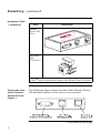
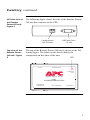
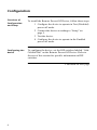
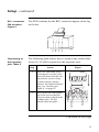
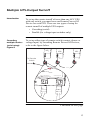
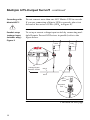
Remote
Power-Off
Device
AP9830
Thank You!
Thank you for selecting the Remote Power-Off Device (AP9830). It has been designed for
many years of reliable, maintenance-free service in combination with your American
Power Conversion (APC) uninterruptible power supply (UPS). APC is dedicated to the
development of high-performance electrical power conversion and control products. We
hope that you will find this product a valuable, convenient addition to your computing
system.
Please read this manual! It provides important safety, installation, and operating
instructions that will help you get the most from your Remote Power-Off Device.
Save this manual! It includes instructions for obtaining warranty service.
Contents
Overview . . . . . . . . . . . . . . . . . . . . . . . . . . . . . . . . . . . . . . . 1
Introduction 1
Features of the Remote Power-Off Device 1
Hardware requirements 2
Safety warning 2
Inventory . . . . . . . . . . . . . . . . . . . . . . . . . . . . . . . . . . . . . . . 3
Inventory 3
Server-side view of the Remote Power-Off unit 4
UPS-side view of the Remote Power-Off unit 5
Top view of the Remote Power-Off unit 5
Configuration . . . . . . . . . . . . . . . . . . . . . . . . . . . . . . . . . . . . 6
Overview of Configuration and Setup 6
Configuring the device 6
Power-off condition—DIP switches #1 & #2 7
Power-off mode—DIP switch #3 8
DIP switch #4 8
Setup . . . . . . . . . . . . . . . . . . . . . . . . . . . . . . . . . . . . . . . . . . 9
Introduction 9
Connecting the Remote Power-Off Device 9
Switch types 10
Keystone jack PIN locations 10
RJ11 connector PIN locations 11
Connecting to the keystone jack 11
Placement of accessories 12
Warning 12
Continued on next page
i
Contents, continued
Multiple UPS-Output Turnoff . . . . . . . . . . . . . . . . . . . . . . . . . 13
Introduction 13
Cascading multiple devices (serial setup) 13
Cascading with Matrix-UPS™ 14
Parallel setup (voltage input switches only) 14
No parallel setup for contact closure switches 15
Specifications . . . . . . . . . . . . . . . . . . . . . . . . . . . . . . . . . . . . 16
Remote switch requirements 16
Cable requirements 16
Warning 16
Product specifications 17
Ordering additional components 17
ii
Overview
Introduction
American Power Conversion’s Remote Power-Off Device
(AP9830) is an accessory that allows you to turn off the output of an APC™ uninterruptible power supply ( UPS) by a
remote switch. In many facilities the UPS is not readily
accessible. With the Remote Power-Off Device, you can
immediately turn off the UPS output with a switch you have
placed in a convenient location.
For remote turnoff of more than one UPS by a single switch,
you can set up each UPS with its own Remote Power-Off
Device. For further information, see “Multiple UPS-Output
Turnoff” on page 13.
Features of
the Remote
Power-Off
Device
The Remote Power-Off Device:
• Provides instantaneous remote turnoff of APC UPS
output
• Works with a variety of switches—normally open,
normally closed, and applied voltage
• Can be set up for shutting down multiple UPSs with
one switch (one Remote Power-Off Device for each
UPS)
• Supports all functions normally available to the UPS,
including the powering of accessories, smart signaling, and UPS Turn-on/Turn-off
i
Continued on next page
1
Overview continued
Hardware
requirements
The Remote Power-Off Device requires:
Safety warning
Wiring safety is the responsibility of those installing the
cable and remote switch. Incorrect installation can result in
improper functioning of the device or damage to hardware.
The use of substandard cables can produce toxic fumes in
the event of a fire.
2
• An APC Smart-UPS®, Matrix-UPS™ or the
Symmetra™ PowerArray™
• A switch (SELV or Class 2 circuit). See “Switch
types: Table 4” on page 10.
• A cable for connecting the remote switch to the
Remote Power-Off Device. See “Cable requirements” on page 16.
Inventory
Inventory:
Table 1
The Remote Power-Off Device consists of the parts listed in
the following table.
Item
Illustration
DB9-DB9
Cable (APC
part number
940-0064)
RJ11 Cable,
10 ft
(607-0035)
RJ11 Cable,
6 in.
(607-0036)
Table 1: Inventory
Continued on next page
3
Inventory continued
Inventory: Table
1 continued
Item
Illustration
Remote
Power-Off
Unit
FF
R-OEST
WE / T
PO
N
S
UP
TO
TIO
RA
IGU
NF
CO
w
ww
.a
c.
co
m
E
VIC
E
FD
-OF
0
983 ER
APPOW
TE
MO
E
SR
UP
pc
CA
O/
SC
E
AD
T
U
EO
AD
SC
CA
IN
RP
OR
ER IES
RV OR
SEESS
C
TO
AC
Keystone
Jack
(750-0023)
Velcro® strip for optional mounting of the Remote Power-Off unit.
Server-side view
of the Remote
Power-Off unit:
Figure 1
The following figure shows the side of the Remote PowerOff unit that connects to the server or accessories.
Figure 1:Server-side view of the Remote Power-Off unit
Continued on next page
4
Inventory continued
UPS-side view of
the Remote
Power-Off unit:
Figure 2
The following figure shows the side of the Remote PowerOff unit that connects to the UPS.
1 2 3 4
Configuration
DIP Switches
DB9 Male Port –
To UPS
Figure 2:UPS-side view of the Remote Power-Off unit
Top view of the
Remote PowerOff unit: Figure
3
The top of the Remote Power-Off unit is shown in the following figure. The labels on the decal identify the
components on the sides of the unit.
LED
CONFIGURATION
TO UPS
POWER-OFF
/ TEST
w w w. a p c c . c o m
AP9830
UPS REMOTE POWER-OFF DEVICE
TO SERVER OR
ACCESSORIES
RPO / CASCADE IN
CASCADE OUT
Figure 3:Top view of the Remote Power-Off unit
5
Configuration
Overview of
Configuration
and Setup
To install the Remote Power-Off Device, follow these steps:
Configuring the
device
To configure the device, set the DIP switches labeled “CONFIGURATION” on the Remote Power-Off Device. Refer to
the rest of this section for specific information on DIP
switches.
1 Configure the device to operate in Test (Disabled)
power-off mode.
2 Connect the device according to “Setup” on
page 9.
3 Test the device.
4 Configure the device to operate in the Enabled
power-off mode.
Continued on next page
6
Configuration continued
Power-off
condition — DIP
switches #1 &
#2: Table 2
DIP switches 1 and 2 govern the power-off condition for the
Remote Power-Off Device. Refer to the table below to set
DIP switches 1 and 2.
Note: A contact closure switch toggles between an open and
closed circuit. A voltage input switch applies and
removes a voltage signal. For requirements, see
“Switch types: Table 4” on page 10.
Position†
Switch Type
Contact Closure
(PINs 2, 5)
Voltage Input
(PINs 3, 4)
DIP
#1
DIP
#2
A normally closed
(N.C.) contact
closure opens
24V is removed
from the voltage
input
1
0
A normally open
(N.O.) contact
closure closes
24V is applied to the
voltage input
0
1
0
0
INVALID
INVALID
1
1
Table 2: Power-off condition — DIP switches #1 & #2
† 0 = ↑, 1 = ↓
Continued on next page
7
Configuration continued
Power-off mode
— DIP switch
#3: Table 3
DIP switch 3 governs the power-off mode for Remote
Power-Off Device operation. Refer to the following table
for a description of the power-off modes.
Power-Off
Mode
Position†
Purpose
Test
(Disabled)
0
Check wiring between
the remote switch and
the Remote Power-Off
Device
Enabled
1
Normal operation
Table 3: Power-off mode — DIP switch #3
Power-Off
Asserted
No
Yes
† 0 = ↑, 1 = ↓
In either power-off mode, the Remote Power-Off Device
LED appears lit when the device is properly connected and
configured and the remote switch is being asserted.
DIP Switch #4
8
DIP switch #4 is unassigned.
Setup
Introduction
This section shows how to connect the Remote Power-Off
Device. After setup, continue with the procedure in “Overview of Configuration and Setup” on page 6.
If you are setting up multiple Remote Power-Off Devices
for use with one remote switch, refer to this section for basic
information on wiring and see “Multiple UPS-Output Turnoff” on page 13.
Connecting the
Remote PowerOff Device:
Figure 4
Follow the figure below to set up the Remote Power-Off
Device. Note that the RJ11 cable connects to the middle
port of the unit, which is labeled “RPO / Cascade In.”
Server
To
Remote
Switch
APC UPS
Cable Supplied with
Remote Power-Off
Device
Keystone
Jack
Remote
Power-Off
Unit
RJ11
Cable
Cable Supplied with
PowerChute Software
Figure 4:Connecting the Remote Power-Off Device
Continued on next page
9
Setup continued
Switch types:
Table 4
The requirements and PIN assignments for the remote
switch vary according to the type of switch being used:
Requirements
Contact
Closure
• Safety Extra Low Voltage
(SELV) or Class 2 circuit
• Switch or relay properly
isolated from the utility
• Latching
Voltage
Input
2, 5
• SELV or Class 2 circuit
• Switched 24V AC/DC
• Latching
Table 4: Switch types
Keystone jack
PIN locations:
Figure 5
RPO/Cascade In
PIN Assignment
Type
3, 4
The PIN locations for the keystone jack appear in the figure
below.
Figure 5:keystone jack PIN locations
Continued on next page
10
Setup continued
RJ11 connector
PIN locations:
Figure 6
The PIN locations for the RJ11 connector appear in the figure below.
Figure 6:RJ11 connector PIN locations
Connecting to
the keystone
jack: Table 5
The following table shows how to connect the switch cable
wires (26–22 AWG required) to the keystone jack.
Step
Action
1
Place the individual wires
(unstripped) over the cylinders associated with the wiring scheme you are using
(contact closure scheme
shown). For further information, see “Switch types:
Table 4” on page 10.
2
Press down the clear plastic
top of the jack so that the
wires become wedged in the
cylinder slits. The top
should click into place.
Figure
Table 5: Connecting to the keystone jack
Figure 7:Connecting to the keystone jack
Continued on next page
11
Setup continued
Placement of
accessories
The Remote Power-Off Device works effectively with all
APC accessories, provided that the accessory is connected
to the Remote Power-Off Device through the DB9 port
labeled “TO SERVER OR ACCESSORIES.”
Warning
Do not connect any external APC UPS accessory between
the Remote Power-Off Device and the UPS. An accessory
connected between the Remote Power-Off Device and the
UPS may be able to turn on the UPS during a remote poweroff condition.
12
Multiple UPS-Output Turnoff
Introduction
To set up the remote turnoff of more than one APC UPS
with one switch, you must have one Remote Power-Off
Device for each UPS. There are two types of setup for
remote turnoff of multiple UPS outputs:
• Cascading (serial)
• Parallel (for voltage input switches only)
Cascading
multiple devices
(serial setup):
Figure 8
To set up either type of remote switch (contact closure or
voltage input) by cascading Remote Power-Off Devices,
refer to the figure below.
UPS1
To Remote
Switch
UPS2
UPSn
TO UPS
TO UPS
TO UPS
CONFIGURATION
CONFIGURATION
CONFIGURATION
w w w. a p c c . c o
m
RPO / CASCADE IN
POWER-OFF
/ TEST
POWER-OFF
/ TEST
POWER-OFF
/ TEST
w w w. a p c c . c o
w w w. a p c c . c o
m
TO SERVER OR
ACCESSORIES
RPO / CASCADE IN
m
AP9830
UPS REMOTE POWER-OFF
DEVICE
AP9830
UPS REMOTE POWER-OFF
DEVICE
AP9830
UPS REMOTE POWER-OFF
DEVICE
TO SERVER OR
ACCESSORIES
TO SERVER OR
ACCESSORIES
RPO / CASCADE IN
CASCADE OUT
CASCADE OUT
CASCADE OUT
w w w. a p c c . c o
...
m
AP9830
PS REMOTE POWER-OFF
DEVICE
RPO / CASCADE IN
CASCADE OUT
Figure 8:Cascading multiple devices (serial setup)
Continued on next page
13
Multiple UPS-Output Turnoff continued
Cascading with
Matrix-UPS™
Do not connect more than one APC Matrix-UPS in cascade.
If you are connecting a Matrix-UPS in cascade, place it at
the end of the series of UPSs (UPSn in Figure 8).
Parallel setup
(voltage input
switches only):
Figure 9
To set up a remote voltage input switch by connecting multiple Remote Power-Off Devices in parallel, refer to the
figure below.
UPS1
UPSn
POWER-OFF
/ TEST
w w w. a p c c . c o
m
AP9830
UPS REMOTE POWER-OFF
DEVICE
TO SERVER OR
ACCESSORIES
RPO / CASCADE IN
CASCADE OUT
TO UPS
CONFIGURATION
POWER-OFF
/ TEST
w w w. a p c c . c o
m
TO UPS
CONFIGURATION
AP9830
UPS REMOTE POWER-OFF
DEVICE
TO SERVER OR
ACCESSORIES
RPO / CASCADE IN
POWER-OFF
/ TEST
CASCADE OUT
w w w. a p c c . c o
m
AP9830
UPS REMOTE POWER-OFF
DEVICE
TO SERVER OR
ACCESSORIES
To
Voltage Input
Remote Switch
PIN 3
RPO / CASCADE IN
CASCADE OUT
...
PIN 4
RJ11
Cable
Keystone
Jack
PIN 3
PIN 4
Figure 9:Parallel setup (voltage input switches only)
Continued on next page
14
Multiple UPS-Output Turnoff continued
No parallel
setup for
contact closure
switches
Do not connect more than one Remote Power-Off Device
contact closure circuit to the same remote switch. Doing so
may cause damage to associated equipment. To connect
multiple Remote Power-Off Devices to the same contact
closure switch, see “Cascading multiple devices (serial
setup): Figure 8.”
15
Specifications
Remote switch
requirements
For remote switch requirements, see “Switch types: Table
4” on page 10.
Cable
requirements
The Remote Power-Off Device comes with two RJ11
cables. Some users may choose to use existing building
cables. The cable that connects the Remote Power-Off
Device to the remote switch must be UL listed, 26-22 AWG,
and one of the following types:
• CL2 Class 2 cable for general use
• CL2P Plenum cable for use in ducts, plenums, or
other space used for environmental air
• CL2R Riser cable for use in a vertical run in a shaft or
from floor to floor
• CL2X Limited-use cable for use in dwellings or in
raceway
For installations in Canada, the cable must be CSA certified,
type ELC (extra-low-voltage control cable).
Warning
Wiring safety is the responsibility of those installing the
cable. Incorrect installation can result in improper functioning of the device or damage to hardware. The use of
substandard cables can produce toxic fumes in the event of
a fire.
Continued on next page
16
Specifications continued
Product
specifications:
Table 6
The product specifications for the Remote Power-Off Device
appear in the following table.
Item
Specification
Size of unit (h × w × l)
2.5 × 6.1 × 9.7 cm
1.0 × 2.4 × 3.8 in
Length between remote switch
and unit
3 m normal, 60 m max.
10 ft normal, 200 ft max.
Length between cascaded units
3 m normal, 60 m max.
10 ft normal, 200 ft max.
Maximum number of cascaded
units
10
Power required
24VDC @ 35mA, powered
by UPS port
Table 6: Product specifications
Ordering
additional
components
To order additional components, contact APC at the number
on the back cover of this manual. You may also contact the
American Power Conversion Web site.
17
Limited Warranty
American Power Conversion (APC) warrants the Remote Power-Off Device to be free
from defects in materials and workmanship for a period of two years from the date of purchase. Its obligation under this warranty is limited to repairing or replacing, at its own sole
option, any such defective products. This warranty does not apply to equipment which has
been damaged by accident, negligence, or misapplication or has been altered or modified
in any way. This warranty applies only to the original purchaser.
To obtain service under warranty you must obtain a Returned Material Authorization
(RMA) number from APC or a designated APC service center. Products must be returned
to APC or an APC service center with transportation charges prepaid and must be accompanied by a brief description of the problem encountered and proof of date and place of
purchase.
EXCEPT AS PROVIDED HEREIN, AMERICAN POWER CONVERSION MAKES
NO WARRANTIES, EXPRESS OR IMPLIED, INCLUDING WARRANTIES OF MERCHANTABILITY AND FITNESS FOR A PARTICULAR PURPOSE. Some states do
not permit limitation or exclusion of implied warranties; therefore, the aforesaid limitation(s) or exclusion(s) may not apply to the purchaser.
EXCEPT AS PROVIDED ABOVE, IN NO EVENT WILL APC BE LIABLE FOR
DIRECT, INDIRECT, SPECIAL, INCIDENTAL, OR CONSEQUENTIAL DAMAGES
ARISING OUT OF THE USE OF THIS PRODUCT, EVEN IF ADVISED OF THE POSSIBILITY OF SUCH DAMAGE. Specifically, APC is not liable for any costs, such as
lost profits or revenue, loss of equipment, loss of use of equipment, loss of software, loss
of data, costs of substitutes, claims by third parties, or otherwise. This warranty gives you
specific legal rights and you may also have other rights which vary from state to state.
Life support policy
As a general policy, APC does not recommend the use of any of its products in life
support applications where failure or malfunction of the APC product can be reasonably
expected to cause failure of the life support device or to significantly affect its safety or
effectiveness. APC does not recommend the use of any of its products in direct patient
care. APC will not knowingly sell its products for use in such applications unless it
receives in writing assurances satisfactory to APC that (a) the risks of injury or damage
have been minimized, (b) the customer assumes all such risks, and (c) the liability of
American Power Conversion is adequately protected under the circumstances.
Examples of devices considered to be life support devices are neonatal oxygen analyzers,
nerve stimulators (whether used for anesthesia, pain relief, or other purposes), autotransfusion devices, blood pumps, defibrillators, arrhythmia detectors and alarms, pacemakers,
hemodialysis systems, peritoneal dialysis systems, neonatal ventilator incubators, ventilators for both adults and infants, anesthesia ventilators, and infusion pumps as well as any
other devices designated as “critical” by the U.S. FDA, or other competent authority.
Hospital grade wiring devices and leakage current may be ordered as options on many
APC UPS systems. APC does not claim that units with this modification are certified or
listed as Hospital Grade by APC or any other organization. Therefore these units do not
meet the requirements for use in direct patient care.
w w w. a p c c . c o m
Toll free technical support:
Addresses:
U. S. & Canada
Austria
Belgium
Czech Republic
Denmark
Finland
France
Germany
Holland
Hungary
Ireland
Israel
Italy
Japan
Luxembourg
Norway
Poland
Portugal
South Africa
Spain
Sweden
Switzerland
Turkey
U. K.
American Power Conversion Corporation
132 Fairgrounds Road
P. O. Box 278
West Kingston, Rhode Island 02892
USA
1-800-800-4272
0660 6480
0800 15063
0 800 102063
800 18 153
9800 13 374
0 800 906 483
01300818907
0800 0224655
00800 12221
1 800 702000 x 2045
177 353 2206
1678 74731
0120-80-60-90
0800 2091
800 11 632
00800 353 1202
050 553182
0800 994206
900 95 35 33
020 795 419
0800 556177
0800 35390275
0800 132990
American Power Conversion Corporation
(A. P. C.) b. v.
Ballybritt Business Park
Galway
Ireland
American Power Conversion
BR Gotanda 7th Floor
2-30-4 Nishi-gotanda,
Shinagawa-ku
Tokyo 141 Japan
Areas without toll free numbers:
+1 401 789 5735 (USA) or
+353 91 702020 (Ireland)
+7095 916 7166 (Russia)
Serial number:
Entire contents copyright © 1998 American Power Conversion. All rights reserved.
Reproduction in whole or in part without permission is prohibited.
All trademarks are the property of their respective owners.
990-0197
Rev. 1
7/98