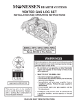
1
Vented Gas Log Set
Models: VWF18, VWF24,
VWF30, VWF36
WARNINGS
Installation and Operating
277300
Instructions
VWF log cover
If the information in this manual is not
followed exactly, a fire or explosion may result
causing property damage, personal injury or
loss of life.
– Do not store or use gasoline or other
flammable vapors and liquids in the
vicinity of this or any other appliance.
– WHAT TO DO IF YOU SMELL GAS
• Do not try to light any appliance.
• Do not touch any electrical switch; do
not use any phone in your building.
• Immediately call your gas supplier from
a neighbor's phone. Follow the gas
supplier's instructions.
• If you cannot reach your gas supplier,
call the fire department.
– Installation and service must be performed
by a qualified installer, service agency or
the gas supplier.
This gas log set is to be installed only in a
solid-fuel burning fireplace with a working flue
constructed of noncombustible material.
INSTALLER: Leave this manual with the appliance.
CONSUMER: Retain this manual for future reference.
27D8520 1/13 Rev. 14
VWF Series Vented Gas Log Set
CONTENTS
Thank you and congratulations on your purchase of a Vermont Castings Group Log Set.
PLEASE READ THE INSTALLATION AND OPERATION INSTRUCTIONS BEFORE USING THE APPLIANCE!
IMPORTANT: Read all instructions and warnings carefully before starting installation.
Failure to follow these instructions may result in a possible fire hazard and will void the warranty.
Important Safety Information .................................... 3
Product Specifications .............................................. 4
Gas Specifications..................................................... 4
Gas Pressures........................................................... 4
Minimum Hearth Dimensions..................................... 4
Getting Started .......................................................... 5
Placement in a Fireplace with a Restrictive Barrier 6
Installation .................................................................. 7
Damper Stop Installation............................................ 7
Before Installing the Appliance................................... 7
Install Valve Cover....................................................... 8
Wiring - Millivolt........................................................... 9
Check System Operation........................................... 9
Connect the Gas ....................................................... 10
Manual Control........................................................11
Millivolt Control.......................................................11
Log Placement .......................................................... 12
Fill the Burner Pan................................................... 12
VWF18 Massive Oak Log Placement...................... 12
VWF24 Massive Oak Log Placement...................... 14
VWF30 Massive Oak Log Placement...................... 15
VWF36 Massive Oak Log Placement...................... 17
VWF18 American Oak Log Placement..................... 19
VWF24 American Oak Log Placement..................... 20
VWF30 American Oak Log Placement..................... 21
VWF24B Log Placement.......................................... 23
VWF24/18 Split River Oak Log Placement.............. 24
VWF30/24 Split River Oak Log Placement.............. 26
VWF36/30 Split River Oak Log Placement.............. 28
VWF18 Split Pine Placement................................... 30
VWF24 Split Pine Placement................................... 33
VWF30 Split Pine Placement................................... 35
VWF24/18WP Weathered Pine Log Placement....... 37
VWF30/24WP Weathered Pine Log Placement....... 39
WF36/30WP Weathered Pine Log Placement......... 41
Operating Instructions.............................................. 43
Manual Control Lighting Instructions . ..................... 43
Millivolt Control Lighting Instructions . ..................... 44
Flame Appearance..................................................... 45
Fireplace Draft Test................................................... 46
Remote Control Receiver Replacement.................. 47
Cleaning and Servicing . .......................................... 47
Replacement Parts ................................................... 48
Assembly.................................................................. 48
Massive Oak Logs.................................................... 49
American Oak Logs.................................................. 50
Birch Logs................................................................ 50
Split River Oak Logs................................................ 50
Split Pine Logs......................................................... 51
Weathered Pine Logs............................................... 52
Massachusetts Residents Only............................... 54
Warranty..................................................................... 56
27D8520
IMPORTANT SAFETY INFORMATION
OWNER
Please leave these instructions with the appliance.
Please retain these instructions for future reference.
WARNING
Read these instructions carefully before
installing or trying to operate this vent-free
gas heater.
This product must be installed by a licensed
plumber of gas fitter when installed within
the Commonwealth of Massachusetts.
• Any change to this heater or its controls can be dangerous.
• Improper installation or use of the heater can cause serious injury or death from
fire, burns, explosion or carbon monoxide poisoning.
• Do not allow fans to blow directly into the stove. Avoid any drafts that alter burner
flame patterns.
• Do not use a blower insert, heat exchanger insert or other accessory, not approved
for use with this heater where applicable.
1. The installation, combustion and ventilation air
must conform with local codes or, in the absence of
local codes, with the National Fuel Gas Code, ANSI
Z223.1.
2. Installation and repair should be done by a qualified
service person. Vermont Castings Group Vented Gas
Logs must be installed only in a masonry or a UL 127
solid-fuel fireplace with minimum venting requirements,
see installation section.
3. To prevent malfunction, gas log set and flue should
be cleaned at least annually by a professional service
person. More frequent cleaning may be required due
to excessive lint from carpeting, etc. It is imperative
that control compartments, burners and circulating air
passageways be kept clean.
4. A damper clamp must be installed to provide the
minimum permanent vent opening to vent flue
products, Refer to installation instructions.
5. Never burn solid fuels in a fireplace where a gas log
set is installed.
6. This appliance must not be used with glass doors
in the closed position. A fireplace screen must be
in place when the log set is burning. Provisions for
adequate combustion air must be provided. Adequate
combustion air usually results in all flames curling into
the fireplace away from screen and up the flue.
8. Keep room area clear and free from combustible
materials, gasoline and other flammable vapors and
liquids.
9. Children and adults should be alerted to the hazard
of high surface temperature and should stay away to
avoid burns or clothing ignition.
27D8520
10. Young children should be carefully supervised when
they are in the same room with the gas log set in operation.
11. Do not place clothing or other flammable material near
the fireplace when the gas logs are in use.
12. Do not use this gas log set if any part has been underwater. Immediately call a qualified service technician
to inspect the gas logs and replace any part of the
control system and any gas control which has been
under water.
13. The gas log set must be isolated from the gas supply
piping system by closing its individual manual shutoff
valve during any pressure testing of the gas supply
piping system at test pressures equal to or less than
1/2 psig (3.5kPa).
14. Secure gas log set to fireplace.
15. This log set will burn off the paint on the front grate
bar. Note: See cleaning section for refurbishing.
16. FOR MASSACHUSETTS RESIDENTS ONLY:
Installation of this vented gas log in the Commonwealth
of Massachusetts requires the damper be permanently
removed or welded in the full open position. In addition, a
naturally vented gas log may not be installed in a bedroom
or bathroom in the Commonwealth of Massachusetts. Flex
line installation must not exceed 36".
WARNING
WARNING
INSTALLER
IMPORTANT
VWF Series Vented Gas Log Set
This appliance is for installation only in
a solid fuel burning fireplace (masonry
fireplace or manufactured fireplace).
Product specifications
VWF Series Vented Gas Log Set
Model
VWF18N
VWF18P
VWF24N
VWF24P
VWF30N
VWF30P
VWF36N
VWF36P
Fuel
Natural
LP
Natural
LP
Natural
LP
Natural
LP
Control
Manual
Manual
Manual
Manual
Manual
Manual
Manual
Manual
Nominal
BTU/h
60,000
60,000
70,000
60,000
80,000
60,000
80,000
60,000
WARNING
Gas Specifications
GAS pressures
Manifold Pressure
Max. Gas Inlet Pressure
Min. Gas Inlet Pressure
Natural Propane (LP)
4.0” w.c.
10.0” w.c.
10.0” w.c. 13.0” w.c.
4.0" w.c.
10.0" w.c.
Never connect unit to private (nonutility) gas wells. This gas is commonly
known as wellhead gas.
VWF18, VWF24, WF30, VWF36
Certified To
ANSI Z21.60 Latest Edition
&
CSA 2.26 Latest Edition
NOTE: Actual performance, flame height, Btu/hr will vary
with specific installation, gas pressure, shutoff valve position (fully open), valve type and firebox draft conditions.
Manual Control
Model
A
B
VWF18 21” 13Z\x”
VWF24 27” 13Z\x”
VWF30 33” 13Z\x”
VWF36 39” 13Z\x”
C
24”
30”
36”
42”
Millivolt Control*
Model
A
B
VWF18 25” 13Z\x”
VWF24 31” 13Z\x”
VWF30 37” 13Z\x”
VWF36 43” 13Z\x”
C
28”
34”
40”
46”
*Use this chart for
SRO and WP Manual
Control Logs
Figure 1 Minimum Hearth Dimensions
FP2725
min hearth dims
27D8520
GETTING STARTED
Check your packing list to verify that all listed parts have
been received. You should have the following:
BURNER - GRATE ASSEMBLY 18", 24", 30", 36"
• Burner and Grate Weldment Assembly
• Lava Rocks (x2)
• Extenders w/ Knob (Manual Control Only)
• Glowing Embers (Rock Wool)
• Damper Clamp
• Vermiculite
• Installation /Operating Instructions
• 3/8" Aluminum Tube with 3/8" 90° elbow, 1/2” to
•
•
3/8” tube fitting
Shield Plate
Control Cover
18", 24", 30" OR 36" ceramic fiber or refractory logs
• Individual Logs
• Installation Instructions
Carefully inspect the contents for shipping damage. If any
parts are missing or damaged, immediately inform the
dealer from whom you purchased the appliance. Do not
attempt to install any part of the appliance unless you
have all parts in good condition.
Minimum Free Opening Area of Chimney Damper for Venting
WARNING
Make sure you have received all parts
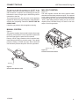
VWF Series Vented Gas Log Set
The fireplace and gas logs function as
a system. If the fireplace is not drafting
properly and spilling into the room (check
with a match or a smoke stick), reposition
the damper clamp until the positive draft is
obtained by opening the damper. If negative
pressure in home prevents having a positive
draft, contact your dealer for assistance.
MINIMUM CHIMNEY HEIGHT and flue
opening
Chimney Height
Flue Opening
6'
64 sq in
8'
64 sq in
10'
64 sq in
15'
51 sq in
20'
51 sq in
30'
51 sq in
ITEMS REQUIRED FOR INSTALLATION
Ensure that the following items are available before proceeding with installation:
• External regulator (for propane/L.P.G. only)
• Shutoff valve
• Pipe wrench
• Piping which complies with local codes
• Drill with masonry bit (for mounting to the floor)
• Pipe sealant approved for use with propane/L.P.G.
(Resistant to sulfur compounds)
WARNING
• Handle the gas log burner assembly by
the grate only. Do not pick the unit up
by the burner. Burner pan is a separate
assembly.
• Gloves are recommended when handling
ceramic fiber logs to prevent skin
irritation from loose fibers. Logs are
fragile — handle with care.
27D8520
VWF Series Vented Gas Log Set
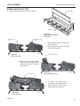
Placement in a fireplace with a restrictive barrier
Important information for the installation of this gas log
set
The following are guidelines for placing a VWF log set in a fireplace that has a restrictive barrier
along the bottom front opening of the fireplace. Some examples of barriers are glass/screen door
frames and sunken/recessed fireplaces.
Height of Restriction (X)
No Restriction
0 to 1Z\x"
Greater than 1Z\x" to 3"
Greater than 3"
Minimum Depth of Fireplace/Firebox
13" Manual Control
13Z\x" Millivolt Control
15"
15"
Any barrier greater than three inches (3") placed in front of the gas log set is not recommended by the manufacturer
The log set should be placed against
or as near as possible to the rear wall
of the fireplace/firebox.
Glass door frames with
adjustable louvers should
have the lovers fully open
while the unit is in operation.
Height of restrictive barrier caused X
by glass door frames, recessed
fireplaces, etc. from the base or
bottom surface of the unit. (See Table).
Depth of fireplace/firebox.
(Refer to Table).
Barriers such as the bottom of a glass door
frame placed in front of a gas log FP2726
set can
restriction depth change the air flow characteristics of the
fireplace which in turn can cause the unit
to overheat and malfunction. Any deviation
from the installation guidelines on this sheet
will potentially void the warranty.
CAUTION
WARNING
Figure 2
If the fireplace has a restrictive barrier
and is equipped with a remote receiver, it
must be placed outside of the combustion
chamber. Refert to Remote Control Receiver
Installation Page 49.
NOTE: Noncombustible material such as refractory brick
may be used to line the floor of the fireplace in order to
raise the height of the gas log set in relation to a restrictive
barrier.
27D8520
INSTALLATION
VWF Series Vented Gas Log Set
Install and operate the appliance
as directed in this manual.
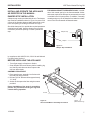
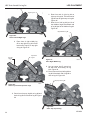
Damper stop installation
A damper stop must be provided with the unit. The damper
stop must be installed as shown in Figure 3 to prevent full
closure of the fireplace damper blade and provide a minimum flue opening, according to the table on Page 5.
Should the clamp not fit, or provide the required permanent
opening from the table, have the damper cut to provide
a minimum permanent opening or install a permanent
stop.
FOR MASSACHUSETTS RESIDENTS ONLY: Installation of this vented gas log in the Commonwealth of Massachusetts requires the damper be permanently removed
or welded in the full open position. In addition, a naturally
vented gas log may not be installed in a bedroom or bathroom in the Commonwealth of Massachusetts.
Damper Stop
Damper
Figure 3 Damper Stop Installation
In compliance with ANSI Z21.60, CSA 2.26 and National
Fuel Gas Code, Section 6.
FP2727
FP2727
damper
Before installing the appliance
• Turn off gas supply to fireplace or firebox.
• Clean fireplace floor and chimney before installing log
set. Seal any ash clean out doors to protect the
unit from down drafts.
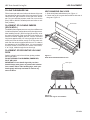
Assembly procedure
1. Place grate/burner assembly into firebox with
the front pan facing forward.
2. Drill two (2) 5/32" diameter holes approximately
1Z\x" deep.
3. Anchor the front pan to the floor using the screws
provided.
Proper installation of the grate is essential to
prevent any movement of the gas logs and
controls during operation.
FP2728
Screws
Figure 4 Secure Grate/Burner Assembly into Firebox
Injector
(Natural Gas Only)
FP2728
secure burner assy
27D8520
INSTALLATION
VWF Series Vented Gas Log Set
Covers must be installed prior to operation
to prevent overheating.
NOTICE
WARNING
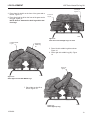
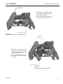
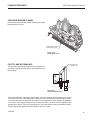
INSTALL VALVE COVER
Grate bar must not touch the valve.
Valve
Cover
Valve Cover
Grate Bar
LG1040
Manual
Control Valve
Figure 5 Place Manual Control Valve Cover
LG1040
valve cover
Grate
LG1043
Figure 6 Place Millivolt Control
Valve Cover
LG1043
Millivolt Control
Valve
millivolt cover
27D8520
VWF Series Vented Gas Log Set
Label all wires prior to disconnection when
servicing controls. Wiring errors can cause
improper and dangerous operation. Verify
proper operation after servicing
WARNING
WARNING
WIRING - MILLIVOLT
Do not connect to 110 Volt supply
Millivolt Control Valve
Pilot
LG1044
The Millivolt (thermopile) is a self powered combination gas
control that does not require 110V AC to operate. Refer to
Figure 7 and installation instructions provided with optional
wall switch or remote control for wiring instructions. A maximum length of 15 feet of 18 awg two conductor wire is to
be used for wall switch. NOTE: Switches must be suitable
for millivolt operation. The optional wall switch must be
mounted outside the firebox. The remote receiver location
must not exceed a temperature of 120°LG1044
F.
Check System Operation
Keep wiring away from heat source and
hot surfaces.
Millivolt valve wiring diagram
The millivolt system and individual components may be
checked with a millivolt meter having a 0-1000mV range.
Conduct each check shown in chart below by connection
meter test leads to terminals as indicated.
A.Complete Millivolt System Check
("A" Reading - contacts CLOSED - Control
Knob "ON" - Main burner should be come
ON)
a. If the reading is more than 100 millivolts and the
automatic valve still does not come on — replace
the control.
b. If the closed circuit reading (“A” reading) is less
than 100 millivolts, determine cause for low reading
— proceed as follows:
27D8520
WARNING
Figure 7 Millivolt Control Valve Wiring Diagram
Check
To Test
Test
A
Complete
System
B
Thermopile
Output
Connect
Meter
Leads to
Terminals
TH & TH/TP
Meter
Reading
Should Be
Min. 100 mV
TP & THTP
Min. 325 mV
B.Thermopile Output Reading Check
(“B” Reading - contacts OPEN - Main
burner OFF)
a. 325 millivolts minimum. If the minimum millivolt reading is not obtainable, readjust pilot for maximum millivolt output. If millivolt reading is still below minimum
specified, replace thermopile.
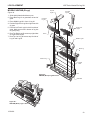
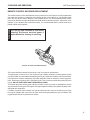
CONNECT THE GAS
CAUTION
NOTICE: A qualified gas appliance installer
must connect the appliance to the gas
supply. Consult all local codes before installation.
WARNING
NOTICE
VWF Series Vented Gas Log Set
Connecting directly to an unregulated propane/
LPG tank can cause an explosion.
Use new black iron pipe, steel pipe, copper tubing, or internally tinned copper tubing.
Copper or internally tinned copper tubing can only according to the National Fuel
Gas Code, section 2.6.3, providing gas meets sulfide limits, and where permitted by
local codes. Gas piping system must be sized to provide minimum inlet pressure
at the maximum flow rate (Btu/hr). Undue pressure loss will occur if the pipe is
too small.
A manual shutoff valve must be installed upstream of the appliance. Union tee
and plugged 1/8" NPT pressure tapping point should be installed upstream of the
appliance. Figure 8
Pipe Coupling
Gas Supply Inlet
To Gas Log Set or
to Gas Valve
Shutoff
Valve
Locations that the Pressure
Tapping Point May be Installed
IMPORTANT: Hold appliance firmly with a wrench to prevent movement when connecting to inlet piping.
Always use an external regulator for all propane/LPG
gas logs only, to reduce the supply tank pressure to a
maximum of 13.0" w.c. High pressure natural gas systems
require a regulator to reduce supply pressure to 10.0”
w.c.
Pipe
Figure 8 Gas Line Connection
FP2739
gas connection
10
27D8520
CONNECT THE GAS
VWF Series Vented Gas Log Set
The gas log set gas inlet connection is 3/8" NPT at the
regulator, inlet on the right side facing the gas log. If a left
side connection is required, the connecting pipe may be
led under the rear of the gas logs or behind the grate for
connection to the inlet.
Test all gas joints from the gas meter to the appliance
regulator for leaks using a gas analyzer or soap and water
solution after completing connection. DO NOT USE AN
OPEN FLAME.
Millivolt Control
Figure 10
The valve regulator controls the burner pressure which
should be checked at the pressure test point. Turn captured
screw counter clockwise 2 or 3 turns and then place tubing
to pressure gauge over test point (Use test port labeled
“OUT”). After taking pressure reading, be sure and turn
captured screw clockwise firmly to re-seal. Do not over
torque. Check for gas leaks.
Check the gas pressure with the appliance burning.
Manual Control
Figure 9
The pressure regulator is preset and locked to discourage
tampering. If the pressure is not as specified, replace with
the correct part from the parts list in this manual.
Remove 1/8" NPT plug, located on side of regulator body.
Install fitting and tubing to pressure gauge. After taking
pressure reading, re-install test plug. which should be
checked at the pressure test point. Check for gas leaks.
LG1046
Test Port “Out”
Figure 10 Pressure Test Point Location
LG1046
millivolt control valve
Test Plug
Figure 9 Pressure Test Point Location
LG1045
LG1045
manual control valve
27D8520
11
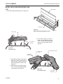
LOG PLACEMENT
VWF Series Vented Gas Log Set
filling THE burner pan
Fill the burner pan with vermiculite to the bottom of the rear
log and sloped to the front edge of the burner pan. Excess
vermiculite can spill forward or to the side of the burner
pan. Do not overfill the propane model. Do not cover the
pilot (if SPK or MVVK is installed) with vermiculite or rock
wool (embers).
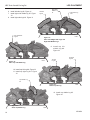
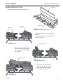
VWF18 massive oak logs
1. Slide shield plate behind burner pan. Figure 11
2. Center rear log #1 on grate bars and flush with rear of
the grate. Figure 12
Shield Plate
placement of glowing embers
(rock wool)
The Wildfire flame appearance can vary due to differences
in draft and fireplace configurations and ember placement.
After installing rear (#1) and front logs (#2 and #3), cover
the entire top surface of the vermiculite in the burner pan
with the rock wool supplied with unit. Tear the rock wool
into pieces approximately 1/2" in size (roughly the size of a
nickel) and cover the burner evenly. Do no use more rock
wool than the amount supplied with the unit. To enhance
the appearance of the Wildfire flame, it is recommended
to form a mound of rock wool in the center of the burner,
2" to 3" high, visible through the two front logs.
Placement of Decorative Volcanic
Rock
Sprinkle volcanic rock in front of front glowing embers
and to both sides.
DO NOT SPRINKLE ON BURNERS, EMBER BED,
PILOT OR LOGS.
IMPORTANT: Do not handle logs with your bare
hands! Always wear gloves to prevent skin irritation
from ceramic fibers. After handling logs, wash your
hands gently with soap and water to remove any
traces of fibers.
Burner Pan
LG837
Figure 11 Slide Shield Plate Behind Burner Pan
Rear Log #1
LG837
VWF18 shield plate
LG838
Figure 12 Center Rear Log #1 on Grate Bars
LG838
VWF18MO rear log
12
27D8520
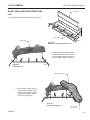
LOG PLACEMENT
VWF Series Vented Gas Log Set
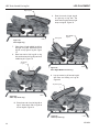
Front Right
Log #3
3. Place front left log #2 on the front of the grate and to
the left. Figure 13
4. Place front right log #3 on the front of the grate and to
the right. Figure 13
NOTE: Allow 2" between the back log and the two
front logs.
Front Left
Log #2
LG839
Figure 13 Place Front Left and Right Logs on Grate
Left Side Middle
Log #4
Right Side
Middle Log
#5
LG839
VWF18MO front logs
5. Place left side middle log #4 as shown.
Figure 14
6. Place right side middle log (#5). Figure
14
Right Top
Log #6
Figure 14 Place Right and Left Side Middle Logs
LG840
Lg840
Place logs
right top log #5 as
VWF18MO7.
middle
shown. Figure 15
Figure 15 Place Right Top Log
27D8520
LG841
VWF18MO top log
LG841
13
LOG PLACEMENT
VWF Series Vented Gas Log Set
VWF24 massive oak logs
Shield Plate
1. Slide shield plate behind burner pan. Figure 16
2. Center rear log #1 on grate bars and flush with rear of
the grate. Figure 17
Rear Log #1
Burner Pan
Figure 16 Slide Shield Plate Behind Burner Pan
Figure 17 Center Rear Log on Grate Bars
LG842
LG830
VWF24 shield
Front Left Log #2
LG830
Front Right
Log #3
LG842
3. Place
front left log #2 on the front of the
VWF24MO
rearleft.
logFigure 18
grate
and to the
4. Place front right log #3 on the front of
the grate and to the right. Figure 18
NOTE: Allow 2" between the back
log and the two front logs.
Left Middle
Log #4
LG843
Figure 18 Place Front Logs
LG843
VWF24MO front logs
5. Place left side middle log #4 as
shown. Figure 19
Figure 19 Place Left Middle Log
LG846
27D8520
14
LG846
VWF24MO left log
LOG PLACEMENT
Left Side
Middle Log #4
VWF Series Vented Gas Log Set
Right Side Middle
Log #5
6. Place right side middle log #5
as shown. Figure 20
7. Place left top log #7 as shown.
Figure 20
Right Top Log #6
Figure 20 Place Right Side Middle Log and Left Top Log
LG844
LG844
VWF24MO middle logs
8. Place right top log #6 as
shown. Figure 21
Figure 21 Place Right Top Log
VWF30 massive oak logs
LG845
1. Slide shield plate down back of burner pan. Figure 22
2. Center rear
log #1 on
LG845
grate bars
and
flush
VWF24MO
top log
with rear of the grate.
Figure 23
Shield Plate
Rear Log #1
Burner Pan
Figure 22 Slide Shield Plate Behind Burner Pan
27D8520
LG801
shield plate
LG801
Figure 23 Center Rear Log on Grate
LG847
VWF30MO rear log
LG847
15
LOG PLACEMENT
VWF Series Vented Gas Log Set
Front Left Log #2
Front Right Log #3
3. Place front left log #2 on the front of the
grate and to the left. Figure 24
4. Place front right log #3 on the front of the
grate and to the right. Figure 24
NOTE: Allow 2" between the back log
and the two front logs.
Right Middle Log #5
Left Middle Log #4
LG848
Figure 24 Place Front Logs
LG848
5. Place VWF30MO
left middle log
#4 logs
as shown.
front
Figure 25
6. Place right middle log #5 as shown.
Figure 25
Figure 25 Place Middle Logs
LG849
Right Top Log
#6
Left Top Log #7
LG849
VWF30MO middle logs
7. Place right top log #6 as shown.
Figure 26
8. Place left top log #7 as shown. Figure 26
Top Crossover
Log #8
Figure 26 Place Top Logs
LG850
LG849
VWF30MO top logs
9. Place top crossover log #8 as
shown. Figure 27
Figure 27 Place Top Crossover Log
16
LG851
VWF30MO top cross log
LG851
27D8520
LOG PLACEMENT
VWF Series Vented Gas Log Set
VWF36 massive oak logs
Shield Plate
1. Slide shield plate behind burner pan. Figure 28
Burner Pan
LG852
Figure 28 Slide Shield Plate Behind Burner Pan
Rear Log #1
Lg852
2. Center rear
log #1shield
on
VWF30
grate bars and flush with
rear of the grate. Figure
29
plate
LG853
Figure 29 Center Rear Log on Grate
LG853
VWF30MO rear log
Right Front
Log #4
Left Front Log
#2
3. Place front left log #2 in front of the
plate and to the left. Figure 30
NOTE: Allow 2" between the back
log and the front left log.
4. Place center front log #3 on middle
grate prong. Figure 30
5. Place front right log #4 in front of the
plate and to the right. Figure 30
NOTE: Allow 2" between the back
log and the right front log.
LG854
Center Front
Log #3
Figure 30 Place Front Logs
27D8520
LG854
VWF30MO front logs
17
LOG PLACEMENT
VWF Series Vented Gas Log Set
6. Install left side log #6. Figure 31
7. Install right side middle log #7. Figure
33
8. Install right side log #10. Figure 31
Top Left Middle
Log #8
Right Side
Middle Log
#7
Left Side
Log #6
Right Side Log
#10
LG855
Figure 31 Place Left & Right Side Logs and
Right Side Middle Logs
LG855
9. VWF30MO
Install topmiddle
left logs
middle log #8.
Figure 32
Figure 32 Place Top Left Middle Log
LG858
Top Left
Log #9
Top Right
Log #11
LG858
VWF36MO Top left log
10. Install top left log #9. Figure 33
11. Install top right log #11. Figure
33
Top Middle Log
#5
Figure 33 Place Top Left Log
LG856
LG856
12.
Install top middle log #5.
VWF30MO
Figure 34 top left log
Figure 34 Place Top Middle Log
18
LG857
VWF30MO top mid log
LG858
27D8520
LOG PLACEMENT
VWF Series Vented Gas Log Set
Rear Log #1
VWF18 American oak logs
NOTE: Each log has an identifying
number embossed on bottom surface.
1. Place Back Log #2 on
grate bars on back of
grate. Figure 35
Front Log #1
Figure 35 Place Rear Log on Grate Bars
LG859
LG859
2. Place Front Log #1
on front of
grate.
VWF18AO
rear
log
Figure 36
LG860
Figure 36 Place Front Log
Right/Left
Middle Log
#4
Right/Left
Middle Log #4
LG860
3. Position Right/Left Middle Log #4 on top
VWF18AO
front
log 37
right of Log
#1 and Log
#2. Figure
4. Place Right/Left Middle Log #4 on top left
of Log #1 and Log #2. Figure 37
Top Right/Left
Log #7
Top Right/Left
Log #7
Figure 37 Place Right/Left Middle Logs
LG862
LG862
VWF18AO middle logs
5. Rest Top Right/Left Log #7 on Log # 4 and
Log #1. Figure 38
6. Rest Top Right/Left Log #7 on Log #4 and Log
#1. Figure 38
Figure 38 Place Top Right/Left Logs
27D8520
LG861
VWF18AO top logs
LG861
19
LOG PLACEMENT
VWF Series Vented Gas Log Set
VWF24 American oak logs
Rear Log #1
NOTE: Each log has an identifying
number embossed on bottom surface.
1. Place Back Log #2 on grate
bars on back of grate. Figure
39
Front Log #2
Figure 39 Place Back Log on Grate
LG863
LG863
rear
log
2. Place Front LogVWF24AO
#1 on front of
grate.
Figure 40
Figure 40 Place Front Log on Grate
LG864
Right/Left
Log #4
Right Log #3
LG864
3. Position Right Log #3 on top
VWF24AO
front
right of Log
#1 log
and Log #2.
Figure 41
4. Place Right/Left Log #4 on
top left of Log #1 and Log
#2. Figure 41
Top Left Log #6
Right/Left Log #4
Figure 41 Place Right and Right/Left Log
LG865
LG865
VWF24AO middle logs
5. Rest Right/Left Log #4 on Log
# 3 and Log #1. Figure 42
6. Rest Top Left Log #6 on Log #4
and Log #1. Figure 42
Figure 42 Place Right/Left and Top Left Log
20
LG866
VWF24AO top logs
LG866
27D8520
LOG PLACEMENT
VWF Series Vented Gas Log Set
VWF30 American oak logs
Rear Log #2
NOTE: Each log has an identifying
number embossed on bottom surface.
1. Place Back Log #2 on grate bars on
back of grate. Figure 43
LG867
Figure 43 Place Rear Log on Grate
Front Log #1
LG867
VWF30AO rear log
2. Place Front Log #1 on front of grate.
Figure 44
LG868
Figure 44 Place Front Log
LG868
front log
3. PositionVWF30AO
Right/Left Middle
Log #4 on top
Right/Left
Middle Log #4
Left Middle
Log #4
right of Log #1 and Log #2. Figure 45
4. Place Right/Left Middle Log #4 on top left
of Log #1 and Log #2. Figure 45
Top Left Log #5
Figure 45 Place Right/Left Middle and Left
Middle Logs
Top Right Log
#5
LG869
LG869
5. Rest Top Right/Left Log #5 on Log # 4 and
Log #1. Figure 46VWF30AO middle logs
6. Rest Top Right/Left Log #5 on Log 4 and
Log #1. Figure 46
Figure 46 Place Top Logs
27D8520
LG870
21
LG870
VWF30AO top logs
LOG PLACEMENT
VWF Series Vented Gas Log Set
Left Crossover
Log #7
7. Place Left Crossover Log #7 on Log #2 and
Log #5. Figure 47
Right Crossover Log
#8
Figure 47 Place Left Crossover Log #7
LG871
LG871
VWF30AO
left
cross logLog #8
8.
Place Right
Crossover
on Log #3 and Log #7. Figure
48
Figure 48 Place Right Crossover Log
LG872
LG872
VWF30AO right cross log
22
27D8520
LOG PLACEMENT
VWF Series Vented Gas Log Set
models VWF24B (6 Logs)
Top Left
Log #6
Figure 49
1. Slide shield plate behind burner pan.
2. Place Back Log #1 on grate bars on back of
grate.
3. Place Middle Log #2 in front of Log #1.
4. Position Right Front Log #3 on right front side
of grate.
5. Position Left Front Log #4 on left front side of
grate. Make sure notch in bottom of log sits
on grate prong.
6. Rest Top Right Log #5 across top right sides
of Log #1 and Log #2.
7. Rest Top Left Log #6 across top left side of
Log #1 and Log #2.
Top Right
Log #5
Left Front
Log #4
Right Front
Log #3
Notch
Middle Log #2
Back Log
#1
Grate Prong
Shield
Plate
Figure 49 VWF24B (Birch) Log Placement
LG873
Grate Bar
LG873
VWF24B log placement
Figure 50 VWF24B (Birch) Logs in Place
27D8520
LG874
VWF24B log in place
LG874
23
LOG PLACEMENT
VWF Series Vented Gas Log Set
models VWF24/18 split river oak
1. Slide shield plate behind burner pan. Figure 51
Shield Plate
Burner Pan
Rear Log #1
Figure 51 Slide Shield Plate Behind Burner Pan
LG837
LG837
2. Place Rear Log #1 on back of grate.
Figure 52VWF18 shield plate
LG875
Bottom Right
Log #3
1st Grate
Prong
2nd Grate Prong
Figure 52 Place Rear Log
4th Grate
Prong
3rd Grate Prong
3. Place Front Left Log #2 in front of
back log on left arm of grate. Rest end
LG875
of bottom left log between second and
third prong of grate.
VWF1824SRO
backFigure
log 53
4. Place end of Bottom Right Log #3 on
cutout of back log #1. Rest other end
of right bottom log to the outside of
fourth grate prong. Figure 53
Front Left
Log #2
Figure 53 Place Front Left and Bottom Right Logs
LG876
2418SRO bottom logs
24
LG876
27D8520
LOG PLACEMENT
VWF Series Vented Gas Log Set
Bottom Front
Left Log #5
5. Rest Bottom Left Log #5 on back
log #1 and to the outside of the first
grate prong. Figure 54
6. Rest right end of Top Right Log #4
on bottom right log. Figure 54
LG877
Top Right Log #4
Figure 54 Place Bottom Front Left and Top Right Logs
Top Center
Log #7
LG877
2418 SRO logs 5 4
7. Place end of Top Left Log #6 on
bottom left log. Rest the other
end between the first and second
grate prongs. Figure 55
8. Rest Top Center Log #7 on bottom left log #2 and back log #1.
Figure 55
LG878
Top Left Log #6
Figure 55 Place Top Center and Top Left Logs
LG878
2418SRO front logs
27D8520
25
LOG PLACEMENT
VWF Series Vented Gas Log Set
models VWF30/24 split river oak
Shield Plate
1. Slide shield plate behind burner pan. Figure 56
Burner Pan
Figure 56 Slide Shield Plate Behind Burner Pan
LG830
Rear Log #1
LG830
VWF24 shield
First Grate
Prong
Fifth Grate
Prong
2. Place Back Log #1 on back of
grate. Figure 57
LG879
Second
Grate Prong
Bottom Right
Log #3
Fourth Grate
Prong
Third Grate
Prong
Figure 57 Place Rear Log
LG879
3. Place Front 3024SRO
Left Log #2 inrear
frontlog
of back log
on left arm of grate. Rest end of bottom
left log between second and third prong
of grate. Figure 58
4. Place end of Bottom Right Log #3 on
cutout of back log #1. Rest other end of
right bottom log to the outside of fifth grate
prong. Figure 58
Front Left
Log #2
Figure 58 Place Front Left and Bottom Right Logs
26
LG880
3024SRO fr left bt right log
LG880
27D8520
LOG PLACEMENT
VWF Series Vented Gas Log Set
Bottom Front Left Log #5
5. Rest right end of Top Right Log #4 on bottom right log. Figure 59
6. Rest Bottom Left Log #5 on back log #1
and to the outside of the left grate prong.
Figure 59
Top Right Log #4
LG881
Figure 59 Place Top Right and Bottom Front Left Logs
Top Center Log #7
LG881
3024SRO bot frt top right logs
7. Place end of Top Left Log #6 on
bottom left log. Rest the other end
between the first and second grate
prongs. Figure 60
8. Rest Top Center Log #7 on bottom left
log #2 and back log #1. Figure 60
LG882
Top Left Log #6
Figure 60 Place Top Center and Top Left Logs
LG882
3024SRO top logs 6 &7
27D8520
27
LOG PLACEMENT
VWF Series Vented Gas Log Set
models VWF36/30 split river oak
Shield Plate
1. Slide shield plate behind burner pan. Figure 61
Burner Pan
Figure 61 Slide Shield Plate Behind Burner Pan
Rear Log #1
LG852
Lg852
VWF30 shield plate
First Grate
Prong
2. Place Back Log #1 on back of grate.
Figure 62
Sixth Grate
Prong
LG883
Second
Grate Prong
Third Grate
Prong
Figure 62 Place Rear Log
Fifth Grate
Prong
Fourth Grate
Prong
Bottom Right
Log #3
LG883
3630SRO rear log
3. Place Front Left Log #2 in front of back
log on left arm of grate. Rest end of
bottom left log between third and fourth
prong of grate. Figure 63
4. Place end of Bottom Right Log #3 on
cutout of back log #1. Rest other end of
right bottom log to the outside of sixth
grate prong. Figure 63
Front Left Log #2
Figure 63 Place Front Left Log and Bottom Right Logs
28
LG884
3630SRO logs 2 & 3
LG884
27D8520
LOG PLACEMENT
VWF Series Vented Gas Log Set
Bottom Front
Left Log #5
5. Rest right end of Top Right Log #4 on
bottom right log. Figure 64
6. Rest Bottom Left Log #5 on back log #1
and to the outside of the left grate prong.
Figure 64
Top Right
Log #4
Figure 64 Place Top Right Log and Bottom
Front Left Log
LG885
LG885
3630SRO Logs 4&5
7. Place end of Top Left Log #6 on
bottom left log. Rest the other
end between the first and second
grate prongs. Figure 65
8. Rest Top Center Log #7 on bottom left log #2 and back log #1.
Figure 65
9. Rest Right Front Log #8 on top
right log #4 and front of burner
pan. Figure 65
LG886
Right Front Log #8
Top Left Log #6
Top Center Log #7
Figure 65 Place Top Left, Center Top and Front Right Logs
LG886
3630SRO logs 6 7 8
27D8520
29
LOG PLACEMENT
VWF Series Vented Gas Log Set
models VWF18 split Pine
Shield Plate
1. Slide shield plate behind burner pan. Figure 66
Burner Pan
Figure 66 Slide Shield Plate Behind Burner Pan
Right Front Log #1b
LG837
Left Front Log #1a
LG837
2. Place Left
Front Log #1a on front left of grate.
Figure 67
VWF18 shield plate
3. Place Right Front Log #1b on front right of
the grate. Figure 67
LG887
Figure 67 Place Front Logs
Side Support Log #2
LG887
VWF18 SP front logs
4. Place front end of Side Support
Log #2 on top left of Log #1a.
Rest other end of Log #2 on rear
grate bar. Figure 68
LG888
Figure 68 Place Side Support Log
27D8520
30
LG888
VWF18SP side support
LOG PLACEMENT
VWF Series Vented Gas Log Set
Rear Log #3
5. Fit cutout in the bottom left of Rear Log #3
over the back end of log #1a. Rest right
end of Log #3 on rear grate bar. Figure
69
Right Log #4
LG889
Figure 69 Place Rear Log
LG889
VWF18SP rear log
6. Rest front end of Right Log #4
on right top of Log #1b. The
back end of Log #4 rests to
right hump on Log #3. Figure
70
Right Middle
Log #5
Figure 70 Place Right Log
LG890
LG890
7. PlaceVWF18SP
back end ofright
Rightlog
Middle Log #5
on top right of Log #4. Rest front of Log
#5 on top right of Log #3. Figure 71
Figure 71 Place Right Middle Log
LG891
27D8520
31
LG891
VWF18SP right mid log
LOG PLACEMENT
VWF Series Vented Gas Log Set
Top Center
Log #7
8. Lay Top Center Log #7 across log
#5 with back end resting on Log
#3. Figure 72
LG892
Figure 72 Place Top Center Log
LG892
VWF18SP Top ctr log
Top Left Log #8
9. Place front end of Top Left Log #8
on Log #1a. Let back end of Log
#8 rest on Log #7. Figure 73
Figure 73 Place Top Left Log
LG893
LG893
VWF18SP top left log
32
27D8520
LOG PLACEMENT
VWF Series Vented Gas Log Set
models VWF24 split Pine
Shield Plate
1. Slide shield plate behind burner pan. Figure 74
Burner Pan
Right Front
Log #1b
Left Front
Log #1a
Figure 74 Slide Shield Plate Behind Burner Pan
LG830
2. Place left front log #1a on front left of grate.
Figure 75
3. Place LG830
right front log #1b on front right of
the grate. Figure 75
VWF24 shield
LG831
Figure 75 Place Front Logs
Side Support Log #2
LG831
4. Place front end of side support
front
log #2logs
on top left of log #1a. Rest
other end of log #2 on rear grate
bar. Figure 76
Rear Log #3
Figure 76 Place Side Support Log
LG832
5. Fit cutout in the bottom left of
LG832
rear log #3 over the back end of
support
log #2. VWF24
Rest rightside
end of
log #3 log
on rear grate bar. Figure 77
Figure 77 Place Rear Log
27D8520
LG833
VWF24 rear log
LG833
33
LOG PLACEMENT
VWF Series Vented Gas Log Set
Right Log #4
6. Rest front end of right log #4
on right top of log #1b. The
back end of log #4 rests to right
hump on log #3. Figure 78
Figure 78 Place Right Log
LG834
Right Middle
Log #5
Left Log #6
LG834
7. Place front of right middle log #5 on
VWF24 right log
top right of log #1b. Rest back end of
log #5 on top right of log #4. Figure
79
8. Rest front end of left log #6 on log
#1a and back end of log #6 just left of
middle log #1. Figure 79
Top Center
Log #7
Figure 79 Place Right Middle and Left Log
LG835
LG835
9. Lay top center log #7 across log #3
vWF24 rt mid left logs
with front end resting on Log #5.
Figure 80
Top Left Log #8
Figure 80 Place Top Center Log
LG836
10. Place front end of top left log #8 on
log #7. Allow back end of log #8 to
LG836
rest
on log #6. Figure 81
VWF24 top center log
Figure 81 Place Top Left Log
34
LG837
VWF24 top left log
LG837
27D8520
LOG PLACEMENT
VWF Series Vented Gas Log Set
models VWF30 split Pine
1. Slide shield plate behind burner pan. Figure 82
Shield Plate
Burner Pan
Figure 82 Slide Shield Plate Behind
Burner Pan
Right Front Log
#1b
Left Front Log
#1a
LG821
LG821
2. Place left front log #1a on front left of
plate
grate.shield
Figure 83
3. Place right front log #1b on front right
of the grate. Figure 83
LG822
Figure 83 Place Front Logs
Side Support Log #2
4. LG822
Place front end of side support
log #2 logs
on top left of log #1a. Rest
front
other end of log #2 on rear grate
bar. Figure 84
Figure 84 Place Side Support Log
Rear Log #3
LG823
LG823
Side support log
5. Fit cutout in the bottom left of
rear log #3 over the back end of
log #2. Rest right end of log #3
on rear grate bar. Figure 85
Figure 85 Place Rear Log
27D8520
LG824
Rear Log
LG824
35
LOG PLACEMENT
VWF Series Vented Gas Log Set
Left Log #6
Right Log #4
6. Rest front end of right log #4 on
right top of log #1b. The back end of
log #4 rests to right hump on log #3.
Figure 86
7. Rest front of left log #6 just left of
the middle of log #1a and back end
of log #6 just left of middle of log #3.
Figure 86
Right Middle Log #5
LG825
Figure 86 Place Left and Right Logs
8. Place front of right middle log
#5 on top right of log #1a. Rest
back end of log #5 on top right
LG825
of log #4. Figure 87
right left logs
Top Left
Log #8
Top Center
Log #7
Figure 87 Place Right Middle Log
LG826
9. Lay top
center log #7 across log
LG826
#5 with front end resting on log
right middle log
#1b. Figure 88
10. Place front end of top left log #8 on
log #6. Allow back end of log #8 to
rest on log #3. Figure 88
Top Top Left Log #9
Figure 88 Place Top Left and Top Center Logs
LG827
LG827
11. Resttop
frontlogs
of top top log #9 on log #8 and
back of log #9 on left end of log #3. Figure
89
Figure 89 Place Top Top Left Log
36
LG828
top top left log
LG828
27D8520
LOG PLACEMENT
VWF Series Vented Gas Log Set
Model VWF24/18WP Weathered PINE
LOG
Shield Plate
1. Slide shield plate behind burner pan. Figure 90
Burner Pan
Figure 90 Slide Shield Plate Behind Burner Pan
Rear Log #1
LG837
LG837
VWF18 shield plate
Rear Stand
of Grate
Figure 91 Place Rear Log
LG894
VWF2418WP rear log
2. Place Rear Log #1 on back of
grate. Left side should fit on grate
in front of rear stand. Right side
goes on the rear stand of grate.
Figure 91
LG894
Bottom Left
Log #3
Bottom Right Log #2
'V' Straddling
Grate Bar
3. Place Bottom Right Log #2 along
outside of grate. Rest end on
Rear Log #1. Control knob will
stick through bottom notch of log.
Figure 92
4. Place Bottom Left Log #3 on grate.
The “V” of the log should straddle
the end grate bar. Figure 92
LG895
Figure 92 Place Bottom Logs
Control Knob
will go Here
27D8520
37
LG895
VWF2418WP bottom lgs
LOG PLACEMENT
VWF Series Vented Gas Log Set
Top Left Log #5
Top Right
Log #4
5. Place Top Right Log #4 on Bottom Right
Log #2 resting on grate. Figure 93
6. Place Top Left Log #5 behind Rear Log
#1 on the notch on rear left of grate stand.
Figure 93
7. Place Mid Front Log #6 on grate between
center and middle left grate bars. Fit notch
on back of log on the cross grate bar. Figure 93
LG896
Middle Left Grate Bar
Center Grate Bar
Figure 93 Place Top Logs and Mid Front Log
Mid Front Log #6
LG896
VWF2418WP Top and mid log
38
27D8520
LOG PLACEMENT
VWF Series Vented Gas Log Set
Model VWF30/24WP Weathered PINE
Shield Plate
LOG
1. Slide shield plate behind burner pan. Figure 94
Burner Pan
Rear Log #1
Figure 95 Slide Shield Plate Behind Burner Pan
LG830
2. Place
Rear Log #1 on back of grate.
LG830
Left side should fit on grate in front
VWF24
of rear
stand.shield
Right side goes on
the rear stand of grate. Figure 95
LG897
Figure 96 Place Rear Log
LG897
3024WP rear log
Bottom Right Log #2
3. Place Bottom Right Log #2
along outside of grate. Rest
end on Rear Log #1. Control
knob will stick through bottom
notch of log. Figure 96
LG898
Figure 97 Place Bottom Right Log
27D8520
Control Knob
will go Here
LG898
3024WP bottom right log
39
LOG PLACEMENT
VWF Series Vented Gas Log Set
Top Right
Log #4
Bottom Left
Log #3
4. Place Top Right Log #4 on Bottom Right
Log #2 resting on grate. Figure 97
5. Place Bottom Left Log #3 on grate. The
“V” of the log should straddle the end
grate bar. Figure 97
LG899
'V' Straddling Grate Bar
Figure 97 Place Bottom Left and Top Right Logs
LG899
3024WP logs 3 & 4
6. Place Top Left Log #5 behind rear
log #1 on the notch on rear left of
grate stand. Figure 98
7. Place Mid Front Log #6 on grate
between center and middle left
grate bars. Fit notch on back of log
on the cross grate bar. Figure 98
8. Place wide end of Top Center Log
37 on rear log #1. Rest narrow end
of top center log #7 to the left of
cetner grate bar barely touching
the mid log #6. Figure 98
Top Center Log #7
Top Left Log #5
Center Grate Bar
LG900
Mid Front Log #6
Figure 99 Place Top Left & Center Logs and Mid Front Log
LG900
3024WP top mid logs
40
27D8520
LOG PLACEMENT
VWF Series Vented Gas Log Set
Model VWF36/30WP Weathered PINE
LOG
Shield Plate
1. Slide shield plate behind burner pan. Figure 99
Burner Pan
LG830
Figure 99 Slide Shield Plate Behind Burner Pan
Rear Log
LG830
VWF24 shield
2. Place Rear Log #1 on back of grate.
Left side should fit on grate in front
of rear stand. Right side goes on the
rear stand of grate. Figure 100
Figure 100 Place Rear Log
LG901
Bottom Right
Log #2
Bottom Left
Log #3
LG901
3630WP back log
3. Place Bottom Right Log #2 along outside of grate. Rest end on Rear Log
#1. Control knob will stick through
bottom notch of log. Figure 101
4. Place Bottom Left Log #3 on grate.
The “V” of the log should straddle the
end grate bar. Figure 101
LG902
'V' Straddling
Grate Bar
Control Knob
will go Here
Figure 101 Place Bottom Logs
27D8520
LG902
3630WP bottom logs
41
LOG PLACEMENT
VWF Series Vented Gas Log Set
Top Left Log #5
5. Place Top Right Log #4 on Bottom
Right Log #2 resting on grate. Figure
102
6. Place Top Left Log #5 behind Rear
Log #1 on the notch on rear left of
grate stand. Figure 102
Top Right
Log #4
LG903
Figure 102 Place Top Left and Right Logs
Top Center Log #7
LG903
3630WP top logs
7. Place Mid Front Log #6 on grate between center and middle left grate bars.
Fit notch on back of log on the cross
grate bar. Figure 103
8. Place wide end of Top Center Log #7
on Rear Log #1. Rest narrow end of
Top Center Log #7 to the left of center
grate bar barely touching the Mid Log
#6. Figure 103
LG904
Mid Front Log #6
Figure 103 Place Top Center and Mid Front Logs
LG904
3630WP center logs
42
27D8520
OPERATING INSTRUCTIONS for spk AND CVTHL kits
VWF Series Vented Gas Log Set
safety INSTRUCTION FOR MANUAL CONTROL (SPK)
FOR YOUR SAFETY READ BEFORE LIGHTING
WARNING
A. BEFORE OPERATING smell all around the appliance area for gas. Be sure to smell next to the floor
because some gas is heavier than air and will settle on the floor.
WHAT TO DO IF YOU SMELL GAS:
• Do not attempt to light any appliance.
If you do not follow these instructions
• Do not touch any electric switch; do not use any
exactly, a fire or explosion may result
phone in your building.
causing property damage, personal injury
• Immediately call your gas supplier from a
or loss of life.
neighbor's phone. Follow the gas supplier's
instructions.
• If you cannot reach your gas supplier, call the fire department.
B. Use only your hand to push in, or turn the gas control knob. Never use tools. If the knob will not push
in or turn by hand, don't try to repair it. Call a qualified service technician. Force or attempted repair
may result in a fire or explosion.
C. Do not use this appliance if any part of it has been under water. Immediately call a qualified service
technician to inspect the appliance and to replace any part of the control system and any gas control
that has been under water.
MANUAL CONTROL LIGHTING INSTRUCTIONS
1. STOP! Read the safety information label.
2. Make sure the manual shutoff valve is fully open.
3. Push in gas control knob slightly and turn clockwise
to “OFF.”
NOTE: Knob cannot be turned to “OFF” unless knob is pushed in slightly.
4. Wait five (5) minutes to clear out any gas. Then smell for gas, including near the
floor. If you smell gas, STOP! Follow “B” in the safety information label. If you don’t
smell gas, go to next step.
5. Find pilot — follow metal tube from gas control.
6. From “OFF” position, push in gas control knob slightly and turn counterclockwise
to “PILOT.” Push in control knob for 5 seconds.
7. With the control knob pushed in, immediately light the pilot with a match. Continue
to hold the control knob in for about one (1) minute after the pilot is lit. Release knob
and it will pop back up. Pilot should remain lit. If it goes out, repeat steps 5 through
9.
• If knob does not pop up when released, stop and immediately call your service
technician or gas supplier.
• If the pilot will not stay lit after several tries, turn the gas control knob to off and call
your service technician or gas supplier.
8. Turn gas control knob counterclockwise
to “ON.”
Control Knob
LG905
pilot knob
Manual Pilot
TO TURN OFF GAS TO HEATER
1.Push in gas control knob slightly and turn clockwise
27D8520
to OFF position. Do not force.
43
operating instructions for MVVK Kits
VWF Series Vented Gas Log Set
Millivolt CONTROL LIGHTING INSTRUCTIONS
STOP! Read the safety information label.
Make sure the manual shutoff valve is fully open.
Turn gas control knob clockwise
to the “OFF” position, and turn ON/OFF switch to “OFF” position.
Wait (5) minutes to clear out any gas. Then smell for gas, including near the floor. If you smell
gas, STOP!
5. From “OFF” position, turn the gas control knob counterclockwise
to “PILOT” position. Push
in control knob for 5 seconds.
6. With the control knob pushed in, light pilot with match.
7. Continue pushing the control knob in for a further 60 seconds to prevent the flame detector from
shutting off the gas while the probe is warming up. Release the control knob.
8. Turn gas control knob counterclockwise
to the “ON” position.
9. After the pilot has been lit for one minute, the burners can be turned on. Turn the ON/OFF switch
to “ON” position.
10.If the gas logs will not operate, follow the instructions To Turn Off Gas To Heater and call your
service technician or gas supplier.
1.
2.
3.
4.
ON
OF
F
P
IILOT
On/Off Switch
Pilot
Control Knob
LG908
on off switch
TO TURN OFF GAS TO HEATER
1. Turn control knob clockwise
to OFF position to completely shut off the heater.
2. If applicable: Turn ON/OFF switch to OFF position.
44
27D8520
flame appearance
VWF Series Vented Gas Log Set
Checking Burner flames
Flame should be yellow and extend vertically (not curling
toward fireplace screen).
Ember bed should have
a yellow/orange glow
LG909
Figure 104 Flame Appearance
LG909
VWF30 Flame appearance
PILOT FLAME APPEARANCE
Thermocouple/
Thermopile Tip
The pilot flame must always be present when appliance is
operating. It should just touch the top of the thermocouple/
thermopile tip.
LG910
Figure 105 Pilot Flame Appearance
During manufacturing, fabricating, and shipping, various components of this appliance are treated
LG910
with certain oils, films, or bonding agents. These chemicals are not harmful,
but may produce annoying smoke and smells as they burn off the first time the appliance is used.
the appliance
SPKOperate
Pilot flame
2 to 3 hours at the highest setting to burn off all the oils, films, etc. Never use this appliance with
glassed doors closed. This could cause the pilot to go out and severe sooting outside the fireplace.
Always operate this appliance with the fireplace screens in place.
27D8520
45
VWF Series Vented Gas Log Set
fireplace draft test
IMPORTANT: Fireplace Draft Test During Initial Installation
It is critical to verify that your chimney is drafting properly because the fireplace and gas logs
function as a system.
WARNING
Although Vermont Castings Group goes to great lengths to design vented gas log sets
that minimize sooting, all vented log sets will soot over time. Sooting normally appears
as areas of black powder-like substance on the logs. It is important to periodically clean
and inspect the logs per the cleaning and servicing.
Fireplace systems that do not draft properly can increase the amount of
soot produced by normal operation of the log set and, in extreme cases,
can cause soot to be deposited within the room. This effect can be a sign of
a blocked chimney, a faulty vent system or the result of negative pressure
within the home. The dealer should be able to diagnose if a problem exists
and be able to provide a solution to improve the venting of the fireplace.
fireplace draft test method
To determine if your fireplace is drafting properly, turn the log set on. After log set has been
burning for about 10 minutes, place a match or smoke stick along the top and sides of the fireplace opening. If the flame or smoke is not pulled into the fireplace, then the fireplace is not
venting properly. At this point, the damper stop should be adjusted so that the damper opening is increased. If the problem remains after the open area of the damper is increased, then
the fireplace system should be professionally inspected to determine if your firebox/chimney is
venting properly.
46
27D8520
cleaning and servicing
VWF Series Vented Gas Log Set
remote control receiver replacement
WARNING
The remote control receiver and batteries are very sensitive to heat. Exposure to high temperatures
can cause the receiver to malfunction and shorten the life of the batteries. If your fireplace does
NOT have a restrictive barrier (Page 6), such as glass doors, it is recommended that the remote
receiver be affixed to the right hand side of the heat shield or placed in the front, right corner of the
fireplace. If your fireplace has a restrictive barrier, it is recommended that the remote receiver be
placed outside of the fireplace.
Turn off gas logs and allow to cool before
cleaning. Disconnect electrical power if
applicable before cleaning or servicing.
Remove Soot with a Soft Bristle Brush
LG911
log performance.
The log set should be cleaned at least once a year forclean
maximum
Turn gas supply off. Allow unit to cool. Remove logs, handling carefully by holding gently at each
end. Gloves are recommended when handling the log to prevent skin irritation from ceramic fibers.
If skin becomes irritated, wash gently with soap and water. Refer to manual for correct log placement. Brush each log gently with a soft bristle brush. This will remove soot that has built up on the
log set. DO NOT USE LIQUID SOOT REMOVER ON LOGS!
To refurbish the grate, remove grate and take it outside. Use a wire brush or sandpaper to remove
any discoloration to the grate. Paint grate with high temperature black paint (barbecue paint). Reinstall grate after paint dries.
If embers (rock wool) have turned a rust color and become brittle, remove old embers (rock wool)
from log set. Replace with new rock wool. Rock wool can be purchased from you local dealer. See
log placement section for placement of embers.
27D8520
47
REPLACEMENT PARTS
VWF Series Vented Gas Log Set
1
2
3
4
5
8
6
Ref.
1.
2.
3.
4.
5.
6.
7.
7.
48
Description
Injector
Manual Control Valve
Millivolt Control Valve
Manual Shaft Extender
Control Knob
Regulator
Switch
Pilot
7
Qty.
1
1
1
2
1
1
1
1
278520
burner parts
VWFNM
27D7022
27D8951
--
27D0410
27D0602
24D0305
--
27D0301
VWFPM
27D0406
27D8951
--
27D0410
27D0602
24D0306
--
27D0302
VWFNV
27D7022
--
27D8006
--
--
--
32D0232
27D7027
VWFPV
27D0406
-27D8005
----
32D0232
27D7028
27D8520
REPLACEMENT PARTS
VWF Series Vented Gas Log Set
4 2 6
1 8
5 7
3 MASSIVE OAK LOGS
Ref.
1.
2.
3.
4.
5.
6.
7.
8.
Description
Back Log Left Front Log
Right Front Log
Left Side Middle Log
Right Side Middle Log
Right Top Log
Left Top Log
Top Crossover Log
Qty.
1
1
1 277300
1 Massive oak logs 18 24 30
1
1
1
1
VWF18MO
27D7500
27D7501
27D7502
27D7503
27D7504
27D8826
--
--
VWF24MO
27D7506
27D7507
27D7508
27D7503
27D7504
27D8826
27D7509
--
VWF30MO
27D7510
27D7511
27D7512
27D7503
27D7504
27D8826
27D7509
27D7513
1
2
MASSIVE OAK LOGS
Ref.
1.
2.
3.
4.
5.
6.
7.
8.
9.
10.
11.
Description
Qty.
Rear Log 1
Left Front Log
1
Center Front Log
1
Right Front Log
1
Left Side Log
1
Right Side Log
1
Right Side Middle Log 1
Top Log
1
Top Log
1
Top Log
1
Top Left Log
1
3
VWF36MO
27D8824
27D7511
27D8825
27D7512
27D7503
27D7504
27D7509
27D8599
27D8581
27D8586
27D8826
4
5
10
7
8
6
27D8520
9
11
49
277300
Massive Oak logs 36
REPLACEMENT PARTS
VWF Series Vented Gas Log Set
AMERICAN OAK LOGS
1
Ref.
2
6
4
3
1.
2.
3.
4.
5.
6.
7.
7.
8.
Description
Front Log
Back Log
Right Middle Log
Left Middle Log
Top Right Log
Top Left Log
Top Center Log
Top Center Log
Top Top Center Log
Qty. VWF18AO VWF24AO VWF30AO
1
27D8576
27D8584
27D8592
1
27D8577
27D8585
27D8593
1
--
27D8588
-2
27D8580
27D8580
27D8580
2
--
--
27D8594
1
--
27D8587
-1
--
--
27D8578
2
27D8578
--
-1
--
--
27D8600
8
7
3
5
BIRCH LOGS
Ref.
1.
2.
3.
4.
5.
6.
Description
Qty.
277300
Back Log
1
AMERICAN OAK LOGS
Middle Log
1
Right Front Log
1
Left Front Log
1
Top Right Log
1
Top Left Log
1
4
2
VWF24B
27D1026
27D1025
27D1024
27D1023
27D1028
27D1027
5
1
4
6
5
7
6
1
277300
Birch logs
8
2
3
SPLIT RIVER OAK LOGS
Ref.
50
1.
2.
3.
4.
5.
6.
7.
8.
Description
Front Log
Bottom Left Log
Bottom Right Log
Top Right Log
Bottom Front Left Log
Top Left Log
Center Top Log
Front Right Log
Qty.
1
1
1
1
1
1
1
1
VWF24/18SRO VWF30/24SRO VWF36/30SRO
27D8800
27D8807
27D8814
27D8801
27D8808
27D8815
27D8802
27D8809
27D8816
27D8803
27D8810
27D8817
27730027D8804
27D8811
27D8818
split river
oak logs 27D8812
27D8805
27D8812
27D8806
27D8813
27D8820
--
--
27D8821
27D8520
REPLACEMENT PARTS
VWF Series Vented Gas Log Set
8
8
7
9
7
6
6
5
5
4
4
2
2
3
1a
3
1a
1b
1b
SPLIT PINE LOGS
Ref.
1a.
1b.
2.
3.
4.
5.
6.
7.
8.
9.
Description
Front Left Log
Right Front Log
Side Support Log
Rear Log
Right Log
Right Middle Log
Left Log
Top Center Log
Top Left Log
Top Top Left Log
27D8520
Qty.
1
1
1
1
1
1
1
1
1
1
277300
Split pine logs
VWF18SPA
27D8700
27D8701
27D8551
27D8552
--
27D8554
27D8555
27D8556
27D8565
--
VWF24SPA
27D8702
27D8703
27D8551
27D8560
27D8561
27D8562
27D8555
27D8556
27D8565
--
VWF30SPA
27D8704
27D8705
27D8567
27D8568
27D8569
27D8570
27D8571
27D8561
27D8573
27D8555
51
REPLACEMENT PARTS
VWF Series Vented Gas Log Set
1
2
WEATHERED PINE LOGS
Ref.
1.
2.
3.
4.
5.
6.
Description
Rear Log
Bottom Right Log
Bottom Left Log
Top Right Log
Top Left Log
Mid Front Log
Qty.
1
1
1
1
1
1
VWF24/18WP
27D5140
27D5141
27D5142
27D5143
27D5144
27D5145
3
4
6
5
1
WEATHERED PINE LOGS
Ref.
1.
2.
3.
4.
5.
6.
7.
Description
Rear Log
Bottom Right Log
Bottom Left Log
Top Right Log
Top Left Log
Mid Front Log
Top Center Log
Qty.
1
1
1
1
1
1
1
VWF30/24WP
27D5146
27D5147
27D5148
27D5149
27D5150
27D5145
27D5151
2
277300
2418 Weathered pine logs
3
4
7
6
5
1
WEATHERED PINE LOGS
Ref.
1.
2.
3.
4.
5.
6.
7.
Description
Rear Log
Bottom Right Log
Bottom Left Log
Top Right Log
Top Left Log
Mid Front Log
Top Center Log
Qty.
1
1
1
1
1
1
1
VWF36/30WP
27D5152
27D5153
27D5154
3
27D5155
27D5156
27D5145
27D5157
277300
3024 Weathered pine logs
2
4
6
7
5
27D8520
52
277300
3630 weathered pine logs
VWF Series Vented Gas Log Set
27D8520
53
Massachusetts Residents Only — Please read and follow these special requirements
2. Approved Carbon Monoxide Detectors. Each carbon
NOTE REGARDING VENTED PRODUCTS
This product must be installed by a licensed plumber or gas fitter monoxide detector as required in accordance with the above
provisions shall comply with NFPA 720 and be ANSI/UL 2034
when installed within the Commonwealth of Massachusetts.
Any residence with a direct vent product must have a CO listed and IAS certified.
3. Signage. A metal or plastic identification plate shall be
Installation of the fireplace or vented gas log in the State of permanently mounted to the exterior of the building at a
Massachusetts requires the damper to be permanently removed minimum height of eight (8) feet above grade directly in line with
the exhaust vent terminal for the horizontally vented gas fueled
or welded in the fully open position.
heating appliance or equipment. The sign shall read, in print size
In addition, a naturally vented gas log may not be installed in a no less than one-half (1/2) inch in size, “GAS VENT DIRECTLY
bedroom or bathroom in the State of Massachusetts.
BELOW. KEEP CLEAR OF ALL OBSTRUCTIONS.”
Flex line installation must not exceed 36 inches and must have 4. Inspection. The state or local gas inspector of the side wall
a T shutoff valve.
horizontally vented gas fueled equipment shall not approve the
detector installed in the residence.
installation unless, upon inspection, the inspector observes
NOTE REGARDING VENT FREE PRODUCTS
This product must be installed by a licensed plumber or gas fitter carbon monoxide detectors and signage installed in accordance
with the provisions of 248 CMR 5.08(2)(a)1 through 4.
when installed within the Commonwealth of Massachusetts.
In addition, vent free products may not be installed in a (b) Exemptions: The following equipment is exempt from 248
bedroom or bathroom regardless of size or type in the State of CMR 5.08(2)(a)1 through 4:
Massachusetts.
1. The equipment listed in Chapter 10 entitled "Equipment Not
Flex line installation must not exceed 36 inches and must have Required To Be Vented" in the most current edition of NFPA 54
as adopted by the Board; and
a T shutoff valve.
2. Product Approved side wall horizontally vented gas fueled
CARBON MONOXIDE DETECTOR REQUIREMENTS
equipment installed in a room or structure separate from the
(2)Revise 10.8.3 by adding the following additional
dwelling, building or structure used in whole or in part for
requirements:
residential purposes.
(a) For all side wall horizontally vented gas fueled
(c) Manufacturer requirements — Gas Equipment Venting
equipment installed in every dwelling, building or structure used
System Provided. When the manufacturer of Product
in whole or in part for residential purposes, including those
Approved side wall horizontally vented gas equipment provides
owned or operated by the Commonwealth and where the side
a venting system design or venting system components with
wall exhaust vent termination is less than seven (7) feet above
the equipment, the instructions provided by the manufacturer
finished grade in the area of the venting, including but not
for installation of the equipment and the venting system shall
limited to decks and porches, the following requirements shall
include:
be satisfied:
1. Detailed instructions for the installation of the venting system
1. Installation of carbon monoxide detectors. At the time
design or the venting system components; and
of installation of the side wall horizontal vented gas fueled
equipment, the installing plumber or gas fitter shall observe 2. A complete parts list for the venting system design or venting
that a hard wired carbon monoxide detector with an alarm and system.
battery back-up is installed on the floor level where the gas (d) Manufacturer requirements — Gas Equipment Venting
equipment is to be installed. In addition, the installing plumber System Not Provided. When the manufacturer of a Product
or gas fitter shall observe that a battery operated or hard wired Approved side wall horizontally vented gas fueled equipment
carbon monoxide detector with an alarm is installed on each does not provide the parts for venting the flue gases, but
additional level of the dwelling, building or structure served by identifies “special venting systems,” the following requirements
the side wall horizontal vented gas fueled equipment. It shall be shall be satisfied by the manufacturer:
the responsibility of the property owner to secure the services of
1. The referenced "special venting system" instructions shall
qualified licensed professionals for the installation of hard wired
be included with the appliance or equipment installation
carbon monoxide detectors
instructions; and
a. In the event that the side wall horizontally vented gas
2. The “special venting systems” shall be Product Approved by
fueled equipment is installed in a crawl space or an attic, the
the Board, and the instructions for that system shall include a
hard wired carbon monoxide detector with alarm and battery
parts list and detailed installation instructions.
back-up may be installed on the next adjacent floor level.
(e) A copy of all installation instructions for all Product
b. In the event that the requirements of this subdivision
Approved side wall horizontally vented gas fueled equipment,
can not be met at the time of completion of installation, the
all venting instructions, all parts lists for venting instructions,
owner shall have a period of thirty (30) days to comply with the
and/or all venting design
above requirements; provided, however, that during said thirty
(30) day period, a battery operated carbon monoxide detector
with an alarm shall be installed.
LIMITED LIFETIME WARRANTY POLICY
Lifetime Warranty
The following components are warranted for life to the original owner, subject to proof of purchase:
Firebox, Combustion Chamber, Heat Exchanger, Grate, Stainless Steel Burners, and Vented Fiber
Ceramic and Refractory Logs.
Five Year Warranty
The following components are warranted for 5 years to the original owner, subject of proof of purchase: Aluminized Burners.
Basic Warranty
Vermont Castings Group warrants the components and materials in your gas appliance to be free
from manufacturing and material defects for a period of two years from date of installation. After
installation, if any of the components manufactured by Vermont Castings Group in the appliance
are found to be defective in materials or workmanship, Vermont Castings Group will, at its option,
replace or repair the defective components at no charge to the original owner. Vermont Castings
Group will also pay for reasonable labor costs incurred in replacing or repairing such components
for a period of two years from the date of installation. Any products presented for warranty repair
must be accompanied by a dated proof of purchase.
This Limited Warranty will be void if the appliance is not installed by a qualified installer in accordance
with the installation instructions. The Limited Lifetime Warranty will also be void if the appliance is
not operated and maintained according to the operating instructions supplied with the appliance,
and does not extend to (1) firebox/burner assembly damage by accident, neglect, misuse, abuse,
alteration, negligence of others, including the installation thereof by unqualified installers, (2) the
costs of removal, reinstallation or transportation of defective parts on the appliance, or (3) incidental
or consequential damage. All service work must be performed by an authorized service representative.
This warranty is expressly in lieu of other warranties, express or implied, including the warranty of
merchantability of fitness for purpose and of all other obligations or liabilities. Vermont Castings
Group does not assume for it any other obligations or liability in connection with the sale or use of
the appliance. In states that do not allow limitations on how long an implied warranty lasts, or do
not allow exclusion of indirect damages, those limitations of exclusions may not apply to you. You
may also have additional rights not covered in this Limited Warranty.
Vermont Castings Group reserves the right to investigate any and all claims against the Limited
Warranty and decide upon method of settlement.
IF WARRANTY SERVICE IS NEEDED...
1. Contact your supplier. Make sure you have your warranty, your sales receipt
and the model/serial number of your Vermont Castings Group product.
2. DO NOT ATTEMPT TO DO ANY SERVICE WORK YOURSELF.
Vermont Castings Group
149 Cleveland Drive • Paris, Kentucky 40361
www.vermontcastingsgroup.com